JP2007523730A - LED forward voltage estimation in pulse oximeter - Google Patents
LED forward voltage estimation in pulse oximeterDownload PDFInfo
- Publication number
- JP2007523730A JP2007523730AJP2007501029AJP2007501029AJP2007523730AJP 2007523730 AJP2007523730 AJP 2007523730AJP 2007501029 AJP2007501029 AJP 2007501029AJP 2007501029 AJP2007501029 AJP 2007501029AJP 2007523730 AJP2007523730 AJP 2007523730A
- Authority
- JP
- Japan
- Prior art keywords
- current
- led
- signal
- pwm
- forward voltage
- Prior art date
- Legal status (The legal status is an assumption and is not a legal conclusion. Google has not performed a legal analysis and makes no representation as to the accuracy of the status listed.)
- Pending
Links
- 238000000034methodMethods0.000claimsabstractdescription9
- 238000005259measurementMethods0.000claimsdescription11
- 230000010354integrationEffects0.000abstractdescription4
- 239000003990capacitorSubstances0.000description14
- 239000008280bloodSubstances0.000description10
- 210000004369bloodAnatomy0.000description10
- QVGXLLKOCUKJST-UHFFFAOYSA-Natomic oxygenChemical compound[O]QVGXLLKOCUKJST-UHFFFAOYSA-N0.000description3
- 239000012503blood componentSubstances0.000description3
- 238000010586diagramMethods0.000description3
- 229910052760oxygenInorganic materials0.000description3
- 239000001301oxygenSubstances0.000description3
- 230000007704transitionEffects0.000description2
- 102000001554HemoglobinsHuman genes0.000description1
- 108010054147HemoglobinsProteins0.000description1
- 241001465754MetazoaSpecies0.000description1
- 238000010521absorption reactionMethods0.000description1
- 230000007547defectEffects0.000description1
- 230000031700light absorptionEffects0.000description1
- 238000002496oximetryMethods0.000description1
- 238000005375photometryMethods0.000description1
- 230000004044responseEffects0.000description1
- 238000005070samplingMethods0.000description1
- 210000004761scalpAnatomy0.000description1
- 239000000126substanceSubstances0.000description1
- 239000000758substrateSubstances0.000description1
Images

Classifications
- A—HUMAN NECESSITIES
- A61—MEDICAL OR VETERINARY SCIENCE; HYGIENE
- A61B—DIAGNOSIS; SURGERY; IDENTIFICATION
- A61B5/00—Measuring for diagnostic purposes; Identification of persons
- A61B5/02—Detecting, measuring or recording for evaluating the cardiovascular system, e.g. pulse, heart rate, blood pressure or blood flow
- A—HUMAN NECESSITIES
- A61—MEDICAL OR VETERINARY SCIENCE; HYGIENE
- A61B—DIAGNOSIS; SURGERY; IDENTIFICATION
- A61B5/00—Measuring for diagnostic purposes; Identification of persons
- A61B5/145—Measuring characteristics of blood in vivo, e.g. gas concentration or pH-value ; Measuring characteristics of body fluids or tissues, e.g. interstitial fluid or cerebral tissue
- A61B5/14546—Measuring characteristics of blood in vivo, e.g. gas concentration or pH-value ; Measuring characteristics of body fluids or tissues, e.g. interstitial fluid or cerebral tissue for measuring analytes not otherwise provided for, e.g. ions, cytochromes
- A—HUMAN NECESSITIES
- A61—MEDICAL OR VETERINARY SCIENCE; HYGIENE
- A61B—DIAGNOSIS; SURGERY; IDENTIFICATION
- A61B5/00—Measuring for diagnostic purposes; Identification of persons
- A—HUMAN NECESSITIES
- A61—MEDICAL OR VETERINARY SCIENCE; HYGIENE
- A61B—DIAGNOSIS; SURGERY; IDENTIFICATION
- A61B5/00—Measuring for diagnostic purposes; Identification of persons
- A61B5/02—Detecting, measuring or recording for evaluating the cardiovascular system, e.g. pulse, heart rate, blood pressure or blood flow
- A61B5/024—Measuring pulse rate or heart rate
- A—HUMAN NECESSITIES
- A61—MEDICAL OR VETERINARY SCIENCE; HYGIENE
- A61B—DIAGNOSIS; SURGERY; IDENTIFICATION
- A61B5/00—Measuring for diagnostic purposes; Identification of persons
- A61B5/145—Measuring characteristics of blood in vivo, e.g. gas concentration or pH-value ; Measuring characteristics of body fluids or tissues, e.g. interstitial fluid or cerebral tissue
- A61B5/1455—Measuring characteristics of blood in vivo, e.g. gas concentration or pH-value ; Measuring characteristics of body fluids or tissues, e.g. interstitial fluid or cerebral tissue using optical sensors, e.g. spectral photometrical oximeters
- A61B5/14551—Measuring characteristics of blood in vivo, e.g. gas concentration or pH-value ; Measuring characteristics of body fluids or tissues, e.g. interstitial fluid or cerebral tissue using optical sensors, e.g. spectral photometrical oximeters for measuring blood gases
- A61B5/14552—Details of sensors specially adapted therefor
- H—ELECTRICITY
- H05—ELECTRIC TECHNIQUES NOT OTHERWISE PROVIDED FOR
- H05B—ELECTRIC HEATING; ELECTRIC LIGHT SOURCES NOT OTHERWISE PROVIDED FOR; CIRCUIT ARRANGEMENTS FOR ELECTRIC LIGHT SOURCES, IN GENERAL
- H05B33/00—Electroluminescent light sources
- H05B33/02—Details
- A—HUMAN NECESSITIES
- A61—MEDICAL OR VETERINARY SCIENCE; HYGIENE
- A61B—DIAGNOSIS; SURGERY; IDENTIFICATION
- A61B5/00—Measuring for diagnostic purposes; Identification of persons
- A61B5/02—Detecting, measuring or recording for evaluating the cardiovascular system, e.g. pulse, heart rate, blood pressure or blood flow
- A61B5/024—Measuring pulse rate or heart rate
- A61B5/02416—Measuring pulse rate or heart rate using photoplethysmograph signals, e.g. generated by infrared radiation
- A61B5/02427—Details of sensor
- A—HUMAN NECESSITIES
- A61—MEDICAL OR VETERINARY SCIENCE; HYGIENE
- A61B—DIAGNOSIS; SURGERY; IDENTIFICATION
- A61B5/00—Measuring for diagnostic purposes; Identification of persons
- A61B5/145—Measuring characteristics of blood in vivo, e.g. gas concentration or pH-value ; Measuring characteristics of body fluids or tissues, e.g. interstitial fluid or cerebral tissue
- A61B5/1495—Calibrating or testing of in-vivo probes
Landscapes
- Health & Medical Sciences (AREA)
- Life Sciences & Earth Sciences (AREA)
- Physics & Mathematics (AREA)
- Medical Informatics (AREA)
- Surgery (AREA)
- Biophysics (AREA)
- Pathology (AREA)
- Engineering & Computer Science (AREA)
- Biomedical Technology (AREA)
- Heart & Thoracic Surgery (AREA)
- Veterinary Medicine (AREA)
- Molecular Biology (AREA)
- Public Health (AREA)
- Animal Behavior & Ethology (AREA)
- General Health & Medical Sciences (AREA)
- Optics & Photonics (AREA)
- Cardiology (AREA)
- Spectroscopy & Molecular Physics (AREA)
- Physiology (AREA)
- Measurement Of The Respiration, Hearing Ability, Form, And Blood Characteristics Of Living Organisms (AREA)
Abstract
Translated fromJapaneseDescription
Translated fromJapanese本発明は酸素濃度計に関し、より詳細には、LED電圧を制御することに関する。 The present invention relates to oximeters, and more particularly to controlling LED voltage.
パルス酸素濃度計は、典型的には、動脈血におけるヘモグロビンの血中酸素飽和度、組織に供給する個々の脈拍の血液量、および、患者の個々の心拍に対応する脈拍の速度を含む(それらに限定されるわけではない)血液の様々な化学的特性を測定するために使用される。これらの特性の測定は、非侵襲センサの使用によって達成される。その非侵襲センサは、血液が灌流する患者の組織の一部に光を散乱し、そのような組織における光の吸収を光電測光にて感知する。様々な頻度にて吸収される光の量は、測定される血液成分の量を計算するために使用される。 A pulse oximeter typically includes the blood oxygen saturation of hemoglobin in arterial blood, the volume of blood in each individual pulse that feeds the tissue, and the pulse rate that corresponds to the individual heart rate of the patient (to them). Used to measure various chemical properties of blood (but not limited). Measurement of these properties is accomplished through the use of non-invasive sensors. The non-invasive sensor scatters light into a portion of the patient's tissue perfused with blood and senses light absorption in such tissue by photoelectric photometry. The amount of light absorbed at various frequencies is used to calculate the amount of blood component to be measured.
組織に散乱された光は、血液中に存在する血液成分の量を示す量において、血液によって吸収された一つ以上の波長として選択される。組織に散乱された、透過光線の量は、組織および関連する光の吸収における血液成分の変化する量に従って変化する。血中酸素レベルを測定するために、そのようなセンサは、典型的には、血中酸素飽和度を測定するための周知の技術に従い、少なくとも二つの異なる波長の光を生成するように適合される光源、および、それらの波長の両方に感度の高い光検出器を提供される。 The light scattered by the tissue is selected as one or more wavelengths absorbed by the blood in an amount that indicates the amount of blood components present in the blood. The amount of transmitted light scattered by the tissue varies according to the changing amount of blood components in the absorption of the tissue and associated light. In order to measure blood oxygen levels, such sensors are typically adapted to produce light of at least two different wavelengths according to well-known techniques for measuring blood oxygen saturation. Light sources and photodetectors that are sensitive to both their wavelengths.
周知の非侵襲センサは、指、耳、または頭皮などの体の一部に固定される装置を含む。動物や人間においては、これらの体の部分の組織は血液によって灌流され、その組織の表面はセンサに対して、容易にアクセス可能である。 Known non-invasive sensors include devices that are secured to a body part, such as a finger, ear, or scalp. In animals and humans, the tissues of these body parts are perfused by blood and the surface of the tissue is easily accessible to the sensor.
典型的には発光ダイオード(LED)である光源は、それらをアクティベートするための電流によって駆動される必要がある。オープンまたはショートのLEDなどのセンサ欠陥を決定するために、LEDに流れる電流が測定され得る。典型的には、これは、任意の電流が流れているかどうかを決定するために電圧が測定されるフィードバック抵抗を用いてなされる。電流が流れていない場合は、オープン接続が想定される。 Light sources, typically light emitting diodes (LEDs), need to be driven by a current to activate them. To determine sensor defects such as open or short LEDs, the current flowing through the LEDs can be measured. Typically this is done using a feedback resistor whose voltage is measured to determine if any current is flowing. If no current is flowing, an open connection is assumed.
本発明は、パルス酸素濃度計内のLEDの順電圧が所定の範囲内にあるかどうかを決定する装置および方法を提供する。これは、LEDを流れる電流を測定することによって、およびまた、LEDへのパルス幅変調器(PWM)駆動信号のデューティーサイクルを知ることによって達成される。 The present invention provides an apparatus and method for determining whether the forward voltage of an LED in a pulse oximeter is within a predetermined range. This is accomplished by measuring the current flowing through the LED and also knowing the duty cycle of the pulse width modulator (PWM) drive signal to the LED.
一実施形態において、順電圧が所定の範囲内にあるかの決定はプロセッサ内においてなされ、プロセッサは、順電圧が該範囲外にある場合、エラー信号を提供する。エラー信号は、例えば、LEDセンサ内のショートあるいはオープン接続を示し得る。 In one embodiment, a determination is made within the processor whether the forward voltage is within a predetermined range, and the processor provides an error signal if the forward voltage is outside the range. The error signal may indicate, for example, a short or open connection in the LED sensor.
一実施形態において、プロセッサは、LEDに加えられる実際の電流と所望の電流との間の相違に対応する誤差信号からPWM信号を生成する比例積分(PI)ループを含む。 In one embodiment, the processor includes a proportional integration (PI) loop that generates a PWM signal from the error signal corresponding to the difference between the actual current applied to the LED and the desired current.
本発明の特徴および利点のさらなる理解のために、添付の図面と関連づけられた以下の記載への参照がなされる。 For a further understanding of the features and advantages of the present invention, reference is made to the following description taken in conjunction with the accompanying drawings.
(酸素濃度計のフロントエンド)
図1は、本発明を組み込む酸素測定システムの実施形態を示す。センサ10は、赤色LEDおよび赤外LED、ならびに光検出器を含む。これらは、ケーブル12によって、基板14へ接続される。LED駆動電流は、LED駆動インターフェース16によって提供される。センサからの、受信された光電流は、I−Vインターフェース18に提供される。IRおよび赤電圧は、次いで、本発明を組み込む、シグマ−デルタインターフェース20に提供される。シグマ−デルタインターフェース20の出力は、10ビットA/D変換器を含むマイクロコントローラ22に提供される。マイクロコントローラ22は、プログラムのためのフラッシュメモリ、および、データのためのSRAMメモリを含む。酸素濃度計はまた、フラッシュメモリ26に接続されるマイクロプロセッサチップ24を含む。最後に、クロック28が使用され、センサ10におけるデジタル較正へのインターフェース30が提供される。別個のホスト32は、処理された情報を受信し、および、アナログ表示を提供するために、ライン34上にてアナログ信号を受信する。(Oximeter front end)
FIG. 1 shows an embodiment of an oximetry system incorporating the present invention. The
(LED駆動回路)
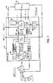
図2は、本発明の一実施形態に従った、LED駆動回路の回路図であり、図1のLED駆動インターフェース16の一部を形成する。電圧レギュレータ36は、電圧供給とは別個の電圧を酸素濃度計回路全体に対して提供する。その出力はライン38上の4.5ボルト信号として提供され、そのレベルは、抵抗R89およびR90のフィードバック抵抗ドライバによって設定される。ライン38上の電圧は、FETトランジスタQ11およびインダクタL6へ提供される。インダクタL6を通る電流は、スイッチ40によって、コンデンサC65およびC66のうちの一つに提供され、それらは、個々に、赤色およびIRLEDに対する電荷をストアする。ライン42上の赤/IR制御信号は、酸素濃度計のプロセッサの制御の下で、スイッチ位置を選択する。ライン44上の制御信号LED PWMゲートは、トランジスタスイッチQ11のスイッチングを制御する。(LED drive circuit)
FIG. 2 is a circuit diagram of an LED drive circuit according to an embodiment of the present invention, which forms part of the LED drive interface 16 of FIG. The
いったんコンデンサが充電されると、ライン44上の制御信号は、スイッチQ11をオフにし、電流はコンデンサC65またはC66のいずれかから、スイッチ40およびインダクタL6を通り、個々に、トランジスタQ5およびQ6を経由して、Redアノードライン46またはIRアノードライン48のいずれかに提供される。信号「red gate」はトランジスタQ5をオンにし、他方で、その反転の「/red gate」はトランジスタQ7をオフにする。これは、Redアノードライン46を通る電流を、背中合わせの(back to back)LED50に提供し、その電流は、IRアノードを通りトランジスタQ8へ、および、抵抗R10を通り接地へ戻る。トランジスタQ8は、信号「/IR gate(ゲート)」によってオンにされ、他方で、この信号の反転である「IR gate」はトランジスタQ6をオフにする。IRアノードが駆動される場合、その信号は反転され、「IR gate」および「red gate」信号およびそれらの反転は、それの状態が変化され、その結果、電流は、トランジスタQ6を通り、IRアノード48に提供され、Redアノード46およびトランジスタQ7を通り、抵抗R10および接地へと戻る。「LED電流センス」信号は、較正のために読まれるが、それは本発明とは関連しない。 Once the capacitor is charged, the control signal on
コンデンサC65またはC66からの電流は、インダクタL6を通り、LEDに提供される場合、および、その電流が、所望の時間においてスイッチをオフにされる場合、トランジスタQ11はオンにされ、遷移の間の残りの電流はコンデンサC64にダンプ(dump)され得る。これは、FETトランジスタのスイッチングが瞬時のものではないという事実を述べている。次に、コンデンサが再充電された場合、C64は、Q11およびインダクタL6を流れるその電流をコンデンサにダンプする。 If the current from capacitor C65 or C66 passes through inductor L6 and is provided to the LED, and if that current is switched off at the desired time, transistor Q11 is turned on and during the transition The remaining current can be dumped to capacitor C64. This describes the fact that FET transistor switching is not instantaneous. Then, when the capacitor is recharged, C64 dumps its current through Q11 and inductor L6 to the capacitor.
抵抗R38およびコンデンサC67は、インダクタL6にパラレルに接続され、信号スパイクに対して保護し、平滑な遷移を提供する。インダクタL6に接続されるのは、ライン54上のLEDサンプルホールド信号によって制御されるスイッチ52を有するサンプリング回路であり、信号をサンプルし、プロセッサによって読み出されるライン58上において、増幅器56を介して、それらを「LED電流」信号へ提供する。積分コンデンサC68は増幅器56のためのフィードバックを提供する。スイッチ60は、「クリアLEDサンプル」信号に応答して、スイッチを動作させ、サンプル間のコンデンサをショートさせる。 Resistor R38 and capacitor C67 are connected in parallel to inductor L6 to protect against signal spikes and provide a smooth transition. Connected to inductor L6 is a sampling circuit having a
演算増幅器56は4.5ボルトと接地との間において動作する。従って、0.2ボルトの接地の僅かに上の基準電圧は、ピン3上に基準電圧として提供される。 The
サンプルアンドホールド回路は、キャパシタC69とインダクタL6との間のノードT18における電圧を測定し、その電流をケッテインターフェースする。コンデンサC69は、C65およびC66の値の1/1000である。従って、比例した電流がC69に提供され、スイッチ52を通り、積分コンデンサC68に注入され、ライン58上の増幅器56の出力において測定され得る電圧を提供する。ライン58上のプロセッサによって測定された電圧は、フィードバックとして使用され、そのプロセッサは、コンデンサ65および66へ送られるエネルギーの量を選択的に変化させるために、トランジスタQ11に送られるパルスの幅を変化させ、その結果、LED50に放電される。プロセッサ内のPI(比例積分)ループは、次いで、Q11を制御するPWM信号を制御する。これによって、LED強度の正確な制御を可能にし、所望される場合、所望の制限を越えることなく、それを最大化させることを可能にする。 The sample and hold circuit measures the voltage at the node T18 between the capacitor C69 and the inductor L6, and kettes the current. Capacitor C69 is 1/1000 of the value of C65 and C66. Thus, a proportional current is provided to C69, injected through
図の左下は、「4.5v LED 無効」信号を示し、その信号は、所定の場合において、電圧レギュレータ36をオフにするためにマイクロプロセッサによって使用される。例えば、接続された新しいセンサにおいて、ショートを探す診断は、LEDラインに問題が存在する場合、その電圧レギュレータをオフにし得る。 The lower left of the figure shows a “4.5v LED disabled” signal, which is used by the microprocessor to turn off the
(LED電圧決定)
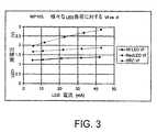
図3および図4は、本発明の開発を可能にした発明者らによって発見された属性を示す。図3は、LED電流に対するLED順電圧のグラフである。三つの異なるグラフは、IR LED、赤色LED、およびダイオードおよび抵抗を直列に有する機能試験器(SRC)の異なるタイプの負荷のための、三つの異なる傾きを有する三つの異なる線を生成する。見られ得るように、負荷のタイプを知らず、図3に示されるような曲線を蓄えていない場合は、電流のみを測定することは、LED順電圧が何であるのかを示さない。(LED voltage determination)
3 and 4 show the attributes discovered by the inventors that allowed the development of the present invention. FIG. 3 is a graph of LED forward voltage versus LED current. The three different graphs produce three different lines with three different slopes for different types of loads of a functional tester (SRC) having an IR LED, a red LED, and a diode and a resistor in series. As can be seen, if you do not know the type of load and have not stored the curve as shown in FIG. 3, measuring only the current does not indicate what the LED forward voltage is.
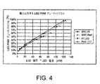
図4は、LED PWMデューティサイクルのプロットを示し、それは、LEDを駆動するためのパルス幅変調駆動信号である。これは、水平軸上の電力(LED電圧×LED電流)に対する垂直軸上にプロットされる。認識され得るように、プロットされた4つの異なるタイプのLEDまたはSRC装置のために、それらのプロットは、ほぼ同一の傾きとほぼ同一である。この認識から、発明者らは、PWMデューティサイクルおよびその電流を知っている場合、その電圧が決定され得ることを決定する。その電流は、図2におけるライン58から利用可能であり、そのLED電流信号はプロセッサに提供される。そのプロセッサ自体は、PWM信号を生成し、そのプロセッサは、LEDのタイプを知ることなしに、特定のLEDのLED電圧を計算する必要がある二つの情報を有する。デューティサイクルがLEDにおいて散逸される電力に対する定数によって比例することを示す図4における情報を使用することによって、順電圧は導かれ得る。 FIG. 4 shows a plot of the LED PWM duty cycle, which is a pulse width modulated drive signal for driving the LED. This is plotted on the vertical axis against power on the horizontal axis (LED voltage x LED current). As can be appreciated, for the four different types of LED or SRC devices plotted, the plots are approximately the same with approximately the same slope. From this recognition, we determine that if we know the PWM duty cycle and its current, its voltage can be determined. The current is available from
一実施形態において、PWM信号は、PI(比例積分)ループを使用して生成される。このループは以下で説明される等式の形を取る。 In one embodiment, the PWM signal is generated using a PI (proportional integral) loop. This loop takes the form of the equation described below.

あるいは、別の実施形態において、ルックアップテーブルは取り除かれ得、比較は、デューティサイクルおよび電流によってなされ得る。そのデューティサイクルは、電流×電圧×定数に等しいため、デューティサイクル/LED電流のレシオのための上下の範囲は確立され得、LEDにおけるショートまたはオープン接続などの状況を示す。あるいは、一連の範囲が使用され得、外部範囲はショートまたはオープン状況を示し、内部範囲は、一例として、LEDのための所望の動作範囲を示す。例えば、酸素濃度計は、弱いパルス信号を有する所定の患者のために、LEDをより強く、ほぼその最大電流にて、駆動する必要があり得る。 Alternatively, in another embodiment, the lookup table can be removed and the comparison can be made by duty cycle and current. Since its duty cycle is equal to current x voltage x constant, an upper and lower range for the duty cycle / LED current ratio can be established, indicating a situation such as a short or open connection in the LED. Alternatively, a series of ranges can be used, with the outer range indicating a short or open situation, and the inner range as an example indicates the desired operating range for the LED. For example, an oximeter may need to drive an LED stronger and at its maximum current for a given patient with a weak pulse signal.
当業者によって理解されるように、本発明はその本質的な特性から逸脱することなく他の特定の形式において具体化され得る。例えば、順電圧の決定は、プロセッサにおけるソフトウェアにおいてよりも、全体的にそのハードウェアにおいてなされ得る。従って、前述の記載は例示のためのみであり、請求の範囲において説明される本発明の範囲を限定するものではない。 As will be appreciated by those skilled in the art, the present invention may be embodied in other specific forms without departing from its essential characteristics. For example, the determination of the forward voltage can be made entirely in the hardware rather than in software in the processor. Accordingly, the foregoing description is by way of example only and is not intended to limit the scope of the invention described in the claims.
Claims (10)
Translated fromJapanese該LEDを流れる電流を測定する電流測定回路と、
該LEDへのパルス幅変調器(PWM)駆動信号を生成するコントローラと、
該コントローラおよび該電流測定回路に結合され、該LEDの順電圧が、該電流および該PWM信号の測定に使用される所定の範囲内にあるかどうかを決定するように構成されたプロセッサと
を備える、パルス酸素濃度計。At least one light emitting diode (LED) drive circuit;
A current measuring circuit for measuring a current flowing through the LED;
A controller that generates a pulse width modulator (PWM) drive signal to the LED;
A processor coupled to the controller and the current measurement circuit and configured to determine whether the forward voltage of the LED is within a predetermined range used to measure the current and the PWM signal. , Pulse oximeter.
該LEDを流れる電流を測定する電流測定回路と、
該LEDへのパルス幅変調器(PWM)駆動信号を生成するコントローラと、
該コントローラおよび該電流測定回路に結合され、レシオが許容電圧範囲内にあるかどうかを決定するために該PWM駆動信号を該電流の該測定と比較することによって、該LEDの順電圧が、該電流および該PWM信号の測定に使用される所定の電圧範囲内にあるかどうかを決定するように構成されたプロセッサとを備える、パルス酸素濃度計であって、
該順電圧が該電圧範囲外にある場合、該プロセッサは、エラー信号を提供するように構成され、
該プロセッサは、該電流の該測定と所望電流との間の相違を反映する電流誤差信号から該PWM信号を生成する比例積分(PI)ループを含む、パルス酸素濃度計。At least one light emitting diode (LED) drive circuit;
A current measuring circuit for measuring a current flowing through the LED;
A controller that generates a pulse width modulator (PWM) drive signal to the LED;
The forward voltage of the LED is coupled to the controller and the current measurement circuit and by comparing the PWM drive signal with the measurement of the current to determine if the ratio is within an acceptable voltage range. A pulse oximeter comprising: a processor configured to determine whether it is within a predetermined voltage range used to measure the current and the PWM signal;
If the forward voltage is outside the voltage range, the processor is configured to provide an error signal;
The pulse oximeter, wherein the processor includes a proportional integral (PI) loop that generates the PWM signal from a current error signal that reflects the difference between the measurement and the desired current of the current.
少なくとも1つの発光ダイオード(LED)駆動回路を使用して電流を供給する工程と、
該LEDを流れる電流を測定する工程と、
該LEDへのパルス幅変調器(PWM)駆動信号を生成する工程と、
該LEDの順電圧が、該電流および該PWM信号の測定に使用される所定の範囲内にあるかどうかを決定する工程と
を包含する、方法。A method of operating a pulse oximeter comprising:
Supplying current using at least one light emitting diode (LED) drive circuit;
Measuring the current flowing through the LED;
Generating a pulse width modulator (PWM) drive signal to the LED;
Determining whether the forward voltage of the LED is within a predetermined range used for measuring the current and the PWM signal.
少なくとも1つの発光ダイオード(LED)駆動回路を使用して電流を供給する工程と、
該LEDを流れる電流を測定する工程と、
該LEDへのパルス幅変調器(PWM)駆動信号を生成する工程と、
レシオが許容電圧範囲内にあるかどうかを決定するために該PWM駆動信号を該電流の該測定と比較することによって、該LEDの順電圧が、該電流および該PWM信号の測定に使用される所定の電圧範囲内にあるかどうかを決定する工程と、
該順電圧が該電圧範囲外にある場合、エラー信号を提供する工程と、
該電流の該測定と所望電流との間の相違を反映する電流誤差信号から該PWM信号を生成するために、比例積分(PI)ループを使用する工程と
を包含する、方法。A method of operating a pulse oximeter comprising:
Supplying current using at least one light emitting diode (LED) drive circuit;
Measuring the current flowing through the LED;
Generating a pulse width modulator (PWM) drive signal to the LED;
The forward voltage of the LED is used to measure the current and the PWM signal by comparing the PWM drive signal with the measurement of the current to determine if the ratio is within an acceptable voltage range. Determining whether it is within a predetermined voltage range;
Providing an error signal if the forward voltage is outside the voltage range;
Using a proportional-integral (PI) loop to generate the PWM signal from a current error signal reflecting the difference between the measurement of the current and a desired current.
Applications Claiming Priority (2)
| Application Number | Priority Date | Filing Date | Title |
|---|---|---|---|
| US10/788,243US7120480B2 (en) | 2004-02-25 | 2004-02-25 | LED forward voltage estimation in pulse oximeter |
| PCT/US2005/006205WO2005082455A1 (en) | 2004-02-25 | 2005-02-25 | Led forward voltage estimation in pulse oximeter |
Publications (1)
| Publication Number | Publication Date |
|---|---|
| JP2007523730Atrue JP2007523730A (en) | 2007-08-23 |
Family
ID=34861966
Family Applications (1)
| Application Number | Title | Priority Date | Filing Date |
|---|---|---|---|
| JP2007501029APendingJP2007523730A (en) | 2004-02-25 | 2005-02-25 | LED forward voltage estimation in pulse oximeter |
Country Status (9)
| Country | Link |
|---|---|
| US (1) | US7120480B2 (en) |
| EP (1) | EP1722854A1 (en) |
| JP (1) | JP2007523730A (en) |
| KR (1) | KR20060134102A (en) |
| CN (1) | CN1929890A (en) |
| AU (1) | AU2005216973A1 (en) |
| CA (1) | CA2556716A1 (en) |
| MX (1) | MXPA06009752A (en) |
| WO (1) | WO2005082455A1 (en) |
Families Citing this family (22)
| Publication number | Priority date | Publication date | Assignee | Title |
|---|---|---|---|---|
| US7647083B2 (en) | 2005-03-01 | 2010-01-12 | Masimo Laboratories, Inc. | Multiple wavelength sensor equalization |
| US7999484B2 (en) | 2005-12-20 | 2011-08-16 | Koninklijke Philips Electronics N.V. | Method and apparatus for controlling current supplied to electronic devices |
| JP5043111B2 (en)* | 2006-08-17 | 2012-10-10 | コーニンクレッカ フィリップス エレクトロニクス エヌ ヴィ | Method and apparatus for reducing thermal stress in light emitting devices |
| US8265723B1 (en) | 2006-10-12 | 2012-09-11 | Cercacor Laboratories, Inc. | Oximeter probe off indicator defining probe off space |
| US20080221418A1 (en)* | 2007-03-09 | 2008-09-11 | Masimo Corporation | Noninvasive multi-parameter patient monitor |
| US8265724B2 (en) | 2007-03-09 | 2012-09-11 | Nellcor Puritan Bennett Llc | Cancellation of light shunting |
| EP2139383B1 (en) | 2007-03-27 | 2013-02-13 | Masimo Laboratories, Inc. | Multiple wavelength optical sensor |
| US20080262326A1 (en)* | 2007-04-19 | 2008-10-23 | Starr Life Sciences Corp. | Signal Processing Method and Apparatus for Processing a Physiologic Signal such as a Photoplethysmography Signal |
| US8374665B2 (en) | 2007-04-21 | 2013-02-12 | Cercacor Laboratories, Inc. | Tissue profile wellness monitor |
| TWI367050B (en)* | 2007-12-12 | 2012-06-21 | Au Optronics Corp | Color control method for led lighting system |
| US8366613B2 (en) | 2007-12-26 | 2013-02-05 | Covidien Lp | LED drive circuit for pulse oximetry and method for using same |
| EP2262414A1 (en)* | 2008-03-31 | 2010-12-22 | Nellcor Puritan Bennett LLC | Medical monitoring patch device and methods |
| US9404961B2 (en)* | 2008-12-09 | 2016-08-02 | Covidien Lp | System and method of determining light source aging |
| US9066660B2 (en) | 2009-09-29 | 2015-06-30 | Nellcor Puritan Bennett Ireland | Systems and methods for high-pass filtering a photoplethysmograph signal |
| US9839381B1 (en) | 2009-11-24 | 2017-12-12 | Cercacor Laboratories, Inc. | Physiological measurement system with automatic wavelength adjustment |
| WO2011069122A1 (en) | 2009-12-04 | 2011-06-09 | Masimo Corporation | Calibration for multi-stage physiological monitors |
| US20120253151A1 (en)* | 2011-03-30 | 2012-10-04 | Nellcor Puritan Bennett Llc | Multiple Wavelength Pulse Oximetry With Sensor Redundancy |
| US20150196239A1 (en)* | 2014-01-10 | 2015-07-16 | Covidien Lp | Method and apparatus for driving an emitter in a medical sensor |
| US20180353111A1 (en)* | 2017-06-09 | 2018-12-13 | Covidien Lp | Systems and methods for driving optical sensors |
| US10852230B1 (en) | 2020-04-24 | 2020-12-01 | Covidien Lp | Sensor characterization through forward voltage measurements |
| US10849538B1 (en) | 2020-04-24 | 2020-12-01 | Covidien Lp | Sensor verification through forward voltage measurements |
| JP7574033B2 (en)* | 2020-09-30 | 2024-10-28 | 日本光電工業株式会社 | Biological parameter calculation device, computer program, and non-transitory computer-readable medium |
Citations (3)
| Publication number | Priority date | Publication date | Assignee | Title |
|---|---|---|---|---|
| JPH04256733A (en)* | 1990-09-28 | 1992-09-11 | Hewlett Packard Co <Hp> | Measuring apparatus and method for blood parameter |
| JP2002525151A (en)* | 1998-09-29 | 2002-08-13 | マリンクロッド・インコーポレイテッド | Oximeter sensor with encoded temperature characteristics |
| WO2003068060A1 (en)* | 2002-02-15 | 2003-08-21 | Datex-Ohmeda, Inc. | Compensation of human variability in pulse oximetry |
Family Cites Families (15)
| Publication number | Priority date | Publication date | Assignee | Title |
|---|---|---|---|---|
| US4934372A (en)* | 1985-04-01 | 1990-06-19 | Nellcor Incorporated | Method and apparatus for detecting optical pulses |
| US4911167A (en)* | 1985-06-07 | 1990-03-27 | Nellcor Incorporated | Method and apparatus for detecting optical pulses |
| US4802486A (en) | 1985-04-01 | 1989-02-07 | Nellcor Incorporated | Method and apparatus for detecting optical pulses |
| US4928692A (en)* | 1985-04-01 | 1990-05-29 | Goodman David E | Method and apparatus for detecting optical pulses |
| US4802488A (en)* | 1986-11-06 | 1989-02-07 | Sri International | Blood pressure monitoring method and apparatus |
| US5351685A (en)* | 1991-08-05 | 1994-10-04 | Nellcor Incorporated | Condensed oximeter system with noise reduction software |
| JP3165983B2 (en)* | 1992-06-15 | 2001-05-14 | 日本光電工業株式会社 | Light emitting element driving device for pulse oximeter |
| US5368224A (en)* | 1992-10-23 | 1994-11-29 | Nellcor Incorporated | Method for reducing ambient noise effects in electronic monitoring instruments |
| US5368026A (en)* | 1993-03-26 | 1994-11-29 | Nellcor Incorporated | Oximeter with motion detection for alarm modification |
| US5859658A (en)* | 1995-10-19 | 1999-01-12 | Xerox Corporation | LED printbar aging compensation using I-V slope characteristics |
| US5746697A (en)* | 1996-02-09 | 1998-05-05 | Nellcor Puritan Bennett Incorporated | Medical diagnostic apparatus with sleep mode |
| US5821921A (en)* | 1996-08-09 | 1998-10-13 | Osborn; John J. | Cursor controller having cross-translating platforms with a cantilevered handle |
| US5921921A (en) | 1996-12-18 | 1999-07-13 | Nellcor Puritan-Bennett | Pulse oximeter with sigma-delta converter |
| US6226539B1 (en)* | 1999-05-26 | 2001-05-01 | Mallinckrodt, Inc. | Pulse oximeter having a low power led drive |
| US6560470B1 (en)* | 2000-11-15 | 2003-05-06 | Datex-Ohmeda, Inc. | Electrical lockout photoplethysmographic measurement system |
- 2004
- 2004-02-25USUS10/788,243patent/US7120480B2/ennot_activeExpired - Lifetime
- 2005
- 2005-02-25KRKR1020067018547Apatent/KR20060134102A/ennot_activeWithdrawn
- 2005-02-25AUAU2005216973Apatent/AU2005216973A1/ennot_activeAbandoned
- 2005-02-25MXMXPA06009752Apatent/MXPA06009752A/ennot_activeApplication Discontinuation
- 2005-02-25CACA002556716Apatent/CA2556716A1/ennot_activeAbandoned
- 2005-02-25JPJP2007501029Apatent/JP2007523730A/enactivePending
- 2005-02-25WOPCT/US2005/006205patent/WO2005082455A1/enactiveApplication Filing
- 2005-02-25EPEP05723884Apatent/EP1722854A1/ennot_activeWithdrawn
- 2005-02-25CNCNA2005800058571Apatent/CN1929890A/enactivePending
Patent Citations (3)
| Publication number | Priority date | Publication date | Assignee | Title |
|---|---|---|---|---|
| JPH04256733A (en)* | 1990-09-28 | 1992-09-11 | Hewlett Packard Co <Hp> | Measuring apparatus and method for blood parameter |
| JP2002525151A (en)* | 1998-09-29 | 2002-08-13 | マリンクロッド・インコーポレイテッド | Oximeter sensor with encoded temperature characteristics |
| WO2003068060A1 (en)* | 2002-02-15 | 2003-08-21 | Datex-Ohmeda, Inc. | Compensation of human variability in pulse oximetry |
Also Published As
| Publication number | Publication date |
|---|---|
| CN1929890A (en) | 2007-03-14 |
| MXPA06009752A (en) | 2007-03-15 |
| CA2556716A1 (en) | 2005-09-09 |
| EP1722854A1 (en) | 2006-11-22 |
| KR20060134102A (en) | 2006-12-27 |
| WO2005082455A1 (en) | 2005-09-09 |
| US7120480B2 (en) | 2006-10-10 |
| US20050187450A1 (en) | 2005-08-25 |
| AU2005216973A1 (en) | 2005-09-09 |
Similar Documents
| Publication | Publication Date | Title |
|---|---|---|
| JP2007523730A (en) | LED forward voltage estimation in pulse oximeter | |
| EP1722673B1 (en) | Switch-mode oximeter led drive with a single inductor | |
| US6668183B2 (en) | Diode detection circuit | |
| US11246515B2 (en) | LED control utilizing ambient light or signal quality | |
| US6863652B2 (en) | Power conserving adaptive control system for generating signal in portable medical devices | |
| US7373192B2 (en) | Oximeter red and IR zero calibration control | |
| US12082945B2 (en) | Systems and methods for low power pulse oximetry | |
| US20070123760A1 (en) | Signal transmitter and control circuit for a physiological variable | |
| US11849923B2 (en) | Wearable blood gas monitor | |
| JP4962234B2 (en) | Pulse oximeter | |
| US12064242B2 (en) | Systems and methods for measuring oxygen in a patient's bloodstream | |
| WO2022050368A1 (en) | Pulse wave signal acquisition device | |
| US20250072876A1 (en) | Miniaturized bimodal oxygen monitoring wearable device | |
| WO2025106943A1 (en) | Miniaturized bimodal oxygen monitoring wearable device | |
| KR20070020427A (en) | Device for detecting heart rate and reducing power consumption of the sensor | |
| JP2007236645A (en) | Light emitting device actuation circuit of optical bioinformation measuring instrument |
Legal Events
| Date | Code | Title | Description |
|---|---|---|---|
| A621 | Written request for application examination | Free format text:JAPANESE INTERMEDIATE CODE: A621 Effective date:20080219 | |
| RD02 | Notification of acceptance of power of attorney | Free format text:JAPANESE INTERMEDIATE CODE: A7422 Effective date:20080717 | |
| RD04 | Notification of resignation of power of attorney | Free format text:JAPANESE INTERMEDIATE CODE: A7424 Effective date:20080717 | |
| A131 | Notification of reasons for refusal | Free format text:JAPANESE INTERMEDIATE CODE: A131 Effective date:20101015 | |
| A02 | Decision of refusal | Free format text:JAPANESE INTERMEDIATE CODE: A02 Effective date:20110329 |