JP2007523668A - Manual or pump fluid dispenser - Google Patents
Manual or pump fluid dispenserDownload PDFInfo
- Publication number
- JP2007523668A JP2007523668AJP2006515593AJP2006515593AJP2007523668AJP 2007523668 AJP2007523668 AJP 2007523668AJP 2006515593 AJP2006515593 AJP 2006515593AJP 2006515593 AJP2006515593 AJP 2006515593AJP 2007523668 AJP2007523668 AJP 2007523668A
- Authority
- JP
- Japan
- Prior art keywords
- container
- cap
- liquid
- fluid
- outlet
- Prior art date
- Legal status (The legal status is an assumption and is not a legal conclusion. Google has not performed a legal analysis and makes no representation as to the accuracy of the status listed.)
- Granted
Links
- 239000012530fluidSubstances0.000titleclaimsabstractdescription126
- 239000007788liquidSubstances0.000claimsdescription202
- 230000007246mechanismEffects0.000claimsdescription24
- 238000000034methodMethods0.000claimsdescription10
- 238000007789sealingMethods0.000claimsdescription8
- 230000005484gravityEffects0.000claimsdescription7
- 238000007599dischargingMethods0.000claimsdescription5
- 230000000149penetrating effectEffects0.000claimsdescription4
- 230000004888barrier functionEffects0.000claimsdescription2
- 230000005670electromagnetic radiationEffects0.000claimsdescription2
- 230000002265preventionEffects0.000claims1
- 239000000344soapSubstances0.000description12
- XLYOFNOQVPJJNP-UHFFFAOYSA-NwaterSubstancesOXLYOFNOQVPJJNP-UHFFFAOYSA-N0.000description8
- 238000007906compressionMethods0.000description4
- 230000006835compressionEffects0.000description4
- 238000004880explosionMethods0.000description4
- 239000002184metalSubstances0.000description4
- 230000004048modificationEffects0.000description4
- 238000012986modificationMethods0.000description4
- 239000000758substrateSubstances0.000description4
- LFQSCWFLJHTTHZ-UHFFFAOYSA-NEthanolChemical compoundCCOLFQSCWFLJHTTHZ-UHFFFAOYSA-N0.000description3
- RNFJDJUURJAICM-UHFFFAOYSA-N2,2,4,4,6,6-hexaphenoxy-1,3,5-triaza-2$l^{5},4$l^{5},6$l^{5}-triphosphacyclohexa-1,3,5-trieneChemical compoundN=1P(OC=2C=CC=CC=2)(OC=2C=CC=CC=2)=NP(OC=2C=CC=CC=2)(OC=2C=CC=CC=2)=NP=1(OC=1C=CC=CC=1)OC1=CC=CC=C1RNFJDJUURJAICM-UHFFFAOYSA-N0.000description2
- 239000003063flame retardantSubstances0.000description2
- 239000000463materialSubstances0.000description2
- 238000005086pumpingMethods0.000description2
- 230000005855radiationEffects0.000description2
- 230000009471actionEffects0.000description1
- 230000004913activationEffects0.000description1
- 230000001476alcoholic effectEffects0.000description1
- 238000000071blow mouldingMethods0.000description1
- 238000004140cleaningMethods0.000description1
- 230000009849deactivationEffects0.000description1
- 239000000645desinfectantSubstances0.000description1
- 239000003599detergentSubstances0.000description1
- 238000009826distributionMethods0.000description1
- 238000005265energy consumptionMethods0.000description1
- 238000007667floatingMethods0.000description1
- 238000009472formulationMethods0.000description1
- 238000002347injectionMethods0.000description1
- 239000007924injectionSubstances0.000description1
- 238000003780insertionMethods0.000description1
- 230000037431insertionEffects0.000description1
- 239000000203mixtureSubstances0.000description1
- 230000035515penetrationEffects0.000description1
- 238000003825pressingMethods0.000description1
- 238000003860storageMethods0.000description1
Images


Classifications
- B—PERFORMING OPERATIONS; TRANSPORTING
- B05—SPRAYING OR ATOMISING IN GENERAL; APPLYING FLUENT MATERIALS TO SURFACES, IN GENERAL
- B05B—SPRAYING APPARATUS; ATOMISING APPARATUS; NOZZLES
- B05B9/00—Spraying apparatus for discharge of liquids or other fluent material, without essentially mixing with gas or vapour
- B05B9/03—Spraying apparatus for discharge of liquids or other fluent material, without essentially mixing with gas or vapour characterised by means for supplying liquid or other fluent material
- B05B9/04—Spraying apparatus for discharge of liquids or other fluent material, without essentially mixing with gas or vapour characterised by means for supplying liquid or other fluent material with pressurised or compressible container; with pump
- B05B9/08—Apparatus to be carried on or by a person, e.g. of knapsack type
- B05B9/085—Apparatus to be carried on or by a person, e.g. of knapsack type with a liquid pump
- B05B9/0855—Apparatus to be carried on or by a person, e.g. of knapsack type with a liquid pump the pump being motor-driven
- B05B9/0861—Apparatus to be carried on or by a person, e.g. of knapsack type with a liquid pump the pump being motor-driven the motor being electric
- A—HUMAN NECESSITIES
- A47—FURNITURE; DOMESTIC ARTICLES OR APPLIANCES; COFFEE MILLS; SPICE MILLS; SUCTION CLEANERS IN GENERAL
- A47K—SANITARY EQUIPMENT NOT OTHERWISE PROVIDED FOR; TOILET ACCESSORIES
- A47K5/00—Holders or dispensers for soap, toothpaste, or the like
- A47K5/06—Dispensers for soap
- A47K5/12—Dispensers for soap for liquid or pasty soap
- A47K5/1202—Dispensers for soap for liquid or pasty soap dispensing dosed volume
- A—HUMAN NECESSITIES
- A47—FURNITURE; DOMESTIC ARTICLES OR APPLIANCES; COFFEE MILLS; SPICE MILLS; SUCTION CLEANERS IN GENERAL
- A47K—SANITARY EQUIPMENT NOT OTHERWISE PROVIDED FOR; TOILET ACCESSORIES
- A47K5/00—Holders or dispensers for soap, toothpaste, or the like
- A47K5/06—Dispensers for soap
- A47K5/12—Dispensers for soap for liquid or pasty soap
- A47K5/1217—Electrical control means for the dispensing mechanism
- A—HUMAN NECESSITIES
- A47—FURNITURE; DOMESTIC ARTICLES OR APPLIANCES; COFFEE MILLS; SPICE MILLS; SUCTION CLEANERS IN GENERAL
- A47K—SANITARY EQUIPMENT NOT OTHERWISE PROVIDED FOR; TOILET ACCESSORIES
- A47K5/00—Holders or dispensers for soap, toothpaste, or the like
- A47K5/06—Dispensers for soap
- A47K5/12—Dispensers for soap for liquid or pasty soap
- A47K5/122—Dispensers for soap for liquid or pasty soap using squeeze bottles or the like
- B—PERFORMING OPERATIONS; TRANSPORTING
- B05—SPRAYING OR ATOMISING IN GENERAL; APPLYING FLUENT MATERIALS TO SURFACES, IN GENERAL
- B05B—SPRAYING APPARATUS; ATOMISING APPARATUS; NOZZLES
- B05B11/00—Single-unit hand-held apparatus in which flow of contents is produced by the muscular force of the operator at the moment of use
- B05B11/0005—Components or details
- B05B11/0037—Containers
- B05B11/0039—Containers associated with means for compensating the pressure difference between the ambient pressure and the pressure inside the container, e.g. pressure relief means
- B05B11/0044—Containers associated with means for compensating the pressure difference between the ambient pressure and the pressure inside the container, e.g. pressure relief means compensating underpressure by ingress of atmospheric air into the container, i.e. with venting means
- B—PERFORMING OPERATIONS; TRANSPORTING
- B05—SPRAYING OR ATOMISING IN GENERAL; APPLYING FLUENT MATERIALS TO SURFACES, IN GENERAL
- B05B—SPRAYING APPARATUS; ATOMISING APPARATUS; NOZZLES
- B05B11/00—Single-unit hand-held apparatus in which flow of contents is produced by the muscular force of the operator at the moment of use
- B05B11/0005—Components or details
- B05B11/0059—Components or details allowing operation in any orientation, e.g. for discharge in inverted position
Landscapes
- Health & Medical Sciences (AREA)
- Public Health (AREA)
- Containers And Packaging Bodies Having A Special Means To Remove Contents (AREA)
- Closures For Containers (AREA)
Abstract
Translated fromJapaneseDescription
Translated fromJapanese本発明は流体ディスペンサーに関し、より具体的には自動及び/又は手動ポンプ式の流体ディスペンサーに関する。The present invention relates to fluid dispensers, and more particularly to automatic and / or manually pumped fluid dispensers.
公知のソープディスペンサーの大部分は、特にモーター式ポンプで自動的に流体を払出すタイプのものは、安価で単純にかつ/又はエネルギー効率良く流体を払出すものではないという点で不都合である。更に不都合なことに、モーター式ポンプを備えた公知のディスペンサーでは、例えばモーター式ポンプが作動しない場合に、モーター式ポンプを使用せずに液体を手動で払出すことができない。ポンプが作動しない理由としては、例えば、ポンプ機構の故障、停電やポンプ作動用のバッテリーの消耗等による動力不足が考えられる。Most of the known soap dispensers are disadvantageous in that they are not cheap, simply and / or energy efficient, especially those that automatically dispense fluid with a motorized pump. Further disadvantageously, known dispensers with motor-type pumps cannot dispense liquids manually without the use of motor-type pumps, for example when the motor-type pump does not operate. Possible reasons for the pump not to operate include power shortage due to a pump mechanism failure, power failure, exhaustion of a battery for pump operation, and the like.
従来公知のディスペンサーの上記欠点を少なくとも部分的に解決するため、本発明は、ある態様において、逆さ状態の容器の開口部の周りに設置されたチャンバーであって、その内部に配置した回転翼が回転してチャンバーから流体を払出すようなチャンバーを提供する。このようなチャンバーは真空除去用チャンバーであることがより好ましい。In order to at least partially solve the above-described drawbacks of known dispensers, in one aspect, the present invention provides a chamber installed around an opening of an inverted container, and a rotor disposed inside the chamber. A chamber is provided that rotates to dispense fluid from the chamber. More preferably, such a chamber is a vacuum removal chamber.
本発明の一つの目的は、モーター式ポンプで流体を払出す簡易型流体ディスペンサーの提供である。One object of the present invention is to provide a simplified fluid dispenser that dispenses fluid with a motor-type pump.
本発明の別の目的は、流体を払出すためのモーター式ポンプを備えていて、バッテリーでの使用に特に適した安価な流体ディスペンサーの提供である。Another object of the present invention is to provide an inexpensive fluid dispenser that is equipped with a motorized pump for dispensing fluid and that is particularly suitable for use with batteries.
別の目的は、モーター又は手動でポンプを作動させることによる払出しが可能な流体ディスペンサーの提供である。Another object is to provide a fluid dispenser that can be dispensed by motor or manual pump actuation.
別の目的は、不使用時に液体が垂れない液体ディスペンサーの提供である。Another object is to provide a liquid dispenser that does not drip when not in use.
従って、本発明はある態様において、以下:Accordingly, the present invention in certain embodiments provides:
一方の側がくびれていて排出口がある以外は閉鎖された弾性容器、An elastic container that is closed except for one side that is constricted and has an outlet,
端壁、及び、端壁から上へ伸びる側壁を有するキャップ、A cap having an end wall and a side wall extending upward from the end wall;
側壁を貫通するキャップ出口、A cap outlet penetrating the side wall,
くびれ部とキャップの側壁の間の、くびれ部の外側でかつ側壁の内側にある、容器出口及びキャップ出口の両方につながる通路、A passage between the constriction and the side wall of the cap, outside the constriction and inside the side wall, leading to both the container outlet and the cap outlet;
キャップの端壁の上に配置されていて、軸の周りを回転できるように軸受けに受けられ、容器出口の少なくとも少し下に配置された回転翼:
を含み、A rotor blade disposed on the end wall of the cap, received by a bearing so as to be able to rotate about an axis, and disposed at least slightly below the container outlet:
Including
上記キャップはくびれ部がキャップの中に入る形でくびれ部に受けられ、The cap is received by the constricted part in a form in which the constricted part enters the cap,
キャップのくびれ部周囲の部分はくびれ部とかみ合わされることによって流体浸透防止用密閉部を形成し、The portion around the constricted portion of the cap is engaged with the constricted portion to form a fluid permeation preventing sealing portion,
容器が逆さになっていてくびれ部が容器の下に位置した状態にある場合に、容器出口はキャップ出口より下にあり、When the container is upside down and the constriction is located under the container, the container outlet is below the cap outlet,
キャップの側壁は軸の周りに配置され、The side wall of the cap is arranged around the axis,
容器出口はキャップの側壁の内側に同軸方向に配置され、The container outlet is arranged coaxially inside the side wall of the cap,
回転翼は、回転すると、容器出口から流出した回転翼の上にある流体を受け、かつ、液体を通路の中に放射状に外側へ流動させ、回転翼の回転によって流体を通路に流入させて通路の中の流体面をキャップ出口よりも高く上昇させ、流体をキャップ出口から流出させることができ、When the rotor blades rotate, the rotor blades receive the fluid on the rotor blades that have flowed out from the container outlet, cause the liquid to flow radially outward into the passage, and cause the fluid to flow into the passages by the rotation of the rotor blades. The fluid level inside can be raised higher than the cap outlet, allowing fluid to flow out of the cap outlet,
回転翼は、回転していない場合に、キャップ出口から容器出口への空気の流動を妨げないことを特徴とする液体ディスペンサーを提供する。The rotor blades provide a liquid dispenser that does not interfere with the flow of air from the cap outlet to the container outlet when not rotating.
別の態様において、本発明は、以下:In another embodiment, the present invention provides the following:
一方の下端がくびれていて排出口がある以外は閉鎖された弾性容器、An elastic container that is closed except that one lower end is constricted and there is a discharge port,
回転自在な状態でチャンバーの中に配置され、回転時には硬い通路を通して容器から液体を引っ張り、チャンバー中の液面を空気流入口よりも上昇させるような回転翼:
を含み、A rotating blade that is placed in the chamber in a freely rotating state, pulls liquid from the container through a hard passage during rotation, and raises the liquid level in the chamber above the air inlet:
Including
容器出口は、チャンバー外郭であるチャンバー形成要素と密閉状態でつながっていて、The container outlet is connected in a sealed state to a chamber forming element that is a chamber outline,
チャンバーは空気流入口及び液体流入口を有し、The chamber has an air inlet and a liquid inlet;
液体流入口はチャンバーの空気流入口よりも下にあり、The liquid inlet is below the chamber air inlet,
空気流入口は大気圧の空気とつながっていてチャンバー内部の圧力を大気圧とし、The air inlet is connected to atmospheric pressure air, and the pressure inside the chamber is set to atmospheric pressure.
液体流入口は液体通路を介して容器中の液体とつながっていて、The liquid inlet is connected to the liquid in the container through the liquid passage,
液体流入口は容器中の液面よりも下にあって、容器内部の圧力が大気圧である場合に、重力によって容器から流出した液体により液体通路が満たされ、かつ、液体通路を介して液体流入口よりも高くて空気流入口よりも下の位置までチャンバーが満たされることによって、容器から液体が払出される際に容器内部の圧力が大気圧よりも低くなって真空度が増大し、チャンバー中の液面が液体流入口よりも下まで下がって液体流入口とチャンバー中の空気とがつながることにより、チャンバー中の空気が重力で液体通路を通って容器へと上向きに流れて貯蔵器内部の真空度を減少させる
ことを特徴とする液体ディスペンサーを提供する。When the liquid inlet is below the liquid level in the container and the pressure inside the container is atmospheric pressure, the liquid passage is filled with the liquid flowing out of the container due to gravity, and the liquid is passed through the liquid passage. By filling the chamber to a position higher than the inlet and below the air inlet, when the liquid is discharged from the container, the pressure inside the container becomes lower than the atmospheric pressure, and the degree of vacuum increases. As the liquid level in the chamber drops below the liquid inlet and the liquid inlet and the air in the chamber are connected, the air in the chamber flows upward to the container through the liquid passage due to gravity. The liquid dispenser is characterized by reducing the degree of vacuum.
別の態様において、本発明は、以下:In another embodiment, the present invention provides the following:
電動モーター、Electric motor,
バッテリー、battery,
電子制御回路、及び、Electronic control circuit, and
電磁放射感知及び/又は受信装置:
を含み、Electromagnetic radiation sensing and / or receiving device:
Including
モーターが作動して流体ディスペンサーから流体が払出され、The motor is activated and fluid is dispensed from the fluid dispenser,
制御装置はバッテリーからモーターへの動力供給を制御し、かつ、感知及び/又は受信装置を制御し、The control device controls the power supply from the battery to the motor and controls the sensing and / or receiving device,
モーター、バッテリー、制御盤並びに感知及び/又は受信装置は、同一のユニットと交換するために取り外し可能な一体型電動組み立てユニットを構成する
ことを特徴とする自動流体ディスペンサーを提供する。The motor, battery, control board and sensing and / or receiving device provide an automatic fluid dispenser characterized in that it constitutes an integrated electric assembly unit that can be removed for replacement with the same unit.
別の態様において、本発明は、土台、土台から上へ伸びる側壁、及び、土台よりも高い位置に排出口を有する容器から流体を払出す方法であって、In another aspect, the present invention is a method for dispensing fluid from a base, a side wall extending upward from the base, and a container having an outlet at a position higher than the base,
排出口より低い位置にある容器に流体を供給すること、Supplying fluid to a container located below the outlet;
軸の周りを回転して、回転翼に接触している流体を放出できる回転翼を容器の中に設置して、容器中で流体を流動させて容器中の流体面を排出口の高さまで上昇させ、排出口より上にある流体を排出口から容器の外へ流出させること:を含む
ことを特徴とする方法を提供する。A rotating blade that can rotate around the shaft and discharge the fluid in contact with the rotating blade is installed in the container, and the fluid flows in the container to raise the fluid surface in the container to the height of the discharge port. And allowing the fluid above the outlet to flow out of the container from the outlet.
図面の簡単な説明
本発明の上記以外の態様及び利点は、以下の記載及び付随の図面から明らかに分かるであろう。BRIEF DESCRIPTION OF THE DRAWINGS Other aspects and advantages of the present invention will become apparent from the following description and accompanying drawings.
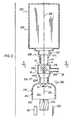
図1は、本発明の第一の実施形態によるソープディスペンサーの透視図である。FIG. 1 is a perspective view of a soap dispenser according to a first embodiment of the present invention.
図2は、図1のソープディスペンサーを分解した部分断面概略図である。FIG. 2 is a partial cross-sectional schematic view of the soap dispenser of FIG. 1 disassembled.
図3は、図3中の断面3−3’におけるボトルの端面図である。FIG. 3 is an end view of the bottle at a section 3-3 ′ in FIG. 3.
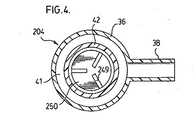
図4は、図5中の断面4−4’におけるキャップの断面図である。4 is a cross-sectional view of the cap taken along a section 4-4 'in FIG.
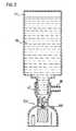
図5は、図1のソープディスペンサーを閉じた状態の部分断面図である。FIG. 5 is a partial cross-sectional view of the soap dispenser of FIG. 1 in a closed state.
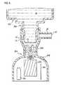
図6は、ソープディスペンサーを開いた状態の図3と同様の図である。FIG. 6 is a view similar to FIG. 3 with the soap dispenser open.
図7は、ディスペンサーの全体を示す図6と同様の図である。FIG. 7 is a view similar to FIG. 6 showing the entire dispenser.
図8は、第一の実施形態と同様のディスペンサーで使用するために改変したボトルの側面断面図である。FIG. 8 is a side cross-sectional view of a bottle modified for use with a dispenser similar to the first embodiment.
図9は、第一の実施形態と同様のボトルを圧迫する手動レバー機構の概略図である。FIG. 9 is a schematic view of a manual lever mechanism that compresses the same bottle as in the first embodiment.
図10は、本発明の第二の実施形態によるディスペンサーの図6と同様の断面図である。FIG. 10 is a cross-sectional view similar to FIG. 6 of the dispenser according to the second embodiment of the present invention.
図11は、本発明の第三の実施形態によるディスペンサーの後部の縦方向の断面図である。FIG. 11 is a longitudinal sectional view of the rear part of the dispenser according to the third embodiment of the present invention.
図12は、図11中の断面12−12’における断面図である。12 is a cross-sectional view taken along a cross section 12-12 'in FIG.
図13は、本発明の第三の実施形態によるディスペンサーの図6と同様の断面図である。FIG. 13 is a cross-sectional view similar to FIG. 6 of a dispenser according to the third embodiment of the present invention.
図14は、図13中の断面14−14’における断面図である。FIG. 14 is a sectional view taken along a section 14-14 'in FIG.
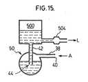
図15〜21は、流体ディスペンサーとして使用する際の流体貯蔵器、圧力除去機構及びポンプの配置をそれぞれ示す。FIGS. 15-21 show the arrangement of the fluid reservoir, pressure relief mechanism and pump, respectively, when used as a fluid dispenser.
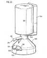
図22は、本発明の第四の実施形態によるディスペンサーの概略図である。FIG. 22 is a schematic view of a dispenser according to the fourth embodiment of the present invention.
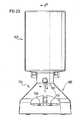
図23は、図22のディスペンサーの正面図である。FIG. 23 is a front view of the dispenser of FIG.
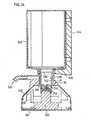
図24は、断面A−A’における図23のディスペンサーの断面図である。24 is a cross-sectional view of the dispenser of FIG. 23 taken along section A-A ′.
図25は、図22のディスペンサーを分解した概略図である。FIG. 25 is an exploded schematic view of the dispenser of FIG.
図26は、図25中に示すディスペンサーを分解した構成要素の正面概略図である。FIG. 26 is a schematic front view of components disassembled from the dispenser shown in FIG. 25.
図27は、図25中に示す容器の代わりに使用する難燃性容器の側面断面図である。27 is a side cross-sectional view of a flame retardant container used in place of the container shown in FIG.
本発明による流体ディスペンサーの第一の実施形態を示す図1〜7について説明する。1 to 7 showing a first embodiment of a fluid dispenser according to the present invention will be described.
図1は、ボトル202及びキャップ204を含むディスペンサー200を示す。FIG. 1 shows a
ボトル202は、図3中に示すように断面が長方形である胴部206、及び、縦軸210の周囲の断面が概して円形であるくびれ部208を有する。くびれ部208は、中心に雄ねじ214を有するくびれ部分212を含む。中心部分212の先は液体管42になっており、その端は容器出口44になっている。As shown in FIG. 3, the
キャップ204は土台34を有し、この土台から側壁36が上へ伸び、その上部に開口部37がある。側壁36の上部230は雌ねじ216を有していて、これをボトル202のくびれ部分212に取り付けることにより流体を密閉できる。空気管38は、側壁36から放射状に伸びている。側壁36の円筒状の最下部228は土台34から上へ伸びていて、その先は上向きに開いた漏斗状(frustoconical)部分229になっており、この漏斗状部分の上端の先は円筒状になっている。空気管38は、キャップ最上部のねじ部216より下から放射状に伸びている。The
キャップは支持部238を含み、この支持部の側壁240は土台34の周りから下へ外側に伸びていてその先は平坦な土台面242になっており、平坦な机や作業台の表面等への取り付け、及び、図示のようなディスペンサーの垂直方向での支持に適している。支持部238の内部はチャンバー244になっている。The cap includes a
回転翼250は、キャップ204内部の土台34の上の、円筒状の側壁36の内部に配置される。回転翼250は軸210の周りを回転するように配置される。この点について、好ましい実施形態においては、土台34を貫通する軸210と同軸方向に軸穴252があいている。シャフト254がこの穴252を通っていて、このシャフトの上端は回転翼250と、下端はチャンバー244内部に固定されたモーター256と連結している。穴252の中のシャフト254周辺に密閉リングが配置されていて、穴252から液体が外へ通過するのを妨げる流体浸透防止用密閉部を形成している。モーター256が作動すると、回転翼が軸210の周りを回転する。The
組み立てたディスペンサーを閉じた状態を示す図5について説明する。この位置においては、ボトル202のくびれ部208がキャップ204の中に下向きに差し込まれていて、ボトルの液体管42下部の外面が側壁36の漏斗状部分229の内側とかみ合い、かつ、液体管42が密閉されて流体が実質上ボトル202の中に流れ込んだり外に流出したりしない。FIG. 5 which shows the state which closed the assembled dispenser is demonstrated. In this position, the
ボトル202を図5の位置からキャップに対して相対的に、好ましくは180度回転することによって、ボトルのくびれ部の液体管42の入り口44がキャップの側壁36から垂直に動いて開いた状態になり、流体及び/又は空気がボトルの中及び/又は外へ流動できるようになる。図6の開いた状態において、キャップ204とボトルのくびれ部208とが組み合わさって真空除去弁として機能する。By rotating the
この点において、ボトル202は、吹き込み成形で形成された、内容積が一定の本来の形になる傾向を本質的に有する弾性プラスチックボトルであることが好ましい。ボトルは圧縮されて側面が内側に変形し、本来の形とは異なる形に変形されていてもよい。ボトルは容積が本来の容積よりも小さい異なる形に変形されてもよく、また、この変形した形から本来の形になろうとする傾向を本質的に有してよい。In this respect, the
キャップ204とボトルのくびれ部208とが組み合わさって閉鎖チャンバー33が形成され、この閉鎖チャンバーは、空気管38により大気圧の空気とつながった空気流入口40、及び、液体管42により貯蔵器202中の液体とつながった液体流入口44を有する。チャンバー33の液体流入口44は、チャンバー33の空気流入口40の位置よりも下にある。The
図6及び7は、組み立てたディスペンサーの、流体が払出されてディスペンサー自体が平衡状態になった後の開いた状態を示す。ボトルの下部は液体26で満たされていて、ボトルの上部には空気27がある。チャンバー33中の液面は、液体流入口44よりも高く、かつ、空気流入口40及び空気管38よりも低い。チャンバー33中の流体面が空気流入管38よりも低いため、流体はチャンバー33から流出しない。ボトル202内部が真空状態になっているため、流体がボトル202から流出してチャンバー33の中に流れ込むことはない。6 and 7 show the assembled dispenser in an open state after the fluid has been dispensed and the dispenser itself has been in equilibrium. The lower part of the bottle is filled with
図6中に示す位置にあるキャップ204及びボトルのくびれ部は、ボトル202の内部が十分に真空状態になっている場合に真空除去装置として機能し、また、ボトルが本質的に弾性を有するために液体がチャンバー33からボトル202の中に上向きに引っ張られて、チャンバー33の中の液面が液体流入口44の高さになるか又はそれより高くなることが可能となる。こうなるとチャンバー33の中の空気がボトルの中に入り、ボトルの中を上昇する。ボトルの中に十分量の空気が入るとボトル202内部の真空状態が十分に除去され、チャンバー33の中の流体面が液体流入口44と同じか又はこれよりも高くなるため、空気が更にボトル202に流入してボトル内部の真空状態がこれ以上除去されることはないであろう。The
回転翼を作動させてボトルから液体を引っ張ることによって、又は、ボトルを圧縮して容積を小さくした後で圧縮状態から回復させることによってボトル内部が真空状態になる。The interior of the bottle is evacuated by operating the rotor and pulling liquid from the bottle, or by compressing the bottle to reduce the volume and then recovering from the compressed state.
図6中に示すように、液体管42がキャップ204内部に同軸方向に配置され、環状通路41が側壁36と液体管42の間にできている。図6中に示すように、チャンバー33の側壁36と液体管44の間にこの環状通路41ができている。空気流入口40及び空気管38はこの通路41につながっている。図5中に示すように、組み立てたディスペンサーを閉じた状態においては、液体管42と側壁36とがかみ合っているために環状通路41の下端がチャンバー33に密着している。図6中では逆に、通路41につながる環状開口部が、液体管42の端と側壁36の間の環状の間隔の形でできている。As shown in FIG. 6, the
図6中に示す開いた状態において、液体は二通りの経路でボトル202から払出されるであろう。In the open state shown in FIG. 6, liquid will be dispensed from the
第一の経路としては、ボトル202を圧縮して容積を小さくすることによりボトル202から液体が払出されるであろう。使用者はボトルをつかんでボトルの両側をくっつけることにより、ボトル202を手で圧縮できる。この圧縮は、ボトル中の含有物に圧力を加えて液体管42からチャンバー33の中へ液体を流し、チャンバー33中の液量を空気管38の高さまで増加させて液体を流動させかつ/又は空気管38から流出させることによってボトルの容積を小さくするために実施するものである。ボトルにかけた圧縮力を除去すると、ボトルは本質的に本来の形になろうとする傾向があることから、ボトル内部が真空状態であるために、液体流入口44とつながっている液体及び/又は空気が上向きに引き戻されてボトルの中に流入するであろう。このようにして、チャンバー33の中の液体がボトルの中に引き戻されるためにチャンバー33内部の液面が液体流入口44よりも低くなり、これによって空気がボトル202の中に引き戻されることから、ボトル202内部の真空状態が少なくとも部分的に除去されるであろう。As a first path, liquid will be dispensed from the
容器33から液体を払出す第二の経路は、回転翼250の回転によるものである。モーター356が作動すると、回転翼250が縦軸210の周りを回転する。図示によると、回転翼250は円板251を有し、この円盤は、軸と、外縁の間隔があいた軸方向に放射状の三つの翼249とに垂直である。回転翼250が回転すると、流体が回転翼の中心から外側に向かって放射状に流れる。具体的には、図中の回転翼250によって、液体流入口44から流出した回転翼上部の流体が回転翼によって外側に向かって放射状に流れ、これにより液体管42と側壁36の間の間隙から環状通路41の中に流入する。流体が通路41の中に放射状に流れ込んで通路41内部の流体面が空気管38よりも高くなり、チャンバー33から空気管38を通って液体が流出する。これにより回転翼250が回転してボトル202から流体が下向きに引っ張られ、外周にポンプがあってくみ上げられるかのように流体が上へくみ上げられて、環状通路41を通って空気流入口40から放出される。このようにボトル202から流体が引っ張られることによって、ボトル202内部の真空度が増大する。モーターが停止して回転翼250の回転が停止すると、ボトル202内部の真空度は増大しているが、ボトルが本質的にその本来の形に戻ろうとするために、チャンバー33中の液体及び/又は空気がボトル202の中に引き戻されて、上記と同様にボトル内部の真空状態が除去されるであろう。回転翼250は、液体及び/又は空気が液体流入口44と空気流入口40の間を流れて、液体のボトルからの流出又は液体及び/若しくは空気のボトルへの流入を妨げないような構造になっている。The second path for discharging the liquid from the container 33 is due to the rotation of the
従ってその結果、第一の実施形態中に示す液体ディスペンサーは、ボトルを圧縮することにより手動で、又は、ポンプをモーターで作動させることにより自動的に、流体を払出すことができる。As a result, the liquid dispenser shown in the first embodiment can dispense fluid manually by compressing the bottle or automatically by operating the pump with a motor.
従ってモーターが作動しない場合には、ディスペンサーを改良せずに手動で使用できる。Therefore, if the motor does not operate, it can be used manually without modifying the dispenser.
モーター356を作動させる機構を概略的に示す図5及び6について説明する。バッテリー364、制御回路盤366及びスイッチ368を概略的に示す。これらの構成要素を接続する配線は図示しない。図示されたスイッチ368は、光を放射する赤外線送信機、及び、空気管38の真下に置いた使用者の手に反射された光を感知する受信機を含むことが好ましい。このような状態であれば、制御回路盤366によって回転翼250を所望の時間作動させて、液体を適量払出すことができるであろう。センサースイッチ及びモーターの作動は、公知の方法で単純な制御回路によって制御されてもよい。5 and 6 schematically showing a mechanism for operating the motor 356 will be described. A
スイッチ368の詳細な性質は滝に渉るものであってよく、また、スイッチは、使用者が第二の手を空気管38の真下に置いた際に第一の手で手動で操作するための単純なオン/オフスイッチを含んでもよい。The detailed nature of the
バッテリー364が図示されているが、モーターが遠隔の電力源によって操作されてもよいということは言うまでもない。Although a
モーター356は、比較的高速で回転し所要電力が最小である安価な巻き電動DCモーターであることが好ましい。回転翼250は、モーターにより最小のパワードロー(power draw)で回転翼を比較的高速で回転させるために、モーターの性質、及び、流体の粘度を考慮して選択されることが好ましい。キャップ204とボトルのくびれ部208の相対的な配置は、払出しの際に回転翼が流体を通路41の中へ引き上げる必要のある高さを最も低くするために、回転翼、モーター及びモーターが利用できる動力を考慮して選択されることが好ましい。The motor 356 is preferably an inexpensive wound electric DC motor that rotates at a relatively high speed and requires minimal power. The
好ましい安価な電動モーターは、電力定格が1.0〜0.2ワットの範囲のものである。例えば、好ましいモーターの一つとして、電荷をかけていない場合には直流(DC)3ボルトで約0.1アンペア、又は、直流6ボルトで約0.05アンペアを出力する、商標MABUCHIの型番RE−260 RA−18130が市販されている。A preferred inexpensive electric motor has a power rating in the range of 1.0 to 0.2 watts. For example, one preferred motor is the trademark MABUCHI model number RE that outputs about 0.1 amps at 3 volts direct current (DC) or about 0.05 amps at 6 volts DC when no charge is applied. -260 RA-18130 is commercially available.
電力消費を最小とすることが望ましいことから、回転翼の個々の翼249の相対的な大きさを最も小さくすれば、他の考慮すべき事項については変更せずに回転翼の回転速度を上げることができる。Since it is desirable to minimize power consumption, minimizing the relative size of the
回転翼の詳細な構造は、広い範囲で変更できる。例えば、回転翼には下部プレート251と平行に円形の第二の上部プレートが設置されていてもよく、この両プレートの間にプレートから間隔をあけて翼249が配置され、上部プレートの中心には穴があいていて、上記プレートの中心から翼の回転により流体が放射状に外側に向かって流れるようになっていてもよい。しかし、液体管42下の中心で渦を発生させることにより環状通路41を放射状に上へ流れる流体の流動を増大させる目的においては、図示されるような単純な回転翼が好ましいと考えられる。The detailed structure of the rotor blade can be changed in a wide range. For example, the rotary wing may be provided with a circular second upper plate parallel to the
好ましい実施形態において、図示されるように、容器202は液体流入口44以外は閉じられている。好ましくは、キャップ34及びボトル202の両方を含む液体ディスペンサーは、ボトルのくびれ部を上向きにした状態で輸送して使用するまで保管し、最初に使用する際にのみ使用前に図5中に示すように逆さにする。In the preferred embodiment, as shown, the
本発明によるディスペンサーは、液状石鹸や他の洗剤等の液体の払出しに特に適している。上記ディスペンサーは、粘度が高くない液体と共に使用するのに特に有利であり、市販の一般的な液状石鹸と共に使用するのに有用である。The dispenser according to the invention is particularly suitable for dispensing liquids such as liquid soaps and other detergents. The dispenser is particularly advantageous for use with non-viscous liquids and is useful for use with common commercial liquid soaps.
また、上記ディスペンサーは、粘度が水とほぼ同等の液体、及び、水より粘度の低い、病院内で使用されるようなアルコール性消毒剤等の液体の払出しに特に有利であることが分かっている。In addition, the dispenser has been found to be particularly advantageous for dispensing liquids such as alcoholic disinfectants, such as those used in hospitals, that have a viscosity that is approximately the same as that of water, and that are less viscous than water. .
第一の実施形態の液体ディスペンサーを標準的に使用する際には、ボトル202内部が真空状態であるために液体が空気管38からチャンバー33の中に引き戻されるので、液体は本質的に空気管38から垂れない。In standard use of the liquid dispenser of the first embodiment, the liquid is essentially air tube because liquid is drawn back from the
図示する好ましい実施形態は、円筒状の下部228より上の側壁36と半径がほぼ等しい円筒状の液体管42を示す。図示されるように、回転翼250の半径は、側壁36の下部228の半径よりわずかに小さい。好ましい実施形態において、図示されるように、側壁36は円筒状の下部から上へ開いた漏斗状部分229を含む。当業者であれば、多くの改変及び変形形態を見出せるであろう。例えば、回転翼がキャップ204の下部の液体管42より半径の大きい部分に配置されていて回転翼の半径は液体管42の半径と同じでもこれより小さくても大きくてもよいが、しかし、回転翼の半径は、回転翼から放射状に外側に向かう側壁36の半径よりごくわずかに小さいものであることが好ましいと考えられる。The preferred embodiment shown shows a cylindrical
好ましい実施形態において、モーターはエネルギー消費量が低いことが好ましく、キャップ上に充電式バッテリーと小型太陽電池パネルとを組み合わせて有するディスペンサーが有利な構造であろう。In a preferred embodiment, the motor preferably has low energy consumption and a dispenser having a combination of a rechargeable battery and a small solar panel on the cap would be an advantageous structure.
好ましい実施形態によれば、回転翼250から放射状に放出された流体が入る通路41の断面積は、比較的大きい。この実施形態は、チャンバー33の中の流体面を空気管38より高くして流体を払出すのに必要な圧力の増大がごくわずかでよいため、有利である。According to a preferred embodiment, the cross-sectional area of the
図1〜7中に示す配置と同様の配置で使用できるように改変したボトル202を図示する図8について説明する。この改変したボトル202は一つの側面に半球状に膨らんだ突出部260を有していて、手でボトルを圧縮して流体を払出すのに適している。図示されるように、ボトル202は硬い囲い板262に覆われていて、この囲い板は例えばハウジングの一部であってディスペンサーを壁264に固定していてもよい。ボトル202の膨らんだ突出部260は、囲い板262の穴266から外に出た状態であることが好ましい。突出部は、使用者が手で押しやすいように大きく、ハウジングを取り付けた壁に押し付けることによってボトルを手で圧縮して流体を払出すのに有用である。Reference is made to FIG. 8 illustrating a
ボトルを手で圧縮するための別の機構を示す図9について説明する。軸272に対して回転するレバー270がハウジング(図示せず)に取り付けられていて、このレバーの一方の側274を使用者が手でつかみ、もう一方の側276が圧縮可能なボトル202の中に入ってボトルを圧縮できるようになっている。このような配置が図9中に簡潔に示される。Reference is made to FIG. 9 showing another mechanism for manually compressing the bottle. A
本発明の第二の実施形態によるディスペンサーの、図6と同様の断面図である図10について説明する。FIG. 10, which is a cross-sectional view similar to FIG. 6, of the dispenser according to the second embodiment of the present invention will be described.
図10中の実施形態は、二つの点について図6を改変したものである。The embodiment in FIG. 10 is a modification of FIG. 6 in two respects.
第一に、空気管38及び空気流入口40の他に、キャップ204の側壁36の空気管38よりも高い位置に第二の空気流入口400が貫通している。First, in addition to the
図5中に示す実施形態に対する第二の改変としては、図10中の回転翼250は磁気駆動機構によって回転する。磁気駆動機構は公知である。適切な駆動機構としては、例えば1967年2月28日公開のGoodpastureによる米国特許No.3,306,221中に記載されるものがある。図10中に示すように、側壁36の下部と土台34とによって閉じた円筒状下部228が形成されており、土台34のジャーナルの入る穴(見えない位置にある)の中にスタブ車軸253が下向きに入っていて、この円筒状下部の内部で回転翼250が軸210の周りをジャーナルに対して回転することができる。スタブ車軸253には従動磁石(driven magnet)402が固定されている。As a second modification to the embodiment shown in FIG. 5, the
環状の駆動磁石404がカップ型の円筒状担体406の上に円筒状下部228と同軸上に配置され、この駆動磁石は軸210の周りを回転できるように軸受けに受けられていて、シャフト254を介してモーター256に連結していることにより回転する。公知のように、モーター256が駆動磁石404を回転させることによって従動磁石402が回転し、これによって回転翼250が回転する。このような磁気連結型モーターは市販されていて、回転翼とモーターとの間を密閉しなくてよいという点で有利である。An annular drive magnet 404 is disposed on the cup-shaped
図10中の実施形態の作動は、第一の実施形態で記載されるものと同様である、すなわち、回転翼が回転していない場合には、ボトル202内部が少なくとも部分的に真空状態であるために液体26の水面が空気流入口40と液体流入口44の間で維持される。回転翼250が回転すると、液体が通路41を通って軸方向に汲み出されて空気管38から放出される。空気穴400が配置されていることによって、流体を連続的に払出すことが容易となる。The operation of the embodiment in FIG. 10 is similar to that described in the first embodiment, i.e., when the rotor blades are not rotating, the interior of the
多くのソープディスペンサーについては、ポンプが一回作動すると液体が一回分だけ払出されることが望ましい。このことは、ポンプの作動時間の制御等、様々な手段によって達成できる。図6中に示される第一の実施形態によれば、回転翼250が回転して空気管38から液体が払出されることによってボトル202内部が真空状態になり、ポンプにより液体が空気管の外へそれ以上汲み出されないようにディスペンサーを配置することができる。従って、回転翼250が回転し続けてキャップの内部で渦が発生している間、ボトル202内部が真空状態になっているために液体がそれ以上払出されることはないであろう。For many soap dispensers, it is desirable for the liquid to be dispensed only once when the pump is activated once. This can be achieved by various means such as controlling the pump operating time. According to the first embodiment shown in FIG. 6, the inside of the
図6のポンプを作動させるための有利な方法としては次のような方法が挙げられる:モーターが作動した場合に、更にはモーターの作動が継続した場合にのみボトル202内部が真空状態になることによって本質的に、ある量の液体の払出し後に所定量の液体の払出しが可能であり、ボトル内部が真空状態になるために液体が更に払出されることはない。従って、回転翼がいくらか余分に回転しても、液体を一回分のみ払出すことが可能である。二回目に払出すためには回転翼の回転を停止する必要があるが、こうすることによって、ボトル内部が真空状態であるために通路41の中の液体が引き戻され、空気との界面が液体流入口44よりも低くなることによって、ボトル内部の真空状態が除去される。An advantageous method for operating the pump of FIG. 6 includes the following: the
図10中に示される実施形態によれば、第二の空気流入口である空気穴400が配置されることによって、容器から液体を連続的に払出すことが容易になる。図10の実施形態において、回転翼が回転して液体が空気管38から流出する際に図示のように空気管38が液体で事実上満たされることにより、第二の空気流入口である穴400から空気が通路41の中に流入することができる。通路41の中で発生する可能性のある激しい渦によって液体がキャップの外壁36に押し付けられ、これにより空気が液体管44の周辺に向かって放射状に内側に流入して液体流入口44に向かって下へ流れるのが促進され、その後ボトル202の中を上昇して内部の真空状態を除去するため、連続的な汲み出しが可能となる。図10は、回転翼250が高速で回転し、液体管42の中だけでなく通路41の中にも渦が発生して、渦の中に空気と液体の境目があるような状態を図示するものである。According to the embodiment shown in FIG. 10, the air hole 400 that is the second air inflow port is arranged, so that it becomes easy to continuously discharge the liquid from the container. In the embodiment of FIG. 10, as the rotor blades rotate and liquid flows out of the
図10中には、空気が理論的には渦の中へ下向きに流入し、その後泡408で図示するように液体管42を上昇する様子が示される。FIG. 10 shows how air theoretically flows down into the vortex and then ascends the
本発明の第三の実施形態を示す図11及び12について説明する。図中、同じ番号は同じ構成要素を示す。図11及び12の実施形態は、回転翼250が水平軸420の周りを回転する配置を示すものである。図11中に示すように、ボトル202は垂直方向の供給管422にねじ止めされており、この管を通って流体26がボトル202からポンプハウジング424へ流入し、このポンプハウジングの下部246はほぼ円筒状の側壁248を有していて、その上部250から空気流入管38が外側に伸び、その先に排気口40がある。供給管422はボトルの液体管42を事実上広げており、図11中に明瞭に示すように空気流入口40よりも低い位置に事実上の液体流入口444がある。図12中に破線で示す位置にある液体流入口444は、回転翼250の中心にある。回転翼250が回転するとその翼によって液体がその周りを外側に流れ、渦巻きポンプ様の作用により流体が液体管42から上へ汲み上げられてハウジング424内部の液面が上がることによって、空気管38から液体が流出できる。11 and 12 showing a third embodiment of the present invention will be described. In the drawings, the same number indicates the same component. The embodiment of FIGS. 11 and 12 shows an arrangement in which the
図11中に示されるような回転翼を使用することによって、回転翼が回転していない場合に空気及び液体をボトル202と空気管38の間で有利に流動させることができ、このことは、ボトル202を圧縮して液体を手動で払出し、空気管38からボトル202の中に空気を引き戻して真空状態を除去するのに有利である。By using a rotating blade as shown in FIG. 11, air and liquid can be advantageously flowed between the
好ましい実施形態中に示される回転翼は垂直又は水平の軸の周りを回転するように配置されているが、ほぼ全ての角度で配置された軸の周りを回転翼が回転できる方が便利であることが認識される。The rotor shown in the preferred embodiment is arranged to rotate about a vertical or horizontal axis, but it is more convenient for the rotor to be able to rotate about an axis arranged at almost any angle. It is recognized.
図13及び14中に図示する本発明によるディスペンサーの第四の実施形態について説明する。A fourth embodiment of the dispenser according to the present invention illustrated in FIGS. 13 and 14 will be described.
この実施形態は多くの点で第一の実施形態と類似しているが、ボトル202が硬くて本質的に圧縮不可能であるという点が顕著に異なる。This embodiment is similar in many respects to the first embodiment, except that the
キャップ204及びボトル208のくびれ部は改変されていて、第一の実施形態でのように真空除去装置を形成していない。この点について、図10中の出口管38は、キャップの側壁36の最下部から伸びている。空気は、ディスペンサー内部ではボトルの上端にのみ存在するとされる。真空除去管300が回転翼250の一方の側から垂直に上へ伸びていて、管の上端はボトル202の中にある。空気流入管300はその下端が通路600とつながっていて、この通路は下向きにキャップを貫通して通路602に合流する。閉じた状態にあるキャップの通路600の管の中に(略図のみを示す)弁608が配置されていて、単純な電磁弁式で電気的に開くようになっている。The constricted portions of the
出口管38は上向きに伸びていてその先が下を向いており、排出口40になっている。流体を流入管38から外へ汲み出すためには、モーターにより回転翼250を作動させ、電磁弁608を開き、回転翼250によって比較的低い圧力を発生させる必要がある。回転翼の回転が停止している場合、電磁弁608が閉じると、ボトル202が圧縮不可能であるために空気除去管300が塞がれ、出口管38が上を向いた後で下を向いていることによって出口40から液体が事実上全く垂れなくなるであろう。回転翼とそのモーターによって、真空除去管300及びその電磁弁602によりボトル内部の真空状態を除去することによって流体を払出すための便利で安価な渦巻きポンプが提供される。The
閉じた電磁弁は、回転翼が回転して重力によるボトルからの液体の流動が促進されている間の少なくとも一部の間開いて、回転翼の回転によって補助されてもよい。弁は、モーターの作動/非作動周期で弁を閉じるための制御回路によって制御でき、恐らくより好ましくは、弁が閉じた後もある程度の間回転翼が回転し続けて、弁がボトル内部を少なくとも部分的に真空状態にするのを補助する。The closed solenoid valve may be open during at least a portion of the rotor as it rotates and facilitates the flow of liquid from the bottle by gravity, and may be assisted by the rotation of the rotor. The valve can be controlled by a control circuit for closing the valve with motor activation / deactivation cycles, and perhaps more preferably, the rotor blades continue to rotate for some time after the valve is closed so that the valve is at least inside the bottle. Assist in partial vacuuming.
貯蔵器500、圧力除去装置502及びポンプ504を含む図15〜21について説明する。これらの図の各々において、液体管42は貯蔵器から出ていて、この液体流入口が圧力除去装置502内部で空気管38すなわち排気口より下にあり、圧力除去装置502の中の液面は液体流入口と空気流入口の間にある。15-21 including the
図15は、ポンプ504が貯蔵器に接続された状態を図示する。ポンプを作動させて貯蔵器500から流体を払出す際に貯蔵器500内部が真空状態になり、真空除去装置502によりある時点で空気を引っ張り上げることができるため、液体管42を介して貯蔵器500の中の圧力を除去できる。図15に図示するものは、連続的な払出しが可能である。FIG. 15 illustrates the
図16は、圧力除去装置502の下部に溜まった液面よりも下にポンプ504が接続された状態を図示する。ポンプを作動させると、液体が貯蔵器500から圧力除去装置502内部に溜まった水の中へ引っ張られ、空気が空気管38に流入して、貯蔵器500内部に発生した真空状態を除去できる。FIG. 16 illustrates a state in which the
図17は、圧力除去装置502内部に溜まった水の中にポンプ504が配置され、貯蔵器に接続された液体管42から排出された流体がこのポンプの中に入るような配置を図示する。ポンプによって液体が圧力除去装置の中に排出される。液体が空気管38から排出されるが、この配置は、管38を通る空気及び液体の両方の流動に適していて、かつ、ポンプ504を通る空気及び液体の流動にも適している。FIG. 17 illustrates an arrangement in which a
図18は図15と同様の配置を図示するものであるが、液体はポンプ504によって圧力除去装置502内部に溜まった水の中に排出される。FIG. 18 illustrates an arrangement similar to that of FIG. 15, but the liquid is discharged by the
図19は図16と同様の状態を図示するものであるが、空気管38は、ポンプ504から伸びる液体排出口508に連結している。FIG. 19 illustrates a state similar to that of FIG. 16, but the
図20は図16と同様の配置を図示するものであるが、ポンプ504は、圧力除去装置502内部に溜まった水の中に配置されている。FIG. 20 illustrates an arrangement similar to that of FIG. 16, but the
図21は図20と同様の状態を図示するものであるが、空気管38は、ポンプ504から伸びる排出口508に接続している。FIG. 21 illustrates a state similar to FIG. 20, but the
図1〜7中に図示する実施形態を図17中に概略的に示すが、この実施形態において、ポンプ504、並びに、空気管38及び液体管42を空気と液体の両方が内方向及び外方向に通過する。こうした配置においては内方向及び外方向の流動を可能にするポンプが必要であり、このような配置によって空気が貯蔵器500に流入して貯蔵器内部の真空状態を除去できる。また、このような配置によれば、貯蔵器を手で圧縮することによる払出しも可能である。The embodiment illustrated in FIGS. 1-7 is shown schematically in FIG. 17, in which the
図15の配置において、ポンプ504を通る流動は外方向にのみ可能であることが好ましい。しかし、図15の配置によれば、ポンプが貯蔵器500の圧縮により作用しない場合には手動で作動させることも可能である。また、図16においては、ポンプ504を通る流動は外方向にのみである。図16の配置によれば、圧縮可能な容器500を圧縮することにより手動で払出すことも可能である。In the arrangement of FIG. 15, flow through
図18の配置においては、ポンプ504を通る流体の流動は一方向にのみ可能であることが好ましいが、流体及び/又は空気が双方向に流動可能であってもよい。いずれにしても、図18の配置は、容器500の圧縮による手動での払出しに適している。図18中において、作動がポンプによるものであっても手で圧縮することによるものであっても、空気と液体の両方が空気管38を通って排出されることが可能であり、ポンプ504を通る流体の流動は貯蔵器500から外方向以外に可能でなくてもよい。In the arrangement of FIG. 18, fluid flow through
図20の配置は、ポンプ504を通る液体の流動は外方向にのみ可能である図16中に図示する配置と本質的に同一である。図20は、液体制御装置内部に溜まった水の中にポンプが配置されているように図示されており、これが便利である可能性があるという点で図16とは異なる。The arrangement of FIG. 20 is essentially the same as that shown in FIG. 16 where liquid flow through the
図21は図20中に示すものと本質的に同一の配置を図示するものであるが、空気管38がポンプ排出管508に接続され、また、図21の実施形態においては、ポンプを通る液体の流動は外方向にのみ可能であることが好ましい。FIG. 21 illustrates essentially the same arrangement as shown in FIG. 20, except that the
図15〜21のそれぞれの実施形態において、容器は、本質的に本来の形をとる傾向のある折り畳み可能な容器であることが好ましい。それぞれの開口部からの空気又は液体の流動は、空気については「A」、液体については「L」で示される。In each of the embodiments of FIGS. 15-21, the container is preferably a collapsible container that tends to take its original shape. The flow of air or liquid from each opening is indicated by “A” for air and “L” for liquid.
作動機構が図1〜7のディスペンサーのものと類似する、本発明によるディスペンサーの第四の実施形態を示す図22〜26について説明する。同じ構成要素を示すために、図1〜7中の同じ番号を図25〜27中においても使用する。22-26 showing a fourth embodiment of a dispenser according to the present invention, the actuation mechanism of which is similar to that of the dispenser of FIGS. The same numbers in FIGS. 1-7 are used in FIGS. 25-27 to indicate the same components.
土台キャップ204は胴部分520、ノズル522及び遮蔽板524を含み、これらはそれぞれプラスチックを射出成形した一体型要素であることが好ましい。The
あらかじめ組み立てた装置であることが好ましい電動装置526には、モーター256、モーターシャフト254、バッテリー364、制御回路盤366並びに二つのスイッチ装置368及び369が設置されている。二つのスイッチ装置はそれぞれ、放射線を放射する送信機と反射された放射線を感知する受信機の両方を含むことが好ましい。電動装置526は、土台キャップ204内部の空洞528に垂直に挿入するのに適しており、密閉部253が、モーターシャフト254の周り、及び、シャフト254が入る穴を有する土台キャップ204の軸穴263と電動装置526の一部256からなるモーター最上端との間を密閉している。A
電動装置526は、土台キャップ204の中の適当な位置に遮蔽板524によって固定されていて、土台キャップ202と遮蔽板524との間に電動装置526がはさまれた状態である。The
土台キャップ202の中の適当な位置にある場合には、電動装置526の二つのスイッチ装置368及び369は、土台キャップ202の正面のノズル522の真下の凹部534及び536にある二つのスイッチ穴530及び532を密閉状態で貫通している。When in the proper position within the
コスト削減のためには、制御要素、センサー、及び、モーターとバッテリーの電気接続(又は外部動力への接続)を全て有する回路基盤366を一つ以上、好ましくは一つだけ電動装置526に組み込むことが有利である。In order to reduce costs, one or more, preferably only one
従来のねじやまを切ったくびれ部208を有する標準ボトルであるボトル202と共に使用できるようにするため、アダプタスリーブ538の第一の管状部分540がボトル202のくびれ部208の中に擦り状態で入り、かつ、この第一の管状部分から下へ第二の管状の部分542が伸びている。図24は図5と同様に組み立てたディスペンサーを閉じた状態を図示するものであり、アダプタスリーブ538と土台キャップ202の側壁36の漏斗状部分229とが密閉されている。The first
図示するように、環状通路41は、アダプタスリーブ538の第二の管状部分542と土台キャップ202の側壁36の間に放射状に外側に向かった状態である。As shown, the
図6中に示す状態と同様に使用して払出しを行うために、図24中のボトル202を土台キャップ202に対して回転させることにより、アダプタスリーブ538の下端と側壁の漏斗状部分229の間に軸に沿った空間ができる。In order to use and dispense in the same manner as shown in FIG. 6, the
図22〜26のディスペンサーは、持ち運び可能であり、テーブル等の土台面上に設置した遮蔽板524に接した状態で配置されていてよい。図22〜26は、ボトル202が取り外し可能な形で任意の壁取付用腕木544に固定されていて、ボトル202の下のねじやまを有するくびれ部分208の両側に支持用腕部546及び548が伸びている状態を示す。The dispensers of FIGS. 22 to 26 are portable and may be disposed in contact with a
図22〜27のディスペンサーは、アルコール清浄液を払出す際に使用されるのが好ましい。このような液体は可燃性で、引火点が例えば処方によっては21℃以下といったように比較的低いものであってよい。ノズル522若しくはボトル202の中に伸びる回転翼チャンバーの中が燃える危険性を減らすために、又は、ボトル202の中で爆発する危険性を回避するために、金属メッシュ又は遮蔽物等の火炎障壁を様々な通路を横切る形で設置し、遮蔽物の一方の側の炎が遮蔽物を通り越さないようにしてもよい。図24中のみに示される遮蔽メッシュ550は、アダプタスリーブ538の内部の端を横切って、図24中に示されるスリーブ538の上端に設置されることが好ましい。また、遮蔽メッシュはノズル又は通路を横切って回転翼チャンバーからノズルに向かって設置されていてもよい。更に、多孔質金属メッシュ等の耐爆発性材料を、ボトル202に充填する形で設置してもよい。The dispensers of FIGS. 22-27 are preferably used when dispensing alcohol cleaning liquid. Such liquids are flammable and may have a relatively low flash point, for example, 21 ° C. or lower depending on the formulation. In order to reduce the risk of burning in the
図22〜26中のボトル202の代わりとなるボトルアセンブリー600を示す図27について説明する。ボトルアセンブリーは上部ボトル602及び下部容器604を含む。上部ボトル602は、雄ねじを有するくびれ部605を有していて払出されたアルコール液のみが入る典型的なボトルである。下部容器604は、上部のボトル602のくびれ部605をねじ止め式に受けるために雌ねじを有する入り口606を有する。下部容器604は、土台キャップ204に取り付けるための雄ねじの切られたくびれ部608を有する。容器604には、略して示すように薄い金属メッシュからなる耐爆発性の基材610が充填されており、この金属メッシュは潰した状態で容器604中に詰め込んであり、実質上容器604を満たしている。基材610は多孔質であり、アルコールがこれを通過できる。公知のように、この基材は炎が容器の中に入ったり容器を通過するのを妨げたり、可燃性の蒸気及び液体の容器中での爆発を妨げる補助をするものである。基材610は、熱の分布を補助して爆発を抑えるフィルターの塊の挿入物であることが好ましく、例えばSzgoによる米国特許USP3,356,256、Schrenkによる米国特許USP4,613,054、又は、Fentonによる米国特許USP4,673,098若しくは米国特許USP4,925,053中に教示される種のものであってよい。27 illustrating a
図1〜7、10、11及び12中に図示されるディスペンサーは、中で回転翼が回転できるチャンバーをそれぞれ有する。チャンバーは土台、土台から上向きに伸びる側壁、及び、土台よりも高い位置に排出口を有する。流体はチャンバーの中の、排出口より低い位置にある。チャンバーの中の回転翼が軸の周りを回転して、回転翼に接している流体を排出することができ、これによってチャンバーの中の流体面が排出口の高さまで引き上げられて、排出口よりも高い位置にある流体が排出口からチャンバーの外へ流出する。回転翼が回転することによってチャンバーの中の流体が流動し、定常波が発生して容器の中の流体面が上昇することが好ましい。好ましい定常波の一つとしては、流体を側壁の中に、かつ、側壁の上に向かって放射状に外側へ流動させる渦がある。ディスペンサーは、チャンバーに流体を補給するための貯蔵器を、好ましくはチャンバーへの流体供給源であるチャンバーの上に垂直に有する。チャンバーと貯蔵器とは互いに接続されている必要はない。好ましい実施形態において、圧力除去機構によって容器の上の貯蔵器からの流体の流動が制限され、また、圧力除去機構は回転翼が作動していない時にチャンバー中の流体量が最小限度よりも少なくなったり最大限度を超えたりするのを止めることができる。チャンバー中の流体量を最小量と最大量の間で維持するために、チャンバー中の流体面に浮かぶフロートバルブ機構、又は、作動可能な状態でバルブに連結されていて貯蔵器から流体を払出すためのチャンバー流体表示器等の、圧力除去機構以外の機構を使用してもよく、その例としては例えば図10中の電磁弁600がある。The dispensers illustrated in FIGS. 1-7, 10, 11 and 12 each have a chamber in which the rotor blades can rotate. The chamber has a base, a side wall extending upward from the base, and a discharge port at a position higher than the base. The fluid is in the chamber below the outlet. The rotor blades in the chamber can rotate around the axis to discharge the fluid in contact with the rotor blades, and the fluid surface in the chamber is pulled up to the height of the discharge port. The fluid at the higher position flows out of the chamber through the outlet. It is preferable that the fluid in the chamber flows due to the rotation of the rotor blade, a standing wave is generated, and the fluid level in the container rises. One preferred standing wave is a vortex that causes fluid to flow radially outward into and over the sidewall. The dispenser has a reservoir for replenishing the chamber with fluid vertically above the chamber, which is preferably a fluid supply to the chamber. The chamber and reservoir need not be connected to each other. In a preferred embodiment, the pressure relief mechanism limits the flow of fluid from the reservoir above the container, and the pressure relief mechanism reduces the amount of fluid in the chamber to a minimum when the rotor is not operating. Or stop exceeding the maximum limit. Float valve mechanism floating on the fluid surface in the chamber or operatively connected to the valve to expel fluid from the reservoir to maintain the fluid volume in the chamber between a minimum and maximum volume For example, a mechanism other than the pressure relief mechanism such as a chamber fluid indicator may be used. For example, there is an
本発明を好ましい実施形態について記載したが、当業者であれば多くの変異形態及び改変が考えられるであろう。本発明を定義するために、別添の特許請求の範囲を参照する。Although the present invention has been described with reference to preferred embodiments, many variations and modifications will occur to those skilled in the art. For defining the invention, reference is made to the appended claims.
26、液体
27、空気
33、チャンバー
34、土台
36、側壁
37、開口部
38、空気管
40、空気流入口
41、環状通路
42、液体管
44、容器出口
200、ディスペンサー
202、202
204、キャップ
206、胴部
208、くびれ部
210、縦軸
212、くびれ部分
214、雄ねじ
216、雌ねじ
228、側壁の円筒状の最下部
229、漏斗状部分
230、側壁の上部
238、支持部
240、支持部の側壁
242、平坦な土台面
244、チャンバー
246、ポンプハウジングの下部
248、ほぼ円筒状の側壁
249、翼
250、回転翼
251、円板
252、軸穴
253、スタブ車軸
254、シャフト
256、モーター
260、半球状に膨らんだ突出部
262、囲い板
263、軸穴
264、壁
266、穴
270、レバー
272、軸
274、レバーの一方の側
276、レバーのもう一方の側
300、真空除去管
356、モーター
364、バッテリー
366、制御回路盤
368、スイッチ装置
369、スイッチ装置
400、第二の空気流入口
402、従動磁石
404、駆動磁石
406、カップ型の円筒状担体
408、泡
420、水平軸
422、供給管
424、ポンプハウジング
444、液体流入口
500、貯蔵器
502、圧力除去装置
504、ポンプ
508、液体排出口
520、胴部分
522、ノズル
524、遮蔽板
526、電動装置
528、土台キャップ内部の空洞
530、スイッチ穴
532、スイッチ穴
534、凹部
536、凹部
538、アダプタスリーブ
540、第一の管状部分
542、第二の管状部分
544、壁取付用腕木
546、支持用腕部
548、支持用腕部
550、遮蔽メッシュ
600、ボトルアセンブリー
602、上部ボトル
604、下部容器
605、くびれ部
606、入り口
608、くびれ部
610、基材
A、空気、
L、液体
3−3’、断面
4−4’、断面
12−12’、断面
14−14’、断面
A−A’、断面26, liquid 27, air 33,
204, cap 206, body 208, constricted portion 210, longitudinal axis 212, constricted portion 214, male screw 216, female screw 228, cylindrical bottom 229 of the side wall, funnel-shaped portion 230, upper portion 238 of the side wall, support portion 240, Support side wall 242, flat base surface 244, chamber 246, pump housing lower part 248, substantially cylindrical side wall 249, blade 250, rotor blade 251, disk 252, shaft hole 253, stub axle 254, shaft 256, Motor 260, hemispherical protrusion 262, shroud 263, shaft hole 264, wall 266, hole 270, lever 272, shaft 274, lever one side 276, lever other side 300, vacuum removal tube 356, motor 364, battery 366, control circuit board 368, switch device 369, switch device 400, second Airflow inlet 402, driven magnet 404, drive magnet 406, cup-shaped cylindrical carrier 408, bubble 420, horizontal shaft 422, supply pipe 424, pump housing 444, liquid inlet 500, reservoir 502, pressure relief device 504, pump 508, liquid discharge port 520, body portion 522, nozzle 524, shielding plate 526, electric device 528, cavity 530 inside the base cap, switch hole 532, switch hole 534, recess 536, recess 538, adapter sleeve 540, first A tubular portion 542, a second tubular portion 544, a wall mounting arm 546, a supporting arm 548, a supporting arm 550, a shielding mesh 600, a bottle assembly 602, an upper bottle 604, a lower container 605, a constricted portion 606, Entrance 608, constriction 610, substrate A, air,
L, liquid 3-3 ′, section 4-4 ′, section 12-12 ′, section 14-14 ′, section AA ′, section
Claims (41)
Translated fromJapanese一方の側がくびれていて排出口がある以外は閉鎖された弾性容器、
端壁、及び、端壁から上へ伸びる側壁を有するキャップ、
側壁を貫通するキャップ出口、
くびれ部とキャップの側壁の間の、くびれ部の外側でかつ側壁の内側にある、容器出口及びキャップ出口の両方につながる通路、
キャップの端壁の上に配置されていて、軸の周りを回転できるように軸受けに受けられ、容器出口の少なくとも少し下に配置された回転翼:
を含み、
前記キャップはくびれ部がキャップの中に入る形でくびれ部に受けられ、
キャップのくびれ部周囲の部分はくびれ部とかみ合わされることによって流体浸透防止用密閉部を形成し、
容器が逆さになっていてくびれ部が容器の下に位置した状態にある場合に、容器出口はキャップ出口より下にあり、
キャップの側壁は軸の周りに配置され、
容器出口はキャップの側壁の内側に同軸方向に配置され、
回転翼は、回転すると、容器出口から流出した回転翼の上にある流体を受け、かつ、液体を通路の中に放射状に外側へ流動させ、回転翼の回転によって流体を通路に流入させて通路の中の流体面をキャップ出口よりも高く上昇させ、流体をキャップ出口から流出させることができ、
回転翼は、回転していない場合に、キャップと容器出口の間の空気又は流体の流動を妨げない
ことを特徴とする液体ディスペンサー。Less than:
An elastic container that is closed except for one side that is constricted and has an outlet,
A cap having an end wall and a side wall extending upward from the end wall;
A cap outlet penetrating the side wall,
A passage between the constriction and the side wall of the cap, outside the constriction and inside the side wall, leading to both the container outlet and the cap outlet;
A rotor blade disposed on the end wall of the cap, received by a bearing so as to be able to rotate about an axis, and disposed at least slightly below the container outlet:
Including
The cap is received by the constricted portion in such a way that the constricted portion enters the cap,
The portion around the constricted portion of the cap is engaged with the constricted portion to form a fluid permeation preventing sealing portion,
When the container is upside down and the constriction is located under the container, the container outlet is below the cap outlet,
The side wall of the cap is arranged around the axis,
The container outlet is arranged coaxially inside the side wall of the cap,
When the rotor blades rotate, the rotor blades receive the fluid on the rotor blades that have flowed out from the container outlet, cause the liquid to flow radially outward into the passage, and cause the fluid to flow into the passages by the rotation of the rotor blades. The fluid level inside can be raised higher than the cap outlet, allowing fluid to flow out of the cap outlet,
The liquid dispenser characterized in that the rotating blade does not disturb the flow of air or fluid between the cap and the container outlet when not rotating.
ことを特徴とする請求項1に記載の液体ディスペンサー。The liquid dispenser according to claim 1, wherein the rotating blade does not disturb the flow of air or fluid between the cap and the container when not rotating.
ことを特徴とする請求項1に記載の液体ディスペンサー。The liquid dispenser according to claim 1, wherein the rotor blade, the cap, and the constricted part of the container are combined to form a spiral pump, and the fluid flows radially from the container outlet to the passage.
通路は軸に対して環状である
ことを特徴とする請求項3に記載の液体ディスペンサー。The cross section with respect to the axis of the cap is circular, the cross section with respect to the axis of the container constriction is also circular, and
4. A liquid dispenser according to claim 3, wherein the passage is annular with respect to the shaft.
ことを特徴とする請求項1に記載の液体ディスペンサー。The liquid dispenser according to claim 1, wherein the radius of the rotary blade is slightly smaller than the radius of the container outlet.
ことを特徴とする請求項1に記載の液体ディスペンサー。2. The liquid dispenser according to claim 1, wherein the radius of the rotor blade is the same as the radius of the container outlet even if it is small.
ことを特徴とする請求項1に記載の液体ディスペンサー。The liquid dispenser according to claim 1, wherein the radius of the cylindrical lower part of the side wall of the cap is slightly larger than the radius of the rotor blade.
ことを特徴とする請求項7に記載の液体ディスペンサー。8. A liquid dispenser according to claim 7, wherein the radius of the container outlet portion at the cylindrical lower end of the container constriction is substantially the same as the radius of the cylindrical lower portion of the cap.
ことを特徴とする請求項7に記載の液体ディスペンサー。8. The liquid dispenser according to claim 7, wherein a side wall of the cap opens upward from a cylindrical lower portion and has a funnel shape.
弾性を有するために、圧力がかかって本来の形とは異なる形に変形されて容積が本来の容積よりも小さくなった後に、圧力を除去すると、容器の弾性によって本来の形に戻ろうとし、これにより容器内部が真空状態になり、
容器が、逆さ状態になっている場合に、本来の形とは異なる形に変形されると、容器の中の液体が容器出口から通路を通って容器の外へ流出させられてキャップ出口へと流され、
逆さ状態の容器内部が真空状態である場合に、キャップの中の液体は容器の中に引き戻されてキャップの中の液面が容器出口よりも下になり、容器出口がキャップの中の空気とつながって、キャップの中の空気が重力によりくびれ部を通って容器の中へと上昇し、容器内部の真空状態を除去し、
容器出口が容器の中の液面よりも下にあって、容器内部の圧力が大気圧である場合に、容器から排出された液体によって重力によりくびれ部及び通路が満たされ、液面が容器出口よりも高くかつキャップ出口よりも低くなる
ことを特徴とする請求項1に記載の液体ディスペンサー。The container has a certain internal volume in its original shape, but is elastic and deformable,
In order to have elasticity, after pressure is applied and deformed to a shape different from the original shape and the volume becomes smaller than the original volume, when the pressure is removed, the elasticity of the container tries to return to the original shape, This puts the inside of the container in a vacuum state,
If the container is upside down and deformed to a shape different from its original shape, the liquid in the container will flow out of the container through the passage and out of the container to the cap outlet. Washed away
When the inside of the inverted container is in a vacuum state, the liquid in the cap is pulled back into the container, the liquid level in the cap is below the container outlet, and the container outlet is in contact with the air in the cap. Connected, the air inside the cap rises into the container through the constriction due to gravity, removing the vacuum inside the container,
When the container outlet is below the liquid level in the container and the pressure inside the container is atmospheric pressure, the constricted portion and the passage are filled by gravity with the liquid discharged from the container, and the liquid level is at the container outlet. The liquid dispenser of claim 1, wherein the liquid dispenser is higher than and lower than the cap outlet.
ことを特徴とする請求項7に記載の液体ディスペンサー。8. The cap according to claim 7, wherein the cap is movable relative to the constriction between a closed state where fluid cannot flow through the passage by the cap and an open state where the passage is open and fluid can flow. Liquid dispenser as described.
ことを特徴とする請求項11に記載の液体ディスペンサー。In the closed state, the end wall of the cap is attached to the constriction, so that the container outlet is blocked and fluid cannot pass therethrough. In the open state, the end wall is spaced from the container outlet. The liquid dispenser according to claim 11.
ことを特徴とする請求項12に記載の液体ディスペンサー。The side wall of the cap is coaxially disposed about the constriction, and the cap can move about an axis between an open state and a closed state with respect to the constriction. Liquid dispenser.
モーターはキャップの端壁の下に配置され、
軸の周りを回転可能なシャフトが密閉状態でキャップの端壁を通過していて、その下端でモーターと、上端で回転翼と連結している
ことを特徴とする請求項1に記載の液体ディスペンサー。A liquid dispenser including a motor coupled to a rotor blade,
The motor is placed under the end wall of the cap,
2. The liquid dispenser according to claim 1, wherein a shaft rotatable around an axis passes through an end wall of the cap in a sealed state, and is connected to a motor at a lower end and a rotary blade at an upper end. .
ことを特徴とする請求項1に記載の液体ディスペンサー。The cap further includes a support portion, and the support portion extends downwardly and has a tip that is a base surface, and can be attached to a flat work table to support the dispenser in a vertical direction during use. The liquid dispenser according to 1.
チャンバーがキャップの土台の下の支持部内部に配置されていて、このチャンバーの中にモーターが配置されている
ことを特徴とする請求項15に記載の液体ディスペンサー。The cap further includes a support, which extends downward and has a base surface, and can be attached to a flat work table to support the dispenser in the vertical direction when used for dispensing.
The liquid dispenser according to claim 15, wherein the chamber is disposed inside the support part under the base of the cap, and a motor is disposed in the chamber.
ことを特徴とする請求項15に記載の液体ディスペンサー。The liquid dispenser according to claim 15, wherein the motor is an electric motor, and a battery for operating the motor is disposed in the chamber.
液体は、モーター作動時に回転翼の回転によって、又は、容器を手で圧縮することによって払い出されることが可能である
ことを特徴とする請求項1に記載の液体ディスペンサー。A liquid dispenser, which is connected to a motor for rotating the rotor blades during operation and includes a switch mechanism for operating the motor,
The liquid dispenser according to claim 1, wherein the liquid can be dispensed by rotation of a rotating blade during motor operation or by manually compressing the container.
容器の側壁の一部であって、手で変形させて内容積を小さくするための膨らんだ弾性部分を含む
ことを特徴とする請求項18に記載の液体ディスペンサー。Selected from one of a lever having a first part on the side of the container and a second part that can be moved by hand to compress the side of the container to reduce the internal volume; A manual mechanism for compressing the container; and
19. The liquid dispenser according to claim 18, further comprising a bulging elastic portion that is a part of the side wall of the container and is deformed by hand to reduce the internal volume.
一方の下端がくびれていて排出口がある以外は閉鎖された弾性容器、
回転自在な状態でチャンバーの中に配置され、回転時には液体通路を通して容器から液体を引っ張り、チャンバー中の液面を空気流入口よりも上昇させるような回転翼:
を含み、
容器出口は、チャンバー外郭であるチャンバー形成要素と密閉状態でつながっていて、
チャンバーは空気流入口及び液体流入口を有し、
液体流入口はチャンバーの空気流入口よりも下にあり、
空気流入口は大気圧の空気とつながっていてチャンバー内部の圧力を大気圧とし、
液体流入口は液体通路を介して容器中の液体とつながっていて、
液体流入口は容器中の液面よりも下にあって、容器内部の圧力が大気圧である場合に、重力によって容器から流出した液体により液体通路が満たされ、かつ、液体通路を介して液体流入口よりも高くて空気流入口よりも下の位置までチャンバーが満たされることによって、容器から液体が払出される際に容器内部の圧力が大気圧よりも低くなって真空度が増大し、チャンバー中の液面が液体流入口よりも下まで下がって液体流入口とチャンバー中の空気とがつながることにより、チャンバー中の空気が重力で液体通路を通って容器へと上向きに流れて貯蔵器内部の真空度を減少させる
ことを特徴とする液体ディスペンサー。Less than:
An elastic container that is closed except that one lower end is constricted and there is a discharge port,
A rotating blade that is placed in the chamber in a freely rotatable state, pulls liquid from the container through the liquid passage during rotation, and raises the liquid level in the chamber above the air inlet:
Including
The container outlet is connected in a sealed state to a chamber forming element that is a chamber outline,
The chamber has an air inlet and a liquid inlet;
The liquid inlet is below the chamber air inlet,
The air inlet is connected to atmospheric pressure air, and the pressure inside the chamber is set to atmospheric pressure.
The liquid inlet is connected to the liquid in the container through the liquid passage,
When the liquid inlet is below the liquid level in the container and the pressure inside the container is atmospheric pressure, the liquid passage is filled with the liquid flowing out of the container due to gravity, and the liquid is passed through the liquid passage. By filling the chamber to a position higher than the inlet and below the air inlet, when the liquid is discharged from the container, the pressure inside the container becomes lower than the atmospheric pressure, and the degree of vacuum increases. As the liquid level in the chamber drops below the liquid inlet and the liquid inlet and the air in the chamber are connected, the air in the chamber flows upward to the container through the liquid passage due to gravity. A liquid dispenser characterized in that the degree of vacuum of the liquid is reduced.
ことを特徴とする請求項1に記載の液体ディスペンサー。The liquid dispenser according to claim 1, further comprising a motor that is magnetically coupled to the rotor blade and rotates the rotor blade.
ことを特徴とする請求項20に記載の液体ディスペンサー。The liquid dispenser according to claim 20, wherein the liquid dispenser does not hinder the passage of air or liquid when the rotor blades are not rotating.
ことを特徴とする請求項22に記載の液体ディスペンサー。23. A liquid dispenser according to claim 22, wherein the liquid in the dispenser can be dispensed by compressing the container to reduce the internal volume or by rotation of the rotor blades.
一方の側がくびれていて排出口がある以外は閉鎖された弾性容器、
端壁、及び、端壁から上へ伸びる側壁を有するキャップ、
側壁を貫通するキャップ出口、
くびれ部とキャップの側壁の間の、くびれ部の外側でかつ側壁の内側にある、容器出口及びキャップ出口の両方につながる通路、
キャップの端壁の上に配置されていて、軸の周りを回転できるように軸受けに受けられ、容器出口の少なくとも少し下に配置された回転翼:
を含み、
前記キャップはくびれ部がキャップの中に入る形でくびれ部に受けられ、
キャップのくびれ部周囲の部分はくびれ部とかみ合わされることによって流体浸透防止用密閉部を形成し、
キャップの側壁は軸の周りに配置され、
容器出口はキャップの側壁の内側に同軸方向に配置され、
回転翼は、回転すると、容器出口から流出した回転翼の上にある流体を受け、かつ、液体を通路の中に放射状に外側へ流動させ、回転翼の回転によって流体を通路に流入させてキャップ出口から流出させることができる
ことを特徴とする液体ディスペンサー。Less than:
An elastic container that is closed except for one side that is constricted and has an outlet,
A cap having an end wall and a side wall extending upward from the end wall;
A cap outlet penetrating the side wall,
A passage between the constriction and the side wall of the cap, outside the constriction and inside the side wall, leading to both the container outlet and the cap outlet;
A rotor blade disposed on the end wall of the cap, received by a bearing so as to be able to rotate about an axis, and disposed at least slightly below the container outlet:
Including
The cap is received by the constricted portion in such a way that the constricted portion enters the cap,
The portion around the constricted portion of the cap is engaged with the constricted portion to form a fluid permeation preventing sealing portion,
The side wall of the cap is arranged around the axis,
The container outlet is arranged coaxially inside the side wall of the cap,
When the rotor blades rotate, the fluid on the rotor blades flowing out from the container outlet is received, and the liquid is allowed to flow radially outwardly into the passage, and the fluid is allowed to flow into the passages by the rotation of the rotor blades, and the cap A liquid dispenser characterized by being able to flow out from an outlet.
閉じた状態においては、容器出口の周囲のくびれ部がキャップの側壁に取り付けられることによって容器出口と通路とがつながっておらず、
開いた状態においては、容器出口の周囲のくびれ部とキャップの側壁との間に間隔があいていて、容器出口と通路とがつながっている
ことを特徴とする請求項24に記載の液体ディスペンサー。The cap is in the constriction and can move between the open and closed states around the axis,
In the closed state, the container outlet and the passage are not connected by the constriction around the container outlet being attached to the side wall of the cap,
25. The liquid dispenser according to claim 24, wherein in the opened state, there is a gap between the constricted portion around the container outlet and the side wall of the cap, and the container outlet and the passage are connected.
電動モーター、
バッテリー、
電子制御回路、及び、
電磁放射感知及び/又は受信装置:
を含み、
モーターが作動して流体ディスペンサーから流体が払出され、
制御装置はバッテリーからモーターへの動力供給を制御し、かつ、感知及び/又は受信装置を制御し、
モーター、バッテリー、制御盤並びに感知及び/又は受信装置は、同一のユニットと交換するために取り外し可能な一体型電動組み立てユニットを構成する
ことを特徴とする自動流体ディスペンサー。Less than:
Electric motor,
battery,
Electronic control circuit, and
Electromagnetic radiation sensing and / or receiving device:
Including
The motor is activated and fluid is dispensed from the fluid dispenser,
The control device controls the power supply from the battery to the motor and controls the sensing and / or receiving device,
An automatic fluid dispenser characterized in that the motor, battery, control board and sensing and / or receiving device constitute an integral electric assembly unit that can be removed for replacement with the same unit.
ことを特徴とする請求項26に記載のディスペンサー。27. The dispenser of claim 26, wherein the motorized assembly unit includes all of the electrical connections necessary for the interconnection of the motor, battery, control board, and sensing and / or receiving device.
ことを特徴とする請求項27に記載のディスペンサー。28. A dispenser according to claim 27, wherein the motorized assembly unit has all electrical connections in a fluid permeation prevention sealing barrier.
ことを特徴とする請求項28に記載のディスペンサー。29. A dispenser according to claim 28, comprising a motor shaft extending from the electric assembly unit and operating with a motor coupled to the rotor blades.
ことを特徴とする請求項29に記載のディスペンサー。30. The dispenser of claim 29, comprising a base housing having a cavity therein for receiving an electric assembly unit.
ことを特徴とする請求項30に記載のディスペンサー。31. The dispenser of claim 30, wherein the motor shaft extends from an internal cavity through a hole in the base housing.
ことを特徴とする請求項26に記載のディスペンサー。Having a hole through the base housing, through which the sensing and / or receiving device can be actuated so that the sensing and / or receiving device is close to the nozzle, whereby the fluid is dispensed from the dispenser 27. A dispenser according to claim 26.
ことを特徴とする請求項26に記載のディスペンサー。27. A dispenser according to claim 26, wherein the sensing and / or receiving device is arranged in a control circuit.
排出口より低い位置にある容器に流体を供給すること、
軸の周りを回転して、回転翼に接触している流体を放出できる回転翼を容器の中に設置して、容器中で流体を流動させて容器中の流体面を排出口の高さまで上昇させ、排出口より上にある流体を排出口から容器の外へ流出させること:を含む
ことを特徴とする方法。A method of discharging fluid from a base, a side wall extending upward from the base, and a container having a discharge port at a position higher than the base,
Supplying fluid to a container located below the outlet;
A rotating blade that can rotate around the shaft and discharge the fluid in contact with the rotating blade is installed in the container, and the fluid flows in the container to raise the fluid surface in the container to the height of the discharge port. Allowing the fluid above the outlet to flow out of the container from the outlet.
ことを特徴とする請求項34に記載の方法。35. The method of claim 34, wherein the rotor blades generate standing waves or vortices to cause fluid to flow radially outward into and over the side walls.
ことを特徴とする請求項27に記載の方法。28. The method of claim 27, wherein the side wall is substantially circular and substantially perpendicular to the axis of rotation of the rotor blade.
下部の円形の開口部の環状の通路は、容器の中に、下向きに、かつ、放射状に内側に向かっていて、
回転翼によって流体が下部の円形の開口部へと流動して、環状の通路の中の流体面を排出口よりも上に上昇させることを含む
ことを特徴とする請求項36に記載の方法。The container has a circular inner wall spaced inward from the side wall, and an upward annular passage toward the opening is formed between the side wall and the circular inner wall,
An annular passage in the lower circular opening is in the container, facing down and radially inward,
37. The method of claim 36, comprising causing fluid to flow to the lower circular opening by the rotor blades to raise the fluid level in the annular passage above the outlet.
ことを特徴とする請求項34に記載の方法。35. The method of claim 34, comprising refilling the container with fluid from a reservoir located above the vertical direction of the container.
ことを特徴とする請求項34に記載の方法。A continuous operation of the motor maintains the standing wave in the container and further expels fluid from the container and increases the speed of the motor to increase the height of the standing wave. Item 35. The method according to Item 34.
ことを特徴とする請求項34に記載の方法。35. The method of claim 34, wherein the height of the fluid surface in the container is controlled by a pressure relief valve that controls the flow of fluid from the reservoir above the container.
ことを特徴とする請求項36に記載の方法。Maintaining a steady vortex in the container by continuously operating the motor, further discharging fluid from the container, and increasing the speed of the motor to increase the height of the steady vortex The method of claim 36.
Applications Claiming Priority (3)
| Application Number | Priority Date | Filing Date | Title |
|---|---|---|---|
| CA2432814ACA2432814C (en) | 2003-06-19 | 2003-06-19 | Manual or pump assist fluid dispenser |
| US10/810,615US7198175B2 (en) | 2002-04-26 | 2004-03-29 | Manual or pump assist fluid dispenser |
| PCT/CA2004/000875WO2004110234A2 (en) | 2003-06-19 | 2004-06-15 | Manual or pump assist fluid dispenser |
Publications (3)
| Publication Number | Publication Date |
|---|---|
| JP2007523668Atrue JP2007523668A (en) | 2007-08-23 |
| JP2007523668A5 JP2007523668A5 (en) | 2007-10-04 |
| JP4467566B2 JP4467566B2 (en) | 2010-05-26 |
Family
ID=33553231
Family Applications (1)
| Application Number | Title | Priority Date | Filing Date |
|---|---|---|---|
| JP2006515593AExpired - LifetimeJP4467566B2 (en) | 2003-06-19 | 2004-06-15 | Manual or pump fluid dispenser |
Country Status (6)
| Country | Link |
|---|---|
| US (1) | US7198175B2 (en) |
| EP (1) | EP1633228B1 (en) |
| JP (1) | JP4467566B2 (en) |
| DE (1) | DE602004013312T2 (en) |
| ES (1) | ES2301997T3 (en) |
| WO (1) | WO2004110234A2 (en) |
Cited By (3)
| Publication number | Priority date | Publication date | Assignee | Title |
|---|---|---|---|---|
| JP2008183061A (en)* | 2007-01-26 | 2008-08-14 | Matsushita Electric Works Ltd | Liquid detergent replenish structure of foam detergent discharge device |
| KR200471044Y1 (en)* | 2012-12-18 | 2014-02-03 | 정다온 | Bubble generator |
| JP2017531492A (en)* | 2014-10-10 | 2017-10-26 | ザ プロクター アンド ギャンブル カンパニー | Multi-function dispensing device for dispensing fluid compositions |
Families Citing this family (62)
| Publication number | Priority date | Publication date | Assignee | Title |
|---|---|---|---|---|
| GB0208806D0 (en) | 2002-04-17 | 2002-05-29 | Rieke Corp | Dispenser pumps |
| CA2465468C (en)* | 2004-04-27 | 2010-12-07 | Hygiene-Technik Inc. | One-way valve and vacuum relief device |
| US7242455B2 (en)* | 2002-12-10 | 2007-07-10 | Nikon Corporation | Exposure apparatus and method for producing device |
| US7325704B2 (en)* | 2003-09-10 | 2008-02-05 | Rieke Corporation | Inverted dispensing pump with vent baffle |
| US7389893B2 (en)* | 2003-09-10 | 2008-06-24 | Rieke Corporation | Inverted dispensing pump |
| GB0512258D0 (en)* | 2005-06-16 | 2005-07-27 | Mindinsync Ltd | Dispensing apparatus |
| CA2545905A1 (en)* | 2006-05-05 | 2007-11-05 | Gotohti.Com Inc. | Stepped cylinder piston pump |
| US7931032B1 (en)* | 2006-05-19 | 2011-04-26 | Knight, Llc | Bulk dispensing of chemicals into a residential dishwasher |
| US9038530B2 (en)* | 2007-05-17 | 2015-05-26 | Ene Holdings Ltd | Beverage brewing apparatus with pump dispensing system |
| BRPI0703809B1 (en)* | 2007-09-04 | 2016-07-05 | David De Carvalho | anti-drip spout for liquids of various viscosities |
| GB2467661B (en) | 2007-09-20 | 2013-02-13 | Bradley Fixtures Corp | Lavatory system |
| US20090084813A1 (en)* | 2007-10-02 | 2009-04-02 | Jan Sun Chen | Soap dispensing apparatus for counter-mounted automatic soap dispensor |
| DE102007054320A1 (en)* | 2007-10-31 | 2009-05-07 | Gfm Solutions E.K. | Modular automatic disinfection device |
| CA2875087C (en)* | 2007-12-07 | 2016-06-07 | Op-Hygiene Ip Gmbh | Angled slot foam dispenser |
| US8262592B1 (en) | 2007-12-27 | 2012-09-11 | Brooks Ray G | Fluid dispenser |
| ITPD20080006U1 (en)* | 2008-02-05 | 2009-08-06 | Carel S P A | "BOILER DEVICE, PARTICULARLY FOR HUMIDIFIERS" |
| CA2620709C (en)* | 2008-02-08 | 2017-02-28 | Gotohti.Com Inc. | Rotary foam pump |
| GB2460620B (en)* | 2008-03-07 | 2012-12-12 | Otter Controls Ltd | Electrical appliances and components |
| CA2634981C (en)* | 2008-06-12 | 2016-08-09 | Gotohti.Com Inc. | Withdrawal discharging piston pump |
| GB0815881D0 (en) | 2008-09-01 | 2008-10-08 | Rieke Corp | Liquid dosing devices |
| US9433960B2 (en)* | 2008-09-01 | 2016-09-06 | Rieke Corporation | Liquid dosing devices |
| WO2010048576A2 (en)* | 2008-10-24 | 2010-04-29 | Bobrick Washroom Equipment, Inc. | Automated fluid dispenser |
| US8157134B2 (en)* | 2008-12-05 | 2012-04-17 | Gotohti.Com Inc. | Piston with guide rings |
| US20100175897A1 (en)* | 2009-01-13 | 2010-07-15 | Stephen Douglas Crump | Self-sustaining compressed air foam system |
| WO2011044247A1 (en) | 2009-10-07 | 2011-04-14 | Bradley Fixtures Corporation | Lavatory system with hand dryer |
| US8308027B2 (en) | 2009-12-01 | 2012-11-13 | Regent Medical Center | Automatic soap dispenser with top-side motor and methods |
| US8418889B2 (en)* | 2010-01-11 | 2013-04-16 | Rieke Corporation | Inverted dispenser pump with liquid inlet cup valve |
| GB201000601D0 (en) | 2010-01-14 | 2010-03-03 | Rieke Corp | Pump dispensers |
| CA2733047A1 (en)* | 2010-03-02 | 2011-09-02 | Gojo Industries, Inc. | Counter mounted dispensing system with above-counter refill unit |
| GB201011144D0 (en) | 2010-07-01 | 2010-08-18 | Rieke Corp | Dispensers |
| GB201011143D0 (en) | 2010-07-01 | 2010-08-18 | Rieke Corp | Dispensers |
| WO2012048172A1 (en)* | 2010-10-08 | 2012-04-12 | 3M Innovative Properties Company | Dispensing liquids from a container coupled to an integrated pump cap |
| US9267736B2 (en) | 2011-04-18 | 2016-02-23 | Bradley Fixtures Corporation | Hand dryer with point of ingress dependent air delay and filter sensor |
| US9170148B2 (en) | 2011-04-18 | 2015-10-27 | Bradley Fixtures Corporation | Soap dispenser having fluid level sensor |
| EP2561820B1 (en)* | 2011-08-26 | 2020-07-22 | Hartmut J. Schneider | Contactless fluid application device |
| US20130072791A1 (en)* | 2011-09-15 | 2013-03-21 | Philip Paspa | Contrast saver for invasive angiographic procedures |
| CA2772507C (en)* | 2012-03-20 | 2018-12-18 | Gotohti.Com Inc. | Adaptive preload pump |
| MX352853B (en) | 2012-03-21 | 2017-12-13 | Bradley Fixtures Corp | Basin and hand drying system. |
| WO2013169810A2 (en)* | 2012-05-07 | 2013-11-14 | Bobrick Washroom Equipment, Inc. | No-touch fluid dispenser and method of operating the same |
| US10100501B2 (en) | 2012-08-24 | 2018-10-16 | Bradley Fixtures Corporation | Multi-purpose hand washing station |
| CN103169410A (en)* | 2013-04-08 | 2013-06-26 | 路达(厦门)工业有限公司 | Manual-automatic integrated type soap feeding unit |
| AU2015209091A1 (en) | 2014-01-27 | 2016-09-08 | Gojo Industries, Inc. | Dispenser and refill unit having collapsible outlet tube |
| CN105078335B (en)* | 2014-05-06 | 2017-08-29 | 深圳市惠高洁智能清洁科技有限公司 | Manual soapbox |
| CN107636426B (en)* | 2014-12-23 | 2020-02-21 | 斯尔根分配系统荷兰有限公司 | Dispenser and method of using same |
| WO2017064208A1 (en) | 2015-10-13 | 2017-04-20 | Westrock Dispensing Systems R&D Netherlands B.V. | Pump overtubes and methods of making the same |
| CN109415139B (en) | 2016-02-02 | 2021-04-30 | 斯勒冈分配系统公司 | Dispensing system and method of use |
| AT518617B1 (en)* | 2016-04-15 | 2019-05-15 | Georg Hagleitner Hans | Dispenser for a flowable medium |
| US11015329B2 (en) | 2016-06-08 | 2021-05-25 | Bradley Corporation | Lavatory drain system |
| US10041236B2 (en) | 2016-06-08 | 2018-08-07 | Bradley Corporation | Multi-function fixture for a lavatory system |
| MY193849A (en)* | 2016-06-24 | 2022-10-28 | Castrol Ltd | Fluid distribution and dispensing system |
| US10040660B1 (en) | 2017-07-17 | 2018-08-07 | Gpcp Ip Holdings Llc | Power device for a product dispenser |
| WO2019023044A1 (en)* | 2017-07-27 | 2019-01-31 | Milwaukee Electric Tool Corporation | Powered liquid sprayer |
| AU2018359421B2 (en)* | 2017-11-06 | 2023-01-19 | Gojo Industries, Inc. | Touch-free dispensers |
| USD918339S1 (en) | 2018-09-12 | 2021-05-04 | 3M Innovative Properties Company | Liquid delivery system cup |
| USD898868S1 (en) | 2018-09-12 | 2020-10-13 | 3M Innovative Properties Company | Liquid delivery system lid |
| USD919045S1 (en) | 2018-09-12 | 2021-05-11 | 3M Innovative Properties Company | Liquid delivery system coupler |
| DE102018126510A1 (en)* | 2018-10-24 | 2020-04-30 | Anas Aiat | Disinfectant dispenser |
| CA3099061A1 (en) | 2019-11-15 | 2021-05-15 | Op-Hygiene Ip Gmbh | Fluid dispenser with wake up sensor |
| IT202000023200A1 (en)* | 2020-10-01 | 2022-04-01 | Egis S R L | FOOD DISPENSER DEVICE. |
| CN112718033B (en)* | 2021-01-19 | 2024-05-03 | 常州工业职业技术学院 | Accurate reagent feeding device |
| US20220397106A1 (en)* | 2021-06-10 | 2022-12-15 | Kevin Imai | Fluid Pumping Device |
| CN117983622B (en)* | 2024-04-07 | 2024-06-04 | 常州恐龙园文化科技有限公司 | Cleaning device, simulated biological bin using same and using method |
Family Cites Families (32)
| Publication number | Priority date | Publication date | Assignee | Title |
|---|---|---|---|---|
| US350665A (en)* | 1886-10-12 | Thomas a | ||
| US378035A (en)* | 1888-02-14 | Assigjstoe op one-half to | ||
| US2680010A (en)* | 1950-11-10 | 1954-06-01 | Frank X Dubay | Foam dispensing device |
| FR1039725A (en) | 1951-07-06 | 1953-10-09 | Dispenser-dosing device for liquids and, in particular, liquid soaps | |
| US3356256A (en) | 1965-10-23 | 1967-12-05 | Szego Joseph | Safety container for explosive fluids |
| NL7104264A (en) | 1971-03-31 | 1972-10-03 | ||
| US4324349A (en) | 1980-01-14 | 1982-04-13 | Kaufman John George | Container for dispensing liquid |
| AT389479B (en) | 1984-09-20 | 1989-12-11 | Ofluoglu Azmi Dr | METHOD AND DEVICE FOR PRODUCING BALLS FROM STRETCH METAL FOR FILLING CONTAINERS FOR FLAMMABLE MEDIA |
| US4957218A (en)* | 1986-07-28 | 1990-09-18 | Ballard Medical Products | Foamer and method |
| US4673098A (en) | 1986-08-25 | 1987-06-16 | Fenton Ronald L | Fuel tank vaporization and explosion resistant apparatus |
| CA1340153C (en) | 1988-06-21 | 1998-12-01 | John G. Kaufman | Dispenser with compression chamber |
| US4930668A (en) | 1989-02-02 | 1990-06-05 | Owens-Illinois Plastic Products Inc. | Dispensing package for dispensing liquids |
| US5060830A (en)* | 1989-02-02 | 1991-10-29 | Owens-Illinois Plastic Products Inc. | Dispensing package for dispensing liquids |
| US4925053A (en) | 1989-03-28 | 1990-05-15 | Safetytech Corporation | Fuel tank vaporization and explosion resistant apparatus and improved filler mass |
| US5165577A (en) | 1991-05-20 | 1992-11-24 | Heiner Ophardt | Disposable plastic liquid pump |
| US5975360A (en) | 1991-05-20 | 1999-11-02 | Ophardt; Heiner | Capped piston pump |
| US5676277A (en) | 1991-05-20 | 1997-10-14 | Ophardt; Heiner | Disposable plastic liquid pump |
| US5489044A (en) | 1991-05-20 | 1996-02-06 | Hygiene-Technik Inc. | Method of preparing replaceable liquid soap reservoir |
| US5282552A (en) | 1991-05-20 | 1994-02-01 | Hygiene-Technik Inc. | Disposable plastic liquid pump |
| IL100684A (en) | 1992-01-16 | 1994-11-11 | Baccarat Mitkanei Pikud Pneuma | Device for dispensing predetermined dosages of flowable material |
| CA2072913A1 (en) | 1992-07-02 | 1994-01-03 | John G. Kaufman | Dispenser with reservoir actuator |
| CA2102016C (en) | 1993-10-29 | 1995-08-15 | Heiner Ophardt | Liquid soap dispenser for simplified replacement of soap reservoir |
| USD350665S (en) | 1993-11-23 | 1994-09-20 | Hygiene-Technik Inc. | Liquid dispenser |
| USD378035S (en) | 1995-04-27 | 1997-02-18 | Hygiene-Technik Inc. | Liquid dispenser |
| US5836482A (en) | 1997-04-04 | 1998-11-17 | Ophardt; Hermann | Automated fluid dispenser |
| US5904272A (en)* | 1997-11-12 | 1999-05-18 | Kaufman Products Inc. | Dispenser for liquids |
| US6206238B1 (en) | 1999-03-19 | 2001-03-27 | Heiner Ophardt | Fingerprint activated fluids mixer and dispenser |
| US5960991A (en) | 1999-03-19 | 1999-10-05 | Ophardt; Heiner | Fingerprint activated soap dispenser |
| US6467651B1 (en) | 1999-09-15 | 2002-10-22 | Technical Concepts, L.P. | System and method for dispensing soap |
| US6343724B1 (en) | 2000-07-10 | 2002-02-05 | Hygiene Technik Inc. | Unitary one-way valve for fluid dispenser |
| US6390329B1 (en) | 2000-10-10 | 2002-05-21 | Joseph S. Kanfer | Apparatus for hands-free dispensing of a measured quantity of material |
| CA2439645C (en) | 2003-09-04 | 2014-03-18 | Hygiene-Technik Inc. | Automated biological growth and dispensing system |
- 2004
- 2004-03-29USUS10/810,615patent/US7198175B2/ennot_activeExpired - Lifetime
- 2004-06-15JPJP2006515593Apatent/JP4467566B2/ennot_activeExpired - Lifetime
- 2004-06-15WOPCT/CA2004/000875patent/WO2004110234A2/enactiveIP Right Grant
- 2004-06-15DEDE602004013312Tpatent/DE602004013312T2/ennot_activeExpired - Lifetime
- 2004-06-15ESES04737816Tpatent/ES2301997T3/ennot_activeExpired - Lifetime
- 2004-06-15EPEP04737816Apatent/EP1633228B1/ennot_activeExpired - Lifetime
Cited By (4)
| Publication number | Priority date | Publication date | Assignee | Title |
|---|---|---|---|---|
| JP2008183061A (en)* | 2007-01-26 | 2008-08-14 | Matsushita Electric Works Ltd | Liquid detergent replenish structure of foam detergent discharge device |
| KR200471044Y1 (en)* | 2012-12-18 | 2014-02-03 | 정다온 | Bubble generator |
| JP2017531492A (en)* | 2014-10-10 | 2017-10-26 | ザ プロクター アンド ギャンブル カンパニー | Multi-function dispensing device for dispensing fluid compositions |
| JP2019177159A (en)* | 2014-10-10 | 2019-10-17 | ザ プロクター アンド ギャンブル カンパニーThe Procter & Gamble Company | Multifunctional dispensing device for dispensing fluid compositions |
Also Published As
| Publication number | Publication date |
|---|---|
| JP4467566B2 (en) | 2010-05-26 |
| WO2004110234A3 (en) | 2005-02-03 |
| DE602004013312T2 (en) | 2009-05-07 |
| DE602004013312D1 (en) | 2008-06-05 |
| EP1633228A2 (en) | 2006-03-15 |
| WO2004110234A2 (en) | 2004-12-23 |
| US7198175B2 (en) | 2007-04-03 |
| ES2301997T3 (en) | 2008-07-01 |
| EP1633228B1 (en) | 2008-04-23 |
| US20040217137A1 (en) | 2004-11-04 |
Similar Documents
| Publication | Publication Date | Title |
|---|---|---|
| JP4467566B2 (en) | Manual or pump fluid dispenser | |
| US20070194053A1 (en) | Fire resistant container system | |
| RU2506211C2 (en) | Anti-dripping fluid dispenser | |
| EP1303357B1 (en) | Liquid sprayers | |
| CN102695668B (en) | touchless dispenser | |
| US8889082B2 (en) | Apparatus for metered dose of odor control substance | |
| CN100544653C (en) | Hand or pump-assisted fluid dispenser | |
| AU2011101604A4 (en) | A dispenser unit | |
| ZA200608280B (en) | Liquid dispensing device | |
| AU2023203471B2 (en) | Volatile liquid dispensing system | |
| CN212057631U (en) | Humidifier with scalable volume | |
| CN215983138U (en) | Water storage unit for humidification and air humidification device | |
| CA2528048C (en) | Manual or pump assist fluid dispenser | |
| RU183064U1 (en) | Humidifier | |
| WO2023018644A1 (en) | Touch-free tabletop dispensers | |
| CN218096346U (en) | Water mist device | |
| CN218389779U (en) | Electronic atomizer | |
| CN218645692U (en) | Humidifier | |
| JP2001032788A (en) | Electric pump device directly installed in container | |
| JPS5815005Y2 (en) | foaming device |
Legal Events
| Date | Code | Title | Description |
|---|---|---|---|
| A521 | Request for written amendment filed | Free format text:JAPANESE INTERMEDIATE CODE: A523 Effective date:20070611 | |
| A621 | Written request for application examination | Free format text:JAPANESE INTERMEDIATE CODE: A621 Effective date:20070611 | |
| RD02 | Notification of acceptance of power of attorney | Free format text:JAPANESE INTERMEDIATE CODE: A7422 Effective date:20090227 | |
| TRDD | Decision of grant or rejection written | ||
| A01 | Written decision to grant a patent or to grant a registration (utility model) | Free format text:JAPANESE INTERMEDIATE CODE: A01 Effective date:20100209 | |
| A01 | Written decision to grant a patent or to grant a registration (utility model) | Free format text:JAPANESE INTERMEDIATE CODE: A01 | |
| A61 | First payment of annual fees (during grant procedure) | Free format text:JAPANESE INTERMEDIATE CODE: A61 Effective date:20100223 | |
| R150 | Certificate of patent or registration of utility model | Ref document number:4467566 Country of ref document:JP Free format text:JAPANESE INTERMEDIATE CODE: R150 | |
| FPAY | Renewal fee payment (event date is renewal date of database) | Free format text:PAYMENT UNTIL: 20130305 Year of fee payment:3 | |
| FPAY | Renewal fee payment (event date is renewal date of database) | Free format text:PAYMENT UNTIL: 20130305 Year of fee payment:3 | |
| FPAY | Renewal fee payment (event date is renewal date of database) | Free format text:PAYMENT UNTIL: 20140305 Year of fee payment:4 | |
| R250 | Receipt of annual fees | Free format text:JAPANESE INTERMEDIATE CODE: R250 | |
| R250 | Receipt of annual fees | Free format text:JAPANESE INTERMEDIATE CODE: R250 | |
| R250 | Receipt of annual fees | Free format text:JAPANESE INTERMEDIATE CODE: R250 | |
| R250 | Receipt of annual fees | Free format text:JAPANESE INTERMEDIATE CODE: R250 | |
| R250 | Receipt of annual fees | Free format text:JAPANESE INTERMEDIATE CODE: R250 | |
| R250 | Receipt of annual fees | Free format text:JAPANESE INTERMEDIATE CODE: R250 | |
| R250 | Receipt of annual fees | Free format text:JAPANESE INTERMEDIATE CODE: R250 | |
| R250 | Receipt of annual fees | Free format text:JAPANESE INTERMEDIATE CODE: R250 | |
| R250 | Receipt of annual fees | Free format text:JAPANESE INTERMEDIATE CODE: R250 | |
| R250 | Receipt of annual fees | Free format text:JAPANESE INTERMEDIATE CODE: R250 | |
| R250 | Receipt of annual fees | Free format text:JAPANESE INTERMEDIATE CODE: R250 | |
| R250 | Receipt of annual fees | Free format text:JAPANESE INTERMEDIATE CODE: R250 | |
| EXPY | Cancellation because of completion of term |