JP2007521875A - External defibrillator training apparatus and method - Google Patents
External defibrillator training apparatus and methodDownload PDFInfo
- Publication number
- JP2007521875A JP2007521875AJP2006551985AJP2006551985AJP2007521875AJP 2007521875 AJP2007521875 AJP 2007521875AJP 2006551985 AJP2006551985 AJP 2006551985AJP 2006551985 AJP2006551985 AJP 2006551985AJP 2007521875 AJP2007521875 AJP 2007521875A
- Authority
- JP
- Japan
- Prior art keywords
- electrode
- defibrillator
- training
- training device
- subject
- Prior art date
- Legal status (The legal status is an assumption and is not a legal conclusion. Google has not performed a legal analysis and makes no representation as to the accuracy of the status listed.)
- Pending
Links
- 238000012549trainingMethods0.000titleclaimsabstractdescription129
- 238000000034methodMethods0.000titleabstractdescription28
- 238000004891communicationMethods0.000claimsabstractdescription9
- 238000012546transferMethods0.000claimsabstractdescription8
- 239000010410layerSubstances0.000claimsdescription68
- -1polyethylenePolymers0.000claimsdescription4
- 239000011241protective layerSubstances0.000claimsdescription4
- 239000004698PolyethyleneSubstances0.000claimsdescription2
- 239000004743PolypropyleneSubstances0.000claimsdescription2
- 239000002985plastic filmSubstances0.000claimsdescription2
- 229920000573polyethylenePolymers0.000claimsdescription2
- 229920001155polypropylenePolymers0.000claimsdescription2
- 210000001562sternumAnatomy0.000claimsdescription2
- 229920006267polyester filmPolymers0.000claims1
- 238000004806packaging method and processMethods0.000description9
- 238000004590computer programMethods0.000description5
- 230000008859changeEffects0.000description4
- 238000003860storageMethods0.000description4
- 238000005520cutting processMethods0.000description3
- 239000011888foilSubstances0.000description3
- 239000000463materialSubstances0.000description3
- 229920000728polyesterPolymers0.000description3
- 230000035939shockEffects0.000description3
- ATJFFYVFTNAWJD-UHFFFAOYSA-NTinChemical compound[Sn]ATJFFYVFTNAWJD-UHFFFAOYSA-N0.000description2
- 239000012790adhesive layerSubstances0.000description2
- 239000004020conductorSubstances0.000description2
- 238000001514detection methodMethods0.000description2
- 238000010586diagramMethods0.000description2
- 238000001827electrotherapyMethods0.000description2
- 239000000499gelSubstances0.000description2
- 239000000017hydrogelSubstances0.000description2
- 238000002847impedance measurementMethods0.000description2
- 230000002452interceptive effectEffects0.000description2
- WABPQHHGFIMREM-UHFFFAOYSA-Nlead(0)Chemical compound[Pb]WABPQHHGFIMREM-UHFFFAOYSA-N0.000description2
- 230000001225therapeutic effectEffects0.000description2
- 230000005355Hall effectEffects0.000description1
- XUIMIQQOPSSXEZ-UHFFFAOYSA-NSiliconChemical compound[Si]XUIMIQQOPSSXEZ-UHFFFAOYSA-N0.000description1
- 230000002159abnormal effectEffects0.000description1
- 230000009471actionEffects0.000description1
- 238000004458analytical methodMethods0.000description1
- 238000013459approachMethods0.000description1
- 239000003990capacitorSubstances0.000description1
- 210000000038chestAnatomy0.000description1
- 239000011248coating agentSubstances0.000description1
- 238000000576coating methodMethods0.000description1
- 230000008878couplingEffects0.000description1
- 238000010168coupling processMethods0.000description1
- 238000005859coupling reactionMethods0.000description1
- 238000005553drillingMethods0.000description1
- 230000000694effectsEffects0.000description1
- 238000004146energy storageMethods0.000description1
- 238000004519manufacturing processMethods0.000description1
- 238000005259measurementMethods0.000description1
- 238000012544monitoring processMethods0.000description1
- 239000012811non-conductive materialSubstances0.000description1
- 230000000737periodic effectEffects0.000description1
- 230000008569processEffects0.000description1
- 238000003672processing methodMethods0.000description1
- 230000001681protective effectEffects0.000description1
- 230000004044responseEffects0.000description1
- 230000033764rhythmic processEffects0.000description1
- 238000000926separation methodMethods0.000description1
- 229910052710siliconInorganic materials0.000description1
- 239000010703siliconSubstances0.000description1
- 238000002560therapeutic procedureMethods0.000description1
- 239000012780transparent materialSubstances0.000description1
- 208000003663ventricular fibrillationDiseases0.000description1
- 238000012795verificationMethods0.000description1
Images


Classifications
- G—PHYSICS
- G09—EDUCATION; CRYPTOGRAPHY; DISPLAY; ADVERTISING; SEALS
- G09B—EDUCATIONAL OR DEMONSTRATION APPLIANCES; APPLIANCES FOR TEACHING, OR COMMUNICATING WITH, THE BLIND, DEAF OR MUTE; MODELS; PLANETARIA; GLOBES; MAPS; DIAGRAMS
- G09B23/00—Models for scientific, medical, or mathematical purposes, e.g. full-sized devices for demonstration purposes
- G09B23/28—Models for scientific, medical, or mathematical purposes, e.g. full-sized devices for demonstration purposes for medicine
- G09B23/288—Models for scientific, medical, or mathematical purposes, e.g. full-sized devices for demonstration purposes for medicine for artificial respiration or heart massage
- A—HUMAN NECESSITIES
- A61—MEDICAL OR VETERINARY SCIENCE; HYGIENE
- A61N—ELECTROTHERAPY; MAGNETOTHERAPY; RADIATION THERAPY; ULTRASOUND THERAPY
- A61N1/00—Electrotherapy; Circuits therefor
- A61N1/18—Applying electric currents by contact electrodes
- A61N1/32—Applying electric currents by contact electrodes alternating or intermittent currents
- A61N1/38—Applying electric currents by contact electrodes alternating or intermittent currents for producing shock effects
- A61N1/39—Heart defibrillators
- A61N1/3904—External heart defibrillators [EHD]
Landscapes
- Engineering & Computer Science (AREA)
- General Physics & Mathematics (AREA)
- Health & Medical Sciences (AREA)
- Physics & Mathematics (AREA)
- Computational Mathematics (AREA)
- Mathematical Optimization (AREA)
- Medical Informatics (AREA)
- Medicinal Chemistry (AREA)
- Chemical & Material Sciences (AREA)
- Algebra (AREA)
- Heart & Thoracic Surgery (AREA)
- Cardiology (AREA)
- Mathematical Analysis (AREA)
- General Health & Medical Sciences (AREA)
- Mathematical Physics (AREA)
- Pure & Applied Mathematics (AREA)
- Business, Economics & Management (AREA)
- Educational Administration (AREA)
- Educational Technology (AREA)
- Theoretical Computer Science (AREA)
- Electrotherapy Devices (AREA)
Abstract
Translated fromJapaneseDescription
Translated fromJapanese本発明の態様は一般的に体外式除細動器の訓練に関し、特に体外式除細動器と共に使用するための訓練装置及び方法に関する。 Aspects of the present invention relate generally to training an external defibrillator, and more particularly to a training apparatus and method for use with an external defibrillator.
例えば心室細動のような異常な心臓活動は、体外式除細動器を用いて心臓に電流を流すことにより通常の正弦波リズムに戻される。体外式除細動器は手動、自動又は半自動でもよい。体外式除細動器の全形式のオペレータに実際の除細動器の使用手順及び状況をシミュレートし、それらに近づける現実的な訓練環境において、実際の除細動機器の使い方を教えることが望ましい。 Abnormal heart activity, such as ventricular fibrillation, is restored to normal sine wave rhythm by applying current to the heart using an external defibrillator. The external defibrillator may be manual, automatic or semi-automatic. To teach all types of external defibrillator operators how to use actual defibrillators in a realistic training environment that simulates and approximates the actual defibrillator usage procedures and situations desirable.
現代の体外式除細動器は、現場で訓練する機会を、起こり得るユーザに提供するために、治療モードに加え訓練モードも内蔵することができる。治療モードでは、生きている被験者に取り付けられた医療用電極を介して除細動器から電気療法が送出される。訓練モードでは、例えばマネキンのような訓練装置に訓練用電極が取り付けられ、これら電極は除細動器に電気的に接続されずに、電気療法がシミュレートされる。治療モード及び訓練モードを共に有する除細動器の実施例は、米国特許番号US 5,611,815及びUS 5,662,690に提供され、これらの明細書はここで参照することにより含まれるものとする。 Modern external defibrillators can incorporate a training mode in addition to a treatment mode to provide potential users with the opportunity to train in the field. In the treatment mode, electrotherapy is delivered from the defibrillator via a medical electrode attached to a living subject. In the training mode, training electrodes are attached to a training device, such as a mannequin, for example, and the electrodes are not electrically connected to the defibrillator and electrotherapy is simulated. Examples of defibrillators having both a treatment mode and a training mode are provided in US Pat. Nos. 5,611,815 and US 5,662,690, the specifications of which are hereby incorporated by reference.
既知の除細動器の対話式訓練モードは、訓練用電極からのフィードバックの無い除細動処理を介してオペレータを誘導している。その代わり、除細動器の動作状態の変化は、例えば経過時間、訓練用電極を電極インタフェースに挿入したことの検出、ユーザによる除細動器の制御操作、又は訓練指導員により操作される遠隔装置により発生する信号による、ような他の入力に基づいてシミュレートされる。対話式の訓練は一般的に、オペレータが緊急医療サービスを呼ぶ、胸部を露出する、及びマネキン上の特定の位置に1つ以上の不導電性の訓練用電極を置くように指示されることで始まる。オペレータの適切な電極の配置及び位置決めが一般的に、除細動器の訓練モードの動作状態を変更するトリガであり、例えば、除細動器のオペレータは次いで、除細動器が分析中であり、患者には触れないように命令される。しかしながら、実際の医療用電極はしばしば内部導電性で、電極の状態又は患者に配置する前の取り扱いに関し除細動器と通信を行うことが可能であり、入れ物に包装される及び/又は剥離ライナー上に置かれてもよい。この剥離ライナーは患者に配置する前に除細動器のオペレータによりうまく取り外されなければならない。 Known defibrillator interactive training modes guide the operator through a defibrillation process without feedback from the training electrodes. Instead, a change in the operating state of the defibrillator is, for example, an elapsed time, a detection that a training electrode has been inserted into the electrode interface, a defibrillator control operation by a user, or a remote device operated by a training instructor. Is simulated based on other inputs, such as by the signal generated by. Interactive training generally involves directing an operator to call emergency medical services, exposing the chest, and placing one or more non-conductive training electrodes at specific locations on the mannequin. Begins. Appropriate electrode placement and positioning by the operator is generally a trigger that changes the operating state of the defibrillator training mode, for example, the defibrillator operator then defibrillator is under analysis. Yes, ordered to not touch the patient. However, actual medical electrodes are often internally conductive and can communicate with the defibrillator for electrode condition or handling prior to placement on the patient, packaged in a container and / or release liner May be placed on top. This release liner must be successfully removed by the defibrillator operator before being placed on the patient.
マネキン上に訓練用電極を適切に位置決めすることを示すための幾つかの形式の感知システムが開発されてきた。例えば、マネキンと共に用いるための導電性アダプタストリップは、米国特許番号US5,993,219に記載されている。他の実施例では、導電性オブジェクトがマネキンに埋め込まれている。さらに他の実施例では、米国特許番号US5,137,458は、訓練用電極における永久磁石により生じる磁場を検出するために、ホール効果センサを装着したマネキンを開示している。しかしながら、訓練用電極を配置及び検出するのに適するマネキンは高価であり、複雑であり及び/又は多くの訓練用途及び場所に対し非実用的である。 Several types of sensing systems have been developed to demonstrate proper positioning of the training electrode on the mannequin. For example, a conductive adapter strip for use with a mannequin is described in US Pat. No. 5,993,219. In another embodiment, a conductive object is embedded in the mannequin. In yet another embodiment, US Pat. No. 5,137,458 discloses a mannequin equipped with a Hall effect sensor to detect the magnetic field generated by a permanent magnet in a training electrode. However, mannequins suitable for placing and detecting training electrodes are expensive, complex and / or impractical for many training applications and locations.
従って、訓練モードを有する体外式除細動器、及び体外式除細動器を訓練モードで動作する方法の必要性があり、これは実際の除細動器の手順及び状態により密接に近づけるように、患者に配置する前の電極の取り扱いステップを介して除細動器のオペレータに対話形式で指導し、より現実的な訓練用電極と共に使用されてもよい。適切な電極配置の検証が可能であるが、マネキンを必要としない体外式除細動器と共に使用する簡単、低コストで現実的な訓練装置及び方法の必要性もある。 Accordingly, there is a need for an external defibrillator having a training mode and a method for operating the external defibrillator in the training mode, which is closer to the actual defibrillator procedure and condition. In addition, the defibrillator operator may be interactively instructed through an electrode handling step prior to placement on the patient and used with more realistic training electrodes. While verification of proper electrode placement is possible, there is also a need for a simple, low cost, realistic training device and method for use with an external defibrillator that does not require a mannequin.
本発明のある態様によれば、体外式除細動器と共に使用するための訓練装置が設けられ、第1の電極及び第2の電極に応答するこの体外式除細動器は、この第1の電極を収容するようなサイズに開口を規定する第1の電極付着領域を有する透明層、第1の電極及び第2の電極が訓練装置に配置される場合、第1の電極と第2の電極との間に通信を提供するように動作可能である転送路を有する、この第1の電極付着領域の近くに配置される信号線、及び除細動被験者上に前記第1の電極の好ましい配置エリアを規定するやり方でその上に配される第1の電極付着領域を有する、前記透明層を介して識別可能である除細動被験者の前面部分の二次元表示を含んでいる。 According to one aspect of the present invention, a training device is provided for use with an external defibrillator, the external defibrillator responsive to the first electrode and the second electrode being the first defibrillator. When the transparent layer, the first electrode, and the second electrode having a first electrode attachment region that defines an opening sized to accommodate the electrodes of the first electrode and the second electrode are disposed in the training device, the first electrode and the second electrode A signal line disposed near the first electrode attachment region, having a transfer path operable to provide communication with the electrode, and preferred for the first electrode on the defibrillation subject It includes a two-dimensional representation of the front portion of the defibrillation subject that is identifiable through the transparent layer, with a first electrode attachment region disposed thereon in a manner that defines a placement area.
前記訓練装置は、第2の電極を収容するようなサイズである第2の電極付着領域を含み、これは、除細動被験者上に第2の電極の好ましい配置エリアを規定するように配される。第1及び第2の電極がそれら個々の付着領域に配されると共に、転送路が動作している場合、除細動器は第1及び第2の電極と、訓練装置との間の通信状態を検出するように動作可能である。この信号線は、例えば錫のような導電層でもよく、除細動被験者の前面部分の2次元表示を介して露出される。訓練装置はさらに保護層を含んでもよく、この層は、例えば大人又は子供の背中のような除細動器の背面部分の2次元表示でもよい。 The training device includes a second electrode attachment region that is sized to accommodate the second electrode, which is arranged to define a preferred placement area for the second electrode on the defibrillation subject. The When the first and second electrodes are placed in their respective attachment areas and the transfer path is operating, the defibrillator is in communication between the first and second electrodes and the training device. Is operable to detect. The signal line may be a conductive layer such as tin, for example, and is exposed through a two-dimensional display of the front portion of the defibrillation subject. The training device may further include a protective layer, which may be a two-dimensional representation of the back portion of the defibrillator, such as an adult or child's back.
本発明のさらに他の態様によれば、第1の電極及び第2の電極に応答する体外式除細動器と共に使用するための訓練装置を製造する方法は、
−第1の電極を収容するようなサイズに開口を規定する第1の電極付着領域を持つ透明層を設け、
−第1の電極及び第2の電極が訓練装置上に配置される場合、第1の電極と第2の電極との間に通信を提供するように動作可能な転送路を有する信号線を、前記第1の電極付着領域の近くに配置し、及び
−除細動被験者上に第1の電極の好ましい配置エリアを規定するやり方でその上に配される第1の電極付着領域を有する、前記透明層を介して識別可能である除細動被験者の前方部分の二次元表示を提供する
ことを含む。第2の電極付着領域は前記第2の電極を収容するように規定される。第1及び第2の電極は、転送路が動作している上記様式で、それら各々の付着領域に配される場合、体外式除細動器は第1及び第2の電極と訓練装置との間の接続状態を検出するように動作可能である。According to yet another aspect of the invention, a method of manufacturing a training device for use with an external defibrillator responsive to a first electrode and a second electrode comprises:
Providing a transparent layer having a first electrode attachment region that defines an opening in a size that accommodates the first electrode;
A signal line having a transfer path operable to provide communication between the first electrode and the second electrode when the first electrode and the second electrode are disposed on the training device; Having a first electrode attachment region disposed near the first electrode attachment region and disposed thereon in a manner that defines a preferred placement area of the first electrode on the defibrillation subject; Providing a two-dimensional representation of the anterior portion of the defibrillation subject that is identifiable through the transparent layer. The second electrode attachment region is defined to accommodate the second electrode. When the first and second electrodes are placed in their respective attachment areas in the manner described above in which the transfer path is operating, the external defibrillator is connected between the first and second electrodes and the training device. It is operable to detect the connection state between.
本発明の他の付加的な態様は、2つの面を備える実質的に平坦な可塑性シート、このシートの一方の面に人間の身体図、前記図上に適切な第1の除細動器の電極位置の描写、及び前記描写と、前記シート上における第2の除細動器の電極の位置の第2の描写との間の電気導電路を含む。人間の身体は大人又は小児の図であり、電極の位置の描写は前記図に配置されてもよい。 Another additional aspect of the present invention is a substantially flat plastic sheet with two sides, a human body diagram on one side of the sheet, and a first defibrillator suitable on the figure. A representation of the electrode location and an electrical conduction path between the representation and a second representation of the position of the electrode of the second defibrillator on the sheet. The human body is an adult or pediatric view and a depiction of the position of the electrodes may be placed in the view.
これら図を注目してみると、同じ番号は同じ構成要素を示す。図1は、本発明の態様と共に使用するのに適した体外式除細動器10の外略表示である。例えばフィリップス社のHeartstart HS1のような体外式除細動器10は、自動、半自動又は手動であってもよい。通常の動作中、エネルギー搬送システム12は、制御器18の制御下において、実又は模擬電圧又は電流パルスを既知の方法及び技術を用いて、エネルギー搬送システム12を介して電極インタフェース17へ選択して供給する。電極インタフェース17は、例えば電極14と連結しているコネクタ又はそれによるパッケージ化(以下に詳細に説明する)を用いて、1つ以上の電極14に脱着可能なように接続することができる。除細動器10は好ましくは治療用及び訓練用電極の両方を含む様々な電極14を用いて順応させることができる。電極14は、例えば生きている人間又は訓練装置のような除細動被験者15に接続される。 Looking at these figures, the same numbers indicate the same components. FIG. 1 is a schematic representation of an
エネルギー搬送システム12は、充電回路26、1つ以上のコンデンサ24及びエネルギー貯蔵媒体(例えばバッテリー)22のような要素を含む。エネルギー搬送システム12は、例えば電気コネクタ、ハウジング、信号線又はスイッチのような要素(図示せず)も含み、制御器18によりエネルギー源を電極インタフェース17に選択可能なように接続することができる。 The
プロセッサでもよい制御器18は、機能的に説明されると共に、オペレータインタフェース19、メモリ30、コンピュータプログラム31、モード選択器32及び状態識別子34を含む除細動器10の様々な追加の要素に応答する。
制御器18は、入力要素20及び出力要素28を機能的に含むオペレータインタフェース19を介して入力を受信し、出力を供給する。入力要素30及び出力要素28の内部構成はよく知られ、ボタン又は他の作動装置、ディスプレイ、マイク、スピーカ、キーパッド、スイッチ、状態表示器、LED、温度センサ、状態測定ユニット又は他の装置若しくはポート(デジタル又はアナログ)、又はそれらの如何なる組み合わせを含む。 The
制御器18は、デジタル及び/又はアナログ情報を記憶するためのメモリ30、例えば取り外し可能なデータカードにも応答する。メモリ30は、それらに制限されないが、デジタルメモリ、ハードディスクドライブ、ビデオカセットレコーダテープ、コンパクトディスク及びデジタルビデオディスクの全形式、磁気テープ又は他のローカル若しくはネットワーク化した記憶手段を含む、データを記憶することが可能な、現在知られる又は後に開発される如何なるローカル又はリモートのコンピュータ読み取り可能記憶媒体でもよい。 The
制御器18はさらに状態識別子34にも応答し、これは除細動器10の様々な要素又はシステムの定期的なモニタリングを、自動若しくはオペレータの行為に応答して行う及び/又は指示する。状態識別子34の内部構成はよく知られ、電気又は他の通信パス、例えば電極14への(以下に詳細に説明される)内部パスを特徴付け、除細動器10の他の動作状態を区別する要素を含んでもよい。状態識別子34は、例えばメモリ30、制御器18、コンピュータプログラム31、モード選択器32及びオペレータインタフェース19のような除細動器10の他の要素と連係して既知の方法で行われてもよい。例えば状態識別子34は、米国特許公開番号US 2003/0055478に述べた方法で動作してもよく、これは参照することでこれに含まれるものとする。 The
除細動器10は好ましくは、モード選択器32を介して選択可能な少なくとも2つの異なるモード(治療モード及び訓練モード)で動作可能である。モード選択器32は、除細動器10の動作モードを変更するのに適した如何なる装置又は技術でもよく、このような装置、技術及びそれらの操作原理はよく知られている。例えば、既定されるバッテリーを挿入することが除細動器10を訓練モードにさせてもよいし、訓練用電極が体外式除細動器により区別及び識別可能であるやり方で符合化されてもよい。 The
治療モードにおいて、生きている被験者に付着する電極14、例えば医療用電極を介して電流が送出される。訓練モードにおいて、(本発明の他の態様による訓練装置が図5に示され、以下に詳細に説明される)訓練装置に付着した電極14、例えば(図2に示され、以下に詳細に説明される)訓練用電極200を介して実又は模擬電流が送出される。除細動器10が一端訓練モードになったら、体外式除細動器は治療モードでは動作せず、オペレータは、オペレータインタフェース19を介して、除細動器10は訓練モードであるとの通知、例えば音声案内(voice prompt)又は他の表示を受けてもよい。 In the treatment mode, current is delivered through an
単独又はハードウェア若しくはファームウェアと協働する1つ以上のコンピュータプログラム31は、例えば制御器18のようなプロセッサにロードされる場合、治療及び訓練モードの両方で体外式除細動器10を制御するように動作する。コンピュータプログラム31は、例えばメモリ30のようなメモリに記憶されてもよい。当業者は、よく知られた手順及びアルゴリズムを用いて、ソフトウェア、ハードウェア、ファームウェア又はそれらを組み合わせたものにおいて命令を選択又は実行してもよく、これは治療及び訓練モードにおいて除細動器10の動作及び/又は制御をもたらす。 One or
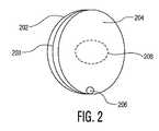
本発明のある態様によれば、除細動器10が訓練モードである場合、例えば図2の平面図に記載される電極200のような訓練用電極は、電極インタフェース17に電気結合される及び/又はこのインタフェースに応答する。訓練用電極は好ましくはさらに、除細動器10に対して、約1kΩのインピーダンスを持つ抵抗装置207、例えば抵抗器と直列に配される。抵抗器207は、電極の複素インピーダンスレベルの実数成分を約25〜500Ωである患者のインピーダンスレベルより上に上げることにより、電極200を治療用電極ではなく、訓練用電極であると識別するのを容易にする。電極200を訓練用電極であると識別することは、電極200による偶発的な電撃(ショック)を防ぐのに重要である。電極200と除細動器10との通信は、例えばリード線206のような1つ以上の通信路を介して行われてもよい。これが安全性を提供する。これらパッドが間違って貼られたり又は貼られなかったりする場合、除細動器は高電圧のショックを施さない。 According to certain aspects of the invention, when the
示されるように、例えば湾曲した縁部を持つ概ね矩形の形状のような如何なる適切な形状又は形状の組み合わせが可能であったとしても、電極は楕円形状である。電極200は好ましくは(その縁部が示される)上面202、底面204及び内層203を有する。 As shown, the electrode is elliptical, although any suitable shape or combination of shapes is possible, such as a generally rectangular shape with curved edges. The
よく知られるように、上面202は、絶縁、支持又は保護のカバー(図示せず)を含み、これはフレキシブルでもよく、被験者上に電極200の適切な配置を図で示してもよい。 As is well known, the
底面204は好ましくは、約0.020から0.040インチ(0.05から0.10cm)の厚さを持つ導電性の付着層、例えばゲル又は接着層により規定される。適切な導電性付着層はヒドロゲルである。適切なヒドロゲル製品は、Katecho, Inc社.の部品番号KM30Gから商業的に入手可能である。 The
内部では、電極200は、上面202と底面204との間に挿入される導電性フォイル層203を含む。導電性フォイル層203は好ましくは、そこに直径約3.81cmの開口、例えば穴208を有してもよい。穴208は、よく知られる方法及び技術を用いて、導電性フォイル層203から切り取られ、打ち抜かれ又は穿孔されてもよい。穴208は、電極200が剥離ライナー(release liner)の一方又は両面上に置かれる場合、高レベルのパッド間又はパッド−ライナー間のインピーダンスを供給するように動作する。電極が2つある場合、ゲルはこのライナーの中心にある穴を介して接触する。 Inside, the
本発明の他の態様によれば、除細動器10は好ましくは、訓練用の被験者に1つ以上の訓練用電極、例えば電極200を配置する前に、訓練モードで動作している。図3は、任意の他のパッケージング308を含む、剥離ライナー304上に配される電極200の透視図である。 In accordance with another aspect of the present invention,
任意のパッケージング308は、例えば電極200のような電極を除細動器10に接続するための電気インタフェースを持つハウジングを有してもよい。除細動器10による訓練用電極の識別を容易にするために、カートリッジ識別子380がパッケージング308に含まれてもよい。パッケージング308は如何なる適切な方法により実装されてもよい。
剥離ライナー304は、非導電性及び不粘着性の材料、例えばシリコンコーティングされた紙、ポリエステル、ポリプロピレン、ポリエチレン及び/又は他の不粘着性材料の1つ以上の層から、当業者に十分理解される方法で構成されてもよい。剥離ライナー304は好ましくはそこに直径約1.27cmの開口、例えば穴322を持つ。穴322は、よく知られる方法及び技術を用いて、剥離ライナー304から切り取られ、打ち抜かれ又は穿孔されてもよい。本発明の幾つかの態様と共に用いるのに適した様々な剥離ライナー構造の実施例は、米国特許公開番号US2003/0055478に示され、この明細書は参照することによりここに含まれるものとする。
電極200は好ましくは、除細動器10が電極200に電気的に結合されている場合、除細動器10は、電極200を含む電気路に沿って電気接続性の程度を特徴付け及び/又は識別する(例えばインピーダンス測定を行いインピーダンスレベルを測定する)ようなやり方で剥離ライナー304上に置かれる。電極200が剥離ライナー304及び/又は除細動器10に電気的に結合する様式は、電極200を含む多数の特徴的な電気路を決めることがわかる。
示されるように、電極200の底面204は、穴208(不可視)及び導電性付着層が穴322の上に置かれる上記様式で剥離ライナー304上に配される。抵抗器207と直列に接続されるリード線206は、任意の硬質電極パッケージ308に取り付け可能である。除細動器10と電極200との間の電気結合はコネクタ360を介して生じる又はパッケージ308が無い場合、何らかの他の適切なコネクタを介して生じる。 As shown, the
識別可能な程度の電気接続性を有するある電気路は、電極200の導電性付着層が剥離ライナー304の穴322に接すると共に、電極200が除細動器と電気的に結合される場合に作り出される。実際には、この電気路は、(電極200と同じ要素を含むが図示されない)第2の電極を含み、この電極も両方の電極の導電性付着層が穴322を介して接するように、穴208及び導電性付着層が穴322の上に置かれる様式で、剥離ライナー304上に配される。剥離ライナー304上に1つ以上の電極をどのように配置することも可能であり、これが電極を1つ以上含む電気路に沿って電気接続性の程度を特徴付けすることを除細動器10に可能にさせることがわかる。 An electrical path having a discernable degree of electrical connectivity is created when the conductive adhesion layer of
パッケージ308が用いられる場合、識別可能な程度の電気接続性を持つ他の電気路は、(剥離ライナー304上に置かれる)電極200がパッケージ308に保管されると共に、パッケージ308が除細動器10と電気的に結合されている場合に作り出される。 If
図1から図3を参照してみると、訓練モードにおける通常の動作中、除細動器10は、治療モードでの除細動器10の動作を模擬操縦する訓練シーケンスによりオペレータを誘導する。本発明のある態様によれば、電極インタフェース17が例えば電極200のような訓練用電極に電気的に結合されると共に、この訓練用電極が例えば剥離ライナー304のような剥離ライナー上に置かれるが、オペレータが訓練用電極を訓練用の被験者に配置する前である場合、除細動器10は第1の訓練状態で動作可能である。1つの可能な第1の訓練状態は、オペレータが剥離ライナーから電極を取り外すのを待つことであり、他の可能な第1の訓練状態は、オペレータが例えばコンテナ308のような他のパッケージングから前記電極を取り外すのを待つことである。電気接続性に関する既定される程度の電気接続性又は変動性が電極を含む電気路に沿って起こる場合、除細動器10は、第1の訓練状態から第2の訓練状態へ進む。第2の訓練状態のある実施例は、オペレータがパッケージから電極を取り外すのを待つことであり、これはパッド間のインピーダンスの検出可能な変化を生じさせる。第2又は第3の訓練状態の他の実施例は、オペレータが剥離ライナーから1つ以上のパッドを取り外すのを待つことである。他の訓練状態は、ユーザが電極を訓練装置上に適切に置くまで待つことである。除細動器10のオペレータは、オペレータインタフェースにより、除細動器10が訓練状態を変更したことを知らされる。例えば、音声案内が剥離ライナー304から1つ以上の電極200が取り外されたことを知らせてもよいし及び/又は取り外された電極を訓練装置上に置くようにオペレータに命令してもよい。光の点滅又はディスプレイに書かれるテキストのような他の案内も除細動器10が訓練状態を変更したことを知らせるのに使用する。 Referring to FIGS. 1-3, during normal operation in the training mode, the
訓練状態の進行は好ましくは制御器18により実行又は協働され、状態識別子34は好ましくは、例えば電気路に沿ったインピーダンス測定を得ることにより、既定される程度の電気接続性を識別する。識別されたインピーダンスは、オペレータが訓練用電極を剥離ライナーから取り外した及び/又は剥離ライナーを何らかの任意のパッケージングから取り外したことを示す。例えば、2つの電極200が共通する剥離ライナー304に取り付けられる場合、開口322を介して電気的に接している前記電極の導電性付着層204を用いて、この導電性付着層を流れる電流は、開口322に関連する既定のインピーダンスを生じさせる。約2000Ωよりも大きいが、約15KΩよりは小さい範囲のインピーダンスは、1つ又は両方の電極200は剥離ライナー304上に残ったままであり、訓練状態の進行は起きていないことを示す。1つ又は両方の電極200が剥離ライナー304から取り外されたことを示す(例えばインピーダンスが無限大に近づく)インピーダンスは、制御器18を起動させて、除細動器10を第1の訓練状態から第2の訓練状態へ進行させる。 The progress of the training state is preferably performed or coordinated by the
何れかの任意のパッケージングから1つ以上の電極200を取り外すことは、電極間のインピーダンスの僅かな変化を測定することにより検出されることができる。電極パッドを扱う場合、パッド間のインピーダンスはノイズフロアよりも大きな変化を経験する。パッドがこれらパッケージから取り外されたときを検出するために、装置は、パッド間のインピーダンスの変化をモニタリング、識別及び強調する。これらのインピーダンスの変化が検出される場合、除細動器は次の訓練状態又は次の訓練案内に進行する。 Removing one or
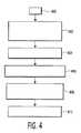
本発明の他の態様によれば、図1から図3を引き続き参照し、例えば除細動器10のような除細動器を使用するためにオペレータを訓練するための方法のフローチャートが図4に示されている。ブロック400で始まった後、ステップ402において、治療及び訓練モードの両方で動作可能であると共に、電極インタフェース17に結合され、剥離ライナー304のような剥離ライナー上に配される電極200のような電極に応答する例えば除細動器10のような体外式除細動器が設けられる。前記方法はステップ404に進み、ここでは訓練装置のような被験者上に電極を配置する前に、電極から入力信号が受信される。ステップ406において、電気接続性の程度が電極を含む電気路に沿って決められる。例えば電極200の導電性付着層が開口322と接しているかを示すインピーダンスが測定される。この決められた程度の電気接続性に基づいて、ステップ408において、体外式除細動器は、(例えば、オペレータが電極を剥離ライナーから取り外すのを待っている)第1の訓練状態から(例えばオペレータが前記電極を訓練装置に置くのを待っている)第2の訓練状態へ進行する。ステップ410において、除細動器が第1の訓練状態から第2の訓練状態へ進行したことを示す訓練状態の通知、例えば音声案内がオペレータに送られる。 In accordance with another aspect of the present invention, with continued reference to FIGS. 1-3, a flowchart of a method for training an operator to use a defibrillator, such as
本発明の上述した態様に従って訓練モードで動作する除細動器がそれに結合される訓練用電極がパッケージング及び/又は剥離ライナーから取り外された状態に達した後、これら訓練用電極は訓練装置に利用される。 After the defibrillator operating in the training mode according to the above-described aspects of the present invention has reached the state where the training electrode coupled thereto has been removed from the packaging and / or release liner, the training electrode is placed on the training device. Used.
本発明の他の態様によれば、図5は、(図1に示される)除細動器10及び(図2に示される)1つ以上の訓練用電極200を用いた特に有用な訓練装置500の階層式の透視図である。しかしながら、装置500は、如何なる形式の除細動器又は訓練用電極と共に使用するのにも適している。 In accordance with another aspect of the present invention, FIG. 5 illustrates a particularly useful training device using a defibrillator 10 (shown in FIG. 1) and one or more training electrodes 200 (shown in FIG. 2). FIG. 5 is a 500 perspective view. However, the
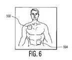
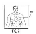
図5及び図1から図3も参照すると、装置500は透明な第1の層502を含む。層502は例えばポリエステル若しくは他の透明材料、又は電極200の導電性付着層の分離を可能にする約0.001から0.010インチ(0.0025から0.25cm)の範囲の適切な厚さのコーティングでもよい。示されるように、層502(及び以下に述べる後続する層)は、如何なる幾何学的形状が可能だとしても、矩形である。層502は好ましくは、例えば電極200を収容するようなサイズの開口のような1つ以上の電極付着領域504、506及び508を含む。ダイカッティング(die-cutting)、打ち抜き、切り取り、穿孔又は他の適切な方法若しくは技術を用いて1つ、2つ又は3つ何れかの開口が実際に置かれたとしても、3つの電極付着領域504、506及び508が示されている。電極付着領域504及び506は好ましくは、大人の除細動被験者の前面胴体上の電極の適切な配置に近いエリア(以下に詳細に説明される)に置かれ、電極付着領域508は好ましくは、子供の除細動被験者の前面胴体上の電極の適切な配置に近づくエリアに置かれる。これら電極付着領域はそこに取り付けるのに適する電極のサイズよりも小さくても又は大きくてもよい。 Referring also to FIGS. 5 and 1-3, the
第2の層510は、透明な第1の層502を介して識別可能である、大人の胴体又は子供の胴体のどちらかである除細動被験者の前面部分の二次元表示である。層510は印刷可能な用紙又はラベルでもよい。図6は、大人の胴体がそこに示されている第2の層510の実施例である。この大人の胴体は等身大でも又は他のサイズでもよい。図7は子供の胴体がそこに示されている第2の層510の実施例である。この子供の胴体は等身大でも又は他のサイズでもよい。層510は好ましくは、層502にある開口504、506及び508と同様なサイズ及び位置決めされる開口も含んでいる。図6に示されるように、開口504及び506は、大人の胴体から夫々成る胸骨及び尖部の位置に配され、この尖部の位置は、この胴体に巻きつけるように図示されてもよい。図7は、子供の胴体の略中間に置かれる開口508を説明する。 The
再び図5及び必要に応じて図1から図3を参照すると、第3の層512は信号線である。層512は、これら2つの電極が電極付着領域504及び506又は(以下にさらに説明される)508及び518に適切に位置決めされる場合、例えば電極200のような2つの電極間に通信路、例えば電気路を提供するように動作する。電極200が適切な電極付着領域に正しく置かれる場合、除細動器10は、電極間にある電気路にかかる既定される程度のインピーダンス(例えば開口208に関連するインピーダンス)を検出してもよく、十分知られた方法及び技術によりインピーダンスの検出に基づいて、訓練モードでの除細動器10のオペレータと対話してもよい。 Referring again to FIG. 5 and, optionally, FIGS. 1 to 3, the third layer 512 is a signal line. Layer 512 may be a communication path between two electrodes, such as
層512は、電極200の導電性付着層が存在する状態では腐食しない純粋な錫又は他の導電性材料でもよく、付着領域/開口504、506及び508を介して露出されてもよい。示されるように、層512は、層510及び(以下においてさらに説明される)514と同じ広がりを持ってもよいが、例えば依然としてある電極付着領域から他の電極付着領域へ延在する小さな長さ又は幅のような別の構成でもよい。代わりに、信号線は、電極付着領域504及び506又は(以下においてさらに説明される)508及び518の内部又はその周りにあるネットワーク化された個々の導体を介して生じてもよい。層510が大人の胴体を表すと共に、電極付着領域504及び506が共に層502上に形成される場合、層512は一方の面(例えば層502とは逆の面)においてポリエステル又は他の適当な材料と貼り合わされる。層510が子供の胴体を表す場合、層512は付加的に(例えば半分に)折り畳まれるので、導電面は二方向に位置決めされる。一方の方向は層502を向き、もう一方の方向は第4の層514を向いている。層512は、信号線を介して折り畳み数を最小にするように折り畳み可能又は屈曲可能である。 Layer 512 may be pure tin or other conductive material that does not corrode in the presence of the conductive adhesion layer of
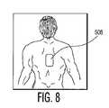
第4の層514は第3の層512を保護している。層510が大人の胴体を表す場合、層514は普通紙の層又は他の不導電性材料でもよく、装置500の背面として利用する。図8に示されるように、背面電極を配置する訓練が必要なときのために大人の背中又は背面ビューの二次元表示を示すために印刷される。層510が子供の胴体を表す場合、層514は好ましくは、透明な第5の層516を介して識別可能である子供の胴体の背面ビューの二次元表示であり、この層516は層502と同じ様式で構成及び構築され、電極付着領域508からオフセットされた電極付着領域518を含む。 The
ここで述べられる及び記載される実施例は、本質的には説明であることを意味し、様々な訓練装置、方法、システム及び除細動器がここで述べたような原理を用いて設計され、様々な商業的及び民生用用途に用いられてもよい。例えば、本発明の態様は、コンピュータプログラム又は信号処理方法の如何なる実施例にも限定されず、多数の記憶媒体、制御器/プロセッサ及び上記装置の構成も可能であることが分かる。その上、ここで述べた方法は、コンピュータソフトウェア、ファームウェア、ハードウェア(例えばアプリケーション専用の集積回路)又はそれらを組み合わせたものにより実施されてもよい。 The embodiments described and described herein are meant to be illustrative in nature, and various training devices, methods, systems and defibrillators have been designed using the principles as described herein. May be used in a variety of commercial and consumer applications. For example, it will be appreciated that aspects of the present invention are not limited to any embodiment of a computer program or signal processing method, and that numerous storage media, controllers / processors and apparatus configurations are possible. Moreover, the methods described herein may be implemented by computer software, firmware, hardware (eg, application specific integrated circuits), or a combination thereof.
Claims (17)
Translated fromJapanese−前記第1の電極を収容するようなサイズに開口を規定する第1の電極付着領域を有する透明層、
−前記第1の電極及び前記第2の電極が前記訓練装置上に配置される場合、前記第1の電極と前記第2の電極との間に通信を提供するように動作可能な転送路を有する、前記第1の電極付着領域の近くに配置される信号線、及び
−除細動被験者上に前記第1の電極の好ましい配置エリアを規定するやり方でその上に配される前記第1の電極付着領域を有する、前記透明層を介して識別可能である前記除細動被験者の前面部分の二次元表示
を有する訓練装置。In a training device for use with an external defibrillator responsive to a first electrode and a second electrode,
A transparent layer having a first electrode attachment region that defines an opening sized to accommodate the first electrode;
A transfer path operable to provide communication between the first electrode and the second electrode when the first electrode and the second electrode are disposed on the training device; A signal line disposed near the first electrode attachment region, and the first line disposed thereon in a manner that defines a preferred placement area of the first electrode on a defibrillation subject. A training device having a two-dimensional display of a front portion of the defibrillation subject having an electrode attachment region and identifiable through the transparent layer.
−前記転送路が動作している場合、前記体外式除細動器は、前記第1及び第2の電極と、前記訓練装置との間の接続状態を検出するように動作可能であるやり方で、前記第1の電極は前記第1の電極付着領域に配され、前記第2の電極は前記第2の電極付着領域に配される
請求項1に記載の訓練装置。The training apparatus according to claim 1, further comprising a second electrode attachment region that defines an opening with a size that accommodates the second electrode.
-When the transfer path is in operation, the external defibrillator is operable to detect a connection between the first and second electrodes and the training device. The training apparatus according to claim 1, wherein the first electrode is disposed in the first electrode attachment region, and the second electrode is disposed in the second electrode attachment region.
−前記シートの一方の面上における身体図、
−前記図上に適切な第1の除細動器電極の位置の描写、
−前記描写と、前記シート上における第2の除細動器電極の位置の第2の描写との間における導電路
を有する除細動器の訓練装置。A substantially flat plastic sheet with two faces;
-A body drawing on one side of the seat,
-A depiction of the position of the appropriate first defibrillator electrode on said figure,
A defibrillator training device having a conductive path between the representation and a second representation of the position of the second defibrillator electrode on the sheet.
Applications Claiming Priority (2)
| Application Number | Priority Date | Filing Date | Title |
|---|---|---|---|
| US54339904P | 2004-02-10 | 2004-02-10 | |
| PCT/IB2005/050408WO2005078682A1 (en) | 2004-02-10 | 2005-01-31 | External defibrillator training apparatus and method |
Publications (1)
| Publication Number | Publication Date |
|---|---|
| JP2007521875Atrue JP2007521875A (en) | 2007-08-09 |
Family
ID=34860417
Family Applications (1)
| Application Number | Title | Priority Date | Filing Date |
|---|---|---|---|
| JP2006551985APendingJP2007521875A (en) | 2004-02-10 | 2005-01-31 | External defibrillator training apparatus and method |
Country Status (5)
| Country | Link |
|---|---|
| US (1) | US8277223B2 (en) |
| EP (1) | EP1716551A1 (en) |
| JP (1) | JP2007521875A (en) |
| CN (1) | CN1918611A (en) |
| WO (1) | WO2005078682A1 (en) |
Cited By (3)
| Publication number | Priority date | Publication date | Assignee | Title |
|---|---|---|---|---|
| JP2014155793A (en)* | 2013-02-14 | 2014-08-28 | Heart Sign Technologies Ltd | Defibrillator electrode identification system |
| JP2016520366A (en)* | 2013-05-09 | 2016-07-14 | コーニンクレッカ フィリップス エヌ ヴェKoninklijke Philips N.V. | Defibrillator electrodes with adult and pediatric graphics |
| JP2018514266A (en)* | 2015-05-05 | 2018-06-07 | レールダル メディカル エー エスLaerdal Medical AS | Defibrillator training system |
Families Citing this family (7)
| Publication number | Priority date | Publication date | Assignee | Title |
|---|---|---|---|---|
| JP2007521875A (en)* | 2004-02-10 | 2007-08-09 | コーニンクレッカ フィリップス エレクトロニクス エヌ ヴィ | External defibrillator training apparatus and method |
| US9881521B2 (en)* | 2011-01-17 | 2018-01-30 | Prestan Products Llc | Manikin sensing pads and liners in an AED training system |
| US9368047B2 (en)* | 2013-04-22 | 2016-06-14 | The Johns Hopkins University | Simulation add-on device to allow anterior-posterior and/or anterior-lateral defibrillation |
| CN108136192A (en) | 2015-10-16 | 2018-06-08 | Zoll医疗公司 | For providing the dual sensor electrode of the recovery feedback of enhancing |
| US10373526B2 (en) | 2015-12-15 | 2019-08-06 | Physio-Control, Inc. | Automated external defibrillator (AED) trainer |
| CN106340220B (en)* | 2016-10-14 | 2023-03-21 | 青岛光电拿伦医疗设备有限公司 | Use method of practical teaching equipment of automatic external defibrillator |
| CN108153207A (en)* | 2018-02-12 | 2018-06-12 | 深圳讯丰通医疗股份有限公司 | A kind of AED training airplanes |
Citations (2)
| Publication number | Priority date | Publication date | Assignee | Title |
|---|---|---|---|---|
| JPH0336934U (en)* | 1989-08-24 | 1991-04-10 | ||
| JP2000093528A (en)* | 1998-09-15 | 2000-04-04 | Laerdal Medical As | System for communication between sensor of training device and defibrillator or electrode of training defibrillator |
Family Cites Families (46)
| Publication number | Priority date | Publication date | Assignee | Title |
|---|---|---|---|---|
| US1918041A (en)* | 1932-01-29 | 1933-07-11 | Knapke Fred | Rhythm maintaining device for artificial respiration |
| US2324702A (en)* | 1938-11-30 | 1943-07-20 | Karl F Hoffmann | Surgical simulacra and process of preparing same |
| US3895635A (en)* | 1973-06-20 | 1975-07-22 | Ndm Corp | Electrosurgical grounding cable assembly |
| US4323351A (en)* | 1979-12-26 | 1982-04-06 | Space Odyssey Ltd. | Visual display apparatus for the display of the autonomic nervous system and musculature and spinal nerves and related method |
| US4561851A (en)* | 1983-06-20 | 1985-12-31 | Biostim, Inc. | Apparatus for demonstrating and/or teaching alleviation of pain with transcutaneous electrical nerve stimulators |
| US4610254A (en)* | 1984-03-08 | 1986-09-09 | Physio-Control Corporation | Interactive portable defibrillator |
| US4588383A (en)* | 1984-04-30 | 1986-05-13 | The New Directions Group, Inc. | Interactive synthetic speech CPR trainer/prompter and method of use |
| US4583524A (en)* | 1984-11-21 | 1986-04-22 | Hutchins Donald C | Cardiopulmonary resuscitation prompting |
| US4863385A (en)* | 1987-01-05 | 1989-09-05 | Pierce Richard S | Cardiopulmonary resuscitation (CPR) sequencer |
| AU632647B2 (en)* | 1990-01-09 | 1993-01-07 | Physio-Control Corporation | Training electrode for use in defibrillator/monitor instruction and method of instruction |
| US5137458A (en)* | 1991-01-11 | 1992-08-11 | Physio-Control Corporation | Electrode placement training system |
| US5518406A (en)* | 1993-11-24 | 1996-05-21 | Waters; Tammie C. | Percutaneous endoscopic gastrostomy teaching device |
| US5494442A (en)* | 1994-10-27 | 1996-02-27 | Hecht; Marlene K. | Breast examination recording system |
| US5611815A (en) | 1994-12-08 | 1997-03-18 | Heartstream, Inc. | Defibrillator with training features |
| US5632623A (en)* | 1994-12-28 | 1997-05-27 | University Of Utah Research Foundation | Mock circulation system |
| US5479661A (en)* | 1995-01-03 | 1996-01-02 | Fingleson; Linda J. | Garment having printed instructions for self-examination of the breasts |
| US6319011B1 (en)* | 1995-04-06 | 2001-11-20 | Michael J. Motti | Automatic training defibrillator simulator and method |
| US5645571B1 (en) | 1995-08-01 | 1999-08-24 | Surviva Link Corp | Automated external defibrillator with lid activated self-test system |
| US5829984A (en)* | 1995-12-06 | 1998-11-03 | Kawai; Takeo | Chart for measurement of non-alignment characteristics and tilting direction type of skeleton |
| US6503087B1 (en)* | 1996-05-08 | 2003-01-07 | Gaumard Scientific, Inc. | Interactive education system for teaching patient care |
| US5993219A (en)* | 1996-11-05 | 1999-11-30 | Heartstream, Inc. | Method and apparatus for modifying a resuscitation training mannequin |
| US5720502A (en)* | 1996-11-08 | 1998-02-24 | Cain; John R. | Pain location and intensity communication apparatus and method |
| US5951598A (en)* | 1997-01-14 | 1999-09-14 | Heartstream, Inc. | Electrode system |
| USD409752S (en)* | 1997-01-14 | 1999-05-11 | Heartstream, Inc. | Electrode system |
| JP2893178B2 (en)* | 1997-09-01 | 1999-05-17 | 工業技術院長 | Biological optical phantom and method of manufacturing the same |
| US6154673A (en)* | 1997-12-30 | 2000-11-28 | Agilent Technologies, Inc. | Multilingual defibrillator |
| US6220866B1 (en)* | 1998-01-15 | 2001-04-24 | Eagle Simulation, Inc. | Electronic auscultation system for patient simulator |
| US5913686A (en)* | 1998-03-12 | 1999-06-22 | Vanwinkle; Tresa A. | Breast-mapping |
| US6115638A (en)* | 1998-05-04 | 2000-09-05 | Survivalink Corporation | Medical electrode with conductive release liner |
| JP2990602B1 (en)* | 1998-07-03 | 1999-12-13 | 株式会社京都科学 | Biopsy model |
| US6074213A (en) | 1998-08-17 | 2000-06-13 | Hon; David C. | Fractional process simulator with remote apparatus for multi-locational training of medical teams |
| US6178357B1 (en)* | 1998-08-28 | 2001-01-23 | Agilent Technologies, Inc. | Electrode pad system and defibrillator electrode pad that reduces the risk of peripheral shock |
| US6141584A (en)* | 1998-09-30 | 2000-10-31 | Agilent Technologies, Inc. | Defibrillator with wireless communications |
| US6360125B1 (en)* | 1998-12-21 | 2002-03-19 | Institute Of Critical Care Medicine | CPR protector |
| US6872080B2 (en)* | 1999-01-29 | 2005-03-29 | Cardiac Science, Inc. | Programmable AED-CPR training device |
| US7857626B2 (en)* | 2000-10-23 | 2010-12-28 | Toly Christopher C | Medical physiological simulator including a conductive elastomer layer |
| US6530783B1 (en)* | 2000-11-01 | 2003-03-11 | American Red Cross Of Greater Indianapolis | Cardiopulmonary resuscitation mannequin |
| US6560485B2 (en) | 2001-03-27 | 2003-05-06 | Koninklijke Philips Electronics N.V. | Four contact identification defibrillator electrode system |
| GB2377165B (en)* | 2001-07-06 | 2004-06-30 | Black & Decker Inc | Locking mechanism for dust collection module of vacuum cleaner |
| US20030028219A1 (en) | 2001-07-20 | 2003-02-06 | Powers Daniel J. | Modular medical device, base unit and module thereof, and automated external defibrillator (AED), methods for assembling and using the AED |
| US6694193B2 (en) | 2001-09-14 | 2004-02-17 | Koninklijke Philips Electronics N.V. | Medical electrode and release liner configurations facilitating packaged electrode characterization |
| EP1516600B1 (en) | 2001-09-18 | 2007-03-14 | Abbott Laboratories Vascular Enterprises Limited | Stent |
| US8527044B2 (en) | 2002-05-15 | 2013-09-03 | Physio-Control, Inc. | User interface method and apparatus for a medical device |
| KR20060111685A (en)* | 2004-02-10 | 2006-10-27 | 코닌클리케 필립스 일렉트로닉스 엔.브이. | External defibrillators with training mode and how to use such defibrillators |
| JP2007521875A (en)* | 2004-02-10 | 2007-08-09 | コーニンクレッカ フィリップス エレクトロニクス エヌ ヴィ | External defibrillator training apparatus and method |
| US7419376B2 (en)* | 2006-08-14 | 2008-09-02 | Artahn Laboratories, Inc. | Human tissue phantoms and methods for manufacturing thereof |
- 2005
- 2005-01-31JPJP2006551985Apatent/JP2007521875A/enactivePending
- 2005-01-31CNCNA2005800044066Apatent/CN1918611A/enactivePending
- 2005-01-31EPEP05702851Apatent/EP1716551A1/ennot_activeWithdrawn
- 2005-01-31WOPCT/IB2005/050408patent/WO2005078682A1/enactiveApplication Filing
- 2005-01-31USUS10/597,707patent/US8277223B2/enactiveActive
Patent Citations (2)
| Publication number | Priority date | Publication date | Assignee | Title |
|---|---|---|---|---|
| JPH0336934U (en)* | 1989-08-24 | 1991-04-10 | ||
| JP2000093528A (en)* | 1998-09-15 | 2000-04-04 | Laerdal Medical As | System for communication between sensor of training device and defibrillator or electrode of training defibrillator |
Cited By (3)
| Publication number | Priority date | Publication date | Assignee | Title |
|---|---|---|---|---|
| JP2014155793A (en)* | 2013-02-14 | 2014-08-28 | Heart Sign Technologies Ltd | Defibrillator electrode identification system |
| JP2016520366A (en)* | 2013-05-09 | 2016-07-14 | コーニンクレッカ フィリップス エヌ ヴェKoninklijke Philips N.V. | Defibrillator electrodes with adult and pediatric graphics |
| JP2018514266A (en)* | 2015-05-05 | 2018-06-07 | レールダル メディカル エー エスLaerdal Medical AS | Defibrillator training system |
Also Published As
| Publication number | Publication date |
|---|---|
| EP1716551A1 (en) | 2006-11-02 |
| WO2005078682A1 (en) | 2005-08-25 |
| US8277223B2 (en) | 2012-10-02 |
| US20090029332A1 (en) | 2009-01-29 |
| CN1918611A (en) | 2007-02-21 |
Similar Documents
| Publication | Publication Date | Title |
|---|---|---|
| US7715913B1 (en) | External defibrillator with training mode and method of use | |
| US6115638A (en) | Medical electrode with conductive release liner | |
| JP5108527B2 (en) | Automatic external defibrillator for adult and pediatric patients | |
| EP2035087B1 (en) | Electrode package attached to exterior of defibrillator | |
| US8676311B2 (en) | Memory device associated with defibrillation electrodes | |
| WO1994027674A1 (en) | Defibrillator with self-test features | |
| JP2007521875A (en) | External defibrillator training apparatus and method | |
| US7590456B2 (en) | Triangular or crescent shaped defibrillation electrode | |
| US8996138B2 (en) | Breakaway electrical connections for defibrillation electrode package | |
| KR102439035B1 (en) | defibrillation training system | |
| US9084880B2 (en) | Condition sensor for medical device package | |
| JP6054989B2 (en) | Iontophoresis patch | |
| AU687069C (en) | Defibrillator with self-test features |
Legal Events
| Date | Code | Title | Description |
|---|---|---|---|
| A621 | Written request for application examination | Free format text:JAPANESE INTERMEDIATE CODE: A621 Effective date:20080130 | |
| A131 | Notification of reasons for refusal | Free format text:JAPANESE INTERMEDIATE CODE: A131 Effective date:20100511 | |
| A02 | Decision of refusal | Free format text:JAPANESE INTERMEDIATE CODE: A02 Effective date:20101104 |