JP2007520292A - Implants for releasing active substances into the vascular fluid flow - Google Patents
Implants for releasing active substances into the vascular fluid flowDownload PDFInfo
- Publication number
- JP2007520292A JP2007520292AJP2006551814AJP2006551814AJP2007520292AJP 2007520292 AJP2007520292 AJP 2007520292AJP 2006551814 AJP2006551814 AJP 2006551814AJP 2006551814 AJP2006551814 AJP 2006551814AJP 2007520292 AJP2007520292 AJP 2007520292A
- Authority
- JP
- Japan
- Prior art keywords
- implant
- substrate
- active substance
- implant according
- body fluid
- Prior art date
- Legal status (The legal status is an assumption and is not a legal conclusion. Google has not performed a legal analysis and makes no representation as to the accuracy of the status listed.)
- Granted
Links
- 239000007943implantSubstances0.000titleclaimsabstractdescription105
- 239000013543active substanceSubstances0.000titleclaimsabstractdescription94
- 230000002792vascularEffects0.000titledescription4
- 239000012530fluidSubstances0.000title1
- 239000000758substrateSubstances0.000claimsabstractdescription79
- 210000001124body fluidAnatomy0.000claimsabstractdescription40
- 239000010839body fluidSubstances0.000claimsabstractdescription27
- 239000000463materialSubstances0.000claimsabstractdescription12
- 229910000861Mg alloyInorganic materials0.000claimsdescription21
- 229910045601alloyInorganic materials0.000claimsdescription20
- 239000000956alloySubstances0.000claimsdescription20
- 239000011248coating agentSubstances0.000claimsdescription12
- 238000000576coating methodMethods0.000claimsdescription12
- WHXSMMKQMYFTQS-UHFFFAOYSA-NLithiumChemical compound[Li]WHXSMMKQMYFTQS-UHFFFAOYSA-N0.000claimsdescription7
- QCWXUUIWCKQGHC-UHFFFAOYSA-NZirconiumChemical compound[Zr]QCWXUUIWCKQGHC-UHFFFAOYSA-N0.000claimsdescription7
- XAGFODPZIPBFFR-UHFFFAOYSA-NaluminiumChemical compound[Al]XAGFODPZIPBFFR-UHFFFAOYSA-N0.000claimsdescription7
- 229910052744lithiumInorganic materials0.000claimsdescription7
- 229910052726zirconiumInorganic materials0.000claimsdescription7
- XEEYBQQBJWHFJM-UHFFFAOYSA-NIronChemical compound[Fe]XEEYBQQBJWHFJM-UHFFFAOYSA-N0.000claimsdescription6
- 229910052782aluminiumInorganic materials0.000claimsdescription6
- 229910052761rare earth metalInorganic materials0.000claimsdescription6
- 150000002910rare earth metalsChemical class0.000claimsdescription6
- 229910052727yttriumInorganic materials0.000claimsdescription6
- VWQVUPCCIRVNHF-UHFFFAOYSA-Nyttrium atomChemical compound[Y]VWQVUPCCIRVNHF-UHFFFAOYSA-N0.000claimsdescription6
- 206010028980NeoplasmDiseases0.000claimsdescription4
- 238000012377drug deliveryMethods0.000claimsdescription4
- FYYHWMGAXLPEAU-UHFFFAOYSA-NMagnesiumChemical compound[Mg]FYYHWMGAXLPEAU-UHFFFAOYSA-N0.000claimsdescription3
- 239000011777magnesiumSubstances0.000claimsdescription3
- 229910000640Fe alloyInorganic materials0.000claimsdescription2
- 229910001080W alloyInorganic materials0.000claimsdescription2
- 238000007373indentationMethods0.000claimsdescription2
- 238000002560therapeutic procedureMethods0.000claims1
- 238000002513implantationMethods0.000description20
- 239000011159matrix materialSubstances0.000description18
- 238000013461designMethods0.000description12
- 238000011282treatmentMethods0.000description11
- 210000004204blood vesselAnatomy0.000description9
- 238000004873anchoringMethods0.000description7
- 239000004480active ingredientSubstances0.000description6
- 230000015556catabolic processEffects0.000description6
- 238000006731degradation reactionMethods0.000description6
- 230000000694effectsEffects0.000description5
- 238000000034methodMethods0.000description5
- 239000000470constituentSubstances0.000description4
- 239000000203mixtureSubstances0.000description4
- 239000000243solutionSubstances0.000description4
- 239000000126substanceSubstances0.000description4
- 239000011800void materialSubstances0.000description4
- 238000006065biodegradation reactionMethods0.000description3
- 238000010828elutionMethods0.000description3
- 239000010408filmSubstances0.000description3
- RVTZCBVAJQQJTK-UHFFFAOYSA-Noxygen(2-);zirconium(4+)Chemical compound[O-2].[O-2].[Zr+4]RVTZCBVAJQQJTK-UHFFFAOYSA-N0.000description3
- KIUKXJAPPMFGSW-DNGZLQJQSA-N(2S,3S,4S,5R,6R)-6-[(2S,3R,4R,5S,6R)-3-Acetamido-2-[(2S,3S,4R,5R,6R)-6-[(2R,3R,4R,5S,6R)-3-acetamido-2,5-dihydroxy-6-(hydroxymethyl)oxan-4-yl]oxy-2-carboxy-4,5-dihydroxyoxan-3-yl]oxy-5-hydroxy-6-(hydroxymethyl)oxan-4-yl]oxy-3,4,5-trihydroxyoxane-2-carboxylic acidChemical compoundCC(=O)N[C@H]1[C@H](O)O[C@H](CO)[C@@H](O)[C@@H]1O[C@H]1[C@H](O)[C@@H](O)[C@H](O[C@H]2[C@@H]([C@@H](O[C@H]3[C@@H]([C@@H](O)[C@H](O)[C@H](O3)C(O)=O)O)[C@H](O)[C@@H](CO)O2)NC(C)=O)[C@@H](C(O)=O)O1KIUKXJAPPMFGSW-DNGZLQJQSA-N0.000description2
- 201000010099diseaseDiseases0.000description2
- 208000037265diseases, disorders, signs and symptomsDiseases0.000description2
- 238000001035dryingMethods0.000description2
- 239000011796hollow space materialSubstances0.000description2
- 229920002674hyaluronanPolymers0.000description2
- 229960003160hyaluronic acidDrugs0.000description2
- 238000001727in vivoMethods0.000description2
- 238000002347injectionMethods0.000description2
- 239000007924injectionSubstances0.000description2
- 238000004519manufacturing processMethods0.000description2
- 238000012986modificationMethods0.000description2
- 230000004048modificationEffects0.000description2
- 239000010409thin filmSubstances0.000description2
- 229910000838Al alloyInorganic materials0.000description1
- 208000037273Pathologic ProcessesDiseases0.000description1
- 208000007536ThrombosisDiseases0.000description1
- 230000001028anti-proliverative effectEffects0.000description1
- 238000013459approachMethods0.000description1
- 229920002988biodegradable polymerPolymers0.000description1
- 239000004621biodegradable polymerSubstances0.000description1
- 230000015572biosynthetic processEffects0.000description1
- 239000008280bloodSubstances0.000description1
- 210000004369bloodAnatomy0.000description1
- 230000017531blood circulationEffects0.000description1
- 238000007664blowingMethods0.000description1
- 230000000747cardiac effectEffects0.000description1
- 238000000354decomposition reactionMethods0.000description1
- 239000007857degradation productSubstances0.000description1
- 238000010586diagramMethods0.000description1
- 238000007598dipping methodMethods0.000description1
- 238000009513drug distributionMethods0.000description1
- 230000002349favourable effectEffects0.000description1
- 230000035876healingEffects0.000description1
- 230000001771impaired effectEffects0.000description1
- 238000010348incorporationMethods0.000description1
- 229910052742ironInorganic materials0.000description1
- 238000013532laser treatmentMethods0.000description1
- 210000001365lymphatic vesselAnatomy0.000description1
- 229910052749magnesiumInorganic materials0.000description1
- 229940126601medicinal productDrugs0.000description1
- 239000013081microcrystalSubstances0.000description1
- HLXZNVUGXRDIFK-UHFFFAOYSA-Nnickel titaniumChemical compound[Ti].[Ti].[Ti].[Ti].[Ti].[Ti].[Ti].[Ti].[Ti].[Ti].[Ti].[Ni].[Ni].[Ni].[Ni].[Ni].[Ni].[Ni].[Ni].[Ni].[Ni].[Ni].[Ni].[Ni].[Ni]HLXZNVUGXRDIFK-UHFFFAOYSA-N0.000description1
- 229910001000nickel titaniumInorganic materials0.000description1
- 231100000956nontoxicityToxicity0.000description1
- 230000000399orthopedic effectEffects0.000description1
- 230000009054pathological processEffects0.000description1
- 230000000144pharmacologic effectEffects0.000description1
- 230000001766physiological effectEffects0.000description1
- 229920000642polymerPolymers0.000description1
- 238000012545processingMethods0.000description1
- 238000000518rheometryMethods0.000description1
- 238000000926separation methodMethods0.000description1
- 239000007787solidSubstances0.000description1
- 208000024891symptomDiseases0.000description1
- 238000007910systemic administrationMethods0.000description1
- WFKWXMTUELFFGS-UHFFFAOYSA-NtungstenChemical compound[W]WFKWXMTUELFFGS-UHFFFAOYSA-N0.000description1
- 229910052721tungstenInorganic materials0.000description1
- 239000010937tungstenSubstances0.000description1
- 230000003966vascular damageEffects0.000description1
Images


Classifications
- A—HUMAN NECESSITIES
- A61—MEDICAL OR VETERINARY SCIENCE; HYGIENE
- A61L—METHODS OR APPARATUS FOR STERILISING MATERIALS OR OBJECTS IN GENERAL; DISINFECTION, STERILISATION OR DEODORISATION OF AIR; CHEMICAL ASPECTS OF BANDAGES, DRESSINGS, ABSORBENT PADS OR SURGICAL ARTICLES; MATERIALS FOR BANDAGES, DRESSINGS, ABSORBENT PADS OR SURGICAL ARTICLES
- A61L31/00—Materials for other surgical articles, e.g. stents, stent-grafts, shunts, surgical drapes, guide wires, materials for adhesion prevention, occluding devices, surgical gloves, tissue fixation devices
- A61L31/02—Inorganic materials
- A61L31/022—Metals or alloys
- A—HUMAN NECESSITIES
- A61—MEDICAL OR VETERINARY SCIENCE; HYGIENE
- A61L—METHODS OR APPARATUS FOR STERILISING MATERIALS OR OBJECTS IN GENERAL; DISINFECTION, STERILISATION OR DEODORISATION OF AIR; CHEMICAL ASPECTS OF BANDAGES, DRESSINGS, ABSORBENT PADS OR SURGICAL ARTICLES; MATERIALS FOR BANDAGES, DRESSINGS, ABSORBENT PADS OR SURGICAL ARTICLES
- A61L31/00—Materials for other surgical articles, e.g. stents, stent-grafts, shunts, surgical drapes, guide wires, materials for adhesion prevention, occluding devices, surgical gloves, tissue fixation devices
- A61L31/08—Materials for coatings
- A—HUMAN NECESSITIES
- A61—MEDICAL OR VETERINARY SCIENCE; HYGIENE
- A61L—METHODS OR APPARATUS FOR STERILISING MATERIALS OR OBJECTS IN GENERAL; DISINFECTION, STERILISATION OR DEODORISATION OF AIR; CHEMICAL ASPECTS OF BANDAGES, DRESSINGS, ABSORBENT PADS OR SURGICAL ARTICLES; MATERIALS FOR BANDAGES, DRESSINGS, ABSORBENT PADS OR SURGICAL ARTICLES
- A61L31/00—Materials for other surgical articles, e.g. stents, stent-grafts, shunts, surgical drapes, guide wires, materials for adhesion prevention, occluding devices, surgical gloves, tissue fixation devices
- A61L31/14—Materials characterised by their function or physical properties, e.g. injectable or lubricating compositions, shape-memory materials, surface modified materials
- A61L31/148—Materials at least partially resorbable by the body
- A—HUMAN NECESSITIES
- A61—MEDICAL OR VETERINARY SCIENCE; HYGIENE
- A61L—METHODS OR APPARATUS FOR STERILISING MATERIALS OR OBJECTS IN GENERAL; DISINFECTION, STERILISATION OR DEODORISATION OF AIR; CHEMICAL ASPECTS OF BANDAGES, DRESSINGS, ABSORBENT PADS OR SURGICAL ARTICLES; MATERIALS FOR BANDAGES, DRESSINGS, ABSORBENT PADS OR SURGICAL ARTICLES
- A61L31/00—Materials for other surgical articles, e.g. stents, stent-grafts, shunts, surgical drapes, guide wires, materials for adhesion prevention, occluding devices, surgical gloves, tissue fixation devices
- A61L31/14—Materials characterised by their function or physical properties, e.g. injectable or lubricating compositions, shape-memory materials, surface modified materials
- A61L31/16—Biologically active materials, e.g. therapeutic substances
- A—HUMAN NECESSITIES
- A61—MEDICAL OR VETERINARY SCIENCE; HYGIENE
- A61F—FILTERS IMPLANTABLE INTO BLOOD VESSELS; PROSTHESES; DEVICES PROVIDING PATENCY TO, OR PREVENTING COLLAPSING OF, TUBULAR STRUCTURES OF THE BODY, e.g. STENTS; ORTHOPAEDIC, NURSING OR CONTRACEPTIVE DEVICES; FOMENTATION; TREATMENT OR PROTECTION OF EYES OR EARS; BANDAGES, DRESSINGS OR ABSORBENT PADS; FIRST-AID KITS
- A61F2/00—Filters implantable into blood vessels; Prostheses, i.e. artificial substitutes or replacements for parts of the body; Appliances for connecting them with the body; Devices providing patency to, or preventing collapsing of, tubular structures of the body, e.g. stents
- A61F2/82—Devices providing patency to, or preventing collapsing of, tubular structures of the body, e.g. stents
- A61F2/86—Stents in a form characterised by the wire-like elements; Stents in the form characterised by a net-like or mesh-like structure
- A—HUMAN NECESSITIES
- A61—MEDICAL OR VETERINARY SCIENCE; HYGIENE
- A61F—FILTERS IMPLANTABLE INTO BLOOD VESSELS; PROSTHESES; DEVICES PROVIDING PATENCY TO, OR PREVENTING COLLAPSING OF, TUBULAR STRUCTURES OF THE BODY, e.g. STENTS; ORTHOPAEDIC, NURSING OR CONTRACEPTIVE DEVICES; FOMENTATION; TREATMENT OR PROTECTION OF EYES OR EARS; BANDAGES, DRESSINGS OR ABSORBENT PADS; FIRST-AID KITS
- A61F2210/00—Particular material properties of prostheses classified in groups A61F2/00 - A61F2/26 or A61F2/82 or A61F9/00 or A61F11/00 or subgroups thereof
- A61F2210/0004—Particular material properties of prostheses classified in groups A61F2/00 - A61F2/26 or A61F2/82 or A61F9/00 or A61F11/00 or subgroups thereof bioabsorbable
- A—HUMAN NECESSITIES
- A61—MEDICAL OR VETERINARY SCIENCE; HYGIENE
- A61F—FILTERS IMPLANTABLE INTO BLOOD VESSELS; PROSTHESES; DEVICES PROVIDING PATENCY TO, OR PREVENTING COLLAPSING OF, TUBULAR STRUCTURES OF THE BODY, e.g. STENTS; ORTHOPAEDIC, NURSING OR CONTRACEPTIVE DEVICES; FOMENTATION; TREATMENT OR PROTECTION OF EYES OR EARS; BANDAGES, DRESSINGS OR ABSORBENT PADS; FIRST-AID KITS
- A61F2250/00—Special features of prostheses classified in groups A61F2/00 - A61F2/26 or A61F2/82 or A61F9/00 or A61F11/00 or subgroups thereof
- A61F2250/0058—Additional features; Implant or prostheses properties not otherwise provided for
- A61F2250/0067—Means for introducing or releasing pharmaceutical products into the body
- A61F2250/0068—Means for introducing or releasing pharmaceutical products into the body the pharmaceutical product being in a reservoir
- A—HUMAN NECESSITIES
- A61—MEDICAL OR VETERINARY SCIENCE; HYGIENE
- A61L—METHODS OR APPARATUS FOR STERILISING MATERIALS OR OBJECTS IN GENERAL; DISINFECTION, STERILISATION OR DEODORISATION OF AIR; CHEMICAL ASPECTS OF BANDAGES, DRESSINGS, ABSORBENT PADS OR SURGICAL ARTICLES; MATERIALS FOR BANDAGES, DRESSINGS, ABSORBENT PADS OR SURGICAL ARTICLES
- A61L2300/00—Biologically active materials used in bandages, wound dressings, absorbent pads or medical devices
- A61L2300/60—Biologically active materials used in bandages, wound dressings, absorbent pads or medical devices characterised by a special physical form
- A61L2300/602—Type of release, e.g. controlled, sustained, slow
- A61L2300/604—Biodegradation
Landscapes
- Health & Medical Sciences (AREA)
- Life Sciences & Earth Sciences (AREA)
- General Health & Medical Sciences (AREA)
- Animal Behavior & Ethology (AREA)
- Veterinary Medicine (AREA)
- Public Health (AREA)
- Epidemiology (AREA)
- Heart & Thoracic Surgery (AREA)
- Surgery (AREA)
- Vascular Medicine (AREA)
- Chemical & Material Sciences (AREA)
- Molecular Biology (AREA)
- Engineering & Computer Science (AREA)
- Medicinal Chemistry (AREA)
- Biomedical Technology (AREA)
- Inorganic Chemistry (AREA)
- Materials For Medical Uses (AREA)
- Prostheses (AREA)
- Medicinal Preparation (AREA)
Abstract
Translated fromJapaneseDescription
Translated fromJapanese本発明は、体液が流れる脈管中に活性物質を放出するためのインプラント及びこのようなインプラントの適用に関係する。 The present invention relates to an implant for releasing an active substance into a vessel through which bodily fluids flow and the application of such an implant.
何世紀もの間、人は、医療用の活性物質の標的投与により病的過程及び状態の治癒を促進し、そして疾患に伴う症状の軽減を試みてきた。適切な活性物質の選択と探索の他に、残されている問題の1つは、治療を必要とする部位において活性物質を利用できるようにすることである。投与に伴う副作用を最小限にするために、可能であれば、活性物質の放出はもっぱら治療部位に限定されるべきである。さらに、殆どの場合に、効果を最適にするために、可能な限り正確に投与量を維持すること、すなわち、予定の時間内で治療部位における活性物質の量を特定の範囲内に維持することが必要である。一般的には、活性物質は経口、皮下、静脈内又は直腸に適用される。医薬品の通常の全身投与は、特に局所的疾患、例えば腫瘍の場合には顕著な合併症を生じる。 For centuries, humans have attempted to promote healing of pathological processes and conditions through targeted administration of medical active substances and to alleviate symptoms associated with the disease. In addition to selecting and searching for an appropriate active agent, one remaining problem is making the active agent available at the site that requires treatment. In order to minimize side effects associated with administration, the release of the active substance should be restricted exclusively to the treatment site, if possible. Furthermore, in most cases, to optimize the effect, maintain the dose as accurately as possible, i.e. maintain the amount of active substance at the treatment site within a certain range within the scheduled time. is required. In general, the active substance is applied orally, subcutaneously, intravenously or rectally. Normal systemic administration of medicinal products results in significant complications, especially in the case of local diseases such as tumors.
そのために、この数年間、治療を受ける患者の体内に活性物質をより特異的に導入するための試みが盛んになっている。用語「局所薬物送達」(Local Drug Delivery(LDD))は、インプラントによる限定的(exclusively)局所治療、すなわち本質的にインプラントを直に取り囲む組織のみへの活性物質の溶出を記述するために設けられた。したがって、活性物質がその薬理作用を発揮する治療部位は埋め込み部位に直に接している。 For this reason, attempts have been made to introduce more specifically active substances into the body of patients undergoing treatment in the last few years. The term “local drug delivery” (LDD) is provided to describe the exclusive local treatment with an implant, ie the elution of an active substance only into the tissue that essentially directly surrounds the implant. It was. Therefore, the treatment site where the active substance exerts its pharmacological action is in direct contact with the implantation site.
したがって、LDDシステムのための重要な応用分野は、ステント、心臓ペースメーカー又は整形外科の人工関節などの永続的なインプラントの生体適合性の改善にある。特に、インプラントの存在や埋め込みによる合併症は減少させるか或いは避けなければならない。 Thus, an important field of application for LDD systems is in improving the biocompatibility of permanent implants such as stents, cardiac pacemakers or orthopedic joints. In particular, the presence of implants and complications due to implantation must be reduced or avoided.
上記のLDDシステムと異なる活性物質の投与の背後にあり、本発明にも応用されている基本的コンセプトは、埋め込みの部位と治療の部位の間のより明瞭な空間的分離を提供することである。言い換えると、身体に導入された後に、インプラント上で放出された活性物質は直接(局所的に)作用せずに、インプラントから空間的に離れた組織の局部においてその作用を発揮する。用語「局部薬物送達」(Regional Drug Delivery)即ち簡略して言うとRDDは、このタイプの局部的活性物質投与を記述するために以下で使用されるであろう。 The basic concept behind the administration of different active substances from the LDD system described above and applied to the present invention is to provide a clearer spatial separation between the implantation site and the treatment site . In other words, after being introduced into the body, the active substance released on the implant does not act directly (locally) but exerts its action in the local area of the tissue spatially remote from the implant. The term “Regional Drug Delivery”, or RDD for short, will be used below to describe this type of local active substance administration.
或る症状、例えば局所に限定された腫瘍において、治療すべき組織の脈管系を介して活性物質を投与することができる。この目的のために、治療部位の下流にある血管の中にインプラントを導入する必要がある。これの従来技術のアプローチは、例えば、活性物質を含有する重合体のマトリックスを血管の中に注入することである。このマトリックスは、注射後直ちに血管壁に接着する丈夫なフィルムに変化するように設計される。活性物質を含有するフィルムは徐々に分解し、活性物質を放出する。しかし、問題の血管にピンポイントの注入を行うのは実際上非常に困難であり、例えば血栓などの形成によるその他の合併症を生じる可能性がある。最後に、投与量もフィルムの厚さに依存する、すなわち、実際に生じる放出特性を予測することは困難である。 In certain conditions, such as locally confined tumors, the active substance can be administered via the vascular system of the tissue to be treated. For this purpose, it is necessary to introduce an implant into a blood vessel downstream of the treatment site. A prior art approach to this is, for example, injecting a polymer matrix containing the active substance into the blood vessel. This matrix is designed to turn into a strong film that adheres to the vessel wall immediately after injection. The film containing the active substance gradually degrades and releases the active substance. However, pinpoint injections into the blood vessels in question are very difficult in practice and can lead to other complications, for example due to the formation of a thrombus. Finally, the dosage also depends on the thickness of the film, i.e. it is difficult to predict the release characteristics that actually occur.
したがって、本発明の本質的目的は、体液が流れる脈管内に活性物質を放出するためのインプラントを供給することである。 Accordingly, the essential object of the present invention is to provide an implant for releasing an active substance into a vessel through which bodily fluids flow.
この目的は、請求項1に記載した特徴を持つインプラントにより達成される。体液が流れる脈管の中に活性成分を放出するためのインプラントは、放出される活性物質の基材として生分解性物質からなる基体を含み、その周囲を体液が内側及び/又は外側で循環することが特徴である。言い換えると、体液、特に血液はその埋め込みの後に極力遮断されずにインプラントの中を又はその周囲を流れる。インプラントの基体は、流れ去る体液の中に少なくとも可能な限り溶出されそして下位の治療部位に分配される活性物質の基材となる。インプラントの基体は時間の経過とともに分解される。 This object is achieved by an implant having the features of claim 1. An implant for releasing an active ingredient into a vessel through which bodily fluids flow comprises a substrate made of a biodegradable substance as a substrate for the released active substance, around which the bodily fluid circulates inside and / or outside It is a feature. In other words, bodily fluids, especially blood, flow through or around the implant without being blocked as much as possible after its implantation. The substrate of the implant is the substrate for the active substance that is at least as eluted as possible in the flowing body fluid and distributed to the underlying treatment site. The implant substrate degrades over time.
したがって、このインプラントは理想的には局部的薬物分配(RDD)の目的、特に腫瘍の治療に適する。このインプラントのこれらへの適用は別途請求される。 This implant is therefore ideally suited for the purpose of local drug distribution (RDD), especially for the treatment of tumors. Application of these implants to these is separately billed.
本発明の意図する範囲内において脈管とは、心臓と共に一つの機能単位を形成する末端流路の脈管を(広い意味ではリンパ管も)含む動脈及び静脈血管の全体のことである。本発明のインプラントは、脈管中を流れる体液中に活性物質を放出するように設計されている。したがって、活性物質は放出部位からさらに下流に存在する実際の作用部位へ供給される。したがって、インプラントは、活性物質、好ましくは使用した活性物質の少なくとも80重量%が脈管の中に放出されそして体液により運ばれるように設計されなければならない。血管壁の方向への放出は避けなければならない。したがって本発明では、埋め込みの後血管壁と接している領域は、活性物質の基材(substrates)とならないことが好ましい。例えば、インプラントが埋め込み後に脈管上にその外壁で支えられている管状形状である場合に、活性物質はその外壁と接触しない。 Within the intended scope of the present invention, a blood vessel refers to the whole of arterial and venous blood vessels, including the blood vessels of the end flow channels that form one functional unit with the heart (in a broad sense, also lymphatic vessels). The implant of the present invention is designed to release the active substance into bodily fluids flowing through the vessels. Thus, the active substance is supplied to the actual working site that is further downstream from the release site. The implant must therefore be designed such that at least 80% by weight of the active substance, preferably the active substance used, is released into the vessel and carried by body fluids. Release in the direction of the vessel wall must be avoided. Therefore, in the present invention, it is preferable that the region in contact with the blood vessel wall after implantation does not become a substrate of the active substance. For example, if the implant has a tubular shape that is supported on its outer wall on the vessel after implantation, the active substance does not contact the outer wall.
本発明の意味の範囲内の基体とは、生分解が始まるまではインプラントの機械的一体性を維持し、そして放出される活性物質の基材(substrates)となるか又は活性物質を含有するマトリックスとなるインプラントの構造物であると理解される。 A substrate within the meaning of the present invention means a matrix that maintains the mechanical integrity of the implant until biodegradation begins and serves as a substrate for active substances to be released or contains active substances. Is understood to be the structure of the implant.
体液が基体の中を流れるのみであるならば、両端の開いた管状基体として設計されることが好ましく、その基体は(埋め込まれたときに)その外側が血管壁に接している。血管の断面に合わせた形とするので、体液の乱れは大きく抑制されるか、或いは少なくとも減少させられるので、これらの種類のインプラントは体液の大容量が流れる脈管に特に適している。 If bodily fluids only flow through the substrate, it is preferably designed as an open tubular substrate at both ends, which substrate (when implanted) is in contact with the vessel wall on the outside. These types of implants are particularly suitable for vessels through which large volumes of bodily fluids flow, since the turbulence of bodily fluids is greatly suppressed or at least reduced due to the shape adapted to the cross-section of the blood vessel.
本発明のインプラントの第2の態様では、体液は基体の中又は周囲を通ってその内側と外側の両方を流れる。この目的のために、基体は流れの方向に入り口と出口が一列に並んだ中空の物体として設計することができる。埋め込みの直後又は短時間後に体液と接触するこの中空の物体は、特に、管状、シリンダー状又は球状のデザインにすることができる。インプラントの体内における相対的位置を確保するために、基体から血管壁へ伸び、支持体として寄与する、少なくとも大部分が生分解性である固定部が備え付けられる。 In the second aspect of the implant of the present invention, body fluid flows both inside and outside through or around the substrate. For this purpose, the substrate can be designed as a hollow object with inlets and outlets aligned in the direction of flow. This hollow object that comes into contact with bodily fluids immediately after implantation or after a short time can in particular have a tubular, cylindrical or spherical design. In order to ensure the relative position of the implant in the body, at least a largely biodegradable anchoring part is provided which extends from the substrate to the vessel wall and contributes as a support.
固定部は、例えば、ジグザグ形、フック又はうろこ様の外形を有することができる。固定部は、少なくとも活性物質の90重量%、特に95%重量%が放出される期間中インプラントが固定されていることを保証するように設計されなければならない。固定部の使用によりインプラントと血管壁の間の接触面積は減るので、内皮化の可能性のある領域も限定される。固定部の具体的設計は、なかんずく、埋め込み部位の流れの状態、活性物質の放出動態及び基体の分解特性に依存するので、インプラントは個別の応用に対してそれぞれ適合させられなければならない。この目的を達成するために、当業者は、基礎として、下記に関する一般的情報を利用することができるであろう。
‐ 身体中の脈管の流動学、
‐ その処理及びコーティングを含む材料の修飾又は合金の選択の生分解性材料の分解動態に対する影響、及び
‐ その修飾又はマトリックス中への取り込みの関数としての活性物質の放出動態に対する影響。The fixing part can have, for example, a zigzag shape, a hook or a scale-like shape. The anchoring part must be designed to ensure that the implant is anchored for a period during which at least 90% by weight of the active substance, in particular 95% by weight, is released. Since the use of the anchoring portion reduces the contact area between the implant and the vessel wall, the area of potential endothelialization is also limited. The specific design of the anchorage depends, inter alia, on the flow state of the implantation site, the release kinetics of the active substance and the degradation characteristics of the substrate, so that the implant must be individually adapted to the particular application. To achieve this goal, those skilled in the art will be able to utilize general information regarding the following as a basis.
-Vascular rheology in the body,
-The effect of the modification of the material, including its treatment and coating, or the choice of alloy on the degradation kinetics of the biodegradable material, and-the effect on the release kinetics of the active substance as a function of its modification or incorporation into the matrix.
製造上の理由から、固定部は同じ生分解性材料から作られていることが好ましく、基体に一体となって連結している。 For manufacturing reasons, the fixing part is preferably made of the same biodegradable material and is integrally connected to the substrate.
本発明のインプラントの第3の態様は、体液が基体を通って流れるだけのものである。言い換えると、基体は、基体の外壁のみが体液と接触する閉鎖構造を呈する。基体は詰まったデザインであるか、又は中空の基体の中に存在する基体の内壁は生分解の結果としてのみアクセス可能となる。特に、網状、先端を切った形又は薄膜状の基本的パターンを持つ基体が考えられる。これらの態様におけるインプラントの基体もまた上記の固定部によって脈管内に固定することができる。 A third aspect of the implant of the present invention is one in which bodily fluids only flow through the substrate. In other words, the base body has a closed structure in which only the outer wall of the base body is in contact with body fluid. The substrate is either a solid design or the inner wall of the substrate present in the hollow substrate is only accessible as a result of biodegradation. In particular, a substrate having a basic pattern of a net-like shape, a truncated shape or a thin-film shape is conceivable. The base of the implant in these embodiments can also be fixed in the vessel by the fixing part.
上記の閉鎖構造の好ましい態様は、基体が外側から内側へ多層構造を持つものである。放出される活性物質はそれぞれの層の間に存在する。身体の中で外側の層は最初に分解され、そしてその下の活性物質が放出される。次いで次の層が分解され、その層の下の活性物質が放出され、これが繰り返される。 In a preferred embodiment of the above-mentioned closed structure, the substrate has a multilayer structure from the outside to the inside. The active substance to be released is present between the respective layers. The outer layers in the body are first broken down and the active substance underneath is released. The next layer is then decomposed, releasing the active substance under that layer and this is repeated.
本発明の好ましい設計により、インプラントの基体は、少なくとも部分的に生分解性のマグネシウム、鉄又はタングステン合金から成る。これらの合金において、言及した元素は合金の少なくとも50重量%、特に70重量%、特に好ましくは80重量%の比率を示す。また特に好ましいのは、合金に希土類金属及びイットリウムが含有されているタイプWE、特にWE43のマグネシウム合金である。言及した合金は技術的に充分処理することができ、本発明のインプラントを実現するための理想的機械的材料特性を持ち、そして生体内において好ましい分解動態を示す。さらに、特にマグネシウム合金の場合に、基体の生分解の間に良い生理的効果が周囲の組織に生じるように思われる。 According to a preferred design of the invention, the implant substrate is at least partially composed of a biodegradable magnesium, iron or tungsten alloy. In these alloys, the elements mentioned represent a proportion of at least 50% by weight of the alloy, in particular 70% by weight, particularly preferably 80% by weight. Particularly preferred is a type WE, particularly a WE43 magnesium alloy, in which the alloy contains a rare earth metal and yttrium. The alloys mentioned can be technically well processed, have the ideal mechanical material properties for realizing the implants of the invention, and exhibit favorable degradation kinetics in vivo. Furthermore, it appears that good physiological effects occur in the surrounding tissue during substrate biodegradation, especially in the case of magnesium alloys.
さらに、予想されるその高い生体適合性の故に、1及び30重量%のリチウムを含有するマグネシウム合金は好ましい。また、処理性、機械的及び分解性に関係する性質の故に、0.1重量%から10重量%のアルミニウムを含有するマグネシウム合金及び0.01重量%から2重量%のジルコニウムを含有するマグネシウム合金も好ましい。言及したマグネシウム合金の構成成分−つまり、希土類金属(E)、イットリウム(W)、リチウム(L)、アルミニウム(A)及びジルコニウム(K)−はいずれかの組み合わせで合金の部分を形成することができ、合金構成成分の標準化された略号はASTMにしたがってカッコ内に示されている。例えば、以下のタイプの合金組成を使用することができる:LWE,AL,LAE及びLE、この文字の配列は使用される合金組成にしたがって入れ替えることができる。したがって、マグネシウム合金は、好ましくは希土類金属、イットリウム、リチウム、アルミニウム及びジルコニウムのグループの1又はそれ以上の合金成分を含有する。 Furthermore, due to its expected high biocompatibility, magnesium alloys containing 1 and 30% by weight lithium are preferred. Magnesium alloys containing 0.1 to 10% aluminum by weight and magnesium alloys containing 0.01 to 2% zirconium by weight due to properties related to processability, mechanical and degradability Is also preferable. The constituents of the magnesium alloy mentioned—that is, the rare earth metal (E), yttrium (W), lithium (L), aluminum (A) and zirconium (K) —can form part of the alloy in any combination. The standardized abbreviations for the alloy constituents are shown in parentheses according to ASTM. For example, the following types of alloy compositions can be used: LWE, AL, LAE and LE, the arrangement of this letter can be interchanged according to the alloy composition used. Thus, the magnesium alloy preferably contains one or more alloy components from the group of rare earth metals, yttrium, lithium, aluminum and zirconium.
またインプラントの基体は、好ましくは第1の膨張しない状態及び第2の膨張した状態をとることができるように設計される。このような構造を実現するために、先行技術の多数のステントのデザインが助けとなるが、本発明のインプラントにおけるこの態様では、血管壁に対する支持機能を示す必要はないし、或いは示してはならないことは特記する必要がある。インプラントが脈管内に固定されていること、すなわち体液の一定の流れにより運ばれて行かないことが保証されていることだけが必要である。したがって、設計の点で、支持機能を持つインプラントの場合よりも自由度がより大きい。例えば、活性物質が基体を覆うコーティングの一部を形成している場合には、体液に面している基体の部分領域は可能な限り大きな面積を持つように設計され、活性物質により覆われなければならない。内皮化、すなわち、インプラントの食い込みは、活性物質の溶出が障害されないことを前提として、許容することができる。必要があれば、相互に作用する物質は、例えば、インプラントの薄膜上の一定の表面構造により、又は内皮化過程によるコーティングにより影響を弱めなければならない。 Also, the implant substrate is preferably designed to be able to assume a first unexpanded state and a second expanded state. In order to achieve such a structure, a number of prior art stent designs can help, but this aspect of the implant of the present invention does not need or should show support for the vessel wall. Need special mention. It is only necessary that the implant is secured in the vessel, i.e. it is guaranteed not to be carried by a constant flow of body fluid. Therefore, in terms of design, the degree of freedom is greater than in the case of an implant having a support function. For example, if the active substance forms part of a coating covering the substrate, the partial area of the substrate facing the body fluid must be designed to have as large an area as possible and must be covered by the active substance. I must. Endothelialization, i.e., encroachment of the implant, can be tolerated provided that the elution of the active substance is not impaired. If necessary, the interacting substances must be weakened, for example, by a certain surface structure on the thin film of the implant or by coating by an endothelialization process.
好ましくは、その中を体液が流れる脈管の中に活性物質を放出するための本発明のインプラントは次のように設計される:
‐ 基体は、脈管に面する側の少なくとも一定の領域に、活性物質を含有するコーティングを有する、
‐ 基体は、活性物質を含有する一つ又はそれ以上の空所(cabity)を有する、及び/又は
‐ 基体は、活性成分を含有する一つ又はそれ以上の中空体を有する。Preferably, the implant of the present invention for releasing an active substance into a vessel through which body fluid flows is designed as follows:
The substrate has a coating containing the active substance in at least certain areas on the side facing the vessel,
The substrate has one or more cavities containing the active substance and / or the substrate has one or more hollow bodies containing the active ingredients.
したがって、第1の変形例は、基体が少なくとも部分的に活性成分でコートされているものである。ここで、コーティングは、活性物質そのもののみならず活性物質を含有する生分解性マトリックスからなるものでもよい。例えば、ヒアルロン酸又はその誘導体のマトリックス中に埋め込まれた活性物質が想定される。マトリックスの選択のみならず活性物質の投与の形態も、活性物質のインビボ放出動態に大きく影響する。高度な変動要因が放出動態に影響するので、放出動態は特定のシステムに対してのみ最適化することができる。好ましくは、コーティングの場所は、活性物質が脈管の中を流れる体液中に充分に放出され、隣接する血管壁の方向には放出されないように予め決定されていなければならないことも記述しなければならない。 Accordingly, the first variant is one in which the substrate is at least partially coated with an active ingredient. Here, the coating may consist of a biodegradable matrix containing not only the active substance itself but also the active substance. For example, an active substance embedded in a matrix of hyaluronic acid or its derivatives is envisaged. The mode of administration of the active substance as well as the choice of matrix greatly affects the in vivo release kinetics of the active substance. Since highly variable factors affect the release kinetics, the release kinetics can only be optimized for a specific system. Preferably, it should also be stated that the location of the coating must be predetermined so that the active substance is sufficiently released into the body fluid flowing through the vessel and not in the direction of the adjacent vessel wall. Don't be.
第2の変形例に従うと、活性物質を含有する空所を基体に組み込むことができる。本発明の意図する範囲において空所(cabity)とは、インプラントの基体の中のくぼみ(recesses)、割れ目(gaps)又はドリルで開けた穴のことであり、これは基体によって完全に閉鎖されていない、すなわち、少なくとも一方の側から接近することができる。活性物質は純粋な形で存在するか、又は空所側のマトリックス中に取り込まれている。このような空所の作成は、例えばステントの分野において充分に知られており、例えばレーザー処理により行うことができる。体液がその中又は周囲を流れる本発明のインプラントが、単にくぼみから活性物質を徐々に放出させることを述べるに過ぎない。この過程は、基体の分解が進行するにしたがって加速される。コーティングよりも遅い放出が一般的に期待される。 According to a second variant, a cavity containing the active substance can be incorporated into the substrate. For the purposes of the present invention, a cavity is a recess, gaps or drilled hole in the implant substrate that is completely closed by the substrate. Not accessible, ie accessible from at least one side. The active substance is present in pure form or is incorporated in the void side matrix. The creation of such voids is well known, for example, in the field of stents and can be performed, for example, by laser treatment. It is merely stated that the implants of the present invention in which bodily fluids flow in or around allow the active substance to be released gradually from the depression. This process is accelerated as the decomposition of the substrate proceeds. A slower release than the coating is generally expected.
最後に、本発明のインプラントのその他の変形例は、基体が活性物質を導入された中空体を1個又はそれ以上を含んでいるものである。ここでまた、活性物質は純粋な物質として存在するか又はマトリックスの中に埋め込まれている。キャビティ(cavities)は、基体によって完全に閉鎖され、その中に活性成分が予め導入されている空間である。活性物質は基体が徐々に分解することによってのみ利用可能となり流れ去る体液の中に溶解することができる。したがって、この変形例では一般的に、既に記述したいずれの種類に比較しても最も遅い活性物質の放出を示す。例えば、考えられる変形例では、活性物質を充填した中空ワイヤーで形成された基体が提供される。 Finally, another variant of the implant according to the invention is one in which the substrate contains one or more hollow bodies into which the active substance has been introduced. Here too, the active substance is present as a pure substance or embedded in a matrix. Cavities are spaces that are completely closed by the substrate and into which the active ingredient has been previously introduced. The active substance can only be used by the gradual degradation of the substrate and can be dissolved in the flowing body fluid. Therefore, this variant generally shows the slowest active substance release compared to any of the previously described types. For example, in a possible variant, a substrate formed of a hollow wire filled with an active substance is provided.
個別の活性物質の放出プロフィールに影響するために、或いは予定する時系列において異なる活性物質の放出を制御するために、前記の3種類の全てをいずれかの方法で組み合わせることができる。 All three of the above can be combined in any way in order to influence the release profile of the individual active substances or to control the release of different active substances in a planned time series.
このインプラントは、先行技術に基づくインプラントシステムが有する問題を伴うことなく、その中を体液が流れる脈管の中に導入することができる。インプラントをバルーンカテーテルシステムのバルーン上に取り付けるようにすることができる。次いで、カテーテルは既知方法によって埋め込み部位までガイドされる。インプラントを支えるバルーンは膨張され、インプラントは所定の位置におかれる。バルーンを収縮させた後、カテーテルを抜き取り、そしてインプラントは分解するまで所望の固定位置に残る。本発明のインプラントを導入する目的のために、インプラントが基材システム上に3分の1、収縮した状態を作ることができることが有利であろう。 This implant can be introduced into the vessel through which the body fluid flows without the problems of prior art implant systems. The implant can be mounted on the balloon of the balloon catheter system. The catheter is then guided to the implantation site by known methods. The balloon that supports the implant is inflated and the implant is in place. After deflating the balloon, the catheter is withdrawn and the implant remains in the desired fixed position until disintegrated. For the purpose of introducing the implant of the present invention, it would be advantageous for the implant to be able to create a one third contracted state on the substrate system.
これに対する代替埋め込みシステムは、複数の、好ましくは3又は4の延長されたニチノールワイヤーから成り、それは局所の熱の影響の下に膨張する。その膨張によりインプラントを埋め込み部位に固定することができるように、ニチノールワイヤーはインプラントに対して配置される。したがって、この埋め込みシステムは、理想的には上記の固定部を組み込んだインプラントに適している。 An alternative embedding system for this consists of multiple, preferably 3 or 4 extended nitinol wires, which expand under the influence of local heat. The nitinol wire is placed against the implant so that its expansion can secure the implant at the implantation site. Therefore, this implantation system is ideally suited for an implant incorporating the above-described fixing portion.
本発明は、以下に代表的な実施例及び関連する図面を参照して詳細に説明される。 The present invention is described in detail below with reference to exemplary embodiments and related drawings.
図1a〜1cは、その中を体液が流れる脈管の中に活性物質を放出するための本発明のインプラントの模式図を示す。 1a-1c show a schematic diagram of an implant according to the invention for releasing an active substance into a vessel through which body fluid flows.
図2a〜2cは、異なる態様における図1a,1b又は1cのインプラントの部分領域の断面図を示す。 2a to 2c show cross-sectional views of partial regions of the implant of FIG. 1a, 1b or 1c in different embodiments.
図1a〜1cは、その中を体液が流れる脈管の中に活性物質を放出するために適するインプラント10,30,40を、模式図で示す。 FIGS. 1 a-1 c schematically show an
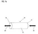
図1aは、本発明による第1の態様のインプラント10を示す。インプラント10は管状基体12から成り、その両側14及び16は開いており、その中を体液が流れることができる。インプラント10の基体12を通って流れる体液、特に血液の流れの方向は二つの矢印18,20により示されている。 FIG. 1a shows a first embodiment of an
図1bは、第2の態様の好適なインプラント30を示す。基体32は中空体として設計されているが、インプラント30が固定される脈管に輪郭を合わせていない。流れの方向は、再度矢印18,20により示され、基体は入り口と出口34,36を持っている。図1aに示された態様と異なり、体液は基体32の中又は周囲を通って内側と外側の両方を流れる。身体の中のインプラント32の相対位置を保証するために、固定部38が基体上に配置されており、その固定部は埋め込み後血管壁に支持され、その形状により確実に留まることを保証する。固定部38はこの特殊例ではジグザグデザインであるが、他の形状を取ることもできる。さらに、固定部38は、少なくともできうる限り、生分解性材料からなる。固定部38は、少なくとも活性物質の90重量%、好ましくは95重量%の放出期間中インプラント30の固定が保証されるように設計される。固定部の特別な設計は、なかんずく、埋め込み部位の流れの状態、活性成分の放出動態及び基体32の分解特性に依存するので、インプラント30は個別の応用に合わせてそれぞれ適合させなければならない。製造上の理由から、固定部38は好ましくは基体32と同じ生分解性材料から作られ、それと一体的に連結されている。 FIG. 1b shows a
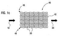
図1cは、本発明の第3の態様のインプラント40を図で示す。この態様では、基体42は閉鎖構造として設計されており、すなわち、埋め込み直後は基体の外壁のみが体液と接触する。示された基体42は、網状構造であり、固定部48によって脈管に固定されている。網の個々の糸の間に形成される隙間50は、活性物質を含有するフィルム様のマトリックスによって橋渡しされている(spanned)。このマトリックスは、例えば、網状の基体42をマトリックスを含有する溶液に漬け、次いで湿った基体42を乾燥することにより適用することができる。基体42、並びにマトリックスは生分解性マトリックスから形成されている。 FIG. 1c schematically illustrates an
図1a,1b及び1cにおける基体12,32,42は、体液中に放出される一つの、必要があれば複数の活性物質の基材(substrate)として寄与する。活性成分の放出中又は少なくともその後基体12,32,42は可及的に完全に分解する、すなわち、少なくとも可能な限りそれは生分解性材料からなる。 The
特に元素マグネシウム、鉄及びタングステンの合金は、基体12,32,42のための生分解性材料と考えられる。この場合に、述べた元素それぞれは、少なくとも60重量%、好ましくは70重量%超、特に好ましくは80重量%超の合金中の含有率を有する。特に好ましいのはマグネシウム合金であり、これは希土類金属及びイットリウムを含有し、通常タイプWEの合金と呼ばれている。この中で材料WEW43は特に適することが立証された、すなわち、活性物質の生分解性は制御された様式で起こり、分解中に放出される分解生成物は毒作用が無いかあっても少なく、そして活性物質を処理する場合に、マグネシウム合金の通常の工作技術を使用することができる。 In particular, the alloys of elemental magnesium, iron and tungsten are considered biodegradable materials for the
さらに、高い生体適合性が期待されるため、1及び30重量%のリチウムを含有するマグネシウム合金が好ましい。また、操作性、機械的及び分解性に関する特性故に、0.1〜10重量%のアルミニウムを含有するマグネシウム合金及び0.01〜2重量%のジルコニウムを含有するマグネシウム合金も好ましい。上記のマグネシウム合金の構成成分、つまり、希土類金属(E)、イットリウム(W)、リチウム(L)、アルミニウム(A)及びジルコニウム(K)−はいずれかの組み合わせで合金の部分を形成することができ、合金構成成分の標準化された略号はASTMにしたがってカッコ内に示されている。例えば、以下のタイプの合金組成を使用することができる:LWE,AL,LAE及びLE、この文字の配列は使用される合金組成にしたがって入れ替えることができる。 Furthermore, since high biocompatibility is expected, a magnesium alloy containing 1 and 30% by weight of lithium is preferable. Also preferred are magnesium alloys containing 0.1 to 10 wt% aluminum and magnesium alloys containing 0.01 to 2 wt% zirconium because of their operability, mechanical and degradability characteristics. The constituent components of the magnesium alloy, that is, the rare earth metal (E), yttrium (W), lithium (L), aluminum (A), and zirconium (K) — may form a part of the alloy in any combination. The standardized abbreviations for the alloy constituents are shown in parentheses according to ASTM. For example, the following types of alloy compositions can be used: LWE, AL, LAE and LE, the arrangement of this letter can be interchanged according to the alloy composition used.
インプラント10の基体12は、図1aには構造的にあまり詳細には示されていない。しかし、通常基体12は完全に隙間のないチューブとして存在するのではなく、むしろ多様な支柱又はワイヤー様の構造部品から成り立っている。そのような構造は、これにより埋め込みの部位へのインプラントの導入を非常に容易にするので、特に好ましい。したがって、構造部品が適切に設計されるならば、基体12は、最初は直径の小さい非拡大状態を取ることができ、そして埋め込みの部位において拡大した後、第2の拡大した状態になることができる。インプラント10の非拡大状態において、埋め込みの部位までのインプラントの導入はかなり容易になると考えられる。この目的のために、カテーテルシステムのバルーン上にインプラント10を取り付けるようにすることができる。次いで、類似のシステムにおける拡張ステントの場合と同様に、バルーンカテーテルを身体の中に導入し、そして目的の位置でバルーンを膨らませることによりインプラント10を拡大する。インプラント10を導入する目的のために、基体システム上に3分の1、収縮した状態にすることができることがインプラント10にとって有利である。さらに、機械的に引っ張る又は押す装置により、又は熱変形により作動する埋め込みシステムを使用することができる。例えば、局所的熱の影響により拡大する延長したニチノールワイヤーの3又は4を準備することができる。ニチノールワイヤーは、このワイヤーの拡大のために埋め込み部位にインプラントが固定させられるように、インプラントに対して配置される。したがって、この埋め込みシステムは上記固定部38、48を組み込んだインプラントに理想的に適している。 The
原理的には、図1aによる基体12を形成するインプラント10の構造部品の設計は、先行技術のステント設計に基づくことができる。しかし、インプラント10は支持機能を発揮する必要がないことを言明しなければならない、すなわち、ステントは血管損傷を防ぐために非常に柔らかい設計でなければならない。設計は脈管中に固定するのに役立ち、体液によってインプラント10が運ばれるのを防がなければならない。例えば血管壁と接触しているインプラント10上のいくつかの場所における表面変化又は抗増殖物質を有するコーティングの適用による、インプラント10の血管壁への伸展という事実により、活性物質の溶出が妨害されてはならない。 In principle, the design of the structural parts of the
図2aから2cは、その中で基体12,32,42が活性物質22の基材又は活性物質22を含有するマトリックスとして作用する領域における図1aから1cに示されたインプラント10,30,40の断面を極めて模式的に示す。簡潔に述べるために、参照は以下においては図1aに示されたインプラント10の種類についてのみ示される。しかし、示された寸法は、異なる形状の他のインプラントに困難なく変換することができる。 FIGS. 2a to 2c show the
図2aにおいて、活性物質22はコーティング24として基体12に適用される。論理的にコーティング24は管状基体12の内側にあるので、流れる体液は活性物質22と接触することができ、下位の組織領域の中へ溶解した形態で活性物質を溶出することができる。活性物質22は、基体12に、純粋な形態で例えば、微結晶又は無定形物として接着することができる。しかし、基体12へのより良い接着を促進するために及び/又は活性物質22の放出に影響するために、例えばマトリックスに埋め込まれた活性物質22も想定される。例えば、ヒアルロン酸及びその誘導体のような生分解性ポリマーはマトリックスとして考慮することができる。 In FIG. 2 a, the
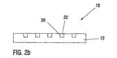
図2bに示された第2の態様では、インプラント10の基体12へ空所26が導入され、その中へ活性物質22又は活性物質22を含有するマトリックスが充填される。このような空所26は、例えば、先行技術のレーザー操作により作ることができる。空所26は割れ目、穴又はその他の幾何学的形状により達成できる。活性物質22は、例えば活性物質22を含有する溶液の中に浸し、溶液を乾燥し、空所26の外にある活性物質の堆積を吹き飛ばすことにより空所26の中に導入することができる。流れ去る体液のために活性物質22は空所26から徐々に流れ出る。同時に、この過程は基体12が徐々に分解することにより強制的に行われる。 In the second embodiment shown in FIG. 2 b, a cavity 26 is introduced into the
最後に、図2cに示された第3の態様のインプラント10では、基体12はその中に活性物質22が導入される中空の空間28を持っている。基体12の体液に接する側が分解するだけでなく、活性物質22は体液中へ溶出する。このようなシステムは、例えば、活性物質22の溶液が毛管現象によって導入された中空ワイヤーを使用することにより実現することができる。 Finally, in the
活性物質22の放出能力を制御するために、記述した寸法を変更できることはおのずから明白である。一つの活性物質のみならず、複数の活性物質を互いに相対的に時間をずらして放出することも考えられる。この場合に、一つの又は複数の活性物質の放出は、基材特質の選択、基体上の活性物質の幾何学的位置(すなわち、コーティング、くぼみ又は中空空間)、活性物質を含有する可能性のあるマトリックスの性質及び埋め込みの部位における流動学的及び解剖学的条件に依存する。上記の本発明のインプラントの種類は、理想的には局部薬物送達(RDD)の目的に適している。 It will be appreciated that the dimensions described can be varied in order to control the release capacity of the
Claims (13)
Translated fromJapanese脈管に面する側に、少なくとも一定の領域に、コーティング(24)及び/または
一つ又は複数のくぼみ(26)及び/または
一つ又は複数の中空体(28)、
を有し、
その中に活性物質(22)を含むことを特徴とする上記請求項のいずれか一つに記載のインプラント。The base (12, 32) is
On the side facing the vessel, in at least certain areas, the coating (24) and / or one or more indentations (26) and / or one or more hollow bodies (28),
Have
Implant according to any one of the preceding claims, characterized in that it contains an active substance (22).
Applications Claiming Priority (5)
| Application Number | Priority Date | Filing Date | Title |
|---|---|---|---|
| DE102004006745.7 | 2004-02-06 | ||
| DE102004006745 | 2004-02-06 | ||
| DE102004029611.1 | 2004-06-09 | ||
| DE102004029611ADE102004029611A1 (en) | 2004-02-06 | 2004-06-09 | Implant for e.g. releasing active substances into a vessel through which body fluids flow, comprises a base consisting of a biodegradable material as the carrier of the active substances |
| PCT/EP2005/001167WO2005075005A1 (en) | 2004-02-06 | 2005-02-04 | Implant for releasing an active substance into a vessel through which a body medium flows |
Publications (2)
| Publication Number | Publication Date |
|---|---|
| JP2007520292Atrue JP2007520292A (en) | 2007-07-26 |
| JP4769730B2 JP4769730B2 (en) | 2011-09-07 |
Family
ID=34801879
Family Applications (1)
| Application Number | Title | Priority Date | Filing Date |
|---|---|---|---|
| JP2006551814AExpired - Fee RelatedJP4769730B2 (en) | 2004-02-06 | 2005-02-04 | Implants for releasing active substances into the vascular fluid flow |
Country Status (4)
| Country | Link |
|---|---|
| US (1) | US9095642B2 (en) |
| JP (1) | JP4769730B2 (en) |
| CN (1) | CN1905913B (en) |
| DE (1) | DE102004029611A1 (en) |
Families Citing this family (262)
| Publication number | Priority date | Publication date | Assignee | Title |
|---|---|---|---|---|
| WO2003002243A2 (en) | 2001-06-27 | 2003-01-09 | Remon Medical Technologies Ltd. | Method and device for electrochemical formation of therapeutic species in vivo |
| US20070084897A1 (en) | 2003-05-20 | 2007-04-19 | Shelton Frederick E Iv | Articulating surgical stapling instrument incorporating a two-piece e-beam firing mechanism |
| US9060770B2 (en) | 2003-05-20 | 2015-06-23 | Ethicon Endo-Surgery, Inc. | Robotically-driven surgical instrument with E-beam driver |
| US11998198B2 (en) | 2004-07-28 | 2024-06-04 | Cilag Gmbh International | Surgical stapling instrument incorporating a two-piece E-beam firing mechanism |
| US9072535B2 (en) | 2011-05-27 | 2015-07-07 | Ethicon Endo-Surgery, Inc. | Surgical stapling instruments with rotatable staple deployment arrangements |
| US11890012B2 (en) | 2004-07-28 | 2024-02-06 | Cilag Gmbh International | Staple cartridge comprising cartridge body and attached support |
| US11246590B2 (en) | 2005-08-31 | 2022-02-15 | Cilag Gmbh International | Staple cartridge including staple drivers having different unfired heights |
| US7934630B2 (en) | 2005-08-31 | 2011-05-03 | Ethicon Endo-Surgery, Inc. | Staple cartridges for forming staples having differing formed staple heights |
| US11484312B2 (en) | 2005-08-31 | 2022-11-01 | Cilag Gmbh International | Staple cartridge comprising a staple driver arrangement |
| US7669746B2 (en) | 2005-08-31 | 2010-03-02 | Ethicon Endo-Surgery, Inc. | Staple cartridges for forming staples having differing formed staple heights |
| US10159482B2 (en) | 2005-08-31 | 2018-12-25 | Ethicon Llc | Fastener cartridge assembly comprising a fixed anvil and different staple heights |
| US20070106317A1 (en) | 2005-11-09 | 2007-05-10 | Shelton Frederick E Iv | Hydraulically and electrically actuated articulation joints for surgical instruments |
| DE102005059606A1 (en)* | 2005-12-12 | 2007-06-14 | Raumedic Ag | Active agent-application device for application in a gastro-intestinal tract, in a bladder or in uterus, comprises application mechanism with the agent, and a holding mechanism for the application mechanism |
| US8840660B2 (en) | 2006-01-05 | 2014-09-23 | Boston Scientific Scimed, Inc. | Bioerodible endoprostheses and methods of making the same |
| US20110295295A1 (en) | 2006-01-31 | 2011-12-01 | Ethicon Endo-Surgery, Inc. | Robotically-controlled surgical instrument having recording capabilities |
| US7845537B2 (en) | 2006-01-31 | 2010-12-07 | Ethicon Endo-Surgery, Inc. | Surgical instrument having recording capabilities |
| US11793518B2 (en) | 2006-01-31 | 2023-10-24 | Cilag Gmbh International | Powered surgical instruments with firing system lockout arrangements |
| US8820603B2 (en) | 2006-01-31 | 2014-09-02 | Ethicon Endo-Surgery, Inc. | Accessing data stored in a memory of a surgical instrument |
| US8708213B2 (en) | 2006-01-31 | 2014-04-29 | Ethicon Endo-Surgery, Inc. | Surgical instrument having a feedback system |
| US8186555B2 (en) | 2006-01-31 | 2012-05-29 | Ethicon Endo-Surgery, Inc. | Motor-driven surgical cutting and fastening instrument with mechanical closure system |
| US20120292367A1 (en) | 2006-01-31 | 2012-11-22 | Ethicon Endo-Surgery, Inc. | Robotically-controlled end effector |
| US8089029B2 (en) | 2006-02-01 | 2012-01-03 | Boston Scientific Scimed, Inc. | Bioabsorbable metal medical device and method of manufacture |
| US8992422B2 (en) | 2006-03-23 | 2015-03-31 | Ethicon Endo-Surgery, Inc. | Robotically-controlled endoscopic accessory channel |
| US8048150B2 (en) | 2006-04-12 | 2011-11-01 | Boston Scientific Scimed, Inc. | Endoprosthesis having a fiber meshwork disposed thereon |
| US20070258903A1 (en)* | 2006-05-02 | 2007-11-08 | Kleiner Lothar W | Methods, compositions and devices for treating lesioned sites using bioabsorbable carriers |
| EP2054537A2 (en) | 2006-08-02 | 2009-05-06 | Boston Scientific Scimed, Inc. | Endoprosthesis with three-dimensional disintegration control |
| DE102006038241A1 (en)* | 2006-08-07 | 2008-02-14 | Biotronik Vi Patent Ag | Stent with a genisteinhaltigen coating or Kavitätenfüllung |
| JP2010503489A (en) | 2006-09-15 | 2010-02-04 | ボストン サイエンティフィック リミテッド | Biodegradable endoprosthesis and method for producing the same |
| WO2008034066A1 (en) | 2006-09-15 | 2008-03-20 | Boston Scientific Limited | Bioerodible endoprostheses and methods of making the same |
| EP2959925B1 (en) | 2006-09-15 | 2018-08-29 | Boston Scientific Limited | Medical devices and methods of making the same |
| ES2357661T3 (en) | 2006-09-15 | 2011-04-28 | Boston Scientific Scimed, Inc. | BIOEROSIONABLE ENDOPROOTHESIS WITH BIOESTABLE INORGANIC LAYERS. |
| WO2008036548A2 (en) | 2006-09-18 | 2008-03-27 | Boston Scientific Limited | Endoprostheses |
| US10568652B2 (en) | 2006-09-29 | 2020-02-25 | Ethicon Llc | Surgical staples having attached drivers of different heights and stapling instruments for deploying the same |
| US11980366B2 (en) | 2006-10-03 | 2024-05-14 | Cilag Gmbh International | Surgical instrument |
| DE112007003309B4 (en)* | 2006-11-27 | 2013-02-07 | Berthold Nies | Bone implant and set for the production of bone implants and its use |
| ES2506144T3 (en) | 2006-12-28 | 2014-10-13 | Boston Scientific Limited | Bioerodible endoprosthesis and their manufacturing procedure |
| US8632535B2 (en) | 2007-01-10 | 2014-01-21 | Ethicon Endo-Surgery, Inc. | Interlock and surgical instrument including same |
| US8684253B2 (en) | 2007-01-10 | 2014-04-01 | Ethicon Endo-Surgery, Inc. | Surgical instrument with wireless communication between a control unit of a robotic system and remote sensor |
| US20220061862A1 (en)* | 2007-01-11 | 2022-03-03 | Cilag Gmbh International | Surgical stapling device with a curved end effector |
| US20080169333A1 (en) | 2007-01-11 | 2008-07-17 | Shelton Frederick E | Surgical stapler end effector with tapered distal end |
| DE102007004589A1 (en)* | 2007-01-30 | 2008-07-31 | Orlowski, Michael, Dr. | Reabsorbable implant stent for blood vessels, urinary passages, respiratory system, biliary tract or digestive tract, comprises magnesium alloy containing magnesium, calcium or yattrium |
| US8931682B2 (en) | 2007-06-04 | 2015-01-13 | Ethicon Endo-Surgery, Inc. | Robotically-controlled shaft based rotary drive systems for surgical instruments |
| US11564682B2 (en) | 2007-06-04 | 2023-01-31 | Cilag Gmbh International | Surgical stapler device |
| US7753245B2 (en) | 2007-06-22 | 2010-07-13 | Ethicon Endo-Surgery, Inc. | Surgical stapling instruments |
| US11849941B2 (en) | 2007-06-29 | 2023-12-26 | Cilag Gmbh International | Staple cartridge having staple cavities extending at a transverse angle relative to a longitudinal cartridge axis |
| US8052745B2 (en) | 2007-09-13 | 2011-11-08 | Boston Scientific Scimed, Inc. | Endoprosthesis |
| US8573465B2 (en) | 2008-02-14 | 2013-11-05 | Ethicon Endo-Surgery, Inc. | Robotically-controlled surgical end effector system with rotary actuated closure systems |
| JP5410110B2 (en) | 2008-02-14 | 2014-02-05 | エシコン・エンド−サージェリィ・インコーポレイテッド | Surgical cutting / fixing instrument with RF electrode |
| US7866527B2 (en) | 2008-02-14 | 2011-01-11 | Ethicon Endo-Surgery, Inc. | Surgical stapling apparatus with interlockable firing system |
| US8636736B2 (en) | 2008-02-14 | 2014-01-28 | Ethicon Endo-Surgery, Inc. | Motorized surgical cutting and fastening instrument |
| US11986183B2 (en) | 2008-02-14 | 2024-05-21 | Cilag Gmbh International | Surgical cutting and fastening instrument comprising a plurality of sensors to measure an electrical parameter |
| US9585657B2 (en) | 2008-02-15 | 2017-03-07 | Ethicon Endo-Surgery, Llc | Actuator for releasing a layer of material from a surgical end effector |
| DE102008019748A1 (en)* | 2008-04-18 | 2009-10-22 | Gottfried Wilhelm Leibniz Universität Hannover | Bioresorbable material |
| US7998192B2 (en) | 2008-05-09 | 2011-08-16 | Boston Scientific Scimed, Inc. | Endoprostheses |
| US8236046B2 (en) | 2008-06-10 | 2012-08-07 | Boston Scientific Scimed, Inc. | Bioerodible endoprosthesis |
| DE102008002395A1 (en)* | 2008-06-12 | 2009-12-17 | Biotronik Vi Patent Ag | Drug-loaded implant |
| US8202531B2 (en)* | 2008-07-23 | 2012-06-19 | Warsaw Orthopedic, Inc. | Drug depots having one or more anchoring members |
| US7985252B2 (en) | 2008-07-30 | 2011-07-26 | Boston Scientific Scimed, Inc. | Bioerodible endoprosthesis |
| US11648005B2 (en) | 2008-09-23 | 2023-05-16 | Cilag Gmbh International | Robotically-controlled motorized surgical instrument with an end effector |
| US9386983B2 (en) | 2008-09-23 | 2016-07-12 | Ethicon Endo-Surgery, Llc | Robotically-controlled motorized surgical instrument |
| US9005230B2 (en) | 2008-09-23 | 2015-04-14 | Ethicon Endo-Surgery, Inc. | Motorized surgical instrument |
| US8210411B2 (en) | 2008-09-23 | 2012-07-03 | Ethicon Endo-Surgery, Inc. | Motor-driven surgical cutting instrument |
| US8382824B2 (en) | 2008-10-03 | 2013-02-26 | Boston Scientific Scimed, Inc. | Medical implant having NANO-crystal grains with barrier layers of metal nitrides or fluorides |
| US8608045B2 (en) | 2008-10-10 | 2013-12-17 | Ethicon Endo-Sugery, Inc. | Powered surgical cutting and stapling apparatus with manually retractable firing system |
| EP2403546A2 (en) | 2009-03-02 | 2012-01-11 | Boston Scientific Scimed, Inc. | Self-buffering medical implants |
| US8435281B2 (en) | 2009-04-10 | 2013-05-07 | Boston Scientific Scimed, Inc. | Bioerodible, implantable medical devices incorporating supersaturated magnesium alloys |
| US8220688B2 (en) | 2009-12-24 | 2012-07-17 | Ethicon Endo-Surgery, Inc. | Motor-driven surgical cutting instrument with electric actuator directional control assembly |
| US8668732B2 (en) | 2010-03-23 | 2014-03-11 | Boston Scientific Scimed, Inc. | Surface treated bioerodible metal endoprostheses |
| US9629814B2 (en) | 2010-09-30 | 2017-04-25 | Ethicon Endo-Surgery, Llc | Tissue thickness compensator configured to redistribute compressive forces |
| US9016542B2 (en) | 2010-09-30 | 2015-04-28 | Ethicon Endo-Surgery, Inc. | Staple cartridge comprising compressible distortion resistant components |
| US11925354B2 (en) | 2010-09-30 | 2024-03-12 | Cilag Gmbh International | Staple cartridge comprising staples positioned within a compressible portion thereof |
| US12213666B2 (en) | 2010-09-30 | 2025-02-04 | Cilag Gmbh International | Tissue thickness compensator comprising layers |
| US11812965B2 (en) | 2010-09-30 | 2023-11-14 | Cilag Gmbh International | Layer of material for a surgical end effector |
| US9386988B2 (en) | 2010-09-30 | 2016-07-12 | Ethicon End-Surgery, LLC | Retainer assembly including a tissue thickness compensator |
| US10945731B2 (en) | 2010-09-30 | 2021-03-16 | Ethicon Llc | Tissue thickness compensator comprising controlled release and expansion |
| US9788834B2 (en) | 2010-09-30 | 2017-10-17 | Ethicon Llc | Layer comprising deployable attachment members |
| US8695866B2 (en) | 2010-10-01 | 2014-04-15 | Ethicon Endo-Surgery, Inc. | Surgical instrument having a power control circuit |
| AU2012250197B2 (en) | 2011-04-29 | 2017-08-10 | Ethicon Endo-Surgery, Inc. | Staple cartridge comprising staples positioned within a compressible portion thereof |
| US11207064B2 (en) | 2011-05-27 | 2021-12-28 | Cilag Gmbh International | Automated end effector component reloading system for use with a robotic system |
| MX358135B (en) | 2012-03-28 | 2018-08-06 | Ethicon Endo Surgery Inc | Tissue thickness compensator comprising a plurality of layers. |
| BR112014024098B1 (en) | 2012-03-28 | 2021-05-25 | Ethicon Endo-Surgery, Inc. | staple cartridge |
| US9101358B2 (en) | 2012-06-15 | 2015-08-11 | Ethicon Endo-Surgery, Inc. | Articulatable surgical instrument comprising a firing drive |
| US12383267B2 (en) | 2012-06-28 | 2025-08-12 | Cilag Gmbh International | Robotically powered surgical device with manually-actuatable reversing system |
| US9282974B2 (en) | 2012-06-28 | 2016-03-15 | Ethicon Endo-Surgery, Llc | Empty clip cartridge lockout |
| US9408606B2 (en) | 2012-06-28 | 2016-08-09 | Ethicon Endo-Surgery, Llc | Robotically powered surgical device with manually-actuatable reversing system |
| US9289256B2 (en) | 2012-06-28 | 2016-03-22 | Ethicon Endo-Surgery, Llc | Surgical end effectors having angled tissue-contacting surfaces |
| US20140001231A1 (en) | 2012-06-28 | 2014-01-02 | Ethicon Endo-Surgery, Inc. | Firing system lockout arrangements for surgical instruments |
| RU2672520C2 (en) | 2013-03-01 | 2018-11-15 | Этикон Эндо-Серджери, Инк. | Hingedly turnable surgical instruments with conducting ways for signal transfer |
| BR112015021082B1 (en) | 2013-03-01 | 2022-05-10 | Ethicon Endo-Surgery, Inc | surgical instrument |
| US9629629B2 (en) | 2013-03-14 | 2017-04-25 | Ethicon Endo-Surgey, LLC | Control systems for surgical instruments |
| BR112015026109B1 (en) | 2013-04-16 | 2022-02-22 | Ethicon Endo-Surgery, Inc | surgical instrument |
| US9775609B2 (en) | 2013-08-23 | 2017-10-03 | Ethicon Llc | Tamper proof circuit for surgical instrument battery pack |
| US10013049B2 (en) | 2014-03-26 | 2018-07-03 | Ethicon Llc | Power management through sleep options of segmented circuit and wake up control |
| US20150272580A1 (en) | 2014-03-26 | 2015-10-01 | Ethicon Endo-Surgery, Inc. | Verification of number of battery exchanges/procedure count |
| US12232723B2 (en) | 2014-03-26 | 2025-02-25 | Cilag Gmbh International | Systems and methods for controlling a segmented circuit |
| BR112016021943B1 (en) | 2014-03-26 | 2022-06-14 | Ethicon Endo-Surgery, Llc | SURGICAL INSTRUMENT FOR USE BY AN OPERATOR IN A SURGICAL PROCEDURE |
| US10327764B2 (en) | 2014-09-26 | 2019-06-25 | Ethicon Llc | Method for creating a flexible staple line |
| BR112016023825B1 (en) | 2014-04-16 | 2022-08-02 | Ethicon Endo-Surgery, Llc | STAPLE CARTRIDGE FOR USE WITH A SURGICAL STAPLER AND STAPLE CARTRIDGE FOR USE WITH A SURGICAL INSTRUMENT |
| US20150297225A1 (en) | 2014-04-16 | 2015-10-22 | Ethicon Endo-Surgery, Inc. | Fastener cartridges including extensions having different configurations |
| CN106456159B (en) | 2014-04-16 | 2019-03-08 | 伊西康内外科有限责任公司 | Fastener Cartridge Assembly and Nail Retainer Cover Arrangement |
| CN106456176B (en) | 2014-04-16 | 2019-06-28 | 伊西康内外科有限责任公司 | Fastener Cartridge Including Extensions With Different Configurations |
| CN104188741A (en)* | 2014-08-29 | 2014-12-10 | 东莞颠覆产品设计有限公司 | Degradable connector implanted in body |
| US11311294B2 (en) | 2014-09-05 | 2022-04-26 | Cilag Gmbh International | Powered medical device including measurement of closure state of jaws |
| US10135242B2 (en) | 2014-09-05 | 2018-11-20 | Ethicon Llc | Smart cartridge wake up operation and data retention |
| BR112017004361B1 (en) | 2014-09-05 | 2023-04-11 | Ethicon Llc | ELECTRONIC SYSTEM FOR A SURGICAL INSTRUMENT |
| US10105142B2 (en) | 2014-09-18 | 2018-10-23 | Ethicon Llc | Surgical stapler with plurality of cutting elements |
| US11523821B2 (en) | 2014-09-26 | 2022-12-13 | Cilag Gmbh International | Method for creating a flexible staple line |
| US9924944B2 (en) | 2014-10-16 | 2018-03-27 | Ethicon Llc | Staple cartridge comprising an adjunct material |
| US10517594B2 (en) | 2014-10-29 | 2019-12-31 | Ethicon Llc | Cartridge assemblies for surgical staplers |
| US11141153B2 (en) | 2014-10-29 | 2021-10-12 | Cilag Gmbh International | Staple cartridges comprising driver arrangements |
| US10736636B2 (en) | 2014-12-10 | 2020-08-11 | Ethicon Llc | Articulatable surgical instrument system |
| US9943309B2 (en) | 2014-12-18 | 2018-04-17 | Ethicon Llc | Surgical instruments with articulatable end effectors and movable firing beam support arrangements |
| US9987000B2 (en) | 2014-12-18 | 2018-06-05 | Ethicon Llc | Surgical instrument assembly comprising a flexible articulation system |
| MX389118B (en) | 2014-12-18 | 2025-03-20 | Ethicon Llc | SURGICAL INSTRUMENT WITH AN ANVIL THAT CAN BE SELECTIVELY MOVED ON A DISCRETE, NON-MOBILE AXIS RELATIVE TO A STAPLE CARTRIDGE. |
| US10085748B2 (en) | 2014-12-18 | 2018-10-02 | Ethicon Llc | Locking arrangements for detachable shaft assemblies with articulatable surgical end effectors |
| US11154301B2 (en) | 2015-02-27 | 2021-10-26 | Cilag Gmbh International | Modular stapling assembly |
| US10441279B2 (en) | 2015-03-06 | 2019-10-15 | Ethicon Llc | Multiple level thresholds to modify operation of powered surgical instruments |
| JP2020121162A (en) | 2015-03-06 | 2020-08-13 | エシコン エルエルシーEthicon LLC | Time dependent evaluation of sensor data to determine stability element, creep element and viscoelastic element of measurement |
| US10433844B2 (en) | 2015-03-31 | 2019-10-08 | Ethicon Llc | Surgical instrument with selectively disengageable threaded drive systems |
| US10105139B2 (en) | 2015-09-23 | 2018-10-23 | Ethicon Llc | Surgical stapler having downstream current-based motor control |
| US10299878B2 (en) | 2015-09-25 | 2019-05-28 | Ethicon Llc | Implantable adjunct systems for determining adjunct skew |
| US10478188B2 (en) | 2015-09-30 | 2019-11-19 | Ethicon Llc | Implantable layer comprising a constricted configuration |
| US11890015B2 (en) | 2015-09-30 | 2024-02-06 | Cilag Gmbh International | Compressible adjunct with crossing spacer fibers |
| US10433846B2 (en) | 2015-09-30 | 2019-10-08 | Ethicon Llc | Compressible adjunct with crossing spacer fibers |
| US10292704B2 (en) | 2015-12-30 | 2019-05-21 | Ethicon Llc | Mechanisms for compensating for battery pack failure in powered surgical instruments |
| US10265068B2 (en) | 2015-12-30 | 2019-04-23 | Ethicon Llc | Surgical instruments with separable motors and motor control circuits |
| US11213293B2 (en) | 2016-02-09 | 2022-01-04 | Cilag Gmbh International | Articulatable surgical instruments with single articulation link arrangements |
| BR112018016098B1 (en) | 2016-02-09 | 2023-02-23 | Ethicon Llc | SURGICAL INSTRUMENT |
| US10448948B2 (en) | 2016-02-12 | 2019-10-22 | Ethicon Llc | Mechanisms for compensating for drivetrain failure in powered surgical instruments |
| US10426467B2 (en) | 2016-04-15 | 2019-10-01 | Ethicon Llc | Surgical instrument with detection sensors |
| US10357247B2 (en) | 2016-04-15 | 2019-07-23 | Ethicon Llc | Surgical instrument with multiple program responses during a firing motion |
| US11607239B2 (en) | 2016-04-15 | 2023-03-21 | Cilag Gmbh International | Systems and methods for controlling a surgical stapling and cutting instrument |
| US10828028B2 (en) | 2016-04-15 | 2020-11-10 | Ethicon Llc | Surgical instrument with multiple program responses during a firing motion |
| US20170296173A1 (en) | 2016-04-18 | 2017-10-19 | Ethicon Endo-Surgery, Llc | Method for operating a surgical instrument |
| US10363037B2 (en) | 2016-04-18 | 2019-07-30 | Ethicon Llc | Surgical instrument system comprising a magnetic lockout |
| US10500000B2 (en) | 2016-08-16 | 2019-12-10 | Ethicon Llc | Surgical tool with manual control of end effector jaws |
| US10582928B2 (en) | 2016-12-21 | 2020-03-10 | Ethicon Llc | Articulation lock arrangements for locking an end effector in an articulated position in response to actuation of a jaw closure system |
| US10973516B2 (en) | 2016-12-21 | 2021-04-13 | Ethicon Llc | Surgical end effectors and adaptable firing members therefor |
| JP7010957B2 (en) | 2016-12-21 | 2022-01-26 | エシコン エルエルシー | Shaft assembly with lockout |
| MX2019007295A (en) | 2016-12-21 | 2019-10-15 | Ethicon Llc | Surgical instrument system comprising an end effector lockout and a firing assembly lockout. |
| US20180168615A1 (en) | 2016-12-21 | 2018-06-21 | Ethicon Endo-Surgery, Llc | Method of deforming staples from two different types of staple cartridges with the same surgical stapling instrument |
| US11090048B2 (en) | 2016-12-21 | 2021-08-17 | Cilag Gmbh International | Method for resetting a fuse of a surgical instrument shaft |
| US20180168625A1 (en) | 2016-12-21 | 2018-06-21 | Ethicon Endo-Surgery, Llc | Surgical stapling instruments with smart staple cartridges |
| JP7010956B2 (en) | 2016-12-21 | 2022-01-26 | エシコン エルエルシー | How to staple tissue |
| JP2020501815A (en) | 2016-12-21 | 2020-01-23 | エシコン エルエルシーEthicon LLC | Surgical stapling system |
| US10542982B2 (en) | 2016-12-21 | 2020-01-28 | Ethicon Llc | Shaft assembly comprising first and second articulation lockouts |
| US10813638B2 (en) | 2016-12-21 | 2020-10-27 | Ethicon Llc | Surgical end effectors with expandable tissue stop arrangements |
| US11653914B2 (en) | 2017-06-20 | 2023-05-23 | Cilag Gmbh International | Systems and methods for controlling motor velocity of a surgical stapling and cutting instrument according to articulation angle of end effector |
| US10779820B2 (en) | 2017-06-20 | 2020-09-22 | Ethicon Llc | Systems and methods for controlling motor speed according to user input for a surgical instrument |
| US10307170B2 (en) | 2017-06-20 | 2019-06-04 | Ethicon Llc | Method for closed loop control of motor velocity of a surgical stapling and cutting instrument |
| US11517325B2 (en) | 2017-06-20 | 2022-12-06 | Cilag Gmbh International | Closed loop feedback control of motor velocity of a surgical stapling and cutting instrument based on measured displacement distance traveled over a specified time interval |
| US10881399B2 (en) | 2017-06-20 | 2021-01-05 | Ethicon Llc | Techniques for adaptive control of motor velocity of a surgical stapling and cutting instrument |
| US10993716B2 (en) | 2017-06-27 | 2021-05-04 | Ethicon Llc | Surgical anvil arrangements |
| US11266405B2 (en) | 2017-06-27 | 2022-03-08 | Cilag Gmbh International | Surgical anvil manufacturing methods |
| EP3420947B1 (en) | 2017-06-28 | 2022-05-25 | Cilag GmbH International | Surgical instrument comprising selectively actuatable rotatable couplers |
| US11484310B2 (en) | 2017-06-28 | 2022-11-01 | Cilag Gmbh International | Surgical instrument comprising a shaft including a closure tube profile |
| USD906355S1 (en) | 2017-06-28 | 2020-12-29 | Ethicon Llc | Display screen or portion thereof with a graphical user interface for a surgical instrument |
| US10765427B2 (en) | 2017-06-28 | 2020-09-08 | Ethicon Llc | Method for articulating a surgical instrument |
| US10758232B2 (en) | 2017-06-28 | 2020-09-01 | Ethicon Llc | Surgical instrument with positive jaw opening features |
| US11564686B2 (en) | 2017-06-28 | 2023-01-31 | Cilag Gmbh International | Surgical shaft assemblies with flexible interfaces |
| US10932772B2 (en) | 2017-06-29 | 2021-03-02 | Ethicon Llc | Methods for closed loop velocity control for robotic surgical instrument |
| US11974742B2 (en) | 2017-08-03 | 2024-05-07 | Cilag Gmbh International | Surgical system comprising an articulation bailout |
| US11944300B2 (en) | 2017-08-03 | 2024-04-02 | Cilag Gmbh International | Method for operating a surgical system bailout |
| US11134944B2 (en) | 2017-10-30 | 2021-10-05 | Cilag Gmbh International | Surgical stapler knife motion controls |
| US10842490B2 (en) | 2017-10-31 | 2020-11-24 | Ethicon Llc | Cartridge body design with force reduction based on firing completion |
| US10779826B2 (en) | 2017-12-15 | 2020-09-22 | Ethicon Llc | Methods of operating surgical end effectors |
| US10835330B2 (en) | 2017-12-19 | 2020-11-17 | Ethicon Llc | Method for determining the position of a rotatable jaw of a surgical instrument attachment assembly |
| US12336705B2 (en) | 2017-12-21 | 2025-06-24 | Cilag Gmbh International | Continuous use self-propelled stapling instrument |
| US11179151B2 (en) | 2017-12-21 | 2021-11-23 | Cilag Gmbh International | Surgical instrument comprising a display |
| US11207065B2 (en) | 2018-08-20 | 2021-12-28 | Cilag Gmbh International | Method for fabricating surgical stapler anvils |
| US11291440B2 (en) | 2018-08-20 | 2022-04-05 | Cilag Gmbh International | Method for operating a powered articulatable surgical instrument |
| US20200054321A1 (en) | 2018-08-20 | 2020-02-20 | Ethicon Llc | Surgical instruments with progressive jaw closure arrangements |
| US11696761B2 (en) | 2019-03-25 | 2023-07-11 | Cilag Gmbh International | Firing drive arrangements for surgical systems |
| US20200345359A1 (en) | 2019-04-30 | 2020-11-05 | Ethicon Llc | Tissue stop for a surgical instrument |
| US11648009B2 (en) | 2019-04-30 | 2023-05-16 | Cilag Gmbh International | Rotatable jaw tip for a surgical instrument |
| US11903581B2 (en) | 2019-04-30 | 2024-02-20 | Cilag Gmbh International | Methods for stapling tissue using a surgical instrument |
| US11553971B2 (en) | 2019-06-28 | 2023-01-17 | Cilag Gmbh International | Surgical RFID assemblies for display and communication |
| US11523822B2 (en) | 2019-06-28 | 2022-12-13 | Cilag Gmbh International | Battery pack including a circuit interrupter |
| US11771419B2 (en) | 2019-06-28 | 2023-10-03 | Cilag Gmbh International | Packaging for a replaceable component of a surgical stapling system |
| US11627959B2 (en) | 2019-06-28 | 2023-04-18 | Cilag Gmbh International | Surgical instruments including manual and powered system lockouts |
| US12004740B2 (en) | 2019-06-28 | 2024-06-11 | Cilag Gmbh International | Surgical stapling system having an information decryption protocol |
| US11660163B2 (en) | 2019-06-28 | 2023-05-30 | Cilag Gmbh International | Surgical system with RFID tags for updating motor assembly parameters |
| US11638587B2 (en) | 2019-06-28 | 2023-05-02 | Cilag Gmbh International | RFID identification systems for surgical instruments |
| US11684434B2 (en) | 2019-06-28 | 2023-06-27 | Cilag Gmbh International | Surgical RFID assemblies for instrument operational setting control |
| US11241235B2 (en) | 2019-06-28 | 2022-02-08 | Cilag Gmbh International | Method of using multiple RFID chips with a surgical assembly |
| US11607219B2 (en) | 2019-12-19 | 2023-03-21 | Cilag Gmbh International | Staple cartridge comprising a detachable tissue cutting knife |
| US11504122B2 (en) | 2019-12-19 | 2022-11-22 | Cilag Gmbh International | Surgical instrument comprising a nested firing member |
| US11911032B2 (en) | 2019-12-19 | 2024-02-27 | Cilag Gmbh International | Staple cartridge comprising a seating cam |
| US11529137B2 (en) | 2019-12-19 | 2022-12-20 | Cilag Gmbh International | Staple cartridge comprising driver retention members |
| US11701111B2 (en) | 2019-12-19 | 2023-07-18 | Cilag Gmbh International | Method for operating a surgical stapling instrument |
| US11844520B2 (en) | 2019-12-19 | 2023-12-19 | Cilag Gmbh International | Staple cartridge comprising driver retention members |
| US11576672B2 (en) | 2019-12-19 | 2023-02-14 | Cilag Gmbh International | Surgical instrument comprising a closure system including a closure member and an opening member driven by a drive screw |
| US11529139B2 (en) | 2019-12-19 | 2022-12-20 | Cilag Gmbh International | Motor driven surgical instrument |
| US12035913B2 (en) | 2019-12-19 | 2024-07-16 | Cilag Gmbh International | Staple cartridge comprising a deployable knife |
| US11559304B2 (en) | 2019-12-19 | 2023-01-24 | Cilag Gmbh International | Surgical instrument comprising a rapid closure mechanism |
| USD974560S1 (en) | 2020-06-02 | 2023-01-03 | Cilag Gmbh International | Staple cartridge |
| USD975851S1 (en) | 2020-06-02 | 2023-01-17 | Cilag Gmbh International | Staple cartridge |
| USD975850S1 (en) | 2020-06-02 | 2023-01-17 | Cilag Gmbh International | Staple cartridge |
| USD976401S1 (en) | 2020-06-02 | 2023-01-24 | Cilag Gmbh International | Staple cartridge |
| US11871925B2 (en) | 2020-07-28 | 2024-01-16 | Cilag Gmbh International | Surgical instruments with dual spherical articulation joint arrangements |
| US11517390B2 (en) | 2020-10-29 | 2022-12-06 | Cilag Gmbh International | Surgical instrument comprising a limited travel switch |
| US11931025B2 (en) | 2020-10-29 | 2024-03-19 | Cilag Gmbh International | Surgical instrument comprising a releasable closure drive lock |
| US11717289B2 (en) | 2020-10-29 | 2023-08-08 | Cilag Gmbh International | Surgical instrument comprising an indicator which indicates that an articulation drive is actuatable |
| US11617577B2 (en) | 2020-10-29 | 2023-04-04 | Cilag Gmbh International | Surgical instrument comprising a sensor configured to sense whether an articulation drive of the surgical instrument is actuatable |
| US11896217B2 (en) | 2020-10-29 | 2024-02-13 | Cilag Gmbh International | Surgical instrument comprising an articulation lock |
| US11534259B2 (en) | 2020-10-29 | 2022-12-27 | Cilag Gmbh International | Surgical instrument comprising an articulation indicator |
| US11779330B2 (en) | 2020-10-29 | 2023-10-10 | Cilag Gmbh International | Surgical instrument comprising a jaw alignment system |
| USD1013170S1 (en) | 2020-10-29 | 2024-01-30 | Cilag Gmbh International | Surgical instrument assembly |
| US11452526B2 (en) | 2020-10-29 | 2022-09-27 | Cilag Gmbh International | Surgical instrument comprising a staged voltage regulation start-up system |
| US11844518B2 (en) | 2020-10-29 | 2023-12-19 | Cilag Gmbh International | Method for operating a surgical instrument |
| US12053175B2 (en) | 2020-10-29 | 2024-08-06 | Cilag Gmbh International | Surgical instrument comprising a stowed closure actuator stop |
| USD980425S1 (en) | 2020-10-29 | 2023-03-07 | Cilag Gmbh International | Surgical instrument assembly |
| US11849943B2 (en) | 2020-12-02 | 2023-12-26 | Cilag Gmbh International | Surgical instrument with cartridge release mechanisms |
| US11678882B2 (en) | 2020-12-02 | 2023-06-20 | Cilag Gmbh International | Surgical instruments with interactive features to remedy incidental sled movements |
| US11744581B2 (en) | 2020-12-02 | 2023-09-05 | Cilag Gmbh International | Powered surgical instruments with multi-phase tissue treatment |
| US11890010B2 (en) | 2020-12-02 | 2024-02-06 | Cllag GmbH International | Dual-sided reinforced reload for surgical instruments |
| US11653920B2 (en) | 2020-12-02 | 2023-05-23 | Cilag Gmbh International | Powered surgical instruments with communication interfaces through sterile barrier |
| US11627960B2 (en) | 2020-12-02 | 2023-04-18 | Cilag Gmbh International | Powered surgical instruments with smart reload with separately attachable exteriorly mounted wiring connections |
| US11737751B2 (en) | 2020-12-02 | 2023-08-29 | Cilag Gmbh International | Devices and methods of managing energy dissipated within sterile barriers of surgical instrument housings |
| US11653915B2 (en) | 2020-12-02 | 2023-05-23 | Cilag Gmbh International | Surgical instruments with sled location detection and adjustment features |
| US11944296B2 (en) | 2020-12-02 | 2024-04-02 | Cilag Gmbh International | Powered surgical instruments with external connectors |
| US11950777B2 (en) | 2021-02-26 | 2024-04-09 | Cilag Gmbh International | Staple cartridge comprising an information access control system |
| US11950779B2 (en) | 2021-02-26 | 2024-04-09 | Cilag Gmbh International | Method of powering and communicating with a staple cartridge |
| US11723657B2 (en) | 2021-02-26 | 2023-08-15 | Cilag Gmbh International | Adjustable communication based on available bandwidth and power capacity |
| US11793514B2 (en) | 2021-02-26 | 2023-10-24 | Cilag Gmbh International | Staple cartridge comprising sensor array which may be embedded in cartridge body |
| US11744583B2 (en) | 2021-02-26 | 2023-09-05 | Cilag Gmbh International | Distal communication array to tune frequency of RF systems |
| US12108951B2 (en) | 2021-02-26 | 2024-10-08 | Cilag Gmbh International | Staple cartridge comprising a sensing array and a temperature control system |
| US11925349B2 (en) | 2021-02-26 | 2024-03-12 | Cilag Gmbh International | Adjustment to transfer parameters to improve available power |
| US11980362B2 (en) | 2021-02-26 | 2024-05-14 | Cilag Gmbh International | Surgical instrument system comprising a power transfer coil |
| US11730473B2 (en) | 2021-02-26 | 2023-08-22 | Cilag Gmbh International | Monitoring of manufacturing life-cycle |
| US11696757B2 (en) | 2021-02-26 | 2023-07-11 | Cilag Gmbh International | Monitoring of internal systems to detect and track cartridge motion status |
| US11701113B2 (en) | 2021-02-26 | 2023-07-18 | Cilag Gmbh International | Stapling instrument comprising a separate power antenna and a data transfer antenna |
| US12324580B2 (en) | 2021-02-26 | 2025-06-10 | Cilag Gmbh International | Method of powering and communicating with a staple cartridge |
| US11751869B2 (en) | 2021-02-26 | 2023-09-12 | Cilag Gmbh International | Monitoring of multiple sensors over time to detect moving characteristics of tissue |
| US11812964B2 (en) | 2021-02-26 | 2023-11-14 | Cilag Gmbh International | Staple cartridge comprising a power management circuit |
| US11749877B2 (en) | 2021-02-26 | 2023-09-05 | Cilag Gmbh International | Stapling instrument comprising a signal antenna |
| US11723658B2 (en) | 2021-03-22 | 2023-08-15 | Cilag Gmbh International | Staple cartridge comprising a firing lockout |
| US11826012B2 (en) | 2021-03-22 | 2023-11-28 | Cilag Gmbh International | Stapling instrument comprising a pulsed motor-driven firing rack |
| US11826042B2 (en) | 2021-03-22 | 2023-11-28 | Cilag Gmbh International | Surgical instrument comprising a firing drive including a selectable leverage mechanism |
| US11806011B2 (en) | 2021-03-22 | 2023-11-07 | Cilag Gmbh International | Stapling instrument comprising tissue compression systems |
| US11717291B2 (en) | 2021-03-22 | 2023-08-08 | Cilag Gmbh International | Staple cartridge comprising staples configured to apply different tissue compression |
| US11737749B2 (en) | 2021-03-22 | 2023-08-29 | Cilag Gmbh International | Surgical stapling instrument comprising a retraction system |
| US11759202B2 (en) | 2021-03-22 | 2023-09-19 | Cilag Gmbh International | Staple cartridge comprising an implantable layer |
| US11849944B2 (en) | 2021-03-24 | 2023-12-26 | Cilag Gmbh International | Drivers for fastener cartridge assemblies having rotary drive screws |
| US11793516B2 (en) | 2021-03-24 | 2023-10-24 | Cilag Gmbh International | Surgical staple cartridge comprising longitudinal support beam |
| US11896218B2 (en) | 2021-03-24 | 2024-02-13 | Cilag Gmbh International | Method of using a powered stapling device |
| US11896219B2 (en) | 2021-03-24 | 2024-02-13 | Cilag Gmbh International | Mating features between drivers and underside of a cartridge deck |
| US11744603B2 (en) | 2021-03-24 | 2023-09-05 | Cilag Gmbh International | Multi-axis pivot joints for surgical instruments and methods for manufacturing same |
| US11832816B2 (en) | 2021-03-24 | 2023-12-05 | Cilag Gmbh International | Surgical stapling assembly comprising nonplanar staples and planar staples |
| US11786239B2 (en) | 2021-03-24 | 2023-10-17 | Cilag Gmbh International | Surgical instrument articulation joint arrangements comprising multiple moving linkage features |
| US11944336B2 (en) | 2021-03-24 | 2024-04-02 | Cilag Gmbh International | Joint arrangements for multi-planar alignment and support of operational drive shafts in articulatable surgical instruments |
| US11849945B2 (en) | 2021-03-24 | 2023-12-26 | Cilag Gmbh International | Rotary-driven surgical stapling assembly comprising eccentrically driven firing member |
| US11903582B2 (en) | 2021-03-24 | 2024-02-20 | Cilag Gmbh International | Leveraging surfaces for cartridge installation |
| US11786243B2 (en) | 2021-03-24 | 2023-10-17 | Cilag Gmbh International | Firing members having flexible portions for adapting to a load during a surgical firing stroke |
| US11857183B2 (en) | 2021-03-24 | 2024-01-02 | Cilag Gmbh International | Stapling assembly components having metal substrates and plastic bodies |
| US12102323B2 (en) | 2021-03-24 | 2024-10-01 | Cilag Gmbh International | Rotary-driven surgical stapling assembly comprising a floatable component |
| US20220354487A1 (en) | 2021-05-10 | 2022-11-10 | Cilag Gmbh International | Method for implementing a staple system |
| US11826047B2 (en) | 2021-05-28 | 2023-11-28 | Cilag Gmbh International | Stapling instrument comprising jaw mounts |
| US11980363B2 (en) | 2021-10-18 | 2024-05-14 | Cilag Gmbh International | Row-to-row staple array variations |
| US12432790B2 (en) | 2021-10-28 | 2025-09-30 | Cilag Gmbh International | Method and device for transmitting UART communications over a security short range wireless communication |
| US11937816B2 (en) | 2021-10-28 | 2024-03-26 | Cilag Gmbh International | Electrical lead arrangements for surgical instruments |
| US12089841B2 (en) | 2021-10-28 | 2024-09-17 | Cilag CmbH International | Staple cartridge identification systems |
Citations (3)
| Publication number | Priority date | Publication date | Assignee | Title |
|---|---|---|---|---|
| JP2001511049A (en)* | 1997-07-18 | 2001-08-07 | メイヤー,ヨルク | In vivo biodegradable metal implant |
| WO2003090818A2 (en)* | 2002-04-24 | 2003-11-06 | Sun Biomedical, Ltd. | Drug-delivery endovascular stent and method for treating restenosis |
| JP2004160236A (en)* | 2002-11-13 | 2004-06-10 | Biotronik Gmbh & Co Kg | Endoprosthesis |
Family Cites Families (15)
| Publication number | Priority date | Publication date | Assignee | Title |
|---|---|---|---|---|
| EP0604022A1 (en)* | 1992-12-22 | 1994-06-29 | Advanced Cardiovascular Systems, Inc. | Multilayered biodegradable stent and method for its manufacture |
| US5419760A (en) | 1993-01-08 | 1995-05-30 | Pdt Systems, Inc. | Medicament dispensing stent for prevention of restenosis of a blood vessel |
| CA2178541C (en)* | 1995-06-07 | 2009-11-24 | Neal E. Fearnot | Implantable medical device |
| US5843172A (en)* | 1997-04-15 | 1998-12-01 | Advanced Cardiovascular Systems, Inc. | Porous medicated stent |
| DE59913189D1 (en) | 1998-06-25 | 2006-05-04 | Biotronik Ag | Implantable, bioabsorbable vessel wall support, in particular coronary stent |
| DE19945049A1 (en)* | 1999-09-20 | 2001-03-22 | Meyer Joerg | Medicinal implant formed from alloy of tungsten, rhenium, osmium or molydenum having pH dependent corrosion rate, useful e.g. for controlled drug release |
| EP1420718A4 (en)* | 2000-09-29 | 2005-12-28 | Endovasc Ltd Inc | Resorbable prosthesis for medical treatment |
| US7083642B2 (en)* | 2000-12-22 | 2006-08-01 | Avantec Vascular Corporation | Delivery of therapeutic capable agents |
| US20050071016A1 (en)* | 2001-01-05 | 2005-03-31 | Gerd Hausdorf | Medical metal implants that can be decomposed by corrosion |
| NL1017672C2 (en)* | 2001-03-22 | 2002-09-24 | Hendrik Glastra | Implantable assembly with therapeutic effect. |
| DE10128100A1 (en) | 2001-06-11 | 2002-12-19 | Hannover Med Hochschule | Medical implant used for humans and animals is made from magnesium alloy containing additions of rare earth metals and lithium |
| US20030093147A1 (en) | 2001-11-13 | 2003-05-15 | Ogle Matthew F. | Medical devices that stimulate growth factor production |
| DE10163106A1 (en)* | 2001-12-24 | 2003-07-10 | Univ Hannover | Medical implants, prostheses, prosthesis parts, medical instruments, devices and aids made of a halide-modified magnesium material |
| DE10237571A1 (en) | 2002-08-13 | 2004-02-26 | Biotronik Meß- und Therapiegeräte GmbH & Co. Ingenieurbüro Berlin | Endovascular implant with active coating |
| US20050027350A1 (en)* | 2003-07-30 | 2005-02-03 | Biotronik Mess-Und Therapiegeraete Gmbh & Co Ingenieurbuero Berlin | Endovascular implant for the injection of an active substance into the media of a blood vessel |
- 2004
- 2004-06-09DEDE102004029611Apatent/DE102004029611A1/ennot_activeWithdrawn
- 2005
- 2005-02-04USUS10/597,099patent/US9095642B2/ennot_activeExpired - Fee Related
- 2005-02-04JPJP2006551814Apatent/JP4769730B2/ennot_activeExpired - Fee Related
- 2005-02-04CNCN200580001686.5Apatent/CN1905913B/ennot_activeExpired - Fee Related
Patent Citations (4)
| Publication number | Priority date | Publication date | Assignee | Title |
|---|---|---|---|---|
| JP2001511049A (en)* | 1997-07-18 | 2001-08-07 | メイヤー,ヨルク | In vivo biodegradable metal implant |
| WO2003090818A2 (en)* | 2002-04-24 | 2003-11-06 | Sun Biomedical, Ltd. | Drug-delivery endovascular stent and method for treating restenosis |
| JP2005523119A (en)* | 2002-04-24 | 2005-08-04 | サン バイオメディカル, リミテッド | Drug delivery intravascular stent and method for treating restenosis |
| JP2004160236A (en)* | 2002-11-13 | 2004-06-10 | Biotronik Gmbh & Co Kg | Endoprosthesis |
Also Published As
| Publication number | Publication date |
|---|---|
| CN1905913A (en) | 2007-01-31 |
| JP4769730B2 (en) | 2011-09-07 |
| CN1905913B (en) | 2010-10-06 |
| US9095642B2 (en) | 2015-08-04 |
| DE102004029611A1 (en) | 2005-08-25 |
| US20090182290A1 (en) | 2009-07-16 |
Similar Documents
| Publication | Publication Date | Title |
|---|---|---|
| JP4769730B2 (en) | Implants for releasing active substances into the vascular fluid flow | |
| EP1765220B1 (en) | Implantable device for drug delivery and improved visibility | |
| US20240188983A1 (en) | Coated endovascular intrasaccular occlusion device | |
| US7396538B2 (en) | Apparatus and method for delivery of mitomycin through an eluting biocompatible implantable medical device | |
| US6419692B1 (en) | Surface protection method for stents and balloon catheters for drug delivery | |
| US5342348A (en) | Method and device for treating and enlarging body lumens | |
| JP5536637B2 (en) | Intravascular device with net system | |
| US8052744B2 (en) | Medical devices and methods of making the same | |
| US20050147644A1 (en) | Reduced restenosis drug containing stents | |
| US6340368B1 (en) | Implantable device with radiopaque ends | |
| CA2520446A1 (en) | Therapeutic agent delivery device with controlled therapeutic agent release rates | |
| JP2011516132A (en) | Swellable biocompatible coating containing a bioactive substance | |
| CN101790391A (en) | Drug eluting medical device and method | |
| JP5461202B2 (en) | Bioabsorbable coating for medical devices | |
| CN112263360A (en) | In vivo drug eluting stent and preparation method thereof | |
| CA2552405C (en) | Implant for releasing an active substance into a vessel through which a body medium flows | |
| CN102939060B (en) | Vascular stent with double-coated structure | |
| US20210307761A1 (en) | Coated Endovascular Intrasaccular Occlusion Device Method of Use |
Legal Events
| Date | Code | Title | Description |
|---|---|---|---|
| A621 | Written request for application examination | Free format text:JAPANESE INTERMEDIATE CODE: A621 Effective date:20070814 | |
| A977 | Report on retrieval | Free format text:JAPANESE INTERMEDIATE CODE: A971007 Effective date:20100309 | |
| A131 | Notification of reasons for refusal | Free format text:JAPANESE INTERMEDIATE CODE: A131 Effective date:20100312 | |
| A521 | Request for written amendment filed | Free format text:JAPANESE INTERMEDIATE CODE: A523 Effective date:20100611 | |
| A131 | Notification of reasons for refusal | Free format text:JAPANESE INTERMEDIATE CODE: A131 Effective date:20101105 | |
| A521 | Request for written amendment filed | Free format text:JAPANESE INTERMEDIATE CODE: A523 Effective date:20110201 | |
| TRDD | Decision of grant or rejection written | ||
| A01 | Written decision to grant a patent or to grant a registration (utility model) | Free format text:JAPANESE INTERMEDIATE CODE: A01 Effective date:20110610 | |
| A01 | Written decision to grant a patent or to grant a registration (utility model) | Free format text:JAPANESE INTERMEDIATE CODE: A01 | |
| A61 | First payment of annual fees (during grant procedure) | Free format text:JAPANESE INTERMEDIATE CODE: A61 Effective date:20110620 | |
| R150 | Certificate of patent or registration of utility model | Ref document number:4769730 Country of ref document:JP Free format text:JAPANESE INTERMEDIATE CODE: R150 Free format text:JAPANESE INTERMEDIATE CODE: R150 | |
| FPAY | Renewal fee payment (event date is renewal date of database) | Free format text:PAYMENT UNTIL: 20140624 Year of fee payment:3 | |
| R250 | Receipt of annual fees | Free format text:JAPANESE INTERMEDIATE CODE: R250 | |
| R250 | Receipt of annual fees | Free format text:JAPANESE INTERMEDIATE CODE: R250 | |
| R250 | Receipt of annual fees | Free format text:JAPANESE INTERMEDIATE CODE: R250 | |
| R250 | Receipt of annual fees | Free format text:JAPANESE INTERMEDIATE CODE: R250 | |
| R250 | Receipt of annual fees | Free format text:JAPANESE INTERMEDIATE CODE: R250 | |
| S111 | Request for change of ownership or part of ownership | Free format text:JAPANESE INTERMEDIATE CODE: R313113 | |
| R350 | Written notification of registration of transfer | Free format text:JAPANESE INTERMEDIATE CODE: R350 | |
| R250 | Receipt of annual fees | Free format text:JAPANESE INTERMEDIATE CODE: R250 | |
| LAPS | Cancellation because of no payment of annual fees |