JP2007520285A - Method and apparatus for treating mammalian tissue - Google Patents
Method and apparatus for treating mammalian tissueDownload PDFInfo
- Publication number
- JP2007520285A JP2007520285AJP2006551698AJP2006551698AJP2007520285AJP 2007520285 AJP2007520285 AJP 2007520285AJP 2006551698 AJP2006551698 AJP 2006551698AJP 2006551698 AJP2006551698 AJP 2006551698AJP 2007520285 AJP2007520285 AJP 2007520285A
- Authority
- JP
- Japan
- Prior art keywords
- light
- light source
- target
- tissue
- head
- Prior art date
- Legal status (The legal status is an assumption and is not a legal conclusion. Google has not performed a legal analysis and makes no representation as to the accuracy of the status listed.)
- Pending
Links
Images


Classifications
- A—HUMAN NECESSITIES
- A61—MEDICAL OR VETERINARY SCIENCE; HYGIENE
- A61N—ELECTROTHERAPY; MAGNETOTHERAPY; RADIATION THERAPY; ULTRASOUND THERAPY
- A61N5/00—Radiation therapy
- A61N5/06—Radiation therapy using light
- A61N5/0613—Apparatus adapted for a specific treatment
- A61N5/0616—Skin treatment other than tanning
- A—HUMAN NECESSITIES
- A61—MEDICAL OR VETERINARY SCIENCE; HYGIENE
- A61B—DIAGNOSIS; SURGERY; IDENTIFICATION
- A61B18/00—Surgical instruments, devices or methods for transferring non-mechanical forms of energy to or from the body
- A61B18/18—Surgical instruments, devices or methods for transferring non-mechanical forms of energy to or from the body by applying electromagnetic radiation, e.g. microwaves
- A61B18/20—Surgical instruments, devices or methods for transferring non-mechanical forms of energy to or from the body by applying electromagnetic radiation, e.g. microwaves using laser
- A61B18/203—Surgical instruments, devices or methods for transferring non-mechanical forms of energy to or from the body by applying electromagnetic radiation, e.g. microwaves using laser applying laser energy to the outside of the body
- A—HUMAN NECESSITIES
- A61—MEDICAL OR VETERINARY SCIENCE; HYGIENE
- A61N—ELECTROTHERAPY; MAGNETOTHERAPY; RADIATION THERAPY; ULTRASOUND THERAPY
- A61N5/00—Radiation therapy
- A61N5/06—Radiation therapy using light
- A61N5/0613—Apparatus adapted for a specific treatment
- A61N5/062—Photodynamic therapy, i.e. excitation of an agent
- A—HUMAN NECESSITIES
- A61—MEDICAL OR VETERINARY SCIENCE; HYGIENE
- A61B—DIAGNOSIS; SURGERY; IDENTIFICATION
- A61B18/00—Surgical instruments, devices or methods for transferring non-mechanical forms of energy to or from the body
- A61B2018/00315—Surgical instruments, devices or methods for transferring non-mechanical forms of energy to or from the body for treatment of particular body parts
- A61B2018/00452—Skin
- A—HUMAN NECESSITIES
- A61—MEDICAL OR VETERINARY SCIENCE; HYGIENE
- A61N—ELECTROTHERAPY; MAGNETOTHERAPY; RADIATION THERAPY; ULTRASOUND THERAPY
- A61N5/00—Radiation therapy
- A61N5/06—Radiation therapy using light
- A61N2005/0635—Radiation therapy using light characterised by the body area to be irradiated
- A61N2005/0642—Irradiating part of the body at a certain distance
- A—HUMAN NECESSITIES
- A61—MEDICAL OR VETERINARY SCIENCE; HYGIENE
- A61N—ELECTROTHERAPY; MAGNETOTHERAPY; RADIATION THERAPY; ULTRASOUND THERAPY
- A61N5/00—Radiation therapy
- A61N5/06—Radiation therapy using light
- A61N2005/0635—Radiation therapy using light characterised by the body area to be irradiated
- A61N2005/0643—Applicators, probes irradiating specific body areas in close proximity
- A—HUMAN NECESSITIES
- A61—MEDICAL OR VETERINARY SCIENCE; HYGIENE
- A61N—ELECTROTHERAPY; MAGNETOTHERAPY; RADIATION THERAPY; ULTRASOUND THERAPY
- A61N5/00—Radiation therapy
- A61N5/06—Radiation therapy using light
- A61N2005/065—Light sources therefor
- A61N2005/0651—Diodes
- A61N2005/0652—Arrays of diodes
Landscapes
- Health & Medical Sciences (AREA)
- Life Sciences & Earth Sciences (AREA)
- Engineering & Computer Science (AREA)
- Biomedical Technology (AREA)
- Public Health (AREA)
- Physics & Mathematics (AREA)
- Nuclear Medicine, Radiotherapy & Molecular Imaging (AREA)
- Veterinary Medicine (AREA)
- Animal Behavior & Ethology (AREA)
- General Health & Medical Sciences (AREA)
- Pathology (AREA)
- Radiology & Medical Imaging (AREA)
- Biophysics (AREA)
- Optics & Photonics (AREA)
- Surgery (AREA)
- Electromagnetism (AREA)
- Otolaryngology (AREA)
- Heart & Thoracic Surgery (AREA)
- Medical Informatics (AREA)
- Molecular Biology (AREA)
- Radiation-Therapy Devices (AREA)
- Laser Surgery Devices (AREA)
Abstract
Translated fromJapaneseDescription
Translated fromJapanese本発明は、生体組織の治療、例えば、皮膚の皮膚科学的治療分野に関し、特に、哺乳類組織の治療法及び装置に関する。 The present invention relates to the treatment of living tissue, for example, the dermatological treatment of skin, and more particularly to a method and apparatus for treating mammalian tissue.
高齢化による人口動態推移と共に、一般には皮膚科学的治療、特に、加齢作用を遅らせるための皮膚科学的治療が次第にもてはやされるようになっている。 Along with demographic changes due to aging, dermatological treatments, particularly dermatological treatments for delaying the aging effect, are increasingly being promoted.
皮膚の加齢は、コラーゲン生産と分解のバランスを偏らせ、これが、小皺、顔面のたるみ、及び肌荒れをもたらすことが知られている。皮膚細胞を刺激してコラーゲン生産を促すことによってこの過程を部分的に逆転させることが可能である。老齢皮膚のコラーゲン合成を促進することによって小皺が減り、肌の肌理が改善されることが示されている。ある個人自身によるコラーゲンの生産を促進することの利点は、コラーゲンが順序正しい構造的なやり方で蓄積すること、及び、アレルギー、免疫反応、又は注射による感染の危険がないことである。 Skin aging is known to bias the balance between collagen production and degradation, which leads to wrinkles, facial sagging, and rough skin. This process can be partially reversed by stimulating skin cells to promote collagen production. It has been shown that promoting collagen synthesis in aged skin reduces wrinkles and improves skin texture. The advantage of facilitating the production of collagen by one individual is that the collagen accumulates in an ordered and structured manner and that there is no risk of allergies, immune reactions, or infection by injection.
加齢の皮膚に及ぼす作用を低減させるための従来技術がいくつかあるが、それらは、皮膚を熱的に傷つけるもので、それに伴った欠点もある。低レベルレーザー放射療法及び光活性化と呼ばれる、別の対処法が世に出た最初の時期は1960年代及び1970年代であった。当時、利用されていたいくつかのレーザーについて生物学的作用が試験された。当時の観察はほとんどが散発的なものであった。 There are several conventional techniques for reducing the effects on aging skin, but they are thermally damaging to the skin and have disadvantages associated therewith. The first time another treatment, called low-level laser radiation therapy and photoactivation, came into the world was in the 1960s and 1970s. Biological effects were tested on several lasers that were in use at the time. Most of the observations at that time were sporadic.
第2期は1980年代に始まった。この期間、プラシーボ効果と有意な結果を区別するために適切なコントロールが用いられた。人々はレーザー放射の波長に興味を有し、レーザー放射の治療的使用における光生物学的基盤を研究し始めた。 The second period began in the 1980s. During this period, appropriate controls were used to distinguish between placebo effects and significant results. People were interested in the wavelength of laser radiation and began to study the photobiological basis in the therapeutic use of laser radiation.
第3期は近年始まったばかりである。既存の光治療の光生物学的基盤に関しては更に多くのデータが利用可能となり、酵素及び膜の光活性化については更に多くのことが知られている。従来技術において光誘発法及び装置がいくつか提案されている。しかしながら、これまでのところ、それらは比較的不満足な結果しか生み出していない。 The third period has just begun in recent years. More data is available on the photobiological basis of existing phototherapy, and much more is known about photoactivation of enzymes and membranes. Several light induction methods and devices have been proposed in the prior art. However, so far they have produced relatively unsatisfactory results.
上記に鑑みれば、哺乳類組織治療のための新規の方法及び装置を供給する産業に対しては需要がある。 In view of the above, there is a need for industries that supply new methods and devices for mammalian tissue treatment.
本明細書の記述は多数の文書を参照し、これらの内容を参照することによりその全体を本明細書に含める。 The description herein refers to numerous documents and is hereby incorporated by reference in their entirety.
広い面において、本発明は、哺乳類組織において所定の生理的変化をもたらすための方法を提供する。方法は、組織の中に、活性化閾値電力密度よりも実質的に大きい電力密度をもたらす放射を組織に照射するが、その際、所定の生理的変化をもたらすのに好適な条件下で照射することを含む。 In a broad aspect, the present invention provides a method for effecting a predetermined physiological change in mammalian tissue. The method irradiates the tissue with radiation that results in a power density substantially greater than an activation threshold power density, under conditions suitable to effect a predetermined physiological change. Including that.
好都合なことに、請求される本発明は比較的実行が簡単で比較的安全である。請求される本発明は更に、生体に実行した場合比較的無痛で、比較的少数の治療で比較的著明な結果をもたらす。 Advantageously, the claimed invention is relatively simple to implement and relatively safe. The claimed invention is further relatively painless when performed on a living body and produces relatively significant results with a relatively small number of treatments.
本発明は、生理的過程を強化するのに比較的好適であり、比較的僅かな副作用しか引き起こさない。 The present invention is relatively suitable for enhancing physiological processes and causes relatively few side effects.
もう一つの広い面では、本発明は、哺乳類皮膚組織の治療法において、複数の放射パルスを含むパルス列を定める放射によって組織を照射する治療法で、
a.照射は、約400ナノメートルから約1500ナノメートルの波長を有し、
b.パルスはそれぞれ約1フェムト秒から約1時間の持続を有し、
c.パルスは互いに、約1マイクロ秒から約10秒のパルス間隔で隔てられ、かつ、
d.組織における各パルスの電力密度は、約0.1 mW/cm2から約10 W/cm2である、
ことを特徴とする治療法を提供する。In another broad aspect, the present invention relates to a method of irradiating tissue with radiation defining a pulse train comprising a plurality of radiation pulses in a method of treating mammalian skin tissue,
a. The irradiation has a wavelength of about 400 nanometers to about 1500 nanometers;
b. Each pulse has a duration of about 1 femtosecond to about 1 hour,
c. The pulses are separated from each other by a pulse interval of about 1 microsecond to about 10 seconds; and
d. The power density of each pulse in the tissue is about 0.1 mW / cm2 to about 10 W / cm2,
A therapeutic method characterized by the above is provided.
更に別の広い面において、本発明は、哺乳類組織の生理を変える方法において、複数のパルス列において、ここに、各パルス列は、所定のパルス持続時間を有する複数の放射パルスを含み、複数のパルスは互いにパルス間隔によって隔てられ、複数のパルス列は互いにパルス列間隔によって隔てられ、パルス列間隔はパルス間隔よりも実質的に長いことを特徴とする、前記複数のパルス列を定義する放射で組織を照射することを含む方法を提供する。 In yet another broad aspect, the present invention provides a method for altering the physiology of mammalian tissue, in a plurality of pulse trains, wherein each pulse train comprises a plurality of radiation pulses having a predetermined pulse duration, the plurality of pulses being Irradiating tissue with radiation defining the plurality of pulse trains, wherein the plurality of pulse trains are separated from each other by a pulse train interval, and the pulse train interval is substantially longer than the pulse train interval. A method of including is provided.
更に別の広い面では、本発明は、哺乳類組織の生理を変える方法において、分子のカスケード事象を活性化し、かつ、組織に含まれる細胞を活性化するのに好適な電力密度時間プロフィールに従って時間変動する放射によって組織を照射することを含む方法を提供する。 In yet another broad aspect, the present invention is a method for altering the physiology of mammalian tissue, in accordance with a power density time profile suitable for activating molecular cascade events and activating cells contained in the tissue. A method is provided that includes irradiating tissue with radiating radiation.
更に別の広い面では、本発明は、哺乳類組織において細胞外基質を再生する方法において、細胞外基質を再生させるのに好適な条件下で組織に放射を照射することを含む方法を提供する。 In yet another broad aspect, the present invention provides a method for regenerating extracellular matrix in mammalian tissue comprising irradiating the tissue under conditions suitable for regenerating the extracellular matrix.
更に別の広い面では、本発明は、哺乳類組織における組織の統合性を改善する方法において、哺乳類組織の組織統合性を改善するのに好適な条件下で組織に放射を照射することを含む方法を提供する。 In yet another broad aspect, the present invention provides a method for improving tissue integrity in mammalian tissue, comprising irradiating the tissue under conditions suitable for improving tissue integrity in mammalian tissue. I will provide a.
更に別の広い面では、本発明は、哺乳動物の皮膚組織に対して以前にもたらされた傷害を緩和するための方法において、ある電力密度時間プロフィールを示す放射で組織を照射し、それによって、放射が、組織内に、少なくとも所定の時間間隔だけ活性化閾値を上回る電力密度を有することが可能とされ、ここに、所定の時間間隔は、組織の温度が、それを上回ると、放射が、哺乳動物の皮膚組織に以前にもたらされた前記傷害に対して無効になってしまう過加熱温度を下回るように選ばれることを特徴とする前記放射で組織を照射することを含む方法を提供する。 In yet another broad aspect, the present invention provides a method for mitigating damage previously caused to mammalian skin tissue by irradiating the tissue with radiation that exhibits a certain power density time profile, thereby , The radiation can have a power density in the tissue that exceeds an activation threshold for at least a predetermined time interval, wherein the predetermined time interval indicates that when the tissue temperature exceeds, the radiation Providing a method comprising irradiating the tissue with the radiation, wherein the radiation is selected to be below an overheating temperature that would be ineffective against the injury previously caused to mammalian skin tissue To do.
このような傷害の例としては、加齢及び病態によってもたらされる傷害、例えば、湿疹、乾癬、及びその他多くのものが挙げられる。 Examples of such injuries include injuries caused by aging and pathological conditions such as eczema, psoriasis, and many others.
本発明によれば、標的表面に対し、所定の1組の光活性化光パラメータを有する光活性化光ビームを向けることによって標的生物活性の生理を変調させる光活性化装置において、光活性化光ビームを発射する光活性化光源;標的表面に対して光活性化光源の選択的位置づけを可能とする、光活性化光源に動作するように結合する位置決め手段;標的表面に対する光活性化光源の位置を評価するための位置評価手段を具える光活性化装置を提供する。 According to the present invention, in a photoactivation device that modulates the physiology of a target biological activity by directing a photoactivated light beam having a predetermined set of photoactivated light parameters to a target surface, A light-activated light source that emits a beam; positioning means operatively coupled to the light-activated light source that enables selective positioning of the light-activated light source relative to the target surface; There is provided a light activation device comprising a position evaluation means for evaluating the position.
本発明によれば、標的とする人体の治療領域に対し、所定の1組の光活性化光パラメータを有する光活性化光を向けることによって標的細胞活性の生理を変調させる光活性化装置において、光活性化光を発射する光活性化光源を含む治療ヘッドを含み、治療ヘッドは更に治療領域を冷却するための治療領域冷却手段を含むことを特徴とする、光活性化装置を更に提供する。 According to the present invention, in a photoactivation device that modulates the physiology of target cell activity by directing photoactivation light having a predetermined set of photoactivation light parameters to a target treatment area of a human body, There is further provided a light activation device comprising a treatment head including a light activated light source for emitting light activated light, the treatment head further comprising treatment region cooling means for cooling the treatment region.
典型的には、治療ヘッドは、治療領域とは、治療ヘッド−治療領域空間によって隔てられており、治療領域冷却手段は、治療領域を冷却するために、治療ヘッド−治療領域空間中を少なくとも部分的に流れる治療領域気流を造り出すための冷却気流手段を含む。治療ヘッドはまた、光活性化光源を冷却するための光源冷却手段を含んでいると好都合である。 Typically, the treatment head is separated from the treatment region by a treatment head-treatment region space, and the treatment region cooling means is at least partially in the treatment head-treatment region space to cool the treatment region. Cooling airflow means for creating a flowing therapeutic region airflow. The treatment head also advantageously includes light source cooling means for cooling the light activated light source.
本発明によれば、光活性化装置を用いて哺乳類組織を光活性化する方法において、光活性化装置は、所定の1組の光パラメータを有する光活性化ビームを生成するように適応した光活性化光源を含み、哺乳類組織は、光活性化ビームによって照射されるように適応した標的表面を定義し、方法は、光活性化光源と哺乳類組織を互いに、光活性化光源と哺乳類組織とが互いに所定の操作距離だけ隔てられるように位置づけること、及び、光活性化光源が標的表面から前記操作距離だけ隔てられている際に、標的表面に光活性化光を照射することを含み、操作距離は、光活性化光が生物組織を光活性化するように選ばれることを特徴とする方法が更に提供される。典型的には、方法は、光活性化光源と標的面の間の距離を、操作距離に向けて調節するための距離プローブを用いることを含む。 According to the present invention, in a method of photoactivating mammalian tissue using a photoactivation device, the photoactivation device is adapted to generate a light activation beam having a predetermined set of light parameters. A mammalian tissue defining a target surface adapted to be illuminated by a light-activated beam; and a method comprising: a light-activated light source and a mammalian tissue; Positioning at a predetermined operation distance from each other, and irradiating the target surface with photoactivation light when the photoactivation light source is separated from the target surface by the operation distance, Further provided is a method characterized in that the photoactivated light is selected to photoactivate biological tissue. Typically, the method includes using a distance probe to adjust the distance between the light activated light source and the target surface toward the operating distance.
都合の良いことに、この方法は、光活性化光源と標的面の間の距離を操作距離に向けて調節するための距離プローブの使用前に、光活性化光源を標的表面に向けて照準するために、光活性化光源に動作するように結合する照準装置から発する、照準光ビームを使用することを更に含む。 Conveniently, this method aims the light-activated light source towards the target surface prior to use of a distance probe to adjust the distance between the light-activated light source and the target surface towards the operating distance. For this purpose, the method further includes using an aiming light beam emanating from an aiming device operatively coupled to the light activated light source.
本発明によれば、光活性化装置を用いて哺乳類組織を光活性化する方法において、光活性化装置は、所定の1組の光パラメータを有する光活性化ビームを生成するように適応した光活性化光源を含み、哺乳類組織は、光活性化ビームによって照射されるように適応した標的表面を定義し、方法は、光活性化光源から発せられる光活性化光によって標的表面を照射すること、標的表面を所定の熱閾値を下回る温度に維持するように標的表面を冷却することを含むことを特徴とする方法が更に提供される。典型的には、方法は、標的表面を対流的に冷却するために冷却気流を使用することを含む。 According to the present invention, in a method of photoactivating mammalian tissue using a photoactivation device, the photoactivation device is adapted to generate a light activation beam having a predetermined set of light parameters. A mammalian tissue defining a target surface adapted to be illuminated by a light activated beam, the method comprising illuminating the target surface with a light activated light emitted from the light activated light source; There is further provided a method comprising cooling the target surface to maintain the target surface at a temperature below a predetermined thermal threshold. Typically, the method includes using a cooling airflow to convectively cool the target surface.
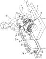
図1を参照すると、模式的斜視図において、全体を通して参照番号10によって表示される、本発明のある実施態様による光活性化装置が示される。光活性化装置10は、所定の1組の光活性化光パラメータを有する光活性化光を、標的人体の治療領域に向けることによって標的生物活性の生理を変調させるために主に使用されるように適応される。本文を通じて光活性化の例は主に標的生物活性の生理を光的に誘発することになるが、光活性化は、本発明の範囲から逸脱することなく、標的生物活性の光阻害をもたらすことも可能であることを理解しなければならない。 Referring to FIG. 1, in a schematic perspective view, a photoactivation device according to an embodiment of the present invention is shown, indicated by
図1において、光活性化装置10は、治療ベッド16に横たわる治療に適応した患者14の顔面領域12を治療するために使用されているところが示される。光活性化装置10は、近くに立つオペレータ18によって操作されるところが示される。しかしながら、光活性化装置10は、本発明の範囲から逸脱することなく、別の背景においても、例えば、他の治療領域を治療するためにも使用することが可能であることを理解しなければならない。例えば、図4は、光活性化装置10が、腰掛けている患者14の、背中上部領域20を治療するために使用されているところを示す。 In FIG. 1, the
光活性化装置10は治療ヘッド22を含む。順に、治療ヘッド22は、光活性化光を発射する光活性化光源を含む。光活性化装置10はまた、机上、床等の支持面に装置10を支持するための装置基礎24を含む。更に、装置10は、治療ヘッド22を装置基礎24に機械的に結合し、かつ、装置基礎24に対する治療ヘッド22の選択的相対移動を可能にするための基礎−ヘッドアームアッセンブリ26を含む。 The
図1から5及び8に更に具体的に示されるように、基礎−ヘッドアームアッセンブリ26は、通常、アッセンブリ第1アーム28とアッセンブリ第2アーム30とを含む。アッセンブリ第1アーム28は、第1アーム第1末端32と、長軸方向の反対位置にある第1アーム第2末端34を定める。図2に更に具体的に示すように、アッセンブリ第1アーム28は、装置基礎24に対し、第1アーム第1末端32に実質的に近接して軸回転的に結合し、それによって、所定の第1アーム回転範囲38において、実質的に垂直な第1アーム回転軸36の周囲を、装置基礎に対して軸回転することが可能とされる。 As more specifically shown in FIGS. 1 to 5 and 8, the foundation-
図2は、第1アーム回転範囲38が約180度の値を有するものとして描いている。しかしながら、第1アーム回転範囲38は、本発明の範囲から逸脱することなく他の値を取ることも可能であることを理解しなければならない。 FIG. 2 depicts the first
アッセンブリ第2アーム30は、第2アーム第1末端40と、長軸方向の反対位置にある第2アーム第2末端42を定める。アッセンブリ第2アーム30は、アッセンブリ第1アーム28に対し、第2アーム第1末端40に実質的に近接して軸回転的に結合し、それによって、実質的に垂直な第2アーム垂直回転軸44、及び実質的に水平な第2アーム水平回転軸46の周囲を、アッセンブリ第1アームに対して軸回転することが可能とされる。第2アーム垂直回転軸44の周囲におけるアッセンブリ第2アーム30の回転は、図2に示す所定の第2アーム水平回転範囲48の間許される。水平回転軸46の周囲における第2アーム30の回転は、図3に示す所定の垂直回転範囲50の間許される。 The assembly
第2アーム水平回転範囲48は、図2では約225度の値を有するものとして描かれる。第2アーム垂直回転範囲50は、図3では総合値約75度を有するものとして描かれる。第2アーム垂直回転範囲の第1分節52は、基準水平面Pから約30度全体として下方に延び、その第2分節54は、基準水平面Pから約45度全体として上方に延在する。 The second arm
しかしながら、第2アーム水平及び垂直回転範囲48、50、及び第2アーム垂直回転範囲50の第1及び第2分節は、本発明の範囲を逸脱することなく他の値を取ることも可能であることを理解しなければならない。また、アッセンブリ第1及び第2アーム28、30は、通常、それぞれ約32 cmと82 cm長さを有するが、アッセンブリ第1及び第2アーム28、30は、本発明の範囲を逸脱することなく他の値を取ることも可能である。 However, the second arm horizontal and vertical rotation ranges 48 and 50, and the first and second segments of the second arm
基礎−対−ヘッドアームアッセンブリ26は通常また、アッセンブリ第2アーム30に機械的に結合した重量補償アッセンブリ又は手段を含む。このアッセンブリ又は手段は、治療ヘッド22の重量を少なくとも部分的に補償し、アッセンブリ第2アーム30が、治療ヘッド22の重量を受けて、第2アーム水平回転軸46の周囲に軸回転するのを防止するためのものである。図面を通して示される実施態様では、重量補償手段は空気圧シリンダー56を含む。しかしながら、重量補償手段は、本発明の範囲を逸脱することなく、適当なものであれば他の、任意の形態、例えば、弾性的に変形可能な部材、効果的に配置された補償錘等の形態を取ることも可能であることを理解しなければならない。 The base-to-
基礎−対−ヘッドアームアッセンブリ26は通常更に、第2アーム第2末端42に実質的に近接するアッセンブリ第2アーム30と治療ヘッド22の間に延在する、アーム−対−ヘッド万能型機械結合又はスイベル58を含む。これは、治療ヘッド22をアッセンブリ第2アーム30に機械的に結合し、該アームに対して軸回転及び回転を可能にするためのものである。基礎−対−ヘッドアームアッセンブリ26は通常更に、アーム−対−ヘッドの解除可能なロックアッセンブリ又は手段を含む。これは、治療ヘッド22を、アッセンブリ第2アーム30に対してヘッド動作位置に解除可能にロックするためのものである。このアーム−対−ヘッドスイベル及びアーム−対−ヘッドロック手段は、本発明の範囲から逸脱することなく任意の適当な形態を取ることが可能である。本発明の一つの実施態様では、アーム−対−ヘッド機械結合58は、ボール及びソケット型ジョイントを形成するように、対応するスイベルソケット62の内部に取り付けられたスイベルボール60を含む。スイベルの隙間分節64が、スイベルボール60から延びて治療ヘッド22に取り付けられている。 The base-to-
アーム−対−ヘッド機械結合58は、通常は、治療ヘッド22が、三次元のスイベル範囲70の中を自由に回転することを可能とする万能型である。スイベル範囲70は、図4では、一つの平面において約115度の値を有するものとして描かれているが、スイベル範囲70はまた、複数の平面を横断して動くことも可能で、その際、各平面のスイベル範囲は同じ又は別の値を取ることも可能である。従って、治療ヘッド22を、図4に描かれる平面の中に回転することも、平面から外に回転することも可能である。更に、スイベル範囲は、本発明の範囲から逸脱することなく他の値を取ることも可能である。アーム−対−ヘッド機械結合58はまた通常、スイベルの隙間部品64の長軸と実質的に共軸的に延在するヘッド回転軸に対して治療ヘッド22が回転するのを可能とする。従って、機械結合58は、治療軸22が一軸の周囲に回転することを可能とし、それによって、治療ヘッド22を、第2アームに対してのみならず、基礎24に対しても任意の角度で位置づけることを可能とする。 The arm-to-head mechanical coupling 58 is typically a universal type that allows the
アーム−対−ヘッド解除可能ロック手段は通常、ノブ61等を用いることによってスイベルソケット62とスイベルボール60との間の摩擦を増すための手段を含む。アーム−対−ヘッド解除可能ロック手段は、適当であれば、任意の他の形態、例えば、スイベルボール60に選択的に摩擦的に係合する形態に変化するように適応した温度依存性記憶合金の使用を含む形態を取ることも可能である。 Arm-to-head releasable locking means typically includes means for increasing friction between swivel socket 62 and
装置10は通常また、基礎−対−ヘッドアームアッセンブリ26と治療ヘッド22の間に延在するアーム−対−ヘッド解除可能電気結合66において、治療ヘッドに解除可能に電気的に結合する結合を含む。アーム−対−ヘッド解除可能電気結合66は、治療ヘッド22が、基礎−対−ヘッドアームアッセンブリ26の一部、例えば、スイベル隙間部品64に対し速やかで、簡単で、エネルギー的な結合の実現を可能とすることが好ましい。これによって、次に、治療される領域、光活性作用の所望のタイプ、又はその他の動作パラメータに応じて、治療ヘッドの位置を特注的に合わせることが可能となる。 The
例えば、図1、2、3、5、21、及び30は、対象患者14の顔面領域12を治療するように適応した実質的に弓状の治療ヘッド22を示し、一方、図4及び31は、対象患者14の背部領域20を治療するように適応した全体として凹型ではあるが、比較的平坦な治療ヘッド22を示す。更に、弓状治療ヘッド22は、対象患者14の付属器官、例えば、腕及び脚、又はその他の生体部分、例えば、対象患者14のでん部又は個々の乳房を部分的に囲み、治療するのに使用することが可能である。更に、「平坦な」治療ヘッド22は、患者14の胸部や側方を治療するために使用することが可能であり、より大きな表面積を治療するような寸法を取ることも可能である。本発明の範囲から逸脱することなく、他の形態を有する他のタイプの治療ヘッド22を使用することも可能であることを理解しなければならない。 For example, FIGS. 1, 2, 3, 5, 21, and 30 show a substantially
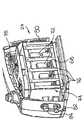
更に具体的に図6及び7に示すように、装置基礎24は通常、全体を通じて参照番号68で呼ばれる装置電源の少なくとも一部を保護的に収容する。電源68は、通例のファラデー型ケージ74内に搭載される、少なくとも1個、通常は4個の電源ユニット72を含む。ファラデー型ケージ74はまた、少なくとも1個、通常は4個のリレー部品76を含む。 More specifically, as shown in FIGS. 6 and 7, the
装置基礎24内に収容される部品を換気するために、通常、装置基礎換気アッセンブリ又は手段が供給される。装置基礎換気アッセンブリ又は手段は、通常、ファラデーケージ74の上に取り付けられる、少なくとも1基の、好ましくは2基の換気扇78を含む。装置基礎ファン78は、基礎換気グリッド80を通して風を吹くことによって装置基礎24内に収容される部品を対流的に冷却するように適応される。 In order to ventilate the parts housed in the
通常、装置基礎24からは、オンオフスイッチ82及び緊急停止スイッチ84が延在している。これは、それぞれ、対象ユーザーが、緊急時に装置10をオン及びオフしたり、装置10を速やかに切るためのものである。 Normally, an on / off
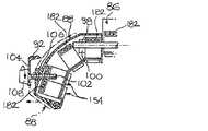
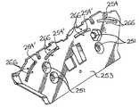
ここでより具体的に図9から12、21及び30を参照すると、ヒト顔面領域の治療用に意図される治療ヘッド22の特質のいくつかがより具体的に示される。通常、治療ヘッド22は、少なくとも2個の、好ましくは3個の頭部セクションを含む。各頭部セクションには通常、光活性化光を発射する光活性化光源154が設けられる。通常、頭部セクションの内の少なくとも二つは相互に可動である。更にこの後でより詳細に開示されるように、頭部セクションの内の少なくとも2個が相互に可能である状況では、各可動頭部セクションはまた、対応セクションの光活性化光源154と動作するように結合するセクション位置決め手段を含む。これは、対応する標的表面セクションに対する対応セクション光活性化光源154の選択的位置取りを可能にする。 Referring now more specifically to FIGS. 9-12, 21, and 30, some of the characteristics of the
言い換えると、光活性化光が向けられる標的表面は、通常、いくつかの標的表面セクションに分割することが可能であり、治療ヘッドは、それぞれが、対応セクション光活性化光源154を有する、対応ヘッドセクションに分割される。更に、個々のヘッドセクション、従って、対応する個々のセクション光活性化光源154は、標的表面の個々のセクションに対して最適治療を施すことができるように、相互に相対的に動くことが可能とされる。 In other words, the target surface to which photo-activated light is directed can typically be divided into several target surface sections, and the treatment heads each have a corresponding section photo-activated
図30に模式的に描かれるように、ヒト顔面領域12の治療に使用されることを意図される治療ヘッド22は、通常、中央ヘッドセクション86と、一対の側方ヘッドセクション88を含む。側方ヘッドセクション88は、中央セクション86の各側に配置される。更に、側方ヘッドセクション88の少なくとも片方、好ましくは両側方ヘッドセクション88は、中央ヘッドセクション86に対して外側に変位させることが可能である。側方ヘッドセクション88と中央ヘッドセクション86の間の相対的移動を示すために、図30の上部に見える側方ヘッドセクション88は、中央ヘッドセクション86に対して接近関係にあるものとして描かれるが、一方、図26の下部に見える側方ヘッドセクション88は、中央対側方ヘッドセクション間隙90によって中央ヘッドセクション86に対して隔てられるところが示される。これによって、側方ヘッドセクション88は、患者14の顔のサイズ及び/又は形によらず顔面領域12に対して同じ距離を維持することが可能になる。 As schematically depicted in FIG. 30, a
図1、2、及び8から12において更に具体的に描かれるように、治療ヘッド22は通常ヘッド基盤92を含む。ヘッド基盤92は通常、把捉可能なヘッド基盤ハンドルセクションを定める。図面全体を通じて示される実施態様では、把捉可能なヘッド基盤ハンドルセクションは、ヘッド基盤92の各側に配される対応する近接ハンドルセクション開口96によって少なくとも部分的に区切られる一対のハンドルセグメント94を含む。ハンドルセグメント94は、治療ヘッド22の手動による位置決めが可能となるように、対象オペレータ18の手によって把捉が可能な形と寸法を有すると好都合である。 As depicted more specifically in FIGS. 1, 2, and 8-12, the
通常、中央ヘッドセクション86はヘッド基盤92に固定される。中央及び側方ヘッドセクション86、88には、その二つの間に動作するように結合して、側方ヘッドセクション88の、中央ヘッドセクション86に対する側方移動を案内するための協調側方誘導アッセンブリ又は手段が設けられる。更に、治療ヘッド22には通常、中央ヘッドセクション86に対して側方ヘッドセクション88を側方に移動させるために、ヘッド基盤92と側方ヘッドセクション88との間に動作するように結合する側方移動アッセンブリ又は手段が設けられる。 Usually, the
図11及び12により具体的に描かれるように、側方誘導アッセンブリ又は手段は通常、中央ヘッドセクション86に取り付けられ、それから側方、中央ヘッドセクションの反対側に延在する、少なくとも1本の誘導ロッド98、好ましくは2本の誘導ロッド98を含む。側方誘導アッセンブリ又は手段はまた、各側方ヘッドセクション88に取り付けられている対応する誘導スリーブ100を含む。各誘導スリーブ100は、対応する誘導ロッド98の対応セクションを滑走的に受容するための対応誘導通路を定める。 As depicted more specifically in FIGS. 11 and 12, the side guide assembly or means is typically attached to the
図10及び11により具体的に描かれるように、側方移動アッセンブリ又は手段は通常、一対の側方移動ネジ102(図11ではその内の1本のみが示される)を含む。各側方移動ネジ102は、ヘッド基盤92に対して回転可能となるようヘッド基盤に機械的に結合され、対応する側方ヘッドセクション88に対してネジ溝を通じて結合し、その回転によって該側方ヘッドセクションを移動させる。 As illustrated more specifically in FIGS. 10 and 11, the lateral movement assembly or means typically includes a pair of lateral movement screws 102 (only one of which is shown in FIG. 11). Each
図1、5、10、及び11により具体的に描かれるように、ヘッド基盤92には通常、それから延在する一対のネジ間隙アーム104が設けられる。これは、側方移動ネジ102を回転的に受容するためのものである。更に、各側方ヘッドセクション88には通常、対応する側方移動ネジ102と螺合するために、対応する側方ネジ溝セクション106が設けられる。 As illustrated more specifically in FIGS. 1, 5, 10, and 11, the
各側方移動ネジ102には通常、その手動による回転を促進するために側方ネジノブ108が設けられる。いずれかの側方ネジノブ108が回転すると、対応する側方移動ネジ102と対応する側方ネジ溝セクション106の間の螺合によって、対応する側方ヘッドセクション88が、対応する間隙アーム104に対して、従って、中央ヘッドセクション86に対して移動させられる。 Each
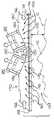
本発明の少なくとも一つの実施態様では、治療ヘッド22は、標的ヒト顔面12の形態に実質的に一致するような構成と寸法を有する。通常、治療ヘッド22は、標的ヒト顔面12が、女性の低い方の5パーセンタイルと、男性の高い方の95パーセンタイルの間に収まる人体計測値又は寸法値を有する場合、その標的ヒト顔面12の形態に実質的に合致するような構成と寸法を有する。 In at least one embodiment of the present invention, the
図30は、それぞれ、寸法において5パーセンタイルに相当する女性と、95パーセンタイルに相当する男性の、互いに接合された半分頭部矢状断面を模式的に示したものである。この女性と男性の半分頭部矢状断面112、114は、鼻110のレベル付近の中間平面において横に切断されたところが示されている。女性の半頭断面112は図30の上方部分に現れ、男性の半頭断面114は図30の下方部分に現れる。従って、図30は、女性の5パーセンタイルと男性の95パーセンタイルの間の値を有する頭部サイズを治療する場合に、治療ヘッド22が、サイズ差を受け容れるために、対応する必要のあるサイズの変動を表す。 FIG. 30 schematically shows half-head sagittal sections joined to each other of a female corresponding to the 5th percentile and a male corresponding to the 95th percentile in size. The female and male half-head
ヒトの顔面は、一対の耳116(図30にはその内の一つしか示されない)と一対の眼(図示せず)を含む。各眼は、側方に配される眼窩周辺域118を定め、一方、各耳116は、対応する側頭耳介周辺域120を定める。通常、側方眼窩周辺域118は、頬骨突起域に一致し、皺又は、一般にカラスの足と呼ばれる小皺が通常現れる領域に一致する。 The human face includes a pair of ears 116 (only one of which is shown in FIG. 30) and a pair of eyes (not shown). Each eye defines an
例えば、図30を参照すると、ヒトの顔面12は通常、側方眼窩周辺域118の間に位置する面積に実質的に延在する顔面中央域122を定める。ヒトの顔面はまた、それぞれ、側方眼窩周辺域118と、対応する側頭耳介周辺域120との間に位置する領域に実質的に延在する一対の側方顔面域124を定める。 For example, referring to FIG. 30, the
図21及び30により具体的に描かれるように、治療ヘッド22は通常、標的ヒト顔面12に向き合うように適応したヘッド近位面126を定める。ヘッド近位面126は、標的ヒト顔面12に対して、実質的に標的ヒト顔面の治療期間を通して、実質的に定常なヘッド表面対標的面操作距離128に位置し続けるような構成と寸法を有する。 As illustrated more specifically in FIGS. 21 and 30, the
通常、治療ヘッド22は、光活性化光源154が、標的ヒト顔面12に対し、実質的にその治療期間を通じて実質的に定常な光源対標的面操作距離に位置し続けるような構成と寸法を有する。従って、比較的定常なフルエンスを有する光活性化光源154では、治療ヘッド22は、治療領域に対し実質的に定常な照射力(又は光学パワー密度)を有する光活性化光を発する構成と寸法を有する。従って、標的ヒト顔面12が女性の5パーセンタイルと男性の95パーセンタイルの間に位置する人体計測値を有する場合、側方ヘッドセクション88の側方移動によって通常、治療ヘッド22は、標的ヒト顔面12に対して定常な標的照射力を有する光活性化光を発射することが可能になる。 Typically, the
更に、中央ヘッドセクション86は通常、鼻領域に光活性化光を発射するように適応され、従って通常、側方ヘッドセクションに対しては外方にずれる。更に通常、側方ヘッドセクション88の少なくとも一つ、好ましくは両側方ヘッドセクション88は、実質的に弓状の断面形を有する。各側方ヘッドセクション88は通常、鼻110から側方に、対応する側頭耳介周辺域120に向かって延在する対応領域に光活性化光を発射するための構成と寸法を有する。 In addition, the
図21と30により具体的に示されるように、本発明の少なくとも一つの実施態様では、各側方ヘッドセクション88は、鼻110に側方に実質的に近接する第1位置から、対応する側方眼窩周辺域118に対して側方実質的に近位に位置する第2位置に向けて延在する、対応する側方顔面セクション第1分節に対して光活性化光を発射するための側方ヘッドセクション第1分節130を定める。 As shown more specifically in FIGS. 21 and 30, in at least one embodiment of the present invention, each
各側方ヘッドセクション88はまた、第2位置から、対応する側方眼窩周辺域118の側方に位置する第3位置に延在し、対応側方眼窩周辺域118を実質的に横断して延在する、対応側方顔面セクション第2分節に対して光活性化光を発射するための、側方ヘッドセクション第2分節132を定める。各側方顔面セクション88は更に、第3位置から対応側頭耳介周辺域120に実質的に延在する、対応側方顔面セクション第3セグメントに対して光活性化光を発射するための、側方ヘッドセクション第3分節134(図21ではその一部しか示されていない)を定める。 Each
通常、側方ヘッドセクション第1、2、及び3分節130、132、及び134には、第1、2、及び3分節光源が設けられる。第1、2、及び3分節光源は、実質的に治療領域全体を通じて、標的ヒト顔面12に対して、実質的に定常な光源対標的表面操作距離に存続するように位置決めすることが可能である。 Typically, the side head sections first, second, and
図を通して示される実施態様では、側方ヘッドセクション第1及び第2分節130、132には両方とも、少なくとも1列の光活性化光源154が設けられており、側方ヘッドセクション第3分節134には、横並列の一対列の光活性化光源154が設けられる。通常、側方ヘッドセクション第1、2、及び3分節130、132、及び134の光活性化光源列154は、実質的に定常なビームサイズとビーム分散を示す、実質的に定常なフルエンスを供給する。選択的に、本発明の範囲から逸脱することなく、上記及びその他の光学的パラメータの内のいくつか、或いはその全てを目的に合わせて特注してもよい。 In the embodiment shown throughout the figure, the side head section first and
ここでより具体的に図16及び17を参照すると、典型的な光活性化光源154の特質のいくつかが示される。本発明の少なくとも一つの実施態様では、光活性化光源154は、対応するプリント回路基板(PCB)の搭載表面に直接搭載される電子発光部品を含むチップオンボード(COB)型である。通常、電子発光部品としては少なくとも1個のLEDが挙げられるが、実質的に長方形のLEDマトリックス138を含むことが好ましい。図17では、LEDマトリックス138を構成する一対のLED136しか示されていない。更に、LED136は、LEDマトリックス138の残余部分に対して拡大して示されている。更に、LED136は、実質的に円盤型の断面形を有するものとして示されている。しかしながら、他のタイプのLED136も、本発明の範囲から逸脱することなく使用が可能であることを理解しなければならない。例えば、通常、LEDマトリックス138は実質的に平坦なLEDストリップから成る。この場合も、本発明の範囲から逸脱することなく他のタイプの発光部品を使用することが可能であることを理解しなければならない。 Referring now more specifically to FIGS. 16 and 17, some of the characteristics of a typical light-activated
ある実施態様では、LEDマトリックス138は複数列及び複数行のLEDから成る。このマトリックスは、等しい或いは等しくない数の列と行を有することが可能である。更に、各列及び行は、隣接の列又は行と比べて異なる数のLEDを有することも可能である。各列又は行は、同時に発光してもよいし、或いは「カスケード的に」発光してもよい。LEDは、ヒトの眼には同時として保存されるほど速やかにカスケード発光することも可能である。LEDマトリックスは、不必要な暴露無しに光線を供給することができるよう、治療ヘッド22の特定の領域又は形に合わせた形態を取るように設計することが可能である。更に、LEDマトリックスのセクションは、全ての治療に対しその全てが必ずしも点灯する必要はなく、一列置き一行置きに点灯したり、或いは、特定の治療においてはいくつかは全く点灯しなくともよい。 In one embodiment, the
通常、光活性化光源154はまた、電子発光部品138によって発射される光活性化光線142(図30と31に模式的に示される)を誘導するために、電子発光部品138に光学的に結合するレンズを含む。これによって、光活性化光源154は、所定の光発射パターンに従って光活性化光を発射することが可能になる。図面を通して示される例では、レンズは、光活性化光線142を集束するために用いられる。しかしながら、レンズはまた、使用する発光部品のタイプによっては、光活性化光線142を分散させるために用いてもよいことを理解しなければならない。 Typically, the light activated
通常、レンズは、実質的に長方形のレンズプレート140を含む。レンズプレート140は通常、COBケーシング143によってLEDマトリックス138に対して遊離関係に維持される。 Typically, the lens includes a substantially
レンズプレート140は、一対の、長軸方向に延在するレンズプレート側縁144を定める。COBケーシング143は通常実質的に長方形を有し、一対の、長軸方向に向き合う、COBケーシングの長軸端146を定める。COBケーシング143はまた、一対の、長軸方向に延在するCOBケーシング側壁148を定める。 The
各COBケーシング側壁148は通常、対応するレンズプレート側縁144に対し実質的に接近関係にある。COBケーシング側壁148は、ケーシングの長軸端146近くで外側方に広がり、対応するCOBケーシング連結フランジ150を形成する。 Each
通常、COBケーシング連結フランジ150には、下記により具体的に開示するように、対応するCOBケーシング143を適当な支持表面取り付けに用いるのに適応した通例の連結部品、例えば、ネジを受容するために貫通して延在する連結口152が設けられる。 Typically, the COB
図20により具体的に描かれるように、光活性化光源154は通常、ペアとして、横並びに相接して配せられ、それぞれの連結フランジ150は互いに近接関係に置かれる。この構成では、側方に隣接する光活性化光源154の、対応する隣接ケーシング側壁148の残部が、その間にCOBケーシング冷却チャンネル156を区画する。これによって、より具体的に後述するように、冷却液がそのチャンネルを通じて流れることが可能になる。 As illustrated more specifically in FIG. 20, the light-activated
通常、各光活性化光源154は、通常COBケーシングの長軸端146の一つに隣接して配される制御電子部品158を含む。COBケーブル160は通常、それの適当なコネクターへの接続を可能とするためCOBケーシング143の下面から延在する。光活性化光源モジュールの密封は通常、電子コントロール158に向き合うCOB長軸端146に配せられる自己接着性テープ162によって実現される。 Each light-activated
通常、各光活性化光源154は、実質的に0.04 W/cm2を上回る標的照射、約0.05から10 J/cm2の標的フルエンス、及び所定のパルスパターンを有する、パルス状光活性化光を発射するように設計される。より具体的には、標的照射は通常、LEDの中央において約0.05 W/cm2の値を有し、標的フルエンスは約4 J/cm2の値を有する。特に、ある実施態様は、4 J/cm2以上の標的フルエンスを用いる。別の実施態様は4.5から10 J/cm2のフルエンスを用いる。Typically, each light-activated
光活性化光源154によって発射される光活性化光は通常、約600 nmと700 nmの間の波長値を有する。より具体的には、光活性化光は通常、約660 nm±10 nmのピーク波長値を有する。 The photoactivated light emitted by the photoactivated
光活性化光源154のパルスパターンは通常、約0.0005秒のパルス幅と、約0.00015秒のパルス間隔を有するパルスを含む。通常、所定のパルスパターンはまた、約3から5個のパルスから成るパルス列において、約0.00155秒のパルス列間隔を有するパルス列を含む。本発明の範囲から逸脱することなく他のパルスパターンを用いることも可能であることを理解しなければならない。 The pulse pattern of the light activated
通常、標的照射がLEDアレイの中央で約0.05 W/cm2、標的フルエンスが約4 J/cm2である場合、ヘッド表面対標的表面操作距離128は、約2.5 cm ± 1から3 mmの値を有する。しかしながら、ヘッド表面対標的表面操作距離128は、本発明の範囲から逸脱することなく別の値を取ることも可能であることを理解しなければならない。Typically, if the target illumination is about 0.05 W / cm2 at the center of the LED array and the target fluence is about 4 J / cm2 , the head surface to target
上述の因子が相互に関連するので、全てが組み合わさって様々な照射を生じる。例えば、電力密度0.05 W/cm2、パルス幅0.005秒、パルス間隔0.00015秒、パルス列間隔0.00155秒の4個パルス−パルス列で、合計160秒を有するLEDアレイは、合計500 W/cm2の照射を生じる。上記パラメータの内の任意の一つを変更することで照射を変えることが可能であり、或いは、異なるパラメータを変えることが同じ照射をもたらすことも可能である。Since the above factors are interrelated, all combine to produce a variety of irradiations. For example, an LED array with a total of 160 seconds with a power density of 0.05 W / cm2 , a pulse width of 0.005 seconds, a pulse interval of 0.00015 seconds, a pulse train interval of 0.00155 seconds, and a total of 160 seconds will deliver a total of 500 W / cm2 illumination. Arise. It is possible to change the illumination by changing any one of the above parameters, or changing different parameters can result in the same illumination.
通常、と言って必ずそうなると言うのではないが、光活性化光源の焦点許容度は、約±3度の値で、約50±5度のビーム分散(FWHM)値を有する。スペクトラム幅(FWHM)は、約30±5 nmの値を有する。レンズプレート140は通常円筒型であり、レンズ材料として例えばUL94 V-2ポリカーボネートを用いる。 Usually, this is not necessarily true, but the focus tolerance of the light activated light source is about ± 3 degrees and has a beam dispersion (FWHM) value of about 50 ± 5 degrees. The spectrum width (FWHM) has a value of about 30 ± 5 nm. The
図32と33は、それぞれ、単一光活性化光源154、及び、3列の隣接光活性化光源154によって生成された典型的照射パターンを示す。これらの図から見て取れるように、光パワー密度、すなわち照射は、照明範囲を通じて実質的に定常である。 32 and 33 show typical illumination patterns generated by a single photoactivated
通常、最大−最小偏差は、光活性化光源154の長軸に沿って15パーセンタイルの桁である。更に、光活性化光源154は、その寿命を通じて、照射、すなわち光パワー密度が比較的定常を持続するように設計されることが好ましい。例えば、光活性化光源154は、照射が、2000時間の動作後にも最初の照射の85パーセンタイル未満に落ちることがないように設計される。本発明の範囲を逸脱することなく、他の光学的、機械的、電気的、又はインターフェイス特性を有する、他のタイプの光活性化光源を使用することが可能であることを理解しなければならない。 Typically, the maximum-minimum deviation is on the order of 15th percentile along the long axis of the light-activated
前述したように、ヘッド近位面126は通常、ヘッド表面対標的表面操作距離128によって、標的ヒト顔面12から隔てられる。従って、図19により具体的に描かれるように、治療ヘッド22と治療領域は通常、その間に、治療ヘッド対治療領域空間164を定める。 As described above, the head
通常、治療ヘッド22はまた、治療領域を冷却するための、治療領域冷却アッセンブリ又は手段を含む。本発明の一つの実施態様では、治療領域冷却アッセンブリ又は手段は、治療領域を冷却するために、少なくとも部分的に治療ヘッド対治療領域空間164を流れる治療領域気流168を生ずるための冷却送風アッセンブリ又は手段を含む。治療領域気流168は、治療領域を対流的に冷却することによって、及び/又は、治療ヘッド対治療領域空間164から熱を追放することによって治療領域を冷却するように適応する。治療領域気流168はまた、対象患者14の呼吸によって生産される一酸化炭素及び/又はその他の副産物の追放を可能とするように適応する。 Typically, the
図全体を通じて示される実施態様では、治療ヘッド対治療領域空間164から空気を吸引する、又は、引き込むことによって治療領域気流168を誘発する。本発明の別の実施態様では、治療ヘッド対治療領域空間164に空気を吹き込むことによって治療領域気流168を誘発する。 In the embodiment shown throughout the figure, the
治療領域気流168が、治療ヘッド対治療領域空間164に冷却空気を吹き込むことによって誘発されたのか、或いは、治療ヘッド対治療領域空間164から冷却空気を吸引又は引き込むことによって誘発されたのかとは無関係に、冷却空気は、その冷却作用を更に強調するために、選択的にあらかじめ冷却してもよい。冷却空気を患者14に吹き付けても、或いは、過加熱空気を患者14から吸引しても、いずれも患者14の皮膚に対して冷却作用をもたらす。これは患者を慰安するばかりでなく、皮膚を涼しくして患者14が過加熱又は汗まみれになることを防止する。 Regardless of whether
更に、選択的に、冷却空気を、各種薬剤、例えば、治療薬剤、光活性化促進剤等と混合してもよい。更に、冷却空気は、選択的に、麻酔剤、例えば、少なくとも部分的に患者を鎮静させるために鎮静剤と、治療部位等の局所麻酔を少なくとも部分的に実現するために局所麻酔剤と混合してもよい。 In addition, the cooling air may optionally be mixed with various drugs such as therapeutic drugs, photoactivation accelerators and the like. In addition, the cooling air is optionally mixed with an anesthetic such as a sedative to at least partially sedate the patient and a local anesthetic to at least partially achieve local anesthesia such as the treatment site. May be.
通常、治療ヘッド22はまた、光活性化光源154を冷却するための光源冷却アッセンブリ又は手段を含む。通常、光源冷却アッセンブリ又は手段は、光活性化光源154及び関連部品を対流的に冷却するために光源気流166を生成するための装置冷却送風アッセブリ又は手段を含む。図13-20を通じて描かれる実施態様では、装置冷却送風アッセンブリ又は手段はまた、治療領域を冷却するために治療領域気流168を生成する。より具体的には、光源気流166は真空を造り出し、これが治療領域気流168を誘発する。それとは別に、光源気流166と治療領域気流168を別々に誘発してもよい。 Typically, the
図16、18、及び19により具体的に描かれるように、光活性化光源154は通常、ヒートシンク170に熱的に結合する。冷却送風アッセンブリ又は手段によって、光源気流166は、ヒートシンク170を冷却し、ヒートシンク170を横切って真空を発生させ、それによって治療領域気流168を誘発することが可能になる。ヒートシンク基盤プレート172は、ヒートシンク基盤プレート第1面174と、反対側の、ヒートシンク基盤プレート第2面を定める。ヒートシンク基盤プレート172は、それを貫通する少なくとも1個の、好ましくは複数の空気流通口178を有する。空気流通口178は、特定の気流を形成するように所定のパターンに配置することも可能であるし、ランダムに設置することも可能である。 As specifically illustrated by FIGS. 16, 18 and 19, the light-activated
冷却送風アッセンブリ又は手段により、光源気流166は、ヒートシンク基盤プレート第1面174の少なくとも一部、好ましくはその多くの上に流れ、ヒートシンク基盤プレート第2面176から空気流通口178を通じて治療領域気流168を引き込む真空を生成することが可能となる。 By means of a cooling blast assembly or means, the
通常、ヒートシンク170はまた、ヒートシンク基盤プレート第1面174から延在する熱拡散フィン180を含む。熱拡散フィン180は、その間にフィンチャンネル184を定める。冷却送風アッセンブリ又は手段は、光源気流166が、熱拡散フィン180の間を少なくとも部分的に流れることを可能にする。通常、冷却送風アッセンブリ又は手段は、フィンチャンネル184と流通する少なくとも一つの空気ファン182を含む。 Typically, the
図15、16、18、及び19により具体的に描かれるように、熱拡散フィン180は、少なくとも1個の、好ましくは2個のファン受容溝186を定めるように構成される。ファン受容溝186は、対応する換気ファン182を少なくとも部分的に受容するように適応される。ファン受容溝186は通常、少なくとも1個の、好ましくは二つの空気ファン182が、ヒートシンク基盤プレート172と熱拡散フィン180に対してある角度をもって配されるような構成、配置、寸法を有する。 As specifically illustrated by FIGS. 15, 16, 18, and 19, the
通常、治療ヘッド22は、互いに並列関係に配された、複数のヒートシンク170を含む。各ヒートシンク170は対応するヒートシンク基盤プレート172を含み、各ヒートシンク基盤プレート172は、一対の長軸方向に向き合う基盤プレート長軸端188の間に延在する実質的に長方形の形を有する。熱拡散フィン180は、対応するヒートシンク基盤プレート172に沿って実質的に長軸方向に延在する。 Typically,
ファン受容溝186は通常、プレートの長軸端188の実質的に中間に配される。図18及び19により具体的に描かれるように、空気ファン182は、互いに実質的に対称的に向き合う関係で存在するように配される。各空気ファン182は、対応する基盤プレート長軸端188から、対応する光源気流部分を引き込むように配される。 The
図19により具体的に描かれるように、各1対の空気ファン182は、その間にファン対ファン空間190を定める。空気ファン182は、それらの引き込む冷却空気部分が、模式的に表され、参照番号192によって表示される流動パターンに従ってファン対ファン空間190に浸透するような構成、寸法、及び配置を有する。空気ファン182によってファン対ファン空間190に引き込まれた空気の流動パターン192は、その下部に配される、ヒートシンク基盤プレート172部分の冷却を可能とする。それとは別に、空気ファン182は、ヒートシンク170と流通し、ファン受容溝186に収容した場合と同じように機能を実行できるように配された基礎24、又は別の筐体(図示せず)の中に設置することも可能である。 As illustrated more specifically in FIG. 19, each pair of
図10及び20により具体的に描かれるように、COBケーシング143は、ヒートシンク基盤プレート第2面176の上に取り付けられる。その際、COBケーシング冷却チャンネル156は、空気流通口178の少なくともいくつかと実質的に連通し、それによって空気が、ヒートシンク基盤プレート第1面174からヒートシンク基盤プレート第2面176に流れるようにする。図19により具体的に描かれるように、空気ファン182が、光源気流166を、ヒートシンク基盤プレート第1面174の上に引き込むと、空気流通口178の中に真空が生成される。この真空が、COBケーシング冷却チャンネル156と、それと連通する対応空気流通口178の両方を通じて、ヒートシンク基盤プレート第2面176から治療域気流168を吸い込み、そのために、治療域気流168は、ヒートシンク基盤プレート第1面174上で、最終的に光源気流166と合流する。 As illustrated more specifically in FIGS. 10 and 20, the
図20により具体的に描かれるように、治療ヘッド22は通常、互いに、実質的に並列接触関係にある複数列199の光活性化光源154を含む。各列199は通常、一対の光活性化光源154を、それぞれの長軸を互いに実質的に平行関係において隣接させることによって形成される。選択的に、空気流通スロット196が、長軸方向に隣接する光活性化光源154の間のヒートシンク基盤プレート172を貫いて延在する。 As illustrated more specifically in FIG. 20, the
図11により具体的に描かれるように、中央ヘッドセクション86と側方ヘッドセクション88には、それぞれ、意図的に配された、独立組の光学プローブ空気ファン182が設けられる。それぞれ、中央ヘッドセクション86と側方ヘッドセクション88によって形成されるケーシングに吸引された空気は、対応する対の長軸方向に向き合う中央及び側方空気流入グリッド181、183を通じて流れるように適応される(図5に、各対の空気流入グリッド181、183の内一方の流入グリッド181、183部分のみが示される)。 As depicted more specifically in FIG. 11, the
図9により具体的に描かれるように、中央ヘッドセクション86によって形成されるケーシングから流れ出る空気は、スクリーン194とは実質的に長軸方向に反対側に配される、対応する中央空気流出グリッド185を通じて流れるように適応される。図1、5、及び9により具体的に描かれるように、各側方ヘッドセクション88によってケーシングから流出する空気は、対応する、実質的に放射方向に配される側方空気流出グリッド187を通じて流れるように適応される。 As illustrated more specifically in FIG. 9, the air flowing out of the casing formed by the
本発明の別の実施態様では、熱拡散アッセンブリ又は手段はいわゆる熱拡散器を含む。後者は、半導体金型から、金型パッケージを出るリードへ熱を導く部材に関わる。装置を冷却するにはヒートシンクと熱拡散器を一緒に用いてもよい。その他の形の熱拡散手段も、本発明の範囲から逸脱することなしに使用が可能であることを理解しなければならない。 In another embodiment of the invention, the thermal diffusion assembly or means comprises a so-called thermal diffuser. The latter involves a member that conducts heat from the semiconductor mold to the leads exiting the mold package. A heat sink and heat spreader may be used together to cool the device. It should be understood that other forms of heat spreading means may be used without departing from the scope of the present invention.
光活性化装置10は通常、標的表面に対する光活性化光源の相対的位置を評価するための位置評価アッセンブリ又は手段を含む。通常、光活性化装置10はまた、標的表面に対する光活性化光源の位置に関する情報を供給するための情報提供アッセンブリ又は手段を含む。 The
図5及び8により具体的に描かれるように、情報提供手段は通常、標的表面に対する光活性化光源の位置に関する視覚的表示を提供するための視覚的ディスプレイ、例えば、LCDスクリーン194等を含む。本発明の範囲から逸脱することなく、他のタイプの視覚ディスプレイも使用が可能であることを理解しなければならない。更に、情報提供アッセンブリ又は手段は、本発明の範囲から逸脱することなく、標的表面に対する光活性化光源の位置に関する情報を提供するために、聴覚、触覚、又はその他の感覚モード、或いは、それらの組み合わせを用いてもよい。 As illustrated more specifically in FIGS. 5 and 8, the information providing means typically includes a visual display, such as an
本発明の少なくとも一つの実施態様では、情報提供手段は、標的表面に対する所定の標的の相対的位置に達するために、光活性化光源を動かさなければならない方向に関する情報を提供するための方向指示手段を含む。本発明の少なくとも一つの実施態様では、方向手段は、標的表面に対する所定の標的の相対的位置に達するために治療ヘッド22を動かさなければならない方向を、対象ユーザーに示す矢印を表示する位置評価手段と結合する電子回路を含む。通常、治療ヘッド22の最適位置取りは、単純に、LCDスクリーン194に与えられる「リアルタイム」光学情報をステップバイステップで追随することによって実現される。 In at least one embodiment of the invention, the information providing means is a direction indicating means for providing information regarding the direction in which the light activated light source must be moved to reach a predetermined target relative position with respect to the target surface. including. In at least one embodiment of the present invention, the directional means displays a position evaluation means for displaying an arrow indicating to the target user the direction in which the
治療ヘッド22には通常、ディスプレイパラメータ、操作パラメータ、又は他の任意の適当なパラメータを制御するために、好適にLCDスクリーン194に実質的に隣接するコントロールボタン195等が設けられる。選択的に、上記パラメータは、リモートコントロール(図示せず)を用いて制御してもよい。選択的に、本発明の範囲を逸脱することなく、他のタイプのユーザーインターフェイスを用いて、例えば、音声指令等を通じて制御することも可能である。 The
本発明の少なくとも一つの実施態様では、光活性化装置10は、標的表面に対する光活性化光源の相対的位置又は他の操作パラメータに依存する所定の行動経路を取るための活性化手段を含む。例えば、活性化手段は、標的表面に対する所定の標的相対位置に向けて光活性化光源を自動的に新たに位置取りするための自動的位置決め手段を含んでもよい。 In at least one embodiment of the present invention, the
本発明の少なくとも一つの実施態様では、位置評価手段は、標的表面に対する光活性化光源の相対位置の三次元座標の評価を可能とする。本発明の別の実施態様では、位置評価手段は、光活性化光源と標的表面の間の距離のみの評価を可能とする。 In at least one embodiment of the present invention, the position evaluation means enables an evaluation of the three-dimensional coordinates of the relative position of the photoactivated light source with respect to the target surface. In another embodiment of the present invention, the position evaluation means allows only the distance between the light activated light source and the target surface to be evaluated.
通常、位置評価手段は、標的表面に触れずに光活性化光源と標的表面の間の距離を評価するために、少なくとも1個の、好ましくは複数個の非接触性プローブを含む。この非接触性プローブは通常光学的プローブである。ただし、他のパラメータ、例えば、温度、音波等も、本発明の範囲から逸脱することなく使用することが可能である。 Typically, the position evaluation means includes at least one, preferably a plurality of non-contact probes, to evaluate the distance between the photoactivated light source and the target surface without touching the target surface. This non-contact probe is usually an optical probe. However, other parameters such as temperature, sound waves, etc. can be used without departing from the scope of the present invention.
本発明の少なくとも一つの実施態様では、光活性化装置10はまた、標的表面に配される標的位置に向けて位置評価手段を照準することを可能とするための、位置評価手段に動作するように結合される照準手段を含む。照準手段は、適当なものであれば、標的位置に向けて視覚的に焦点を結ぶための視覚的光ビーム照準を含む任意の形態を取ってもよい。 In at least one embodiment of the present invention, the
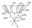
ここでより具体的に図22から29までを参照すると、本発明の実施態様による典型的位置評価アッセンブリ又は手段の一部である光学プローブ198がより詳細に示されている。図27に模式的に示されるように、光学プローブ198は、標的表面204に向けて投射光軸202に沿ってプローブ光線を投射するための距離プローブ光源200を含む。光学プローブ198はまた、プローブ光線が標的表面204によって反射されたならば、標的センサー光軸208に沿って移動するプローブ光線を検出するための距離プローブ標的センサー206を含む。 Referring now more specifically to FIGS. 22-29, there is shown in more detail an
距離プローブ光源200と距離プローブ標的センサー206とは、投射光軸202と標的センサー光軸208とが互いにある角度をなし、実質的に、標的表面204が、光活性化光源から、所定の標的対光活性化光源隔絶距離210だけ離れた時にのみ、標的表面204において相互に干渉し合うような構成、寸法、及び位置を有する。言い換えると、距離プローブ光源200と距離プローブ標的センサー206とは、標的表面204が、光活性化光源200から、所定の標的対光活性化光源隔絶距離210だけ離れた時、或いは、所定の範囲内にある時にのみ、距離プローブ光源200によって投射され、標的表面204によって反射されるプローブ光線を受容するか、或いは、検出することが可能となる構成、寸法、及び位置を有する。 The distance probe
従って、光学プローブ198は、光活性化光源が、所定の標的対光活性化光源隔絶距離210だけ標的表面204から離れた場合に、標的センサー光軸208と投射光軸202とが互いに角度を形成し、実質的に標的表面204上で相互に干渉し、それによって距離プローブ標的センサー206がプローブ光線を検出することを可能とするように構成される。 Thus, the
光学プローブ198は通常、プローブ光線が枠外センサー光軸に沿って移動する場合に、そのプローブ光線を検出するための、少なくとも1個の距離プローブ枠外センサーを含む。これらの図を通じて示される実施態様では、光学プローブ198は、距離プローブ近方センサー212と距離プローブ遠方センサー214の両方を含む。これらは、それぞれ、プローブ光線が、近方センサー光軸216及び遠方センサー光軸218に沿って移動する場合に、そのプローブ光線を検出するためのものである。 The
図28により具体的に描かれるように、距離プローブ光源200と距離プローブ遠方センサー214は、光活性化光源が、所定の遠方隔絶範囲において、ある遠方隔絶距離219だけ標的表面204から離れた場合、プローブ光線は、標的表面204によって反射されて遠方センサー光軸218に沿って移動するような構成、寸法、及び位置を有する。同様に、図29に示されるように、距離プローブ光源200と距離プローブ近方センサー212は、光活性化光源が、所定の近方隔絶範囲において、ある近方隔絶距離217だけ標的表面204から離れた場合、プローブ光線は、標的表面204によって反射されて近方センサー光軸216に沿って移動するような構成、寸法、及び位置を有する。 As illustrated more specifically in FIG. 28, the distance probe
近方及び遠方センサー212と214とは通常、所定の近方及び遠方隔絶範囲に一致する、所定の対応光学角度範囲216、218内から発せられる光線を検出する、或いは、そのような光線によって活性化されるように構成される。通常、近方、遠方、及び標的隔絶範囲は、相互に実質的に接触し、実質的に連続的動作隔絶範囲を形成する。 The near and
通常、距離プローブ光源200は、赤外スペクトラム内に位置する周波数を有するプローブ光線の発射を可能とする。従って、距離プローブの標的、近方、及び遠方センサー206、212、及び214は通常、赤外スペクトラム内の光線を検出したり、或いは、そのような光線によって活性化されるように適応する。赤外スペクトラムは、肌色の濃い患者について距離探査を行うのに特に有用である可能性がある。しかしながら、距離プローブ光源200は、本発明の範囲から逸脱することなく、他の周波数範囲内のプローブ光線を発射するのに用いることが可能であることを理解しなければならない。 Typically, the distance probe
通常、光学プローブ198はまた、標的表面204の上に配せられる標的位置に向けたプローブ光線の照準を可能とする、位置評価アッセンブリ又は手段に動作するように結合した、照準アッセンブリ又は手段を含む。通常、照準手段は、標的表面に向けて視覚的に焦点を結ぶための、視覚的照準光ビームを含む。照準光ビームは、適当なものであれば、任意の手段によって、例えば、図25に示す照準LED224によって形成されてもよい。 Typically, the
図22から26までにより具体的に描かれるように、光学プローブ198は通常光学プローブケーシングを含む。次に、この光学プローブケーシングは、距離プローブ光源200の少なくとも一部を保護的に収納するための光源腔226、距離プローブ標的センサー206の少なくとも一部を保護的に収納するための標的センサー腔228、距離プローブ近方センサー212の少なくとも一部を保護的に収納するための近方センサー腔230、及び、距離プローブ遠方センサー214の少なくとも一部を保護的に収納するための遠方センサー腔232を含む。 As depicted more specifically in FIGS. 22-26, the
光学プローブケーシングは通常、並列順序で、互いに角度を形成する関係において、距離プローブ光源200、距離プローブ近方センサー212、距離プローブ遠方センサー214、及び、距離プローブ標的センサー206を含む。通常、光学プローブケーシングは、ケーシング入力端234と、実質的にそれと向き合うケーシング出力端236を定める。 The optical probe casing typically includes a distance probe
光源腔226は、全体として長方形の形を有し、実質的にケーシング入力端234からケーシング出力端236まで光学プローブケーシングを貫いて延在する。光源腔226は通常、ケーシング出力端236に向かって先細りする実質的に円錐台形を有する。 The
通常、光学プローブ198は更に、光学プローブケーシングに対して投射光軸202の相対的方向の調節を可能とする、光源アラインメントアッセンブリ又は手段を含む。通常、距離プローブ標的センサー206、距離プローブ遠方センサー214、及び距離プローブ近方センサー212にはまた、実質的に同一の、或いはそれぞれ異なる角度調節手段が設けられる。 Typically, the
図25により具体的に描かれるように、光源アラインメントアッセンブリ又は手段は通常、光学プローブケーシングに距離プローブ光源200を搭載するための、プローブ光源搭載部品238を含む。更に、光源腔226は通常、ケーシング入力端234に実質的に隣接する光源搭載セクション240を有する。これは、光源搭載部品238を受容し、光源搭載セクション240における該部品の選択的運動を可能とするためのものである。通常、光源腔226は腔の長軸を定め、光源搭載セクション240は、その中に収められた光源搭載部品238が、実質的に弓状の調節軌跡242に沿って選択的移動することを可能とするような構成と寸法を有する。 As more specifically depicted in FIG. 25, the light source alignment assembly or means typically includes a probe light
図24により具体的に描かれるように、光源搭載部品238は通常、距離プローブ光源200を受容するための、実質的に円筒形の光源受容通路244、及び、一対の、実質的に放射方向に搭載部品を誘導するフランジ246を含む。光源搭載部品238は、一対の、互いに向き合い、実質的に平坦な搭載部品誘導面248(図24ではその内の一方だけが示される)を定める。搭載部品誘導面248の内の少なくとも一方には、それから実質的に外方に延在する対応する誘導舌250が設けられる。 As illustrated more specifically in FIG. 24, the light
図22、23、25、及び26により具体的に描かれるように、光学プローブケーシングは、一対の互いに向き合うプローブケーシング主壁252、253において、その間に延在するケーシング辺縁壁255によって互いに隔絶関係に維持される一対の主壁を定める。ケーシング主壁252、253は、対応するケーシング壁連結口251を貫いて延在する通例の連結部品、例えば、ネジ、ボルトなど(図示せず)を用いて、解除可能的に組み立てられるように適応される。 As specifically illustrated by FIGS. 22, 23, 25, and 26, the optical probe casing is isolated from each other by a pair of opposing probe casing
図25に描かれるように、ケーシング出力端236に近接して、ケーシング辺縁壁255には、光源出力口256及びケーシング標的口258が設けられる。これらの開口は、それぞれ、光源腔226及び標的センサー腔228と光学的に連通しながら、いずれもケーシング辺縁壁を貫通して延在する。同様に、ケーシング辺縁壁にはまた、それぞれ、近方センサー腔230及び遠方センサー腔232と光学的に連通しながら、該壁を貫通して延在する近方光学スロット260と遠方光学スロット262が設けられる。 As depicted in FIG. 25, in the vicinity of the
ケーシング主壁252、253の内の少なくとも一方、好ましくは両方に、対応する誘導舌250を、誘導を可能とするやり方で受容するための誘導溝254、254’が形成される。通常、ケーシング主壁253に形成される誘導溝254’は、ケーシング主壁252、253の分解を必要とすることなく対応する誘導舌250に接近できるように、該主壁を貫通して延在する。
通常、対応する誘導溝254’に挿入される誘導舌250には、その内部に形成される対応舌ノッチ264が設けられる。舌ノッチ264は、その中に、実質的に尖鋭な対象物の挿入を受容するように適応される。次に、実質的に尖鋭な対象物は、光学プローブケーシングに対する、投射光軸202、標的センサー光軸208、投射光軸202、近方センサー光軸216、及び/又は、遠方光軸218のアラインメント調節の間、誘導溝254、254’に沿って誘導舌250が滑走するのを補助するため使用されるように適応される。 Usually, the
光源アラインメントアッセンブリ又は手段は通常更に、アラインメントロック−アッセンブリ又は手段を含む。これは、プローブ光源搭載部品238を、それぞれの光源搭載セクション240に対して、それぞれのアラインメント関係に解除可能にロックするためのものである。アラインメントロック−アッセンブリ又は手段は通常、誘導溝254’に実質的に近接してケーシング主壁253に形成されるロック開口266を含む。アラインメントロック−アッセンブリ又は手段は通常また、対応するロック開口266にネジ溝を介して挿入が可能なロックネジ等(図示せず)を含む。 The light source alignment assembly or means typically further includes an alignment lock-assembly or means. This is for locking the probe light
各ロックネジは、対応する光源搭載セクション240における対応するプローブ光源搭載部品238の動きを機能的に阻止するために、対応する搭載部品誘導面248に摩擦的に接触するように適応する。 Each lock screw is adapted to frictionally contact the corresponding mounting
図10により具体的に描かれるように、位置評価アッセンブリ又は手段は通常、1組の意図的に配された光学プローブ198を含む。図10に示した光学プローブ198は、中央ヘッドセクション86にしか認められないけれども、通常、中央ヘッドセクション86と側方ヘッドセクション88にはそれぞれ、独立組の意図的に配された光学プローブ198が設けられる。これは、標的表面に対するそれぞれの位置を独立に評価することを可能にするためのものである。 As more specifically depicted in FIG. 10, the position assessment assembly or means typically includes a set of intentionally arranged
通常、光学プローブ198は、ケーシング冷却チャンネル156の中に配置される。しかしながら、光学プローブ198は、本発明の範囲から逸脱することなく、別の場所に配置することが可能であることを理解しなければならない。 Normally, the
更に、本発明の範囲から逸脱することなく、別のタイプの位置測定又は評価手段も使用が可能である。本発明の別の実施態様では(図示せず)、位置測定手段は、測定ビームを標的表面へ向けるための光源と、標的表面から反射された測定ビームの一部を受容するように配置された光検出器を含む。 Further, other types of position measurement or evaluation means can be used without departing from the scope of the present invention. In another embodiment of the invention (not shown), the position measuring means is arranged to receive a light source for directing the measurement beam to the target surface and a portion of the measurement beam reflected from the target surface. Includes a photodetector.
光源測定ビームの一部をモニター光検出器に向けて反射するために、ビームスプリッターが光源と標的表面の間に配置される。モニター光検出器は、反射ビームを受容し、ビームスプリッターの反射ビームの位置、従って、理想位置に対する光源の相対位置を表す出力信号を供給する。 A beam splitter is disposed between the light source and the target surface to reflect a portion of the source measurement beam toward the monitor photodetector. The monitor photodetector receives the reflected beam and provides an output signal representative of the position of the reflected beam of the beam splitter, and thus the relative position of the light source with respect to the ideal position.
一つの実施態様では、光検出器は、光源の理想の中心線と実際の中心線の間の偏倚を表すモニター出力信号を生成する。モニター出力信号はディスプレイ目的のために用いてもよい。モニター出力信号はまた、位置手段と共に用い、光源を、その実際位置から理想位置へと変位させ、そうすることによって光源の実際位置に関連する測定誤差を縮小するようにしてもよい。 In one embodiment, the photodetector generates a monitor output signal that represents the deviation between the ideal centerline of the light source and the actual centerline. The monitor output signal may be used for display purposes. The monitor output signal may also be used with position means to displace the light source from its actual position to the ideal position, thereby reducing the measurement error associated with the actual position of the light source.
選択的に、装置10には更に、最適ヘッド表面対標的表面動作距離128の値及び/又は最適電力密度値及び/又は他の動作パラメータに関する最適値に影響を及ぼす可能性のある、環境及び/又は標的組織パラメータを検出するための検出手段を設けてもよい。例えば、装置10には更に選択的に、温度センサー、ヒフ色素沈着又は色相センサー、皮膚厚センサー等を設けてもよい。 Optionally, the
装置10には更に選択的に、所定の光誘起作用を実現するために選択された操作パラメータの最適調節を可能とするための手段を設けてもよい。選択操作パラメータの最適調節を可能にするための手段は通常、選択操作パラメータの全体的又は局所的調節を可能とする。 The
光による放射療法は、いくつかの臨床状況で効果的ではあるが、この療法の病理生物学的根拠は少なくとも部分的には誤解されたままである。電磁波スペクトラムの可視域(380-700 nm(ナノメートル))、及び赤外域(700-1000 nm)両領域の波長が、その光化学的及び光物理的性質においては大きな差があるにも拘わらず、この療法では効果的で、多くの場合類似の臨床成績を挙げている。 Although radiation therapy with light is effective in some clinical situations, the pathobiological basis of this therapy remains at least partially misunderstood. Despite the large differences in the photochemical and photophysical properties of the wavelengths in both the visible (380-700 nm (nanometer)) and infrared (700-1000 nm) regions of the electromagnetic spectrum, This therapy is effective and often has similar clinical outcomes.
生物組織に対するレーザー光刺激の大きさは、光の波長の他に、少なくとも4個から成る1組のパラメータに依存することが明らかにされている。すなわち、1.光強度閾値(照射、又はl0)、2.ビーム断面(スポットサイズ)、3.合計照射時間(△ttot)、及び4.エネルギー投与量(フルエンス)である。変調のための関連パラメータは下式に従って相互に関連付けられる。
フルエンス=lstim × △ttot
式中lstim>l0である。In addition to the wavelength of light, the magnitude of laser light stimulation on biological tissue has been shown to depend on a set of at least four parameters. That is, 1. light intensity threshold (irradiation or l0 ), 2. beam cross section (spot size), 3. total irradiation time (Δttot ), and 4. energy dose (fluence). The relevant parameters for the modulation are related to each other according to the following equation:
Fluence = lstim × △ ttot
Where lstim> l0 .
生物組織では、閾値l0よりも低い光強度は、照射時間△ttotが長くとも変調作用を生じない。フルエンス、及び、照射とも呼ばれるパワー密度は、非定常パワー密度を時間の関数として用いることが許されることから分かるように、相互に独立する。上の方程式におけるフルエンスの作用範囲は、様々なレベルのエネルギー密度における様々なモードの細胞反応を示すArndt-Shultz曲線によって示される(57)。In biological tissues, the light intensity lower than the threshold value l0 does not cause a modulation effect even if the irradiation time Δttot is long. The power density, also called fluence and illumination, is independent of each other, as can be seen from the fact that unsteady power density is allowed to be used as a function of time. The range of action of the fluence in the above equation is shown by the Arndt-Shultz curve showing different modes of cellular response at different levels of energy density (57).
上述のパラメータの他に、周期的時間変動照射ではビーム反復頻度も、生物組織の活性化/抑制に対して長期的影響を及ぼす。パルス周波数が直接作用を有することは、マクロファージにおいて更に追加のCa2+が摂取されたこと(58)、及び、適当なパルス持続時間及び反復周波数を有するパルス型半導体レーザーによる照射後、げっ歯類脾臓細胞の化学発光が強調されたこと(59)が観察されるなど実験側から支持されている。更に、臨床側方からも支持されている(15)。In addition to the parameters described above, the beam repetition frequency also has a long-term effect on the activation / suppression of biological tissue in periodic time-varying irradiation. The fact that the pulse frequency has a direct effect is that additional Ca2+ was ingested in macrophages (58), and rodents after irradiation with a pulsed semiconductor laser with appropriate pulse duration and repetition frequency. The fact that chemiluminescence of spleen cells is emphasized (59) is observed, and this is supported by the experimental side. Furthermore, it is supported from the clinical side (15).
皮膚科学におけるレーザー応用の圧倒的多数が、レーザー誘発による加熱を用いる。光活性化/抑制とは対照的に、加熱は、何ら特別のフォトン熱エネルギーを要しない。「選択的輻射熱細胞分解」は更に高レベルの熱を用いる。この方法は、その定式化(56)以来15年に渡って皮膚科学におけるレーザーの応用範囲を変えてきた。この用語は、選択的に吸収される光パルスによって、顕微鏡的な、特定の組織標的に対し、部位特異的に、熱によって引き起こされる傷害を記述するために創り出された(55,56)。このように限局したネルギーは、周囲の皮膚に対しては損傷を与えることなく、標的(すなわち、血管ではオキシヘモグロビン、色素細胞ではメラニン)を凝固させる。 The overwhelming majority of laser applications in dermatology use laser-induced heating. In contrast to photoactivation / suppression, heating does not require any special photon thermal energy. “Selective radiant heat cytolysis” uses higher levels of heat. This method has changed the scope of laser applications in dermatology for 15 years since its formulation (56). The term was created to describe heat-induced injuries site-specifically to specific tissue targets microscopically with selectively absorbed light pulses (55,56). This localized energy coagulates the target (ie oxyhemoglobin in blood vessels and melanin in pigment cells) without damaging the surrounding skin.
従って、暴露持続時間及び緩和時間は、十分に確立された選択的輻射熱細胞分解概念では比較的重要である。いわゆる熱緩和時間(TRT)、すなわち、小型の標的構造の明確な冷却に必要な時間は、選択的輻射熱細胞分解では主要な役割を演じる。熱伝導が皮膚の顕微鏡構造の冷却を支配する。しかしながら、顕微鏡的スケールの放射冷却実験を更に重ねることが求められている(55)。レーザー暴露がTRT未満の場合、最大の熱封じ込めが起こる。 Thus, exposure duration and relaxation time are relatively important in a well-established selective radiant heat cytolysis concept. The so-called thermal relaxation time (TRT), ie the time required for clear cooling of small target structures, plays a major role in selective radiant heat cytolysis. Heat conduction dominates the cooling of the skin microstructure. However, further microscopic-scale radiation cooling experiments are required (55). Maximum heat containment occurs when laser exposure is below TRT.
光化学反応の量子的成果は、光エネルギーがシステムによって吸収された場合に光化学が起こる確率である。従って、システムの真の光化学的感度は二つの確率の積、すなわち、任意の波長の光が吸収される確率、及び、吸収された光が化学的変化をもたらす確率の積である。従って、ある任意の波長の光について治療効果が認められたならば、臨床効果を実現するための、最適エネルギーパラメータと最適治療回数を決定しなければならない。 The quantum outcome of a photochemical reaction is the probability that photochemistry will occur when light energy is absorbed by the system. Thus, the true photochemical sensitivity of the system is the product of two probabilities: the probability that light of any wavelength will be absorbed and the probability that the absorbed light will cause a chemical change. Therefore, if a therapeutic effect is observed for light of an arbitrary wavelength, the optimum energy parameter and the optimum number of treatments for realizing the clinical effect must be determined.
酵素の光活性化は、光生物学においてもっとも急速に成長している分野の一つであり、この主題についていくつかの総説が既に発表されている(7-9)。酵素は触媒である。原理的には、一つのフォトンが一つの酵素分子を活性化することが可能であり、その活性化酵素分子は次に、数千もの数多くの基質分子を処理することが可能である。酵素の活性化は、光による生物反応を起動するための巨大な増幅係数となる。この驚くべき増幅性が、なぜ低レベルレーザー放射療法が効果的であるのか、その理由を説明するものであるのかも知れない。一つのフォトンの作用が生物学的に増幅可能であるとするならば、生理的作用を生ずるのにそれほど多くのフォトンは必要とされない。ある任意の酵素を刺激し、好ましい治療効果をもたらすように光のパラメータを最適化し、決定しなければならない。酵素を光活性化又は抑制するために、直接法及び間接法を含めいくつかの方法が提案されている。 Enzyme photoactivation is one of the fastest growing fields in photobiology, and several reviews have already been published on this subject (7-9). Enzymes are catalysts. In principle, one photon can activate one enzyme molecule, which in turn can process thousands of substrate molecules. The activation of the enzyme becomes a huge amplification factor for starting a biological reaction by light. This surprising amplification may explain why low-level laser radiation therapy is effective. Given that the action of a single photon is biologically amplifiable, not many photons are required to produce a physiological effect. Light parameters must be optimized and determined to stimulate any enzyme and provide a favorable therapeutic effect. Several methods have been proposed to photoactivate or inhibit the enzyme, including direct and indirect methods.
1. 基質を活性化(生産)する
例えば、細胞がUV放射に暴露されると、DNAに起こった光化学的傷害は、その基質、すなわち、損傷DNAの存在によって活性化された1組のDNA修復酵素によって修復される。1. Activating (producing) a substrate For example, when a cell is exposed to UV radiation, photochemical damage that occurs to DNA is a set of DNA repairs activated by the presence of that substrate, that is, damaged DNA. Repaired by enzymes.
2. 酵素−基質複合体を活性化する
UV放射光生物学から取られた別の例では、光反応性酵素(DNAフォトリアーゼ)は、その基質として、一つのタイプのDNA損傷、すなわち、シクロブタン型ピリミジン二量体を認識し、暗黒中でこの二量体と結合する。この酵素−基質複合体が可視光に暴露されると活性化が起こり、光のエネルギーは酵素によって二量体を分割するのに用いられ、修復DNAをもたらす。2. Activate the enzyme-substrate complex
In another example taken from UV radiation photobiology, photoreactive enzyme (DNA photolyase) recognizes one type of DNA damage as its substrate, namely cyclobutane pyrimidine dimer, in the dark Binds to this dimer. When this enzyme-substrate complex is exposed to visible light, activation occurs and the light energy is used by the enzyme to split the dimer, resulting in repair DNA.
3. 酵素を直接活性化する
これは一般に、酵素分子そのものにおいて、或いは、酵素に付属の光発色性抑制因子において立体配置変化を誘発することによって確かめられる。このような機構のそれぞれについて多くの例がある(7-9)。3. Direct activation of the enzyme This is generally confirmed by inducing a conformational change in the enzyme molecule itself or in the photochromic inhibitor associated with the enzyme. There are many examples of each of these mechanisms (7-9).
4. 酵素の合成を誘発する
これは遺伝子活性化によって起こることがある。例えば、細菌をUV照射すると、DNA修復酵素の全グループが誘発される。これら誘発酵素の内のあるものは、誘発前には検出濃度として存在していなかったのであるが、一方、別のある酵素は少量存在していたが、UV照射によって更に大量に誘発される。633 nmにおけるレーザー放射は、1型及び2型プロコラーゲンmRNAレベルを増強することによって、皮膚外傷におけるコラーゲン合成を促進することが明らかにされている(10)。4. Induces enzyme synthesis This can be caused by gene activation. For example, irradiating bacteria with UV induces an entire group of DNA repair enzymes. Some of these triggering enzymes were not present as detection concentrations prior to triggering, while some other enzymes were present in small quantities but are triggered in larger quantities by UV irradiation. Laser radiation at 633 nm has been shown to promote collagen synthesis in skin trauma by enhancing
以上、光による酵素の活性化はいくつかの異なる機構によって起こり得る。前述の最初の二つの機構、すなわち、放射起動による基質の生産、及び酵素−基質複合体への照射は生物反応の増幅をもたらさない。なぜなら、各光化学事象が起こるには吸収された一つのフォトンが必要だからである。そのために、これらの事象には高レベルの放射が必要となる。 Thus, enzyme activation by light can occur by several different mechanisms. The first two mechanisms mentioned above, namely the production of the substrate by radiation activation and the irradiation of the enzyme-substrate complex, do not lead to an amplification of the biological reaction. This is because each photochemical event requires one absorbed photon. Therefore, these events require high levels of radiation.
最後の二つの機構、すなわち、酵素の直接的活性化及び酵素合成の誘発は、吸収されたフォトンの数よりも多くの化学的変化をもたらし、前述の二つの過程よりも低レベルの放射によって実現される。従って、上記最後の二つの酵素活性化機構は、スペクトラム可視領域の低レベルレーザー放射療法において光生物学的基盤の強力な候補となる。 The last two mechanisms, namely the direct activation of the enzyme and the induction of enzyme synthesis, result in more chemical changes than the number of absorbed photons and are achieved by lower levels of radiation than the previous two processes. Is done. Thus, the last two enzyme activation mechanisms are strong candidates for photobiological infrastructure in low-level laser radiation therapy in the visible spectrum region.
赤外領域における放射吸収は、分子回転(ある軸周囲における分子全体の回転)と分子振動(結合の伸長又は湾曲で、これは、各分子に対する原子核の変位を招くが核の平衡位置には影響を及ぼさない)はもたらす。従って、赤外放射は、反応速度は加熱によって増すかも知れないが、分子中に化学的変化をもたらすとは考えられない。 Radiation absorption in the infrared region is molecular rotation (rotation of the whole molecule around a certain axis) and molecular vibration (bond elongation or curvature), which causes nuclear displacement for each molecule, but does not affect the equilibrium position of the nucleus. Will not bring). Thus, infrared radiation is not believed to cause chemical changes in the molecule, although the reaction rate may be increased by heating.
もしも低レベルの可視光療法の生物学的作用が光化学によるもの(酵素の光活性化と考えられる)であり、赤外放射の生物学的作用が分子回転と振動によるものであるとするならば、光放射療法が、可視光放射を用いた場合でも、赤外放射を用いた場合でも、どうして類似の臨床反応を生成するのであろうか?例えば、Abergelと共同研究者達(12,13)は、培養線維芽細胞に対して633 nmで照射しても、904 nmで照射してもコラーゲンの合成を促進することを認めた。別の実験において、633 nmの放射でも(14)、1060 nmの放射でも(15)、共に慢性関節リウマチの痛みを緩和するのに有効であった。 If the biological effects of low-level visible light therapy are due to photochemistry (possibly photoactivation of the enzyme) and the biological effects of infrared radiation are due to molecular rotation and vibration Why does light radiation therapy produce a similar clinical response whether using visible light radiation or infrared radiation? For example, Abergel and coworkers (12, 13) have found that cultured fibroblasts can stimulate collagen synthesis when irradiated at 633 nm or 904 nm. In another experiment, both 633 nm radiation (14) and 1060 nm radiation (15) were both effective in relieving pain in rheumatoid arthritis.
633 nmにおける低レベル放射の生体刺激作用を説明するために、Karu(1)は、光受容器による光の吸収から始まる、一連の分子事象を提案した。この一連の分子事象は、シグナル変換及び増幅を招き、最終的には光反応をもたらす。Karuのモデルでは、光は、呼吸鎖部品(すなわち、フラビンデヒドロゲナーゼ、シトクローム、及びシトクロームオキシダーゼ)によって吸収され、これが呼吸鎖の活性化とNASプールの酸化を招き、これがミトコンドリアと細胞質の両方の酸化還元状態の変化をもたらす。これが次に、膜の透過性/輸送に作用を及ぼし、Na’/H’比が変化し、Na’/K’-ATPアーゼ活性が増加し、Ca++フラックスに作用を及ぼす。Ca++フラックスは、環状ヌクレオチドのレベルに作用を及ぼし、これが、DNA及びRNA合成を変え、細胞増殖を変調する(すなわち、生体刺激)。 To explain the biostimulatory effect of low-level radiation at 633 nm, Karu (1) proposed a series of molecular events starting with the absorption of light by photoreceptors. This series of molecular events leads to signal conversion and amplification, ultimately resulting in a photoreaction. In the Karu model, light is absorbed by respiratory chain components (ie, flavin dehydrogenase, cytochrome, and cytochrome oxidase), which leads to activation of the respiratory chain and oxidation of the NAS pool, which is a redox of both mitochondria and cytoplasm. Bring about a change of state. This in turn affects membrane permeability / transport, changes the Na '/ H' ratio, increases Na '/ K'-ATPase activity, and affects Ca ++ flux. Ca ++ flux affects the level of cyclic nucleotides, which alters DNA and RNA synthesis and modulates cell proliferation (ie, biostimulation).
このことはまた、なぜ904 nmの放射が、633 nmの放射によって生じるものと同じ生物作用を生むのかという理由の説明を示唆する。Krausのモデルでは、633 nmの放射は、恐らくミトコンドリアの酵素を光活性化することによって、光反応に至る縦列の分子事象を起動する。904 nmの放射も同じ最終反応を生ずるが、生体刺激に至る全縦列分子事象の約半分過程の膜レベル(恐らくCa++チャンネルに対する光物理作用を通じて)で反応を起動する。 This also suggests an explanation of why 904 nm radiation produces the same biological effects as produced by 633 nm radiation. In the Kraus model, 633 nm radiation triggers tandem molecular events leading to photoreaction, possibly by photoactivating mitochondrial enzymes. Radiation at 904 nm results in the same final response, but triggers the reaction at the membrane level (possibly through photophysical action on the Ca ++ channel) about halfway through all tandem molecular events leading to biological stimulation.
多くのシグナル伝達系においてカルシウムイオンは細胞内メッセンジャーとなる。Ca++の細胞内レベルは低く維持されるのが好都合である。なぜならリン酸エステルが優勢になり、リン酸カルシウムが極めて溶けにくくなるからである。興奮していない細胞におけるCa++の細胞質ゾルレベルは、細胞外濃度よりも数桁低い。従って、細胞質ゾルのCa++濃度は、原形質膜又は細胞内膜のカルシウムチャンネルを一過性に開くことによって急激に上昇させられ、シグナル伝達を実行することが可能となる(16-23)。 In many signal transduction systems, calcium ions are intracellular messengers. Conveniently, intracellular levels of Ca ++ are kept low. This is because phosphate esters become dominant and calcium phosphates are extremely difficult to dissolve. The cytosolic level of Ca ++ in unexcited cells is orders of magnitude lower than the extracellular concentration. Thus, the cytosolic Ca ++ concentration is rapidly increased by transiently opening plasma channels or intracellular membrane calcium channels, allowing signal transduction to be performed (16-23).
最近の論文で、Karu(1)は下記の発言をしている。すなわち、「レーザーの生体刺激の大きさは、照射の瞬間における細胞の生理的状態に依存する。」この発言は、作用が必ずしもいつも検出可能であるとは限らないことと同時に、文献に報告される結果の変動性をも説明する。 In a recent paper, Karu (1) made the following statement: That is, “The magnitude of the laser biostimulation depends on the physiological state of the cell at the moment of irradiation.” This statement is reported in the literature, as well as the effect is not always detectable. It also explains the variability of the results.
例えば、照射は、HeLaの成長の遅い下部集団の増殖を加速することが明らかにされている。医学では、レーザー治療は、重大な損傷(例えば、栄養障害性潰瘍)の場合に効くようであり、正常に再生する外傷に対する光の作用は(仮にあったとしても)ごく僅かのようである。光は、照射時に細胞の成長が低下している場合にのみ細胞増殖を促進する。従って、細胞が完全に機能的である場合には、レーザー放射が促進するものは何もなく、治療的効果は観察されない。患者は、彼等が日々の食事で既に十分なビタミン補給を受けている場合には、ビタミン療法の効果を示さないというのと同様の例である。 For example, irradiation has been shown to accelerate the growth of a slow growing subpopulation of HeLa. In medicine, laser treatment appears to work in the case of serious injury (eg, dystrophic ulcers) and the effect of light on normal regenerating trauma appears to be negligible (if any). Light promotes cell proliferation only when cell growth is reduced upon irradiation. Thus, if the cells are fully functional, nothing is promoted by laser radiation and no therapeutic effect is observed. Patients are similar to the fact that they do not show the effects of vitamin therapy if they are already receiving sufficient vitamin supplements in their daily diet.
生体組織及び細胞と、放射との間の相互作用についてはこれまでにも広範に調べられている。このような研究の非限定的例が文献番号1-60、A1-A7、及びB1-B7に見出される。 The interaction between living tissue and cells and radiation has been extensively investigated. Non-limiting examples of such studies are found in literature numbers 1-60, A1-A7, and B1-B7.
下記の説明本文では、ここに請求される本発明が所望の効果を実現する原因となる機構のいくつかが提案される。しかしながら、本発明のいくつかの実施態様は、別々の機構を通じて所望の効果を実現する。従って、ここに提案される機構は、そのような機構について請求することをしない付属の請求項の範囲を限定するものと解釈してはならない。 In the description text that follows, some of the mechanisms by which the claimed invention achieves the desired effects are proposed. However, some embodiments of the present invention achieve the desired effect through separate mechanisms. Accordingly, the mechanisms proposed herein should not be construed as limiting the scope of the appended claims not claiming such mechanisms.
第1面では、ここに請求される本発明は、哺乳類組織、例えば、哺乳類皮膚組織の治療法において、複数の放射パルスを含むパルス列を定める放射によって組織を照射する方法を含む。放射は、約400ナノメートルから約1500ナノメートルの波長を有し、パルスはそれぞれ約1フェムト秒から約1時間の持続を有し、パルスは互いに、約1マイクロ秒から約10秒のパルス間隔で隔てられ、かつ、組織における各パルスの電力密度は、約0.1 mW/cm2から約10 W/cm2である。放射を記述するパラメータは全て互いに独立に調整が可能であるか、組織内で協調作用をもたらすような組み合わせで調整される。In a first aspect, the presently claimed invention includes a method of irradiating tissue with radiation defining a pulse train comprising a plurality of radiation pulses in a method for treating mammalian tissue, eg, mammalian skin tissue. The radiation has a wavelength of about 400 nanometers to about 1500 nanometers, each pulse has a duration of about 1 femtosecond to about 1 hour, and the pulses have a pulse interval of about 1 microsecond to about 10 seconds with each other. And the power density of each pulse in the tissue is from about 0.1 mW / cm2 to about 10 W / cm2 . All parameters describing radiation can be adjusted independently of each other or in a combination that provides a cooperative action within the tissue.
各種パルスパラメータの正確な値は、求める作用に依存する。求める比較的特異な値及び作用の例を下記に示す。 The exact values of the various pulse parameters depend on the desired action. Examples of relatively specific values and actions to be obtained are shown below.
これらの例の内の一つでは、パルスはそれぞれ約100マイクロ秒から約100ミリ秒の持続を有する。極めて特異な実例では、パルスはそれぞれ約250マイクロ秒から約1ミリ秒の持続を有する。 In one of these examples, each pulse has a duration of about 100 microseconds to about 100 milliseconds. In a very specific example, each pulse has a duration of about 250 microseconds to about 1 millisecond.
これらの例の内の更に別のものでは、パルス間間隔は、約10マイクロ秒から約10ミリ秒である。極めて特異な実例では、パルス間隔は約100マイクロ秒から約500マイクロ秒である。 In yet another of these examples, the interpulse interval is from about 10 microseconds to about 10 milliseconds. In a very specific example, the pulse interval is from about 100 microseconds to about 500 microseconds.
パルス持続時間及びパルス間間隔は、互いに別々に考えてもよいが、これら二つのパラメータに関連する協調作用を考慮することも本発明の範囲内にある。 Although the pulse duration and the inter-pulse interval may be considered separately from each other, it is within the scope of the present invention to take into account the cooperative action associated with these two parameters.
例えば、パルス間隔で除したパルス持続時間の比は任意の適当な値を取る。特異な実例では、パルス間隔で除したパルス持続時間の比は、約0.1から約10の間隔内にある。極めて特異な実例では、パルス間隔で除したパルス持続時間の比は、約0.5から約2の間隔内にある。この最後の間隔において、ただしそれに限定するものではないが、約1である、パルス間隔で除したパルス持続時間の比は、技術的に実現可能である一方で、皮膚において所望の効果をもたらすことが判明した。 For example, the ratio of the pulse duration divided by the pulse interval takes any suitable value. In a specific example, the ratio of pulse duration divided by pulse interval is within an interval of about 0.1 to about 10. In a very specific example, the ratio of pulse duration divided by pulse interval is in the interval of about 0.5 to about 2. At this last interval, but not limited to it, a ratio of pulse duration divided by pulse interval of about 1 is technically feasible while providing the desired effect on the skin. There was found.
組織における各パルスの適当な電力密度の特異的例として、約30 mW/cm2から100 mW/cm2の間隔の中に含まれる電力密度がある。A specific example of a suitable power density for each pulse in the tissue is a power density contained within an interval of about 30 mW / cm2 to 100 mW / cm2 .
特異的実例では、方法は、複数のパルス列において、各パルス列が複数の放射パルスを含むパルス列を定める放射によって組織を照射することを含む。例えば、各パルス列は約2から100個のパルスを含む。複数のパルス列は互いに、その間にはパルスが生産されないパルス列間隔によって隔てられ、列間間隔は約1マイクロ秒から約1秒続く。 In a specific example, the method includes irradiating the tissue with radiation defining a pulse train, wherein each pulse train includes a plurality of radiation pulses in the plurality of pulse trains. For example, each pulse train includes approximately 2 to 100 pulses. The plurality of pulse trains are separated from each other by a pulse train interval between which no pulses are produced, and the inter-train interval lasts from about 1 microsecond to about 1 second.
用語「パルス」は広く解釈しなければならない。例えば、パルスは、仮令それが本発明のいくつかの実施態様において使用に好適なパルスの例であったとしても、列間間隔において電力密度が全く欠如した実質的に均一な電力密度のものである必要はない。 The term “pulse” should be interpreted broadly. For example, the pulses are of a substantially uniform power density that lacks any power density in the inter-column spacing, even if it is an example of a pulse that is suitable for use in some embodiments of the present invention. There is no need.
実際、各パルスは時間進化を表し、それが、何らかの適当な時間進化を有する複数のパルスを生み出すものにおいてもよい。また、列間間隔では、電力密度は、各パルス内における電力密度よりも実質的に小さくなるが、必ずしもゼロではない。列間間隔におけるこのような電力密度の例は後述する。 In fact, each pulse represents a time evolution, which may produce multiple pulses with some suitable time evolution. Also, at the inter-column spacing, the power density is substantially smaller than the power density within each pulse, but not necessarily zero. An example of such power density in the inter-column spacing will be described later.
非限定的な特異実例では、列間間隔は約500マイクロ秒から約2.25ミリ秒続き、各パルス列は4から10個のパルスを含む。列間間隔のパルス間間隔に対する比は、約2から約10であり、ある極めて特異な実例では、列間間隔のパルス間間隔に対する比は約3である。 In a non-limiting specific example, the interval between trains lasts from about 500 microseconds to about 2.25 milliseconds, and each pulse train contains 4 to 10 pulses. The ratio of inter-row spacing to inter-pulse spacing is about 2 to about 10, and in one very specific example, the ratio of inter-row spacing to inter-pulse spacing is about 3.
より詳細に後述するように、哺乳類組織を治療するための前記方法は、他に応用がある中で、哺乳類皮膚組織において所望の作用を生み出す点に応用が認められる。例えば、放射パワー密度時間プロフィールによって、哺乳類皮膚組織に所定の生理的変化が引き起こされる。 As described in more detail below, the method for treating mammalian tissue finds application in producing a desired effect in mammalian skin tissue, among other applications. For example, radiant power density time profiles cause certain physiological changes in mammalian skin tissue.
この特異的例の背景において、皮膚をパルス治療することが効果的である、すなわち、治療の全期間に渡って光源をエネルギー賦活することなく、むしろパルス照射して、パルスとパルスの間で、パルス列とパルス列の間で皮膚に休む時間を残すことの方が貴重であることが判明した。更に、所定の数の光パルスを既に発射した後では、しばしばより長い時間パルス列を止めることが必要であることが判明した。 In the context of this specific example, it is effective to pulse the skin, i.e., without activating the light source for the entire duration of the treatment, but rather pulsing, between pulses, It has been found that it is more valuable to leave time for resting on the skin between pulse trains. Furthermore, it has been found that it is often necessary to stop the pulse train for a longer time after already firing a predetermined number of light pulses.
一つの例では、放射は、所定の反復使用率に従う発光ダイオード(LED)を用いて行う。もちろん、所定の反復使用率を必要としないLEDを用いるならば、照射に関する多くの制限が取り除かれる。 In one example, the emission is performed using light emitting diodes (LEDs) according to a predetermined repeated use rate. Of course, many limitations on illumination are removed if LEDs are used that do not require a predetermined repetition rate.
加えて、所望の生理作用、すなわち、コラーゲン生産の増加を求める特異的例では、パルス状放射、例えば、前述のパルス状放射が有利であることが判明している。このようなパルス状放射の有効作用は他の多くの状況でも存在する。 In addition, in the specific case of seeking a desired physiological effect, i.e. an increase in collagen production, it has been found that pulsed radiation, for example the aforementioned pulsed radiation, is advantageous. The effective action of such pulsed radiation exists in many other situations.
更に具体的には、コラーゲン生産の増加に関連して言うと、暴露持続時間(「オン時間」)は比較的精密に監視される因子ではあるが、本発明の継続パルスの部品は、パルス緩和時間、すなわちパルス間隔時間(「オフ時間」)であることが分かっている。より短いパルス間隔時間の方が、代謝経路を改善しより健康な皮膚細胞をもたらすようである。従って、パルス列の中のパルスの数が所定されている以上、いくつかの組織では、軽く皮膚を休息させるためにダウン時間を提供する方が有利である。 More specifically, in relation to increased collagen production, although the duration of exposure (“on time”) is a relatively closely monitored factor, the continuous pulse component of the present invention provides pulse relaxation. It has been found to be time, ie, pulse interval time (“off time”). Shorter pulse interval times appear to improve metabolic pathways and result in healthier skin cells. Thus, as long as the number of pulses in the pulse train is predetermined, in some tissues it is advantageous to provide downtime to lightly rest the skin.
標的反応の選択性は、他の全ての定められたパラメータ(フルエンス、照射、治療時間、波長、スポットサイズ、動作距離等)が定常に維持されると仮定した場合、適当なパルス持続時間を選択するだけでなく、適当なパルス間間隔を選ぶことによって可能となる。ある特異的で非限定的な実例では、反応が求められる標的は発色団を含むが、別の標的も本発明の範囲内にある。 Target reaction selectivity selects the appropriate pulse duration, assuming that all other defined parameters (fluence, irradiation, treatment time, wavelength, spot size, working distance, etc.) are kept constant. This is possible by selecting an appropriate inter-pulse interval. In one specific, non-limiting example, the target for which a reaction is sought includes a chromophore, although other targets are within the scope of the present invention.
コラーゲン生産の増加に関連して言うと、パルス列は通常、実質的に等しいパルス持続時間を有し、実質的に等しいパルス間隔で隔てられた3個を上回る数のパルスを含む。パルス間隔においては組織内部にパワーは供給されない。各パルス列は、後続のパルス列から、列間間隔だけ隔てられる。 In connection with increased collagen production, pulse trains typically have a substantially equal pulse duration and comprise more than three pulses separated by substantially equal pulse intervals. No power is supplied inside the tissue during the pulse interval. Each pulse train is separated from the subsequent pulse train by an inter-row spacing.
より具体的には、ただし非限定的であるが、100-500 μsec間隔で隔てられたパルス列による250-1000 μsec(マイクロ秒)の3個以上のパルスを用いることは興味あることが判明した。細胞レベルでも分子レベルでも、使用されるLEDの反復使用率と生理的パラメータによって窺われるように、適当な持続のパルス列間隔は、パルス列を分離するのに用いられる。 More specifically, but not exclusively, it has proved interesting to use three or more pulses of 250-1000 μsec (microseconds) with a pulse train separated by 100-500 μsec intervals. Appropriate sustained pulse train intervals are used to separate the pulse trains, as dictated by the repeated usage and physiological parameters of the LEDs used, both at the cellular and molecular level.
本発明の多くの実施態様では、パルス持続時間、パルス間隔、各パルス列におけるパルスの数、及び、列間間隔は、各処置において実質的に定常であるが、これらのパラメータが全体治療に渡って定常ではない治療を実行することも本発明の範囲内にある。 In many embodiments of the invention, the pulse duration, the pulse interval, the number of pulses in each pulse train, and the interval between trains are substantially constant in each treatment, but these parameters are consistent throughout the entire treatment. It is also within the scope of the present invention to perform a non-stationary treatment.
あるセッションにおいて与えられるパルスの数は、多くのパラメータ、例えば、所望のパワー密度、使用するLED又はその他の光源によって発射されるエネルギー密度、波長、及び、スポットサイズに依存する。当業者には明らかとなるように、パルス列毎のパルスの数は可変であり、求める正確な作用に依存する。 The number of pulses given in a session depends on many parameters, such as the desired power density, the energy density emitted by the LED or other light source used, the wavelength, and the spot size. As will be apparent to those skilled in the art, the number of pulses per pulse train is variable and depends on the exact action desired.
前述のパルス状放射に類似したパルス状放射も、コラーゲン生産と無関係の他の皮膚病態を治療するのに使用が可能であることが見出されている。例えば、光阻害によってケロイドを治療したり、光活性化によって萎縮性瘢痕を治療することは可能であるようである。更に、提案の方法によって、にきび、湿疹、乾癬、白斑、酒さ、毛髪再生、外因性色素、皮膚黒色症、ある種の付属腫瘍、及び皮膚の色素過剰を治療することが可能であると考えられている。従って、前述の皮膚照射は、多くの皮膚科学病態にとって有用である。これらの治療を動かす、提案された非限定的機構は皮膚細胞活動の変調を含む。 It has been found that pulsed radiation similar to the aforementioned pulsed radiation can also be used to treat other skin conditions unrelated to collagen production. For example, it seems possible to treat keloids by photoinhibition or to treat atrophic scars by photoactivation. In addition, the proposed method may treat acne, eczema, psoriasis, vitiligo, rosacea, hair regeneration, exogenous pigment, skin melanosis, certain accessory tumors, and hyperpigmentation of the skin. It has been. Thus, the aforementioned skin irradiation is useful for many dermatological conditions. Proposed non-limiting mechanisms that drive these therapies include modulation of skin cell activity.
加えて、適当なパルス及び放射パラメータによって定められるパルス状放射の使用は、連続モード刺激によってもたらされるコラーゲン生産よりも実質的大きなコラーゲン生産の刺激を実現する。この作用をもたらすと考えられる、提案された、非限定的、非拘束的機構は、細胞疲労の緩和を含み、皮膚線維芽細胞の最適刺激ばかりでなく、コラゲナーゼの抑制も実現する。 In addition, the use of pulsed radiation defined by the appropriate pulse and radiation parameters achieves a stimulation of collagen production that is substantially greater than that produced by continuous mode stimulation. Proposed, non-limiting, non-restrictive mechanisms that are thought to bring about this effect include mitigation of cell fatigue and achieve not only optimal stimulation of dermal fibroblasts, but also inhibition of collagenase.
哺乳類皮膚組織を治療するための前述の方法、及びその方法から得られる結果もまた、哺乳類組織の生理を変える方法を示唆する。その方法は、組織を、適当な放射パワー密度プロフィールを定める放射によって照射することを含む。放射パワー密度プロフィールは、適当なものであれば、どのようなパワー密度時間プロフィールにおいてもよく、例えば、ただし非限定的であるが、複数のパルス列を含み、各パルス列は複数の放射パルスにおいて、所定のパルス幅を有し、パルス間間隔によって互いに隔てられ、パルス列は互いに列間間隔によって隔てられ、列間間隔は実質的にパルス間間隔よりも大きい、そのようなパルス列を含むパワー密度時間プロフィールである。 The aforementioned methods for treating mammalian skin tissue, and the results obtained from that method, also suggest ways to alter the physiology of mammalian tissue. The method includes irradiating the tissue with radiation that defines an appropriate radiation power density profile. The radiation power density profile may be any suitable power density time profile, for example, but not limited to, including a plurality of pulse trains, each pulse train being a predetermined number of radiation pulses. A power density time profile including such a pulse train, wherein the pulse trains are separated from each other by an inter-pulse spacing, the pulse trains are separated from each other by an inter-row spacing, and the inter-row spacing is substantially greater than the inter-pulse spacing. is there.
列間間隔の、パルス間間隔に対する比、及び各パルス列におけるパルスの数に関する適当な値の例は既に述べた。 Examples of suitable values for the ratio of inter-spacing to inter-pulse spacing and the number of pulses in each pulse train have already been described.
ある実例では、各パルス時において組織内に生ずる放射の最小パワー密度は、各パルス間隔中に組織内に生ずる放射の最大パワー密度の少なくとも約2倍である。別の例では、各パルス時において組織内に生ずる放射の最小パワー密度は、各パルス間隔中に組織内に生ずる放射の最大パワー密度の少なくとも約10倍である。更に別の実例では、各パルス時において組織内に生ずる放射の最小パワー密度は、各パルス間隔中に組織内に生ずる放射の最大パワー密度の少なくとも約百倍又は約1万倍である。 In some instances, the minimum power density of radiation that occurs in tissue during each pulse is at least about twice the maximum power density of radiation that occurs in tissue during each pulse interval. In another example, the minimum power density of radiation that occurs in tissue during each pulse is at least about 10 times the maximum power density of radiation that occurs in tissue during each pulse interval. In yet another example, the minimum power density of radiation that occurs in tissue during each pulse is at least about one hundred times or about 10,000 times the maximum power density of radiation that occurs in tissue during each pulse interval.
パルス持続時間、各パルスの、組織におけるパワー密度、パルス間隔で除したパルス持続時間の比、これらの適当な値についても既に述べた。 The pulse duration, the power density in the tissue of each pulse, the ratio of the pulse duration divided by the pulse interval, and their appropriate values have already been described.
前述の照射はまた、哺乳類組織において所定の生理的変化を惹起する点でも応用される。組織は、活性化閾値パワー密度よりも実質的に大きい組織内パワー密度を有する放射で照射され、組織は、所定の生理的変化をもたらすのに好適な条件下で照射される。 The aforementioned irradiation is also applied in causing certain physiological changes in mammalian tissues. The tissue is irradiated with radiation having an in-tissue power density that is substantially greater than the activation threshold power density, and the tissue is irradiated under conditions suitable to effect a predetermined physiological change.
ある実施態様では、活性化閾値パワー密度は下記のパワー密度である。すなわち、それを下回ると、哺乳類組織をその放射で照射してもその哺乳類組織において所定の生理的変化は実質的に存在せず、それを上回ると、哺乳類組織をその放射で照射するとその哺乳類組織に所定の生理的変化が実質的に存在する、そのようなパワー密度である。 In one embodiment, the activation threshold power density is: That is, below that, even if the mammalian tissue is irradiated with the radiation, there is substantially no predetermined physiological change in the mammalian tissue, and above that, when the mammalian tissue is irradiated with the radiation, the mammalian tissue Such a power density at which a predetermined physiological change substantially exists.
しかし、本発明の別の実施態様では、活性化閾値は比較的定義することが困難である。なぜなら、所定の生理的変化はパワー密度の関数として進行的に観察されるからである。これらの場合では、活性化閾値は、それを上回ると所定の生理変化が、臨床的に意味を有するほど十分に大きなレベルで組織内に観察される、そのようなパワー密度である。 However, in another embodiment of the invention, the activation threshold is relatively difficult to define. This is because certain physiological changes are observed progressively as a function of power density. In these cases, the activation threshold is such power density above which a given physiological change is observed in the tissue at a level that is sufficiently large to be clinically meaningful.
本発明のある実施態様では、前記パワー密度は、熱閾値パワー密度を下回る。熱閾値パワー密度とは、それを上回ると照射組織の温度が、所定の過加熱温度よりも高い温度にまで増加する、そのようなパワー密度である。所定の過加熱温度を上回ると、所定の生理的変化は、少なくとも部分的に実質的に抑制、実質的に全体的に抑制、或いは、実質的に逆転される。 In one embodiment of the invention, the power density is below a thermal threshold power density. The thermal threshold power density is such a power density above which the temperature of the irradiated tissue increases to a temperature higher than a predetermined overheating temperature. Beyond a predetermined overheating temperature, the predetermined physiological change is at least partially substantially suppressed, substantially entirely suppressed, or substantially reversed.
熱閾値の定義は、他の因子の中でも特に、照射組織の熱的慣性の結果である。実際、照射組織は、組織内に温度が蓄積された場合に、温度の増加を和らげる熱拡散係数と熱容量を有する。 The definition of the thermal threshold is a result of the thermal inertia of the irradiated tissue, among other factors. Indeed, the irradiated tissue has a thermal diffusion coefficient and heat capacity that moderates the increase in temperature when temperature is accumulated in the tissue.
非熱的治療の限界内で比較的高いパワー密度(又は強度)を実現するためには、比較的短い治療時間で比較的高い強度を発生させる必要がある。その場合、組織の熱的慣性と熱伝導係数とは、組織において有害となる可能性のある温度増加を起こさずに比較的高いパワー密度を実現させる。 In order to achieve a relatively high power density (or intensity) within the limits of non-thermal treatment, it is necessary to generate a relatively high intensity in a relatively short treatment time. In that case, the thermal inertia and thermal conductivity of the tissue achieves a relatively high power density without causing an increase in temperature that can be harmful to the tissue.
上に示された非熱的な光に基づく治療は、生理的範囲を超えた場合、温度上昇は、正常な代謝を下げる、又は妨げる可能性があることを特に考慮した上で設けられた治療戦略である。例えば、哺乳類皮膚組織では、このような生理的範囲を越える温度の上昇は、コラーゲン代謝を下げ、又は妨げ、かつコラーゲン変性を増進する可能性がある。 The non-thermal light-based treatment shown above is a treatment provided with special consideration that temperature rises can reduce or prevent normal metabolism if the physiological range is exceeded. It is a strategy. For example, in mammalian skin tissue, an increase in temperature beyond such a physiological range can reduce or prevent collagen metabolism and promote collagen degeneration.
I型コラーゲンの3重螺旋は体温よりもほんの数度上回るだけで融解するという事実(B1、B2)は措くとしても、皮膚温の増加(例えば、皮膚の、非病理学的最大温度よりも2℃上)が維持される熱治療は、反復すると否とを問わず、コラーゲン変性酵素、コラゲナーゼ(例えば、マトリックス分解酵素(MMP))の生産を強化する。 Even with the fact that the triple helix of type I collagen melts only a few degrees above body temperature (B1, B2), an increase in skin temperature (eg, 2 above the maximum non-pathological temperature of the skin) Thermal treatment that maintains (over ° C.), whether repeated or not, enhances the production of collagen-denaturing enzymes, collagenases (eg, matrix degrading enzymes (MMPs)).
組織の温度が十分に増すと、熱ショックによって、mRNAにおいてMMP-1の発現と、タンパクレベルとが温度依存性に誘発される(B3)。更に、熱処理は、ヒトの皮膚におけるMMP-12 mRNA及びタンパク発現を増すことが認められた(B4)。MMPは、皮膚のコラーゲン変性を惹起し、コラーゲン代謝を逆転する。MMP-1/MMP-2のようなタンパク分解酵素は、コラーゲンが新規に生産されるのと同じペースで変性することによって既に低下しているコラーゲン生産を更に低減するという証拠が提出されている(B5)。更に、コラゲナーゼによる1型コラーゲンの断片化は、加齢皮膚及び光損傷皮膚の両方においてコラーゲン減少を促進するように働くことが考えられる。なぜなら、元々コラーゲンを生産することが可能な細胞では損傷タンパクはコラーゲン合成を下方調整すると考えられるからである(B6、B7)。 When tissue temperature increases sufficiently, heat shock induces MMP-1 expression and protein levels in mRNA in a temperature-dependent manner (B3). Furthermore, heat treatment was observed to increase MMP-12 mRNA and protein expression in human skin (B4). MMP induces collagen degeneration in the skin and reverses collagen metabolism. Evidence has been submitted that proteolytic enzymes such as MMP-1 / MMP-2 further reduce already reduced collagen production by denaturing at the same pace that collagen is newly produced ( B5). Furthermore,
加えて、皮膚の高熱は、炎症状態を増進する可能性があり、赤味(発赤)、熱(発熱)、腫脹(腫瘍)、及び痛み(疼痛)が増加する。赤味と熱は、加熱領域に対する血管補給の増加によってもたらされる。血管及び毛細管は拡張し、炎症の起動及び維持に与る各種白血球の血管外溢出を実現する。これらの副作用を実質的に極小に留めることが好ましい。 In addition, high fever in the skin can promote an inflammatory condition, increasing redness (redness), heat (fever), swelling (tumor), and pain (pain). Redness and heat are brought about by increased vascular supply to the heated area. Blood vessels and capillaries dilate to achieve extravasation of various white blood cells that contribute to the initiation and maintenance of inflammation. It is preferable to keep these side effects substantially minimal.
最後に、治療部位におけう生理的範囲を上回る温度によって酵素活性が脅かされることが考えられる。熱は、タンパク変性を起こし、これは酵素機能の消失を意味する。コラーゲン合成は脅かされ、線維症の危険を招くことがある。更に、高い強度、又は高いパワー密度で使用されると、光源は、組織の酸素除去を招き、高熱症を起こす可能性がある。 Finally, enzyme activity may be threatened by temperatures above the physiological range at the treatment site. Heat causes protein denaturation, which means the loss of enzyme function. Collagen synthesis is threatened and can pose a risk of fibrosis. Furthermore, when used at high intensity or high power density, the light source can lead to tissue oxygen removal and can cause hyperthermia.
組織が皮膚組織である、ある実施態様では、比較的高いパワー密度によって、組織が、その生理的活性化閾値に有し上げられて、例えば、プロコラーゲン生産の増強にいたる、一連の事象を起動することがある。しかしながら、この有効作用は、皮膚が過加熱温度に達すると打ち消されたり、場合によって逆転されることもある。 In certain embodiments where the tissue is skin tissue, a relatively high power density triggers a series of events that cause the tissue to be brought up to its physiological activation threshold, for example, to enhance procollagen production. There are things to do. However, this effective action may be counteracted or reversed in some cases when the skin reaches the overheating temperature.
非熱的反応は、比較的速やかに分子の立体配置変化及び代謝活性を引き起こす。適当なフルエンス(投与量、すなわち皮膚に達するエネルギーの量)が、皮膚温に実質的に何の増加も起こすことなく、比較的短い治療時間に発射される。 Non-thermal reactions cause molecular configuration changes and metabolic activity relatively quickly. The appropriate fluence (dosage, ie the amount of energy reaching the skin) is fired in a relatively short treatment time without causing any substantial increase in skin temperature.
この場合、パワー密度及びフルエンスは独立の変数となる。実際、必要とされる合計フルエンスとは独立に、パワー密度活性化閾値を実現することが必要である。実質的に皮膚に熱を伝播せずに、このような高いフルエンスを供給できるのは比較的高いパワー密度だけである。前述したように、皮膚温に比較的小さい増加をもたらす条件が有利である。なぜなら、生理状態を上回る皮膚表面温は、適切な光生化学的反応が起こるのを阻止する可能性があるからである。 In this case, power density and fluence are independent variables. In fact, it is necessary to achieve a power density activation threshold independent of the total fluence required. Only a relatively high power density can provide such a high fluence without substantially transferring heat to the skin. As previously mentioned, conditions that provide a relatively small increase in skin temperature are advantageous. This is because a skin surface temperature above the physiological state may prevent an appropriate photobiochemical reaction from taking place.
本発明のある特定の実施態様では、細胞活性化に必要なパワー密度は、組織において30 から100 mW/cm2の間にある。皮膚組織において線維芽細胞の適当な活性化のための強度は、パワー密度に対して比較的検出性が高いから、放射を組織に伝送するには比較的正確な方法が求められる。ある特異な実施例では、本文書の別の場所に記載される、新規の光学的位置決めシステムが、ビーム強度の最適伝送を実現するために、光源と皮膚表面との間に、比較的厳密な動作距離を実現するために用いられる。一方、任意の適当な別の装置を用いて組織に照射することも本発明の範囲に含まれる。In certain embodiments of the invention, the power density required for cell activation is between 30 and 100 mW / cm2 in tissue. Since the intensity for proper activation of fibroblasts in skin tissue is relatively sensitive to power density, a relatively accurate method is required to transmit radiation to the tissue. In one particular embodiment, a novel optical positioning system, described elsewhere in this document, provides a relatively strict fit between the light source and the skin surface to achieve optimal transmission of beam intensity. Used to realize operating distance. On the other hand, it is within the scope of the present invention to irradiate the tissue using any suitable other device.
持続的であるが、不十分なパワー密度照射は、実質的に何の生理的に有利な作用をもたらさない。なぜなら、パワー密度活性化閾値を超えていないからである。加えて、下記に詳述するように、パルスパターンは、細胞疲労を最小にするように工夫されていなければならない。 Sustained but insufficient power density irradiation has virtually no physiologically beneficial effect. This is because the power density activation threshold is not exceeded. In addition, as detailed below, the pulse pattern must be devised to minimize cellular fatigue.
これも下記に詳述するように、前述の方法に関連して、特に、放射が発光ダイオード(LED)によって行われる本発明の実施態様では、これまでのところ副作用は認められていない。これは、恐らく、治療中熱損傷が実質的に存在しないことによるものと考えられる。正確な組織と照射持続時間に依存して、適当であれば、任意の他の、パワー密度間隔を用いてもよい。 As will also be described in detail below, no side effects have been observed so far, particularly in the embodiments of the present invention in which the radiation is performed by light emitting diodes (LEDs), in connection with the method described above. This is probably due to the substantial absence of thermal damage during treatment. Depending on the exact tissue and irradiation duration, any other power density interval may be used if appropriate.
本発明の別の実施態様では、活性化閾値は約0.1 mW/cm2である。本発明の更に別の実施態様では、活性化閾値は約10 mW/cm2である。本発明のまた更に別の実施態様では、活性化閾値は約30 mW/cm2である。In another embodiment of the invention, the activation threshold is about 0.1 mW / cm2 . In yet another embodiment of the invention, the activation threshold is about 10 mW / cm2 . In yet another embodiment of the invention, the activation threshold is about 30 mW / cm2 .
更に、本発明の別の実施態様では、熱閾値は、約10 mW/cm2、約100 mW/cm2、約1 W/cm2、及び/又は、約1 kW/cm2である。熱閾値は、他の因子の中でも、組織の熱慣性と、放射のパワー密度時間パターンの両方と関連する。Further, in another embodiment of the present invention, the thermal threshold is about 10 mW / cm2 , about 100 mW / cm2 , about 1 W / cm2 , and / or about 1 kW / cm2 . The thermal threshold is related to both the thermal inertia of the tissue and the power density time pattern of radiation, among other factors.
本発明のある特定の実施態様では、活性化閾値パワー密度は約30 mW/cm2であり、熱閾値パワー密度は約100 mW/cm2である。In certain embodiments of the invention, the activation threshold power density is about 30 mW / cm2 and the thermal threshold power density is about 100 mW / cm2 .
一の実施態様では、過加熱温度は、哺乳類組織の、非病理的体内最大温度よりも約2℃高い。本発明の別の実施態様では、過加熱温度は、哺乳類組織の、非病理的体内最大温度よりも約0.5℃高い。本発明の更に別の実施態様では、過加熱温度は、哺乳類組織の、非病理的体内最大温度よりも約0.1℃高い。 In one embodiment, the overheating temperature is about 2 ° C. above the maximum non-pathological body temperature of mammalian tissue. In another embodiment of the invention, the overheating temperature is about 0.5 ° C. above the maximum non-pathological body temperature of mammalian tissue. In yet another embodiment of the invention, the overheating temperature is about 0.1 ° C. above the maximum non-pathological body temperature of mammalian tissue.
正確な過加熱温度は多くの因子に依存する。例えば、過加熱温度は、放射の有効作用と、放射の有害作用のバランスに依存する。皮膚温のコントロールは、少なくとも部分的には、パワー密度の適当な時間パターンによって実行される。皮膚温をコントロールする別のやり方として、皮膚を、例えば、対流によって冷却することが挙げられる。更に別の皮膚冷却法として、皮膚の血管を、例えば、適当な血管拡張物質を投与することによって拡張することが挙げられる。 The exact overheating temperature depends on many factors. For example, the overheating temperature depends on the balance between the effective effects of radiation and the harmful effects of radiation. Control of skin temperature is performed, at least in part, by an appropriate time pattern of power density. Another way to control skin temperature is to cool the skin, for example by convection. Yet another skin cooling method includes dilating the blood vessels of the skin, for example, by administering a suitable vasodilator.
前記実施態様は主に、哺乳類皮膚組織に対する応用に焦点を当てている。しかしながら、別の実施態様では、適当であれば、任意の他の組織に対して応用を実行してもよい。 Said embodiment mainly focuses on application to mammalian skin tissue. However, in other embodiments, the application may be performed on any other tissue where appropriate.
更に、放射の他のパラメータも、期待の光反応を実現するように適当に調節されなければならない。例えば、フルエンス(例えば、J/cm2で表される)、すなわち、ある一定時間内に放出されるエネルギーの全投与量がそのようなパラメータである。フルエンスとパワー密度とは、特に医学的応用では考慮しなければならない独立変数である。例えば、伝送されたフルエンスが等しいことを想起しても、閾値点を下回る照射値は、長時間照射されたとしても、確かに生体刺激作用において極小の結果しかもたらさないと考えられる。従って、標的とされる皮膚線維芽細胞によって確かにコラーゲンを生産させるために要求される照射を実現するために、正確な動作距離が必要とされる。In addition, other parameters of the radiation must be adjusted appropriately to achieve the expected light response. For example, fluence (eg, expressed in J / cm2 ), ie, the total dose of energy released within a certain time is such a parameter. Fluence and power density are independent variables that must be considered, especially in medical applications. For example, even if recalled that the transmitted fluences are equal, an irradiation value below the threshold point would certainly have a minimal result in biostimulation, even if irradiated for a long time. Thus, an accurate working distance is required to achieve the irradiation required to ensure that collagen is produced by the targeted dermal fibroblasts.
前述したように、生理作用は、例えば、皮膚組織に含まれる線維芽細胞によるコラーゲン生産の刺激を含む。別の例では、生理作用は、加齢によって生じた皮膚損傷、例えば、加齢によって皮膚の細胞外マトリックスに生じた損傷を逆転することを含む。更に別の生理作用としては、皮膚組織のアポトーシス反応を変調することが挙げられる。 As described above, the physiological action includes, for example, stimulation of collagen production by fibroblasts contained in skin tissue. In another example, the physiological effect includes reversing skin damage caused by aging, eg, damage caused to the extracellular matrix of skin by aging. Yet another physiological effect is to modulate the apoptotic response of skin tissue.
本発明の別の面では、前述の放射パワー密度時間プロフィールが、哺乳類組織の生理を変える方法を実現するのに好適である。より具体的には、この方法は、分子的カスケード現象を活性化し、かつ、組織内に含まれる細胞を活性化するのに好適なパワー密度時間プロフィールに従って時間変動性放射を組織に照射することを含む。 In another aspect of the invention, the radiant power density time profile described above is suitable for implementing a method for altering the physiology of mammalian tissue. More specifically, the method comprises irradiating the tissue with time-varying radiation according to a power density time profile suitable for activating molecular cascade phenomena and activating cells contained within the tissue. Including.
本発明の特定の実施態様では、放射のパワー密度時間プロフィールは、下記の作用の内の少なくとも一つが実現されるように選ばれる:
−所望の生理作用をもたらす、組織内の分子スケール事象を起動すること;
−組織の細胞内の細胞スケールの事象を促進すること;
−細胞の休息を可能とし照射時の細胞疲労を阻止すること;
−分子の休息を可能とし分子の可逆的立体配置変化を逆転させること;
−その地点において、放射によって起動され、哺乳類組織の生理に対し所望の変化をもたらす一連の事象が逆転される、熱閾値を上回る組織の温度増加を阻止すること;及び/又は
−それを上回ると組織損傷が起こる熱閾値を上回る組織の温度増加を阻止すること;
である。In a particular embodiment of the invention, the power density time profile of the radiation is chosen such that at least one of the following actions is realized:
Triggering a molecular scale event in the tissue that results in the desired physiological effect;
-Promoting cell-scale events within the cells of the tissue;
-Allow cell rest and prevent cell fatigue during irradiation;
-Allowing the molecule to rest and reversing the reversible configuration change of the molecule;
At that point, triggered by radiation, reversing the sequence of events that produce the desired change in the physiology of mammalian tissue, preventing an increase in tissue temperature above the thermal threshold; and / or Preventing an increase in tissue temperature above the thermal threshold at which tissue damage occurs;
It is.
本発明の別の実施態様では、放射のパワー密度時間プロフィールは、前述の作用の内の二つ以上が起こるように選ばれる。当該技術分野に熟練した読者であれば、放射パワー密度時間プロフィールの適当な選択を含む放射の適当な選択は、協調的作用をもたらす可能性のあることをすぐに理解されるであろう。 In another embodiment of the invention, the power density time profile of the radiation is chosen such that two or more of the aforementioned effects occur. Those skilled in the art will readily appreciate that the proper choice of radiation, including the proper choice of radiant power density time profile, can result in a coordinated effect.
本発明の特定実施態様では、細胞スケールの事象として、組織の細胞内のミトコンドリア活性レベルは徐々に増加させながら、一方、休息期間は実質的に細胞疲労を阻止することが挙げられる。 In a particular embodiment of the invention, a cell-scale event includes gradually increasing the level of mitochondrial activity in the cells of the tissue while the rest period substantially prevents cellular fatigue.
前述の作用の起こることが観察される組織の例としては、照射が、線維芽細胞によるコラーゲン生産を促進する皮膚組織がある。しかしながら、適当であれば、他の任意の組織において所望の生理作用を実現することも本発明の範囲内にある。更に、インビボ組織及びインビトロ組織の両方を照射するのも本発明の範囲内にある。 An example of a tissue where the aforementioned effects are observed is skin tissue where irradiation promotes collagen production by fibroblasts. However, it is within the scope of the present invention to achieve the desired physiological effect in any other tissue, if appropriate. Furthermore, it is within the scope of the present invention to irradiate both in vivo and in vitro tissues.
皮膚組織に関する特定例では、実験結果から、皮膚のコラーゲン生産を強調して臨床的に意味のある結果につなげるためには、下記のものの組み合わせが、非熱的、非コヒーレントのLED光によって皮膚の好適な活性化を実現することが示唆される。 In a specific example of skin tissue, the combination of the following from non-thermal, non-coherent LED light is used to highlight skin collagen production and to produce clinically meaningful results from experimental results. It is suggested to achieve suitable activation.
所定のオン時間とオフ時間を有する連続パルスモードは、皮膚線維芽細胞の照射時に休息期間を与える。細胞疲労を阻止する一方で、このパルスモードは、代謝経路を賦活するのに貢献し、シグナル変換及び増幅を最適にする。 A continuous pulse mode with a predetermined on-time and off-time gives a rest period when irradiated with dermal fibroblasts. While preventing cellular fatigue, this pulse mode contributes to activating metabolic pathways and optimizes signal transduction and amplification.
約250から約1000 μsecのパルス持続時間は、興味ある結果をもたらすことが明らかにされているが、他のパルス持続時間も本発明の範囲内にある。このようなパルス持続時間は、最終的に細胞反応を招く、恐らくミトコンドリア内で起こる分子カスケード事象を起動するアンテナ分子に必要な時間に合致することが仮設として考えられる。この分子カスケード事象は、放射の中に含まれる少なくとも一つのフォトンを受容するアンテナ分子によって起動され、恐らくは組織細胞のミトコンドリア内で起こるのであろう。 Although pulse durations of about 250 to about 1000 μsec have been shown to produce interesting results, other pulse durations are within the scope of the present invention. It is hypothesized that such a pulse duration matches the time required for the antenna molecule that triggers a molecular cascade event that eventually leads to a cellular response, possibly occurring in the mitochondria. This molecular cascade event is triggered by an antenna molecule that accepts at least one photon contained in the radiation, probably in the mitochondria of tissue cells.
約100から約500 μsecのパルス間隔も、好適な作用をもたらすことが示されている。この桁の大きさのパルス間隔は、ミトコンドリア内の光生化学的分子反応を実質的に強化する。なぜなら、この間隔は、パルス間に安静相を供給するので、分子の可逆的立体配置変化が実現され、最終的に、シグナル変換と増幅をもたらし、期待された遺伝子発現に至るからである。 Pulse intervals of about 100 to about 500 μsec have also been shown to provide favorable effects. This order of magnitude of the pulse interval substantially enhances the photobiochemical molecular reaction within the mitochondria. Because this interval provides a resting phase between the pulses, a reversible configuration change of the molecule is realized, ultimately leading to signal conversion and amplification, leading to the expected gene expression.
パルス列に関しては、本例では、それぞれ4から10個のパルスを含む。細胞を必要な活性化レベルに有し上げるのに必要な、パルス列内のパルスの数は、重要なパラメータのようである。10よりも大きい数では、細胞は恐らくこのパルス列を擬似連続波モードと見なすのか、この特定の例では、ほとんど、又は全く追加の刺激作用は起動されない。 Regarding the pulse train, this example includes 4 to 10 pulses each. The number of pulses in the pulse train necessary to bring the cells to the required activation level appears to be an important parameter. For numbers greater than 10, the cell probably considers this pulse train as a quasi-continuous wave mode, and in this particular example little or no additional stimulation is activated.
約750 μsecから約2250 μsecのパルス列間隔が好適である。ある特定の例では、パルス列間間隔は、パルス持続時間の少なくとも3倍である。パルス列間にこのように比較的長い遅れ時間のあることが、ミトコンドリア枯渇を回避して細胞疲労を阻止するのに効果があると考えられ、これが細胞の遺伝子発現レベルを更に高める。 A pulse train interval of about 750 μsec to about 2250 μsec is preferred. In one particular example, the interval between pulse trains is at least three times the pulse duration. Such a relatively long delay time between pulse trains is believed to be effective in avoiding mitochondrial depletion and preventing cell fatigue, which further increases the gene expression level of the cell.
各パルス列内のパルスの数は、細胞の活性化を適当なレベルに高めるが、細胞が定常な活性化状態に陥るのを阻止するのに十分なほど大きい。 The number of pulses in each pulse train is large enough to increase cell activation to an appropriate level, but prevent the cells from falling into a steady activation state.
前述のパルス列と類似のパルス列について観察された、別の作用は、哺乳類組織における細胞外マトリックスの再生である。この作用のために、組織に、細胞外マトリックスを再生するのに適当な条件下で放射を照射した。例えば、組織は皮膚組織である。 Another effect observed for pulse trains similar to those described above is the regeneration of the extracellular matrix in mammalian tissue. For this effect, the tissue was irradiated under conditions suitable to regenerate the extracellular matrix. For example, the tissue is skin tissue.
この場合、適当な放射は、皮膚組織における加齢の作用を少なくとも部分的に逆転することが観察されている。この逆転がもたらされる機構はいろいろあるが、中でも、組織内のコラーゲン生産の刺激、細胞外マトリックスにおけるコラーゲン修復の刺激、組織細胞における細胞外マトリックス分解酵素(MMP)遺伝子発現の下方調整、組織細胞におけるプロコラーゲン生産の上方調整、細胞外マトリックスにおけるエラスチン変性の低下、及び、細胞外マトリックスにおけるフィブロネクチン変性の低下が挙げられる。 In this case, appropriate radiation has been observed to at least partially reverse the effects of aging on the skin tissue. There are a variety of mechanisms that lead to this reversal, among others, stimulation of collagen production in tissues, stimulation of collagen repair in extracellular matrix, down-regulation of extracellular matrix degrading enzyme (MMP) gene expression in tissue cells, in tissue cells Upregulation of procollagen production, reduction of elastin denaturation in the extracellular matrix, and reduction of fibronectin denaturation in the extracellular matrix.
事実、適当な放射は、真皮における細胞外マトリックス(ECM)の平衡を回復するようである。老化皮膚では、コラーゲン生産が減少するが、変性は増加する。老化の外面的徴候、例えば、まだらな色素沈着と小皺、薄い皮膚、張りの欠如と緩みは、コラーゲン、すなわち、皮膚に潤いを始め、それ自身を修復する能力を付与するタンパクの低下による。 In fact, appropriate radiation appears to restore the balance of the extracellular matrix (ECM) in the dermis. In aging skin, collagen production decreases but degeneration increases. External signs of aging, such as mottled pigmentation and fine wrinkles, thin skin, lack of tension and looseness, are due to a decrease in collagen, a protein that begins to moisturize the skin and give it the ability to repair itself.
フリーラジカルはコラーゲンを攻撃することが知られている。コラーゲンが減少するにつれて、皮膚の再生能力と自身の治癒力は低下する。通常、健康なコラーゲンは、皮膚に柔軟さと強靭さを賦与する。しかし、損傷コラーゲン分子は硬く、弾性を失い、皮膚を年寄りらしく見せる。コラーゲンの他に、エラスチンのような他の皮膚の細胞外マトリックス部品も変化し、損傷を受ける。従って、弾力線維症という用語は、真皮上層における、加齢及び日焼け関連の組織病理学的形態変化を記述する。 Free radicals are known to attack collagen. As collagen decreases, the ability of the skin to regenerate and its own healing power decrease. Normally, healthy collagen imparts softness and toughness to the skin. However, damaged collagen molecules are hard, lose elasticity, and make the skin look aged. In addition to collagen, other dermal extracellular matrix components such as elastin are also altered and damaged. Thus, the term elastic fibrosis describes aging and sunburn related histopathological morphological changes in the upper dermis.
フリーラジカルはまた、生体において、コラーゲン消化酵素の生産を促進することが可能である。皮膚が紫外線に暴露されると、フリーラジカルが転写因子、すなわち、細胞に通常存在する化学的メッセンジャーを活性化する。活性化されると、転写因子は、細胞核に移動し、DNAを刺激してコラーゲン消化酵素を生産する。これが、皮膚に微小な欠陥を残し、これが最終的に小皺になる。 Free radicals can also promote the production of collagen digestive enzymes in the body. When the skin is exposed to UV light, free radicals activate transcription factors, chemical messengers that are normally present in cells. When activated, transcription factors move to the cell nucleus and stimulate DNA to produce collagen digestive enzymes. This leaves a minute defect in the skin, which eventually becomes a fine line.
最後に、フリーラジカルもまた炎症を引き起こす。これは細胞レベルで起こるが、肉眼では見えない。炎症はいくつかのやり方で起こりえる。炎症は、日光又は化学物質のような外傷性因子に対する暴露の反応として生体によって防衛機構として生産される酵素の酸化の結果起こることもある。適当な照射、例えば、前述のパラメータによって定義される照射の抗炎症作用は、このような皮膚損傷に対抗する。 Finally, free radicals also cause inflammation. This occurs at the cellular level but is not visible to the naked eye. Inflammation can occur in several ways. Inflammation may occur as a result of oxidation of enzymes produced as a defense mechanism by the body as a response to exposure to traumatic factors such as sunlight or chemicals. Appropriate irradiation, for example the anti-inflammatory effect of irradiation defined by the aforementioned parameters, counters such skin damage.
加えて、細胞外マトリックス分解酵素(MMP)活性は皮膚組織では高度に制御される。この酵素は、皮膚の細胞外マトリックスの交替において決定的に重要な役割を果たす。MMPは、細胞外マトリックスの多様な部品の変性に与るタンパク分解酵素から成る大きなファミリーである。MMPは、コラゲナーゼ、ゼラチナーゼ、ストロメライシン、その他を含む様々なグループに分類される。個々のMMPが、老化皮膚において重要な役割を果たしていることを示す証拠が次第に増えている。 In addition, extracellular matrix degrading enzyme (MMP) activity is highly regulated in skin tissue. This enzyme plays a critical role in altering the extracellular matrix of the skin. MMPs are a large family of proteolytic enzymes that contribute to the denaturation of various parts of the extracellular matrix. MMPs are classified into various groups including collagenase, gelatinase, stromelysin and others. Increasing evidence indicates that individual MMPs play an important role in aging skin.
前述のことから、完全にコラーゲン変性を食い止めたならばそれは老化に対する理想的な治療となることが示唆されるが、真皮のホメオスターシスにとって、細胞外マトリックス(ECM)の変性の調節は事実必須である。しかしながら、最近の証拠によって、このホメオスターシスは、老化皮膚及び光加齢皮膚ではバランスが崩れていることが示唆されている。従って、MMP遺伝子発現の下方調整と、プロコラーゲンの上方調整との組み合わせは、抗老化光誘発をもたらす可能性のある二つの部品である。 The foregoing suggests that if collagen degeneration is completely stopped, it would be an ideal treatment for aging, but regulation of extracellular matrix (ECM) degeneration is in fact essential for dermal homeostasis. is there. However, recent evidence suggests that this homeostasis is out of balance in aging and photoaged skin. Thus, the combination of down-regulation of MMP gene expression and up-regulation of procollagen is two parts that can lead to anti-aging light induction.
より具体的には、下記に記す実施例により具体的に記載されるように、MMP-1,すなわちコラーゲン変性酵素の役割は、非侵襲的、非熱的LED療法によって徹底的に研究されている。なぜなら、大抵の皮膚細胞外マトリックスはコラーゲンから構成されているからである。 More specifically, the role of MMP-1, the collagen denaturing enzyme, has been thoroughly studied by non-invasive, non-thermal LED therapies, as specifically described by the examples described below. . This is because most skin extracellular matrix is composed of collagen.
加えて、新しい研究によって、別の細胞外マトリックス分解酵素(MMP)、MMP-2が、別の皮膚マトリックス変性酵素活性の強力なマーカーとなることが示されている。MMP-2、すなわちゲラティナーゼAは、エラスチン、フィブロネクチン、IV型コラーゲン、及びゼラチンを変性させることはできるが、ラミニン又は介在性コラーゲンに対しては活性を示さない。また、これらの酵素は、コラゲナーゼ類と協力して介在性コラーゲンの完全な分解を実現すると考えられている。ゲラチナーゼAは成人組織において広く発現され、多くの結合組織細胞において構成的に発現されるが、増殖因子(GF)によってほとんど制御されない。 In addition, new studies have shown that another extracellular matrix-degrading enzyme (MMP), MMP-2, is a potent marker of another skin matrix modifying enzyme activity. MMP-2, or gelatinase A, can denature elastin, fibronectin, type IV collagen, and gelatin, but is not active against laminin or intervening collagen. These enzymes are also believed to achieve complete degradation of intervening collagen in cooperation with collagenases. Gelatinase A is widely expressed in adult tissues and is constitutively expressed in many connective tissue cells, but is hardly regulated by growth factors (GF).
作用剤によるMMP発現の誘発は、細胞外空間からのシグナルのMMP遺伝子へ向けての変換を必要とする。これは、作用剤の、細胞膜受容体に対する、ある場合には細胞質受容体に対する結合、細胞のチロシンキナーゼシグナル変換カスケードの活性化、転写因子の活性化、及びMMP転写の誘発によって実現される。逆に、例えば、前述の組織照射によって誘発することが可能なMMP遺伝子発現の下方調整は、皮膚組織における老化逆転をもたらす可能性がある。 Induction of MMP expression by an agent requires conversion of the signal from the extracellular space towards the MMP gene. This is accomplished by binding of the agent to a cell membrane receptor, in some cases to a cytoplasmic receptor, activation of the cellular tyrosine kinase signal transduction cascade, activation of transcription factors, and induction of MMP transcription. Conversely, for example, down-regulation of MMP gene expression that can be induced by tissue irradiation as described above can result in reversal of aging in skin tissue.
前述の照射はまた、哺乳類組織における細胞の統合性を改善する方法をもたらすものとして見ることも可能である。この方法は、哺乳類組織における細胞の統合性を改善するのに適当な条件下で、組織に放射を照射することを含む。例えば、この方法は、皮膚組織内部のコラーゲン生産を促進することを含む。 Such irradiation can also be viewed as providing a way to improve cell integrity in mammalian tissues. The method involves irradiating the tissue under conditions suitable to improve cell integrity in mammalian tissue. For example, the method includes promoting collagen production within the skin tissue.
要約すると、非コヒーレントで、非熱的可視光/近赤外光は、老化及び光老化線維芽細胞の細胞統合性を回復し、コラーゲンの潜在的分泌レベル及び基礎代謝分泌レベルの完全な復活を実現することが観察された。この療法の目標は、年月と共に絶えず低下するコラーゲン生産を、ある一定期間所定の数の放射治療を行うことによって、逆転し、かつ、それを基本レベルに向けて上昇させることである。 In summary, non-coherent, non-thermal visible / near-infrared light restores cellular integrity of senescent and photo-senescent fibroblasts and restores the full potential of collagen secretion and basal metabolic secretion levels. It was observed to be realized. The goal of this therapy is to reverse the collagen production, which declines with time, by raising a certain number of radiation treatments over a period of time and raising it towards a basic level.
より具体的には、ここに請求される本発明は、組織が複数回の治療において照射され、複数回の治療では、治療間に間隔が設けられる方法を含む。更に、各治療において、治療時のパワー密度時間プロフィールが、複数のパルス列において、各パルス列は、所定のパルス持続時間と互いにパルス間間隔で隔てられる複数の放射パルスを含む複数パルス列を定める。パルス列は列間間隔によって互いに隔てられ、列間間隔は実質的にパルス間間隔よりも長く、照射は、哺乳類皮膚組織に以前にもたされた損傷を実質的に低減するために好適な条件下で実行される。 More specifically, the claimed invention includes a method in which tissue is irradiated in multiple treatments, where multiple treatments are spaced between treatments. Further, in each treatment, the power density time profile during the treatment defines a plurality of pulse trains including a plurality of radiation pulses spaced apart from each other by a predetermined pulse duration in a plurality of pulse trains. The pulse trains are separated from each other by inter-row spacing, the inter-row spacing is substantially longer than the inter-pulse spacing, and the irradiation is performed under conditions suitable to substantially reduce damage previously caused to mammalian skin tissue. Is executed.
ある特定の例では、治療は、組織が実質的に若返らせられる回春相内で実施される。選択的に、治療は更に回春相に次ぐ維持相においても実施される。維持相は、組織の若返りを実質的に維持する治療を含む。 In certain examples, the treatment is performed within the rejuvenating phase where the tissue is substantially rejuvenated. Optionally, treatment is also performed in the maintenance phase following the rejuvenation phase. The maintenance phase includes treatment that substantially maintains tissue rejuvenation.
本発明のある実施態様では、維持相における治療間隔は、回春相における治療間隔よりも実質的に長い。この後の実施態様のあるものでは、維持相における治療間隔は、回春相における治療間隔よりも実質的に長くなるように選ばれる。 In certain embodiments of the invention, the treatment interval in the maintenance phase is substantially longer than the treatment interval in the rejuvenation phase. In some of the subsequent embodiments, the treatment interval in the maintenance phase is chosen to be substantially longer than the treatment interval in the rejuvenation phase.
治療間隔は、適当であれば任意のやり方で調整してよい。例えば、回春相の治療間隔は約1分から約1年である。別の例では、回春相の治療間隔は約1時間から約1ヶ月である。更に別の例では、回春相の治療間隔は約1日から約1週間である。更に別の例では、回春相における治療間隔は、約3日から約4日である。 The treatment interval may be adjusted in any manner as appropriate. For example, the treatment interval for the recovery phase is about 1 minute to about 1 year. In another example, the treatment interval for the rejuvenation phase is about 1 hour to about 1 month. In yet another example, the treatment interval for the rejuvenating phase is about 1 day to about 1 week. In yet another example, the treatment interval in the rejuvenating phase is about 3 days to about 4 days.
維持相における治療間隔も適当な任意のやり方で、例えば、と言って限定的なものではないが、約1日から約5年の間で調整される。他の例では、維持相における治療時間間隔は、約1ヶ月から約1年である。更に別の例では、維持相における治療間隔は約1年である。 The treatment interval in the maintenance phase is also adjusted in any suitable manner, for example, but not limited to, between about 1 day and about 5 years. In other examples, the treatment time interval in the maintenance phase is about 1 month to about 1 year. In yet another example, the treatment interval in the maintenance phase is about one year.
本発明のある特異な実施態様では、回春相は、回春相における治療間隔が約1日から約1週となる5から20回の治療を含む。この例では、維持相における治療間隔の適当な例は、約1ヶ月から約1年である。治療効率を維持しながら維持相における治療間隔を最大にすることは、治療を受ける患者にとって有利である。 In one specific embodiment of the invention, the rejuvenating phase comprises 5 to 20 treatments with a treatment interval in the rejuvenating phase of about 1 day to about 1 week. In this example, a suitable example of a treatment interval during the maintenance phase is from about 1 month to about 1 year. Maximizing the treatment interval during the maintenance phase while maintaining treatment efficiency is advantageous for patients undergoing treatment.
回春相の実施態様は、20から100回の治療、2から50回の治療、及び5から20回の治療を含む。本発明のある特定の実施態様では、12回の治療を含む回春相は、許容可能な結果を与えることが示された。 Embodiments of the rejuvenating phase include 20 to 100 treatments, 2 to 50 treatments, and 5 to 20 treatments. In certain embodiments of the invention, a rejuvenating phase involving 12 treatments has been shown to give acceptable results.
各治療において、放射は、前述のパワー密度時間プロフィールに似たパワー密度時間プロフィールに従って与えられる。決定する必要のあるもう一つのパラメータは、各治療の合計フルエンスである。4.5 J/cm2以上のフルエンス、特に10 J/cm2未満のフルエンスは、受容可能な結果を与えることが示されているが、他のフルエンスも本発明の範囲内にある。例えば、各治療のフルエンスは、約1 J/cm2から約20 J/cm2、約1 J/cm2から約50 J/cm2、及び、約4 J/cm2から約10 J/cm2においてもよい。In each treatment, the radiation is given according to a power density time profile similar to the power density time profile described above. Another parameter that needs to be determined is the total fluence of each treatment. A fluence of 4.5 J / cm2 or higher, especially a fluence of less than 10 J / cm2 has been shown to give acceptable results, although other fluences are within the scope of the present invention. For example, the fluence for each treatment is about 1 J / cm2 to about 20 J / cm2 , about 1 J / cm2 to about 50 J / cm2 , and about 4 J / cm2 to about 10 J / cm2 is also acceptable.
ある特定の例では、それぞれ、約1から約30 J/cm2の値を有するフルエンスで組織を照射することを含む3から50回の治療が、約1日から約1年の期間に渡って実施される。その後、維持療法が、皮膚の外見を保持するために行われる。極めて特異な実例において、4から10 J/cm2が、週当たり2回の治療の割合で6週間皮膚に蓄積される。その後、同様の治療を1年1回行うことで皮膚にもたらされた改善の保存が助けられる。In one particular example, 3 to 50 treatments each comprising irradiating the tissue with a fluence having a value of about 1 to about 30 J / cm2 over a period of about 1 day to about 1 year. To be implemented. Maintenance therapy is then performed to preserve the appearance of the skin. In a very specific example, 4 to 10 J / cm2 accumulates in the skin for 6 weeks at a rate of 2 treatments per week. Subsequent similar treatments once a year help to preserve the improvements made to the skin.
この活動の考えられる機構は、レーザーによる生体刺激の大きさは、照射時点における細胞の生理的状態に依存すると述べたKaru(1)に従う。光は、もしも照射時点で細胞の増殖が衰えている場合は、細胞増殖を促進するだけと考えられる。レーザー/光暴露は、プロコラーゲン生産を回復及び促進し、細胞をその最大の生物学的ポテンシアルを発揮するほどに賦活するのであるから、細胞条件は考慮しなければならない。 The possible mechanism of this activity is according to Karu (1), which stated that the magnitude of biostimulation by laser depends on the physiological state of the cell at the time of irradiation. Light is thought to only promote cell growth if cell growth has declined at the time of irradiation. Because laser / light exposure restores and promotes procollagen production and activates cells to their fullest biological potential, cellular conditions must be considered.
従って、適当な照射療法は、老化及び光老化線維芽細胞の細胞統合性を少なくとも部分的に再生し、そうすることによって、最終的に、潜在的な最大コラーゲン分泌レベル及び基礎代謝コラーゲン分泌レベルを回復させ、或いは、少なくともこれらの要因を改善させる。この療法の目標は、比較的短時間に所定の数の治療を実行することによって、年数と共に確実に衰えるコラーゲン生産を少なくとも部分的に逆転し、コラーゲン生産を基礎レベルに復帰させることである。次に、維持療法が、全体的な皮膚外見を最善に維持する鍵となる。 Thus, appropriate radiation therapy at least partially regenerates the cellular integrity of senescent and photosenescent fibroblasts, thereby ultimately increasing the potential maximum collagen secretion level and the basal metabolic collagen secretion level. Recover, or at least improve these factors. The goal of this therapy is to perform a predetermined number of treatments in a relatively short period of time to at least partially reverse the production of collagen that steadily declines with age and return collagen production to a basal level. Maintenance therapy is then key to best maintaining the overall skin appearance.
更に概括的に言うと、本発明は、哺乳類皮膚組織に以前にもたらされた損傷を緩和する方法において、組織に、あるパワー密度時間プロフィールを表す放射を、その放射が、少なくとも所定の時間間隔において活性化閾値を上回るパワー密度を組織内で有するように照射することを含む方法を提供する。その際、所定の時間間隔とは、その放射が、組織内においてたかだか2℃の温度上昇をもたらすように選ばれる。 More generally, the present invention relates to a method for mitigating damage previously caused to mammalian skin tissue, wherein the tissue is irradiated with radiation representing a power density time profile, the radiation being at least at predetermined time intervals. Irradiating the tissue to have a power density above the activation threshold in the tissue. The predetermined time interval is then chosen such that the radiation causes a temperature increase of up to 2 ° C. in the tissue.
ある特定の実例では、放射は、細胞疲労を実質的に阻止するパワー密度時間プロフィールを表す。その際、細胞疲労とは、これ以上の照射に反応することができない細胞の状態である。より具体的には、放射は、ミトコンドリア疲労を実質的に阻止するパワー密度時間プロフィールを表す。 In certain instances, the radiation represents a power density time profile that substantially prevents cellular fatigue. In this case, cell fatigue is a state of cells that cannot respond to further irradiation. More specifically, radiation represents a power density time profile that substantially prevents mitochondrial fatigue.
本発明のある実施態様では、放射のパワー密度時間プロフィールは皮膚組織を刺激し、そうすることによって、皮膚組織の細胞外マトリックスに対する損傷を修復する。例えば、哺乳類皮膚組織はヒトの皮膚組織である。 In one embodiment of the invention, the power density time profile of the radiation stimulates the skin tissue and thereby repairs damage to the extracellular matrix of the skin tissue. For example, mammalian skin tissue is human skin tissue.
哺乳類皮膚組織に対して以前にもたらされた損傷の例としては、特に、細胞外コラーゲンの変性、細胞外エラスチンの変性、細胞外フィブロネクチンの変性、及び、皮膚組織の中に含まれる線維芽細胞によるコラーゲン分泌の低下が挙げられる。 Examples of damage previously caused to mammalian skin tissue include, among others, extracellular collagen degeneration, extracellular elastin degeneration, extracellular fibronectin degeneration, and fibroblasts contained in skin tissue Decrease of collagen secretion due to.
本発明の更に別の面では、非熱的、非コヒーレント、及び/又は、中/近赤外(IR)光療法はアポトーシスに対して有効である。実際、実質的に若返った組織は、照射前の細胞よりもアポトーシスを経験する確率の低い細胞を含む。アポトーシスの確率の低下は、少なくとも一部は老化過程の逆転によるものであり、或いは少なくとも一部は環境因子による損傷の逆転による。 In yet another aspect of the invention, non-thermal, non-coherent, and / or mid / near infrared (IR) light therapy is effective against apoptosis. Indeed, substantially rejuvenated tissue includes cells that have a lower probability of experiencing apoptosis than cells prior to irradiation. The decrease in the probability of apoptosis is at least partly due to reversal of the aging process, or at least partly due to reversal of damage by environmental factors.
本発明を老化の逆転に運用する応用に関しては、皮膚の老化は、コラーゲン生産と分解の間のバランスをシフトさせ、これが、小皺、顔面の弛み、及び肌荒れをもたらすことが知られている。コラーゲンを生産するように皮膚細胞を促進することは、部分的にこの過程を逆転することを可能とする。老化皮膚においてコラーゲン合成を促進することは、小皺を減らし、皮膚の肌理を改善することが明らかにされている。ある個人のコラーゲン生産を促進することの利点は、コラーゲンが規則的な構造的なやり方で堆積すること、及び、アレルギー、免疫反応、又は注射による感染の恐れがないことである。 For applications that apply the present invention to reversing aging, skin aging is known to shift the balance between collagen production and degradation, which leads to wrinkles, facial sagging, and rough skin. Promoting skin cells to produce collagen can partially reverse this process. Promoting collagen synthesis in aging skin has been shown to reduce wrinkles and improve skin texture. The advantage of promoting a person's collagen production is that the collagen is deposited in a regular and structured manner and there is no risk of allergies, immune reactions, or infection by injection.
皮膚を、635-805 nm(ナノメートル)範囲の光に暴露することによってコラーゲン生産を促進することが可能であることが示された。更に、非熱的光源、例えば、発光ダイオード(LED)を用いることによって、治療マークを残す危険を最小にすることが可能であることも分かった。更に、光を、皮膚に対して直接に、皮膚の層を剥がすことを要せず照射することが可能であり、従って、非侵襲的方法が得られることが判明した。 It has been shown that it is possible to promote collagen production by exposing the skin to light in the 635-805 nm (nanometer) range. Furthermore, it has been found that the risk of leaving a treatment mark can be minimized by using a non-thermal light source, such as a light emitting diode (LED). Furthermore, it has been found that light can be applied directly to the skin without the need to peel off the skin layer, thus providing a non-invasive method.
更に、コラーゲンの生産は、植物の光合成と同様に自然な光生化学的反応であることも判明した。皮膚に対するLED療法の効果を最大限発揮するために、治療の際に、選択的に局所処方を用いてもよい。例えば、フリーラジカルを不活性化するビタミン類(A、B5、C、E)を含む強力な抗酸化剤及び必須栄養素によってコラーゲン合成を増進する補助療法として、特別処方の局所処方を用いてもよい。Furthermore, it has also been found that collagen production is a natural photobiochemical reaction similar to plant photosynthesis. In order to maximize the effect of LED therapy on the skin, topical formulations may be selectively used during treatment. For example, vitamins to inactivate free radicals(A, B 5, C, E) as adjunctive therapy to enhance collagen synthesis by a strong antioxidant and essential nutrients including, even with topical formulations of the special formulation Good.
第三に、皮膚をパルス治療することは有利である、すなわち、光源が、治療の全期間に渡ってエネルギー賦活(連続波)されず、パルス状において、パルス間隔及び列間間隔において皮膚が休息する時間を残すことは大事であることも示されている。更に、所定の数の光パルスが既に発射された後では、更に長い時間パルス列を停止することが多くの場合必要であることも判明している。実際、当業者には明白なように、LEDは所定の反復使用率に従わなくてはならない。もちろん、所定の反復使用率を必要としないLEDを用いるならば、下記に述べるように、パルス列は反復的においてもよい。 Third, it is advantageous to pulse the skin, i.e. the light source is not energy activated (continuous wave) for the entire duration of the treatment, and in a pulsed manner, the skin rests at pulse intervals and inter-row intervals. It has also been shown that it is important to leave time to do. Furthermore, it has also been found that it is often necessary to stop the pulse train for a longer time after a predetermined number of light pulses have already been fired. In fact, as will be apparent to those skilled in the art, LEDs must follow a predetermined repetition rate. Of course, if an LED is used that does not require a predetermined repetition rate, the pulse train may be repetitive as described below.
更に、前述の連続的パルスモードは、コラーゲン生産と無関係の他の皮膚病態を治療するのに使用が可能であることが見出されている。例えば、光阻害によってケロイドを治療したり、光活性化によって萎縮性瘢痕を治療することは可能であるようである。更に、提案の方法によって、にきび、湿疹、乾癬、白斑、酒さ、毛髪再生、外因性色素、皮膚黒色症、ある種の付属腫瘍、及び皮膚の色素過剰を治療することが可能であると考えられている。従って、本発明による連続パルスモードは、多くの皮膚科学病態にとって有用である。 Furthermore, it has been found that the continuous pulse mode described above can be used to treat other skin conditions unrelated to collagen production. For example, it seems possible to treat keloids by photoinhibition or to treat atrophic scars by photoactivation. In addition, the proposed method may treat acne, eczema, psoriasis, vitiligo, rosacea, hair regeneration, exogenous pigment, skin melanosis, certain accessory tumors, and hyperpigmentation of the skin. It has been. Thus, the continuous pulse mode according to the present invention is useful for many dermatological conditions.
波長は、組織の照射において重要なパラメータであるが、線維芽細胞を活性化する点では特異性が低い。いくつかの既知の吸収ピークが線維芽細胞を活性化することが可能である。660 nm波長は、線維芽細胞刺激能力を有するピーク吸収スペクトラムの一つである(49)。 Wavelength is an important parameter in tissue irradiation, but is less specific in that it activates fibroblasts. Several known absorption peaks can activate fibroblasts. The 660 nm wavelength is one of the peak absorption spectra that has the ability to stimulate fibroblasts (49).
本発明はまた、プロコラーゲンの光活性化及び/又はコラゲナーゼ(例えば、MMP-1)の光阻害によって皮膚を治療するための非侵襲的、非熱的方法に関する。本発明は、皮膚の標的治療領域に対して所定の光誘発光パラメータを有する光誘発光を投射し、そうすることによって、皮膚内の光生化学的反応を誘発することを含む。 The present invention also relates to a non-invasive, non-thermal method for treating skin by photoactivation of procollagen and / or photoinhibition of collagenase (eg, MMP-1). The present invention involves projecting light-induced light having a predetermined light-induced light parameter to a target treatment area of the skin and thereby inducing a photobiochemical response in the skin.
通常、光誘発光は、600と700 nmの間の波長値、例えば、660 nmにピークを有する。実際、報告された証拠から、正常であれ、異常であれ、ヒトの線維芽細胞系統は、660 nmの光源に暴露されると、細胞カウントがより高くなることが示された。660 nmの波長は、植物の光合成とも関連する。すなわち、植物は、クロロフィルを用いて太陽光を細胞の建設ブロックに変換する。更に、660 nmは、光学的に比較的深く皮膚に浸透する。より高い波長において浸透深度が増すことによって、特定タンパクの発現差や、より深い網状層線維芽細胞に対して、真皮乳頭層の線維芽細胞においてより大きな増殖能力が認められた。ヒト皮膚では、660 nmにおける浸透深度は2.23 mmであり、真皮に達するのに十分である。 Typically, light-induced light has a peak at a wavelength value between 600 and 700 nm, for example 660 nm. Indeed, the reported evidence indicates that human fibroblast cell lines, whether normal or abnormal, have higher cell counts when exposed to a 660 nm light source. The wavelength of 660 nm is also related to plant photosynthesis. That is, plants use chlorophyll to convert sunlight into cell building blocks. Furthermore, 660 nm penetrates the skin relatively deeply optically. Increased penetration depth at higher wavelengths resulted in greater proliferative capacity in dermal papillary fibroblasts versus differential expression of specific proteins and deeper reticular fibroblasts. In human skin, the penetration depth at 660 nm is 2.23 mm, sufficient to reach the dermis.
しかしながら、本発明の範囲から逸脱することなく、コラーゲン合成の全体的増加、又はその他の応用のために、他の波長も使用することが可能であることを理解しなければならない。 However, it should be understood that other wavelengths can be used for an overall increase in collagen synthesis or other applications without departing from the scope of the present invention.
本発明のある実施態様では、前述の照射は、適当なレーザー装置を用いて実行される。しかしながら、LED光療法は、レーザーに対する効果的な代替である。LEDは、各種波長のものが市販されており、大きく、平坦なアレイ(大面積の治療を可能とする)として配置することが可能であり、熱効果をもたらさない(患者に対して無痛であり、ほとんど副作用がない)。更に、レーザー光の尖鋭ビームによって実際に眼球を損傷する可能性のあるレーザー療法に対して、LED療法は、FDAによっても低危険度の療法と見なされている(15)。 In one embodiment of the invention, the aforementioned irradiation is performed using a suitable laser device. However, LED light therapy is an effective alternative to lasers. LEDs are commercially available in various wavelengths and can be arranged as large, flat arrays (allowing large area treatments) and do not have a thermal effect (painless to the patient) , Almost no side effects). Furthermore, LED therapy is also considered a low-risk therapy by the FDA, compared to laser therapy that can actually damage the eyeball with a sharp beam of laser light (15).
本実施例は、ヒトの再建された皮膚を用いたインビトロモデルにおいて皮膚若返りのために、新規の、非侵襲的、非熱的LEDシステムを用いた場合をより具体的に説明する。 This example more specifically illustrates the use of a novel, non-invasive, non-thermal LED system for skin rejuvenation in an in vitro model using human reconstructed skin.
健康な患者の老化皮膚の治療のために、光源によって相同的コラーゲン生産を強化することによって得られる利点は、皮膚の線維芽細胞のような哺乳類細胞のミトコンドリア中に存在する特異的細胞内光受容器を促進することに関わる。ミトコンドリアの標的又はアンテナ分子は、呼吸鎖の最後の酵素、シトクロームcオキシダーゼであるようである。皮膚の線維芽細胞によるコラーゲン合成を活性化するための光の使用を扱った医学文献は、線維芽細胞刺激は臨床に関わる結果をもたらすことが予想されるにも拘わらず、依然として乏しい。従って、パルス状LED光源を用いてコラーゲン分泌を急上昇させるのに決定的に必要なパラメータを考慮しなければならない。例えば、特定の波長は、線維芽細胞の増殖特性の増加を誘発することが示唆されている。正常、異常、いずれの線維芽細胞系統も、660 nm波長に暴露されると、有意に高い細胞カウントを示す(A1)。 For the treatment of aging skin in healthy patients, the benefits gained by enhancing homologous collagen production by a light source are the specific intracellular photoreceptions present in the mitochondria of mammalian cells such as skin fibroblasts. Involved in promoting containers. The mitochondrial target or antenna molecule appears to be the last enzyme of the respiratory chain, cytochrome c oxidase. The medical literature dealing with the use of light to activate collagen synthesis by skin fibroblasts is still scarce, although fibroblast stimulation is expected to have clinical consequences. Therefore, the parameters critically needed to rapidly increase collagen secretion using a pulsed LED light source must be considered. For example, certain wavelengths have been suggested to induce an increase in fibroblast proliferation properties. Both normal and abnormal fibroblast cell lines show significantly higher cell counts when exposed to 660 nm wavelength (A1).
フルエンス、すなわち、任意の時間に渡って分布するエネルギーの合計投与量は、照射、すなわち、細胞に達した光の合計強度と同様、光療法に影響を及ぼすもう一つの重要な特性である。事実、適切な生理的刺激、この場合はコラーゲン合成を誘発するためには、照射の細胞閾値を超えなければならない。 The fluence, ie the total dose of energy distributed over any time, is another important characteristic that affects the phototherapy as well as the irradiation, ie the total intensity of light reaching the cells. In fact, the cellular threshold of irradiation must be exceeded to induce an appropriate physiological stimulus, in this case collagen synthesis.
フルエンスと照射は、特定の生理的作用を生成するために考慮しなければならない、独立した変数である。どんなに長くても、不十分な照射の暴露では生理学的利点は得られない。なぜなら、照射閾値を超えていないからである。加えて、予想される細胞疲労を回避するためにパルスパターンを工夫しなければならない。このことは、全治療期間を通じて、線維芽細胞に刺激の合間に休息時間を取らせるように、必要な連続暴露パターンを厳密に試験しなければならないことを意味する。最後に、治療領域全体に渡って最適ビーム発射強度を確保し、それによって最大の生理作用を実現するためには、きわめて厳密な位置と動作距離を決めることが必要不可欠である。従って、LED療法の成功と効力に対しては多くの変数が影響する。 Fluence and irradiation are independent variables that must be considered to produce a specific physiological effect. No matter how long, exposure to insufficient radiation does not provide a physiological advantage. This is because the irradiation threshold is not exceeded. In addition, the pulse pattern must be devised to avoid the expected cellular fatigue. This means that the required continuous exposure pattern must be rigorously tested throughout the entire treatment period to allow the fibroblasts to take rest time between stimuli. Finally, it is essential to determine very precise positions and operating distances in order to ensure optimal beam launch intensity over the entire treatment area and thereby achieve maximum physiology. Thus, many variables affect the success and efficacy of LED therapy.
各種年齢のヒト一次線維芽細胞単層及びヒト再建皮膚に対して行った、パルス配列パラメータのインビトロ試験、及びプロコラーゲンとMMP-1分泌の追跡を下記で報告する。更に、結果を得て、それを、新規非熱的ではあるが、比較的強力なパルス状LED光源を皮膚の若返りに用いるに当たって、その最適化を求めるという視点から論じる。 Reported below are in vitro tests of pulse sequence parameters and tracking of procollagen and MMP-1 secretion performed on human primary fibroblast monolayers and human reconstructed skin at various ages. In addition, the results are obtained and discussed from the perspective of seeking a new non-thermal but relatively powerful pulsed LED light source for use in skin rejuvenation.
線維芽細胞は、プロコラーゲン及び弾性線維を生産及び分泌する、皮膚の主要な細胞タイプである(A2、A3)。プロコラーゲンは最終的にタンパク分解酵素によって分断されてコラーゲンとなる。コラーゲンは、凝集し架橋結合するが、これらの緊密に相互に結合したコラーゲン線維は大きな引っ張り強度を与え、せん断力その他の機械的に力に対して抵抗を示す。 Fibroblasts are the major cell types in the skin that produce and secrete procollagen and elastic fibers (A2, A3). Procollagen is finally broken down by proteolytic enzymes into collagen. Collagen aggregates and crosslinks, but these tightly bonded collagen fibers provide great tensile strength and are resistant to shear and other mechanical forces.
LED療法は、コラーゲンを生産する細胞の能力を最適化し、それによって皮膚の柔軟性、強靭性、潤いを増進し、皮膚の修復能力を高める一方、ミトコンドリアの基本的エネルギー過程を起動して、細胞の生体エネルギー利用において中心的役割を担う、色検出性の高いシトクロームシステムを活性化する、新規の戦略を提供する(12、32、54、50)。 LED therapy optimizes the ability of cells to produce collagen, thereby increasing skin flexibility, toughness, and moisturizing and enhancing the ability of the skin to repair, while activating the basic energy processes of mitochondria Provides a new strategy to activate a highly color-detectable cytochrome system that plays a central role in bioenergy use in Japan (12, 32, 54, 50).
Karu(A8)は、レーザーの生体刺激作用の大きさは、照射の時点における細胞の生理的状態に依存すると述べた。光は、もしも照射時点で細胞の増殖が衰えている場合は、細胞増殖を促進するだけと考えられる。レーザー/光暴露は、プロコラーゲン生産を回復及び刺激し、細胞をその最大の生物学的ポテンシアルを発揮するほどに賦活するのであるから、細胞条件は考慮しなければならない。LED療法に関連してこれまでのところ副作用は報告されていない。この最大の理由は治療の際に熱損傷が無いためと考えられる。 Karu (A8) stated that the magnitude of the laser's biostimulatory effect depends on the physiological state of the cell at the time of irradiation. Light is thought to only promote cell growth if cell growth has declined at the time of irradiation. Since laser / light exposure restores and stimulates procollagen production and activates the cells to their maximum biological potential, cellular conditions must be considered. No side effects have been reported so far in connection with LED therapy. The main reason for this is thought to be the absence of thermal damage during treatment.
本実験の目的は、正常なヒトの再建皮膚のインビトロ刺激において、新規LED技法の効力を評価することである。38、42、及び64歳の成人女性(F38、F42、F64)の再建皮膚から得られた線維芽細胞に、1ヶ月に渡って、所定の連続パルス頻度で11回のLED暴露を行った(F38, F42, F64)。 The purpose of this experiment is to evaluate the efficacy of the novel LED technique in in vitro stimulation of normal human reconstructed skin. Fibroblasts obtained from the reconstructed skin of 38-, 42-, and 64-year-old adult women (F38, F42, F64) were subjected to 11 LED exposures over a month at the prescribed continuous pulse frequency ( F38, F42, F64).
プロコラーゲン用量は増加したが、細胞外マトリックス分解酵素-1(MMP-1)の全体活性のパーセントは比例的に減少した。従って、パルス状LED光暴露は、光老化損傷を有意に回復する一方、コラーゲン生産を押し上げ、コラゲナーゼ(MMP-1)活性を下げるようである。 While the procollagen dose increased, the percent of the overall activity of extracellular matrix degrading enzyme-1 (MMP-1) decreased proportionally. Thus, pulsed LED light exposure appears to significantly restore photoaging damage while boosting collagen production and reducing collagenase (MMP-1) activity.
本実験で試験したパルス状LED光源は、光生化学的反応を起動し、皮膚コラーゲンを促進するためにフォトンを用いる、新規の、非侵襲的、非熱的光源である。LED療法の成功に影響を与える重要な光パルスパラメータについては、高いパワー密度を有する、この新規の光療法装置をヒトの再建皮膚についてインビトロで開発している最中に評価し、決定した。従って、所望の結果を実現するのに好適なパワー密度時間プロフィールの例は決定された。 The pulsed LED light source tested in this experiment is a novel, non-invasive, non-thermal light source that uses photons to trigger photobiochemical reactions and promote skin collagen. Important light pulse parameters that affect the success of LED therapy were evaluated and determined during in vitro development of this new light therapy device with high power density for human reconstructed skin. Accordingly, an example of a power density time profile suitable for achieving the desired result has been determined.
II. プロトコール
インビトロ実験:ヒト線維芽細胞単層及びヒト再建皮膚モデル
細胞培養液。 ケラチノサイトは、完全DME-HAM培養液で培養した。培養液は、Eagleの培養液のDulbecco-Vogt改定液(DME)を、HamのF12と3:1比で混合したもの(Gibco)に、5%胎児クローンII血清(FCSII)(HyClone, Logan、米国)、10 ng/mLの表皮増殖因子(Austral biologicals, San Ramon、米国)、24.3 μg/mLのアデニン(Sigma)、5 μg/mLのインスリン(Sigma)、5 μg/mLのトランスフェリン(Roche)、2 x 10-9 M 3,3’ 5’ トリイオド-L-チロニン(Sigma)、0.4 μg/mLのヒドロコーチゾン(Calbiochem, La Jolla、米国)、100 IU/mLのペニシリンG(Sigma)、及び25 μg/mLのゲンタマイシン(Schering, Pointe-Claire、カナダ)を添加したものである。線維芽細胞は、10%ウシ胎児血清(FCS)(HyClone)、100 IU/mLのペニシリンG、及び25 μg/mLのゲンタマイシンを含むDMEにて培養した。II. Protocol in vitro experiments: human fibroblast monolayer and human reconstructed skin model cell culture. Keratinocytes were cultured in complete DME-HAM medium. The culture medium is a mixture of Eagle's culture medium Dulbecco-Vogt (DME) mixed with Ham's F12 at a 3: 1 ratio (Gibco), 5% fetal clone II serum (FCSII) (HyClone, Logan, (US), 10 ng / mL epidermal growth factor (Austral biologicals, San Ramon, USA), 24.3 μg / mL adenine (Sigma), 5 μg / mL insulin (Sigma), 5 μg / mL transferrin (Roche) 2 × 10⁻⁹
細胞分離。 ヒトの表皮のケラチノサイト及び真皮の線維芽細胞を、正常なヒトの皮膚標本から分離した;ケラチノサイトは主に表皮に見られ、一方線維芽細胞は真皮に限局していた。皮膚標本は、乳房整復手術(F38、F42)、又は顔面挙上手術(F64)の際に、38、42、及び64歳の、健康な成人女性から採取した。細胞分離処置は、以前に発表された方法(A5、A6)に従って手術後3時間以内に開始した。簡単に言うと、皮膚標本は、100 IU/mlのペニシリンG、及び25 μg/mlのゲンタマイシンを添加したリン酸バッファー生食液で5回洗浄した。次に、標本を3 mm幅のストリップに切断し、500 μg/mlのテルモリシンを含むHepesバッファーに入れて4℃で一晩保存した。表皮は、ピンセットで機械的に真皮から分離した;ケラチノサイトは、表皮断片を、PBSに溶解した0.05%トリプシン−0.1%EDTAと共に、攪拌しながら37℃で30分インキュベートすることによって表皮から解離させた。トリプシン不活性化(10%血清を含む培養液の添加と遠心)の後、T75フラスコにおいて、被爆3T3線維芽細胞の存在下にケラチノサイトを拡散させ、その後次の使用時まで凍結した。線維芽細胞は、攪拌しながらコラゲナーゼH液において37℃でインキュベートすることによって残余の真皮断片から解離した。遠心後、線維芽細胞もT75フラスコにプレートして拡散させ、次の使用時まで凍結した。本実験では、3種の異なる線維芽細胞一次細胞系統(F34、F42、及びF64)、及び1種のケラチノサイト細胞系統を用いた。 Cell separation. Human epidermal keratinocytes and dermal fibroblasts were isolated from normal human skin specimens; keratinocytes were found primarily in the epidermis, while fibroblasts were confined to the dermis. Skin specimens were collected from healthy adult women aged 38, 42, and 64 years during breast reduction surgery (F38, F42) or facial elevation surgery (F64). Cell separation treatment was started within 3 hours after surgery according to previously published methods (A5, A6). Briefly, skin specimens were washed 5 times with phosphate buffered saline supplemented with 100 IU / ml penicillin G and 25 μg / ml gentamicin. The specimens were then cut into 3 mm wide strips and stored overnight at 4 ° C. in Hepes buffer containing 500 μg / ml of thermolysin. The epidermis was mechanically separated from the dermis with forceps; keratinocytes were dissociated from the epidermis by incubating the epidermal fragment with 0.05% trypsin-0.1% EDTA in PBS for 30 minutes at 37 ° C. with stirring. . After trypsin inactivation (addition of medium containing 10% serum and centrifugation), keratinocytes were diffused in the presence of exposed 3T3 fibroblasts in T75 flasks and then frozen until the next use. Fibroblasts were dissociated from the remaining dermal fragments by incubating in collagenase H solution at 37 ° C. with agitation. After centrifugation, fibroblasts were also plated on T75 flasks to spread and frozen until next use. In this experiment, three different fibroblast primary cell lines (F34, F42, and F64) and one keratinocyte cell line were used.
光源。 試験した各種光源は、OPUSMED社から供給されたもので、組織培養実験室で取り扱う前にガス滅菌した。本実験では、3個の異なる低エネルギーLED光源(波長635、660、及び805 nm)及び6種の異なる連続パルスモードを用い、各光源につき合計18通りの試験モードを調べた。本実験の間、合計フルエンスは4 J/cm2で一定とした。皮膚に発射される光強度すなわち照射も、各種オンタイム及びオフタイム順序(パルス状パターン)を含む合計160秒の暴露時間を通じて50 mW/cm2で一定とした。モードA、B、及びCは、以下では、モード1、4、及び6と呼ぶ。light source. The various light sources tested were supplied by OPUSMED and were gas sterilized before handling in a tissue culture laboratory. In this experiment, three different low energy LED light sources (wavelength 635, 660, and 805 nm) and six different continuous pulse modes were used, and a total of 18 test modes were investigated for each light source. During the present experiment, total fluence was kept constant at 4 J / cm2. The light intensity or irradiation emitted to the skin was also constant at 50 mW / cm2 throughout a total exposure time of 160 seconds including various on-time and off-time sequences (pulse pattern). Modes A, B, and C are referred to below as

本実験の過程において、6種の光パルスパターンを調べた。各モードについて、オンタイム及びオフタイム間隔、連続パルス列特性、照射、及び合計治療時間を含む、重要パラメータ全ての組み合わせを載せる。 In the course of this experiment, six types of light pulse patterns were examined. For each mode, a list of all important parameters including on-time and off-time intervals, continuous pulse train characteristics, irradiation, and total treatment time is listed.
ヒト線維芽細胞の光誘起
簡単に言うと、正常なヒト皮膚標本から単離した皮膚線維芽細胞を拡散させ、25 cm2の培養フラスコに撒いてシートを形成させた。次に、2枚の線維芽細胞シートを重ね、再建真皮等価物を形成した。その後、ヒト表皮のケラチノサイトを拡散させ、真皮等価物の上に撒き、培養液に浸した状態で1週間培養した。更に4週間、空気/液体インターフェイスにおいて細胞システムの培養を行った。最後に、LED治療を、再建皮膚に対して週3回、4週連続で行った。各治療前、及び、最終治療の24時間後に上清を収集した。実験を異なる正常ヒト再建皮膚を用いて行い、各試験点については3重に行った。収集した上清におけるプロコラーゲン及びMMP-1濃度の定量は、それぞれ、特異的ELISA及び活性アッセイシステムによって行った。LED治療パラメータ。ヒト一次神経芽細胞単層について行ったインビトロ試験で得られた、以前に行った最初の予備結果から(データ示さず)、18種の反応性の高いLEDパルスモードをそのまま完全な正常ヒト再建皮膚(真皮及び表皮)の試験にも用いた。その後、プロコラーゲン及びMMP-1分泌に関するインビトロ反応を、最良の連続モードA(インビトロで、1ヶ月間、特に、38、42、及び64歳の3人の健康な女性(F38、F42、F64)から得られた再建皮膚において既に試験し、最適化された所定のパルス配列)で11回の連続LED暴露を用いて評価した。治療の持続時間は、合計フルエンスによって決めた。Photoinduction of human fibroblasts Briefly, dermal fibroblasts isolated from normal human skin specimens were diffused and spread in 25 cm2 culture flasks to form sheets. Next, two fibroblast sheets were overlaid to form a reconstructed dermal equivalent. Thereafter, keratinocytes in the human epidermis were diffused, spread on the dermis equivalent, and cultured for 1 week in a state immersed in a culture solution. The cell system was cultured in an air / liquid interface for an additional 4 weeks. Finally, LED treatment was performed on the reconstructed
細胞培養液: ケラチノサイトは、完全DME-HAMで培養した:この培養液は、Eagleの培養液のDulbecco-Vogt改定液(DME)を、HamのF12と3:1比で混合したもの(Gibco)に、5%胎児クローンII血清(HyClone, Logan、米国)、10 ng/mLの表皮増殖因子(Austral biologicals, San Ramon、米国)、24.3 μg/mLのアデニン(Sigma)、5 μg/mLのインスリン(Sigma)、5 μg/mLのトランスフェリン(Roche)、2 x 10-9 M 3,3’ 5’ トリイオド-L-チロニン(Sigma)、0.4 μg/mLのヒドロコーチゾン(Calbiochem, La Jolla、米国)、10-10Mコレラ毒素(ICN biomedicals)、100 IU/mLのペニシリンG(Sigma)、及び25 μg/mLのゲンタマイシン(Schering, Pointe-Claire、カナダ)を添加したものである。線維芽細胞は、10%ウシ胎児血清(HyClone)、100 IU/mLのペニシリンG、及び25 μg/mLのゲンタマイシンを含むDMEにて培養した。Cell culture: Keratinocytes were cultured in complete DME-HAM: This culture was a mixture of Eagle's culture Dulbecco-Vogt revision (DME) with Ham's F12 in a 3: 1 ratio (Gibco) 5% fetal clone II serum (HyClone, Logan, USA), 10 ng / mL epidermal growth factor (Austral biologicals, San Ramon, USA), 24.3 μg / mL adenine (Sigma), 5 μg / mL insulin (Sigma), 5 μg / mL transferrin (Roche), 2 × 10⁻⁹
細胞分離: 皮膚は、二つの重要な層から構成される:すなわち、主にケラチノサイトから構成される表皮と、結合組織マトリックスの線維芽細胞から構成される真皮である。ヒトの表皮のケラチノサイト及び真皮の線維芽細胞を、正常なヒトの皮膚標本から分離した。皮膚標本は、2人の健康な成人女性の乳房整復手術(F38、F42)、又は顔面挙上手術(F64)、また、健康な新生児の包皮切除術の際に採取した。細胞分離処置は、以前に発表されたもの(A5、A6)に我々の実験室で更に工夫を重ねた方法に従って手術後3時間以内に開始した。簡単に言うと、皮膚標本は、100 IU/mlのペニシリンG、及び25 μg/mlのゲンタマイシンを添加したリン酸バッファー生食液で5回洗浄した。次に、標本を3 mm幅のストリップに切断し、500 μg/mlのテルモリシンを含むHepesバッファーに入れて4oCで一晩保存した。表皮は、ピンセットで機械的に真皮から分離した。ケラチノサイトは、表皮断片を、PBSに溶解した0.05%トリプシン−0.1%EDTAと共に、攪拌しながら37oCで30分インキュベートすることによって表皮から解離させた。10%血清を含む培養液の添加と遠心によってトリプシンを不活性化した後、T75フラスコにおいて、被爆3T3線維芽細胞の存在下にケラチノサイトを拡散させ、その後次の使用時まで凍結した。線維芽細胞は、攪拌しながらコラゲナーゼH液において37℃でインキュベートすることによって残余の真皮断片から解離した。遠心後、線維芽細胞もT75フラスコにプレートして拡散させ、次の使用時まで凍結した。組織加工による再建皮膚等価物の生成。真皮線維芽細胞は、50 μg/mLのアスコルビン酸ナトリウム(Sigma)を含む線維芽細胞培養液にて4週間培養し、シートを形成させた;この線維芽細胞シートを皿の底部から剥がした後、次に、これらのシートの内の2枚を重ねて培養した。1週間真皮等価物を成熟させた後、1 x 106個のケラチノサイトを、再建真皮等価物の上に撒いた。培養液に浸した状態で7日間成熟させた後、この細胞システムを空気/液体インターフェイスに移し、5%血清と50 μg/mLのアスコルビン酸ナトリウムを含む完全DME-HAMにて培養した。培養液は週に3回交換した。Cell separation: The skin is composed of two important layers: the epidermis mainly composed of keratinocytes and the dermis composed of fibroblasts of connective tissue matrix. Human epidermal keratinocytes and dermal fibroblasts were isolated from normal human skin specimens. Skin specimens were collected during breast reduction surgery (F38, F42) or facial elevation surgery (F64) in two healthy adult women, and during healthy neonatal foreskinectomy. The cell separation procedure started within 3 hours after surgery according to a method that was further devised in our laboratory on what was previously published (A5, A6). Briefly, skin specimens were washed 5 times with phosphate buffered saline supplemented with 100 IU / ml penicillin G and 25 μg / ml gentamicin. The specimens were then cut into 3 mm wide strips and stored overnight at 4 ° C. in Hepes buffer containing 500 μg / ml of thermolysin. The epidermis was mechanically separated from the dermis with tweezers. Keratinocytes were dissociated from the epidermis by incubating epidermal fragments with 0.05% trypsin-0.1% EDTA dissolved in PBS for 30 minutes at 37 ° C with stirring. After inactivation of trypsin by addition of a culture medium containing 10% serum and centrifugation, keratinocytes were diffused in the presence of exposed 3T3 fibroblasts in a T75 flask and then frozen until the next use. Fibroblasts were dissociated from the remaining dermal fragments by incubating in collagenase H solution at 37 ° C. with agitation. After centrifugation, fibroblasts were also plated on T75 flasks to spread and frozen until next use. Generation of reconstructed skin equivalent by tissue processing. Dermal fibroblasts were cultured in a fibroblast medium containing 50 μg / mL sodium ascorbate (Sigma) for 4 weeks to form a sheet; after peeling the fibroblast sheet from the bottom of the dish Next, two of these sheets were stacked and cultured. After maturing the dermal equivalent for 1 week, 1 × 10⁶ keratinocytes were seeded on the reconstructed dermal equivalent. After 7 days of maturation in the medium, the cell system was transferred to an air / liquid interface and cultured in complete DME-HAM containing 5% serum and 50 μg / mL sodium ascorbate. The culture medium was changed three times a week.
細胞カウント及び生存率: 細胞は手動(血球計)及び/又は電子的(コールター・カウンター)にカウントした。細胞生存率は、トリパンブルー排除試験を用いて定量した。 Cell count and viability: Cells were counted manually (cytometer) and / or electronically (Coulter counter). Cell viability was quantified using the trypan blue exclusion test.
組織学的分析: 未治療及び治療皮膚等価物のバイオプシーを、ブアン液(ACP、カナダ)にて少なくとも24時間固定し、パラフィンに包埋した。5 μm厚断面をマッソンのトリクロームで染色した。40X対物レンズの下に、ディジタルカメラ(CoolSnap RS Photometrics, Roper Scientific、ミュンヘン、ドイツ)で各条件毎に写真を撮った。 Histological analysis: Biopsies of untreated and treated skin equivalents were fixed in Buan's solution (ACP, Canada) for at least 24 hours and embedded in paraffin. A 5 μm thick section was stained with Masson's trichrome. Under the 40X objective, photographs were taken for each condition with a digital camera (CoolSnap RS Photometrics, Roper Scientific, Munich, Germany).
III. 結果
理想的なインビトロ再建皮膚刺激についてLED連続パルスモードを評価した。パルス間において細胞休息期間を与えるために連続オンタイム及びオフタイムを用いながらいくつかのモードを試験した。各種パルス状LED光持続の他に、短い休息ギャップで隔てられる間隔を、ひと再建皮膚に印加したところ、様々なプロコラーゲン及びMMP-1生産プロフィールが得られた。インビトロで試験したもっとも効率的なパルスモードの中から、最終的に3通りのモード(A、B、及びC)が選ばれた。臨床反応は波長依存性であるように見える。これは、より高い波長では浸透の深度が増加することが、特定のタンパクの発現差や、より深い網状線維芽細胞に対する、真皮の乳頭線維芽細胞による増殖能力がより大きくなることと関連する(A2、A3)。ヒト皮膚では、660 nmにおける浸透深度は2.23 mmであり、真皮の全乳頭層に達するのに十分である(A7)。III. Results The LED continuous pulse mode was evaluated for ideal in vitro reconstructed skin stimulation. Several modes were tested using continuous on-time and off-time to provide a cell rest period between pulses. Various procollagen and MMP-1 production profiles were obtained when various repetitive LED light durations as well as intervals separated by a short rest gap were applied to human reconstructed skin. Of the most efficient pulse modes tested in vitro, three modes (A, B, and C) were finally selected. The clinical response appears to be wavelength dependent. This is related to the increased penetration depth at higher wavelengths, which increases the ability of dermal papillary fibroblasts to proliferate against specific protein expression differences and deeper reticular fibroblasts ( A2, A3). In human skin, the penetration depth at 660 nm is 2.23 mm, which is sufficient to reach the entire papillary layer of the dermis (A7).
あるパルスモードは、好んである再建皮膚を促進するが、別のものには生理的作用を留めなかった。試験は、試験したヒト再建皮膚中の広範な比率において、コントロールに対してもっともよくコラーゲン分泌を促す連続パルスモードを発見するために行われた。図1は、コントロールに対する、代表的な平均プロコラーゲン分泌を示す。実験結果は、二つの選択された再建皮膚、F42とF64に対し、3種の異なる連続パルスモードで1ヶ月に渡って実行した11回のパルス状LED光源治療後に得られたものである。異なる年齢の二つの再建皮膚に対しプロコラーゲン生産において強大な刺激力を示したので、モードAと表示される連続パルスモードを、今後のインビトロコラーゲン合部品析のために選んだ。このパルスパターンは、試験した全ての再建皮膚に対して最適であることが判明した。更に、プロコラーゲン生産とMMP-1活性の抑制を、1ヶ月間、モードAで11回のLED治療をした後で評価した。図2は、F38、F42、及びF64再建皮膚に対してパルス状LED光療法を与えた際のプロコラーゲンとMMP-1濃度を比較した後に見られる合計濃度の逆比例パターンを示す。実験は全て3重に行った。 One pulse mode promotes the preferred reconstructed skin, while others do not remain physiological. The study was conducted to find a continuous pulse mode that best stimulates collagen secretion over controls in a wide range of ratios in the tested human reconstructed skin. FIG. 1 shows representative mean procollagen secretion relative to controls. The experimental results were obtained after 11 pulsed LED light source treatments performed over two months on three selected reconstructed skins, F42 and F64, in three different continuous pulse modes. Because of the strong stimulating power in procollagen production for two reconstructed skins of different ages, the continuous pulse mode labeled Mode A was chosen for future in vitro collagen component analysis. This pulse pattern was found to be optimal for all reconstructed skin tested. In addition, inhibition of procollagen production and MMP-1 activity was assessed after 11 LED treatments in mode A for 1 month. FIG. 2 shows the inverse pattern of total concentration seen after comparing procollagen and MMP-1 concentrations when pulsed LED light therapy was given to F38, F42, and F64 reconstructed skin. All experiments were performed in triplicate.
IV. 考察及び結論
コラーゲン合成を効果的に促進するためには多くのパラメータを考慮しなければならない。先ず、非熱的LEDの高いパワー密度は、プロコラーゲン合成を増進することによって真皮線維芽細胞による新規コラーゲン合成を最大化する。プロコラーゲン合成事象と逆比例するように見える、コラゲナーゼ(MMP-1)抑制パターンもヒト再建皮膚で観察される。このようなMMP-1活性の低下は、プロコラーゲン生産増加と相俟って、更なる皮膚コラーゲンの蓄積を促す。細胞は、この光治療によってエネルギー賦活され、新規コラーゲンの蓄積が可能になる。IV. Discussion and Conclusion A number of parameters must be considered in order to effectively promote collagen synthesis. First, the high power density of nonthermal LEDs maximizes new collagen synthesis by dermal fibroblasts by enhancing procollagen synthesis. A collagenase (MMP-1) repression pattern that appears to be inversely proportional to the procollagen synthesis event is also observed in human reconstructed skin. Such a decrease in MMP-1 activity, coupled with an increase in procollagen production, promotes further skin collagen accumulation. Cells are energy-activated by this phototherapy, and new collagen can be accumulated.
図1に見られるように、選択されたパルスモードは、年齢依存性反応を示唆するようである。標的細胞の生物的な潜在能力が最終結果に影響を及ぼすようである。Karuが述べているように、生体刺激作用の大きさは、細胞の治療前の生理状態に依存する。今後の分析のために選ばれる連続パルスモードは、試験した集団サンプルにおいてもっとも広範にプロコラーゲン分泌を促進するパルスパターンに一致する。モードBとCは、比較的若い皮膚等価物(F42)においてプロコラーゲン分泌をもたらしたが、もっとも年長の皮膚標本ではプロコラーゲン分泌は検出されなかった。モードAは、両方の再建皮膚においてプロコラーゲン合成を増進させ、プロコラーゲン合成において最大40%の増加をもたらした。 As seen in FIG. 1, the selected pulse mode appears to suggest an age-dependent response. The biological potential of the target cell appears to affect the final result. As Karu states, the magnitude of biostimulation depends on the physiological state of the cell prior to treatment. The continuous pulse mode chosen for future analysis is most consistent with the pulse pattern that promotes procollagen secretion in the population samples tested. Modes B and C resulted in procollagen secretion in a relatively young skin equivalent (F42), but no procollagen secretion was detected in the oldest skin specimens. Mode A enhanced procollagen synthesis in both reconstructed skin, resulting in up to 40% increase in procollagen synthesis.
臨床反応は、より高い波長では浸透深度が増すので波長依存性と考えられる。より深い皮膚浸透は、特異的タンパク発現に差をもたらす可能性がある。インビトロでは、乳頭線維芽細胞の方が、真皮網状線維芽細胞よりも優れた成長性を示す(A2)。660 nmでは、浸透深度が増すので、刺激は全真皮乳頭層をカバーし、乳頭神経芽細胞において予期した通りの生物学的反応を実現する。波長以外では、前述したように、タンパク合成の増加は、重要パラメータの組み合わせと関連するようである。 The clinical response is considered wavelength dependent as the penetration depth increases at higher wavelengths. Deeper skin penetration can lead to differences in specific protein expression. In vitro, papillary fibroblasts show better growth than dermal reticular fibroblasts (A2). At 660 nm, as the depth of penetration increases, the stimulus covers the entire dermal papillary layer and achieves the expected biological response in papillary neuroblasts. Outside of the wavelength, as mentioned above, the increase in protein synthesis appears to be associated with a combination of important parameters.
更に、このLED治療は、I型プロコラーゲンの生産を増す一方で、逆比例的に、マトリックス分解酵素(MMP)、すなわち、老化皮膚に認められるコラーゲン変性酵素の生産を抑制するようである。実際、フリーラジカルはコラーゲンを攻撃することが知られている。コラーゲンが減るにつれて、皮膚の再生能力と自然治癒力も低下する。弾力線維症という用語は、真皮上層における老化及び日焼け関連の組織病理学的形態変化を記述する。フリーラジカルは、コラーゲン分解酵素、例えば、コラゲナーゼ及びマトリックス分解酵素(MMP)の、生体における生産を促進する可能性がある。 Moreover, this LED treatment appears to inhibit the production of matrix degrading enzyme (MMP), a collagen-denaturing enzyme found in aged skin, while increasing the production of type I procollagen. In fact, free radicals are known to attack collagen. As collagen is reduced, the skin's ability to regenerate and naturally heal is also reduced. The term elastic fibrosis describes histopathological morphological changes associated with aging and sunburn in the upper dermis. Free radicals may facilitate the production of collagen degrading enzymes, such as collagenases and matrix degrading enzymes (MMPs) in vivo.
マトリックス分解酵素(MMP)活性は高度に調整されている。これは、皮膚の細胞外マトリックスの代謝回転において重要な役割を果たす。細胞外マトリックス分解酵素(MMP)は、たくさんのタンパク分解酵素から成る大ファミリーであり、これらは、細胞外マトリックスの様々な部品の変性に関わる。MMPは従来から様々なグループ、例えば、コラゲナーゼ類、ゲラチナーゼ類、ストロメライシン類等に分類されている。個々のMMPは老化皮膚において重要な役割を担っていることを示す証拠が増している。真皮のホメオスターシスを維持するには細胞外マトリックス(ECM)の変性調節が必須である。最近の証拠から、このホメオスターシスは、老化皮膚及び光老化皮膚ではバランスが崩れていることが示されている。MMP遺伝子発現の下方調整、それと組み合わさったプロコラーゲン生産の上方調整とは、反老化光誘発成功の鍵を握る重要部品である。このような非侵襲的、非熱的LED療法におけるMMP-1、すなわちコラーゲン変性酵素の役割は徹底的に研究されている。なぜなら、大抵の皮膚の細胞外マトリックスはコラーゲンから構成されているからである。もう一つのマトリックス分解酵素、MMP-2は、他の、皮膚マトリックス変性酵素活性を示す強力なマーカーである。MMP-2、すなわちゲラチナーゼAは、エラスチン、フィブロネクチン、IV型コラーゲン、及びゼラチンを変性させることができるが、ラミニン又は介在性コラーゲンに対しては活性を示さない。更に、これらの酵素は、コラゲナーゼと協調して働き、介在性コラーゲンの完全分解を実現すると考えられている。MMP遺伝子発現の下方調整は、前述の治療によって誘発される(図1及び2)。 Matrix degrading enzyme (MMP) activity is highly regulated. This plays an important role in the turnover of the extracellular matrix of the skin. Extracellular matrix degrading enzymes (MMPs) are a large family of many proteolytic enzymes that are involved in the denaturation of various parts of the extracellular matrix. Conventionally, MMPs are classified into various groups, such as collagenases, gelatinases, stromelysin and the like. There is increasing evidence that individual MMPs play an important role in aging skin. To maintain dermal homeostasis, degeneration regulation of the extracellular matrix (ECM) is essential. Recent evidence indicates that this homeostasis is out of balance in aging and photoaged skin. Down-regulation of MMP gene expression, combined with up-regulation of procollagen production, is an important part of the key to successful anti-aging light induction. The role of MMP-1, a collagen-denaturing enzyme, in such non-invasive and non-thermal LED therapy has been thoroughly studied. This is because the extracellular matrix of most skins is composed of collagen. Another matrix-degrading enzyme, MMP-2, is another powerful marker that shows skin matrix-modifying enzyme activity. MMP-2, or gelatinase A, can denature elastin, fibronectin, type IV collagen, and gelatin, but is not active against laminin or intervening collagen. Furthermore, these enzymes are believed to work in concert with collagenase to achieve complete degradation of intervening collagen. Down-regulation of MMP gene expression is induced by the aforementioned treatment (FIGS. 1 and 2).
更に、LED療法の効力と安全性は、53名の患者を含むインビボの臨床実験でも確認された。事実、12回の治療は、小皺、皮膚の張りと肌理の外見において有意な改善をもたらした。 In addition, the efficacy and safety of LED therapy was confirmed in in vivo clinical experiments involving 53 patients. In fact, 12 treatments resulted in significant improvements in the appearance of fine lines, skin tension and texture.
本実施例は、非侵襲的、非熱的に実施された光誘発による眼窩周辺皺改善に関する。 This example relates to improvement of peripheral orbital eyelids by light induction performed non-invasively and non-thermally.
皮膚細胞を刺激してコラーゲンを生産させることは、小皺、顔面の弛み、肌荒れ、及び、老化の外面的徴候、例えば、皮膚の薄化、張りの欠如、及び、コラーゲンの低下から来る弛みを部分的に逆転する。健康なコラーゲンは、皮膚に、柔軟性、強靭性、潤いを与えるばかりでなく、自身を修復する能力を付与する(50,54)。一方、損傷コラーゲン分子は硬く、強張って、皮膚は年寄りじみて見える。老化皮膚においてコラーゲン合成を増大させる刺激は現実的であり、適切に実行された場合、小皺ばかりか、深い皺の外見をも実質的に改善する。しかしながら、この処置は広範な対処法を必要とするのに、それに対し、今日まで臨床経験の報告はほとんどない。文献の検閲から、皮膚若返りのためのLLLT(低レベルレーザー療法)の効力ははっきり確かめられていないことが示された。インビトロで、線維芽細胞増殖、増殖因子合成、コラーゲン生産、及び血管新生を活性化するために発光ダイオード(LED)を用いた実験は、外傷治癒がより速くなることを示した。事実、非侵襲的LED療法は、細胞外マトリックスの変化を誘発し、プロコラーゲンI及びコウラーゲンIの発現を増幅し、他方では、線維芽細胞組織培養、皮膚バイオプシー、及び開放外傷において構造タンパクの変化も観察された(A1、12、32)。上記代謝変調は、光老化皮膚における臨床的改善と相関すると考えられる。実施例1で述べたように、38、42、及び64歳の健康な女性から得られた真皮線維芽細胞皮膚等価物(F38、F42、F64)に対し、1ヶ月に渡って実行した11回のLED暴露後、プロコラーゲン量は増大し、一方、マトリックスのマトリックス分解酵素1(MMP-1)の全体活性は比例的に減少することが観察された。従って、パルス状LED光暴露は、コラーゲン生産を増幅し、コラゲナーゼ(MMP-1)活性を下げ、それによって全体としてコラーゲン合成を増すことによって、光老化性損傷に対する抵抗性を有意に補佐しているようである。 Stimulating the skin cells to produce collagen is partly due to the external signs of wrinkles, facial sag, rough skin, and aging, such as skin thinning, lack of tension, and collagen loss. Reverse. Healthy collagen not only gives the skin flexibility, toughness and moisture, but also gives it the ability to repair itself (50,54). On the other hand, damaged collagen molecules are hard and strong, and the skin looks aged. Stimulations that increase collagen synthesis in aging skin are realistic and, when properly performed, substantially improve the appearance of not only small but also deep wrinkles. However, while this procedure requires extensive treatment, there are few reports of clinical experience to date. A censorship of the literature showed that the efficacy of LLLT (Low Level Laser Therapy) for skin rejuvenation has not been ascertained. Experiments using light emitting diodes (LEDs) to activate fibroblast proliferation, growth factor synthesis, collagen production, and angiogenesis in vitro have shown that trauma healing is faster. In fact, noninvasive LED therapy induces changes in extracellular matrix and amplifies procollagen I and kouragen I expression, while structural protein changes in fibroblast tissue culture, skin biopsy, and open trauma Were also observed (A1, 12, 32). The metabolic modulation is thought to correlate with clinical improvement in photoaged skin. As described in Example 1, 11 runs performed over one month on dermal fibroblast skin equivalents (F38, F42, F64) obtained from 38, 42, and 64 year old healthy women After exposure to LED, it was observed that the amount of procollagen increased while the overall activity of matrix degrading enzyme 1 (MMP-1) decreased proportionally. Thus, pulsed LED light exposure significantly aids resistance to photoaging damage by amplifying collagen production, reducing collagenase (MMP-1) activity, and thereby increasing collagen synthesis overall. It seems.
試験した組織照射法は、光生化学的反応を誘発し、皮膚コラーゲン合成を起動するために、フォトンによる非侵襲性、非熱的光源を用いて実施した。パルス状LED光源は、比較的高いパワー密度と、コラーゲン形成を実現するために考慮しなければならない重要パラメータを結合させる。例えば、波長は、適切な生物学的刺激を確保する最重要パラメータである。 The tissue irradiation method tested was performed using a non-invasive, non-thermal light source with photons to induce photobiochemical reactions and trigger skin collagen synthesis. Pulsed LED light sources combine a relatively high power density with important parameters that must be considered to achieve collagen formation. For example, wavelength is the most important parameter to ensure proper biological stimulation.
報告された証拠から、正常であれ、異常であれ、ヒトの線維芽細胞は、660 nm光源に暴露されると、有意に高い細胞カウントを示すことが明らかにされている(A1)。同様に、フルエンス、すなわち、ある一定時間に渡って放出されるエネルギーの合計投与量も効果的LED療法の、もう一つの重要な決定因子である。光強度、すなわち、皮膚に浴びせられた照射も、予期される刺激作用を誘発するための主要因子である。事実、コラーゲン生産を増進するためには、強度閾値を超えなければならない。 Reported evidence shows that human fibroblasts, whether normal or abnormal, exhibit significantly higher cell counts when exposed to a 660 nm light source (A1). Similarly, fluence, the total dose of energy released over a period of time, is another important determinant of effective LED therapy. Light intensity, i.e., irradiation exposed to the skin, is also a major factor in inducing the expected irritation. In fact, to enhance collagen production, the intensity threshold must be exceeded.
生物学的には、フルエンスと照射は、医学的応用のためには考慮しなければならない、独立した変数である。例えば、等しいフルエンスが発射されたとしても、閾値未満の照射値は、どんなに長い照射時間においても生体刺激作用をもたらすことは決してない。更に、LEDパルスパターンは、細胞の不応性、更にはアポトーシスに導く細胞疲労を回避するよう考えなければならない。このことは、特定の起動パルス特性を厳密に試験し、明らかにしておかなければならないことを意味する。 Biologically, fluence and irradiation are independent variables that must be considered for medical applications. For example, even if equal fluences are fired, irradiation values below the threshold will never cause biostimulation effects, no matter how long the irradiation time. In addition, LED pulse patterns must be considered to avoid cell refractory and even cell fatigue leading to apoptosis. This means that certain starting pulse characteristics must be rigorously tested and clarified.
最後に、正確な動作距離を厳密に監視し、必要な照射を与えて、皮膚線維芽細胞による効率的なコラーゲン生産を確保するためには、光学的位置決めがもう一つの最重要要件となる。そのために、光エネルギー伝播を、注意深く方向付け、皮膚表面全体に発射されるようにする。 Finally, optical positioning is another critical requirement in order to closely monitor the exact working distance, provide the necessary irradiation and ensure efficient collagen production by dermal fibroblasts. To that end, light energy propagation is carefully directed and fired across the skin surface.
本実施例の目的は、小皺、特に眼窩周辺の皺の非侵襲的低減のためのLED技術の効力と安全性を評価することである。LED療法は、単独で用いても、局所療法と組み合わせても、皮膚の張りと肌理の外見を有意に改善し、小皺の外見を緩和した。 The purpose of this example is to evaluate the efficacy and safety of LED technology for non-invasive reduction of small eyelids, especially eyelids around the orbit. LED therapy, whether used alone or in combination with topical therapy, significantly improved the appearance of skin tension and texture, and alleviated the appearance of small wrinkles.
臨床実験。 IRBサービス(FDA承認の独立倫理検閲委員会)は、本実験の倫理的側方を検閲した。あり得る危険を説明した後インフォームドコンセントが得られた。53名の患者が招集され、皺と弾性線維症の程度に関するFitzpatrickの分類に応じて選択された。 Clinical experiment. IRB Service (FDA-approved Independent Ethics Censor Board) censored the ethical side of the experiment. Informed consent was obtained after explaining possible dangers. Fifty-three patients were convened and selected according to Fitzpatrick's classification on the degree of epilepsy and elastic fibrosis.
表2は、Fitzpatrickの分類による患者の分布の概略を示す。
クラスI:軽い弾性線維症のサブタイプ1-2-3:僅かに強まった皺線を伴うかすかな肌理の変化。
クラスII:中等度の弾性線維症サブタイプ4-5-6:明瞭な丘疹性の弾性線維症、異常変色。Table 2 outlines the distribution of patients according to the Fitzpatrick classification.
Class I: Mild elastic fibrosis subtype 1-2-3: Subtle changes in texture with slightly increased shoreline.
Class II: Moderate elastic fibrosis subtype 4-5-6: Clear papule elastic fibrosis, abnormal discoloration.
光老化患者(平均年齢=44.4歳、n=40)、Fitzpatrickの皮膚タイプI、II、及びIIIで、LED装置によって、眼窩周辺皺に対し4週間に渡って12回の治療を行った被験者について二重盲検、並列比較実験を行った(表2)。患者はディジタル写真で評価し、PRIMOS肖像計測によって、皮膚の位相シフト高速インビボ測定(3Dのインビボ光学的皮膚画像撮影)を行い、臨床的改善を厳密に評価した(60)。 For subjects with photoaging (average age = 44.4 years, n = 40), Fitzpatrick skin types I, II, and III, and 12 treatments for periorbital fistula with LED device over 4 weeks A double-blind, parallel comparison experiment was performed (Table 2). Patients were evaluated with digital photographs and fast phase-shift in vivo measurements (3D in vivo optical skin imaging) of the skin by PRIMOS portrait measurement to closely evaluate clinical improvement (60).
治療の有効性を最大限発揮するために、活性部品の無い一般的局所用保湿剤を、LED治療と合わせて毎日塗布した。 In order to maximize the effectiveness of the treatment, a general topical moisturizer without active components was applied daily along with the LED treatment.
治療パラメータ
治療部位:眼窩周辺域(カラスの足)
治療側:ランダムに割り当てる、冷却法無し。合計フルエンス> 4 J/cm2で数秒間の連続パルスLED治療を片側に行う。
治療しない実験対象側:ランダムに割り当てる、冷却法無し。合計フルエンス0 J/cm2で数秒間反対側(擬似)に行う。
スケジュール:週当たり合計3回の治療を、連続4週(合計12回の治療)Treatment parameters Treatment site: Periorbital region (crow's foot)
Treatment side: Randomly assigned, no cooling method. Total fluence> performed on one side of the continuous pulse LED treatment for a few seconds at 4 J / cm2.
Untreated experimental subjects: randomly assigned, no cooling method. Performed a few seconds opposite (pseudo) total fluence 0 J / cm2.
Schedule: A total of 3 treatments per week, 4 consecutive weeks (a total of 12 treatments)
照射に関するパラメータを表3にまとめた。 The parameters related to irradiation are summarized in Table 3.
上のパラメータは、最適な光パルスモードを実現するために組み合わされたものである。 The above parameters are combined to achieve the optimal light pulse mode.
実験中及び実験後に行った測定は、3D表面トポグラフィー(PRIMOS、GFMドイツ)によった。読み取りは、0週(治療前)、4回目、及び、12回目に行った。治療前の表面トポグラフィー測定値を、治療後の測定値(解像度±1ミクロン(10-6m))と比較した。結果を分析する前に、治療前画像と治療後画像とをコンピュータマッチさせた。更に、画像は4段階スケールで評価した。盲検観察者が、0週、4回目、及び12回目(週0=治療前画像)に、ディジタル画像の臨床分析を行った。前後の臨床的改善度の評価:0-25%可、26-50%良、51-75%優、76-100%秀。Measurements performed during and after the experiment were by 3D surface topography (PRIMOS, GFM Germany). Readings were taken at week 0 (before treatment), 4th and 12th. Surface topography measurements before treatment were compared to measurements after treatment (resolution ± 1 micron (10−6 m)). Prior to analyzing the results, the pre-treatment and post-treatment images were computer matched. In addition, the images were evaluated on a 4-step scale. A blinded observer performed clinical analysis of digital images at 0, 4, and 12 weeks (
結果
臨床実験に参加した多くの被験者が、皮膚の質と眼で見た外見の主観的改善を報告した。最終治療の8週後に、皮膚の全体的外見において合計58%の改善が得られた。その他の臨床結果としては、肌荒れ、点々のサイズ、及び赤味の低減が挙げられる。治療に結び付けられる副作用又は不快感は無かった。これは恐らく、治療の際に熱損傷が無かったためと思われる。治療後軽い赤味が生じることがあったが、通常治療後1時間で消失した。更に、アレルギー、免疫反応、又は感染も検出されなかった。皮膚外見の改善は、LED暴露の直後にかすかに認められ、皺の低下、点々サイズ、張り、柔軟性、強靭性、及び潤いの改善は、治療後最大4ヶ月まで観察された。Results Many subjects who participated in clinical trials reported subjective improvements in skin quality and visual appearance. Eight weeks after the final treatment, a total 58% improvement in overall skin appearance was obtained. Other clinical results include rough skin, spot size, and redness reduction. There were no side effects or discomfort associated with treatment. This is probably because there was no thermal damage during the treatment. A slight redness may occur after treatment, but usually disappeared 1 hour after treatment. Furthermore, no allergies, immune reactions or infections were detected. Improvement in skin appearance was noticed immediately after LED exposure, and improvements in wrinkle reduction, spot size, tension, flexibility, toughness, and moisture were observed up to 4 months after treatment.
この実験では、顔面皺のもっと正確な評価を実現する客観的な方法を用いた。治療前後のマッチさせた画像にPRIMOSソフトウェア分析を行った(厳密な比較を確保するため、分析前に、全ての画像を、手動か、ソフトウェア使用によってマッチさせた)。その後、任意の横面観について、その平均最大高さRz値(Rz = (1/N) * [(H1 + H2 + ... + HN)− (L1 + L2 + ... LN)])を計算した。その横面ラインの高地点と低地点(HとL)から平均ピーク対底部高として計算した。これは、皺の重度を表す測定値となる(B6)。In this experiment, an objective method was used to achieve a more accurate assessment of facial wrinkles. PRIMOS software analysis was performed on matched images before and after treatment (all images were matched manually or by software use before analysis to ensure a strict comparison). Then, for any lateral view, its average maximum height Rz value (Rz = (1 / N) * ((H1 + H2 + ... + HN ) − (L1 + L2 + ... LN ) ]) Was calculated. The average peak-to-bottom height was calculated from the high and low points (H and L) of the horizontal line. This is a measurement value representing the severity of wrinkles (B6).
12回の治療後、Rz値の平均改善度は、41名の患者において(n=41、残りの8名の参加者の結果については現在分析中である)24.6 μmに達した。これは、調べたカラスの足領域の皺の平均深さが、24.6 μmだけ後退したことを意味する。 After 12 treatments, the average improvement in Rz value reached 24.6 μm in 41 patients (n = 41, the results of the remaining 8 participants are currently being analyzed). This means that the mean heel depth of the crow's foot area examined was receded by 24.6 μm.
治療前後のRz値を比較したところ、ある実験参加者(年齢=46歳)では最大225.2 μmの変動が得られ、治療後の際立った皺低減を示した。PRIMOSによる、治療前後画像の代表的例を図4Aから4Dに示す。 Comparing Rz values before and after treatment, one experimental participant (age = 46 years) showed a maximum variation of 225.2 μm, indicating a marked reduction in wrinkles after treatment. Representative examples of pre- and post-treatment images from PRIMOS are shown in FIGS. 4A to 4D.
表4は、12回の、右側カラスの足領域の治療後において見られた、試験集団の平均改善パーセントに関して更に詳細を示す。定量的改善は、治療前後の、PRIMOSのRaとRz値の比較による測定値で表す。 Table 4 shows further details regarding the average percent improvement in the test population seen after 12 treatments of the right crow paw area. Quantitative improvement is expressed as a comparison of PRIMOS Ra and Rz values before and after treatment.
表4は、右側カラスの足域を、LumiPhase-Rで治療後(12回治療)後に見られた、実験集団の平均パーセント改善を示す。定量的改善は、治療前後の、PRIMOSのRaとRz値の比較による測定値で表す。 Table 4 shows the mean percent improvement of the experimental population seen in the right crow foot area after treatment with LumiPhase-R (12 treatments). Quantitative improvement is expressed as a comparison of PRIMOS Ra and Rz values before and after treatment.
本実施例は、LED療法が、熱傷害の概念を超えて臨床反応を実現することを示す。試験した療法は、新規のコラーゲン形成を増進し、皮膚の張り、肌理、及び微細ラインの改善を促進し、有意な数の患者(n=49)において、全体的外見を58%改善した。更に、副作用が見られないことから、この新規の、非侵襲的、非熱的光源が安全で、有効であることが確認された。 This example shows that LED therapy achieves a clinical response beyond the concept of heat injury. The therapies tested promoted new collagen formation, promoted skin tension, texture, and fine line improvement and improved overall appearance by 58% in a significant number of patients (n = 49). Furthermore, since no side effects were observed, it was confirmed that this new, non-invasive, non-thermal light source was safe and effective.
本療法は、単独でも、皮膚の若返り処方と組み合わせても使用が可能である。従って、本療法は、他の皮膚若返り療法、又は、他の、コラーゲン生産を強化する局所薬剤に対する相補的治療としても役立つ。事実、局所化粧料は、非侵襲的若返りに対し補助剤として活動することが観察されている。LED療法と局所剤の間に見られる強力な協調は、皮膚の強度と張りを増すと思われる。本実験の進行時、活性部品無しの通常の保湿クリームを、毎日就寝前にカラスの足域に塗布した。 This therapy can be used alone or in combination with skin rejuvenation prescriptions. Thus, the therapy also serves as a complementary treatment to other skin rejuvenation therapies or other topical agents that enhance collagen production. In fact, topical cosmetics have been observed to act as adjuvants for non-invasive rejuvenation. The strong coordination seen between LED therapy and topical agents appears to increase skin strength and tension. During the course of this experiment, a regular moisturizing cream without active components was applied daily to the crow's feet before going to bed.
低レベルレーザーと比較した場合の、試験された療法の主な利点は数多い。先ず、この装置は、いくつかのLEDアレイを用いることによって、より正確により大きな表面を治療することが可能である。更に、光学的位置決めシステムによって、皮膚表面に対して均一な光学的ビームを発射することによって、比較的厳密な光放出が確保されるので、適当量のフォトンが標的細胞に届く。 There are many major advantages of the tested therapies when compared to low level lasers. First, the device can treat larger surfaces more accurately by using several LED arrays. In addition, the optical positioning system ensures a relatively strict light emission by firing a uniform optical beam against the skin surface, so that an appropriate amount of photons reach the target cells.
更に、試験された治療ヘッドは、顔面マスクとして設計されているので、顔面輪郭に対しより十分なマッチングが可能であり、そのためにシステムの全体性能と利便性が向上する。更に、試験された光療法からは更に大きな臨床反応が期待される。なぜなら、フォトンが独特の連続モードで発射され、パルス間に様々な休息間隔を与えるので、線維芽細胞の疲労が回避されるからである。これは次に治療完了時に強力な細胞反応を促進する。最後に、この実験によって得られた皺の低減及びその他の皮膚の改善は、真皮の線維芽細胞によるプロコラーゲン合成を最大かする、この療法の、比較的高いパワー密度と関連する可能性がある。ごく短い治療期間に、高い強度を発射し、比較的安全で、比較的痛みの無いやり方で最適な光生理的作用をもたらす。試験療法が、広範な皮膚色に対して、顔面黒色の患者に対しても有効であることに注意するのは重要である。しかしながら、光タイプV及びVIでは、真皮−表皮境界における高いメラニン含量との干渉によって多くの照射が失われる可能性がある。 Furthermore, since the tested treatment head is designed as a facial mask, it can be more fully matched to the facial contour, thereby improving the overall performance and convenience of the system. Furthermore, a greater clinical response is expected from the tested phototherapy. This is because photons are fired in a unique continuous mode, giving various rest intervals between pulses, thus avoiding fibroblast fatigue. This in turn promotes a strong cellular response upon completion of treatment. Finally, the reduction in wrinkles and other skin improvements obtained by this experiment may be related to the relatively high power density of this therapy that maximizes procollagen synthesis by dermal fibroblasts. . In a very short treatment period, it fires high intensity and provides optimal photophysiological effects in a relatively safe and relatively painless manner. It is important to note that the test therapy is effective for a wide range of skin colors and also for patients with facial black. However, in light types V and VI, much irradiation can be lost due to interference with high melanin content at the dermis-epidermal interface.
本実験では、皺深度の平均低下は、n=41の患者において24.6と評価された。これは、インビボにおいて、新規のコラーゲン分泌が、微細な線を埋めて皺を緩和することを示している。カラスの足域の治療後大きな臨床反応が達成され、更に治療セッションを重ねると、累積的に更なる改善がもたらされるようである。相接する顔面領域の治療は、皮膚の全体改善を強化すると考えられる。皮膚の張りと強靭性の有意な増加は、眼窩周辺領域でも期待できる。 In this experiment, the average reduction in heel depth was estimated to be 24.6 in n = 41 patients. This indicates that in vivo, new collagen secretion fills fine lines and relaxes wrinkles. A large clinical response is achieved after treatment of the crow's foot area, and repeated treatment sessions appear to provide cumulative further improvements. Treatment of the contiguous facial area is thought to enhance the overall improvement of the skin. A significant increase in skin tension and toughness can also be expected in the periorbital region.
図38を参照すると、哺乳類組織において所定の生理的変化を起こすための光活性化法が図示される。ステップは、活性化閾値パワー密度を上回るパワー密度を有する第1パルスを組織に照射すること(ステップ3800)を含む。活性化閾値パワー密度とは、それを下回ると、哺乳類組織を放射で照射しても、所定の生理的変化が該哺乳類組織に実質的に見られない、そのようなパワー密度である。更に、それを上回ると、哺乳類組織を放射で照射すると、所定の生理的変化が該哺乳類組織に実質的に見られる。この組織を第2パルスで照射し(ステップ3802)、第1パルスを約1フェムト秒から約1時間の持続で発射する(ステップ3804)。第1と第2パルスは、約1マイクロ秒から約10秒のパルス間間隔で隔てられる(ステップ3806)。典型的には、第1及び第2パルスは、約400ナノメートルから約1500ナノメートルの波長、約0.1 mW/cm2から約10 W/cm2、より具体的には、約30 mW/cm2から約100 W/cm2のパワー密度を有する。Referring to FIG. 38, a photoactivation method for causing a predetermined physiological change in mammalian tissue is illustrated. The step includes irradiating the tissue with a first pulse having a power density above an activation threshold power density (step 3800). An activation threshold power density is such a power density below which a given physiological change is not substantially seen in the mammalian tissue upon irradiation of the mammalian tissue with radiation. Furthermore, beyond that, when a mammalian tissue is irradiated with radiation, a predetermined physiological change is substantially seen in the mammalian tissue. The tissue is irradiated with a second pulse (step 3802), and the first pulse is fired for a duration of about 1 femtosecond to about 1 hour (step 3804). The first and second pulses are separated by an inter-pulse interval of about 1 microsecond to about 10 seconds (step 3806). Typically, the first and second pulses have a wavelength of about 400 nanometers to about 1500 nanometers, about 0.1 mW / cm2 to about 10 W / cm2 , more specifically about 30 mW / cm. having from2 to the power density of about 100 W / cm2.
更に別の実施態様では、活性化閾値パワー密度は、約0.1 mW/cm2、約10 W/cm2、及び/又は、約50 mW/cm2においてもよい。パルス間間隔は、約10マイクロ秒から約5ミリ秒、又は約100マイクロ秒から約0.5ミリ秒においてもよい。第1パルスとその後のパルスの持続は、約100マイクロ秒から約5ミリ秒、又は約250マイクロ秒から約1ミリ秒においてもよい。典型的には、パルスは全て、少なくとも1個の発光ダイオード(LED)によって発射される。別の実施例は、約250マイクロ秒から約1ミリ秒第1パルスを発射するステップを含み、パルス間隔は約100マイクロ秒から約0.5ミリ秒である。In yet another embodiment, the activation threshold power density may be about 0.1 mW / cm2 , about 10 W / cm2 , and / or about 50 mW / cm2 . The interval between pulses may be from about 10 microseconds to about 5 milliseconds, or from about 100 microseconds to about 0.5 milliseconds. The duration of the first pulse and subsequent pulses may be from about 100 microseconds to about 5 milliseconds, or from about 250 microseconds to about 1 millisecond. Typically, all pulses are emitted by at least one light emitting diode (LED). Another example includes firing a first pulse from about 250 microseconds to about 1 millisecond, wherein the pulse interval is from about 100 microseconds to about 0.5 milliseconds.
光活性化法の生理的作用としては、老化による皮膚損傷を少なくとも部分的に実質的に逆転する、皮膚組織内に含まれる線維芽細胞によるコラーゲン生産の刺激、細胞外マトリックスに対する老化による損傷を少なくとも部分的に逆転する、及び、皮膚組織のアポトーシス反応を逆転する、これらの作用の内の少なくとも一つが挙げられる。 The physiological effects of photoactivation include at least partially reversing skin damage due to aging, stimulating collagen production by fibroblasts contained within the skin tissue, and aging damage to the extracellular matrix. There may be at least one of these effects that partially reverses and reverses the apoptotic response of skin tissue.
ある実施態様は、重要因子の比を利用する。すなわち、持続時間をパルス間間隔で除した比は、約0.1から約10、及び約0.5から約2においてもよい。別の実施態様では、組織内の放射のパワー密度が、パルス間間隔において、活性化閾値パワー密度の約10パーセント未満、又は約1パーセント未満である。 Some embodiments utilize a ratio of important factors. That is, the ratio of duration divided by the interval between pulses may be from about 0.1 to about 10, and from about 0.5 to about 2. In another embodiment, the power density of the radiation in the tissue is less than about 10 percent or less than about 1 percent of the activation threshold power density in the interpulse interval.
更に、各パルス時の組織内放射パワーの最小密度は、パルス間間隔時の組織内放射パワーの最大密度の約2倍、約10倍、約100倍、及び約10,000倍においてもよい。 Further, the minimum density of tissue radiant power during each pulse may be about twice, about 10 times, about 100 times, and about 10,000 times the maximum density of tissue radiated power during the interval between pulses.
別の光活性化法は、熱閾値パワー密度未満のパワー密度を有する第1パルスを組織に照射するステップ(ステップ3808)を含む。熱閾値パワー密度とは、それを上回ると照射組織の温度が、所定の過加熱温度よりも高い温度にまで増加する、そのようなパワー密度である。熱閾値パワー密度は、約10 mW/cm2、約100 mW/cm2、約1 W/cm2、及び約1 kW/cm2でもよい。過加熱温度は、哺乳類組織の、非病理的体内最大温度よりも約2oC、約0.5oC、及び約1oC高い。更に、活性化閾値パワー密度は約30 mW/cm2であり、熱閾値パワー密度は約100 mW/cm2である。Another photoactivation method includes irradiating the tissue with a first pulse having a power density less than the thermal threshold power density (step 3808). The thermal threshold power density is such a power density above which the temperature of the irradiated tissue increases to a temperature higher than a predetermined overheating temperature. The thermal threshold power density may be about 10 mW / cm2 , about 100 mW / cm2 , about 1 W / cm2 , and about 1 kW / cm2 . The overheating temperature is about 2 ° C, about 0.5 ° C, and about 1 ° C higher than the maximum non-pathological body temperature of mammalian tissue. Furthermore, the activation threshold power density is about 30 mW / cm2 and the thermal threshold power density is about 100 mW / cm2 .
図39は、少なくとも2個のパルス列が利用される方法を示す。各パルス列は第1パルスと第2パルスを含む。方法は、第1パルス列を発射し(ステップ3900)、第1パルス列を、第2パルス列から、約1ミリ秒から約1秒の列間間隔だけ隔てる(ステップ3902)ことを含む。列間間隔は、500マイクロ秒から約1秒、約750マイクロ秒から約2,250マイクロ秒、及び約500マイクロ秒から約2.25ミリ秒の内から選ばれる一つである。列間間隔のその他の実施態様は、約2から約10、特に約3秒である。 FIG. 39 shows a method in which at least two pulse trains are utilized. Each pulse train includes a first pulse and a second pulse. The method includes firing a first pulse train (step 3900) and separating the first pulse train from the second pulse train by an inter- train spacing of about 1 millisecond to about 1 second (step 3902). The inter-column spacing is one selected from 500 microseconds to about 1 second, from about 750 microseconds to about 2,250 microseconds, and from about 500 microseconds to about 2.25 milliseconds. Another embodiment of the inter-column spacing is about 2 to about 10, especially about 3 seconds.
各パルス列において発射されるパルスの数は、2から100パルス、4から10パルス、及び3から10パルスであるが、これらは全て、光源の、特にLEDの反復使用率の中に含まれる。 The number of pulses fired in each pulse train is 2 to 100 pulses, 4 to 10 pulses, and 3 to 10 pulses, all of which are included in the repetitive utilization of the light source, especially the LED.
哺乳類組織を光活性化して所定の生理的変化を引き起こす更に別の方法が図40に示される。組織に、第1パルス列と第2パルス列を照射し、各パルス列は第1パルスと第2パルスを含む(ステップ4000)。第1パルスは、パルス間隔だけ第2パルスから隔てられ(ステップ4002)、第1パルス列は、第2パルス列から列間間隔だけ隔てられる(ステップ4004)。列間間隔は、約1マイクロ秒から約1秒、500マイクロ秒から約1秒、約750マイクロ秒から約2,250マイクロ秒、又は約500マイクロ秒から約2.25ミリ秒においてもよい。更に、パルス間隔に対する列間隔の比は約2から約10、特に、パルス間隔に対する列間隔の比は約3である。他の実施態様では、各パルス列の中のパルス数は、2から100パルス、4から10パルス、及び3から10パルスの内の一つである。 Yet another way to photoactivate mammalian tissue to cause a predetermined physiological change is shown in FIG. The tissue is irradiated with a first pulse train and a second pulse train, each pulse train including a first pulse and a second pulse (step 4000). The first pulse is separated from the second pulse by a pulse interval (step 4002), and the first pulse train is separated from the second pulse train by an inter-row interval (step 4004). The inter-column spacing may be from about 1 microsecond to about 1 second, from 500 microseconds to about 1 second, from about 750 microseconds to about 2,250 microseconds, or from about 500 microseconds to about 2.25 milliseconds. Further, the ratio of column spacing to pulse spacing is about 2 to about 10, in particular the ratio of column spacing to pulse spacing is about 3. In other embodiments, the number of pulses in each pulse train is one of 2 to 100 pulses, 4 to 10 pulses, and 3 to 10 pulses.
他のステップは、第1及び第2パルス列から組織に対し約0.001 J/cm2から約20,000 J/cm2の合計フルエンスを蓄積することである(ステップ4006)。それとは別に、合計フルエンスは約4 J/cm2から約10 J/cm2においてもよい。Another step is to accumulate a total fluence of about 0.001 J / cm2 to about 20,000 J / cm2 for the tissue from the first and second pulse trains (step 4006). Alternatively, the total fluence may be from about 4 J / cm2 to about 10 J / cm2 .
図41に眼を向けると、哺乳類組織を光活性化して所定の生理的変化を引き起こす方法が示される。ステップは、あるパワー密度時間プロフィールを含む時間変動性放射を組織に照射することを含む(ステップ4100)。照射ステップは、分子のカスケード事象を活性化すること(ステップ4102)、及び、組織に含まれる細胞を活性化すること(ステップ4104)を含む。分子の緩和期間が与えられ(ステップ4106)、かつ、新たな方法を含む。可逆的分子の立体配置変化が少なくとも部分的に逆転され、分子のカスケード事象が再び活性化可能となり(ステップ4108)、組織の細胞が休息することを許され、照射の間少なくとも部分的に細胞疲労が阻止される(ステップ4110)分子緩和が許される。 Turning to FIG. 41, a method for photoactivating mammalian tissue to cause a predetermined physiological change is shown. The step includes irradiating the tissue with time-varying radiation that includes a power density time profile (step 4100). The irradiation step includes activating a molecular cascade event (step 4102) and activating cells contained in the tissue (step 4104). A molecular relaxation period is provided (step 4106) and includes a new method. The reversible molecular configuration change is at least partially reversed, the molecular cascade event can be reactivated (step 4108), allowing tissue cells to rest, and at least partially cell fatigue during irradiation. (Step 4110), molecular relaxation is allowed.
新たな実施態様は、組織の温度が、そのレベルでは放射によって起動されるカスケード事象が実質的に逆転される過加熱温度を越えて上昇するのを阻止すること(ステップ4112)を含む。組織の細胞に熱を放散させ(ステップ4116)、そうすることによって実質的に過加熱温度未満に留まるようにさせる熱緩和相が供給される(ステップ4114)。更に、温度上昇は、1種以上の方法(ステップ4118)で、例えば、組織の熱慣性、組織を冷却する(ステップ4120)を含む方法で阻止することが可能である。組織の冷却は、能動的な対流冷却、及び組織に、組織内に血管拡張を引き起こすのに十分な量の血管拡張剤を配送する(ステップ4122)ことを含む。 The new embodiment includes preventing the temperature of the tissue from rising above the overheating temperature at which the cascade event triggered by radiation is substantially reversed (step 4112). A thermal relaxation phase is provided (step 4114) that causes the cells of the tissue to dissipate heat (step 4116) and thereby remain substantially below the overheating temperature. Further, the temperature rise can be prevented by one or more methods (step 4118), including, for example, thermal inertia of the tissue, cooling the tissue (step 4120). Tissue cooling includes active convective cooling and delivering to the tissue a sufficient amount of vasodilator to cause vasodilation within the tissue (step 4122).
実施態様は、それを上回ると、組織内の温度が過加熱温度以上になると考えられる熱閾値未満に抑えられるパワー密度時間プロフィールを含む。更に、分子のカスケード事象は、放射に含まれる少なくとも1個のフォトンがアンテナ分子によって受容されることで起動される可能性がある(ステップ4124)。更に、分子のカスケード事象は、部分的には、組織の細胞のミトコンドリア中で起こり、分子緩和相において逆転する、可逆的立体配置変化を含む。細胞を活性化することはまた、組織の細胞内のミトコンドリア活性レベルを次第に高めることを含む。 Embodiments include a power density time profile above which the temperature in the tissue is kept below a thermal threshold that is believed to be above the overheating temperature. In addition, a molecular cascade event may be triggered when at least one photon contained in the radiation is received by the antenna molecule (step 4124). In addition, molecular cascade events include, in part, reversible configuration changes that occur in the mitochondria of tissue cells and reverse in the molecular relaxation phase. Activating the cells also includes gradually increasing the level of mitochondrial activity within the cells of the tissue.
上記実施態様に加えて、図42は、複数のパルス列を定める(ステップ4200)方法において、各パルス列は、所定のパルス持続時間を有する複数の放射パルスを含む方法を示す。この複数の放射パルスは、パルス間隔(ステップ4202)で隔てられ、パルス列は列間間隔で隔てられ(ステップ4204)、列間間隔はパルス間隔よりも実質的に長い。もう一つのステップは、アンテナ分子に、分子のカスケード事象を起動させることにおいてもよい(ステップ4206)。 In addition to the above embodiment, FIG. 42 illustrates a method for defining a plurality of pulse trains (step 4200), wherein each pulse train includes a plurality of radiation pulses having a predetermined pulse duration. The plurality of radiation pulses are separated by a pulse interval (step 4202), the pulse train is separated by an inter-row interval (step 4204), and the inter-row interval is substantially longer than the pulse interval. Another step may be to cause the antenna molecule to trigger a molecular cascade event (step 4206).
ある実施態様は、各パルス列の中に、細胞を適当な活性化レベルに有し上げるのに十分な数の、複数のパルスを構成する。それとは別に、或いは、前記に加えて、各パルス列の中のパルスの数は、細胞が、定常な活性化状態に実質的に達するのを阻止する数(すなわち、4から10パルス)においてもよい。列間間隔は、細胞の休息相となり、組織の細胞に休息を許し、そうすることによって、照射時における、細胞疲労及びミトコンドリア疲労の内の少なくとも一つを阻止する。具体的には、列間間隔の例は約750マイクロ秒及び約2,250マイクロ秒である。 Some embodiments constitute a plurality of pulses in each pulse train, sufficient to bring the cells to the appropriate activation level. Alternatively or additionally, the number of pulses in each pulse train may be a number that prevents the cell from substantially reaching a steady activation state (ie, 4 to 10 pulses). . The inter-column spacing provides a resting phase for the cells and allows the cells of the tissue to rest, thereby preventing at least one of cell fatigue and mitochondrial fatigue during irradiation. Specifically, examples of inter-column spacing are about 750 microseconds and about 2,250 microseconds.
また別の方法が図43に示されるが、これは、組織に放射を照射して(ステップ4300)細胞外マトリックスを再生することによって細胞外マトリックスを再生する方法である。放射は、皮膚組織内の老化作用を部分的に逆転すること(ステップ4302)、組織内のコラーゲン生産を促進すること(ステップ4304)、細胞外マトリックス内のコラーゲン修復を促進すること(ステップ4306)、組織細胞内の細胞外マトリックス分解酵素(MMP)遺伝子発現を下方調整すること(ステップ4308)、組織細胞内のプロコラーゲン生産を上方調整すること(ステップ4310)、細胞外マトリックス内のエラスチン変性を抑えること(ステップ4312)、細胞外マトリックス内のフィブロネクチン変性を抑えること(ステップ4314)、組織内のコラーゲン生産を促進すること(ステップ4316)、及び、細胞外マトリックス内のコラーゲン修復を促進すること(ステップ4318)の内の少なくとも一つを実行することが可能である。 Another method is shown in FIG. 43, in which the extracellular matrix is regenerated by irradiating the tissue with radiation (step 4300) to regenerate the extracellular matrix. Radiation partially reverses aging in skin tissue (step 4302), promotes collagen production in tissue (step 4304), promotes collagen repair in extracellular matrix (step 4306) Down-regulate extracellular matrix degrading enzyme (MMP) gene expression in tissue cells (step 4308), up-regulate procollagen production in tissue cells (step 4310), elastin degeneration in extracellular matrix Suppress (step 4312), Suppress fibronectin degeneration in the extracellular matrix (step 4314), Promote collagen production in the tissue (step 4316), and Promote collagen repair in the extracellular matrix (step 4316) It is possible to perform at least one of the steps 4318).
図44は、複数の放射パルスを含むパルス列(ステップ4400)において、各パルスは約250マイクロ秒から約1ミリ秒の持続を有し、パルス同士は互いにパルス間隔によって隔てられ(ステップ4402)、パルス間隔は約100マイクロ秒から約500ミリ秒である、パルス列を定めること、及び、組織に対し約30 mW/cm2から約100 mW/cm2の各パルスの照射を定める。FIG. 44 shows a pulse train including a plurality of radiation pulses (step 4400), each pulse having a duration of about 250 microseconds to about 1 millisecond, and the pulses are separated from each other by a pulse interval (step 4402). The interval is from about 100 microseconds to about 500 milliseconds, defining a pulse train, and irradiating the tissue with each pulse of about 30 mW / cm2 to about 100 mW / cm2 .
ここで図45に眼を向けると、以前に哺乳類皮膚組織にもたらされた損傷を緩和する方法において、組織内で所定の時間間隔に渡って活性化閾値より大きいパワー密度を有するパワー密度時間プロフィールを呈する放射で組織を照射するステップ(ステップ4500)、及び、所定の時間間隔を選ぶことによって過加熱温度を下回るように組織の温度を維持するステップ(ステップ4502)を含む。ある実施態様では、過加熱温度は、非病理的体内最大温度よりも約5℃高い。 Turning now to FIG. 45, in a method for mitigating damage previously caused to mammalian skin tissue, a power density time profile having a power density greater than an activation threshold over a predetermined time interval in the tissue. Irradiating the tissue with radiation presenting (step 4500) and maintaining the temperature of the tissue below the overheating temperature by selecting a predetermined time interval (step 4502). In certain embodiments, the overheating temperature is about 5 ° C. above the maximum non-pathological body temperature.
更に、複数のパルス列において、各パルス列は所定のパルス持続時間を有する複数の放射パルスを含むパルス列を定めるステップ(ステップ4504)、複数の放射パルスをパルス間隔によって隔てるステップ(ステップ4506)、及び、複数のパルス列を、パルス間隔よりも実質的に長い列間間隔で隔てるステップ(ステップ4508)を含む。これらのステップは、前述の類似のステップと同様である。この実施態様は更に、1回の治療が1個以上のパルス列を含む、複数回の治療において組織に照射すること(ステップ4510)、治療の間に治療時間間隔を設けること(ステップ4512)、及び、治療を実施して、哺乳類皮膚に以前にもたらされた損傷を実質的に低減すること(ステップ4514)を含むことも可能である。 Further, in the plurality of pulse trains, each pulse train defines a pulse train including a plurality of radiation pulses having a predetermined pulse duration (step 4504), a step of separating the plurality of radiation pulses by a pulse interval (step 4506), and a plurality of pulse trains (Step 4508). These steps are similar to the similar steps described above. This embodiment further includes irradiating the tissue in multiple treatments (step 4510), wherein one treatment includes one or more pulse trains, providing treatment time intervals between treatments (step 4512), and The treatment can also be included to substantially reduce damage previously caused to the mammalian skin (step 4514).
更に別の実施態様は、組織が実質的に若返る回春相において治療を実行することを含む(ステップ4516)。回春相の後には維持相が続き、組織の若返りを実質的に維持することを含む(ステップ4518)。別の実施態様は、維持相の治療時間間隔が、回春相の治療時間間隔よりも長くなることを含む。更に、維持相の治療時間間隔は、回春相の治療時間間隔よりも長くともよい。特定の実施態様では、回春相の治療時間間隔は、約1分から約1年、約1時間から約1ヶ月、約1日から約1週、及び約3日から約4日の内の一つである。別の実施態様では、維持相の治療時間間隔は、約1日から約5年、約1ヶ月から約1年、及び約1年である。 Yet another embodiment includes performing treatment in the rejuvenating phase where the tissue is substantially rejuvenated (step 4516). The recovery phase is followed by a maintenance phase, which includes substantially maintaining tissue rejuvenation (step 4518). Another embodiment includes the maintenance phase treatment time interval being longer than the rejuvenation treatment time interval. Further, the maintenance phase treatment time interval may be longer than the rejuvenation treatment time interval. In certain embodiments, the rejuvenation phase treatment time interval is one of about 1 minute to about 1 year, about 1 hour to about 1 month, about 1 day to about 1 week, and about 3 days to about 4 days. It is. In another embodiment, the maintenance phase treatment time interval is about 1 day to about 5 years, about 1 month to about 1 year, and about 1 year.
回春相は、2回から1000回の治療、2回から50回の治療、5回から20回の治療、及び12回の治療の内の少なくとも一つを含む。回春相における治療時間間隔は、約1日から約1週においてもよく、維持相の治療時間間隔は、約1ヶ月から約1年である。本発明の別の実施態様は、細胞疲労及びミトコンドリア疲労の内の少なくとも一つを実質的に阻止する(ステップ4520)。 The rejuvenating phase includes at least one of 2 to 1000 treatments, 2 to 50 treatments, 5 to 20 treatments, and 12 treatments. The treatment time interval in the rejuvenation phase may be from about 1 day to about 1 week, and the treatment time interval in the maintenance phase is from about 1 month to about 1 year. Another embodiment of the present invention substantially prevents at least one of cellular fatigue and mitochondrial fatigue (step 4520).
前述のように、図43では、放射は、皮膚組織内の老化作用を部分的に逆転し、組織内のコラーゲン生産を刺激し、細胞外マトリックス内のコラーゲン修復を刺激し、組織細胞内の細胞外マトリックス分解酵素(MMP)遺伝子発現を下方調整し、組織細胞のプロコラーゲン生産を上方調整し、細胞外マトリックス内のエラスチン変性を低減し、細胞外マトリックス内のフィブロネクチン変性を低減し、組織内のコラーゲン生産を刺激し、かつ、細胞外マトリックス内のコラーゲン修復を促進することが可能である。 As described above, in FIG. 43, radiation partially reverses aging in skin tissue, stimulates collagen production in tissue, stimulates collagen repair in extracellular matrix, and cells in tissue cells. Downregulate outer matrix degrading enzyme (MMP) gene expression, upregulate procollagen production of tissue cells, reduce elastin degeneration in extracellular matrix, reduce fibronectin degeneration in extracellular matrix, It is possible to stimulate collagen production and promote collagen repair within the extracellular matrix.
パルス列実施態様は、前述のものと同じ特質を含む。すなわち、約4から10個のパルスを含み、各パルス列内のパルスは約250マイクロ秒から約1ミリ秒持続し、パルス間隔は約100マイクロ秒から約0.5ミリ秒であり、列間間隔は約500ミリ秒から約1秒である。各治療のフルエンスは、約1 mJ/cm2から約1 kJ/cm2、約1 J/cm2から約50 J/cm2、約4 J/cm2から約10 J/cm2の内の一つである。The pulse train implementation includes the same characteristics as described above. That is, it contains about 4 to 10 pulses, the pulses in each pulse train last from about 250 microseconds to about 1 millisecond, the pulse interval is from about 100 microseconds to about 0.5 milliseconds, and the inter-row spacing is about From 500 milliseconds to about 1 second. The fluence of each treatment is within about 1 mJ / cm2 to about 1 kJ / cm2 , about 1 J / cm2 to about 50 J / cm2 , about 4 J / cm2 to about 10 J / cm2 One.
実質的に若返った組織は、照射前の細胞よりも、アポトーシスを経験する確率が少ない細胞を含む。アポトーシスの確率の低下は、老化過程の逆転、及び環境因子の逆転の内の少なくとも一つによって実行することが可能である。 Substantially rejuvenated tissue includes cells that are less likely to experience apoptosis than cells before irradiation. The decrease in the probability of apoptosis can be performed by at least one of reversal of the aging process and reversal of environmental factors.
別の方法は、照射前に皮膚に対して活性を有する局所処方を塗布することを含む。活性を有する局所処方はコラーゲン合成を増進し、抗酸化剤と、ビタミンA、B5、C、及びEから成る群より選択されたビタミンとを含むことが可能である。 Another method involves applying a topical formulation that is active against the skin prior to irradiation. An active topical formulation enhances collagen synthesis and can include an antioxidant and a vitamin selected from the group consisting of vitamins A, B5, C, and E.
上の実施態様で述べた放射は、光阻害によるケロイド、光活性化による萎縮性瘢痕、にきび、湿疹、乾癬、白斑、酒さ、毛髪再生の促進、皮膚の外因性色素の少なくとも部分的除去、皮膚黒色症、付属腫瘍、皮膚の色素過剰、皺の平滑化、皮膚の薄層緩和、皮膚の張りの欠如の抑制、及び皮膚の弛みの緩和の内の少なくとも一つを治療するのに適当である可能性がある。 The radiation described in the above embodiments may include keloids due to light inhibition, atrophic scars due to photoactivation, acne, eczema, psoriasis, vitiligo, rosacea, promotion of hair regeneration, at least partial removal of exogenous pigments in the skin, Suitable for treating at least one of skin melanosis, accessory tumors, skin hyperpigmentation, wrinkle smoothing, skin thinning, skin tension deficiency, and skin loosening relief There is a possibility.
図46は、光活性化装置を用いて哺乳類組織を光活性化する方法を示す。光活性化装置は、1組の所定の光パラメータを有する光活性化ビームを生成するように適応した光活性化光源を含む。パラメータは全て上に詳述した。哺乳類組織は、光活性化光ビームによって照射されるように適応した標的表面を定める。方法は、光活性化光源と哺乳類組織とを互いに、光活性化光源と標的表面とが、互いに所定の動作距離に置かれるように位置決めする(ステップ4600)ステップを含む。一旦位置決めされたならば、標的表面を、光活性化光源が標的表面から動作距離だけ離れている間、光活性化ビームで標的表面を照射する(ステップ4602)。通常、動作距離は、光活性化ビームが生物組織を光活性化する距離である。 FIG. 46 illustrates a method of photoactivating mammalian tissue using a photoactivator. The light activation device includes a light activation light source adapted to generate a light activation beam having a set of predetermined light parameters. All parameters are detailed above. Mammalian tissue defines a target surface adapted to be illuminated by a light activated light beam. The method includes positioning (step 4600) the light activated light source and the mammalian tissue such that the light activated light source and the target surface are at a predetermined working distance from each other. Once positioned, the target surface is illuminated with a light activated beam while the light activated light source is a working distance away from the target surface (step 4602). Typically, the working distance is the distance that the light activation beam photoactivates biological tissue.
別の実施態様は、光活性化光源と標的表面の間の距離を、動作距離に向けて調節するために距離プローブを用いる(ステップ4604)ことを含む。それとは別に、又は、それと組み合わせて、オペレータは、光活性化光源と標的表面の間の距離を動作距離に向けて調節するための距離プローブを用いる前に、光活性化光源を標的に表面に向けて照準するための、光活性化光源に動作するように結合した照準装置から発する照準ビームを用いる(ステップ4606)ことが可能である。 Another embodiment includes using a distance probe to adjust the distance between the light activated light source and the target surface toward the working distance (step 4604). Alternatively, or in combination, the operator may place the light activated light source on the surface before using a distance probe to adjust the distance between the light activated light source and the target surface toward the working distance. It is possible to use an aiming beam emanating from an aiming device operatively coupled to the light activated light source for aiming (step 4606).
更に別の実施態様は、標的表面を所定の温度閾値よりも低い温度に維持するために該表面を冷却する(ステップ4608)ことを含む。冷却ステップはまた、標的表面を対流的に冷却するために冷却気流を用いる(ステップ4610)ことも可能である。更に、冷却ステップはまた、光活性化光源を冷却してもよい(ステップ4612)。 Yet another embodiment includes cooling the surface to maintain the target surface at a temperature below a predetermined temperature threshold (step 4608). The cooling step can also use a cooling airflow to convectively cool the target surface (step 4610). Further, the cooling step may also cool the light activated light source (step 4612).
図47は、パルス間隔の、照射対時間グラフを示す。図は、パルス持続時間、パルス間隔、及び、重要なことであるが、細胞休息時間を示す。 FIG. 47 shows an irradiation versus time graph of the pulse interval. The figure shows the pulse duration, pulse interval and, importantly, cell rest time.
上記で、本発明を、その好ましい実施態様を参照しながら説明してきたわけであるが、本発明は、添付の請求項に定義される本発明の精神及び性質から逸脱することなく、修正することが可能である。 Although the invention has been described above with reference to preferred embodiments thereof, the invention can be modified without departing from the spirit and nature of the invention as defined in the appended claims. Is possible.
文献:
1. Karu, T. (1988). Molecular mechanism of the therapeutic effect of low-intensity laser radiation. Lasers in Life Science 2, 53-74
2. Smith, K.C. (ed.) (1989). The Science of Photobiology, 2nd edn. Plenum Press, NY
3. Walker, J. B., Akhanjee, L.K., Cooney, M. M., Goldstein, J., Tamayoshi, S. and Segal- Gidan, F. (1988). Laser therapy for pain of trigeminal neuralgia. Clinical Journal of Pain 3, 183-187
4. Moore, K.C., Hira, N., Kumar, P.S., Jayakumar, CS. and Ohshiro, T. (1988). A double blind crossover trial of low level laser therapy in the treatment of postherpetic neuralgia. Laser Therapy 1 , 7-9
5. Walker, J. (1983). Relief from chronic pain by low power laser irradiation. Neuroscience Letters 43, 339-344
6. Tyce, G.M., (1985). Biochemistry of serotonin. Serotonin and the Cardiovascular System (ed Canhoutte, P.M.) pp. 1-13, Raven Press, NY
7. Hug, D.H., (1978). The activation of enzymes with light. Photochemical and Photobiological Reviews 3, 1-33
8. Hug, D. H., (1981). Photoactivation of enzymes. Photochemical and Photobiological Reviews 6, 87-138
9. Hug, D. H., (1991). Photobioinduction of enzymes. Journal of Photochemistry and Photobiology in press
10.Saperia, D., Glassberg, E., Lyons, R.F., Abergel, R.P., Baneux, P., Castel, J.C., Dwyer, R.M., and Uitto, J.(1986). Demonstration of elevated Type I and Type II Procollagen mRNA levels in cutaneous wounds treated with helium-neon laser. Proposed mechanism for enhanced wound healing. Biochemical and Biophisical Research Communications 138, 1123-1128
11. Smith, K.C. and Hanawalt, P. C. (1969). Molecular Photobiology, Academic Press, NY
12.Abergel, R.P., Meeker, C.A., Lam, T.S., Dwyer, R.M., and Uitto, J. (1984). Control of connective tissue metabolism by lasers: recent developments and future prospects. Journal of the American Academy of Dermatology 11 , 1142-1150
13.Lam, T.S., Abergel, RP., Meeker, CA. , Castel, J.C., Dwyer, R.M., and Uitto, J. (1986). Laser stimulation of collagen synthesis in human skin fibroblast cultures. Lasers in Life Science 1 , 61-77
14. Walker, J. B., Akhanjee, L.K., Cooney, M. IVI., Goldstein, J., Tamayoshi, S. and Segal- Gidan, F. (1987). Laser therapy for pain of rheumatoid arthritis. Clinical Journal of Pain 3, 54-59
15. Goldman, J.A., Chiapella, J., Casey, H., et al. (1980). Laser therapy of rheumatoid arthritis. Lasers in Surgery and Medicine 1 , 93-101
16.Whitfield, J. F., Boynton, A.L., MacManus, J. P., Rixon, R.H., Sikorska, M., Tsang, B., Walker, P. R., and Swierenga, S. H. H. (1980). The roles of calcium and cyclic AMP in cell proliferation. Growth Regulation by Ion Fluxes (ed. Leffert, H.I.) Annals of the New York Academy of Sciences 339, 216-240
17. Watson, J. D., Hopkins, N. H., Roberts, J . W., Steitz, J.A., and Weiner, A.M. (1987). Molecular Biology of the Gene 4th edn, VoI II, Chapter 25, The Control of Cell Proliferation, pp. 962-1005. Benjamin/Cummings, Menlo Park, CA
18. Agency for Health Care Policy and Research. Treatment of pressure ulcers; clinical guideline number 15. AHCPR Publication No.95-0652 1994;1-125.
19.Basford JR. Low intensity laser therapy: still not an established clinical tool. Lasers in Surgery & Medicine 1995. 1995(16):331 -42.
2O.Bihari I, Mester AR. The biostimulative effect of low level laser therapy of long standing crural ulcers using helium neon laser, helium neon plus infrared lasers, and noncoherent light: preliminary report of a randomized double-blind comparative study. Laser Therapy 1989;1(2):97-8.
21. Bradley M, Nelson EA, Petticrew M, et al. Wound dressings for the treatment of pressure sores (Protocol for a Cochrane Review). In The Cochrane Library, Issue 2, 1999. Oxford .-Update Software.
22.Cambier DC, Vanderstraeten G. Low-level laser therapy: The experience in Flanders. European Journal of Physical Medicine & Rehabilitation 1997(7):102-5.
23.Cho CY, Lo JS. Dressing the part. Dermatology Clinics 1998(16):25-47.
24.Crous L, Malherbe C. Laser and ultraviolet light irradiation in the treatment of chronic ulcers. Physiotherapy 1988(44):73-7.
25.Cullum N, Roe B. Leg ulcers. January 1 , 1995:1st edition. Scutari Projects, Royal College of Nursing. Middlesex, U.K.
26.Falanga V. Special issue on wound healing: An overview. Journal of Dermatologic Surgery & Oncology. 1993(19):689-90.
27. Flemming K, Cullum N. Laser therapy for the treatment of venous leg ulcers (Cochrane Review). In The Cochrane Library, Issue 1 , 1999. Oxford: Update Software.
28.Galletti G. Low power laser therapy: a non-invasive highly effective therapeutic modality. Laser Therapy 1997;9:131-36.
29.Gogia PP. Physical therapy modalities for wound management. Ostomy Wound Management 1996;42(1):46-8.
30.Gogia PP. Physical therapy intervention in wound management. In: Chronic Wound Care 2nd ed. Wayne, PA: Health Management Publications, Inc. 1997:251-59.
31.Gogia PP, Marquez RR. Effects of helium-neon laser on wound healing. Ostomy Wound Management 1992;38(6):38-41.
32. Gupta AK, Filonenko N, Salansky N, et al. The use of low energy photon therapy (LEPT) in venous leg ulcers: a double-blind, placebo-controlled study. Dermatologic Surgery 1998;24(12):1383-86.
33.Jovell AJ1 Navarro-Rubio MD. Evaluacion de Ia evidencia cientifica. Medicina Clinica 1995(1 05):740-43.
34. Kane D, Krasner D. Wound healing and wound management. In: Chronic Wound Care 2nd ed. Wayne, PA: Health Management Publications, Inc. 1997:1-4.
35.Keast DH, Orsted H. The basic principles of wound care. Ostomy Wound Management Λ 998;44(8):24-31.
36.Kleinman Y1 Simmer S1 Braksma Y, et al. Low level laser therapy in patients with venous ulcers: early and long-term outcome. Laser Therapy 1996(8):205-8.
37. Landau Z. Topical hyperbaric oxygen and low energy laser for the treatment of diabetic foot u leers. Archives of Orthopaedic & Trauma Surgery 1998(117):156-58.
38.Lundeberg T, Malm M. Low-power HeNe laser treatment of venous leg ulcers. Annals of Plastic Surgery 1991 :27(6):537-39.
39. MaIm M, Lundeberg T. Effect of low power gallium arsenide laser on healing of venous ulcers. Scandinavian Journal of Plastic & Reconstructive Surgery & Hand Surgery 1991 ;25(3):249-51.
40. Mitton C, Hailey D. Hyperbaric oxygen treatment in Alberta. Edmonton. Alberta Heritage Foundation for Medical Research, April 1998.
41. Nussbaum EL, Biemann I, Mustard B. Comparison of ultrasound/ultraviolet-C and laser for treatment of pressure ulcers in patients with spinal cord injury. Physical Therapy 1994(74):812-23.
42.Ovington LG. Dressings and adjunctive therapies: AHCPR Guidelines Revisited. Ostomy Wound Management 1999;45(1A (Suppl)):94S-106S.
43. Regional Wound Care Guidelines Working Group CHA. Regional wound care guidelines. Edmonton. Capital Health Authority, 1998.
44. Scottish intercollegiate guidelines network (SIGN). The care of patients with chronic leg ulcer. A National Clinical Guideline 1998. Edinburgh, U.K. SIGN Secretariat, Royal College of Physicians.
45.Shuttleworth E, Banfield K. Wound care, light relief, low-power laser therapy. Nursing Times 1997(93):74-78.
46. Singer AJ, Clark RAF. Cutaneous wound healing. New England Journal of Medicine 1999;341(10):738-46.
47.Telfer J, Filonenko N, Salansky N. Low energy laser therapy for leg ulcers [Abstract]. Lasers in Surgery & Medicine. 1993.
48. University of Delaware PTGs. Lasers and physical therapy care. http://copland.udel.edu/~17179/index1.htm August 1 , 1999.
49. Webb C, Dyson M, Lewis WH. Stimulatory effect of 660 nm low level laser energy on hypertrophic scar-derived fibroblasts: possible mechanisms for increase in cell counts. Lasers in Surgery and Medicine 1998(22):294-301.
50. Wheeland RG. Lasers for the stimulation or inhibition of wound healing. Journal of Dermatologic Surgery & Oncology 1993(19):747-52.
51. Zhang C and Wong-Riley M. Depolarization stimulation upregulates GA-binding protein in neurons: a transcription factor involved in the bigθnomic expression of cytochrome oxidase subunits. Eur J Neurosci 12, 1013-1023 (2000a).
52. Zhang C and Wong-Riley M. Synthesis and degradation of cytochrome oxidase subunit mRNAs in neurons: Differential bigenomic regulation by neuronal activity. J Neurosci Res 60, 338-344- (2000b).
53. Wong-Riley, M.T. Bai, X. Buchmann, E. Whelan, HT. "Light-emitting diode treatment reverses the effect of TTX on cytochrome oxidase in neurons" Neurochemistry.12(14):3O33-7,2001.
54.Whelan, H.T. Smits, R.L. Buchmann, E.V. Whelan, N.T. Turner, S.G. Margolis, D.A. Cevenini, V. Stinson, H. Ignatius, R. Martin, T. Cwiklinski, J. Philippi, A.F. Graf, W. R. Hodgson, B. Gould, L. Kane, M. Chen, G. Caviness, J. "Effect of NASA light-emitting diode (LED) irradiation on wound healing" Journal of Clinical Laser Medicine & Surgery.19(6):305-13,20O1.
55. Goldman, M., Cutaneous laser surgery: The art and science of selective photothermolysis. 2nd edition, Mosby, pp. 8-9.
56. Anderson RR, Parrish JA: Selective photothermolysis: precise microsurgery by selective absorption of pulsed radiation, Science 220:524, 1983.
57.Sommer AP et al.,Biostimulatory windows in low-intensity laser activation : Lasers, Scanners, and NASA's Light-Emitting Diode Array System, J of Clin Laser Med & Surg, vol 19 :1 ;2001, pp 29-33.
58. Young SR et al., Effect of light on calcium uptake by macrophages, Laser Ther. 1991 : 3, 1-5.
59.Karu T et al., Changes in oxidative metabolism of murine spleen following laser and superluminous diode (S60-950nm) irradiation: effects of cellular composition and radiation parameters. Lasers Surg. Med., 193:13, 453-462.
60. Friedman PM, Skover GR, Payonk G, et al. 3D in-vivo optical skin imaging for topographical quantitative assessment of non-ablative laser technology. Dermatol Surg. 2002 Mar; 28(3):199-204.Reference:
1. Karu, T. (1988). Molecular mechanism of the therapeutic effect of low-intensity laser radiation. Lasers in
2. Smith, KC (ed.) (1989). The Science of Photobiology, 2nd edn. Plenum Press, NY
3. Walker, JB, Akhanjee, LK, Cooney, MM, Goldstein, J., Tamayoshi, S. and Segal- Gidan, F. (1988). Laser therapy for pain of trigeminal neuralgia. Clinical Journal of
4. Moore, KC, Hira, N., Kumar, PS, Jayakumar, CS. And Ohshiro, T. (1988). A double blind crossover trial of low level laser therapy in the treatment of postherpetic neuralgia.
5. Walker, J. (1983). Relief from chronic pain by low power laser irradiation. Neuroscience Letters 43, 339-344
6. Tyce, GM, (1985). Biochemistry of serotonin. Serotonin and the Cardiovascular System (ed Canhoutte, PM) pp. 1-13, Raven Press, NY
7. Hug, DH, (1978) .The activation of enzymes with light.Photochemical and
8. Hug, DH, (1981) .Photoactivation of enzymes. Photochemical and
9. Hug, DH, (1991) .Photobioinduction of enzymes.Journal of Photochemistry and Photobiology in press
10.Saperia, D., Glassberg, E., Lyons, RF, Abergel, RP, Baneux, P., Castel, JC, Dwyer, RM, and Uitto, J. (1986). Demonstration of elevated Type I and Type II Procollagen mRNA levels in cutaneous wounds treated with helium-neon laser.Proposed mechanism for enhanced wound healing.Biochemical and
11. Smith, KC and Hanawalt, PC (1969). Molecular Photobiology, Academic Press, NY
12.Abergel, RP, Meeker, CA, Lam, TS, Dwyer, RM, and Uitto, J. (1984) .Control of connective tissue metabolism by lasers: recent developments and future prospects.Journal of the American Academy of
13.Lam, TS, Abergel, RP., Meeker, CA., Castel, JC, Dwyer, RM, and Uitto, J. (1986) .Laser stimulation of collagen synthesis in human skin fibroblast cultures.Laser in
14. Walker, JB, Akhanjee, LK, Cooney, M. IVI., Goldstein, J., Tamayoshi, S. and Segal- Gidan, F. (1987). Laser therapy for pain of rheumatoid arthritis. Clinical Journal of
15. Goldman, JA, Chiapella, J., Casey, H., et al. (1980). Laser therapy of rheumatoid arthritis. Lasers in Surgery and
16.Whitfield, JF, Boynton, AL, MacManus, JP, Rixon, RH, Sikorska, M., Tsang, B., Walker, PR, and Swierenga, SHH (1980) .The roles of calcium and cyclic AMP in cell proliferation Growth Regulation by Ion Fluxes (ed. Leffert, HI) Annals of the New York Academy of Sciences 339, 216-240
17. Watson, JD, Hopkins, NH, Roberts, J. W., Steitz, JA, and Weiner, AM (1987) .Molecular Biology of the Gene 4th edn, VoI II, Chapter 25, The Control of Cell Proliferation, pp 962-1005. Benjamin / Cummings, Menlo Park, CA
18. Agency for Health Care Policy and Research.Treatment of pressure ulcers; clinical guideline number 15.AHCPR Publication No.95-0652 1994; 1-125.
19.Basford JR.Low intensity laser therapy: still not an established clinical tool.Lasers in Surgery & Medicine 1995. 1995 (16): 331 -42.
2O.Bihari I, Mester AR. The biostimulative effect of low level laser therapy of long standing crural ulcers using helium neon laser, helium neon plus infrared lasers, and noncoherent light: preliminary report of a randomized double-blind comparative study.Laser Therapy 1989 ; 1 (2): 97-8.
21. Bradley M, Nelson EA, Petticrew M, et al. Wound dressings for the treatment of pressure sores (Protocol for a Cochrane Review). In The Cochrane Library,
22.Cambier DC, Vanderstraeten G. Low-level laser therapy: The experience in Flanders.European Journal of Physical Medicine & Rehabilitation 1997 (7): 102-5.
23.Cho CY, Lo JS. Dressing the part.Dermatology Clinics 1998 (16): 25-47.
24.Crous L, Malherbe C. Laser and ultraviolet light irradiation in the treatment of chronic ulcers.Physiotherapy 1988 (44): 73-7.
25.Cullum N, Roe B. Leg ulcers.January 1, 1995: 1st edition.Scutari Projects, Royal College of Nursing.Middlesex, UK
26.Falanga V. Special issue on wound healing: An overview.Journal of Dermatologic Surgery & Oncology. 1993 (19): 689-90.
27. Flemming K, Cullum N. Laser therapy for the treatment of venous leg ulcers (Cochrane Review). In The Cochrane Library,
28.Galletti G. Low power laser therapy: a non-invasive highly effective therapeutic modality.Laser Therapy 1997; 9: 131-36.
29.Gogia PP. Physical therapy modalities for wound management.Ostomy Wound Management 1996; 42 (1): 46-8.
30.Gogia PP. Physical therapy intervention in wound management. In: Chronic Wound Care 2nd ed. Wayne, PA: Health Management Publications, Inc. 1997: 251-59.
31.Gogia PP, Marquez RR.Effects of helium-neon laser on wound healing.Ostomy Wound Management 1992; 38 (6): 38-41.
32. Gupta AK, Filonenko N, Salansky N, et al. The use of low energy photon therapy (LEPT) in venous leg ulcers: a double-blind, placebo-controlled study.Dermatologic Surgery 1998; 24 (12): 1383- 86.
33.Jovell AJ1 Navarro-Rubio MD.Evaluacion de Ia evidencia cientifica. Medicina Clinica 1995 (1 05): 740-43.
34. Kane D, Krasner D. Wound healing and wound management. In: Chronic Wound Care 2nd ed. Wayne, PA: Health Management Publications, Inc. 1997: 1-4.
35.Keast DH, Orsted H. The basic principles of wound care.Ostomy Wound Management Λ 998; 44 (8): 24-31.
36.Kleinman Y1 Simmer S1 Braksma Y, et al. Low level laser therapy in patients with venous ulcers: early and long-term outcome.Laser Therapy 1996 (8): 205-8.
37.Landau Z. Topical hyperbaric oxygen and low energy laser for the treatment of diabetic foot u leers.Archives of Orthopedic & Trauma Surgery 1998 (117): 156-58.
38.Lundeberg T, Malm M. Low-power HeNe laser treatment of venous leg ulcers. Annals of Plastic Surgery 1991: 27 (6): 537-39.
39. MaIm M, Lundeberg T. Effect of low power gallium arsenide laser on healing of venous ulcers.Scandinavian Journal of Plastic & Reconstructive Surgery & Hand Surgery 1991; 25 (3): 249-51.
40. Mitton C, Hailey D. Hyperbaric oxygen treatment in Alberta. Edmonton. Alberta Heritage Foundation for Medical Research, April 1998.
41. Nussbaum EL, Biemann I, Mustard B. Comparison of ultrasound / ultraviolet-C and laser for treatment of pressure ulcers in patients with spinal cord injury.Physical Therapy 1994 (74): 812-23.
42.Ovington LG. Dressings and adjunctive therapies: AHCPR Guidelines Revisited.Ostomy Wound Management 1999; 45 (1A (Suppl)): 94S-106S.
43. Regional Wound Care Guidelines Working Group CHA. Regional wound care guidelines. Edmonton. Capital Health Authority, 1998.
44. Scottish intercollegiate guidelines network (SIGN) .The care of patients with chronic leg ulcer.A National Clinical Guideline 1998.Edinburgh, UK SIGN Secretariat, Royal College of Physicians.
45.Shuttleworth E, Banfield K. Wound care, light relief, low-power laser therapy.Nursing Times 1997 (93): 74-78.
46. Singer AJ, Clark RAF. Cutaneous wound healing. New England Journal of Medicine 1999; 341 (10): 738-46.
47.Telfer J, Filonenko N, Salansky N. Low energy laser therapy for leg ulcers [Abstract]. Lasers in Surgery & Medicine. 1993.
48. University of Delaware PTGs. Lasers and physical therapy care.http: //copland.udel.edu/~17179/index1.htm August 1, 1999.
49. Webb C, Dyson M, Lewis WH.Stimulatory effect of 660 nm low level laser energy on hypertrophic scar-derived fibroblasts: possible mechanisms for increase in cell counts.Lasers in Surgery and Medicine 1998 (22): 294-301.
50. Wheeland RG.Lasers for the stimulation or inhibition of wound healing.Journal of Dermatologic Surgery & Oncology 1993 (19): 747-52.
51.Zhang C and Wong-Riley M. Depolarization stimulation upregulates GA-binding protein in neurons: a transcription factor involved in the bigθnomic expression of cytochrome oxidase subunits.
52. Zhang C and Wong-Riley M. Synthesis and degradation of cytochrome oxidase subunit mRNAs in neurons: Differential bigenomic regulation by neuronal activity.
53. Wong-Riley, MT Bai, X. Buchmann, E. Whelan, HT. "Light-emitting diode treatment reverses the effect of TTX on cytochrome oxidase in neurons" Neurochemistry.12 (14): 3O33-7,2001.
54.Whelan, HT Smits, RL Buchmann, EV Whelan, NT Turner, SG Margolis, DA Cevenini, V. Stinson, H. Ignatius, R. Martin, T. Cwiklinski, J. Philippi, AF Graf, WR Hodgson, B. Gould, L. Kane, M. Chen, G. Caviness, J. "Effect of NASA light-emitting diode (LED) irradiation on wound healing" Journal of Clinical Laser Medicine & Surgery. 19 (6): 305-13,20O1 .
55. Goldman, M., Cutaneous laser surgery: The art and science of selective photothermolysis. 2nd edition, Mosby, pp. 8-9.
56.Anderson RR, Parrish JA: Selective photothermolysis: precise microsurgery by selective absorption of pulsed radiation, Science 220: 524, 1983.
57.Sommer AP et al., Biostimulatory windows in low-intensity laser activation: Lasers, Scanners, and NASA's Light-Emitting Diode Array System, J of Clin Laser Med & Surg, vol 19: 1; 2001, pp 29-33.
58. Young SR et al., Effect of light on calcium uptake by macrophages, Laser Ther. 1991: 3, 1-5.
59.Karu T et al., Changes in oxidative metabolism of murine spleen following laser and superluminous diode (S60-950nm) irradiation: effects of cellular composition and radiation parameters.Lasers Surg. Med., 193: 13, 453-462.
60. Friedman PM, Skover GR, Payonk G, et al. 3D in-vivo optical skin imaging for topographical quantitative assessment of non-ablative laser technology. Dermatol Surg. 2002 Mar; 28 (3): 199-204.
A1) Webb C, Dyson M, Lewis WH. Stimulatory effect of 660 nm low level laser energy on hypertrophic scar-derived fibroblasts: possible mechanisms for increase in cell counts. Lasers Surg Med 1998; 22(5):294-301.
A2) Harper RA, Grove G. Human skin fibroblasts derived from papillary and reticular dermis: differences in growth potential in vitro. Science 1979 May 4; 204(4392): 526-7.
A3) Schonherr E, Beavan LA, Hausser H, et al. Differences in decorin expression by papillary and reticular fibroblasts in vivo and in vitro. Biochem J 1993 Mar 15; 290 (Pt 3):893-9.
A4) Karu, T. Molecular mechanism of the therapeutic effect of low-intensity laser radiation. Lasers in Life Science 1988; 2, 53-74.
A5) Auger F.A., Remy-Zolghad ri M., Grenier G., Germain L.: "A truly New Approach For Tissue Engineering : The LOEX Self-Assembly Technique". In : Stem cell transplantation and tissue engineering, A. Haverich, H. Graf, eds, Spring er-Verlag, Berlin. Chapter 6: 73-88, 2002.
A6) Germain L., Moulin V., Berthod F., Lopez C.A., Goulet F., Auger F .A. : "Multiple applications of tissue-engineered human skin". In: Cultured human keratinocytes and tissue engineered skin substitutes R.E. Horch, A.M. Munster, B.M.Achauer, eds. Georg Thieme Verlag, Stuttgart, Germany, pp. 91-98, 2001.
A7) Simpson CR, Kohl M1 Essenpreis M, Cope M. Near infrared optical properties of ex- vivo human skin and subcutaneous tissues measured using the Monte Carlo inversion technique. Phys Med Biol 199843: 2465-2478.
B1) Privalov PL. Stability of proteins. Proteins which d o not present a single cooperative system. Adv Protein Chem. 1982;35:1-104.
B2) Piez KA. Structure and assembly of the native collagen fibril. Connect Tissue Res. 1982;10(1):25-36.
B3) Chi-Hyun P., Min JL, Jungmi A., Sangmin K., Hyeon HK, Kyu HK., Hee CE., and Jin HC. Heat Shock-Induced Matrix Metalloproteinase (MMP)-I and MMP-3 Are Mediated through ERK and JNK Activation and via an Autocrine lnterleukin-6 Loop J Invest Dermatol 2004, 123: 6, 1012-1019.
B4) Chen Z, Seo JY, Kim YK, Lee SR, Kim KH, Cho KH, Eun HC, Chung JH. Heat modulation of tropoelastin, fibrillin-1 , and matrix metalloproteinase-12 in human skin in vivo. J Invest Dermatol. 2005 Jan;124(1):70-8.
B5) Chung JH, Seo JY, Choi HR, Lee MK, Youn CS, Rhie G, Cho KH, Kim KH, Park KC, Eun HC. Modulation of skin collagen metabolism in aged and photoaged human skin in vivo. J Invest Dermatol. 2001 Nov;117(5):1218-24.
B6) Varani J, Spearman D, Perone P, Fligiel SE, Datta SC, Wang ZQ, Shao Y, Kang S, Fisher GJ, Voorhees JJ. Inhibition of type I procollagen synthesis by damaged collagen in photoaged skin and by collagenase-degraded col lagen in vitro. Am J Pathol. 2001 Mar;158(3):931-42.
B7) Fligiel SE, Varani J, Datta SC, Kang S, Fisher GJ, Voorhees JJ. Separation of retinoid-induced epidermal and dermal thickening from skin irritation. J Invest Dermatol. 2003 May;120(5):842-8.A1) Webb C, Dyson M, Lewis WH.Stimulatory effect of 660 nm low level laser energy on hypertrophic scar-derived fibroblasts: possible mechanisms for increase in cell counts.Laser Surg Med 1998; 22 (5): 294-301.
A2) Harper RA, Grove G. Human skin fibroblasts derived from papillary and reticular dermis: differences in growth potential in vitro.Science 1979 May 4; 204 (4392): 526-7.
A3) Schonherr E, Beavan LA, Hausser H, et al. Differences in decorin expression by papillary and reticular fibroblasts in vivo and in vitro.Biochem J 1993 Mar 15; 290 (Pt 3): 893-9.
A4) Karu, T. Molecular mechanism of the therapeutic effect of low-intensity laser radiation.Lasers in Life Science 1988; 2, 53-74.
A5) Auger FA, Remy-Zolghad ri M., Grenier G., Germain L .: "A truly New Approach For Tissue Engineering: The LOEX Self-Assembly Technique". In: Stem cell transplantation and tissue engineering, A. Haverich, H. Graf, eds, Spring er-Verlag, Berlin. Chapter 6: 73-88, 2002.
A6) Germain L., Moulin V., Berthod F., Lopez CA, Goulet F., Auger F .A .: "Multiple applications of tissue-engineered human skin". In: Cultured human keratinocytes and tissue engineered skin substitutes RE Horch , AM Munster, BMAchauer, eds.Georg Thieme Verlag, Stuttgart, Germany, pp. 91-98, 2001.
A7) Simpson CR, Kohl M1 Essenpreis M, Cope M. Near infrared optical properties of ex- vivo human skin and subcutaneous tissues measured using the Monte Carlo inversion technique.Phys Med Biol 199843: 2465-2478.
B1) Privalov PL. Stability of proteins.Proteins which do not present a single cooperative system.Adv Protein Chem. 1982; 35: 1-104.
B2) Piez KA.Structure and assembly of the native collagen fibril.Connect Tissue Res. 1982; 10 (1): 25-36.
B3) Chi-Hyun P., Min JL, Jungmi A., Sangmin K., Hyeon HK, Kyu HK., Hee CE., And Jin HC. Heat Shock-Induced Matrix Metalloproteinase (MMP) -I and MMP-3 Are Mediated through ERK and JNK Activation and via an Autocrine lnterleukin-6 Loop J Invest Dermatol 2004, 123: 6, 1012-1019.
B4) Chen Z, Seo JY, Kim YK, Lee SR, Kim KH, Cho KH, Eun HC, Chung JH. Heat modulation of tropoelastin, fibrillin-1, and matrix metalloproteinase-12 in human skin in vivo.J Invest Dermatol. 2005 Jan; 124 (1): 70-8.
B5) Chung JH, Seo JY, Choi HR, Lee MK, Youn CS, Rhie G, Cho KH, Kim KH, Park KC, Eun HC.Modulation of skin collagen metabolism in aged and photoaged human skin in vivo.J Invest Dermatol. 2001 Nov; 117 (5): 1218-24.
B6) Varani J, Spearman D, Perone P, Fligiel SE, Datta SC, Wang ZQ, Shao Y, Kang S, Fisher GJ, Voorhees JJ. Inhibition of type I procollagen synthesis by damaged collagen in photoaged skin and by collagenase-degraded col lagen in vitro. Am J Pathol. 2001 Mar; 158 (3): 931-42.
B7) Fligiel SE, Varani J, Datta SC, Kang S, Fisher GJ, Voorhees JJ. Separation of retinoid-induced epidermal and dermal thickening from skin irritation. J Invest Dermatol. 2003 May; 120 (5): 842-8.
ここで本発明の実施態様を、添付の図面を参照しながら実施例に基づいて開示する。
Claims (181)
Translated fromJapanese前記光活性化光ビームを発射するための光活性化光源と;
前記標的表面に対して前記光活性化光源の選択的位置決めを可能とする、前記光活性化光源に動作可能なように結合する位置決め手段と;
前記標的表面に対する前記光活性化光源の相対的位置を評価するための位置評価手段と;
を具える、前記光活性装置。In a photoactivation device for modulating the physiology of a target biological activity by directing a photoactivated light beam having a predetermined set of photoactivated light parameters against a target surface,
A light activated light source for emitting the light activated light beam;
Positioning means operably coupled to the light-activated light source, enabling selective positioning of the light-activated light source relative to the target surface;
Position evaluation means for evaluating the relative position of the light-activated light source with respect to the target surface;
The photoactive device comprising:
−前記標的表面に向けて投射光軸に沿ってプローブ光線を投射するための距離プローブ光源と;
−前記プローブ光線が前記標的表面によって反射された時点で、標的センサー光軸に沿って移動する前記プローブ光線を検出するための距離プローブ標的センサーと;
を含み、
−前記距離プローブ光源と前記距離プローブ標的センサーとが、前記投射光軸と前記標的センサー光軸が互いにある角度を形成し、実質的に、前記標的表面が、前記光活性化光源から、所定の標的−対−光活性化光源隔絶距離だけ隔てられた場合にのみ、前記標的表面において互いに交差し合うようになるような構成、寸法、及び配置を有することを特徴とする装置。8. The apparatus of claim 7, wherein the optical probe is
A distance probe light source for projecting a probe beam along the projection optical axis towards the target surface;
A distance probe target sensor for detecting the probe beam moving along a target sensor optical axis when the probe beam is reflected by the target surface;
Including
The distance probe light source and the distance probe target sensor form an angle between the projection optical axis and the target sensor optical axis, and substantially the target surface is a predetermined distance from the light activated light source; An apparatus having a configuration, size, and arrangement that allows them to intersect each other at the target surface only when separated by a target-to-light activated light source separation distance.
−前記標的表面に向けて投射光軸に沿ってプローブ光線を投射するための距離プローブ光源と;
−前記プローブ光が標的センサー光軸に沿って移動する時前記プローブ光線を検出するための距離プローブ標的センサーと;
を含み、
−前記距離プローブ光源と前記距離プローブ標的センサーとが、前記光活性化光源が、前記標的表面から、所定の標的−対−光活性化光源隔絶距離だけ隔てられた場合、前記標的表面から反射されるような構成、寸法、及び位置を有し;
−前記光活性化光源が、前記標的表面から、前記所定の標的−対−光活性化光源隔絶距離だけ隔てられた場合、前記標的センサー光軸と前記投射光軸とが互いにある角度を形成し、実質的に前記標的表面において互いに交差し、前記距離プローブ標的センサーが前記プローブ光線を検出するのを可能とすることを特徴とする装置。13. The apparatus of claim 12, wherein the optical probe is
A distance probe light source for projecting a probe beam along the projection optical axis towards the target surface;
A distance probe target sensor for detecting the probe beam as the probe light moves along the target sensor optical axis;
Including
The distance probe light source and the distance probe target sensor are reflected from the target surface when the light activated light source is separated from the target surface by a predetermined target-to-light activated light source separation distance; Having such a configuration, dimensions, and position;
When the light-activated light source is separated from the target surface by the predetermined target-to-light-activated light source separation distance, the target sensor optical axis and the projection optical axis form an angle with each other; Substantially crossing each other at the target surface, allowing the distance probe target sensor to detect the probe beam.
−前記プローブ光が枠外センサー光軸に沿って移動した場合、前記プローブ光線を検出するための距離プローブ枠外センサーを更に含み;
−前記距離プローブ光源と前記距離プローブ枠外センサーとは、前記光活性化光源が、前記所定の標的−対−光活性化光源隔絶距離と実質的に異なる枠外隔絶距離だけ、前記標的表面から隔てられた場合、前記プローブ光線が前記標的表面によって反射され、前記枠外センサー光軸に沿って移動するような構成、寸法、及び位置を有し;
−前記光活性化光源が、前記標的表面から、前記枠外隔絶距離だけ隔てられた場合、前記枠外センサー光軸と前記投射光軸とは互いにある角度を形成し、実質的に前記標的表面において互いに交差し、前記距離プローブ枠外センサーが前記プローブ光線を検出するのを可能とすることを特徴とする装置。The apparatus of claim 13,
-Further includes a distance probe out-of-frame sensor for detecting the probe beam when the probe light moves along the out-of-frame sensor optical axis;
The distance probe light source and the distance probe out-of-frame sensor are such that the light-activated light source is separated from the target surface by an out-of-frame separation distance substantially different from the predetermined target-to-light activated light source separation distance; The probe beam is reflected by the target surface and has a configuration, size, and position that moves along the out-of-frame sensor optical axis;
When the photo-activated light source is separated from the target surface by the out-of-frame separation distance, the out-of-frame sensor optical axis and the projection optical axis form an angle with each other substantially at the target surface; An apparatus that intersects and enables the distance probe out-of-frame sensor to detect the probe beam.
−前記プローブ光線が近方センサー光軸に沿って移動する場合、前記プローブ光線を検出するための距離プローブ近方センサーと;
−前記プローブ光線が遠方センサー光軸に沿って移動する場合、前記プローブ光線を検出するための距離プローブ遠方センサーと;
を更に含み、
−前記距離プローブ光源と、前記距離プローブ近方センサーとは、前記光活性化光源が、前記標的表面から、前記所定の標的−対−光活性化光源隔絶距離よりも実質的に短い近方隔絶距離だけ隔てられている場合、前記近方センサー光軸に沿って移動するような構成、寸法、及び位置を有し、
−前記距離プローブ光源と、前記距離プローブ遠方センサーとは、前記光活性化光源が、前記標的表面から、前記所定の標的−対−光活性化光源隔絶距離よりも実質的に長い遠方隔絶距離だけ隔てられている場合、前記遠方センサー光軸に沿って移動するような構成、寸法、及び位置を有し、
−前記光活性化光源が、前記標的表面から、前記近方隔絶距離だけ隔てられている場合、前記近方センサー光軸と前記投射光軸とは互いにある角度を形成し、実質的に前記標的表面において互いに交差し、前記距離プローブ近方センサーが前記プローブ光線を検出するのを可能とし、かつ、前記光活性化光源が、前記標的表面から、前記遠方隔絶距離だけ隔てられている場合、前記遠方センサー光軸と前記投射光軸とは互いにある角度を形成し、実質的に前記標的表面において互いに交差し、前記距離プローブ遠方センサーが前記プローブ光線を検出するのを可能とすることを特徴とする装置。The apparatus of claim 13,
A distance probe proximity sensor for detecting the probe beam when the probe beam moves along a proximity sensor optical axis;
A distance probe far sensor for detecting the probe beam when the probe beam moves along the far sensor optical axis;
Further including
The distance probe light source and the distance probe proximity sensor are such that the light-activated light source is a near-isolation substantially shorter than the predetermined target-to-light-activated light source separation distance from the target surface; Having a configuration, dimensions, and position to move along the near sensor optical axis when separated by a distance;
The distance probe light source and the distance probe remote sensor are such that the light activated light source is a distance farther away from the target surface than the predetermined target-to-light activated light source isolated distance; Having a configuration, dimensions, and position to move along the remote sensor optical axis when separated,
When the light-activated light source is separated from the target surface by the near-separation distance, the near-sensor optical axis and the projection optical axis form an angle with each other, and substantially the target Crossing each other at the surface, allowing the distance probe proximity sensor to detect the probe beam, and when the light-activated light source is separated from the target surface by the remote isolation distance, The distance sensor optical axis and the projection optical axis form an angle with each other and substantially intersect each other at the target surface, enabling the distance probe distance sensor to detect the probe beam. Device to do.
−前記距離プローブ光源と前記距離プローブ標的センサーとは、前記光活性化光源が、前記標的表面から、所定の標的隔絶距離範囲内の、ある所定の標的−対−光活性化光源隔絶距離だけ隔てられている場合、前記プローブ光線は前記標的表面によって反射され、前記標的センサー光軸に沿って移動するような、構成、寸法、位置を有し、
−前記距離プローブ光源と前記距離プローブ近方センサーとは、前記光活性化光源が、前記標的表面から、所定の標的隔絶距離範囲内の、ある近方隔絶距離だけ隔てられている場合、前記プローブ光線は前記標的表面によって反射され、前記近方センサー光軸に沿って移動するような、構成、寸法、位置を有し、
−前記距離プローブ光源と前記距離プローブ遠方センサーとは、前記光活性化光源が、前記標的表面から、所定の標的隔絶距離範囲内の、ある遠方隔絶距離だけ隔てられている場合、前記プローブ光線は前記標的表面によって反射され、前記遠方センサー光軸に沿って移動するような、構成、寸法、位置を有し、
−前記近方、遠方、及び標的隔絶範囲は互いに実質的に相接し、実質的に連続的な動作隔絶範囲を形成することを特徴とする装置。The apparatus of claim 15,
The distance probe light source and the distance probe target sensor are separated from the target surface by a certain target-to-light activated light source separation distance within a predetermined target isolation distance range from the target surface; The probe beam is reflected by the target surface and has a configuration, dimensions, and position such that it travels along the target sensor optical axis;
The distance probe light source and the distance probe proximity sensor are configured such that when the light-activated light source is separated from the target surface by a certain near isolation distance within a predetermined target isolation distance range; A ray is reflected by the target surface and has a configuration, dimensions, and position such that it travels along the near sensor optical axis;
The distance probe light source and the distance probe remote sensor are such that when the light-activated light source is separated from the target surface by a certain distance distance within a predetermined target distance distance range, Having a configuration, dimensions, and position that is reflected by the target surface and moves along the remote sensor optical axis;
The device is characterized in that the near, far and target isolation ranges are substantially in contact with each other to form a substantially continuous operating isolation range;
−前記光活性化光を発射するための光活性化光源と;
−前記標的表面に対する前記光活性化光源の選択的位置決めを可能にするために前記光活性化光源に動作するように結合する位置決め手段と;
−前記標的表面に対する前記光活性化光源の相対的位置を評価するための位置評価手段と;
を具えることを特徴とする前記光活性化装置。In a light activation device for modulating the physiology of target cell activity by directing light activated light having a predetermined set of light activated light parameters to a target surface:
A light-activated light source for emitting the light-activated light;
Positioning means operatively coupled to the light activated light source to enable selective positioning of the light activated light source relative to the target surface;
-A position evaluation means for evaluating the relative position of the photoactivated light source with respect to the target surface;
The photoactivation device comprising:
治療ヘッドを具え:前記治療ヘッドが一対のヘッドセクションを含み、前記各ヘッドセクションが、
−光活性化光を発射するためのセクション光活性化光源と;
−セクション位置決め手段であって、前記標的表面セクションの内の一つに対して、前記対応する光活性化光源の選択的位置決めを可能にするために、対応するセクション光活性化光源に動作するように結合するセクション位置決め手段と;
を含み;前記セクション光活性化光源が互いに相対的に移動可能であることを特徴とする前記光活性化装置。In a light activation device for modulating the physiology of target cell activity by directing light activated light having a predetermined set of light activated light parameters to a target surface, the target surface can be divided into target surface sections Yes; the device comprises a treatment head: the treatment head comprises a pair of head sections, each head section comprising:
A section light activated light source for emitting light activated light;
-Section positioning means for operating on the corresponding section light activated light source to enable selective positioning of the corresponding light activated light source with respect to one of the target surface sections; Section positioning means for coupling to;
The photoactivation device characterized in that the section photoactivation light sources are movable relative to each other.
−前記中央ヘッドセクションに取り付けられ、それから側方に、中央ヘッドセクションの向き合う側に延在する誘導ロッドと;
−各側方ヘッドセクションに取り付けられている誘導スリーブであって、前記各誘導ロッドの対応セクションを滑走的に受容するための誘導通路を定める誘導スリーブと;
を具えることを特徴とする光活性化装置。43. The photoactivation device according to claim 42, wherein the lateral guiding means is
A guide rod attached to said central head section and then laterally extending on opposite sides of the central head section;
A guide sleeve attached to each lateral head section, wherein the guide sleeve defines a guide passage for slidingly receiving a corresponding section of each guide rod;
A photoactivation device characterized by comprising:
治療ヘッドを含み:前記治療ヘッドが光活性化光を発射するための光活性化光源を含み、前記治療ヘッドが、前記治療領域に対し、前記光活性化光を発射し、実質的に定常な標的照射をもたらすような構成と寸法を有することを特徴とする前記光活性化装置。A photoactivation device for modulating the physiology of target cell activity by directing photoactivated light having a predetermined set of photoactivated light parameters to a treatment area of a target human face, wherein the target human face is a target face The target human face includes a nose, a pair of ears, and a pair of eyes, each of the eyes defining a lateral orbital perimeter, and each of the ears defining a corresponding auricular perimeter The target human face defines a central facial area extending substantially in the lateral orbital peripheral area and an area disposed between the pair of lateral facial areas, each lateral facial area being the lateral face area; Substantially extending to a region disposed between one of the periorbital regions and the corresponding peripheral region of the pinna; the device includes a treatment head: photoactivity for the treatment head to emit light-activated light An illuminating light source, wherein the treatment head is in front of the treatment area. The photoactivation device characterized in that it has a configuration and dimensions that emit light activation light and provide substantially steady target irradiation.
−対応する側方顔面セクション第1分節に対して光活性化光を発射するための側方ヘッドセクション第1分節であって、前記鼻に側方で実質的に隣接する第1位置から対応する側方眼窩周辺域に側方で実質的に近接する第2位置に延在する側方ヘッドセクション第1分節と;
−対応する側方顔面セクション第2分節に対して光活性化光を発射するための側方ヘッドセクション第2分節であって、前記第2位置から前記対応側方眼窩周辺域に対して側方に位置する第3位置へ対応する眼窩周辺域を実質的に横切って延在する側方ヘッドセクション第2分節と;
−対応する側方顔面セクション第3分節に対して光活性化光を発射するための側方ヘッドセクション第3分節であって、実質的に前記第3位置から前記側頭耳介周辺域へ延在する側方ヘッドセクション第3分節と;
を定めることを特徴とする光活性化装置。58. The light activation device of claim 57, wherein each said side head section;
-A lateral head section first segment for emitting light activating light to a corresponding lateral facial section first segment, corresponding from a first position laterally adjacent to the nose; A lateral head section first segment extending to a second position substantially laterally proximate to the lateral orbital periphery;
A lateral head section second segment for emitting light activating light to a corresponding lateral facial section second segment, lateral to the corresponding lateral orbital area from the second position; A lateral head section second segment extending substantially across the periorbital region corresponding to a third position located at;
-A lateral head section third segment for emitting light activating light to a corresponding lateral facial section third segment, extending substantially from the third position to the peripheral region of the temporal auricle. A third segment of the side head section present;
A photoactivation device characterized in that:
−前記電子発光部品が、実質的に長方形のLEDマトリックスを含み;
−前記光活性化光源がまた、前記光活性化光源が、所定の光発射パターンに従って光活性化光を発射するように、前記LEDマトリックスによって発射される光活性化光線を誘導するために、前記LEDマトリックスに光学的に結合するレンズを含み;
−前記レンズが、COBケーシングによって、前記LEDマトリックスに対し、隔絶関係に維持される実質的に長方形のレンズプレートを具える
ことを特徴とする、請求項81記載の光活性化装置。The photoactivation device of claim 81,
The electroluminescent component comprises a substantially rectangular LED matrix;
The light-activated light source also directs the light-activated light emitted by the LED matrix such that the light-activated light source emits light-activated light according to a predetermined light emission pattern; Including a lens optically coupled to the LED matrix;
82. The light activation device of claim 81, wherein the lens comprises a substantially rectangular lens plate maintained in an isolated relationship to the LED matrix by a COB casing.
前記治療ヘッドが、実質的に0.04 W/cm2よりも大きな標的照射、約0.05と10 J/cm2との間の値の標的フルエンス、及び所定のパルスパターンを有するパルス光活性化光を発射する光活性化光源を具えることを特徴とする光活性化装置。In a photoactivation device for modulating the physiology of target cell activity by directing photoactivation light to a treatment area of a target human body; said device comprising a treatment head:
The treatment head emits pulsed light activated light having a target illumination substantially greater than 0.04 W / cm2 , a target fluence of between about 0.05 and 10 J / cm2 , and a predetermined pulse pattern A light activation device comprising a light activation light source.
−治療ヘッドであって、前記治療ヘッドが光活性化光を発射するための光活性化光源を具える治療ヘッドと;
−支持表面上に前記装置を支持するための装置基礎と;
−基礎−対−ヘッドアームアッセンブリであって、前記治療ヘッドを前記装置基礎に機械的に結合し、前記装置基礎に対して前記治療ヘッドの選択的相対的移動を可能とする基礎−対−ヘッドアームアッセンブリと;
を含み、前記基礎−対−ヘッドアームアッセンブリが
−アッセンブリ第1アームであって、第1アーム第1末端と長軸方向に向き合う第1アーム第2末端とを定め、前記アッセンブリ第1アームが、所定の第1アーム回転範囲を介して、実質的に垂直な第1アーム回転軸の周囲を、前記装置基礎に対して軸運動するために、前記装置基礎に対して前記第1アーム第1末端に実質的に近接して枢動可能に結合するアッセンブリ第1アームと;
−アッセンブリ第2アームであって、第2アーム第1末端と長軸方向に向き合う第2アーム第2末端とを定め、前記アッセンブリ第2アームが、各々対応する所定の第2アーム垂直及び水平回転範囲を介して、実質的に垂直な第2アーム垂直回転軸及び実質的に水平な第2アーム水平回転軸の双方の周囲を、前記装置基礎に対して軸運動するために、前記第1アーム第2末端に実質的に近接する前記アッセンブリ第1アームに実質的に近接する前記第2アーム第1末端と枢動可能に結合するアッセンブリ第2アームと;
−重量補償手段であって、前記治療ヘッドの重量を少なくとも部分的に補償して、治療ヘッドの重量下で前記第2アーム水平回転軸の周囲の枢動からアッセンブリ第2アームを防ぐために、前記アッセンブリ第2アームに機械的に結合した重量補償手段と;
−アーム−対−ヘッド万能型(スイベル)機械結合であって、前記第2アーム第2末端に実質的に近接した前記アッセンブリ第2アームと、前記第2アーム第2末端に機械的に結合するための前記治療ヘッドとの間に延在するアーム−対−ヘッド万能型(スイベル)機械結合と;
−アーム−対−ヘッドの解除可能なロック手段であって、治療ヘッドを、前記アッセンブリ第2アームに対してヘッド動作位置に解除可能にロックするためのアーム−対−ヘッド解除可能なロック手段と;
を具えることを特徴とする光活性化装置。In a light activation device for modulating the physiology of target cell activity by directing light activated light having a predetermined set of light activated light parameters to a treatment area of a target human face;
A treatment head, wherein the treatment head comprises a light-activated light source for emitting light-activated light;
A device base for supporting the device on a support surface;
A foundation-versus-head arm assembly which mechanically couples the treatment head to the device foundation and allows selective relative movement of the treatment head relative to the device foundation; An arm assembly;
The base-to-head arm assembly is an assembly first arm defining a first arm first end and a first arm second end facing in the longitudinal direction; and the assembly first arm comprises: The first arm first end relative to the device base for axial movement relative to the device base about a substantially vertical first arm rotation axis via a predetermined first arm rotation range A first arm assembly pivotally coupled substantially proximate to the;
-An assembly second arm, defining a second arm first end and a second arm second end facing in the longitudinal direction, said assembly second arm respectively corresponding predetermined second arm vertical and horizontal rotation; The first arm for axial movement with respect to the device base about both the substantially vertical second arm vertical rotation axis and the substantially horizontal second arm horizontal rotation axis through the range; An assembly second arm pivotally coupled to the second arm first end substantially proximate to the assembly first arm substantially proximate to a second end;
-A weight compensation means for at least partially compensating the weight of the treatment head to prevent the assembly second arm from pivoting about the second arm horizontal axis of rotation under the weight of the treatment head; Weight compensation means mechanically coupled to the second arm of the assembly;
Arm-to-head universal (swivel) mechanical coupling, mechanically coupled to the second arm end of the assembly substantially proximate to the second end of the second arm and to the second end of the second arm An arm-to-head universal (swivel) mechanical coupling extending between said treatment head for;
Arm-to-head releasable locking means, arm-to-head releasable locking means for releasably locking the treatment head in a head operating position relative to the second arm of the assembly; ;
A photoactivation device characterized by comprising:
−前記標的表面に対して前記光活性化光源の選択的位置決めを可能とするために、前記光活性化光源に動作するように結合される位置決め手段と;
−前記標的表面に対して前記光活性化光源の位置を評価するための位置評価手段と;
を更に具えることを特徴とする装置。The apparatus of claim 97,
Positioning means operatively coupled to the light activated light source to enable selective positioning of the light activated light source relative to the target surface;
-A position evaluation means for evaluating the position of the photoactivated light source relative to the target surface;
A device further comprising:
前記組織に活性化閾値パワー密度を上回るパワー密度を有する第1パルスを照射するステップと;
組織に第2パルスを照射するステップと;
約1フェムト秒から約1時間の間、第1パルスを発射するステップと;
約1マイクロ秒から約10秒のパルス間隔だけ第2パルスから第1パルスを分離するステップと;
を具える方法。In a mammalian tissue photoactivation method that causes a predetermined physiological change,
Irradiating the tissue with a first pulse having a power density above an activation threshold power density;
Irradiating the tissue with a second pulse;
Firing a first pulse for about 1 femtosecond to about 1 hour;
Separating the first pulse from the second pulse by a pulse interval of about 1 microsecond to about 10 seconds;
How to prepare.
第1パルス列を発射するステップと;
約1マイクロ秒から約1秒のパルス列間間隔だけ第2パルス列から、第1パルス列を分離するステップと
を具えることを特徴とする方法。114. The method of claim 113, wherein the pulse train further comprises a first pulse and a second pulse, respectively, each pulse train;
Firing a first pulse train;
Separating the first pulse train from the second pulse train by an interval between pulse trains of about 1 microsecond to about 1 second.
第1パルス列と第2パルス列を組織に照射するステップであって、各パルス列が、第1パルス及び第2パルスを有し;
パルス間間隔だけ第2パルスから第1パルスを分離するステップと;
パルス列間間隔だけ第2パルス列から第1パルス列を分離するステップと、
を具える前記方法。In mammalian tissue photoactivation methods that cause predetermined physiological changes;
Irradiating the tissue with a first pulse train and a second pulse train, each pulse train having a first pulse and a second pulse;
Separating the first pulse from the second pulse by an inter-pulse interval;
Separating the first pulse train from the second pulse train by an interval between pulse trains;
Said method comprising.
パワー密度時間プロフィールを具える時間変動放射を組織に照射するステップを含み:前記照射ステップが:
分子カスケード事象を活性化することと;
組織内に含まれる細胞を活性化することと;
を含むことを特徴とする方法。In a method of photoactivating mammalian tissue;
Irradiating the tissue with time-varying radiation comprising a power density time profile, said irradiating step comprising:
Activating a molecular cascade event;
Activating cells contained within the tissue;
A method comprising the steps of:
分子カスケード事象が再び活性化可能となるように、可逆分子立体構造変化が少なくとも部分的に逆転される分子緩和を許すことと;
少なくとも部分的に照射時の細胞疲労を阻止するように、組織の細胞を休息させることと;
の内の少なくとも一つを含む分子緩和相を供給するステップを更に含むことを特徴とする方法。The method of claim 129:
Allowing molecular relaxation in which the reversible molecular conformational change is at least partially reversed so that the molecular cascade event can be reactivated;
Resting the cells of the tissue so as to at least partially prevent cellular fatigue during irradiation;
Providing a molecular relaxation phase comprising at least one of the following.
複数のパルス列を定め、各パルス列が、所定のパルス持続時間を有する複数の放射パルスを含むステップと;
パルス間間隔で複数の放射パルスを分離するステップと;
パルス列間間隔でパルス列を分離し、前記パルス列間間隔が、パルス間間隔よりも実質的に長いステップと;
を更に含むことを特徴とする方法。The method of claim 129,
Defining a plurality of pulse trains, each pulse train comprising a plurality of radiation pulses having a predetermined pulse duration;
Separating a plurality of radiation pulses at intervals between pulses;
Separating pulse trains at intervals between pulse trains, wherein the interval between pulse trains is substantially longer than the interval between pulses;
The method of further comprising.
皮膚組織の中の老化作用を部分的に逆転するステップと;
組織の中のコラーゲン生産を促進するステップと;
細胞外マトリックスの中のコラーゲン修復を促進するステップと;
組織の細胞中の細胞外マトリックス分解酵素(MMP)遺伝子発現を下方調整するステップと;
組織の細胞中のプロコラーゲン生産を上方調整するステップと;
細胞外マトリックスの中のエラスチン変性を下げるステップと;
細胞外マトリックスの中のフィブロネクチン変性を下げるステップと;
組織の中のコラーゲン生産を促進するステップと;
細胞外マトリックスの中のコラーゲン修復を促進するステップと;
の内の少なくとも一つを実行することを特徴とする方法。149. The method of claim 149, wherein the radiation is
Partially reversing the aging effect in the skin tissue;
Promoting collagen production in the tissue;
Promoting collagen repair in the extracellular matrix;
Down-regulating extracellular matrix degrading enzyme (MMP) gene expression in cells of the tissue;
Up-regulating procollagen production in the cells of the tissue;
Reducing elastin degeneration in the extracellular matrix;
Reducing fibronectin denaturation in the extracellular matrix;
Promoting collagen production in the tissue;
Promoting collagen repair in the extracellular matrix;
Performing at least one of the following.
複数の放射パルスを含むパルス列を定めるステップであって、前記各パルスが約250ミリ秒から約1ミリ秒の持続時間を有するステップと;
前記複数のパルスをそれぞれパルス間間隔で分離するステップであって、パルス間間隔が約100マイクロ秒から約500マイクロ秒であるステップと;
約30 mW/cm2から約100 mW/cm2の組織の各パルスの照射を定めるステップと;
を更に含むことを特徴とする方法。The method of claim 149,
Defining a pulse train comprising a plurality of radiation pulses, each pulse having a duration of about 250 milliseconds to about 1 millisecond;
Separating each of the plurality of pulses at an inter-pulse interval, wherein the inter-pulse interval is from about 100 microseconds to about 500 microseconds;
Defining the irradiation of each pulse of tissue from about 30 mW / cm2 to about 100 mW / cm2 ;
The method of further comprising.
所定の時間間隔に渡って、活性化閾値以上の組織内のパワー密度を有するパワー密度時間プロフィールを有する放射を、組織に照射するステップと;
前記所定の時間間隔を選ぶことによって、過加熱温度よりも下に組織の温度を維持するステップと;
を含むことを特徴とする方法。In a method of reducing previously injured damage to mammalian skin tissue,
Irradiating the tissue with radiation having a power density time profile having a power density in the tissue that is greater than or equal to an activation threshold over a predetermined time interval;
Maintaining the temperature of the tissue below the overheating temperature by selecting the predetermined time interval;
A method comprising the steps of:
複数のパルス列を定めるステップであって、各パルス列が、所定のパルス持続時間を有する複数の放射パルスを含むステップと;
前記複数の放射パルスをパルス間間隔で分離するステップと;
複数のパルス列をパルス列間間隔で分離するステップであって、パルス列間間隔はパルス間間隔よりも実質的に長く、前記ステップを更に含むことを特徴とする方法。The method of claim 152,
Defining a plurality of pulse trains, each pulse train comprising a plurality of radiation pulses having a predetermined pulse duration;
Separating the plurality of radiation pulses at intervals between pulses;
Separating a plurality of pulse trains at intervals between pulse trains, the interval between pulse trains being substantially longer than the interval between pulses, further comprising the step.
複数回の治療に渡って組織に照射するステップであって、1回の治療が1個以上のパルス列を含むステップと;
治療の間に治療時間間隔を供給するステップと;
前記哺乳類皮膚組織に以前に与えられた傷害を実質的に低減するために治療を実施するステップと;
を含むことを特徴とする方法。The method of claim 154,
Irradiating the tissue over multiple treatments, wherein each treatment comprises one or more pulse trains;
Providing a treatment time interval between treatments;
Performing a treatment to substantially reduce injury previously imparted to the mammalian skin tissue;
A method comprising the steps of:
皮膚組織の中の老化作用を部分的に逆転するステップと;
組織の中のコラーゲン生産を促進するステップと;
細胞外マトリックスの中のコラーゲン修復を促進するステップと;
組織の細胞中の細胞外マトリックス分解酵素(MMP)遺伝子発現を下方調整するステップと;
組織の細胞中のプロコラーゲン生産を上方調整するステップと;
細胞外マトリックスの中のエラスチン変性を下げるステップと;
細胞外マトリックスの中のフィブロネクチン変性を下げるステップと;
組織の中のコラーゲン生産を促進するステップと;
細胞外マトリックスの中のコラーゲン修復を促進するステップと;
の内の少なくとも一つを実行することを特徴とする方法。157. The method of claim 157, wherein the radiation is
Partially reversing the aging effect in the skin tissue;
Promoting collagen production in the tissue;
Promoting collagen repair in the extracellular matrix;
Down-regulating extracellular matrix degrading enzyme (MMP) gene expression in cells of the tissue;
Up-regulating procollagen production in the cells of the tissue;
Reducing elastin degeneration in the extracellular matrix;
Reducing fibronectin denaturation in the extracellular matrix;
Promoting collagen production in the tissue;
Promoting collagen repair in the extracellular matrix;
Performing at least one of the following.
前記各パルス列内のパルスが、約250マイクロ秒から約1ミリ秒持続し、
前記パルス間間隔が、約100マイクロ秒から約0.5ミリ秒であり、
前記パルス列間間隔が、約500マイクロ秒から約1秒である、
ことを特徴とする方法。The method of claim 155, wherein each pulse train comprises about 4 to about 10 pulses, comprising:
The pulses in each pulse train last from about 250 microseconds to about 1 millisecond;
The interval between pulses is from about 100 microseconds to about 0.5 milliseconds;
The interval between pulse trains is from about 500 microseconds to about 1 second;
A method characterized by that.
−前記光活性化光源と前記哺乳類組織を、前記光活性化光源と前記哺乳類組織とが互いに所定の動作距離にあるように、互いに相対的に位置決めするステップと;
−前記光活性化光源が、前記標的表面から、前記動作距離だけ隔てられている間に、前記標的表面に前記光活性化光ビームを照射するステップと;を含む方法であって、前記動作距離が、前記光活性化光ビームが前記生物組織を光活性化するように選択されることを特徴とする方法。In a method of photoactivating mammalian tissue using a photoactivation device, the photoactivation device includes a photoactivation light source adapted to generate a photoactivation light beam having a predetermined set of light parameters. A method of defining a target surface adapted to be irradiated by the light-activated light beam, wherein the mammalian tissue comprises:
Positioning the light activated light source and the mammalian tissue relative to each other such that the light activated light source and the mammalian tissue are at a predetermined working distance from each other;
Irradiating the target surface with the light-activated light beam while the light-activated light source is separated from the target surface by the working distance, the working distance comprising: Is selected such that the light-activated light beam photoactivates the biological tissue.
−前記光活性化光源と前記標的表面との間の距離を、前記動作距離に向けて調節するために距離プローブを使用するステップ
を更に含むことを特徴とする方法。174. The method of claim 174:
-A method further comprising using a distance probe to adjust the distance between the photoactivated light source and the target surface towards the working distance.
−前記光活性化光源と前記標的表面との間の距離を前記動作距離に向けて調節するために前記距離プローブを使用する前に、前記光活性化光源を前記標的表面に向けて照準するために、前記光活性化光源に動作可能なように結合される照準装置から発する照準光ビームを使用するステップ
を更に含むことを特徴とする方法。The method of claim 175, wherein
-Aiming the light activated light source towards the target surface before using the distance probe to adjust the distance between the light activated light source and the target surface towards the working distance; And further comprising using an aiming light beam emanating from an aiming device operably coupled to the light activated light source.
−所定の熱閾値よりも低い温度で、前記標的表面を維持するように前記標的表面を冷却するステップ
を更に含むことを特徴とする方法。174. The method of claim 174:
-The method further comprising cooling the target surface to maintain the target surface at a temperature below a predetermined thermal threshold.
−前記標的表面に、前記光活性化光源から発する前記光活性化光ビームを照射するステップと;
−所定の熱閾値よりも低い温度に前記標的表面を維持するように、前記標的表面を冷却するステップと;
を含むことを特徴とする方法。In a method of photoactivating mammalian tissue using a photoactivation device, the photoactivation device includes a photoactivation light source adapted to generate a photoactivation light beam having a predetermined set of light parameters. A method of defining a target surface adapted to be irradiated by the light-activated light beam, wherein the mammalian tissue comprises:
Irradiating the target surface with the light-activated light beam emanating from the light-activated light source;
-Cooling the target surface to maintain the target surface at a temperature below a predetermined thermal threshold;
A method comprising the steps of:
Applications Claiming Priority (2)
| Application Number | Priority Date | Filing Date | Title |
|---|---|---|---|
| US54193604P | 2004-02-06 | 2004-02-06 | |
| PCT/CA2005/000185WO2005089039A2 (en) | 2004-02-06 | 2005-02-07 | Method and device for the treatment of mammalian tissues |
Publications (2)
| Publication Number | Publication Date |
|---|---|
| JP2007520285Atrue JP2007520285A (en) | 2007-07-26 |
| JP2007520285A5 JP2007520285A5 (en) | 2008-03-21 |
Family
ID=34994106
Family Applications (1)
| Application Number | Title | Priority Date | Filing Date |
|---|---|---|---|
| JP2006551698APendingJP2007520285A (en) | 2004-02-06 | 2005-02-07 | Method and apparatus for treating mammalian tissue |
Country Status (5)
| Country | Link |
|---|---|
| US (3) | US7914523B2 (en) |
| EP (1) | EP1718366A4 (en) |
| JP (1) | JP2007520285A (en) |
| CA (1) | CA2555396C (en) |
| WO (1) | WO2005089039A2 (en) |
Cited By (7)
| Publication number | Priority date | Publication date | Assignee | Title |
|---|---|---|---|---|
| WO2009037841A1 (en)* | 2007-09-19 | 2009-03-26 | Japan Science And Technology Agency | Living body stimulation device, gene controller, and muscle-related disease treatment device |
| JP2011523880A (en)* | 2008-06-13 | 2011-08-25 | ウォンテクノロジーカンパニーリミテッド | Hair growth promoting laser treatment device |
| JP2012502677A (en)* | 2008-09-16 | 2012-02-02 | エル.エン.エッセ.ピ.ア | Apparatus and method for regenerative medicine with high intensity laser therapy |
| JP2013106967A (en)* | 2006-06-26 | 2013-06-06 | Koninkl Philips Electronics Nv | Device and method for treatment of skin, and use of the device |
| KR101416987B1 (en) | 2012-12-31 | 2014-07-09 | 주식회사 엠씨아이 | A Skin Treatment Apparatus Using LED System |
| KR20210151126A (en)* | 2019-04-03 | 2021-12-13 | 제이케이-홀딩 게엠베하 | Devices that act on at least part of the body |
| WO2023243447A1 (en)* | 2022-06-16 | 2023-12-21 | 株式会社 資生堂 | Cosmetic method to control formation of circular collagen |
Families Citing this family (172)
| Publication number | Priority date | Publication date | Assignee | Title |
|---|---|---|---|---|
| US6517532B1 (en) | 1997-05-15 | 2003-02-11 | Palomar Medical Technologies, Inc. | Light energy delivery head |
| US8182473B2 (en) | 1999-01-08 | 2012-05-22 | Palomar Medical Technologies | Cooling system for a photocosmetic device |
| ES2226133T3 (en) | 1997-05-15 | 2005-03-16 | Palomar Medical Technologies, Inc. | DERMATOLOGICAL TREATMENT DEVICE. |
| US6050943A (en) | 1997-10-14 | 2000-04-18 | Guided Therapy Systems, Inc. | Imaging, therapy, and temperature monitoring ultrasonic system |
| ES2245506T3 (en) | 1998-03-12 | 2006-01-01 | Palomar Medical Technologies, Inc. | ELECTROMAGNETIC RADIATION APPLICATION SYSTEM ON SKIN. |
| US20060212025A1 (en) | 1998-11-30 | 2006-09-21 | Light Bioscience, Llc | Method and apparatus for acne treatment |
| US9192780B2 (en)* | 1998-11-30 | 2015-11-24 | L'oreal | Low intensity light therapy for treatment of retinal, macular, and visual pathway disorders |
| US6887260B1 (en) | 1998-11-30 | 2005-05-03 | Light Bioscience, Llc | Method and apparatus for acne treatment |
| US6283956B1 (en) | 1998-11-30 | 2001-09-04 | David H. McDaniels | Reduction, elimination, or stimulation of hair growth |
| US7914453B2 (en) | 2000-12-28 | 2011-03-29 | Ardent Sound, Inc. | Visual imaging system for ultrasonic probe |
| US6888319B2 (en) | 2001-03-01 | 2005-05-03 | Palomar Medical Technologies, Inc. | Flashlamp drive circuit |
| US20100016931A1 (en)* | 2001-03-02 | 2010-01-21 | Therapy Products, Inc. | Method of Reducing Cholesterol Using Laser Energy |
| US20110087312A1 (en)* | 2001-03-02 | 2011-04-14 | Erchonia Corporatin | Method for Treatment of Diabetes and Prediabetes with Low-Level Laser Therapy |
| US20110224759A1 (en) | 2001-03-02 | 2011-09-15 | Erchonia Corporation | Fungal Infection Therapy with Low Level Laser |
| US8439959B2 (en)* | 2004-10-29 | 2013-05-14 | Erchonia Corporation | Full-body laser scanner and method of mapping and contouring the body |
| US20110213446A1 (en) | 2001-03-02 | 2011-09-01 | Erchonia Corporation | Fungal Infection Therapy with Low Level Laser |
| WO2004000098A2 (en) | 2002-06-19 | 2003-12-31 | Palomar Medical Technologies, Inc. | Method and apparatus for treatment of cutaneous and subcutaneous conditions |
| US20040156743A1 (en)* | 2002-08-28 | 2004-08-12 | Eric Bornstein | Near infrared microbial elimination laser system |
| US20040126272A1 (en)* | 2002-08-28 | 2004-07-01 | Eric Bornstein | Near infrared microbial elimination laser system |
| US7713294B2 (en)* | 2002-08-28 | 2010-05-11 | Nomir Medical Technologies, Inc. | Near infrared microbial elimination laser systems (NIMEL) |
| US20070219605A1 (en)* | 2006-03-20 | 2007-09-20 | Palomar Medical Technologies, Inc. | Treatment of tissue volume with radiant energy |
| EP2522294A2 (en) | 2002-10-23 | 2012-11-14 | Palomar Medical Technologies, Inc. | Phototreatment device for use with coolants and topical substances |
| AU2003207356A1 (en)* | 2003-02-26 | 2004-09-17 | Photo Therapeutics Ltd. | Therapeutic method and apparatus |
| CA2531099A1 (en) | 2003-04-10 | 2004-10-28 | Light Bioscience, Llc | Photomodulation methods and devices for regulating cell proliferation and gene expression |
| CA2533129A1 (en) | 2003-07-31 | 2005-02-10 | Light Bioscience, Llc | System and method for the photodynamic treatment of burns, wounds, and related skin disorders |
| US20070135870A1 (en)* | 2004-02-04 | 2007-06-14 | Hearingmed Laser Technologies, Llc | Method for treating hearing loss |
| US8932338B2 (en)* | 2004-02-06 | 2015-01-13 | Erchonia Corporation | Noninvasive method for site-specific fat reduction |
| US20080125837A1 (en)* | 2004-02-06 | 2008-05-29 | Therapy Products, Inc. | Noninvasive method for site-specific fat reduction with catalyst |
| JP2007520285A (en) | 2004-02-06 | 2007-07-26 | バロレ,ダニエル | Method and apparatus for treating mammalian tissue |
| US7993382B2 (en)* | 2004-02-06 | 2011-08-09 | Erchonia Corporation | Fat reduction using external laser radiation and niacin |
| EP2301471A1 (en) | 2004-04-01 | 2011-03-30 | The General Hospital Corporation | Method and apparatus for dermatological treatment and tissue reshaping |
| CA2584970A1 (en)* | 2004-08-13 | 2006-02-16 | Derma Laser Inc. | Method for the treatment of mammalian skin tissues via pulse irradiation in the presence of a photoactive compound |
| US9011336B2 (en) | 2004-09-16 | 2015-04-21 | Guided Therapy Systems, Llc | Method and system for combined energy therapy profile |
| US7393325B2 (en) | 2004-09-16 | 2008-07-01 | Guided Therapy Systems, L.L.C. | Method and system for ultrasound treatment with a multi-directional transducer |
| US7824348B2 (en) | 2004-09-16 | 2010-11-02 | Guided Therapy Systems, L.L.C. | System and method for variable depth ultrasound treatment |
| US8444562B2 (en) | 2004-10-06 | 2013-05-21 | Guided Therapy Systems, Llc | System and method for treating muscle, tendon, ligament and cartilage tissue |
| US10864385B2 (en) | 2004-09-24 | 2020-12-15 | Guided Therapy Systems, Llc | Rejuvenating skin by heating tissue for cosmetic treatment of the face and body |
| US20120165848A1 (en) | 2010-08-02 | 2012-06-28 | Guided Therapy Systems, Llc | System and method for treating cartilage |
| US8535228B2 (en) | 2004-10-06 | 2013-09-17 | Guided Therapy Systems, Llc | Method and system for noninvasive face lifts and deep tissue tightening |
| US11883688B2 (en) | 2004-10-06 | 2024-01-30 | Guided Therapy Systems, Llc | Energy based fat reduction |
| JP2008522642A (en) | 2004-10-06 | 2008-07-03 | ガイデッド セラピー システムズ, エル.エル.シー. | Method and system for beauty enhancement |
| US11235179B2 (en) | 2004-10-06 | 2022-02-01 | Guided Therapy Systems, Llc | Energy based skin gland treatment |
| US9694212B2 (en) | 2004-10-06 | 2017-07-04 | Guided Therapy Systems, Llc | Method and system for ultrasound treatment of skin |
| US9827449B2 (en) | 2004-10-06 | 2017-11-28 | Guided Therapy Systems, L.L.C. | Systems for treating skin laxity |
| US20060111744A1 (en) | 2004-10-13 | 2006-05-25 | Guided Therapy Systems, L.L.C. | Method and system for treatment of sweat glands |
| US7758524B2 (en) | 2004-10-06 | 2010-07-20 | Guided Therapy Systems, L.L.C. | Method and system for ultra-high frequency ultrasound treatment |
| US8690779B2 (en) | 2004-10-06 | 2014-04-08 | Guided Therapy Systems, Llc | Noninvasive aesthetic treatment for tightening tissue |
| US8133180B2 (en) | 2004-10-06 | 2012-03-13 | Guided Therapy Systems, L.L.C. | Method and system for treating cellulite |
| JP5094402B2 (en) | 2004-10-06 | 2012-12-12 | ガイデッド セラピー システムズ, エル.エル.シー. | Method and system for ultrasonic tissue processing |
| US11724133B2 (en) | 2004-10-07 | 2023-08-15 | Guided Therapy Systems, Llc | Ultrasound probe for treatment of skin |
| US11207548B2 (en) | 2004-10-07 | 2021-12-28 | Guided Therapy Systems, L.L.C. | Ultrasound probe for treating skin laxity |
| US8226634B2 (en)* | 2005-02-01 | 2012-07-24 | Clinique Dr Daniel Barolet Inc. | Method for protecting mammalian skin against upcoming photodamage |
| CN101115449B (en)* | 2005-03-02 | 2011-12-07 | 美体安有限公司 | Adipose resolve apparatus for low-power laser |
| US20060229689A1 (en)* | 2005-04-08 | 2006-10-12 | Led Technologies, Llc | LED therapy device |
| US20130079759A1 (en) | 2005-04-14 | 2013-03-28 | Robert S. Dotson | Ophthalmic Phototherapy Device and Associated Treatment Method |
| US20080269730A1 (en) | 2005-04-14 | 2008-10-30 | Dotson Robert S | Ophthalmic Phototherapy Device and Associated Treatment Method |
| US7856985B2 (en) | 2005-04-22 | 2010-12-28 | Cynosure, Inc. | Method of treatment body tissue using a non-uniform laser beam |
| CN101309631A (en) | 2005-09-15 | 2008-11-19 | 帕洛玛医疗技术公司 | Skin optical characterization device |
| US20070106192A1 (en)* | 2005-09-23 | 2007-05-10 | Axiom Worldwide, Inc. | System and method for treating the spine with light therapy |
| CN101316624A (en)* | 2005-09-30 | 2008-12-03 | 贾森·范斯特拉伦 | Light therapy device |
| US20070139930A1 (en)* | 2005-12-19 | 2007-06-21 | Paul Spivak | Method and system for led light therapy |
| WO2007087374A2 (en)* | 2006-01-24 | 2007-08-02 | Nomir Medical Technologies, Inc. | Optical method and device for modulation of biochemical processes in adipose tissue |
| WO2007099546A2 (en)* | 2006-03-03 | 2007-09-07 | Alma Lasers Ltd. | Method and apparatus for light-based hair removal using incoherent light pulses |
| CA2644512C (en)* | 2006-03-03 | 2016-08-02 | Alma Lasers Ltd. | Method and apparatus for light-based hair removal |
| US20090270945A1 (en)* | 2006-03-16 | 2009-10-29 | Ernestine Binder Markoll | Portable Applicator for Collagen Stimulation |
| US7586957B2 (en) | 2006-08-02 | 2009-09-08 | Cynosure, Inc | Picosecond laser apparatus and methods for its operation and use |
| US9566454B2 (en) | 2006-09-18 | 2017-02-14 | Guided Therapy Systems, Llc | Method and sysem for non-ablative acne treatment and prevention |
| US8577446B2 (en)* | 2006-11-06 | 2013-11-05 | Bobby Kyle | Stress detection device and methods of use thereof |
| WO2008136958A1 (en)* | 2007-04-30 | 2008-11-13 | Opthera, Inc. | Uva1-led phototherapy device and method |
| JP2010526589A (en) | 2007-05-07 | 2010-08-05 | ガイデッド セラピー システムズ, エル.エル.シー. | Method and system for modulating a mediant using acoustic energy |
| US20150174388A1 (en) | 2007-05-07 | 2015-06-25 | Guided Therapy Systems, Llc | Methods and Systems for Ultrasound Assisted Delivery of a Medicant to Tissue |
| US20090088822A1 (en)* | 2007-09-27 | 2009-04-02 | Led Healing Light, Llc | Therapeutic pulse laser methods and apparatus |
| US20090132012A1 (en)* | 2007-11-16 | 2009-05-21 | Therapy Products, Inc. | Method for pretreating patient before surgery |
| WO2009064034A1 (en)* | 2007-11-16 | 2009-05-22 | Seung Yoon Lee | Lowering skin melanin appearance with red light radiation and red light radiation kit therefor |
| US20090177190A1 (en)* | 2007-11-16 | 2009-07-09 | Seung Yoon Lee | Lowering skin melanin appearance with red light radiation and red light radiation kit therefor |
| US20090306636A1 (en)* | 2008-02-06 | 2009-12-10 | Hai Ben-Israel | Dermal treatment device |
| JP2011515796A (en)* | 2008-02-28 | 2011-05-19 | コーニンクレッカ フィリップス エレクトロニクス エヌ ヴィ | Apparatus for spreading light from multiple light sources and removing visible borders between light sources, phototherapy device including the apparatus, and method |
| WO2009111010A1 (en)* | 2008-03-03 | 2009-09-11 | Seminex Corp. | Portable semiconductor diode laser for medical treatment |
| WO2009121158A2 (en)* | 2008-04-01 | 2009-10-08 | Universidade Federal De Minas Gerais - Ufmg | Photobiomodulation apparatus for preventing and treating mammary trauma and non-infectious teat injuries |
| CA2721354A1 (en)* | 2008-04-14 | 2009-10-22 | Seung Yoon Lee | Treating erythematotelangiectatic rosacea or papulopustular rosacea with narrow-band infrared light radiation and radiation kits therefor |
| WO2009128570A1 (en)* | 2008-04-14 | 2009-10-22 | Seung Yoon Lee | Treating erythematotelangiectatic rosacea or papulopustular rosacea with narrow-band infrared light radiation and radiation kits therefor |
| GB0807850D0 (en)* | 2008-04-30 | 2008-06-04 | Photopharmica Ltd | Treatment device |
| US20100010591A1 (en)* | 2008-05-07 | 2010-01-14 | Sybaritic, Inc. | Non-invasic therapeutic treatment device |
| KR20110091832A (en) | 2008-06-06 | 2011-08-12 | 얼테라, 인크 | Tissue Imaging and Treatment Systems |
| US12102473B2 (en) | 2008-06-06 | 2024-10-01 | Ulthera, Inc. | Systems for ultrasound treatment |
| US8559799B2 (en)* | 2008-11-04 | 2013-10-15 | Dainippon Screen Mfg. Co., Ltd. | Heat treatment apparatus and method for heating substrate by photo-irradiation |
| GB2466228A (en)* | 2008-12-15 | 2010-06-16 | Photo Therapeutics Ltd | Phototherapeutic apparatus supplying differing wavelengths of light |
| CA2748362A1 (en) | 2008-12-24 | 2010-07-01 | Michael H. Slayton | Methods and systems for fat reduction and/or cellulite treatment |
| US20100196497A1 (en)* | 2009-02-02 | 2010-08-05 | Therapy Products, Inc. | Method of Treating Tissue Using Platelet-Rich Plasma in Combination with Low-Level Laser Therapy |
| WO2010102255A1 (en)* | 2009-03-05 | 2010-09-10 | Cynosure, Inc. | Non-uniform beam optical treatment methods and systems |
| US20100234836A1 (en)* | 2009-03-10 | 2010-09-16 | Bwt Property, Inc. | LED Based Light Surgery Apparatus |
| ATE547149T1 (en)* | 2009-04-20 | 2012-03-15 | Ed Kribbe | LIGHTING SYSTEM FOR USE IN LIGHT THERAPY |
| US10071261B2 (en) | 2009-05-01 | 2018-09-11 | Wayne State University | Light therapy treatment |
| WO2010127249A1 (en) | 2009-05-01 | 2010-11-04 | Wayne State University | Light therapy treatment |
| US9919168B2 (en) | 2009-07-23 | 2018-03-20 | Palomar Medical Technologies, Inc. | Method for improvement of cellulite appearance |
| DE102009050440A1 (en)* | 2009-10-21 | 2011-04-28 | Asclepion Laser Technologies Gmbh | Device and method for the cosmetic treatment of discolored teeth |
| WO2011054033A1 (en)* | 2009-11-06 | 2011-05-12 | The Brand Factory Pty Ltd As Trustee For The Brand Factory Trust | Combination therapies employing non-ablative light and topical agents |
| US8715186B2 (en) | 2009-11-24 | 2014-05-06 | Guided Therapy Systems, Llc | Methods and systems for generating thermal bubbles for improved ultrasound imaging and therapy |
| DE102010011643B4 (en)* | 2010-03-16 | 2024-05-29 | Christian Buske | Device and method for plasma treatment of living tissue |
| AT11911U1 (en)* | 2010-03-25 | 2011-07-15 | Abdula Kurkayev | DEVICE FOR LIGHTING EFFECT ON THE BODY OF A LIFE |
| JP2013524946A (en)* | 2010-04-19 | 2013-06-20 | ザ プロクター アンド ギャンブル カンパニー | Combination of energy and topical composition for regulating mammalian skin condition |
| US9504446B2 (en) | 2010-08-02 | 2016-11-29 | Guided Therapy Systems, Llc | Systems and methods for coupling an ultrasound source to tissue |
| EP2646113A4 (en)* | 2010-12-03 | 2014-07-23 | Biolight Patent Holding Ab | .device for medical external treatment by light |
| EP2476460B1 (en)* | 2011-01-12 | 2013-10-02 | Fotona d.d. | Laser system for non ablative treatment of mucosa tissue |
| EP2508229A1 (en)* | 2011-04-07 | 2012-10-10 | Koninklijke Philips Electronics N.V. | Method and device for biostimulating irradiation |
| US20120271219A1 (en)* | 2011-04-19 | 2012-10-25 | David John Weisgerber | Combined Energy and Topical Composition Application For Regulating the Condition of Mammalian Skin |
| US9044598B2 (en)* | 2011-05-02 | 2015-06-02 | Ronald S. Shapiro | Smart laser bio-sensor and bio-therapeutic device system and methods |
| US20130012816A1 (en)* | 2011-07-10 | 2013-01-10 | Guided Therapy Systems, Llc | Methods and systems for controlling acoustic energy deposition into a medium |
| WO2013012641A1 (en) | 2011-07-11 | 2013-01-24 | Guided Therapy Systems, Llc | Systems and methods for coupling an ultrasound source to tissue |
| EP2550925A1 (en)* | 2011-07-28 | 2013-01-30 | Eduardo Antonio Gomez de Diego | Multipurpose portable laser depilationdevice |
| US9265967B2 (en)* | 2011-08-05 | 2016-02-23 | Lumimed, Llc | Apparatus and method for treating rhinitis |
| ES2562990T3 (en)* | 2011-09-05 | 2016-03-09 | Venus Concept Ltd | Improved aesthetic device to beautify the skin |
| US20130103123A1 (en) | 2011-10-14 | 2013-04-25 | Sazzadur Rahman Khan | Light-Emitting Devices for Wound Healing |
| JP2015502813A (en)* | 2011-12-07 | 2015-01-29 | コーニンクレッカ フィリップス エヌ ヴェ | Lighting signal, system, and method |
| US20130317368A1 (en) | 2012-03-12 | 2013-11-28 | Ivwatch, Llc | System for Mitigating the Effects of Tissue Blood Volume Changes to Aid in Diagnosing Infiltration or Extravasation in Animalia Tissue |
| US9263663B2 (en) | 2012-04-13 | 2016-02-16 | Ardent Sound, Inc. | Method of making thick film transducer arrays |
| EP2839552A4 (en) | 2012-04-18 | 2015-12-30 | Cynosure Inc | PICOSECOND LASER APPARATUS AND METHOD OF PROCESSING TARGET TISSUES USING THE SAME |
| CA2878078A1 (en)* | 2012-07-25 | 2014-01-30 | Rolando TOYOS | Selected light wavelengths and delivery devices for the prevention and treatment of dry eye syndrome |
| US9993658B2 (en) | 2012-08-16 | 2018-06-12 | Yolo Medical Inc. | Light applicators, systems and methods |
| CN104780972B (en)* | 2012-09-10 | 2019-05-07 | 真皮光子公司 | Dermatological medical devices |
| US9510802B2 (en) | 2012-09-21 | 2016-12-06 | Guided Therapy Systems, Llc | Reflective ultrasound technology for dermatological treatments |
| US20140088670A1 (en)* | 2012-09-25 | 2014-03-27 | Ines Verner Rashkovsky | Devices and methods for stimulation of hair growth |
| FR2997019B1 (en) | 2012-10-23 | 2016-07-01 | Oreal | DEVICE, APPARATUS AND METHOD FOR COSMETIC TREATMENT WITH LIGHT |
| FR2997018A1 (en) | 2012-10-23 | 2014-04-25 | Oreal | DEVICE AND METHOD FOR COSMETIC TREATMENT BY LIGHT |
| GB201220795D0 (en)* | 2012-11-19 | 2013-01-02 | Sagentia Ltd | Hair removal device and method |
| US10589120B1 (en) | 2012-12-31 | 2020-03-17 | Gary John Bellinger | High-intensity laser therapy method and apparatus |
| CN104027893B (en) | 2013-03-08 | 2021-08-31 | 奥赛拉公司 | Apparatus and method for multifocal ultrasound therapy |
| US12350514B1 (en)* | 2013-03-14 | 2025-07-08 | Light Age, Inc. | Laser devices generating time structured laser pulses for selective targeting of tissues and uses thereof |
| WO2014146022A2 (en) | 2013-03-15 | 2014-09-18 | Guided Therapy Systems Llc | Ultrasound treatment device and methods of use |
| US10285757B2 (en) | 2013-03-15 | 2019-05-14 | Cynosure, Llc | Picosecond optical radiation systems and methods of use |
| EP3498211B1 (en) | 2013-08-09 | 2024-12-25 | The General Hospital Corporation | Apparatus for treating dermal melasma |
| US20150112411A1 (en)* | 2013-10-18 | 2015-04-23 | Varaya Photoceuticals, Llc | High powered light emitting diode photobiology compositions, methods and systems |
| EP3065823B1 (en)* | 2013-11-06 | 2020-09-09 | Terry Ward | Cellulite and fat reducing device and method utilizing optical emitters |
| US10064940B2 (en)* | 2013-12-11 | 2018-09-04 | Siva Therapeutics Inc. | Multifunctional radiation delivery apparatus and method |
| CA2938247C (en) | 2014-02-03 | 2022-07-12 | Skylit Corporation | Systems and methods for phototherapy |
| WO2015160708A1 (en) | 2014-04-18 | 2015-10-22 | Ulthera, Inc. | Band transducer ultrasound therapy |
| KR20250022884A (en) | 2014-09-09 | 2025-02-17 | 루미테라 인코포레이티드 | Multi-wavelength phototherapy devices, systems, and methods for the non-invasive treatment of damaged or diseased tissue |
| US9907975B1 (en)* | 2014-11-19 | 2018-03-06 | Roger D. Porter | Therapeutic laser treatment and transdermal stimulation of stem cell differentiation |
| CN107847755A (en)* | 2015-03-18 | 2018-03-27 | 考特尼投资公司 | Phototherapy apparatus |
| CA2980541A1 (en) | 2015-04-10 | 2016-10-13 | Clarify Medical, Inc. | Phototherapy light engine |
| US10518104B2 (en) | 2015-04-23 | 2019-12-31 | Cynosure, Llc | Systems and methods of unattended treatment |
| US10737109B2 (en) | 2015-04-23 | 2020-08-11 | Cynosure, Llc | Systems and methods of unattended treatment of a subject's head or neck |
| CN104873345A (en)* | 2015-04-26 | 2015-09-02 | 王颖 | Partial laser therapy bed for dermatological departments |
| US10030936B2 (en) | 2015-07-15 | 2018-07-24 | John Brasseur | Active range controlled sight |
| CA2992988A1 (en) | 2015-07-24 | 2017-02-02 | Clarify Medical, Inc. | Systems and methods for phototherapy control |
| ES2939604T3 (en) | 2016-01-18 | 2023-04-25 | Ulthera Inc | Compact ultrasonic device having an annular ultrasonic array peripherally electrically connected to a flexible printed circuit board |
| PL3981466T3 (en) | 2016-08-16 | 2023-11-20 | Ulthera, Inc. | Systems and methods for cosmetic ultrasound treatment of skin |
| CN108018256A (en)* | 2016-11-01 | 2018-05-11 | 上海家化联合股份有限公司 | Artificial three-dimensional epidermis model, its construction method and culture medium |
| US10632324B2 (en) | 2017-04-27 | 2020-04-28 | 9127-4910 Quebec Inc. | Method for the treatment of skin tissues |
| CN107007942B (en)* | 2017-05-16 | 2019-04-23 | 哈尔滨市全科医疗技术发展有限责任公司 | General practice bed therapeutic equipment |
| US20180360665A1 (en)* | 2017-06-15 | 2018-12-20 | InLightened Partners IP, LLC | Disposable wound bandage with adhesive for administering light therapy |
| US10307330B1 (en) | 2017-11-16 | 2019-06-04 | Filip Sedic | Skincare devices and methods of use |
| TWI797235B (en) | 2018-01-26 | 2023-04-01 | 美商奧賽拉公司 | Systems and methods for simultaneous multi-focus ultrasound therapy in multiple dimensions |
| US11944849B2 (en) | 2018-02-20 | 2024-04-02 | Ulthera, Inc. | Systems and methods for combined cosmetic treatment of cellulite with ultrasound |
| WO2019165426A1 (en) | 2018-02-26 | 2019-08-29 | Cynosure, Inc. | Q-switched cavity dumped sub-nanosecond laser |
| EP3817629A4 (en) | 2018-07-06 | 2022-08-03 | Sunlighten, Inc | PERSONAL PORTABLE THERAPY CHAMBER |
| EP3610818A1 (en)* | 2018-08-13 | 2020-02-19 | Koninklijke Philips N.V. | Hand-held device for performing a treatment operation |
| GB2576339B (en)* | 2018-08-15 | 2021-07-28 | Elekta ltd | Radiation therapy apparatus |
| CN109173072A (en)* | 2018-08-24 | 2019-01-11 | 重庆半岛医疗科技有限公司 | A kind of phototherapy treatment device |
| US11285335B2 (en) | 2018-10-08 | 2022-03-29 | Biohacked, Inc. | Photo-therapeutic method and apparatus |
| US12377293B2 (en) | 2019-07-15 | 2025-08-05 | Ulthera, Inc. | Systems and methods for measuring elasticity with imaging of ultrasound multi-focus shearwaves in multiple dimensions |
| CN110420391A (en)* | 2019-08-28 | 2019-11-08 | 武汉优瑞科技有限公司 | A kind of photon therapeutic equipment for facial treatments |
| TWI718892B (en)* | 2020-03-06 | 2021-02-11 | 財團法人國家衛生研究院 | Light-stimulating vibration massager |
| US11298564B2 (en) | 2020-03-10 | 2022-04-12 | Dennis M. Anderson | Medical, surgical and patient lighting apparatus, system, method and controls with pathogen killing electromagnetic radiation |
| US11717698B1 (en) | 2020-04-23 | 2023-08-08 | Hugh McGrath, Jr. | Therapy, treatment, and process for photodynamic inactivation of COVID-19 |
| AU2022254047A1 (en)* | 2021-04-06 | 2023-11-02 | Shining Buddha Corp. | Wearable light therapy device |
| US11878183B1 (en) | 2021-06-14 | 2024-01-23 | Jaals, Llc | Laser therapy device and method of conducting laser therapy |
| CN113289263A (en)* | 2021-06-15 | 2021-08-24 | 深圳市恒康泰医疗科技有限公司 | Human health adjusting device based on multi-spectrum |
| US12350513B2 (en)* | 2021-06-28 | 2025-07-08 | Radcliffe Watts, Llc | Systems and methods for phototherapy control |
| GB2615059A (en)* | 2021-11-30 | 2023-08-02 | Rosh Hodesh Eli | Novel light-emitting diode therapy device |
| FR3143312A1 (en) | 2022-12-16 | 2024-06-21 | L'oréal | Process using light and a cosmetic composition |
| US12280269B2 (en)* | 2023-01-10 | 2025-04-22 | Andrew John Barker | Mobile ocular light therapy |
Citations (1)
| Publication number | Priority date | Publication date | Assignee | Title |
|---|---|---|---|---|
| JPS5962063A (en)* | 1982-09-30 | 1984-04-09 | 株式会社東芝 | Laser treating apparatus |
Family Cites Families (107)
| Publication number | Priority date | Publication date | Assignee | Title |
|---|---|---|---|---|
| US2315786A (en) | 1943-04-06 | grobe | ||
| DE2134122C3 (en) | 1971-07-08 | 1984-05-30 | Siemens AG, 1000 Berlin und 8000 München | X-ray machine for skull examinations |
| US4458678A (en) | 1981-10-26 | 1984-07-10 | Massachusetts Institute Of Technology | Cell-seeding procedures involving fibrous lattices |
| DE3245846C2 (en) | 1981-12-28 | 1986-05-28 | Mitsubishi Denki K.K., Tokio/Tokyo | Safety device for a surgical laser beam device |
| US4440160A (en) | 1982-01-19 | 1984-04-03 | The Johns Hopkins University | Self-injurious behavior inhibiting system |
| US5409479A (en) | 1983-10-06 | 1995-04-25 | Premier Laser Systems, Inc. | Method for closing tissue wounds using radiative energy beams |
| US4646743A (en) | 1984-05-09 | 1987-03-03 | Parris Danny M | Therapy radiation apparatus for veterinary medicine |
| US4669466A (en) | 1985-01-16 | 1987-06-02 | Lri L.P. | Method and apparatus for analysis and correction of abnormal refractive errors of the eye |
| DE3603156A1 (en) | 1986-02-03 | 1987-08-06 | Zeiss Carl Fa | DEVICE FOR THERAPEUTIC RADIATION OF ORGANIC TISSUE WITH LASER RADIATION |
| US5266480A (en) | 1986-04-18 | 1993-11-30 | Advanced Tissue Sciences, Inc. | Three-dimensional skin culture system |
| US5460939A (en) | 1986-04-18 | 1995-10-24 | Advanced Tissue Sciences, Inc. | Temporary living skin replacement |
| US4767402A (en) | 1986-07-08 | 1988-08-30 | Massachusetts Institute Of Technology | Ultrasound enhancement of transdermal drug delivery |
| US5259380A (en) | 1987-11-04 | 1993-11-09 | Amcor Electronics, Ltd. | Light therapy system |
| US4930504A (en) | 1987-11-13 | 1990-06-05 | Diamantopoulos Costas A | Device for biostimulation of tissue and method for treatment of tissue |
| IT212331Z2 (en) | 1987-11-27 | 1989-07-04 | Lorenzo Molinari | EQUIPMENT FOR ADJUSTABLE REMOVAL OF SURFACE PORTIONS OF HUMAN FABRIC |
| US4888354A (en) | 1987-12-21 | 1989-12-19 | Theratech, Inc. | Skin penetration enhancement using free base and acid addition salt combinations of active agents |
| US4969912A (en) | 1988-02-18 | 1990-11-13 | Kelman Charles D | Human collagen processing and autoimplant use |
| US5147349A (en) | 1988-10-07 | 1992-09-15 | Spectra-Physics, Inc. | Diode laser device for photocoagulation of the retina |
| US5021452A (en) | 1989-01-09 | 1991-06-04 | The Board Of Regents Of The University Of Washington | Process for enhancing wound healing |
| US5098426A (en)* | 1989-02-06 | 1992-03-24 | Phoenix Laser Systems, Inc. | Method and apparatus for precision laser surgery |
| US4973848A (en) | 1989-07-28 | 1990-11-27 | J. Mccaughan | Laser apparatus for concurrent analysis and treatment |
| SU1724269A1 (en) | 1989-09-29 | 1992-04-07 | Научно-исследовательский кожно-венерологический институт | Method for treatment of demodicidosis |
| US5231975A (en) | 1990-02-23 | 1993-08-03 | Cygnus Therapeutic Systems | Ultrasound-enhanced delivery of materials into and through the skin |
| US5312396A (en) | 1990-09-06 | 1994-05-17 | Massachusetts Institute Of Technology | Pulsed laser system for the surgical removal of tissue |
| US5549660A (en) | 1990-11-15 | 1996-08-27 | Amron, Ltd. | Method of treating acne |
| WO1992017131A1 (en) | 1991-03-29 | 1992-10-15 | Collagen Corporation | Device and method for treating facial lines |
| US5198465A (en) | 1991-06-19 | 1993-03-30 | Dioguardi Francesco S | Compositions based on amino acids for preventing and treating precursor deficiencies in the synthesis of collagen |
| US5445146A (en) | 1995-03-31 | 1995-08-29 | Bellinger; Gary J. | Biological tissue stimulation by low level optical energy |
| US5200604A (en)* | 1991-08-07 | 1993-04-06 | Laser Engineering, Inc. | Handpiece optical proximity detector for disabling surgical laser beam |
| US5370642A (en) | 1991-09-25 | 1994-12-06 | Keller; Gregory S. | Method of laser cosmetic surgery |
| US5226907A (en) | 1991-10-29 | 1993-07-13 | Tankovich Nikolai I | Hair removal device and method |
| US5423803A (en) | 1991-10-29 | 1995-06-13 | Thermotrex Corporation | Skin surface peeling process using laser |
| US5425728A (en) | 1991-10-29 | 1995-06-20 | Tankovich; Nicolai I. | Hair removal device and method |
| US5320619A (en) | 1991-12-24 | 1994-06-14 | Badawi Radwan A | Laser dosimeter and positioner, and methods of constructing and utilizing same |
| US5501680A (en) | 1992-01-15 | 1996-03-26 | The University Of Pittsburgh | Boundary and proximity sensor apparatus for a laser |
| US5492135A (en) | 1992-09-09 | 1996-02-20 | Devore; Dale P. | Collagen modulators for use in photoablation excimer laser keratectomy |
| US5620478A (en) | 1992-10-20 | 1997-04-15 | Esc Medical Systems Ltd. | Method and apparatus for therapeutic electromagnetic treatment |
| US5626631A (en) | 1992-10-20 | 1997-05-06 | Esc Medical Systems Ltd. | Method and apparatus for therapeutic electromagnetic treatment |
| GB2272278B (en) | 1992-10-23 | 1997-04-09 | Cancer Res Campaign Tech | Light source |
| JPH06210475A (en) | 1993-01-14 | 1994-08-02 | Fanuc Ltd | Height sensor device for laser robot |
| US5397352A (en) | 1993-08-27 | 1995-03-14 | Burres; Steven | Method of recollagenation |
| EP0641543A1 (en) | 1993-09-07 | 1995-03-08 | Ohmeda Inc. | Heat-sealed neo-natal medical monitoring probe |
| FR2709657B1 (en)* | 1993-09-07 | 1995-12-01 | Deemed Int Sa | Optical designation device, in particular for microsurgery operation. |
| US5423806A (en) | 1993-10-01 | 1995-06-13 | Medtronic, Inc. | Laser extractor for an implanted object |
| US5647866A (en) | 1993-11-09 | 1997-07-15 | Zaias; Nardo | Method of hair depilation |
| US5358503A (en) | 1994-01-25 | 1994-10-25 | Bertwell Dale E | Photo-thermal therapeutic device and method |
| US5474528A (en) | 1994-03-21 | 1995-12-12 | Dusa Pharmaceuticals, Inc. | Combination controller and patch for the photodynamic therapy of dermal lesion |
| US5643334A (en) | 1995-02-07 | 1997-07-01 | Esc Medical Systems Ltd. | Method and apparatus for the diagnostic and composite pulsed heating and photodynamic therapy treatment |
| US5591444A (en) | 1995-07-28 | 1997-01-07 | Isolagen Technologies, Inc. | Use of autologous dermal fibroblasts for the repair of skin and soft tissue defects |
| DE19533391C1 (en)* | 1995-09-09 | 1996-11-14 | Draegerwerk Ag | Pivoted IR and/or UV irradiation device |
| US5964749A (en)* | 1995-09-15 | 1999-10-12 | Esc Medical Systems Ltd. | Method and apparatus for skin rejuvenation and wrinkle smoothing |
| US6251102B1 (en) | 1996-03-04 | 2001-06-26 | Innotech, Usa, Inc. | Laser surgical device and method of its use |
| US6547781B1 (en)* | 1996-04-09 | 2003-04-15 | Cynsure, Inc. | Ultra-long flashlamp-excited pulse dye laser for therapy and method therefor |
| US5871479A (en)* | 1996-11-07 | 1999-02-16 | Cynosure, Inc. | Alexandrite laser system for hair removal and method therefor |
| US5735285A (en) | 1996-06-04 | 1998-04-07 | Data Critical Corp. | Method and hand-held apparatus for demodulating and viewing frequency modulated biomedical signals |
| GB9623627D0 (en) | 1996-11-13 | 1997-01-08 | Meditech International Inc | Method and apparatus for photon therapy |
| US6015404A (en) | 1996-12-02 | 2000-01-18 | Palomar Medical Technologies, Inc. | Laser dermatology with feedback control |
| US7204832B2 (en) | 1996-12-02 | 2007-04-17 | Pálomar Medical Technologies, Inc. | Cooling system for a photo cosmetic device |
| US6162211A (en) | 1996-12-05 | 2000-12-19 | Thermolase Corporation | Skin enhancement using laser light |
| US6063108A (en) | 1997-01-06 | 2000-05-16 | Salansky; Norman | Method and apparatus for localized low energy photon therapy (LEPT) |
| EP1018955A4 (en) | 1997-06-24 | 2001-06-20 | Laser Aesthetics Inc | Pulsed filament lamp for dermatological treatment |
| US6251127B1 (en) | 1997-08-25 | 2001-06-26 | Advanced Photodynamic Technologies, Inc. | Dye treatment solution and photodynamic therapy and method of using same |
| GB9802379D0 (en) | 1998-02-05 | 1998-04-01 | Hayes Stephen J | Method & means for adjustment of circadian rhythms |
| US6402351B1 (en)* | 1998-03-27 | 2002-06-11 | Hill-Rom Services, Inc., | Controls for a surgical light apparatus |
| US6223071B1 (en) | 1998-05-01 | 2001-04-24 | Dusa Pharmaceuticals Inc. | Illuminator for photodynamic therapy and diagnosis which produces substantially uniform intensity visible light |
| US6077294A (en) | 1998-06-11 | 2000-06-20 | Cynosure, Inc. | Method for non-invasive wrinkle removal and skin treatment |
| WO2000002491A1 (en) | 1998-07-09 | 2000-01-20 | Curelight Ltd. | Apparatus and method for efficient high energy photodynamic therapy of acne vulgaris and seborrhea |
| US6096066A (en) | 1998-09-11 | 2000-08-01 | Light Sciences Limited Partnership | Conformal patch for administering light therapy to subcutaneous tumors |
| US6595986B2 (en) | 1998-10-15 | 2003-07-22 | Stephen Almeida | Multiple pulse photo-dermatological device |
| US6887260B1 (en)* | 1998-11-30 | 2005-05-03 | Light Bioscience, Llc | Method and apparatus for acne treatment |
| US6663659B2 (en) | 2000-01-13 | 2003-12-16 | Mcdaniel David H. | Method and apparatus for the photomodulation of living cells |
| US6283956B1 (en) | 1998-11-30 | 2001-09-04 | David H. McDaniels | Reduction, elimination, or stimulation of hair growth |
| US6676655B2 (en)* | 1998-11-30 | 2004-01-13 | Light Bioscience L.L.C. | Low intensity light therapy for the manipulation of fibroblast, and fibroblast-derived mammalian cells and collagen |
| SE522249C2 (en) | 1999-01-13 | 2004-01-27 | Biolight Patent Holding Ab | Control device for controlling external processing by light |
| US6187029B1 (en) | 1999-03-02 | 2001-02-13 | Physician's Technology, Llc | Photo-thermal treatment device |
| US6381026B1 (en)* | 1999-03-15 | 2002-04-30 | Lifecell Corp. | Method of measuring the contour of a biological surface |
| GB9912877D0 (en)* | 1999-06-04 | 1999-08-04 | Sls Biophile Limited | Tissue rejuvenation |
| US20020128695A1 (en) | 1999-07-07 | 2002-09-12 | Yoram Harth | Apparatus and method for high energy photodynamic therapy of acne vulgaris and seborrhea |
| US20040122492A1 (en) | 1999-07-07 | 2004-06-24 | Yoram Harth | Phototherapeutic treatment of skin conditions |
| EP1068879A3 (en) | 1999-07-13 | 2003-09-17 | Terumo Kabushiki Kaisha | Apparatus for thermotherapy |
| DE60025087D1 (en) | 1999-07-30 | 2006-02-02 | Terumo Corp | Laser irradiation apparatus |
| US6413267B1 (en) | 1999-08-09 | 2002-07-02 | Theralase, Inc. | Therapeutic laser device and method including noninvasive subsurface monitoring and controlling means |
| US6406474B1 (en) | 1999-09-30 | 2002-06-18 | Ceramoptec Ind Inc | Device and method for application of radiation |
| US6758845B1 (en) | 1999-10-08 | 2004-07-06 | Lumenis Inc. | Automatic firing apparatus and methods for laser skin treatment over large areas |
| GB2360459B (en) | 2000-03-23 | 2002-08-07 | Photo Therapeutics Ltd | Therapeutic light source and method |
| JP2002000745A (en) | 2000-06-16 | 2002-01-08 | Nidek Co Ltd | Laser therapeutic device |
| US6718128B2 (en) | 2000-06-28 | 2004-04-06 | Fisher & Paykel Healthcare Limited | Radiant warmer with distance determination between heater and patient |
| US6921413B2 (en)* | 2000-08-16 | 2005-07-26 | Vanderbilt University | Methods and devices for optical stimulation of neural tissues |
| US6602275B1 (en) | 2000-09-18 | 2003-08-05 | Jana Sullivan | Device and method for therapeutic treatment of living organisms |
| US6592611B1 (en) | 2000-10-10 | 2003-07-15 | Robert H. Zawada | Violation of time reversal invariance in living tissue |
| US20030130649A1 (en)* | 2000-12-15 | 2003-07-10 | Murray Steven C. | Method and system for treatment of benign prostatic hypertrophy (BPH) |
| US6746444B2 (en)* | 2000-12-18 | 2004-06-08 | Douglas J. Key | Method of amplifying a beneficial selective skin response to light energy |
| US6796994B2 (en) | 2001-02-27 | 2004-09-28 | Quantum Devices, Inc. | Device for the treatment of mucositis |
| US20020123785A1 (en)* | 2001-03-02 | 2002-09-05 | Cardiac Pacemakers, Inc. | Cardiac lead permitting easy extraction |
| US6749602B2 (en)* | 2001-03-03 | 2004-06-15 | Cynosure, Inc. | Method and apparatus for the double output treatment of pigmented lesions and tattoos |
| DE10123926A1 (en)* | 2001-03-08 | 2002-09-19 | Optomed Optomedical Systems Gmbh | irradiation device |
| CA2444935A1 (en) | 2001-04-18 | 2002-10-24 | Susann Edel | Irradiation device, particularly for carrying out photodynamic diagnosis or therapy |
| DE10122917A1 (en) | 2001-05-11 | 2002-11-14 | Byk Gardner Gmbh | Device and method for determining the properties of reflective bodies |
| JP3978024B2 (en)* | 2001-12-03 | 2007-09-19 | 株式会社ニデック | Ophthalmic device and corneal surgery device |
| US20030216719A1 (en) | 2001-12-12 | 2003-11-20 | Len Debenedictis | Method and apparatus for treating skin using patterns of optical energy |
| US20030202845A1 (en)* | 2002-03-29 | 2003-10-30 | China International Marine Containers (Group) Co., Ltd. | New type joint assembly for plates |
| CA2487987C (en) | 2002-06-19 | 2010-04-13 | Palomar Medical Technologies, Inc. | Method and apparatus for photothermal treatment of tissue at depth |
| US7931028B2 (en)* | 2003-08-26 | 2011-04-26 | Jay Harvey H | Skin injury or damage prevention method using optical radiation |
| KR20050086590A (en)* | 2002-11-12 | 2005-08-30 | 팔로마 메디칼 테크놀로지스, 인코포레이티드 | Apparatus for performing optical dermatology |
| US7250045B2 (en)* | 2003-02-25 | 2007-07-31 | Spectragenics, Inc. | Self-contained, eye-safe hair-regrowth-inhibition apparatus and method |
| US20050143792A1 (en)* | 2003-12-24 | 2005-06-30 | Harvey Jay | Hair treatment method |
| JP2007520285A (en) | 2004-02-06 | 2007-07-26 | バロレ,ダニエル | Method and apparatus for treating mammalian tissue |
- 2005
- 2005-02-07JPJP2006551698Apatent/JP2007520285A/enactivePending
- 2005-02-07CACA2555396Apatent/CA2555396C/ennot_activeExpired - Lifetime
- 2005-02-07WOPCT/CA2005/000185patent/WO2005089039A2/enactiveApplication Filing
- 2005-02-07USUS11/053,603patent/US7914523B2/ennot_activeExpired - Fee Related
- 2005-02-07EPEP05706488Apatent/EP1718366A4/ennot_activeWithdrawn
- 2007
- 2007-10-30USUS11/976,921patent/US7887533B2/ennot_activeExpired - Fee Related
- 2011
- 2011-02-25USUS13/034,819patent/US20110202116A1/ennot_activeAbandoned
Patent Citations (1)
| Publication number | Priority date | Publication date | Assignee | Title |
|---|---|---|---|---|
| JPS5962063A (en)* | 1982-09-30 | 1984-04-09 | 株式会社東芝 | Laser treating apparatus |
Cited By (13)
| Publication number | Priority date | Publication date | Assignee | Title |
|---|---|---|---|---|
| JP2013106967A (en)* | 2006-06-26 | 2013-06-06 | Koninkl Philips Electronics Nv | Device and method for treatment of skin, and use of the device |
| JP2015134228A (en)* | 2006-06-26 | 2015-07-27 | コーニンクレッカ フィリップス エヌ ヴェ | Device and method for treatment of skin, and use of said device |
| JP5164080B2 (en)* | 2007-09-19 | 2013-03-13 | 独立行政法人科学技術振興機構 | Biological stimulation device, gene control device, and muscle related disease treatment device |
| WO2009037841A1 (en)* | 2007-09-19 | 2009-03-26 | Japan Science And Technology Agency | Living body stimulation device, gene controller, and muscle-related disease treatment device |
| JP2011523880A (en)* | 2008-06-13 | 2011-08-25 | ウォンテクノロジーカンパニーリミテッド | Hair growth promoting laser treatment device |
| JP2012502677A (en)* | 2008-09-16 | 2012-02-02 | エル.エン.エッセ.ピ.ア | Apparatus and method for regenerative medicine with high intensity laser therapy |
| KR101416987B1 (en) | 2012-12-31 | 2014-07-09 | 주식회사 엠씨아이 | A Skin Treatment Apparatus Using LED System |
| KR20210151126A (en)* | 2019-04-03 | 2021-12-13 | 제이케이-홀딩 게엠베하 | Devices that act on at least part of the body |
| JP2022528115A (en)* | 2019-04-03 | 2022-06-08 | ジェイケイ-ホールディング ゲーエムベーハー | A device for acting on at least parts of the body |
| KR102673977B1 (en) | 2019-04-03 | 2024-06-12 | 제이케이-홀딩 게엠베하 | A device that acts on at least part of the body |
| JP7573543B2 (en) | 2019-04-03 | 2024-10-25 | ジェイケイ-ホールディング ゲーエムベーハー | DEVICE FOR ACTIVATING AT LEAST A PART OF THE BODY - Patent application |
| US12397170B2 (en) | 2019-04-03 | 2025-08-26 | Jk-Holding Gmbh | Device for acting on at least parts of a body |
| WO2023243447A1 (en)* | 2022-06-16 | 2023-12-21 | 株式会社 資生堂 | Cosmetic method to control formation of circular collagen |
Also Published As
| Publication number | Publication date |
|---|---|
| WO2005089039A3 (en) | 2006-05-04 |
| CA2555396C (en) | 2016-03-15 |
| EP1718366A4 (en) | 2007-11-21 |
| US7914523B2 (en) | 2011-03-29 |
| EP1718366A2 (en) | 2006-11-08 |
| CA2555396A1 (en) | 2005-09-29 |
| US7887533B2 (en) | 2011-02-15 |
| US20050197681A1 (en) | 2005-09-08 |
| US20080108982A1 (en) | 2008-05-08 |
| WO2005089039A2 (en) | 2005-09-29 |
| US20110202116A1 (en) | 2011-08-18 |
Similar Documents
| Publication | Publication Date | Title |
|---|---|---|
| JP2007520285A (en) | Method and apparatus for treating mammalian tissue | |
| Weiss et al. | Clinical trial of a novel non‐thermal LED array for reversal of photoaging: clinical, histologic, and surface profilometric results | |
| US9737728B2 (en) | Method for the treatment of mammalian skin tissues via pulse irradiation in the presence of a photoactive compound | |
| US6663659B2 (en) | Method and apparatus for the photomodulation of living cells | |
| US20040162596A1 (en) | Methods and apparatus for performing photobiostimulation | |
| US20070213792A1 (en) | Treatment Of Tissue Volume With Radiant Energy | |
| US20060241726A1 (en) | Cosmetic or therapeutic methods and apparatus | |
| JP2005512620A (en) | Hair growth stimulation method and apparatus | |
| US20090317911A1 (en) | System and method for photodynamic cell therapy | |
| US20150025602A1 (en) | Treatment apparatus and use thereof for treating psoriasis | |
| Gold | Light-emitting diode | |
| De Cordova | Role of Photo-Biomodulation Therapy in Facial Rejuvenation and Facial Plastic Surgery | |
| US20100081185A1 (en) | System and method for photodynamic cell therapy | |
| Edge et al. | Biophotonic Therapy Induced Photobiomodulation | |
| Menyaev et al. | Experience in development of therapeutic photomatrix equipment | |
| Lee et al. | Non-ablative Lasers | |
| Iyengar et al. | Intense Pulsed Light (IPL) | |
| Weiss | LED low-level light therapy | |
| Sliney | Low level laser therapy wound treatment update | |
| Spencer | Lasers and Wound Healing | |
| Pitassi | Light-Emitting Diode for Acne, Scars, and Photodamaged Skin | |
| Weiss et al. | LED low-level light photomodulation for reversal of photoaging | |
| HK1132693A (en) | Treatment of tissue volume with radiant energy |
Legal Events
| Date | Code | Title | Description |
|---|---|---|---|
| A521 | Request for written amendment filed | Free format text:JAPANESE INTERMEDIATE CODE: A523 Effective date:20080129 | |
| A621 | Written request for application examination | Free format text:JAPANESE INTERMEDIATE CODE: A621 Effective date:20080129 | |
| A131 | Notification of reasons for refusal | Free format text:JAPANESE INTERMEDIATE CODE: A131 Effective date:20100706 | |
| A02 | Decision of refusal | Free format text:JAPANESE INTERMEDIATE CODE: A02 Effective date:20101207 |