JP2007519488A - Spinal graft - Google Patents
Spinal graftDownload PDFInfo
- Publication number
- JP2007519488A JP2007519488AJP2006551444AJP2006551444AJP2007519488AJP 2007519488 AJP2007519488 AJP 2007519488AJP 2006551444 AJP2006551444 AJP 2006551444AJP 2006551444 AJP2006551444 AJP 2006551444AJP 2007519488 AJP2007519488 AJP 2007519488A
- Authority
- JP
- Japan
- Prior art keywords
- spinal implant
- endplate
- core element
- flexible core
- assembly
- Prior art date
- Legal status (The legal status is an assumption and is not a legal conclusion. Google has not performed a legal analysis and makes no representation as to the accuracy of the status listed.)
- Withdrawn
Links
- 239000007943implantSubstances0.000claimsabstractdescription66
- 230000033001locomotionEffects0.000claimsabstractdescription27
- 238000003780insertionMethods0.000claimsabstractdescription6
- 230000037431insertionEffects0.000claimsabstractdescription6
- 230000007246mechanismEffects0.000claimsdescription69
- 230000008878couplingEffects0.000claimsdescription59
- 238000010168coupling processMethods0.000claimsdescription59
- 238000005859coupling reactionMethods0.000claimsdescription59
- 239000000463materialSubstances0.000claimsdescription43
- 230000035939shockEffects0.000claimsdescription21
- 238000012937correctionMethods0.000claimsdescription20
- 239000006096absorbing agentSubstances0.000claimsdescription16
- 238000007493shaping processMethods0.000claimsdescription9
- 239000004699Ultra-high molecular weight polyethyleneSubstances0.000claimsdescription8
- 229920002635polyurethanePolymers0.000claimsdescription8
- 239000004814polyurethaneSubstances0.000claimsdescription8
- 229920000785ultra high molecular weight polyethylenePolymers0.000claimsdescription8
- 239000004696Poly ether ether ketoneSubstances0.000claimsdescription6
- 229910003460diamondInorganic materials0.000claimsdescription6
- 239000010432diamondSubstances0.000claimsdescription6
- 229920002530polyetherether ketonePolymers0.000claimsdescription6
- 239000011800void materialSubstances0.000claimsdescription6
- 229920001971elastomerPolymers0.000claimsdescription4
- 229920001296polysiloxanePolymers0.000claimsdescription4
- 238000005520cutting processMethods0.000claimsdescription3
- 239000000017hydrogelSubstances0.000claimsdescription3
- 229920001577copolymerPolymers0.000claimsdescription2
- 239000000806elastomerSubstances0.000claimsdescription2
- 210000003734kidneyAnatomy0.000claimsdescription2
- 229910052751metalInorganic materials0.000claimsdescription2
- 239000002184metalSubstances0.000claimsdescription2
- 229910021645metal ionInorganic materials0.000claimsdescription2
- WAIPAZQMEIHHTJ-UHFFFAOYSA-N[Cr].[Co]Chemical class[Cr].[Co]WAIPAZQMEIHHTJ-UHFFFAOYSA-N0.000claims1
- 230000000295complement effectEffects0.000claims1
- 239000003814drugSubstances0.000claims1
- 229910052710siliconInorganic materials0.000claims1
- 239000010703siliconSubstances0.000claims1
- 229940124597therapeutic agentDrugs0.000claims1
- 230000000712assemblyEffects0.000description70
- 238000000429assemblyMethods0.000description70
- 238000005452bendingMethods0.000description26
- 230000004048modificationEffects0.000description20
- 238000012986modificationMethods0.000description20
- 238000000576coating methodMethods0.000description14
- 239000011248coating agentSubstances0.000description12
- 239000013013elastic materialSubstances0.000description10
- 238000005468ion implantationMethods0.000description10
- 238000004132cross linkingMethods0.000description9
- 238000013016dampingMethods0.000description9
- 230000000694effectsEffects0.000description9
- 239000000853adhesiveSubstances0.000description7
- 230000001070adhesive effectEffects0.000description7
- 238000013519translationMethods0.000description7
- 108010007726Bone Morphogenetic ProteinsProteins0.000description4
- 102000007350Bone Morphogenetic ProteinsHuman genes0.000description4
- MCMNRKCIXSYSNV-UHFFFAOYSA-NZirconium dioxideChemical compoundO=[Zr]=OMCMNRKCIXSYSNV-UHFFFAOYSA-N0.000description4
- 229940112869bone morphogenetic proteinDrugs0.000description4
- 229920006260polyaryletherketonePolymers0.000description4
- 102000009618Transforming Growth FactorsHuman genes0.000description3
- 108010009583Transforming Growth FactorsProteins0.000description3
- 239000003102growth factorSubstances0.000description3
- 238000000034methodMethods0.000description3
- 229920001652poly(etherketoneketone)Polymers0.000description3
- VTYYLEPIZMXCLO-UHFFFAOYSA-LCalcium carbonateChemical compound[Ca+2].[O-]C([O-])=OVTYYLEPIZMXCLO-UHFFFAOYSA-L0.000description2
- OKTJSMMVPCPJKN-UHFFFAOYSA-NCarbonChemical compound[C]OKTJSMMVPCPJKN-UHFFFAOYSA-N0.000description2
- 239000004697PolyetherimideSubstances0.000description2
- 239000004642PolyimideSubstances0.000description2
- 229910001069Ti alloyInorganic materials0.000description2
- HZEWFHLRYVTOIW-UHFFFAOYSA-N[Ti].[Ni]Chemical compound[Ti].[Ni]HZEWFHLRYVTOIW-UHFFFAOYSA-N0.000description2
- 229910045601alloyInorganic materials0.000description2
- 239000000956alloySubstances0.000description2
- PNEYBMLMFCGWSK-UHFFFAOYSA-Naluminium oxideInorganic materials[O-2].[O-2].[O-2].[Al+3].[Al+3]PNEYBMLMFCGWSK-UHFFFAOYSA-N0.000description2
- 238000013459approachMethods0.000description2
- 239000001506calcium phosphateSubstances0.000description2
- 229910052799carbonInorganic materials0.000description2
- 229910010293ceramic materialInorganic materials0.000description2
- 239000000788chromium alloySubstances0.000description2
- 230000007850degenerationEffects0.000description2
- 238000013461designMethods0.000description2
- 201000010099diseaseDiseases0.000description2
- 208000037265diseases, disorders, signs and symptomsDiseases0.000description2
- 230000004927fusionEffects0.000description2
- 229910052588hydroxylapatiteInorganic materials0.000description2
- 229910001000nickel titaniumInorganic materials0.000description2
- TWNQGVIAIRXVLR-UHFFFAOYSA-Noxo(oxoalumanyloxy)alumaneChemical compoundO=[Al]O[Al]=OTWNQGVIAIRXVLR-UHFFFAOYSA-N0.000description2
- RVTZCBVAJQQJTK-UHFFFAOYSA-Noxygen(2-);zirconium(4+)Chemical compound[O-2].[O-2].[Zr+4]RVTZCBVAJQQJTK-UHFFFAOYSA-N0.000description2
- XYJRXVWERLGGKC-UHFFFAOYSA-Dpentacalcium;hydroxide;triphosphateChemical compound[OH-].[Ca+2].[Ca+2].[Ca+2].[Ca+2].[Ca+2].[O-]P([O-])([O-])=O.[O-]P([O-])([O-])=O.[O-]P([O-])([O-])=OXYJRXVWERLGGKC-UHFFFAOYSA-D0.000description2
- 229920002492poly(sulfone)Polymers0.000description2
- 229920001601polyetherimidePolymers0.000description2
- 229920001721polyimidePolymers0.000description2
- 239000002861polymer materialSubstances0.000description2
- 229920006124polyolefin elastomerPolymers0.000description2
- 239000002296pyrolytic carbonSubstances0.000description2
- 239000012779reinforcing materialSubstances0.000description2
- 238000002271resectionMethods0.000description2
- 239000005060rubberSubstances0.000description2
- 229910001256stainless steel alloyInorganic materials0.000description2
- QORWJWZARLRLPR-UHFFFAOYSA-Htricalcium bis(phosphate)Chemical compound[Ca+2].[Ca+2].[Ca+2].[O-]P([O-])([O-])=O.[O-]P([O-])([O-])=OQORWJWZARLRLPR-UHFFFAOYSA-H0.000description2
- 229940078499tricalcium phosphateDrugs0.000description2
- 229910000391tricalcium phosphateInorganic materials0.000description2
- 235000019731tricalcium phosphateNutrition0.000description2
- 229910001928zirconium oxideInorganic materials0.000description2
- VSQLAQKFRFTMNS-UHFFFAOYSA-N5-methylhexa-1,4-dieneChemical compoundCC(C)=CCC=CVSQLAQKFRFTMNS-UHFFFAOYSA-N0.000description1
- 102100024506Bone morphogenetic protein 2Human genes0.000description1
- 102100022544Bone morphogenetic protein 7Human genes0.000description1
- 102000018233Fibroblast Growth FactorHuman genes0.000description1
- 108050007372Fibroblast Growth FactorProteins0.000description1
- 101000762366Homo sapiens Bone morphogenetic protein 2Proteins0.000description1
- 101000899361Homo sapiens Bone morphogenetic protein 7Proteins0.000description1
- 108090000723Insulin-Like Growth Factor IProteins0.000description1
- 229920000459Nitrile rubberPolymers0.000description1
- 102000010780Platelet-Derived Growth FactorHuman genes0.000description1
- 108010038512Platelet-Derived Growth FactorProteins0.000description1
- 229920002367PolyisobutenePolymers0.000description1
- 239000004721Polyphenylene oxideSubstances0.000description1
- 102000013275SomatomedinsHuman genes0.000description1
- 102000004887Transforming Growth Factor betaHuman genes0.000description1
- 108090001012Transforming Growth Factor betaProteins0.000description1
- 229920010741Ultra High Molecular Weight Polyethylene (UHMWPE)Polymers0.000description1
- 229940035676analgesicsDrugs0.000description1
- 239000000730antalgic agentSubstances0.000description1
- 239000003242anti bacterial agentSubstances0.000description1
- 239000002260anti-inflammatory agentSubstances0.000description1
- 229940121363anti-inflammatory agentDrugs0.000description1
- 229940088710antibiotic agentDrugs0.000description1
- 208000037873arthrodesisDiseases0.000description1
- 238000011882arthroplastyMethods0.000description1
- 239000011324beadSubstances0.000description1
- 239000000560biocompatible materialSubstances0.000description1
- 229910000019calcium carbonateInorganic materials0.000description1
- 230000008859changeEffects0.000description1
- 238000003486chemical etchingMethods0.000description1
- 238000006073displacement reactionMethods0.000description1
- 239000000890drug combinationSubstances0.000description1
- 229940126864fibroblast growth factorDrugs0.000description1
- 230000012010growthEffects0.000description1
- 238000005461lubricationMethods0.000description1
- 150000002739metalsChemical class0.000description1
- 201000008482osteoarthritisDiseases0.000description1
- 230000000278osteoconductive effectEffects0.000description1
- 230000002138osteoinductive effectEffects0.000description1
- 229940124583pain medicationDrugs0.000description1
- 238000005498polishingMethods0.000description1
- 229920001084poly(chloroprene)Polymers0.000description1
- 229920001692polycarbonate urethanePolymers0.000description1
- 229920000570polyetherPolymers0.000description1
- 229920001195polyisoprenePolymers0.000description1
- 102000004169proteins and genesHuman genes0.000description1
- 108090000623proteins and genesProteins0.000description1
- 239000004576sandSubstances0.000description1
- 238000005507sprayingMethods0.000description1
- 238000011272standard treatmentMethods0.000description1
- 150000003431steroidsChemical class0.000description1
- 208000024891symptomDiseases0.000description1
- ZRKFYGHZFMAOKI-QMGMOQQFSA-NtgfbetaChemical compoundC([C@H](NC(=O)[C@H](C(C)C)NC(=O)CNC(=O)[C@H](CCC(O)=O)NC(=O)[C@H](CCCNC(N)=N)NC(=O)[C@H](CC(N)=O)NC(=O)[C@H](CC(C)C)NC(=O)[C@H]([C@@H](C)O)NC(=O)[C@H](CCC(O)=O)NC(=O)[C@H]([C@@H](C)O)NC(=O)[C@H](CC(C)C)NC(=O)CNC(=O)[C@H](C)NC(=O)[C@H](CO)NC(=O)[C@H](CCC(N)=O)NC(=O)[C@@H](NC(=O)[C@H](C)NC(=O)[C@H](C)NC(=O)[C@@H](NC(=O)[C@H](CC(C)C)NC(=O)[C@@H](N)CCSC)C(C)C)[C@@H](C)CC)C(=O)N[C@@H]([C@@H](C)O)C(=O)N[C@@H](C(C)C)C(=O)N[C@@H](CC=1C=CC=CC=1)C(=O)N[C@@H](C)C(=O)N1[C@@H](CCC1)C(=O)N[C@@H]([C@@H](C)O)C(=O)N[C@@H](CC(N)=O)C(=O)N[C@@H](CCC(O)=O)C(=O)N[C@@H](C)C(=O)N[C@@H](CC=1C=CC=CC=1)C(=O)N[C@@H](CCCNC(N)=N)C(=O)N[C@@H](C)C(=O)N[C@@H](CC(C)C)C(=O)N1[C@@H](CCC1)C(=O)N1[C@@H](CCC1)C(=O)N[C@@H](CCCNC(N)=N)C(=O)N[C@@H](CCC(O)=O)C(=O)N[C@@H](CCCNC(N)=N)C(=O)N[C@@H](CO)C(=O)N[C@@H](CCCNC(N)=N)C(=O)N[C@@H](CC(C)C)C(=O)N[C@@H](CC(C)C)C(O)=O)C1=CC=C(O)C=C1ZRKFYGHZFMAOKI-QMGMOQQFSA-N0.000description1
- 229940126585therapeutic drugDrugs0.000description1
- 210000001519tissueAnatomy0.000description1
- 230000017423tissue regenerationEffects0.000description1
- 150000003673urethanesChemical class0.000description1
- 239000004636vulcanized rubberSubstances0.000description1
Images


Classifications
- A—HUMAN NECESSITIES
- A61—MEDICAL OR VETERINARY SCIENCE; HYGIENE
- A61F—FILTERS IMPLANTABLE INTO BLOOD VESSELS; PROSTHESES; DEVICES PROVIDING PATENCY TO, OR PREVENTING COLLAPSING OF, TUBULAR STRUCTURES OF THE BODY, e.g. STENTS; ORTHOPAEDIC, NURSING OR CONTRACEPTIVE DEVICES; FOMENTATION; TREATMENT OR PROTECTION OF EYES OR EARS; BANDAGES, DRESSINGS OR ABSORBENT PADS; FIRST-AID KITS
- A61F2/00—Filters implantable into blood vessels; Prostheses, i.e. artificial substitutes or replacements for parts of the body; Appliances for connecting them with the body; Devices providing patency to, or preventing collapsing of, tubular structures of the body, e.g. stents
- A61F2/02—Prostheses implantable into the body
- A61F2/30—Joints
- A61F2/44—Joints for the spine, e.g. vertebrae, spinal discs
- A61F2/442—Intervertebral or spinal discs, e.g. resilient
- A61F2/4425—Intervertebral or spinal discs, e.g. resilient made of articulated components
- A—HUMAN NECESSITIES
- A61—MEDICAL OR VETERINARY SCIENCE; HYGIENE
- A61F—FILTERS IMPLANTABLE INTO BLOOD VESSELS; PROSTHESES; DEVICES PROVIDING PATENCY TO, OR PREVENTING COLLAPSING OF, TUBULAR STRUCTURES OF THE BODY, e.g. STENTS; ORTHOPAEDIC, NURSING OR CONTRACEPTIVE DEVICES; FOMENTATION; TREATMENT OR PROTECTION OF EYES OR EARS; BANDAGES, DRESSINGS OR ABSORBENT PADS; FIRST-AID KITS
- A61F2/00—Filters implantable into blood vessels; Prostheses, i.e. artificial substitutes or replacements for parts of the body; Appliances for connecting them with the body; Devices providing patency to, or preventing collapsing of, tubular structures of the body, e.g. stents
- A61F2/02—Prostheses implantable into the body
- A61F2/08—Muscles; Tendons; Ligaments
- A—HUMAN NECESSITIES
- A61—MEDICAL OR VETERINARY SCIENCE; HYGIENE
- A61F—FILTERS IMPLANTABLE INTO BLOOD VESSELS; PROSTHESES; DEVICES PROVIDING PATENCY TO, OR PREVENTING COLLAPSING OF, TUBULAR STRUCTURES OF THE BODY, e.g. STENTS; ORTHOPAEDIC, NURSING OR CONTRACEPTIVE DEVICES; FOMENTATION; TREATMENT OR PROTECTION OF EYES OR EARS; BANDAGES, DRESSINGS OR ABSORBENT PADS; FIRST-AID KITS
- A61F2/00—Filters implantable into blood vessels; Prostheses, i.e. artificial substitutes or replacements for parts of the body; Appliances for connecting them with the body; Devices providing patency to, or preventing collapsing of, tubular structures of the body, e.g. stents
- A61F2/02—Prostheses implantable into the body
- A61F2/30—Joints
- A61F2002/30001—Additional features of subject-matter classified in A61F2/28, A61F2/30 and subgroups thereof
- A61F2002/30003—Material related properties of the prosthesis or of a coating on the prosthesis
- A61F2002/30004—Material related properties of the prosthesis or of a coating on the prosthesis the prosthesis being made from materials having different values of a given property at different locations within the same prosthesis
- A61F2002/30014—Material related properties of the prosthesis or of a coating on the prosthesis the prosthesis being made from materials having different values of a given property at different locations within the same prosthesis differing in elasticity, stiffness or compressibility
- A—HUMAN NECESSITIES
- A61—MEDICAL OR VETERINARY SCIENCE; HYGIENE
- A61F—FILTERS IMPLANTABLE INTO BLOOD VESSELS; PROSTHESES; DEVICES PROVIDING PATENCY TO, OR PREVENTING COLLAPSING OF, TUBULAR STRUCTURES OF THE BODY, e.g. STENTS; ORTHOPAEDIC, NURSING OR CONTRACEPTIVE DEVICES; FOMENTATION; TREATMENT OR PROTECTION OF EYES OR EARS; BANDAGES, DRESSINGS OR ABSORBENT PADS; FIRST-AID KITS
- A61F2/00—Filters implantable into blood vessels; Prostheses, i.e. artificial substitutes or replacements for parts of the body; Appliances for connecting them with the body; Devices providing patency to, or preventing collapsing of, tubular structures of the body, e.g. stents
- A61F2/02—Prostheses implantable into the body
- A61F2/30—Joints
- A61F2002/30001—Additional features of subject-matter classified in A61F2/28, A61F2/30 and subgroups thereof
- A61F2002/30108—Shapes
- A61F2002/3011—Cross-sections or two-dimensional shapes
- A61F2002/30112—Rounded shapes, e.g. with rounded corners
- A61F2002/30113—Rounded shapes, e.g. with rounded corners circular
- A—HUMAN NECESSITIES
- A61—MEDICAL OR VETERINARY SCIENCE; HYGIENE
- A61F—FILTERS IMPLANTABLE INTO BLOOD VESSELS; PROSTHESES; DEVICES PROVIDING PATENCY TO, OR PREVENTING COLLAPSING OF, TUBULAR STRUCTURES OF THE BODY, e.g. STENTS; ORTHOPAEDIC, NURSING OR CONTRACEPTIVE DEVICES; FOMENTATION; TREATMENT OR PROTECTION OF EYES OR EARS; BANDAGES, DRESSINGS OR ABSORBENT PADS; FIRST-AID KITS
- A61F2/00—Filters implantable into blood vessels; Prostheses, i.e. artificial substitutes or replacements for parts of the body; Appliances for connecting them with the body; Devices providing patency to, or preventing collapsing of, tubular structures of the body, e.g. stents
- A61F2/02—Prostheses implantable into the body
- A61F2/30—Joints
- A61F2002/30001—Additional features of subject-matter classified in A61F2/28, A61F2/30 and subgroups thereof
- A61F2002/30108—Shapes
- A61F2002/3011—Cross-sections or two-dimensional shapes
- A61F2002/30112—Rounded shapes, e.g. with rounded corners
- A61F2002/30133—Rounded shapes, e.g. with rounded corners kidney-shaped or bean-shaped
- A—HUMAN NECESSITIES
- A61—MEDICAL OR VETERINARY SCIENCE; HYGIENE
- A61F—FILTERS IMPLANTABLE INTO BLOOD VESSELS; PROSTHESES; DEVICES PROVIDING PATENCY TO, OR PREVENTING COLLAPSING OF, TUBULAR STRUCTURES OF THE BODY, e.g. STENTS; ORTHOPAEDIC, NURSING OR CONTRACEPTIVE DEVICES; FOMENTATION; TREATMENT OR PROTECTION OF EYES OR EARS; BANDAGES, DRESSINGS OR ABSORBENT PADS; FIRST-AID KITS
- A61F2/00—Filters implantable into blood vessels; Prostheses, i.e. artificial substitutes or replacements for parts of the body; Appliances for connecting them with the body; Devices providing patency to, or preventing collapsing of, tubular structures of the body, e.g. stents
- A61F2/02—Prostheses implantable into the body
- A61F2/30—Joints
- A61F2002/30001—Additional features of subject-matter classified in A61F2/28, A61F2/30 and subgroups thereof
- A61F2002/30108—Shapes
- A61F2002/3011—Cross-sections or two-dimensional shapes
- A61F2002/30138—Convex polygonal shapes
- A61F2002/30153—Convex polygonal shapes rectangular
- A—HUMAN NECESSITIES
- A61—MEDICAL OR VETERINARY SCIENCE; HYGIENE
- A61F—FILTERS IMPLANTABLE INTO BLOOD VESSELS; PROSTHESES; DEVICES PROVIDING PATENCY TO, OR PREVENTING COLLAPSING OF, TUBULAR STRUCTURES OF THE BODY, e.g. STENTS; ORTHOPAEDIC, NURSING OR CONTRACEPTIVE DEVICES; FOMENTATION; TREATMENT OR PROTECTION OF EYES OR EARS; BANDAGES, DRESSINGS OR ABSORBENT PADS; FIRST-AID KITS
- A61F2/00—Filters implantable into blood vessels; Prostheses, i.e. artificial substitutes or replacements for parts of the body; Appliances for connecting them with the body; Devices providing patency to, or preventing collapsing of, tubular structures of the body, e.g. stents
- A61F2/02—Prostheses implantable into the body
- A61F2/30—Joints
- A61F2002/30001—Additional features of subject-matter classified in A61F2/28, A61F2/30 and subgroups thereof
- A61F2002/30108—Shapes
- A61F2002/30199—Three-dimensional shapes
- A61F2002/302—Three-dimensional shapes toroidal, e.g. rings
- A—HUMAN NECESSITIES
- A61—MEDICAL OR VETERINARY SCIENCE; HYGIENE
- A61F—FILTERS IMPLANTABLE INTO BLOOD VESSELS; PROSTHESES; DEVICES PROVIDING PATENCY TO, OR PREVENTING COLLAPSING OF, TUBULAR STRUCTURES OF THE BODY, e.g. STENTS; ORTHOPAEDIC, NURSING OR CONTRACEPTIVE DEVICES; FOMENTATION; TREATMENT OR PROTECTION OF EYES OR EARS; BANDAGES, DRESSINGS OR ABSORBENT PADS; FIRST-AID KITS
- A61F2/00—Filters implantable into blood vessels; Prostheses, i.e. artificial substitutes or replacements for parts of the body; Appliances for connecting them with the body; Devices providing patency to, or preventing collapsing of, tubular structures of the body, e.g. stents
- A61F2/02—Prostheses implantable into the body
- A61F2/30—Joints
- A61F2002/30001—Additional features of subject-matter classified in A61F2/28, A61F2/30 and subgroups thereof
- A61F2002/30316—The prosthesis having different structural features at different locations within the same prosthesis; Connections between prosthetic parts; Special structural features of bone or joint prostheses not otherwise provided for
- A61F2002/30329—Connections or couplings between prosthetic parts, e.g. between modular parts; Connecting elements
- A61F2002/30331—Connections or couplings between prosthetic parts, e.g. between modular parts; Connecting elements made by longitudinally pushing a protrusion into a complementarily-shaped recess, e.g. held by friction fit
- A61F2002/30362—Connections or couplings between prosthetic parts, e.g. between modular parts; Connecting elements made by longitudinally pushing a protrusion into a complementarily-shaped recess, e.g. held by friction fit with possibility of relative movement between the protrusion and the recess
- A61F2002/30364—Rotation about the common longitudinal axis
- A—HUMAN NECESSITIES
- A61—MEDICAL OR VETERINARY SCIENCE; HYGIENE
- A61F—FILTERS IMPLANTABLE INTO BLOOD VESSELS; PROSTHESES; DEVICES PROVIDING PATENCY TO, OR PREVENTING COLLAPSING OF, TUBULAR STRUCTURES OF THE BODY, e.g. STENTS; ORTHOPAEDIC, NURSING OR CONTRACEPTIVE DEVICES; FOMENTATION; TREATMENT OR PROTECTION OF EYES OR EARS; BANDAGES, DRESSINGS OR ABSORBENT PADS; FIRST-AID KITS
- A61F2/00—Filters implantable into blood vessels; Prostheses, i.e. artificial substitutes or replacements for parts of the body; Appliances for connecting them with the body; Devices providing patency to, or preventing collapsing of, tubular structures of the body, e.g. stents
- A61F2/02—Prostheses implantable into the body
- A61F2/30—Joints
- A61F2002/30001—Additional features of subject-matter classified in A61F2/28, A61F2/30 and subgroups thereof
- A61F2002/30316—The prosthesis having different structural features at different locations within the same prosthesis; Connections between prosthetic parts; Special structural features of bone or joint prostheses not otherwise provided for
- A61F2002/30329—Connections or couplings between prosthetic parts, e.g. between modular parts; Connecting elements
- A61F2002/30331—Connections or couplings between prosthetic parts, e.g. between modular parts; Connecting elements made by longitudinally pushing a protrusion into a complementarily-shaped recess, e.g. held by friction fit
- A61F2002/30362—Connections or couplings between prosthetic parts, e.g. between modular parts; Connecting elements made by longitudinally pushing a protrusion into a complementarily-shaped recess, e.g. held by friction fit with possibility of relative movement between the protrusion and the recess
- A61F2002/30369—Limited lateral translation of the protrusion within a larger recess
- A—HUMAN NECESSITIES
- A61—MEDICAL OR VETERINARY SCIENCE; HYGIENE
- A61F—FILTERS IMPLANTABLE INTO BLOOD VESSELS; PROSTHESES; DEVICES PROVIDING PATENCY TO, OR PREVENTING COLLAPSING OF, TUBULAR STRUCTURES OF THE BODY, e.g. STENTS; ORTHOPAEDIC, NURSING OR CONTRACEPTIVE DEVICES; FOMENTATION; TREATMENT OR PROTECTION OF EYES OR EARS; BANDAGES, DRESSINGS OR ABSORBENT PADS; FIRST-AID KITS
- A61F2/00—Filters implantable into blood vessels; Prostheses, i.e. artificial substitutes or replacements for parts of the body; Appliances for connecting them with the body; Devices providing patency to, or preventing collapsing of, tubular structures of the body, e.g. stents
- A61F2/02—Prostheses implantable into the body
- A61F2/30—Joints
- A61F2002/30001—Additional features of subject-matter classified in A61F2/28, A61F2/30 and subgroups thereof
- A61F2002/30316—The prosthesis having different structural features at different locations within the same prosthesis; Connections between prosthetic parts; Special structural features of bone or joint prostheses not otherwise provided for
- A61F2002/30329—Connections or couplings between prosthetic parts, e.g. between modular parts; Connecting elements
- A61F2002/30448—Connections or couplings between prosthetic parts, e.g. between modular parts; Connecting elements using adhesives
- A—HUMAN NECESSITIES
- A61—MEDICAL OR VETERINARY SCIENCE; HYGIENE
- A61F—FILTERS IMPLANTABLE INTO BLOOD VESSELS; PROSTHESES; DEVICES PROVIDING PATENCY TO, OR PREVENTING COLLAPSING OF, TUBULAR STRUCTURES OF THE BODY, e.g. STENTS; ORTHOPAEDIC, NURSING OR CONTRACEPTIVE DEVICES; FOMENTATION; TREATMENT OR PROTECTION OF EYES OR EARS; BANDAGES, DRESSINGS OR ABSORBENT PADS; FIRST-AID KITS
- A61F2/00—Filters implantable into blood vessels; Prostheses, i.e. artificial substitutes or replacements for parts of the body; Appliances for connecting them with the body; Devices providing patency to, or preventing collapsing of, tubular structures of the body, e.g. stents
- A61F2/02—Prostheses implantable into the body
- A61F2/30—Joints
- A61F2002/30001—Additional features of subject-matter classified in A61F2/28, A61F2/30 and subgroups thereof
- A61F2002/30316—The prosthesis having different structural features at different locations within the same prosthesis; Connections between prosthetic parts; Special structural features of bone or joint prostheses not otherwise provided for
- A61F2002/30329—Connections or couplings between prosthetic parts, e.g. between modular parts; Connecting elements
- A61F2002/30462—Connections or couplings between prosthetic parts, e.g. between modular parts; Connecting elements retained or tied with a rope, string, thread, wire or cable
- A—HUMAN NECESSITIES
- A61—MEDICAL OR VETERINARY SCIENCE; HYGIENE
- A61F—FILTERS IMPLANTABLE INTO BLOOD VESSELS; PROSTHESES; DEVICES PROVIDING PATENCY TO, OR PREVENTING COLLAPSING OF, TUBULAR STRUCTURES OF THE BODY, e.g. STENTS; ORTHOPAEDIC, NURSING OR CONTRACEPTIVE DEVICES; FOMENTATION; TREATMENT OR PROTECTION OF EYES OR EARS; BANDAGES, DRESSINGS OR ABSORBENT PADS; FIRST-AID KITS
- A61F2/00—Filters implantable into blood vessels; Prostheses, i.e. artificial substitutes or replacements for parts of the body; Appliances for connecting them with the body; Devices providing patency to, or preventing collapsing of, tubular structures of the body, e.g. stents
- A61F2/02—Prostheses implantable into the body
- A61F2/30—Joints
- A61F2002/30001—Additional features of subject-matter classified in A61F2/28, A61F2/30 and subgroups thereof
- A61F2002/30316—The prosthesis having different structural features at different locations within the same prosthesis; Connections between prosthetic parts; Special structural features of bone or joint prostheses not otherwise provided for
- A61F2002/30329—Connections or couplings between prosthetic parts, e.g. between modular parts; Connecting elements
- A61F2002/30476—Connections or couplings between prosthetic parts, e.g. between modular parts; Connecting elements locked by an additional locking mechanism
- A61F2002/305—Snap connection
- A—HUMAN NECESSITIES
- A61—MEDICAL OR VETERINARY SCIENCE; HYGIENE
- A61F—FILTERS IMPLANTABLE INTO BLOOD VESSELS; PROSTHESES; DEVICES PROVIDING PATENCY TO, OR PREVENTING COLLAPSING OF, TUBULAR STRUCTURES OF THE BODY, e.g. STENTS; ORTHOPAEDIC, NURSING OR CONTRACEPTIVE DEVICES; FOMENTATION; TREATMENT OR PROTECTION OF EYES OR EARS; BANDAGES, DRESSINGS OR ABSORBENT PADS; FIRST-AID KITS
- A61F2/00—Filters implantable into blood vessels; Prostheses, i.e. artificial substitutes or replacements for parts of the body; Appliances for connecting them with the body; Devices providing patency to, or preventing collapsing of, tubular structures of the body, e.g. stents
- A61F2/02—Prostheses implantable into the body
- A61F2/30—Joints
- A61F2002/30001—Additional features of subject-matter classified in A61F2/28, A61F2/30 and subgroups thereof
- A61F2002/30316—The prosthesis having different structural features at different locations within the same prosthesis; Connections between prosthetic parts; Special structural features of bone or joint prostheses not otherwise provided for
- A61F2002/30535—Special structural features of bone or joint prostheses not otherwise provided for
- A61F2002/30563—Special structural features of bone or joint prostheses not otherwise provided for having elastic means or damping means, different from springs, e.g. including an elastomeric core or shock absorbers
- A—HUMAN NECESSITIES
- A61—MEDICAL OR VETERINARY SCIENCE; HYGIENE
- A61F—FILTERS IMPLANTABLE INTO BLOOD VESSELS; PROSTHESES; DEVICES PROVIDING PATENCY TO, OR PREVENTING COLLAPSING OF, TUBULAR STRUCTURES OF THE BODY, e.g. STENTS; ORTHOPAEDIC, NURSING OR CONTRACEPTIVE DEVICES; FOMENTATION; TREATMENT OR PROTECTION OF EYES OR EARS; BANDAGES, DRESSINGS OR ABSORBENT PADS; FIRST-AID KITS
- A61F2/00—Filters implantable into blood vessels; Prostheses, i.e. artificial substitutes or replacements for parts of the body; Appliances for connecting them with the body; Devices providing patency to, or preventing collapsing of, tubular structures of the body, e.g. stents
- A61F2/02—Prostheses implantable into the body
- A61F2/30—Joints
- A61F2002/30001—Additional features of subject-matter classified in A61F2/28, A61F2/30 and subgroups thereof
- A61F2002/30316—The prosthesis having different structural features at different locations within the same prosthesis; Connections between prosthetic parts; Special structural features of bone or joint prostheses not otherwise provided for
- A61F2002/30535—Special structural features of bone or joint prostheses not otherwise provided for
- A61F2002/30581—Special structural features of bone or joint prostheses not otherwise provided for having a pocket filled with fluid, e.g. liquid
- A—HUMAN NECESSITIES
- A61—MEDICAL OR VETERINARY SCIENCE; HYGIENE
- A61F—FILTERS IMPLANTABLE INTO BLOOD VESSELS; PROSTHESES; DEVICES PROVIDING PATENCY TO, OR PREVENTING COLLAPSING OF, TUBULAR STRUCTURES OF THE BODY, e.g. STENTS; ORTHOPAEDIC, NURSING OR CONTRACEPTIVE DEVICES; FOMENTATION; TREATMENT OR PROTECTION OF EYES OR EARS; BANDAGES, DRESSINGS OR ABSORBENT PADS; FIRST-AID KITS
- A61F2/00—Filters implantable into blood vessels; Prostheses, i.e. artificial substitutes or replacements for parts of the body; Appliances for connecting them with the body; Devices providing patency to, or preventing collapsing of, tubular structures of the body, e.g. stents
- A61F2/02—Prostheses implantable into the body
- A61F2/30—Joints
- A61F2002/30001—Additional features of subject-matter classified in A61F2/28, A61F2/30 and subgroups thereof
- A61F2002/30621—Features concerning the anatomical functioning or articulation of the prosthetic joint
- A61F2002/30649—Ball-and-socket joints
- A61F2002/30662—Ball-and-socket joints with rotation-limiting means
- A—HUMAN NECESSITIES
- A61—MEDICAL OR VETERINARY SCIENCE; HYGIENE
- A61F—FILTERS IMPLANTABLE INTO BLOOD VESSELS; PROSTHESES; DEVICES PROVIDING PATENCY TO, OR PREVENTING COLLAPSING OF, TUBULAR STRUCTURES OF THE BODY, e.g. STENTS; ORTHOPAEDIC, NURSING OR CONTRACEPTIVE DEVICES; FOMENTATION; TREATMENT OR PROTECTION OF EYES OR EARS; BANDAGES, DRESSINGS OR ABSORBENT PADS; FIRST-AID KITS
- A61F2/00—Filters implantable into blood vessels; Prostheses, i.e. artificial substitutes or replacements for parts of the body; Appliances for connecting them with the body; Devices providing patency to, or preventing collapsing of, tubular structures of the body, e.g. stents
- A61F2/02—Prostheses implantable into the body
- A61F2/30—Joints
- A61F2002/30001—Additional features of subject-matter classified in A61F2/28, A61F2/30 and subgroups thereof
- A61F2002/30667—Features concerning an interaction with the environment or a particular use of the prosthesis
- A61F2002/30677—Means for introducing or releasing pharmaceutical products, e.g. antibiotics, into the body
- A—HUMAN NECESSITIES
- A61—MEDICAL OR VETERINARY SCIENCE; HYGIENE
- A61F—FILTERS IMPLANTABLE INTO BLOOD VESSELS; PROSTHESES; DEVICES PROVIDING PATENCY TO, OR PREVENTING COLLAPSING OF, TUBULAR STRUCTURES OF THE BODY, e.g. STENTS; ORTHOPAEDIC, NURSING OR CONTRACEPTIVE DEVICES; FOMENTATION; TREATMENT OR PROTECTION OF EYES OR EARS; BANDAGES, DRESSINGS OR ABSORBENT PADS; FIRST-AID KITS
- A61F2/00—Filters implantable into blood vessels; Prostheses, i.e. artificial substitutes or replacements for parts of the body; Appliances for connecting them with the body; Devices providing patency to, or preventing collapsing of, tubular structures of the body, e.g. stents
- A61F2/02—Prostheses implantable into the body
- A61F2/30—Joints
- A61F2/30767—Special external or bone-contacting surface, e.g. coating for improving bone ingrowth
- A61F2/30771—Special external or bone-contacting surface, e.g. coating for improving bone ingrowth applied in original prostheses, e.g. holes or grooves
- A61F2002/30841—Sharp anchoring protrusions for impaction into the bone, e.g. sharp pins, spikes
- A—HUMAN NECESSITIES
- A61—MEDICAL OR VETERINARY SCIENCE; HYGIENE
- A61F—FILTERS IMPLANTABLE INTO BLOOD VESSELS; PROSTHESES; DEVICES PROVIDING PATENCY TO, OR PREVENTING COLLAPSING OF, TUBULAR STRUCTURES OF THE BODY, e.g. STENTS; ORTHOPAEDIC, NURSING OR CONTRACEPTIVE DEVICES; FOMENTATION; TREATMENT OR PROTECTION OF EYES OR EARS; BANDAGES, DRESSINGS OR ABSORBENT PADS; FIRST-AID KITS
- A61F2/00—Filters implantable into blood vessels; Prostheses, i.e. artificial substitutes or replacements for parts of the body; Appliances for connecting them with the body; Devices providing patency to, or preventing collapsing of, tubular structures of the body, e.g. stents
- A61F2/02—Prostheses implantable into the body
- A61F2/30—Joints
- A61F2/30767—Special external or bone-contacting surface, e.g. coating for improving bone ingrowth
- A61F2/30771—Special external or bone-contacting surface, e.g. coating for improving bone ingrowth applied in original prostheses, e.g. holes or grooves
- A61F2002/30878—Special external or bone-contacting surface, e.g. coating for improving bone ingrowth applied in original prostheses, e.g. holes or grooves with non-sharp protrusions, for instance contacting the bone for anchoring, e.g. keels, pegs, pins, posts, shanks, stems, struts
- A—HUMAN NECESSITIES
- A61—MEDICAL OR VETERINARY SCIENCE; HYGIENE
- A61F—FILTERS IMPLANTABLE INTO BLOOD VESSELS; PROSTHESES; DEVICES PROVIDING PATENCY TO, OR PREVENTING COLLAPSING OF, TUBULAR STRUCTURES OF THE BODY, e.g. STENTS; ORTHOPAEDIC, NURSING OR CONTRACEPTIVE DEVICES; FOMENTATION; TREATMENT OR PROTECTION OF EYES OR EARS; BANDAGES, DRESSINGS OR ABSORBENT PADS; FIRST-AID KITS
- A61F2/00—Filters implantable into blood vessels; Prostheses, i.e. artificial substitutes or replacements for parts of the body; Appliances for connecting them with the body; Devices providing patency to, or preventing collapsing of, tubular structures of the body, e.g. stents
- A61F2/02—Prostheses implantable into the body
- A61F2/30—Joints
- A61F2/30767—Special external or bone-contacting surface, e.g. coating for improving bone ingrowth
- A61F2/30771—Special external or bone-contacting surface, e.g. coating for improving bone ingrowth applied in original prostheses, e.g. holes or grooves
- A61F2002/30904—Special external or bone-contacting surface, e.g. coating for improving bone ingrowth applied in original prostheses, e.g. holes or grooves serrated profile, i.e. saw-toothed
- A—HUMAN NECESSITIES
- A61—MEDICAL OR VETERINARY SCIENCE; HYGIENE
- A61F—FILTERS IMPLANTABLE INTO BLOOD VESSELS; PROSTHESES; DEVICES PROVIDING PATENCY TO, OR PREVENTING COLLAPSING OF, TUBULAR STRUCTURES OF THE BODY, e.g. STENTS; ORTHOPAEDIC, NURSING OR CONTRACEPTIVE DEVICES; FOMENTATION; TREATMENT OR PROTECTION OF EYES OR EARS; BANDAGES, DRESSINGS OR ABSORBENT PADS; FIRST-AID KITS
- A61F2/00—Filters implantable into blood vessels; Prostheses, i.e. artificial substitutes or replacements for parts of the body; Appliances for connecting them with the body; Devices providing patency to, or preventing collapsing of, tubular structures of the body, e.g. stents
- A61F2/02—Prostheses implantable into the body
- A61F2/30—Joints
- A61F2/30767—Special external or bone-contacting surface, e.g. coating for improving bone ingrowth
- A61F2002/30906—Special external or bone-contacting surface, e.g. coating for improving bone ingrowth shot- sand- or grit-blasted
- A—HUMAN NECESSITIES
- A61—MEDICAL OR VETERINARY SCIENCE; HYGIENE
- A61F—FILTERS IMPLANTABLE INTO BLOOD VESSELS; PROSTHESES; DEVICES PROVIDING PATENCY TO, OR PREVENTING COLLAPSING OF, TUBULAR STRUCTURES OF THE BODY, e.g. STENTS; ORTHOPAEDIC, NURSING OR CONTRACEPTIVE DEVICES; FOMENTATION; TREATMENT OR PROTECTION OF EYES OR EARS; BANDAGES, DRESSINGS OR ABSORBENT PADS; FIRST-AID KITS
- A61F2/00—Filters implantable into blood vessels; Prostheses, i.e. artificial substitutes or replacements for parts of the body; Appliances for connecting them with the body; Devices providing patency to, or preventing collapsing of, tubular structures of the body, e.g. stents
- A61F2/02—Prostheses implantable into the body
- A61F2/30—Joints
- A61F2/30767—Special external or bone-contacting surface, e.g. coating for improving bone ingrowth
- A61F2002/30925—Special external or bone-contacting surface, e.g. coating for improving bone ingrowth etched
- A—HUMAN NECESSITIES
- A61—MEDICAL OR VETERINARY SCIENCE; HYGIENE
- A61F—FILTERS IMPLANTABLE INTO BLOOD VESSELS; PROSTHESES; DEVICES PROVIDING PATENCY TO, OR PREVENTING COLLAPSING OF, TUBULAR STRUCTURES OF THE BODY, e.g. STENTS; ORTHOPAEDIC, NURSING OR CONTRACEPTIVE DEVICES; FOMENTATION; TREATMENT OR PROTECTION OF EYES OR EARS; BANDAGES, DRESSINGS OR ABSORBENT PADS; FIRST-AID KITS
- A61F2/00—Filters implantable into blood vessels; Prostheses, i.e. artificial substitutes or replacements for parts of the body; Appliances for connecting them with the body; Devices providing patency to, or preventing collapsing of, tubular structures of the body, e.g. stents
- A61F2/02—Prostheses implantable into the body
- A61F2/30—Joints
- A61F2/44—Joints for the spine, e.g. vertebrae, spinal discs
- A61F2/442—Intervertebral or spinal discs, e.g. resilient
- A61F2/4425—Intervertebral or spinal discs, e.g. resilient made of articulated components
- A61F2002/443—Intervertebral or spinal discs, e.g. resilient made of articulated components having two transversal endplates and at least one intermediate component
- A—HUMAN NECESSITIES
- A61—MEDICAL OR VETERINARY SCIENCE; HYGIENE
- A61F—FILTERS IMPLANTABLE INTO BLOOD VESSELS; PROSTHESES; DEVICES PROVIDING PATENCY TO, OR PREVENTING COLLAPSING OF, TUBULAR STRUCTURES OF THE BODY, e.g. STENTS; ORTHOPAEDIC, NURSING OR CONTRACEPTIVE DEVICES; FOMENTATION; TREATMENT OR PROTECTION OF EYES OR EARS; BANDAGES, DRESSINGS OR ABSORBENT PADS; FIRST-AID KITS
- A61F2220/00—Fixations or connections for prostheses classified in groups A61F2/00 - A61F2/26 or A61F2/82 or A61F9/00 or A61F11/00 or subgroups thereof
- A61F2220/0025—Connections or couplings between prosthetic parts, e.g. between modular parts; Connecting elements
- A61F2220/0033—Connections or couplings between prosthetic parts, e.g. between modular parts; Connecting elements made by longitudinally pushing a protrusion into a complementary-shaped recess, e.g. held by friction fit
- A—HUMAN NECESSITIES
- A61—MEDICAL OR VETERINARY SCIENCE; HYGIENE
- A61F—FILTERS IMPLANTABLE INTO BLOOD VESSELS; PROSTHESES; DEVICES PROVIDING PATENCY TO, OR PREVENTING COLLAPSING OF, TUBULAR STRUCTURES OF THE BODY, e.g. STENTS; ORTHOPAEDIC, NURSING OR CONTRACEPTIVE DEVICES; FOMENTATION; TREATMENT OR PROTECTION OF EYES OR EARS; BANDAGES, DRESSINGS OR ABSORBENT PADS; FIRST-AID KITS
- A61F2220/00—Fixations or connections for prostheses classified in groups A61F2/00 - A61F2/26 or A61F2/82 or A61F9/00 or A61F11/00 or subgroups thereof
- A61F2220/0025—Connections or couplings between prosthetic parts, e.g. between modular parts; Connecting elements
- A61F2220/005—Connections or couplings between prosthetic parts, e.g. between modular parts; Connecting elements using adhesives
- A—HUMAN NECESSITIES
- A61—MEDICAL OR VETERINARY SCIENCE; HYGIENE
- A61F—FILTERS IMPLANTABLE INTO BLOOD VESSELS; PROSTHESES; DEVICES PROVIDING PATENCY TO, OR PREVENTING COLLAPSING OF, TUBULAR STRUCTURES OF THE BODY, e.g. STENTS; ORTHOPAEDIC, NURSING OR CONTRACEPTIVE DEVICES; FOMENTATION; TREATMENT OR PROTECTION OF EYES OR EARS; BANDAGES, DRESSINGS OR ABSORBENT PADS; FIRST-AID KITS
- A61F2220/00—Fixations or connections for prostheses classified in groups A61F2/00 - A61F2/26 or A61F2/82 or A61F9/00 or A61F11/00 or subgroups thereof
- A61F2220/0025—Connections or couplings between prosthetic parts, e.g. between modular parts; Connecting elements
- A61F2220/0075—Connections or couplings between prosthetic parts, e.g. between modular parts; Connecting elements sutured, ligatured or stitched, retained or tied with a rope, string, thread, wire or cable
- A—HUMAN NECESSITIES
- A61—MEDICAL OR VETERINARY SCIENCE; HYGIENE
- A61F—FILTERS IMPLANTABLE INTO BLOOD VESSELS; PROSTHESES; DEVICES PROVIDING PATENCY TO, OR PREVENTING COLLAPSING OF, TUBULAR STRUCTURES OF THE BODY, e.g. STENTS; ORTHOPAEDIC, NURSING OR CONTRACEPTIVE DEVICES; FOMENTATION; TREATMENT OR PROTECTION OF EYES OR EARS; BANDAGES, DRESSINGS OR ABSORBENT PADS; FIRST-AID KITS
- A61F2230/00—Geometry of prostheses classified in groups A61F2/00 - A61F2/26 or A61F2/82 or A61F9/00 or A61F11/00 or subgroups thereof
- A61F2230/0002—Two-dimensional shapes, e.g. cross-sections
- A61F2230/0004—Rounded shapes, e.g. with rounded corners
- A61F2230/0006—Rounded shapes, e.g. with rounded corners circular
- A—HUMAN NECESSITIES
- A61—MEDICAL OR VETERINARY SCIENCE; HYGIENE
- A61F—FILTERS IMPLANTABLE INTO BLOOD VESSELS; PROSTHESES; DEVICES PROVIDING PATENCY TO, OR PREVENTING COLLAPSING OF, TUBULAR STRUCTURES OF THE BODY, e.g. STENTS; ORTHOPAEDIC, NURSING OR CONTRACEPTIVE DEVICES; FOMENTATION; TREATMENT OR PROTECTION OF EYES OR EARS; BANDAGES, DRESSINGS OR ABSORBENT PADS; FIRST-AID KITS
- A61F2230/00—Geometry of prostheses classified in groups A61F2/00 - A61F2/26 or A61F2/82 or A61F9/00 or A61F11/00 or subgroups thereof
- A61F2230/0002—Two-dimensional shapes, e.g. cross-sections
- A61F2230/0004—Rounded shapes, e.g. with rounded corners
- A61F2230/0015—Kidney-shaped, e.g. bean-shaped
- A—HUMAN NECESSITIES
- A61—MEDICAL OR VETERINARY SCIENCE; HYGIENE
- A61F—FILTERS IMPLANTABLE INTO BLOOD VESSELS; PROSTHESES; DEVICES PROVIDING PATENCY TO, OR PREVENTING COLLAPSING OF, TUBULAR STRUCTURES OF THE BODY, e.g. STENTS; ORTHOPAEDIC, NURSING OR CONTRACEPTIVE DEVICES; FOMENTATION; TREATMENT OR PROTECTION OF EYES OR EARS; BANDAGES, DRESSINGS OR ABSORBENT PADS; FIRST-AID KITS
- A61F2230/00—Geometry of prostheses classified in groups A61F2/00 - A61F2/26 or A61F2/82 or A61F9/00 or A61F11/00 or subgroups thereof
- A61F2230/0002—Two-dimensional shapes, e.g. cross-sections
- A61F2230/0017—Angular shapes
- A61F2230/0019—Angular shapes rectangular
- A—HUMAN NECESSITIES
- A61—MEDICAL OR VETERINARY SCIENCE; HYGIENE
- A61F—FILTERS IMPLANTABLE INTO BLOOD VESSELS; PROSTHESES; DEVICES PROVIDING PATENCY TO, OR PREVENTING COLLAPSING OF, TUBULAR STRUCTURES OF THE BODY, e.g. STENTS; ORTHOPAEDIC, NURSING OR CONTRACEPTIVE DEVICES; FOMENTATION; TREATMENT OR PROTECTION OF EYES OR EARS; BANDAGES, DRESSINGS OR ABSORBENT PADS; FIRST-AID KITS
- A61F2230/00—Geometry of prostheses classified in groups A61F2/00 - A61F2/26 or A61F2/82 or A61F9/00 or A61F11/00 or subgroups thereof
- A61F2230/0063—Three-dimensional shapes
- A61F2230/0065—Three-dimensional shapes toroidal, e.g. ring-shaped, doughnut-shaped
- A—HUMAN NECESSITIES
- A61—MEDICAL OR VETERINARY SCIENCE; HYGIENE
- A61F—FILTERS IMPLANTABLE INTO BLOOD VESSELS; PROSTHESES; DEVICES PROVIDING PATENCY TO, OR PREVENTING COLLAPSING OF, TUBULAR STRUCTURES OF THE BODY, e.g. STENTS; ORTHOPAEDIC, NURSING OR CONTRACEPTIVE DEVICES; FOMENTATION; TREATMENT OR PROTECTION OF EYES OR EARS; BANDAGES, DRESSINGS OR ABSORBENT PADS; FIRST-AID KITS
- A61F2250/00—Special features of prostheses classified in groups A61F2/00 - A61F2/26 or A61F2/82 or A61F9/00 or A61F11/00 or subgroups thereof
- A61F2250/0014—Special features of prostheses classified in groups A61F2/00 - A61F2/26 or A61F2/82 or A61F9/00 or A61F11/00 or subgroups thereof having different values of a given property or geometrical feature, e.g. mechanical property or material property, at different locations within the same prosthesis
- A61F2250/0018—Special features of prostheses classified in groups A61F2/00 - A61F2/26 or A61F2/82 or A61F9/00 or A61F11/00 or subgroups thereof having different values of a given property or geometrical feature, e.g. mechanical property or material property, at different locations within the same prosthesis differing in elasticity, stiffness or compressibility
- A—HUMAN NECESSITIES
- A61—MEDICAL OR VETERINARY SCIENCE; HYGIENE
- A61F—FILTERS IMPLANTABLE INTO BLOOD VESSELS; PROSTHESES; DEVICES PROVIDING PATENCY TO, OR PREVENTING COLLAPSING OF, TUBULAR STRUCTURES OF THE BODY, e.g. STENTS; ORTHOPAEDIC, NURSING OR CONTRACEPTIVE DEVICES; FOMENTATION; TREATMENT OR PROTECTION OF EYES OR EARS; BANDAGES, DRESSINGS OR ABSORBENT PADS; FIRST-AID KITS
- A61F2310/00—Prostheses classified in A61F2/28 or A61F2/30 - A61F2/44 being constructed from or coated with a particular material
- A61F2310/00005—The prosthesis being constructed from a particular material
- A61F2310/00011—Metals or alloys
- A61F2310/00017—Iron- or Fe-based alloys, e.g. stainless steel
- A—HUMAN NECESSITIES
- A61—MEDICAL OR VETERINARY SCIENCE; HYGIENE
- A61F—FILTERS IMPLANTABLE INTO BLOOD VESSELS; PROSTHESES; DEVICES PROVIDING PATENCY TO, OR PREVENTING COLLAPSING OF, TUBULAR STRUCTURES OF THE BODY, e.g. STENTS; ORTHOPAEDIC, NURSING OR CONTRACEPTIVE DEVICES; FOMENTATION; TREATMENT OR PROTECTION OF EYES OR EARS; BANDAGES, DRESSINGS OR ABSORBENT PADS; FIRST-AID KITS
- A61F2310/00—Prostheses classified in A61F2/28 or A61F2/30 - A61F2/44 being constructed from or coated with a particular material
- A61F2310/00005—The prosthesis being constructed from a particular material
- A61F2310/00011—Metals or alloys
- A61F2310/00023—Titanium or titanium-based alloys, e.g. Ti-Ni alloys
- A—HUMAN NECESSITIES
- A61—MEDICAL OR VETERINARY SCIENCE; HYGIENE
- A61F—FILTERS IMPLANTABLE INTO BLOOD VESSELS; PROSTHESES; DEVICES PROVIDING PATENCY TO, OR PREVENTING COLLAPSING OF, TUBULAR STRUCTURES OF THE BODY, e.g. STENTS; ORTHOPAEDIC, NURSING OR CONTRACEPTIVE DEVICES; FOMENTATION; TREATMENT OR PROTECTION OF EYES OR EARS; BANDAGES, DRESSINGS OR ABSORBENT PADS; FIRST-AID KITS
- A61F2310/00—Prostheses classified in A61F2/28 or A61F2/30 - A61F2/44 being constructed from or coated with a particular material
- A61F2310/00005—The prosthesis being constructed from a particular material
- A61F2310/00011—Metals or alloys
- A61F2310/00029—Cobalt-based alloys, e.g. Co-Cr alloys or Vitallium
- A—HUMAN NECESSITIES
- A61—MEDICAL OR VETERINARY SCIENCE; HYGIENE
- A61F—FILTERS IMPLANTABLE INTO BLOOD VESSELS; PROSTHESES; DEVICES PROVIDING PATENCY TO, OR PREVENTING COLLAPSING OF, TUBULAR STRUCTURES OF THE BODY, e.g. STENTS; ORTHOPAEDIC, NURSING OR CONTRACEPTIVE DEVICES; FOMENTATION; TREATMENT OR PROTECTION OF EYES OR EARS; BANDAGES, DRESSINGS OR ABSORBENT PADS; FIRST-AID KITS
- A61F2310/00—Prostheses classified in A61F2/28 or A61F2/30 - A61F2/44 being constructed from or coated with a particular material
- A61F2310/00005—The prosthesis being constructed from a particular material
- A61F2310/00161—Carbon; Graphite
- A61F2310/00167—Diamond or diamond-like carbon
- A—HUMAN NECESSITIES
- A61—MEDICAL OR VETERINARY SCIENCE; HYGIENE
- A61F—FILTERS IMPLANTABLE INTO BLOOD VESSELS; PROSTHESES; DEVICES PROVIDING PATENCY TO, OR PREVENTING COLLAPSING OF, TUBULAR STRUCTURES OF THE BODY, e.g. STENTS; ORTHOPAEDIC, NURSING OR CONTRACEPTIVE DEVICES; FOMENTATION; TREATMENT OR PROTECTION OF EYES OR EARS; BANDAGES, DRESSINGS OR ABSORBENT PADS; FIRST-AID KITS
- A61F2310/00—Prostheses classified in A61F2/28 or A61F2/30 - A61F2/44 being constructed from or coated with a particular material
- A61F2310/00005—The prosthesis being constructed from a particular material
- A61F2310/00179—Ceramics or ceramic-like structures
- A61F2310/00185—Ceramics or ceramic-like structures based on metal oxides
- A61F2310/00203—Ceramics or ceramic-like structures based on metal oxides containing alumina or aluminium oxide
- A—HUMAN NECESSITIES
- A61—MEDICAL OR VETERINARY SCIENCE; HYGIENE
- A61F—FILTERS IMPLANTABLE INTO BLOOD VESSELS; PROSTHESES; DEVICES PROVIDING PATENCY TO, OR PREVENTING COLLAPSING OF, TUBULAR STRUCTURES OF THE BODY, e.g. STENTS; ORTHOPAEDIC, NURSING OR CONTRACEPTIVE DEVICES; FOMENTATION; TREATMENT OR PROTECTION OF EYES OR EARS; BANDAGES, DRESSINGS OR ABSORBENT PADS; FIRST-AID KITS
- A61F2310/00—Prostheses classified in A61F2/28 or A61F2/30 - A61F2/44 being constructed from or coated with a particular material
- A61F2310/00005—The prosthesis being constructed from a particular material
- A61F2310/00179—Ceramics or ceramic-like structures
- A61F2310/00185—Ceramics or ceramic-like structures based on metal oxides
- A61F2310/00239—Ceramics or ceramic-like structures based on metal oxides containing zirconia or zirconium oxide ZrO2
- A—HUMAN NECESSITIES
- A61—MEDICAL OR VETERINARY SCIENCE; HYGIENE
- A61F—FILTERS IMPLANTABLE INTO BLOOD VESSELS; PROSTHESES; DEVICES PROVIDING PATENCY TO, OR PREVENTING COLLAPSING OF, TUBULAR STRUCTURES OF THE BODY, e.g. STENTS; ORTHOPAEDIC, NURSING OR CONTRACEPTIVE DEVICES; FOMENTATION; TREATMENT OR PROTECTION OF EYES OR EARS; BANDAGES, DRESSINGS OR ABSORBENT PADS; FIRST-AID KITS
- A61F2310/00—Prostheses classified in A61F2/28 or A61F2/30 - A61F2/44 being constructed from or coated with a particular material
- A61F2310/00389—The prosthesis being coated or covered with a particular material
- A61F2310/00574—Coating or prosthesis-covering structure made of carbon, e.g. of pyrocarbon
- A61F2310/0058—Coating made of diamond or of diamond-like carbon DLC
- A—HUMAN NECESSITIES
- A61—MEDICAL OR VETERINARY SCIENCE; HYGIENE
- A61F—FILTERS IMPLANTABLE INTO BLOOD VESSELS; PROSTHESES; DEVICES PROVIDING PATENCY TO, OR PREVENTING COLLAPSING OF, TUBULAR STRUCTURES OF THE BODY, e.g. STENTS; ORTHOPAEDIC, NURSING OR CONTRACEPTIVE DEVICES; FOMENTATION; TREATMENT OR PROTECTION OF EYES OR EARS; BANDAGES, DRESSINGS OR ABSORBENT PADS; FIRST-AID KITS
- A61F2310/00—Prostheses classified in A61F2/28 or A61F2/30 - A61F2/44 being constructed from or coated with a particular material
- A61F2310/00389—The prosthesis being coated or covered with a particular material
- A61F2310/00592—Coating or prosthesis-covering structure made of ceramics or of ceramic-like compounds
- A61F2310/00796—Coating or prosthesis-covering structure made of a phosphorus-containing compound, e.g. hydroxy(l)apatite
- A—HUMAN NECESSITIES
- A61—MEDICAL OR VETERINARY SCIENCE; HYGIENE
- A61F—FILTERS IMPLANTABLE INTO BLOOD VESSELS; PROSTHESES; DEVICES PROVIDING PATENCY TO, OR PREVENTING COLLAPSING OF, TUBULAR STRUCTURES OF THE BODY, e.g. STENTS; ORTHOPAEDIC, NURSING OR CONTRACEPTIVE DEVICES; FOMENTATION; TREATMENT OR PROTECTION OF EYES OR EARS; BANDAGES, DRESSINGS OR ABSORBENT PADS; FIRST-AID KITS
- A61F2310/00—Prostheses classified in A61F2/28 or A61F2/30 - A61F2/44 being constructed from or coated with a particular material
- A61F2310/00389—The prosthesis being coated or covered with a particular material
- A61F2310/00976—Coating or prosthesis-covering structure made of proteins or of polypeptides, e.g. of bone morphogenic proteins BMP or of transforming growth factors TGF
Landscapes
- Health & Medical Sciences (AREA)
- Engineering & Computer Science (AREA)
- Biomedical Technology (AREA)
- Neurology (AREA)
- Orthopedic Medicine & Surgery (AREA)
- Cardiology (AREA)
- Oral & Maxillofacial Surgery (AREA)
- Transplantation (AREA)
- Heart & Thoracic Surgery (AREA)
- Vascular Medicine (AREA)
- Life Sciences & Earth Sciences (AREA)
- Animal Behavior & Ethology (AREA)
- General Health & Medical Sciences (AREA)
- Public Health (AREA)
- Veterinary Medicine (AREA)
- Prostheses (AREA)
Abstract
Translated fromJapaneseDescription
Translated fromJapanese本発明は、概括的には、脊椎復元装置に、より厳密には、機能的脊椎円板人工器官に関する。 The present invention relates generally to spinal reconstruction devices, and more specifically to functional spinal disc prostheses.
過去30年間、大きな関節の復元装置の設計における技術的な進歩は、変性関節疾病の治療に大変革を起こし、介護の標準を関節固定術から関節形成術に移した。 Over the past thirty years, technological advances in the design of large joint restoration devices have revolutionized the treatment of degenerative joint diseases, moving the standard of care from arthrodesis to arthroplasty.
しかしながら、脊椎円板疾病の治療における進歩は、遅々としている。現在のところ、円板疾病の標準的治療は、切除し、その後、脊椎融合を行うに留まっている。このやり方は、患者の当面の症状を緩和することにはなるが、融合によって誘起される動きと力が大きくなって、隣接する円板の変性が加速されることも多い。従って、変性した椎間円板を機能的な円板人工器官で復元して、運けるようにし、隣接する円板の変性を低減することは、多くの患者にとってより望ましい治療の選択肢である。 However, progress in the treatment of spinal disc disease has been slow. At present, the standard treatment for disc disease has been resection and subsequent spinal fusion. While this approach will alleviate the patient's immediate symptoms, the movement and force induced by fusion often increases and the degeneration of the adjacent disc is often accelerated. Thus, restoring a degenerated intervertebral disc with a functional disc prosthesis so that it can be carried and reducing the degeneration of adjacent discs is a more desirable treatment option for many patients.
或る実施形態では、2つの椎骨終板の間に挿間するための脊椎移植片は、第1椎骨終板と係合させるための第1終板アッセンブリと、第2椎骨終板と係合させるための第2終板アッセンブリと、第1終板アッセンブリと第2終板アッセンブリの間に挿間される第1可撓性核要素と、を備えている。第1可撓性核要素は、第1端部と第2端部を備えている。第1端部は、第1終板アッセンブリと連結されて、第1端部が第1終板アッセンブリに対して並進運動するのを防ぎ、第2端部は第2終板アッセンブリに対して回転可能になっている。 In certain embodiments, a spinal implant for insertion between two vertebral endplates is engaged with a first endplate assembly for engagement with a first vertebral endplate and with a second vertebral endplate. A second end plate assembly, and a first flexible core element inserted between the first end plate assembly and the second end plate assembly. The first flexible core element has a first end and a second end. The first end is coupled to the first endplate assembly to prevent the first end from translational relative to the first endplate assembly and the second end is rotated relative to the second endplate assembly. It is possible.
別の実施形態では、脊椎移植片は、第2可撓性核要素を備えている。 In another embodiment, the spinal implant includes a second flexible nuclear element.
別の実施形態では、脊椎移植片は、移植片を拘束するために第1終板アッセンブリと第2終板アッセンブリの間を伸張する少なくとも1つの繋ぎ紐を備えている。 In another embodiment, the spinal implant includes at least one tether that extends between the first endplate assembly and the second endplate assembly to constrain the implant.
別の実施形態では、脊椎移植片は、核要素の可撓性を修正するための修正要素を備えている。 In another embodiment, the spinal implant includes a modification element for modifying the flexibility of the nuclear element.
別の実施形態では、2つの椎骨終板の間に挿間するための脊椎移植片は、第1椎骨終板と係合させるための第1終板アッセンブリと、第2椎骨終板と係合させるための第2終板アッセンブリと、第1終板アッセンブリと第2終板アッセンブリの間に挿間される第1可撓性核要素と、を備えている。第1可撓性核要素は、外側面を備えており、外側面は、全外側面よりは少ない面を覆う関節運動面を備えている。第1終板アッセンブリは、第1可撓性核要素の輪郭と整合する形状の連結機構を備えている。 In another embodiment, a spinal implant for insertion between two vertebral endplates is engaged with a first endplate assembly for engagement with a first vertebral endplate and with a second vertebral endplate. A second end plate assembly, and a first flexible core element inserted between the first end plate assembly and the second end plate assembly. The first flexible core element includes an outer surface, and the outer surface includes an articulating surface that covers less than the entire outer surface. The first endplate assembly includes a coupling mechanism shaped to match the contour of the first flexible core element.
本発明の原理の理解を深めるために、これより図面に示した実施形態又は実施例について特別な用語を使いながら説明する。しかしながら、これによって本発明の範囲を何ら限定するものではない。本発明が関係する技術分野における当業者であれば、ここに示す実施形態における様々な変更及び修正、並びにここに示す本発明の原理の別の使用例が、当然のこととして想起されるであろう。 In order to deepen the understanding of the principle of the present invention, the embodiments or examples shown in the drawings will be described using special terms. However, this does not limit the scope of the present invention. Those skilled in the art to which this invention pertains will naturally envision various changes and modifications in the embodiments shown, as well as other uses of the principles of the invention shown herein. Let's go.
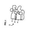
先ず図1に示すように、参照番号10は、2つの損傷していない椎骨14と16の間を伸張する損傷した椎間円板12を有する脊柱を指している。代表的な外科的切除術では、損傷した円板12を取り除いて、2つの損傷していない椎骨14と16の間に空隙を作り出す。この処置は、前方、前側方、側方、又は当業者には既知のこの他の接近法によって行われる。 First, as shown in FIG. 1,
次に図2では、人工器官18が、椎骨14と16の間の空隙に充填されている。 Next, in FIG. 2, the
次に図3−5では、椎間円板人工器官20が、図2の人工器官18として使用されている。本発明の或る実施形態による椎間円板人工器官20は、終板アッセンブリ22、24と核要素26を含んでいる。終板アッセンブリ22は、外側面28と内側面30を有している。この実施形態では、面30は、比較的平坦且つ滑らかで、鏡面仕上げが施されている。面30は、溝30を更に含んでいる。終板アッセンブリ24は、外側面34と内側面36を有している。面36は、比較的平坦且つ滑らかで、鏡面仕上げが施されている。面36は、溝の様な連結機構37を更に含んでいる。関節運動をする内側面30、36は、この実施形態では図示のように平坦で鏡面仕上げが施されているが、別の実施形態では、関節運動面には、潤滑を改善し摩擦と摩耗を低減するため、溝、窪み、又は他の造形が形成されている。これらの面は、耐摩耗性を改善するため、イオン注入、ダイアモンド又はダイアモンド様被覆、又は面を元の面より固くする他の方法の様な様々な技法の何れかで処理される。 3-5, the
核要素26は、端面40と42有する可撓性本体38を含んでいる。核要素26は、図5に示すように、長手軸44(図3)に垂直な平面から見て、概ね円形の断面を有している。別の断面形状が望ましいこともあり、単一の核要素26で、垂直平面の位置によって断面形状が変化するものもある。この実施形態では、端面40と42は、比較的平坦且つ平行で、それぞれ、リッジの様な連結機構46、48が組み込まれている。端面40と42は、可撓性本体38と一体でもよいし、機械的に又は接着剤で可撓性本体38に取り付けられていてもよい。例えば、図4に示すように、可撓性本体38上に形成されたリッジの様な連結機構50が、端面42上に形成された溝のような連結機構52と係合する。別の実施形態では、核要素は、湾曲した端面、又は互いに対して角度の付いた端面を有している。 The
終板アッセンブリ22、24は、コバルト−クロム合金、チタン合金、ニッケルチタン合金、及び/又はステンレス鋼合金の様な金属を含め、適した生体適合性のある材料であれば、どの様な材料で形成してもよい。酸化アルミニウム又はアルミナ、酸化ジルコニウム又はジルコニア、微粒ダイアモンドの成形体、及び/又は熱分解炭素の様なセラミック材料も適している。ポリエーテルエーテルケトン(PEEK)、炭素強化PEEK、又はポリエーテルケトンケトン(PEKK)の様なポリアリールエーテルケトン(PAEK)類の何れか、ポリスルホン、ポリエーテルイミド、ポリイミド、超高分子量ポリエチレン(UHMWPE)、及び/又は架橋UHMWPEを含め、ポリマー材も使用することができる。 The endplate assemblies 22, 24 can be any suitable biocompatible material, including metals such as cobalt-chromium alloys, titanium alloys, nickel titanium alloys, and / or stainless steel alloys. It may be formed. Also suitable are ceramic materials such as aluminum oxide or alumina, zirconium oxide or zirconia, particulate diamond compacts, and / or pyrolytic carbon. Polyether ether ketone (PEEK), carbon reinforced PEEK, or polyaryl ether ketone (PAEK) such as polyether ketone ketone (PEKK), polysulfone, polyetherimide, polyimide, ultra high molecular weight polyethylene (UHMWPE) Polymer materials can also be used, including, and / or crosslinked UHMWPE.
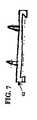
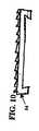
外側面28、34は、移植された人工器官の固定を強化する造形又は被覆(図示せず)を含んでいてもよい。例えば、面は、化学エッチング、ビード吹き付け、砂研磨、研削、セレーション加工、ダイアモンド切削などで粗してもよい。外側面28、34の全部又は一部を、ヒドロキシアパタイト(HA)、リン酸三カルシウム(TCP)、及び/又は炭酸カルシウムの様な生体適合性で且つ骨伝導性の材料で被覆して骨の生長と固定を促してもよい。代わりに、β型形質転換増殖因子(TGF)上科からの蛋白質や、BMP2又はBMP7の様な骨形態形成蛋白質の様な骨誘導被覆を使用してもよい。他の適した造形としては、初期固定のための図6の終板アッセンブリ60の上に示すスパイク、例えば側方及び前方への移動を防ぐための図7、8の終板アッセンブリ62の上に示すリッジ又はキール、図9、10の終板アッセンブリ64の上に示すセレーション又はダイアモンド切削面、フィン、ポスト、及び/又は他の表面模様がある。 The
図3−5に戻るが、可撓性本体38は、終板の物質より弾性係数が低い1つ又は複数の弾性材料で形成されている。適した材料には、ポリオレフィンゴムの様な重合エラストマー、ポリウレタン(ポリエーテルウレタン、ポリカーボネートウレタン、及び表面修飾末端基有り又は無しのポリウレタンを含む)、シリコンと表面修飾末端基有り又は無しのポリウレタンとのコポリマー、シリコン、ヒドロゲルが含まれる。ポリイソブチレンゴム、ポリイソプレンゴム、ネオプレンゴム、ニトリルゴム、及び/又は5−メチル−1,4−ヘキサジエンの加硫ゴムも適している。 Returning to FIGS. 3-5, the
核要素の端面40、42は、核要素26の耐摩耗性及び関節運動特性を強化するため、修正され、処理され、被覆され、或いは内張が施される。これらの耐摩耗性及び関節運動特性は、コバルト−クロム合金、チタン合金、ニッケルチタン合金、及び/又はステンレス鋼合金によって提供される。酸化アルミニウム又はアルミナ、酸化ジルコニウム又はジルコニア、微粒ダイアモンドの成形体、及び/又は熱分解炭素の様なセラミック材料も適している。PEEK、炭素強化PAEK、又はPEKKの様なPAEK類の何れか、ポリスルホン、ポリエーテルイミド、ポリイミド、UHMWPE、及び/又は架橋UHMWPEを含め、ポリマー材も使用することができる。ポリオレフィンゴム、ポリウレタン、シリコンとポリウレタンのコポリマー、及びヒドロゲルも耐摩耗性と関節運動特性を提供する。この他にも、架橋及び金属イオン注入の様な修正によって耐摩耗特性を端面40、42に持たせることもできる。 The end faces 40, 42 of the nuclear element are modified, treated, covered or lined to enhance the wear resistance and articulation characteristics of the
図3−5の実施形態は、円形の終板アッセンブリを示しているが、図11は、四角形の終板アッセンブリ66を示している。図12は、側辺が湾曲した四角形の終板アッセンブリ68を示している。図13は、腎臓又は心臓の形をした終板アッセンブリ70を示している。この他にも、終板の形状としては、正方形、楕円、三角形、六角形又は他の形状がある。図5の上面断面図に示すように、核要素の形状は、丸、楕円、又は拘束又は関節運動を促進する何らかの他の形状でもよい。 While the embodiment of FIGS. 3-5 shows a circular end plate assembly, FIG. 11 shows a square end plate assembly 66. FIG. 12 shows a square
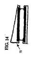
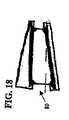
図3−5の実施形態では、外側面28と34は、比較的平行であるが、他の実施形態では、両面は、特定の前湾又は後湾角に合うように、互いに対して角度が付いている。図14−18に示すように、人工器官は、所望の前湾又は後湾角を作り出すため、傾斜付、角度付、又は楔形の形状をしている。この様な角度は、角度付の終板アッセンブリ及び/又は核要素を組み込むことによって作り出される。図14の人工器官72は、1つの角度付の終板アッセンブリを組み込むことによって角度が付けられている。図15の人工器官74は、2つの角度付の終板アッセンブリを組み込むことによって角度が付けられている。図16の人工器官76は、1つの角度付の側面を有する核要素に平板の終板を組み込むことによって角度が付けられている。図17の人工器官78は、2つの角度付の側面を有する核要素に平板の終板を組み込むことによって角度が付けられている。図18の人工器官80は、1つの角度付の終板と1つの角度付の側面を有する核要素を組み込むことによって角度が付けられている。 In the embodiment of FIGS. 3-5, the
図4に戻るが、人工器官20は、核要素26のリッジ46、48を、終板アッセンブリの溝32、37とそれぞれ係合させることによってアッセンブリされる。アッセンブリされた人工器官20は、脊柱10(図1)の円板12を取り除くことによって作り出された空隙内へと、外側面28が椎体14の終板と係合し、外側面34が椎体16の終板と係合するように移植される。 Returning to FIG. 4, the
作動時、人工器官20は、長手軸44に平行な圧縮荷重の下で弾性変形し、長手軸44に沿って終板アッセンブリ同士を互いに引き離す力が掛かると弾性的に伸びる。人工器官20は、屈曲−伸張又は側方曲げ運動時にも変形し又は曲がる。核要素26では、可変回転中心が屈曲−伸張及び側方曲げ運動を許容するようになっている。核要素26の可撓特性は、屈曲−伸張及び側方曲げ運動時の交差剪断又は関節運動により生じる摩耗を低減する働きもする。核要素26は曲がり、終板アッセンブリ22が終板アッセンブリ24に対して、前後方向又は側方並進の変位もできるようにしている。更に、端面40、42と内側面30、36それぞれの間の境界面は、回転方向には非拘束なので、核要素26は、長手軸44回りに軸回転又は回転することができる。しかしながら、境界面は、境界面における並進運動を拘束する。終板アッセンブリ22、24は、互いに対して回転することもできる。別の実施形態では、端面40、42と内側面30、36それぞれの間の境界面の少なくとも一方は、回転又は軸回転運動ができないようになっている。核要素26の連結機構46、48の、連結機構32、37との係合は、終板アッセンブリ22、24が核要素26に対して回転することを許容しながら、核要素26が飛び出るのを防いでいる。 In operation, the
次に図19−21では、椎間円板人工器官90が、図2の人工器官18として使用されている。椎間円板人工器官90は、本発明の或る実施形態によれば、終板アッセンブリ92、94と核要素96を含んでいる。終板アッセンブリ92は、外側面98と内側面100を有している。この実施形態では、内側面100は、比較的凹型且つ滑らかで、鏡面仕上げが施されている。終板アッセンブリ94は、外側面104と内側面106を有している。面106は、比較的凹型且つ滑らかで、鏡面仕上げが施されている。この実施形態では、外側面98と104は、比較的平行であるが、他の実施形態では、先に述べたように、両外側面は、特定の前湾又は後湾角に対応できるように、互いに対して角度が付いている。 19-21, an
核要素96は、端面110と112を有する可撓性の本体108を含んでいる。図21に示すように、核要素96は、長手軸44に垂直な平面から見て、概ね円形の断面を有している。別の断面形状が望ましいこともあり、単一の核要素96で、垂直平面の位置によって断面形状が変化するものもある。この実施形態では、端面110と112は、比較的凸型である。端面110と112は、可撓性本体118と一体でもよいし、機械的に又は接着剤で可撓性本体118に取り付けられていてもよい。例えば、可撓性本体108上に形成されたリッジの様な連結機構114が、端面112上の溝のような連結機構116と係合する。 The
終板アッセンブリ92、94は、それぞれ終板アッセンブリ22、24と、同一又は同様な造形又は被覆を含め、同一又は同様な材料で形成してもよい。同様に、核要素96は、核要素26に関して上で述べたのと同じ材料で形成し、同じ耐摩耗性を備えていてもよい。人工器官90、終板アッセンブリ92、94及び核要素96は、図6−18で上に述べた様な形状としてもよい。
図20に示すように、人工器官90は、端面110、112をそれぞれ内側面100、106に接触させた状態に配置してアッセンブリされる。アッセンブリされた人工器官90は、脊柱10(図1)の円板12を取り除くことによって作り出された空隙内へと、外側面98が椎体14の終板と係合し、外側面104が椎体16の終板と係合するように移植される。 As shown in FIG. 20, the
作動時、人工器官90は、長手軸44に平行な圧縮荷重の下で弾性変形する。人工器官90は、屈曲−伸張又は側方曲げ運動時にも変形し又は曲がる。核要素96は、曲がって、前後方向又は側方並進の変位もできるようにしている。核要素96では、可変回転中心が屈曲−伸張及び側方曲げ運動を許容するようになっている。核要素96の可撓特性は、屈曲−伸張及び側方曲げ運動時の交差剪断又は関節運動により生じる摩耗を低減する働きもする。更に、端面110、112と内側面100、106それぞれの間の境界面は非拘束なので、核要素96は、長手軸44回りに回転することができる。終板アッセンブリ92、94は、互いに対して回転することもできる。凹型の内側面100、106は、終板アッセンブリ22、24が核要素に対して回転することを許容しながら、核要素26が飛び出るのを防いでいる。 In operation, the
図22−27に示すように、様々な代替案の終板アッセンブリ、核要素及び連結機構の設計によって、軸回転を許容しながら側方並進運動を制限することができる。例えば、図22では、椎間円板人工器官120が、図2の人工器官18として使用されている。椎間円板人工器官120は、終板アッセンブリ122、124と核要素126を含んでいる。終板アッセンブリ122、124は、それぞれ外側面128、130と内側面132、134を有している。内側面132、134は、凹面及び凸面部を含んでおり、鏡面仕上げが施され滑らかである。凹面及び凸面部は、内側面上に同芯輪を形成している。図22の実施形態では、内側面132、134の凸面突起136、138は、連結機構として機能する。終板アッセンブリ122、124は、それぞれ終板アッセンブリ22、24と、同一又は同様な造形又は被覆を含め、同一又は同様な材料で形成してもよい。 As shown in FIGS. 22-27, various alternative endplate assemblies, core elements, and coupling mechanism designs can limit lateral translation while allowing axial rotation. For example, in FIG. 22, an
核要素126は、端面142、144を有する可撓性の本体140を含んでいる。この実施形態では、端面142、144は、端面の略中心にある窪みである、連結機構146、148を備えている。核要素126は、核要素26に関して上に述べたものと、同じ材料で形成し、同じ耐摩耗特性を有していてもよい。 The
人工器官120は、端面142、144をそれぞれ内側面132、134に接触させて配置することによってアッセンブリされる。具体的には、終板アッセンブリの連結機構136、138を核要素の連結機構146、148と係合させる。アッセンブリされた人工器官120は、脊柱10(図1)の円板12を取り除くことによって作り出された空隙内へと、外側面128が椎体14の終板と係合し、外側面130が椎体16の終板と係合するように移植される。 The
図23では、椎間円板人工器官150が、図2の人工器官18として使用されている。椎間円板人工器官150は、丸味の付いた終板アッセンブリ152、154と核要素156を含んでいる。終板アッセンブリ152、154は、それぞれ外側面158、160と内側面162、164を有している。図9の実施形態と同様に、内側面162、164は、凹面及び凸面部を含んでおり、鏡面仕上げが施され滑らかである。凹面及び凸面部は、内側面上に同芯輪を形成している。この実施形態では、内側面162、164の凸状輪突起166、168は、それぞれ、核要素156の端面174、176上に形成されている凹状輪である連結機構170、172と係合する連結機構として機能する。 In FIG. 23, an
図24では、椎間円板人工器官180が、図2の人工器官18として使用されている。人工器官180は、本発明のこの実施形態によれば、終板アッセンブリ182、184と核要素186を含んでいる。終板アッセンブリ182、184は、それぞれ外側面188、190と内側面192、194を有している。内側面192、194は、凹面及び凸面部を含んでおり、鏡面仕上げが施され滑らかである。図24の実施形態では、内側面192、194の凸状突起196、198は、連結機構として機能する。終板アッセンブリ182、184は、それぞれ終板アッセンブリ22、24と、同一又は同様な造形又は被覆を含め、同一又は同様な材料で形成してもよい。 In FIG. 24, an
核要素186は、関節運動面202を有する可撓性の本体200を含んでいる。この実施形態では、核要素186は、連結機構として働く中央開口204を有する輪の形をしている。核要素186は、核要素26に関して上に述べたものと、同じ材料で形成し、同じ耐摩耗特性を有していてもよい。 The
人工器官180は、核要素186を内側面190、194それぞれの間に配置することによってアッセンブリされる。具体的には、終板アッセンブリの連結機構196、198を核要素の連結機構204と係合させる。アッセンブリされた人工器官180は、脊柱10(図1)の円板12を取り除くことによって作り出された空隙内へと、外側面188が椎体14の終板と係合し、外側面192が椎体16の終板と係合するように移植される。 The
作動時、関節運動面202と内側面190、194の間の境界面は、長手軸44回りの回転と、制限された側方並進運動の両方ができるようになっている。人工器官180は、長手軸44に平行な圧縮荷重の下で弾性変形し、衝撃を吸収して減衰効果を提供する。終板アッセンブリ182、184と核要素186の間の関節運動境界面と、可撓性の本体200の弾性の両方によって、屈曲−伸張及び側方曲げ運動ができるようになっている。 In operation, the interface between the articulating
図25では、椎間円板人工器官210が、図2の人工器官18として使用されている。椎間円板人工器官210は、本発明のこの実施形態によれば、終板アッセンブリ212、214と核要素216を含んでいる。終板アッセンブリ212は、外側面218と内側面220を有している。図25の実施形態では、内側面220は、比較的凹型且つ滑らかで、鏡面仕上げが施されている。終板アッセンブリ214は、外側面222と内側面224を有している。内側面224は、比較的凹型で、突出する柱である連結機構226を含んでいる。 In FIG. 25, an
核要素216は、可撓性の層228と、可撓性の層228に取り付けられた外側の関節運動層230、232を含んでいる。関節運動層230は凸型である。関節運動層232は、概ね凸型であるが、連結機構として働く陥凹部234を備えている。別の実施形態では、陥凹部が関節運動層232に形成されている。 The
終板アッセンブリ212、214は、それぞれ終板アッセンブリ22、24と、同一又は同様な造形又は被覆を含め、同一又は同様な材料で形成してもよく、従って、これ以上詳細には説明しない。可撓性の層228は、核要素26に関して上に述べたものと、同じ可撓性又は弾性材料で形成してもよい。関節運動層230、232は、終板アッセンブリ22、24と同一又は同様な材料で形成してもよい。代わりに、関節運動層230、232は、核要素26に関して上に述べたものと同一又は同様の材料に、耐摩耗性を高めるため架橋又はイオン注入の様な修正を加えた材料で形成してもよい。
図25に示すように、人工器官210は、終板アッセンブリ212の凹型の内側面220を核要素216の凸型の関節運動層220と係合させることによってアッセンブリされる。関節運動層232は、終板アッセンブリ214の内側面224と係合し、連結機構234を連結機構226と係合させる。 As shown in FIG. 25, the
作動時、凸型の関節運動層230と終板アッセンブリ212の凹型面220との間の境界面は、長手軸44回りの回転と、制限された側方並進運動の両方ができるようになっている。関節運動層232は、内側面224の連結機構226回りに回転することはできるが、核要素216と終板アッセンブリ214の間の側方並進運動は、殆ど又は全く許容されていない。人工器官210は、長手軸44に平行な圧縮荷重の下で弾性変形し、衝撃を吸収して減衰効果を提供する。終板アッセンブリ212と核要素216の間の関節運動境界面と、可撓性の層228の弾性の両方によって、屈曲−伸張、側方曲げ、又は長手軸44回りの軸回転運動ができるようになっている。 In operation, the interface between the
図26では、椎間円板人工器官240が、図2の人工器官18として使用されている。椎間円板人工器官240は、本発明のこの実施形態によれば、終板アッセンブリ242、244と核要素246を含んでいる。終板アッセンブリ242は、外側面248と内側面250を有している。図26の実施形態では、内側面250は、比較的凹型且つ滑らかで、鏡面仕上げが施されている。 In FIG. 26, an
終板アッセンブリ244は、外側面252と内側面254を有している。内側面254は、比較的平坦で、突起である連結機構256と溝である連結機構258を含んでいる。
核要素246は、可撓性の層260と、可撓性の層260に取り付けられた外側の関節運動層262、264を含んでいる。関節運動層262は凸型である。関節運動層264は、比較的平坦で、共に連結機構として働くリッジ266と窪み268を備えている。 The
終板アッセンブリC2、C4は、それぞれ終板アッセンブリ22、24と、同一又は同様な造形又は被覆を含め、同一又は同様な材料で形成してもよく、従って、これ以上詳細には説明しない。可撓性の層260は、核要素26に関して上に述べたものと、同じ可撓性又は弾性材料で形成してもよい。関節運動層262、264は、終板アッセンブリ22、24と同一又は同様な材料で形成してもよい。代わりに、関節運動層262、264は、核要素26に関して上に述べたものと同一又は同様の材料に、耐摩耗性を高めるため架橋又はイオン注入の様な修正を加えた材料で形成してもよい。 End plate assemblies C2, C4 may be formed of the same or similar materials as
図26に示すように、人工器官240は、終板アッセンブリ242の凹型の内側面250を核要素246の凸型の関節運動層262と係合させることによってアッセンブリされる。関節運動層264は、終板アッセンブリ244の内側面254と係合し、連結機構266、268を、それぞれ連結機構258、256と係合させる。 As shown in FIG. 26, the
作動時、凸型の関節運動層262と終板アッセンブリ242の凹型面250との間の境界面は、長手軸44回りの回転と、制限された側方並進運動の両方ができるようになっている。関節運動層264は、内側面254に対して、軸44回りに回転できるようになっているか、或いは、境界面が機械的に又は接着剤で固定され回転できないようになっている。人工器官240は、長手軸44に平行な圧縮荷重の下で弾性変形し、衝撃を吸収して減衰効果を提供する。終板アッセンブリ242と核要素246の間の関節運動境界面と、可撓性の層260の弾性の両方によって、屈曲−伸張、側方曲げ、又は長手軸44回りの軸回転運動ができるようになっている。 In operation, the interface between the
図27では、椎間円板人工器官270が、図2の人工器官18として使用されている。椎間円板人工器官270は、本発明のこの実施形態によれば、終板アッセンブリ272、274と核要素276を含んでいる。終板アッセンブリ272は、外側面278と内側面280を有している。図27の実施形態では、内側面280は、同芯円、ほぞ穴形状の溝(dove tail shaped grooves)である連結機構282を有している。 In FIG. 27, an
終板アッセンブリ274は、外側面284と内側面286を有している。内側面286は、比較的滑らか且つ凹型で、鏡面仕上げが施されている。
核要素276は、可撓性の層288と、可撓性の層290に取り付けられた外側の関節運動層290、292を含んでいる。関節運動層292は凸型である。関節運動層290は、平坦な部分と、同芯円、ほぞ形状の突起(dove tail shaped projections)である連結機構294を含んでいる。 The
終板アッセンブリ272、274は、それぞれ終板アッセンブリ22、24と、同一又は同様な造形又は被覆を含め、同一又は同様な材料で形成してもよい。可撓性の層288は、核要素26に関して上に述べたものと、同じ可撓性又は弾性材料で形成してもよい。関節運動層290、292は、終板アッセンブリ22、24と同一又は同様な材料で形成してもよい。代わりに、関節運動層290、292は、核要素26に関して上に述べたものと同一又は同様の材料に、耐摩耗性を高めるため架橋又はイオン注入の様な修正を加えた材料で形成してもよい。
図27に示すように、人工器官270は、終板アッセンブリ274の凹型の内側面286を核要素276の凸型の関節運動層292と係合させることによってアッセンブリされる。関節運動層290は、終板アッセンブリ272の内側面280と係合し、連結機構282を、連結機構294と係合させる。 As shown in FIG. 27, the
作動時、凸型の関節運動層292と終板アッセンブリ274の凹型面286との間の境界面は、長手軸44回りの回転と、制限された側方並進運動の両方ができるようになっている。関節運動層290は、内側面280に対して、軸44回りに回転できるようになっているが、連結機構282、294が、側方運動を防止又は制限している。人工器官270は、長手軸44に平行な圧縮荷重の下で弾性変形し、衝撃を吸収して減衰効果を提供する。終板アッセンブリ274と核要素276の間の関節運動境界面と、可撓性の層288の弾性の両方によって、屈曲−伸張、側方曲げ、又は長手軸44回りの軸回転運動ができるようになっている。代替実施形態では、282、294に使用されている様な連結機構を、終板アッセンブリ274と核要素276の間の境界面に使用している。この代替案では、側方並進運動が防止又は制限されるが、軸44回りに回転することはできる。この代替実施形態では、核要素の柔軟性によって、なお屈曲−伸張、及び側方曲げ運動ができるようになっている。 In operation, the interface between the
図28では、椎間円板人工器官300が、図2の人工器官18として使用されている。椎間円板人工器官300は、本発明のもう1つの実施形態によれば、終板アッセンブリ302、304と核要素306を含んでいる。終板アッセンブリ302は、外側面308と内側面310を有している。図28の実施形態では、内側面310は、比較的凹型且つ滑らかで、鏡面仕上げが施されている。 In FIG. 28, an
終板アッセンブリ304は、外側面314と内側面316を有している。内側面316は、比較的平坦で、溝である連結機構318を含んでいる。外側面308と314は、比較的平行であるか、又は特定の前湾又は後湾角に対応するため互いに対して角度が付いている。
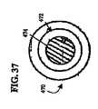
核要素306は、可撓性の層320と、可撓性の層320に取り付けられた関節運動層322を含んでいる。関節運動層322は凸型面324を有している。可撓性の層320は、リッジである連結機構326を含んでいる。核要素306は、長手軸44に垂直な平面から見て、概ね円形の断面を有している。別の断面形状が望ましいこともあり、単一の核要素306で、垂直平面の位置によって断面形状が変化するものもある。 The
終板アッセンブリ302、304は、それぞれ終板アッセンブリ22、24と、同一又は同様な造形又は被覆を含め、同一又は同様な材料で形成してもよく、従って、これ以上詳細には説明しない。可撓性の層320は、核要素26に関して上に述べたものと、同じ可撓性又は弾性材料で形成してもよい。関節運動層322は、終板アッセンブリ22、24と同一又は同様な材料で形成してもよい。代わりに、関節運動層322は、核要素26に関して上に述べたものと同一又は同様の材料に、耐摩耗性を高めるため架橋又はイオン注入の様な修正を加えた材料で形成してもよい。
図28に示すように、人工器官300は、可撓性の層320を終板アッセンブリ304の内側面316に、機械的に又は接着剤で取り付けることによってアッセンブリされる。連結機構318は、連結機構326と係合して機械的取り付けを形成する。追加して、又は代わりに、接着剤を使って、可撓性の層320と内側面316を取り付けてもよい。関節運動層322の凸型面324は、凹型の内側面310の上に配置される。アッセンブリされた構成要素302−306は、脊柱10(図1)の円板12を取り除くことによって作り出された空隙内へと、外側面308が椎体14の終板と係合し、外側面314が椎体16の終板と係合するように移植される。 As shown in FIG. 28, the
作動時、関節運動層322の凸型面324は、終板アッセンブリ92の凹型面310と関節運動を行う。人工器官300は、長手軸44に平行な圧縮荷重の下で弾性変形し、衝撃を吸収して減衰効果を提供する。終板アッセンブリ302と核要素306の間の関節運動境界面と、可撓性の層320の弾性の両方によって、屈曲−伸張、側方曲げ、又は長手軸44回りの軸回転運動ができるようになっている。終板アッセンブリ302、304も、互いに対して回転する。 In operation, the
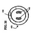
図29では、椎間円板人工器官330が、図2の人工器官18として使用されている。椎間円板人工器官330は、本発明のもう1つの実施形態によれば、終板アッセンブリ332、334と核要素336を含んでいる。終板アッセンブリ332は、外側面338と内側面340を有している。図16の実施形態では、内側面340は、比較的平坦で、溝である連結機構342を含んでいる。 In FIG. 29, an
終板アッセンブリ334は、外側面344と内側面346を有している。内側面346は、少なくとも部分的には凸型で、鏡面仕上げで滑らかになっている。外側面338と344は、比較的平行であるか、又は特定の前湾又は後湾角に対応するため互いに対して角度が付いている。 The
核要素336は、可撓性の層350と、可撓性の層350に取り付けられた関節運動層352を含んでいる。関節運動層352は凹型面354を有している。可撓性の層350は、リッジである連結機構356を含んでいる。核要素336は、長手軸44に垂直な平面から見て、概ね円形の断面を有している。別の断面形状が望ましいこともあり、単一の核要素336で、垂直平面の位置によって断面形状が変化するものもある。 The
終板アッセンブリ332、334は、それぞれ終板アッセンブリ22、24と、同一又は同様な造形又は被覆を含め、同一又は同様な材料で形成してもよく、従って、これ以上詳細には説明しない。可撓性の層350は、核要素26に関して上に述べたものと、同じ可撓性又は弾性材料で形成してもよい。関節運動層352は、終板アッセンブリ22、24と同一又は同様な材料で形成してもよい。代わりに、関節運動層352は、核要素26に関して上に述べたものと同一又は同様の材料に、耐摩耗性を高めるため架橋又はイオン注入の様な修正を加えた材料で形成してもよい。
図29に示すように、人工器官330は、可撓性の層350を終板アッセンブリ332の内側面340に、機械的に又は接着剤で取り付けることによってアッセンブリされる。連結機構342は、連結機構356と係合して機械的取り付けを形成する。追加して、又は代わりに、接着剤を使って、可撓性の層350と内側面340を取り付けてもよい。関節運動層352の凹型面354は、凸型の内側面346の上に配置される。アッセンブリされた構成要素332−336は、脊柱10(図1)の円板12を取り除くことによって作り出された空隙内へと、外側面338が椎体14の終板と係合し、外側面344が椎体16の終板と係合するように移植される。 As shown in FIG. 29, the
作動時、関節運動層352の凹型面354は、終板アッセンブリ334の凸型面346と関節運動を行う。人工器官330は、長手軸44に平行な圧縮荷重の下で弾性変形し、衝撃を吸収して減衰効果を提供する。終板アッセンブリ334と核要素336の間の関節運動境界面と、可撓性の層350の弾性の両方によって、屈曲−伸張、側方曲げ、又は長手軸44回りの軸回転運動ができるようになっている。終板アッセンブリ332、334も、互いに対して回転する。 In operation, the
図30では、椎間円板人工器官360が、図2の人工器官18として使用されている。椎間円板人工器官360は、本発明のもう1つの実施形態によれば、終板アッセンブリ362、364と、核要素366と、核要素367を含んでいる。終板アッセンブリ362は、外側面368と内側面370を有している。図30の実施形態では、内側面370は、比較的平坦で、溝である連結機構372を含んでいる。 In FIG. 30, an
終板アッセンブリ364は、外側面374と内側面376を有している。図30の実施形態では、内側面376は、比較的平坦で、溝である連結機構378を含んでいる。外側面368と374は、比較的平行であるか、又は特定の前湾又は後湾角に対応するため互いに対して角度が付いている。
核要素366は、可撓性の層380と、可撓性の層380に取り付けられた関節運動層382を含んでいる。関節運動層382は凹型面384を有している。可撓性の層380は、リッジである連結機構386を含んでいる。核要素366は、長手軸44に垂直な平面から見て、概ね円形の断面を有している。別の断面形状が望ましいこともあり、単一の核要素366で、垂直平面の位置によって断面形状が変化するものもある。 The
核要素367は、可撓性の層388と、可撓性の層388に取り付けられた関節運動層390を含んでいる。関節運動層390は凸型面392を有している。可撓性の層388は、リッジである連結機構394を含んでいる。核要素367は、長手軸44に垂直な平面から見て、概ね円形の断面を有している。別の断面形状が望ましいこともあり、単一の核要素367で、垂直平面の位置によって断面形状が変化するものもある。 The
終板アッセンブリ362、364は、それぞれ終板アッセンブリ22、24と、同一又は同様な造形又は被覆を含め、同一又は同様な材料で形成してもよく、従って、これ以上詳細には説明しない。可撓性の層380、388は、核要素26に関して上に述べたものと、同じ可撓性又は弾性材料で形成してもよい。関節運動層382、390は、終板アッセンブリ22、24と同一又は同様な材料で形成してもよい。代わりに、関節運動層382、390は、核要素26に関して上に述べたものと同一又は同様の材料に、耐摩耗性を高めるため架橋又はイオン注入の様な修正を加えた材料で形成してもよい。
図30に示すように、人工器官360は、可撓性の層380を終板アッセンブリ362の内側面370に、機械的に又は接着剤で取り付けることによってアッセンブリされる。連結機構372は、連結機構386と係合して機械的取り付けを形成する。追加して、又は代わりに、接着剤を使って、可撓性の層380と内側面370を取り付けてもよい。可撓性の層388は、終板アッセンブリ364の内側面376に、機械的に及び/又は接着剤で取り付けられる。連結機構378は、連結機構394と係合して機械的取り付けを形成する。追加して、又は代わりに、接着剤を使って、可撓性の層388と内側面376を取り付けてもよい。関節運動層382の凹型面384は、凸型の関節運動面392の上に配置される。アッセンブリされた構成要素は、脊柱10(図1)の円板12を取り除くことによって作り出された空隙内へと、外側面368が椎体14の終板と係合し、外側面374が椎体16の終板と係合するように移植される。 As shown in FIG. 30, the
作動時、関節運動層382の凹型面384は、関節運動層390の凸型面392と関節運動を行う。人工器官360は、長手軸44に平行な圧縮荷重の下で弾性変形し、衝撃を吸収して減衰効果を提供する。核要素366と核要素367の間の関節運動境界面と、可撓性の層380、388の弾性の両方によって、屈曲−伸張、側方曲げ、又は長手軸44回りの軸回転運動ができるようになっている。終板アッセンブリ362、364も、互いに対して回転する。 In operation, the concave surface 384 of the
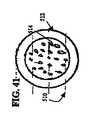
図31−32では、椎間円板人工器官400が、図2の人工器官18として使用されている。椎間円板人工器官400は、本発明のこの実施形態によれば、終板アッセンブリ402、404と核要素406を含んでいる。終板アッセンブリ402は、外側面408と内側面410を有している。図31の実施形態では、内側面410は、鏡面仕上げで滑らかになった比較的凹型の部分を含んでいる。終板アッセンブリ404は、外側面412と内側面414を有している。内側面414は、比較的凹型の部分を含んでいる。緩衝器である連結機構416が、内側面410、414から突き出ている。 31-32, an
核要素406は、可撓性の層418と、可撓性の層418に取り付けられた外側関節運動層420、422を含んでいる。関節運動層420、422は、溝である連結機構424を含んでいる。1つ又はそれ以上の繋ぎ紐426が、終板アッセンブリ402と404の間を伸張している。 The
終板アッセンブリ402、404は、それぞれ終板アッセンブリ22、24と、同一又は同様な造形又は被覆を含め、同一又は同様な材料で形成してもよく、従って、これ以上詳細には説明しない。可撓性の層418は、核要素26に関して上に述べたものと、同じ可撓性又は弾性材料で形成してもよい。関節運動層420、422は、終板アッセンブリ22、24と同一又は同様な材料で形成してもよい。代わりに、関節運動層420、422は、核要素26に関して上に述べたものと同一又は同様の材料に、耐摩耗性を高めるため架橋又はイオン注入の様な修正を加えた材料で形成してもよい。繋ぎ紐426は、弾性が有っても無くてもよい。繋ぎ紐は、例えば、ワイヤ、ケーブル、コード、バンド、テープ、シートの様な補強材で形成してもよい。繋ぎ紐は、終板アッセンブリ22、24又は核要素26に関して上に述べた、UHMWPEの様な、材料の何れで形成してもよい。或る実施形態では、繋ぎ紐426は、組み編みされ、編まれ、又は織られている。
図31に示すように、人工器官400は、核要素406を終板アッセンブリ402、404の内側面410、414の間に配置することによってアッセンブリされる。緩衝器416は、関節運動層420、422の溝424に沿って移動するように配置される。実施形態によっては、2つから4つの緩衝器/溝の境界部が設けられている。1つ又は複数の繋ぎ紐26が終板アッセンブリ402と404の間を伸張し、屈曲/伸張、側方曲げ、又は軸回転力が加えられた際に、人工器官400に追加的な安定性を提供し、及び/又は追加的な拘束を加える。図31に示すように、繋ぎ紐426は、終板アッセンブリ402と404の間を、核要素406を通過すること無く伸張している。アッセンブリされた人工器官400は、脊柱10内の椎骨14と16の間に配置される。 As shown in FIG. 31, the
図31−32を再度参照するが、作動時、緩衝器416は、関節運動層420、422の溝424に沿って移動し、長手軸44回りに制限された回転ができるようにしている。回転は、緩衝器416の長さに比較した溝424の長さで制限される。例えば、緩衝器416と溝424の長さがほぼ同じであれば、回転は殆ど又は全くできない。或る種の実施形態では、1度から12度の間の回転ができるようになっている。又或る種の実施形態では、回転を3度から10度の間に制限している。繋ぎ紐426も、屈曲/伸張、側方曲げ、及び/又は軸回転運動の際に人工器官400を拘束する。アッセンブリの拘束の範囲内で、人工器官400は、長手軸44に平行な圧縮荷重の下で弾性変形し、衝撃を吸収して減衰効果を提供する。終板アッセンブリ402、404と核要素406の間の関節運動境界面と、可撓性の層418の弾性の両方によって、屈曲−伸張、側方曲げ、又は長手軸44回りの軸回転運動ができるようになっている。 Referring again to FIGS. 31-32, in operation, the
図33−34では、椎間円板人工器官430が、図2の人工器官18として使用されている。椎間円板人工器官430は、本発明のこの実施形態によれば、終板アッセンブリ432、434と核要素436を含んでいる。終板アッセンブリ432は、内側面438を有している。図33の実施形態では、内側面438は、鏡面仕上げで滑らかになった比較的凹型の部分を含んでいる。終板アッセンブリ434は、内側面440を有している。内側面440は、比較的凹型の部分を含んでいる。緩衝器である連結機構441が、内側面438、440から突き出ている。 33-34, an
核要素436は、可撓性の層442と、可撓性の層442に取り付けられた外側関節運動層444、446を含んでいる。関節運動層444、446は、溝である連結機構447を含んでいる。1つ又はそれ以上の繋ぎ紐448が、関節運動層444と446の間を、可撓性の層442を通って対角方向に伸張している。加えて、又は代わりに、1つ又はそれ以上の繋ぎ紐449が、関節運動層444と446の間を、可撓性の層442を通って、軸44と比較的平行に伸張している。 The
終板アッセンブリ432、434は、それぞれ終板アッセンブリ22、24と、同一又は同様な造形又は被覆を含め、同一又は同様な材料で形成してもよく、従って、これ以上詳細には説明しない。可撓性の層442は、核要素26に関して上に述べたものと、同じ可撓性又は弾性材料で形成してもよい。関節運動層444、446は、終板アッセンブリ22、24と同一又は同様な材料で形成してもよい。代わりに、関節運動層444、446は、核要素26に関して上に述べたものと同一又は同様の材料に、耐摩耗性を高めるため架橋又はイオン注入の様な修正を加えた材料で形成してもよい。繋ぎ紐448、449は、弾性が有っても無くてもよい。繋ぎ紐は、例えば、ワイヤ、ケーブル、コード、バンド、テープ、シートの様な補強材で形成してもよい。繋ぎ紐は、終板アッセンブリ22、24又は核要素26に関して上に述べた、UHMWPEの様な、材料の何れで形成してもよい。或る実施形態では、繋ぎ紐448、449は、組み編みされ、編まれ、又は織られている。
図33に示すように、人工器官430は、核要素436を終板アッセンブリ432、434の内側面438、440の間に配置することによってアッセンブリされる。緩衝器441は、関節運動層444、446の溝447に沿って移動するように配置される。実施形態によっては、2つから4つの緩衝器/溝の境界部が設けられている。1つ又は複数の繋ぎ紐448、449が関節運動層444と446の間を伸張し、屈曲/伸張、側方曲げ、又は軸回転力が加えられた際に、人工器官430に追加的な安定性を提供し、及び/又は追加的な拘束を加える。アッセンブリされた人工器官430は、脊柱10内の椎骨14と16の間に配置される。 As shown in FIG. 33, the
作動時、緩衝器441は、関節運動層444、446の溝447に沿って移動し、長手軸44回りに制限された回転ができるようにしている。回転は、緩衝器441の長さに比較した溝447の長さで制限される。例えば、緩衝器441と溝447の長さがほぼ同じであれば、回転は殆ど又は全くできない。或る種の実施形態では、1度から12度の間の回転ができるようになっている。又或る種の実施形態では、回転を3度から10度の間に制限している。繋ぎ紐448、449も、屈曲/伸張、側方曲げ、及び/又は軸回転運動の際に人工器官430を拘束する。例えば、対角方向に配置されている繋ぎ紐448は、溝447が緩衝器441と衝突した際に、可撓性の層442を捻り剪断に対して補強している。繋ぎ紐449は、可撓性の層442を側方剪断に対して補強している。繋ぎ紐448と449は、単独で、又は互いに組み合わせて用いることができる。アッセンブリの拘束の範囲内で、人工器官430は、長手軸44に平行な圧縮荷重の下で弾性変形し、衝撃を吸収して減衰効果を提供する。終板アッセンブリ432、434と核要素436の間の関節運動境界面と、可撓性の層442の弾性の両方によって、屈曲−伸張、側方曲げ、又は長手軸44回りの軸回転運動ができるようになっている。 In operation, the
図35−36では、椎間円板人工器官450が、図2の人工器官18として使用されている。人工器官450は、終板アッセンブリ452、454と核要素456を含んでおり、また上に述べた人工器官の構造の何れを含んでいてもよい。核要素456は、1つ又は複数の修正要素460を含んでいる可撓性の層458を含んでいる。可撓性の層458は、核要素26に関して上に述べたものと、同じ可撓性又は弾性材料で形成してもよい。 35-36, an
図35−36に示すように、人工器官450は、図36の上面断面図から見て、2つの腎臓の形をした修正要素460を含んでいる。この人工器官450は、修正要素460の一方が前部に、他方が後部に配置され、伸張及び/又は曲げ運動を促進するように移植される。代わりに、人工器官450は、修正要素460が横方向に位置し、側方曲げを促進又は制約するように、回転させて移植することもできる。 As shown in FIGS. 35-36, the
図37−38に示すように、人工器官470は、単一の修正要素474を有する核要素472を含んでいる。この実施形態では、単一の修正要素474は、核要素472の中心近くに配置されており、核要素の中心領域が、その周辺領域とは異なる剛性を示すようにしている。単一の修正要素474は、球又は楕円体を含めどの様な幾何学的形状に形成してもよい。修正要素474は、耐摩耗性があるように丸味の付いた縁部を有している。 As shown in FIGS. 37-38, the
図39−40に示すように、人工器官490は、単一の修正要素494を有する核要素492を含んでいる。この実施形態では、修正要素494は、核要素492の中の輪の形状をした領域である。 As shown in FIGS. 39-40, the
図41−42に示すように、人工器官50は、核要素中に分散配置されている複数の修正要素514を有する核要素512を含んでいる。 As shown in FIGS. 41-42, the
修正要素460、474、494、514は、隣接する可撓性の層の硬度、剛性、柔軟性又はコンプライアンスを制御、調節又は修正する材料及び/又は空隙である。修正要素460、474、494、514は、それぞれ核要素456、472、492、512の剛性を変化させるために、どの様な寸法、形状又は材料であってもよい。例えば、核要素456、472、492、512の或る領域に、それぞれ修正要素460、474、494、514を設けて、修正された領域と修正されていない領域の間に異なる剛性を作り出してもよい。様々な修正要素の構成を使って核要素の剛性を変えることができ、その数例を上に説明した。修正要素は、可撓性の層内の不連続の物体でもよいし、修正要素を可撓性の層内に、例えば半径方向に混合できるようにする徐変性の特性を有していてもよい。 The
修正要素460、474、494、514は、それぞれ、終板アッセンブリ22、24又は核要素26に関して先に述べた材料を含め、可撓性の層458、472、492、512とは異なる材料で形成してもよい。この材料は、可撓性の層の材料よりも、剛くても柔軟でもよい。修正要素460、474、494、514は、空隙でもよく、或る実施形態では、1つ又は複数の空隙が、鎮痛薬、抗炎症物質、増殖因子、抗生物質、ステロイド、苦痛薬剤、又はそれらの薬剤の組合せのような治療薬剤の保管庫として働いている。増殖因子には、β型形質転換増殖因子(TGF―β)、骨形態形成蛋白質(BMP)、組み換えヒト骨形態形成蛋白質(rhBMP)、インスリン様増殖因子、血小板由来増殖因子、線維芽細胞成長因子、又は周囲の組織の組織修復を促進する助けとなる何らかの他の成長因子が含まれる。 The
以上、本発明の代表的な実施形態について数例を詳しく説明してきたが、当業者には容易に理解頂けるように、これら代表的な実施形態には、本発明の新規な教示及び利点から実質的に逸脱すること無く、数多くの修正を加えることができる。従って、その様な修正は、全て、特許請求の範囲に定義する本発明の範囲に含まれるものとする。請求項において、手段プラス機能の句は、詳述された機能を実行するものとしてここで記述した構造を、構造的等価物のみならず等価な構造も含め、包含するよう意図している。 While several exemplary embodiments of the present invention have been described in detail above, as will be readily appreciated by those skilled in the art, these exemplary embodiments are substantially derived from the novel teachings and advantages of the present invention. Many modifications can be made without departing from the scope. Accordingly, all such modifications are intended to be included within the scope of this invention as defined in the claims. In the claims, the means-plus-function phrase is intended to encompass structures described herein as performing the detailed functions, including equivalent structures as well as structural equivalents.
Claims (60)
Translated fromJapanese第1椎骨終板と係合させるための第1終板アッセンブリと、
第2椎骨終板と係合させるための第2終板アッセンブリと、
前記第1終板アッセンブリと前記第2終板アッセンブリの間に挿間される第1可撓性核要素であって、第1端部と第2端部を備えている第1可撓性核要素と、を備えており、
前記第1端部は、前記第1終板アッセンブリと連結されて、前記第1端部の前記第1終板アッセンブリに対する並進運動を制限し、前記第2端部は、前記第2終板アッセンブリに対して回転可能になっている、脊椎移植片。In a spinal graft for insertion between two vertebral endplates,
A first endplate assembly for engaging the first vertebral endplate;
A second endplate assembly for engaging the second vertebral endplate;
A first flexible core element that is inserted between the first end plate assembly and the second end plate assembly, the first flexible core having a first end and a second end. Elements, and
The first end is connected to the first end plate assembly to limit translational motion of the first end relative to the first end plate assembly, and the second end is configured to be the second end plate assembly. A spinal graft that is rotatable relative to.
第1椎骨終板と係合させるための第1終板アッセンブリと、
第2椎骨終板と係合させるための第2終板アッセンブリと、
前記第1終板アッセンブリと前記第2終板アッセンブリの間に挿間される第1可撓性核要素であって、外側面を備えている第1可撓性核要素と、を備えており、
前記外側面は、全外側面よりは小さな面に亘る関節運動面を備えており、
前記第1終板アッセンブリは、前記第1可撓性核要素の外形と整合する形状の連結機構を備えている、脊椎移植片。In a spinal graft for insertion between two vertebral endplates,
A first endplate assembly for engaging the first vertebral endplate;
A second endplate assembly for engaging the second vertebral endplate;
A first flexible core element inserted between the first end plate assembly and the second end plate assembly, the first flexible core element having an outer surface. ,
The outer surface comprises an articulating surface over a smaller surface than the entire outer surface;
The first endplate assembly includes a linking mechanism configured to align with an outer shape of the first flexible core element.
第1椎骨終板接触面と第1内側面とを備えている第1終板アッセンブリと、
第2椎骨終板接触面と第2内側面とを備えている第2終板アッセンブリと、
前記第1内側面と前記第2内側面の間に挿間される可撓性核要素であって、第1端部と第2端部を備えている可撓性核要素と、を備えており、
前記第1端部は、前記第1内側面と連結させて、前記第1端部の前記第1終板アッセンブリに対する並進運動を防止するための連結機構を備えており、
前記第2端部は、前記第2終板アッセンブリに対して回転可能である、脊椎移植片。In a spinal graft for insertion between two vertebral endplates,
A first endplate assembly comprising a first vertebra endplate contact surface and a first inner surface;
A second endplate assembly comprising a second vertebra endplate contact surface and a second inner surface;
A flexible nuclear element inserted between the first inner surface and the second inner surface, the flexible nuclear element having a first end and a second end. And
The first end includes a connection mechanism that is connected to the first inner surface to prevent translational movement of the first end with respect to the first end plate assembly;
The spinal implant, wherein the second end is rotatable with respect to the second endplate assembly.
Applications Claiming Priority (2)
| Application Number | Priority Date | Filing Date | Title |
|---|---|---|---|
| US10/765,260US7250060B2 (en) | 2004-01-27 | 2004-01-27 | Hybrid intervertebral disc system |
| PCT/US2005/002485WO2005072660A1 (en) | 2004-01-27 | 2005-01-26 | Hybrid intervertebral disc system |
Publications (1)
| Publication Number | Publication Date |
|---|---|
| JP2007519488Atrue JP2007519488A (en) | 2007-07-19 |
Family
ID=34795441
Family Applications (1)
| Application Number | Title | Priority Date | Filing Date |
|---|---|---|---|
| JP2006551444AWithdrawnJP2007519488A (en) | 2004-01-27 | 2005-01-26 | Spinal graft |
Country Status (7)
| Country | Link |
|---|---|
| US (2) | US7250060B2 (en) |
| EP (1) | EP1715819A1 (en) |
| JP (1) | JP2007519488A (en) |
| CN (1) | CN1925817A (en) |
| AU (1) | AU2005209281A1 (en) |
| CA (1) | CA2554576A1 (en) |
| WO (1) | WO2005072660A1 (en) |
Cited By (3)
| Publication number | Priority date | Publication date | Assignee | Title |
|---|---|---|---|---|
| JP4838319B2 (en)* | 2005-11-16 | 2011-12-14 | ウォーソー・オーソペディック・インコーポレーテッド | Artificial intervertebral disc organ |
| JP2014221399A (en)* | 2008-01-16 | 2014-11-27 | エイチエイチ・スパイナル・エルエルシー | Joint replacement device |
| JPWO2021153795A1 (en)* | 2020-01-31 | 2021-08-05 |
Families Citing this family (281)
| Publication number | Priority date | Publication date | Assignee | Title |
|---|---|---|---|---|
| CA2429246C (en) | 2000-08-08 | 2011-06-07 | Vincent Bryan | Implantable joint prosthesis |
| DE60139262D1 (en) | 2000-08-28 | 2009-08-27 | Disc Dynamics Inc | SYSTEM FOR RECONSTRUCTING JOINT SURFACES OF MAMMALS |
| FR2824261B1 (en) | 2001-05-04 | 2004-05-28 | Ldr Medical | INTERVERTEBRAL DISC PROSTHESIS AND IMPLEMENTATION METHOD AND TOOLS |
| US8388684B2 (en) | 2002-05-23 | 2013-03-05 | Pioneer Signal Technology, Inc. | Artificial disc device |
| US7001433B2 (en)* | 2002-05-23 | 2006-02-21 | Pioneer Laboratories, Inc. | Artificial intervertebral disc device |
| US6793678B2 (en) | 2002-06-27 | 2004-09-21 | Depuy Acromed, Inc. | Prosthetic intervertebral motion disc having dampening |
| US20040068320A1 (en)* | 2002-10-04 | 2004-04-08 | Robie Bruce H. | Prosthetic disc and vertebral body replacement device having pyrolytic carbon bearing members |
| GB0223327D0 (en)* | 2002-10-08 | 2002-11-13 | Ranier Ltd | Artificial spinal disc |
| FR2846550B1 (en) | 2002-11-05 | 2006-01-13 | Ldr Medical | INTERVERTEBRAL DISC PROSTHESIS |
| WO2004066884A1 (en) | 2003-01-31 | 2004-08-12 | Spinalmotion, Inc. | Intervertebral prosthesis placement instrument |
| ZA200506029B (en) | 2003-01-31 | 2006-10-25 | Spinalmotion Inc | Spinal Midline Indicator |
| AU2004212942A1 (en) | 2003-02-14 | 2004-09-02 | Depuy Spine, Inc. | In-situ formed intervertebral fusion device |
| US7442211B2 (en) | 2003-05-27 | 2008-10-28 | Spinalmotion, Inc. | Intervertebral prosthetic disc |
| US10052211B2 (en) | 2003-05-27 | 2018-08-21 | Simplify Medical Pty Ltd. | Prosthetic disc for intervertebral insertion |
| US7575599B2 (en) | 2004-07-30 | 2009-08-18 | Spinalmotion, Inc. | Intervertebral prosthetic disc with metallic core |
| US20090076614A1 (en)* | 2007-09-17 | 2009-03-19 | Spinalmotion, Inc. | Intervertebral Prosthetic Disc with Shock Absorption Core |
| US7537612B2 (en)* | 2003-06-20 | 2009-05-26 | Warsaw Orthopedic, Inc. | Lumbar composite nucleus |
| US20040267367A1 (en) | 2003-06-30 | 2004-12-30 | Depuy Acromed, Inc | Intervertebral implant with conformable endplate |
| US20050015150A1 (en)* | 2003-07-17 | 2005-01-20 | Lee Casey K. | Intervertebral disk and nucleus prosthesis |
| US7713304B2 (en)* | 2003-07-31 | 2010-05-11 | Globus Medical, Inc. | Transforaminal prosthetic spinal disc replacement |
| US7153325B2 (en)* | 2003-08-01 | 2006-12-26 | Ultra-Kinetics, Inc. | Prosthetic intervertebral disc and methods for using the same |
| FR2858546B1 (en) | 2003-08-04 | 2006-04-28 | Spine Next Sa | INTERVERTEBRAL DISC PROSTHESIS |
| FR2860974B1 (en)* | 2003-10-17 | 2006-06-16 | Scient X | PROSTHESIS LUMBAR DISC |
| EP1532950B1 (en)* | 2003-11-18 | 2008-03-26 | Zimmer GmbH | Spinal disc prosthesis |
| EP2113227B1 (en) | 2004-02-04 | 2015-07-29 | LDR Medical | Intervertebral disc prosthesis |
| FR2865629B1 (en) | 2004-02-04 | 2007-01-26 | Ldr Medical | INTERVERTEBRAL DISC PROSTHESIS |
| EP1786485A4 (en) | 2004-02-06 | 2012-05-30 | Georgia Tech Res Inst | Surface directed cellular attachment |
| WO2005077304A1 (en) | 2004-02-06 | 2005-08-25 | Georgia Tech Research Corporation | Load bearing biocompatible device |
| US8636802B2 (en) | 2004-03-06 | 2014-01-28 | DePuy Synthes Products, LLC | Dynamized interspinal implant |
| US7485146B1 (en)* | 2004-03-08 | 2009-02-03 | Nuvasive, Inc. | Total disc replacement system and related methods |
| US7637955B2 (en)* | 2004-03-23 | 2009-12-29 | Warsaw Orthopedic, Inc. | Constrained artificial spinal disc |
| WO2005094733A1 (en)* | 2004-04-02 | 2005-10-13 | Synthes Gmbh | Intervertebral disc prosthesis or artificial vertebral body |
| FR2869528B1 (en)* | 2004-04-28 | 2007-02-02 | Ldr Medical | INTERVERTEBRAL DISC PROSTHESIS |
| US20050251261A1 (en)* | 2004-05-05 | 2005-11-10 | Sdgi Holdings, Inc. | Artificial intervertebral disc for lateral insertion |
| US8535379B2 (en) | 2006-04-04 | 2013-09-17 | Nathan C. Moskowitz | Artificial cervical and lumbar discs, disc plate insertion gun for performing sequential single plate intervertebral implantation enabling symmetric bi-disc plate alignment for interplate mobile core placement |
| US11806244B2 (en) | 2004-05-13 | 2023-11-07 | Moskowitz Family Llc | Artificial cervical and lumbar disc system |
| US7854766B2 (en) | 2004-05-13 | 2010-12-21 | Moskowitz Nathan C | Artificial total lumbar disc for unilateral safe and simple posterior placement in the lumbar spine, and removable bifunctional screw which drives vertical sliding expansile plate expansion, and interplate widening, and angled traction spikes |
| US8251891B2 (en) | 2004-05-14 | 2012-08-28 | Nathan Moskowitz | Totally wireless electronically embedded action-ended endoscope utilizing differential directional illumination with digitally controlled mirrors and/or prisms |
| US20050278025A1 (en)* | 2004-06-10 | 2005-12-15 | Salumedica Llc | Meniscus prosthesis |
| US8454699B2 (en)* | 2004-06-30 | 2013-06-04 | Synergy Disc Replacement, Inc | Systems and methods for vertebral disc replacement |
| MXPA06014714A (en)* | 2004-06-30 | 2007-06-22 | Synergy Disc Replacement Inc | Artificial spinal disc. |
| US9237958B2 (en)* | 2004-06-30 | 2016-01-19 | Synergy Disc Replacement Inc. | Joint prostheses |
| US7585326B2 (en) | 2004-08-06 | 2009-09-08 | Spinalmotion, Inc. | Methods and apparatus for intervertebral disc prosthesis insertion |
| US20060047341A1 (en)* | 2004-08-24 | 2006-03-02 | Trieu Hai H | Spinal disc implants with reservoirs for delivery of therapeutic agents |
| US7481840B2 (en)* | 2004-09-29 | 2009-01-27 | Kyphon Sarl | Multi-piece artificial spinal disk replacement device with selectably positioning articulating element |
| AT501408B1 (en)* | 2004-12-07 | 2011-03-15 | Physikalisches Buero Steinmueller Gmbh | BIOLOGICAL SURFACES |
| FR2879436B1 (en) | 2004-12-22 | 2007-03-09 | Ldr Medical | INTERVERTEBRAL DISC PROSTHESIS |
| CH697330B1 (en) | 2004-12-28 | 2008-08-29 | Synthes Gmbh | Intervertebral prosthesis. |
| AU2006206559A1 (en)* | 2005-01-19 | 2006-07-27 | Nexgen Spine, Inc. | Fixation of elastomer to rigid structures |
| WO2006078663A2 (en)* | 2005-01-19 | 2006-07-27 | Nexgen Spine, Inc. | Elastomeric intervertebral disc prosthesis |
| US8083797B2 (en)* | 2005-02-04 | 2011-12-27 | Spinalmotion, Inc. | Intervertebral prosthetic disc with shock absorption |
| US7267690B2 (en) | 2005-03-09 | 2007-09-11 | Vertebral Technologies, Inc. | Interlocked modular disc nucleus prosthesis |
| JP4852596B2 (en)* | 2005-03-14 | 2012-01-11 | インボーン テクノロジーズ, インコーポレイテッド | Ankle replacement prosthesis |
| US8496686B2 (en)* | 2005-03-22 | 2013-07-30 | Gmedelaware 2 Llc | Minimally invasive spine restoration systems, devices, methods and kits |
| US20060235530A1 (en)* | 2005-04-18 | 2006-10-19 | Shelokov Alexis P | Artificial prosthesis |
| US9078754B1 (en)* | 2005-04-29 | 2015-07-14 | Signal Medical Corporation | Harder-softer hard substance articulation for arthroplasty |
| AU2006242416A1 (en)* | 2005-05-02 | 2006-11-09 | Seaspine, Inc. | Motion restoring intervertebral device |
| AU2006243713A1 (en)* | 2005-05-02 | 2006-11-09 | Kinetic Spine Technologies Inc. | Artificial intervertebral disc |
| US7799083B2 (en)* | 2005-05-02 | 2010-09-21 | Seaspine, Inc. | Prosthesis for restoring motion in an appendage or spinal joint and an intervertebral spacer |
| US8262737B2 (en) | 2005-05-06 | 2012-09-11 | Titan Spine, Llc | Composite interbody spinal implant having openings of predetermined size and shape |
| US9168147B2 (en) | 2005-05-06 | 2015-10-27 | Titan Spine, Llc | Self-deploying locking screw retention device |
| US8758443B2 (en) | 2005-05-06 | 2014-06-24 | Titan Spine, Llc | Implants with integration surfaces having regular repeating surface patterns |
| US8545568B2 (en) | 2005-05-06 | 2013-10-01 | Titan Spine, Llc | Method of using instruments and interbody spinal implants to enhance distraction |
| US8758442B2 (en) | 2005-05-06 | 2014-06-24 | Titan Spine, Llc | Composite implants having integration surfaces composed of a regular repeating pattern |
| US8585766B2 (en) | 2005-05-06 | 2013-11-19 | Titan Spine, Llc | Endplate-preserving spinal implant with an integration plate having durable connectors |
| US8551176B2 (en) | 2005-05-06 | 2013-10-08 | Titan Spine, Llc | Spinal implant having a passage for enhancing contact between bone graft material and cortical endplate bone |
| US8814939B2 (en) | 2005-05-06 | 2014-08-26 | Titan Spine, Llc | Implants having three distinct surfaces |
| US9125756B2 (en) | 2005-05-06 | 2015-09-08 | Titan Spine, Llc | Processes for producing regular repeating patterns on surfaces of interbody devices |
| US8562684B2 (en) | 2005-05-06 | 2013-10-22 | Titan Spine, Llc | Endplate-preserving spinal implant with an integration plate having a roughened surface topography |
| US11096796B2 (en) | 2005-05-06 | 2021-08-24 | Titan Spine, Llc | Interbody spinal implant having a roughened surface topography on one or more internal surfaces |
| US20120312779A1 (en) | 2005-05-06 | 2012-12-13 | Titian Spine, LLC | Methods for manufacturing implants having integration surfaces |
| US8435302B2 (en) | 2005-05-06 | 2013-05-07 | Titan Spine, Llc | Instruments and interbody spinal implants enhancing disc space distraction |
| US8992622B2 (en) | 2005-05-06 | 2015-03-31 | Titan Spine, Llc | Interbody spinal implant having a roughened surface topography |
| US8585765B2 (en) | 2005-05-06 | 2013-11-19 | Titan Spine, Llc | Endplate-preserving spinal implant having a raised expulsion-resistant edge |
| US8562685B2 (en) | 2005-05-06 | 2013-10-22 | Titan Spine, Llc | Spinal implant and integration plate for optimizing vertebral endplate contact load-bearing edges |
| US8617248B2 (en)* | 2005-05-06 | 2013-12-31 | Titan Spine, Llc | Spinal implant having variable ratios of the integration surface area to the axial passage area |
| US8585767B2 (en) | 2005-05-06 | 2013-11-19 | Titan Spine, Llc | Endplate-preserving spinal implant with an integration plate having durable connectors |
| US8591590B2 (en) | 2005-05-06 | 2013-11-26 | Titan Spine, Llc | Spinal implant having a transverse aperture |
| FR2887435B1 (en)* | 2005-06-24 | 2007-10-05 | Abbott Spine Sa | INTERVERTEBRAL DISC PROSTHESIS |
| FR2887762B1 (en) | 2005-06-29 | 2007-10-12 | Ldr Medical Soc Par Actions Si | INTERVERTEBRAL DISC PROSTHESIS INSERTION INSTRUMENTATION BETWEEN VERTEBRATES |
| US8366773B2 (en) | 2005-08-16 | 2013-02-05 | Benvenue Medical, Inc. | Apparatus and method for treating bone |
| AU2006279558B2 (en) | 2005-08-16 | 2012-05-17 | Izi Medical Products, Llc | Spinal tissue distraction devices |
| WO2008103781A2 (en) | 2007-02-21 | 2008-08-28 | Benvenue Medical, Inc. | Devices for treating the spine |
| FR2891135B1 (en) | 2005-09-23 | 2008-09-12 | Ldr Medical Sarl | INTERVERTEBRAL DISC PROSTHESIS |
| US7618459B2 (en)* | 2005-09-26 | 2009-11-17 | Infinity Orthopedics Ltd. | Universal spinal disc implant system |
| EP1948041A2 (en)* | 2005-10-24 | 2008-07-30 | Nexgen Spine, Inc. | Intervertebral disc replacement and associated instrumentation |
| US7927373B2 (en) | 2005-10-31 | 2011-04-19 | Depuy Spine, Inc. | Intervertebral disc prosthesis |
| FR2893838B1 (en) | 2005-11-30 | 2008-08-08 | Ldr Medical Soc Par Actions Si | PROSTHESIS OF INTERVERTEBRAL DISC AND INSTRUMENTATION OF INSERTION OF THE PROSTHESIS BETWEEN VERTEBRATES |
| US20070135923A1 (en)* | 2005-12-14 | 2007-06-14 | Sdgi Holdings, Inc. | Ceramic and polymer prosthetic device |
| FR2894808B1 (en)* | 2005-12-20 | 2009-02-06 | Spineart Sa Sa | ANATOMICAL DISC DISC SPACER AND ITS APPLICATIONS |
| WO2007073395A1 (en)* | 2005-12-22 | 2007-06-28 | Alexis Shelokov | Artificial prosthesis |
| WO2007087535A2 (en)* | 2006-01-23 | 2007-08-02 | Pioneer Surgical Technology, Inc. | Interlaminar stabilizing system |
| US8182536B2 (en)* | 2006-02-01 | 2012-05-22 | Synthes Usa, Llc | Total disc replacement device |
| US7708777B2 (en)* | 2006-02-03 | 2010-05-04 | Depuy Spine, Inc. | Modular intervertebral disc replacements |
| DE102006006341A1 (en)* | 2006-02-07 | 2007-08-09 | Wolter, Dietmar, Prof.Dr. | Fixation system for bones with a sensor and telemetry system |
| US8556973B2 (en)* | 2006-02-10 | 2013-10-15 | DePuy Synthes Products, LLC | Intervertebral disc prosthesis having multiple bearing surfaces |
| US20070213826A1 (en)* | 2006-03-08 | 2007-09-13 | Seaspine, Inc. | Intervertebral spacer and insertion tool providing multiple angles of insertion |
| US8409290B2 (en) | 2006-03-08 | 2013-04-02 | Seaspine, Inc. | Interbody device for spinal applications |
| US20070270970A1 (en)* | 2006-03-14 | 2007-11-22 | Sdgi Holdings, Inc. | Spinal implants with improved wear resistance |
| US20070270971A1 (en)* | 2006-03-14 | 2007-11-22 | Sdgi Holdings, Inc. | Intervertebral prosthetic disc with improved wear resistance |
| FR2898487B1 (en)* | 2006-03-14 | 2008-11-14 | Spineart Sa Sa | PROSTHETICS OF INTERVERTEBRAL DISCS |
| US20070233246A1 (en)* | 2006-03-31 | 2007-10-04 | Sdgi Holdings, Inc. | Spinal implants with improved mechanical response |
| WO2007121320A2 (en) | 2006-04-12 | 2007-10-25 | Spinalmotion, Inc. | Posterior spinal device and method |
| US20070270952A1 (en)* | 2006-04-19 | 2007-11-22 | Spinal Kinetics, Inc. | Prosthetic intervertebral discs implantable by minimally invasive surgical techniques |
| US20070276492A1 (en)* | 2006-05-09 | 2007-11-29 | Ranier Limited | Artificial spinal disc implant |
| US20080071379A1 (en)* | 2006-05-10 | 2008-03-20 | Mark Rydell | Intervertebral disc replacement |
| US20080021462A1 (en)* | 2006-07-24 | 2008-01-24 | Warsaw Orthopedic Inc. | Spinal stabilization implants |
| US20080021557A1 (en)* | 2006-07-24 | 2008-01-24 | Warsaw Orthopedic, Inc. | Spinal motion-preserving implants |
| DE602006021239D1 (en)* | 2006-08-22 | 2011-05-19 | Synthes Gmbh | DEVICE FOR RIBBED TOTAL HEADSET |
| US8715350B2 (en) | 2006-09-15 | 2014-05-06 | Pioneer Surgical Technology, Inc. | Systems and methods for securing an implant in intervertebral space |
| WO2008034135A2 (en) | 2006-09-15 | 2008-03-20 | Pioneer Surgical Technology, Inc. | Joint arthroplasty devices having articulating members |
| WO2008039850A2 (en)* | 2006-09-26 | 2008-04-03 | Nexgen Spine, Inc. | Intervertebral. prosthesis endplate having double dome and surgical tools for preparing the vertebral body endplate to receive the prosthesis |
| US7914580B2 (en)* | 2006-11-07 | 2011-03-29 | Biomedflex Llc | Prosthetic ball-and-socket joint |
| US8029574B2 (en) | 2006-11-07 | 2011-10-04 | Biomedflex Llc | Prosthetic knee joint |
| US7905919B2 (en)* | 2006-11-07 | 2011-03-15 | Biomedflex Llc | Prosthetic joint |
| US8070823B2 (en) | 2006-11-07 | 2011-12-06 | Biomedflex Llc | Prosthetic ball-and-socket joint |
| WO2008058205A1 (en) | 2006-11-07 | 2008-05-15 | Biomedflex, Llc | Medical implants |
| US8308812B2 (en) | 2006-11-07 | 2012-11-13 | Biomedflex, Llc | Prosthetic joint assembly and joint member therefor |
| US9005307B2 (en) | 2006-11-07 | 2015-04-14 | Biomedflex, Llc | Prosthetic ball-and-socket joint |
| US8512413B2 (en) | 2006-11-07 | 2013-08-20 | Biomedflex, Llc | Prosthetic knee joint |
| US20110166671A1 (en) | 2006-11-07 | 2011-07-07 | Kellar Franz W | Prosthetic joint |
| FR2908291B1 (en)* | 2006-11-14 | 2008-12-19 | Maurice Bertholet | INTERVERTEBRAL PROTHETIC DEVICE |
| US8114159B2 (en) | 2006-11-20 | 2012-02-14 | Depuy Spine, Inc. | Anterior spinal vessel protector |
| US9737414B2 (en) | 2006-11-21 | 2017-08-22 | Vertebral Technologies, Inc. | Methods and apparatus for minimally invasive modular interbody fusion devices |
| WO2008070863A2 (en) | 2006-12-07 | 2008-06-12 | Interventional Spine, Inc. | Intervertebral implant |
| US8715352B2 (en)* | 2006-12-14 | 2014-05-06 | Depuy Spine, Inc. | Buckling disc replacement |
| US20080154379A1 (en)* | 2006-12-22 | 2008-06-26 | Musculoskeletal Transplant Foundation | Interbody fusion hybrid graft |
| US20080161928A1 (en)* | 2006-12-27 | 2008-07-03 | Warsaw Orthopedic, Inc. | Compliant intervertebral prosthetic devices with motion constraining tethers |
| US20080183292A1 (en)* | 2007-01-29 | 2008-07-31 | Warsaw Orthopedic, Inc. | Compliant intervertebral prosthetic devices employing composite elastic and textile structures |
| US8034081B2 (en) | 2007-02-06 | 2011-10-11 | CollabComl, LLC | Interspinous dynamic stabilization implant and method of implanting |
| US8465546B2 (en) | 2007-02-16 | 2013-06-18 | Ldr Medical | Intervertebral disc prosthesis insertion assemblies |
| EP2124778B1 (en) | 2007-02-21 | 2019-09-25 | Benvenue Medical, Inc. | Devices for treating the spine |
| US8163026B2 (en) | 2007-04-05 | 2012-04-24 | Zimmer Spine, Inc. | Interbody implant |
| US20080288074A1 (en)* | 2007-05-15 | 2008-11-20 | O'neil Michael J | Internally reinforced elastomeric intervertebral disc implants |
| US9005290B2 (en)* | 2007-06-08 | 2015-04-14 | Medgem Llc | Spinal interbody device |
| FR2916956B1 (en) | 2007-06-08 | 2012-12-14 | Ldr Medical | INTERSOMATIC CAGE, INTERVERTEBRAL PROSTHESIS, ANCHORING DEVICE AND IMPLANTATION INSTRUMENTATION |
| US20100191333A1 (en)* | 2007-06-08 | 2010-07-29 | Morrison Iii Thomas J | Load-bearing spinal interbody device |
| WO2008151426A1 (en)* | 2007-06-12 | 2008-12-18 | Kinetic Spine Technologies Inc. | Artificial intervertebral disc |
| US8956412B2 (en)* | 2007-06-22 | 2015-02-17 | Axiomed, LLC | Artificial disc |
| US8900307B2 (en) | 2007-06-26 | 2014-12-02 | DePuy Synthes Products, LLC | Highly lordosed fusion cage |
| US20090043391A1 (en) | 2007-08-09 | 2009-02-12 | Spinalmotion, Inc. | Customized Intervertebral Prosthetic Disc with Shock Absorption |
| US20090105834A1 (en)* | 2007-10-22 | 2009-04-23 | Spinalmotion, Inc. | Dynamic Spacer Device and Method for Spanning a Space Formed upon Removal of an Intervertebral Disc |
| DE102007058304A1 (en)* | 2007-12-04 | 2009-06-10 | Global Medical Consulting Gmbh | Disc prosthesis |
| US8940019B2 (en)* | 2007-12-28 | 2015-01-27 | Osteomed Spine, Inc. | Bone tissue fixation device and method |
| EP2237748B1 (en) | 2008-01-17 | 2012-09-05 | Synthes GmbH | An expandable intervertebral implant |
| EP2268233A4 (en)* | 2008-02-28 | 2013-04-10 | Kinetic Spine Technologies Inc | Intervertebral disc prosthesis having ball and ring structure |
| US8083796B1 (en) | 2008-02-29 | 2011-12-27 | Nuvasive, Inc. | Implants and methods for spinal fusion |
| US8764833B2 (en) | 2008-03-11 | 2014-07-01 | Spinalmotion, Inc. | Artificial intervertebral disc with lower height |
| FR2929105B1 (en)* | 2008-03-25 | 2010-04-02 | Medicrea International | PROSTHESIS OF VERTEBRAL DISC, IN PARTICULAR FOR CERVICAL VERTEBRATES |
| US8936641B2 (en) | 2008-04-05 | 2015-01-20 | DePuy Synthes Products, LLC | Expandable intervertebral implant |
| US9034038B2 (en) | 2008-04-11 | 2015-05-19 | Spinalmotion, Inc. | Motion limiting insert for an artificial intervertebral disc |
| US20090270988A1 (en)* | 2008-04-24 | 2009-10-29 | Ranier Limited | Artificial spinal disc implant |
| ES2358494B1 (en)* | 2008-04-29 | 2012-03-27 | Desarrollo E Innovacion De Implantes Quirurgicos San Andres, S.L. | FLEXIBLE CERVICAL PROSTHESIS. |
| EP2278941A1 (en) | 2008-05-05 | 2011-02-02 | Spinalmotion Inc. | Polyaryletherketone artificial intervertebral disc |
| US8470044B2 (en)* | 2008-05-05 | 2013-06-25 | Maurice Bertholet | Intervertebral prosthetic device |
| US8470045B2 (en)* | 2008-05-05 | 2013-06-25 | K2M, Inc. | Endplate for an intervertebral prosthesis and prosthesis incorporating the same |
| US7976578B2 (en)* | 2008-06-04 | 2011-07-12 | James Marvel | Buffer for a human joint and method of arthroscopically inserting |
| US9220603B2 (en) | 2008-07-02 | 2015-12-29 | Simplify Medical, Inc. | Limited motion prosthetic intervertebral disc |
| DE102009027371A1 (en)* | 2008-07-03 | 2010-01-07 | Ceramtec Ag | intervertebral disc prosthesis |
| US8172902B2 (en)* | 2008-07-17 | 2012-05-08 | Spinemedica, Llc | Spinal interbody spacers |
| EP2299944A4 (en) | 2008-07-17 | 2013-07-31 | Spinalmotion Inc | SYSTEM FOR INSTALLING ARTIFICIAL INTERVERTEBRAL DISCS |
| EP2299941A1 (en) | 2008-07-18 | 2011-03-30 | Spinalmotion Inc. | Posterior prosthetic intervertebral disc |
| EP2303196B1 (en) | 2008-07-23 | 2018-10-24 | Marc I. Malberg | Modular nucleus pulposus prosthesis |
| US9364338B2 (en) | 2008-07-23 | 2016-06-14 | Resspond Spinal Systems | Modular nucleus pulposus prosthesis |
| JP5774989B2 (en) | 2008-08-13 | 2015-09-09 | スメド−ティーエイ/ティーディー・エルエルシー | Orthopedic screw |
| US9700431B2 (en) | 2008-08-13 | 2017-07-11 | Smed-Ta/Td, Llc | Orthopaedic implant with porous structural member |
| US10842645B2 (en) | 2008-08-13 | 2020-11-24 | Smed-Ta/Td, Llc | Orthopaedic implant with porous structural member |
| JP2012500058A (en)* | 2008-08-13 | 2012-01-05 | スメド−ティーエイ/ティーディー・エルエルシー | Orthopedic implant with a porous structural member |
| US9616205B2 (en) | 2008-08-13 | 2017-04-11 | Smed-Ta/Td, Llc | Drug delivery implants |
| US20100042213A1 (en) | 2008-08-13 | 2010-02-18 | Nebosky Paul S | Drug delivery implants |
| WO2010025386A1 (en) | 2008-08-29 | 2010-03-04 | Smed-Ta/Td, Llc | Orthopaedic implant |
| US8187333B2 (en)* | 2008-09-18 | 2012-05-29 | Mayer Peter L | Intervertebral disc prosthesis and method for implanting and explanting |
| US8814937B2 (en) | 2008-09-18 | 2014-08-26 | Peter L. Mayer | Intervertebral disc prosthesis, method for assembling, method for implanting prosthesis, and method for explanting |
| US8545566B2 (en) | 2008-10-13 | 2013-10-01 | Globus Medical, Inc. | Articulating spacer |
| US8147554B2 (en) | 2008-10-13 | 2012-04-03 | Globus Medical, Inc. | Intervertebral spacer |
| EP2403548A1 (en)* | 2009-03-05 | 2012-01-11 | DSM IP Assets B.V. | Spinal fusion cage |
| US8535327B2 (en) | 2009-03-17 | 2013-09-17 | Benvenue Medical, Inc. | Delivery apparatus for use with implantable medical devices |
| US9526620B2 (en) | 2009-03-30 | 2016-12-27 | DePuy Synthes Products, Inc. | Zero profile spinal fusion cage |
| US8613771B2 (en)* | 2009-05-15 | 2013-12-24 | Globus Medical, Inc. | Artificial disc |
| US9066809B2 (en)* | 2009-05-15 | 2015-06-30 | Globus Medical Inc. | Method for inserting and positioning an artificial disc |
| CA2706233C (en) | 2009-06-04 | 2015-05-05 | Howmedica Osteonics Corp. | Orthopedic peek-on-polymer bearings |
| US8636772B2 (en) | 2009-06-23 | 2014-01-28 | Osteomed Llc | Bone plates, screws, and instruments |
| EP2445428A2 (en) | 2009-06-23 | 2012-05-02 | Osteomed Spine, Inc. | Bone tissue clamp |
| KR101687435B1 (en) | 2009-07-06 | 2016-12-19 | 신세스 게엠바하 | Expandable fixation assemblies |
| US20110035010A1 (en)* | 2009-08-07 | 2011-02-10 | Ebi, Llc | Toroid-shaped spinal disc |
| US9173748B2 (en)* | 2009-08-07 | 2015-11-03 | Ebi, Llc | Toroid-shaped spinal disc |
| BR112012003050A2 (en) | 2009-08-10 | 2019-09-24 | Osteomed Llc | bone plate assembly, bone surface attachment plate, cushion and bone plate |
| US9393129B2 (en) | 2009-12-10 | 2016-07-19 | DePuy Synthes Products, Inc. | Bellows-like expandable interbody fusion cage |
| US8303879B2 (en) | 2010-02-01 | 2012-11-06 | Sb Technologies, Llc | Composite interbody device and method of manufacture |
| EP2582331B1 (en)* | 2010-06-18 | 2017-09-13 | Synthes GmbH | Spine disc replacement with compliant articulating core |
| US8979860B2 (en) | 2010-06-24 | 2015-03-17 | DePuy Synthes Products. LLC | Enhanced cage insertion device |
| US9907560B2 (en) | 2010-06-24 | 2018-03-06 | DePuy Synthes Products, Inc. | Flexible vertebral body shavers |
| US8623091B2 (en) | 2010-06-29 | 2014-01-07 | DePuy Synthes Products, LLC | Distractible intervertebral implant |
| RU2585694C2 (en)* | 2010-09-21 | 2016-06-10 | Спайнуэлдинг Аг | Device for restoration of human or animal joint |
| US8491641B2 (en) | 2010-09-28 | 2013-07-23 | Spinofix, Inc. | Pedicle screws and dynamic adaptors |
| US9402732B2 (en) | 2010-10-11 | 2016-08-02 | DePuy Synthes Products, Inc. | Expandable interspinous process spacer implant |
| US8353964B2 (en)* | 2010-11-04 | 2013-01-15 | Carpenter Clyde T | Anatomic total disc replacement |
| US20120150300A1 (en)* | 2010-12-08 | 2012-06-14 | Raj Nihalani | Inter-vertebral-body spacer |
| US8496713B2 (en)* | 2010-12-10 | 2013-07-30 | Globus Medical, Inc. | Spine stabilization device and methods |
| US8998991B2 (en)* | 2011-02-23 | 2015-04-07 | Globus Medical, Inc. | Six degree spine stabilization devices and methods |
| US9700425B1 (en)* | 2011-03-20 | 2017-07-11 | Nuvasive, Inc. | Vertebral body replacement and insertion methods |
| US20120265306A1 (en)* | 2011-04-14 | 2012-10-18 | Warsaw Orthopedic, Inc. | Spinal implant with attachable bone securing componet |
| FR2974497A1 (en)* | 2011-04-27 | 2012-11-02 | Centre Nat Rech Scient | INTERVERTEBRAL DISC PROSTHESIS IN THERMOPLASTIC MATERIAL WITH A GRADIENT OF MECHANICAL PROPERTIES |
| CA2837303C (en) | 2011-05-26 | 2019-08-20 | Cartiva, Inc. | Tapered joint implant and related tools |
| US8814873B2 (en) | 2011-06-24 | 2014-08-26 | Benvenue Medical, Inc. | Devices and methods for treating bone tissue |
| US9277946B2 (en) | 2011-09-06 | 2016-03-08 | Amendia, Inc. | Spinal fusion system |
| US8685101B2 (en)* | 2011-10-10 | 2014-04-01 | DePuy Synthes Products, LLC | Implant with compliant layer |
| FR2981562B1 (en)* | 2011-10-19 | 2014-12-19 | Medicrea International | INTERVERTEBRAL DISC PROSTHESIS |
| US9017410B2 (en) | 2011-10-26 | 2015-04-28 | Globus Medical, Inc. | Artificial discs |
| US8992619B2 (en) | 2011-11-01 | 2015-03-31 | Titan Spine, Llc | Microstructured implant surfaces |
| US8632593B2 (en)* | 2011-11-23 | 2014-01-21 | Globus Medical, Inc. | Stabilizing vertebrae with expandable spacers |
| US9345583B2 (en) | 2011-12-20 | 2016-05-24 | Warsaw Orthopedic, Inc. | Spinal implant |
| US9198769B2 (en) | 2011-12-23 | 2015-12-01 | Pioneer Surgical Technology, Inc. | Bone anchor assembly, bone plate system, and method |
| US9198764B2 (en) | 2012-01-31 | 2015-12-01 | Blackstone Medical, Inc. | Intervertebral disc prosthesis and method |
| US9510953B2 (en) | 2012-03-16 | 2016-12-06 | Vertebral Technologies, Inc. | Modular segmented disc nucleus implant |
| CA2880825C (en) | 2012-03-20 | 2021-03-16 | Titan Spine, Llc | Friction-fit spinal endplate and endplate-preserving method |
| US20130261746A1 (en)* | 2012-03-28 | 2013-10-03 | Linares Medical Devices, Llc | Implantable inter-vertebral disk having upper and lower layers of a metal exhibiting bone fusing characteristics and which sandwich therebetween a soft plastic cushioning disc for providing dynamic properties mimicking that of a natural inter-vertebral disc |
| US9393126B2 (en) | 2012-04-20 | 2016-07-19 | Peter L. Mayer | Bilaterally placed disc prosthesis for spinal implant and method of bilateral placement |
| US9364339B2 (en) | 2012-04-30 | 2016-06-14 | Peter L. Mayer | Unilaterally placed expansile spinal prosthesis |
| EP2877127B1 (en) | 2012-07-26 | 2019-08-21 | Synthes GmbH | Expandable implant |
| EP2716261A1 (en) | 2012-10-02 | 2014-04-09 | Titan Spine, LLC | Implants with self-deploying anchors |
| US9498349B2 (en) | 2012-10-09 | 2016-11-22 | Titan Spine, Llc | Expandable spinal implant with expansion wedge and anchor |
| US9750613B2 (en)* | 2012-11-12 | 2017-09-05 | Wright Medical Technology, Inc. | Stabilized total ankle prosthesis |
| US9717601B2 (en) | 2013-02-28 | 2017-08-01 | DePuy Synthes Products, Inc. | Expandable intervertebral implant, system, kit and method |
| US9522070B2 (en) | 2013-03-07 | 2016-12-20 | Interventional Spine, Inc. | Intervertebral implant |
| US10085783B2 (en) | 2013-03-14 | 2018-10-02 | Izi Medical Products, Llc | Devices and methods for treating bone tissue |
| US9724203B2 (en) | 2013-03-15 | 2017-08-08 | Smed-Ta/Td, Llc | Porous tissue ingrowth structure |
| US9681966B2 (en) | 2013-03-15 | 2017-06-20 | Smed-Ta/Td, Llc | Method of manufacturing a tubular medical implant |
| US9408699B2 (en) | 2013-03-15 | 2016-08-09 | Smed-Ta/Td, Llc | Removable augment for medical implant |
| US10363141B2 (en)* | 2013-03-15 | 2019-07-30 | Axiomed, LLC | Artificial disc |
| US9427325B2 (en)* | 2013-07-26 | 2016-08-30 | Warsaw Orthopedic, Inc. | Interbody implant and method |
| US9615935B2 (en) | 2014-01-30 | 2017-04-11 | Titan Spine, Llc | Thermally activated shape memory spring assemblies for implant expansion |
| US9889016B2 (en)* | 2014-12-04 | 2018-02-13 | Ben Cannon | Adjustable total disc replacement device |
| US11426290B2 (en) | 2015-03-06 | 2022-08-30 | DePuy Synthes Products, Inc. | Expandable intervertebral implant, system, kit and method |
| US10758374B2 (en) | 2015-03-31 | 2020-09-01 | Cartiva, Inc. | Carpometacarpal (CMC) implants and methods |
| US9907663B2 (en) | 2015-03-31 | 2018-03-06 | Cartiva, Inc. | Hydrogel implants with porous materials and methods |
| EP3282961A4 (en) | 2015-04-14 | 2018-12-05 | Cartiva, Inc. | Tooling for creating tapered opening in tissue and related methods |
| US9913727B2 (en) | 2015-07-02 | 2018-03-13 | Medos International Sarl | Expandable implant |
| US10617531B2 (en) | 2015-10-26 | 2020-04-14 | K2M, Inc. | Cervical disc and instrumentation |
| EP3195833B1 (en) | 2016-01-19 | 2022-01-12 | K2M, Inc. | Surgical instrument |
| US10918494B2 (en) | 2016-04-26 | 2021-02-16 | K2M, Inc. | Orthopedic implant with integrated core |
| CN105748176A (en)* | 2016-04-26 | 2016-07-13 | 华中科技大学同济医学院附属同济医院 | Artificial total knee joint prosthesis of integral type |
| US9962269B2 (en)* | 2016-06-07 | 2018-05-08 | HD LifeSciences LLC | Implant with independent endplates |
| US10405983B2 (en) | 2016-06-07 | 2019-09-10 | HD LifeSciences LLC | Implant with independent endplates |
| US20200000595A1 (en) | 2016-06-07 | 2020-01-02 | HD LifeSciences LLC | High X-Ray Lucency Lattice Structures |
| US11510788B2 (en) | 2016-06-28 | 2022-11-29 | Eit Emerging Implant Technologies Gmbh | Expandable, angularly adjustable intervertebral cages |
| EP3474784A2 (en) | 2016-06-28 | 2019-05-01 | Eit Emerging Implant Technologies GmbH | Expandable and angularly adjustable intervertebral cages with articulating joint |
| KR101846828B1 (en) | 2016-10-04 | 2018-04-09 | (주)메디쎄이 | Spinal complex cage |
| US10537436B2 (en) | 2016-11-01 | 2020-01-21 | DePuy Synthes Products, Inc. | Curved expandable cage |
| US10888433B2 (en) | 2016-12-14 | 2021-01-12 | DePuy Synthes Products, Inc. | Intervertebral implant inserter and related methods |
| DE102016124877B4 (en)* | 2016-12-19 | 2019-02-07 | Ngmedical Gmbh | Intervertebral disc prosthesis and method for producing a disc prosthesis |
| CA3061043A1 (en) | 2017-02-14 | 2018-08-23 | HD LifeSciences LLC | High x-ray lucency lattice structures and variably x-ray lucent markers |
| EP3606473A4 (en) | 2017-04-01 | 2020-12-30 | HD Lifesciences LLC | FLUID INTERFACE SYSTEM FOR IMPLANTS |
| CA3058365A1 (en) | 2017-04-01 | 2018-10-04 | HD LifeSciences LLC | Three-dimensional lattice structures for implants |
| US10398563B2 (en) | 2017-05-08 | 2019-09-03 | Medos International Sarl | Expandable cage |
| US11344424B2 (en) | 2017-06-14 | 2022-05-31 | Medos International Sarl | Expandable intervertebral implant and related methods |
| US10940016B2 (en) | 2017-07-05 | 2021-03-09 | Medos International Sarl | Expandable intervertebral fusion cage |
| CN109381282A (en)* | 2017-08-04 | 2019-02-26 | 上海三友医疗器械股份有限公司 | A kind of polar artificial disc construction |
| WO2019051260A1 (en) | 2017-09-08 | 2019-03-14 | Pioneer Surgical Technology, Inc. | Intervertebral implants, instruments, and methods |
| USD907771S1 (en) | 2017-10-09 | 2021-01-12 | Pioneer Surgical Technology, Inc. | Intervertebral implant |
| US11766339B1 (en) | 2017-10-24 | 2023-09-26 | Omnia Medical, LLC | Multi-material multi-component spinal implant |
| US10736752B1 (en) | 2017-10-24 | 2020-08-11 | Omnia Medical, LLC | Multi-material multi-component spinal implant |
| EP3826582A4 (en) | 2018-07-26 | 2022-05-25 | Nanohive Medical LLC | DYNAMIC IMPLANT FIXATION PLATE |
| CN111419485A (en)* | 2018-07-27 | 2020-07-17 | 深圳清华大学研究院 | A kind of intervertebral motion retention device, positioning implantation device and implantation method thereof |
| US11446156B2 (en) | 2018-10-25 | 2022-09-20 | Medos International Sarl | Expandable intervertebral implant, inserter instrument, and related methods |
| GB201902002D0 (en)* | 2019-02-13 | 2019-04-03 | Axis Spine Tech Ltd | Intervertebral devices |
| US11497617B2 (en) | 2019-01-16 | 2022-11-15 | Nanohive Medical Llc | Variable depth implants |
| US11259933B2 (en)* | 2019-09-06 | 2022-03-01 | Globus Medical Inc. | Expandable motion preservation spacer |
| US11291553B2 (en) | 2020-03-05 | 2022-04-05 | Phoenyx Spinal Technologies, Inc. | Interlocking spinal disc prosthetic |
| US12090059B2 (en)* | 2020-03-05 | 2024-09-17 | Bret Michael Berry | Interlocking spinal disc prosthetic |
| US11426286B2 (en) | 2020-03-06 | 2022-08-30 | Eit Emerging Implant Technologies Gmbh | Expandable intervertebral implant |
| US11883300B2 (en) | 2020-06-15 | 2024-01-30 | Nofusco Corporation | Orthopedic implant system and methods of use |
| US11723778B1 (en) | 2021-09-23 | 2023-08-15 | Nofusco Corporation | Vertebral implant system and methods of use |
| US11259936B2 (en) | 2020-06-15 | 2022-03-01 | Nofusco Corporation | Intravertebral implant system and methods of use |
| US12144742B2 (en) | 2020-06-15 | 2024-11-19 | Foundation Surgical Group, Inc. | Implant system and methods of use |
| CN112376032A (en)* | 2020-11-27 | 2021-02-19 | 中国科学院兰州化学物理研究所 | Method for preparing low-friction nitrile rubber surface by metal ion implantation |
| US20220287847A1 (en)* | 2021-03-15 | 2022-09-15 | Kamran Aflatoon | Disc prosthesis for controlled fusion |
| US11850160B2 (en) | 2021-03-26 | 2023-12-26 | Medos International Sarl | Expandable lordotic intervertebral fusion cage |
| US11752009B2 (en) | 2021-04-06 | 2023-09-12 | Medos International Sarl | Expandable intervertebral fusion cage |
| US12090064B2 (en) | 2022-03-01 | 2024-09-17 | Medos International Sarl | Stabilization members for expandable intervertebral implants, and related systems and methods |
| WO2024259422A1 (en)* | 2023-06-16 | 2024-12-19 | Greenwood Medical L.L.C. | Motion preserving system and apparatus |
Family Cites Families (45)
| Publication number | Priority date | Publication date | Assignee | Title |
|---|---|---|---|---|
| US4743493A (en)* | 1986-10-06 | 1988-05-10 | Spire Corporation | Ion implantation of plastics |
| CH671691A5 (en) | 1987-01-08 | 1989-09-29 | Sulzer Ag | |
| CA1283501C (en) | 1987-02-12 | 1991-04-30 | Thomas P. Hedman | Artificial spinal disc |
| US4911718A (en) | 1988-06-10 | 1990-03-27 | University Of Medicine & Dentistry Of N.J. | Functional and biocompatible intervertebral disc spacer |
| US5545229A (en) | 1988-08-18 | 1996-08-13 | University Of Medicine And Dentistry Of Nj | Functional and biocompatible intervertebral disc spacer containing elastomeric material of varying hardness |
| CA1318469C (en) | 1989-02-15 | 1993-06-01 | Acromed Corporation | Artificial disc |
| FR2659226B1 (en)* | 1990-03-07 | 1992-05-29 | Jbs Sa | PROSTHESIS FOR INTERVERTEBRAL DISCS AND ITS IMPLEMENTATION INSTRUMENTS. |
| DE4215137A1 (en) | 1991-06-04 | 1992-12-10 | Man Ceramics Gmbh | IMPLANT FOR SPINE PILLARS |
| GB9125798D0 (en)* | 1991-12-04 | 1992-02-05 | Customflex Limited | Improvements in or relating to spinal vertebrae implants |
| DE4208116C2 (en) | 1992-03-13 | 1995-08-03 | Link Waldemar Gmbh Co | Intervertebral disc prosthesis |
| EP0566810B1 (en)* | 1992-04-21 | 1996-08-14 | SULZER Medizinaltechnik AG | Artificial spinal disc |
| US5492763A (en)* | 1992-06-08 | 1996-02-20 | Spire Corporation | Infection resistant medical devices and process |
| FR2707480B1 (en) | 1993-06-28 | 1995-10-20 | Bisserie Michel | Intervertebral disc prosthesis. |
| FR2709949B1 (en) | 1993-09-14 | 1995-10-13 | Commissariat Energie Atomique | Intervertebral disc prosthesis. |
| US5893889A (en) | 1997-06-20 | 1999-04-13 | Harrington; Michael | Artificial disc |
| US5824094A (en) | 1997-10-17 | 1998-10-20 | Acromed Corporation | Spinal disc |
| US6139579A (en) | 1997-10-31 | 2000-10-31 | Depuy Motech Acromed, Inc. | Spinal disc |
| US6019792A (en)* | 1998-04-23 | 2000-02-01 | Cauthen Research Group, Inc. | Articulating spinal implant |
| WO2000013619A1 (en) | 1998-09-04 | 2000-03-16 | Spinal Dynamics Corporation | Peanut spectacle multi discoid thoraco-lumbar disc prosthesis |
| FR2787014B1 (en) | 1998-12-11 | 2001-03-02 | Dimso Sa | INTERVERTEBRAL DISC PROSTHESIS WITH REDUCED FRICTION |
| FR2787019B1 (en) | 1998-12-11 | 2001-03-02 | Dimso Sa | INTERVERTEBRAL DISC PROSTHESIS WITH IMPROVED MECHANICAL BEHAVIOR |
| DE19902481A1 (en) | 1999-01-22 | 2000-07-27 | Signus Medizintechnik Gmbh | Vertebra replacement for replacing diseased or damaged vertebra in surgical procedures, has anchoring side and gripping screw |
| US6368350B1 (en) | 1999-03-11 | 2002-04-09 | Sulzer Spine-Tech Inc. | Intervertebral disc prosthesis and method |
| US6520996B1 (en) | 1999-06-04 | 2003-02-18 | Depuy Acromed, Incorporated | Orthopedic implant |
| AU770261B2 (en) | 1999-06-04 | 2004-02-19 | Warsaw Orthopedic, Inc. | Artificial disc implant |
| US6592624B1 (en) | 1999-11-24 | 2003-07-15 | Depuy Acromed, Inc. | Prosthetic implant element |
| CA2394663A1 (en) | 2000-02-28 | 2001-09-07 | Sdgi Holdings, Inc. | Articulating spinal implant |
| US7601174B2 (en)* | 2000-08-08 | 2009-10-13 | Warsaw Orthopedic, Inc. | Wear-resistant endoprosthetic devices |
| US20020035400A1 (en) | 2000-08-08 | 2002-03-21 | Vincent Bryan | Implantable joint prosthesis |
| US6692528B2 (en)* | 2000-11-09 | 2004-02-17 | The Polymer Technology Group Incorporated | Devices that change size/shape via osmotic pressure |
| US6607559B2 (en) | 2001-07-16 | 2003-08-19 | Spine Care, Inc. | Trial intervertebral distraction spacers |
| US7229441B2 (en)* | 2001-02-28 | 2007-06-12 | Warsaw Orthopedic, Inc. | Flexible systems for spinal stabilization and fixation |
| US6607558B2 (en) | 2001-07-03 | 2003-08-19 | Axiomed Spine Corporation | Artificial disc |
| EP1287794B1 (en) | 2001-08-24 | 2008-06-18 | Zimmer GmbH | Artificial spinal disc |
| US7025787B2 (en)* | 2001-11-26 | 2006-04-11 | Sdgi Holdings, Inc. | Implantable joint prosthesis and associated instrumentation |
| US6726720B2 (en)* | 2002-03-27 | 2004-04-27 | Depuy Spine, Inc. | Modular disc prosthesis |
| US7156848B2 (en)* | 2002-04-24 | 2007-01-02 | Ferree Bret A | Check reins for artificial disc replacements |
| US7641958B2 (en)* | 2002-04-25 | 2010-01-05 | Gore Enterprise Holdings, Inc. | Membrane for use in sutured or sutureless surgical procedures |
| AU2003229001A1 (en) | 2002-05-10 | 2003-11-11 | Bret A. Ferree | Prosthetic components with cushioning elements |
| US6793678B2 (en)* | 2002-06-27 | 2004-09-21 | Depuy Acromed, Inc. | Prosthetic intervertebral motion disc having dampening |
| AU2003287370B2 (en)* | 2002-10-31 | 2009-05-07 | Zimmer Spine, Inc. | Movable disc implant |
| US20040133278A1 (en)* | 2002-10-31 | 2004-07-08 | Marino James F. | Spinal disc implant |
| US6966931B2 (en)* | 2003-05-21 | 2005-11-22 | Tain-Yew Shi | Artificial intervertebral disc with reliable maneuverability |
| US7442211B2 (en)* | 2003-05-27 | 2008-10-28 | Spinalmotion, Inc. | Intervertebral prosthetic disc |
| US7255714B2 (en)* | 2003-09-30 | 2007-08-14 | Michel H. Malek | Vertically adjustable intervertebral disc prosthesis |
- 2004
- 2004-01-27USUS10/765,260patent/US7250060B2/ennot_activeExpired - Lifetime
- 2005
- 2005-01-26CACA002554576Apatent/CA2554576A1/ennot_activeAbandoned
- 2005-01-26WOPCT/US2005/002485patent/WO2005072660A1/enactiveApplication Filing
- 2005-01-26AUAU2005209281Apatent/AU2005209281A1/ennot_activeAbandoned
- 2005-01-26CNCNA2005800065791Apatent/CN1925817A/enactivePending
- 2005-01-26JPJP2006551444Apatent/JP2007519488A/ennot_activeWithdrawn
- 2005-01-26EPEP05712092Apatent/EP1715819A1/ennot_activeWithdrawn
- 2006
- 2006-07-17USUS11/487,841patent/US8277508B2/ennot_activeExpired - Fee Related
Cited By (4)
| Publication number | Priority date | Publication date | Assignee | Title |
|---|---|---|---|---|
| JP4838319B2 (en)* | 2005-11-16 | 2011-12-14 | ウォーソー・オーソペディック・インコーポレーテッド | Artificial intervertebral disc organ |
| JP2014221399A (en)* | 2008-01-16 | 2014-11-27 | エイチエイチ・スパイナル・エルエルシー | Joint replacement device |
| JPWO2021153795A1 (en)* | 2020-01-31 | 2021-08-05 | ||
| JP7489070B2 (en) | 2020-01-31 | 2024-05-23 | 京セラ株式会社 | SPINAL IMPLANT AND METHOD FOR MANUFACTURING SPINAL IMPLANT - Patent application |
Also Published As
| Publication number | Publication date |
|---|---|
| US20060259144A1 (en) | 2006-11-16 |
| EP1715819A1 (en) | 2006-11-02 |
| US7250060B2 (en) | 2007-07-31 |
| US20050165485A1 (en) | 2005-07-28 |
| CN1925817A (en) | 2007-03-07 |
| US8277508B2 (en) | 2012-10-02 |
| CA2554576A1 (en) | 2005-08-11 |
| AU2005209281A1 (en) | 2005-08-11 |
| WO2005072660A1 (en) | 2005-08-11 |
Similar Documents
| Publication | Publication Date | Title |
|---|---|---|
| JP2007519488A (en) | Spinal graft | |
| US7563286B2 (en) | Controlled artificial intervertebral disc implant | |
| US5676701A (en) | Low wear artificial spinal disc | |
| US7637955B2 (en) | Constrained artificial spinal disc | |
| JP4159256B2 (en) | Articulating artificial spinal disc | |
| US9220603B2 (en) | Limited motion prosthetic intervertebral disc | |
| US9295560B2 (en) | Anatomic total disc replacement | |
| US20060041313A1 (en) | Intervertebral disc system | |
| US20050216092A1 (en) | Constrained artificial implant for orthopaedic applications | |
| CN101056598A (en) | Interdiscal prosthesis with motion-fitting edges for the lumbar and cervical spine | |
| KR20040002729A (en) | Intervertebral disc having translation | |
| JP2011504377A (en) | Total posterior joint replacement | |
| CN101068512A (en) | Interdiscal prosthesis for lumbar and cervical spine with transverse arcuate curved cylindrical articulation surfaces | |
| JP4980223B2 (en) | Lumbar and cervical disc prosthesis with physiological movement | |
| WO2006115957A2 (en) | Multiple bearing implant | |
| US20080161928A1 (en) | Compliant intervertebral prosthetic devices with motion constraining tethers |
Legal Events
| Date | Code | Title | Description |
|---|---|---|---|
| A621 | Written request for application examination | Free format text:JAPANESE INTERMEDIATE CODE: A621 Effective date:20080123 | |
| A761 | Written withdrawal of application | Free format text:JAPANESE INTERMEDIATE CODE: A761 Effective date:20091007 |