JP2007516055A - Redeployable heart valve - Google Patents
Redeployable heart valveDownload PDFInfo
- Publication number
- JP2007516055A JP2007516055AJP2006547460AJP2006547460AJP2007516055AJP 2007516055 AJP2007516055 AJP 2007516055AJP 2006547460 AJP2006547460 AJP 2006547460AJP 2006547460 AJP2006547460 AJP 2006547460AJP 2007516055 AJP2007516055 AJP 2007516055A
- Authority
- JP
- Japan
- Prior art keywords
- anchor
- valve
- exchange valve
- deployment
- locking
- Prior art date
- Legal status (The legal status is an assumption and is not a legal conclusion. Google has not performed a legal analysis and makes no representation as to the accuracy of the status listed.)
- Granted
Links
- 210000003709heart valveAnatomy0.000titleclaimsabstractdescription215
- 239000004744fabricSubstances0.000claimsabstractdescription116
- 210000004204blood vesselAnatomy0.000claimsabstractdescription86
- 238000004904shorteningMethods0.000claimsabstractdescription52
- 230000007246mechanismEffects0.000claimsdescription267
- 210000001765aortic valveAnatomy0.000claimsdescription56
- 230000008878couplingEffects0.000claimsdescription46
- 238000010168coupling processMethods0.000claimsdescription46
- 238000005859coupling reactionMethods0.000claimsdescription46
- 230000033001locomotionEffects0.000claimsdescription43
- 238000007789sealingMethods0.000claimsdescription41
- 239000000463materialSubstances0.000claimsdescription36
- 239000008280bloodSubstances0.000claimsdescription31
- 210000004369bloodAnatomy0.000claimsdescription31
- 230000017531blood circulationEffects0.000claimsdescription28
- 230000004044responseEffects0.000claimsdescription24
- 229920001187thermosetting polymerPolymers0.000claimsdescription23
- 239000002131composite materialSubstances0.000claimsdescription22
- 230000002441reversible effectEffects0.000claimsdescription22
- 210000000709aortaAnatomy0.000claimsdescription20
- 229910001000nickel titaniumInorganic materials0.000claimsdescription19
- 239000012781shape memory materialSubstances0.000claimsdescription15
- 238000001727in vivoMethods0.000claimsdescription14
- 238000005520cutting processMethods0.000claimsdescription12
- 230000002265preventionEffects0.000claimsdescription12
- 210000004351coronary vesselAnatomy0.000claimsdescription10
- 210000004115mitral valveAnatomy0.000claimsdescription10
- 239000010935stainless steelSubstances0.000claimsdescription10
- 229910001220stainless steelInorganic materials0.000claimsdescription10
- 230000008859changeEffects0.000claimsdescription9
- 230000015572biosynthetic processEffects0.000claimsdescription8
- 230000002829reductive effectEffects0.000claimsdescription7
- 238000000926separation methodMethods0.000claimsdescription5
- 229910000639Spring steelInorganic materials0.000claimsdescription4
- 238000005452bendingMethods0.000claimsdescription4
- 239000013013elastic materialSubstances0.000claimsdescription4
- 230000003068static effectEffects0.000claimsdescription4
- 230000006835compressionEffects0.000claimsdescription2
- 238000007906compressionMethods0.000claimsdescription2
- 210000005242cardiac chamberAnatomy0.000claims3
- 230000009471actionEffects0.000claims2
- 229910001285shape-memory alloyInorganic materials0.000claims2
- 229920000431shape-memory polymerPolymers0.000claims2
- 230000002380cytological effectEffects0.000claims1
- 230000013011matingEffects0.000claims1
- 230000010349pulsationEffects0.000claims1
- 238000000034methodMethods0.000abstractdescription143
- 210000004027cellAnatomy0.000description96
- 230000004048modificationEffects0.000description36
- 238000012986modificationMethods0.000description36
- 210000001519tissueAnatomy0.000description36
- 230000006870functionEffects0.000description22
- 238000009940knittingMethods0.000description18
- 239000011295pitchSubstances0.000description16
- HLXZNVUGXRDIFK-UHFFFAOYSA-Nnickel titaniumChemical compound[Ti].[Ti].[Ti].[Ti].[Ti].[Ti].[Ti].[Ti].[Ti].[Ti].[Ti].[Ni].[Ni].[Ni].[Ni].[Ni].[Ni].[Ni].[Ni].[Ni].[Ni].[Ni].[Ni].[Ni].[Ni]HLXZNVUGXRDIFK-UHFFFAOYSA-N0.000description13
- 230000008602contractionEffects0.000description12
- 230000008569processEffects0.000description12
- 230000009467reductionEffects0.000description12
- 238000007514turningMethods0.000description12
- 210000005240left ventricleAnatomy0.000description11
- 210000000746body regionAnatomy0.000description10
- 239000011248coating agentSubstances0.000description9
- 238000000576coating methodMethods0.000description9
- 238000002399angioplastyMethods0.000description8
- 0C*C(C)=CN=CCChemical compoundC*C(C)=CN=CC0.000description7
- 238000002513implantationMethods0.000description7
- 230000007774longtermEffects0.000description7
- 238000004519manufacturing processMethods0.000description6
- 238000001356surgical procedureMethods0.000description6
- 230000008901benefitEffects0.000description5
- 238000010276constructionMethods0.000description5
- 238000013461designMethods0.000description5
- 239000003550markerSubstances0.000description5
- 229920000642polymerPolymers0.000description5
- 210000003484anatomyAnatomy0.000description4
- 238000002594fluoroscopyMethods0.000description4
- 229910052751metalInorganic materials0.000description4
- 239000002184metalSubstances0.000description4
- 230000036961partial effectEffects0.000description4
- 238000012545processingMethods0.000description4
- 238000011084recoveryMethods0.000description4
- 230000007704transitionEffects0.000description4
- 239000011800void materialSubstances0.000description4
- 238000009941weavingMethods0.000description4
- 238000004804windingMethods0.000description4
- 229910000684Cobalt-chromeInorganic materials0.000description3
- 206010067171RegurgitationDiseases0.000description3
- 230000003213activating effectEffects0.000description3
- 230000000903blocking effectEffects0.000description3
- 239000010952cobalt-chromeSubstances0.000description3
- 239000002872contrast mediaSubstances0.000description3
- 230000000916dilatatory effectEffects0.000description3
- 230000000670limiting effectEffects0.000description3
- 239000012528membraneSubstances0.000description3
- 230000001105regulatory effectEffects0.000description3
- 230000000452restraining effectEffects0.000description3
- 238000009958sewingMethods0.000description3
- 238000003466weldingMethods0.000description3
- 241000283690Bos taurusSpecies0.000description2
- 208000031481Pathologic ConstrictionDiseases0.000description2
- FAPWRFPIFSIZLT-UHFFFAOYSA-MSodium chlorideChemical compound[Na+].[Cl-]FAPWRFPIFSIZLT-UHFFFAOYSA-M0.000description2
- 229910000831SteelInorganic materials0.000description2
- 208000007536ThrombosisDiseases0.000description2
- 238000004873anchoringMethods0.000description2
- 238000005219brazingMethods0.000description2
- 230000002612cardiopulmonary effectEffects0.000description2
- 238000004891communicationMethods0.000description2
- 229940039231contrast mediaDrugs0.000description2
- 230000007547defectEffects0.000description2
- 238000005530etchingMethods0.000description2
- 238000011049fillingMethods0.000description2
- 239000006260foamSubstances0.000description2
- 230000001788irregularEffects0.000description2
- 230000002427irreversible effectEffects0.000description2
- 239000004033plasticSubstances0.000description2
- 229920001296polysiloxanePolymers0.000description2
- 230000008439repair processEffects0.000description2
- 238000007493shaping processMethods0.000description2
- 239000011780sodium chlorideSubstances0.000description2
- 239000010959steelSubstances0.000description2
- 230000036262stenosisEffects0.000description2
- 208000037804stenosisDiseases0.000description2
- 230000000007visual effectEffects0.000description2
- 206010002091AnaesthesiaDiseases0.000description1
- OKTJSMMVPCPJKN-UHFFFAOYSA-NCarbonChemical compound[C]OKTJSMMVPCPJKN-UHFFFAOYSA-N0.000description1
- 208000032750Device leakageDiseases0.000description1
- 239000004593EpoxySubstances0.000description1
- 241000283073Equus caballusSpecies0.000description1
- 102000010834Extracellular Matrix ProteinsHuman genes0.000description1
- 108010037362Extracellular Matrix ProteinsProteins0.000description1
- 206010016275FearDiseases0.000description1
- 206010016654FibrosisDiseases0.000description1
- 208000032843HemorrhageDiseases0.000description1
- 229920000271Kevlar®Polymers0.000description1
- 241001465754MetazoaSpecies0.000description1
- 208000001647Renal InsufficiencyDiseases0.000description1
- 208000006011StrokeDiseases0.000description1
- 238000003848UV Light-CuringMethods0.000description1
- 208000027418Wounds and injuryDiseases0.000description1
- RLNMYVSYJAGLAD-UHFFFAOYSA-N[In].[Pt]Chemical compound[In].[Pt]RLNMYVSYJAGLAD-UHFFFAOYSA-N0.000description1
- HZEWFHLRYVTOIW-UHFFFAOYSA-N[Ti].[Ni]Chemical compound[Ti].[Ni]HZEWFHLRYVTOIW-UHFFFAOYSA-N0.000description1
- 238000004026adhesive bondingMethods0.000description1
- 229910045601alloyInorganic materials0.000description1
- 239000000956alloySubstances0.000description1
- 230000037005anaesthesiaEffects0.000description1
- 229940035674anestheticsDrugs0.000description1
- 239000003146anticoagulant agentSubstances0.000description1
- 229940127219anticoagulant drugDrugs0.000description1
- 230000006793arrhythmiaEffects0.000description1
- 206010003119arrhythmiaDiseases0.000description1
- 239000000560biocompatible materialSubstances0.000description1
- 208000034158bleedingDiseases0.000description1
- 230000000740bleeding effectEffects0.000description1
- 238000009954braidingMethods0.000description1
- 229910052799carbonInorganic materials0.000description1
- 230000000747cardiac effectEffects0.000description1
- 238000007675cardiac surgeryMethods0.000description1
- 239000003795chemical substances by applicationSubstances0.000description1
- 210000000038chestAnatomy0.000description1
- 238000002788crimpingMethods0.000description1
- 238000001723curingMethods0.000description1
- 230000006378damageEffects0.000description1
- 238000002716delivery methodMethods0.000description1
- 238000011161developmentMethods0.000description1
- 238000004512die castingMethods0.000description1
- 238000009826distributionMethods0.000description1
- 230000000694effectsEffects0.000description1
- 229920001971elastomerPolymers0.000description1
- 239000000806elastomerSubstances0.000description1
- 238000005516engineering processMethods0.000description1
- 210000002744extracellular matrixAnatomy0.000description1
- 239000000835fiberSubstances0.000description1
- 230000004761fibrosisEffects0.000description1
- 238000011010flushing procedureMethods0.000description1
- 239000006261foam materialSubstances0.000description1
- -1for exampleSubstances0.000description1
- 238000002695general anesthesiaMethods0.000description1
- 239000003193general anesthetic agentSubstances0.000description1
- PCHJSUWPFVWCPO-UHFFFAOYSA-NgoldChemical compound[Au]PCHJSUWPFVWCPO-UHFFFAOYSA-N0.000description1
- 229910052737goldInorganic materials0.000description1
- 239000010931goldSubstances0.000description1
- 238000000227grindingMethods0.000description1
- 230000004217heart functionEffects0.000description1
- 238000013007heat curingMethods0.000description1
- 239000000017hydrogelSubstances0.000description1
- 230000003116impacting effectEffects0.000description1
- 208000015181infectious diseaseDiseases0.000description1
- 208000014674injuryDiseases0.000description1
- 230000003993interactionEffects0.000description1
- 238000005304joiningMethods0.000description1
- 239000004761kevlarSubstances0.000description1
- 201000006370kidney failureDiseases0.000description1
- 238000011068loading methodMethods0.000description1
- 238000002690local anesthesiaMethods0.000description1
- 238000003754machiningMethods0.000description1
- 230000014759maintenance of locationEffects0.000description1
- 239000011159matrix materialSubstances0.000description1
- 230000001404mediated effectEffects0.000description1
- 230000003340mental effectEffects0.000description1
- 239000007769metal materialSubstances0.000description1
- 238000002324minimally invasive surgeryMethods0.000description1
- 230000000116mitigating effectEffects0.000description1
- 208000010125myocardial infarctionDiseases0.000description1
- 210000004165myocardiumAnatomy0.000description1
- RVTZCBVAJQQJTK-UHFFFAOYSA-Noxygen(2-);zirconium(4+)Chemical compound[O-2].[O-2].[Zr+4]RVTZCBVAJQQJTK-UHFFFAOYSA-N0.000description1
- 230000037361pathwayEffects0.000description1
- 230000035515penetrationEffects0.000description1
- 230000002093peripheral effectEffects0.000description1
- 239000002504physiological saline solutionSubstances0.000description1
- 238000005498polishingMethods0.000description1
- 238000003825pressingMethods0.000description1
- 238000010992refluxMethods0.000description1
- 230000002040relaxant effectEffects0.000description1
- 239000011435rockSubstances0.000description1
- 210000000813small intestineAnatomy0.000description1
- 238000005476solderingMethods0.000description1
- 239000000243solutionSubstances0.000description1
- 125000006850spacer groupChemical group0.000description1
- 210000001562sternumAnatomy0.000description1
- 230000000638stimulationEffects0.000description1
- 239000000126substanceSubstances0.000description1
- 238000013268sustained releaseMethods0.000description1
- 239000012730sustained-release formSubstances0.000description1
- 229920002994synthetic fiberPolymers0.000description1
- 210000004876tela submucosaAnatomy0.000description1
- XLYOFNOQVPJJNP-UHFFFAOYSA-NwaterSubstancesOXLYOFNOQVPJJNP-UHFFFAOYSA-N0.000description1
- 238000010618wire wrapMethods0.000description1
- 230000037303wrinklesEffects0.000description1
Images


Classifications
- A—HUMAN NECESSITIES
- A61—MEDICAL OR VETERINARY SCIENCE; HYGIENE
- A61F—FILTERS IMPLANTABLE INTO BLOOD VESSELS; PROSTHESES; DEVICES PROVIDING PATENCY TO, OR PREVENTING COLLAPSING OF, TUBULAR STRUCTURES OF THE BODY, e.g. STENTS; ORTHOPAEDIC, NURSING OR CONTRACEPTIVE DEVICES; FOMENTATION; TREATMENT OR PROTECTION OF EYES OR EARS; BANDAGES, DRESSINGS OR ABSORBENT PADS; FIRST-AID KITS
- A61F2/00—Filters implantable into blood vessels; Prostheses, i.e. artificial substitutes or replacements for parts of the body; Appliances for connecting them with the body; Devices providing patency to, or preventing collapsing of, tubular structures of the body, e.g. stents
- A61F2/02—Prostheses implantable into the body
- A61F2/24—Heart valves ; Vascular valves, e.g. venous valves; Heart implants, e.g. passive devices for improving the function of the native valve or the heart muscle; Transmyocardial revascularisation [TMR] devices; Valves implantable in the body
- A61F2/2412—Heart valves ; Vascular valves, e.g. venous valves; Heart implants, e.g. passive devices for improving the function of the native valve or the heart muscle; Transmyocardial revascularisation [TMR] devices; Valves implantable in the body with soft flexible valve members, e.g. tissue valves shaped like natural valves
- A61F2/2418—Scaffolds therefor, e.g. support stents
- A—HUMAN NECESSITIES
- A61—MEDICAL OR VETERINARY SCIENCE; HYGIENE
- A61F—FILTERS IMPLANTABLE INTO BLOOD VESSELS; PROSTHESES; DEVICES PROVIDING PATENCY TO, OR PREVENTING COLLAPSING OF, TUBULAR STRUCTURES OF THE BODY, e.g. STENTS; ORTHOPAEDIC, NURSING OR CONTRACEPTIVE DEVICES; FOMENTATION; TREATMENT OR PROTECTION OF EYES OR EARS; BANDAGES, DRESSINGS OR ABSORBENT PADS; FIRST-AID KITS
- A61F2/00—Filters implantable into blood vessels; Prostheses, i.e. artificial substitutes or replacements for parts of the body; Appliances for connecting them with the body; Devices providing patency to, or preventing collapsing of, tubular structures of the body, e.g. stents
- A61F2/02—Prostheses implantable into the body
- A61F2/24—Heart valves ; Vascular valves, e.g. venous valves; Heart implants, e.g. passive devices for improving the function of the native valve or the heart muscle; Transmyocardial revascularisation [TMR] devices; Valves implantable in the body
- A61F2/2409—Support rings therefor, e.g. for connecting valves to tissue
- A—HUMAN NECESSITIES
- A61—MEDICAL OR VETERINARY SCIENCE; HYGIENE
- A61F—FILTERS IMPLANTABLE INTO BLOOD VESSELS; PROSTHESES; DEVICES PROVIDING PATENCY TO, OR PREVENTING COLLAPSING OF, TUBULAR STRUCTURES OF THE BODY, e.g. STENTS; ORTHOPAEDIC, NURSING OR CONTRACEPTIVE DEVICES; FOMENTATION; TREATMENT OR PROTECTION OF EYES OR EARS; BANDAGES, DRESSINGS OR ABSORBENT PADS; FIRST-AID KITS
- A61F2/00—Filters implantable into blood vessels; Prostheses, i.e. artificial substitutes or replacements for parts of the body; Appliances for connecting them with the body; Devices providing patency to, or preventing collapsing of, tubular structures of the body, e.g. stents
- A61F2/02—Prostheses implantable into the body
- A61F2/24—Heart valves ; Vascular valves, e.g. venous valves; Heart implants, e.g. passive devices for improving the function of the native valve or the heart muscle; Transmyocardial revascularisation [TMR] devices; Valves implantable in the body
- A61F2/2427—Devices for manipulating or deploying heart valves during implantation
- A61F2/2439—Expansion controlled by filaments
- A—HUMAN NECESSITIES
- A61—MEDICAL OR VETERINARY SCIENCE; HYGIENE
- A61F—FILTERS IMPLANTABLE INTO BLOOD VESSELS; PROSTHESES; DEVICES PROVIDING PATENCY TO, OR PREVENTING COLLAPSING OF, TUBULAR STRUCTURES OF THE BODY, e.g. STENTS; ORTHOPAEDIC, NURSING OR CONTRACEPTIVE DEVICES; FOMENTATION; TREATMENT OR PROTECTION OF EYES OR EARS; BANDAGES, DRESSINGS OR ABSORBENT PADS; FIRST-AID KITS
- A61F2/00—Filters implantable into blood vessels; Prostheses, i.e. artificial substitutes or replacements for parts of the body; Appliances for connecting them with the body; Devices providing patency to, or preventing collapsing of, tubular structures of the body, e.g. stents
- A61F2/01—Filters implantable into blood vessels
- A61F2/013—Distal protection devices, i.e. devices placed distally in combination with another endovascular procedure, e.g. angioplasty or stenting
- A—HUMAN NECESSITIES
- A61—MEDICAL OR VETERINARY SCIENCE; HYGIENE
- A61F—FILTERS IMPLANTABLE INTO BLOOD VESSELS; PROSTHESES; DEVICES PROVIDING PATENCY TO, OR PREVENTING COLLAPSING OF, TUBULAR STRUCTURES OF THE BODY, e.g. STENTS; ORTHOPAEDIC, NURSING OR CONTRACEPTIVE DEVICES; FOMENTATION; TREATMENT OR PROTECTION OF EYES OR EARS; BANDAGES, DRESSINGS OR ABSORBENT PADS; FIRST-AID KITS
- A61F2/00—Filters implantable into blood vessels; Prostheses, i.e. artificial substitutes or replacements for parts of the body; Appliances for connecting them with the body; Devices providing patency to, or preventing collapsing of, tubular structures of the body, e.g. stents
- A61F2/02—Prostheses implantable into the body
- A61F2/24—Heart valves ; Vascular valves, e.g. venous valves; Heart implants, e.g. passive devices for improving the function of the native valve or the heart muscle; Transmyocardial revascularisation [TMR] devices; Valves implantable in the body
- A61F2/2427—Devices for manipulating or deploying heart valves during implantation
- A61F2/243—Deployment by mechanical expansion
- A61F2/2433—Deployment by mechanical expansion using balloon catheter
- A—HUMAN NECESSITIES
- A61—MEDICAL OR VETERINARY SCIENCE; HYGIENE
- A61F—FILTERS IMPLANTABLE INTO BLOOD VESSELS; PROSTHESES; DEVICES PROVIDING PATENCY TO, OR PREVENTING COLLAPSING OF, TUBULAR STRUCTURES OF THE BODY, e.g. STENTS; ORTHOPAEDIC, NURSING OR CONTRACEPTIVE DEVICES; FOMENTATION; TREATMENT OR PROTECTION OF EYES OR EARS; BANDAGES, DRESSINGS OR ABSORBENT PADS; FIRST-AID KITS
- A61F2/00—Filters implantable into blood vessels; Prostheses, i.e. artificial substitutes or replacements for parts of the body; Appliances for connecting them with the body; Devices providing patency to, or preventing collapsing of, tubular structures of the body, e.g. stents
- A61F2/02—Prostheses implantable into the body
- A61F2/24—Heart valves ; Vascular valves, e.g. venous valves; Heart implants, e.g. passive devices for improving the function of the native valve or the heart muscle; Transmyocardial revascularisation [TMR] devices; Valves implantable in the body
- A61F2/2427—Devices for manipulating or deploying heart valves during implantation
- A61F2/2436—Deployment by retracting a sheath
- A—HUMAN NECESSITIES
- A61—MEDICAL OR VETERINARY SCIENCE; HYGIENE
- A61F—FILTERS IMPLANTABLE INTO BLOOD VESSELS; PROSTHESES; DEVICES PROVIDING PATENCY TO, OR PREVENTING COLLAPSING OF, TUBULAR STRUCTURES OF THE BODY, e.g. STENTS; ORTHOPAEDIC, NURSING OR CONTRACEPTIVE DEVICES; FOMENTATION; TREATMENT OR PROTECTION OF EYES OR EARS; BANDAGES, DRESSINGS OR ABSORBENT PADS; FIRST-AID KITS
- A61F2/00—Filters implantable into blood vessels; Prostheses, i.e. artificial substitutes or replacements for parts of the body; Appliances for connecting them with the body; Devices providing patency to, or preventing collapsing of, tubular structures of the body, e.g. stents
- A61F2/01—Filters implantable into blood vessels
- A61F2002/018—Filters implantable into blood vessels made from tubes or sheets of material, e.g. by etching or laser-cutting
- A—HUMAN NECESSITIES
- A61—MEDICAL OR VETERINARY SCIENCE; HYGIENE
- A61F—FILTERS IMPLANTABLE INTO BLOOD VESSELS; PROSTHESES; DEVICES PROVIDING PATENCY TO, OR PREVENTING COLLAPSING OF, TUBULAR STRUCTURES OF THE BODY, e.g. STENTS; ORTHOPAEDIC, NURSING OR CONTRACEPTIVE DEVICES; FOMENTATION; TREATMENT OR PROTECTION OF EYES OR EARS; BANDAGES, DRESSINGS OR ABSORBENT PADS; FIRST-AID KITS
- A61F2220/00—Fixations or connections for prostheses classified in groups A61F2/00 - A61F2/26 or A61F2/82 or A61F9/00 or A61F11/00 or subgroups thereof
- A61F2220/0008—Fixation appliances for connecting prostheses to the body
- A61F2220/0016—Fixation appliances for connecting prostheses to the body with sharp anchoring protrusions, e.g. barbs, pins, spikes
- A—HUMAN NECESSITIES
- A61—MEDICAL OR VETERINARY SCIENCE; HYGIENE
- A61F—FILTERS IMPLANTABLE INTO BLOOD VESSELS; PROSTHESES; DEVICES PROVIDING PATENCY TO, OR PREVENTING COLLAPSING OF, TUBULAR STRUCTURES OF THE BODY, e.g. STENTS; ORTHOPAEDIC, NURSING OR CONTRACEPTIVE DEVICES; FOMENTATION; TREATMENT OR PROTECTION OF EYES OR EARS; BANDAGES, DRESSINGS OR ABSORBENT PADS; FIRST-AID KITS
- A61F2220/00—Fixations or connections for prostheses classified in groups A61F2/00 - A61F2/26 or A61F2/82 or A61F9/00 or A61F11/00 or subgroups thereof
- A61F2220/0025—Connections or couplings between prosthetic parts, e.g. between modular parts; Connecting elements
- A61F2220/005—Connections or couplings between prosthetic parts, e.g. between modular parts; Connecting elements using adhesives
- A—HUMAN NECESSITIES
- A61—MEDICAL OR VETERINARY SCIENCE; HYGIENE
- A61F—FILTERS IMPLANTABLE INTO BLOOD VESSELS; PROSTHESES; DEVICES PROVIDING PATENCY TO, OR PREVENTING COLLAPSING OF, TUBULAR STRUCTURES OF THE BODY, e.g. STENTS; ORTHOPAEDIC, NURSING OR CONTRACEPTIVE DEVICES; FOMENTATION; TREATMENT OR PROTECTION OF EYES OR EARS; BANDAGES, DRESSINGS OR ABSORBENT PADS; FIRST-AID KITS
- A61F2220/00—Fixations or connections for prostheses classified in groups A61F2/00 - A61F2/26 or A61F2/82 or A61F9/00 or A61F11/00 or subgroups thereof
- A61F2220/0025—Connections or couplings between prosthetic parts, e.g. between modular parts; Connecting elements
- A61F2220/0058—Connections or couplings between prosthetic parts, e.g. between modular parts; Connecting elements soldered or brazed or welded
- A—HUMAN NECESSITIES
- A61—MEDICAL OR VETERINARY SCIENCE; HYGIENE
- A61F—FILTERS IMPLANTABLE INTO BLOOD VESSELS; PROSTHESES; DEVICES PROVIDING PATENCY TO, OR PREVENTING COLLAPSING OF, TUBULAR STRUCTURES OF THE BODY, e.g. STENTS; ORTHOPAEDIC, NURSING OR CONTRACEPTIVE DEVICES; FOMENTATION; TREATMENT OR PROTECTION OF EYES OR EARS; BANDAGES, DRESSINGS OR ABSORBENT PADS; FIRST-AID KITS
- A61F2220/00—Fixations or connections for prostheses classified in groups A61F2/00 - A61F2/26 or A61F2/82 or A61F9/00 or A61F11/00 or subgroups thereof
- A61F2220/0025—Connections or couplings between prosthetic parts, e.g. between modular parts; Connecting elements
- A61F2220/0075—Connections or couplings between prosthetic parts, e.g. between modular parts; Connecting elements sutured, ligatured or stitched, retained or tied with a rope, string, thread, wire or cable
- A—HUMAN NECESSITIES
- A61—MEDICAL OR VETERINARY SCIENCE; HYGIENE
- A61F—FILTERS IMPLANTABLE INTO BLOOD VESSELS; PROSTHESES; DEVICES PROVIDING PATENCY TO, OR PREVENTING COLLAPSING OF, TUBULAR STRUCTURES OF THE BODY, e.g. STENTS; ORTHOPAEDIC, NURSING OR CONTRACEPTIVE DEVICES; FOMENTATION; TREATMENT OR PROTECTION OF EYES OR EARS; BANDAGES, DRESSINGS OR ABSORBENT PADS; FIRST-AID KITS
- A61F2230/00—Geometry of prostheses classified in groups A61F2/00 - A61F2/26 or A61F2/82 or A61F9/00 or A61F11/00 or subgroups thereof
- A61F2230/0002—Two-dimensional shapes, e.g. cross-sections
- A61F2230/0004—Rounded shapes, e.g. with rounded corners
- A61F2230/0006—Rounded shapes, e.g. with rounded corners circular
- A—HUMAN NECESSITIES
- A61—MEDICAL OR VETERINARY SCIENCE; HYGIENE
- A61F—FILTERS IMPLANTABLE INTO BLOOD VESSELS; PROSTHESES; DEVICES PROVIDING PATENCY TO, OR PREVENTING COLLAPSING OF, TUBULAR STRUCTURES OF THE BODY, e.g. STENTS; ORTHOPAEDIC, NURSING OR CONTRACEPTIVE DEVICES; FOMENTATION; TREATMENT OR PROTECTION OF EYES OR EARS; BANDAGES, DRESSINGS OR ABSORBENT PADS; FIRST-AID KITS
- A61F2230/00—Geometry of prostheses classified in groups A61F2/00 - A61F2/26 or A61F2/82 or A61F9/00 or A61F11/00 or subgroups thereof
- A61F2230/0002—Two-dimensional shapes, e.g. cross-sections
- A61F2230/0028—Shapes in the form of latin or greek characters
- A61F2230/005—Rosette-shaped, e.g. star-shaped
- A—HUMAN NECESSITIES
- A61—MEDICAL OR VETERINARY SCIENCE; HYGIENE
- A61F—FILTERS IMPLANTABLE INTO BLOOD VESSELS; PROSTHESES; DEVICES PROVIDING PATENCY TO, OR PREVENTING COLLAPSING OF, TUBULAR STRUCTURES OF THE BODY, e.g. STENTS; ORTHOPAEDIC, NURSING OR CONTRACEPTIVE DEVICES; FOMENTATION; TREATMENT OR PROTECTION OF EYES OR EARS; BANDAGES, DRESSINGS OR ABSORBENT PADS; FIRST-AID KITS
- A61F2230/00—Geometry of prostheses classified in groups A61F2/00 - A61F2/26 or A61F2/82 or A61F9/00 or A61F11/00 or subgroups thereof
- A61F2230/0002—Two-dimensional shapes, e.g. cross-sections
- A61F2230/0028—Shapes in the form of latin or greek characters
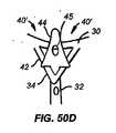
- A61F2230/0054—V-shaped
- A—HUMAN NECESSITIES
- A61—MEDICAL OR VETERINARY SCIENCE; HYGIENE
- A61F—FILTERS IMPLANTABLE INTO BLOOD VESSELS; PROSTHESES; DEVICES PROVIDING PATENCY TO, OR PREVENTING COLLAPSING OF, TUBULAR STRUCTURES OF THE BODY, e.g. STENTS; ORTHOPAEDIC, NURSING OR CONTRACEPTIVE DEVICES; FOMENTATION; TREATMENT OR PROTECTION OF EYES OR EARS; BANDAGES, DRESSINGS OR ABSORBENT PADS; FIRST-AID KITS
- A61F2230/00—Geometry of prostheses classified in groups A61F2/00 - A61F2/26 or A61F2/82 or A61F9/00 or A61F11/00 or subgroups thereof
- A61F2230/0063—Three-dimensional shapes
- A61F2230/0065—Three-dimensional shapes toroidal, e.g. ring-shaped, doughnut-shaped
- A—HUMAN NECESSITIES
- A61—MEDICAL OR VETERINARY SCIENCE; HYGIENE
- A61F—FILTERS IMPLANTABLE INTO BLOOD VESSELS; PROSTHESES; DEVICES PROVIDING PATENCY TO, OR PREVENTING COLLAPSING OF, TUBULAR STRUCTURES OF THE BODY, e.g. STENTS; ORTHOPAEDIC, NURSING OR CONTRACEPTIVE DEVICES; FOMENTATION; TREATMENT OR PROTECTION OF EYES OR EARS; BANDAGES, DRESSINGS OR ABSORBENT PADS; FIRST-AID KITS
- A61F2230/00—Geometry of prostheses classified in groups A61F2/00 - A61F2/26 or A61F2/82 or A61F9/00 or A61F11/00 or subgroups thereof
- A61F2230/0063—Three-dimensional shapes
- A61F2230/0067—Three-dimensional shapes conical
- A—HUMAN NECESSITIES
- A61—MEDICAL OR VETERINARY SCIENCE; HYGIENE
- A61F—FILTERS IMPLANTABLE INTO BLOOD VESSELS; PROSTHESES; DEVICES PROVIDING PATENCY TO, OR PREVENTING COLLAPSING OF, TUBULAR STRUCTURES OF THE BODY, e.g. STENTS; ORTHOPAEDIC, NURSING OR CONTRACEPTIVE DEVICES; FOMENTATION; TREATMENT OR PROTECTION OF EYES OR EARS; BANDAGES, DRESSINGS OR ABSORBENT PADS; FIRST-AID KITS
- A61F2230/00—Geometry of prostheses classified in groups A61F2/00 - A61F2/26 or A61F2/82 or A61F9/00 or A61F11/00 or subgroups thereof
- A61F2230/0063—Three-dimensional shapes
- A61F2230/0069—Three-dimensional shapes cylindrical
- A—HUMAN NECESSITIES
- A61—MEDICAL OR VETERINARY SCIENCE; HYGIENE
- A61F—FILTERS IMPLANTABLE INTO BLOOD VESSELS; PROSTHESES; DEVICES PROVIDING PATENCY TO, OR PREVENTING COLLAPSING OF, TUBULAR STRUCTURES OF THE BODY, e.g. STENTS; ORTHOPAEDIC, NURSING OR CONTRACEPTIVE DEVICES; FOMENTATION; TREATMENT OR PROTECTION OF EYES OR EARS; BANDAGES, DRESSINGS OR ABSORBENT PADS; FIRST-AID KITS
- A61F2230/00—Geometry of prostheses classified in groups A61F2/00 - A61F2/26 or A61F2/82 or A61F9/00 or A61F11/00 or subgroups thereof
- A61F2230/0063—Three-dimensional shapes
- A61F2230/0073—Quadric-shaped
- A61F2230/0078—Quadric-shaped hyperboloidal
- A—HUMAN NECESSITIES
- A61—MEDICAL OR VETERINARY SCIENCE; HYGIENE
- A61F—FILTERS IMPLANTABLE INTO BLOOD VESSELS; PROSTHESES; DEVICES PROVIDING PATENCY TO, OR PREVENTING COLLAPSING OF, TUBULAR STRUCTURES OF THE BODY, e.g. STENTS; ORTHOPAEDIC, NURSING OR CONTRACEPTIVE DEVICES; FOMENTATION; TREATMENT OR PROTECTION OF EYES OR EARS; BANDAGES, DRESSINGS OR ABSORBENT PADS; FIRST-AID KITS
- A61F2230/00—Geometry of prostheses classified in groups A61F2/00 - A61F2/26 or A61F2/82 or A61F9/00 or A61F11/00 or subgroups thereof
- A61F2230/0063—Three-dimensional shapes
- A61F2230/0073—Quadric-shaped
- A61F2230/008—Quadric-shaped paraboloidal
- A—HUMAN NECESSITIES
- A61—MEDICAL OR VETERINARY SCIENCE; HYGIENE
- A61F—FILTERS IMPLANTABLE INTO BLOOD VESSELS; PROSTHESES; DEVICES PROVIDING PATENCY TO, OR PREVENTING COLLAPSING OF, TUBULAR STRUCTURES OF THE BODY, e.g. STENTS; ORTHOPAEDIC, NURSING OR CONTRACEPTIVE DEVICES; FOMENTATION; TREATMENT OR PROTECTION OF EYES OR EARS; BANDAGES, DRESSINGS OR ABSORBENT PADS; FIRST-AID KITS
- A61F2250/00—Special features of prostheses classified in groups A61F2/00 - A61F2/26 or A61F2/82 or A61F9/00 or A61F11/00 or subgroups thereof
- A61F2250/0058—Additional features; Implant or prostheses properties not otherwise provided for
- A61F2250/006—Additional features; Implant or prostheses properties not otherwise provided for modular
- A—HUMAN NECESSITIES
- A61—MEDICAL OR VETERINARY SCIENCE; HYGIENE
- A61F—FILTERS IMPLANTABLE INTO BLOOD VESSELS; PROSTHESES; DEVICES PROVIDING PATENCY TO, OR PREVENTING COLLAPSING OF, TUBULAR STRUCTURES OF THE BODY, e.g. STENTS; ORTHOPAEDIC, NURSING OR CONTRACEPTIVE DEVICES; FOMENTATION; TREATMENT OR PROTECTION OF EYES OR EARS; BANDAGES, DRESSINGS OR ABSORBENT PADS; FIRST-AID KITS
- A61F2250/00—Special features of prostheses classified in groups A61F2/00 - A61F2/26 or A61F2/82 or A61F9/00 or A61F11/00 or subgroups thereof
- A61F2250/0058—Additional features; Implant or prostheses properties not otherwise provided for
- A61F2250/0069—Sealing means
Landscapes
- Health & Medical Sciences (AREA)
- Cardiology (AREA)
- Engineering & Computer Science (AREA)
- Biomedical Technology (AREA)
- Heart & Thoracic Surgery (AREA)
- Transplantation (AREA)
- Oral & Maxillofacial Surgery (AREA)
- Vascular Medicine (AREA)
- Life Sciences & Earth Sciences (AREA)
- Animal Behavior & Ethology (AREA)
- General Health & Medical Sciences (AREA)
- Public Health (AREA)
- Veterinary Medicine (AREA)
- Prostheses (AREA)
- Surgical Instruments (AREA)
Abstract
Translated fromJapaneseDescription
Translated fromJapanese本発明は心臓弁を血管内から交換するための方法及び装置に関する。より特別には、本発明は、拡張可能で且つ回収可能なアンカーを使用して血管内から心臓弁を交換弁と置換する方法及び装置に関する。 The present invention relates to a method and apparatus for exchanging a heart valve from within a blood vessel. More particularly, the present invention relates to a method and apparatus for replacing a heart valve with a replacement valve from within a blood vessel using an expandable and recoverable anchor.
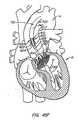
心臓外科手術は、疾患した心臓弁を修復し又は交換するために使用される。弁の外科手術は、一般的な麻酔によって行われる心臓切開処置である。患者の胸骨(胸骨切開術)によって切開が行われ、患者の心臓弁は、血流が心肺バイパス器内へと迂回されている間停止せしめられる。 Cardiac surgery is used to repair or replace a diseased heart valve. Valve surgery is an open heart procedure performed by general anesthesia. An incision is made by the patient's sternum (sternotomy) and the patient's heart valve is stopped while blood flow is diverted into the cardiopulmonary bypass device.
弁交換は、一般的に狭窄症と称される本来の心臓弁の狭窄があるとき又は本来の弁が漏れるか又は逆流するときに指示され得る。弁を交換するとき、本来の弁は、切除され且つ生物学的又は機械的な弁と交換される。機械的な弁は、血液凝固の形成を防止するために長期間の抗凝固剤を必要とし、弁の音は胸部を介して聞くことができる場合が多い。生物学的組織弁は、典型的には、このような薬剤を必要としない。組織弁は、死体から入手するか又はブタ若しくはウシのものであっても良く且つ一般的に患者の心臓に固定される合成リングに取り付けられる。 Valve replacement can be indicated when there is a stenosis of the original heart valve, commonly referred to as stenosis, or when the original valve leaks or regurgitates. When replacing the valve, the original valve is excised and replaced with a biological or mechanical valve. Mechanical valves require long-term anticoagulants to prevent the formation of blood clots, and the sound of the valves can often be heard through the chest. Biological tissue valves typically do not require such agents. The tissue valve may be obtained from a cadaver or may be porcine or bovine and is typically attached to a synthetic ring that is secured to the patient's heart.
弁交換外科手術は、著しい随伴する危険を有する侵襲性の高い手術である。危険性としては、出血、感染、脳卒中、心臓発作、不整脈、腎不全、麻酔薬の副作用ばかりでなく、外科手術中の患者の2乃至5%の死亡がある。 Valve replacement surgery is a highly invasive procedure with significant associated risks. Risks include bleeding, infection, stroke, heart attack, arrhythmia, renal failure, side effects of anesthetics, as well as death of 2-5% of patients undergoing surgery.
外科手術後、患者は、栓子及び人工心肺に関連する他のファクタにより一時的に混乱するかも知れない。手術後の最初の2乃至3日は心臓の機能を綿密に監視することができる集中治療室内で過ごす。平均的な入院期間は1乃至2週間であり、完全に回復するには数週間乃至数ヶ月が必要である。 After surgery, the patient may be temporarily confused by obturators and other factors related to cardiopulmonary bypass. The first few days after surgery are spent in an intensive care unit where heart function can be closely monitored. The average hospital stay is 1 to 2 weeks, and weeks or months are required for full recovery.
近年、最少侵襲性の外科手術及び介入心臓学の開発が幾らかの研究者に大動脈心臓弁の経皮的な交換を追求させることを促して来ている。ニュージャージ州フォートリーにあるPercutaneous Valve Techhnologies(“PVT”)は、生体人工器官弁と一体化されたバルーン拡張可能なステントを開発した。ステント/弁装置が疾患した本来の弁を横切るように配備されて弁を永久に開放状態に保持し、それによって、本来の弁を切開し且つ本来の弁の代わりに生体人工弁を配備する必要性を緩和している。PVTの装置は、X線透視ガイドを使用する局部麻酔によって心臓カテーテル検査の検査室に給送され、それによって、一般的な麻酔及び開心術を避けるように設計されている。この装置は2002年4月に最初に患者の体内に移植された。 In recent years, the development of minimally invasive surgery and interventional cardiology has prompted some researchers to pursue percutaneous replacement of the aortic heart valve. Percutaneous Valve Technologies ("PVT"), Fortley, NJ, has developed a balloon expandable stent integrated with a bioprosthetic valve. Need to deploy the stent / valve device across the diseased native valve to keep the valve permanently open, thereby dissecting the original valve and deploying a bioprosthetic valve instead of the original valve Relaxed. The PVT device is delivered to the cardiac catheterization laboratory by local anesthesia using a fluoroscopic guide, thereby avoiding common anesthesia and open heart surgery. This device was first implanted in a patient's body in April 2002.
PVTの装置は幾つかの欠点を有している。PVTのステントの配備は非可逆的であり、ステントは回収出来ない。これは重大な欠点である。なぜならば、大動脈に対して余り遠くに配備されると、患者の冠状動脈を塞ぐ危険性があるからである。更に、(大動脈から遠く且つ心室により近い)別の方向に誤配備されたステント/弁は、僧帽装置を侵し、最終的には小葉がステント/弁の端縁に対して連続的に摩擦されると小葉を摩耗させるであろう。 PVT equipment has several drawbacks. The deployment of the PVT stent is irreversible and the stent cannot be retrieved. This is a serious drawback. This is because, if deployed too far from the aorta, there is a risk of blocking the patient's coronary artery. In addition, a stent / valve misdeployed in another direction (far from the aorta and closer to the ventricle) will erode the mitral device and eventually the leaflets will be continuously rubbed against the edge of the stent / valve. This will wear the leaflets.
PVT装置の別の欠点は、その比較的大きな断面給送輪郭である。PVT装置のステント/弁結合装置は、給送バルーン上に取り付けられ、大動脈の刺激によって給送を逆行させる。従って順行性中隔横断方法が必要とされる。この方法は、処置の複雑さ及び危険性を著しく増大させる隔壁の穿刺及び僧帽弁内を通る経路を必要とする。極めて少数の心臓病専門医は、最近、それ自体が難しい処置である中隔横断穿刺を行うように訓練を受けている。 Another disadvantage of the PVT device is its relatively large cross-sectional feed profile. The stent / valve coupling device of the PVT device is mounted on a delivery balloon and reverses delivery by aortic stimulation. Therefore, an antegrade septal crossing method is needed. This method requires septal puncture and a pathway through the mitral valve that significantly increases the complexity and risk of the procedure. A very small number of cardiologists have recently been trained to perform transseptal punctures, which are themselves difficult procedures.
他の従来技術による交換心臓弁は、アンカーとして自己拡張性のステントを使用している。血管内大動脈交換処置においては、冠状動脈及び僧帽弁に対する大動脈弁の正確な配備が重要である。しかしながら、標準的な自己拡張性の装置は、配備の正確さが極めて低い。ステントの基端は、正しい配備がX線透視によって実証されるまで給送装置から外されないことが多く、ステントは、典型的にはひとたび取り外されると飛び跳ねる。従って、ステントの端部が本来の弁、冠状動脈及び僧帽弁に対してどこにあるかを知ることが不可能である場合が多い。 Other prior art exchange heart valves use self-expanding stents as anchors. In endovascular aortic replacement procedures, accurate deployment of the aortic valve relative to the coronary and mitral valves is important. However, standard self-expanding devices have very low deployment accuracy. The proximal end of the stent is often not removed from the delivery device until proper deployment is demonstrated by fluoroscopy, and the stent typically jumps once removed. Thus, it is often impossible to know where the end of the stent is relative to the native valve, coronary artery and mitral valve.
更に、新しい弁が最終的な配備に先立って機能している様子を視認できることは極めて望ましい。しかしながら、最終的で且つ非可逆的な配備に先立つ視認は、標準的な自己拡張装置によって行うことが出来ず、交換弁は、最終的な配備前には十分に機能しないことが多い。 Furthermore, it is highly desirable to be able to see how the new valve is functioning prior to final deployment. However, visual recognition prior to final and irreversible deployment cannot be performed by standard self-expanding devices, and replacement valves often do not function well prior to final deployment.
従来技術による自己拡張性交換心臓弁装置の別の欠点は、径方向の強度の欠如である。自己拡張性の装置が給送シースによって容易に給送されるためには、金属は、塑性変形されることなく給送カテーテルの内側で撓み且つ曲がることが必要である。動脈ステントにおいては、これは難しいことではなく、血管壁に対して適切な径方向の力をかけ且つ塑性変形させることなく給送カテーテルの内側に嵌合するように十分に小さな直径まで圧潰させることができる多くの市販の動脈ステントが存在する。 Another disadvantage of prior art self-expanding exchange heart valve devices is the lack of radial strength. In order for a self-expanding device to be easily delivered by a delivery sheath, the metal needs to bend and bend inside the delivery catheter without being plastically deformed. In arterial stents, this is not difficult, with appropriate radial force applied to the vessel wall and collapse to a sufficiently small diameter to fit inside the delivery catheter without plastic deformation. There are many commercially available arterial stents that can.
しかしながら、ステントが大動脈弁の交換の場合のように内側に締結された弁を有する場合には、血管壁に対するステントの固定は、心拡張期に心室の内側へ戻るのを防止するための力は、ステント/血管壁境界部に直接伝えられる。従って、自己拡張性のステント/弁を血管壁と接触状態に保ち且つ滑らないように保つのに必要とされる径方向の力の量は、内側に弁を備えていないステントにおけるよりも遙かに大きい。更に、十分な径方向の力を有しない自己拡張性ステントは、心臓の鼓動毎に拡張及び収縮を終え、それによって、弁を変形させ、弁の機能に影響を及ぼし、移動し、恐らく完全に外れるであろう。自己拡張性ステントの突っ張りの厚みを単に厚くすることは、自己拡張性ステントのより大きな断面及び/又は塑性変形の危険性を生じるので実用的な解決方法ではない。 However, if the stent has an internally clamped valve as in the case of an aortic valve replacement, the fixation of the stent to the vessel wall is not enough to prevent it from returning inside the ventricle during diastole. Directly to the stent / vessel wall interface. Thus, the amount of radial force required to keep a self-expanding stent / valve in contact with the vessel wall and not slip is much greater than in a stent without an internal valve. Big. Furthermore, self-expanding stents that do not have sufficient radial force will finish expanding and contracting with each heart beat, thereby deforming the valve, affecting the function of the valve, moving, and possibly completely It will come off. Simply increasing the thickness of the self-expanding stent is not a practical solution because it creates a larger cross-section and / or risk of plastic deformation of the self-expanding stent.
Garrisonらに付与された米国特許第2002/0151970号は、患者の大動脈を介して給送できるようになされた大動脈弁の交換のための二部品からなる装置を記載している。ステントは血管内から本来の弁を横切るように配置され、次いで、ステントの内腔内に交換弁が配備される。給送中に、ステントと弁とを分離することによって、当該装置における給送装置の断面は、中隔横断方法を必要とすることなく大動脈を介する給送を可能にするように十分に小さくすることができる。ステントと交換弁のフレームとの両方ともがバルーン拡張可能であるか又は自己拡張性とすることができる。 US 2002/0151970 to Garrison et al. Describes a two-part device for replacement of an aortic valve that is adapted to be delivered through a patient's aorta. The stent is placed across the native valve from within the vessel, and then a replacement valve is deployed within the stent lumen. By separating the stent and the valve during delivery, the cross section of the delivery device in the device is sufficiently small to allow delivery through the aorta without the need for a septal crossing method. be able to. Both the stent and the exchange valve frame can be balloon expandable or self-expandable.
Garrisonの特許出願に記載された装置は、大動脈方法を提供するけれども幾つかの欠点を有している。第一に、この装置のステント部分は、給送中のステントの動力学的な再配置を妨げる第一の部品として一つの段階において本来の弁を横切るように給送される。拡張中のステントの短縮又は進入は不適切な整合につながるかも知れない。 Although the device described in the Garrison patent application provides an aortic method, it has several drawbacks. First, the stent portion of the device is fed across the original valve in one stage as a first part that prevents dynamic repositioning of the stent during delivery. Shortening or entering the stent during expansion may lead to improper alignment.
更に、Garrisonのステントは、単に本来の弁の小葉を心臓の壁に対して圧潰させ且つ弁の本来の位置に対する当該装置の確実な整合を提供する方法で小葉と係合しない。このことは、冠状動脈口を閉塞するという同時に発生する虞をも増大させるばかりでなく、移植後の装置の長期の移動の虞をも増大させる。更に、ステントは、交換弁が給送後に定置される穴又は空隙を含んでいる。組織がこれらの空隙から突出してステント内での弁の不適切な定置の虞を増大させるかも知れない。 Furthermore, the Garrison stent simply does not engage the leaflets in a manner that crushes the original leaflets of the valve against the heart wall and provides positive alignment of the device relative to the original position of the valve. This not only increases the risk of simultaneous occlusion of the coronary ostium, but also increases the risk of long-term movement of the device after implantation. In addition, the stent includes a hole or void in which the exchange valve is placed after delivery. Tissue may protrude from these voids and increase the risk of improper placement of the valve within the stent.
心臓弁を血管内から交換するための既知の技術に伴う欠点に鑑み、これらの欠点を解消する方法及び装置を提供するのが望ましい。 In view of the disadvantages associated with known techniques for exchanging heart valves from within a blood vessel, it would be desirable to provide a method and apparatus that overcomes these disadvantages.
本発明の一つの特徴によって、患者の心臓弁を血管内から交換する方法が提供される。幾つかの実施形態においては、当該方法は、交換弁と拡張可能なアンカーとを血管内から非拡張状態で心臓弁の近くへ給送するステップと、アンカーをアンカー部位においてアンカーが組織と接触する配備形状へ拡張させるステップと、アンカーをアンカー部位に再配備するステップと、アンカーをアンカー部位に配備するステップとを含んでいる。前記再配備ステップは、より細かく再配備するためにアンカーを収縮させ且つアンカー部位で再拡張させるステップを含んでいても良い。外部からの非液圧又は非空気圧の作動力を適用するステップを含んでいても良い。 According to one aspect of the present invention, a method is provided for exchanging a patient's heart valve from within a blood vessel. In some embodiments, the method includes delivering the exchange valve and the expandable anchor from within the blood vessel in an unexpanded state to the vicinity of the heart valve; and the anchor contacts the tissue at the anchor site. Expanding the deployed shape; redeploying the anchor at the anchor site; and deploying the anchor at the anchor site. The redeployment step may include retracting the anchor and re-expanding at the anchor site for finer redeployment. A step of applying an external non-hydraulic or non-pneumatic actuation force may be included.
本発明の別の特徴においては、患者の心臓弁を血管内から交換するための方法が提供される。幾つかの実施形態においては、当該方法は、交換弁と拡張可能なアンカーを拡張させない形状で心臓弁の近くに血管内から又は経皮的に給送するステップと、アンカーを当該アンカーが第一のアンカー部位において組織と接触する配置形状へ拡張させるステップと、アンカーを第二のアンカー部位に再位置決めするステップと、アンカーを第二のアンカー部位に配備するステップとを含んでいる。前記再位置決めするステップは、アンカーを収縮させ且つアンカーを第二のアンカー部位で再度拡張させるステップを含んでいても良い。収縮ステップは、アンカーに外部からの非液圧又は非空気圧の作動力を適用するステップを含んでいても良い。 In another aspect of the invention, a method for replacing a patient's heart valve from within a blood vessel is provided. In some embodiments, the method includes delivering the exchange valve and the expandable anchor in an unexpandable configuration from the blood vessel near the heart valve or percutaneously; Expanding to an arrangement configuration in contact with tissue at the anchor site, repositioning the anchor at the second anchor site, and deploying the anchor at the second anchor site. The repositioning step may include retracting the anchor and re-expanding the anchor at the second anchor site. The contraction step may include applying an external non-hydraulic or non-pneumatic actuation force to the anchor.
幾つかの実施形態においては、配備ステップは、アンカーを配備器具から取り外すステップを含んでいる。給送ステップは、アンカーに結合された又はアンカーから分離された交換心臓弁を給送するステップを含んでいても良く、この場合には、当該方法は、交換弁をアンカーに取り付けるステップを更に含んでいる。 In some embodiments, the deploying step includes removing the anchor from the deployment device. The delivering step may include delivering an exchange heart valve coupled to or separated from the anchor, in which case the method further includes attaching the exchange valve to the anchor. It is out.
心臓弁が大動脈弁である場合には、給送ステップは、拡張可能なアンカー及び交換弁を逆行方法によって大動脈弁の近くへ血管内から又は経皮的に給送するステップを含んでいても良い。 If the heart valve is an aortic valve, the delivering step may include delivering the expandable anchor and exchange valve from within the vessel or percutaneously to the aortic valve in a retrograde manner. .
幾つかの実施形態においては、配備ステップはアンカー内でバルーンを拡張させるステップを含んでいても良く、幾つかの実施形態においては、配備ステップは、アンカーを係止形状に係止するステップを含んでいても良い。アンカーの基端及び末端領域は別個に拡張されても良い。 In some embodiments, the deploying step may include expanding the balloon within the anchor, and in some embodiments, the deploying step includes locking the anchor in a locking shape. You can leave. The proximal and distal regions of the anchor may be expanded separately.
本発明はまた、アンカーを配備する前に少なくとも基端又は末端方向へのアンカーの動きに抗するために例えば心臓弁の組織と接触することによって、アンカーを第一及び第二のアンカー部位と整合させるステップをも含んでいても良い。 The present invention also aligns the anchor with the first and second anchor sites, for example by contacting the tissue of the heart valve to resist anchor movement at least proximally or distally before deploying the anchor. It may also include a step of causing
本発明のもう一つ別の特徴は、患者の心臓弁を経皮的に交換する方法を提供する。当該方法は、交換弁及び拡張可能なアンカーを非拡張形状で心臓弁の近くへ経皮的に給送するステップと、アンカーを当該アンカーがアンカー部位において組織と接触する拡張形状へと拡張させるステップと、アンカーを配備器具から取り外すステップとを含んでいる。交換弁は、アンカーに結合して又はアンカーとは別個に給送しても良く、この場合には、この方法はまた、弁をアンカーに取り付けるステップをも含んでいる。 Another feature of the present invention provides a method for percutaneously replacing a patient's heart valve. The method includes the steps of percutaneously delivering an exchange valve and an expandable anchor in a non-expanded configuration near a heart valve and expanding the anchor to an expanded configuration where the anchor contacts tissue at the anchor site. And removing the anchor from the deployment device. The exchange valve may be coupled to the anchor or delivered separately from the anchor, in which case the method also includes the step of attaching the valve to the anchor.
幾つかの実施形態においては、当該方法は更に、観察ステップの後で且つ取り外しステップの前に、アンカーを第二のアンカー部位へ再位置決めするステップを更に含んでいる。幾つかの実施形態においては、拡張ステップは、アンカーに外部からの非液圧又は非空気圧の作動力をかけるステップを含んでおり、幾つかの実施形態においては、当該方法は更に、観察ステップ後にアンカー内でバルーンを拡張させるステップを含んでいる。当該方法は、アンカーをアンカー部位と整合させるステップを含んでいても良い。 In some embodiments, the method further includes repositioning the anchor to the second anchor site after the observation step and before the removal step. In some embodiments, the expanding step includes applying an external non-hydraulic or non-pneumatic actuation force to the anchor, and in some embodiments, the method further includes after the observing step. Expanding the balloon within the anchor. The method may include aligning the anchor with the anchor site.
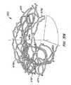
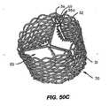
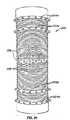
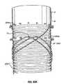
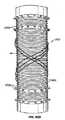
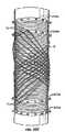
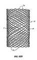
本発明の一つの特徴は、患者の本来の心臓弁を血管内から交換する装置を提供する。この装置は、拡張可能な編物を備えているアンカーと、患者の体内に固定されるようになされた交換弁とを含んでいる。幾つかの実施形態においては、アンカーの拡張可能な編物は単一ストランドのワイヤによって作られる。幾つかの実施形態においては、拡張可能な編物は少なくとも1つの端縁構造を含んでいる。アンカーと交換弁とは、血管内からの給送及び配置ができる構造とされるのが好ましい。 One aspect of the present invention provides an apparatus for exchanging a patient's original heart valve from within a blood vessel. The device includes an anchor having an expandable knitted fabric and a replacement valve adapted to be secured within the patient's body. In some embodiments, the expandable braid of the anchor is made with a single strand of wire. In some embodiments, the expandable knitted fabric includes at least one edge structure. The anchor and the exchange valve are preferably structured so that they can be fed and placed from within the blood vessel.
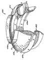
本発明は、患者の本来の心臓弁を交換するための装置に関する。この装置は、血管内から給送するようになされた拡張可能な編物を有しているアンカーを含んでいる。アンカーは更に、本来の弁のアンカー部位における能動的な短縮によって拡張するようになされている。この装置はまた、患者の体内に固定されるようになされている交換弁をも含んでいる。幾つかの実施形態においては、アンカーの編物は更に、中心軸線に向かってほぼ径方向内方に向けられた0.5atm又は2atmまでの圧力に応答して実質的に変形しないままとされている。幾つかの実施形態においては、アンカーブレードは、アンカーが拡張されたときに第一の領域の直径よりも大きな直径を有する第一の領域及び第二の領域を含んでいる。幾つかの実施形態においては、アンカーの編物は、径方向に対称であるか、左右対称であるか又は非対称である拡張形状を有する構造とされている。幾つかの実施形態においては、アンカーは、第一及び第二のワイヤを含んでおり、第一のワイヤの直径は第二のワイヤの直径より小さい。幾つかの実施形態においては、アンカーは、異なる材料によって作られた第一及び第二のワイヤを含んでいる。幾つかの実施形態においては、アンカーは圧潰された給送形状、定置形状及び拡張された配備形状を有している。 The present invention relates to an apparatus for replacing a patient's native heart valve. The device includes an anchor having an expandable knitted fabric adapted for delivery from within a blood vessel. The anchor is further adapted to expand by active shortening at the native valve anchor site. The device also includes an exchange valve adapted to be secured within the patient's body. In some embodiments, the anchor braid is further left substantially undeformed in response to pressures up to 0.5 atm or 2 atm directed generally radially inward toward the central axis. . In some embodiments, the anchor blade includes a first region and a second region having a diameter that is greater than the diameter of the first region when the anchor is expanded. In some embodiments, the anchor knitted fabric is structured to have an expanded shape that is radially symmetric, bilaterally symmetric, or asymmetric. In some embodiments, the anchor includes first and second wires, and the diameter of the first wire is less than the diameter of the second wire. In some embodiments, the anchor includes first and second wires made of different materials. In some embodiments, the anchor has a collapsed delivery shape, a stationary shape, and an expanded deployment shape.
幾つかの実施形態においては、当該装置は更に、編物の拡張を維持する構造とされた1つの又は複数の係止部材を含んでいる。幾つかの実施形態においては、更に、交換弁をアンカー内に支持するようになされた弁支持部材を含んでいる。幾つかの実施形態においては、アンカーは、末端に末端配備装置境界部を含んでおり、この末端配備装置境界部は、配備装置がアンカーの末端に基端方向の力をかけるのを許容するようになされている。幾つかの実施形態においては、アンカーは、基端に基端配備装置境界部を含んでおり、この基端配備装置境界部は、配備装置がアンカーの基端に末端方向の力をかけるのを許容するようになされている。 In some embodiments, the device further includes one or more locking members configured to maintain expansion of the knitted fabric. Some embodiments further include a valve support member adapted to support the exchange valve within the anchor. In some embodiments, the anchor includes a distal deployer boundary at the distal end that allows the deployer to apply a proximal force to the distal end of the anchor. Has been made. In some embodiments, the anchor includes a proximal deployer boundary at the proximal end that prevents the deployer from applying a distal force to the proximal end of the anchor. It is made to allow.
本発明の一つの特徴は、本来の大動脈弁を交換するための方法を提供する。このような方法は、交換弁と拡張可能な編物を有しているアンカーとを血管内から給送することを含んでいる。本来の大動脈弁内の部位への給送が行われるのが好ましい。給送は、アンカーを能動的に短縮させてアンカーを径方向へ拡張させて拡張形状としてアンカー部位に固定することによって行われるのが好ましい。幾つかの実施形態においては、当該方法は、アンカーを拡張形状に係止するステップを含んでいる。幾つかの実施形態においては、当該方法は、アンカーの第一の領域を第一の直径まで拡張させ、アンカーの第二の領域を前記第一の直径よりも大きい第二の直径まで拡張させることを含んでいる。 One aspect of the present invention provides a method for replacing a native aortic valve. Such a method involves delivering an exchange valve and an anchor having an expandable knitted fabric from within the blood vessel. Preferably, delivery to the site within the original aortic valve is performed. The feeding is preferably performed by actively shortening the anchor and expanding the anchor in the radial direction to fix the anchor in an expanded shape. In some embodiments, the method includes locking the anchor in an expanded shape. In some embodiments, the method expands the first region of the anchor to a first diameter and expands the second region of the anchor to a second diameter that is greater than the first diameter. Is included.
幾つかの実施形態においては、当該方法の短縮ステップは、僧帽弁との干渉を避けながら、アンカーを径方向に拡張させてアンカー部位に固定するために能動的に短縮させることを含んでいる。幾つかの実施形態においては、短縮させるステップは、アンカーを能動的に短縮させて径方向に対称形状、左右対称な拡張形状又は非対称形状へと拡張させることを含んでいる。 In some embodiments, the shortening step of the method includes actively shortening the anchor to radially expand and secure to the anchor site while avoiding interference with the mitral valve. . In some embodiments, the step of shortening includes actively shortening the anchor to expand into a radially symmetric shape, a bilaterally expanded shape, or an asymmetric shape.
幾つかの実施形態においては、アンカーは、前記短縮ステップに先立って自己拡張せしめられる。幾つかの実施形態においては、短縮ステップは、アンカーの基端又は末端において配備装置の境界部に基端方向の力をかけることを含んでいる。幾つかの実施形態においては、短縮ステップは、アンカーの基端で配備装置の境界部に末端方向の力をかけることを含んでいる。 In some embodiments, the anchor is self-expanding prior to the shortening step. In some embodiments, the shortening step includes applying a proximal force to the deployment device boundary at the proximal or distal end of the anchor. In some embodiments, the shortening step includes applying a distal force to the deployment device boundary at the proximal end of the anchor.
幾つかの実施形態においては、給送長さは約15mm乃至約150mmであり、配備長さは約5mm乃至約40mmである。幾つかの実施形態においては、当該装置は、約0.05乃至約0.5、約0.1乃至約0.35又は約0.15乃至約0.25の配備長さら対する給送長さの比を有している。幾つかの実施形態においては、当該装置は、定置形状を有しているアンカーを含んでおり、前記アンカーは、定置形状において硬化せしめられる形状記憶材料を含んでいる。定置形状は、給送長さと配備長さとの間の長さを有することができる。 In some embodiments, the feed length is about 15 mm to about 150 mm and the deployed length is about 5 mm to about 40 mm. In some embodiments, the device has a delivery length of about 0.05 to about 0.5, about 0.1 to about 0.35, or about 0.15 to about 0.25 deployment length. The ratio of In some embodiments, the device includes an anchor having a stationary shape, the anchor including a shape memory material that is cured in the stationary shape. The stationary shape can have a length between the feed length and the deployed length.
幾つかの実施形態においては、当該装置は、血管内からの配備中に能動的に短縮する形状とされているアンカーを含んでいる。当該装置はまた、アンカーの拡張を維持する構造とされた1又は複数の係止部材をも含んでいても良い。係止部材はまた、アンカーの拡張を複数の拡張量に維持して装置に非円筒形形状を付与する構造とされていても良い。 In some embodiments, the device includes an anchor configured to actively shorten during deployment from within a blood vessel. The device may also include one or more locking members configured to maintain anchor expansion. The locking member may also be configured to provide a non-cylindrical shape to the device while maintaining the expansion of the anchor at multiple expansion amounts.
実施形態のうちのいずれにおいても、装置は更にアンカー内に交換弁を支持するようになされた弁支持部材を更に含んでいても良い。弁支持部材はまた、弁支持部材の伸長部である係止部材をも含んでいても良い。 In any of the embodiments, the device may further include a valve support member adapted to support the exchange valve within the anchor. The valve support member may also include a locking member that is an extension of the valve support member.
実施形態のいずれにおいても、装置は、アンカーの末端に設けられた末端配備装置境界部を含んでいても良く、末端の配備装置境界部は、配備装置がアンカーの末端に基端方向の力をかけるのを可能にするようになされている。末端の配備装置境界部は更に、アンカーの末端に基端方向の力をかけている間に径方向に拡張するようになされていても良い。末端の配備装置境界部は更に、配備装置が交換弁の中心穴内に配備装置のどの部分も通過させることなく、アンカーの末端に基端方向の力をかけるのを許容するようになされていても良い。 In any of the embodiments, the device may include a distal deployment device boundary provided at the distal end of the anchor, where the distal deployment device boundary causes the deployment device to exert a proximal force on the distal end of the anchor. It is designed to make it possible to apply. The distal deployer interface may further be adapted to expand radially while applying a proximal force to the distal end of the anchor. The distal deployer interface may further be adapted to allow the deployer to apply a proximal force to the distal end of the anchor without passing any part of the deployer through the central hole of the exchange valve. good.
幾つかの実施形態においては、当該装置はアンカーを含むことができ、当該アンカーは、アンカーの基端に基端配備装置境界部を含んでおり、当該基端配備装置境界部は、配備装置がアンカーの基端に末端方向の力をかけるのを許容するようになされている。基端の配備装置境界部は更に、アンカーの基端に末端方向の力をかけている間に径方向に拡張するようになされていても良い。基端の配備装置境界部は更に、配備装置が複数の配備装置の指状部材を介してアンカーの基端に末端方向の力をかけるのを許容するようになされている。 In some embodiments, the device can include an anchor, the anchor including a proximal deployment device boundary at a proximal end of the anchor, wherein the proximal deployment device boundary is defined by the deployment device. It is adapted to allow a distal force to be applied to the proximal end of the anchor. The proximal deployment device boundary may further be adapted to expand radially while applying a distal force to the proximal end of the anchor. The proximal deployment device boundary is further adapted to allow the deployment device to apply a distal force to the proximal end of the anchor via the plurality of deployment device fingers.
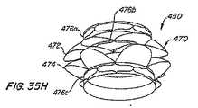
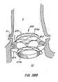
本発明は、患者の心臓弁を血管内から交換するための装置及び方法を提供する。本発明の一つの特徴により、縁領域及び裾領域を備えた拡張可能なアンカーと、前記縁領域及び裾領域が心臓弁の小葉と係合するために経皮的に拡張(例えば、独立の拡張又は同時拡張)させるような構造とされている交換弁とを含んでいる装置が提供される。縁領域及び/又は裾領域は、配備及び拡張後に装置が進入するのを阻止するようになされていても良い。アンカー及び交換弁の拡張は、バルーンの膨張、自己拡張及びこれらの組み合わせによって行っても良い。拡張を維持するために係止部材を設けても良い。 The present invention provides an apparatus and method for exchanging a patient's heart valve from within a blood vessel. In accordance with one aspect of the present invention, an expandable anchor with an edge region and a skirt region, and the edge region and the skirt region expand percutaneously to engage a leaflet of a heart valve (eg, independent expansion). Or an exchange valve that is structured to be expanded simultaneously. The edge region and / or hem region may be adapted to prevent the device from entering after deployment and expansion. The expansion of the anchor and the exchange valve may be performed by balloon inflation, self-expansion and combinations thereof. A locking member may be provided to maintain expansion.
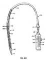
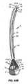
本発明はまた、血管内から心臓弁を交換し且つ幾つかの実施形態においては装置を回収するために装置を配備し且つ拡張させる助けとなる給送装置をも含んでいる。 The present invention also includes a delivery device that assists in deploying and expanding the device to replace the heart valve from within the vessel and in some embodiments retrieve the device.
本発明の別の特徴によれば、血管内から患者の心臓弁を交換するための方法が提供される。幾つかの実施形態においては、この方法は、縁領域及び裾領域を有しているアンカーと圧潰された形状でアンカーに結合された交換弁とを備えた装置を血管内から心臓弁近くへ給送するステップと、心臓弁の小葉がアンカーの縁領域と裾領域との間に捕捉されるように前記装置を拡張させるステップとを含んでいる。当該方法における拡張ステップは、小葉を捕捉する前に装置を心臓弁に対して動力学的に再位置決めするステップを含んでいても良い。拡張ステップはまた、縁領域又は裾領域を拡張させて、心臓弁を拡張した縁領域又は裾領域と確実に係合させ、次いで、拡張していない領域を拡張させる。当該装置は、回収し、再位置決めし且つ再配備することができ、当該装置は拡張形状に係止することができる。 According to another aspect of the invention, a method is provided for replacing a patient's heart valve from within a blood vessel. In some embodiments, the method provides a device comprising an anchor having an edge region and a skirt region and a replacement valve coupled to the anchor in a collapsed shape from within the vessel to near the heart valve. Delivering and expanding the device so that the leaflets of the heart valve are captured between the edge region and the skirt region of the anchor. The expansion step in the method may include the step of dynamically repositioning the device relative to the heart valve prior to capturing the leaflets. The expansion step also expands the edge region or skirt region to ensure engagement of the heart valve with the expanded edge region or skirt region, and then expands the unexpanded region. The device can be retrieved, repositioned and redeployed, and the device can be locked into an expanded configuration.
本発明の一つの特徴に従って、患者の心臓弁を血管内から交換する装置が提供される。当該装置は、拡張可能なアンカーと交換弁とを含んでおり、これらの両方が経皮的給送及び配備できるようになされている。拡張可能なアンカーは更に、患者の心臓弁の小葉と係合するための小葉係合部材を基端に有している。小葉係合部材が係合せしめられると、アンカーは、患者の冠状動脈口のほぼ末端側に位置する。更に、小葉係合部材は、ひとたび係合するとアンカーの末端方向の動きを防止する。幾つかの実施形態においては、小葉係合部材は、(特にアンカーがアンカーブレードであるときに)アンカー又はアンカーの一部分と一体にされる。他の実施形態においては、小葉係合部材はアンカーの基端に取り付けられている。ここでは、実施形態のいずれにおいても、アンカーは配備中に能動的な短縮がなされるようにすることができる。能動的な短縮は、アンカーの基端及び/又は末端の作動部材を作動させることによって生じる。アンカーはまた、係止することができるか又は係止部材を含んでいても良い。当該装置の交換弁は、アンカー内に配置され且つ配備中及び配備後において、血流を許容し且つ血液の逆流を阻止するようになされている。 In accordance with one aspect of the present invention, an apparatus is provided for exchanging a patient's heart valve from within a blood vessel. The device includes an expandable anchor and a replacement valve, both of which can be percutaneously delivered and deployed. The expandable anchor further has a leaflet engaging member at the proximal end for engaging the leaflet of the patient's heart valve. When the leaflet engaging member is engaged, the anchor is positioned approximately distal to the patient's coronary ostia. Further, the leaflet engaging member prevents distal movement of the anchor once engaged. In some embodiments, the leaflet engaging member is integral with the anchor or a portion of the anchor (especially when the anchor is an anchor blade). In other embodiments, the leaflet engaging member is attached to the proximal end of the anchor. Here, in any of the embodiments, the anchor can be actively shortened during deployment. Active shortening occurs by actuating the proximal and / or distal actuation members of the anchor. The anchor can also be locked or can include a locking member. The replacement valve of the device is positioned within the anchor and is adapted to permit blood flow and prevent blood backflow during and after deployment.
本発明のもう一つ別の特徴に従って、血管内から患者の心臓弁を交換する方法が提供される。幾つかの実施形態においては、当該方法は、基端に小葉係合部材を含んでいるアンカーとアンカー内に支持されている交換弁とを圧潰された給送形状で血管内から心臓弁の近くまで給送するステップと、アンカーを拡張させるステップと、小葉係合部材を本来の小葉と係合させるステップとを含んでいても良い。能動的な短縮は、アンカーの基端及び/又は末端作動部材を起動させるステップを含むことができる。この方法はまた、アンカーが配備位置とされた後に当該アンカーを係止するステップをも含むことができる。幾つかの実施形態においては、アンカーが患者の心臓に係合すると、当該アンカーは冠状動脈口のほぼ末端側に位置する。ここに示す実施形態のいずれにおいても、小葉係合部材は、アンカーが基端において末端方向に進入するのを阻止する。 In accordance with another aspect of the present invention, a method for replacing a patient's heart valve from within a blood vessel is provided. In some embodiments, the method includes an anchor that includes a leaflet engaging member at the proximal end and a replacement valve supported within the anchor in a collapsed delivery configuration from within the vessel and near the heart valve. And the step of expanding the anchor, and the step of engaging the leaflet engaging member with the original leaflet. Active shortening can include activating the proximal and / or distal actuation members of the anchor. The method can also include locking the anchor after it is in the deployed position. In some embodiments, when the anchor engages the patient's heart, the anchor is located approximately distal to the coronary ostium. In any of the illustrated embodiments, the leaflet engagement member prevents the anchor from entering distally at the proximal end.
本発明の一つの特徴に従って、患者の心臓弁を血管内から交換するための装置が提供される。この装置は、拡張可能なアンカーと交換弁とを含んでおり、これらは両方とも経皮的に給送及び配備出来るようになされている。拡張可能なアンカーは更に、患者の心臓弁の小葉と係合するための小葉係合部材を基端に含んでいる。小葉係合部材が係合せしめられると、アンカーは、ほぼ患者の冠状動脈口の末端側に位置する。更に、この係合がひとたび生じると、小葉係合部材はアンカーの末端方向の動きを阻止する。幾つかの実施形態においては、小葉係合部材は、アンカー又は(特に、アンカーがアンカーブレードである場合には)アンカーの一部分と一体化される。他の実施形態においては、小葉係合部材はアンカーの基端に取り付けられる。ここでは、実施形態のいずれにおいても、アンカーは、配備中に能動的な短縮がなされるようにしても良い。能動的な短縮は、アンカーの基端及び/又は末端の作動部材を作動させることによって生じる。アンカーはまた、係止することができるか又は係止部材を含んでいても良い。当該装置の交換弁は、アンカー内に配置され且つ配備中及び配備後において、血流を許容し且つ血液の逆流を阻止するようになされている。 In accordance with one aspect of the present invention, an apparatus is provided for exchanging a patient's heart valve from within a blood vessel. The device includes an expandable anchor and a replacement valve, both of which are adapted to be delivered and deployed percutaneously. The expandable anchor further includes a leaflet engaging member at the proximal end for engaging the leaflet of the patient's heart valve. When the leaflet engaging member is engaged, the anchor is located approximately distal to the patient's coronary ostia. Further, once this engagement occurs, the leaflet engagement member prevents distal movement of the anchor. In some embodiments, the leaflet engaging member is integral with the anchor or a portion of the anchor (especially when the anchor is an anchor blade). In other embodiments, the leaflet engaging member is attached to the proximal end of the anchor. Here, in any of the embodiments, the anchor may be actively shortened during deployment. Active shortening occurs by actuating the proximal and / or distal actuation members of the anchor. The anchor can also be locked or can include a locking member. The replacement valve of the device is positioned within the anchor and is adapted to permit blood flow and prevent blood backflow during and after deployment.
本発明のもう一つ別の特徴に従って、血管内から患者の心臓弁を交換する方法が提供される。幾つかの実施形態においては、当該方法は、基端に小葉係合部材を含んでいるアンカーとアンカー内に支持されている交換弁とを圧潰された給送形状で血管内から心臓弁の近くまで給送するステップと、アンカーを拡張させるステップと、小葉係合部材を本来の小葉と係合させるステップとを含んでいても良い。能動的な短縮は、アンカーの基端及び/又は末端作動部材を起動させるステップを含むことができる。この方法はまた、アンカーが配備位置とされた後に当該アンカーを係止するステップをも含むことができる。幾つかの実施形態においては、アンカーが患者の心臓に係合すると、当該アンカーは冠状動脈口のほぼ末端側に位置する。ここに示す実施形態のいずれにおいても、小葉係合部材は、アンカーが基端において末端方向に進入するのを阻止する。 In accordance with another aspect of the present invention, a method for replacing a patient's heart valve from within a blood vessel is provided. In some embodiments, the method includes an anchor that includes a leaflet engaging member at the proximal end and a replacement valve supported within the anchor in a collapsed delivery configuration from within the vessel and near the heart valve. And the step of expanding the anchor, and the step of engaging the leaflet engaging member with the original leaflet. Active shortening can include activating the proximal and / or distal actuation members of the anchor. The method can also include locking the anchor after it is in the deployed position. In some embodiments, when the anchor engages the patient's heart, the anchor is located approximately distal to the coronary ostium. In any of the illustrated embodiments, the leaflet engagement member prevents the anchor from entering distally at the proximal end.
本発明は、患者の心臓弁を血管内から交換するための方法及び装置を含んでいる。本発明の一つの特徴により、交換弁と拡張可能なアンカーとを非拡張状態で血管内から心臓弁の近くまで給送するステップと、例えばアンカー又はアンカーの一部分を拡張させ或いは収縮させるために解除可能な配備器具を使用してアンカーに基端方向及び/又は末端方向の力をかけることによってアンカーの形状を変えるために外部からの非液圧又は非空気圧作動力を適用するステップとを含んでいる。当該方法はまた、例えばバルーンを拡張させることによってアンカー内のバルーンを拡張させることを含んでいる径方向外方への力を適用するステップをも含んでいても良い。アンカーは、拡張形状に係止することができる。 The present invention includes a method and apparatus for exchanging a patient's heart valve from within a blood vessel. According to one aspect of the present invention, the exchange valve and expandable anchor are delivered in an unexpanded state from within the vessel to near the heart valve and released, for example, to expand or contract the anchor or a portion of the anchor. Applying an external non-hydraulic or non-pneumatic actuation force to change the shape of the anchor by applying a proximal and / or distal force to the anchor using a possible deployment device. Yes. The method may also include applying a radially outward force including expanding the balloon in the anchor, for example by expanding the balloon. The anchor can be locked to the expanded shape.
当該方法の幾つかの実施形態は、アンカーをアンカー位置にある解剖学的境界標識と整合させるステップと、アンカーの配備に先立ってアンカーの少なくとも基端又は末端方向の動きに抗するために、例えば心臓弁の組織(例えば、本来の弁小葉)と接触することによって、アンカーをアンカー位置に配備するステップとを含んでいても良い。 Some embodiments of the method may include aligning the anchor with an anatomical boundary marker at the anchor location and resisting at least proximal or distal movement of the anchor prior to anchor deployment, e.g. Deploying the anchor at the anchor location by contacting the heart valve tissue (eg, the native valve leaflet).
本発明のもう一つ別の特徴に従って、血管内から患者の心臓弁を交換する装置が提供され、この装置は、交換弁と、アンカーと、アンカーの領域を拡張させ又は収縮させるために基端方向又は末端方向の力のようなアンカーを再整形するためにアンカーに非液圧又は非空気圧の作動力をかけるようになされた配備器具とを含んでいる。アンカーを配備形状に係止するためにアンカー係止部材を設けても良く、外部から患者を操作できる係止部材が存在していても良い。 In accordance with another aspect of the present invention, an apparatus is provided for exchanging a patient's heart valve from within a blood vessel, the apparatus comprising a proximal end for expanding or contracting the exchange valve, the anchor, and the area of the anchor. And a deployment device adapted to apply a non-hydraulic or non-pneumatic actuation force to the anchor to reshape the anchor, such as a directional or distal force. An anchor locking member may be provided to lock the anchor in the deployed shape, and there may be a locking member capable of operating the patient from the outside.
当該装置はまた、例えば心臓弁の少なくとも一部分を閉じ込めるためにアンカーから径方向外方へ延びるようになされた整合部材を含んでいても良い。 The device may also include an alignment member adapted to extend radially outward from the anchor, for example to confine at least a portion of the heart valve.
本発明のもう一つ別の特徴に従って、血管内から患者の心臓弁を交換するための装置が提供され、当該装置は、圧潰された給送形状及び拡張された配備形状を有しているアンカーと、アンカーに結合された交換弁とを含み、前記アンカーは、付与された短縮により圧潰された給送形状と比較して拡張された配備形状で高い径方向の強度を有している。当該装置は、付与された収縮を維持するための係止機構を含んでいても良く、係止機構の作動に先立って回収できる構造とされていても良い。当該装置はまた、アンカーの経皮的な給送、配備及び収縮のための構造とされている給送装置をも含んでいても良い。 In accordance with another aspect of the present invention, there is provided an apparatus for exchanging a patient's heart valve from within a blood vessel, the apparatus comprising an anchor having a collapsed delivery configuration and an expanded deployment configuration. And an exchange valve coupled to the anchor, the anchor having a high radial strength in an expanded deployment configuration compared to a delivery configuration collapsed by the applied shortening. The device may include a locking mechanism for maintaining the applied contraction, and may be configured to be collected prior to operation of the locking mechanism. The device may also include a delivery device configured for percutaneous delivery, deployment and contraction of the anchor.
いくつかの実施形態においては、アンカーは、生体適合性フィルム、おそらくは弁傍の漏れ又は逆流を減じる構造とされている部材によって少なくとも部分的に覆われている。 In some embodiments, the anchor is at least partially covered by a biocompatible film, possibly a member configured to reduce paravalvular leakage or backflow.
本発明の更に別の特徴に従って、血管内から患者の心臓弁を交換するための方法が提供される。幾つかの実施形態においては、当該方法は、交換弁から結合されており且つ当該装置を圧潰された給送形状で血管内から心臓弁の近くへ給送し、当該装置を部分的に配備された形状へと拡張させ、アンカーが患者の心臓弁を変位させ、交換弁が血液の流れを調整できるように高い径方向の強度を含んでいる完全に配備された形状へとアンカーを収縮させる拡張可能なアンカーを含んでいる。 In accordance with yet another aspect of the present invention, a method for replacing a patient's heart valve from within a blood vessel is provided. In some embodiments, the method is coupled from an exchange valve and delivers the device in a collapsed delivery configuration from within the vessel to near the heart valve, and the device is partially deployed. Expansion that expands into a fully deployed shape that includes high radial strength so that the anchor can displace the patient's heart valve and the replacement valve can regulate blood flow Includes possible anchors.
本発明の更に別の特徴に従って、血管内から患者の心臓弁を交換するための装置が提供される。当該装置は、アンカーと、アンカーに結合された交換弁と、給送装置とを含んでおり、前記給送装置は、配備後にアンカー及び交換弁を回収できる構造とされている。当該給送装置はまた、経皮的なアンカーの給送、配備及び収縮ができる構造とされていても良い。 In accordance with yet another aspect of the present invention, an apparatus for replacing a patient's heart valve from within a blood vessel is provided. The device includes an anchor, an exchange valve coupled to the anchor, and a feeding device, the feeding device being configured to retrieve the anchor and the exchange valve after deployment. The delivery device may also be configured to allow percutaneous anchor delivery, deployment and contraction.
本発明は、患者の心臓弁を血管内から交換するための方法及び装置を含んでいる。本発明の一つの特徴に従って、交換弁及び拡張可能なアンカーを非拡張状態で血管内から心臓弁の近くまで給送するステップと、例えばアンカー形状を変えるためにアンカー作動部材を介してアンカーに基端方向及び/又は末端方向の力をかけることによって、アンカーの形状を変えるために、複数のアンカー作動部材によってアンカーに外部から非液圧的に拡張させる作動力又は非空気圧的に拡張させる作動力を適用するステップとを含んでいる。アンカーは拡張形状に係止されても良い。 The present invention includes a method and apparatus for exchanging a patient's heart valve from within a blood vessel. In accordance with one aspect of the present invention, the replacement valve and the expandable anchor are delivered in an unexpanded state from within the blood vessel to near the heart valve and, for example, based on the anchor via an anchor actuation member to change the anchor shape. In order to change the shape of the anchor by applying an end-direction and / or end-direction force, an actuating force that causes the anchor to be non-hydraulically expanded or non-pneumatically expanded by a plurality of anchor actuating members And applying a step. The anchor may be locked in an expanded shape.
本発明のもう一つ別の特徴に従って、患者の心臓弁を血管内から交換するための装置が提供される。当該装置は、交換弁と、アンカーと、アンカーを再整形するためにアンカーに比液圧的に拡張させる作動力又は非空気圧的に拡張させる作動力を付与するようになされた複数のアンカー作動部材を含んでいる配備器具とを含んでいる。アンカーを配備形状に係止するためにアンカー係止部材を設けても良く、患者の外部から操作可能な係止部材が設けられていても良い。任意的に、アンカー係止部材は可逆的であっても良い。 In accordance with another aspect of the present invention, an apparatus is provided for exchanging a patient's heart valve from within a blood vessel. The apparatus includes an exchange valve, an anchor, and a plurality of anchor actuating members adapted to apply an actuating force that causes the anchor to expand hydraulically or non-pneumatically to reshape the anchor Including deployment devices. An anchor locking member may be provided to lock the anchor in the deployed shape, and a locking member that can be operated from the outside of the patient may be provided. Optionally, the anchor locking member may be reversible.
本発明の他の特徴に従って、患者の体内に拡張可能な器具を、血管内から経皮的に及び/又は内視鏡を使用して給送し且つ配備し、任意に器具から配備器具を取り外すための方法及び装置が提供される。 In accordance with another aspect of the present invention, an expandable device is delivered and deployed percutaneously from the blood vessel and / or using an endoscope, and optionally removes the deployed device from the device. Methods and apparatus are provided.
本発明の一つの特徴に従って、血管内から患者の心臓弁を交換するための方法が提供される。幾つかの実施形態においては、当該方法は、交換弁及び拡張可能なアンカーをカテーテル内から心臓の近くまで血管内から給送するステップと、アンカーをアンカー部位で拡張させて組織に接触させるステップと、アンカーをカテーテル内へ回収するステップとを含んでいる。アンカーの拡張は、例えば基端方向又は末端方向の力のような作動力を適用してアンカーの少なくとも1つの領域で拡張又は収縮させることを含んでいても良い。 In accordance with one aspect of the present invention, a method is provided for replacing a patient's heart valve from within a blood vessel. In some embodiments, the method includes delivering an exchange valve and an expandable anchor from within the vessel from within the catheter to near the heart, and expanding the anchor at the anchor site to contact tissue. Collecting the anchor into the catheter. Expansion of the anchor may include expanding or contracting in at least one region of the anchor by applying an actuation force, such as a proximal or distal force, for example.
本発明のもう一つ別の特徴に従って、血管内から心臓弁を交換するための装置が提供され、当該装置は、カテーテルと、心臓弁の近くへ給送するためにカテーテル内に配設される構造とされた交換弁と、心臓弁の近くへ給送するためにカテーテル内に配置される構造とされた拡張可能なアンカーとを含み、当該拡張可能なアンカーは、カテーテルから配備され、アンカー部位で組織と接触するように拡張され、拡張された後にカテーテル内へと回収されて戻される構造とされている。当該装置はまた、アンカーが心臓弁の近くにあるときに、アンカーに基端方向又は末端方向の力のような作動力をかける構造とされた配備器具を含んでいても良い。 In accordance with another aspect of the present invention, an apparatus is provided for exchanging a heart valve from within a blood vessel, the apparatus being disposed within the catheter for delivery near the catheter and the heart valve. A structured exchange valve and an expandable anchor configured to be disposed within the catheter for delivery near the heart valve, the expandable anchor deployed from the catheter and anchor site In this structure, the tissue is expanded so as to come into contact with the tissue, and after being expanded, it is recovered and returned to the catheter. The device may also include a deployment device configured to apply an actuation force, such as a proximal or distal force, to the anchor when the anchor is near the heart valve.
本発明は、患者の心臓弁を血管内から交換するための方法及び装置を含んでいる。本発明の一つの特徴に従って、患者の心臓弁を血管内から交換する方法が提供される。当該方法は、交換弁及び拡張可能なアンカーをシース内で非拡張状態で心臓の近くまで給送するステップと、アンカーをアンカー部位で拡張させて組織に接触させるステップと、アンカーをシースから配備するステップと、複数の作動部材を含んでいる配備器具を備えたアンカーを拡張させてアンカー部位で組織に接触させるステップと、アンカーをシース内へ回収するステップとを含んでいる。 The present invention includes a method and apparatus for exchanging a patient's heart valve from within a blood vessel. In accordance with one aspect of the present invention, a method for replacing a patient's heart valve from within a blood vessel is provided. The method includes delivering an exchange valve and an expandable anchor in a non-expanded state within the sheath to near the heart; expanding the anchor at the anchor site to contact tissue; and deploying the anchor from the sheath Expanding the anchor with a deployment instrument including a plurality of actuating members to contact tissue at the anchor site and retrieving the anchor into the sheath.
本発明のもう一つ別の特徴に従って、患者の心臓弁を血管内から交換するための装置が提供される。当該装置は、シースと、複数のアンカー作動部材を含んでいる配備器具と、心臓弁の近くへ給送するためにシース内に配置される構造とされた交換弁と、心臓弁の近くへ給送するためにシース内に配設される構造とされた拡張可能なアンカーとを含み、当該アンカーは、シースから配備され、アンカー部位で組織と接触するように配備器具によって拡張され、拡張された後にシース内へと回収されて戻される構造とされている。 In accordance with another aspect of the present invention, an apparatus is provided for exchanging a patient's heart valve from within a blood vessel. The apparatus includes a sheath, a deployment instrument that includes a plurality of anchor actuation members, an exchange valve configured to be disposed within the sheath for delivery near the heart valve, and a supply near the heart valve. An expandable anchor configured to be disposed within the sheath for delivery, wherein the anchor is deployed from the sheath and expanded and expanded by the deployment instrument to contact tissue at the anchor site The structure is later collected and returned to the sheath.
本発明の一つの特徴は、血管内から或いは経皮的に及び/又は内視鏡を使用して、給送し、配備し或いは任意的には患者の体内へ或いは患者から拡張可能な器具を回収するための方法及び装置が提供される。 One feature of the present invention is a device that can be delivered, deployed, or optionally expanded into or from the patient's body, either intravascularly or percutaneously and / or using an endoscope. A method and apparatus for recovery is provided.
本発明の一つの特徴に従って、患者の心臓弁を血管内から交換するための装置が提供される。当該装置は、21フレンチ(Fr)未満の直径を有する給送カテーテルと、当該給送カテーテル内に配設された拡張可能なアンカーと、前記給送カテーテル内に設けられた交換弁とを含んでいる。当該交換弁は、カテーテル内のアンカーに結合しても良く、カテーテルは、アンカー及び交換弁を逆行方法によって大動脈弁へと給送するようにすることができる。この装置はまた、カテーテル内のアンカーに結合された配備器具と、前記給送カテーテル内に設けられた拡張可能なバルーンとを含んでいても良く、バルーンはアンカーを拡張させるようになされている。幾つかの実施形態においては、バルーンは、アンカー及び交換弁から離れてカテーテル内に設けられている。 In accordance with one aspect of the present invention, an apparatus is provided for exchanging a patient's heart valve from within a blood vessel. The apparatus includes a delivery catheter having a diameter of less than 21 French (Fr), an expandable anchor disposed within the delivery catheter, and an exchange valve provided within the delivery catheter. Yes. The exchange valve may be coupled to an anchor in the catheter, and the catheter can deliver the anchor and exchange valve to the aortic valve in a retrograde manner. The apparatus may also include a deployment device coupled to an anchor in the catheter and an expandable balloon provided in the delivery catheter, the balloon being adapted to expand the anchor. In some embodiments, the balloon is provided in the catheter away from the anchor and the exchange valve.
本発明のもう一つ別の特徴に従って、患者の心臓弁を血管内から交換するための方法が提供される。幾つかの実施形態においては、当該方法は、21フレンチ以下の直径を有するカテーテルを患者の体内へと挿入するステップと、交換弁と拡張可能なアンカーとを血管内からカテーテルを介して心臓弁の近くへ給送するステップと、アンカー及び交換弁を配備するステップとを含んでいる。心臓弁が大動脈弁である実施形態においては、挿入ステップは、カテーテルを逆行方法によって大動脈弁の近くへ挿入するステップを含んでいても良い。この方法の配備ステップは、アンカー配備器具を血管内からカテーテルを介して給送するステップと、例えばアンカーに基端方向又は末端方向の力をかけることによってアンカーを配備器具によって作動させるステップとを含んでいる。当該方法はまた、血管内から拡張可能なバルーンをカテーテルを介して心臓弁の近くまで給送するステップと、バルーンを使用してアンカーを拡張させるステップとを含んでいても良い。バルーンは、アンカーから離れる方向へ給送されても良い。アンカーは、拡張された後にカテーテル内へ戻して回収することができる。 In accordance with another aspect of the present invention, a method for replacing a patient's heart valve from within a blood vessel is provided. In some embodiments, the method includes inserting a catheter having a diameter of 21 French or less into a patient's body, an exchange valve and an expandable anchor from within the blood vessel via the catheter. Including the step of delivering close and the step of deploying anchors and exchange valves. In embodiments where the heart valve is an aortic valve, the inserting step may include inserting the catheter near the aortic valve by a retrograde method. The deployment step of the method includes delivering the anchor deployment device from within the blood vessel via a catheter and activating the anchor with the deployment device, for example, by applying a proximal or distal force to the anchor. It is out. The method may also include delivering an expandable balloon from within the blood vessel through the catheter to near the heart valve and using the balloon to expand the anchor. The balloon may be fed in a direction away from the anchor. Once expanded, the anchor can be retrieved back into the catheter.
本発明の一つの特徴に従って、血管内から患者の心臓弁を交換する装置が提供される。当該装置は、血管内から心臓弁の近くへ給送されるようになされた交換弁と、血管内から心臓弁の近くへ給送されるようになされた拡張可能なアンカーと、最少量のアンカー拡張量を維持する構造とされている係止機構とを含んでいる。係止機構は、第一及び第二のかみ合い連結部材を含んでいても良い。アンカーに作動力を適用するためにアクチュエータが設けられても良い。 In accordance with one aspect of the present invention, an apparatus for replacing a patient's heart valve from within a blood vessel is provided. The apparatus includes an exchange valve adapted to be delivered from within a blood vessel to the vicinity of the heart valve, an expandable anchor adapted to be delivered from within the blood vessel to the vicinity of the heart valve, and a minimal amount of anchor. And a locking mechanism configured to maintain the amount of expansion. The locking mechanism may include first and second meshing connecting members. An actuator may be provided to apply an actuation force to the anchor.
本発明の別の特徴は、血管内から患者の心臓弁を交換するための方法が提供される。幾つかの実施形態においては、当該方法は、交換弁と拡張可能なアンカーを血管内から心臓弁の近くへ給送するステップと、アンカーを配備される形状へ拡張させるステップと、アンカーを配備形状に係止するステップとを含んでいる。 Another aspect of the invention provides a method for exchanging a patient's heart valve from within a blood vessel. In some embodiments, the method includes delivering an exchange valve and an expandable anchor from within the vessel to the heart valve, expanding the anchor to a deployed shape, and deploying the anchor to a deployed shape. And the step of locking to.
本発明の更に別の特徴に従って、患者の心臓弁を血管内から交換するための装置が提供される。当該装置は、縁領域及び裾領域を含んでいるアンカーと、当該アンカーに結合された交換弁と、係止部材とを含んでおり、前記縁領域と裾領域とは、患者の心臓弁と係合するように経皮的に拡張する形状とされており、前記係止部材はこのような拡張を維持する構造とされている。 In accordance with yet another aspect of the present invention, an apparatus is provided for exchanging a patient's heart valve from within a blood vessel. The device includes an anchor including an edge region and a skirt region, a replacement valve coupled to the anchor, and a locking member, the edge region and the skirt region being associated with a patient's heart valve. The shape is such that it expands percutaneously so as to match, and the locking member is structured to maintain such expansion.
本発明の一つの特徴に従って、血管内から患者の心臓弁を交換する装置が提供される。当該装置は、特有の設計のアンカーと、交換弁とを含んでおり、当該特有の設計のアンカーは心臓弁の本来の小葉と係合するようになされており、アンカー及び弁は、生体内で拡張され且つ血管内から心臓弁を交換する複合装置を形成するように互いに係合されるようになされている。 In accordance with one aspect of the present invention, an apparatus for replacing a patient's heart valve from within a blood vessel is provided. The device includes a specially designed anchor and a replacement valve that is adapted to engage the original leaflet of the heart valve, and the anchor and valve are in vivo. They are adapted to be engaged with each other to form a composite device that is expanded and replaces the heart valve from within the vessel.
本発明のもう一つ別の特徴に従って、患者の心臓弁を血管内から交換するための方法が提供される。幾つかの実施形態においては、当該方法は、アンカー部材と交換弁部材とを含んでいる装置を準備するステップと、血管内から前記アンカー部材を圧潰された給送形状で心臓弁の近くへ給送するステップと、前記アンカー部材を配備形状へ拡張させるステップと、心臓弁の少なくとも1つの弁小葉を前記アンカー部材と係合させるステップと、前記交換弁部材を血管内から圧潰された給送形状で心臓弁の近くへ給送するステップと、前記交換弁部材を生体内でアンカー部材に結合して血管内から患者の心臓弁を交換する2部品からなる複合装置を形成するステップとを含んでいる。 In accordance with another aspect of the present invention, a method for replacing a patient's heart valve from within a blood vessel is provided. In some embodiments, the method includes the steps of providing a device that includes an anchor member and a replacement valve member, and feeding the anchor member from within a blood vessel in a collapsed delivery configuration to a heart valve. Feeding, expanding the anchor member to a deployed shape, engaging at least one leaflet of a heart valve with the anchor member, and a delivery shape in which the replacement valve member is crushed from within a blood vessel In the vicinity of the heart valve and coupling the exchange valve member to the anchor member in vivo to form a two-part composite device for exchanging the patient's heart valve from within the blood vessel. Yes.
本発明の更に別の特徴に従って、患者の心臓弁を血管内から交換する装置が提供される。当該装置は、整合/係止機構の第一の部分を有するアンカーと、前記整合/係止機構の第二の部分を有する交換弁とを含んでおり、前記アンカー及び前記弁は、生体内で拡張され且つ相互に結合して血管内から患者の心臓弁を交換する複合装置を提供するようになされている。 In accordance with yet another aspect of the present invention, an apparatus for exchanging a patient's heart valve from within a blood vessel is provided. The apparatus includes an anchor having a first portion of an alignment / locking mechanism and an exchange valve having a second portion of the alignment / locking mechanism, wherein the anchor and the valve are in vivo. It is intended to provide a composite device that is expanded and coupled together to exchange a patient's heart valve from within a blood vessel.
本発明の更に別の特徴に従って、血管内から患者の心臓弁を交換するための装置が提供される。幾つかの実施形態においては、当該方法は、整合/係止機構の第一の部分を有するアンカー部材を圧潰給送形状で血管内から心臓弁の近くへ給送するステップと、アンカー部材が患者の心臓弁を変位させるように配備形状へ拡張させるステップと、整合/係止機構の第二の部分を有する交換弁部材を圧潰された給送形状で血管内から心臓弁の近くへ給送するステップと、前記交換弁部材を配備形状へと拡張させるステップと、前記整合/係止機構の前記第一及び第二の部分を相互に固定することによって生体内で前記弁部材を別の部材に固定して血管内から患者の心臓弁を交換する複合の2部品からなる装置を形成するために、前記弁部材を生体内で前記アンカー部材に結合するステップとを含んでいる。 In accordance with yet another aspect of the present invention, an apparatus for replacing a patient's heart valve from within a blood vessel is provided. In some embodiments, the method includes delivering an anchor member having a first portion of the alignment / locking mechanism in a collapsed delivery configuration from within the blood vessel to the vicinity of the heart valve; Expanding the deployed heart valve to a deployed configuration and displacing a replacement valve member having a second portion of the alignment / locking mechanism in a collapsed delivery configuration from within the vessel to near the heart valve Expanding the replacement valve member into a deployed shape; and securing the first and second portions of the alignment / locking mechanism to each other in vivo to another member Coupling the valve member to the anchor member in vivo to form a composite two-part device that secures and replaces the patient's heart valve from within the blood vessel.
本明細書に記載されている全ての公報及び特許出願は、個々の公報又は特許出願が特に且つ個々に参考として組み入れられるように指示されている程度に参考として組み入れられている。 All publications and patent applications mentioned in this specification are incorporated by reference to the extent that individual publications or patent applications are specifically and individually indicated to be incorporated by reference.
本発明は、以下において患者の心臓弁を交換することと称される患者の人工器官例えば大動脈弁を血管内から又は経皮的に給送及び配備するための装置及び方法に関する。本来の心臓弁内及び/又は心臓弁を横切って人工器官を血管内から患者の体内に配置するためのシースアセンブリ及びガイドワイヤと、アンカーに非液圧的な拡張力又は非空気圧的拡張力を適用することによって外部から患者の体内への人工器官の操作を可能にするユーザーコントローラとを含んでいる給送装置及び/又は配備器具が提供されている。液圧又は空気圧拡張力は、例えば、アンカー内で拡張されるバルーンによってアンカーに適用される力である。ある種の実施形態においては、非液圧拡張力又は非空気圧拡張力の適用は、アンカーに対して基端方向又は末端方向の力を伝える液圧構成要素の使用を含んでいる。 The present invention relates to an apparatus and method for delivering and deploying a patient prosthesis, such as an aortic valve, referred to below as replacing a patient's heart valve, either intravascularly or percutaneously. A sheath assembly and guide wire for placing the prosthesis in the patient's body from within the blood vessel within and / or across the original heart valve and a non-hydraulic or non-pneumatic expansion force on the anchor A delivery device and / or deployment device is provided that includes a user controller that allows application of the prosthesis into the patient's body from the outside by applying. The hydraulic or pneumatic expansion force is a force applied to the anchor by, for example, a balloon that is expanded within the anchor. In certain embodiments, application of non-hydraulic or non-pneumatic expansion forces includes the use of hydraulic components that transmit proximal or distal forces to the anchor.
当該装置は、アンカーと交換弁とを含んでいる。アンカーは、編物のような拡張可能なアンカーを含んでいる。好ましい実施形態においては、拡張可能な編物は、閉塞された端縁を含んでいるが、端縁は別の方法として開いていても良い。交換弁は、アンカー内に固定できるようになされており、従って、患者の本来の心臓弁のうちの一つを交換するために血管内から患者の心臓に給送される。本発明の装置及び方法は、患者の大動脈弁の交換を企図するのが更に好ましい。 The device includes an anchor and a replacement valve. The anchor includes an expandable anchor such as a knitted fabric. In a preferred embodiment, the expandable knitted fabric includes a closed edge, but the edge may alternatively be open. The exchange valve is adapted to be secured within the anchor and is therefore delivered from within the vessel to the patient's heart to replace one of the patient's natural heart valves. More preferably, the devices and methods of the present invention contemplate replacement of the patient's aortic valve.
図1乃至4を参照すると、本発明による交換心臓弁装置の第一の実施形態が開示されており、当該第一の実施形態は、当該装置を給送形状から配備形状へと能動的に収縮させ或いは拡張させる方法を含んでいる。装置10は、アンカー30内に設けられ且つアンカー30に結合されている交換弁20を含んでいる。図1は、装置10のアンカーの個々のセルを概略的に図示しており且つあたかも円筒形のアンカーが切開され且つ平らに横たわっているように見える。図2は、装置10の細部を側方断面で図示している。 With reference to FIGS. 1-4, a first embodiment of a replacement heart valve device according to the present invention is disclosed, wherein the first embodiment actively retracts the device from a delivery configuration to a deployed configuration. It includes a method of expanding or expanding. The
アンカー30は、縁領域32、裾領域34及び本体領域36を備えている。第一、第二及び第三の支柱38a,38b及び38cは、各々、裾領域34に結合され且つアンカー30の内腔31内へと延びている。支柱38は、アンカー30の外周に沿って互いに120°隔てられているのが好ましい。 The
アンカー30は、自己拡張性パターン(レーザー加工又は化学的切削加工)、編物及びステンレス鋼、ニッケルチタン(“ニチノール”)又はコバルトクロムのような材料を使用して作られるが、別の方法として、アンカーがバルーンの膨張によって最終的な形状へと可塑的に変形するように設計されているバルーン拡張可能パターンを使用して作ることができる。交換弁20は、生物学的組織例えばブタの弁小葉又はウシ若しくはウマの心膜組織によって作られるのが好ましいが、別の方法として、(小腸粘膜下組織(SIS)による細胞外マトリクス材料のような)人工組織材料によって作ることができるが、別の方法として、(スパッタリング、化学切削加工又はレーザー加工された)エラストマポリマー若しくはシリコーン、ニチノール又はステンレス鋼のメッシュ若しくはパターンによる人工器官であっても良い。小葉はまた、エラストマ又はシリコーン材料及び合金又はケブラー(Kevlar)若しくは炭素のような他の繊維の複合材によって作ることもできる。交換弁20の環状ベース22は、アンカー30の裾領域に結合されるのが好ましく、一方、交換弁小葉26の連合24は支柱38に結合されている。 The
アンカー30は、その径方向の強度を増すために、外部からの非液圧力又は非空気圧力を使用して能動的に収縮するように作動せしめられても良い。以下に示すように、アンカー30の基端領域及び末端領域は別個に作動させても良い。アンカーと弁とは、本来の弁及びその他の解剖学的特徴に関する位置を視認化し且つ弁の作動を視認化するように配置し且つ拡張させることができる。アンカー及び弁は、その後、再位置決めするか或いは給送シース又はカテーテル内へ回収しても良い。この装置は、23フレンチ以下、好ましくは21フレンチ以下、より好ましくは19フレンチ以下、更に好ましくは17フレンチ以下の直径を有するカテーテル内で逆行方法によって患者の大動脈弁の近くへ給送することができる。アンカー及び交換弁を配備させると、本来の弁小葉が捕捉され且つ形状及び位置を維持するように確実に係止される。 The
配備器具は、アンカーを作動させ、再位置決めし、係止し及び回収するために使用される。バルーンを拡張させるためにバルーン上へのアンカー30の給送を避けるために、非液圧又は非空気圧アンカーアクチュエータが使用される。この実施形態においては、アクチュエータは、末端領域制御アクチュエータ50、制御アクチュエータ60(ここでは、ロッド又はチューブとして実施化されている)及び基端領域制御アクチュエータ62を含んでいる配備器具である。係止部材40は、好ましくは裾領域34から延びている雄型連結部材44と縁領域32に設けられた雌型連結部材42とを備えた支柱又はアーム38を含んでいる。制御アクチュエータ50は、装置10の給送装置から、雌型連結部材42、雄型連結部材44のはと目45内を通って雌型連結部材42内へ戻るように通過して、2倍の長さのストランドのワイヤ50が各雌型連結部材42内を通って医療専門家によって患者の外部から操作されてアンカーの形状を変えることによってアンカーを作動させ且つ制御するようになされている。制御アクチュエータ50は、例えば縫合糸又はワイヤストランドを含んでいても良い。 The deployment instrument is used to actuate, reposition, lock and retrieve the anchor. Non-hydraulic or non-pneumatic anchor actuators are used to avoid delivery of
アクチュエータ60は、装置10に可逆的に結合され且つアンカー30を作動させるために例えば装置10を完全に配備された形状へと収縮させ且つ係止するためにアクチュエータ50と組み合わせて使用されても良い。アクチュエータ60はまた、以下に記載するように、装置10の再位置決め及び回収をも容易にする。例えば、アンカー30は、アクチュエータ50を基端方向へ後退させつつアクチュエータ60に末端方向の力をかけることによって収縮させ或いは径方向に拡張させても良い。図3からわかるように、制御アクチュエータ62は、アクチュエータ60の内側内腔61内を通過する。これによって、配備及び収縮にアクチュエータ60が装置10と適正に整合されることが確保される。制御アクチュエータ62はまた、アンカー60を作動させることもでき、制御アクチュエータ62に基端方向の力がかかると、アンカー30の基端の縁領域32に接触する。アクチュエータ62はまた、装置10に結合し或いは装置10から開放するように作用する。アクチュエータ62は、例えば、縫合糸又はワイヤのストランドを含んでいても良い。 The
図1A及び2Aは、アンカー30を(例えば、給送シース内に拘束された給送形状からの力学的な自己拡張の後の)給送形状又は部分的に配備された形状のアンカー30を示している。アンカー30は、給送又は部分的配備形状においては、図1B及び2Bの収縮及び完全に配備された形状と比較して、比較的長く且つ比較的幅が狭い。 1A and 2A illustrate an
図1A及び2Aにおいては、交換弁20は、アンカー30の内腔31内で圧潰されている。アクチュエータ60に対するアクチュエータ50の後退によって、アンカー30は収縮せしめられ、これは、アンカーの幅を広げる一方でアンカーの長さを短くする。このような収縮はまた、アンカー30の内腔31内に交換弁20を適正に着座させる。付与された短縮は、アンカー30の少なくとも一部分に亘る周囲の組織に対して装置10によってかけられる径方向の力を増大させるであろう。幾つかの実施形態においては、アンカーは、周囲の組織に外方への力をかけて心拡張期中に閉塞した小葉に対する血流の力によって生じるアンカーの進入を阻止するように組織と係合する。この係止力は、1乃至2lbs(0.453kg乃至0.907kg)、好ましくは2乃至4lbs(0.907乃至1.814kg)、更に好ましくは4乃至10lbs(1.814乃至4.536kg)である。幾つかの実施形態においては、係止力は、1ポンド(0.453kg)以上、好ましくは2ポンド(0.907kg)以上、更に好ましくは4ポンド(1.814kg)以上である。アンカーの径方向の大きな力はまた、修復応答(長期間に亘る弁輪の線維症及び収縮)か又は心臓の鼓動毎の圧力及び流れの力学的変動による周囲組織に対するアンカーの高い圧潰抵抗にとって重要でもある。別の実施形態においては、アンカーのパターン又は編物は、本来の組織がアンカーから若干突出せしめられる空隙又は領域(図示せず)を有するように設計されており、短縮せしめられると組織はアンカー内に捕捉される。この機構は、アンカーの進入を防止し且つ装置の長期間の安定性を高めるために付加的な手段を提供する。 In FIGS. 1A and 2A, the
装置10の配備は、係止部材40が雌型連結部材42に対する雄型連結部材44のかみ合いによって係止されるまでは完全に可逆的である。次いで、各アクチュエータ62の一端をアンカーの他端に対して後退させ且つ各アンカー50の一端を各アクチュエータが対応する雄型連結部材44のはと目45から取り外されるまでアクチュエータの他端に対して後退させることによって、アクチュエータ60をアンカー30の縁領域32から外すことによって完了する。 The deployment of the
図2Bに最も良く示されているように、アンカー30の本体領域36は、例えば、装置の進入を妨げるために、患者の本来の弁小葉の係合のための完全に配備された形状でアンカー30から突出している棘状部材37を任意に含んでいても良い。 As best shown in FIG. 2B, the
図3A及び3Bを参照すると、内腔112を有するシース110を備えた装置10の自己拡張実施形態の給送及び配備装置が示されている。自己拡張アンカー30は、装置10が給送装置100を介して給送され得るように、シース110の内腔112内で給送形状へと圧潰可能である。図3Aに見られるように、装置10は、装置10、制御アンカー50及びアクチュエータ66に対してシース110を後退させることによって内腔112から配備させることができ、これによって、アンカー30が部分的に配備された形状へと力学的に自己拡張せしめられる。次いで、制御アクチュエータ50は装置10及びアクチュエータ60に対して後退せしめられて、図3Bに見られるようにアンカー30に対して収縮を付与する。 With reference to FIGS. 3A and 3B, a delivery and deployment device of a self-expanding embodiment of the
収縮中に、アクチュエータ60はアンカー30の縁領域32に当接し、一方、アクチュエータ50はアンカー上の支柱38を引っ張る。アクチュエータ62は、アクチュエータ60によって縁領域32にかけられる末端方向の押圧力を高めるために、アクチュエータ50に沿って後退させることができる。アクチュエータ60に対するアクチュエータ50の連続的な後退によって、係止部材40が係止され、装置10が図1B及び2Bにおけるように交換弁20がアンカー30内に適正に着座せしめられる状態で完全に配備される。装置10は、図3Aの部分的に配備された形状と比較して完全に配備された形状の高い径方向の強度を有している。ひとたび装置10が完全に配備されると、アクチュエータ50及び62は、装置10から取り外し、それによって、アクチュエータ60を含んでいる給送装置100を装置から分離しても良い。 During contraction, the
装置10の配備は、係止部材40が作動せしめられるまで完全に可逆的である。例えば、アンカーの位置を係止する直前に、弁と当該弁の動作はX線透視検査によって観察することができる。制御アクチュエータ50及び/又は制御アクチュエータ60によってかけられる末端方向の力を交互に弛緩させ或いは再度かけることによって位置を変える必要がある場合には、アンカー30の縁領域及び裾領域の拡張及び収縮を独立して制御して、例えば冠状動脈口の閉塞を避けるか又は僧帽弁に対する衝突を避けるためにアンカー及び弁を動かすことができるようにすることができる。装置10はまた、アクチュエータ50及びアクチュエータ60/62をシース110に対して基端方向へ同時に後退させることによってシース110の内腔112内へ完全に回収することができる。次いで、装置10は、患者から取り外すか又は後続の再配備のために再度位置決めしても良い。 The deployment of the
図4A乃至4Fを参照すると、給送装置100による装置10の段階的な配備が記載されている。図4Aにおいては、シース110は、装置10、アクチュエータ50及びアクチュエータ60に対して後退せしめられていて、自己拡張可能なアンカー30をシース110の内腔112内での圧潰給送形状から部分的配備形状まで装置10を力学的に自己拡張させている。次いで、装置10は、アクチュエータ60によって、例えば、患者の本来の弁小葉に対して装置を適正に配向させるように力学的に再度位置決めしても良い。 With reference to FIGS. 4A to 4F, a step-by-step deployment of the
図4Bにおいては、制御アクチュエータ50は後退せしめられており、一方、アクチュエータ60は進入せしめられて、アンカーの支柱38を基端方向へ付勢しながらアンカー30の縁領域32を末端方向へ付勢している。これによって、装置10は図4Cに見られるように短縮せしめられる。短縮が開始された後でさえ、装置の配備は完全に可逆的であり且つ図4Cに示された場所へと進入される。 In FIG. 4B, the
図4Dにおいて、連続する短縮によって、係止部材40の雄型連結部材44は雌型連結部材42と係合せしめられる。雄型連結部材は、雌型連結部材とかみ合って図4Eに示されているように装置10を短縮形状に係止する。次いで、アクチュエータ50は、アクチュエータを装置10から取り外すために雄型部材44のはと目45を介して引っ張られ、アクチュエータ62は、アンカー30の基端を介して引っ張られてアクチュエータ60を装置から解放し、それによって給送装置100を装置10から分離する。完全に配備された装置10が図4Fに示されている。 4D, the
図5A乃至5Iを参照すると、患者の疾患した大動脈弁を装置10と経皮的に交換する方法及び給送装置100が図示されている。図5Aに見られるように、ここでは装置10を備えている給送装置100のシース110は、経皮的に(順方向又は混成方法を代替的に使用しても良いけれども)好ましくは可逆的な形態で患者の大動脈Aを介して患者の疾患した大動脈弁AVへとガイドワイヤGに沿って進入せしめられる。円錐頭102は、公知の方法でシース110より先行せしめられる。図5Bにおいては、シース110は、末端領域が患者の心臓Hの左心室LV内に配置されるように位置決めされている。 Referring to FIGS. 5A-5I, a method and
装置10は、例えばX線透視ガイドによってシース110の内腔112から配備されて、装置10のアンカー30が、図5Cにおけるように部分的に配備された形状へ力学的に自己拡張するようになされている。装置10は、アンカー30が部分的配備形状へと力学的に拡張して、例えば装置を阻止し又は装置10又は給送装置100を再度位置決めした後においてさえ、アクチュエータ50を介してシース110の内腔112内へと後退させることができる。更に別の利点として、装置10は、装置を例えば患者の冠状動脈口又は患者の本来の弁小葉Lのような解剖学的境界標識に対して適正に整合させるために、例えばシース110及び/又はアンカー60によって力学的に再度位置決めしても良い。適正に整合せしめられると、アンカー30の裾領域34は小葉の末端側に配置されるのが好ましく、一方、本体領域36は小葉を横切って配置され、縁領域32は小葉の基端に配置されている。 The
ひとたび適正に整合されると、アクチュエータ50は、アンカー30に短縮を付与し且つ図5Dにおけるように装置10を完全に配備された形状へと拡張させるために、アクチュエータ50はアクチュエータ60に対して後退せしめられている。短縮によって、アンカー30の径方向の強度が増大せしめられて弁輪Anの長期に亘る開存性が確保されると共に弁傍の逆流を減少させる装置10のためのより良好な密封を提供する。図5Eに見られるように、係止部材40は付与された短縮を維持する。交換弁20は、アンカー30内に適正に密封部材され、その後、左心室LVと大動脈Aとの間の通常の血液の流れが装置10によって調節される。装置10の配備は、係止部材40が作動せしめられるまで完全に可逆的であるのが有利である。 Once properly aligned, the
図5Fに見ることができるように、アクチュエータ50は、形状部材40の雄型部材44のはと目45から引っ張られており、アクチュエータ60は、例えばアクチュエータ62を介してアンカー30から分離されており、給送装置100は患者から取り外されて装置10の配備を完了している。任意的な棘状部材37は、患者の本来の弁小葉と係合して、例えば、装置の進入を更に阻止し及び/又は弁傍の逆流を減少させている。 As can be seen in FIG. 5F, the
図5G及び5Hは、配備装置を使用した配備の更なる詳細を示している。装置10は、シース110の基端のハンドル111を軸108に対して基端方向へ後退させることによって、例えばX線透視ガイドによってシース110の内腔Luから配備され、その結果、装置10のアンカー30は、図5Cの部分的配備形状へと力学的に自己拡張している。装置10は、軸108をシースに対して後退させることによってシース110の内腔Lu内へと後退せしめられても良く、それによって、アンカー30に結合されているアクチュエータ106aをシース110に対して後退させている。このようにして、アンカー30は、部分的配備形状へと力学的に拡張して例えば処置を阻止するか又は装置10又は給送装置100を再度位置決めした後においてさえ回収することができるので有利である。更に別の利点として、装置10は、装置を患者の患者動脈口又は患者の本来の弁小葉Lのような解剖学的境界標識に対して適正に整合させるために力学的に再度位置決めできる。適正に整合されると、アンカー30の末端領域は小葉の末端側に配置されるのが好ましく、一方、アンカーの中心領域は小葉を横切るように配置され、基端領域は小葉の末端側に配置されている。 Figures 5G and 5H show further details of deployment using the deployment device. The
ひとたび適正に整合されると、アクチュエータ106bは、図5Dにおけるように、アンカー30に短縮を付与し且つ装置10を完全に配備された形状へと拡張させるために、例えばハンドル120のノブ126によってアンカー106aに対して基端方向に後退せしめられる。短縮によって、アンカー30の径方向の強度が増大されて弁輪Anの長期間に亘る開存性を確保するばかりでなく、弁傍の逆流を減じる装置10のより良好な密封が提供される。アンカー係止部材34に対して支柱32の支柱係止部材44の係合によって形成される係止40によって付与された短縮が維持される。交換弁20はアンカー30内に適正に着座せしめられ、弁20は同様に配備中に機能するけれども、左心室LVと大動脈Aとの間の通常の血流がその後装置10によって完全に調節される。装置10の配備は、係止部材が作動せしめられるまで完全に可逆的であるのが有利である。係止部材が永久に動かないことを確保するために、係止防止機構が解除可能に設けられても良い。更に、装置10が係止部材の作動の後でさえ回収又は再位置決めできるように、係止部材は可逆的であっても良い。 Once properly aligned, the
ひとたび装置10が完全に拡張され且つ拡張形状に係止されると、アクチュエータ106aは、解除可能な取り付け機構を例えばハンドル120のノブ122によって解除アクチュエータ112をアクチュエータ106aに対して後退させることによって作動させることによってアンカー30から分離される。同様に、アクチュエータ106bは、例えばハンドル120のノブ124によって解除アクチュエータ112をアクチュエータ106bに対して後退させることによって解除可能な取り付け機構を作動させることによって支柱32から分離される。図5Eに見ることが出来るように、次いで給送装置100が患者から取り外され、それによって装置10の配備が完了する。任意的な棘状部材37は、例えば装置の進入を阻止し及び/又は弁傍の逆流を減じるために患者の本来の弁小葉と係合する。 Once the
図6A乃至6Fを参照すると、患者の疾患した大動脈弁を装置10と経皮的交換する方法が提供されている。この装置においては、患者の本来の弁小葉に対する変形された給送装置の確実な整合によって装置の適正な位置決めが確保される。図6Aにおいては、変形された給送装置100’は、シース110内で装置10を疾患した大動脈弁AVへ給送する。図6B及び6Cに見ることが出来るように、装置10は、例えばX線透視ガイドによって装置10がシース110の内腔112から配備されて、装置10のアンカー30が部分的配備形状へと力学的に自己拡張するようになされている。給送装置100によって配備されたときに、給送装置100’を介する装置10の配備は、係止部材40が作動せしめられるまで完全に可逆的である。 With reference to FIGS. 6A-6F, a method of percutaneously exchanging a patient's diseased aortic valve with
給送装置100’は、アンカー30に沿って自己拡張するのが好ましい小葉係合部材120を含んでいる。係合部材120は、給送装置100’のアクチュエータ60と、アンカー30の縁領域32との間に配設されている。部材120はアンカーと解除可能に係合としている。図6Cに見ることが出来るように、部材は、最初は、患者の本来の弁小葉Lの基端側に配備される。次いで、装置10及び部材120が、係合部材が小葉に対して確実に整合して装置10の適正な配置を確保するまで進入させ/力学的に再度位置決めすることができる。更に、給送装置100’は、穿刺保護部材として作用するために押圧アクチュエータ60の一部分として(例えば、フィルタ膜又は編物のような)フィルタ構造61Aを含んでいても良い。栓子は、疾患した本来の小葉又は周囲の大動脈組織からのアンカーの操作及び配置中に発生して閉塞を生じさせ得る。図6Eにおける矢印61Bは、血液が流れるのは許容されるが栓子が給送装置内に捕捉され且つ処置の終了時に取り除かれるフィルタ構造61A内の血液の流れを示している。 The
別の方法として、部材120が図6Dに示すように小葉の基端側に配置されている間にアンカー30に対して短縮が付与されても良い。小葉Lに対して部材120を確実に整合させると、部材120は、付加的な短縮中に装置10の更なる末端方向への進入を阻止して装置の不適切な位置決めの虞を減じる。図6Eは、本来の小葉に対する部材120の係合の詳細を示している。図6Fに見ることができるように、ひとたび装置10が完全に配備されると、部材120、アクチュエータ50及びアクチュエータ60は装置から分離され、給送装置100’は患者から取り外されて処置を完了する。 Alternatively, shortening may be imparted to the
図7を参照すると、図6の装置の代替的な実施形態が示されている。この装置においては、小葉係合部材120は、給送装置100ではなく装置10’のアンカー30に結合されている。係合部材120は、装置10’の配備後に患者の体内に移植されたままである。小葉Lは、アンカー30の縁領域32と完全に配備された形状の部材120との間にサンドイッチされている。このようにして、部材120は、装置10’を小葉に対して各自に整合させ且つ常に装置の末端方向への進入を阻止する。 Referring to FIG. 7, an alternative embodiment of the apparatus of FIG. 6 is shown. In this device, the
図8A乃至8Cを参照すると、本発明のバルーンによって拡張可能な実施形態と共に使用するようになされた代替的な給送装置が示されている。図8Aにおいては、装置10”は、バルーン拡張可能な材料によって作ることができるアンカー30’を含んでいる。給送装置100”は、アンカー30’の内腔31内で萎んだ形状で配置されている膨張可能な部材130を含んでいる。図8Bにおいては、任意の外側シース110が後退せしめられ、膨張可能な部材130から萎まされてアンカー30’を完全に配備された形状へと拡張させる。より以前の実施形態におけるように、拡張可能な部材130が萎まされつつあるときには、アクチュエータ50及び62並びにアクチュエータ60は、アンカー30’の配備及び係止部材40の配備を支援するだけでなく係止部材40の作動に先立って装置10”の可撓性及び回収可能性を提供するために使用しても良い。次に、アクチュエータ50及び62並びにアクチュエータ60が装置10”から取り外され、図8Cに見ることができるように給送装置100”は取り外される。 Referring to FIGS. 8A-8C, there is shown an alternative delivery device adapted for use with the expandable embodiment of the balloon of the present invention. In FIG. 8A, the
代替的な給送方法として、アンカー30’は、膨張可能な部材130の部分的な拡張によって部分的に配備されても良い。次いで、膨張可能な部材は、膨張可能な部材130の膨張及び装置10”の完全な配備の前に交換弁20内を進入せしめられる。使用される膨張圧力は、約3乃至6atmの範囲内であるが、より高いatm圧力或いはより低いatm圧力(例えば、3atm以上、より好ましくは4atm以上、更に好ましくは5atm以上、なお更に好ましくは6atm以上の圧力)もまた使用しても良い。膨張可能な部材130の交換弁20からの分離は、治療部位での装置10”の部分的な配備が既知の装置と比較してこの装置の給送断面積を減少させると予想されるので有利である。この断面積の減少は、アンカー30’がバルーン拡張可能であるときでさえも装置10”の逆行給送及び配備を容易にするかも知れない。 As an alternative delivery method, the
アンカー30’’は、バルーン拡張可能な材料によって製造されたものとして概略的に記載したけれども、アンカー30’は別の方法として拡張が任意的にバルーン支援によることができる自己拡張材料によって製造することもできることは理解されるべきである。このような形状においては、アンカー30’は、外側シース110を取り外したときに部分的配備形状へと拡張するであろう。次いで、必要とされる場合には、拡張可能な部材130は、例えば組織に衝突することによって打ち勝つのに必要とされる径方向の力が単なるアクチュエータ50及び60の操作によって打ち勝つほど十分に大きい場合に装置10”の完全な配備を支援するであろう。交換弁20内の膨張可能な部材130の任意の配置は、治療部位における部分的配備形状への装置10”の力学的な自己拡張の後においてのみ、既知の装置と比較して装置の給送断面積を減じることが期待される。この低減は、装置10”の逆行給送及び配備を容易にするかも知れない。 Although the anchor 30 '' has been schematically described as being manufactured from a balloon expandable material, the anchor 30 'is alternatively manufactured from a self-expanding material that can be optionally balloon assisted expansion. It should be understood that it is also possible. In such a shape, anchor 30 'will expand to a partially deployed shape when
図9A乃至9H及び10を参照すると、本発明のバルーン支援による実施形態のための方法及び装置がより詳細に記載されている。図9A乃至9Hは、図8A乃至8Cの給送装置100”と組み合わせて使用される図7の装置10’を概略的に図示している。図10は、給送装置100”の断面図である。膨張可能な部材130の内側軸132は、直径が約4Fr(フレンチ)であり且つ約0.035”インチ(0.899ミリメートル)の内径を有するガイドワイヤGが貫通できる構造とされた内腔133を含んでいる。押圧アクチュエータ60と引っ張りアクチュエータ50とは、約15Fr以下の直径を有するのが好ましいガイドチューブ140内を貫通する。ガイドチューブ140は、約17Fr未満の直径を有しているのが好ましい外側シース110の内腔112内に配置されている。 With reference to FIGS. 9A-9H and 10, the method and apparatus for the balloon-assisted embodiment of the present invention will be described in more detail. 9A-9H schematically illustrate the
図9Aにおいては、装置10’は、シース110の内腔112内の疾患した大動脈弁AV内に給送される。図9Bにおいては、シース110は、部分的配備形状へと装置を力学的に自己拡張させるように装置10’に対して後退せしめられる。ガイドワイヤの外周に沿った及び給送装置110の内側での標準的な血管形成バルーンカテーテルの装荷及び進入の前の取り外しを容易にする予めスリットが設けられた内腔(図示せず)に取り付けられている円錐頭102もまた後退せしめられ且つ取り外される。 In FIG. 9A, the
図9Cにおいては、引っ張りアクチュエータ50及び押圧アクチュエータ60は、患者の外部から操作してアンカー30を短縮させ且つアンカーの内腔31を十分に拡張させて交換弁20内の膨張可能な部材130の進入を容易にする。給送装置110内を進入せしめられている血管形成カテーテル130の先端もまた示されている。 In FIG. 9C, the
次いで、血管形成バルーンカテーテル又は膨張可能な部材130が図9Dにおけるように交換弁内へと進入せしめられ、図9Eにおけるように係止部材40を作動させる付加的な短縮がアンカー30に付与される。膨張可能な部材130は、患者の本来の弁小葉を更に変位させ且つ図9Fにおけるように、その中を流れる適切な血液の流れ及び交換弁20の長期間に亘る開存性を確保するように膨張せしめられる。次いで、膨張可能な部材130は、図9Gにおけるように萎ませられて且つ患者から取り外される。ユーザーによって必要であるとみなされる場合には、異なる大きさの血管形成バルーンカテーテルが同じステップを繰り返すために使用される。押圧アクチュエータ60は、任意に、図9Hにおけるように小葉L内により深く支柱38に沿って小葉係合部材120又は任意の棘状部材Bを更に設定するために使用しても良い。次いで、給送装置100”が患者から取り外されて経皮的な心臓弁の交換を完了する。 An angioplasty balloon catheter or
当業者に明らかであろうように、図9A乃至9H及び10に記載されている付与される短縮及びバルーンの拡張の順序は、図示のために提供されているだけである。実際の順序は、患者の所定の必要度及び/又は医療専門家の所定の好みに応じて変更しても良い。更に、バルーンの支援は全ての場合に必要とされないかも知れず、膨張可能な部材は、難しい医療ケースにおいて選択的に採用される安全予防措置として単に使用しても良い。 As will be apparent to those skilled in the art, the order of applied shortening and balloon expansion described in FIGS. 9A-9H and 10 is provided for illustration only. The actual order may vary depending on the patient's predetermined needs and / or the medical professional's predetermined preferences. Further, balloon support may not be required in all cases, and the inflatable member may simply be used as a safety precaution that is selectively employed in difficult medical cases.
図11A乃至11Cを参照すると、本発明の装置と共に使用するための代替的な係止部材が記載されている。図11Aにおいては、係止部材40’は、既に記載した雄型連結部材44を含んでいる。しかしながら、雄型連結部材42’は、例示的に、既に説明した連結部材42の丸い形状と比較して三角形状を有している。雌型連結部材の変形を必要とすることなく、雄型連結部材44の雌型連結部材とのかみ合いを容易にすることができる。 Referring to FIGS. 11A-11C, an alternative locking member for use with the device of the present invention is described. In FIG. 11A, the locking
図11Bにおいては、係止部材40”は、支柱38に沿って多数の直列の矢じり46を有している代替的な雄型連結部材44’を含んでいる。矢じりの各々は、雌型連結部材42内の流通を容易にするために弾性的に変形可能な付属物48を含んでいる。付属物48は、任意に、制御アクチュエータ50又は二次ワイヤが付属物を変形形状に拘束するためにその中を貫通することができるようにはと目49を含んでいる。係止部材40”を作動させるために、雄型連結部材44’の1以上の矢じり46は、雌型連結部材42を介して引き抜かれ、ワイヤは、はと目49から取り外されて矢じり48が係止部材40”を弾性的に拡張させ且つ作動させる。 In FIG. 11B, the locking
支柱38に沿って多数の矢じり46を設けることによって、本発明の装置に付与される短縮度合いの生体内での決定を容易にするラチェットをもたらすので有利である。更に、はと目49による矢じり46の任意の拘束付属物48は、雄型部材44’が雌型部材42を介して進入せしめられた後においてさえも、係止部材40”の作動(及び本発明の装置の配備)を阻止する。医療専門家が取り外した後においてのみ、ワイヤ拘束付属物48は完全に係合され且つ配備された係止部材40”であり、最早可逆的ではない。 Providing
図11Cの係止部材40’”は、付属物48上の任意のはと目49が任意の外側チューブ47によって置き換えられている以外は、図11Bの係止部材40”と似ている。外側チューブ47は、付属物48を拘束することによって医療専門家が本発明の装置が短縮され且つ治療部位に適切に位置決めされたと判断するまで係止を防止するように、はと目49と似た機能を果たす。次いで、外側チューブ47は取り外され、これによって、付属物を弾性的に拡張させて係止部材40’”を十分に作動させる。 The locking
図12A乃至12Cを参照すると、患者の大動脈と係合する形状とされている代替的な係止機構が示されている。係止部材40””の雄型連結部材44”は、尖らせた付属物48’を有する矢じり46’を含んでいる。図12Aの給送形状から図12Bの短縮された形状へと拡張すると、装置10は、尖らせた付属物48’を患者の大動脈Aに隣接して位置決めする。付属物48’は、大動脈の壁と係合し且つ常に装置の進入の虞を低くする。 Referring to FIGS. 12A-12C, an alternative locking mechanism is shown that is shaped to engage a patient's aorta. The
図13を参照すると、本発明の装置の近くでの弁傍の漏れ又は逆流が示されている。図13においては、装置10は、例えば上記した技術を使用して疾患した大動脈弁AVの部位に移植されている。本来の弁小葉Lの面は、不規則であり、小葉Lとアンカー30との間の境界は空隙を含んでいても良く、この空隙において血液Bはその中を漏れ得る。このような漏れは、血餅の形成又は不十分な血液の流れの虞を惹き起こす。 Referring to FIG. 13, valve side leakage or backflow near the device of the present invention is shown. In FIG. 13, the
図14を参照すると、逆流又は漏れを減らすための任意の部材が記載されている。不規則な境界部Iに沿ってより効率の高い密閉を提供するために、アンカー30の外部の近くに追従嚢200を設けても良い。嚢200は、例えば、水、血液、気泡又はヒドロゲルのような適当な材料によって充填しても良い。代替的な充填材料も明らかであろう。 Referring to FIG. 14, an optional member for reducing backflow or leakage is described. In order to provide a more efficient seal along the irregular boundary I, a
図15A乃至15Eを参照すると、嚢200のための例示的な構造が設けられている。図15Aにおいては、嚢200は、アンカー30の高さに沿った種々の位置における別個の嚢として設けられている。図15Bにおいては、嚢は、種々の高さに設けられた連続的な円筒形として設けられている。図15Cにおいては、多くの高さに亘っている円筒形状を備えた単一の嚢が設けられている。図15Dの嚢は、別個であり、より小さく、より多量に設けられている。図15Eは螺旋状の嚢を提供している。代替的な嚢形状も当業者にとって明らかであろう。 With reference to FIGS. 15A-15E, an exemplary structure for the
図16A乃至16Cを参照すると、嚢200を作るための例示的な技術が提供されている。図16Aにおいては、嚢200は、例えば周囲血液が交換弁20内を流れる状態で逆戻しできる‘鱗’状穴202を含んでいる。図16Bにおいては、嚢は、当該嚢を充填するために使用することができる穴204を含んでいる。図16Cにおいては、嚢は、アンカー30の内腔31に対して開口しており且つ血液が装置10内を移動するときに嚢を通過する血液の洗浄によって充填される。 Referring to FIGS. 16A-16C, an exemplary technique for making a
図17A乃至17B及び18A乃至18Bは、アンカー係止部材の更に別の代替的な実施形態を示している。アンカー300は、はと目304が形成された複数の雄型連結部材302を備えている。雄型連結部材は、編み込まれた部材302(及び308)又は代替的に縫合、半田付け、溶接若しくは接着剤による接合によって編物構造物300に結合されている。弁連合24は、その長さに沿って雄型連結部材302に結合されている。交換弁20の環状ベース22は、図1A及び1Bに図示されているように、アンカー300(又は30)の末端34に結合されている。雄型連結部材302はまた、雌型連結部材308内の穴312内へ延びているタブ310とかみ合っている穴306をも含んでいる。係止するためには、はと目304及び穴312内を貫通している制御アクチュエータ314は、編物アンカー300の基端に対して基端方向へ引っ張られて、雄型連結部材を穴312を介して引っ張り、その結果、タブ310は雄型連結部材302内の穴306と係合する。雄型連結部材308内のはと目304B内を貫通している解除アクチュエータ314Bもまた示されている。必要な場合には、処置中に、ユーザーは、解除アクチュエータ314Bを引っ張ってタブ310の向きを逆にしてアンカーを解除し且つ装置の再配置又は患者からの取り外しを可能にする。所望の最終的な位置が得られた後に、解除アクチュエータ314B及び制御アクチュエータ314は給送装置によって患者から取り外される。 Figures 17A-17B and 18A-18B illustrate yet another alternative embodiment of an anchor locking member. The
図19乃至21は、アンカーとその作動アクチュエータ及び制御アクチュエータとの間の結合を解除する代替的な方法を示している。制御アクチュエータ62(すなわち、解除アクチュエータ)は、患者の外部からアクチュエータ60内を延びており、アンカー30の基端領域を通って輪にされており、部分的にチューブ60(すなわち、アンカーアクチュエータ)内へと戻るように延びている。制御アクチュエータ62の折り返された部分は、全ての制御アクチュエータ62が基端側に引っ張って基端方向の力をアンカー30に配置したときに、チューブ60に対する制御アクチュエータの位置を維持する圧力嵌めをチューブ60内に形成する。しかしながら、制御アクチュエータ62の半分が基端方向に引っ張られると、制御ワイヤと当該制御ワイヤが配設されるチューブとの間の摩擦嵌合に打ち勝つと、図21に示されているチューブから自由に制御アクチュエータ62の端部63が引っ張られるのを可能にしてアンカー30を解除する。 Figures 19 to 21 show an alternative method of releasing the coupling between the anchor and its actuating and control actuators. Control actuator 62 (ie, release actuator) extends from outside the patient into
図22乃至24は、アンカーの代替的な実施形態を示している。アンカー350は、ニチノール又はステンレス鋼のような金属編物によって作られている。交換弁354はアンカー350内に配設されている。アンカー350は、制御アクチュエータ(図示せず)及びアクチュエータ352からの基端方向及び末端方向の力をかけることによって、図1乃至4のアンカー30とほぼ同じ方法で作動せしめられる。 Figures 22-24 show alternative embodiments of anchors. The
図25及び26は、本発明の給送及び配備装置の更に別の実施形態を示している。図8に関して示されたバルーン拡張方法の代替例として、この実施形態においては、円錐頭(例えば、図5の部材102)は血管形成バルーンカテーテル360と置換されている。従って、拡張可能なカテーテル360はガイドワイヤG上においてシース110に先行している。アンカー30及び弁20が上記したようにアクチュエータ60及び制御アクチュエータ(図示せず)の作動によって拡張せしめられると、バルーンカテーテル360は、拡張されたアンカー及び弁内で基端方向に後退せしめられ、更に図8に関して上記したように拡張せしめられる。 Figures 25 and 26 show yet another embodiment of the delivery and deployment device of the present invention. As an alternative to the balloon expansion method shown with respect to FIG. 8, in this embodiment, the conical head (eg,
図27乃至31は、アンカーと弁と患者の組織との間の境界部を密閉するために常に拡張している密封部材370を示している。密封部材370は、拡張可能な発泡材によって包囲されているニチノールワイヤによって作られるのが好ましい。図28及び29において断面で示されているように、発泡材372は、徐放性コーティング376によってワイヤ374の周囲に圧縮され且つ圧縮形状に保持される。コーティング376は、配備後に生体内で発泡材372が図30及び31に示されているように拡張せしめられる。 FIGS. 27-31 illustrate a sealing
図32乃至34は、漏れに対して交換弁を密閉する別の方法を示している。織物密封部材380が弁20の末端から延びており且つ給送中にアンカー30の周囲に沿って基端方向へ戻っている。配備されると、図33及び34に示されているように、織物密封部材380は、特に、ポケットが逆流血液の圧力に応答して血液によって満たされると、織物製の弁及び本来の弁小葉382によって形成された空間内へ延びているポケットを形成するために襞を付けている。この構造は、交換弁の周囲に密封部材を形成する。 Figures 32 through 34 illustrate another method of sealing the exchange valve against leakage. A
図35A乃至35Hは、本発明による交換心臓弁装置の別の実施形態を示している。装置450は、アンカー470内に配置され且つ結合された交換弁460(図37B及び38C参照)を含んでいる。交換弁460は、例えばブタのような生物学的組織であるのが好ましいが、別の方法として合成されたものであっても良い。アンカー470は、ステンレス鋼製メッシュ又はニッケルチタン合金(“ニチノール”)のような自己拡張性材料によって製造されるのが好ましく、縁領域472、裾領域474及び本体領域476a,476b及び476cを含んでいる。交換弁460は、裾領域474に結合されているのが好ましいが、別の方法として、アンカーの他の領域に結合されていても良い。以下に説明するように、縁領域472と裾領域474とは、患者の本来の弁小葉に係合/捕捉して確実な整合を提供し、弁傍の逆流を減じ、装置の進入を減じる等の構造とされている。 35A-35H illustrate another embodiment of a replacement heart valve device according to the present invention.
図35Aに見ることが出来るように、装置450は、当該装置が給送装置410を介して給送される給送形状へと圧潰可能である。給送装置410は、内腔422を有しているシース420と共に、図35D乃至35Gに見られるアクチュエータ424a及び424bを含んでいる。アクチュエータ424aは、アンカー470の裾領域474と共にこれに結合された交換弁460を拡張させる構造とされており、一方、アクチュエータ424bは縁領域472を拡張させる構造とされている。 As can be seen in FIG. 35A, the
図35Bに見ることが出来るように、アクチュエータ450は、装置が圧潰された給送形状に配置されている間に、カテーテル420の内腔422から給送し且つ配備することができる。図35B乃至35Dに見ることが出来るように、カテーテル420は装置450に対して後退せしめられ、当該装置は、アンカー470が部分的配備形状へと力学的に自己拡張させる。次いで、アクチュエータ424aは、図35E及び35Fに見られるように、後退して裾領域474を拡張させる。このような拡張は、以下に説明する係止機構によって維持することができる。 As can be seen in FIG. 35B, the
図35Gにおいて、アクチュエータ424bは、縁領域472を拡張させ且つ装置450を完全に配備するように後退せしめられている。裾領域474におけるのと同様に、縁領域472の拡張は、好ましくは係止機構によって維持することができる。縁領域472と裾領域474との両方が拡張された後に、アクチュエータ424は装置450から取り外されて給送装置410を装置から分離させる。次いで、給送装置410は図35Hに見られるように取り外すことができる。 In FIG. 35G, the
当業者にとって明らかなように、縁領域472は、任意に、裾領域474の拡張前に拡張させても良い。更に別の代替例として、縁領域472及び裾領域474は、任意に、平行に、段階的に又は連続的に同時に拡張させても良い。装置450の給送は、縁領域472又は裾領域474が拡張形状に係止されるまで完全に可逆的である。 As will be apparent to those skilled in the art,
図36A乃至36Eを参照すると、装置450のアンカー470の個々のセルが、装置の配備及び拡張の詳細を示すために示されている。図36Aにおいては、縁領域472の個々のセル、裾領域474及び本体領域476a,476b及び476cが、図35の給送装置410のシース420の内腔422内に配置されている間に現れるように、圧潰された給送形状で示されている。本体領域476を形成しているセルの部分、例えば各セルの“n番目”の各列は係止機構を含んでいる。 Referring to FIGS. 36A-36E, individual cells of the
本体領域476aは、縁係止部材480の雄型連結部材482を含んでおり、一方、本体領域476bは縁係止部材480の雌型連結部材484を含んでいる。雄型係止部材482ははと目483を含んでいる。ワイヤ424bは、雄型連結部材484からはと目483内を貫通し且つ雌型連結部材484内を通って戻り、その結果、患者の外部に位置している医療専門家が操作できるようにカテーテル420の内腔422を通過するワイヤ424bの二重ストランドが設けられている。本体領域476bは更に裾係止部材の雌型連結部材494を含んでいる。ワイヤ424aは、雌型連結部材494から雄型連結部材492のはと目493内を通過し、雌型連結部材494を通って戻る。縁係止部材480は縁領域472の拡張を維持する構造とされており、一方、裾係止部材490は、裾領域474の拡張を維持する構造とされている。 The
図36Bにおいては、アンカー470は、例えばシース420の内腔422から配備された後の部分的に配備された形状で示されている。本体領域476のみならず縁領域472及び裾領域474は、部分配備形状へと自己拡張している。次いで、アクチュエータ424をアンカー470に対して後退させ且つ図36C及び36Dに見られるように、縁領域472及び裾領域474を外方へ拡張させることによって完全な配備がなされる。図36Eに示されているように、雄型部材が縁係止部材480及び裾領域490の雌型部材と係合してこのような拡張を維持するまで拡張は続く(図36E内に示された縁係止部材480)。装置450の配備は、縁係止部材480及び/又は裾係止部材490が作動せしめられるまで完全に可逆的であるのが有利である。 In FIG. 36B, the
図37A乃至37Bに関して、部分的に断面された等角図は更に、完全に配備され且つ拡張された形状の装置450を示している。図37Aはアンカー470のワイヤフレーム構造を示しており、一方、図37Bは、生体適合性材料B内に覆われているアンカー470の実施形態を示している。装置450内の交換弁460の配置は図37Bに見ることができる。患者の本来の弁は、アンカー470の縁領域472と裾領域474との間に完全に配備された形状で捕捉されている(図38B参照)。 With respect to FIGS. 37A-37B, the partially sectioned isometric view further shows the
図35A乃至35H及び36A乃至36Eと組み合わせて図38A乃至38Cを参照すると、患者の疾患した大動脈弁を装置450に経皮的に交換する方法が示されている。内部に装置450を備えている給送装置410は、患者の大動脈AVを介して患者の疾患した大動脈弁AVへと逆行形態で経皮的に進入せしめられるのが好ましい。シース420は、患者の心臓Hの左心室LV内の末端が配置されるように位置決めされている。図35A乃至35Hに関して説明したように、装置450は、例えばX線透視ガイドによってシース420の内腔422が配備され、その結果、裾領域474が左心室LV内に配置され、本体部分476bが患者の本来の弁小葉Lを横切るように配置され、縁領域472が患者の大動脈A内に配置されている。装置450は、解剖学的境界標識との適正な整合を得るために力学的に再位置決めすることができるのが有利である。更に、装置450は、アンカー470が処置を阻止し又はシース420を再位置決めするために部分的配備形状へと力学的に拡張した後においてさえ、アクチュエータ424を介してシース420の内腔422内で後退させることができる。 38A-38C in combination with FIGS. 35A-35H and 36A-36E, a method for percutaneously replacing a patient's diseased aortic valve with a
ひとたび適正に位置決めされると、部材424aは、左心室LV内でアンカー470の裾領域474を拡張させるように後退せしめられる。裾領域474は、図36A乃至36Eに関して既に説明したように、裾領域490を介して拡張形状に係止される。図38Aにおいては、裾領域474は、患者の弁輪An及び/又は本来の弁小葉Lと係合して解剖学的境界標識に対する装置450の確実な整合を提供するように操作される。 Once properly positioned, the member 424a is retracted to expand the
次いで、部材424bは、図35A乃至35Hにおいて既に示したように、縁領域472を拡張させるために患者の外部から操作される。縁領域472は縁係止部材480によって拡張形状に係止される。装置450の配備は、縁係止部材480及び/又は裾係止部材490が作動せしめられるまで完全に可逆的であるのが有利である。部材424ははと目483及び493から引っ張られ、給送装置410は患者から取り外されている。明らかに、縁領域472と裾領域474との順序は、逆であっても良いし平行であっても良い。 The
図38A乃至38Cに示されているように、縁領域472は、本来の弁小葉Lと係合して付加的な確実な整合を提供し且つ縁領域472が患者の冠状動脈口Oを閉塞する虞を減じる。図38Cは、同じものを断面図で示しており、交換弁460の位置をも示している。患者の本来の小葉は、縁領域472と裾領域474との間に係合され及び/又は捕捉されている。縁領域472は装置450の末端方向への進入を阻止し、一方、裾領域474は基端方向への進入を阻止する。縁領域472と裾領域474とはまた、弁傍の逆流を減じることも期待される。図39A乃至41Dを参照すると、患者の心臓弁の経皮的な交換ができるようになされた本発明の2部品からなる装置の第一の実施形態が示されている。図41乃至41Dに見ることができるように、装置510は、図39A乃至39Bの特有の設計の拡張可能なアンカー部材550と図40A乃至40Bの拡張可能な交換弁部材600とを備えている2部品からなる装置を含んでいる。アンカー部材550と弁部材600とは、小さくされた給送形状と拡張された配備形状とを有している。これらは両方とも給送形状から配備形状へとバルーン(例えば、ステンレス鋼によって作られている)拡張可能であるか又は自己拡張性(ニッケルチタン合金(“ニチノール”)若しくはワイヤメッシュによって作られている)であっても良い。 As shown in FIGS. 38A-38C, the
患者の動脈弁を交換するときに、装置510は、中隔横断方法を必要とすることなく患者の大動脈を介して給送されて、患者の精神傷害、合併症及び回復時間の短縮がなされるのが好ましい。更に、装置510は、給送中のアンカー部材550の力学的な再位置決めを可能にし且つ患者の弁の本来の位置に対する装置510の確実な整合を容易にして、装置の進入の虞を減じる。患者の冠状動脈口への流れを遮断するか又は妨げる虞を減じることができる。更に、図41Dに見ることができるように、装置510の拡張された配備形状は、弁傍の逆流を減じると共に、アンカー部材550内への弁部材600の適正な着座を容易にするようになされている。 When replacing the patient's arterial valve, the
図39A乃至39Bに見ることが出来ように、アンカー部材550は3つの部分を含んでいるのが好ましい。縁部分560は、配備中のアンカーの力学的な再位置決めを許容しつつ患者の本来の弁小葉と係合して確実な整合を提供し且つ配備中の患者の弁輪に対するアンカーの正確な配置を確保するようになされている。縁部分560はまた、末端方向への進入を阻止するために配備後の複合アンカー/弁装置510の適正な位置決めをも維持する。縁部分560はまた、任意に、本来の弁小葉の係合を確保するために生体適合性のフィルムB(図41参照)によって覆われるか又はコーティングされても良い。フィルタBによって縁部分560を覆うことは、本来の小葉が狭窄され及び/又は相互に溶融されるときに特に指示される。 As can be seen in FIGS. 39A-39B,
アンカー部材550の溝部分570は、アンカー部材550を弁部材600に係合させるために、以下に説明する弁部材600の拡張可能なフレーム部分と係合するようになされている。既知の装置と比較すると、溝部分570は付加的な材料を含んでおり且つ配備時に空隙内からの組織の突出を減じてアンカー内での弁の適正な着座を容易にする小さな穴又は空隙Gを含んでいる。溝部分570は、任意に、生体適合性フィルムB(図41参照)によって覆われ又はコーティングされて、空隙Gからの本来の弁組織の突出を更に減じても良い。 The
最後に、アンカー部材550の裾部分580は、基端方向への進入を阻止することによって配備後の複合アンカー/弁装置510の適正な位置決めを維持する。患者の大動脈弁を交換するとき、裾部分580は患者の左心室内に配備される。縁部分500及び溝部分570におけるように、裾部分580は、任意に、弁傍逆流を減じるために生体適合性フィルムB(図41参照)によって覆い又はコーティングしても良い。当業者にとって明らかであるように、アンカー部材50の全て若しくは一部分が生体適合性フィルムBによって覆われ又はコーティングされていても良いし、全く覆われていなくても良い。 Finally, the
図39Aにおいては、アンカー部材550の一部分は、基本的なアンカーセル構造を示すと共にアンカー部材550を作るための技術を示すために平らにされている。完全なアンカーを形成するために、アンカー550は、図39Aに示された部分で曲げられており、基本的なアンカーセル構造は、結合された360°構造を形成するために回転されている。縁部分560は、溝部分の周囲で二つに折り畳まれている縁を形成するために頁内へと曲げ戻され、溝部分570は、頁から曲げ戻されて“C”又は“U”形状の溝とされ、一方、裾部分580はこの頁内へ曲げ戻される。図39Bは、曲げられた後の拡張された配備形状にあるアンカー部分を示している。 In FIG. 39A, a portion of
図39Aに示されている基本的なアンカーセル構造は、マンドレル上に配置された平らなシート又は中空チューブをレーザー加工することによって形成されるのが好ましい。平らなシートによって形成されるときには、シートは、必要とされる数のアンカーセルに切断され、適当な形状に曲げられ、回転されて、円筒形に形成される。次いで、円筒形の端部は、例えば溶接によって相互に接合される。 The basic anchor cell structure shown in FIG. 39A is preferably formed by laser machining a flat sheet or hollow tube placed on a mandrel. When formed by a flat sheet, the sheet is cut into the required number of anchor cells, bent into a suitable shape, rotated and formed into a cylindrical shape. The cylindrical ends are then joined together, for example by welding.
拡張可能なバルーンの場合には、アンカー部材550は、ステンレス鋼のような適当な材料によって形成され、次いで、バルーン給送カテーテル上にクリンプされて圧潰された給送形状とされる。自己拡張性で且つニッケルチタン合金(“ニチノール”)のような形状記憶材料によって作られる場合には、アンカー部材は、熱硬化性であってシース内に拘束して圧潰された給送形状とすることができ、次いで、シースを取り外したときに拡張された配備形状へと力学的に自己拡張する。同様に、アンカー部材550がばね鋼ブレードのようなワイヤメッシュ又は編物によって作られている場合には、アンカーは、シース内に拘束されて給送形状とされ且つシースを取り外すと配備形状へと力学的に拡張される。 In the case of an expandable balloon, the
図40A及び40Bには弁部材600が更に詳細に示されている。図40Aは圧潰された給送形状の弁部材600を示しており、一方、図40Bは拡張された配備形状にある弁部材を示している。弁部材600は、拡張可能なフレーム620に結合された交換弁610を含んでいる。交換弁610は、生物学的弁であるのが好ましいが合成弁もまた使用しても良い。交換弁610は、拡張可能なフレーム620の3つの支柱621に結合された3つの小葉611を含んでいる。拡張可能なフレーム620は、連結された材料片によって形成されるのが好ましく且つ拡張して配備形状のフープ624状とされた圧潰配備形状の先端622を含んでいても良い。フープ624は、アンカー部材550を弁部材600に結合するためにアンカー部材550の溝部分520と係合するようになされている。アンカー部材550と同様に、弁部材600は拡張可能であり且つバルーン給送カテーテルに結合されて給送形状とされても良い。別の方法として、アンカー部材550は、例えばニチノール又はワイヤメッシュのように自己拡張性であり且つシース内に拘束されて給送形状とされても良い。 40A and 40B show the
再度図41A乃至41Dを参照すると、弁部材600を配備し且つ当該弁部材が配備されたアンカー部材550に結合して2部品からなる装置510を形成するための方法が示されている。図41Aにおいては、弁部材600は、少なくとも部分的に圧縮された給送形状でアンカー部材550内を進入せしめられている。図41Bにおいては、フレーム620の先端622は、アンカー部材550の溝部分570と係合するように拡張されている。図41Cにおいては、フレーム620は拡張し続けてフープ624を形成している。フープ624は、弁部材600の残りの部分から広げられており且つフープを溝部分570内へ適正に配置するように機能する。図41Dは、溝部分570内に適正に着座せしめられ且つ摩擦係止されて複合アンカー/弁装置510を形成する完全に配備された形状の弁部材600を示している。 Referring again to FIGS. 41A-41D, a method for deploying a
装置510のアンカー部材550及び弁部材600は、相互に隔てられ且つ小さな給送形状に配置されている間に単一の給送カテーテルに解除可能に係合されているのが好ましい。アンカーと弁とを隔置することによって、装置の給送断面積が小さくされて中隔横断方法を必要とすることなく、患者の大動脈を介する給送装置700の第一の実施形態が示されている。図42を参照すると、装置510と共に使用するための単一のカテーテル給送装置700の第一の実施形態が示されている。給送装置700は、装置510の好ましい自己拡張性の実施形態と共に使用できるようになされている。
給送装置700は、内側チューブ720、中間の末端チューブ730及び外側チューブ740を備えている給送カテーテル710を含んでいる。内側チューブ720は、それ自体が公知の標準的なガイドワイヤの外周に沿って進入するようになされている内腔722を含んでいる。中間の末端チューブ730は、内側チューブ720の末端部分の周囲に同軸状に配置されており且つ内側チューブの末端724に結合されて、給送カテーテル710の末端領域において内側チューブ720と中間チューブ730との間に基端方向を向いて環状の穴732を形成している。外側チューブ740は、内側チューブ720の周囲に同軸状に配置されており且つ内側チューブの基端領域から中間の末端チューブ730を少なくとも部分的に同軸状に重なっている部分まで延びている。外側チューブ740は、当該外側チューブ740の内腔の直径が大きくされている末端の段部742を含んでいるのが好ましい。末端の段部742は、中間の末端チューブ730に重なっており且つ図45に関して以下に説明するように弁部材600の配備を容易にすることもできる。 The
内側チューブ720と中間の末端チューブ730との間の基端方向を向いた環状の穴732は、小さな給送形状のアンカー部材550の裾部分580と溝部分570とを受け入れるようになされている。中間の末端チューブ730と外側チューブ740との間に重ねられて形成されている環状空間744は、小さい給送形状のアンカー部材550の縁部分560を受け入れるようになされている。内側チューブ720と外側チューブ740との間の更に基端の環状空間746は、小さな給送形状の弁部材600の交換弁610と拡張可能なフレーム620とを受け入れるようになされていても良い。 A proximally oriented
内側チューブ720は、弁部材600の進入を減じるために、保持部材726a、726bを含んでいても良い。保持部材726は、弁部材600の配備を容易にすると共にアンカー部材552に対する弁部材の結合を容易にするために、白金インジウム又は金のようなX線不透過性材料によって作られるのが好ましい。付加的な又は代替的なX線不透過性部材を、例えばアンカー部材550の近くの給送装置700又は装置510の周囲の他の場所に配設しても良い。
図43を参照すると、本発明の装置と共に使用するための代替的な給送装置が示されている。給送装置750は、各々、アンカー及び弁部材を給送するようになされた2つの別個のカテーテル、すなわちアンカー給送カテーテル710’と弁給送カテーテル760とを含んでいる。使用時には、カテーテル710’と760とは、複合の2部品からなる装置510を形成するために、連続的に配備し且つアンカー部材550を弁部材600に係合できるように、患者の疾患した心臓弁へ連続的に進入せしめられる。 Referring to FIG. 43, an alternative feeding device for use with the device of the present invention is shown. The
給送カテーテル710’は、カテーテル710’が保持部材726を含んでおらず且つ環状スペーサ746が弁部材600を受け入れることが出来ない点以外は、上記したカテーテル710とほぼ同等である。むしろ、弁部材600は、圧潰された給送形状でカテーテル760内に受け入れられる。カテーテル760は、内側チューブ770と外側チューブ780とを含んでいる。内側チューブ770は、カテーテル760をガイドワイヤの外周に沿って進入させるための内腔772を含んでいる。内側チューブは、弁部材600の進入を減じるために、任意に、例えばX線不透過性の保持部材774のような保持部材774a及び774bをも含んでいても良い。外側チューブ780は、内側チューブ770の周囲に同軸状に配置されており且つ以下に説明するように弁部材600の配備及びアンカー部材550に対する結合を容易にするために末端の段部782を含んでいるのが好ましい。弁部材600は、内側チューブ770と外側チューブ780との間の環状空間776内に受け入れられても良く、保持部材774間の環状空間776内に受け入れられるのが好ましいかも知れない。 The
図44を参照すると、別の代替的な給送装置が示されている。既に説明したように、アンカー部材550又は弁部材600(又はその一部分又は両方)は、給送形状から配備形状へと拡張可能なバルーンであっても良い。給送装置800は、弁部材がバルーンによって拡張可能である装置510の一実施形態を給送できるようになされている。本発明の装置のバルーンと自己拡張部材との代替的な組み合わせの配備のための付加的な給送装置(単一或いは多数のカテーテル)が図42乃至44に提供された例示的な給送装置に鑑みれば当業者に明らかとなるであろう。 Referring to FIG. 44, another alternative feeding device is shown. As already described,
図44においては、給送装置800は給送カテーテル710”を含んでいる。給送カテーテル710”は、当該カテーテルが保持部材726を含んでいないこと及び環状空間746が弁部材を受け入れないこと以外は、給送装置700の給送カテーテル710とほぼ同等である。更に、カテーテル710”は、外側チューブ740”の外側に結合されている膨張可能なバルーン802を含んでいると共に、バルーンを給送形状から配備形状へと拡張させるために、カテーテル710”の基端領域から膨張媒体を膨張可能なバルーン802の内側へと可逆的に給送するための膨張内腔(図示せず)を含んでいる。弁部材600は、給送形状のバルーン802の外側にクリンプされ、次いで、生体内に配備され且つアンカー部材550に結合されても良い。給送カテーテル710”は、例えばX線透視ガイドによって弁部材の配備中に弁部材600の適正な位置決めを容易にするためにバルーン802の両側に設けられたX線不透過性の標識帯804a及び804bを含んでいるのが好ましい。 In FIG. 44, the
図39A乃至42と組み合わせて図45A乃至45Iを参照すると、本発明の装置を使用して患者の疾患した心臓弁を経皮的に交換する例示的な方法が示されている。図45Aにおいては、図42の給送装置700の末端領域は、例えば公知の経皮的技術を使用してガイドワイヤの外周に沿って且つX線透視ガイドによって患者の大動脈Aを介して心臓Hの疾患した大動脈弁AVの近くへ給送される。図39A乃至41の装置510は、給送カテーテル710内に圧潰された給送形状で配置されており、アンカー部材550の溝部分570及び裾部分580が環状の穴732内で圧潰されており、アンカー部材550の縁部分560は環状空間744内で圧潰されている。弁部材600は、より基端側の環状空間746内で保持部材726間に圧潰された給送形状で設けられている。給送カテーテル710の長手軸線に沿って装置510のアンカー部材550と弁部材600とが分離されていることによって、中隔横断方法を必要とすることなく装置510の経皮的な大動脈からの給送が可能になる。 45A-45I in combination with FIGS. 39A-42, there is shown an exemplary method for percutaneously replacing a patient's diseased heart valve using the device of the present invention. In FIG. 45A, the distal region of the
大動脈弁AVは、弁輪Anに取り付けられた本来の弁小葉Lを含んでいる。冠状動脈口Oが、疾患した大動脈弁AVのすぐ基端側に配置されている。冠状動脈口Oは、患者の冠状動脈を大動脈Aに結合しており、患者の心筋が酸素添加された血液を受け取るための導管である。従って、動脈口は装置510の配備後に閉塞されないままであることは重要である。 The aortic valve AV includes the original valve leaflet L attached to the annulus An. A coronary ostium O is located just proximal to the diseased aortic valve AV. The coronary ostium O connects the patient's coronary artery to the aorta A and is a conduit for the patient's myocardium to receive oxygenated blood. Thus, it is important that the arterial ostium remain unoccluded after deployment of the
図45Aにおいては、給送カテーテル710の末端は、疾患した大動脈弁AVを横切って患者の左心室LV内へと給送されている。図45Bに見ることが出来るように、次いで、外側チューブ740は、内側チューブ720及び中間の末端チューブ730に対して基端方向へ後退せしめられている。外側チューブ740は中間の末端チューブ730に同軸状に重なっておらず、アンカー部材550の縁部分560は環状空間744から外されている。縁部分560は配備形状へと自己拡張する。図45Cに見ることが出来るように、次いで、内側チューブ560と中間チューブ730(又は、給送カテーテル710の全て)は、縁部分560が患者の本来の弁小葉Lと係合して小葉Lに対するアンカー部材550の確実な整合を提供するまで末端方向へ進められる。整合は、例えば装置510又は給送装置700に係合されたX線不透過性構造のX線透視像によって及び/又はアンカー部材550を末端方向へ進めている医療専門家が受ける抵抗によって確認することができる。 In FIG. 45A, the distal end of
縁部分560は、弁小葉と適正に係合して本来の冠状動脈口Oだけでなく弁輪Anに対するアンカー部材550の適正な位置決めを溝部分570及び裾部分580の配備前に確保するまで力学的に再度位置決めすることができる。このようなアンカー部材550の多段階配備は、アンカー部材の確実な整合及び力学的な再位置決めを可能にする。これは、既知の経皮的な弁配置装置とは対照的である。 The
図45Dに見ることが出来ように、ひとたび小葉Lがアンカー部材550の縁部分560に係合されると、外側チューブ740がほぼ静止したままである間に左心室LV内を更に末端方向へ進められる。小葉Lが係合している縁部分560は、アンカー部材560の更なる末端方向への進入/移行を阻止する。従って、チューブが末端方向へ進められると、溝部分570と裾部分580とは、内側チューブ720と中間の末端チューブ730との間の基端方向を向いた環状穴732から引っ張られる。溝部分と裾部分とは、図45Eに見られるように配備形状へと自己拡張する。溝部分570は、裾部分580が左心室LVの内側壁に対して密閉されて大動脈弁AVを横切る弁傍の逆流を減じ且つアンカー部材550の基端方向への進入を阻止している間に、本来の弁小葉L及び縁部分560を弁輪Anに対して密封する。 As can be seen in FIG. 45D, once the leaflet L is engaged with the
アンカー部材550が配備されており且つ本来の大動脈弁AVが変位せしめられた状態で、弁部材600は配備され且つアンカー部材に結合されて経皮的な大動脈弁の交換を達成することができる。外側チューブ740は、内側チューブ720に対して更に基端方向へ後退せしめられて、図45Fに見られるように、弁部材600が内側チューブ720と外側チューブ740との間で環状空間746から部分的に配備されている。交換弁610に結合された拡張可能なフレーム620は部分的に自己拡張し、その結果、先端622はアンカー部材550の溝部分570の係合のためのフープ624を部分的に形成している(図41B参照)。 With the
内側チューブ720に対する外側チューブ740を連続的に再度進入させることによって、拡張可能なフレーム620が図45Gに示されているようにアンカー部材550の溝部分570による係合するまで末端段部742がアンカー部材550内で弁部材600が末端方向へ進められる。既に説明したように、溝部分570は、既知の装置と比較して付加的な材料及び小さな穴又は空隙Gを含んでおり、これは、空隙を介する本来の弁組織の突出を減じ且つ溝部分に対する先端622の係合を容易にすることが期待される。次いで、外側チューブ740は内側チューブ720に対して再び基端方向へ後退せしめられ、弁部材600は環状空間746から完全に自由になる。弁部材600のフレーム620は、図45Hに見られるように完全に拡張してフープ624を形成している。 By continuously re-entering the
フープ624は、アンカー部材550の溝部分570内で摩擦係止し、それによってアンカー部材を弁部材に係合させ且つ複合の2部品からなる装置510を形成しており、これは経皮的な弁交換を提供する。図45Iに見ることができるように、次いで、給送カテーテル710を患者から取り外して処置を完了する。血液は、交換弁610を介して左心室LVから大動脈A内へと自由に流れることができる。冠状動脈口Oは閉塞されず、弁傍の逆流はアンカー部材550の裾部分580によって減じられる。 The
図46A及び46Bを参照すると、整合/係止機構を含んでいる2部品からなる装置510の代替的実施形態が示されている。このような機構は、弁部材の拡張可能なフレームに対するアンカー部材の溝部分に対する適正な整合を確保すると共にフープ内でのフレームの適正な長手方向の位置決めを確保するために設けられても良い。更に、整合/係止機構は、アンカー部材と弁部材とが配備後に分離する虞を減じ且つ経皮的な弁交換を達成するための2つの部品の結合を提供するために二次係止部材を提供することができる。 Referring to FIGS. 46A and 46B, an alternate embodiment of a two-
図46A及び46Bにおいては、装置510’は、図46Aの弁部材600’と図46Bのアンカー部材550’とを含んでいる。アンカー部材550’と弁部材600’とは、アンカー部材550’が例示的な整合/係止機構650の第一の部分652を含んでいる一方で弁部材600’が第一の部分に結合するための整合/係止機構の第二の部分654を含んでいる以外は、上記したアンカー部材550及び弁部材600とほぼ同じである。第一の部分652は、アンカー部材550’の裾部分580’に結合されている3つのガイドポスト653を例示的に含んでおり(図46Bの部分図には1つのガイドポストのみが示されている)、一方、第二の部分654は弁部材600’の拡張可能なフレーム620’の支柱621’に結合された3つのスリーブ655を含んでいる。 In FIGS. 46A and 46B, device 510 'includes valve member 600' of FIG. 46A and anchor member 550 'of FIG. 46B.
アンカー部材550’が自己拡張性であり且つ給送形状に圧潰されると、ガイドポスト653は裾部分580’によって配備されても良く、この場合には、ガイドポスト653は、図46Bの配備形状内へアンカー部材550’に対して上方へ回転される。別の方法として、アンカー部材550’がバルーンであるか自己拡張性であり且つ給送形状に圧潰されているときに、ガイドポスト653はアンカー部材の溝部分570’に対して圧潰されても良く且つ溝部分によって配備されても良い。裾部分580’によってガイドポスト653を配備することは、小さな給送断面積と製造の容易性という利点を有するが、配備中に著しく力学的な動きをするという不利な点を有する。これとは逆に、溝部分570’によってガイドポスト653を配備することによって、配備中の力学的な動きが最少であるという利点を有するが、給送断面積が大きいという不利な点を有する。付加的な配備形状は当業者にとって明らかであろう。同じく明らかなように、整合/係止機構650の第一の部分652は、裾部分580’以外の代替的なアンカー部材550’の部分に結合されても良い。 When the
整合/係止機構650の第二の部分654のスリーブ655は、第一の部分652のガイドポスト653の周囲へのスリーブ655の同軸状の配置のための大きさとされた内腔656を含んでいる。配備されると、スリーブ655は、弁部材600’に対するアンカー部材550’の適正な径方向及び長手方向の整合を確保すると共に弁部材に対するアンカー部材の第二の係止を提供するためにガイドポスト653に摩擦係合することができる。この二次係止は、弁部材の拡張可能なフレーム620’のフープ624’によって、アンカー部材の溝部分570’によって形成された主要な摩擦係止を高める。 The
弁部材に対するアンカー部材の結合を容易にするために、縫合又は糸をガイドポスト653の任意的なはと目651aからスリーブ655の内腔656を通って給送カテーテルの基端へと通過させることができる(図47参照)。このようにして、機構650の第二の部分654は第一の部分652との整合状態へと付勢することができ、例えば予め結ばれた縫合結び目のような任意の縫合結び目は、2つの部分を相互に係止するために、2つの部分の結合後に機構の頂部上へ進入させることができる。別の方法として、ガイドポスト653は、第二の部分に対する第一の部分の結合を容易にするための一方向弁651bを含んでいても良い。特に、スリーブ655は、スリーブをガイドポスト653に結合させる第一の方向への一方向弁651bの周囲に沿った軸線方向の進入を可能にするがスリーブをガイドポストから取り外す逆方向への進入は許容しないようになされていても良い。 To facilitate the coupling of the anchor member to the valve member, a suture or thread is passed from an optional eye 651a of the
図47を参照すると、代替的な整合/係止機構を含んでいる装置510’の代替的な実施形態が示されている。装置510”は、図42に関して上記した給送装置700と組み合わせて例示的に示されている。カテーテル710の外側チューブ740から部分的に配備された弁部材600”が示されている。例示のために、弁部材600”の交換弁610”と共に給送カテーテル710の内側チューブ720及び中間の末端チューブ730も図47には示されていない。 Referring to FIG. 47, an alternative embodiment of a device 510 'that includes an alternative alignment / locking mechanism is shown.
図47においては、装置510”のアンカー部材550”は整合/係止機構650’の第一の部分652’を含んでおり、一方、弁部材600”は代替的な整合/係止機構の第二の部分654’を含んでいる。第一の部分652’は、アンカー部材550”の溝部分570”に結合されたはと目660を含んでいる。第二の部分654’は、弁部材600”の拡張可能なフレーム620”の先端622”に結合された縫合662の結ばれたループを含んでいる。縫合661は、結ばれたループからはと目660内を通りカテーテル710の外側チューブ740と内側チューブ720(図42参照)との間の環状空間746を出て給送装置700まで延びている。このようにして、医療専門家は、弁部材の先端622”をアンカー部材550”の溝部分570”に結合するまで、外側チューブ740の末端段部742を弁部材600”に対して末端方向へ進入させつつ、縫合661(図47に矢印で示されている)を基端方向へ後退させることによって弁部材600”をアンカー部材550”と径方向及び長手方向に整合させることができる。次いで、外側チューブ740の基端方向への後退によって、拡張可能なフレーム620”が更に拡張せしめられ且つアンカー部材550”の溝部分570”と摩擦係合して上記したように装置510に関して装置510”が形成される。二次的な係止部材は、任意の縫合結び目(図示せず)をはと目660の重なり部及び縫合662の結び目ループへと進めることによって達成することができる。このような任意の縫合結び目は予め結ばれているのが好ましい。 In FIG. 47, the
図48を参照すると、更に別の代替的な整合/係止機構650を含んでいる装置510’の更に別の代替的な実施形態が示されている。整合/係止機構650”の第一の部分652”は装置510”のアンカー部材550”’に結合されており、一方、第二の部分654”は弁部材600”に結合されている。第一の部分は広げられた端部671を有している雄型支柱670を含んでおり、一方、第二の部分は弁部材600”’の拡張可能なフレーム620”’の基端622”’に結合された雌型ガイド672を含んでいる。 Referring to FIG. 48, yet another alternative embodiment of a device 510 'that includes yet another alternative alignment /
雌型ガイド672は、雄型支柱670の周囲を並進可能であるが、雄型支柱の広げられた端部671によって拘束されている。このようにして、アンカー部材550”’及び弁部材600”’は、結合され且つ常に(給送時を含む)相互に径方向に整合されたままであるが、給送中は相互に長手方向に分離することができる。これは、非係合形状でのアンカーと弁部材との偶然の配備の虞を緩和しながら、中隔横断方法を必要とすることなく経皮的な給送を容易にする。付加的な整合/係止機構は、図46乃至48に関して示された機構に鑑みれば明らかとなるであろう。 The
上記した交換弁のうちの一つの移植直前に、バルーンを弁内へ挿入すること及び造影剤と混合された生理食塩水を使用して拡張させることによって、疾患した弁に血管形成を行うことが望ましいかも知れない。移植のための弁部位を準備することに加えて、弁形成のX線透視は、使用される交換弁移植片の適当な大きさを判定する助けとなるであろう。 Immediately prior to implantation of one of the replacement valves described above, an angioplasty may be performed on the diseased valve by inserting a balloon into the valve and dilating using a physiological saline mixed with a contrast agent. May be desirable. In addition to preparing the valve site for implantation, fluoroscopy of the annuloplasty will help determine the appropriate size of the replacement valve graft to be used.
図49A及び49Bは、本発明による給送装置/配備器具並びに装置の一つの実施形態を示している。図49Aに見ることができるように、装置10は、給送装置/配備器具100内で給送のために圧潰することができる。給送装置100は、ガイドワイヤG、円錐頭102、アンカー作動部材106、任意の中心内腔109と複数の外周に沿って配置された内腔Luとを有している多内腔軸又はカテーテル108、任意の基端ハンドル111を有している外側シース110及び制御ハンドル120を含んでいる。円錐頭102は、例えば、多内腔カテーテル108の中心内腔109内に延びている軸を介して操作することができる。 Figures 49A and 49B illustrate one embodiment of a feeder / deployment device and apparatus according to the present invention. As can be seen in FIG. 49A, the
アンカー作動部材106は、基端のアンカー作動部材と末端のアンカー作動部材との両方を含んでいるのが好ましい。基端のアンカー作動部材は、例えば、装置10の基端領域を操作するための解除可能な取り付け機構を介して装置のアンカー30の基端領域に解除可能に結合されているアクチュエータ106aを含んでいても良い。末端のアンカー作動部材は、装置10の末端領域を操作するための解除可能な取り付け機構を介してアンカー30の末端領域に解除可能に結合されているアクチュエータ106bを含んでいても良い。幾つかの実施形態においては、末端のアンカー作動部材は、支柱又はアンカー30のアンカー取り付け部材32と、アクチュエータ106bを支柱32に結合する解除可能な取り付け機構とを含んでいても良い。代替的な形状においては、基端のアンカー作動部材は、支柱及び装置の基端領域の操作のための解除可能な取り付け機構を介して装置10の基端領域に解除可能に結合することができ、一方、末端のアンカー作動部材は、装置の末端領域を操作するために解除可能な取り付け機構を介してアンカー30の末端領域に結合することができる。別の代替例として、基端のアンカー作動部材と末端のアンカー作動部材との両方が解除可能な取り付け機構を介してアンカー30に結合することができる。
図49A及びBに示された実施形態においては、アクチュエータ106aは、例えば、多内腔軸108の末端領域から延びている堅牢な指状部材を含んでいても良く、一方、アクチュエータ106bは、軸108の1以上の内腔Lu内を貫通している制御部材(例えば、縫合ストランド又は金属若しくはポリマーのワイヤ)を含んでいても良い。アクチュエータの両方の組のための解除可能な取り付け機構のための解除アクチュエータ112はまた、軸108の1以上の内腔を貫通していても良い。解除可能なアクチュエータは、例えば、制御部材(例えば、縫合ストランド又は金属若しくはポリマーのワイヤ)、カバー、マンドレル、細長い部材、摩擦面、包囲部分、境界部形状等を含んでいても良い。解除可能なアクチュエータは、例えば、制御ハンドル120を介してアンカー作動部材106に対して可動であるのが好ましい。 In the embodiment shown in FIGS. 49A and B, the
制御ハンドル120は、多内腔軸108に結合されている。穴123内に設けられているノブ122は、アンカー作動部材106を装置10に結合する解除アクチュエータ112を作動させることができる。同様に、穴125内に設けられたノブ124は、アンカー作動部材106のアクチュエータ106bを装置10のアンカー30の支柱32に係合する解除アクチュエータ112を作動させることができる。ハンドル120はまた、例えば装置の末端領域の基端領域に対する動きを制御するためにアクチュエータ106bを操作するためのノブ126をも含んでいる。逆に、装置10の基端領域の末端領域に対する制御された動きは、ハンドル120を進入させるか又は後退させている間にノブ126を静止状態に保持することによって達成することができる。ノブ126は、任意に、アクチュエータ106bをそれらに付随する解除アクチュエータ112と共に一体で動かすこともできる。 Control handle 120 is coupled to
アクチュエータ10は、アンカー30と交換弁20とを含んでいる。アンカー30は、編物からなるのが好ましい。このような編物は、その片方の端部か両方の端部に閉塞端部を有することができる。交換弁20は、支柱32例えばタブ及び/又は複数の穴のような弁取り付け構造に沿ってアンカーに結合されるのが好ましい。従って、支柱32は、弁支持部材として機能しても良く且つ交換弁をアンカー内に支持するようになされていても良い。図示された実施形態においては、弁の3つの交連取り付け点に対応する3つの支柱が設けられている。これらの支柱は、アンカー30の編物部分に取り付けることができる。支柱は、図50Aに示されている編物の末端、中心領域又は基端に取り付けることができる。交換弁20は、合成材料によって作ることができ及び/又は動物の組織から得たものであっても良い。交換弁20はアンカー30内に固定される形状とされているのが好ましい。 The
アンカー30は、複数のアンカー係止部材34例えば各支柱32に対して1つ取り付けられたバックル34を含んでいる。支柱32は、アンカー30を配備形状すなわち拡張形状(例えば、図49B、50B及び50Cに示されている)に維持するためのアンカー係止部材34を備えた2部品からなる係止機構を形成している係止部材を含んでいても良い。 The
この実施形態においては、アンカー30は、圧潰可能で且つ拡張可能なワイヤブレードによって作られている。アンカーブレード30は、自己拡張性で且つ拡張可能なワイヤブレードによって作られている。アンカーブレード30は、自己拡張性であり且つニチノール、コバルトクロム鋼又は1以上のワイヤストランドを使用しているステンレス鋼のような材料によって形成されるのが好ましい。編物アンカー30の給送及び配備は、米国特許第10/746,120号に記載されているアンカーの給送及び配備と似ている。特に、以下に説明する一つの実施形態においては、配備中に、編物アンカー30はアンカーを拡張させ且つ定位置に係止するために、アクチュエータ106bをアクチュエータ106aに対して基端方向に後退させることによって能動的に短縮される。幾つかの実施形態においては、アンカー30は、短縮によって、放射対称、左右対称又は非対称な拡張形状へと拡張させ、アンカーの第二の領域を第一の直径よりも大きい第二の直径へと拡張させることを含むことができる。第三の領域もまた第一の直径よりも大きな直径へと拡張させることができる。アンカーの種々の領域(例えば末端領域)の拡張は、大動脈弁を配置し且つその中にアンカーを中心決めする際に特に有用であり得る。固定されたアンカーは、僧帽弁又は動脈口と干渉しないのが好ましい。幾つかの実施形態においては、アンカーは短縮ステップに先立って自己拡張せしめられる。 In this embodiment, the
図49A及びBに見ることができるように、シース110を介する血管内からの患者の本来の弁(例えば大動脈弁)の近くへの給送の後に、装置10は、給送装置/配備器具100を使用して図49Aの圧潰された給送形状から図49Bの拡張された配備形状へと拡張させることができる。装置10を配備するためには、外側シース110は、シースのハンドル111を制御ハンドル120に対して基端方向へ後退させることによって装置10に対して後退させることができる。これによって、シース110を装置10の外側から取り外してアンカー30を自己拡張させることができる。例えばアンカーブレード30が形状記憶材料によって形成されている場合には、これは、“静止”形状へと向かって自己拡張することができる。ブレードのこの静止形状は、例えば、その拡張された形状、圧潰された形状又は圧潰形状と拡張形状との間の部分的に拡張された形状又は何らかの組み合わせとすることができる。好ましい実施形態においては、アンカーの静止形状は、圧潰形状と拡張形状との間にある。ブレードの静止状態の直径及び選択された配備位置での患者の解剖学的構造の直径に応じて、アンカーは、その位置での患者の解剖学的構造の直径と接触状態となるように自己拡張するか又はしなくても良い。 As can be seen in FIGS. 49A and B, after delivery from within the blood vessel through the
圧潰形状においては、アンカー30は、約3乃至30Fr、より好ましくは6乃至28Fr、更に好ましくは12乃至24Frの圧潰された給送直径を有しているのが好ましい。幾つかの実施形態においては、圧潰形状でのアンカー30は、約5乃至約170mm、より好ましくは約10乃至約160mm、更に好ましくは約15乃至約150mm、尚更に好ましくは約20乃至約140mm、更に更に好ましくは約25mm乃至約130mmの範囲の長さを有しているであろう。 In the collapsed configuration, the
同様に、拡張形状においては、アンカー30は、約10乃至36mm、より好ましくは約24乃至約33mm、更に好ましくは約24乃至30mmの範囲の直径を有しているのが好ましい。幾つかの実施形態においては、拡張形状でのアンカー30は、約1乃至約50mm、より好ましくは約2乃至約40mm、更に好ましくは約5乃至約30mm、尚更に好ましくは約7乃至約20mmの範囲の長さを有しているであろう。 Similarly, in the expanded configuration,
全体的に、圧潰され/被覆された長さに対する配備長さの比は、好ましくは約0.05乃至0.5、より好ましくは約0.1乃至0.35、更に好ましくは0.15乃至0.25である。ここに示した実施形態のうちの幾つかにおいては、拡張形状でのアンカー30は、中心軸線に向かってほぼ径方向内方に向けられた約0.5atm以下の圧力より好ましくは中心軸線に向かってほぼ径方向内方に向けられた約2atm以下の圧力に対してアンカーを実質的に変形しない状態に維持する径方向の圧潰強さを有しているのが好ましい。更に、ここに示した実施形態のうちの幾つかにおいては、アンカーは、約10乃至250g/cmより好ましくは約20乃至200g/cm更に好ましくは約40乃至160g/cmの軸線方向ばね常数を有しているのが好ましい。更に、ここに示した実施形態のうちの幾つかにおいては、アンカーは、約120mmHg以下より好ましくは約240mmHg更に好ましくは約320mmHgの差圧に対してアンカー部位に交換弁を支持するようになされているのが好ましい。 Overall, the ratio of the deployed length to the collapsed / coated length is preferably about 0.05 to 0.5, more preferably about 0.1 to 0.35, and even more preferably 0.15 to 0.25. In some of the embodiments shown herein, the
これらのパラメータは限定的であることを意図したものではない。本発明の範囲内に含まれる付加的なパラメータが当業者に明らかであろう。 These parameters are not intended to be limiting. Additional parameters included within the scope of the invention will be apparent to those skilled in the art.
図49Bに見ることが出来るように、アンカー30は、血管内からの配備中にアンカー30を能動的に短縮させることによって部分的に配備された形状(例えば、自己拡張した形状)から完全に配備された形状まで拡張させることができる。幾つかの実施形態においては、この装置の短縮は、アンカーの末端の位置を維持しつつ、アンカーの基端を末端方向に動かすために1以上のアンカー部材によってアンカーの基端に末端方向の力をかけることを含んでいる。例えば、アンカー30の基端領域は、ある種のアンカー作動部材106例えばアクチュエータ106aによって末端方向に押すことができる。別の方法として、装置の短縮は、アンカーの基端の位置を維持しつつ、アンカーの末端を基端方向に動かすために1以上のアンカー部材によってアンカーの末端に基端方向の力をかけることを含んでいる。例えば、アンカー30の末端領域は、支柱作動部材106bによってかけられる基端方向の力によって基端方向に引っ張ることができる。 As can be seen in FIG. 49B, the
アンカー作動部材106は、アンカーが径方向に拡張したときに径方向に拡張し且つアンカーが径方向に収縮したときに径方向に収縮するようになされているのが好ましい。更に、アンカーの一端におけるアンカー作動部材による基端方向の力又は末端方向の力はアンカーの反対側の端部を正反対に収縮させない。更に、アンカー作動部材によってアンカーに基端方向又は末端方向の力がかけられるときに、配備装置の如何なる部分をも交換弁の中心穴内を通すことなく適用されるのが好ましい。この構造は、配備装置の配備中及び取り外し前に交換弁が作動するのを可能にする。 The
末端のアンカー作動部材は、例えば、制御ハンドル120の制御ノブ124及び126によって制御されるアクチュエータ106b及び/又は解除アクチュエータ112を含んでいても良い。同様に、アンカー30の基端領域は、例えば、アンカーの基端領域において基端のアンカー作動部材例えばアクチュエータ106aによって末端方向に押すことができる。基端のアンカー作動部材は、アンカーの基端を末端方向へ動かすか又は収縮させるためにアンカー30の基端に末端方向の力を適用するのを容易にし且つ末端のアンカー作動部材に対する軸108の動きによって制御される。制御ハンドル120の制御ノブ122は、基端のアンカー作動部材を編物から解放するために解除アクチュエータ112を制御することができる。基端のアンカー作動部材は更に、アンカーの基端が当該アンカーの基端に末端方向の力をかける際に径方向に拡張するときに拡張するようになされている。基端のアンカー作動部材は、アンカー30の編物を拡張させるために、複数のアクチュエータ106aを介してアンカー装置の基端に末端方向の力をかけるのが好ましい。このような編物の拡張は、米国特許第10/746,120号に記載されているように、装置10内に可逆的に配置されたバルーンカテーテル(図25及び26参照)の膨張によって任意的に支援することができる。 The distal anchor actuation member may include, for example,
完全に配備された形状においては、支柱32の係止部材及びアンカー30のアンカー係止部材又はバックル34をアンカーを配備形状に係止し且つ維持するために使用しても良い。装置10は、支柱32の係止部材がアンカー30のアンカー係止部材34と連結されて係止部材40を形成するまで再位置決めし又は患者から回収しても良い。一つの実施形態においては、アクチュエータ106b及び取り付け解除アクチュエータ112は、バックル34によってねじ止めされている支柱32に取り付けられて配備中に制御部材によって支柱32にかけられる基端方向の力によって支柱32の係止部材がバックル34に向かって且つバックル34内へと引っ張られて係止部材40を形成するようになされた制御部材を含んでいる。このようにして、制御部材は、アンカーアクチュエータ及び係止アクチュエータの両方の機能を果たすことができる。 In the fully deployed configuration, the locking member of the
このような係止部材は、任意に、配備中又は配備後に装置10の再位置決め及び/又は回収を可能にするために選択的に可逆的であっても良い。係止部材が選択的に可逆的である場合には、装置は、所望に応じてすなわち係止部材40の作動後においてさえも、再位置決め及び/又は回収することができる。 Such a locking member may optionally be reversibly selectively to allow repositioning and / or retrieval of the
ここで使用されている係止はまた、各レベルの係止が異なる量の拡張を生じる複数の係止レベルを含んでいても良い。例えば、支柱の基端のアンカー係止部材は、各形状が異なる量のアンカーの拡張(例えば図50Fを参照)を生じる係止の多数の形状をバックル内に有することができる。このような係止機構は、例えば、多数の係止位置を有しているラチェットを含んでいても良い。更に、ヒンジのような支柱とアンカー係止部材との整合又は支柱又はアンカー係止部材の大きな幅の整合を容易にするために、係止整合機構が設けられても良い。更に、医療専門家が所望するまで係止を阻止するために、係止阻止機構が設けられても良い。 The locks used herein may also include multiple lock levels where each level of lock results in a different amount of expansion. For example, the anchor anchor member at the proximal end of the strut can have multiple shapes of locks in the buckle that each shape results in a different amount of anchor expansion (see, eg, FIG. 50F). Such a locking mechanism may include, for example, a ratchet having a number of locking positions. In addition, a locking alignment mechanism may be provided to facilitate alignment between a post such as a hinge and an anchor locking member or a large width alignment of the column or anchor locking member. In addition, a locking prevention mechanism may be provided to prevent locking until desired by a medical professional.
装置10が患者の疾患した心臓弁を横切るように配置されたときに、患者の本来の弁小葉を変位させるためにアンカー30を使用しても良く、その後に、交換弁20が本来の弁の代わりに機能するであろう。最終的な位置決め及び拡張の後に、装置10は、基端及び末端のアンカー作動部材106を解除可能な取り付け機構によって装置から分離すること例えば解除可能な取り付け機構によって基端アクチュエータ106aを編物からなるアンカー30から分離し且つ末端アクチュエータ106bをアンカーの支柱32から分離することによって、給送装置100から分離することができる。解除アクチュエータ112を動かすこと例えばハンドル120のノブ122及び124を使用することによって、例えば解除可能な取り付け機構を作動させることができる。解除可能な取り付け機構は、解除可能なアクチュエータを約1インチ(2.54センチメートル)だけ動かすことによって作動させるのが好ましい。分離後に、給送装置/配備器具100を患者から取り外して患者の心臓弁の血管内からの交換を完了することができる。 An
ここに記載されている交換弁装置の移植に先立って、バルーンを弁内へ挿入させ且つ例えば造影剤と混合された生理食塩水を使用して拡張させることによって患者の疾患した弁に弁形成を行うことが望ましいかも知れない。弁部位を移植のために準備することに加えて、弁形成のX線透視は、使用すべき交換弁の適当な大きさを決定する助けとなるであろう。 Prior to implantation of the replacement valve device described herein, annuloplasty is performed on the patient's diseased valve by inserting a balloon into the valve and dilating using, for example, saline mixed with contrast media. It may be desirable to do so. In addition to preparing the valve site for implantation, angioplasty fluoroscopy will help determine the proper size of the replacement valve to be used.
図50A乃至50Cは、装置10のアンカー30の更なる詳細を示している。図50Aは、例えばシース若しくはその他の内腔内へ給送するため又はシース若しくはその他の内腔内へ回収するための圧潰形状の装置を示している。図50B及び50Cは、拡張及び係止された形状のアンカー及び弁を示している。 50A-50C show further details of the
図50Bに示されているように、アンカー30は、例示的に3つの支柱と3つのバックルとを備えている。図50Cに見ることができるように、交換弁20の3つの小葉は、弁支持構造に沿って3つの支柱32に結合することができる。従って、支柱32は弁支持部材として機能する。編物とは異なり、支柱は圧潰又は拡張しない。幾つかの実施形態においては、支柱32は、1以上の基端の穴33、少なくとも1つの基端の穴36a及び少なくとも1つの末端の穴36bを備えている。小葉組織は、例えば、穴33内を貫通せしめられ且つ1以上の基端の穴36aを通してなされる縫合によって定位置に縫合されても良い。このようにして、穴33及び穴36aは弁支持構造を形成することができる。弁小葉を支柱に固定するために、当該技術において知られている代替的な弁支持構造を採用しても良い。 As shown in FIG. 50B, the
支柱32は、1以上の末端の穴36bを介してアンカーブレード30に結合することができる。例えば、アンカーブレード30は、穴36bを介して織り上げることができ、縫合糸若しくはワイヤは穴36bを通して編物に結びつけることができる。支柱32内の更に別の基端の穴(図示せず)は、バックル34によって提供されるアンカー係止部材と連結して係止40を形成するアンカー係止部材として機能する。バックル34も同様に、編み上げ又は縫合によってアンカーブレード30に取り付けても良い。 The
本発明のアンカーを例えば図50D乃至50Fに示されている短縮形状に係止するために代替的な係止を使用しても良い。本発明の係止は、係止が複数の拡張量を付与することができるように多数の係止態様を有することができるのが好ましい。更に、係止態様は、アンカーに非円筒形の形状を付与するために非対称に採用することができる。図50Dにおいては、係止40’は、支柱32上に設けられた雄型係止部材44と、編み上げられたアンカー30に設けられたアンカー係止部材34とを含んでいる。アンカー係止部材34は、アンカー30の三角形の突出部又ははと目42を例示的に含んでいる。雌型係止部材42の三角形状は、雄型係止部材の変形を必要とすることなく雌型係止部材に対する雄型係止部材44のかみ合いを容易にすることができる。例えばアクチュエータ106bを支柱に解除可能に取り付けるために、1以上の穴45を支柱32内に設けても良い。 Alternative locks may be used to lock the anchors of the present invention to, for example, the shortened shape shown in FIGS. 50D-50F. The locking of the present invention can preferably have a number of locking features so that the locking can provide multiple expansion amounts. Furthermore, the locking feature can be employed asymmetrically to give the anchor a non-cylindrical shape. In FIG. 50D, the
図50Eにおいては、係止40”は、支柱32に沿って多数の直列の矢じり46を有している代替的な雄型係止部材44’を含んでいる。各矢じりは、丸いはと目を例示的に含んでいる雌型係止部材42’を通過するのを容易にするために弾性的に変形可能な付属物48を含んでいる。付属物48は、解除可能な係止機構47例えば制御ワイヤが当該付属物を変形可能な形状に拘束するために穴内を貫通することができるように、穴49を任意に含んでいる。係止40”を作動させるために、雄型係止部材44’の1以上の矢じり46が例えば支柱/係止アクチュエータを介して雌型係止部材42’内を引き抜かれ、係止阻止機構が穴49から取り外されて付属物48を弾性的に拡張させ且つ係止40”を作動させる。 In FIG. 50E, the
支柱32に沿って多数の矢じり46を設けることによって、アンカー30に付与される短縮及び拡張の度合いの生体内での決定を容易にするラチェットがもたらされるので有利である。更に、機構47を介する矢じり46の付属物48を任意に拘束することによって、雄型部材44’が雌型部材42’内を進入せしめられた後においてさえ、係止40”の作動(及びそれによる装置10の配備)が防止される。医療専門家が拘束する係止防止機構47を付属物48を取り外した後においてのみ、係止40”は完全に係合せしめられ且つ配備は最早可逆的でなくなる。 Providing
図50Fの係止40”’は、付属物48上の穴49が除去されていること及び係止阻止機構が外側チューブ又はカバー47を含んでいること以外は、図50Eの係止40”と似ている。外側チューブ47は、医療専門家が本発明の装置が短縮され且つ処置部位に適正に配置されたと判断するまで係止を阻止するように付属物48を拘束する。係止40”’は、例えばアクチュエータ106bに基端方向の力を適用することによって作動させることができる。アクチュエータ106bは、例示的に支柱32内の穴45内に解除可能に設けられている制御ワイヤを含んでいる。次いで、係止防止機構47が、アンカー30に対して基端方向に抜き取られ、これによって、付属物が弾性的に拡張せしめられて係止40”’が完全に作動せしめられる。 50F of FIG. 50F is the same as the
図51を参照すると、支柱32の変形例の詳細図が示されている。図51においては、支柱32は、例示的に、支柱をアクチュエータ106bに取り付けるためのアクチュエータ取り付け部材250と、支柱係止部材252と、支柱32をアンカー係止部材34と連結するための例示的な穴と、交換弁20を支柱に取り付けるための穴255及び複数の穴256を含んでいる弁取り付け構造254(弁のタブは、穴255内を貫通され、次いで穴256を貫通されて支柱の後側に縫い付けられても良い)と、支柱をアンカー30の末端領域に取り付けるための編物取り付け部材258とを含んでいる。アンカー30の編物は、例えば編物取り付け部材258を介して相互に縫い付けられても良い。支柱32は、種々の材料例えばステンレス鋼のような金属材料によって作られても良く且つレーザー加工、ダイカストで製造等されても良い。支柱32のこの変形例においては、弁20は係止部材252の末端側に配置されている。代替的な変形例においては、弁は、係止部材の基端側か又は係止部材と直列に(すなわち、係止部材の基端側でも末端側でもなく)取り付けられても良い。 Referring to FIG. 51, a detailed view of a modification of the
図52A及びBは、支柱32の代替的な変形例を提供している。図52においては、支柱32は、係止整合機構262例示的にはヒンジ263を有する係止部材260を含んでいる。ヒンジ263は、部材260が図52Aにおけるような支柱32と直列の位置から図52Bにおけるような支柱と整合された位置まで回転してアンカー係止部材34との整合を容易にするのを許容している。図示されているように、支柱32は更に、アクチュエータ取り付け部材264例示的にははと目と、穴267及び複数の穴268とを有している弁支持構造266と、編物取り付け部材269とを含んでいる。 52A and B provide an alternative variation of the
図53A及びBは、ばね270を含んでいる係止整合機構262の代替的な変形例を図示している。ヒンジ263と同様に、ばね270は、支柱係止部材が図53Aにおけるような支柱32と直列な位置から図53Bにおけるような支柱32と整合していない位置まで回転するのを許容することによってアンカー係止部材34に対する支柱係止部材260の整合を容易にする。ばね270はまた、支柱係止部材260を支柱32との整合状態へと戻るように付勢する復元力をも適用する。更に、ばね270は、軸線方向の引っ張り力に応答して支柱32の力学的な伸長を容易にすることができる。この伸長によって、アンカーに適用される径方向内側への圧縮力に応答してアンカー30の軸線方向の伸びを容易にすることができる。 53A and B illustrate an alternative variation of the locking
図54を参照すると、例えば支柱32に沿ったレーザ加工構造を含んでいても良い拡張領域280を含んでいる支柱32の別の変形例が提供されている。拡張領域280は、支柱に適用される軸線方向の引っ張り力に応じて支柱32の力学的な伸長を容易にし、これは、アンカーに適用される径方向内方への圧縮力に応答したアンカー30の軸線方向の伸長を容易にする。図55は、アンカーに適用される径方向内方への圧縮力(及び、それによって支柱係止部材260とアンカー係止部材34との間の相互作用によって支柱32に適用される軸線方向の引っ張り力)に応じたアンカーの軸線方向の伸長を容易にするために、軸線方向の引っ張り力の適用によって引き延ばされ且つ真っ直ぐにされることができる湾曲したワイヤ又はロッドを含んでいる代替的な伸長部材20を図示している。 Referring to FIG. 54, another variation of the
部材290は更に又は代替的に係止整合機構として機能することができる。このような形状においては、部材290は任意的ではあるが拡張可能でなくても良い。より一般的には、支柱32は引っ張り部材によって結合された基端と末端とを含んでいても良い。
図56A乃至Cは、別の代替的な係止整合機構262を有している支柱32の別の変形例を示している。図56A及びCにおいては、アクチュエータ106bは基端方向の力をかけ、この力は、支柱係止部材260とアンカー係止部材34とを互いに近接するようにして装置を係止させる。アンカー係止部材34は係止幅W1を規定している。この実施形態においては、係止整合機構262は、例えば係止幅W1よりも実質的に幅が広く例えば少なくとも約2倍の幅である支柱係止部材の係止面積又は幅W2を有している。この広い幅は、鋭く不整合とされた角度においてさえ支柱とアンカー係止部材とを連結する可能性を高める。図56A及びCにおいては、支柱32とアンカー係止部材34とは、約10°の例示的な不整合角度で設けられている。56A-C show another variation of the
図57を参照すると、図51の支柱32の変形例が例示的なアクチュエータ106b及び解除アクチュエータ112と組み合わせて示されている。図57においては、アクチュエータ106bは、支柱32のアクチュエータ取り付け部材250とかみ合っている支柱取り付け部材302を備えているロッド300を例示的に含んでいる。支柱取り付け部材302とアクチュエータ取り付け部材250との角度が付けられたカム面304及び305は、各々、支柱取り付け部材302とアクチュエータ取り付け部材250との間の境界部を形成している。支柱32に対するアクチュエータ106bの基端方向への動きは、アクチュエータ106bから支柱32を分離し且つ解除するように機能する2つの部材間の横方向の力へとカム面によって変換される。解除アクチュエータ例示的にはチューブ310は、支柱とアクチュエータ106bとのカム面境界部を覆うようにアクチュエータの外周に沿って進入せしめられ、それによって、アクチュエータに対する軸線方向の引っ張り力の適用中においてさえ支柱をアクチュエータに固定するための解除可能な取り付け機構を形成することができる。支柱32をアクチュエータ106bから分離するために、例えばアンカー30の拡張及び係止の後に、解除アクチュエータ112を図57に示された位置へとアクチュエータ106bに対して後退させてカム面304及び305からの拘束を解除し且つ支柱及びアクチュエータが分離されるように引っ張られるようにすることができる。解除可能な取り付け機構を作動させるため、すなわち、カム面304及び305から拘束を除去するためには、解除アクチュエータ112は、アクチュエータ106bに対して約1インチ(2.54センチメートル)以下の距離だけ後退させるのが好ましい。 Referring to FIG. 57, a variation of the
図58A及びCを参照すると、支柱32の変形例をアクチュエータ106bの変形例に取り付けるための代替的な解除可能な取り付け機構が示されている。図58A及び58Bにおいては、アクチュエータ取り付け部材320を有している支柱32例示的には支柱内の大きな基端の穴を有している支柱32は、アクチュエータ106bの支柱取り付け部材330例示的には大きなバルブ、ノブ又はその他のアクチュエータの末端の突出部に締まり嵌めされている。部材330の傾斜部は、穴320の内側面と連結されたカム面を提供している。部材330と穴320との間のカム面の角度は、支柱32に対するアクチュエータ106bの基端方向の動きをアクチュエータ106bと支柱32との間の横方向の動きに変換し、それによってこれらの部材を分離する。解除アクチュエータ112例示的にはチューブ310は、解除可能な取り付け機構の締まり嵌め部を覆ってアクチュエータ取り付け部材に対する支柱取り付け部材の横方向の動きを阻止し、それによって支柱をアクチュエータ106bに解除可能に取り付ける。図58Cにおいては、チューブ310は支柱及びアクチュエータに対して後退せしめられ、これは、支柱とアクチュエータ取り付け部材との間の横方向の動きを許容してアクチュエータ106bを支柱32から分離する。チューブ310が後退せしめられる場合には、もちろん、アクチュエータ106bの基端方向の動きは支柱32及びアンカーの末端部分を基端方向へと動かす。 Referring to FIGS. 58A and C, an alternative releasable attachment mechanism for attaching a variation of the
図59A及びCは、図58の解除可能な取り付け機構の変形例を図示している。図59A及びCの変形例においては、支柱32のアクチュエータ取り付け部材320は、解除アクチュエータ112を取り付け部材の外周に沿って進めることによって、ほぼ丸い断面から楕円形又は“8の字”形状断面へと変形可能である。図57A及び57Bの変形された断面においては、アクチュエータ106bの支柱取り付け部材330は、支柱32の変形せしめられたアクチュエータ取り付け部材と締まり嵌めされている。図59Cにおいては、支柱及びアクチュエータに対する解除アクチュエータ112の後退によって、アクチュエータ取り付け部材320がその変形されていないか又は静止形状を弾性的に呈するようにされ、それによって支柱32がアクチュエータ106bから分離されるのを可能にする。アクチュエータ取り付け部材320は、例えばニチノールのような形状記憶材料によって作ることができる。支柱取り付け部材330上のカム面331と部材320の内側部分上の対応する面とは、解除アクチュエータ112が後退せしめられたときに、支柱32に対するアクチュエータ106bの基端方向の動きを部材320に対する部材330の横方向の動きに変換する。 59A and 59C illustrate a variation of the releasable attachment mechanism of FIG. In the variation of FIGS. 59A and C, the
図60A及びCの変形例においては、支柱取り付け部材330は(図60A及び60Bにおけるように)変形可能であり、アンカー取り付け部材320は支柱取り付け部材と締まり嵌めすることができる。図60Cは、チューブ310が後退せしめられてアンカー取り付け部材320を解放した後の静止形状にある支柱取り付け部材330を示している。ここに示されている2部品係止又は取り付け部材の多く又は全てに対して明らかであるように、部材の位置は逆にすることができる。 In the variation of FIGS. 60A and C, the
図61A及びBにおいては、支柱取り付け部材330は、図61Aにおける包囲部分332を包囲された形状に拘束するために解除アクチュエータチューブ310によって覆われている後方が包囲されたアンカー取り付け部材320例示的にははと目内に挿入することができる包囲部分332を含んでいる。開示アクチュエータチューブ310は、図61Bにおけるように、(例えば、アクチュエータ106bを支柱32に対して後退させることによって)支柱とアクチュエータとの間の取り付けを解放するためのほぼ真っ直ぐな形状へと包囲部分を弾性的に又は力学的に再成形するために、包囲部分に対して後退させることができる。包囲部分332は、ニチノールのような形状記憶材料又はばね鋼のような弾性材料によって作るのが好ましい。 In FIGS. 61A and B, the
図62は、支柱、アクチュエータ及びアンカー係止部材のもう一つ別の変形例を示している。図62においては、支柱32は、支柱係止部材260と、アクチュエータ106bがその中に可逆的配置されるアクチュエータ取り付け部材264例示的にははと目とを含んでいる。アンカー係止部材34は、例示的に、例えば切断チューブ又は曲げられた弾性材料によって作ることができるバックルを含んでいる。アンカー係止部材34は、バックルをアンカー30に取り付けるためのアンカー又はブレード取り付け部材340と、バックルを支柱係止部材260と連結するためのタブ342とを含んでおり、支柱係止部材は、例示的には支柱32内に形成された穴である。従って、アクチュエータ106bは、支柱(従って、支柱が取り付けられているアンカーの末端)ばかりでなくアンカー係止を作動させる。アクチュエータ106bは、制御ワイヤを穴264内を且つ穴264から引っ張るために制御ワイヤの一端を基端方向に引っ張ることによって、支柱から(従って、アンカーから)解放することができる。 FIG. 62 shows another modification of the column, the actuator, and the anchor locking member. In FIG. 62, the
アンカー係止部材34はまた、係止解除アクチュエータ350がアンカー係止部材34に解除可能に結合されるときに通る任意の係止解除アクチュエータ取り付け部材34例示的には一対のはと目をも含んでいる。係止解除アクチュエータ350は例示的に制御ワイヤを含んでいる。支柱32の穴260内のバックル34のタブを係止するとき、係止解除アクチュエータ350に適用される基端方向の力によってタブを穴から取り除き、それによってバックル34内及び支柱32を係止解除状態とし且つアンカーが収縮し且つ延びるのを許容する。係止解除は、例えば図5に関して既に説明したように、装置が完全に配備形状に係止された後においてさえアンカー及び弁部材を再位置決め又は回収するために使用することができる。 The
図63A乃至Cは、アクチュエータ、係止アクチュエータ及び解除アクチュエータの別の変形例を示している。他のアンカー係止部材と同様に、この実施形態におけるアンカー係止部材34はアンカーの基端に取り付けられており、支柱32の末端はアンカーの末端に取り付けられている。図63A乃至Cにおいては、図示を容易にするためにアンカーは示されていない。図示の目的で、係止解除アクチュエータもまた図63A乃至Cにおいては示されていない。 63A to 63C show another modification example of the actuator, the locking actuator, and the release actuator. As with other anchor locking members, the
図示されているように、アクチュエータ106bは、支柱(従って、支柱が取り付けられているアンカーの末端)と支柱係止部材260及びアンカー係止部材34との両方を作動させる。図63Aにおいては、支柱32とアクチュエータ106bとの間の解除可能な取り付け機構を作動させるために、解除アクチュエータ112はアクチュエータ106b内を貫通している。図63Bは、解除可能な取り付け機構の詳細図を提供している。アクチュエータ106bは、アクチュエータ取り付け部材264内を貫通し且つ支柱32の端部を包囲している包囲部分360を含んでいる。包囲部分360は、ニチノールのような形状記憶材料又は変形可能な材料例えば弾性的に変形可能な材料を含んでいても良い。 As shown, the
包囲部分360は更に、解除アクチュエータ112例示的にはアクチュエータ106bの内腔Lu内を貫通するワイヤロッドと係合するための第一の穴362を含んでいる。内腔の壁は、アクチュエータに対する解除アクチュエータの進入及び後退中に線形軸受け及び/又は動作ガイドとして機能する。アクチュエータ106bはまた、図示されているように、解除アクチュエータ112と係合するために第一の穴362と整合することができる第二の穴364をも含んでいる。図63Cの断面図に見ることができるように、包囲部分特に包囲部分の湾曲部分361は、第二の穴との整合状態から第一の穴を付勢するばね部材として機能する。このようにして、解除アクチュエータ112は、第一の穴362及び第二の穴364内に締まり嵌め又は摩擦嵌合することができる。第一及び第二の穴の基端側への解除アクチュエータの後退によって、解除可能な取り付け機構が包囲部分360及び解除アクチュエータ106bを支柱32から弾性的に又は力学的に包囲を外すための解除可能な取り付け機構を作動させる。アクチュエータ106bの包囲及び/又は湾曲部分360/361は例示的にアクチュエータの末端に設けられている。 The surrounding
当業者に明らかであるように、図63A乃至Cの解除可能な取り付け機構はまた、アクチュエータ106aを編物アクチュエータ30に取り付けるために使用しても良い。より一般的には、包囲部分360は、アンカー作動部材とアンカーとの間の相対的な末端方向又は基端方向の動きを実質的に阻止するために、(図63の部材264又はアンカーブレード30のワイヤのような)支柱又はアンカーアクチュエータ取り付け部材上の第二の形状とかみ合うようになされている。当該装置は更に、解除可能な取り付け機構を作動させるようになされた解除アクチュエータを更に含んでいる。解除可能なアクチュエータは、第一の形状と第二の形状との間の相対的な動きを許容するために動かされるようになされている。この相対的な動きによって、第一の形状及び/又は第二の形状を、アンカー作動部材とアンカー又は支柱との間の相対的な末端方向又は基端方向の動きを許容する第三の形状へと変えることができる。更に、この相対的な動きは、アンカー作動部材をアンカー又はアクチュエータ取り付け部材から分離することができる。 As will be apparent to those skilled in the art, the releasable attachment mechanism of FIGS. 63A-C may also be used to attach the actuator 106 a to the knitted
図64は、図63A乃至Cのアンカー係止部材の変形例を示している。図64においては、アンカー係止部材34は係止整合機構370を含んでいる。機構370は、係合部分372例示的にはアンカー係止部材34の係合前に(すなわちアンカー係止部材のタブ342の係合前に)支柱32を支柱260に係合させるようになされているループを含んでいる。機構370は、アンカー係止部材34に付加的な強度を付加し且つ装置10の弁20が心拡張期中に閉じるときに部材34に適用される内側方向の力に対抗する。 FIG. 64 shows a modification of the anchor locking member of FIGS. 63A to 63C. In FIG. 64, the
図65A乃至Bを参照すると、図64の装置の作動状態が示されている。図65Aに示されているように、アンカー係止部材34は、例えば支柱32の位置をアクチュエータ106bによって維持しつつアンカーの基端部分を末端方向に動かすようにアンカーアクチュエータ106aを介してアンカーに末端方向の力をかけることによって、支柱32に対して末端方向へ進入せしめられる。代替的に又は付加的に、アンカーの末端部分を基端方向へ動かすために、アンカーの基端の位置を維持しつつ基端方向の力をアクチュエータ106bを介して支柱32にかけても良い。係止整合機構370は、アンカー係止部材34のタブの支柱係止部材260に対する連結前に支柱の基端と係合して適正な整合を確保する。バックル34に対する支柱32の連続的な後退によって、図65Bに示されているように支柱がバックル内に係止される。これはまた、装置10を例えば図49B及び50Cの完全に配備された形状へと拡張させる。次に、解除アクチュエータ112は、アクチュエータ106に対して基端方向に後退せしめられ、これは、アクチュエータの包囲部分360を外方へ弾性的に又は力学的に揺らして第一の穴362及び第二の穴364を整合状態からずれさせる。支柱32に対するアンカー106bの基端方向への後退によって、包囲部分360は支柱32のアクチュエータ取り付け部材264から取り外す。 Referring to FIGS. 65A-B, the operating state of the apparatus of FIG. 64 is shown. As shown in FIG. 65A, the
図66は、図64及び65A乃至Cの装置の変形例を示している。図66においては、アンカー係止部材34は係止フープ380を含んでおり、一方、支柱係止部材260は包囲され又は湾曲した基端を含んでいる。湾曲した基端はまたアクチュエータ取り付け部材264をも形成している。アクチュエータ106bの包囲部分360は支柱32の湾曲した端部の周囲に包囲されている。アクチュエータ106bの第一の穴362及び第二の穴364内を通過している解除アクチュエータ112は、この取り付けを解除可能に固定している。解除アクチュエータは更に、支柱32のアクチュエータ取り付け部材392例示的にははと目内をアクチュエータが通過するのを容易にする屈曲点390を含んでいる。部材392内に配置されたときに、解除アクチュエータ112は更に、アンカー係止部材34のフープ380に対する支柱32の湾曲した基端の係止を阻止する係止阻止機構として作用する。 FIG. 66 shows a variation of the apparatus of FIGS. 64 and 65A-C. In FIG. 66, the
使用時には、支柱32の基端は、アンカー係止部材34のフープ380内を後退せしめられても良い。次いで、解除アクチュエータ112は、アンカーアクチュエータ106b及び支柱32に対して後退せしめることができ、その結果、解除アクチュエータは支柱の取り付け部材392の基端側に配置される。次いで、支柱32は、湾曲した基端が部材34のフープ380に対して捕捉され且つ係止されるまで末端方向に進入せしめられる。アクチュエータ106bに対する解除アクチュエータ112の連続的な後退によって、既に説明したように、支柱からのアクチュエータの分離が容易になる。 In use, the proximal end of the
図67A乃至Bを参照すると、別個のアンカー部材34とは反対にアンカー30の編物に対して係止する形状とされている支柱32の実施形態が示されている。支柱係止部材260は、アンカーを配備形状に係止するためにアンカーブレードに対して捕捉される曲げられたタブ400を例示的に含んでいる。 Referring to FIGS. 67A-B, an embodiment of a
図68A乃至Cは、アンカー係止部材34の変形例の係止及び係止解除状態を示している。図68A乃至Cのアンカー係止部材34は、図62及び63A乃至Cに関して既に説明した部材34のバックルの変形例と似ている。しかしながら、図68A乃至Cの変形例は、包囲されるか又は湾曲せしめられた部分を形成するために曲げられているストリップ材によって作られている。図68Aは係止前の装置を示しており、図68Bは係止形状を示しており、図68Cはアクチュエータ350に基端方向の係止解除力をかけることによる係止解除状態を示している。 68A to 68C show a locking and unlocking state of a modified example of the
図69A乃至Bは、解除可能な作動機構の更に別の実施形態を示している。アンカー係止部材34は、係止タブ412の基端側に配置された係止整合機構410を含んでいる。図示されているように、係止整合機構410は、支柱係止部材260の係止前に支柱及びアンカー係止部材をアンカー係止部材34のタブ412と整合させるために、支柱32の末端と係合している。係止整合機構410は、アンカー係止部材34に付加的な強度を付加し且つ心拡張期中に装置10の弁20が閉じたときに部材34にかけられる上向きの力に対抗する。内方を向いた力は、装置10を係止形状に維持するように作用するので有利である。機構410が任意に切断チューブによって形成されても良い。 69A-B show yet another embodiment of a releasable actuation mechanism. The
図70A乃至Dは、切断チューブによって形成することができるアンカー係止部材34の変形例を示している。図70A及び70Bにおいて見ることができるように、部材34は、支柱係止部材260を形成している支柱32の湾曲した基端と係合するためのタブ420を含んでいる。支柱を部材34に係止するために、支柱の湾曲した末端は、上記したように、部材34が静止状態に保持されている間に、アクチュエータ106bによって支柱32に基端方向の引っ張り力を作用させることによってタブ420の基端側へ後退せしめられる。支柱の湾曲した端部は、アンカー係止部材34内へ入ると、部材34の末端端縁が湾曲した端部の外側面と係合することによって内方へとカム動作せしめられる。ひとたびタブ420の基端側に位置すると、支柱の湾曲した端部が外方へと動いて装置を係止し且つそれに続く部材34に対する支柱32の末端方向への動きが阻止される。装置を係止解除状態とするために、支柱の湾曲した部分は部材34内に形成された穴422内へと移動する。図70C及び70Dに見ることができるように、例えばアンカー30の編物の弾性的な拡張によって支柱が部材34に対して弾性的に末端方向へ進入することにより、穴422の内面に対する支柱の湾曲した部分の下側のカム係合によって、支柱32の湾曲した基端が変形され且つ真っ直ぐに伸ばされ、それによって、アクチュエータ106bが支柱32から滑って外れさせられて装置10を係止解除状態とする。支柱32の湾曲した部分は、任意に、形状記憶材料によって作られて、支柱は係止解除後に続いて再係止するための湾曲した輪郭を呈する。 70A to 70D show modifications of the
図71A乃至Fは、支柱32及びアンカー係止部材34の変形例を示している。アンカー係止部材34は、例示的に、支柱32がアクチュエータ106bによって係止部材34内へと基端方向へと引っ張られたときにアンカーを係止するために、支柱係止部材260の穴と係合し且つ当該穴内に入る湾曲部分35を含んでいる。係止後のアクチュエータ106bによる支柱32の連続する基端方向への後退によって、部材34の湾曲部分の末端が支柱32のカム面430と係合せしめられる。(例えば、静止形状へのアンカーの弾性的な収縮及び伸長によって)支柱32が弾性的に末端方向へ進められると、部材34の包囲された端部が変形せしめられ且つ真っ直ぐに伸ばされ、それによってアンカー係止部材34が支柱32から分離されて装置が係止解除状態とされる。 71A to 71F show modified examples of the
図72A乃至B及び73は、アンカー係止部材34の付加的なバックルの変形例を示している。(例えばアクチュエータ106bによる)アンカー係止部材34内への支柱32の基端方向の移動によって、部材34の湾曲部分700の底面702が支柱32の基端と係合せしめられる。支柱32が部材34によって更に基端方向へ移動せしめられると、湾曲部分70の湾曲端部704が支柱32内と合致し且つ当該穴内へ弾性的に移動するまで湾曲部分700が前方へカム動作せしめられる。図73の変形例は、部材34内の穴340内を通過せしめられた縫合等によってアンカー30の編物への取り付けを示している。係止は係止解除アクチュエータ350によって係止解除状態とすることができる。 72A-B and 73 show additional buckle variants of the
図74を参照すると、支柱32とラチェット係止部材を備えたアンカー係止部材34との一実施形態が示されている。支柱32は、アクチュエータ106bの支柱取り付け部材302に解除可能に固定されている既に説明したアクチュエータ取り付け部材250を含んでいる。(他の解除可能な取り付け機構を代替的に使用しても良い)。支柱32はまた、ブレード取り付け部材430及び弁取り付け構造432をも含んでいる。図74の変形例においては、弁取り付け構造432は、支柱32から延びているタブ433のみならず支柱32を貫通している複数の穴434及びタブ433を貫通している複数の穴435をも含んでいる。交換弁20は、穴434及び/又は435によって弁を弁取り付け構造に縫い付けることによって支柱32に取り付けることができる。 Referring to FIG. 74, one embodiment of the
支柱32は更に、カム面442と摩擦面443とを有する複数の傾斜面を備えたラチェット係止部材440を含んでいる。これらの傾斜面は、アンカー係止部材34を徐々に動かすため或いは徐々に動かすのを係止するために、タブ433の両側に沿って設けられている。アンカー係止部材34は、支柱32が部材34によって基端方向に徐々に動かされるときに、支柱32の部材440の面442に対してカム動作し且つ摩擦面443に対して係止するラチェット歯450を弁取り付け部材の両側に含んでいる。支柱32に沿って傾斜面ラチェットの多数の列を設けることによって、多数の別個の位置での支柱と部材との連結が容易になることは有利である。 The
部材34は、支柱32ばかりでなくタブ433(及びそれによる弁20)が貫通するのを容易にする中心の長穴453をも含んでいる。アクチュエータ106bは、支柱とアンカー係止部材との整合を容易にするために、アンカー係止部材34に対する支柱の接近及び係止前に穴452内に配置しても良い。所望の係止形状及び装置の拡張度合いを達成するために、部材34は、ラチェット係止部材440に沿った如何なる位置にラチェット爪を付けられても良い。弁取り付け構造432及びそれによる交換弁20は、ラチェット係止支柱配備位置の基端側か又はラチェット係止と直列な(すなわちラチェット係止の基端側でもなく末端側でもない)位置に位置決めすることができる。部材34は更に、摩擦面443からラチェット歯450を変位させる基端方向の係止解除力を適用することによって、当該部材を係止解除アクチュエータに結合するための係止解除アクチュエータ取り付け部材454例えば既に説明したアクチュエータ350を更に含んでいる。
図75A乃至Bは図74の装置の変形例を示している。図75A乃至Bの支柱32のラチェット係止部材440は、アンカー係止部材34のラチェット歯450が係止される複数のラチェット穴444を含んでいる。ラチェット歯450は、ラチェット穴444を介するカム面457の掛け止めのために穴452を介する支柱32の基端方向への後退を優位にするが、ラチェット穴を摩擦軸456に対して係止することによって、ひとたびラチェット歯450がラチェット穴444内に係合されると支柱の末端方向への進入を阻止する基端の摩擦面456及び末端のカム面457を含んでいる。図74の変形例におけるように、アンカー係止部材34は、係止解除可能で且つ係止解除なアクチュエータ取り付け部材454を含んでいる。図74の変形例とは対照的に、ラチェット係止は、弁取り付け構造432の基端側従って交換弁20の基端側に配置されている。図75Aにおいては、弁取り付け構造432はタブ433の代わりに穴436を含んでいる。 75A and 75B show a modification of the apparatus of FIG. 75A-B includes a plurality of ratchet holes 444 in which the
図76A乃至Hは、図74のラチェット係止の別の変形例を示している。図76A乃至Hにおいては、支柱32のラチェット係止部材440は支柱の一方の端縁のみに沿って延びている。従って、アンカー係止部材34は、支柱32が部材34を介して基端方向に掛け止めされると、面442に対してカム動作し且つ支柱32の部材440の摩擦面443に対して係止する一体のラチェット450を含んでいる。 76A to 76H show another modified example of the ratchet engagement of FIG. In FIGS. 76A to H, the
図76A乃至Hの装置はまた、係止解除アクチュエータ取り付け部材454に沿ってアンカー係止部材34に解除可能に取り付けられている係止解除又は調整アクチュエータ500をも含んでいる。アクチュエータ500は、2つの独立した又は同時に作動させることができる部材すなわち調整部材510と解除部材520とを含んでいる。調整部材510は、内腔515を有する突出部514を備えている細長い部材512のみならず、任意のカム面519を有する切り欠き518を備えている末端伸長部516を含んでいる。解除部材520は、例えば、調整部材510の突出部514の内腔515を貫通するような形状とされているマンドレルを含んでいても良い細長い部材521を含んでいる。アクチュエータ500の細長い部材512及び521は、医療専門家によって独立に又は同時に進入せしめられ及び/又は後退せしめられるように患者の外部まで給送装置100内を伸長しているのが好ましい。 The apparatus of FIGS. 76A-H also includes an unlocking or adjusting
図76Aに見られるように、アクチュエータ500の調整部材510の切り欠き518が、装置10の配備中にアンカー係止部材34の係止解除アクチュエータ取り付け部材454内に位置決めしても良い。図76Bに見られるように、アンカー係止部材34は、アクチュエータ106bをアンカー係止部材34に対して基端方向へ後退させることによって支柱32のラチェット係止部材440内に係止される。次いで、解除部材520が調整部材510に対して進入せしめられて、細長い部材521を調整部材510の末端の伸長部516に隣接して係止解除アクチュエータ取り付け部材454内に配置することができる。これは、調整部材510の切り欠き518に沿って取り付け部材454内にアクチュエータ500を摩擦係止又は締まり嵌めするように機能する。従って、医療専門家によってアクチュエータ500の調整及び解除部材が同時に進入及び/又は後退せしめられると、係止部材34がアクチュエータ500と一体で動かされる。明らかなように、アクチュエータ500は、代替的に、装置の完全な配備前にアンカー係止部材34によって摩擦係止されても良い。更に、アクチュエータ500は、装置10を配備するためにアクチュエータ106aの代わりに支援し又は使用されても良い。 As seen in FIG. 76A, the
図76Cに見られるように、アンカー係止部材34と支柱32との間に形成された係止は、所望により、ラチェット歯をラチェット係止部材440の摩擦面443から離れる方向へ引っ張るアクチュエータ500によってラチェット歯450に横方向の係止解除力をかけることによって係止解除又は調整しても良い。次いで、アクチュエータ500は、末端方向へ進入せしめられても良く、又は図76Dに見られるようにラチェット係止部材440及び支柱32に対して基端方向に後退させて、各々、アンカー30を更に拡張させるか又は部分的に圧潰させても良い(別の方法として、更なる拡張は、ラチェット係止部材440のカム面442に沿ったラチェット歯450を更に掛け止めすること例えば明確化のために図76C乃至76Fに示されていないラチェットアクチュエータ106bを更に基端方向へ後退させることによって達成することができる)。アンカー作動部材106は、このような制御された拡張又は圧潰アクチュエータ30を支援することができる。 As seen in FIG. 76C, the lock formed between the
所望の位置に(再)位置決めしたとき及び/又は所望程度の係止が達成されたときに、横方向の係止解除力は、図76Eにおけるようにラチェット係止部材440に沿ったアンカー係止部材34を支柱32に対して再度係止するためにラチェット歯450から取り外しても良い。装置10の配備を完了するためには、調整アクチュエータ500及びアクチュエータ106bのみならずアクチュエータ106a(図示せず)を装置から分離しても良い。図76Fにおいては、アクチュエータ500の解除部材520は、調整部材510に対して基端方向へ後退させ、それによって解除部材520の細長い部材521をアンカー係止部材34の係止解除アクチュエータ取り付け部材454から取り外しても良い。アンカー係止部材34に対するアクチュエータ500の基端方向への後退によって、図76Gにおけるように、アクチュエータ500の調整部材510をアンカー係止部材34の取り付け部材454から外れさせる。切り欠き518に沿った任意のカム面519は、このような取り外しを容易にすることができる。図76Hにおいては、アクチュエータ106bは、既に説明したように、解除アクチュエータ112をアクチュエータに対して後退させることによって支柱32から取り外される。 When (re) positioned to the desired position and / or when the desired degree of locking is achieved, the lateral unlocking force is applied to the anchor locking along the
図77A乃至Cを参照すると、調整可能なラチェット係止部材の別の変形例が示されている。図77Aに見られるように、支柱32は、内腔471及びラチェット係止部材472例示的には内腔471と連通している複数の穴を有しているチューブ470を含んでいる。支柱32はまた、弁支持構造又は取り付け部材474及び編物取り付け部材476をも含んでいる。 77A-C, another variation of an adjustable ratchet locking member is shown. As seen in FIG. 77A, the
切断チューブによって作ることができるアンカー係止部材34は、編物取り付け部材480、内腔482及びタブ484を有しているほぼ円筒形の構造を含んでいる。図77Bの頂面図に見られるように、アンカー係止部材34のタブ484が支柱32のラチェット係止部材472の穴内に係止される構造とされている。図77Cの頂面図に見られるように、調整アクチュエータ例示的にはカム面として作用する傾斜が付けられた末端494を有しているマンドレルMは、アンカー係止部材34の内腔481及び支柱32のチューブ470の内腔471内を進入せしめて、タブ484を支柱32の係止穴32から変位させて支柱をアンカー係止部材から係止解除状態とすることができる。これは、例えば、装置10の係止/拡張度合いの再調整、装置10の再配置、装置10の回収等を容易にする。
図78A乃至Cは、タブ484が異なる軸に沿って配置されているアンカー係止部材34の変形例を示している。これは、支柱32とアンカー係止部材34との間のより確実な係止を提供する。図79A乃至Cは、アンカー係止部材34の変形例と共に使用するような形状とされた支柱32の変形例を示している。図79A乃至Cにおいては、支柱32は、ラチェット係止部材472の穴を結合している溝478を含んでいる。溝478は、支柱32のチューブ470の内腔471と連通していない。むしろ、溝は、図79Bの頂面図に見られるように、支柱32とラチェット係止部材472とに沿ったアンカー係止部材34のタブ484をガイドする係止整合機構として作用することができる。 78A-C show a variation of
図80A乃至Fを参照すると、図78A乃至Cの変形例を作動させる方法が示されている。アンカー係止部材34の内腔482内及び支柱32の内腔471内に配置される。次いで、支柱32は、アンカー係止部材34例えばアクチュエータ106b(図示せず)を介して基端方向に後退させることができる。図80Bにおいては、アクチュエータ490は、ラチェット係止部材472内でのタブ484の係止を阻止する係止阻止機構として作用している。図80Cにおいては、アクチュエータ490は、支柱32及びチューブ470の内腔471を開口されているアンカー係止部材34に対して後退せしめられ且つタブ484がラチェット係止部材472の穴内を通過させて支柱をアンカー係止部材に対して係止している。図80Dにおいては、アクチュエータ490は内腔471内で再度進入せしめられ、その結果、マンドレルMの傾斜が付けられた末端494は、アクチュエータが進入せしめられると、タブ484を内腔471から押し出すカム面として作用するようになされている。これは、支柱をアンカー係止部材から係止解除させて、装置10の調整、再位置決め又は回収を容易にする。図80Eにおいては、装置の係止/拡張度合いがアンカー係止部材34を支柱32に対して再位置決めし且つそれによってタブをラチェット係止部材472に対して再位置決めすることによって調整される。適正に調整されると、アクチュエータ490は、図80Fにおけるように、支柱32のチューブ470の内腔471から取り外すことができる。タブ484は、ラチェット係止部材472の穴内で係止形状へと弾性的に戻る。 Referring to FIGS. 80A-F, a method of operating the variation of FIGS. 78A-C is shown. The
図81A乃至Bを参照すると、アンカーアクチュエータ106aの一実施形態が示されている。アクチュエータ106aは、例えば給送装置/配備器具100(図49参照)の既に説明した多内腔軸又はカテーテル108に、例えばエポキシ、UV硬化等によって、取り付けることができる基端伸長部602を有している細長い部材600を含んでいる。内腔601は、基端伸長部602から解除可能な取り付け機構604がアクチュエータ106aをアンカー30の編物へ解除可能に取り付けられている。この機構は、解除アクチュエータ112を含んでおり且つ例示的に図63乃至65の既に説明した解除可能な取り付け機構と似ている。解除アクチュエータ112例示的にはマンドレルは、多内腔軸108の内腔Lu内を通過し、次いで、アクチュエータ106aの内腔601内を通って機構604まで延びている。 Referring to FIGS. 81A-B, one embodiment of an
アクチュエータ106aは更に、アンカー作動力がアンカー30にかけられたときに、アンカーアクチュエータの形状に影響を及ぼす整形機構606を更に含んでいる。これらの機構は、例えば、アクチュエータの小さな直径部分、アクチュエータの薄い壁部分及び/又はアンカーアクチュエータ内に形成されたスリットを含んでいても良い。アンカー作動力の適用は、例えば図81Aに見られるような輪郭をアクチュエータ106aに付与することができる。この輪郭はアンカー30/装置10の拡張を容易にすることができる。明らかなように、整形機構にはアクチュエータ106bの既に説明した変形例のいずれかを含んでいる如何なるアンカー作動部材106を設けても良い。 The
図82A乃至Cに示されているように、解除可能な取り付け機構604は、例えばアンカー30の編物内を通過することができ且つアンカーの基端の周囲を包囲することができる包囲部分610を含んでいる。包囲部分610は、ニチノールのような形状記憶材料又は変形可能な材料例えば弾性的変形可能な材料を含んでいても良い。この包囲部分は、解除アクチュエータ112と係合するための第一の穴612を含んでいる。細長い部材600の内腔601の壁は、アクチュエータに対する解除アクチュエータの進入及び後退中に内側軸受け及び/又は動作ガイドの役目を果たす。アクチュエータ106aはまた、図示されているように、第一の穴612と整合して解除アクチュエータ112と係合することができる第二の穴614をも含んでいる。包囲部分610及び当該包囲部分の特に湾曲した部分611は、第一の穴を第二の穴との整合状態から付勢して解除アクチュエータ112と係合し且つ定位置に保持するばね部材として作用する。 As shown in FIGS. 82A-C, the
図82Cに見られるように、解除アクチュエータがアクチュエータに対して基端方向へ後退せしめられたときに、包囲部分610は、外方へ弾性的に又は力学的に揺れる。その後に、アンカー30に対するアンカーアクチュエータ16aの基端方向への後退によって包囲部分610を外れさせ、それによってアクチュエータ106aをアンカーブレード30に沿って摺動させてこのような取り外しを容易にするときにカム面として作用することができる。 As seen in FIG. 82C, when the release actuator is retracted proximally with respect to the actuator, the surrounding
このようにして、解除アクチュエータ112は、第一の穴612と第二の穴614とに締まり嵌め又は摩擦嵌めすることができる。第一及び第二の穴の基端側への解除アクチュエータの後退によって、解除可能な取り付け機構604を作動させて部分610を弾性的又は力学的に覆いを取り外し且つアンカー30から解除アクチュエータ106aを解除する。アクチュエータ106aの包囲部分610は、例示的にアクチュエータの末端に設けられている。 In this way, the
図83A乃至Cを参照すると、解除可能な取り付け機構604の変形例が示されている。図83A乃至Cにおいては、包囲部分610は、例示的に、機構604の包囲部分を細長い部材600と整合されるための整合機構として作用するタブを含んでいる。これは、機構6004内へ解除アクチュエータ112を進入させるのを容易にすることができる。図84A乃至Cは、タブが丸くされているタブ618の変形例を示している。これは、摩擦を減じ且つ非外傷面等を提供することができる。タブ618の付加的な形状は明らかであろう。代替的に、タブ618は、図84Bに示されているように部材630が着座せしめられたときに装荷されるばね部材として作用することができる。この形状においては、タブ618は部材630方向の力を付与し、その結果、部材630は部材112が後退せしめられたときに放出されるであろう。このようにして、タブ618は部材112に拘束力をかけ、これは早期解除の虞を減じる。 83A-C, a variation of the
図85A乃至Cは、図85Cに見られるように静止形状のほぼ真っ直ぐな末端領域を含んでいる包囲部分610の変形例を示している。包囲部分610に沿ってほぼ真っ直ぐな末端領域を設けることによって、アンカー30からのアクチュエータ106aの取り外しを容易にすることができ、すなわち、アンカーの編物に沿って包囲部分を緩める虞を減じることができる。包囲部分は、図85A及び85Bにおけるように、解除アクチュエータ112が第一の穴612内を通るように弾性的に変形させることができる。 85A-C show a variation of the surrounding
図86A乃至Nを参照すると、解除可能な取り付け機構604と共に使用するための解除アクチュエータ112の変形例が示されている。図86Aにおいては、解除アクチュエータは簡単なマンドレルを含んでいる。図86B及び86Cにおいては、解除アクチュエータは摩擦面621を有している突出部620を含んでいる。図86Dにおいては、アクチュエータ112はコイル622を含んでいる。図86E乃至86Hにおいては、アクチュエータは、図示されているように、カム面として作用することができる屈曲部624を含んでいる。屈曲部はまた、医療専門家に触覚フィードバックをも提供する。図86I及び86Jにおいては、解除アクチュエータは、アクチュエータの末端の基端側に設けられているボール又はノブ626を含んでいる。図86K及び86Lにおいては、ボール626は、アクチュエータ112の末端に設けられている。ボールは、カム面として機能することができる。図86Mにおいては、アクチュエータ112は、基端のカム面629を有している突出部628を含んでいる。図86Nにおいては、アクチュエータは摩擦面431を有している長円形の突出部430を含んでいる。アクチュエータ112の付加的な変形例は明らかであろう。 86A-N, a variation of
図87A乃至Bを参照すると、給送装置/配備器具100の実施形態が示されている。図87Aは、多内腔カテーテル108及びシース110の詳細図を提供している。既に説明したように、カテーテル108は、中心内腔109と多数の外周に沿って設けられた内腔Luを含んでいる。 Referring to FIGS. 87A-B, an embodiment of a feeder /
図87Bに見られるように、アクチュエータ106aは、基端伸長部602を介してカテーテル108に結合されて内腔601がカテーテルの内腔Lu及び内腔601内に延びている。アクチュエータ106aは、解除可能な取り付け機構604に沿ってアンカーの編物に対して末端方向に取り付けられている。明確化のために、図87Bには単一のアクチュエータ106aが示されているが、以下に説明する図88A乃至Bにおけるように、このようなアクチュエータを多数設けることが好ましい。 As seen in FIG. 87B, the
図87Bは、アクチュエータ106bをも示している。アクチュエータは、カテーテル108の内腔及びアンカー係止部材34を通って支柱(図示せず)まで延びている。係止解除アクチュエータ350もまた設けられており且つアンカー係止部材34のアクチュエータ取り付け部材344を係止解除状態とするために内腔Lu内に延びている。アンカー係止部材34は、例示的に図68に関して既に説明した変形例を含んでいる。この部材は、アンカー取り付け部材340に沿ってアンカー30の編物に取り付けられている。アクチュエータ106aと同様に、図87Bには、単一のアンカー係止部材34とアクチュエータ106bとが示されている。これは、明確化のためだけのものであり、このようなアクチュエータが多数例えば3つのアクチュエータが設けられても良い。 FIG. 87B also shows the
図88A乃至Bを参照すると、装置10のアンカー30に対する解除可能な取り付けのための複数のアクチュエータ106a及びアクチュエータ106bを備えた給送装置/配備器具100が示されている。図88Aにおいては、アンカー作動部材106aはアンカーに結合されている。図88Bにおいては、これらの部材はアンカーから分離されている。 Referring to FIGS. 88A-B, a delivery device /
図89A乃至Bを参照すると、図87A乃至B及び88A乃至Bの給送装置/配備器具の変形例が示されており、これは、一体構造から延びている複数のアーム又はアクチュエータを含んでいる。多内腔軸108の末端領域から延びることができる一体構造650は、レーザー加工チューブによって製造されるのが好ましい。構造650は、アクチュエータとして作用する複数の外周に沿って設けられたアーム652を含んでいる。拡張可能な部材654は、アーム652間に受け入れられることができ且つアンカーが再整形されたときに他のアームに関して径方向外方又は内方へのアームの収縮を容易にすることができる。図89Aは径方向に圧潰された形状を示しており、図89Bは径方向に拡張された形状のアームを示している。包囲部分655は、アンカーブレードの基端部分の外周を包囲するようになされている。上記の実施形態に記載したように、解除アンカーと係合されるために、穴656及び657が包囲部分655に形成されている。 Referring to FIGS. 89A-B, a variation of the feeder / deployment device of FIGS. 87A-B and 88A-B is shown, which includes a plurality of arms or actuators extending from a unitary structure. . The
図90A乃至Cを参照すると、部材を交換弁装置10のアンカー30の編物に結合するための種々の方法が示されている。図90Aには、単一の編物取り付け穴660を有している支柱32が縫合Sを介して編物の3つの別個の交差点に沿ってアンカー3に取り付けられている。図90Bは、穴660とアンカー30との間の縫合の経路を定めるための一つの例示的な技術の詳細図を提供している。図90Cは、支柱32が多数の編物取り付け穴660を含んでいる取り付け部材の変形例を示している。明らかなように、支柱32以外の部材は、記載された方法でアンカー30に取り付けることができ、例えばアンカー部材34は類似の方法で取り付けることができる。 Referring to FIGS. 90A-C, various methods for joining a member to the braid of the
米国特許出願第10/746,280号により詳細に記載されているように、アンカー30の末端領域は、末端配備装置境界部を介して支柱32にかけられる基端方向の力を介して基端方向に引っ張ることができる。末端の配備装置境界部は、アンカーの末端に基端方向の力をかけている間に径方向に拡張するようになされている。 As described in more detail in US patent application Ser. No. 10 / 746,280, the distal region of the
末端の配備装置境界部は、例えば制御ハンドル120の制御ノブ122によって制御される制御アクチュエータを含んでいても良い。同様に、アンカー30の基端領域は、アンカーの基端に設けられた基端の配備装置境界部によって末端方向へ押すことができる。基端の配備装置境界部は、配備装置が例えば制御ハンドル120の制御ノブ124によって制御される例えば指状部材106によってアンカー30の基端に末端方向の力をかけるのを許容するようになされている。この基端配備装置境界部は更に、アンカーの基端に末端方向の力をかけている間に径方向へ拡張するようになされていても良い。好ましくは、基端の配備装置境界部は、配備装置が複数の配備装置の指状部材又はアクチュエータ160によってアンカー装置の基端に末端方向の力をかけるのを許容するようになされている。このような拡張は、任意に、米国特許出願第10/746,280号に記載されているように、装置10内に可逆的に設けられたバルーンカテーテル(図示せず)の膨張によって支援されても良い。 The distal deployment device boundary may include a control actuator that is controlled by a
ひとたび、アンカー30が完全に配備されると、アンカー30の支柱32及びバックル34は、アンカーを配備形状に係止し且つ維持するために使用することができる。一つの実施形態においては、支柱32に取り付けられた制御アクチュエータは、バックル34内にねじ止めされて、配備中に制御アクチュエータによって支柱23にかけられる基端方向の力が支柱32の基端の係止端部をバックルに向かって且つ当該バックル内へと引っ張る。このような係止は、任意に、選択的に可逆的とされて支柱の配備中の装置10の再位置決め及び/又は回収を可能にすることができる。装置10は、支柱32の2部品からなる係止機構及びアンカー30のバックル34が作動せしめられるまで、再位置決めするか又は患者から回収することができる。係止が選択的に可逆的である場合には、装置は、例えば2部品からなる係止機構の作動の後においてさえ所望通りに再位置決め及び/又は回収することができる。再度、この及びその他の係止機構の更なる詳細が米国特許出願第10/746,280号に見出すことができる。ここで使用されている係止機構はまた、係止の各レベルが異なる量の拡張を生じる複数の係止レベルを含んでいても良い。例えば、支柱の基端は、各形状が異なる量のアンカーの拡張を生じる係止のための多数の形状をバックル内に有することができる。 Once
ここに記載されている交換弁装置の移植前に、バルーンを弁内に挿入し且つ例えば造影剤と混合された生理食塩水を使用して拡張させることによって、患者の疾患した弁に弁形成を行うことが望ましいかも知れない。移植のための弁部位を準備することに加えて、弁形成のX線透視は、使用すべき交換弁の適当な大きさを決定する助けとなるであろう。 Prior to implantation of the replacement valve device described herein, an annuloplasty is performed on the patient's diseased valve by inserting a balloon into the valve and dilating using, for example, saline mixed with contrast media. It may be desirable to do so. In addition to preparing the valve site for implantation, angioplasty fluoroscopy will help determine the appropriate size of the replacement valve to be used.
図50A乃至50Fは更に、装置10のアンカー30の更なる詳細を示している。図50Aは、例えば、シース若しくはその他の内腔内への給送又はシース若しくはその他の内腔内への回収及び再捕捉のための圧潰形状の装置を示している。 50A through 50F further illustrate further details of the
図50Cに示されているように、アンカー30は、3つの支柱と3つのバックルとを備えている。図50Cに見られるように、交換弁20の3つの小葉は、弁支持部材として知られている3つの支柱32に結合することができる。編物とは異なり、支柱は圧潰せず又は拡張しない。幾つかの実施形態においては、支柱32は、1以上の基端の穴33と、少なくとも1つの基端の穴36aと少なくとも1つの末端の穴36bとを備えている。小葉組織は、穴33内を通過せしめられ且つ1以上の基端の穴36aを介して経路が定められる縫合によって定位置に固定される。弁小葉を支柱に固定するために当業界において知られている他の手段を採用しても良い。 As shown in FIG. 50C, the
図91は、アンカーブレードを製造するための例示的な装置を示している。このような装置は円筒形の編物固定部材200を含んでいる。円筒形の編物固定部材200は、内側支柱202bの末端の外周から距離xだけ分離されている内側支柱202aの基端外周を含んでいる。xは、例えば10乃至60mmより好ましくは20乃至50mm更に好ましくは30乃至40mmとすることができる。任意的には、固定部材はまた、各々、外側支柱204a、204bの基端外周及び末端外周をも含むことができる。204a及び204bは、各々、支柱202a及び202bから約2乃至10mmの位置に配置することができる。支柱202a/202b及び204a/204bは、固定部材200から突出しており且つ例えばアンカーブレード30を形成するワイヤの経路を定めるために使用することができる。内側支柱202a及び202bは、ブレードの製造を容易にし、一方、外側の支柱204a及び204bは、図93A乃至M乃至96A乃至Bに関して以下に記載されているように、編物の端部に望ましい機構の形成を容易にする。 FIG. 91 shows an exemplary apparatus for manufacturing an anchor blade. Such an apparatus includes a cylindrical
幾つかの実施形態においては、固定部材200は、約6乃至20本の支柱より好ましくは8乃至18本の支柱更に好ましくは10乃至16本の支柱をその外周に含んでいるが、如何なる代替的な数の支柱を設けても良い。同様に、固定部材200は、約2乃至40mmより好ましくは4乃至30mm更に好ましくは6乃至20mmの直径を有するのが好ましいけれども、如何なる代替的な直径が付与されても良い。固定部材200の直径は、“静止”形状での編物の直径であるのが好ましい。 In some embodiments, the
固定部材200は、任意に、ワイヤの隣接部分の下方にワイヤの第一の部分の編み込みを容易にするために外周溝206を更に含んでいる。固定部材は、任意に、更に局部化された凹部又は穴208を含んでいても良く、又は代替例として溝206を含んでいても良い。凹部20もまた、アンカーブレード30の形成のための視認ガイドとして作用するばかりでなくワイヤの隣接部分の下方の第一の部分の編み込みを容易にするためにワイヤ部分が横切る位置に設けても良い。 Fixing
図92A乃至92Dを参照すると、本発明によるアンカーブレードを製造するために固定部材200を使用する例示的な方法が示されている。図92Aは、アンカーブレードの形成中に固定部材200の基端の前方側部領域の詳細図を提供している。図92Bは、固定部材の中心輪郭の詳細な後面図を示している。図92Cは、固定部材の全長前面図であり、図92Dは完成した編物を示している。図92においては、アンカーブレード30は、包囲され且つ編み込まれたワイヤのマルチストランドによって形成しても良いことは理解されるべきである。 Referring to FIGS. 92A-92D, an exemplary method of using a securing
図92Aに見られるように、アンカーブレード30の形成は、固定部材200の基端近くの開始位置Pから外側の基端支柱204a及び内側の基端支柱202aを通過するように経路が定められているワイヤWによって始められる。ワイヤWは、超弾性及び/又はニチノールのような形状記憶材料によって形成されるのが好ましい。しかしながら、コバルトクロム、鋼及びこれらの組み合わせばかりでなく、当業者に明らかな付加的な材料を含んでいる代替的なワイヤ材料を使用しても良い。 As seen in FIG. 92A, the formation of the
内側基端支柱202aを通過した後に、ワイヤWは、図92B及び92Cに見られるように、末端の支柱に向かって延びている間に、弦巻螺旋状の固定部材200を取り囲んでいる。ワイヤは、例示的に、360°の一回転プラス付加的な支柱分だけ固定部材200を取り巻いている。しかしながら、代替的な巻き上げ程度(例えば、360°プラス2つの追加支柱分、360°プラス3つの追加支柱分、又は360°よりも小さい多数の支柱分の巻き上げ程度)が設けられても良い。当業者に明らかであるように、巻き上げ程度を変えることは、それ自体公知の方法で得られる結果的な編物の拡張特性を変えるであろう。 After passing through the inner proximal strut 202a, the wire W surrounds the chord
末端の内側支柱202bにおいては、ワイヤWは折り返し点Tuを形成しており且つ基端の内側支柱202aに向かって戻り経路が定められている。ワイヤWは、内側支柱202又は外側支柱204において折り返し点Tuを形成することができることは注目されるべきである。付加的な内側及び外側の支柱もまた考えられる。ワイヤは、もう一度、基端の内側支柱に達する前に固定部材200を360°の螺旋状の回転プラス1つの付加的な支柱分の巻き上げ程度で固定部材200を取り巻いており、末端の位置が支柱に向かって再度戻り経路が定められている。この過程は、例えば溝206及び/又は凹部208を介してアンカー30に所望の特性を設ける編物のセルを規定するために、基端の支柱と末端の支柱との間の交差点に繰り返し編み込まれるワイヤによって繰り返される。編物の形成を完了するために、基端方向及び末端方向の両方へ巻かれる。この実施形態においては、ワイヤWは、Tにおいて編物の中心部分で終わっている。終端Tは、例えば、ワイヤを相互に溶接すること、重なり部分の周りに収縮チューブを適用すること、クリンプ、鑞付け、ワイヤ等を使用して形成することができる。付加的な技術は当業者にとって明らかであろう。 In the distal inner support column 202b, the wire W forms a turning point Tu and a return path is defined toward the proximal inner support column 202a. It should be noted that the wire W can form a turn point Tu at the
アンカーブレード30が形状記憶材料によって形成されている場合には、編物は、静止形状で所望程度の拡張を維持するように熱硬化せしめられる。静止形状での熱硬化は、例えば、図50Aの給送形状(例えば圧潰された形状)、図50B及び50Cの配備形状(例えば、拡張形状)又はそれらの間の所望な形状を含むことができる。好ましい実施形態においては、アンカーは、給送形状と配備形状との間の形状に熱硬化せしめられる。アンカーブレード30は、給送形状と配備形状との間の形状であるのが好ましい固定部材上に形成されている静止形状を維持するために、固定部材200上に依然として配置されている間に熱硬化させても良い。別の方法として、編物は、固定部材から完全に又は部分的に取り外した後に熱硬化させても良い。更に別の代替例として、編物は、固定部材上に依然として配置されている間に最初に熱硬化せしめられ、その後に、異なる形状例えば拡張形状で付加的に熱硬化させても良い。熱硬化アンカーブレード30は、編物に所望の給送特性及び/又は配備特性を付与することが期待できる。 When the
図50C及び92A乃至Dと組み合わせて図93A乃至93Oを参照すると、アンカーブレード30は、他のセルとは異なる一組のセルによって規定することができる。このようなセルは、(末端及び基端のために)1以上の端縁特性をアンカーブレード30に設けるために形成しても良い。これらの端縁特性は、例えば、給送及び配備中に編物内の応力を減じ又は回収することができ、これは、次いで、アンカー部位の脈動するアンカー動作によって惹き起こされるアンカー材料の疲労の発生率を減じることができる。当業者にとって明らかであるように、ワイヤWの単一ストランド(又は、折り返し点を形成するか又は相互に結合されているワイヤWのマルチストランド)によって、編物31を形成することは、ワイヤが方向を変え且つ編物の反対側の端部に向かって戻るように延びているワイヤ内の折り返し点Tuにおける応力集中につながるかも知れない。編物がその最終形状に配置されている間すなわち編物が図50Aの圧潰給送形状に配置されるか図50B及び50Cの拡張された配備形状にあるときに、このような応力集中は最も明白であるかも知れない。 Referring to FIGS. 93A-93O in combination with FIGS. 50C and 92A-D, the
応力集中は、アンカーブレードの堅牢性を増し及び/又は編物の給送及び配備を妨げるばかりでなく、被覆を妨げることができる。従って、好ましい実施形態においては、一群のセルは、ここに記載されている被覆力を減じるような形状とすることができる。更に、給送特性を高めるために、応力集中は、アンカーブレード30が比較的細いワイヤWによって作られることを必要とするかも知れない。しかしながら、患者の疾患した本来の心臓弁小葉及び/又は患者の解剖学的組織に対して装置10を固定しないかも知れない。逆に、比較的細いワイヤWの使用によって、堅牢性を増して装置10の逆流給送ばかりでなく編物内の折り返し点での屈曲の虞を防止することができる。従って、幾つかの実施形態においては、太さが変化するワイヤを使用しても良く又は異なる太さを有する多数のワイヤを相互に織り上げても良い。異なる材料によって作られたワイヤをアンカーブレードを形成するために使用しても良い。 Stress concentrations can not only increase the robustness of the anchor blade and / or prevent knitting feeding and deployment, but also prevent coating. Thus, in a preferred embodiment, the group of cells can be shaped to reduce the covering power described herein. Furthermore, stress concentration may require that the
ワイヤWが方向を変えるアンカー30の端縁における応力集中を減じること及び/又はアンカーブレードの外周の堅牢性を減じることが望ましいかも知れない。アンカーの端縁特性は、アンカーの端縁(例えば、末端端縁及び/又は基端端縁)におけるほぼ全てのアンカーブレードセルの形状を変えることによって変えることができる。編物の形成中に固定部材200の任意の外側支柱204の周囲にワイヤWの経路を定めることによって、端縁セルの形状を制御するワイヤの折り返し点をアンカーブレード30内に形成しても良い。図93Aは、ほぼ均一なセルの大きさ及び形状を有する編物をもたらしているアンカーブレード内の標準的な端部折り返し点Tuの詳細図である。図93Bは、折り返し点内に集中された力が分配される距離を長くした折り返し点を示しており、これは、編物によって規定された他のセルよりもアンカーの軸に沿ってより長い端縁セルを有しているアンカーブレードをもたらしている。この引き延ばされた折り返し点の特性は、固定部材200の外側支柱204の周囲に編物のワイヤを経路付けし、次いで、このワイヤを熱硬化させることによって形成することができる。 It may be desirable to reduce the stress concentration at the edge of the
図93Cは、伸長せしめられたワイヤの折り返し点の先端がアンカーブレード30の編物によって規定されている円筒形状から曲げられている代替的なアンカー端縁のセル形状を示している。これは、例えば、固定部材200内のワイヤWの経路と熱硬化とを結合させることによって達成することができる。図93Cのアンカー端縁セル内の折り返し点Tuの平面から外れた曲がりは、幾つかの形状においては、応力を減じても良く且つ配備中の装置10の適正な配置を容易にするために患者の本来の心臓弁小葉と係合するための縁を提供することもできる。 FIG. 93C shows an alternative anchor edge cell shape where the end of the stretched wire fold point is bent from the cylindrical shape defined by the braid of the
図93Dにおいては、W形状の折り返し特性は、例えばアンカーブレード30のワイヤの経路を、中心の内側支柱202と固定部材200の2つの側部の外側支柱204との周りに定めることによってワイヤの折り返し点に形成されている。図93B及び93Cの長い編物セルと同様に、W形状は、折り返し点Tuの周りに応力をより良好に分布させることができる。図93Eにおけるアンカー端縁セル形状は、固定部材200の内側支柱又は外側支柱の周りでワイヤWを輪状の巻くことによって形成することができる折り返し点において編物31内に形成されたループを含んでいる。図93Fは、8の字形状を有している別の代替的なアンカー端縁セル形状を提供している。このような形状は、例えば、内側支柱202及び整合された外側支柱204の周りにワイヤWを8の字形態で取り巻き、次いで、ワイヤを熱硬化させて最終的な形状にすることによって形成することができる。 In FIG. 93D, the W-shaped folding characteristic is achieved, for example, by defining the wire path of the
図93Cにおいては、編物31の端縁セルは、所望の方法でワイヤを固定部材200の整合された内側支柱及び外側支柱の周りを巻くことによって形成することができる心臓形状を含んでいる。図93Hにおいては、編物31の端縁セルは折り返し点Tuに非対称ループを有している。この非対称ループは、応力の集中に影響を及ぼすことに加えて、編物の拡張及び圧潰中に編物31のねじれに影響を及ぼすであろう。図93Iにおいては、アンカー端縁セルは、例えば固定部材200の2つの隣接する内側又は外側の支柱の周りを包囲することによる二重ループの折り返し形状を有している。付加的なループもまた使用しても良い。二重ループの折り返し構造は、図93Iにおけるように、ループ間の滑らかな移行によって形成することができ又は図93Jにおけるように比較的不連続な形状によって熱硬化させても良い。 In FIG. 93C, the edge cell of the knitted
図93Kは、編物31の端縁セルがアンカーの外周に多数の種々の形状を有していても良いことを示している。例えば、図93Kに示されたアンカー端縁セルは、図93Aにおける標準的な大きさの端縁セルに隣接して配置された図93Bにおけるような長さが長いセルを有している。図93Lのアンカー端縁セルは、長いループを有している伸長された折り返し形状を有している。図93Mに示されたアンカー端縁セルは、特別の熱硬化輪郭を有する代替的な伸長された形状を有している。最後に、図93Nに示されたアンカー端縁セルは、相互に結合されるように重ねられるか又は織り合わせられる。 FIG. 93K shows that the edge cell of the knitted
好ましい実施形態においては、端縁セルは、ワイヤ、糸又は縫合糸を使用して、図93Oに示されているように端部折り返しの後にワイヤが重なる位置で包囲されても良い。この締結された端部構造はセル配備中に相互に連結されるのを防止する。 In a preferred embodiment, the edge cell may be surrounded using wire, thread or suture at the position where the wire overlaps after the end turn as shown in FIG. 93O. This fastened end structure prevents them from being interconnected during cell deployment.
図93の端縁セル形状は、編物の残りの部分とは独立して熱硬化させても良い。図93のアンカー端縁形状は、図示のためにのみ提供されており且つ決して限定的なものとみなされるべきではない。本発明の範囲内の付加的な折り返し構造は、図93に鑑みれば当業者にとって明らかであろう。更に、これらの折り返し構造のいずれかの組み合わせもアンカーブレード30の所望の特性を達成するために設けることができる。 The edge cell shape of FIG. 93 may be thermoset independently of the rest of the knitted fabric. The anchor edge shape of FIG. 93 is provided for illustration only and should in no way be considered limiting. Additional folding structures within the scope of the present invention will be apparent to those skilled in the art in view of FIG. Further, any combination of these folded structures can be provided to achieve the desired properties of the
図94A乃至94Eを参照すると、アンカーブレード30の応力集中及び/又は外周の堅牢性のための付加的な形状が示されている。このような形状は、独立に又はここに開示されている他の形状と組み合わせて使用することができる。このような形状は、アンカーブレードの端縁内のほぼ全て又は全てのセル(例えば、基端及び/又は末端)の断面積を局部的に小さくするためにアンカーの端縁において使用するのが好ましい。図94A及び94Bに見られるように、ワイヤW内の折り返し点Tuは、典型的には、ほぼ連続した(例えば丸い)断面外郭を有していても良い。図94Cに見られるように、折り返し点TuでワイヤWの太さ又は断面積を小さくすることによって端縁セル形状を変形することによって、折り返し点におけるワイヤ内の応力集中の低減及び/又は給送形状から配備形状へのアンカーブレード30の拡張が減じられるであろう。更に、このような太さ又は断面積の局部的な低減によって、折り返し点Tuにおける屈曲、疲労又はその他の欠陥が減じられるであろう。 Referring to FIGS. 94A-94E, additional shapes for stress concentration and / or perimeter robustness of the
局部的な低減は、局部的なエッチング及び/又は電解研磨過程によって達成することができる。代替的に又は付加的に、折り返し点の局部的な研削を使用しても良い。付加的な処理技術は当業者にとって明らかであろう。図94D乃至94Eに見られるように、ワイヤWは、例えば、局部的な低減の後に、各々、楕円形又は矩形の断面輪郭を含んでいる。ワイヤは、代替的には、小さな断面積の丸い輪郭(図示せず)を含んでいても良い。更なる輪郭も明らかであろう。局部的な低減は織り上げの後に生じる。しかしながら、幾つかの実施形態においては、所定の長さのワイヤを、所定の部分においてエッチングし又は研削し、これに続いて織り上げても良い。 Local reduction can be achieved by a local etching and / or electropolishing process. Alternatively or additionally, local grinding of the turning points may be used. Additional processing techniques will be apparent to those skilled in the art. As seen in FIGS. 94D-94E, the wires W each include, for example, an oval or rectangular cross-sectional profile after local reduction. The wire may alternatively include a round profile (not shown) with a small cross-sectional area. Further contours will be apparent. Local reduction occurs after weaving. However, in some embodiments, a predetermined length of wire may be etched or ground at a predetermined portion and subsequently woven.
図95A乃至95Jを参照すると、上記したように、編物内の重なり部に編物31のワイヤWの始まり部分及び端部で終端させる代わりにワイヤの2つの端部をアンカーの端縁において終端させても良い。同様に、編物31が多数のワイヤWによって作られている場合には、ワイヤ(又はワイヤの部分集合)は、任意に、編物の折り返し点において相互に係合し又は終端させても良い。図95Aにおいては、ワイヤWの端部のワイヤ終端Tはヒンジ支柱38を有するヒンジ結合された終端を含んでいる。図95Bにおいては、終端Tは、端部ギャップ39によりクリップされ又はクランプされた終端を含んでいる。図95Cにおいては、ギャップ39はワイヤWの端部に包囲された終端Tを形成している。 Referring to FIGS. 95A to 95J, as described above, instead of terminating the beginning and end of the wire W of the knitted
図95Dにおいては、ギャップ39はワイヤの端部を覆うように配置されており、これらのワイヤ端部は、次いで曲げられて旋回終端を付与している。図95Eにおいては、ワイヤ端部は終端Tにおいてギャップ39内に埋め込まれている。図95Fにおいては、ギャップ39はワイヤ端部の周囲にスエージ加工されている。図95Gにおいては、ワイヤ端部は溶接されるか又は相互に接着されている。図95Gにおいては、ワイヤ端部は相互にスポット溶接されている。別の方法として、ワイヤ端部は、図95Hにおけるように、蝋付けされて終端Tを形成しても良い。更に別の代替例として、ギャップ39をワイヤ端部の周囲に配置し、ワイヤW内に屈曲部Kを形成して終端Tを維持する“中心がずれた”偏りを有するワイヤの端部例えば旋回終端Tを提供するようにしても良い。付加的な終端は当業者に明らかであろう。 In FIG. 95D,
図96A乃至96Bを参照すると、本発明の代替的なアンカーが示されている。このアンカーは、装置の被覆を容易にし且つ被覆力を低減させるアンカーの端縁機構を有している。図96Aにおいては、アンカー30の端縁セルは、アンカーの基端外周のワイヤ折り返し点Tuに内方へ傾斜された形状を有している。これらの端縁セル形状は、アンカー30の圧潰をより漸進的で及び/又は連続的な方法で進め且つアンカーをシース内へ広げることによって、給送装置例えば既に説明した給送装置100内での装置の被覆を容易にする円錐の輪郭を備えた基端の外周を提供する。 Referring to FIGS. 96A-96B, an alternative anchor of the present invention is shown. The anchor has an anchor edge mechanism that facilitates coating of the device and reduces the covering force. In FIG. 96A, the edge cell of the
図96Bは、その基端の外周の周りのワイヤの折り返し点Tuによって形成された端縁セル形状を有している別の代替的なアンカー30を示しており、これは、最初は外方へ傾斜しており次いで内方へ傾斜している。内方への傾斜は、円錐形の輪郭を有する基端外周を提供し、例えば患者の本来の心臓弁小葉と係合することができる。明らかなように、図8の端縁セル形状のみならず図93乃至95の端縁セル形状は、任意に、アンカーの基端か末端かそれら両方に設けることができる。図96の端縁セル形状のみならず図93及び95の端縁セル形状は、例えば編物31を所望形状に熱硬化させることによって形成することができる。 FIG. 96B shows another
図97を参照すると、アンカーを拡張を維持するために配備形状に係止するようになされた端縁セル形状を有している更に別のアンカーが示されている。図97Aにおいては、アンカー30は、編物をもつれた形状としており且つアンカーを図示されているように配備形状に維持するワイヤの折り返し点Tuによって形成された細長い鉤形状とされた端縁セルを含んでいる。図97Bにおいては、鉤形状とされた折り返し機構は、鉤が拡張を維持するためにアンカーの対向端部をもつれさせる形状とされるように伸長せしめられている。 Referring to FIG. 97, there is shown yet another anchor having an edge cell shape that is adapted to lock the anchor to a deployed shape to maintain expansion. In FIG. 97A, the
図97Cにおいては、ワイヤ折り返し点TuPによって規定されているアンカー端縁セルと末端の折り返し機構TuDとが、アンカー30の配備形状を維持するためにアンカーブレード30の端部間を連結する形状とされている。基端端縁は、末端の折り返し機構の長手折り返し点と係合するようになされた鉤を形成している。明らかなように、基端及び末端の端縁セル形状の全て又は一部分は、任意に逆にされても良い。すなわち、基端の端縁セルが鉤を形成していても良く、末端の端縁が細長い折り返し点として形成されても良い。図97Dは、より複雑な幾何学的構造の連結されている基端端縁セル形状と末端セル形状とを示している。図97Eは、連結されている基端端縁セル形状と末端端縁セル形状とを示しており、アンカー30は圧潰された給送形状に配置されている。図97の係止折り返し機構は、例えば、アンカーブレード30(又は係止機構のみ)を所望形状に熱硬化させることによって形成することができる。付加的な係止折り返し機構は当業者にとって明らかであろう。好ましい実施形態においては、アンカー係止機構は、種々の拡張量を可能にする代替的な係止態様を有するように設定することができる。 In FIG. 97C, the anchor edge cell defined by the wire folding point TuP and the terminal folding mechanism TuD are configured to connect between the ends of the
図98A乃至98Dは、アンカーブレードの種々の実施形態を示している。アンカーブレードは、1以上のワイヤによって作ることができ且つ種々の密度の編物を形成するために使用することができる。幾つかの実施形態においては、2以上の異なる密度の編物が相互に編み込まれても良い。図98Aは、2つのセルの組又は中心に編み込まれた2つの編物を示している。2つのセルの組は、より緊密な織りを形成している底部のセルの組よりもより多くの粗い織りを形成している。図98Bは、3つのセルの組を有しているアンカーブレードの別の実施形態を示している。頂部及び底部の(基端及び末端の)アンカーブレードの端縁は、アンカーの中心部分よりも緊密なセルを備えている。更に、アンカーの端縁は、中心部分よりも細いフィラメントによって編み込まれている。図98Cに示された別の実施形態においては、アンカー弁の3つの部分全てが1以上のワイヤによって編み込まれている。各部分のワイヤは、異なる材料及び/又は太さによって作られている。部分間の境界部のワイヤは、異なる部分からワイヤによって連結されていても或いはされていなくても良い。アンカーブレードの部分の各々は、種々の数のワイヤによって作ることができる。図98Dは、3つの部分を有する編み上げアンカーの別の実施形態を示している。この実施形態においては、全ての部分が単一のワイヤによって形成されている。アンカーブレードの基端及び末端の部分/端縁は同じピッチを有している。編み上げられたアンカーの中心部分は、端縁部分と異なるピッチを有している。 98A-98D show various embodiments of anchor blades. Anchor blades can be made with one or more wires and can be used to form knitted fabrics of various densities. In some embodiments, two or more different density knits may be knitted together. FIG. 98A shows two sets of cells or two braids knitted in the center. The two cell sets form a more coarse weave than the bottom cell set that forms a tighter weave. FIG. 98B shows another embodiment of an anchor blade having a set of three cells. The edges of the top and bottom (proximal and distal) anchor blades are provided with cells that are tighter than the central portion of the anchor. Furthermore, the edge of the anchor is knitted with a filament thinner than the central portion. In another embodiment shown in FIG. 98C, all three portions of the anchor valve are braided with one or more wires. Each part of the wire is made of a different material and / or thickness. The wire at the boundary between the parts may or may not be connected by a wire from different parts. Each portion of the anchor blade can be made with a different number of wires. FIG. 98D shows another embodiment of a braided anchor having three portions. In this embodiment, all parts are formed by a single wire. The proximal and distal portions / edges of the anchor blade have the same pitch. The central portion of the braided anchor has a different pitch from the edge portion.
図99A乃至99Eは、1以上の編物のピッチを有している編み上げアンカーの側面図である。より大きな短縮は編物のより広いピッチによって達成されるので、アンカー内の変化するピッチは、アンカーを横切る短縮の局部的な変化を可能にする。更に、局部的な短縮機構は、短縮の量に応じた種々の直径を組み入れている編物の設計を可能にする。(短縮が大きければ大きいほど、それに応じて直径も大きくなる。)
図99Aは、例えば、図98Dのアンカーブレードの側面図である。この図面の左側には、末端及び基端に比較的緊密な織り目(比較的狭いピッチを有している)拡張されたアンカーが示されており、従って、網点は相互に比較的近接して配置されている。アンカーの中間部分は、比較的広いピッチの編物によって生じる比較的緩んだ編み目によって形成されており且つ相互に比較的離れている網点によって示されている。図面の右手では、編み上げられたアンカーは短縮せしめられており、網点は相互に比較的近接するように圧潰されている。この場合には、アンカーの中心部分は基端端縁及び末端端縁よりも短縮している。図99Bは、端縁が比較的狭いピッチで中央が比較的広いピッチで形成されている短縮せしめられた編物アンカーの側面図である。図99Cは、比較的広いピッチの端縁と比較的狭いピッチの中間部分とによって形成されている短縮せしめられた編物アンカーの側面図である。図99Dは、密封特性又は空間充填特性を両端に含んでいる短縮せしめられた編物アンカーの側面図である。このタイプのアンカーは、端縁の比較的広いピッチの編物及び中間部分の比較的狭いピッチの編物によって形成され且つ被覆が取り外されたときに端縁を熱硬化させて巻き付けることによって形成することができる。この端部の機構は、配置装置として機能することによる固定を容易にし且つ密封するのに有用である。図99Eは、外転弁及び配置機構に関連する短縮せしめられた編物アンカーの側面図である。99A-99E are side views of a braided anchor having one or more knitted pitches. Since greater shortening is achieved by a wider pitch of the knitted fabric, changing pitch within the anchor allows for local variation of shortening across the anchor. Furthermore, the local shortening mechanism allows the design of a knitted fabric incorporating various diameters depending on the amount of shortening. (The larger the shortening, the larger the diameter accordingly.)
FIG. 99A is a side view of the anchor blade of FIG. 98D, for example. On the left side of the figure is shown a relatively tight weave (having a relatively narrow pitch) expanded anchor at the distal and proximal ends, so that the halftone dots are relatively close to each other. Has been placed. The middle part of the anchor is indicated by halftone dots formed by relatively loose stitches produced by a relatively wide pitch knitting and relatively distant from each other. On the right hand side of the drawing, the braided anchors are shortened and the halftone dots are crushed relatively close to each other. In this case, the center portion of the anchor is shorter than the proximal end edge and the distal end edge. FIG. 99B is a side view of a shortened knitted anchor with edges formed at a relatively narrow pitch and a center at a relatively wide pitch. FIG. 99C is a side view of a shortened knitted anchor formed by a relatively wide pitch edge and a relatively narrow pitch middle portion. FIG. 99D is a side view of a shortened knitted anchor that includes sealing or space filling properties at both ends. This type of anchor is formed by a relatively wide pitch knitting of the edge and a relatively narrow pitch knitting of the middle part and can be formed by wrapping the edge by thermosetting when the coating is removed. it can. This end mechanism is useful to facilitate and seal by functioning as a placement device. FIG. 99E is a side view of a shortened knitted anchor associated with an abduction valve and placement mechanism.
好ましい実施形態においては、アンカーの中間部分は端縁部分よりも太いワイヤによって作っても良い。 In a preferred embodiment, the middle part of the anchor may be made of a wire that is thicker than the edge part.
図100A乃至100Cは、上の図99Bに示されたもののようなアンカーを配備する過程の例を示している。図100Aは、拡張形状の編物アンカー30を示している。このアンカーは3つの部分によって形成されている。アンカーの末端部分及び基端部分は、細かい編み目の(狭いピッチの)編物によって作られている。アンカーの中間部分は、比較的広いピッチの編物によって作られており且つ被覆を取り外されたときに熱硬化させるために圧延するのが好ましい。更に、好ましい実施形態においては、末端部分及び基端部分のフィラメント(例えば、太さが0.010インチ(0.254ミリメートル))よりも細く(例えば、太さが0.005インチ(0.127ミリメートル))することができる。アンカーの中間部分に支柱32が結合されている。配備のためには、基端アクチュエータ106はアンカーの中間部分に結合される。図100Bは配備過程を示している。アンカーは基端アクチュエータによって末端方向へ押され且つ末端アクチュエータによって基端方向へ引っ張られると、アンカーは被覆が取り外され且つ短縮し始める。末端部分は、巻き上がり且つ大動脈弁を配置する際にオペレータを支援する配置器具として機能することができる。次いで、この末端部分は漏れを防止する密封部材として機能する。基端部分はまた任意に巻き上がっていても良い。図100Cにおいては、装置は、弁の中間部分が砂時計形状又は丸い形状を形成することができるような構造としても良い。これに続いて、アクチュエータは上記したように取り外しても良い。図100Dは、伸長せしめられた形状の別の編物アンカーを示している。図100Eは、短縮形状にある別の編物アンカーを示している。 100A-100C illustrate an example process for deploying an anchor such as that shown in FIG. 99B above. FIG. 100A shows an expanded
図101A乃至101Bは、編物アンカーのもう一つ別の実施形態を示している。この実施形態においては、アンカーは、細かい編み目によって且つ基端部分よりも広いピッチの編物によって作られている末端部分を含んでいる。図101Aにおいては、装置は、細かい編み目によって作られた末端部分が大動脈弁の末端側に位置するように配置される。図101Bにおいては、末端部分は熱硬化記憶によって又は能動的に短縮せしめられる。末端部分の短縮は、オペレータが弁を配置し且つアンカーを解放前に配置するのを可能にする。 101A-101B illustrate another embodiment of a knitted anchor. In this embodiment, the anchor includes a distal portion that is made with fine stitches and with a knitting with a pitch wider than the proximal portion. In FIG. 101A, the device is positioned such that the distal portion made by fine stitches is located distal to the aortic valve. In FIG. 101B, the end portion is shortened by thermoset memory or actively. The shortening of the distal portion allows the operator to place the valve and place the anchor prior to release.
ここに記載されたアンカーは、例えば、放射対称、左右対称又は非対称とすることができる。放射対称のアンカーは、直径を横切る方向に対称性が存在する形状である。左右対称のアンカーは、対称性が直径の場合には限定された数で存在するものである。非対称アンカーは、対称性を見つけることができる直径が存在しないものである。図50Bは、放射対称のアンカーの実施形態を示している。図102Aは、左右対称のアンカーの一実施形態を示している。図102Bは、非対称アンカーの2つの実施形態(側面図及び頂面図)を示している。対称アンカーを左右対称アンカーとする利点は、例えば冠状動脈小口及び/又は僧帽弁のような解剖学的構造との干渉を避ける能力である。従って、好ましい実施形態においては、編物アンカーは、図102Aに示されているように、アンカー僧帽弁内へ拡張するのを阻止する領域を含んでいる。 The anchors described herein can be, for example, radially symmetric, bilaterally symmetric or asymmetric. The radially symmetric anchor has a shape in which symmetry exists in a direction across the diameter. There are a limited number of symmetrical anchors when the symmetry is a diameter. An asymmetric anchor is one in which there is no diameter where symmetry can be found. FIG. 50B shows an embodiment of a radially symmetric anchor. FIG. 102A illustrates one embodiment of a symmetrical anchor. FIG. 102B shows two embodiments of the asymmetric anchor (side view and top view). The advantage of making a symmetric anchor symmetrical is the ability to avoid interference with anatomical structures such as coronary artery ostium and / or mitral valve. Thus, in a preferred embodiment, the knitted anchor includes a region that prevents expansion into the anchor mitral valve, as shown in FIG. 102A.
好ましい実施形態においては、アンカーは、小葉係合部材及び/又は基端に配置されている密封逆転部材を含んでいる。小葉係合部材は、患者の心臓の本来の小葉又はより好ましくは本来の小葉の基端端縁及び/又は交連取り付け部と係合するようになされている。小葉係合部材は、ポケット又は小葉の末端内へとわざわざ延びる必要がない。この装置の好ましい実施形態は、ここでは、図面32乃至34、49、50、93及び以下により詳細に説明する図98乃至109に示されている。 In a preferred embodiment, the anchor includes a leaflet engaging member and / or a sealed reversing member disposed at the proximal end. The leaflet engaging member is adapted to engage the native leaflet of the patient's heart or more preferably the proximal edge and / or commissural attachment of the native leaflet. The leaflet engaging member need not bother to extend into the end of the pocket or leaflet. A preferred embodiment of this apparatus is shown here in FIGS. 32 through 34, 49, 50, 93 and FIGS. 98 through 109, described in more detail below.
図103は、閉塞端部の折り返し点Tuを備えているアンカーブレード30の前面領域の詳細図を提供している。アンカーブレード30は、種々のセルを含んでおり、そのうちの幾つかは端部折り返し点(Tu)を有している。端部折り返し点は種々の機能を果たすことができる。例えば、端部の折り返し点は、被覆力を減じ、給送及び配備中に編物内の応力を減じ、アンカーの拡張中の末端方向への移行を阻止し及び/又は配備中にアンカーを本来の弁に対して確実に整合させるような構造とすることができる。好ましい実施形態においては、端部折り返し機構は、末端への移行を阻止し且つ本来の小葉と係合することによってアンカーを整合させるように機能する。好ましい実施形態においては、アンカーの基端は実施形態(Tu)を含んでいる。 FIG. 103 provides a detailed view of the front region of the
図93A乃至93Nは、端部折り返し機構を有している端縁セルの多くの例を提供している。本来の心臓弁小葉をアンカーに係合させるための小葉係合部材として、ここに開示された端部折り返し機構及び当該技術において知られている他の機構を使用することができる。小葉係合部材は、アンカーと一体であるのが好ましく、編物アンカーの一部分と一体であるのがより好ましい。端部折り返し機構は、アンカーの基端、末端又は基端及び末端の両方において生じ得る。 93A-93N provide many examples of edge cells having an end wrap mechanism. As the leaflet engaging member for engaging the original heart valve leaflet with the anchor, the end folding mechanism disclosed herein and other mechanisms known in the art can be used. The leaflet engaging member is preferably integral with the anchor, and more preferably integral with a portion of the knitted anchor. The end folding mechanism can occur at the proximal end, the distal end or both the proximal and distal ends of the anchor.
例えば、図93Aは、ほぼ均一なセルの大きさ及び形状を有する編物をもたらすアンカーブレード内の標準的な折り返し点Tuの詳細図である。 For example, FIG. 93A is a detailed view of a standard fold point Tu in an anchor blade that results in a knitted fabric having a substantially uniform cell size and shape.
図93Aは、折り返し点に集中された力が分配される距離を長くして編物によって規定される他のセルよりもアンカー軸線に沿ってより長い端縁セルを有しているアンカーブレードをもたらすようになされた折り返し機構を示している。この伸長せしめられた折り返し機構は、外側支柱の周りに編物のワイヤの経路を定め、次いでワイヤを熱硬化させることによって形成することができる。 FIG. 93A increases the distance over which the force concentrated at the turn point is distributed, resulting in an anchor blade having edge cells that are longer along the anchor axis than other cells defined by the knitted fabric. Fig. 3 shows a folding mechanism made in the above. This stretched folding mechanism can be formed by routing the knitted wire around the outer struts and then heat curing the wire.
図93Cは、細長いワイヤの折り返しの先端がアンカーブレード30の編物によって規定された円筒形状から曲げることができる代替的なアンカー端縁を示している。これは、例えば、固定部材内のワイヤWの経路と、次いで行われる熱硬化との組み合わせによって達成できる。図93Cにおけるアンカー端縁内のこのような折り返し点Tuは、高さを増すことなく幾つかの形状内の応力を減じ且つ患者の本来の弁小葉と係合するための縁をも提供して、配備中の装置110の適正な位置決めを容易にする。 FIG. 93C shows an alternative anchor edge where the elongate wire fold tip can be bent from the cylindrical shape defined by the braid of the
図93Dにおいては、W形状の折り返し機構は、例えば、中心の内側支柱及び2つの並んで配置された外側支柱の周りにアンカーブレード30のワイヤの経路を定めることによってワイヤの折り返し点に形成されている。図93B及び93Cの伸長せしめられた編物セルと同様に、W形状は折り返し点Tuの近くに応力を比較的良好に分布させることができる。 In FIG. 93D, a W-shaped folding mechanism is formed at the folding point of the wire by, for example, routing the wire of the
図93Eのアンカー端縁セル形状は、折り返し点において編物30に形成されたループを含んでおり、これは内側及び外側の支柱の周りにワイヤWを輪にすることによって形成することができる。 The anchor edge cell shape of FIG. 93E includes a loop formed in the knitted
図93Fは、8の字形状を有している別の代替的なアンカー端縁セル形状を提供している。このような形状は、例えば、内側支柱及び整合された外側支柱の周りに8の字形状でワイヤWを包囲させ、次いで、ワイヤを熱硬化させて最終的な形状とすることによって形成することができる。 FIG. 93F provides another alternative anchor edge cell shape having a figure eight shape. Such a shape can be formed, for example, by surrounding the wire W in a figure eight shape around the inner and aligned outer struts, and then thermosetting the wire to a final shape. it can.
図93Gにおいては、編物30の端縁セルは心臓形状の構造を含んでおり、これは内側支柱及び外側支柱に所望の形態でワイヤを包囲させることによって形成することができる。 In FIG. 93G, the edge cell of the knitted
図93Hにおいては、編物30の端縁セルは、折り返し点Tuに非対称なループを有している。この非対称なループは、応力集中に影響を及ぼすことに加えて、編物の拡張及び圧潰中に編物30のねじれに影響を及ぼすであろう。 In FIG. 93H, the edge cell of the knitted
図93Iにおいては、アンカー端縁セルは、2つの隣接する内側支柱又は外側支柱の周りを包囲することによって、二重ループの折り返し形状を有している。付加的なループもまた採用することができる。 In FIG. 93I, the anchor edge cell has a double-looped folded shape by surrounding around two adjacent inner or outer struts. Additional loops can also be employed.
二重ループ折り返し機構は、図93Iにおけるようにループ間の滑らかな移行によって形成することができ、又は図93Jにおけるように比較的不連続な形状によって熱硬化させることができる。 The double loop folding mechanism can be formed by a smooth transition between the loops as in FIG. 93I, or can be thermoset by a relatively discontinuous shape as in FIG. 93J.
図93Kは、編物30の端縁セルがアンカーの外周に多数の異なる形状を有しても良いことを示している。例えば、図93Kに示されているアンカーの端縁セルは、図93Aにおけるように、標準的な大きさの端縁セルに隣接して配置された図93Bにおけるような伸長せしめられた長さのセルを有している。 FIG. 93K shows that the edge cells of the knitted
図93Lのアンカー端縁セルは、伸長せしめられたループを有している伸長せしめられた折り返し形状を有している。 The anchor edge cell of FIG. 93L has an extended folded shape with an extended loop.
図93Mに示されたアンカー端縁セルは、特別な熱硬化輪郭を有している代替的な伸長せしめられた形状を有している。 The anchor edge cell shown in FIG. 93M has an alternative stretched shape with a special thermoset profile.
図93Nにおいては、幾つかの又は全てのアンカー端縁が編み込まれている。編み込まれたときに、1以上の端縁セルは隣接する端縁セルよりも短くても長くても良い。このことは、1以上の端縁セルが1以上の小葉ポケット内に伸長するのを許容する。例えば、図93Nにおいては、中間のTuは2つの隣接する端縁セルよりも高さが高く、このようにして端縁セルが小葉ポケット内に配置されるのを許容する。 In FIG. 93N, some or all anchor edges are knitted. When knitted, one or more edge cells may be shorter or longer than adjacent edge cells. This allows one or more edge cells to extend into one or more leaflet pockets. For example, in FIG. 93N, the middle Tu is higher than two adjacent edge cells, thus allowing the edge cells to be placed in the leaflet pocket.
ここに記載された実施形態のいずれかにおいては、端縁セルは、図93Oに示されているように端部の折り返しの後にワイヤが重なる位置において、ワイヤ、紐又は縫合糸を使用して包囲することができる。この締結された端部折り返し機構は、配備中にセルが相互に連結されるのを防止する。 In any of the embodiments described herein, the edge cell is surrounded using a wire, string or suture at the position where the wire overlaps after the end turn as shown in FIG. 93O. can do. This fastened end wrap mechanism prevents the cells from being interconnected during deployment.
アンカー及びその機構の幾つかは、異なる形状で熱硬化されても良い。例えば、アンカーは、被覆が取り外されたときに径方向に拡張するように“静止”形状に熱硬化させても良い。端部の折り返し機構/小葉係合部材は、アンカーの残りの部分とは異なる“静止”形状で熱硬化させても良い。好ましい実施形態においては、端部折り返し機構は、“花”形状に熱硬化され、次いで被覆を取り外されたときに“外転”する。 The anchor and some of its mechanisms may be heat cured in different shapes. For example, the anchor may be thermoset to a “stationary” shape to expand radially when the coating is removed. The end folding mechanism / leaflet engaging member may be thermoset in a “stationary” shape that is different from the rest of the anchor. In a preferred embodiment, the end wrap mechanism is thermoset to a “flower” shape and then “absorbs” when the coating is removed.
図93の端部折り返し機構は、図示のためにのみ提供されており、決して限定的なものと考えられるべきではない。本発明の範囲に含まれる付加的な折り返し機構は、図93を参照すると当業者に明らかとなるであろう。更に、このような端部折り返し機構の組み合わせが、アンカー30の所望の特性を達成するために提供されても良い。 The end wrap mechanism of FIG. 93 is provided for illustration only and should in no way be considered limiting. Additional folding mechanisms within the scope of the present invention will be apparent to those skilled in the art with reference to FIG. Further, such a combination of end wrap mechanisms may be provided to achieve the desired properties of the
図104A乃至Eを参照すると、アンカーブレード及び/又は小葉係合部材の低減及び/又は外周の堅牢性の付加的な形状が図示されている。このような形状は、独立に又はここに記載された他の形状と組み合わせて使用することができる。このような形状は、アンカーブレードの端縁のほぼ全て又は全てのセル(例えば、基端及び/又は末端)の断面積を局部的に小さくするためにアンカーの端縁において使用するのが好ましい。図104A及び104Bに見られるように、ワイヤWの折り返し点Tuは、典型的にはほぼ連続した(例えば丸い)断面輪郭を有していても良い。図104Cに見られるように、折り返し点TuにおいてワイヤWの太さ又は断面積を局部的に小さくすることによって端縁セル形状を変形することによって、折り返し点でのワイヤ内の応力集中が減じられ且つアンカーブレード30が給送形状から配備形状への圧潰及び/又は拡張を容易にするであろう。更に、太さ又は断面積のこのような局部的な低減が折り返し点Tにおける屈曲、疲労又はその他の欠陥の虞を減じるであろう。 Referring to FIGS. 104A-E, additional shapes of anchor blade and / or leaflet engagement member reduction and / or perimeter robustness are illustrated. Such shapes can be used independently or in combination with other shapes described herein. Such a shape is preferably used at the edge of the anchor to locally reduce the cross-sectional area of almost all or all cells (eg, proximal and / or distal) of the edge of the anchor blade. As seen in FIGS. 104A and 104B, the turn-back point Tu of the wire W may typically have a substantially continuous (eg, round) cross-sectional profile. As seen in FIG. 104C, stress concentration in the wire at the turning point is reduced by deforming the edge cell shape by locally reducing the thickness or cross-sectional area of the wire W at the turning point Tu. And the
ここに示された実施形態のいずれにおいても、アンカーのワイヤの局部的な低減は、局部的なエッチング及び/又は電解研磨過程によって達成することができる。別の方法として又は付加的に、折り返し点の局部的な研磨を使用しても良い。付加的な処理技術は、当業者に明らかであろう。図104D乃至104Eに見られるように、ワイヤWは、例えば、各々、局部的な低減の後に、楕円形又は矩形の断面輪郭を含んでいても良い。ワイヤは、代替的に、小さな断面積の丸い輪郭(図示せず)を含んでいても良い。付加的な輪郭も明らかとなるであろう。局部的な低減は、いつでも(例えば、編物が織られる前又は後においても)生じさせることができる。局部的な低減は織り上げ後に生じるのが好ましい。しかしながら、幾つかの実施形態においては、所定の長さのワイヤを予め設定された部分でエッチングし又は研磨し、続いて織り上げても良い。 In any of the embodiments shown herein, the local reduction of the anchor wire can be achieved by a local etching and / or electropolishing process. Alternatively or additionally, local polishing of the turning points may be used. Additional processing techniques will be apparent to those skilled in the art. As seen in FIGS. 104D-104E, the wires W may each include, for example, an elliptical or rectangular cross-sectional profile after local reduction. The wire may alternatively include a round profile (not shown) with a small cross-sectional area. Additional contours will also be apparent. Local reduction can occur at any time (eg, before or after the knitted fabric is woven). The local reduction preferably occurs after weaving. However, in some embodiments, a predetermined length of wire may be etched or polished at a predetermined portion and subsequently woven.
図105A乃至Fを参照すると、患者の疾患した大動脈弁を血管内から交換する方法が提供されている。この方法は、アンカー/弁装置を血管内から給送すること及びこのような装置を患者の本来の弁小葉との確実な整合によって適正に位置決めすることを含んでいる。本来の弁小葉との整合は、小葉係合部材を使用してなされるのが好ましい。 Referring to FIGS. 105A-F, a method of replacing a patient's diseased aortic valve from within a blood vessel is provided. This method includes delivering the anchor / valve device from within the blood vessel and properly positioning such device with positive alignment with the patient's native valve leaflet. The alignment with the original valve leaflets is preferably done using leaflet engagement members.
図105Aにおいては、変形された給送装置100’は、装置10をシース110内の疾患した大動脈弁AVへと給送する。装置10は圧潰された給送形状で給送される。 In FIG. 105A, the modified
図105B及び105Cに見られるように、装置10は、例えばX線透視ガイドによってシース110の内腔112から配備される。シース110は末端に小葉係合部材120を含んでいる。配備されたときに、装置10のアンカー30は部分的配備形状へと力学的に自己拡張する。これによって、部材60ばかりでなく膜フィルタ(又は編物)61A及び小葉係合部材120は力学的に拡張せしめられる。給送装置100を介して配備されたときと同様に、係止部材40が作動せしめられるまで給送装置100’を介する装置10の配備は完全に可逆的である。 As seen in FIGS. 105B and 105C, the
このようにして、給送装置100’は、アンカー30に沿って自己拡張するのが好ましい小葉係合部材120を含んでいる。好ましい実施形態においては、小葉係合部材120の末端はアンカー30よりも大きな径方向の距離だけ拡張する。更に、係合部材120は、給送装置100’の部材60とアンカー30の縁領域32との間に配置されても良い。しかしながら、小葉係合部材120はまた(図106に示されているように)アンカーの基端に配置されても良い。小葉係合部材120はアンカーと解除可能に係合する。図105Cに見られるように、小葉係合部材120は、最初に患者の本来の弁小葉Lの基端側へ配備される。装置10及び部材120は、次いで係合部材が小葉に対して確実に整合して装置10の適正な位置決めを確保するまで、進入させ/力学的に再位置決めすることができる。小葉係合部材は、本来の弁小葉の基端端縁及び/又は交連取り付け部と係合する。小葉係合部材は、わざわざ本来の小葉(小葉ポケット)の末端端縁まで延びる必要がない。好ましい実施形態においては、小葉係合部材の長さは、約20mm未満、より好ましくは約15mm未満、更に好ましくは約10mm未満である。ひとたび小葉係合部材120が本来の弁小葉及び/又は交連取り付け部と整合されると、装置10は心臓の冠状動脈小口のほぼ末端側に配備される。 In this manner, the
ここに記載された実施形態のいずれにおいても、給送装置100’は、栓子防止部材として機能するために押込部材60の一部分としてフィルタ構造61A(例えば、フィルタ膜又は編物)を含むことができる。栓子は、疾患した本来の小葉又は周囲の大動脈組織からのアンカーの操作及び配備中に発生され且つ閉塞を生じさせ得る。図105C内の矢印61Bは、フィルタ構造61A内の血流を示しており、フィルタ構造61A内では、血液は流動せしめられるが、栓子は給送装置内に捕獲され且つこの処置の最後に当該フィルタ構造によって除去される。 In any of the embodiments described herein, the feeder device 100 'can include a filter structure 61A (eg, a filter membrane or knitted fabric) as part of the
能動的な短縮は、図105Dに図示されているように、部材120が小葉の基端側に配置されている間にアンカー30に付与されても良い。能動的な短縮は、末端のアンカー作動部材(例えば部材50)及び/又は基端のアンカー作動部材(例えば部材60)を作動させることによって達成することができる。小葉Lに対する部材120に確実に整合させると、部材120は、付加的な短縮中に装置10の更なる末端方向への進入を阻止して装置を不適切に位置決めする虞を減じる。図105Eは本来の小葉に対する部材120の係合の詳細を示している。 Active shortening may be imparted to the
図105Fに見られるように、ひとたび装置10が完全に配備されるとアンカー30は(可逆的に又は不可逆的に)係止されても良い。これに続いて、構造61A、小葉係合部材120、部材50及び/又は部材60は装置から分離されても良く、給送装置100’が患者から取り外されて処置を完了することができる。 As seen in FIG. 105F, the
図106は、上記した図105A乃至Fの装置の代替的な実施形態を示しており、この装置においては、小葉係合部材120は、給送装置100ではなく装置10’のアンカー30に結合されている。図106に示されている実施形態においては、小葉係合部材120は、装置10’の配備及び給送装置100’の除去の後に患者の本来の心臓弁の近くに移植されたままである。小葉Lは、アンカー30の基端領域と小葉係合部材120との間に完全に配備された形状でサンドイッチすることができる。このようにして、部材120は、装置10’を小葉Lに対して確実に接合し且つ長期間に亘る装置の末端方向への進入を阻止する。 FIG. 106 shows an alternative embodiment of the device of FIGS. 105A-F described above, in which the
図107A乃至107Cは、本発明の装置を血管内から給送するための別の実施形態を示している。図107Aにおいては、カテーテル600は、逆行形態で経皮的に大動脈弁へと給送される。カテーテルは、オペレータがアンカー/弁装置の被覆の取り外しを行う前に本来の動脈弁内を通過する。被覆カテーテルが本来の弁から基端方向へ引っ張られると、アンカー30及び交換弁20は被覆されない状態となる。この状態になると直ちに、被覆を取り外されたアンカー30の一部分は、その“静止”位置へと力学的に自己拡張し、アンカー内の交換弁20は非圧潰構造に回復して機能し始める。“静止”位置にある好ましい実施形態においては、アンカー30は、本来の弁膜を押圧して血液がアンカーと小葉との間に流れ込むのを制限する。また、好ましい実施形態においては、弁に対して隣接しているアンカー30の部分は、シール60より好ましくは小葉係合部材を排除しているアンカー30の外形形状全体がシールによって外部から覆われ、より好ましくは、小葉係合部材の外側面を含んでいるアンカー30の全体の形状は、シールによって外部から覆われる。シールは、アンカー内の血液の流れを阻止し又は制限する材料によって作ることができる。好ましい実施形態においては、シールは、薄い弾性ポリマー又はその他のタイプの織物によって作られる。シールは、当該技術において知られている手段によって、幾つかの実施形態においては弁の末端に取り付けることができる。好ましい実施形態においては、シールは縫合によってアンカーに取り付けられる。 Figures 107A-107C show another embodiment for delivering the device of the present invention from within a blood vessel. In FIG. 107A, the
図107Bにおいては、カテーテルが基端方向へ更に引っ張られたときに、アンカー30の基端と指状部材50とが被覆を外される。この実施形態においては、シールが小葉係合部材70の外面を含んでいるアンカーの外形全体を覆っているのを視認化することが可能である。アンカーの基端が露出されると、交換弁20は血液が指状部材50とカテーテル600の周囲との間の交換弁20内を流れるのを許容するように機能し始める。これはまた、血液が冠状動脈小口内へ流れることも許容する。シールがアンカーの基端を覆っていない他の実施形態においては、交換弁は、アンカーの密封されていない部分が被覆を外されるとすぐに機能し始めることができる。これにより、小葉係合部材70がそれらの熱硬化位置へと径方向に拡張せしめられ且つ本来の心臓弁小葉と係合する。 In FIG. 107B, when the catheter is further pulled in the proximal direction, the proximal end of the
次に、図107Cにおいて、装置が基端(例えば指状部材)及び/又は末端アクチュエータ(例えば部材55)を使用して能動的に短縮せしめられると、小葉係合部材は本来の弁小葉と確実に整合する。短縮は、シール60を襞を付け且つ襞を形成させることができる。これらの襞は、次いで、ポケットを充填して弁傍の密封を改良することができる。小葉係合部材がシールによって覆われている好ましい実施形態においては、シールの少なくとも一部分もまた、本来の弁小葉と大動脈の壁との間に位置決めされる。ひとたびアンカーが大動脈弁内に完全に圧縮されると、アンカーは係止され、指状部材及び支柱マンドレルは係合を解除され、シールは交換弁の周囲の血流を更に制限するようになされている。続いて、カテーテルが引き抜かれ、弁20、シール60及びシール70をそのまま残す。
完全に配備されると、続いて、アンカーは動脈小口を通る血流と干渉しないように患者の冠状動脈小口の末端側に位置する。Next, in FIG. 107C, when the device is actively shortened using a proximal end (eg, finger) and / or a distal actuator (eg, member 55), the leaflet engaging member is secured with the original valve leaflet. To match. The shortening can cause the
When fully deployed, the anchor is then located distal to the patient's coronary ostium so that it does not interfere with blood flow through the arterial ostium.
図108A乃至108Bは、血液はアンカーブレードの基端を介して逃げることができるので、アンカー30の末端部分のみがシール60によって覆われておりアンカー30が部分的に配備されている実施形態を示している。この実施形態におけるアンカー30は、被覆が外されているので本来の弁小葉に当て付く。血液はアンカーブレードの基端から逃げることができるので、この時点で、交換弁20は、たとえアンカー30が完全に配備されていたとしても機能することができる。これは、心拡張期(図108B)中における逆流を阻止しつつ、心収縮期(図108A)中に血液が交換弁20内を流れ且つアンカー30の末端の穴から流れ出るのを可能にする。 108A-108B show an embodiment where only the distal portion of
図109A乃至109Bは、アンカー30の周囲のシール60がアンカー30の外形全体を包囲している類似の実施形態を示している。この実施形態においては、弁20は、アンカー30と指状部材50の一部分との両方が被覆を外されるまで機能可能とならない。指状部材50の一部分が被覆を除去されるとすぐに、交換弁20は完全に機能できる。これによって、心収縮期中に血液が交換弁20及びアンカー30内を流れ、指状部材50からカテーテル60の周囲を通って大動脈及び冠状動脈小口内へ流れるのを許容される。同様に、心拡張期中に、交換弁20は閉じて血流の逆流が室内へ入るのが阻止される。 109A-109B illustrate a similar embodiment in which a
ここに記載された実施形態のいずれかにおいては、アンカーは、自己拡張アンカーブレードであるのが好ましい。本発明のアンカーブレードは、1以上のワイヤ、より好ましくは2乃至20本のワイヤ、更に好ましくは3乃至15本のワイヤ、なお好ましくは4乃至10本のワイヤによって作ることができる。更に、編物の密度は、使用されている種々の形態の織り目によって変えることができる。 In any of the embodiments described herein, the anchor is preferably a self-expanding anchor blade. The anchor blades of the present invention can be made of one or more wires, more preferably 2 to 20 wires, even more preferably 3 to 15 wires, still more preferably 4 to 10 wires. Furthermore, the density of the knitted fabric can vary depending on the various forms of weave used.
図32乃至34は、漏れを防止するために、交換弁の周りに襞付きのシールを形成する方法を示している。図32は、配備に先立つ織物シール380及びアンカー/弁装置の短縮を示している。図32においては、織物シール380は、給送中に弁20の末端からアンカー30に沿って基端方向に延びている。配備中には、図33に示されているように、アンカー30は短縮し、織物シール380は襞を付けて本来の弁小葉382によって形成されている空間内へ延びている織物組織弁とポケットとを形成する。特に、ポケットが逆流血液の圧力に応答して血液によって充填されたときに、襞が付けられた織物又は襞が生じる。襞付けは、交換弁の周囲にシールを形成することができる。図34は、本来の弁小葉382間に織物シール380によって包囲されているアンカーを示している。好ましい実施形態においては、アンカーが完全に配備されたときに、シールの一部分が小葉と心臓の壁との間に捕捉される。 Figures 32 through 34 illustrate a method of forming a barbed seal around the exchange valve to prevent leakage. FIG. 32 illustrates the shortening of the
Claims (441)
Translated fromJapanese閉塞された端部を有する拡張可能な編物を含み、血管内から給送され且つ前記本来の大動脈弁内の固定部位に固定されるようになされたアンカーと、
前記アンカー内に固定される形状とされた交換弁とを含む装置。A device for replacing the original aortic valve,
An anchor comprising an expandable knitted fabric having an occluded end, fed from within a blood vessel and adapted to be secured to a fixation site within said native aortic valve;
An exchange valve configured to be secured within the anchor.
前記アンカーが中心軸線を有し、更に、当該中心軸線に向かってほぼ径方向内方へ向けられた0.5atm以下の圧力に応答して実質的に変形しない状態に維持される装置。The apparatus of claim 1, comprising:
The apparatus wherein the anchor has a central axis and is maintained in a substantially undeformed state in response to a pressure of 0.5 atm or less directed substantially radially inward toward the central axis.
前記アンカーが更に、前記中心軸線に向かってほぼ径方向内方へ向けられた2atm以下の圧力に応答して実質的に変形しない状態に維持される装置。The apparatus of claim 2, comprising:
The apparatus wherein the anchor is further maintained in a substantially undeformed state in response to a pressure of 2 atm or less directed substantially radially inward toward the central axis.
前記アンカーが、前記交換弁の両側の約200mmHg以下の圧力に応答して前記アンカー部位に前記交換弁を支持するようになされている装置。The apparatus of claim 1, comprising:
An apparatus wherein the anchor is adapted to support the exchange valve at the anchor site in response to a pressure of about 200 mmHg or less on either side of the exchange valve.
前記アンカーが、前記交換弁の両側の約80mmHg以下の圧力に応答して前記アンカー部位に前記交換弁を支持するようになされている装置。The apparatus according to claim 4, comprising:
An apparatus wherein the anchor is adapted to support the exchange valve at the anchor site in response to a pressure of about 80 mmHg or less on either side of the exchange valve.
前記アンカーが、当該アンカー部位の脈動によって生じるアンカー材料の疲労の発生を低減するようになされた応力低減部材を含んでいる装置。The apparatus of claim 1, comprising:
An apparatus wherein the anchor includes a stress reducing member adapted to reduce the occurrence of anchor material fatigue caused by pulsation of the anchor site.
前記編物が複数のセルを含んでおり、前記応力低減部材が前記アンカーの末端端縁又は基端端縁に一組のセルを含んでいる装置。The apparatus according to claim 6, comprising:
The apparatus wherein the knitted fabric includes a plurality of cells and the stress reducing member includes a set of cells at a distal or proximal edge of the anchor.
前記編物が被覆力を低減するようになされた被覆機構を含んでいる装置。The apparatus of claim 1, comprising:
An apparatus wherein the knitted fabric includes a covering mechanism adapted to reduce covering power.
前記編物が複数のセルを含んでおり、前記被覆機構が、前記アンカーの基端端縁に一組のセルを含んでいる装置。The apparatus according to claim 8, comprising:
The apparatus wherein the knitted fabric includes a plurality of cells and the covering mechanism includes a set of cells at a proximal edge of the anchor.
前記アンカーが拡張されたときに、前記編物が、第一の領域と、前記第一の領域よりも直径が大きい第二の領域とを含んでいる装置。The apparatus of claim 1, comprising:
The apparatus wherein the knitted fabric includes a first region and a second region having a diameter larger than the first region when the anchor is expanded.
前記編物が複数のセルを規定しており、前記第一の領域内の少なくとも第一の組のセルが、各々、前記第二の領域内の第二の組のセルと実質的に異なった形状である装置。The apparatus of claim 10, comprising:
The knitted fabric defines a plurality of cells, each of the at least a first set of cells in the first region being substantially different from a second set of cells in the second region. Is a device.
前記アンカーが拡張されたときに、前記編物が更に、前記第一の領域の直径よりも大きな直径を有している第三の領域を更に含んでいる装置。The apparatus of claim 11, comprising:
The apparatus wherein the knitted fabric further includes a third region having a diameter greater than the diameter of the first region when the anchor is expanded.
前記第一、第二及び第三の領域が前記本来の動脈弁内で前記アンカーを中心決めするようになされている装置。The apparatus according to claim 12, comprising:
A device wherein the first, second and third regions are adapted to center the anchor within the native arterial valve.
前記編物が複数のセルを規定しており、前記第一の組のセルが、前記第一の領域内の第二の組のセル及び前記第三の領域内の第三の組のセルとは実質的に異なる形状である装置。The apparatus according to claim 12, comprising:
The knitted fabric defines a plurality of cells, and the first set of cells is a second set of cells in the first region and a third set of cells in the third region. A device that has a substantially different shape.
前記アンカーが更に冠状動脈小口との干渉を避けるようになされている装置。The apparatus of claim 1, comprising:
A device wherein the anchor is further adapted to avoid interference with the coronary artery ostium.
前記アンカーが更に僧帽弁との干渉を避けるようになされている装置。The apparatus of claim 1, comprising:
A device wherein the anchor is further adapted to avoid interference with the mitral valve.
前記編物が、前記僧帽弁内への前記アンカーの拡張を阻止するようになされた領域を含んでいる装置。The apparatus of claim 16, comprising:
The apparatus wherein the knitted fabric includes a region adapted to prevent expansion of the anchor into the mitral valve.
前記編物が、径方向において対称である拡張された形状を有する構造とされている装置。The apparatus of claim 1, comprising:
An apparatus in which the knitted fabric is structured to have an expanded shape that is symmetrical in the radial direction.
前記編物が、左右対称である拡張された形状を有する構造とされている装置。The apparatus of claim 1, comprising:
An apparatus in which the knitted fabric is structured to have an expanded shape that is symmetrical.
前記編物が対称である拡張された形状を有する構造とされている装置。The apparatus of claim 1, comprising:
An apparatus wherein the knitted fabric is structured to have an expanded shape that is symmetrical.
前記編物が、前記基端部分より大きなピッチを有している末端の細かいメッシュ部分を有している構造とされている装置。The apparatus of claim 1, comprising:
An apparatus in which the knitted fabric has a structure having a fine mesh portion at a distal end having a larger pitch than the proximal end portion.
前記編物が複数のセルを規定しており、少なくとも第一の組のセルが第二の組のセルと実質的に異なる構造である装置。The apparatus of claim 1, comprising:
An apparatus wherein the knitted fabric defines a plurality of cells, wherein at least a first set of cells is substantially different from a second set of cells.
前記アンカーが末端及び基端の端縁を含んでおり、前記第一の組のセルが少なくと前記末端端縁又は基端端縁に設けられている装置。23. The apparatus of claim 22, comprising
An apparatus wherein the anchor includes a distal and proximal edge, and wherein the first set of cells is provided at least at the distal or proximal edge.
前記第一の組のセル内の各セルが、前記第二の組のセル内のセルよりも第一の方向においてより長い装置。24. The apparatus of claim 23, comprising:
An apparatus wherein each cell in the first set of cells is longer in a first direction than a cell in the second set of cells.
前記第一の組のセルが、少なくとも前記基端端縁又は前記末端端縁にほぼ全てのセルを含んでいる装置。25. The apparatus of claim 24, comprising:
The apparatus wherein the first set of cells includes substantially all cells at least at the proximal edge or the distal edge.
前記第一の組のセル内の各セルが、前記編物によって規定されている円筒形状から曲がった部分を有しており、前記第二のセル内の各セルが前記編物によって規定された円筒形状から曲がった部分を備えていない装置。24. The apparatus of claim 23, comprising:
Each cell in the first set of cells has a bent portion from a cylindrical shape defined by the knitted fabric, and each cell in the second cell is a cylindrical shape defined by the knitted fabric. A device that does not have a bent part.
前記第一の組のセルが、少なくとも前記基端端縁又は前記末端端縁にほぼ全てのセルを含んでいる装置。27. The apparatus of claim 26, comprising:
The apparatus wherein the first set of cells includes substantially all cells at least at the proximal edge or the distal edge.
前記第一の組のセル内の各セルが前記セルの一方の側部に沿ってW字形状を形成するために内方への曲がり部分を含んでおり、前記第二の組のセル内の各セルはこのような曲がり部分を含んでいない装置。24. The apparatus of claim 23, comprising:
Each cell in the first set of cells includes an inward bend to form a W-shape along one side of the cell, and in the second set of cells, A device in which each cell does not include such a bent portion.
前記第一の組のセルが、少なくとも前記基端端縁又は前記末端端縁にほぼ全てのセルを含んでいる装置。30. The apparatus of claim 28, wherein
The apparatus wherein the first set of cells includes substantially all cells at least at the proximal edge or the distal edge.
前記第一の組のセル内の各セルがループを含んでおり、前記第二の組のセル内の各セルがかかるループを含んでいない装置。24. The apparatus of claim 23, comprising:
Each cell in the first set of cells includes a loop, and each cell in the second set of cells does not include such a loop.
各ループが前記第一の組のセルの各セル内に非対称に配備されている装置。31. The apparatus of claim 30, wherein
Apparatus wherein each loop is deployed asymmetrically within each cell of said first set of cells.
前記第一の組のセルが複数のループを含んでおり、前記第二の組のセルがこのような複数のループを含んでいない装置。31. The apparatus of claim 30, wherein
The apparatus wherein the first set of cells includes a plurality of loops and the second set of cells does not include such a plurality of loops.
前記第一の組のセル内の各セルが少なくとも前記基端端縁又は前記末端端縁にほぼ全てのセルを含んでいる装置。31. The apparatus of claim 30, wherein
The apparatus wherein each cell in the first set of cells includes substantially all cells at least at the proximal edge or the distal edge.
前記第一の組のセル内の各セルが数字8の形状のループを含んでおり、前記第二の組のセル内の各セルはこのようなループを含んでいない装置。24. The apparatus of claim 23, comprising:
An apparatus wherein each cell in the first set of cells includes a loop in the shape of the numeral 8, and each cell in the second set of cells does not include such a loop.
前記第一の組のセルが、少なくとも前記基端端縁又は前記末端端縁にほぼ全てのセルを含んでいる装置。35. The apparatus of claim 34, wherein
The apparatus wherein the first set of cells includes substantially all cells at least at the proximal edge or the distal edge.
前記第一の組のセル内の各セルが心臓の形のループを含んでおり、前記第二の組のセル内の各セルがこのようなループを含んでいない装置。24. The apparatus of claim 23, comprising:
A device in which each cell in the first set of cells contains a heart-shaped loop and each cell in the second set of cells does not contain such a loop.
前記第一の組のセルが、少なくとも前記基端端縁又は前記末端端縁にほぼ全てのセルを含んでいる装置。37. The apparatus of claim 36, wherein
The apparatus wherein the first set of cells includes substantially all cells at least at the proximal edge or the distal edge.
前記第一の組のセルの各セルのワイヤ部分が少なくとも1つの位置に小さな断面直径を含んでおり、前記第二の組のセル内の各セルはこのような小さな断面直径を含んでいない装置。24. The apparatus of claim 23, comprising:
The wire portion of each cell of the first set of cells includes a small cross-sectional diameter at at least one location, and each cell in the second set of cells does not include such a small cross-sectional diameter .
前記第一の組のセルが、少なくとも前記基端端縁又は末端端縁にほぼ全てのセルを含んでいる装置。40. The apparatus of claim 38, comprising:
The apparatus wherein the first set of cells includes substantially all cells at least at the proximal or distal edge.
前記第一の組のセル内の各セルが前記第二の組のセルに対する内方斜面を含んでいる装置。24. The apparatus of claim 23, comprising:
The apparatus wherein each cell in the first set of cells includes an inward slope relative to the second set of cells.
前記第一の組のセルが少なくとも基端端縁又は末端端縁にほぼ全てのセルを含んでいる装置。41. The apparatus of claim 40, wherein
The apparatus wherein the first set of cells includes substantially all cells at least at the proximal edge or the distal edge.
前記第一の組のセルが前記第二の組のセルに対する内方斜面を含んでいる装置。24. The apparatus of claim 23, comprising:
The apparatus wherein the first set of cells includes an inward slope relative to the second set of cells.
前記第一の組のセルが少なくとも基端端縁又は末端端縁にほぼ全てのセルを含んでいる装置。43. The apparatus of claim 42, comprising:
The apparatus wherein the first set of cells includes substantially all cells at least at the proximal edge or the distal edge.
前記第一の組のセル内の各セルが前記アンカーを拡張状態に係止するようになされた係止部材を含んでいる装置。24. The apparatus of claim 23, comprising:
An apparatus including a locking member wherein each cell in the first set of cells is adapted to lock the anchor in an expanded state.
前記編物が更に、各々が前記第二の組のセルと実質的に異なる形状である第三の組のセルを更に含み、前記第三の組のセルの各々が、拡張された形状に前記アンカーを係止するために前記第一の組のセルと相互作用するようになされている装置。45. The apparatus of claim 44, wherein:
The knitted fabric further includes a third set of cells, each having a shape that is substantially different from the second set of cells, wherein each of the third set of cells is expanded to the anchor. A device adapted to interact with the first set of cells to lock the device.
第二の組のセルと実質的に異なる形状を有している第三の組のセルを更に含んでいる装置。23. The apparatus of claim 22, comprising
The apparatus further comprising a third set of cells having a shape substantially different from the second set of cells.
前記第一の組のセルが前記アンカーの末端に設けられており、前記第三の組のセルが前記アンカーの基端に設けられている装置。47. The apparatus of claim 46, wherein
The apparatus wherein the first set of cells is provided at the distal end of the anchor and the third set of cells is provided at the proximal end of the anchor.
前記アンカーが第一及び第二のワイヤーを含んでおり、当該第一のワイヤーの直径は更に、前記第二のワイヤーの直径よりも小さい装置。The apparatus of claim 1, comprising:
The anchor includes first and second wires, the diameter of the first wire being further smaller than the diameter of the second wire.
前記アンカーが異なる材料によって作られた第一及び第二のワイヤーを含んでいる装置。The apparatus of claim 1, comprising:
The apparatus wherein the anchor includes first and second wires made of different materials.
前記アンカーが、圧潰された給送形状と、静止形状と、拡張された配備形状とを有している装置。The apparatus of claim 1, comprising:
The device wherein the anchor has a collapsed delivery shape, a stationary shape, and an expanded deployed shape.
前記編物が、前記静止形状において熱硬化される形状記憶材料からなる装置。51. The apparatus of claim 50, comprising:
An apparatus wherein the knitted fabric is made of a shape memory material that is thermoset in the stationary shape.
前記静止形状が圧潰された給送形状と拡張された配備形状との間にある装置。51. The apparatus of claim 50, comprising:
The apparatus wherein the stationary shape is between a collapsed delivery shape and an expanded deployed shape.
前記編物が血管内からの配備中に能動的に短縮する形状とされている装置。The apparatus of claim 1, comprising:
An apparatus wherein the knitted fabric is configured to actively shorten during deployment from within a blood vessel.
前記編物の拡張を維持する構造とされた係止部材を更に含んでいる装置。The apparatus of claim 1, comprising:
The apparatus further comprising a locking member configured to maintain expansion of the knitted fabric.
前記編物の拡張を維持する構造とされた複数の係止部材を更に含んでいる装置。The apparatus of claim 1, comprising:
The apparatus further comprising a plurality of locking members configured to maintain expansion of the knitted fabric.
前記複数の係止部材が更に、前記編物の拡張を複数の拡張程度に維持する構造とされている装置。56. The apparatus of claim 55, comprising:
The apparatus in which the plurality of locking members are further configured to maintain expansion of the knitted fabric at a plurality of expansion degrees.
前記交換弁を前記アンカー内に支持するようになされた弁支持部材を更に含んでいる装置。The apparatus of claim 1, comprising:
The apparatus further comprising a valve support member adapted to support the exchange valve within the anchor.
前記編物の拡張を維持する構造とされた係止部材を更に含んでいる装置。58. The apparatus of claim 57, comprising:
The apparatus further comprising a locking member configured to maintain expansion of the knitted fabric.
前記係止部材が弁支持部材の伸長部を含んでいる装置。59. The apparatus of claim 58, comprising:
The device wherein the locking member includes an extension of the valve support member.
前記アンカーが当該アンカーの末端に設けられた末端配備装置を含んでおり、前記末端の配備装置の境界部が前記配備装置が前記アンカーの末端に基端方向の力をかけるのを許容するようになされている装置。The apparatus of claim 1, comprising:
The anchor includes a distal deployment device disposed at the distal end of the anchor, such that a boundary of the distal deployment device allows the deployment device to exert a proximal force on the distal end of the anchor; Device made.
前記末端の配備装置の境界部が更に、前記アンカーの末端に対して基端方向を向いた力の適用中に径方向に拡張するようになされている装置。61. The apparatus of claim 60, comprising:
A device wherein the distal deployment device boundary is further adapted to radially expand during application of a force directed proximally relative to the distal end of the anchor.
前記末端の配備装置の境界部が更に、配備装置が、当該配備装置の如何なる部分も前記交換弁の中央穴内を通過させることなく前記アンカーの末端に力をかけるのを許容するようになされている装置。62. The apparatus according to claim 61, comprising:
The distal deployment device boundary is further adapted to allow the deployment device to exert a force on the distal end of the anchor without passing any portion of the deployment device through the central bore of the exchange valve. apparatus.
前記アンカーが基端に基端配備装置を含んでおり、前記基端の配備装置の境界部が配備装置が前記アンカーの基端に末端方向の力をかけるのを許容するようになされている装置。The apparatus of claim 1, comprising:
The anchor includes a proximal deployment device at a proximal end, and wherein the proximal deployment device boundary is adapted to allow the deployment device to apply a distal force to the proximal end of the anchor; .
前記基端の配備装置の境界部が更に、前記アンカーの基端に末端方向の力をかけている間径方向に拡張するようになされている装置。64. The apparatus of claim 63, wherein:
The device wherein the proximal deployment device boundary is further adapted to radially expand while applying a distal force to the anchor proximal end.
前記基端の配備装置の境界部が更に、配備装置が複数の配備装置の指状部材によって前記アンカーの基端に末端方向の力をかけるのを許容するようになされている装置。64. The apparatus of claim 63, wherein:
The apparatus wherein the proximal deployment device boundary is further adapted to allow the deployment device to exert a distal force on the proximal end of the anchor by a plurality of deployment device fingers.
前記給送長さが約15mm乃至約150mmであり、前記配備長さが5mm乃至約40mmである装置。The apparatus of claim 1, comprising:
The apparatus wherein the feed length is about 15 mm to about 150 mm and the deployed length is 5 mm to about 40 mm.
血管内から給送され且つ前記本来の動脈弁内のアンカー部位に固定されるようになされた拡張可能なアンカーであって、配備形状での配備長さよりも実質的に長い給送形状での給送長さを有している拡張可能なアンカーと、
前記アンカー内に固定される形状とされている交換弁とを含む装置。A device for replacing the original arterial valve,
An expandable anchor that is delivered from within a blood vessel and is adapted to be secured to an anchor site within said native arterial valve, wherein the delivery in a delivery configuration is substantially longer than the deployment length in the deployment configuration. An expandable anchor having a feeding length;
An exchange valve configured to be secured within the anchor.
前記給送長さが、約15mm乃至約150mmであり、前記配備された長さが約2mm乃至約40mmである装置。68. The apparatus of claim 67, comprising:
The apparatus wherein the feed length is about 15 mm to about 150 mm and the deployed length is about 2 mm to about 40 mm.
前記給送長さが、約20mm乃至約140mmであり、前記配備された長さが約5mm乃至約30mmである装置。69. The apparatus of claim 68, comprising:
The apparatus wherein the feed length is about 20 mm to about 140 mm and the deployed length is about 5 mm to about 30 mm.
前記給送長さが、約25mm乃至約130mmであり、前記配備された長さが約7mm乃至約20mmである装置。69. The apparatus of claim 68, comprising:
The apparatus wherein the feed length is from about 25 mm to about 130 mm and the deployed length is from about 7 mm to about 20 mm.
前記配備長さに対する前記給送長さの比が約0.05乃至約0.5である装置。68. The apparatus of claim 67, comprising:
The apparatus wherein the ratio of the feed length to the deployed length is from about 0.05 to about 0.5.
前記配備長さに対する前記給送長さの比が約0.1乃至約0.35である装置。72. The apparatus of claim 71, comprising:
The apparatus wherein the ratio of the feed length to the deployed length is from about 0.1 to about 0.35.
前記配備長さに対する前記給送長さの比が約0.15乃至約0.25である装置。75. The apparatus of claim 72, wherein
The apparatus wherein the ratio of the feed length to the deployed length is from about 0.15 to about 0.25.
前記アンカーが静止形状を有し且つ当該静止形状において熱硬化される形状記憶材料を含んでいる装置。68. The apparatus of claim 67, comprising:
An apparatus wherein the anchor has a static shape and includes a shape memory material that is thermoset in the static shape.
前記静止形状が、前記給送長さと配備長さとの間の長さを有している装置。75. The apparatus of claim 74, comprising:
The apparatus, wherein the stationary shape has a length between the feed length and the deployed length.
前記アンカーが内腔内からの配備中に能動的に短縮することができる形状とされている装置。68. The apparatus of claim 67, comprising:
A device wherein the anchor is configured to be capable of being actively shortened during deployment from within a lumen.
前記アンカーの拡張を維持する形状とされている係止部材を更に含んでいる装置。68. The apparatus of claim 67, comprising:
The apparatus further comprising a locking member configured to maintain expansion of the anchor.
前記アンカーの拡張を維持する形状とされた複数の係止部材を更に含んでいる装置。68. The apparatus of claim 67, comprising:
The apparatus further comprising a plurality of locking members configured to maintain expansion of the anchor.
前記複数の係止部材が更に、複数の拡張量でのアンカーの拡張を維持する構造とされている装置。79. The apparatus of claim 78, wherein
The apparatus in which the plurality of locking members are further configured to maintain expansion of the anchor at a plurality of expansion amounts.
前記アンカー内に前記交換弁を支持するようになされた弁支持部材を更に含んでいる装置。68. The apparatus of claim 67, comprising:
The apparatus further comprising a valve support member adapted to support the exchange valve within the anchor.
前記アンカーの拡張を維持する構造とされた係止部材を更に含んでいる装置。81. The apparatus of claim 80, comprising:
The apparatus further comprising a locking member configured to maintain expansion of the anchor.
前記係止部材が前記弁支持部材の伸長部を含んでいる装置。82. The apparatus of claim 81, wherein:
The device wherein the locking member includes an extension of the valve support member.
前記アンカーが当該アンカーの末端に設けられた末端配備装置の境界部を含んでおり、当該末端の配備装置の境界部が、配備装置が前記アンカーの末端に基端方向を向いた力をかけるのを可能にするようになされている装置。68. The apparatus of claim 67, comprising:
The anchor includes a distal deployment device boundary provided at the distal end of the anchor, the distal deployment device boundary exerting a proximal force on the distal end of the anchor by the deployment device; A device that is made to allow.
前記末端の配備装置の境界部が更に、前記アンカーの末端に基端方向を向いた力を適用している間に径方向に拡張するようになされている装置。84. The apparatus of claim 83, comprising:
The device wherein the distal deployment device boundary is further adapted to radially expand while applying a proximally directed force to the distal end of the anchor.
前記末端の配備装置の境界部が更に、配備装置が、前記交換弁の中央穴内を配備装置のどの部分も通過することなく前記アンカーの末端に基端方向を向いた力をかけるのを許容するようになされている装置。85. The apparatus of claim 84, wherein
The distal deployment device boundary further allows the deployment device to apply a proximally directed force to the distal end of the anchor without passing any portion of the deployment device through the central bore of the exchange valve. The device that is made as.
前記アンカーが当該アンカーの基端に基端の配備装置境界部を含んでおり、当該基端の配備装置境界部は、配備装置がアンカーの基端に末端方向を向いた力をかけるのを許容するようになされている装置。68. The apparatus of claim 67, comprising:
The anchor includes a proximal deployment device boundary at the proximal end of the anchor, the proximal deployment device boundary allowing the deployment device to exert a distal force on the proximal end of the anchor. A device that is made to do.
前記基端の配備装置の境界部が更に、前記アンカーの基端に末端方向を向いた力をかけている間に径方向に拡張するようになされている装置。90. The apparatus of claim 86, wherein
The device wherein the proximal deployment device boundary is further adapted to radially expand while applying a distally directed force to the anchor proximal end.
前記基端の配備装置の境界部が更に、配備装置が、複数の配備装置の指状部材を介して前記アンカーの基端に末端方向を向いた力をかけるのを許容するようになされている装置。90. The apparatus of claim 86, wherein
The boundary of the proximal deployment device is further adapted to allow the deployment device to apply a distally directed force to the proximal end of the anchor via a plurality of deployment device fingers. apparatus.
縁領域と裾領域とを含んでいる拡張可能なアンカーと、
交換弁とを含み、
前記縁領域と裾領域とが、前記心臓弁の小葉と係合するために経皮的に拡張する形状とされている装置。A device for exchanging a patient's heart valve from within a blood vessel,
An expandable anchor including an edge region and a hem region;
Including an exchange valve,
The device wherein the edge region and hem region are shaped to expand percutaneously to engage the leaflets of the heart valve.
前記縁領域と裾領域とが独立して拡張する形状とされている装置。90. The apparatus of claim 89, comprising:
A device in which the edge region and the skirt region are independently expanded.
前記縁領域と裾領域とが同時に拡張する構造とされている装置。90. The apparatus of claim 89, comprising:
An apparatus in which the edge region and the skirt region expand at the same time.
前記縁領域が、配備及び拡張後の装置の末端移動を阻止するようになされている装置。90. The apparatus of claim 89, comprising:
A device wherein the edge region is adapted to prevent distal movement of the device after deployment and expansion.
前記裾領域が、配備及び拡張後における当該装置の基端方向への移動を阻止するようになされている装置。90. The apparatus of claim 89, comprising:
A device wherein the skirt region prevents movement of the device in the proximal direction after deployment and expansion.
前記アンカーが少なくとも部分的に生体適合性フィルムによって覆われている装置。90. The apparatus of claim 89, comprising:
A device wherein the anchor is at least partially covered by a biocompatible film.
前記交換弁が経皮的な給送中に前記アンカーに結合される形状とされている装置。90. The apparatus of claim 89, comprising:
A device wherein the exchange valve is configured to be coupled to the anchor during percutaneous delivery.
前記アンカー及び前記交換弁が、バルーン拡張、自己拡張及びこれらの組み合わせからなる群から選択された機構を介して、給送形状から配備形状へと拡張するようになされている装置。90. The apparatus of claim 89, comprising:
The apparatus wherein the anchor and the exchange valve are adapted to expand from a delivery configuration to a deployed configuration via a mechanism selected from the group consisting of balloon expansion, self-expansion and combinations thereof.
前記アンカーが圧潰された給送形状で配置されている間に、当該装置を患者の疾患した弁の近くへ当該装置を経皮的に進入させる構造とされた給送装置を更に含んでいる装置。90. The apparatus of claim 89, comprising:
A device further comprising a delivery device configured to percutaneously enter the device proximate to the patient's diseased valve while the anchor is disposed in a collapsed delivery configuration. .
前記給送装置が、血管内から心臓弁を交換するために、当該装置の配備及び拡張を容易にするようになされている装置。99. The apparatus of claim 97, wherein:
A device wherein the delivery device is adapted to facilitate deployment and expansion of the device for replacing a heart valve from within a blood vessel.
前記給送装置が当該装置を回収する構造とされている装置。99. The apparatus of claim 98, wherein
An apparatus in which the feeding apparatus is configured to collect the apparatus.
前記縁領域及び前記裾領域の拡張を維持する形状とされた少なくとも1つの係止部材を更に含んでいる装置。90. The apparatus of claim 89, comprising:
The apparatus further comprising at least one locking member configured to maintain expansion of the edge region and the skirt region.
交換弁を支持する拡張可能なアンカーを含み、当該アンカー及び交換弁が、前記患者の心臓弁を交換するために経皮的に給送及び配備できるようになされており、前記アンカーは、前記患者の心臓弁の小葉と係合するようになされた前記アンカーの基端に小葉係合部材を含んでいる装置。A device for exchanging a patient's heart valve from within a blood vessel,
An expandable anchor that supports an exchange valve, the anchor and exchange valve being adapted for percutaneous delivery and deployment for exchanging the patient's heart valve, the anchor comprising the patient A device comprising a leaflet engaging member at a proximal end of the anchor adapted to engage a leaflet of the heart valve of the heart.
前記アンカーが更に、一杯まで配備されたときに、患者の冠状動脈小口のほぼ末端側に位置するようになされている装置。102. The apparatus of claim 101, comprising:
A device wherein the anchor is further positioned approximately distal to the patient's coronary artery ostium when fully deployed.
前記アンカーが更に、配備中に能動的に短縮されるようになされている装置。102. The apparatus of claim 101, comprising:
A device wherein the anchor is further adapted to be actively shortened during deployment.
前記アンカーの基端部分に作動力をかけるようになされた基端のアンカー作動部材を更に含んでいる装置。104. The apparatus of claim 103, comprising:
The apparatus further comprising a proximal anchor actuation member adapted to apply an actuation force to the proximal portion of the anchor.
前記アンカーの末端部分に作動力をかけるようになされた末端のアンカー作動部材を更に含んでいる装置。104. The apparatus of claim 103, comprising:
The apparatus further comprising a distal anchor actuation member adapted to apply an actuation force to a distal portion of the anchor.
前記アンカーを配備形状に係止するようになされた係止部材を更に含んでいる装置。104. The apparatus of claim 103, comprising:
The apparatus further comprising a locking member adapted to lock the anchor in a deployed configuration.
前記アンカーの基端が、前記係合部材が前記弁の小葉に係合した後に前記アンカーの拡張蝶の末端の動きに抵抗するようになされている装置。102. The apparatus of claim 101, comprising:
An apparatus wherein the proximal end of the anchor is adapted to resist movement of the distal end of the anchor's expansion butterfly after the engagement member engages the leaflet of the valve.
前記小葉係合部材が、前記アンカーが拡張したときに径方向に離れるように動くようになされている装置。102. The apparatus of claim 101, comprising:
An apparatus wherein the leaflet engaging member is adapted to move radially away when the anchor is expanded.
前記小葉係合部材が前記アンカーと一体化されている装置。102. The apparatus of claim 101, comprising:
The device in which the leaflet engaging member is integrated with the anchor.
前記アンカーが編物を含んでおり、前記小葉係合部材が前記編物の一部分である装置。110. The apparatus of claim 109, comprising:
The apparatus wherein the anchor includes a knitted fabric and the leaflet engaging member is part of the knitted fabric.
前記アンカーと前記交換弁とが更に、心臓の室から交換弁内を通る血流を許容し且つ前記アンカー及び交換弁の配備中に前記交換弁を通る心臓の室への血流を阻止するようになされている装置。102. The apparatus of claim 101, comprising:
The anchor and the exchange valve further allow blood flow from the heart chamber through the exchange valve and prevent blood flow through the exchange valve to the heart chamber during deployment of the anchor and exchange valve. A device made in.
前記アンカー及び交換弁が心臓の近くへと給送するようになされた給送カテーテルを更に含み、前記アンカー及び交換弁は更に、前記交換弁が前記カテーテルを出て行った後で且つ前記アンカーの最終的な配備前に、前記交換弁内を通る血流を許容し且つ前記交換弁を通る血液の逆流を阻止するようになされている装置。102. The apparatus of claim 101, comprising:
The anchor and exchange valve further includes a delivery catheter adapted to deliver close to the heart, the anchor and exchange valve further after the exchange valve exits the catheter and the anchor A device adapted to allow blood flow through the exchange valve and prevent backflow of blood through the exchange valve prior to final deployment.
前記アンカー及び前記交換弁が更に、前記交換弁が前記カテーテルを出て行った後で且つ前記アンカーの最終的な配備の前に、前記交換弁内を通る血流を許容し且つ前記交換弁を通る血液の逆流を阻止するようになされている装置。113. The apparatus of claim 112, wherein
The anchor and the exchange valve further allow blood flow through the exchange valve after the exchange valve has exited the catheter and prior to final deployment of the anchor and the exchange valve. A device designed to prevent the backflow of blood through it.
前記アンカーが自己拡張性アンカーを含んでいる装置。113. The apparatus of claim 112, wherein
The device wherein the anchor comprises a self-expanding anchor.
前記アンカーが、給送形状、静止形状及び配備形状を有している自己拡張性アンカーを含んでおり、前記静止形状が前記給送形状の直径よりも大きい直径を有している装置。113. The apparatus of claim 112, wherein
The apparatus wherein the anchor includes a self-expanding anchor having a delivery shape, a stationary shape, and a deployed shape, wherein the stationary shape has a diameter greater than the diameter of the delivery shape.
前記アンカーが、給送形状、静止形状及び配備形状を有している自己拡張性アンカーを含んでおり、前記静止形状が前記給送形状の直径よりも大きく且つ前記配備形状の直径よりも小さい直径を有している装置。113. The apparatus of claim 112, wherein
The anchor includes a self-expanding anchor having a delivery shape, a stationary shape and a deployed shape, wherein the stationary shape is larger in diameter than the delivery shape and smaller in diameter than the deployed shape. Having a device.
前記アンカーと前記交換弁とが更に、前記交換弁が前記カテーテルを出て行った後で前記アンカーの最終的な配備の前に、前記交換弁内及びカテーテルの周囲を流れる血流を許容するようになされた装置。113. The apparatus of claim 112, wherein
The anchor and the exchange valve further allow blood flow through and around the exchange valve after the exchange valve exits the catheter and prior to final deployment of the anchor. Equipment made to.
前記アンカーと前記交換弁とが更に、前記交換弁が前記カテーテルを出て行った後で前記アンカーの最終的に配備される前に、前記交換弁内の及び心臓の冠状動脈小口内への血流を許容するようになされた装置。113. The apparatus of claim 112, wherein
The anchor and the exchange valve further provide blood into the exchange valve and into the coronary ostium of the heart after the exchange valve exits the catheter and before the anchor is finally deployed. A device designed to allow flow.
前記アンカーと交換弁とが完全に配備されたときに前記交換弁の周囲の血流を阻止するようになされた密封部材を更に含んでいる装置。102. The apparatus of claim 101, comprising:
The apparatus further comprising a sealing member adapted to block blood flow around the exchange valve when the anchor and exchange valve are fully deployed.
前記密封部材が襞を付けられた密封部材である装置。120. The apparatus of claim 119, comprising:
An apparatus wherein the sealing member is a hooked sealing member.
前記アンカーと交換弁とが完全に配備されたときに、前記密封部材の少なくとも一部分が患者の心臓弁の小葉と患者の心臓の壁間に捕獲されるようになされている装置。120. The apparatus of claim 119, comprising:
An apparatus wherein at least a portion of the sealing member is captured between a leaflet of a patient heart valve and a wall of a patient heart when the anchor and replacement valve are fully deployed.
前記小葉係合部材が、前記アンカーの基端から延びている装置。The device of claim 122, comprising:
The apparatus, wherein the leaflet engaging member extends from a proximal end of the anchor.
前記アンカーが更に、前記アンカーが一杯まで配備されたときに患者の冠状動脈小口のほぼ末端側に位置するようになされている装置。The device of claim 122, comprising:
The apparatus wherein the anchor is further adapted to be located generally distal of the patient's coronary ostium when the anchor is fully deployed.
前記アンカーが更に配備に能動的に短縮されるようになされている装置。The device of claim 122, comprising:
A device wherein the anchor is further adapted to be actively shortened for deployment.
前記アンカーの基端に作動力をかけるようになされた基端のアンカー作動部材を更に含んでいる装置。The apparatus of claim 125, wherein
A device further comprising a proximal anchor actuation member adapted to apply an actuation force to the anchor proximal end.
前記アンカーの末端に作動力をかけるようになされた末端のアンカー作動部材を更に含んでいる装置。The apparatus of claim 125, wherein
The apparatus further comprising a distal anchor actuation member adapted to apply an actuation force to the distal end of the anchor.
前記アンカーを配備形状に係止するようになされた係止部材を更に含んでいる装置。The apparatus of claim 125, wherein
The apparatus further comprising a locking member adapted to lock the anchor in a deployed configuration.
前記アンカーの基端が、前記係合部材が前記弁の小葉に係合した後の前記アンカーの拡張中に末端方向への動きに抵抗するようになされている装置。The apparatus of claim 123, wherein
A device wherein a proximal end of the anchor is adapted to resist distal movement during expansion of the anchor after the engagement member engages a leaflet of the valve.
前記小葉係合部材が、前記アンカーが拡張したときに素早く動くようになされている装置。The apparatus of claim 123, wherein
An apparatus wherein the leaflet engaging member is adapted to move quickly when the anchor is expanded.
前記アンカー及び交換弁が更に、前記アンカー及び交換弁の配備中に、心臓の室から前記交換弁を通る血流を許容し且つ前記交換弁内を流れる血流を阻止するようになされている装置。The apparatus of claim 123, wherein
The anchor and exchange valve is further adapted to permit blood flow through and through the exchange valve from a heart chamber during deployment of the anchor and exchange valve. .
前記アンカー及び交換弁を前記心臓の近くまで給送するようになされた給送カテーテルを更に含み、前記アンカー及び前記交換弁が更に、前記交換弁が前記カテーテルを出て行った後で前記アンカーの最終的な配備の前に、前記交換弁内を通る血流を許容し且つ前記交換弁内を通る血液の逆流を阻止するようになされた装置。The apparatus of claim 123, wherein
And further comprising a delivery catheter adapted to deliver the anchor and exchange valve close to the heart, the anchor and exchange valve further comprising the anchor valve after the exchange valve has exited the catheter. A device adapted to permit blood flow through the exchange valve and prevent backflow of blood through the exchange valve prior to final deployment.
前記アンカー及び交換弁が更に、前記交換弁が前記カテーテルを出て行った後で前記アンカーが前記カテーテルを完全に出て行く前に、前記交換弁内を通る血流を許容し且つ前記交換弁内を通る血液の逆流を阻止するようになされた装置。135. The apparatus of claim 132, wherein
The anchor and exchange valve further allow blood flow through the exchange valve after the exchange valve has exited the catheter and before the anchor has completely exited the catheter and the exchange valve. A device designed to block the backflow of blood through it.
前記アンカーが自己拡張性のアンカーを含んでいる装置。135. The apparatus of claim 132, wherein
The apparatus wherein the anchor comprises a self-expanding anchor.
前記アンカーが、給送形状、静止形状及び配備形状を有する自己拡張性のアンカーからなり、前記静止形状が、前記給送形状の直径よりも大きい直径を有している装置。135. The apparatus of claim 132, wherein
The apparatus, wherein the anchor comprises a self-expanding anchor having a delivery shape, a stationary shape and a deployed shape, wherein the stationary shape has a diameter greater than the diameter of the delivery shape.
前記アンカーが、給送形状、静止形状及び配備形状を有する自己拡張性のアンカーからなり、前記静止形状が、前記給送形状の直径よりも大きく且つ前記配備形状よりも小さい直径を有している装置。装置。135. The apparatus of claim 132, wherein
The anchor comprises a self-expanding anchor having a feeding shape, a stationary shape, and a deployed shape, the stationary shape having a diameter that is larger than the diameter of the feeding shape and smaller than the deployed shape. apparatus. apparatus.
前記アンカー及び前記交換弁が更に、前記交換弁が前記カテーテルを出て行った後で前記アンカーの最終的な配備の前に、前記交換弁内及び前記カテーテルの周囲を通る血流を許容するようになされている装置。135. The apparatus of claim 132, wherein
The anchor and the exchange valve further permit blood flow through and around the exchange valve after the exchange valve exits the catheter and prior to final deployment of the anchor. A device made in.
前記アンカー及び前記交換弁が更に、前記交換弁が前記カテーテルを出て行った後で前記アンカーの最終的な配備の前に、前記交換弁内及び心臓の冠状動脈小口内への血流を許容するようになされている装置。135. The apparatus of claim 132, wherein
The anchor and the exchange valve further allow blood flow into the exchange valve and into the coronary ostium of the heart after the exchange valve has exited the catheter and prior to final deployment of the anchor. A device that is made to do.
前記アンカー及び交換弁が完全に配備されたときに、前記交換弁の周囲を流れる血流を阻止するようになされている密封部材を更に含んでいる装置。The apparatus of claim 123, wherein
The apparatus further comprising a sealing member adapted to block blood flow around the exchange valve when the anchor and exchange valve are fully deployed.
前記密封部材が襞を付けられた密封部材である装置。140. The apparatus of claim 139, comprising:
An apparatus wherein the sealing member is a hooked sealing member.
前記アンカー及び前記交換弁が完全に配備されたときに、前記密封部材の少なくとも一部分が、患者の心臓弁の小葉と患者の心臓の壁との間に捕獲されるようになされている装置。140. The apparatus of claim 139, comprising:
An apparatus wherein at least a portion of the sealing member is captured between a leaflet of a patient heart valve and a wall of a patient heart when the anchor and the exchange valve are fully deployed.
前記アンカーが自己拡張性アンカーからなる装置。144. The apparatus of claim 142, comprising:
The device wherein the anchor comprises a self-expanding anchor.
前記アンカーが、給送形状、静止形状及び配備形状を有する自己拡張性のアンカーからなり、前記静止形状が、前記給送形状の直径よりも大きい直径を有している装置。144. The apparatus of claim 142, comprising:
The apparatus, wherein the anchor comprises a self-expanding anchor having a delivery shape, a stationary shape and a deployed shape, wherein the stationary shape has a diameter greater than the diameter of the delivery shape.
前記アンカーが、給送形状、静止形状及び配備形状を有する自己拡張性のアンカーからなり、前記静止形状が、前記給送形状の直径よりも大きく且つ前記配備形状よりも小さい直径を有している装置。144. The apparatus of claim 142, comprising:
The anchor comprises a self-expanding anchor having a feeding shape, a stationary shape, and a deployed shape, the stationary shape having a diameter that is larger than the diameter of the feeding shape and smaller than the deployed shape. apparatus.
前記アンカー及び前記交換弁が更に、前記交換弁が前記カテーテルを出て行った後で前記アンカーの最終的な配備の前に、前記交換弁内及び前記カテーテルの周囲を通る血流を許容するようになされている装置。144. The apparatus of claim 142, comprising:
The anchor and the exchange valve further permit blood flow through and around the exchange valve after the exchange valve exits the catheter and prior to final deployment of the anchor. A device made in.
前記アンカー及び前記交換弁が更に、前記交換弁が前記カテーテルを出て行った後で前記アンカーの最終的な配備の前に、前記交換弁内及び心臓の冠状動脈小口内への血流を許容するようになされている装置。144. The apparatus of claim 142, comprising:
The anchor and the exchange valve further allow blood flow into the exchange valve and into the coronary ostium of the heart after the exchange valve has exited the catheter and prior to final deployment of the anchor. A device that is made to do.
前記アンカー及び交換弁が完全に配備されたときに、前記交換弁の周囲を流れる血流を阻止するようになされている密封部材を更に含んでいる装置。144. The apparatus of claim 142, comprising:
The apparatus further comprising a sealing member adapted to block blood flow around the exchange valve when the anchor and exchange valve are fully deployed.
前記密封部材が襞を付けられた密封部材である装置。148. The apparatus of claim 148, comprising:
An apparatus wherein the sealing member is a hooked sealing member.
前記アンカー及び前記交換弁が完全に配備されたときに、前記密封部材の少なくとも一部分が、患者の心臓弁の小葉と患者の心臓の壁との間に捕獲されるようになされている装置。148. The apparatus of claim 148, comprising:
An apparatus wherein at least a portion of the sealing member is captured between a leaflet of a patient heart valve and a wall of a patient heart when the anchor and the exchange valve are fully deployed.
交換弁と、
アンカーと、
前記アンカーを再整形するために、前記アンカーに、非液圧又は非空気圧の作動力をかけるようになされた配備器具と、を含んでいる装置。A device for exchanging a patient's heart valve from within a blood vessel,
An exchange valve,
An anchor,
A deployment instrument adapted to apply a non-hydraulic or non-pneumatic actuation force to the anchor to reshape the anchor.
前記配備器具が、前記アクチュエータに基端方向を向いた作動力を給送するようになされている装置。The apparatus of claim 151, wherein
The apparatus wherein the deployment instrument is adapted to deliver an actuation force directed proximally to the actuator.
前記配備器具が、前記アンカーの末端を基端方向へ動かすようになされた制御部材を含んでいる装置。153. The apparatus of claim 152, comprising:
The apparatus, wherein the deployment instrument includes a control member adapted to move the distal end of the anchor in a proximal direction.
前記アンカーの少なくとも一部分が、前記基端方向を向いた作動力の適用に応答して拡張するようになされている装置。153. The apparatus of claim 152, comprising:
The apparatus wherein at least a portion of the anchor is adapted to expand in response to application of the proximally directed actuation force.
前記配備器具が、前記アンカーの基端を基端方向へ動かすようになされている制御部材を含んでいる装置。153. The apparatus of claim 152, comprising:
The apparatus wherein the deployment instrument includes a control member adapted to move the proximal end of the anchor in the proximal direction.
前記アンカーの少なくとも一部分が、前記基端方向を向いた作動力の適用に応答して収縮するようになされている装置。153. The apparatus of claim 152, comprising:
A device wherein at least a portion of the anchor is adapted to contract in response to application of the proximally directed actuation force.
前記配備器具が、前記アンカーに末端方向を向いた作動力を給送するようになされている装置。The apparatus of claim 151, wherein
The apparatus wherein the deployment instrument is adapted to deliver a distally directed actuation force to the anchor.
前記配備器具が、前記アンカーの基端を末端方向へ動かすようになされている制御部材装置。158. The apparatus of claim 157, comprising:
A control member device wherein the deployment instrument is adapted to move the proximal end of the anchor in a distal direction.
前記アンカーの少なくとも一部分が、前記末端方向を向いた作動力の適用に応答して収縮するようになされている装置。158. The apparatus of claim 157, comprising:
The apparatus wherein at least a portion of the anchor is adapted to contract in response to application of the distally directed actuation force.
前記配備器具と前記アンカーとの間に設けられた解除可能な結合部を更に含んでいる装置。The apparatus of claim 151, wherein
The apparatus further comprising a releasable coupling provided between the deployment instrument and the anchor.
前記アンカーが自己拡張性形状記憶材料を含んでいる装置。The apparatus of claim 151, wherein
The device wherein the anchor comprises a self-expanding shape memory material.
前記アンカーを配備形状に係止するようになされたアンカー形状部材を更に含んでいる装置。The apparatus of claim 151, wherein
The apparatus further comprising an anchor-shaped member adapted to lock the anchor in a deployed configuration.
患者の体外から作動可能な係止阻止部材を更に含んでいる装置。162. The apparatus of claim 162,
The apparatus further comprising a locking prevention member operable from outside the patient's body.
前記アンカーが拡張形状であるときに、当該アンカーが組織を貫通するようになされた棘状部材を含んでいる装置。The apparatus of claim 151, wherein
An apparatus comprising a barb that is adapted to penetrate tissue when the anchor is in an expanded configuration.
前記心臓弁に対する前記交換弁の位置を決定するようになされた整合部材を更に含んでいる装置。The apparatus of claim 151, wherein
The apparatus further comprising an alignment member adapted to determine the position of the exchange valve relative to the heart valve.
前記アンカー及び前記交換弁を前記心臓弁の近くへと給送するようになされたカテーテルを更に含んでおり、前記整合部材が前記カテーテル上に設けられている装置。165. The apparatus of claim 165, comprising:
The apparatus further comprising a catheter adapted to deliver the anchor and the exchange valve proximate to the heart valve, wherein the alignment member is provided on the catheter.
前記整合部材が前記アンカー上に設けられている装置。165. The apparatus of claim 165, comprising:
The apparatus wherein the alignment member is provided on the anchor.
前記整合部材が、前記心臓弁の少なくとも一部分を捕獲するために前記アンカーから径方向外方へ伸長するようになされている装置。165. The apparatus of claim 165, comprising:
The apparatus wherein the alignment member is adapted to extend radially outward from the anchor to capture at least a portion of the heart valve.
圧潰された給送形状と拡張された配備形状とを有するアンカーと、
前記アンカーに結合された交換弁とを含み、
前記アンカーが、かけられた短縮によって、前記圧潰された給送形状と比較して拡張された配備形状において近い径方向の強度を有している装置。A device for exchanging a patient's heart valve from within a blood vessel,
An anchor having a collapsed delivery shape and an expanded deployment shape;
An exchange valve coupled to the anchor,
The device wherein the anchor has a radial strength close to an expanded deployment configuration compared to the collapsed delivery configuration due to an applied shortening.
付与された短縮を維持するための係止機構を更に含んでいる装置。170. The apparatus of claim 169, comprising:
The apparatus further comprising a locking mechanism for maintaining the applied shortening.
前記係止機構の作動前に回収できる形状とされている装置。The apparatus of claim 170, wherein
An apparatus configured to be collected before the locking mechanism is activated.
前記係止機構が、生体内で選択された付与された短縮程度を維持する構造とされている装置。The apparatus of claim 170, wherein
An apparatus in which the locking mechanism is configured to maintain a given degree of shortening selected in vivo.
前記アンカーの経皮的な給送、配備及び短縮ができる構造とされた給送装置を更に含んでいる装置。170. The apparatus of claim 169, comprising:
A device further comprising a delivery device configured to allow percutaneous delivery, deployment and shortening of the anchor.
解剖学的構造の境界標識に対する当該装置の確実な整合を提供するために、前記給送装置に係合された小葉係合部材を更に含んでいる装置。173. The apparatus of claim 173, comprising:
An apparatus further comprising a leaflet engaging member engaged with the feeder to provide positive alignment of the apparatus with respect to an anatomical boundary mark.
前記給送装置が、前記アンカーの配備後の力学的な再配備及び回収を容易にする方法で前記アンカーに解除可能に結合されている装置。173. The apparatus of claim 173, comprising:
The apparatus wherein the feeder is releasably coupled to the anchor in a manner that facilitates mechanical redeployment and retrieval after deployment of the anchor.
前記アンカーが生体適合性フィルムによって少なくとも部分的に覆われている装置。170. The apparatus of claim 169, comprising:
A device wherein the anchor is at least partially covered by a biocompatible film.
前記交換弁が、機械的弁、生物学的弁及びこれらの組み合わせからなる群から選択された弁からなる装置。170. The apparatus of claim 169, comprising:
The apparatus wherein the exchange valve comprises a valve selected from the group consisting of a mechanical valve, a biological valve, and combinations thereof.
前記アンカーが、自己拡張材料、バルーン拡張可能材料及びこれらの組み合わせからなる群から選択された材料によって作られている装置。170. The apparatus of claim 169, comprising:
The device wherein the anchor is made of a material selected from the group consisting of self-expanding materials, balloon expandable materials, and combinations thereof.
前記アンカーが更に、当該アンカーが拡張された配備形状に配備されているときに、心臓弁の組織と係合するようになされている棘状部材を含んでいる装置。170. The apparatus of claim 169, comprising:
The device further comprising a barb that is adapted to engage tissue of the heart valve when the anchor is deployed in an expanded deployment configuration.
細胞学的構造の境界標識に対する当該装置の確実な整合を提供するために、前記アンカーに結合された小葉係合部材を更に含んでいる装置。170. The apparatus of claim 169, comprising:
An apparatus further comprising a leaflet engaging member coupled to the anchor to provide positive alignment of the apparatus with respect to boundary markers of cytological structure.
前記アンカーが、弁傍の漏れ又は逆流を低減する形状とされた部材を更に含んでいる装置。170. The apparatus of claim 169, comprising:
The apparatus wherein the anchor further includes a member shaped to reduce valve leakage or backflow.
アンカーと、
当該アンカーに結合された交換弁と、
給送装置とを含み、
前記給送装置が、配備後に前記アンカー及び交換弁を回収できる構造とされている装置。A device for exchanging a patient's heart valve from within a blood vessel,
An anchor,
An exchange valve coupled to the anchor;
A feeding device,
An apparatus in which the feeding device has a structure capable of collecting the anchor and the exchange valve after deployment.
前記給送装置が更に、前記アンカーの経皮的な給送、配備及び短縮のための構造とされている装置。184. The apparatus of claim 182, comprising:
The apparatus wherein the delivery device is further configured for percutaneous delivery, deployment and shortening of the anchor.
交換弁と、
アンカーと、
前記アンカーを再整形するために、当該アンカーに非液圧拡張作動力又は非空気圧拡張作動力をかけるようになされた複数のアンカー作動部材を含んでいる配備器具と、を含んでいる装置。A device for percutaneously replacing a patient's heart valve,
An exchange valve,
An anchor,
A deployment instrument comprising a plurality of anchor actuation members adapted to apply a non-hydraulic or non-pneumatic expansion actuation force to the anchor to reshape the anchor.
前記アンカー作動部材が、前記アンカーの基端部分に作動力をかけるようになされた複数の基端アンカー作動部材を含んでいる装置。184. The apparatus of claim 184, comprising:
The apparatus wherein the anchor actuation member includes a plurality of proximal anchor actuation members adapted to apply actuation force to a proximal portion of the anchor.
前記アンカー作動部材が、前記アンカーの末端部分に作動力をかけるようになされた複数の末端のアンカー作動部材を含んでいる装置。184. The apparatus of claim 184, comprising:
The apparatus, wherein the anchor actuating member includes a plurality of distal anchor actuating members adapted to apply an actuating force to a distal portion of the anchor.
前記作動部材が、各々、前記アンカーに取り付けられた第一の部材と、当該第一の部材に解除可能に取り付けられた第二の部材とを含んでいる装置。184. The apparatus of claim 184, comprising:
The apparatus wherein the actuating members each include a first member attached to the anchor and a second member releasably attached to the first member.
前記第一の部材が、各々、前記弁を前記アンカー内に支持するようになされた支柱を含んでいる装置。187. The apparatus of claim 187, comprising:
The apparatus wherein the first members each include struts adapted to support the valve within the anchor.
少なくとも1つの支柱が弁取り付け構造を含んでおり、前記交換弁が前記弁取り付け構造を介して前記支柱に取り付けられている装置。188. The apparatus of claim 188, comprising:
An apparatus wherein at least one strut includes a valve mounting structure and the exchange valve is mounted to the strut via the valve mounting structure.
前記弁取り付け構造が、前記支柱内に形成された複数の穴を含んでいる装置。189. The apparatus of claim 189, comprising:
The apparatus wherein the valve mounting structure includes a plurality of holes formed in the strut.
前記弁取り付け構造が、前記支柱から延びているタブを含んでいる装置。190. The apparatus of claim 190, wherein
The apparatus wherein the valve mounting structure includes a tab extending from the post.
前記第一の部材の各々が、前記アンカーを配備形状に係止するようになされた係止部材を含んでいる装置。187. The apparatus of claim 187, comprising:
The apparatus wherein each of the first members includes a locking member adapted to lock the anchor in a deployed configuration.
前記係止部材が更に、前記アンカーを前記配備形状に係止するために前記アンカー部材と係合するようになされている装置。192. The apparatus of claim 192, comprising:
The apparatus wherein the locking member is further adapted to engage the anchor member to lock the anchor in the deployed configuration.
前記アンカーに取り付けられ且つ前記アンカーを前記配備形状に係止するために、前記第一の部材の各々の係止部材とかみ合うようになされているアンカー係止部材を更に含んでいる装置。192. The apparatus of claim 192, comprising:
An apparatus further comprising an anchor locking member attached to the anchor and adapted to engage each locking member of the first member to lock the anchor in the deployed configuration.
前記アンカー係止部材の各々が、前記第一の部材と係合し且つ係止作動力に応答して前記アンカー係止部材の少なくとも一部分を動かすようになされたカム面を含んでいる装置。194. The apparatus of claim 194, comprising:
The apparatus, wherein each of the anchor locking members includes a cam surface adapted to engage the first member and move at least a portion of the anchor locking member in response to a locking actuation force.
前記アンカー係止部材の少なくとも一部分を動かすために係止力をかけるようになされた係止アクチュエータを更に含んでいる装置。194. The apparatus of claim 194, comprising:
The apparatus further comprising a locking actuator adapted to apply a locking force to move at least a portion of the anchor locking member.
少なくとも1つの第一の部材係止部材と、少なくとも1つのアクチュエータ係止部材とが、複数のかみ合い形状においてかみ合うようになされている装置。194. The apparatus of claim 194, comprising:
An apparatus in which at least one first member locking member and at least one actuator locking member are engaged in a plurality of meshing shapes.
前記少なくとも1つの第一の部材係止部材が、前記少なくとも1つのアンカー係止部材の歯部分と係合するようになされた複数のラチェットを含んでいる装置。197. The apparatus of claim 197, comprising:
The apparatus, wherein the at least one first member locking member includes a plurality of ratchets adapted to engage a tooth portion of the at least one anchor locking member.
前記少なくとも1つの第一の部材が更に弁支持構造を含んでおり、前記複数のラチェットの少なくとも一部分が前記弁支持構造の末端に設けられている装置。198. The apparatus of claim 198, comprising:
The apparatus wherein the at least one first member further includes a valve support structure and at least a portion of the plurality of ratchets is provided at a distal end of the valve support structure.
前記少なくとも1つの第一の部材が更に弁支持構造を含んでおり、前記複数のラチェットの少なくとも一部分が前記弁支持構造の末端にも基端にも設けられていない装置。198. The apparatus of claim 198, comprising:
The apparatus wherein the at least one first member further includes a valve support structure and at least a portion of the plurality of ratchets is not provided at a distal end or a proximal end of the valve support structure.
前記少なくとも1つの第一の部材が更に弁支持構造を含んでおり、前記複数のラチェットの少なくとも一部分が前記弁支持構造の基端に設けられている装置。198. The apparatus of claim 198, comprising:
The apparatus wherein the at least one first member further includes a valve support structure and at least a portion of the plurality of ratchets is provided at a proximal end of the valve support structure.
前記アンカー係止部材の各々がバックルを含んでいる装置。194. The apparatus of claim 194, comprising:
The apparatus wherein each of the anchor locking members includes a buckle.
前記バックルが切断チューブによって形成されている装置。The apparatus of claim 202, wherein
An apparatus in which the buckle is formed by a cutting tube.
前記バックルが曲げ弾性材料によって形成されている装置。The apparatus of claim 202, wherein
A device in which the buckle is formed of a bending elastic material.
前記第一の係止部材が更に、前記第一のアンカー係止部材を前記アンカー係止部材と整合させるようになされている係止整合機構を含んでいる装置。194. The apparatus of claim 194, comprising:
The apparatus wherein the first locking member further includes a locking alignment mechanism adapted to align the first anchor locking member with the anchor locking member.
前記係止整合機構がヒンジを含んでいる装置。The apparatus of claim 205, wherein
The apparatus wherein the locking alignment mechanism includes a hinge.
前記係止整合機構が、前記アンカー係止部材が前記第一の部材係止部材と係合する前に、前記第一の部材と係合するようになされた前記アンカー係止部材の結合部分を含んでいる装置。The apparatus of claim 205, wherein
The locking alignment mechanism includes a coupling portion of the anchor locking member adapted to engage with the first member before the anchor locking member engages with the first member locking member. Including device.
前記第一の部材係止部材及び前記アンカー係止部材が係止幅を規定しており、前記係止係合機構が、前記係止幅よりも実質的に幅が広い第一の部材係止部材を含んでいる装置。The apparatus of claim 205, wherein
The first member locking member and the anchor locking member define a locking width, and the locking engagement mechanism has a first member locking substantially wider than the locking width. A device containing a member.
前記アンカーを前記配備形状に係止するために係止力を適用するようになされた係止悪を更に含んでいる装置。192. The apparatus of claim 192, comprising:
The apparatus further comprising a locking failure adapted to apply a locking force to lock the anchor to the deployed configuration.
前記末端のアンカー作動部材が係止アクチュエータを含んでいる装置。The apparatus of claim 209, comprising:
The apparatus wherein the distal anchor actuation member includes a locking actuator.
前記アンカーを係止解除状態とするようになされた係止解除アクチュエータを更に含んでいる装置。The apparatus of claim 209, comprising:
The apparatus further comprising an unlocking actuator adapted to bring the anchor into an unlocked state.
前記係止アクチュエータが係止解除アクチュエータを含んでいる装置。The apparatus of claim 211, wherein
The apparatus wherein the locking actuator includes a locking release actuator.
前記係止解除アクチュエータが基端の引っ張りアクチュエータを含んでいる装置。The apparatus of claim 211, wherein
The apparatus wherein the unlocking actuator includes a proximal pull actuator.
前記係止解除アクチュエータが末端の押込みアクチュエータを含んでいる装置。The apparatus of claim 211, wherein
The device wherein the unlocking actuator includes a distal pushing actuator.
係止解除機構を更に含んでいる装置。The apparatus of claim 209, comprising:
The apparatus further comprising an unlocking mechanism.
前記第一の部材が各々径方向内方への圧縮に応答して前記アクチュエータの軸線方向の伸長を許容するようになされているばねを含んでいる装置。192. The apparatus of claim 192, comprising:
An apparatus including a spring, wherein each of the first members is adapted to permit axial extension of the actuator in response to radially inward compression.
前記アンカー作動部材が前記アンカーに末端方向を向いた力をかけるようになされている装置。184. The apparatus of claim 184, comprising:
A device wherein the anchor actuating member is adapted to exert a distally directed force on the anchor.
前記アンカー作動部材が前記アンカーに基端方向を向いた力をかけるようになされている装置。184. The apparatus of claim 184, comprising:
An apparatus wherein the anchor actuating member is adapted to apply a force in a proximal direction to the anchor.
前記アンカー作動部材が、前記アンカーに末端方向を向いた力及び基端方向を向いた力をかけるようになされている装置。184. The apparatus of claim 184, comprising:
An apparatus wherein the anchor actuating member is adapted to apply a force directed in a distal direction and a force directed in a proximal direction to the anchor.
少なくとも1つのアンカー作動部材を前記アンカーに解除可能に取り付けるようになされた解除可能な取り付け機構を更に含んでいる装置。184. The apparatus of claim 184, comprising:
An apparatus further comprising a releasable attachment mechanism adapted to releasably attach at least one anchor actuation member to the anchor.
前記解除可能な取り付け機構を更に含んでいる装置。The apparatus of claim 220, wherein
The apparatus further comprising the releasable attachment mechanism.
前記可動の解除アクチュエータが、第一の位置での前記アンカー取り付け機構の解除動作を阻止し且つ第二の位置における前記アンカー取り付け機構の解除動作を許容するようになされている装置。223. The apparatus of claim 221, comprising:
The apparatus wherein the movable release actuator is adapted to prevent release operation of the anchor attachment mechanism in a first position and to allow release operation of the anchor attachment mechanism in a second position.
前記解除アクチュエータが、前記解除可能取り付け機構の少なくとも一部分を覆っているカバーを含んでいる装置。The apparatus of claim 222, comprising:
The apparatus wherein the release actuator includes a cover covering at least a portion of the releasable attachment mechanism.
前記解除アクチュエータが、前記解除可能な取り付け機構の少なくとも一部分内で移動可能な細長い部材を含んでいる装置。223. The apparatus of claim 221, comprising:
The apparatus, wherein the release actuator includes an elongate member movable within at least a portion of the releasable attachment mechanism.
前記解除アクチュエータが更に、是解除可能な取り付け機構の作動に抵抗するようになされたカム面を更に含んでいる装置。226. The apparatus of claim 224, comprising:
The apparatus wherein the release actuator further comprises a cam surface adapted to resist actuation of the releasable attachment mechanism.
前記細長い部材の末端部分が前記アンカーと係合するようになされている装置。226. The apparatus of claim 224, comprising:
A device wherein a distal portion of the elongate member is adapted to engage the anchor.
前記解除アクチュエータが摩擦面を含んでいる装置。223. The apparatus of claim 221, comprising:
The apparatus wherein the release actuator includes a friction surface.
前記解除アクチュエータが、前記取り付け機構を解除するために1インチ未満だけ動かすようになされている装置。223. The apparatus of claim 221, comprising:
An apparatus wherein the release actuator is adapted to move less than an inch to release the attachment mechanism.
前記解除可能な取り付け機構が、アンカー部材の周囲を少なくとも一部分だけ包囲するようになされている包囲部分を含んでいる装置。The apparatus of claim 220, wherein
The apparatus wherein the releasable attachment mechanism includes a surrounding portion adapted to surround at least a portion of the periphery of the anchor member.
少なくとも前記包囲部分が形状記憶材料を含んでいる装置。229. The apparatus of claim 229, comprising:
An apparatus wherein at least the surrounding portion includes a shape memory material.
前記包囲部分が解除アクチュエータと係合するようになされた穴を含んでいる装置。229. The apparatus of claim 229, comprising:
An apparatus including a hole adapted to engage the release portion with a release actuator.
前記穴が第一の穴を含んでおり、前記解除可能な取り付け機構が、各々、前記第一の穴と整合し且つ前記解除アクチュエータと係合するようになされた第二の穴を含んでいる装置。231. The apparatus of claim 231, wherein
The hole includes a first hole, and the releasable attachment mechanisms each include a second hole adapted to align with the first hole and engage the release actuator. apparatus.
前記解除可能な取り付け機構が、各々、前記第一の穴を前記第二の穴との整合状態から付勢するようになされたばねを含んでいる装置。233. The apparatus of claim 232, comprising:
The apparatus wherein the releasable attachment mechanisms each include a spring adapted to bias the first hole out of alignment with the second hole.
前記解除可能な取り付け機構が、前記アンカー部材と前記アンカーとのあいだの相対的な末端又は基端の動きを実質的に阻止するために、アクチュエータ取り付け部材上の第二の形状とかみ合うようになされたアンカー作動部材上の第一の形状を含んでいる装置。The apparatus of claim 220, wherein
The releasable attachment mechanism is adapted to engage a second shape on the actuator attachment member to substantially prevent relative distal or proximal movement between the anchor member and the anchor. A device including a first shape on the anchor actuation member.
前記解除可能な取り付け機構を作動させるようになされた解除アクチュエータを更に含んでいる装置。234. The apparatus of claim 234, comprising:
The apparatus further comprising a release actuator adapted to actuate the releasable attachment mechanism.
前記解除アクチュエータが、前記第一の形状と第二の形状との間の相対的な動きを許容するように移動せしめられるようになされている装置。235. The apparatus of claim 235, comprising:
An apparatus wherein the release actuator is adapted to be moved to allow relative movement between the first shape and the second shape.
前記解除アクチュエータが、前記第一の形状が前記アンカー作動部材と前記アンカーとの間の相対的な末端方向又は基端方向の動きを許容する第三の形状に変化するのを許容するように動かされるようになされている装置。235. The apparatus of claim 235, comprising:
The release actuator is moved to allow the first shape to change to a third shape that allows relative distal or proximal movement between the anchor actuating member and the anchor. A device that is designed to be used.
前記解除アクチュエータが、前記第二の形状が前記アンカー作動部材と前記アンカーとの間の相対的な末端方向又は基端方向の動きを許容する第三の形状に変化するのを許容するように動かされるようになされている装置。235. The apparatus of claim 235, comprising:
The release actuator is moved to allow the second shape to change to a third shape that allows relative distal or proximal movement between the anchor actuating member and the anchor. A device that is designed to be used.
前記アンカー作動部材が、前記アンカー作動部材と前記アンカー取り付け部材との間の相対的な動きに応答して前記アンカー取り付け部材から分離するようになされている装置。234. The apparatus of claim 234, comprising:
The apparatus wherein the anchor actuation member is adapted to separate from the anchor attachment member in response to relative movement between the anchor actuation member and the anchor attachment member.
前記第一の形状がカム面を含んでいる装置。239. The apparatus of claim 239, comprising:
The apparatus wherein the first shape includes a cam surface.
前記第二の形状がカム面を含んでいる装置。239. The apparatus of claim 239, comprising:
The apparatus wherein the second shape includes a cam surface.
前記アンカー作動部材が、各々、湾曲部位を含んでいる装置。184. The apparatus of claim 184, comprising:
The apparatus, wherein the anchor actuation members each include a curved portion.
各アンカー作動部材の湾曲した部分が前記アンカー作動部材の末端に設けられている装置。242. The apparatus of claim 242, comprising:
A device in which a curved portion of each anchor actuation member is provided at the distal end of the anchor actuation member.
前記アンカー作動部材が、アンカー作動力がかけられたときにアンカー作動部材の形状に影響を及ぼすようになされた成形機構を含んでいる装置。184. The apparatus of claim 184, comprising:
An apparatus wherein the anchor actuation member includes a forming mechanism adapted to affect the shape of the anchor actuation member when an anchor actuation force is applied.
前記成形機構が、前記アンカー作動部材の直径が小さい部分からなる装置。244. The apparatus of claim 244, comprising:
The apparatus in which the forming mechanism is composed of a portion having a small diameter of the anchor operating member.
前記成形機構が前記アンカー作動部材の薄い壁厚部分からなる装置。244. The apparatus of claim 244, comprising:
An apparatus wherein the forming mechanism comprises a thin wall thickness portion of the anchor actuating member.
前記成形機構が前記アンカー作動部材内に形成されたスリットからなる装置。244. The apparatus of claim 244, comprising:
An apparatus in which the forming mechanism comprises a slit formed in the anchor actuating member.
前記アンカー作動部材が一体構造から延びている複数のアームを含んでいる装置。184. The apparatus of claim 184, comprising:
The apparatus wherein the anchor actuating member includes a plurality of arms extending from a unitary structure.
各アームが、前記アンカーが形を作り直すときに、他のアームに対して径方向外方及び径方向内方へ動くようになされている装置。249. The apparatus of claim 248, comprising:
A device in which each arm is adapted to move radially outward and radially inward relative to the other arm as the anchor reshapes.
前記アンカー作動部材が切断チューブを含んでいる装置。249. The apparatus of claim 248, comprising:
The apparatus wherein the anchor actuation member includes a cutting tube.
前記配備器具が更に、患者の体外で前記アンカー作動部材をオペレータと経皮的に連通させるようになされたカテーテルを更に含んでいる装置。184. The apparatus of claim 184, comprising:
The apparatus further comprising a catheter adapted to percutaneously communicate the anchor actuation member with an operator outside the patient's body.
前記カテーテルが複数の内腔を含んでおり、各アンカー作動部材の少なくとも一部分が前記内腔のうちの1つ内に設けられている装置。251. The apparatus of claim 251, comprising:
The apparatus, wherein the catheter includes a plurality of lumens, and at least a portion of each anchor actuation member is disposed within one of the lumens.
前記配備器具が更に、前記アンカー作動部材を作動させるようになされたハンドルを含んでいる装置。251. The apparatus of claim 251, comprising:
The apparatus wherein the deployment instrument further includes a handle adapted to actuate the anchor actuation member.
前記配備器具が更に、前記交換弁内の中心穴内を前記配備器具のどの部分も通過させることなく、前記アンカーに非液圧拡張作動力又は非空気圧作動力を適用するようになされている装置。251. The apparatus of claim 251, comprising:
The apparatus wherein the deployment instrument is further adapted to apply a non-hydraulic expansion actuation force or a non-pneumatic actuation force to the anchor without passing any portion of the deployment instrument through a central hole in the exchange valve.
カテーテルと、
前記心臓弁の近くまで給送させるように前記カテーテル内に配備される形状とされている交換弁と、
前記心臓弁の近くまで給送されるように前記カテーテル内に配備され、アンカー部位において組織と接触するように拡張され、拡張された後にカテーテル内へ回収して戻される形状とされた拡張可能なアンカーとを含む装置。A device for exchanging a heart valve from within a blood vessel,
A catheter;
An exchange valve configured to be deployed within the catheter to be delivered close to the heart valve;
Expandable, configured in the catheter to be delivered close to the heart valve, expanded to contact tissue at the anchor site, and configured to be retrieved and returned back into the catheter after expansion A device including an anchor.
前記アンカーが心臓弁の近くにあるときに当該アンカーに作動力を適用する構造とされている配備器具を更に含んでいる装置。The apparatus of claim 255, comprising:
The apparatus further comprising a deployment instrument configured to apply an actuation force to the anchor when the anchor is near the heart valve.
前記配備器具が、前記アンカーに基端方向を向いた作動力を給送するようになされている装置。256. The apparatus of claim 256, comprising:
The apparatus wherein the deployment instrument is adapted to deliver an actuation force directed proximally to the anchor.
前記配備器具が、前記アンカーの末端を基端方向へ動かすようになされた制御部材を含んでいる装置。257. The apparatus of claim 257, comprising:
The apparatus, wherein the deployment instrument includes a control member adapted to move the distal end of the anchor in a proximal direction.
前記アンカーの少なくとも一部分が前記基端方向を向いた作動力の適用に応答して拡張するようになされている装置。257. The apparatus of claim 257, comprising:
A device in which at least a portion of the anchor is adapted to expand in response to application of the proximally directed actuation force.
前記配備器具が前記アンカーの基端を基端方向へ動かすようになされた制御部材を含んでいる装置。257. The apparatus of claim 257, comprising:
The apparatus, wherein the deployment instrument includes a control member adapted to move the proximal end of the anchor in the proximal direction.
前記アンカーの少なくとも一部分が基端方向を向いた作動力に応答して収縮するようになされている装置。257. The apparatus of claim 257, comprising:
A device wherein at least a portion of the anchor is adapted to contract in response to a proximally directed actuation force.
前記配備器具が前記アンカーに末端方向を向いた作動力を給送するようになされている装置。256. The apparatus of claim 256, comprising:
A device in which the deployment instrument is adapted to deliver a distally directed actuation force to the anchor.
前記配備器具が前記アンカーの基端を末端方向へ動かすようになされた制御部材を含んでいる装置。262. The apparatus of claim 262, comprising:
The apparatus wherein the deployment instrument includes a control member adapted to move the proximal end of the anchor in a distal direction.
前記アンカーの少なくとも一部分が、前記末端方向の作動力の適用に応答して収縮するようになされている装置。262. The apparatus of claim 262, comprising:
A device wherein at least a portion of the anchor is adapted to contract in response to application of the distal actuation force.
前記配備器具と前記アンカーとの間の解除可能な結合を更に含んでいる装置。256. The apparatus of claim 256, comprising:
The apparatus further comprising a releasable coupling between the deployment instrument and the anchor.
前記交換弁が前記アンカーに結合されている装置。The apparatus of claim 255, comprising:
A device wherein the exchange valve is coupled to the anchor.
前記カテーテルの直径が21フレンチ以下である装置。The apparatus of claim 255, comprising:
An apparatus wherein the catheter has a diameter of 21 French or less.
シースと、
複数のアンカー作動部材を含んでいる配備器具と、
前記心臓弁の近くの給送するために前記シース内に配備できる構造とされている交換弁と、
前記心臓弁の近くへ給送するために前記シース内に配備され、前記シースから配備され、アンカー部位の組織と接触するように前記配備器具によって拡張され、拡張した後に前記シース内へ回収されて戻される構造とされた拡張可能なアンカーとを含んでいる装置。A device for exchanging a patient's heart valve from within a blood vessel,
A sheath,
A deployment device including a plurality of anchor actuation members;
An exchange valve configured to be deployed within the sheath for delivery near the heart valve;
Deployed in the sheath for delivery near the heart valve, deployed from the sheath, expanded by the deployment instrument to contact tissue at the anchor site, and then expanded and retrieved into the sheath A device including an expandable anchor configured to be returned.
前記アンカー作動部材が、前記アンカーの基端部分に作動力を適用するようになされた複数の基端アンカー作動部材を含んでいる装置。268. The apparatus of claim 268, comprising:
The apparatus, wherein the anchor actuation member includes a plurality of proximal anchor actuation members adapted to apply actuation force to a proximal portion of the anchor.
前記アンカー作動部材が、前記アンカーの末端部分に作動力をかけるようになされた複数の末端のアンカー作動部材を含んでいる装置。268. The apparatus of claim 268, comprising:
The apparatus, wherein the anchor actuating member includes a plurality of distal anchor actuating members adapted to apply an actuating force to a distal portion of the anchor.
前記末端のアンカー作動部材が、各々、前記アンカーの末端部分に取り付けられた第一の部材と、前記第一の部材に解除可能に取り付けられた第二の部材とを含んでいる装置。270. The apparatus of claim 270, comprising:
The apparatus wherein the distal anchor actuation members each include a first member attached to a distal portion of the anchor and a second member releasably attached to the first member.
前記第一の部材の各々が、前記弁を前記アンカー内に支持するようになされた支柱を含んでいる装置。The apparatus of claim 271, wherein
The apparatus wherein each of the first members includes a strut adapted to support the valve within the anchor.
少なくとも1つの支柱が弁取り付け構造を含んでおり、前記交換弁が前記弁取り付け構造を介して前記支柱に取り付けられている装置。272. The apparatus of claim 272, comprising:
An apparatus wherein at least one strut includes a valve mounting structure and the exchange valve is mounted to the strut via the valve mounting structure.
前記弁取り付け構造が前記支柱内に形成された複数の穴を含んでいる装置。274. The apparatus of claim 273, comprising:
The apparatus wherein the valve mounting structure includes a plurality of holes formed in the strut.
前記弁取り付け構造が前記支柱内から延びているタブを含んでいる装置。274. The apparatus of claim 274, comprising:
The apparatus wherein the valve mounting structure includes a tab extending from within the post.
前記第一の部材が、各々、前記アンカーを配備形状に係止するようになされている係止部材を含んでいる装置。The apparatus of claim 271, wherein
The apparatus wherein the first members each include a locking member adapted to lock the anchor in a deployed configuration.
前記係止部材が更に、前記アンカーを前記配備形状に係止するために、アンカー部材と係合するようになされている装置。276. The apparatus of claim 276, comprising:
The apparatus wherein the locking member is further adapted to engage the anchor member to lock the anchor in the deployed configuration.
前記アンカーに取り付けられ且つ当該アンカーを前記配備形状に係止するために第一の部材の各々の係止部材とかみ合うようになされたアンカー係止部材を更に含んでいる装置。276. The apparatus of claim 276, comprising:
The apparatus further comprising an anchor locking member attached to the anchor and adapted to engage each locking member of the first member to lock the anchor in the deployed configuration.
前記アンカー係止部材の各々が、前記第一の部材と係合するようになされ且つ係止作動力に応答して前記アンカー係止部材の少なくとも一部分を動かすようになされたカム面を含んでいる装置。290. The apparatus of claim 278, comprising:
Each of the anchor locking members includes a cam surface adapted to engage the first member and to move at least a portion of the anchor locking member in response to a locking actuation force. apparatus.
前記アンカー係止部材の少なくとも一部分を動かすために係止力を適用するようになされた係止アクチュエータを更に含んでいる装置。290. The apparatus of claim 278, comprising:
The apparatus further comprising a locking actuator adapted to apply a locking force to move at least a portion of the anchor locking member.
少なくとも1つの第一の部材係止部材と、少なくとも1つのアンカー係止部材とが、複数のかみ合い形状に適合するようになされている装置。290. The apparatus of claim 278, comprising:
An apparatus wherein at least one first member locking member and at least one anchor locking member are adapted to conform to a plurality of mating shapes.
前記少なくとも1つの第一の部材係止部材が、前記少なくとも1つのアンカー係止部材の歯部分と係合するようになされた複数のラチェットを含んでいる装置。281. The apparatus of claim 281, comprising:
The apparatus, wherein the at least one first member locking member includes a plurality of ratchets adapted to engage a tooth portion of the at least one anchor locking member.
前記少なくとも1つの第一の部材が更に弁支持構造を含んでおり、前記複数のラチェットの少なくとも一部分が前記弁支持構造の末端に配備されている装置。282. The apparatus of claim 282, comprising:
The apparatus, wherein the at least one first member further includes a valve support structure, and wherein at least a portion of the plurality of ratchets is disposed at a distal end of the valve support structure.
前記少なくとも1つの第一の部材が更に弁支持構造を含んでおり、前記複数のラチェットの少なくとも一部分が前記弁支持構造の末端にも基端にも配備されていない装置。282. The apparatus of claim 282, comprising:
The apparatus wherein the at least one first member further includes a valve support structure, and wherein at least a portion of the plurality of ratchets are not deployed at the distal or proximal ends of the valve support structure.
前記少なくとも1つの第一の部材が更に弁支持構造を含んでおり、前記複数のラチェットのうちのほぼ全てが前記弁支持構造の基端に配備されている装置。282. The apparatus of claim 282, comprising:
The apparatus wherein the at least one first member further includes a valve support structure, and substantially all of the plurality of ratchets are deployed at a proximal end of the valve support structure.
前記アンカー係止部材が、各々、バックルを含んでいる装置。290. The apparatus of claim 278, comprising:
Apparatus wherein the anchor locking members each include a buckle.
前記バックルが切断チューブによって形成されている装置。290. The apparatus of claim 286, comprising:
An apparatus in which the buckle is formed by a cutting tube.
前記バックルが曲がり弾性材料によって作られている装置。290. The apparatus of claim 286, comprising:
A device in which the buckle is bent and made of an elastic material.
前記第一の部材係止部材が更に、前記第一の部材係止部材を前記アンカー係止部材と係合させるようになされた係止整合機構を含んでいる装置。290. The apparatus of claim 278, comprising:
The apparatus wherein the first member locking member further includes a locking alignment mechanism adapted to engage the first member locking member with the anchor locking member.
前記係止整合機構がヒンジを含んでいる装置。290. The apparatus of claim 289, comprising:
The apparatus wherein the locking alignment mechanism includes a hinge.
前記係止整合機構が、前記アンカー係止部材が前記第一の部材係止部材と整合する前に、前記第一の部材と係合するようになされたアンカー係止部材の係合部分を含んでいる装置。290. The apparatus of claim 289, comprising:
The locking alignment mechanism includes an engagement portion of the anchor locking member adapted to engage the first member before the anchor locking member is aligned with the first member locking member. Device.
前記第一の部材係止部材と前記アンカー係止部材とが係止幅を規定しており、前記係止整合機構が、前記係止幅よりも実質的に広い第一部材係止部材領域を含んでいる装置。290. The apparatus of claim 289, comprising:
The first member locking member and the anchor locking member define a locking width, and the locking alignment mechanism has a first member locking member region that is substantially wider than the locking width. Including device.
前記アンカーを前記配備形状に係止するために係止力を適用するようになされた係止アクチュエータを更に含んでいる装置。276. The apparatus of claim 276, comprising:
The apparatus further comprising a locking actuator adapted to apply a locking force to lock the anchor in the deployed configuration.
前記末端のアンカー作動部材が係止アクチュエータを含んでいる装置。293. The apparatus of claim 293, comprising:
The apparatus wherein the distal anchor actuation member includes a locking actuator.
前記アンカーとの係止を解除するようになされた係止解除アクチュエータを更に含んでいる装置。293. The apparatus of claim 293, comprising:
The apparatus further comprising an unlocking actuator adapted to unlock the anchor.
前記係止アクチュエータが係止解除アクチュエータを含んでいる装置。290. The apparatus of claim 295, comprising:
The apparatus wherein the locking actuator includes a locking release actuator.
前記係止解除アクチュエータが基端の引っ張りアクチュエータを含んでいる装置。290. The apparatus of claim 295, comprising:
The apparatus wherein the unlocking actuator includes a proximal pull actuator.
前記係止解除アクチュエータが末端の押込アクチュエータを含んでいる装置。290. The apparatus of claim 295, comprising:
The device wherein the unlocking actuator includes a distal pushing actuator.
係止防止機構を更に含んでいる装置。293. The apparatus of claim 293, comprising:
A device further comprising a locking prevention mechanism.
前記第一の部材が、各々、前記アンカーの軸線方向の伸長を許容するようになされている装置。276. The apparatus of claim 276, comprising:
An apparatus in which the first members are each adapted to permit axial extension of the anchor.
前記アンカー作動部材が前記アンカーに末端方向の力を適用するようになされている装置。268. The apparatus of claim 268, comprising:
The apparatus wherein the anchor actuation member is adapted to apply a distal force to the anchor.
前記アンカー作動部材が前記アンカーに基端方向の力を適用するようになされている装置。268. The apparatus of claim 268, comprising:
The apparatus wherein the anchor actuating member is adapted to apply a proximal force to the anchor.
前記アンカー作動部材が更に、前記アンカーを前記シース内へ回収するようになされている装置。The apparatus of claim 302, comprising:
The apparatus wherein the anchor actuating member is further adapted to retrieve the anchor into the sheath.
前記アンカー作動部材が、前記アンカーに末端方向及び基端方向の力を適用するようになされている装置。268. The apparatus of claim 268, comprising:
The apparatus wherein the anchor actuation member is adapted to apply distal and proximal forces to the anchor.
少なくとも1つのアンカー作動部材を前記アンカーに解除可能に取り付けるようになされている解除可能な取り付け機構を更に含んでいる装置。268. The apparatus of claim 268, comprising:
The apparatus further comprising a releasable attachment mechanism adapted to releasably attach at least one anchor actuation member to the anchor.
前記解除可能な機構を作動させるようになされている可動の解除アクチュエータを更に含んでいる装置。305. The apparatus of claim 305, comprising:
The apparatus further comprising a movable release actuator adapted to actuate the releasable mechanism.
前記可動の解除アクチュエータが、第一の位置において前記アクチュエータ取り付け機構の解除動作を阻止するようになされ且つ第二の位置において前記アンカー取り付け機構の解除動作を許容するようになされている装置。306. The apparatus of claim 306, comprising:
An apparatus wherein the movable release actuator is adapted to prevent a release action of the actuator attachment mechanism in a first position and to allow a release action of the anchor attachment mechanism in a second position.
前記解除アクチュエータが、前記解除可能な機構の少なくとも一部分を覆っているカバーを含んでいる装置。306. The apparatus of claim 306, comprising:
The apparatus, wherein the release actuator includes a cover covering at least a portion of the releasable mechanism.
前記解除アクチュエータが、前記取り付け機構の少なくとも一部分内で可動の細長い部材を含んでいる装置。306. The apparatus of claim 306, comprising:
The apparatus wherein the release actuator includes an elongate member movable within at least a portion of the attachment mechanism.
前記取り付け機構の作動に抗するようになされたカム面を更に含んでいる装置。309. The apparatus of claim 309, comprising:
The apparatus further comprising a cam surface adapted to resist operation of the attachment mechanism.
前記細長い部材の末端部分が前記アンカーと係合するようになされている装置。309. The apparatus of claim 309, comprising:
A device wherein a distal portion of the elongate member is adapted to engage the anchor.
前記解除アクチュエータが摩擦面を含んでいる装置。306. The apparatus of claim 306, comprising:
The apparatus wherein the release actuator includes a friction surface.
前記解除アクチュエータが、前記取り付け機構を解除するために1インチ(2.54cm)未満の距離だけ動かすようになされている装置。306. The apparatus of claim 306, comprising:
An apparatus wherein the release actuator is adapted to move a distance of less than 1 inch (2.54 cm) to release the attachment mechanism.
前記解除可能な取り付け機構が、前記アンカー部材の周囲を少なくとも部分的に包囲するようになされている包囲部分を含んでいる装置。305. The apparatus of claim 305, comprising:
The apparatus, wherein the releasable attachment mechanism includes a surrounding portion adapted to at least partially surround the periphery of the anchor member.
少なくとも前記包囲部分が形状記憶材料からなる装置。314. The apparatus of claim 314, comprising:
An apparatus in which at least the surrounding portion is made of a shape memory material.
前記包囲部分が解除アクチュエータと係合するようになされた穴を含んでいる装置。314. The apparatus of claim 314, comprising:
An apparatus including a hole adapted to engage the release portion with a release actuator.
前記穴が第一の穴を含み、前記解除可能な取り付け機構の各々が、前記第一の穴と整合し且つ前記解除アクチュエータに係合するようになされた第二の穴を含んでいる装置。316. The apparatus of claim 316, comprising:
The apparatus wherein the hole includes a first hole and each of the releasable attachment mechanisms includes a second hole adapted to align with the first hole and engage the release actuator.
前記解除可能な取り付け機構の各々が、前記第一の穴を前記第二の穴と整合しないようにさせるようになされたばね部材を含んでいる装置。317. The apparatus of claim 317, comprising:
An apparatus wherein each of the releasable attachment mechanisms includes a spring member adapted to cause the first hole not to align with the second hole.
前記アンカー作動部材と前記アンカーとの間の相対的な末端方向の動作又は基端方向の動作を実質的に阻止するために、前記解除可能な取り付け機構の各々が、アンカー取り付け部材上の第二の形状とかみ合うようになされたアンカー作動部材上の第一の形状を含んでいる装置。305. The apparatus of claim 305, comprising:
In order to substantially prevent relative distal or proximal movement between the anchor actuating member and the anchor, each of the releasable attachment mechanisms includes a second on the anchor attachment member. A device comprising a first shape on an anchor actuation member adapted to mate with the shape of the anchor.
前記解除可能な取り付け機構を作動させるようになされた解除アクチュエータを更に含んでいる装置。319. The apparatus of claim 319, comprising:
The apparatus further comprising a release actuator adapted to actuate the releasable attachment mechanism.
前記解除アクチュエータが第一の形状と第二の形状との間の相対的な動きを許容するように動くようにされている装置。The device of claim 320, wherein
The apparatus wherein the release actuator is adapted to move to allow relative movement between the first shape and the second shape.
前記解除アクチュエータが前記第一の形状が第三の形状に変化して前記アンカー作動部材と前記アンカーとの間の相対的な末端方向又は基端方向の動きを許容するようになされている装置。The device of claim 320, wherein
An apparatus wherein the release actuator is configured to change the first shape to a third shape to allow relative distal or proximal movement between the anchor actuating member and the anchor.
前記解除アクチュエータが前記第二の形状が第三の形状に変化して前記アンカー作動部材と前記アンカーとの間の相対的な末端方向又は基端方向の動きを許容するようになされている装置。328. The apparatus of claim 328, comprising:
An apparatus wherein the release actuator is adapted to change the second shape to a third shape to allow relative distal or proximal movement between the anchor actuating member and the anchor.
前記アクチュエータ作動部材が、当該アクチュエータ作動部材と前記アクチュエータ取り付け部材との間の相対的な動きに応答して前記アンカー取り付け部材から分離されるようになされている装置。319. The apparatus of claim 319, comprising:
The apparatus wherein the actuator actuating member is adapted to be separated from the anchor attachment member in response to relative movement between the actuator actuation member and the actuator attachment member.
前記第一の形状がカム面を含んでいる装置。324. The apparatus of claim 324, comprising:
The apparatus wherein the first shape includes a cam surface.
前記第二の形状がカム面を含んでいる装置。324. The apparatus of claim 324, comprising:
The apparatus wherein the second shape includes a cam surface.
前記アンカー作動部材の各々が湾曲した部分を含んでいる装置。268. The apparatus of claim 268, comprising:
The apparatus wherein each of the anchor actuation members includes a curved portion.
各アンカー作動部材の前記湾曲した部分が前記アンカー作動部材の末端である装置。327. The apparatus of claim 327, comprising:
The apparatus wherein the curved portion of each anchor actuation member is the distal end of the anchor actuation member.
前記アンカー作動部材が、アンカー作動力が適用されると前記アンカー作動部材の形状に影響を及ぼすようになされた成形機構を含んでいる装置。268. The apparatus of claim 268, comprising:
An apparatus wherein the anchor actuation member includes a forming mechanism adapted to affect the shape of the anchor actuation member when an anchor actuation force is applied.
前記成形機構が前記アンカー作動部材の直径が小さくされた部分を含んでいる装置。329. The apparatus of claim 329, comprising:
The apparatus wherein the forming mechanism includes a portion of the anchor actuating member having a reduced diameter.
前記成形機構が前記アンカー作動部材の壁厚が薄い部分を含んでいる装置。329. The apparatus of claim 329, comprising:
The apparatus wherein the forming mechanism includes a portion of the anchor actuation member having a thin wall thickness.
前記成形機構が前記アンカー作動部材内に形成されたスリットを含む装置。329. The apparatus of claim 329, comprising:
An apparatus wherein the forming mechanism includes a slit formed in the anchor actuation member.
前記アンカー作動部材が一体構造から延びている複数のアームを含んでいる装置。268. The apparatus of claim 268, comprising:
The apparatus wherein the anchor actuating member includes a plurality of arms extending from a unitary structure.
各アームが、前記アンカーが再成形されたときに他のアームに対して径方向外方及び径方向内方へ移動するようになされている装置。333. The apparatus of claim 333, comprising:
A device in which each arm is adapted to move radially outward and radially inward relative to the other arm when the anchor is reshaped.
前記アンカー作動部材が切断チューブを含んでいる装置。333. The apparatus of claim 333, comprising:
The apparatus wherein the anchor actuation member includes a cutting tube.
前記アンカー作動部材を患者の体外のオペレータと経皮的に連絡させるようになされている配備器具カテーテルを更に含んでいる装置。268. The apparatus of claim 268, comprising:
The apparatus further comprising a deployment instrument catheter adapted to percutaneously communicate the anchor actuation member with an operator outside the patient's body.
前記配備器具カテーテルが複数の内腔を含み、各アンカー作動部材の少なくとも一部分が前記内腔のうちの1つの中に配備されている装置。336. The apparatus of claim 336, comprising:
The apparatus, wherein the deployment instrument catheter includes a plurality of lumens, and at least a portion of each anchor actuation member is deployed in one of the lumens.
前記配備器具が、前記アンカー作動部材を作動させるようになされたハンドルを更に含んでいる装置。336. The apparatus of claim 336, comprising:
The apparatus, wherein the deployment instrument further includes a handle adapted to actuate the anchor actuation member.
前記配備器具が、前記交換弁の中心穴を介して前記配備器具の部分を通過することなく前記アンカーを拡張させる構造にされている装置。268. The apparatus of claim 268, comprising:
An apparatus wherein the deployment device is configured to expand the anchor without passing through a portion of the deployment device through a central hole in the exchange valve.
21フレンチ以下の直径を有する拡張可能な給送カテーテルと、
前記給送カテーテル内に配備された拡張可能なアンカーと、
前記給送カテーテル内に配備された交換弁とを含む装置。A device for exchanging a patient's heart valve from within a blood vessel,
An expandable delivery catheter having a diameter of 21 French or less;
An expandable anchor deployed within the delivery catheter;
An exchange valve disposed within the delivery catheter.
前記交換弁が前記カテーテル内のアンカーと結合されている装置。340. The apparatus of claim 340, comprising:
The apparatus wherein the exchange valve is coupled to an anchor in the catheter.
前記カテーテルが、逆方向の接近方法によって、前記アンカー及び前記交換弁を大動脈弁へと給送するようになされている装置。340. The apparatus of claim 340, comprising:
A device wherein the catheter is adapted to deliver the anchor and the exchange valve to the aortic valve by a reverse approach.
前記アンカーと前記交換弁とを前記カテーテル内で覆っているシースを更に含んでいる装置。340. The apparatus of claim 340, comprising:
The apparatus further comprising a sheath covering the anchor and the exchange valve within the catheter.
前記カテーテル内で前記アンカーに結合されている配備器具を更に含んでいる装置。340. The apparatus of claim 340, comprising:
The apparatus further comprising a deployment instrument coupled to the anchor within the catheter.
前記配備器具が複数の可撓性の制御部材を含んでいる装置。344. The apparatus of claim 344, comprising:
The apparatus wherein the deployment instrument includes a plurality of flexible control members.
前記配備器具が複数の堅牢な制御ロッドを含んでいる装置。344. The apparatus of claim 344, comprising:
The apparatus wherein the deployment instrument includes a plurality of rigid control rods.
前記配備器具と前記アンカーとの間に解除可能な結合を更に含んでいる装置。344. The apparatus of claim 344, comprising:
The apparatus further comprising a releasable coupling between the deployment instrument and the anchor.
前記給送カテーテル内に配備された拡張可能なバルーンを更に含み、当該バルーンは前記アンカーを拡張させるようになされている装置。340. The apparatus of claim 340, comprising:
A device further comprising an expandable balloon disposed within the delivery catheter, the balloon being adapted to expand the anchor.
前記バルーンが前記カテーテル内で前記アンカー及び前記交換弁から離れて配備されている装置。348. The apparatus of claim 348, comprising:
The apparatus wherein the balloon is deployed within the catheter away from the anchor and the exchange valve.
血管内から前記心臓弁の近くへ給送されるようになされた交換弁と、
血管内から前記心臓弁の近くへ給送されるようになされた拡張可能なアンカーと、
最少量のアンカーの拡張を維持するようになされた係止機構と、を含む装置。A device for exchanging a patient's heart valve from within a blood vessel,
An exchange valve adapted to be delivered from within the blood vessel to the vicinity of the heart valve;
An expandable anchor adapted to be delivered from within a blood vessel to the vicinity of the heart valve;
A locking mechanism adapted to maintain a minimum amount of anchor expansion.
前記係止機構が、第一のアンカー領域から第二のアンカー領域まで延びているアームを含んでいる装置。370. The apparatus of claim 350, comprising:
The apparatus, wherein the locking mechanism includes an arm extending from a first anchor region to a second anchor region.
前記アームが第一の連結部材を含んでいる装置。351. The apparatus of claim 351, comprising:
The apparatus wherein the arm includes a first connecting member.
前記第二のアンカー領域が、前記第一の連結部材とかみ合うようになされた第二の連結部材を含んでいる装置。352. The apparatus of claim 352, comprising:
The apparatus, wherein the second anchor region includes a second coupling member adapted to mate with the first coupling member.
前記第一の連結部材が、係止構造と係止阻止構造とを含んでいる装置。352. The apparatus of claim 352, comprising:
The device wherein the first connecting member includes a locking structure and a locking prevention structure.
前記アームが、ほぼ同じ形状を有する複数の第一の連結部材を含んでおり、前記複数の第一の連結部材が互いに隔置された関係で前記アームに沿って延びている装置。352. The apparatus of claim 352, comprising:
The apparatus, wherein the arm includes a plurality of first coupling members having substantially the same shape, the plurality of first coupling members extending along the arm in a spaced relationship.
前記第二のアンカー領域が、前記複数の第一の連結部材のうちの1つとかみ合うようになされている装置。355. The apparatus of claim 355, comprising:
The apparatus wherein the second anchor region is adapted to mate with one of the plurality of first coupling members.
前記係止機構が互いにかみ合うようになされている第一及び第二の連結部材を含んでいる装置。370. The apparatus of claim 350, comprising:
An apparatus including first and second coupling members adapted to engage the locking mechanism with each other.
前記第一及び第二の連結部材が、各々、第一及び第二のアンカー領域に関連付けられている装置。357. The apparatus of claim 357, comprising:
The apparatus wherein the first and second coupling members are associated with first and second anchor regions, respectively.
前記アンカーの形状を変えるようになされたアンカーアクチュエータを更に含んでいる装置。370. The apparatus of claim 350, comprising:
The apparatus further comprising an anchor actuator adapted to change the shape of the anchor.
前記アンカーが更に第一のアンカー領域を第二のアンカー領域に向かって動かすようになされている装置。359. The apparatus of claim 359, comprising:
The apparatus wherein the anchor is further adapted to move the first anchor region toward the second anchor region.
前記第一のアンカー領域が前記第二のアンカー領域に向かって動いたときに前記アンカーが径方向に拡張するようになされている装置。360. The apparatus of claim 360, comprising:
The apparatus wherein the anchor is radially expanded when the first anchor region moves toward the second anchor region.
前記アンカーが更に、前記第一のアンカー領域を前記第二のアンカー領域から離れる方向に動かすようになされている装置。360. The apparatus of claim 360, comprising:
The apparatus wherein the anchor is further adapted to move the first anchor region away from the second anchor region.
前記第一のアンカー領域が前記第二のアンカー領域から離れる方向に動くと前記アンカーが径方向に収縮するようになされている装置。362. The apparatus of claim 362, comprising:
An apparatus wherein the anchor is radially contracted when the first anchor region moves away from the second anchor region.
前記係止機構が、前記第一のアンカー領域及び第二のアンカー領域を互いに離れる方向に動くのを阻止するために互いにかみ合うようになされた第一及び第二の連結部材を含んでいる装置。359. The apparatus of claim 359, comprising:
An apparatus including first and second coupling members adapted to engage the locking mechanism to prevent the first and second anchor regions from moving away from each other.
アクチュエータ解除機構を更に含んでいる装置。359. The apparatus of claim 359, comprising:
An apparatus further comprising an actuator release mechanism.
前記交換弁が、前記アンカー及び交換弁をカテーテルを介して心臓弁の近くへ給送する間に前記アンカーに結合されるようになされている装置。370. The apparatus of claim 350, comprising:
An apparatus wherein the exchange valve is adapted to be coupled to the anchor during delivery of the anchor and exchange valve through a catheter and proximate to a heart valve.
縁領域と裾領域とを含んでいるアンカーと、
前記アンカーに結合された交換弁と、
係止部材とを含み、
前記縁領域と裾領域とが、患者の心臓弁に係合するように経皮的に拡張させることができるような構造とされている装置。A device for exchanging a patient's heart valve from within a blood vessel,
An anchor including an edge region and a hem region;
An exchange valve coupled to the anchor;
A locking member,
A device configured such that the marginal region and hem region can be percutaneously expanded to engage a patient's heart valve.
圧潰された血管内給送形状と拡張された配備形状とを有するアンカーと、
前記アンカーの給送及び配備形状において前記アンカーに固定された交換弁支持部材であって、前記アンカーの給送及び配備形状においてほぼ同じ長さを有する前記交換弁支持部材と、
前記交換弁支持部材によって支持されている交換弁と、を含む装置。A heart valve exchange device,
An anchor having a collapsed intravascular delivery shape and an expanded deployment shape;
An exchange valve support member secured to the anchor in the anchor delivery and deployment configuration, the exchange valve support member having substantially the same length in the anchor delivery and deployment configuration;
An exchange valve supported by the exchange valve support member.
前記交換弁支持部材が、基部と連合部分とを含み、前記基部が径方向に拡張可能なようになされている装置。368. The apparatus of claim 368, comprising:
The exchange valve support member includes a base portion and an association portion, and the base portion is configured to be radially expandable.
前記交換弁支持部材が、基部と、当該基部から軸線方向に分離されている連合支持部分とを含んでいる装置。368. The apparatus of claim 368, comprising:
The apparatus, wherein the exchange valve support member includes a base and an associated support portion that is axially separated from the base.
前記交換弁支持部材が、基部と連合部分とを含み且つ当該基部において前記アンカーに単独で固定されている装置。368. The apparatus of claim 368, comprising:
The apparatus, wherein the exchange valve support member includes a base and an associated portion and is independently secured to the anchor at the base.
前記交換弁支持部材が、前記基部と前記連合支持部分とにおいて前記アンカーに固定されている装置。371. The apparatus of claim 371, comprising:
An apparatus in which the exchange valve support member is secured to the anchor at the base and the associated support portion.
前記交換弁支持部材がアンカーアクチュエータ境界部を含んでいる装置。368. The apparatus of claim 368, comprising:
The apparatus wherein the exchange valve support member includes an anchor actuator boundary.
前記交換弁支持部材が連合支持部分を含み、当該連合支持部分はアンカーアクチュエータ境界部を含んでいる装置。373. The apparatus of claim 373, comprising:
The exchange valve support member includes an associated support portion, the associated support portion including an anchor actuator boundary.
前記アンカーアクチュエータ境界部が第一のアンカーアクチュエータ境界部を含み、前記アンカーが更に第二のアンカーアクチュエータ境界部を含んでいる装置。373. The apparatus of claim 373, comprising:
The apparatus wherein the anchor actuator boundary includes a first anchor actuator boundary and the anchor further includes a second anchor actuator boundary.
前記第一のアンカーアクチュエータ境界部が前記アンカーの末端部分を作動させるようになされており、前記第二のアンカーアクチュエータ境界部が前記アンカーの基端部を作動させるようになされている装置。375. The apparatus of claim 375, comprising:
The apparatus wherein the first anchor actuator boundary is adapted to actuate a distal portion of the anchor and the second anchor actuator boundary is adapted to actuate a proximal end of the anchor.
前記交換弁支持部材が複数のアンカーアクチュエータ境界部を含んでいる装置。373. The apparatus of claim 373, comprising:
The apparatus wherein the exchange valve support member includes a plurality of anchor actuator boundaries.
前記アンカーアクチュエータ境界部が前記アンカーの末端部分を作動させるようになされている複数の基端のアンカーアクチュエータ境界部を含んでいる装置。377. The apparatus of claim 377, comprising:
The apparatus including a plurality of proximal anchor actuator boundaries, wherein the anchor actuator boundary is adapted to actuate a distal portion of the anchor.
前記アンカーを前記配備形状に係止するようになされたアンカー係止部材を更に含んでいる装置。368. The apparatus of claim 368, comprising:
The apparatus further comprising an anchor locking member adapted to lock the anchor to the deployed configuration.
前記交換弁が前記アンカー係止部材を含んでいる装置。379. The apparatus of claim 379, comprising:
The apparatus wherein the exchange valve includes the anchor locking member.
前記交換弁支持部材が、基部と連合支持部とを含んでおり、前記連合支持部がアンカー係止部材を含んでいる装置。379. The apparatus of claim 379, comprising:
The exchange valve support member includes a base and an association support, and the association support includes an anchor locking member.
前記アンカー係止部材が第一及び第二の係止部材を含んでおり、前記連合支持部材が第一の係止部材を含んでおり、前記アンカーが第二の係止部材を支持している装置。The apparatus of claim 381, wherein
The anchor locking member includes a first locking member and a second locking member, the association support member includes a first locking member, and the anchor supports the second locking member. apparatus.
前記アンカー係止部材が、前記アンカーを複数の拡張形状に係止するようになされている装置。380. The apparatus of claim 380, comprising:
An apparatus wherein the anchor locking member is configured to lock the anchor into a plurality of expanded shapes.
前記交換弁支持部材が複数の連合支持部材を含んでいる装置。368. The apparatus of claim 368, comprising:
The apparatus wherein the exchange valve support member includes a plurality of associated support members.
前記交換弁支持部材が、アンカーの給送形状及び配備形状において同じ形状を有するようになされている装置。368. The apparatus of claim 368, comprising:
An apparatus in which the exchange valve support member has the same shape in the feeding shape and the deployed shape of the anchor.
前記アンカーが編物からなる装置。368. The apparatus of claim 368, comprising:
A device in which the anchor is a knitted fabric.
圧潰された杞憂層形状と拡張された配備形状とを有するアンカーと、
前記アンカーの給送形状及び配備形状においてほぼ同じであるような弁の高さを有し且つ前記アンカー内に支持されている交換弁とを含む装置。A heart exchange valve device,
An anchor having a collapsed melancholy shape and an expanded deployment shape;
An exchange valve having a valve height that is substantially the same in the delivery and deployment configuration of the anchor and supported within the anchor.
前記アンカーに固定された交換弁支持部材を更に含み、前記交換弁が、前記交換弁を前記アンカー内に支持するようになされている装置。387. The apparatus of claim 387, comprising:
An apparatus further comprising an exchange valve support member secured to the anchor, wherein the exchange valve is adapted to support the exchange valve within the anchor.
前記アンカーに固定された交換弁支持部材を更に含み、前記交換弁が、前記交換弁を前記アンカー内に支持するようになされている装置。387. The apparatus of claim 387, comprising:
An apparatus further comprising an exchange valve support member secured to the anchor, wherein the exchange valve is adapted to support the exchange valve within the anchor.
前記交換弁支持部材が、基部と連合支持部とを含み、前記基部が拡張可能であるようになされている装置。389. The apparatus of claim 389, comprising:
The apparatus, wherein the exchange valve support member includes a base and an associated support, the base being expandable.
前記交換弁支持部材が、基部と、当該基部から軸線方向に隔置された連合支持部とを含んでいる装置。389. The apparatus of claim 389, comprising:
The exchange valve support member includes a base and an associated support spaced apart from the base in the axial direction.
前記交換弁支持部材が、基部と、当該基部から軸線方向に隔置された連合支持部とを含んでおり、前記交換弁支持部材が前記基部においてのみアンカーに固定されている装置。389. The apparatus of claim 389, comprising:
The exchange valve support member includes a base portion and an associated support portion spaced axially from the base portion, and the exchange valve support member is fixed to the anchor only at the base portion.
前記交換弁支持部材がアンカーアクチュエータ境界部を含んでいる装置。389. The apparatus of claim 389, comprising:
The apparatus wherein the exchange valve support member includes an anchor actuator boundary.
前記交換弁支持部材が連合支持部を含み、当該連合支持部が別のアクチュエータ境界部を含んでいる装置。393. The apparatus of claim 393, comprising:
The apparatus, wherein the exchange valve support member includes an associated support, and the associated support includes another actuator boundary.
前記アンカーアクチュエータ境界部が第一のアンカーアクチュエータ境界部を含み、前記アンカーが更に第二のアンカーアクチュエータ境界部を含んでいる装置。393. The apparatus of claim 393, comprising:
The apparatus wherein the anchor actuator boundary includes a first anchor actuator boundary and the anchor further includes a second anchor actuator boundary.
前記アンカーを前記配備形状に係止するようになされたアンカー係止部材を更に含んでいる装置。395. The apparatus of claim 395, comprising:
The apparatus further comprising an anchor locking member adapted to lock the anchor to the deployed configuration.
前記交換弁支持部材が、前記アンカーの給送形状と配備形状とにおいて同じ形状を有するようになされている装置。389. The apparatus of claim 389, comprising:
The device in which the exchange valve support member has the same shape in the feeding shape and the deployed shape of the anchor.
前記アンカーを前記配備形状に係止するようになされているアンカー係止部材を更に含んでいる装置。387. The apparatus of claim 387, comprising:
The apparatus further comprising an anchor locking member adapted to lock the anchor in the deployed configuration.
前記交換弁支持部材がアンカー係止部材を含んでいる装置。398. The apparatus of claim 398, comprising:
The apparatus wherein the exchange valve support member includes an anchor locking member.
前記交換弁支持部材が基部と連合部とを含み、当該連合部がアンカー係止部材を含んでいる装置。399. The apparatus of claim 399, comprising:
The exchange valve support member includes a base portion and an association portion, and the association portion includes an anchor locking member.
前記アンカー係止部材が第一及び第二の係止部材を含み、前記連合支持部材が第一の係止部材を含み、前記アンカーが前記第二の係止部材を支持している装置。The apparatus of claim 400, comprising:
The apparatus wherein the anchor locking member includes first and second locking members, the associated support member includes a first locking member, and the anchor supports the second locking member.
前記アンカー係止部材が、前記アンカーを前記複数の拡張形状を係止するようになされている装置。399. The apparatus of claim 399, comprising:
An apparatus wherein the anchor locking member is configured to lock the anchors in the plurality of expanded shapes.
特有に設計されたアンカーと、
交換弁とを含み、
前記特有設計のアンカーは、前記心臓弁の本来の小葉に係合するようになされており、
前記アンカー及び前記弁が、生体内で拡張し且つ互いに結合して前記心臓弁を血管内から交換する複合装置を形成するようになされている装置。A device for exchanging a patient's heart valve from within a blood vessel,
A uniquely designed anchor,
Including an exchange valve,
The uniquely designed anchor is adapted to engage the original leaflet of the heart valve;
A device wherein the anchor and the valve are expanded in vivo and joined together to form a composite device for exchanging the heart valve from within the blood vessel.
前記アクチュエータが、前記心臓弁の弁小葉に係合し且つ前記複合装置の末端方向への進入を妨げるようになされている装置。403. The apparatus of claim 403, comprising:
A device wherein the actuator is adapted to engage a leaflet of the heart valve and prevent distal entry of the composite device.
前記アクチュエータが、前記アンカーを前記交換弁に結合して前記複合装置を形成するようになされた溝部分を含んでいる装置。405. The apparatus of claim 404, comprising:
The apparatus wherein the actuator includes a groove portion adapted to couple the anchor to the exchange valve to form the composite device.
前記溝部分が、当該溝部分内の弁小葉からの組織の衝突を減じて前記複合装置の形成を容易にするようになされている装置。405. The apparatus of claim 405, comprising:
A device wherein the groove portion is adapted to facilitate formation of the composite device by reducing tissue impingement from valve leaflets within the groove portion.
前記アンカーが、前記複合装置の基端方向への移動を妨げるようになされた裾部分を含んでいる装置。403. The apparatus of claim 403, comprising:
The device wherein the anchor includes a skirt portion adapted to prevent movement of the composite device in the proximal direction.
前記アンカーが生体適合性フィルムによって少なくとも部分的に覆われている装置。403. The apparatus of claim 403, comprising:
A device wherein the anchor is at least partially covered by a biocompatible film.
前記アンカーが縁部分、溝部分及び裾部分を含んでいる装置。403. The apparatus of claim 403, comprising:
The apparatus wherein the anchor includes an edge portion, a groove portion and a skirt portion.
前記交換弁が弁と拡張可能なフレームとを含んでいる装置。409. The apparatus of claim 409, comprising:
The apparatus wherein the exchange valve includes a valve and an expandable frame.
前記交換弁の前記拡張可能なフレームが、前記複合装置を形成するために前記アンカーの溝部分に係合するようになされている装置。The apparatus of claim 410, wherein
A device wherein the expandable frame of the exchange valve is adapted to engage a groove portion of the anchor to form the composite device.
前記交換弁が、機械的弁、生物学的弁及びこれらの組み合わせからなる群から選択された弁を含んでいる装置。403. The apparatus of claim 403, comprising:
The apparatus wherein the exchange valve comprises a valve selected from the group consisting of a mechanical valve, a biological valve, and combinations thereof.
前記交換弁が更に前記弁に結合された拡張可能なフレームを更に含んでいる装置。The apparatus of claim 412, comprising:
The apparatus wherein the exchange valve further includes an expandable frame coupled to the valve.
前記拡張可能なフレームが、前記複合装置を形成するために、前記交換弁を前記アンカーに結合するようになされている装置。413. The apparatus of claim 413, comprising:
A device wherein the expandable frame is adapted to couple the exchange valve to the anchor to form the composite device.
ステンレス鋼、ばね鋼、形状記憶ポリマー、形状記憶合金、ニッケルチタン合金及びこれらの組み合わせからなる群から選択された材料によって作られている装置。403. The apparatus of claim 403, comprising:
A device made of a material selected from the group consisting of stainless steel, spring steel, shape memory polymer, shape memory alloy, nickel titanium alloy and combinations thereof.
前記アンカーと前記交換弁との両方が、圧潰された給送形状と拡張された配備形状とを有している装置。403. The apparatus of claim 403, comprising:
An apparatus in which both the anchor and the exchange valve have a collapsed delivery configuration and an expanded deployment configuration.
前記アンカー及び前記交換弁が、バルーンの拡張、自己隔置得及びこれらの組み合わせからなる群から選択された機構によって前記給送形状から前記配備形状へ拡張するようになされている装置。416. The apparatus of claim 416, comprising:
The apparatus wherein the anchor and the exchange valve are adapted to expand from the delivery configuration to the deployed configuration by a mechanism selected from the group consisting of balloon expansion, self-separation and combinations thereof.
前記アンカー及び前記交換弁が前記圧潰された給送形状に配備されている間に、血管内から前記アンカー及び前記交換弁を患者の弁の近くまで進入させるための給送装置を更に含んでいる装置。416. The apparatus of claim 416, comprising:
It further includes a delivery device for advancing the anchor and the exchange valve from within the blood vessel to the vicinity of the patient valve while the anchor and the exchange valve are deployed in the collapsed delivery configuration. apparatus.
前記給送装置が単一のカテーテルを含んでいる装置。418. The apparatus of claim 418, comprising:
The device wherein the delivery device includes a single catheter.
前記給送装置が多数のカテーテルを含んでいる装置。418. The apparatus of claim 418, comprising:
The device wherein the delivery device includes multiple catheters.
前記給送装置が、前記アンカー及び前記交換弁の前記配備形状への拡張を容易にし且つ前記複合装置を形成するために前記交換弁に対する前記アンカーの結合を容易にするようになされている装置。418. The apparatus of claim 418, comprising:
The apparatus wherein the feeder device is adapted to facilitate expansion of the anchor and the exchange valve to the deployed configuration and to facilitate coupling of the anchor to the exchange valve to form the composite device.
X線透視ガイドによる前記アンカーの配備及び前記交換弁に対する生体内での結合を容易にするようになされた少なくとも1つのX線不透過性形体を含んでいる装置。403. The apparatus of claim 403, comprising:
An apparatus comprising at least one radiopaque feature adapted to facilitate deployment of the anchor by a fluoroscopic guide and in vivo coupling to the exchange valve.
前記給送装置が、X線透視ガイドによる前記アンカーの配備及び前記交換弁に対する生体内での結合を容易にするようになされた少なくとも1つのX線不透過性形体を含んでいる装置。418. The apparatus of claim 418, comprising:
The apparatus wherein the delivery device includes at least one radiopaque feature adapted to facilitate deployment of the anchor by a fluoroscopic guide and in vivo coupling to the exchange valve.
給送中に当該装置の動的再配備を容易にするようになされている装置。403. The apparatus of claim 403, comprising:
A device that is adapted to facilitate dynamic redeployment of the device during feeding.
前記本来の小葉への係合が、患者の心臓弁及び患者の冠状動脈小口に対する前記アンカーの確実な位置決めを容易にするようになされている装置。403. The apparatus of claim 403, comprising:
A device wherein engagement with the native leaflet facilitates positive positioning of the anchor relative to a patient's heart valve and a patient's coronary artery ostium.
前記複合装置が弁傍の逆流を減じるようになされている装置。403. The apparatus of claim 403, comprising:
A device in which the composite device is adapted to reduce valve backflow.
中隔横断穿刺を必要とすることなく、患者の大動脈を介する経皮的な給送が出来る構造とされた装置。403. The apparatus of claim 403, comprising:
A device configured to allow percutaneous delivery through the patient's aorta without the need for transseptal puncture.
整合/係止機構の第一の部分を備えているアンカーと、
前記整合/係止機構の第二の部分を備えている交換弁とを含み、
前記アンカーと弁とが、患者の心臓弁を血管内から交換する複合装置を形成するために、生体内で拡張され且つ相互に結合されるようになされている装置。A device for exchanging a patient's heart valve from within a blood vessel,
An anchor comprising a first portion of an alignment / locking mechanism;
A replacement valve comprising a second part of the alignment / locking mechanism;
A device in which the anchor and valve are adapted to be expanded and coupled together in a living body to form a composite device for exchanging a patient's heart valve from within a blood vessel.
前記整合/係止機構の前記第一及び第二の部分が、前記複合装置を係止可能に形成する構造とされている装置。428. The apparatus of claim 428, comprising:
An apparatus in which the first and second parts of the alignment / locking mechanism are structured to lock the composite device.
前記アンカーが、縁部分、溝部分及び裾部分を含んでいる装置。428. The apparatus of claim 428, comprising:
The apparatus wherein the anchor includes an edge portion, a groove portion and a skirt portion.
前記縁部分が、前記心臓弁の弁小葉に係合し且つ前記複合装置の末端方向への進入を阻止するようになされている装置。430. The apparatus of claim 430, comprising:
A device wherein the edge portion is adapted to engage a leaflet of the heart valve and prevent distal entry of the composite device.
前記溝部分が前記複合装置を形成するために、前記アンカーを前記交換弁に結合するようになされている装置。430. The apparatus of claim 430, comprising:
A device wherein the groove portion is adapted to couple the anchor to the exchange valve to form the composite device.
前記裾部分が、前記複合装置の基端方向への進入を阻止するようになされている装置。430. The apparatus of claim 430, comprising:
A device in which the skirt portion prevents entry of the composite device in the proximal direction.
前記アンカーが生体適合性フィルムによって少なくとも部分的に覆われている装置。428. The apparatus of claim 428, comprising:
A device wherein the anchor is at least partially covered by a biocompatible film.
前記交換弁が、機械的弁、生物学的弁及びこれらの組み合わせからなる群から選択された弁を含んでいる装置。428. The apparatus of claim 428, comprising:
The apparatus wherein the exchange valve comprises a valve selected from the group consisting of a mechanical valve, a biological valve, and combinations thereof.
前記交換弁が更に、前記弁に結合された拡張可能なフレームを更に含んでいる装置。428. The apparatus of claim 428, comprising:
The apparatus wherein the exchange valve further includes an expandable frame coupled to the valve.
前記アンカーと前記交換弁との両方が、圧潰された給送形状及び拡張された配備形状とを有している装置。428. The apparatus of claim 428, comprising:
The device in which both the anchor and the exchange valve have a collapsed delivery configuration and an expanded deployment configuration.
前記アンカーと前記交換弁とが、バルーンの膨張、自己拡張及びこれらの組み合わせからなる群から前記配備形状へと拡張するようになされている装置。437. The apparatus of claim 437, comprising:
The apparatus wherein the anchor and the exchange valve are adapted to expand from the group consisting of balloon inflation, self-expansion and combinations thereof to the deployed configuration.
前記アンカー及び前記交換弁が前記圧潰された給送形状に配備されている間に、前記アンカー及び前記交換弁を患者の弁の近くへ血管内から進入させるための給送装置を更に含んでいる装置。437. The apparatus of claim 437, comprising:
It further includes a delivery device for advancing the anchor and the exchange valve from within the blood vessel close to the patient's valve while the anchor and the exchange valve are deployed in the collapsed delivery configuration. apparatus.
前記アンカーの前記交換弁への配備及び生体内での結合をX線透視ガイドによって助けるようになされた少なくとも1つのX線不透過性の構造を含んでいる装置。439. The apparatus of claim 439, comprising:
A device comprising at least one radiopaque structure adapted to assist in the deployment and in vivo coupling of the anchor to the exchange valve with a fluoroscopic guide.
ステンレス鋼、ばね鋼、形状記憶ポリマー、形状記憶合金、ニッケルチタン合金及びこれらの組み合わせからなる群から選択された材料によって少なくとも部分的に作られている装置。428. The apparatus of claim 428, comprising:
A device made at least in part from a material selected from the group consisting of stainless steel, spring steel, shape memory polymer, shape memory alloy, nickel titanium alloy and combinations thereof.
Applications Claiming Priority (31)
| Application Number | Priority Date | Filing Date | Title |
|---|---|---|---|
| US10/746,887US7381219B2 (en) | 2003-12-23 | 2003-12-23 | Low profile heart valve and delivery system |
| US10/746,240US20050137687A1 (en) | 2003-12-23 | 2003-12-23 | Heart valve anchor and method |
| US10/746,872US8182528B2 (en) | 2003-12-23 | 2003-12-23 | Locking heart valve anchor |
| US10/746,120US20050137686A1 (en) | 2003-12-23 | 2003-12-23 | Externally expandable heart valve anchor and method |
| US10/746,285US8603160B2 (en) | 2003-12-23 | 2003-12-23 | Method of using a retrievable heart valve anchor with a sheath |
| US10/746,280US8840663B2 (en) | 2003-12-23 | 2003-12-23 | Repositionable heart valve method |
| US10/746,280 | 2003-12-23 | ||
| US10/746,285 | 2003-12-23 | ||
| US10/746,872 | 2003-12-23 | ||
| US10/746,120 | 2003-12-23 | ||
| US10/746,240 | 2003-12-23 | ||
| US10/746,942US20050137691A1 (en) | 2003-12-23 | 2003-12-23 | Two piece heart valve and anchor |
| US10/746,942 | 2003-12-23 | ||
| US10/746,887 | 2003-12-23 | ||
| US10/893,142US7445631B2 (en) | 2003-12-23 | 2004-07-15 | Methods and apparatus for endovascularly replacing a patient's heart valve |
| US10/893,142 | 2004-07-15 | ||
| US10/893,143US7329279B2 (en) | 2003-12-23 | 2004-07-15 | Methods and apparatus for endovascularly replacing a patient's heart valve |
| US10/893,131 | 2004-07-15 | ||
| US10/893,143 | 2004-07-15 | ||
| US10/893,151 | 2004-07-15 | ||
| US10/893,131US9526609B2 (en) | 2003-12-23 | 2004-07-15 | Methods and apparatus for endovascularly replacing a patient's heart valve |
| US10/893,151US20050137694A1 (en) | 2003-12-23 | 2004-07-15 | Methods and apparatus for endovascularly replacing a patient's heart valve |
| US10/971,535US8343213B2 (en) | 2003-12-23 | 2004-10-21 | Leaflet engagement elements and methods for use thereof |
| US10/972,287US7748389B2 (en) | 2003-12-23 | 2004-10-21 | Leaflet engagement elements and methods for use thereof |
| US10/972,287 | 2004-10-21 | ||
| US10/971,535 | 2004-10-21 | ||
| US10/982,692US7824442B2 (en) | 2003-12-23 | 2004-11-05 | Methods and apparatus for endovascularly replacing a heart valve |
| US10/982,692 | 2004-11-05 | ||
| US10/982,388US7959666B2 (en) | 2003-12-23 | 2004-11-05 | Methods and apparatus for endovascularly replacing a heart valve |
| US10/982,388 | 2004-11-05 | ||
| PCT/US2004/043607WO2005062980A2 (en) | 2003-12-23 | 2004-12-22 | Repositionable heart valve |
Related Child Applications (1)
| Application Number | Title | Priority Date | Filing Date |
|---|---|---|---|
| JP2011171159ADivisionJP5179629B2 (en) | 2003-12-23 | 2011-08-04 | Redeployable heart valve |
Publications (3)
| Publication Number | Publication Date |
|---|---|
| JP2007516055Atrue JP2007516055A (en) | 2007-06-21 |
| JP2007516055A5 JP2007516055A5 (en) | 2008-01-31 |
| JP4842144B2 JP4842144B2 (en) | 2011-12-21 |
Family
ID=45475330
Family Applications (2)
| Application Number | Title | Priority Date | Filing Date |
|---|---|---|---|
| JP2006547460AExpired - Fee RelatedJP4842144B2 (en) | 2003-12-23 | 2004-12-22 | Redeployable heart valve |
| JP2011171159AExpired - LifetimeJP5179629B2 (en) | 2003-12-23 | 2011-08-04 | Redeployable heart valve |
Family Applications After (1)
| Application Number | Title | Priority Date | Filing Date |
|---|---|---|---|
| JP2011171159AExpired - LifetimeJP5179629B2 (en) | 2003-12-23 | 2011-08-04 | Redeployable heart valve |
Country Status (2)
| Country | Link |
|---|---|
| EP (2) | EP2926767B2 (en) |
| JP (2) | JP4842144B2 (en) |
Cited By (37)
| Publication number | Priority date | Publication date | Assignee | Title |
|---|---|---|---|---|
| JP2010505467A (en)* | 2006-09-28 | 2010-02-25 | ハート リーフレット テクノロジーズ, インコーポレイテッド | Delivery tool for transdermal delivery of prostheses |
| JP2011502628A (en)* | 2007-11-09 | 2011-01-27 | クック・インコーポレイテッド | Aortic valve stent graft |
| JP2011507658A (en)* | 2007-12-28 | 2011-03-10 | ボストン サイエンティフィック リミテッド | Percutaneous heart valve, system, and method |
| JP2011509806A (en)* | 2008-01-24 | 2011-03-31 | メドトロニック,インコーポレイテッド | Delivery system and method for implantation of a prosthetic heart valve |
| JP2011509742A (en)* | 2008-01-16 | 2011-03-31 | セント ジュード メディカル インコーポレイテッド | Collapsible / expandable prosthetic heart valve delivery and retrieval system |
| WO2012002228A1 (en)* | 2010-06-28 | 2012-01-05 | テルモ株式会社 | Artificial valve |
| JP2012500665A (en)* | 2008-08-22 | 2012-01-12 | エドワーズ ライフサイエンシーズ コーポレイション | Prosthetic heart valve and delivery device |
| JP2012524608A (en)* | 2009-04-23 | 2012-10-18 | メドトロニック ヴァスキュラー インコーポレイテッド | Steerable tip capture TAA delivery system |
| JP2013505082A (en)* | 2009-09-21 | 2013-02-14 | メドトロニック,インコーポレイテッド | Stented transcatheter prosthetic heart valve delivery system and method |
| JP2013517007A (en)* | 2010-01-12 | 2013-05-16 | バルブ メディカル エルティーディー | Modular percutaneous valve structure and delivery method |
| JP2013517006A (en)* | 2010-01-12 | 2013-05-16 | バルブ メディカル エルティーディー | Method and apparatus for fine-tuning a percutaneous valve structure |
| JP2014530026A (en)* | 2011-09-12 | 2014-11-17 | ハイライフ エスエーエス | Transcatheter valve |
| JP2014230797A (en)* | 2008-09-29 | 2014-12-11 | カルディアック バルブ テクノロジーズ,インコーポレーテッド | Heart valve |
| JP2015506194A (en)* | 2011-12-20 | 2015-03-02 | ボストン サイエンティフィック サイムド,インコーポレイテッドBoston Scientific Scimed,Inc. | Device for replacing a heart valve in a blood vessel |
| JP2015515889A (en)* | 2012-05-09 | 2015-06-04 | ボストン サイエンティフィック サイムド,インコーポレイテッドBoston Scientific Scimed,Inc. | Valve with locking element and reduced profile |
| JP2015519187A (en)* | 2012-07-12 | 2015-07-09 | ボストン サイエンティフィック サイムド,インコーポレイテッドBoston Scientific Scimed,Inc. | Low profile heart valve delivery system and method |
| US9326859B2 (en) | 2009-02-09 | 2016-05-03 | St. Jude Medical, Cardiology Division, Inc. | Inflatable minimally invasive system for delivering and securing an annular implant |
| JP2016195827A (en)* | 2010-03-01 | 2016-11-24 | コリブリ ハート バルブ エルエルシーColibri Heart Valve Llc | Percutaneously deliverable heart valve and methods associated therewith |
| JP2017531547A (en)* | 2014-10-23 | 2017-10-26 | ケーソン・インターヴェンショナル・エルエルシー | System and method for heart valve therapy |
| JP2018507072A (en)* | 2015-03-06 | 2018-03-15 | ボストン サイエンティフィック サイムド,インコーポレイテッドBoston Scientific Scimed,Inc. | Low attitude valve locking mechanism and commissure assembly |
| KR20180088803A (en)* | 2015-11-06 | 2018-08-07 | 씨. 알. 바드, 인크. | A perfusion balloon with an optionally operable valve |
| JP2018525103A (en)* | 2015-08-12 | 2018-09-06 | ボストン サイエンティフィック サイムド,インコーポレイテッドBoston Scientific Scimed,Inc. | Replacement heart valve implant |
| JP2019519282A (en)* | 2016-05-16 | 2019-07-11 | ボストン サイエンティフィック サイムド,インコーポレイテッドBoston Scientific Scimed,Inc. | Sheath storage aid |
| JP2019528888A (en)* | 2016-09-15 | 2019-10-17 | カーディアック・インプランツ・エルエルシー | Strangling the heart valve annulus and placing the ring on the heart valve annulus |
| US10646342B1 (en) | 2017-05-10 | 2020-05-12 | Edwards Lifesciences Corporation | Mitral valve spacer device |
| CN112638327A (en)* | 2018-06-20 | 2021-04-09 | W.L.戈尔及同仁股份有限公司 | Support structure for implantable device having region of enhanced compressive stiffness |
| US10973632B2 (en) | 2010-12-14 | 2021-04-13 | Colibri Heart Valve Llc | Percutaneously deliverable heart valve including folded membrane cusps with integral leaflets |
| US10993805B2 (en) | 2008-02-26 | 2021-05-04 | Jenavalve Technology, Inc. | Stent for the positioning and anchoring of a valvular prosthesis in an implantation site in the heart of a patient |
| US11065138B2 (en) | 2016-05-13 | 2021-07-20 | Jenavalve Technology, Inc. | Heart valve prosthesis delivery system and method for delivery of heart valve prosthesis with introducer sheath and loading system |
| US11197754B2 (en) | 2017-01-27 | 2021-12-14 | Jenavalve Technology, Inc. | Heart valve mimicry |
| US11439506B2 (en) | 2014-10-23 | 2022-09-13 | Caisson Interventional Llc | Systems and methods for heart valve therapy |
| US11439504B2 (en) | 2019-05-10 | 2022-09-13 | Boston Scientific Scimed, Inc. | Replacement heart valve with improved cusp washout and reduced loading |
| JP2022136165A (en)* | 2017-04-05 | 2022-09-15 | オーパス メディカル セラピーズ、エルエルシー | Transcatheter atrial sealing skirt, anchor and tether, and methods of implantation |
| WO2023140214A1 (en)* | 2022-01-20 | 2023-07-27 | 朝日インテック株式会社 | Stent |
| JP2024069435A (en)* | 2019-07-02 | 2024-05-21 | エドワーズ ライフサイエンシーズ コーポレイション | Prosthetic heart valve and delivery device therefor - Patent application |
| US11992402B2 (en) | 2017-04-05 | 2024-05-28 | Opus Medical Therapies, LLC | Methods of implantation for transcatheter atrial sealing skirt, anchor, and tether |
| US12121461B2 (en) | 2015-03-20 | 2024-10-22 | Jenavalve Technology, Inc. | Heart valve prosthesis delivery system and method for delivery of heart valve prosthesis with introducer sheath |
Families Citing this family (75)
| Publication number | Priority date | Publication date | Assignee | Title |
|---|---|---|---|---|
| EP2926767B2 (en) | 2003-12-23 | 2023-03-08 | Boston Scientific Scimed, Inc. | Repositionable heart valve |
| WO2008013915A2 (en) | 2006-07-28 | 2008-01-31 | Arshad Quadri | Percutaneous valve prosthesis and system and method for implanting same |
| US20090276040A1 (en) | 2008-05-01 | 2009-11-05 | Edwards Lifesciences Corporation | Device and method for replacing mitral valve |
| CA2961053C (en) | 2009-04-15 | 2019-04-30 | Edwards Lifesciences Cardiaq Llc | Vascular implant and delivery system |
| NZ596179A (en) | 2009-04-29 | 2014-05-30 | Cleveland Clinic Foundation | Apparatus and method for replacing a diseased cardiac valve |
| US8652203B2 (en) | 2010-09-23 | 2014-02-18 | Cardiaq Valve Technologies, Inc. | Replacement heart valves, delivery devices and methods |
| US8449599B2 (en) | 2009-12-04 | 2013-05-28 | Edwards Lifesciences Corporation | Prosthetic valve for replacing mitral valve |
| US8579964B2 (en) | 2010-05-05 | 2013-11-12 | Neovasc Inc. | Transcatheter mitral valve prosthesis |
| WO2011163275A2 (en) | 2010-06-21 | 2011-12-29 | Cardiaq Valve Technologies, Inc. | Replacement heart valve |
| US9554897B2 (en) | 2011-04-28 | 2017-01-31 | Neovasc Tiara Inc. | Methods and apparatus for engaging a valve prosthesis with tissue |
| US9308087B2 (en) | 2011-04-28 | 2016-04-12 | Neovasc Tiara Inc. | Sequentially deployed transcatheter mitral valve prosthesis |
| US9011515B2 (en) | 2012-04-19 | 2015-04-21 | Caisson Interventional, LLC | Heart valve assembly systems and methods |
| US9427315B2 (en) | 2012-04-19 | 2016-08-30 | Caisson Interventional, LLC | Valve replacement systems and methods |
| AU2013261169B2 (en) | 2012-05-15 | 2016-05-26 | Valve Medical Ltd | System and method for assembling a folded percutaneous valve |
| US9345573B2 (en) | 2012-05-30 | 2016-05-24 | Neovasc Tiara Inc. | Methods and apparatus for loading a prosthesis onto a delivery system |
| US10376360B2 (en)* | 2012-07-27 | 2019-08-13 | W. L. Gore & Associates, Inc. | Multi-frame prosthetic valve apparatus and methods |
| JP6010836B2 (en)* | 2013-01-24 | 2016-10-19 | 株式会社グッドマン | Stent and prosthetic valve with stent |
| US9439763B2 (en) | 2013-02-04 | 2016-09-13 | Edwards Lifesciences Corporation | Prosthetic valve for replacing mitral valve |
| US20140277427A1 (en) | 2013-03-14 | 2014-09-18 | Cardiaq Valve Technologies, Inc. | Prosthesis for atraumatically grasping intralumenal tissue and methods of delivery |
| US9730791B2 (en) | 2013-03-14 | 2017-08-15 | Edwards Lifesciences Cardiaq Llc | Prosthesis for atraumatically grasping intralumenal tissue and methods of delivery |
| US9572665B2 (en) | 2013-04-04 | 2017-02-21 | Neovasc Tiara Inc. | Methods and apparatus for delivering a prosthetic valve to a beating heart |
| US9050188B2 (en) | 2013-10-23 | 2015-06-09 | Caisson Interventional, LLC | Methods and systems for heart valve therapy |
| US10154904B2 (en) | 2014-04-28 | 2018-12-18 | Edwards Lifesciences Corporation | Intravascular introducer devices |
| US10195025B2 (en) | 2014-05-12 | 2019-02-05 | Edwards Lifesciences Corporation | Prosthetic heart valve |
| US9532870B2 (en) | 2014-06-06 | 2017-01-03 | Edwards Lifesciences Corporation | Prosthetic valve for replacing a mitral valve |
| US9974647B2 (en) | 2014-06-12 | 2018-05-22 | Caisson Interventional, LLC | Two stage anchor and mitral valve assembly |
| KR20170066470A (en) | 2014-09-28 | 2017-06-14 | 카디오키네틱스 인크. | Apparatuses for treating cardiac dysfunction |
| US9750605B2 (en) | 2014-10-23 | 2017-09-05 | Caisson Interventional, LLC | Systems and methods for heart valve therapy |
| US10531951B2 (en) | 2014-11-26 | 2020-01-14 | Edwards Lifesciences Corporation | Transcatheter prosthetic heart valve and delivery system |
| WO2016153918A1 (en) | 2015-03-20 | 2016-09-29 | Cardiokinetix, Inc. | Systems and methods for delivering an implantable device |
| US10441416B2 (en) | 2015-04-21 | 2019-10-15 | Edwards Lifesciences Corporation | Percutaneous mitral valve replacement device |
| US10376363B2 (en) | 2015-04-30 | 2019-08-13 | Edwards Lifesciences Cardiaq Llc | Replacement mitral valve, delivery system for replacement mitral valve and methods of use |
| CA2990872C (en) | 2015-06-22 | 2022-03-22 | Edwards Lifescience Cardiaq Llc | Actively controllable heart valve implant and methods of controlling same |
| US10092400B2 (en) | 2015-06-23 | 2018-10-09 | Edwards Lifesciences Cardiaq Llc | Systems and methods for anchoring and sealing a prosthetic heart valve |
| US9974650B2 (en) | 2015-07-14 | 2018-05-22 | Edwards Lifesciences Corporation | Prosthetic heart valve |
| US10117744B2 (en) | 2015-08-26 | 2018-11-06 | Edwards Lifesciences Cardiaq Llc | Replacement heart valves and methods of delivery |
| US10350066B2 (en) | 2015-08-28 | 2019-07-16 | Edwards Lifesciences Cardiaq Llc | Steerable delivery system for replacement mitral valve and methods of use |
| CA3007660A1 (en) | 2015-12-15 | 2017-06-22 | Neovasc Tiara Inc. | Transseptal delivery system |
| WO2017117388A1 (en) | 2015-12-30 | 2017-07-06 | Caisson Interventional, LLC | Systems and methods for heart valve therapy |
| US10433952B2 (en) | 2016-01-29 | 2019-10-08 | Neovasc Tiara Inc. | Prosthetic valve for avoiding obstruction of outflow |
| AU2017218115B2 (en) | 2016-02-10 | 2020-03-05 | Microvention, Inc. | Devices for vascular occlusion |
| US10179043B2 (en) | 2016-02-12 | 2019-01-15 | Edwards Lifesciences Corporation | Prosthetic heart valve having multi-level sealing member |
| USD815744S1 (en) | 2016-04-28 | 2018-04-17 | Edwards Lifesciences Cardiaq Llc | Valve frame for a delivery system |
| EP3454785B1 (en) | 2016-05-13 | 2021-11-17 | St. Jude Medical, Cardiology Division, Inc. | Heart valve with stent having varying cell densities |
| US10646340B2 (en) | 2016-08-19 | 2020-05-12 | Edwards Lifesciences Corporation | Steerable delivery system for replacement mitral valve |
| WO2018039631A1 (en) | 2016-08-26 | 2018-03-01 | Edwards Lifesciences Corporation | Multi-portion replacement heat valve prosthesis |
| DE202016105963U1 (en) | 2016-10-24 | 2018-01-25 | Nvt Ag | Intraluminal vascular prosthesis for implantation in the heart or cardiac vessels of a patient |
| US10758348B2 (en) | 2016-11-02 | 2020-09-01 | Edwards Lifesciences Corporation | Supra and sub-annular mitral valve delivery system |
| CA3042588A1 (en) | 2016-11-21 | 2018-05-24 | Neovasc Tiara Inc. | Methods and systems for rapid retraction of a transcatheter heart valve delivery system |
| US10813749B2 (en) | 2016-12-20 | 2020-10-27 | Edwards Lifesciences Corporation | Docking device made with 3D woven fabric |
| GB201704720D0 (en)* | 2017-03-24 | 2017-05-10 | Oxford Endovascular Ltd | A expandable tube for deployment within a blood vessel |
| EP4112009A1 (en) | 2017-07-06 | 2023-01-04 | Edwards Lifesciences Corporation | Steerable rail delivery system |
| CA3073834A1 (en) | 2017-08-25 | 2019-02-28 | Neovasc Tiara Inc. | Sequentially deployed transcatheter mitral valve prosthesis |
| WO2019042458A1 (en)* | 2017-09-04 | 2019-03-07 | 杭州启明医疗器械有限公司 | Stent apparatus having pull-wire linked with pleatable skirt of stent, processing method therefor, skirt pleating method, and cardiac valve |
| CN117481869A (en) | 2018-01-25 | 2024-02-02 | 爱德华兹生命科学公司 | Delivery system for assisting in recapture and repositioning of replacement valves after deployment |
| US11051934B2 (en) | 2018-02-28 | 2021-07-06 | Edwards Lifesciences Corporation | Prosthetic mitral valve with improved anchors and seal |
| US11690997B2 (en)* | 2018-04-06 | 2023-07-04 | Puzzle Medical Devices Inc. | Mammalian body conduit intralumenal device and lumen wall anchor assembly, components thereof and methods of implantation and explanation thereof |
| CN113271890B (en) | 2018-11-08 | 2024-08-30 | 内奥瓦斯克迪亚拉公司 | Ventricular deployment of transcatheter mitral valve prosthesis |
| CA3132873A1 (en) | 2019-03-08 | 2020-09-17 | Neovasc Tiara Inc. | Retrievable prosthesis delivery system |
| JP7729779B2 (en) | 2019-03-26 | 2025-08-26 | パズル メディカル デバイシズ インコーポレイテッド | Modular mammalian body implantable fluid flow affecting device and related methods |
| CA3135753C (en) | 2019-04-01 | 2023-10-24 | Neovasc Tiara Inc. | Controllably deployable prosthetic valve |
| US11491006B2 (en) | 2019-04-10 | 2022-11-08 | Neovasc Tiara Inc. | Prosthetic valve with natural blood flow |
| US20220183836A1 (en)* | 2019-04-12 | 2022-06-16 | Boston Scientific Scimed, Inc. | Replacement heart valve delivery device |
| ES2982566T3 (en) | 2019-04-23 | 2024-10-16 | Edwards Lifesciences Corp | Motorized implant delivery system |
| US12251308B2 (en) | 2019-05-20 | 2025-03-18 | Half Moon Medical, Inc. | Delivery systems for cardiac valve devices |
| US11779742B2 (en) | 2019-05-20 | 2023-10-10 | Neovasc Tiara Inc. | Introducer with hemostasis mechanism |
| JP7520897B2 (en) | 2019-06-20 | 2024-07-23 | ニオバスク ティアラ インコーポレイテッド | Thin prosthetic mitral valve |
| US12383723B2 (en) | 2019-10-05 | 2025-08-12 | Puzzle Medical Devices Inc. | Mammalian body implantable fluid flow influencing device |
| CA3185008A1 (en)* | 2020-06-17 | 2021-12-23 | Edwards Lifesciences Corporation | Prosthetic implants for displacing leaflets |
| ES3031166T3 (en)* | 2020-06-23 | 2025-07-04 | Edwards Lifesciences Corp | Prosthetic implant systems for diameter adaptation |
| EP4247297A1 (en) | 2020-12-18 | 2023-09-27 | Edwards Lifesciences Corporation | Storage jar assembly for aprosthetic heart valve |
| DE102022114379A1 (en) | 2022-06-08 | 2023-12-14 | Acandis Gmbh | Medical device and manufacturing process |
| WO2024092349A1 (en) | 2022-11-01 | 2024-05-10 | Puzzle Medical Devices Inc. | Implantable medical devices and related methods thereof |
| CN117017572A (en)* | 2023-06-30 | 2023-11-10 | 南京鼓楼医院 | Split absorbable artificial intervention heart valve system |
| CN117481873B (en)* | 2024-01-02 | 2024-04-26 | 杭州启明医疗器械股份有限公司 | Artificial implant and interventional system |
Citations (6)
| Publication number | Priority date | Publication date | Assignee | Title |
|---|---|---|---|---|
| US5855601A (en)* | 1996-06-21 | 1999-01-05 | The Trustees Of Columbia University In The City Of New York | Artificial heart valve and method and device for implanting the same |
| US5957949A (en)* | 1997-05-01 | 1999-09-28 | World Medical Manufacturing Corp. | Percutaneous placement valve stent |
| US6425916B1 (en)* | 1999-02-10 | 2002-07-30 | Michi E. Garrison | Methods and devices for implanting cardiac valves |
| WO2003030776A2 (en)* | 2001-10-09 | 2003-04-17 | Shlomo Gabbay | Heart valve prosthesis and method of its implantation |
| WO2003094797A1 (en)* | 2002-05-10 | 2003-11-20 | Cordis Corporation | Frame based unidirectional flow prosthetic implant |
| US20040186563A1 (en)* | 2003-03-18 | 2004-09-23 | Lobbi Mario M. | Minimally-invasive heart valve with cusp positioners |
Family Cites Families (33)
| Publication number | Priority date | Publication date | Assignee | Title |
|---|---|---|---|---|
| US4084268A (en) | 1976-04-22 | 1978-04-18 | Shiley Laboratories, Incorporated | Prosthetic tissue heart valve |
| US5411552A (en) | 1990-05-18 | 1995-05-02 | Andersen; Henning R. | Valve prothesis for implantation in the body and a catheter for implanting such valve prothesis |
| US5258023A (en)* | 1992-02-12 | 1993-11-02 | Reger Medical Development, Inc. | Prosthetic heart valve |
| US5332402A (en) | 1992-05-12 | 1994-07-26 | Teitelbaum George P | Percutaneously-inserted cardiac valve |
| CA2165187C (en)* | 1994-04-22 | 1999-09-14 | Carol E. Eberhardt | Stented bioprosthetic heart valve |
| US6015431A (en) | 1996-12-23 | 2000-01-18 | Prograft Medical, Inc. | Endolumenal stent-graft with leak-resistant seal |
| EP0850607A1 (en)† | 1996-12-31 | 1998-07-01 | Cordis Corporation | Valve prosthesis for implantation in body channels |
| US6582472B2 (en) | 1997-02-26 | 2003-06-24 | Applied Medical Resources Corporation | Kinetic stent |
| US6007575A (en) | 1997-06-06 | 1999-12-28 | Samuels; Shaun Laurence Wilkie | Inflatable intraluminal stent and method for affixing same within the human body |
| US6245103B1 (en) | 1997-08-01 | 2001-06-12 | Schneider (Usa) Inc | Bioabsorbable self-expanding stent |
| US5910170A (en)* | 1997-12-17 | 1999-06-08 | St. Jude Medical, Inc. | Prosthetic heart valve stent utilizing mounting clips |
| US6352554B2 (en) | 1998-05-08 | 2002-03-05 | Sulzer Vascutek Limited | Prosthetic tubular aortic conduit and method for manufacturing the same |
| US8579966B2 (en)† | 1999-11-17 | 2013-11-12 | Medtronic Corevalve Llc | Prosthetic valve for transluminal delivery |
| US6458153B1 (en)† | 1999-12-31 | 2002-10-01 | Abps Venture One, Ltd. | Endoluminal cardiac and venous valve prostheses and methods of manufacture and delivery thereof |
| US7195641B2 (en) | 1999-11-19 | 2007-03-27 | Advanced Bio Prosthetic Surfaces, Ltd. | Valvular prostheses having metal or pseudometallic construction and methods of manufacture |
| MXPA02007426A (en)† | 2000-01-31 | 2003-10-14 | Cook Biotech Inc | Stent valves and uses of same. |
| AU769900B2 (en) | 2000-03-03 | 2004-02-05 | Cook Medical Technologies Llc | Endovascular device having a stent |
| US6454799B1 (en)* | 2000-04-06 | 2002-09-24 | Edwards Lifesciences Corporation | Minimally-invasive heart valves and methods of use |
| US6729356B1 (en) | 2000-04-27 | 2004-05-04 | Endovascular Technologies, Inc. | Endovascular graft for providing a seal with vasculature |
| EP1389076A4 (en)* | 2001-04-24 | 2007-02-28 | Dhc Systems Inc | Method and apparatus for catheter-based annuloplasty using local plications |
| US7377938B2 (en)† | 2001-07-19 | 2008-05-27 | The Cleveland Clinic Foundation | Prosthetic cardiac value and method for making same |
| US6893460B2 (en) | 2001-10-11 | 2005-05-17 | Percutaneous Valve Technologies Inc. | Implantable prosthetic valve |
| CA2458595C (en)† | 2001-10-11 | 2007-12-04 | Peter M. Wilson | Bronchial flow control devices and methods of use |
| AUPR847201A0 (en) | 2001-10-26 | 2001-11-15 | Cook Incorporated | Endoluminal graft |
| AU2002359554A1 (en) | 2001-12-03 | 2003-06-17 | Intek Technology L.L.C. | Temporary, repositionable or retrievable intraluminal devices |
| JP4331610B2 (en)† | 2001-12-20 | 2009-09-16 | トリバスキュラー2,インコーポレイティド | Advanced endovascular graft |
| US7044962B2 (en) | 2002-06-25 | 2006-05-16 | Scimed Life Systems, Inc. | Implantable prosthesis with displaceable skirt |
| US7175652B2 (en) | 2002-08-20 | 2007-02-13 | Cook Incorporated | Stent graft with improved proximal end |
| JP4691017B2 (en)* | 2003-03-18 | 2011-06-01 | セント ジュード メディカル インコーポレイテッド | Body tissue remodeling method and apparatus |
| EP2926767B2 (en) | 2003-12-23 | 2023-03-08 | Boston Scientific Scimed, Inc. | Repositionable heart valve |
| EP2529699B1 (en) | 2003-12-23 | 2014-01-29 | Sadra Medical, Inc. | Repositionable heart valve |
| BRPI0510107A (en) | 2004-04-23 | 2007-09-25 | 3F Therapeutics Inc | implantable protein valve |
| KR102619666B1 (en) | 2016-11-23 | 2023-12-29 | 삼성전자주식회사 | Image sensor package |
- 2004
- 2004-12-22EPEP15167847.1Apatent/EP2926767B2/ennot_activeExpired - Lifetime
- 2004-12-22EPEP14159630.4Apatent/EP2745805B2/ennot_activeExpired - Lifetime
- 2004-12-22JPJP2006547460Apatent/JP4842144B2/ennot_activeExpired - Fee Related
- 2011
- 2011-08-04JPJP2011171159Apatent/JP5179629B2/ennot_activeExpired - Lifetime
Patent Citations (6)
| Publication number | Priority date | Publication date | Assignee | Title |
|---|---|---|---|---|
| US5855601A (en)* | 1996-06-21 | 1999-01-05 | The Trustees Of Columbia University In The City Of New York | Artificial heart valve and method and device for implanting the same |
| US5957949A (en)* | 1997-05-01 | 1999-09-28 | World Medical Manufacturing Corp. | Percutaneous placement valve stent |
| US6425916B1 (en)* | 1999-02-10 | 2002-07-30 | Michi E. Garrison | Methods and devices for implanting cardiac valves |
| WO2003030776A2 (en)* | 2001-10-09 | 2003-04-17 | Shlomo Gabbay | Heart valve prosthesis and method of its implantation |
| WO2003094797A1 (en)* | 2002-05-10 | 2003-11-20 | Cordis Corporation | Frame based unidirectional flow prosthetic implant |
| US20040186563A1 (en)* | 2003-03-18 | 2004-09-23 | Lobbi Mario M. | Minimally-invasive heart valve with cusp positioners |
Cited By (65)
| Publication number | Priority date | Publication date | Assignee | Title |
|---|---|---|---|---|
| JP2010505467A (en)* | 2006-09-28 | 2010-02-25 | ハート リーフレット テクノロジーズ, インコーポレイテッド | Delivery tool for transdermal delivery of prostheses |
| JP2011502628A (en)* | 2007-11-09 | 2011-01-27 | クック・インコーポレイテッド | Aortic valve stent graft |
| JP2011507658A (en)* | 2007-12-28 | 2011-03-10 | ボストン サイエンティフィック リミテッド | Percutaneous heart valve, system, and method |
| JP2011509742A (en)* | 2008-01-16 | 2011-03-31 | セント ジュード メディカル インコーポレイテッド | Collapsible / expandable prosthetic heart valve delivery and retrieval system |
| JP2011509806A (en)* | 2008-01-24 | 2011-03-31 | メドトロニック,インコーポレイテッド | Delivery system and method for implantation of a prosthetic heart valve |
| US10993805B2 (en) | 2008-02-26 | 2021-05-04 | Jenavalve Technology, Inc. | Stent for the positioning and anchoring of a valvular prosthesis in an implantation site in the heart of a patient |
| US11109970B2 (en) | 2008-08-22 | 2021-09-07 | Edwards Lifesciences Corporation | Prosthetic heart valve and delivery apparatus |
| US11116631B2 (en) | 2008-08-22 | 2021-09-14 | Edwards Lifesciences Corporation | Prosthetic heart valve delivery methods |
| US10238487B2 (en) | 2008-08-22 | 2019-03-26 | Edwards Lifesciences Corporation | Prosthetic heart valve and delivery apparatus |
| US11730597B2 (en) | 2008-08-22 | 2023-08-22 | Edwards Lifesciences Corporation | Prosthetic heart valve and delivery apparatus |
| US11690718B2 (en) | 2008-08-22 | 2023-07-04 | Edwards Lifesciences Corporation | Prosthetic heart valve and delivery apparatus |
| US11540918B2 (en) | 2008-08-22 | 2023-01-03 | Edwards Lifesciences Corporation | Prosthetic heart valve and delivery apparatus |
| US10820994B2 (en) | 2008-08-22 | 2020-11-03 | Edwards Lifesciences Corporation | Methods for delivering a prosthetic valve |
| US11141270B2 (en) | 2008-08-22 | 2021-10-12 | Edwards Lifesciences Corporation | Prosthetic heart valve and delivery apparatus |
| US11116632B2 (en) | 2008-08-22 | 2021-09-14 | Edwards Lifesciences Corporation | Transvascular delivery systems |
| US10932906B2 (en) | 2008-08-22 | 2021-03-02 | Edwards Lifesciences Corporation | Prosthetic heart valve and delivery apparatus |
| JP2012500665A (en)* | 2008-08-22 | 2012-01-12 | エドワーズ ライフサイエンシーズ コーポレイション | Prosthetic heart valve and delivery device |
| US10945839B2 (en) | 2008-08-22 | 2021-03-16 | Edwards Lifesciences Corporation | Prosthetic heart valve and delivery apparatus |
| US10806575B2 (en) | 2008-08-22 | 2020-10-20 | Edwards Lifesciences Corporation | Heart valve treatment system |
| US11957582B2 (en) | 2008-08-22 | 2024-04-16 | Edwards Lifesciences Corporation | Prosthetic heart valve and delivery apparatus |
| US10952848B2 (en) | 2008-08-22 | 2021-03-23 | Edwards Lifesciences Corporation | Methods of loading a prosthetic valve in a delivery apparatus |
| JP2014230797A (en)* | 2008-09-29 | 2014-12-11 | カルディアック バルブ テクノロジーズ,インコーポレーテッド | Heart valve |
| US9326859B2 (en) | 2009-02-09 | 2016-05-03 | St. Jude Medical, Cardiology Division, Inc. | Inflatable minimally invasive system for delivering and securing an annular implant |
| JP2012524608A (en)* | 2009-04-23 | 2012-10-18 | メドトロニック ヴァスキュラー インコーポレイテッド | Steerable tip capture TAA delivery system |
| JP2013505082A (en)* | 2009-09-21 | 2013-02-14 | メドトロニック,インコーポレイテッド | Stented transcatheter prosthetic heart valve delivery system and method |
| JP2016028766A (en)* | 2010-01-12 | 2016-03-03 | バルブ メディカル エルティーディーValve Medical Ltd | Modular percutaneous valve structure and transmission method |
| JP2013517007A (en)* | 2010-01-12 | 2013-05-16 | バルブ メディカル エルティーディー | Modular percutaneous valve structure and delivery method |
| JP2013517006A (en)* | 2010-01-12 | 2013-05-16 | バルブ メディカル エルティーディー | Method and apparatus for fine-tuning a percutaneous valve structure |
| JP7612513B2 (en) | 2010-01-12 | 2025-01-14 | バルブ メディカル エルティーディー | Modular percutaneous valve structures and delivery methods |
| JP2021120019A (en)* | 2010-01-12 | 2021-08-19 | バルブ メディカル エルティーディーValve Medical Ltd | Modular percutaneous valve structure and delivery method |
| JP2016195827A (en)* | 2010-03-01 | 2016-11-24 | コリブリ ハート バルブ エルエルシーColibri Heart Valve Llc | Percutaneously deliverable heart valve and methods associated therewith |
| WO2012002228A1 (en)* | 2010-06-28 | 2012-01-05 | テルモ株式会社 | Artificial valve |
| US10973632B2 (en) | 2010-12-14 | 2021-04-13 | Colibri Heart Valve Llc | Percutaneously deliverable heart valve including folded membrane cusps with integral leaflets |
| JP2014530026A (en)* | 2011-09-12 | 2014-11-17 | ハイライフ エスエーエス | Transcatheter valve |
| JP2015506194A (en)* | 2011-12-20 | 2015-03-02 | ボストン サイエンティフィック サイムド,インコーポレイテッドBoston Scientific Scimed,Inc. | Device for replacing a heart valve in a blood vessel |
| JP2015515889A (en)* | 2012-05-09 | 2015-06-04 | ボストン サイエンティフィック サイムド,インコーポレイテッドBoston Scientific Scimed,Inc. | Valve with locking element and reduced profile |
| JP2015519187A (en)* | 2012-07-12 | 2015-07-09 | ボストン サイエンティフィック サイムド,インコーポレイテッドBoston Scientific Scimed,Inc. | Low profile heart valve delivery system and method |
| JP2017531547A (en)* | 2014-10-23 | 2017-10-26 | ケーソン・インターヴェンショナル・エルエルシー | System and method for heart valve therapy |
| US11439506B2 (en) | 2014-10-23 | 2022-09-13 | Caisson Interventional Llc | Systems and methods for heart valve therapy |
| JP2018507072A (en)* | 2015-03-06 | 2018-03-15 | ボストン サイエンティフィック サイムド,インコーポレイテッドBoston Scientific Scimed,Inc. | Low attitude valve locking mechanism and commissure assembly |
| US12121461B2 (en) | 2015-03-20 | 2024-10-22 | Jenavalve Technology, Inc. | Heart valve prosthesis delivery system and method for delivery of heart valve prosthesis with introducer sheath |
| JP2018525103A (en)* | 2015-08-12 | 2018-09-06 | ボストン サイエンティフィック サイムド,インコーポレイテッドBoston Scientific Scimed,Inc. | Replacement heart valve implant |
| US10856973B2 (en) | 2015-08-12 | 2020-12-08 | Boston Scientific Scimed, Inc. | Replacement heart valve implant |
| KR102649525B1 (en) | 2015-11-06 | 2024-03-19 | 씨. 알. 바드, 인크. | Perfusion balloon with selectively operable valve |
| KR20180088803A (en)* | 2015-11-06 | 2018-08-07 | 씨. 알. 바드, 인크. | A perfusion balloon with an optionally operable valve |
| US11752310B2 (en) | 2015-11-06 | 2023-09-12 | C.R. Bard, Inc. | Perfusion balloon with a selectively actuatable valve |
| JP2018536474A (en)* | 2015-11-06 | 2018-12-13 | シー・アール・バード・インコーポレーテッドC R Bard Incorporated | Perfusion balloon with a selectively actuable valve |
| US11065138B2 (en) | 2016-05-13 | 2021-07-20 | Jenavalve Technology, Inc. | Heart valve prosthesis delivery system and method for delivery of heart valve prosthesis with introducer sheath and loading system |
| JP2019519282A (en)* | 2016-05-16 | 2019-07-11 | ボストン サイエンティフィック サイムド,インコーポレイテッドBoston Scientific Scimed,Inc. | Sheath storage aid |
| US11576783B2 (en) | 2016-09-15 | 2023-02-14 | Cardiac Implants Llc | Delivering a constricting cord to a cardiac valve annulus using balloon-assisted positioning |
| US11554017B2 (en) | 2016-09-15 | 2023-01-17 | Cardiac Implants Llc | Preventing dislodgement of a constricting cord that has been affixed to a cardiac valve annulus |
| US11554018B2 (en) | 2016-09-15 | 2023-01-17 | Cardiac Implants Llc | Preventing dislodgement of a constricting cord that has been affixed to a cardiac valve annulus |
| JP2019528888A (en)* | 2016-09-15 | 2019-10-17 | カーディアック・インプランツ・エルエルシー | Strangling the heart valve annulus and placing the ring on the heart valve annulus |
| US11197754B2 (en) | 2017-01-27 | 2021-12-14 | Jenavalve Technology, Inc. | Heart valve mimicry |
| JP2022136165A (en)* | 2017-04-05 | 2022-09-15 | オーパス メディカル セラピーズ、エルエルシー | Transcatheter atrial sealing skirt, anchor and tether, and methods of implantation |
| US11992402B2 (en) | 2017-04-05 | 2024-05-28 | Opus Medical Therapies, LLC | Methods of implantation for transcatheter atrial sealing skirt, anchor, and tether |
| US11911266B2 (en) | 2017-04-05 | 2024-02-27 | Opus Medical Therapies, LLC | Transcatheter atrial sealing skirt, anchor, and tether and methods of implantation |
| US10820998B2 (en) | 2017-05-10 | 2020-11-03 | Edwards Lifesciences Corporation | Valve repair device |
| US10646342B1 (en) | 2017-05-10 | 2020-05-12 | Edwards Lifesciences Corporation | Mitral valve spacer device |
| CN112638327A (en)* | 2018-06-20 | 2021-04-09 | W.L.戈尔及同仁股份有限公司 | Support structure for implantable device having region of enhanced compressive stiffness |
| JP2021527532A (en)* | 2018-06-20 | 2021-10-14 | ダブリュ.エル.ゴア アンド アソシエイツ,インコーポレイティドW.L. Gore & Associates, Incorporated | Support structure for implantable devices with enhanced compressive stiffness region |
| JP7724611B2 (en) | 2018-06-20 | 2025-08-18 | ダブリュ.エル.ゴア アンド アソシエイツ,インコーポレイティド | Support structure for implantable devices having regions of enhanced compressive stiffness - Patent Application 20070122999 |
| US11439504B2 (en) | 2019-05-10 | 2022-09-13 | Boston Scientific Scimed, Inc. | Replacement heart valve with improved cusp washout and reduced loading |
| JP2024069435A (en)* | 2019-07-02 | 2024-05-21 | エドワーズ ライフサイエンシーズ コーポレイション | Prosthetic heart valve and delivery device therefor - Patent application |
| WO2023140214A1 (en)* | 2022-01-20 | 2023-07-27 | 朝日インテック株式会社 | Stent |
Also Published As
| Publication number | Publication date |
|---|---|
| JP5179629B2 (en) | 2013-04-10 |
| JP4842144B2 (en) | 2011-12-21 |
| EP2745805B1 (en) | 2015-06-17 |
| EP2926767B1 (en) | 2016-05-04 |
| EP2926767A1 (en) | 2015-10-07 |
| EP2926767B2 (en) | 2023-03-08 |
| JP2012005846A (en) | 2012-01-12 |
| EP2745805B2 (en) | 2022-05-18 |
| EP2745805A1 (en) | 2014-06-25 |
Similar Documents
| Publication | Publication Date | Title |
|---|---|---|
| JP4842144B2 (en) | Redeployable heart valve | |
| CN101947146B (en) | Relocatable heart valve | |
| EP3020365B1 (en) | Repositionable heart valve | |
| US10426608B2 (en) | Repositionable heart valve | |
| EP1758523B1 (en) | Everting heart valve | |
| US8623076B2 (en) | Low profile heart valve and delivery system | |
| JP2024543426A (en) | Leaflet assembly and method for attaching leaflets to an expandable prosthetic heart valve frame - Patents.com |
Legal Events
| Date | Code | Title | Description |
|---|---|---|---|
| A521 | Request for written amendment filed | Free format text:JAPANESE INTERMEDIATE CODE: A523 Effective date:20071210 | |
| A621 | Written request for application examination | Free format text:JAPANESE INTERMEDIATE CODE: A621 Effective date:20071210 | |
| A131 | Notification of reasons for refusal | Free format text:JAPANESE INTERMEDIATE CODE: A131 Effective date:20100701 | |
| A601 | Written request for extension of time | Free format text:JAPANESE INTERMEDIATE CODE: A601 Effective date:20100930 | |
| A602 | Written permission of extension of time | Free format text:JAPANESE INTERMEDIATE CODE: A602 Effective date:20101007 | |
| A601 | Written request for extension of time | Free format text:JAPANESE INTERMEDIATE CODE: A601 Effective date:20101029 | |
| A602 | Written permission of extension of time | Free format text:JAPANESE INTERMEDIATE CODE: A602 Effective date:20101108 | |
| A601 | Written request for extension of time | Free format text:JAPANESE INTERMEDIATE CODE: A601 Effective date:20101130 | |
| A602 | Written permission of extension of time | Free format text:JAPANESE INTERMEDIATE CODE: A602 Effective date:20101207 | |
| A521 | Request for written amendment filed | Free format text:JAPANESE INTERMEDIATE CODE: A523 Effective date:20101221 | |
| A131 | Notification of reasons for refusal | Free format text:JAPANESE INTERMEDIATE CODE: A131 Effective date:20110615 | |
| A521 | Request for written amendment filed | Free format text:JAPANESE INTERMEDIATE CODE: A523 Effective date:20110804 | |
| TRDD | Decision of grant or rejection written | ||
| RD04 | Notification of resignation of power of attorney | Free format text:JAPANESE INTERMEDIATE CODE: A7424 Effective date:20110905 | |
| A01 | Written decision to grant a patent or to grant a registration (utility model) | Free format text:JAPANESE INTERMEDIATE CODE: A01 Effective date:20110906 | |
| A01 | Written decision to grant a patent or to grant a registration (utility model) | Free format text:JAPANESE INTERMEDIATE CODE: A01 | |
| A61 | First payment of annual fees (during grant procedure) | Free format text:JAPANESE INTERMEDIATE CODE: A61 Effective date:20111005 | |
| R150 | Certificate of patent or registration of utility model | Ref document number:4842144 Country of ref document:JP Free format text:JAPANESE INTERMEDIATE CODE: R150 Free format text:JAPANESE INTERMEDIATE CODE: R150 | |
| FPAY | Renewal fee payment (event date is renewal date of database) | Free format text:PAYMENT UNTIL: 20141014 Year of fee payment:3 | |
| R250 | Receipt of annual fees | Free format text:JAPANESE INTERMEDIATE CODE: R250 | |
| S111 | Request for change of ownership or part of ownership | Free format text:JAPANESE INTERMEDIATE CODE: R313113 | |
| S631 | Written request for registration of reclamation of domicile | Free format text:JAPANESE INTERMEDIATE CODE: R313631 | |
| R350 | Written notification of registration of transfer | Free format text:JAPANESE INTERMEDIATE CODE: R350 | |
| RD03 | Notification of appointment of power of attorney | Free format text:JAPANESE INTERMEDIATE CODE: R3D03 | |
| R250 | Receipt of annual fees | Free format text:JAPANESE INTERMEDIATE CODE: R250 | |
| R250 | Receipt of annual fees | Free format text:JAPANESE INTERMEDIATE CODE: R250 | |
| R250 | Receipt of annual fees | Free format text:JAPANESE INTERMEDIATE CODE: R250 | |
| R250 | Receipt of annual fees | Free format text:JAPANESE INTERMEDIATE CODE: R250 | |
| R250 | Receipt of annual fees | Free format text:JAPANESE INTERMEDIATE CODE: R250 | |
| R250 | Receipt of annual fees | Free format text:JAPANESE INTERMEDIATE CODE: R250 | |
| R250 | Receipt of annual fees | Free format text:JAPANESE INTERMEDIATE CODE: R250 | |
| R250 | Receipt of annual fees | Free format text:JAPANESE INTERMEDIATE CODE: R250 | |
| LAPS | Cancellation because of no payment of annual fees |