JP2007515205A - Clinical tools for structural localization - Google Patents
Clinical tools for structural localizationDownload PDFInfo
- Publication number
- JP2007515205A JP2007515205AJP2006539921AJP2006539921AJP2007515205AJP 2007515205 AJP2007515205 AJP 2007515205AJP 2006539921 AJP2006539921 AJP 2006539921AJP 2006539921 AJP2006539921 AJP 2006539921AJP 2007515205 AJP2007515205 AJP 2007515205A
- Authority
- JP
- Japan
- Prior art keywords
- target structure
- location
- landmark point
- reference structure
- target
- Prior art date
- Legal status (The legal status is an assumption and is not a legal conclusion. Google has not performed a legal analysis and makes no representation as to the accuracy of the status listed.)
- Granted
Links
- 230000004807localizationEffects0.000titledescription20
- 238000000034methodMethods0.000claimsabstractdescription124
- 238000001356surgical procedureMethods0.000claimsdescription33
- 238000003384imaging methodMethods0.000claimsdescription24
- 210000000591tricuspid valveAnatomy0.000claimsdescription8
- 230000000747cardiac effectEffects0.000claimsdescription7
- 210000003748coronary sinusAnatomy0.000claimsdescription7
- 210000003462veinAnatomy0.000claimsdescription5
- 238000004364calculation methodMethods0.000claimsdescription4
- 210000002620vena cava superiorAnatomy0.000claimsdescription4
- 238000013507mappingMethods0.000claimsdescription3
- 238000002059diagnostic imagingMethods0.000claimsdescription2
- 238000002675image-guided surgeryMethods0.000claimsdescription2
- 238000013480data collectionMethods0.000description18
- 238000005259measurementMethods0.000description14
- 238000010586diagramMethods0.000description5
- 239000013598vectorSubstances0.000description5
- 210000003484anatomyAnatomy0.000description4
- 210000000038chestAnatomy0.000description4
- 238000002594fluoroscopyMethods0.000description4
- 210000004375bundle of hisAnatomy0.000description3
- 239000003814drugSubstances0.000description3
- 229940079593drugDrugs0.000description3
- 230000001575pathological effectEffects0.000description3
- 210000000115thoracic cavityAnatomy0.000description3
- 210000000746body regionAnatomy0.000description2
- 238000002591computed tomographyMethods0.000description2
- 238000002372labellingMethods0.000description2
- 238000002324minimally invasive surgeryMethods0.000description2
- 230000000241respiratory effectEffects0.000description2
- 210000005245right atriumAnatomy0.000description2
- 238000002679ablationMethods0.000description1
- 210000001765aortic valveAnatomy0.000description1
- 230000001746atrial effectEffects0.000description1
- 239000012620biological materialSubstances0.000description1
- 238000001514detection methodMethods0.000description1
- 230000000694effectsEffects0.000description1
- 230000005484gravityEffects0.000description1
- 238000009434installationMethods0.000description1
- 238000002595magnetic resonance imagingMethods0.000description1
- 239000003550markerSubstances0.000description1
- 230000000399orthopedic effectEffects0.000description1
- 238000003672processing methodMethods0.000description1
- 102000004169proteins and genesHuman genes0.000description1
- 108090000623proteins and genesProteins0.000description1
- 210000005241right ventricleAnatomy0.000description1
- 238000002560therapeutic procedureMethods0.000description1
- 238000012549trainingMethods0.000description1
- 238000002604ultrasonographyMethods0.000description1
Images


Classifications
- A—HUMAN NECESSITIES
- A61—MEDICAL OR VETERINARY SCIENCE; HYGIENE
- A61B—DIAGNOSIS; SURGERY; IDENTIFICATION
- A61B5/00—Measuring for diagnostic purposes; Identification of persons
- A61B5/06—Devices, other than using radiation, for detecting or locating foreign bodies ; Determining position of diagnostic devices within or on the body of the patient
- A61B5/065—Determining position of the probe employing exclusively positioning means located on or in the probe, e.g. using position sensors arranged on the probe
- A—HUMAN NECESSITIES
- A61—MEDICAL OR VETERINARY SCIENCE; HYGIENE
- A61B—DIAGNOSIS; SURGERY; IDENTIFICATION
- A61B5/00—Measuring for diagnostic purposes; Identification of persons
- A61B5/72—Signal processing specially adapted for physiological signals or for diagnostic purposes
- A61B5/7271—Specific aspects of physiological measurement analysis
- A61B5/7285—Specific aspects of physiological measurement analysis for synchronizing or triggering a physiological measurement or image acquisition with a physiological event or waveform, e.g. an ECG signal
Landscapes
- Health & Medical Sciences (AREA)
- Life Sciences & Earth Sciences (AREA)
- Engineering & Computer Science (AREA)
- Molecular Biology (AREA)
- Animal Behavior & Ethology (AREA)
- Biophysics (AREA)
- Pathology (AREA)
- Biomedical Technology (AREA)
- Heart & Thoracic Surgery (AREA)
- Medical Informatics (AREA)
- Human Computer Interaction (AREA)
- Surgery (AREA)
- Physics & Mathematics (AREA)
- General Health & Medical Sciences (AREA)
- Public Health (AREA)
- Veterinary Medicine (AREA)
- Apparatus For Radiation Diagnosis (AREA)
- Magnetic Resonance Imaging Apparatus (AREA)
- Image Processing (AREA)
- Measuring And Recording Apparatus For Diagnosis (AREA)
Abstract
Translated fromJapaneseDescription
Translated fromJapanese本発明は、解剖学的ランドマーク又は病理学的ランドマークを使用して、医療介入を誘導する方法に関し、より詳細には、画像誘導手術を容易にするデータ収集及び処理方法に関する。 The present invention relates to methods for guiding medical interventions using anatomical landmarks or pathological landmarks, and more particularly to data collection and processing methods that facilitate image guided surgery.
最小侵襲技法が、種々の手術プロシジャのために開発されている。こうしたプロシジャ中に、臨床医は、通常、器具を標的治療部位又は診断部位に誘導するために、術中イメージングに頼る。この操作は、特に、術中画像が2次元画像である時に、かなりの技量及び直観力を必要とする可能性があるため、プロシジャの最も時間のかかる部分であることが多い。最小侵襲技法の使用の増加に伴って、手術プロシジャ中に、臨床医が、標的部位を迅速かつ正確に定位するのを補助する臨床ツールが必要とされる。 Minimally invasive techniques have been developed for various surgical procedures. During these procedures, clinicians typically rely on intraoperative imaging to guide the instrument to the target treatment or diagnostic site. This operation is often the most time-consuming part of the procedure, especially when the intraoperative image is a two-dimensional image, as it can require significant skill and intuition. With the increasing use of minimally invasive techniques, there is a need for clinical tools that assist clinicians in quickly and accurately localizing target sites during surgical procedures.
本発明は、医療介入中に、臨床医が、患者の体内の構造を定位するのを補助するシステムを提供する。The present invention provides a system that assists clinicians in localizing structures within a patient's body during a medical intervention.
本方法は、一般に、最初に、少なくとも2つの基準構造又は少なくとも1つの基準構造及び局所座標系を基準にして、1つの標的部位のロケーションを規定する測定値のセットを生成することを含む。測定値のセットは、次に、標的部位の推定されるロケーションを術中画像上に投影するために、手術プロシジャ中に使用される。 The method generally includes first generating a set of measurements that define the location of one target site relative to at least two reference structures or at least one reference structure and a local coordinate system. The set of measurements is then used during the surgical procedure to project the estimated location of the target site onto the intraoperative image.
本発明によって提供される方法は、手術プロシジャの前に実施される三角形パラメータデータを取得するためのデータ採取方法、及び、以前に取得した三角形(triangulation)パラメータデータを使用して、術中画像上に推定される標的構造ロケーションをプロットするための画像誘導定位方法を含む。データ採取方法は、手術プロシジャ用の1つの標的構造が内部に位置する、体部分の空間的に正確な3D画像ボリュームを形成すること、標的構造を定位する時に使用するための、基準構造の役目を果たすための、画像ボリューム内の構造(複数可)を選択すること、ボリューム内の標的構造と基準構造のそれぞれのロケーションを規定するランドマーク点座標を求めること、及び、ランドマーク点のロケーションを関連付ける三角形パラメータデータを計算すること、を含む。 The method provided by the present invention uses a data collection method for acquiring triangle parameter data performed prior to a surgical procedure, and a previously acquired triangulation parameter data on an intraoperative image. An image guided localization method for plotting estimated target structure locations is included. The data collection method creates a spatially accurate 3D image volume of the body part within which one target structure for the surgical procedure is located, and the role of the reference structure for use in localizing the target structure. Selecting the structure (s) in the image volume to determine the landmark point coordinates that define the location of each of the target and reference structures in the volume, and determining the location of the landmark point Calculating associated triangle parameter data.
手術プロシジャ中に実施される定位方法は、術中に取得された医療画像上で基準構造を位置決めすること、及び、計算された三角形パラメータデータと特定された基準構造ロケーションとを使用して、術中画像上に標的構造の推定されるロケーションをプロットすることを含む。 A stereotactic method performed during a surgical procedure is to position a reference structure on a medical image acquired during surgery and use the calculated triangle parameter data and the identified reference structure location to determine the intraoperative image. Plotting the estimated location of the target structure on top.
手術プロシジャ中に3Dイメージングを利用する実施の形態では、3次元のランドマーク点座標に基づいて以前に求めた三角形パラメータが、基準構造のロケーションが特定されている3D術中画像上に標的構造の推定されるロケーションをプロットするのに使用される。 In an embodiment utilizing 3D imaging during a surgical procedure, the previously determined triangle parameters based on the three-dimensional landmark point coordinates are used to estimate the target structure on the 3D intraoperative image where the location of the reference structure is specified. Used to plot the location to be played.
手術プロシジャ中に2Dイメージングを利用する実施の形態では、三角形パラメータデータを生成する方法は、体部分のアイソセンタを計算するとともに、アイソセンタ軸の周りにランドマーク点を、選択された2D平面ビューに対応する所与の角度まで回転させること、選択された平面上にランドマーク点を投影すること、及び、投影されたランドマーク点座標のロケーションを関連付ける三角形パラメータを計算することをさらに含む。手術プロシジャ中に、標的構造の推定されるロケーションは、術中に取得された選択された2D平面画像上にプロットされる。プロットされるロケーションは、投影された三角形パラメータデータと、2D術中画像における基準構造の特定されたロケーションとに基づく。 In an embodiment utilizing 2D imaging during a surgical procedure, the method of generating triangle parameter data calculates the body part isocenter and corresponds landmark points around the isocenter axis to the selected 2D planar view. Rotating to a given angle, projecting the landmark points on the selected plane, and calculating a triangle parameter that correlates the location of the projected landmark point coordinates. During the surgical procedure, the estimated location of the target structure is plotted on a selected 2D planar image acquired during the surgery. The plotted location is based on the projected triangle parameter data and the identified location of the reference structure in the 2D intraoperative image.
或る実施の形態では、2Dイメージング平面内で定位パラメータのセットを求めるために、1つの標的構造と共に、単一の基準構造及び局所座標系が使用される。標的構造は、基準構造の特定されたロケーションと、基準構造のロケーション、標的構造、及び局所座標系軸を関連付ける定位パラメータとに基づいて術中画像上にプロットされる。 In one embodiment, a single reference structure and local coordinate system are used with one target structure to determine a set of localization parameters in the 2D imaging plane. The target structure is plotted on the intraoperative image based on the identified location of the reference structure and a localization parameter that associates the location of the reference structure, the target structure, and the local coordinate system axis.
本発明は、特に、臨床医が1つの標的構造について直接の見通し線ビューを持たない最小侵襲プロシジャ中に、内部構造を定位するための有益なツールを臨床医に提供する。標的構造は、解剖学的構造、病理学的特徴、又は埋め込み式デバイスであってよい。最小侵襲プロシジャ中に、臨床医は、通常、術中に取得された2D画像又は3D画像における器具の位置を観察することによって、標的構造に向けて器具又は医療デバイスを誘導する。こうしたプロシジャは、時間がかかり、また、かなりの技量及び直観力を必要とする可能性がある。本発明は、臨床医が標的構造を定位するのを補助するために、術中医療画像上に標的構造の推定されるロケーションをプロットする方法を提供する。プロットされるロケーションは、選択された基準構造に対して、標的構造ロケーションを関連付ける以前に収集された三角形パラメータデータに基づいて推定される。三角形データは、プロシジャを受けている患者の3次元画像からか、或いは、別の被検体又は被検体の母集団から求めることができる。 The present invention provides the clinician with a valuable tool for localizing internal structures, particularly during minimally invasive procedures where the clinician does not have a direct line-of-sight view for one target structure. The target structure may be an anatomical structure, a pathological feature, or an implantable device. During a minimally invasive procedure, the clinician typically guides the instrument or medical device toward the target structure by observing the position of the instrument in a 2D or 3D image acquired during surgery. Such procedures are time consuming and may require significant skill and intuition. The present invention provides a method for plotting the estimated location of a target structure on an intraoperative medical image to assist the clinician in localizing the target structure. The plotted location is estimated based on previously collected triangle parameter data that associates the target structure location with the selected reference structure. Triangle data can be obtained from a three-dimensional image of a patient undergoing the procedure, or from another subject or a population of subjects.
本発明によって提供される方法は、予想的なデータ採取方法及び手術プロシジャ中に使用するための定位方法を含む。選択された複数の基準構造のロケーションに対して、手術プロシジャの標的となる1つの構造のロケーションを関連付ける三角形パラメータを求めるためのデータ採取法が実施される。三角形パラメータは、器具を標的構造に誘導するための定位方法において、後で手術プロシジャ中に適用される。定位方法は、3D又は2Dのいずれかの術中イメージングを使用して実施されてもよい。データ採取方法は、3Dイメージングを使用して実施され、実施されるステップは、手術プロシジャ中に3D術中画像が使用されるか、2D術中画像が使用されるかに依存することになる。次に続く説明では、3D画像誘導定位アプリケーション用のデータ採取方法及び定位方法が、図1〜図3Bに関連して述べられる。2D画像誘導定位アプリケーション用のデータ採取方法及び定位方法は、図4〜図8に関連して述べられる。 The methods provided by the present invention include predictive data collection methods and localization methods for use during surgical procedures. For the selected reference structure locations, a data acquisition method is performed to determine a triangle parameter that relates the location of one structure targeted by the surgical procedure. Triangular parameters are later applied during the surgical procedure in a stereotactic method for guiding the instrument to the target structure. The stereotaxic method may be performed using either 3D or 2D intraoperative imaging. The data collection method is implemented using 3D imaging, and the steps performed will depend on whether 3D intraoperative images or 2D intraoperative images are used during the surgical procedure. In the description that follows, a data collection method and localization method for a 3D image guided localization application will be described in connection with FIGS. 1-3B. Data collection and localization methods for 2D image guided localization applications are described in connection with FIGS.
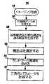
図1は、3次元の基準構造ロケーションと標的構造ロケーションを関連付ける三角形パラメータデータを計算するデータ採取方法に含まれるステップを要約するフローチャートである。図1の方法10を使用して採取される三角形パラメータデータは、3D術中医療画像を使用して画像誘導プロシジャにおいて後で使用されることになる。採取された三角形パラメータデータに基づいて、手術プロシジャ中に取得される3次元医療画像によって規定される3Dボリューム内に、1つの標的部位ロケーションがプロットされることになる。術中画像は、通常、X線透視によって取得されるが、超音波検査等の、利用可能な任意の医療イメージング技術を使用して、取得することもできる。 FIG. 1 is a flow chart summarizing the steps involved in a data collection method for calculating triangular parameter data that associates a three-dimensional reference structure location with a target structure location. Triangular parameter data collected using the
データ採取方法10のステップ15にて、既存の任意のタイプのイメージング方法(その例は、コンピュータ断層撮影法(CT)及び磁気共鳴イメージング(MRI)を含むが、それらに限定されない)を使用して、患者又は志願者からのボリューム医療画像が収集される。或るアプリケーションでは、画像は、三角形測定値から生理的運動アーチファクトを減らすために時間ゲート制御された画像である。画像は、三角形パラメータ測定値に対する呼吸運動及び心臓運動の影響を減らすために、呼吸周期及び/又は心周期の特定の時点にゲート制御されてもよい。 At
一連のボリューム画像が一旦取得されると、画像が積重ねられて、ステップ20にて、空間的に正確な3D画像ボリュームが形成される。ミネソタ州ロチェスターのMayo Clinicで開発され、AnalyzeDirectによって販売されるAnalyzeという医用画像解析ソフトウェアパッケージが、ステップ20を実施するのに使用されてもよい。ステップ20において取得された画像ボリュームは、画像を採取する患者又は志願者の体内で見出される真の解剖学的構造の仮想表現として役立つ。画像ボリュームは、標的構造と選択された基準構造とを含むように採取される。3D術中画像上に1つの標的構造のロケーションをプロットするのに使用することができる三角形パラメータデータのセットを生成するために、少なくとも3つの基準構造が必要とされることが予想される。 Once a series of volume images has been acquired, the images are stacked to form a spatially accurate 3D image volume at
基準構造は、標的構造に比べて、医療画像上で、一般に、より容易に位置決めされ特定される構造として選択されてもよい。互いに対して、また、標的構造に対して、選択される基準構造の解剖学上のロケーションの変動が小さいほど、手術プロシジャ中に標的構造の推定されるロケーションをプロットする時の精度が高くなるであろう。このデータ採取フェーズでは、複数の基準点が最初に選択され、一部の点は、三角形パラメータの望ましくない変動性を引き起こす大きな解剖学的変動のために、後で排除されてもよい。 The reference structure may be selected as a structure that is generally more easily positioned and identified on the medical image than the target structure. The smaller the variation in the anatomical location of the selected reference structure relative to each other and relative to the target structure, the greater the accuracy in plotting the estimated location of the target structure during the surgical procedure. I will. In this data collection phase, multiple reference points are initially selected, and some points may later be eliminated due to large anatomical variations that cause undesirable variability in the triangular parameters.
基準構造は、解剖学的構造に限定されない。埋め込み式デバイスが、基準構造として選択されてもよい。ペースメーカ、薬剤ポンプ、リード線、整形外科挿入物、又は他のデバイス等の、埋め込み可能デバイスが、患者の体内に既に存在してもよい。埋め込み可能デバイスは、画像誘導プロシジャ中に基準構造の役目を果たすために設置されてもよい。たとえば、カテーテル先端又は他のタイプのマーカが、基準構造の役目を果たすために、所望のロケーションに配置されてもよい。 The reference structure is not limited to an anatomical structure. An implantable device may be selected as the reference structure. Implantable devices such as pacemakers, drug pumps, leads, orthopedic inserts, or other devices may already exist in the patient's body. An implantable device may be installed to serve as a reference structure during an image guidance procedure. For example, a catheter tip or other type of marker may be placed at a desired location to serve as a reference structure.
先に述べたように、標的構造は、解剖学的構造、病理学的特徴、又は埋め込み式デバイスであってよい。医療介入は、組織を切除するため、組織を除去するため、薬物又は生物学的物質を送出するため、新しい医療デバイスを埋め込むため、既存の埋め込み式医療デバイスを取り除くか、再配置するか、若しくはその他の方法で変更若しくは調整するため、又は、標的部位において他のプロシジャを実施するために実施されてもよい。 As previously mentioned, the target structure may be an anatomical structure, a pathological feature, or an implantable device. Medical interventions include excising tissue, removing tissue, delivering drugs or biological materials, implanting new medical devices, removing or repositioning existing implantable medical devices, or It may be implemented to change or adjust in other ways, or to perform other procedures at the target site.
ステップ25〜35は、基準構造及び標的構造のそれぞれのロケーションを規定するランドマーク点座標を規定することを対象とする。それぞれの各構造についてランドマーク点を規定するための、多くの方法が利用されてもよい。一実施形態では、ユーザは、指示ツールを使用して、構造に相当する医療画像における1点を単に選択してもよい。その場合、選択された点の座標が、その構造についてのランドマーク点座標として規定されることになる。選択される点は、構造の特定可能な側面であってもよく、手術プロシジャ中における、プロットされる標的構造ロケーションの精度を上げるために、再現性がある方法で選択可能である。ランドマーク点は、別法として、デジタル化されたグレースケール画像又はカラー画像において構造上の1点を特定する自動化技法を使用して選択されてもよい。別の実施形態では、また、図1に示すように、ランドマーク点座標は、3D画像ボリュームを通る、ランドマーク点が決定されている構造を含む斜面を最初に生成することによって決定されてもよい。Analyzeソフトウェアパッケージ内に見出される「斜断面(ObliqueSections)」モジュールが、このステップを実施するのに使用されてもよい。標的構造を通る1つの平面が生成される。選択された基準構造のそれぞれを通る、付加的な平面が生成される。1つの具体的に示すアプリケーションでは、冠状静脈洞口(CSos)のカニューレ挿入を必要とするプロシジャについての三角形パラメータデータ採取は、標的CSosを通る1つの平面を生成すること、及び、たとえば、上大静脈(SVC)口と三尖弁(TV)輪として選択されることができる2つの基準構造を通る2つの平面を生成することを含み得る。Steps 25-35 are directed to defining landmark point coordinates that define the location of each of the reference structure and the target structure. Many methods for defining landmark points for each respective structure may be utilized. In one embodiment, the user may simply select a point in the medical image corresponding to the structure using the pointing tool. In that case, the coordinates of the selected point will be defined as the landmark point coordinates for that structure. The points selected may be identifiable aspects of the structure and can be selected in a reproducible manner to increase the accuracy of the plotted target structure location during the surgical procedure. The landmark points may alternatively be selected using automated techniques that identify a structural point in a digitized grayscale or color image. In another embodiment, and as shown in FIG. 1, the landmark point coordinates may be determined by first generating a slope through the 3D image volume that includes the structure for which the landmark point is determined. Good. "Oblique section" found in the Analyze software package Sections) module may be used to perform this step. A plane through the target structure is generated. Additional planes are created through each of the selected reference structures. In one specific application, triangular parameter data collection for a procedure that requires cannulation of the coronary sinus ostium (CSos) generates a single plane through the target CSos and, for example, the superior vena cava It may include generating two planes through two reference structures that can be selected as (SVC) mouth and tricuspid valve (TV) rings.
斜面は、各平面が、それぞれの標的構造及び基準構造の2D形状を最もよく表すように、3Dボリュームを通って生成される。先に示した例では、SVC口の平面は、SVCの周囲の、SVCが右心房に入るところを含むように生成されるであろう。TV輪の平面は、右心房と右心室の間の境界面にある弁の周囲を含むように生成され、CSosの平面は、右心房の壁に沿ったCSosの周囲を含むように生成されるであろう。 Slopes are generated through the 3D volume so that each plane best represents the 2D shape of the respective target structure and reference structure. In the example shown above, the plane of the SVC mouth will be generated to include the area around the SVC where the SVC enters the right atrium. The plane of the TV wheel is generated to include the perimeter of the valve at the interface between the right atrium and the right ventricle, and the plane of the CSos is generated to include the perimeter of the CSos along the right atrial wall. Will.
標的構造及びそれぞれの基準構造について、平面が一旦生成されると、関連する構造を規定する点が、ステップ30にて選択される。一実施形態では、各構造の境界に沿った点が、指示ツールを使用して手作業で選択されてもよい。他の実施形態では、点の選択は自動化されてもよい。たとえば、点は、デジタル化されたグレースケール画像又はカラー画像の境界検出に基づいて、自動的に選択されてもよい。 For the target structure and each reference structure, once a plane has been generated, a point defining the associated structure is selected at
Analyzeソフトウェアの「斜断面」モジュール内の点ピッキングツールが、ステップ30を実施するのに使用されてもよく、選択された境界点又は縁座標の各セットは、テキストファイルにセーブすることができる。 A point picking tool in the “slanted section” module of the Analyze software may be used to perform
ステップ35にて、各基準構造及び標的構造について、ランドマーク点座標が求められる。図1に示す実施形態では、所与の構造についてのランドマーク点座標は、ステップ30において選択された点のうちの1つ又は複数から求められる。ランドマーク点座標は、イメージングボリューム内の関連する構造のロケーションを規定する。一実施形態では、ランドマーク点は、構造の縁又は周囲に沿って選択される点から計算される重心であってよい。ランドマーク座標は、Matlabソフトウェア(マサチューセッツ州ナティックのMathworks)等の市販のソフトウェアを使用して計算されてもよい。「centroid.m」と呼ぶ、本発明者が開発した簡単なMatlabスクリプトは、選択された境界点座標のスケーリングされたセットを取得し、これらの点の平均的なロケーション(重心としても知られる)を計算する。標的構造ランドマーク点及び選択された基準構造ランドマーク点に相当する、ステップ35において求めたランドマーク点座標セットについて、三角形パラメータが、ステップ37にて求められる。基準構造ランドマーク点間の距離及び基準構造ランドマーク点と標的構造ランドマーク点の間の距離が求められる。2つの基準構造間の距離に対して、基準構造と標的構造の間の距離を関連付ける距離比が、次に、求められる。距離測定値の比を利用することによって、構造の空間的な関係を、測定単位又は体のサイズに関わらず推定することができる。 At
ステップ37にて、ランドマーク点間に延びる線分間の角度もまた求められる。計算された距離比及び角度を使用して、標的構造のロケーションが、推定され、基準構造のロケーションがわかっている画像内にプロットされることができる。 At
本発明者が開発した、重心を計算するのに使用する同じMatlabスクリプトを使用して、ランドマーク点のそれぞれの間の距離を計算することができる。これらの距離は、標的構造及び2つの基準構造のランドマーク点によって規定される三角形の各斜辺の長さを規定する。計算された距離の比、及びランドマーク点の三角形によって形成された3つのベクトル対のそれぞれの間の角度を求めることができる。一実施形態では、ステップ37において求められる三角形パラメータは、2つの基準ランドマーク点及び標的ランドマーク点をそれぞれ含む2つの異なる三角形から求めた、少なくとも2つの距離比及び2つの角度を含む。 The same Matlab script developed by the inventor and used to calculate the center of gravity can be used to calculate the distance between each of the landmark points. These distances define the length of each hypotenuse of the triangle defined by the landmark points of the target structure and the two reference structures. The calculated distance ratio and the angle between each of the three vector pairs formed by the triangles of landmark points can be determined. In one embodiment, the triangle parameters determined in
方法10は、患者固有の方法で実施することができ、方法10は、プロシジャを受ける患者に関して予想して実施される。その患者について以前に求めた三角形パラメータがプロシジャ中に適用されて、基準構造ロケーションが特定されている、採取された術中画像上に標的構造の推定されるロケーションがプロットされる。
方法10は、基準構造及び標的構造のセットについての代表的な三角形パラメータを求めることができるように、母集団から選択された多数の被検体で実施することができる。画像誘導プロシジャを受けている所与の患者において、標的構造の定位に役立つために、患者の母集団において変動性が低い三角形パラメータを使用することができる。多数の被検体で求めた三角形パラメータは、三角形パラメータの代表的なセットを求めるために、統計的に解析されてもよい。たとえば、三角形パラメータの平均値が求められてもよい。患者の母集団から取得される三角形パラメータデータは、予想的なデータ収集イメージングプロシジャが患者固有の方法で実施されることが時間的に許されない緊急プロシジャ時に使用するために、即座に利用可能であることができる。
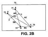
図2Aと図2Bは、データ採取方法10(図1)中に計算することができる三角形パラメータのセットを示す。これらのパラメータは、3D術中画像を利用する画像誘導手術プロシジャ中の定位方法において使用されることになる。1つの標的構造ロケーションが3D術中画像内にプロットされることを可能にする三角形パラメータを求めるのに、少なくとも3つの基準点が一般に必要とされることになることが予想される。図2Aでは、3つの基準ランドマーク点71、72、及び73並びに標的構造ランドマーク点75が特定されている。2つの基準ランドマーク点71及び72並びに標的ランドマーク点75によって、三角形ABCが形成される。三角形ABCから求められる三角形パラメータのセットは、1つの距離比と1つの角度とを含むことになる。距離比は、基準ランドマーク点71又は72のいずれかと標的ランドマーク点75の間の距離と、2つの基準ランドマーク点71と72の間の距離の比であることになる。たとえば、距離ACとABは、ランドマーク点座標から距離比AC:ABを計算することによって求められてもよい。三角形の辺AC及びABによって囲まれる角度(角度1)もまた、ランドマーク点座標から計算される。 2A and 2B show a set of triangular parameters that can be calculated during the data acquisition method 10 (FIG. 1). These parameters will be used in a localization method in an image guided surgical procedure that utilizes 3D intraoperative images. It is expected that at least three reference points will generally be needed to determine the triangle parameters that allow one target structure location to be plotted in the 3D intraoperative image. In FIG. 2A, three reference landmark points 71, 72, and 73 and a target
図2Bでは、第3の基準ランドマーク点73、ランドマーク点72、及び標的ランドマーク点75によって形成される三角形DBCから、三角形パラメータの第2のセットが求められる。三角形パラメータの第2のセットもまた、三角形DBCから求めた距離比と角度とを含む。たとえば、距離比DC:DBと角度2が、ランドマーク点座標から計算されてもよい。 In FIG. 2B, a second set of triangle parameters is determined from the triangle DBC formed by the third
プロットされる1つの標的点ロケーションの精度を高めるために、さらなる基準構造が選択されてもよい。或る3次元アプリケーションでは、三角形パラメータは、4つ以上の基準構造が選択される時に形成される3つ以上の三角形について収集されてもよい。3つの基準構造について、3つのランドマーク点が特定される場合、3つの基準ランドマーク点及び標的ランドマーク点によって形成される2つの三角形について、1つの距離比と1つの角度とをそれぞれ含む三角形パラメータの2つのセットが求められる。他の実施形態では、4つ以上の基準構造ランドマーク点及び標的構造ランドマーク点を使用して形成される三角形から、さらなる三角形パラメータが求められてもよい。三角形データのセットを取得するのに使用される基準構造の数を増やすことによって、1つの標的部位ロケーションを予測する時の誤差を最小にすることができる。術中画像内でさらなる基準構造を特定するために、侵襲プロシジャ中により多くの時間が必要とされる場合があるが、標的部位ロケーションは、より正確に予測されることができ、全体のプロシジャ時間が減る。 Additional reference structures may be selected to increase the accuracy of one target point location plotted. In certain 3D applications, triangle parameters may be collected for more than two triangles that are formed when more than four reference structures are selected. For three reference structures, when three landmark points are specified, a triangle that includes one distance ratio and one angle for two triangles formed by the three reference landmark points and the target landmark point, respectively. Two sets of parameters are determined. In other embodiments, additional triangle parameters may be determined from triangles formed using four or more reference structure landmark points and target structure landmark points. By increasing the number of reference structures used to acquire the triangle data set, errors in predicting one target site location can be minimized. Although more time may be required during the invasive procedure to identify additional reference structures in the intraoperative image, the target site location can be predicted more accurately and the overall procedure time decrease.
3Dイメージングプロシジャ中に、基準構造又は標的構造を位置決めする他の技法に頼ってもよい。たとえば、心臓内の電気生理学的構造を位置決めするのを補助するために、電気生理学的測定を実施してもよい。本発明の別の例のアプリケーションでは、本明細書に述べる定位方法は、臨床医がヒス束にペーシング電極を設置するのを誘導するのに使用されてもよい。3Dイメージング及び電気生理学的マッピングに頼るデータ収集プロシジャが、ヒス束のロケーションを選択された基準構造に関連付けるのに必要とされる三角形パラメータを取得する時に使用されてもよい。電気生理学的測定は、ヒス束のロケーションを確認するのに使用されるであろう。 Other techniques for positioning the reference structure or target structure during the 3D imaging procedure may be relied upon. For example, electrophysiological measurements may be performed to assist in positioning electrophysiological structures within the heart. In another example application of the present invention, the localization method described herein may be used to guide a clinician to place a pacing electrode on a His bundle. A data acquisition procedure that relies on 3D imaging and electrophysiological mapping may be used in obtaining the triangular parameters needed to associate the His bundle location with the selected reference structure. Electrophysiological measurements will be used to confirm the location of the His bundle.
図3Aは、推定された標的構造ロケーションを3D術中画像内にプロットする時に、3次元三角形パラメータを適用する方法に含まれるステップの図である。一部のアプリケーションでは、標的構造と同一平面上にある3つの基準点を使用して、1つの標的構造を定位することができる。図3Aに示す定位方法は、3つの共面基準点から導出された三角形パラメータに基づいて、推定された標的構造ロケーションを3D画像内にプロットする1つの方法を示す。 FIG. 3A is a diagram of the steps involved in applying a 3D triangle parameter when plotting estimated target structure locations in a 3D intraoperative image. In some applications, one target structure can be localized using three reference points that are coplanar with the target structure. The localization method shown in FIG. 3A illustrates one method of plotting estimated target structure locations in a 3D image based on triangular parameters derived from three coplanar reference points.
ステップ102にて、術中画像フレーム101内で、3つの基準構造71、72、及び73のロケーションが、ユーザによってマークされる。画像フレーム101は、基準構造と標的構造のそれぞれを含むものと予想されるボリュームの3D画像である。ユーザは、指示ツール、タッチスクリーン、又はイメージングシステムに適合する他のユーザ機器を使用して、基準構造のロケーションを指定することができる。ユーザは、プロットされる標的構造ロケーションの精度を高めるために、各基準構造のロケーションを、三角形データを取得する時に使用する各ランドマーク点に相当する点にマークするように試みるべきである。たとえば、ランドマーク点座標が、構造の重心に相当する場合、臨床医は、画像101内で重心をマークするように試みるべきである。 In
基準構造ロケーション71、72、及び73をマークした後、ステップ104にて、術中画像101内の基準構造71と72の間の距離が測定される。図2A及び図2Bに示すラベル付けの取り決めを使用すると、測定された距離は、2つの基準構造71及び72並びに標的構造によって形成された三角形ABCの1つの斜辺の距離ABに相当する。標的構造のロケーションを推定するために、単位無しの距離比が適用されることになるため、距離ABは、任意の単位で測定することができる。 After marking
3D三角形パラメータのアプリケーションの背後にある数学を可視化する、いくつかの可能な方法のうちの1つの方法は、特定された基準点ロケーション及び三角形パラメータによって規定される空間で円を考えることである。ステップ106にて、三角形パラメータを適用して、円110を生成する。角度1で線分ABの周りに軌道が回転して、その周囲が点71から距離ACのところに位置する円110が規定される。距離ACは、以前に求めた距離比AC:ABと、画像101において測定した距離ABとから求められる。角度1は、図2Aで述べたように以前に求めた角度である。 One of several possible ways to visualize the mathematics behind the application of 3D triangle parameters is to consider a circle in the space defined by the identified reference point location and triangle parameters. In
標的ランドマーク点は、円110上に、又は、ほぼ円110上に位置する。データ採取方法10中に取得される三角形パラメータデータの第2のセットは、標的ランドマーク点が円110上のどこに位置するかを推定するのに使用される。ステップ108にて、線分DBから角度2で基準点73から延びる軌道を回転させることによって、第2の円114が生成される。円114の円周は、以前に求めた距離比DC:DBと、画像101において測定された距離DBとから求められるように、点73から距離DCのところに位置する。 The target landmark point is located on or approximately on the
標的ランドマーク点76は、円110と114が交差する点にプロットされる。プロットされた点76は、術中画像上に表示され、臨床医が侵襲プロシジャ中に器具を誘導するための標的を提供する。円110及び114は、表示されてもよく、表示されなくてもよい。図3Aに示す円は、推定される標的構造点76を特定するために使用することができる計算を図示するために示される。 The
プロットされる点76を囲むエリア又は周囲は、三角形パラメータの固有誤差又は変動性を示すために、画像ディスプレイ上で陰影をつけるか、又は、輪郭が表示されてもよい。円110及び114は、その交差点76において、推定される3D標的ボリュームを生じるラインの太さで規定されてもよい。誤差は、画像フレーム101においてユーザが指示した基準構造のロケーション71、72、及び73が、三角形パラメータを求める時に使用されるランドマーク点座標に正確に一致しない時に生じる場合がある。三角形パラメータが、患者母集団から求められる時、個人間の一定の変動性が、測定される距離比及び角度に存在することになり、予想される標的構造ロケーションに変動性が生じる。 The area or perimeter surrounding the
3つの基準点及び標的構造が同一平面上にないアプリケーションでは、三角形パラメータの2つのセットを使用して生成される円110及び114が、2つ以上の点で交差する場合がある。時には、臨床医は、標的構造に相当する、解剖学的に現実的なロケーションに位置していないとして、論理的に1つの交差点を排除することができる場合がある。3つの点が標的構造を定位するのに十分でない場合、標的構造ロケーションを規定する一意の交差点を決定するためのさらに別の円を生成するのに、第4の基準構造が必要とされる場合がある。推定される標的構造ロケーションは、4つの基準ランドマーク点を使用して求めた三角形パラメータの3つのセットを使用して生成された3つの円の交差部にプロットされるであろう。 In applications where the three reference points and the target structure are not coplanar, the
図3Bは、推定される標的構造ロケーションを3D術中画像内にプロットするための、4つの基準ランドマーク点の使用を示す。ステップ130にて、術中画像フレーム101内で、4つの基準構造71、72、73、及び74のロケーションが、ユーザによってマークされる。画像フレーム101は、基準構造と標的構造のそれぞれを含むものと予想されるボリュームの3D画像である。 FIG. 3B shows the use of four reference landmark points to plot the estimated target structure location in a 3D intraoperative image. At
ステップ132にて、三角形パラメータを適用して、円110を生成する。角度1で線分ABの周りに軌道が回転して、その周囲が点71から距離ACのところに位置する円110が規定される。距離ACは、以前に求めた距離比AC:ABと、画像101において測定した距離ABとから求められる。角度1は、図2Aで述べたように以前に求めた角度である。 At
標的ランドマーク点は、円110上に、又は、ほぼ円110上に位置する。データ採取方法10中に取得される三角形パラメータデータの第2のセットは、標的ランドマーク点が円110上のどこに位置するかを推定するのに使用される。ステップ134にて、線分DBから角度2で基準点73から延びる軌道を回転させることによって、第2の円114が生成される。円114の円周は、以前に求めた距離比DC:DBと、画像101において測定された距離DBとから決定されるように、点73から距離DCのところに位置する。 The target landmark point is located on or approximately on the
この例では、2つの基準円110及び114は、2つの点76と77で交差し、そのうちの一方が標的構造である。標的の適切なロケーションを、2つの交差点から引き出すことができない場合、第4の基準点が必要とされる。ステップ136は、第4の基準点74に基づく、三角形パラメータの第3のセットの使用を示す。 In this example, the two
三角形パラメータの第3のセットは、第3の三角形FCBに対応する距離比FC:FBと、角度3とを含むことになる。三角形パラメータの第3のセットは、第3の基準円116を生成するのに使用される。三角形FCBの辺FB(基準点74と72の間に延びる)に対して角度3で第4の基準点74から延びる軌道を回転することによって、円116が生成される。円116の円周は、画像101における測定された距離FBと、以前に求めた距離比FC:FBとから決定されるように、基準点74から距離FCのところに位置する。3つの基準円110、114、及び116の間に、1つの共通交差点76が存在することになり、標的構造ロケーションを規定する。プロットされた点76は、術中画像上に表示され、臨床医が侵襲プロシジャ中に器具を誘導するための標的を提供する。 The third set of triangle parameters will include a distance ratio FC: FB corresponding to the third triangle FCB and an angle of 3. A third set of triangle parameters is used to generate a
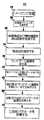
図4は、2次元画像誘導手術プロシジャにおいて使用するための、三角形パラメータ測定値を採取するための方法に含まれるステップを要約するフローチャートである。介入中に、術中画像は、2次元又は3次元で取得されてもよい。3D術中イメージングが利用可能である場合、図1の方法10を使用して取得された三角形パラメータは、先の図3に関連して述べたように、術中3D画像において直接適用されてもよい。しかしながら、術中イメージングが、2DのX線透視等の2D画像に限定される場合、データ採取方法中に取得される3次元ランドマーク座標は、三角形パラメータを計算するために、選択された平面ビュー上に投影される必要がある。 FIG. 4 is a flow chart summarizing the steps involved in a method for taking triangle parameter measurements for use in a two-dimensional image guided surgical procedure. During the intervention, intraoperative images may be acquired in two or three dimensions. If 3D intraoperative imaging is available, the triangle parameters obtained using the
図4に示す方法10’は、標的構造と基準構造のそれぞれについてランドマーク点座標を求めるために、図1に関連して先に述べたように、ステップ15〜35を含む。2D画像誘導アプリケーションでは、2つの基準構造が、一般に、推定される標的構造ロケーションをプロットする時に使用するのに十分であることが予想される。ステップ60にて三角形パラメータを計算する前に、ランドマーク点は、予定されるプロシジャ中に使用されることになる2次元平面ビュー上に投影される必要がある。 The method 10 'shown in FIG. 4 includes steps 15-35 as described above in connection with FIG. 1 to determine landmark point coordinates for each of the target structure and the reference structure. In 2D image guidance applications, two reference structures are generally expected to be sufficient for use when plotting estimated target structure locations. Prior to calculating the triangle parameters at
方法10’のステップ40にて、1つのロケーションが3D画像ボリューム内で計算され、このロケーションは、2次元画像が周りを回転する、患者の体又は体領域のアイソセンタ軸に等しい。たとえば、2DのX線透視によって誘導される一般的な侵襲プロシジャにおいて、X線透視Cアームが周りを回転することになる、胸郭空洞のアイソセンタ軸が決定されてもよい。体領域のアイソセンタは、指定されたロケーションにおいて、イメージングボリューム内の領域の高さ及び幅を測定することによって決定されてもよい。各寸法の中央点を通過する軸が、アイソセンタ軸として決定される。2Dイメージング平面が周りを回転するアイソセンタ軸を規定するのに使用されるアイソセンタ点のロケーションを求めるために、他の方法が使用されてもよい。 At
1つの例では、胸郭空洞のアイソセンタは、およそ大動脈弁の高さにおいて、各イメージングボリュームの胸郭空洞の幅と高さを測定することによって規定することができる。胸郭空洞の各寸法の中央点がその後決定される。各寸法の中央の交差部において体を通って規定される垂直軸が、ランドマーク点のそれぞれのセットが周りを回転することができる回転軸として使用される。 In one example, the isocenter of the thoracic cavity can be defined by measuring the width and height of the thoracic cavity of each imaging volume at approximately the height of the aortic valve. The center point of each dimension of the rib cage cavity is then determined. The vertical axis defined through the body at the center intersection of each dimension is used as the axis of rotation around which each set of landmark points can rotate.
図5は、患者の胸郭空洞のアイソセンタ80と、2DのX線透視ビューを取得するために、標準的なCアームが周りを回転することができるアイソセンタ軸82とを示す。X線透視ビューに利用されるいくつかの回転角、すなわち、30°右前傾斜角84、30°左前傾斜角86、及び60°左前傾斜角88が示される。 FIG. 5 shows an
図4のフローチャートのステップ45にて、ランドマーク点を選択された平面ビュー上に投影するために、基準構造と標的構造のランドマーク点座標が、アイソセンタ軸の周りに回転する。選択された平面ビューは、画像誘導のための手術プロシジャ中に使用されることを意図された平面ビューに相当する。本発明者が開発し、「CSlocrotation.m」と呼ぶ別のMatlabコードを、ステップ45にて使用して、3つのランドマーク点座標のそれぞれと、アイソセンタ規定点とを統合することができ、ユーザが、アイソセンタ軸の周りで、ランドマーク点をいずれかの方向にいろいろな角度で回転させることを可能にする。 In
これらの点が、アイソセンタ軸の周りで所与の角度に回転した後、ステップ50にて、平行投影方法を使用して、選択された平面上に点が投影される。結果として得られる2Dランドマーク点座標は、その後、所与の角度回転において2次元画像上でどのように現れるかを表すためにプロットされる。ステップ60にて計算される三角形パラメータは、選択された2D平面ビュー内の投影されたランドマーク点座標によって形成される三角形から求められる距離比と角度である。 After these points have rotated to a given angle around the isocenter axis, at step 50 the points are projected onto the selected plane using a parallel projection method. The resulting 2D landmark point coordinates are then plotted to represent how they appear on the two-dimensional image at a given angular rotation. The triangle parameter calculated in
図6は、2Dシステムにおいて投影されたランドマーク点座標から計算することができる三角形パラメータを示す。CSosを定位するための、先の例で述べたランドマーク点が、胸郭空洞のアイソセンタの周りを、30°の左前傾斜(LAO)角度に回転した場合、投影された点は、図6に示す三角形に似たものに見える。図6では、選択された画像平面95における、それぞれA及びBとラベル付けされた、2つの投影された基準ランドマーク点90及び92、並びに、Cとラベル付けされた、投影された標的構造ランドマーク点94によって三角形ABCが形成される。CSosを定位する例では、基準ランドマーク点90は上大静脈ランドマーク点に相当し、基準ランドマーク点92は三尖弁ランドマーク点92に相当し、標的ランドマーク点94はCSosに相当し得る。 FIG. 6 shows triangle parameters that can be calculated from the landmark point coordinates projected in the 2D system. When the landmark points mentioned in the previous example for localization of CSos are rotated around the isocenter of the thorax cavity to a 30 ° left forward tilt (LAO) angle, the projected points are shown in FIG. Looks like a triangle. In FIG. 6, two projected reference landmark points 90 and 92 labeled A and B, respectively, and a projected target structure land labeled C in the selected
投影されたランドマーク点90、92、及び94によって形成される三角形ABCのそれぞれの各斜辺の距離AB、BC、及びACは、投影されたランドマーク座標値から計算することができる。これらの距離は、三角形ABCの辺の長さを関連付ける距離比を計算するのに使用される。 The distances AB, BC, and AC of each hypotenuse of the triangle ABC formed by the projected landmark points 90, 92, and 94 can be calculated from the projected landmark coordinate values. These distances are used to calculate a distance ratio that relates the length of the sides of the triangle ABC.
通常、1)第1の基準ランドマーク点から第2の基準ランドマーク点までの距離及び2)第1の基準ランドマーク点から標的ランドマーク点までの距離を含む2つの距離が計算されることになる。示す例では、基準ランドマーク点90と基準ランドマーク点92の間の距離である距離ABが、基準ランドマーク点90と標的ランドマーク点94の間の距離である距離ACと共に計算することができる。その後、距離ABと距離ACの比が計算されてもよい。他の例では、距離ABと距離BCが計算されて、距離比を求めてもよい。距離比は、一般に、2つの基準ランドマーク点90と92の間の距離を、基準ランドマーク点90又は92の一方と標的ランドマーク点94の間の距離に関連付ける。 Typically, two distances are calculated, including 1) the distance from the first reference landmark point to the second reference landmark point and 2) the distance from the first reference landmark point to the target landmark point. become. In the example shown, the distance AB, which is the distance between the
距離比に加えて、少なくとも1つの角度が測定される。距離比が、距離ABと距離ACを用いて計算される場合、ベクトルABとベクトルACの間で形成される角度1が、各ランドマーク点座標から計算される。距離比が、距離CAと距離CBを用いて計算される場合、これらのベクトルによって形成される角度3が計算される。距離比及び関連する角度測定値を知ることによって、基準構造を含む術中画像において、標的構造のロケーションを予想することができる。 In addition to the distance ratio, at least one angle is measured. When the distance ratio is calculated using the distance AB and the distance AC, the angle 1 formed between the vector AB and the vector AC is calculated from each landmark point coordinate. If the distance ratio is calculated using distance CA and distance CB, the angle 3 formed by these vectors is calculated. By knowing the distance ratio and associated angular measurements, the location of the target structure can be predicted in intraoperative images that include the reference structure.
図7は、標的構造を2次元術中画像上にプロットするために、画像誘導プロシジャ中に三角形パラメータを適用する方法に含まれるステップを示すフロー図である。ステップ122にて、術中画像フレーム121内で、基準構造90及び基準構造92のロケーションが、ユーザによってマークされる。画像フレーム121は、選択されたビュー平面の2D画像である。ユーザは、指示ツール、タッチスクリーン、又はイメージングシステムに適合する他のユーザ機器を使用して、基準構造90及び基準構造92のロケーションを指定することができる。ユーザは、プロットされる標的構造ロケーションの精度を高めるために、各基準構造のロケーションを、三角形データを取得する時に使用する各ランドマーク点に相当する点にマークするように試みるべきである。 FIG. 7 is a flow diagram illustrating the steps involved in applying a triangular parameter during an image guidance procedure to plot a target structure on a two-dimensional intraoperative image. At
基準構造ロケーションをマークした後、ステップ124にて、術中画像121内の基準構造90と基準構造92との間の距離が測定される。測定された距離は、図6に示すように、2つの基準構造と標的構造によって形成された三角形の1つの斜辺の距離ABに相当する。標的構造のロケーションを推定するために、単位無しの距離比が適用されることになるため、距離ABは、任意の単位で測定することができる。 After marking the reference structure location, the distance between the
ステップ126にて、標的構造の推定されるロケーション96をプロットするために、三角形パラメータが適用される。一実施形態では、図6に示すラベル付けの取り決めを使用して、画像フレーム121における測定された距離ABは、距離比AC:ABを乗算されて、基準構造90と標的構造の間の距離ACが求められる。その後、点96は、辺ABから角度1で延びるベクトルに沿って、基準構造90から距離ACのところにプロットされる。プロットされた点96は、臨床医が侵襲プロシジャ中に器具を誘導するための標的を提供する。プロットされた点96を囲むエリア又は周囲は、三角形パラメータの固有誤差又は変動を示すために、陰影をつけるか、又は、輪郭が表示されてもよい。 At
CSosを定位するための先に述べた例は、臨床状況において、平均の三角形パラメータを適用する方法をさらに述べるために使用されてもよい。標的のCSos並びにSVC及びTVの基準構造のロケーションを関連付ける三角形パラメータを、選択された患者母集団からの多数の被検体から得ることができる。所与の患者母集団から、(図5に示すように)LAO30°観察方向において、三角形の、SVC−TV斜辺とSVC−CSos斜辺の間の距離比及びSVC−TV斜辺とSVC−CSos斜辺の間の角度の変動が小さいという仮定が行われてもよい。 The above-described example for localizing CSos may be used to further describe how to apply average triangle parameters in a clinical situation. Triangular parameters relating the location of the target CSos and SVC and TV reference structures can be obtained from multiple subjects from the selected patient population. From a given patient population, in the
CSosのカニューレ挿入を必要とするプロシジャ中に、医師は、患者の心臓をLAO30回転角度から観察するために、X線透視Cアームの向きを制御し、その後、カテーテルを使用して、医師は、SVC口及びTV輪の中心点を位置決めし、X線透視ビュー上でこれらのロケーションをマークする。これらの点は、X線透視画像を表示するモニタ上で手作業でマークされてもよく、又は、ソフトウェアパッケージによって、画像上に電子的にマークされてもよく、同様に、X線透視ビュー上のこれらの点間の距離は、定規と2点間に引いたラインとを使用して測定されるか、又は、ソフトウェアパッケージによって計算されることができる。その後、選択された患者母集団に関する、以前に生成された三角形パラメータデータベースを使用して、三角形のSVC−CSos斜辺の長さは、三角形のSVC−TV斜辺とSVC−CSos斜辺の間の距離比測定値を使用して計算されることになる。その後、三角形のSVC−CSos斜辺の軌道は、X線透視ビュー上の既存のライン(SVC−TV斜辺)と、三角形パラメータデータベースから既に規定された角度測定値とを使用することによって、規定されることになる。 During a procedure requiring CSos cannulation, the physician controls the orientation of the fluoroscopic C-arm to observe the patient's heart from the
X線透視スクリーン上に、長さと軌道計算結果から得られる、CSosの予想されるロケーションに相当する点をプロットした後、母集団において見出される変動に基づく周囲が、予想されるCSosロケーションの周りに描かれ、医師が、冠状静脈洞にカニューレ挿入するのを誘導するための標的を提供する。患者固有の定位方法が使用される場合、医師は、母集団ベースのツールについて先に概説したステップと同じステップに従うことができ、唯一の違いは、患者母集団の変動がなくなるため、標的が小さいことである。 After plotting points on the fluoroscopy screen that correspond to the expected location of the CSos obtained from the length and trajectory calculation results, the perimeter based on the variation found in the population is around the expected CSos location. Depicted and provides a target to guide the physician to cannulate the coronary sinus. If patient-specific localization methods are used, the physician can follow the same steps outlined above for the population-based tool, the only difference being the small target because there is no patient population variation That is.
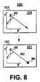
図8は、1つの基準構造と局所座標系から求められる定位パラメータが、術中画像内での標的構造ロケーションをプロットする時に使用される、本発明のさらに別の実施形態に含まれるステップを要約する図である。一部のアプリケーションでは、単一の基準構造90が選択されてもよい。手術プロシジャの前に実施されるデータ採取方法では、基準構造ランドマーク点と標的ランドマーク点の間の距離が測定される。局所座標軸と、標的ランドマーク点の方向に基準ランドマーク点から延びる軌道との間の角度が求められる。局所座標軸は、イメージングエリア121に対して規定される。この距離測定値と角度は、画像誘導プロシジャ中に推定された標的構造ロケーションをプロットする方法において使用される。 FIG. 8 summarizes the steps involved in yet another embodiment of the present invention where the localization parameters determined from one reference structure and local coordinate system are used when plotting the target structure location in the intraoperative image. FIG. In some applications, a
図8に示すように、2次元術中画像101内の基準構造90のロケーションは、ステップ105にて、臨床医によってマークされる。局所座標系の軸、この例では、Y軸から角度1’で基準点90から延びる軌道が生成される。ステップ107にて、標的点96は、軌道に沿って、基準点90から距離ACのところにプロットされる。距離ACは、基準点90と標的ランドマーク点の間の、データ採取中に測定された距離に相当する。そのため、一部のアプリケーションでは、標的点ロケーションは、最低1つの基準構造と、規定された局所座標系を使用してプロットされてもよい。定位パラメータデータは、距離比ではなく絶対距離測定値を含む。 As shown in FIG. 8, the location of the
本明細書に述べる方法は、一連の構造を位置決めするために、段階的な方法で適用されてもよい。たとえば、カテーテル又はリード線を心臓静脈内に設置するプロシジャにおいて、本明細書に述べる方法は、最初に、冠状静脈洞口を定位するために適用されてもよい。冠状静脈洞口が一旦位置決めされると、冠状静脈洞口は、標的心臓静脈を位置決めするための、基準構造として使用されてもよい。標的心臓静脈を定位するために、CSosのロケーション及び第2の基準構造、たとえば、三尖弁を関連付ける三角形パラメータが取得されてもよい。こうして、最初の定位ステップにおける標的構造は、最終の治療送出部位又は診断部位に器具を最終的に誘導するために実施される第2の定位ステップにおける基準構造として使用されてもよい。 The methods described herein may be applied in a step-wise manner to position a series of structures. For example, in procedures that place a catheter or lead in a cardiac vein, the methods described herein may be first applied to localize the coronary sinus ostium. Once the coronary sinus ostium is positioned, the coronary sinus ostium may be used as a reference structure for positioning the target cardiac vein. In order to localize the target cardiac vein, a triangle parameter relating the location of the CSos and a second reference structure, eg, a tricuspid valve, may be obtained. Thus, the target structure in the first localization step may be used as a reference structure in the second localization step performed to ultimately guide the instrument to the final therapy delivery site or diagnostic site.
こうして、以前に求めた三角形パラメータに基づいて術中画像上に標的構造ロケーションをプロットする方法が述べられた。本発明によって提供される方法は、2D又は3Dイメージングシステムを使用した精密な構造定位を必要とするあらゆる介入において使用することができる。本発明が有益である場合があるプロシジャは、CSosカニューレ挿入、ペーシングリード線の設置、薬剤、生物学的物質、又は遺伝子物質の局所送出、組織切除、経皮的弁設置、及び生理的センサの設置を含むが、それらに限定されない。臨床医が標的構造を定位するのを補助するために、本発明を使用することで、プロシジャ時間を減らし、少数のX線透視画像しか必要としないことによって、放射線被曝を減少させることができ、より予測可能な治療結果がもたらされる。定位方法の使用は、特定のプロシジャを実施する時の医師の自信を増加させ、プロシジャを学習するのに必要とする医師の訓練時間を減らす。本明細書に述べる方法は、本発明を実施するための例示的な方法を示すことを意図され、添付の特許請求の範囲に関して制限することを意図しない。 Thus, a method for plotting target structure locations on intraoperative images based on previously determined triangle parameters has been described. The method provided by the present invention can be used in any intervention that requires precise structural orientation using 2D or 3D imaging systems. Procedures in which the present invention may be useful include CSos cannulation, pacing lead placement, local delivery of drugs, biological or genetic material, tissue ablation, percutaneous valve placement, and physiological sensor Including but not limited to installation. Using the present invention to help the clinician localize the target structure, radiation exposure can be reduced by reducing procedure time and requiring only a few fluoroscopic images, More predictable treatment results are provided. The use of the stereotactic method increases the physician's confidence when performing a particular procedure and reduces the physician's training time required to learn the procedure. The methods described herein are intended to illustrate exemplary methods for practicing the invention and are not intended to be limiting with respect to the appended claims.
Claims (32)
Translated fromJapanese該生成した3次元画像内に位置する複数の基準構造を選択すること、
前記標的構造及び前記基準構造のそれぞれのロケーションを規定するためにランドマーク点座標を計算することであって、それによって、それぞれの標的構造ランドマーク点座標と基準構造ランドマーク点座標を生成する、ランドマーク点座標を計算すること、
前記基準構造ランドマーク点座標に対して、前記標的構造ランドマーク点座標の前記ロケーションを関連付ける三角形パラメータを計算すること、
前記手術プロシジャ中に、術中3次元画像を採取すること、
該術中画像内で前記基準構造のロケーションを特定すること、並びに
前記計算された三角形パラメータと、前記術中画像内での前記基準構造の前記特定されたロケーションとに応じて、前記術中画像上に前記標的構造のロケーションをプロットすること、
を含む方法。Generating a three-dimensional image of a body part including one target structure for a surgical procedure;
Selecting a plurality of reference structures located in the generated three-dimensional image;
Calculating landmark point coordinates to define respective locations of the target structure and the reference structure, thereby generating respective target structure landmark point coordinates and reference structure landmark point coordinates; Calculating landmark point coordinates,
Calculating a triangle parameter that relates the location of the target structure landmark point coordinate to the reference structure landmark point coordinate;
Taking an intraoperative 3D image during the surgical procedure;
Determining the location of the reference structure in the intraoperative image, and on the intraoperative image in response to the calculated triangular parameter and the specified location of the reference structure in the intraoperative image. Plotting the location of the target structure;
Including methods.
前記標的構造及び前記選択された基準構造のそれぞれを通る別個の斜面を生成すること、
該各斜面のそれぞれにおいて、前記標的構造及び前記基準構造の1つに相当する複数の点を選択すること、及び
該選択された複数の点に応じて前記ランドマーク点座標を計算することを含む、請求項1に記載の方法。Calculating the landmark point coordinates
Generating a separate ramp through each of the target structure and the selected reference structure;
Selecting a plurality of points corresponding to one of the target structure and the reference structure on each of the slopes, and calculating the landmark point coordinates according to the selected points. The method of claim 1.
第1の特定された基準構造及び第2の特定された基準構造によって規定される線分に対して、対応する計算された角度で前記第1の特定された基準構造から延びる軌道を回転させることによって規定される第1の円を生成することであって、該円の円周は、前記第1の特定された基準構造から或る距離だけ離れており、該距離は、対応する計算された距離比と、前記第1の特定された基準構造及び前記第2の特定された基準構造の間の、前記術中画像内で測定された距離とから求められる、第1の円を生成すること、
第3の特定された基準構造及び前記第2の特定された基準構造によって規定される線分に対して、対応する計算された角度で前記第3の特定された基準構造から延びる軌道を回転させることによって第2の円を生成することであって、該円の円周は、前記第3の特定された基準構造から或る距離だけ離れており、該距離は、前記対応する計算された距離比と、前記第3の特定された基準構造及び前記第2の特定された基準構造の間の、前記術中画像内で測定された距離とから求められる、第2の円を生成すること、並びに
前記第1の円と前記第2の円の交差部に、前記標的構造の前記ロケーションをプロットすることを含む、請求項8に記載の方法。Plotting the location of the target structure in the intraoperative image is
Rotating a trajectory extending from the first identified reference structure at a corresponding calculated angle relative to a line segment defined by the first identified reference structure and the second identified reference structure; Generating a first circle defined by the circle, the circumference of the circle being a distance away from the first identified reference structure, the distance calculated correspondingly Generating a first circle determined from a distance ratio and a distance measured in the intraoperative image between the first identified reference structure and the second identified reference structure;
Rotating a trajectory extending from the third identified reference structure at a corresponding calculated angle relative to a line segment defined by the third identified reference structure and the second identified reference structure Generating a second circle, wherein the circumference of the circle is a distance away from the third identified reference structure, the distance being the corresponding calculated distance Generating a second circle determined from a ratio and a distance measured in the intraoperative image between the third identified reference structure and the second identified reference structure; and 9. The method of claim 8, comprising plotting the location of the target structure at the intersection of the first circle and the second circle.
該画像内に含まれる複数の基準構造を選択すること、
前記標的構造及び前記基準構造のそれぞれのロケーションを規定するためにランドマーク点座標を計算することであって、それによって、それぞれの標的構造ランドマーク点座標及び基準構造ランドマーク点座標を生成する、ランドマーク点座標を計算すること、
2次元イメージング面が周りを回転する、患者の体内のアイソセンタ軸ロケーションを規定すること、
前記アイソセンタ軸の周りに、前記標的構造ランドマーク点座標及び前記基準構造ランドマーク点座標を選択された平面イメージングビューまで回転させること、
前記選択された平面ビュー上に投影される前記標的構造ランドマーク点座標及び前記基準構造ランドマーク点座標を計算すること、
前記投影された基準構造ランドマーク点座標に対して、前記投影された標的構造ランドマーク点座標の前記ロケーションを関連付ける三角形パラメータを計算すること、
前記手術プロシジャ中に、術中2次元画像を採取すること、
該術中画像内で前記選択された基準構造の前記ロケーションを特定すること、及び
前記計算された三角形パラメータと、前記術中画像内での前記基準構造の前記特定されたロケーションとに応じて、前記術中画像上に前記標的構造のロケーションをプロットすること、
を含む方法。Generating a three-dimensional image of a body part including one target structure for a surgical procedure;
Selecting a plurality of reference structures included in the image;
Calculating landmark point coordinates to define respective locations of the target structure and the reference structure, thereby generating respective target structure reference point coordinates and reference structure landmark point coordinates; Calculating landmark point coordinates,
Defining the isocenter axis location within the patient's body about which the two-dimensional imaging surface rotates;
Rotating the target structure landmark point coordinates and the reference structure landmark point coordinates around the isocenter axis to a selected planar imaging view;
Calculating the target structure landmark point coordinates and the reference structure landmark point coordinates projected onto the selected planar view;
Calculating a triangle parameter that relates the location of the projected target structure landmark point coordinate to the projected reference structure landmark point coordinate;
Taking an intraoperative 2D image during the surgical procedure;
Determining the location of the selected reference structure in the intraoperative image; and depending on the calculated triangle parameter and the specified location of the reference structure in the intraoperative image. Plotting the location of the target structure on an image;
Including methods.
前記標的構造ランドマーク点座標及び選択された複数の基準構造のそれぞれを通る別個の斜面を生成すること、
該各斜面のそれぞれにおいて、前記標的構造及び前記複数の基準構造の1つに相当する複数の点を選択すること、並びに
該選択された複数の点に応じて前記ランドマーク点座標を計算することを含む、請求項15に記載の方法。Calculating the landmark point coordinates
Generating a separate ramp through each of the target structure landmark point coordinates and the selected plurality of reference structures;
Selecting a plurality of points corresponding to one of the target structure and the plurality of reference structures on each of the slopes, and calculating the landmark point coordinates according to the selected plurality of points. The method of claim 15 comprising:
2つの特定された基準構造の間の距離を測定すること、
第1の特定された基準構造及び第2の特定された基準構造によって規定される線分に対して、対応する計算された角度で前記第1の特定された基準構造から軌道を延ばすこと、並びに
前記第1の特定された基準構造から或る距離にある前記軌道上のロケーションに前記標的構造をプロットすることであって、前記距離は、対応する計算された距離比と、前記第1の特定された基準構造及び前記第2の特定された基準構造の間の、前記術中画像内で測定された距離とに応じて求められる、プロットすることを含む、請求項21に記載の方法。Plotting the location of the target structure in the intraoperative image is
Measuring the distance between two identified reference structures;
Extending a trajectory from the first identified reference structure at a corresponding calculated angle with respect to a line segment defined by the first identified reference structure and the second identified reference structure; and Plotting the target structure at a location on the trajectory that is at a distance from the first identified reference structure, wherein the distance is a corresponding calculated distance ratio and the first identified 24. The method of claim 21, comprising plotting, determined as a function of a distance measured in the intraoperative image between a measured reference structure and the second identified reference structure.
該3次元画像内に位置する複数の基準構造を選択すること、
前記標的構造及び前記基準構造のそれぞれのロケーションを規定するためにランドマーク点座標を計算すること、
前記基準構造の前記ランドマーク点座標に対して、前記標的構造の前記ランドマーク点座標の前記ロケーションを関連付ける三角形パラメータを計算すること、
多数の被検体において、3次元画像の生成、複数の基準構造の選択、ランドマーク点座標の計算、及び三角形パラメータの計算を繰り返すこと、並びに
前記計算された三角形パラメータに基づいて、前記多数の被検体を代表する三角形パラメータを計算すること、
を含む方法。Generating a three-dimensional image of a body part including one target structure for a surgical procedure;
Selecting a plurality of reference structures located in the three-dimensional image;
Calculating landmark point coordinates to define the location of each of the target structure and the reference structure;
Calculating a triangle parameter that relates the location of the landmark point coordinates of the target structure to the landmark point coordinates of the reference structure;
Repeating the generation of a three-dimensional image, the selection of a plurality of reference structures, the calculation of landmark point coordinates, and the calculation of triangle parameters in a large number of subjects, and based on the calculated triangle parameters Calculating triangle parameters representative of the specimen;
Including methods.
該術中画像内で前記基準構造の前記ロケーションを特定すること、並びに
前記三角形パラメータと、前記術中画像内での前記基準構造の前記特定されたロケーションとに応じて、前記術中画像上に前記標的構造の前記ロケーションをプロットすること、
をさらに含む、請求項28に記載の方法。Taking intraoperative images during the surgical procedure;
Identifying the location of the reference structure in the intraoperative image; and the target structure on the intraoperative image in response to the triangular parameter and the identified location of the reference structure in the intraoperative image. Plotting said location of
30. The method of claim 28, further comprising:
該画像内に含まれる1つの基準構造を選択すること、
前記標的構造と前記基準構造のロケーションを規定するためにランドマーク点座標のセットを計算すること、
2次元イメージング面が周りを回転する、患者の体内のアイソセンタ軸ロケーションを規定すること、
前記アイソセンタ軸の周りに前記ランドマーク座標点を、選択された平面イメージングビューまで回転させること、
前記選択された平面ビュー上に投影された前記ランドマーク座標点を計算すること、
投影された標的構造ランドマーク点と投影された基準構造ランドマーク点の間の距離を測定すること、
局所座標軸と、前記投影された標的構造ランドマーク点の方向に、前記投影された基準構造ランドマーク点から延びる軌道との間の角度を測定すること、
前記手術プロシジャ中に、術中2次元画像を採取すること、
該術中画像内で前記基準構造の前記ロケーションを特定すること、及び
前記術中画像上で、前記標的構造の前記ロケーションをプロットすることであって、該プロットされるロケーションは、前記術中画像における前記基準構造の前記測定された距離、前記測定された角度、及び前記特定されたロケーションに基づく、プロットすること、
を含む方法。Generating a three-dimensional image of a body part including one target structure for a surgical procedure;
Selecting one reference structure contained within the image;
Calculating a set of landmark point coordinates to define the location of the target structure and the reference structure;
Defining the isocenter axis location within the patient's body about which the two-dimensional imaging surface rotates;
Rotating the landmark coordinate point about the isocenter axis to a selected planar imaging view;
Calculating the landmark coordinate points projected on the selected planar view;
Measuring the distance between the projected target structure landmark point and the projected reference structure landmark point;
Measuring an angle between a local coordinate axis and a trajectory extending from the projected reference structure landmark point in the direction of the projected target structure landmark point;
Taking an intraoperative 2D image during the surgical procedure;
Identifying the location of the reference structure within the intraoperative image, and plotting the location of the target structure on the intraoperative image, wherein the plotted location is the reference in the intraoperative image Plotting based on the measured distance of the structure, the measured angle, and the identified location;
Including methods.
前記計算された三角形パラメータに応じて、術中に採取される医療画像上で前記標的構造の推定されるロケーションをプロットする手段と、
を備える、画像誘導手術システム。Means for calculating a triangular parameter relating one target structure location to a plurality of selected reference structure locations;
Means for plotting an estimated location of the target structure on a medical image acquired during surgery in response to the calculated triangle parameter;
An image guided surgery system comprising:
選択された複数の基準構造のロケーションに対して、選択された1つの標的構造のロケーションを関連付ける三角形パラメータを計算し、且つ、
前記計算された三角形パラメータと、前記術中画像内での前記選択された基準構造の特定されたロケーションとに応じて、術中画像上で前記選択された標的構造の前記ロケーションをプロットするようにさせる命令のセットを含む、コンピュータ読み取り可能媒体。When implemented in a medical imaging system, the system includes:
Calculating a triangular parameter that associates the location of one selected target structure with a plurality of selected reference structure locations; and
Instructions to cause the location of the selected target structure to be plotted on the intraoperative image in response to the calculated triangle parameter and the identified location of the selected reference structure within the intraoperative image A computer readable medium comprising a set of
Applications Claiming Priority (2)
| Application Number | Priority Date | Filing Date | Title |
|---|---|---|---|
| US52035803P | 2003-11-13 | 2003-11-13 | |
| PCT/US2004/037895WO2005048864A2 (en) | 2003-11-13 | 2004-11-12 | Clinical tool for structure localization |
Publications (2)
| Publication Number | Publication Date |
|---|---|
| JP2007515205Atrue JP2007515205A (en) | 2007-06-14 |
| JP4635011B2 JP4635011B2 (en) | 2011-02-16 |
Family
ID=34619458
Family Applications (1)
| Application Number | Title | Priority Date | Filing Date |
|---|---|---|---|
| JP2006539921AExpired - Fee RelatedJP4635011B2 (en) | 2003-11-13 | 2004-11-12 | Clinical tools for structural localization |
Country Status (5)
| Country | Link |
|---|---|
| US (1) | US7797030B2 (en) |
| EP (1) | EP1695251B8 (en) |
| JP (1) | JP4635011B2 (en) |
| CA (1) | CA2546070A1 (en) |
| WO (1) | WO2005048864A2 (en) |
Families Citing this family (22)
| Publication number | Priority date | Publication date | Assignee | Title |
|---|---|---|---|---|
| US7840256B2 (en) | 2005-06-27 | 2010-11-23 | Biomet Manufacturing Corporation | Image guided tracking array and method |
| US7643862B2 (en) | 2005-09-15 | 2010-01-05 | Biomet Manufacturing Corporation | Virtual mouse for use in surgical navigation |
| US8165659B2 (en) | 2006-03-22 | 2012-04-24 | Garrett Sheffer | Modeling method and apparatus for use in surgical navigation |
| EP2049018B1 (en)* | 2006-07-31 | 2015-10-21 | Philips Intellectual Property & Standards GmbH | Rotational x-ray scan planning system |
| US8565853B2 (en) | 2006-08-11 | 2013-10-22 | DePuy Synthes Products, LLC | Simulated bone or tissue manipulation |
| US8761864B2 (en)* | 2006-09-14 | 2014-06-24 | General Electric Company | Methods and apparatus for gated acquisitions in digital radiography |
| US8090166B2 (en) | 2006-09-21 | 2012-01-03 | Surgix Ltd. | Medical image analysis |
| US8934961B2 (en) | 2007-05-18 | 2015-01-13 | Biomet Manufacturing, Llc | Trackable diagnostic scope apparatus and methods of use |
| US20080319491A1 (en) | 2007-06-19 | 2008-12-25 | Ryan Schoenefeld | Patient-matched surgical component and methods of use |
| IL184151A0 (en)* | 2007-06-21 | 2007-10-31 | Diagnostica Imaging Software Ltd | X-ray measurement method |
| US8571637B2 (en) | 2008-01-21 | 2013-10-29 | Biomet Manufacturing, Llc | Patella tracking method and apparatus for use in surgical navigation |
| EP2310839A4 (en)* | 2008-06-18 | 2011-08-03 | Surgix Ltd | A method and system for stitching multiple images into a panoramic image |
| US10719986B2 (en)* | 2009-12-22 | 2020-07-21 | Siemens Healthcare Gmbh | Method and system for virtual percutaneous valve implantation |
| US8933776B2 (en)* | 2012-07-20 | 2015-01-13 | Qualcomm Incorporated | Relative positioning applications in wireless devices |
| US20140161328A1 (en)* | 2012-12-12 | 2014-06-12 | Jud Ireland | System and Method for Automatically Selecting a Condom Size from a Picture Reference |
| DE102013202313A1 (en)* | 2013-02-13 | 2014-08-14 | Siemens Aktiengesellschaft | Method and device for correcting motion artifacts in a computerized tomographic image |
| WO2015138397A1 (en)* | 2014-03-10 | 2015-09-17 | Smith & Nephew, Inc. | Methods and systems for identifying anatomical landmarks in image data |
| US10004467B2 (en)* | 2014-04-25 | 2018-06-26 | Medtronic, Inc. | Guidance system for localization and cannulation of the coronary sinus |
| US9808213B2 (en)* | 2014-08-11 | 2017-11-07 | Canon Kabushiki Kaisha | Image processing apparatus, image processing method, medical image diagnostic system, and storage medium |
| US10007825B2 (en)* | 2014-12-29 | 2018-06-26 | Automotive Research & Testing Center | Positioning system using triangulation positioning based on three pixel positions, a focal length and the two-dimensional coordinates |
| AU2017340607B2 (en) | 2016-10-05 | 2022-10-27 | Nuvasive, Inc. | Surgical navigation system and related methods |
| EP4042374A4 (en)* | 2019-10-11 | 2024-01-03 | Beyeonics Surgical Ltd. | System and method for improved electronic assisted medical procedures |
Citations (2)
| Publication number | Priority date | Publication date | Assignee | Title |
|---|---|---|---|---|
| JPH05500911A (en)* | 1989-10-05 | 1993-02-25 | ディアディクス エス アー | Interactive device for local surgery inside heterogeneous tissue |
| JP2001511691A (en)* | 1997-03-04 | 2001-08-14 | バイオトラック・インコーポレーテッド | Medical detection and imaging device |
Family Cites Families (5)
| Publication number | Priority date | Publication date | Assignee | Title |
|---|---|---|---|---|
| US5608849A (en)* | 1991-08-27 | 1997-03-04 | King, Jr.; Donald | Method of visual guidance for positioning images or data in three-dimensional space |
| WO1994024631A1 (en) | 1993-04-20 | 1994-10-27 | General Electric Company | Computer graphic and live video system for enhancing visualisation of body structures during surgery |
| US6584339B2 (en) | 2001-06-27 | 2003-06-24 | Vanderbilt University | Method and apparatus for collecting and processing physical space data for use while performing image-guided surgery |
| AU2003216295A1 (en)* | 2002-02-15 | 2003-09-09 | The Regents Of The University Of Michigan | Lung nodule detection and classification |
| US7338449B2 (en)* | 2004-05-25 | 2008-03-04 | Siemens Medical Solutions Usa, Inc. | Three dimensional locator for diagnostic ultrasound or medical imaging |
- 2004
- 2004-11-12CACA002546070Apatent/CA2546070A1/ennot_activeAbandoned
- 2004-11-12JPJP2006539921Apatent/JP4635011B2/ennot_activeExpired - Fee Related
- 2004-11-12WOPCT/US2004/037895patent/WO2005048864A2/enactiveApplication Filing
- 2004-11-12EPEP04801041.7Apatent/EP1695251B8/ennot_activeCeased
- 2004-11-12USUS10/987,815patent/US7797030B2/ennot_activeExpired - Fee Related
Patent Citations (2)
| Publication number | Priority date | Publication date | Assignee | Title |
|---|---|---|---|---|
| JPH05500911A (en)* | 1989-10-05 | 1993-02-25 | ディアディクス エス アー | Interactive device for local surgery inside heterogeneous tissue |
| JP2001511691A (en)* | 1997-03-04 | 2001-08-14 | バイオトラック・インコーポレーテッド | Medical detection and imaging device |
Also Published As
| Publication number | Publication date |
|---|---|
| EP1695251A2 (en) | 2006-08-30 |
| US7797030B2 (en) | 2010-09-14 |
| WO2005048864A2 (en) | 2005-06-02 |
| EP1695251B1 (en) | 2013-04-03 |
| JP4635011B2 (en) | 2011-02-16 |
| EP1695251B8 (en) | 2013-05-08 |
| CA2546070A1 (en) | 2005-06-02 |
| WO2005048864A3 (en) | 2005-12-29 |
| US20050148850A1 (en) | 2005-07-07 |
Similar Documents
| Publication | Publication Date | Title |
|---|---|---|
| JP4635011B2 (en) | Clinical tools for structural localization | |
| US11432896B2 (en) | Flexible skin based patient tracker for optical navigation | |
| US11642173B2 (en) | Image-based navigation system and method of using same | |
| JP6719885B2 (en) | Positioning map using intracardiac signals | |
| US7778689B2 (en) | Method for localizing a medical instrument introduced into the body of an examination object | |
| US7995819B2 (en) | Methods for displaying a location of a point of interest on a 3-D model of an anatomical region | |
| EP3367949B1 (en) | Motion box visualization for electromagnetic sensor tracking system | |
| EP2680755B1 (en) | Visualization for navigation guidance | |
| US20180296277A1 (en) | Fiducial marking for image-electromagnetic field registration | |
| JP2021512692A (en) | Systems and methods for estimating the pose of an imaging device and determining the position of a medical device with respect to a target | |
| CN101325912A (en) | System and method for visualizing heart morphology during electrophysiology mapping and treatment | |
| US11471217B2 (en) | Systems, methods, and computer-readable media for improved predictive modeling and navigation | |
| EP4233762B1 (en) | System for tracking and visualizing medical devices | |
| US20200155086A1 (en) | Determining and displaying the 3d location and orientation of a cardiac-ablation balloon | |
| EP2477548B1 (en) | Depth disambiguation of interventional instruments from a single x-ray projection image and its calibration | |
| US20240090866A1 (en) | System and method for displaying ablation zone progression | |
| WO2024173976A1 (en) | Medical imaging apparatus, system and method |
Legal Events
| Date | Code | Title | Description |
|---|---|---|---|
| A621 | Written request for application examination | Free format text:JAPANESE INTERMEDIATE CODE: A621 Effective date:20071022 | |
| A131 | Notification of reasons for refusal | Free format text:JAPANESE INTERMEDIATE CODE: A131 Effective date:20100528 | |
| A521 | Request for written amendment filed | Free format text:JAPANESE INTERMEDIATE CODE: A523 Effective date:20100715 | |
| A131 | Notification of reasons for refusal | Free format text:JAPANESE INTERMEDIATE CODE: A131 Effective date:20100813 | |
| A521 | Request for written amendment filed | Free format text:JAPANESE INTERMEDIATE CODE: A523 Effective date:20100930 | |
| TRDD | Decision of grant or rejection written | ||
| A01 | Written decision to grant a patent or to grant a registration (utility model) | Free format text:JAPANESE INTERMEDIATE CODE: A01 Effective date:20101021 | |
| A01 | Written decision to grant a patent or to grant a registration (utility model) | Free format text:JAPANESE INTERMEDIATE CODE: A01 | |
| A61 | First payment of annual fees (during grant procedure) | Free format text:JAPANESE INTERMEDIATE CODE: A61 Effective date:20101119 | |
| R150 | Certificate of patent or registration of utility model | Free format text:JAPANESE INTERMEDIATE CODE: R150 | |
| FPAY | Renewal fee payment (event date is renewal date of database) | Free format text:PAYMENT UNTIL: 20131126 Year of fee payment:3 | |
| R250 | Receipt of annual fees | Free format text:JAPANESE INTERMEDIATE CODE: R250 | |
| R250 | Receipt of annual fees | Free format text:JAPANESE INTERMEDIATE CODE: R250 | |
| R250 | Receipt of annual fees | Free format text:JAPANESE INTERMEDIATE CODE: R250 | |
| R250 | Receipt of annual fees | Free format text:JAPANESE INTERMEDIATE CODE: R250 | |
| LAPS | Cancellation because of no payment of annual fees |