Movatterモバイル変換


[0]ホーム

URL:


JP2007514206A - Display system - Google Patents

Display system
Download PDF

Info

Publication number
JP2007514206A
JP2007514206AJP2006545301AJP2006545301AJP2007514206AJP 2007514206 AJP2007514206 AJP 2007514206AJP 2006545301 AJP2006545301 AJP 2006545301AJP 2006545301 AJP2006545301 AJP 2006545301AJP 2007514206 AJP2007514206 AJP 2007514206A
Authority
JP
Japan
Prior art keywords
transistor
data
volume
sensor
output
Prior art date
Legal status (The legal status is an assumption and is not a legal conclusion. Google has not performed a legal analysis and makes no representation as to the accuracy of the status listed.)
Pending
Application number
JP2006545301A
Other languages
Japanese (ja)
Inventor
ロバート メブルアー,
Original Assignee
ユー−マーケティング インテレクチュアル プロパティーズ プライベート リミテッド
Priority date (The priority date is an assumption and is not a legal conclusion. Google has not performed a legal analysis and makes no representation as to the accuracy of the date listed.)
Filing date
Publication date
Priority claimed from MYPI20034822external-prioritypatent/MY135196A/en
Priority claimed from AU2004901901Aexternal-prioritypatent/AU2004901901A0/en
Application filed by ユー−マーケティング インテレクチュアル プロパティーズ プライベート リミテッドfiledCriticalユー−マーケティング インテレクチュアル プロパティーズ プライベート リミテッド
Publication of JP2007514206ApublicationCriticalpatent/JP2007514206A/en
Pendinglegal-statusCriticalCurrent

Links

Images

Classifications

Landscapes

Abstract

Translated fromJapanese

広告を見せるための表示システムであって、棚テレビ(12)を有しており、該テレビはディスプレー(14)とスピーカー(16)とを有している。近接センサー(75、150、300)がテレビへの人間の接近を感知してテレビのスイッチをオンにし、これにより広告が表示される。減衰回路がタイマー(180)とリレー(189)とMOSFET(198)とを有しており、スピーカーに供給される音量を減衰する。人間がテレビスクリーンに近づくと、音量が快適なレベルに低減される。
A display system for showing advertisements, which includes a shelf television (12), which has a display (14) and a speaker (16). Proximity sensors (75, 150, 300) sense the human approach to the television and turn on the television, thereby displaying the advertisement. The attenuation circuit includes a timer (180), a relay (189), and a MOSFET (198), and attenuates the volume supplied to the speaker. As a person approaches the television screen, the volume is reduced to a comfortable level.

Description

Translated fromJapanese

この発明は表示システムに関するものであり、特にデパートや他の小売店内の場所のための近くにある販売用の商品に客を惹きつけるための広告類が表示される棚テレビに関するものである。  The present invention relates to a display system, and more particularly to a shelf television on which advertisements are displayed for attracting customers to nearby merchandise for sale in department stores or other retail locations.

広告物の情報を表示するシステムはよく知られている。通常それらのシステムは高価でありまた複雑であり、遠隔地からデパートまたは他の小売店に配置された多数の異なる表示ユニットに広告が供給されるものである。  Systems for displaying advertisement information are well known. Typically, these systems are expensive and complex, such that advertisements are supplied from a remote location to a number of different display units located in department stores or other retail stores.

一般に、広告物は遠隔地から通信リンクを介して供給され、該リンクはサーバー専用のラインであり、該サーバーはデパート内の1個または一群の表示ユニットを制御している。またサーバーは広告物を装置上に表示するためにダウンロードする。通常広告物はループ内を連続的にランするものである。  In general, advertisements are supplied from a remote location via a communication link, which is a dedicated line for the server, which controls one or a group of display units in the department store. The server also downloads advertisements for display on the device. Usually, advertisements run continuously in a loop.

このタイプのシステムは多数の欠点を有している。第1にシステムのコストである。遠隔地に供給する必要があり、サーバーは一群のユニットを制御する必要があるので、コストは明らかに高いものとなる。  This type of system has a number of drawbacks. The first is the cost of the system. Costs are clearly high because they need to be delivered to remote locations and the server needs to control a group of units.

他の欠点を挙げると、広告物は一般にループ内をランするので、それが「背景ノイズを形成して、これが客の広告物に対する注意を喚起することができないことになる。さらに広告物がループ内をランするので、広告が半分だけ完全になったときに客は広告物を見せられる。したがって意図されたメッセージを得ることができないのである。  Another drawback is that the advertising material typically runs in a loop, which means that it “forms background noise, which cannot call attention to the customer ’s advertising material. Running inside, the customer is shown the advertisement when the advertisement is half full, and thus cannot get the intended message.

発明の要旨Summary of the Invention

第1の発明の目的は表示システムを提供することにあり、該システムは表示システム上に表示された情報を見ようという人間の注意をより惹き易いのである。  An object of the first invention is to provide a display system, which is more likely to attract human attention to see information displayed on the display system.

該表示システムはデータ媒体と表示スクリーンと近接センサーと少なくとも1個のスピーカーと高低音量制御器とを有してなるものであり、データ媒体はシステムにより表示されるデータを含んでおり、表示スクリーンは該データを表示するものであり、近接センサーは表示システム近くにおける人間の存在を検知してかつシステムを励動してデータを表示スクリーン上に表示させ、スピーカーは音響データを出力し、高低音量制御器は所定の時間に亙ってスピーカーからの音響データを比較的高い音量から比較的低い音量に変えて表示システムへの人間の運動を近似して、かつ人間が表示システムに近づくと快適な可聴音量を維持する。  The display system comprises a data medium, a display screen, a proximity sensor, at least one speaker and a high / low volume controller, the data medium containing data to be displayed by the system, the display screen comprising: The proximity sensor detects the presence of a person near the display system and activates the system to display the data on the display screen. The speaker outputs acoustic data and controls the high and low volume. The instrument changes the acoustic data from the speaker from a relatively high volume to a relatively low volume over a predetermined time to approximate the human movement to the display system, and comfortable audible when the person approaches the display system Maintain volume.

近接センサーが表示システム近くにおける人間の存在を検知し、人間がシステムの近くに来るとデータ(例えば広告など)が始まるので、人間はよりデータの表示に惹き付けられるようになって表示を見る。さらに、人間が近くに来るとデータの表示が始まるので、人間は全メッセージを見ることができて、データの完全なインパクトを得るのである。  The proximity sensor detects the presence of a person near the display system, and when the person comes near the system, data (such as an advertisement) begins, so the person becomes more attracted to the display of the data and sees the display. Furthermore, since the display of data starts when a person comes near, he can see all the messages and get the full impact of the data.

システムが商品の広告に関連して使用されるときには、システムはより買手の関心を惹きかつ買手が広告の全体を受けることを確実にして、表示の場所において提供される商品を購入しようという気に人間をさせるのである。  When the system is used in connection with product advertising, the system is more interested in buyers and willing to buy the products offered at the display location, ensuring that the buyer receives the entire advertisement. It makes humans.

望ましくは、データ媒体と表示スクリーンとはテレビモニターとして形成される。  Preferably, the data medium and the display screen are formed as a television monitor.

望ましくはモニターはモニターを商店の棚に取り付ける取付け手段を有している。  Preferably, the monitor has mounting means for attaching the monitor to a store shelf.

一実施例においては、データ媒体はデータを含んだコンパクトデイスク、フラッシュメモリー記憶素子、磁気テープなどを含んでいる。  In one embodiment, the data medium includes a compact disk containing data, a flash memory storage element, magnetic tape, and the like.

一実施例においては、システムはまた従来の制御回路を有しており、これがデータ媒体からデータを読み出して表示装置のスクリーン上に該データを表示する。  In one embodiment, the system also includes a conventional control circuit that reads the data from the data medium and displays the data on the screen of the display device.

望ましくは、近接センサーは光センサーを含んでいる。しかし運動検知器、レーダー型検知器、熱検知器などの他の形態の近接センサーも使用できる。  Preferably, the proximity sensor includes an optical sensor. However, other forms of proximity sensors such as motion detectors, radar detectors, thermal detectors, etc. can be used.

最も望ましくは、光センサーが光感知レジスターである。  Most preferably, the light sensor is a light sensitive resistor.

望ましくは、センサーはスイッチ要素を駆動し、該要素はリレーを駆動して電力をシステムに供給させて、システムを励動してデータを表示させる。  Preferably, the sensor drives a switch element that drives a relay to supply power to the system and excite the system to display data.

一実施例においては、センサーは電源に並列接続されて、電流を第1のトランジスターに供給する。第2のトランジスターは電源に並列接続されかつリレーに直列接続されている。第1のトランジスターもまた電源に接続され、センサーが光を受けると電流が第1のトランジスターに供給されて、トランジスターをスイッチオンし、電流は第2のトランジスターには供給されない。  In one embodiment, the sensor is connected in parallel to the power source to supply current to the first transistor. The second transistor is connected in parallel to the power supply and connected in series to the relay. The first transistor is also connected to a power source, and when the sensor receives light, current is supplied to the first transistor to switch on the transistor and no current is supplied to the second transistor.

センサーが人間のシステムへの接近を示す少ない光を受けると、第1のトランジスターがスイッチオフされ、これにより電流が第2のトランジスターに供給されて、第2のトランジスターをスイッチオンし、リレーを励動してリレースイッチを閉じる。これにより電力はシステムに供給されてデータ媒体がデータを出力して表示スクリーン上に表示させる。  When the sensor receives a small amount of light indicating proximity to the human system, the first transistor is switched off, thereby supplying current to the second transistor, which switches on the second transistor and energizes the relay. To close the relay switch. As a result, power is supplied to the system and the data medium outputs the data for display on the display screen.

一実施例においては、システムがタイマー回路を有しており、該回路がシステムへの電力を維持して所定の時間に亙って表示を維持する。  In one embodiment, the system includes a timer circuit that maintains power to the system and maintains the display for a predetermined time.

一実施例においては、音量制御器が信号分割器を有しており、該分割器は増幅器入力端に接続され、該入力端は音響信号を少なくとも1個のスピーカーに供給する。分割器はまたトランジスターに接続され、充電要素が該トランジスターに接続されている。充電要素が充電すると、トランジスターが徐々にオンとされて、信号分割器が増幅器に供給される信号の量を低減する。増幅器は少なくとも1個のスピーカーから出力される音響データの音量を低減する。  In one embodiment, the volume controller includes a signal divider that is connected to an amplifier input that provides an acoustic signal to at least one speaker. The divider is also connected to a transistor, and the charging element is connected to the transistor. As the charging element charges, the transistor is gradually turned on, and the signal divider reduces the amount of signal supplied to the amplifier. The amplifier reduces the volume of the acoustic data output from at least one speaker.

一実施例においては、音量制御器がタイマーを有しており、該タイマーは充電素子が充電する時間を設定する。これによりトランジスターがオンとされて、音量が比較的高い音量から比較的低い音量に変化する時間を設定する。  In one embodiment, the volume controller has a timer that sets the time for the charging element to charge. Thereby, the transistor is turned on, and the time for the volume to change from a relatively high volume to a relatively low volume is set.

望ましくは充電要素はコンデンサーである。  Preferably the charging element is a capacitor.

他の実施例においては、近接センサーは演算増幅器部分に接続されており、該増幅器部分は人間が検知されたときにセンサーからの出力を受ける。ウインドー比較器は増幅器部分からの出力を受けて制御出力を形成する。  In another embodiment, the proximity sensor is connected to an operational amplifier portion that receives the output from the sensor when a human is detected. The window comparator receives the output from the amplifier section and forms a control output.

タイマー回路は制御出力を受け、励動出力を提供してデータ媒体を励動し、表示スクリーンをしてデータを表示・上演させる。タイマー回路により設定される所定の時間遅れの後で、データ媒体がスイッチオフされて、表示スクリーンおよびスピーカーにおいてデータの表示・上演が行われる。  The timer circuit receives the control output, provides an excitation output to excite the data medium, and causes the display screen to display and perform the data. After a predetermined time delay set by the timer circuit, the data medium is switched off and the data is displayed and presented on the display screen and speakers.

この実施例においては、タイマー回路からの励動信号が減衰タイマー回路をも励動し、該回路はある時間に亙って音響データの音量を減衰する。  In this embodiment, the excitation signal from the timer circuit also drives the decay timer circuit, which attenuates the volume of the acoustic data over a period of time.

望ましくは減衰回路はコンデンサーとMOSFETトランジスターを有しており、該トランジスターは可変抵抗に接続されている。可変抵抗は音響データを受ける入力端と音響データをスピーカーに供給する出力端とを有している。コンデンサーが充電されると、MOSFETトランジスターが徐々にオンにされ、可変抵抗をアースして、可変抵抗の出力端に供給される音響信号の減衰が行われる。  Preferably, the attenuation circuit includes a capacitor and a MOSFET transistor, which is connected to a variable resistor. The variable resistor has an input end for receiving acoustic data and an output end for supplying acoustic data to the speaker. When the capacitor is charged, the MOSFET transistor is gradually turned on, the variable resistor is grounded, and the acoustic signal supplied to the output terminal of the variable resistor is attenuated.

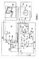
図1〜3にはこの発明の好ましき形態を棚テレビで示してあり、表示モニターは適宜形状の外側ケース12とビデオデータ表示用の表示スクリーン14と音響データを出力するスピーカー16とを有している。好ましき実施例においては、ビデオデータと音響データとは商品宣伝用の広告を含んでいる。図3に示すようにケース12はその裏面に取付けスタッド18を有している。これによりシステムを棚上に取り付けたり、またはデパートや商店などで提供する商品の近くに取り付けることができる。  1 to 3 show a preferred embodiment of the present invention by a shelf television, and the display monitor has anouter case 12 having a suitable shape, adisplay screen 14 for displaying video data, and aspeaker 16 for outputting acoustic data. is doing. In the preferred embodiment, the video data and audio data include advertising for product promotions. As shown in FIG. 3, thecase 12 has amounting stud 18 on the back surface thereof. As a result, the system can be mounted on a shelf or in the vicinity of a product provided in a department store or a store.

スタッド18はユニットを棚などへ取り付ける一形態を示すものに過ぎず、ブラケットや連結具などを適宜用いることが可能である。  Thestud 18 is merely a form for attaching the unit to a shelf or the like, and a bracket, a connector, or the like can be used as appropriate.

またシステムは期待される買手などの人間の表示システムへの接近を検知する近接検知器20を有しており、表示システムの近くに配置された商品に関連する広告メッセージを表示するべく表示システムが励動される。広告メッセージは買手の関心を惹くことを意図するものであり、商品に関連する情報を提供して買手がよりその商品の購買意欲を持つようにする。  The system also includes aproximity detector 20 that detects an approach to a human display system, such as an expected buyer, and the display system displays an advertising message related to a product located near the display system. Encouraged. The advertising message is intended to attract the buyer's interest and provides information related to the product so that the buyer is more willing to purchase the product.

近接センサー20はシステムの近くにおける人間の存在を検知してシステムを励動し、広告メッセージが、表示スクリーン14上に可視広告でまたスピーカー16から音響出力の形でシステムにより提供される。  Proximity sensor 20 senses the presence of a person in the vicinity of the system and energizes the system, and advertising messages are provided by the system in the form of a visual advertisement ondisplay screen 14 and in the form of sound output fromspeakers 16.

人間がシステムの近くに動いたときだけ広告が始まるので、広告が連続して表示されて人間の即座の関心を惹かない場合に比べて、人間が即座に広告に惹かれ易いのである。つまり人間は広告に、より注意を払うことになる。しかも広告は初めから上演され、したがって人間は広告の全てを見ることになり、販売に提供された商品に関連する完全なメッセージが提供され、人間のその商品に対する購買意欲が喚起されるのである。  Since the advertisement begins only when the person moves close to the system, the person is more likely to be immediately attracted to the advertisement than when the advertisement is displayed continuously and does not attract the immediate interest of the person. In other words, humans pay more attention to advertising. Moreover, the advertisement is staged from the beginning, so that the human will see all of the advertisement, provide a complete message related to the product offered for sale, and incentivize the person to purchase the product.

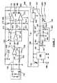
図4にシステム全体のブロック線図を、図5、6はその一部を示す。システムは検知器部30と高低音量制御器40とビデオ・音響制御部50とビデオ表示・音響出力部60とを有している。ビデオ表示・音響出力部60は基本的にはディスプレー14とスピーカー16とから構成されていて、それぞれ従来からある制御回路を具えているが説明は省く。  FIG. 4 shows a block diagram of the entire system, and FIGS. 5 and 6 show a part thereof. The system includes adetector unit 30, a high /low volume controller 40, a video /sound control unit 50, and a video display /sound output unit 60. The video display /sound output unit 60 is basically composed of thedisplay 14 and thespeaker 16 and each has a conventional control circuit, but a description thereof will be omitted.

ビデオ・音響制御部50はフラッシュカードやCDやテープまたは適宜な記憶媒体などの広告物が記憶されている媒体を有しており、データを読み出してビデオ信号や音響信号としてデータをビデオ表示・音響出力部60に供給する制御回路を具えている。それらは従来技術であるので詳細は省く。  The video /audio control unit 50 has a medium in which advertising matter such as a flash card, CD, tape, or an appropriate storage medium is stored. The data is read and displayed as a video signal or an audio signal. A control circuit for supplying to theoutput unit 60 is provided. Since they are conventional techniques, details are omitted.

システムへの人間の接近に反応して検知器部30はビデオ・音響制御部50とビデオ表示・音響出力部60とを励動し、かつ電源70を有している。該電源は12Vなどの電力を検知器部30に供給する。光感知レジスター71は電源70に並列接続されており、可変抵抗72は光感知レジスター71に直列接続されており、光感知レジスター71の感度を調節する。可変抵抗72と光感知レジスター71との間にはトランジスター73が接続されている。  In response to a human approach to the system, thedetector unit 30 excites the video /sound control unit 50 and the video display /sound output unit 60 and has a power source 70. The power source supplies power such as 12V to thedetector unit 30. Thephotosensitive register 71 is connected in parallel to the power supply 70, and thevariable resistor 72 is connected in series to thephotosensitive register 71, and adjusts the sensitivity of thephotosensitive register 71. Atransistor 73 is connected between thevariable resistor 72 and the lightsensitive register 71.

レジスター73のコレクターはライン74に接続され、かつレジスター79を介して電源70に接続されている。該ライン74はダイオード75と第2の可変抵抗76とを有している。コンデンサー77が可変抵抗76に接続されており、さらなるレジスター78はコンデンサー77と可変抵抗76とに接続されている。  The collector of theresistor 73 is connected to theline 74 and is connected to the power supply 70 via theresistor 79. Theline 74 has adiode 75 and a secondvariable resistor 76. Acapacitor 77 is connected to thevariable resistor 76, and afurther resistor 78 is connected to thecapacitor 77 and thevariable resistor 76.

レジスター78は第2のトランジスター80に接続され、該トランジスターのコレクターはライン81を介してリレー90に接続されている。このリレー90は電源70に接続され、かつダイオード91とスイッチ92とを有している。スイッチ92は閉じると電力を電源70からビデオ・音響制御部50に供給してビデオ・音響制御部50を励動・駆動する。  Resistor 78 is connected tosecond transistor 80, and the collector of the transistor is connected to relay 90 via line 81. Therelay 90 is connected to a power source 70 and has adiode 91 and aswitch 92. When theswitch 92 is closed, power is supplied from the power source 70 to the video /audio control unit 50 to excite and drive the video /audio control unit 50.

光の連続した強度が光感知レジスター71に入ると、可変抵抗72の設定に応じて電流が光感知レジスター71を通ってライン91に沿って流れる。かくしてトランジスター73がスイッチオンされ、電流がライン92に流れる。これによりトランジスター80がスイッチオフされて、リレー90には電流が流れない。かくしてリレースイッチ92は開いたままとなる。  When a continuous intensity of light enters thelight sensing resistor 71, current flows along theline 91 through thelight sensing resistor 71 according to the setting of thevariable resistor 72. Thus,transistor 73 is switched on and current flows throughline 92. As a result, thetransistor 80 is switched off and no current flows through therelay 90. Thus, therelay switch 92 remains open.

しかし光感知レジスター71に入射している光が、例えば2メートルの距離からシステムに近づいた人間により、遮断されると、光感知レジスター71は導通せず、トランジスター73はバイアスされずにオフとされる。ついでトランジスター80はダイオード75、可変抵抗76およびレジスター78を介して前バイアスされ、電流がリレー90に流れリレースイッチ92が閉じる。電力がスイッチ92を通って供給されライン93を介してビデオ・音響制御部50に至り、ビデオ・音響制御部50が励動されてビデオ・音響情報がビデオ表示・音響出力部60に記憶されてビデオ表示・音響出力部60により読出し・表示される。  However, if the light incident on the lightsensitive register 71 is interrupted by a person approaching the system from a distance of 2 meters, for example, the lightsensitive register 71 is not conducted, and thetransistor 73 is turned off without being biased. TheThe transistor 80 is then prebiased via thediode 75,variable resistor 76 andresistor 78, current flows through therelay 90 and therelay switch 92 closes. Electric power is supplied through theswitch 92 and reaches the video /audio control unit 50 via theline 93. The video /audio control unit 50 is excited and the video / audio information is stored in the video display /audio output unit 60. It is read out and displayed by the video display /sound output unit 60.

第2の可変抵抗76はリレー90をオンに保つ時間を設定する。光線が再び光感知レジスター71に入射すると(例えば人間がシステムから離れると)、リレーR2は励動を解除され、電力はビデオ・音響制御部50にオフとされる。  The secondvariable resistor 76 sets a time for keeping therelay 90 on. When the light beam enters thelight sensing register 71 again (for example, when a person leaves the system), the relay R2 is de-energized and the power is turned off to the video /audio controller 50.

図4に示すように、ビデオ・音響制御部50はビデオ表示・音響出力部60に直接接続されたビデオ出力ライン100を有している。ビデオ・音響制御部50からの音響出力ライン101は高低音量制御器40に接続されて、人間のシステムからの距離に応じて音量調節を行う。  As shown in FIG. 4, the video /audio control unit 50 has avideo output line 100 directly connected to a video display /audio output unit 60. Thesound output line 101 from the video /sound controller 50 is connected to the high /low volume controller 40 to adjust the volume according to the distance from the human system.

図4から明らかなように、ライン101は可変抵抗102に接続され、可変抵抗102は増幅器信号入力端103に接続されている。該入力端はビデオ表示・音響出力部60に接続されている。音響信号は高低音量制御器40を通って増幅器103に至り、ついでビデオ表示・音響出力部60に至ってスピーカー16を介して出力される。  As apparent from FIG. 4, theline 101 is connected to thevariable resistor 102, and thevariable resistor 102 is connected to the amplifiersignal input terminal 103. The input end is connected to the video display /sound output unit 60. The sound signal passes through the high /low volume controller 40 and reaches theamplifier 103, then reaches the video display /sound output unit 60 and is output via thespeaker 16.

電力が最初にビデオ・音響制御部50に供給されると、トランジスター73はオフ状態となり、高低音量制御器40のポイントAは浮いており、ビデオ・音響制御部50からの音響は可変抵抗102を介して直接増幅器103に至る。コンデンサー103aは徐々に充電され、充電時間は可変抵抗104により設定される。該可変抵抗はダイオード105と抵抗106を介してトランジスター107に接続されている。  When power is first supplied to the video /audio control unit 50, thetransistor 73 is turned off, the point A of the high /low volume controller 40 is floating, and the sound from the video /audio control unit 50 has thevariable resistor 102. To theamplifier 103 directly. The capacitor 103 a is gradually charged, and the charging time is set by thevariable resistor 104. The variable resistor is connected to thetransistor 107 via thediode 105 and theresistor 106.

MOSFETトランジスター107は徐々にオンにされ、可変抵抗102のポイントAを効果的にアースする。かくして一部の信号は、増幅器103には行かないで、ライン109を通ってアースされる。これにより信号ひいては音量が低減される。最終的な所望の音響レベルは可変抵抗102により設定できる。  MOSFET transistor 107 is gradually turned on, effectively grounding point A ofvariable resistor 102. Thus, some signals do not go toamplifier 103 but are grounded throughline 109. This reduces the signal and thus the volume. The final desired sound level can be set by thevariable resistor 102.

ビデオ・音響制御部50への電力がオフにされついで再びオンにされたときには、上記の過程が反復される。電力がスイッチオンされると、完全な音響信号がビデオ表示・音響出力部60に供給される。その後ある時間に亘って、低減された音響音量がビデオ表示・音響出力部60に供給されて、これによりスピーカー16から出力される音響信号の音量レベルが低減される。リレー90はリレースイッチ95、96を有しており、電力が供給されないときには、これらがライン111、112を介してコンデンサー103を放電する。したがってこれにより、電力が再びビデオ・音響制御部50に供給されたときに、反復可能な時間遅れが確実とされる。  When the power to the video /audio controller 50 is turned off and then turned on again, the above process is repeated. When the power is switched on, a complete audio signal is supplied to the video display /audio output unit 60. Thereafter, for a certain period of time, the reduced sound volume is supplied to the video display /sound output unit 60, whereby the volume level of the sound signal output from thespeaker 16 is reduced. Therelay 90 has relay switches 95 and 96, which discharge thecapacitor 103 via thelines 111 and 112 when power is not supplied. Thus, this ensures a repeatable time delay when power is again supplied to the video andaudio controller 50.

図7に示すのは他の実施例であり、熱分解・電気赤外線運動センサー150が人間の接近を検知する。人間がセンサー150の前を通り過ぎると、人体から発生される熱がセンサー150により検知され、センサー150は8ヘルツくらいの低周波数信号を発生する。これによりビデオ表示が始まる。センサー150の出力は増幅器151の非反転入力端にライン152により供給される。  FIG. 7 shows another embodiment, in which the thermal decomposition / electricinfrared motion sensor 150 detects the approach of a person. When a person passes in front of thesensor 150, heat generated from the human body is detected by thesensor 150, and thesensor 150 generates a low frequency signal of about 8 hertz. This starts video display. The output ofsensor 150 is provided byline 152 to the non-inverting input ofamplifier 151.

増幅器151はコンデンサー153、レジスター154、コンデンサー155およびレジスター156により構成される帯域パスフィルターに接続されている。帯域パスフィルターは8ヘルツくらいの帯域を有している。増幅器151は約30dbのゲインを提供する。増幅器151の出力端はコンデンサー161とレジスター162を介して増幅器160に接続されている。帯域パスフルター164は上記のものと同様に構成されており、増幅器160は他の30dbのゲインを提供する。  Theamplifier 151 is connected to a band pass filter including acapacitor 153, aresistor 154, acapacitor 155, and aresistor 156. The band pass filter has a band of about 8 Hz.Amplifier 151 provides a gain of about 30 db. The output terminal of theamplifier 151 is connected to theamplifier 160 via acapacitor 161 and aresistor 162.Bandpass filter 164 is configured similar to that described above, andamplifier 160 provides another 30 db gain.

増幅器160の出力端はコンデンサー167に接続されており、該コンデンサーは増幅器160からの信号を比較器169、170から構成されるウインドー比較回路168に供給する。該比較回路168のウインドー電圧は反転入力端については約3Vに、非反転入力端172については約1.7Vに設定される。  An output terminal of theamplifier 160 is connected to acapacitor 167, and the capacitor supplies a signal from theamplifier 160 to a window comparison circuit 168 includingcomparators 169 and 170. The window voltage of the comparison circuit 168 is set to about 3 V for the inverting input terminal and about 1.7 V for thenon-inverting input terminal 172.

人体の熱が検知されると、増幅器160が電圧出力を形成し、これがコンデンサー167に供給される。この電圧より外側の電圧はコンデンサー169の出力端173を低くさせ、これによりライン181を介してタイマー回路180が励動される。ライン181はダイオード182と183との間に接続され、これによりコンデンサー169、170からの出力は互いに孤立される。  When human body heat is detected,amplifier 160 creates a voltage output that is fed tocapacitor 167. A voltage outside this voltage causes theoutput 173 of thecapacitor 169 to go low, thereby energizing thetimer circuit 180 vialine 181.Line 181 is connected betweendiodes 182 and 183 so that the outputs fromcapacitors 169 and 170 are isolated from each other.

タイマー180の遅れ時間は可変抵抗185とコンデンサー186とにより設定される。遅れ時間はたとえば1分である。遅れ時間は可変抵抗185を調節することにより調節される。タイマー180がライン181上の信号により始動されると、出力端187は高くなり、これによりリレー188が励動される。これにより接点189が閉じ、電力が電源191からライン192へと供給される。ついで出力端193を介して図4に示すマルチメデイアボードに供給される。  The delay time of thetimer 180 is set by thevariable resistor 185 and thecapacitor 186. The delay time is, for example, 1 minute. The delay time is adjusted by adjusting thevariable resistor 185. Whentimer 180 is started by a signal online 181,output 187 goes high, thereby energizingrelay 188. As a result, thecontact 189 is closed, and power is supplied from thepower source 191 to theline 192. Then, it is supplied to the multimedia board shown in FIG.

接点190は開き、これによりコンデンサー195はレジスター196、197を介して充電される。レジスター196はMOSFET198をオンにするための時間を設定する。MOSFET198がオンになる前に、音響信号が音響入力端200から可変抵抗199に供給され、スライダー接点201を経て、前の実施例において信号増幅器103から供給される場合と同様に、音響入力端に供給される。  Contact 190 opens, causingcapacitor 195 to charge throughresistors 196, 197.Register 196 sets the time for turning onMOSFET 198. Before theMOSFET 198 is turned on, an acoustic signal is supplied from theacoustic input terminal 200 to thevariable resistor 199, and is supplied to the acoustic input terminal via theslider contact 201 as in the case of being supplied from thesignal amplifier 103 in the previous embodiment. Supplied.

コンデンサー195がMOSFET198を徐々にオンにするのに充分高い電位に充電されると、可変抵抗199が効果的にアースされて、音響信号が減衰される。かくして人間の検知により生成された当初の音響信号は可変抵抗199により設定され、コンデンサーC9が充電される。人間がテレビに接近しているとの仮定の下に音響信号は減衰される。人間がより近く来ると音量が減衰され、人間がテレビ12(図1参照)に近づくと心地よい音量が生成される。  Whencapacitor 195 is charged to a sufficiently high potential to gradually turn onMOSFET 198,variable resistor 199 is effectively grounded and the acoustic signal is attenuated. Thus, the initial acoustic signal generated by human detection is set by thevariable resistor 199, and the capacitor C9 is charged. The acoustic signal is attenuated under the assumption that a person is approaching the television. When a person comes closer, the volume is attenuated, and when a person approaches the television 12 (see FIG. 1), a comfortable volume is generated.

タイマー180の時間が一杯になったら、リレー188が励動を解かれて接点189が開く。したがってライン191からマルチメディアボードへの電力が遮断されて、ビデオ表示サイクルが終了する。接点190が閉じ、コンデンサー195がライン202を通って放電し、次のサイクルの音響レベル制御に備える。  Whentimer 180 is full,relay 188 is de-energized and contact 189 opens. Accordingly, the power fromline 191 to the multimedia board is cut off and the video display cycle ends. Contact 190 closes andcapacitor 195 discharges throughline 202 to prepare for sound level control in the next cycle.

電力供給回路205が12Vの入力供給を受け、この供給をライン206上に5Vの出力に変換し、ライン207を介してタイマー180を制御すべく供給して、可変抵抗185に電圧供給を行う。5Vの供給はライン208においても提供されて、レジスター209とコンデンサー210を介してセンサー150と比較器169、170を駆動する。ライン211はレジスター212、213、214を含んでおり、ライン215はレジスター216、217を含んでいる。  Thepower supply circuit 205 receives an input supply of 12V, converts this supply to an output of 5V on theline 206, supplies it to control thetimer 180 via theline 207, and supplies a voltage to thevariable resistor 185. A 5V supply is also provided online 208 to drivesensor 150 andcomparators 169, 170 throughresistor 209 and capacitor 210. Line 211 includesregisters 212, 213 and 214, andline 215 includesregisters 216 and 217.

図8に示す実施例においては、図7と同じ参照数字は同じ要素を示す。センサー300は熱分解・電気運動センサー集積回路である。センサー300は受動赤外線要素、増幅器および比較器出力回路を有している。人間がセンサー300を過ぎて歩くと、身体により発生された熱がセンサーにより検知され、低周波数信号が発生され、センサー300内の集積回路により増幅され、信号がセンサー300内の比較器回路に供給される。  In the embodiment shown in FIG. 8, the same reference numerals as in FIG. 7 indicate the same elements. Thesensor 300 is a pyrolysis / electric motion sensor integrated circuit. Thesensor 300 has a passive infrared element, an amplifier and a comparator output circuit. When a person walks past thesensor 300, the heat generated by the body is detected by the sensor, a low frequency signal is generated, amplified by an integrated circuit in thesensor 300, and the signal is fed to a comparator circuit in thesensor 300. Is done.

これにより比較器回路は高となり、高出力信号がライン301上でトランジスター302に供給され、トランジスターがスイッチオンされてライン303は低となる。ライン303上の低信号はライン304を介してタイマー180を励動する。この実施例においては、可変抵抗185は可変ではなくて、コンデンサー186とともに遅延タイマーを構成する。このタイマー180は前の実施例と同様にリレー188を駆動して、前記と同様に出力端193、200、201に出力を供給する。  This causes the comparator circuit to go high, providing a high output signal online 301 totransistor 302, which switches on andline 303 goes low. A low signal online 303 drivestimer 180 vialine 304. In this embodiment,variable resistor 185 is not variable and forms a delay timer withcapacitor 186. Thetimer 180 drives therelay 188 as in the previous embodiment, and supplies output to theoutput terminals 193, 200, 201 in the same manner as described above.

媒体ファイルが上演を始めると、マルチメディアカードからのライン310は高くなり、トランジスター311がオンにされる。これにより集積回路313のピン312は低となる。1個の媒体ファイルが完了すると、ライン310が状態を変えてライン312を高に引き上げる。回路313のアクティブ出力はディップスイッチ(dipswitch)314を介してトランジスター315に供給され、該トランジスターがトランジスター315をオンとする。これによりライン316は低となり、ライン181を介してのタイマーへの電力が遮断されてタイマーがリセットされ、メデイアプレーヤへの電力が遮断される。  When the media file begins to play,line 310 from the multimedia card goes high andtransistor 311 is turned on. This causes pin 312 ofintegrated circuit 313 to go low. When one media file is complete,line 310 changes state and pulls line 312 high. The active output of thecircuit 313 is supplied to thetransistor 315 via adipswitch 314, which turns on thetransistor 315. This causes line 316 to go low, power to the timer vialine 181 is cut off, the timer is reset, and power to the media player is cut off.

スイッチ314は遮断前に最大4個の媒体ファイルの上演を可能とする。コンデンサー317は遅延を導入して誤再始動を防止する。タイマー180が時間一杯になると、リレーが状態を変えて、接点A、Bが開き、前記のようにライン192を介しての媒体カードへの電力を遮断する。これによりビデオ表示が終了する。リレーの接点190が閉じて、コンデンサー195が放電し、次のサイクルの音響レベル制御に備える。  Switch 314 allows a maximum of four media files to be played before being blocked.Capacitor 317 introduces a delay to prevent false restarts. Whentimer 180 is full, the relay changes state and contacts A and B open and cut off power to the media card vialine 192 as described above. This ends the video display. Therelay contact 190 closes and thecapacitor 195 discharges, preparing for the next cycle of sound level control.

ディップスイッチ314は単一のまたは2個のまたは3個のまたは4個の広告の上演を可能とする。ディップスイッチは図8に示すひとつの位置に手動設定され、1、2、3または4個の広告が上演される(図8中に番号1、2、3、4で示す)。図8に示す位置では、1個の広告が上演される。ディップスイッチ304が図8中の位置4に調節されると、4個の広告全てが上演される。  Thedip switch 314 allows for the performance of a single or two or three or four advertisements. The dip switch is manually set to one position shown in FIG. 8, and 1, 2, 3 or 4 advertisements are played (indicated by numbers 1, 2, 3, 4 in FIG. 8). In the position shown in FIG. 8, one advertisement is performed. When thedip switch 304 is adjusted to position 4 in FIG. 8, all four advertisements are played.

タイマー180のオンタイムはライン181上の電力供給と可変抵抗185とコンデンサー186により構成されるR−C回路により設定される。例えば、オンタイムは最大5分として商品デモンストレーションなどのいかなる長い広告をも受容できるようにする。  The on-time of thetimer 180 is set by a power supply on theline 181 and an R-C circuit constituted by avariable resistor 185 and acapacitor 186. For example, the on-time can be up to 5 minutes to accept any long advertisements such as product demonstrations.

各広告の終りに、回路313は対応する図8のアクティブピン1〜4に高信号を出力する。いかなるときも1個だけのピンがアクティブとなる。ディップスイッチの設定により、高出力がディップスイッチ314により設定されたピンにおいて受け取られる。これによりトランジスター315は導通してライン306が低となる。ライン306上の低はタイマー180をリセットし、リレー188を解放する。ついでシステムは待機モードに入る。  At the end of each advertisement, thecircuit 313 outputs a high signal to the corresponding active pins 1-4 of FIG. Only one pin is active at any time. Due to the setting of the dip switch, a high output is received at the pin set by thedip switch 314. This causestransistor 315 to conduct andline 306 to go low. A low online 306 resetstimer 180 and releases relay 188. The system then enters standby mode.

リレー接点189が開くと、電力はライン320を介して回路321には供給されず媒体プレーヤ入力端322に行く。  Whenrelay contact 189 is opened, power is not supplied tocircuit 321 vialine 320 but goes to media player input 322.

図8の実施例においては、リレー188はレジスター351と発光ダイオード352に並列接続されていて、タイマー351の状態を示す。例えば発光ダイオードがリレーと同時にタイマー180から電力を供給され、タイマー180がリレー188に電力を供給すると発光ダイオードが発光する。  In the embodiment of FIG. 8, therelay 188 is connected in parallel to theresistor 351 and thelight emitting diode 352 to indicate the state of thetimer 351. For example, when the light emitting diode is supplied with power from thetimer 180 simultaneously with the relay, and thetimer 180 supplies power to therelay 188, the light emitting diode emits light.

この発明は電子工学の分野で広く利用されるものである。  The present invention is widely used in the field of electronics.

好ましき実施例における棚テレビの形での表示システムの前面図である。1 is a front view of a display system in the form of a shelf television in a preferred embodiment.図1のシステムの底面図である。FIG. 2 is a bottom view of the system of FIG.図1のシステムの後面図である。FIG. 2 is a rear view of the system of FIG.一実施例における表示システムのブロック線図である。It is a block diagram of the display system in one Example.図4の一部の詳細図である。FIG. 5 is a detailed view of a part of FIG. 4.図4の一部の詳細図であるFIG. 5 is a detailed view of a part of FIG. 4.この発明の他の実施例のブロック線図である。It is a block diagram of other Examples of this invention.最も好ましい実施例のブロック線図である。FIG. 2 is a block diagram of the most preferred embodiment.

符号の説明Explanation of symbols

12:ケース
14:表示スクリーン
20:近接センサー
30:検知器部
40:高低音量制御器
50:ビデオ・音響制御部
60:ビデオ表示・音響出力部
70:電源
90:リレー
12: Case 14: Display screen 20: Proximity sensor 30: Detector unit 40: High / low volume controller 50: Video / sound controller 60: Video display / sound output unit 70: Power supply 90: Relay

Claims (56)

Translated fromJapanese
表示システムであって、該システムにより表示されるべきデータを含んだデータ媒体と、該データを表示する表示スクリーンと、表示システム近くにおける人間の存在を検知してデータを表示スクリーン上に表示されるべくシステムを励動する近接センサーとを含んでなる表示システム。  A display system, a data medium containing data to be displayed by the system, a display screen for displaying the data, and detecting the presence of a human near the display system and displaying the data on the display screen And a proximity sensor for energizing the system. データ媒体と表示スクリーンとがテレビモニターとして形成されていることを特徴とする請求項1に記載のシステム。  The system of claim 1, wherein the data medium and the display screen are formed as a television monitor. 前記モニターがモニターを商店の棚上に取り付ける取付け手段を有していることを特徴とする請求項2に記載のシステム。  3. A system according to claim 2, wherein the monitor has mounting means for mounting the monitor on a store shelf. データ媒体がデータを含んだコンパクトディスク、フラッシュメモリー記憶素子または磁気テープを有していることを特徴とする請求項1に記載のシステム。  The system of claim 1, wherein the data medium comprises a compact disk, flash memory storage element or magnetic tape containing data. さらに音響データを出力する少なくとも1個のスピーカーと音響出力を比較的高い音量から比較的低い音量に変える人間のシステムへの接近を表わす高低音量制御器とを有していることを特徴とする請求項1に記載のシステム。  The system further comprises at least one speaker that outputs acoustic data and a high and low volume controller that represents an approach to a human system that changes the acoustic output from a relatively high volume to a relatively low volume. Item 4. The system according to Item 1. 制御器が所定の時間に亙って音量を比較的高い音量から比較的低い音量に変えることを特徴とする請求項5に記載のシステム。  6. The system of claim 5, wherein the controller changes the volume from a relatively high volume to a relatively low volume over a predetermined time. 近接センサーが光センサーであることを特徴とする請求項1に記載のシステム。  The system of claim 1, wherein the proximity sensor is an optical sensor. 光センサーが光感知レジスターであることを特徴とする請求項7に記載のシステム。  The system of claim 7, wherein the light sensor is a light sensitive register. センサーがスイッチ要素を操作し、該スイッチ要素がリレーを操作して電力をシステムに供給させてデータを表示すべくシステムを励動することを特徴とする請求項1に記載のシステム。  The system of claim 1, wherein the sensor operates a switch element, and the switch element operates a relay to power the system and display the data to display data. センサーが電源に並列に接続されて電流を第1のトランジスターに供給し、第2のトランジスターが電源に並列にかつリレーに直列に接続されており、第1のトランジスターが電源に接続されてセンサーが光を受けたときに電流が第1のトランジスターに供給されて、トランジスターをオンに切り換えて電流が第2のトランジスターに供給されないようにし、センサーが人間のシステムへの接近を示す少ない光を受けたときに、第1のトランジスターがオフに切り換えられて、該トランジスターが電流を第2のトランジスターに供給して第2のトランジスターをオンに切り換えリレーを励動してリレースイッチを閉じて、電力がシステムに供給されてデータ媒体がデータを出力して表示スクリーン上に表示させることを特徴とする請求項9に記載のシステム。  A sensor is connected in parallel to the power source to supply current to the first transistor, a second transistor is connected in parallel to the power source and in series with the relay, the first transistor is connected to the power source, and the sensor When light is received, current is supplied to the first transistor, switching the transistor on so that no current is supplied to the second transistor, and the sensor receives less light indicating an approach to the human system Sometimes the first transistor is switched off, the transistor supplies current to the second transistor, switches the second transistor on, energizes the relay, closes the relay switch, The data medium is supplied to and outputs data to be displayed on a display screen. Mounting system. さらにタイマー回路が設けられていて、システムに電力を維持して所定時間表示を維持することを特徴とする請求項1に記載のシステム。  The system according to claim 1, further comprising a timer circuit for maintaining power in the system and maintaining display for a predetermined time. 音量制御器が信号分割器を有しており、該分割器が増幅器の入力端に接続されており、該増幅器が少なくとも1個のスピーカーに音響信号を供給し、分割器がさらにトランジスターに接続されおり、充電要素が該トランジスターに接続されていて、充電要素が充電したときにトランジスターが徐々にオンにされて、信号分割器が増幅器に供給される信号の量を低減し、増幅器が少なくとも1個のスピーカーから出力される音響データの音量を低減することを特徴とする請求項5に記載のシステム。  The volume controller has a signal divider, which is connected to the input of the amplifier, the amplifier supplies an acoustic signal to at least one speaker, and the divider is further connected to a transistor. And the charging element is connected to the transistor, and when the charging element is charged, the transistor is gradually turned on so that the signal divider reduces the amount of signal supplied to the amplifier, and at least one amplifier The system according to claim 5, wherein the volume of acoustic data output from the speaker is reduced. 音量制御器が充電素子が充電する期間を設定するタイマーを有しており、トランジスターがオンにされて音量が比較的高い音量から比較的低い音量に変化する期間が設定されることを特徴とする請求項12に記載のシステム。  The volume controller has a timer for setting a period during which the charging element is charged, and the transistor is turned on to set a period during which the volume changes from a relatively high volume to a relatively low volume. The system of claim 12. 充電要素がコンデンサーであることを特徴とする請求項13に記載のシステム。  The system according to claim 13, wherein the charging element is a capacitor. 近接センサーが演算増幅器部分に接続されており、該増幅器は人間が検知されたときにセンサーから出力を受け、ウインドー比較器が増幅器からの出力を受けて制御出力を生じ、タイマー回路が該制御出力を受けてデータ媒体を励動する励動出力を与えて表示スクリーンに表示を行わしめるとともにデータを上演させ、所定の時間遅れ後にタイマー回路によりデータ媒体をスイッチオフして表示スクリーンとスピーカーにデータの表示と上演とを行わしめることを特徴とする請求項1に記載のシステム。  A proximity sensor is connected to the operational amplifier portion, the amplifier receives an output from the sensor when a human is detected, a window comparator receives the output from the amplifier and produces a control output, and a timer circuit generates the control output. In response, an excitation output for energizing the data medium is provided to display on the display screen and the data is staged. After a predetermined time delay, the data medium is switched off by a timer circuit, and the display screen and speakers are The system according to claim 1, wherein display and performance are performed. タイマー回路からの励動信号が減衰タイマー回路を励動して、ある時間に亙って音響データの音量の減衰を励動させることを特徴とする請求項15に記載のシステム。  16. The system of claim 15, wherein the excitation signal from the timer circuit activates the decay timer circuit to activate the attenuation of the volume of the acoustic data over a period of time. 減衰回路がコンデンサーおよび可変抵抗に接続された酸化金属半導体電界効果(MOSFET)トランジスターを有しており、可変抵抗が音響データを受ける入力端と音響データをスピーカーに供給する出力端とを有しており、コンデンサーが充電されると、MOSFETトランジスターが徐々にオンにされて可変抵抗をアースし、これにより可変抵抗の出力端に供給された音響信号の減衰が行われることを特徴とする請求項16に記載のシステム。  The attenuation circuit has a metal oxide semiconductor field effect (MOSFET) transistor connected to a capacitor and a variable resistor, and the variable resistor has an input that receives acoustic data and an output that supplies the acoustic data to a speaker 17. When the capacitor is charged, the MOSFET transistor is gradually turned on to ground the variable resistor, whereby the acoustic signal supplied to the output terminal of the variable resistor is attenuated. The system described in. データがさらに音響データを含んでおり、減衰タイマー回路がある時間に亙って音響データの音量を減衰し、タイマー回路が減衰タイマー回路を励動することを特徴とする請求項1に記載のシステム。  The system of claim 1, wherein the data further includes acoustic data, the decay timer circuit attenuates the volume of the acoustic data over time, and the timer circuit activates the decay timer circuit. . データが複数の分離した広告を含んでおり、広告タイマー回路が表示されるべき広告の数の信号表示を出力し、スイッチが表示されるべき広告の数に応じて広告回路の出力端を選択的に切り換えるとともにタイマーを切るべく信号を出力し、広告が表示された後で減衰回路を切ることを特徴とする請求項18に記載のシステム。  The data contains multiple separate advertisements, the advertisement timer circuit outputs a signal indication of the number of advertisements to be displayed, and the switch selectively selects the output end of the advertisement circuit according to the number of advertisements to be displayed 19. The system of claim 18, wherein a signal is output to switch to and the timer is turned off, and the attenuation circuit is turned off after the advertisement is displayed. スイッチの出力端がトランジスターに接続されており、該トランジスターはスイッチからの出力によりスイッチオンされてタイマー回路に所定の信号を供給してタイマー回路をリセットすることを特徴とする請求項19に記載のシステム。  20. The output terminal of the switch is connected to a transistor, and the transistor is switched on by an output from the switch to supply a predetermined signal to the timer circuit to reset the timer circuit. system. 減衰回路がコンデンサーとMOSFETトランジスターとを有しており、該トランジスターは可変抵抗に接続されており、可変抵抗が音響データを受ける入力端とスピーカーに音響データを供給する出力端とを有しており、コンデンサーが充電されると、MOSFETトランジスターが徐々にオンにされて可変抵抗をアースし、これにより可変抵抗の出力端に供給された音響信号の減衰が行われることを特徴とする請求項20に記載のシステム。  The attenuation circuit has a capacitor and a MOSFET transistor, and the transistor is connected to a variable resistor, and the variable resistor has an input terminal for receiving acoustic data and an output terminal for supplying acoustic data to a speaker. 21. The capacitor according to claim 20, wherein when the capacitor is charged, the MOSFET transistor is gradually turned on to ground the variable resistor, whereby the acoustic signal supplied to the output terminal of the variable resistor is attenuated. The described system. システムにより表示されかつ上演されるべきビデオデータと音響データとを含むためのデータ媒体と、データを表示・上演するための表示スクリーンおよび少なくとも1個のスピーカーと、表示システム近くにおける人間の存在を検知して少なくとも1個のスピーカーからの音響データ出力の音量を調節する近接センサーとを有してなる表示システム。  A data medium for containing video and audio data to be displayed and presented by the system, a display screen and at least one speaker for displaying and performing the data, and detecting the presence of a human near the display system And a proximity sensor for adjusting the volume of acoustic data output from at least one speaker. データ媒体と表示スクリーンとがテレビモニターとして形成されていることを特徴とする請求項22に記載のシステム。  The system according to claim 22, characterized in that the data medium and the display screen are formed as a television monitor. モニターがモニターを商店の棚に取り付ける取付け手段を有していることを特徴とする請求項23に記載のシステム。  24. The system of claim 23, wherein the monitor has attachment means for attaching the monitor to a store shelf. データ媒体がデータを含んだコンパクトディスク、フラシュメモリー記憶素子、磁気テープなどを含んでいることを特徴とする請求項22に記載のシステム。  23. The system of claim 22, wherein the data medium includes a compact disk containing data, a flash memory storage element, a magnetic tape, and the like. 近接センサーがタイマーを励動し、タイマーが所定時間に亙って音量を低減させ、その時間に亙って人間がよりシステムに近づくであろうとの仮定の上に音量が調節されることを特徴とする請求項22に記載のシステム。  Proximity sensor activates a timer, the timer reduces the volume over a predetermined time, and the volume is adjusted on the assumption that humans will be closer to the system over that time The system according to claim 22. 近接センサーが光センサーを含んでいることを特徴とする請求項22に記載のシステム。  23. The system of claim 22, wherein the proximity sensor includes an optical sensor. 光センサーが光検知レジスターであることを特徴とする請求項27に記載のシステム。  28. The system of claim 27, wherein the light sensor is a light detection register. 近接センサーが赤外線運動センサーであり、該運動センサーは人間がセンサーの近くにいるときに人体により発生される熱により励動されることを特徴とする請求項22に記載のシステム。  23. The system of claim 22, wherein the proximity sensor is an infrared motion sensor, and the motion sensor is excited by heat generated by the human body when the human is near the sensor. センサーがスイッチ要素を駆動し、該スイッチ要素がリレーを駆動してシステムを励動してデータを表示させるべく電力をシステムに供給させることを特徴とする請求項22に記載のシステム。  23. The system of claim 22, wherein the sensor drives a switch element that powers the system to drive a relay to excite the system and display data. 減衰タイマー回路が設けられていて、ある時間に亘って音響データの音量を減衰し、タイマー回路が減衰タイマー回路を励動することを特徴とする請求項22に記載のシステム。  23. The system of claim 22, wherein an attenuation timer circuit is provided to attenuate the volume of the acoustic data over a period of time, and the timer circuit activates the attenuation timer circuit. データが複数の分離した広告を含んでおり、広告タイマー回路が表示されるべき広告の数を表す信号を出力し、スイッチが表示されるべき広告の数に応じて広告回路の出力を選択的に切り換えかつタイマーをきる信号を出力し、これにより広告が表示された後で減衰回路を切ることを特徴とする請求項31に記載のシステム。  The data includes a plurality of separate advertisements, the advertisement timer circuit outputs a signal indicating the number of advertisements to be displayed, and the switch selectively outputs the advertisement circuit according to the number of advertisements to be displayed. 32. The system of claim 31, wherein the system outputs a signal to switch and a timer expires, thereby turning off the attenuation circuit after the advertisement is displayed. スイッチの出力端がトランジスターに接続されており、該トランジスターがスイッチからの出力によりスイッチオンされて所定の信号をタイマー回路に供給してタイマー回路をリセットすることを特徴とする請求項32に記載のシステム。  The output terminal of the switch is connected to a transistor, and the transistor is switched on by an output from the switch to supply a predetermined signal to the timer circuit to reset the timer circuit. system. 減衰回路がコンデンサーおよび可変抵抗に接続されたMOSFETトランジスターを有しており、可変抵抗が音響データを受ける入力端と音響データをスピーカーに供給する出力端とを有しており、コンデンサーが充電されると、MOSFETトランジスターが徐々にオンにされて可変抵抗をアースさせ、これにより可変抵抗の出力端に供給された音響信号の減衰を行わせることを特徴とする請求項33に記載のシステム。  The attenuation circuit has a MOSFET transistor connected to a capacitor and a variable resistor, and the variable resistor has an input terminal for receiving acoustic data and an output terminal for supplying acoustic data to the speaker, and the capacitor is charged. 34. The system of claim 33, wherein the MOSFET transistor is gradually turned on to ground the variable resistor, thereby attenuating the acoustic signal supplied to the output of the variable resistor. 広告を放送する広告装置であって、広告に関係しかつ音響データを含むデータを含んだデータ媒体と、音響データを出力する少なくとも1個のスピーカーと、音量設定制御器とを有してなり、該制御器はまずスピーカーにより放送される音響データの音量を比較的高い音量に設定し、ついで比較的低い音量に音量を低減することを特徴とする広告装置。  An advertising device for broadcasting an advertisement, comprising a data medium including data related to an advertisement and including acoustic data, at least one speaker for outputting acoustic data, and a volume setting controller, The controller first sets the volume of the acoustic data broadcast by the speaker to a relatively high volume, and then reduces the volume to a relatively low volume. さらに近接センサーが設けられていて、装置の近くにおける人間の存在を検知して、かつデータ媒体をしてユニットによる放送のためにデータを供給させることを特徴とする請求項35に記載の装置。  36. The apparatus of claim 35, further comprising a proximity sensor for detecting the presence of a human near the apparatus and providing a data medium for broadcast by the unit. 表示スクリーンが設けられており、データが表示スクリーン上に表示するためにビデオデータを含んでいることを特徴とする請求項35に記載の装置。  36. The apparatus of claim 35, wherein a display screen is provided and the data includes video data for display on the display screen. データ媒体と表示スクリーンとがテレビモニターとして形成されていることを特徴とする請求項37に記載の装置。  38. The device according to claim 37, wherein the data medium and the display screen are formed as a television monitor. モニターがモニターを商店の棚に取り付ける取付け手段を有していることを特徴とする請求項38に記載の装置。  39. The apparatus of claim 38, wherein the monitor has attachment means for attaching the monitor to a store shelf. データ媒体がデータを含んだコンパクトディスク、フラッシュメモリー記憶素子、磁気テープなどを有していることを特徴とする請求項35に記載の装置。  36. The apparatus of claim 35, wherein the data medium comprises a compact disk containing data, a flash memory storage element, a magnetic tape, or the like. 近接センサーが光センサーを有していることを特徴とする請求項36に記載の装置。  38. The apparatus of claim 36, wherein the proximity sensor comprises a light sensor. 光センサーが光感知レジスターであることを特徴とする請求項41に記載の装置。  42. The apparatus of claim 41, wherein the light sensor is a light sensitive resistor. センサーがスイッチ要素を駆動し、スイッチ要素がリレーを駆動してシステムを励動してデータを表示させるべく電力をシステムに供給させることを特徴とする請求項36に記載の装置。  37. The apparatus of claim 36, wherein the sensor drives a switch element, and the switch element drives a relay to energize the system to display data to display data. 近接センサーが赤外線運動センサーを有しており、該運動センサーが人間がセンサーの近くにいるときに人体により発生される熱により励動されることを特徴とする請求項36に記載の装置。  37. The apparatus of claim 36, wherein the proximity sensor comprises an infrared motion sensor, and the motion sensor is excited by heat generated by the human body when the person is near the sensor. センサーが電源に並列接続されて電流を第1のトランジスターに供給し、第2のトランジスターが電源に並列接続されるとともにリレーに直列接続されており、第1のトランジスターも電源に接続されており、センサーが光を受けると、電流が第1のトランジスターに供給されてトランジスターをスイッチオンし、電流は第2のトランジスターには供給されず、システムへの人間の接近を示すより少ない光をセンサーが受けると、第1のトランジスターがスイッチオフされて第2のトランジスターに電流を供給して第2のトランジスターをスイッチオンし、第2のトランジスターがリレーを励動してリレースイッチを閉じさせ、これにより電力がシステムに供給されてデータ媒体が表示スクリーン上での表示のためにデータを出力することを特徴とする請求項43に記載の装置。  A sensor is connected in parallel to the power source to supply current to the first transistor, a second transistor is connected in parallel to the power source and connected in series to the relay, and the first transistor is also connected to the power source, When the sensor receives light, current is supplied to the first transistor to switch on the transistor, current is not supplied to the second transistor, and the sensor receives less light indicating human approach to the system. And the first transistor is switched off to supply current to the second transistor to switch on the second transistor, and the second transistor excites the relay to close the relay switch, thereby Is supplied to the system and the data medium outputs data for display on the display screen. The apparatus of claim 43, symptoms. タイマー回路が設けられていてシステムへの電力を維持して、所定の時間に渡り表示を維持することを特徴とする請求項45に記載の装置。  46. The apparatus of claim 45, wherein a timer circuit is provided to maintain power to the system and maintain a display for a predetermined time. 音量制御器が信号分割器を有しており、信号分割器が少なくとも1個のスピーカーに音響信号を供給する増幅器入力端に接続されており、分割器もトランジスターに接続されており、充電要素がトランジスターに接続されており、これにより充電要素が充電したときに、トランジスターが徐々にオンにされて、信号分割器が信号の量を低減し、該信号は増幅器に供給されて少なくとも1個のスピーカーから出力される音響データの音量を低減することを特徴とする請求項35に記載の装置。  The volume controller has a signal divider, the signal divider is connected to an amplifier input that supplies an acoustic signal to at least one speaker, the divider is also connected to a transistor, and the charging element is Connected to the transistor, so that when the charging element is charged, the transistor is gradually turned on and the signal divider reduces the amount of signal, which is fed to the amplifier to at least one speaker 36. The apparatus according to claim 35, wherein the volume of the acoustic data output from the apparatus is reduced. 音量制御器が充電素子が充電する時間を設定するためのタイマーを有しており、トランジスターがオンとされて音量が比較的高い音量から比較的低い音量に変化する時間が設定されることを特徴とする請求項47に記載の装置。  The volume controller has a timer for setting the charging time of the charging element, and the time when the volume is changed from a relatively high volume to a relatively low volume when the transistor is turned on is set. 48. The apparatus of claim 47. 充電要素がコンデンサーであることを特徴とする請求項48に記載の装置。  49. The device of claim 48, wherein the charging element is a capacitor. 近接センサーが演算増幅器部分に接続されており、人間が検知されたときに該増幅器部分がセンサーからの出力を受け、ウインドー比較器が増幅器部分からの出力を受けて制御出力を形成し、タイマー回路が制御出力を受けてデータ媒体を励動する励動出力を与え、データ媒体が表示スクリーンにデータを表示しかつ上演するようにさせ、タイマー回路により設定される所定の時間遅れの後でデータ媒体がスイッチオフされて、データが表示スクリーンおよびスピーカーで表示・上演されることを特徴とする請求項36に記載の装置。  A proximity sensor is connected to the operational amplifier part, and when a human is detected, the amplifier part receives an output from the sensor, and a window comparator receives an output from the amplifier part to form a control output, and a timer circuit Receives a control output to provide an excitation output that excites the data medium, causing the data medium to display and stage the data on the display screen, and after the predetermined time delay set by the timer circuit 37. The apparatus of claim 36, wherein is switched off and data is displayed and presented on a display screen and speakers. タイマー回路からの励動信号が減衰タイマー回路を励動して、ある時間に亘って音響データの音量を減衰させることを特徴とする請求項50に記載の装置。  51. The apparatus of claim 50, wherein the excitation signal from the timer circuit activates the decay timer circuit to attenuate the volume of the acoustic data over a period of time. 減衰回路がコンデンサーとMOSFETトランジスターを有しており、該トランジスターが可変抵抗に接続されており、可変抵抗が音響データを受ける入力端とスピーカーに音響データを供給する出力端とを有しており、コンデンサーが充電するとMOSFETトランジスターが徐々にオンにされて可変抵抗をアースし、これにより可変抵抗の出力端に供給される音響信号が減衰されることを特徴とする請求項51に記載の装置。  The attenuation circuit has a capacitor and a MOSFET transistor, the transistor is connected to a variable resistor, and the variable resistor has an input terminal for receiving acoustic data and an output terminal for supplying acoustic data to a speaker. 52. The apparatus of claim 51, wherein when the capacitor is charged, the MOSFET transistor is gradually turned on to ground the variable resistor, thereby attenuating the acoustic signal supplied to the output terminal of the variable resistor. 制御器が減衰タイマー回路を有しており、該タイマー回路がある時間に亘って音響データの音量を減衰し、タイマー回路が減衰タイマー回路を励動することを特徴とする請求項35に記載の装置。  36. The controller of claim 35, wherein the controller includes an attenuation timer circuit, the timer circuit attenuates the volume of the acoustic data over a period of time, and the timer circuit activates the attenuation timer circuit. apparatus. データが複数の分離した広告を含んでおり、広告タイマー回路が表示されるべき広告の数を表す信号を出力し、スイッチが表示されるべき広告の数に応じて広告回路の出力に選択的に切り換わり、信号が出力されてタイマーが切られ、広告が表示された後で減衰回路が切られることを特徴とする請求項53に記載の装置。  The data includes a plurality of separate advertisements, the advertisement timer circuit outputs a signal indicating the number of advertisements to be displayed, and the switch selectively selects the output of the advertisement circuit according to the number of advertisements to be displayed. 54. The apparatus of claim 53, wherein the attenuation circuit is turned off after switching, a signal is output, the timer is turned off, and the advertisement is displayed. スイッチの出力端がトランジスターに接続されており、トランジスターがスイッチからの出力端によりスイッチオンされて所定の信号をタイマー回路に供給してタイマー回路をリセットすることを特徴とする請求項54に記載の装置。  The output terminal of the switch is connected to a transistor, and the transistor is switched on by the output terminal from the switch to supply a predetermined signal to the timer circuit to reset the timer circuit. apparatus. 減衰回路がコンデンサーとMOSFETトランジスターとを有しており、該トランジスターが可変抵抗に接続されており、該可変抵抗が音響データを受ける入力端と音響データをスピーカーに供給する出力端とを有しており、コンデンサーが充電すると、MOSFETトランジスターが徐々にオンにされて可変抵抗をアースし、これにより可変抵抗の出力端に供給される音響信号が減衰されることを特徴とする請求項55に記載の装置。  The attenuation circuit has a capacitor and a MOSFET transistor, the transistor is connected to a variable resistor, and the variable resistor has an input terminal for receiving acoustic data and an output terminal for supplying acoustic data to a speaker. 56. The method of claim 55, wherein when the capacitor is charged, the MOSFET transistor is gradually turned on to ground the variable resistor, thereby attenuating the acoustic signal supplied to the output terminal of the variable resistor. apparatus.
JP2006545301A2003-12-162004-12-15 Display systemPendingJP2007514206A (en)

Applications Claiming Priority (3)

Application NumberPriority DateFiling DateTitle
MYPI20034822MY135196A (en)2003-12-162003-12-16A display system
AU2004901901AAU2004901901A0 (en)2004-04-07A display system
PCT/SG2004/000414WO2005059874A1 (en)2003-12-162004-12-15A display system

Publications (1)

Publication NumberPublication Date
JP2007514206Atrue JP2007514206A (en)2007-05-31

Family

ID=34701664

Family Applications (1)

Application NumberTitlePriority DateFiling Date
JP2006545301APendingJP2007514206A (en)2003-12-162004-12-15 Display system

Country Status (7)

CountryLink
JP (1)JP2007514206A (en)
KR (1)KR101086897B1 (en)
AU (1)AU2004300112B2 (en)
EG (1)EG24481A (en)
NZ (1)NZ547934A (en)
TW (1)TW200527335A (en)
WO (1)WO2005059874A1 (en)

Families Citing this family (28)

* Cited by examiner, † Cited by third party
Publication numberPriority datePublication dateAssigneeTitle
KR101086897B1 (en)2003-12-162011-11-25유-마케이팅 인터렉추얼 프로퍼티즈 피티이 엘티디 Display system
US10339495B2 (en)2004-02-032019-07-02Rtc Industries, Inc.System for inventory management
US9898712B2 (en)2004-02-032018-02-20Rtc Industries, Inc.Continuous display shelf edge label device
US9818148B2 (en)2013-03-052017-11-14Rtc Industries, Inc.In-store item alert architecture
US8938396B2 (en)2004-02-032015-01-20Rtc Industries, Inc.System for inventory management
US20110044582A1 (en)2009-08-212011-02-24Microsoft CorporationEfficient collimation of light with optical wedge
US8354806B2 (en)2009-08-212013-01-15Microsoft CorporationScanning collimation of light via flat panel lamp
TWI411987B (en)*2009-10-292013-10-11Au Optronics CorpDisplay capable of adjusting display luminance in response to a distance between a user and a panel
CN101930704B (en)*2010-08-052012-07-04宋四海Information release terminal device with human body-sensing display
CN102074177A (en)*2010-10-192011-05-25上海仙视电子有限公司Intelligent volume control advertising machine
US9201185B2 (en)2011-02-042015-12-01Microsoft Technology Licensing, LlcDirectional backlighting for display panels
US20130027772A1 (en)2011-07-272013-01-31Microsoft CorporationVariable-depth stereoscopic display
US9354748B2 (en)2012-02-132016-05-31Microsoft Technology Licensing, LlcOptical stylus interaction
US9870066B2 (en)2012-03-022018-01-16Microsoft Technology Licensing, LlcMethod of manufacturing an input device
US9075566B2 (en)2012-03-022015-07-07Microsoft Technoogy Licensing, LLCFlexible hinge spine
US9460029B2 (en)2012-03-022016-10-04Microsoft Technology Licensing, LlcPressure sensitive keys
US8873227B2 (en)2012-03-022014-10-28Microsoft CorporationFlexible hinge support layer
ITBO20120256A1 (en)*2012-05-092013-11-10Bonfante Eddo S N C Di Bonfante Dino & C EXHIBITION SYSTEM FOR URBAN FURNITURE
US8947353B2 (en)2012-06-122015-02-03Microsoft CorporationPhotosensor array gesture detection
US9256089B2 (en)2012-06-152016-02-09Microsoft Technology Licensing, LlcObject-detecting backlight unit
US8964379B2 (en)2012-08-202015-02-24Microsoft CorporationSwitchable magnetic lock
US10357118B2 (en)2013-03-052019-07-23Rtc Industries, Inc.Systems and methods for merchandizing electronic displays
JP2014182332A (en)*2013-03-212014-09-29Casio Comput Co LtdSignage device
US9552777B2 (en)2013-05-102017-01-24Microsoft Technology Licensing, LlcPhase control backlight
US10120420B2 (en)2014-03-212018-11-06Microsoft Technology Licensing, LlcLockable display and techniques enabling use of lockable displays
US10324733B2 (en)2014-07-302019-06-18Microsoft Technology Licensing, LlcShutdown notifications
US11182738B2 (en)2014-11-122021-11-23Rtc Industries, Inc.System for inventory management
US11109692B2 (en)2014-11-122021-09-07Rtc Industries, Inc.Systems and methods for merchandizing electronic displays

Citations (4)

* Cited by examiner, † Cited by third party
Publication numberPriority datePublication dateAssigneeTitle
JPH0934424A (en)*1995-07-211997-02-07Mitsubishi Electric Corp Display system
JP2000152109A (en)*1998-11-112000-05-30Matsushita Electric Ind Co Ltd TV receiver
JP2001134225A (en)*1999-08-262001-05-18Toppan Printing Co Ltd Advertising providing device and storage medium for the advertising providing device, exhibit, display panel, display case
JP2005049656A (en)*2003-07-292005-02-24Nec Plasma Display CorpDisplay system and position conjecture system

Family Cites Families (9)

* Cited by examiner, † Cited by third party
Publication numberPriority datePublication dateAssigneeTitle
CH673345A5 (en)*1987-07-311990-02-28Grosfo Ag
US4912457A (en)*1988-12-211990-03-27Ladd ElectronicsDetector and message annunciator device
GB2248001A (en)*1990-09-111992-03-18Concourse Communications LtdControlling sound volume in dependence on ambient noise
JP2870395B2 (en)*1993-12-271999-03-17日本電気株式会社 Stereophonic sound reproducer
US5657004A (en)*1995-04-111997-08-12Felknor International, Inc.Electronically controlled point of purchase display
US5966696A (en)*1998-04-141999-10-12InfovationSystem for tracking consumer exposure and for exposing consumers to different advertisements
US6572020B2 (en)*2001-10-312003-06-03Symbol Technologies, Inc.Retail sales cutomer auto-ID activation
DE10237315A1 (en)*2002-08-152004-02-26Segerer, JürgenMultimedia poster for advertising purposes combines printed information with computer controlled video or sound information
KR101086897B1 (en)2003-12-162011-11-25유-마케이팅 인터렉추얼 프로퍼티즈 피티이 엘티디 Display system

Patent Citations (4)

* Cited by examiner, † Cited by third party
Publication numberPriority datePublication dateAssigneeTitle
JPH0934424A (en)*1995-07-211997-02-07Mitsubishi Electric Corp Display system
JP2000152109A (en)*1998-11-112000-05-30Matsushita Electric Ind Co Ltd TV receiver
JP2001134225A (en)*1999-08-262001-05-18Toppan Printing Co Ltd Advertising providing device and storage medium for the advertising providing device, exhibit, display panel, display case
JP2005049656A (en)*2003-07-292005-02-24Nec Plasma Display CorpDisplay system and position conjecture system

Also Published As

Publication numberPublication date
TW200527335A (en)2005-08-16
WO2005059874A1 (en)2005-06-30
KR20060123497A (en)2006-12-01
HK1098566A1 (en)2007-07-20
KR101086897B1 (en)2011-11-25
WO2005059874A8 (en)2006-01-26
EG24481A (en)2009-08-09
AU2004300112A1 (en)2005-06-30
NZ547934A (en)2009-05-31
AU2004300112B2 (en)2009-09-03

Similar Documents

PublicationPublication DateTitle
JP2007514206A (en) Display system
US8650073B2 (en)Glasses-free 3D advertising system and method
US5923252A (en)Audio/visual marketing device and marketing system
US5097981A (en)Point-of-purchase coupon dispenser
US20090037945A1 (en)Multimedia presentation apparatus, method of selecting multimedia content, and computer program product
US5966696A (en)System for tracking consumer exposure and for exposing consumers to different advertisements
JP5109055B2 (en) System having an electronic advertising terminal
US20100191651A1 (en)System and method for securing and displaying items for merchandising
WO2020077096A1 (en)Systems, method and apparatus for automated inventory interaction
US7119804B2 (en)Point-of-sale marketing material presence and viewability verification system and method
KR20090001680A (en) Centralized advertising system and method
US11321735B2 (en)Method and device for controlling the issuing of product-related advertising messages to customers in sales facilities
US5671331A (en)Printed publication vending apparatus including programmable announcement capability
JPH0830218A (en)Price display device by illumination and voice
HK1098566B (en)A display system
CN100504972C (en) a display system
KR20050116192A (en)Advertising-contents providing method
US20170337801A1 (en)Electronic Reminder Device
CN222354457U (en)System for providing purchase incentives
CN210896539U (en)Commodity sales promotion device
CN210896538U (en)Commodity sales promotion sound production device
KR950010476B1 (en)Automatic greeting system for advertisement
WO2020241460A1 (en)Management server, device, and distribution method
JP2010097154A (en)Image display device for advertizement with number of person measuring function
KR200287724Y1 (en)Manless voice advertising apparatus

Legal Events

DateCodeTitleDescription
A621Written request for application examination

Free format text:JAPANESE INTERMEDIATE CODE: A621

Effective date:20071116

RD02Notification of acceptance of power of attorney

Free format text:JAPANESE INTERMEDIATE CODE: A7422

Effective date:20100315

A521Request for written amendment filed

Free format text:JAPANESE INTERMEDIATE CODE: A523

Effective date:20100805

A131Notification of reasons for refusal

Free format text:JAPANESE INTERMEDIATE CODE: A131

Effective date:20101129

A02Decision of refusal

Free format text:JAPANESE INTERMEDIATE CODE: A02

Effective date:20110425


[8]ページ先頭

©2009-2025 Movatter.jp