JP2007512092A - Devices and methods for attaching soft tissue to bone - Google Patents
Devices and methods for attaching soft tissue to boneDownload PDFInfo
- Publication number
- JP2007512092A JP2007512092AJP2006541350AJP2006541350AJP2007512092AJP 2007512092 AJP2007512092 AJP 2007512092AJP 2006541350 AJP2006541350 AJP 2006541350AJP 2006541350 AJP2006541350 AJP 2006541350AJP 2007512092 AJP2007512092 AJP 2007512092A
- Authority
- JP
- Japan
- Prior art keywords
- tissue
- bone
- anchor
- core
- grasping member
- Prior art date
- Legal status (The legal status is an assumption and is not a legal conclusion. Google has not performed a legal analysis and makes no representation as to the accuracy of the status listed.)
- Pending
Links
- 210000000988bone and boneAnatomy0.000titleclaimsabstractdescription74
- 210000004872soft tissueAnatomy0.000titleclaimsabstractdescription53
- 238000000034methodMethods0.000titleclaimsabstractdescription23
- 210000001519tissueAnatomy0.000claimsabstractdescription121
- 239000000463materialSubstances0.000claimsdescription5
- RTAQQCXQSZGOHL-UHFFFAOYSA-NTitaniumChemical compound[Ti]RTAQQCXQSZGOHL-UHFFFAOYSA-N0.000claimsdescription3
- 229920002988biodegradable polymerPolymers0.000claimsdescription3
- 239000004621biodegradable polymerSubstances0.000claimsdescription3
- 229910001000nickel titaniumInorganic materials0.000claimsdescription3
- 239000010936titaniumSubstances0.000claimsdescription3
- 229910052719titaniumInorganic materials0.000claimsdescription3
- HLXZNVUGXRDIFK-UHFFFAOYSA-Nnickel titaniumChemical compound[Ti].[Ti].[Ti].[Ti].[Ti].[Ti].[Ti].[Ti].[Ti].[Ti].[Ti].[Ni].[Ni].[Ni].[Ni].[Ni].[Ni].[Ni].[Ni].[Ni].[Ni].[Ni].[Ni].[Ni].[Ni]HLXZNVUGXRDIFK-UHFFFAOYSA-N0.000claimsdescription2
- 238000004873anchoringMethods0.000claims1
- 229910001220stainless steelInorganic materials0.000claims1
- 239000010935stainless steelSubstances0.000claims1
- 230000001054cortical effectEffects0.000description8
- 230000035876healingEffects0.000description3
- 210000003041ligamentAnatomy0.000description3
- 229920001432poly(L-lactide)Polymers0.000description3
- JVTAAEKCZFNVCJ-REOHCLBHSA-NL-lactic acidChemical compoundC[C@H](O)C(O)=OJVTAAEKCZFNVCJ-REOHCLBHSA-N0.000description2
- 230000006378damageEffects0.000description2
- 230000001627detrimental effectEffects0.000description2
- 238000005553drillingMethods0.000description2
- JVTAAEKCZFNVCJ-UHFFFAOYSA-Nlactic acidChemical compoundCC(O)C(O)=OJVTAAEKCZFNVCJ-UHFFFAOYSA-N0.000description2
- 239000000203mixtureSubstances0.000description2
- 238000011477surgical interventionMethods0.000description2
- 208000005137Joint instabilityDiseases0.000description1
- 229910045601alloyInorganic materials0.000description1
- 239000000956alloySubstances0.000description1
- 210000001264anterior cruciate ligamentAnatomy0.000description1
- 230000001684chronic effectEffects0.000description1
- 238000004140cleaningMethods0.000description1
- 238000010276constructionMethods0.000description1
- 229920001577copolymerPolymers0.000description1
- 238000006073displacement reactionMethods0.000description1
- 230000006870functionEffects0.000description1
- 238000003780insertionMethods0.000description1
- 230000037431insertionEffects0.000description1
- 230000008407joint functionEffects0.000description1
- 210000003127kneeAnatomy0.000description1
- 210000000629knee jointAnatomy0.000description1
- 229960000448lactic acidDrugs0.000description1
- 230000013011matingEffects0.000description1
- 229910052751metalInorganic materials0.000description1
- 239000002184metalSubstances0.000description1
- 210000003205muscleAnatomy0.000description1
- 229920000747poly(lactic acid)Polymers0.000description1
- 239000004626polylactic acidSubstances0.000description1
- 229920000642polymerPolymers0.000description1
- 238000011084recoveryMethods0.000description1
- 210000000513rotator cuffAnatomy0.000description1
- 210000000323shoulder jointAnatomy0.000description1
- 230000000472traumatic effectEffects0.000description1
- 238000012800visualizationMethods0.000description1
Images


Classifications
- A—HUMAN NECESSITIES
- A61—MEDICAL OR VETERINARY SCIENCE; HYGIENE
- A61B—DIAGNOSIS; SURGERY; IDENTIFICATION
- A61B17/00—Surgical instruments, devices or methods
- A61B17/064—Surgical staples, i.e. penetrating the tissue
- A61B17/0642—Surgical staples, i.e. penetrating the tissue for bones, e.g. for osteosynthesis or connecting tendon to bone
- A—HUMAN NECESSITIES
- A61—MEDICAL OR VETERINARY SCIENCE; HYGIENE
- A61F—FILTERS IMPLANTABLE INTO BLOOD VESSELS; PROSTHESES; DEVICES PROVIDING PATENCY TO, OR PREVENTING COLLAPSING OF, TUBULAR STRUCTURES OF THE BODY, e.g. STENTS; ORTHOPAEDIC, NURSING OR CONTRACEPTIVE DEVICES; FOMENTATION; TREATMENT OR PROTECTION OF EYES OR EARS; BANDAGES, DRESSINGS OR ABSORBENT PADS; FIRST-AID KITS
- A61F2/00—Filters implantable into blood vessels; Prostheses, i.e. artificial substitutes or replacements for parts of the body; Appliances for connecting them with the body; Devices providing patency to, or preventing collapsing of, tubular structures of the body, e.g. stents
- A61F2/02—Prostheses implantable into the body
- A61F2/08—Muscles; Tendons; Ligaments
- A61F2/0805—Implements for inserting tendons or ligaments
- A—HUMAN NECESSITIES
- A61—MEDICAL OR VETERINARY SCIENCE; HYGIENE
- A61F—FILTERS IMPLANTABLE INTO BLOOD VESSELS; PROSTHESES; DEVICES PROVIDING PATENCY TO, OR PREVENTING COLLAPSING OF, TUBULAR STRUCTURES OF THE BODY, e.g. STENTS; ORTHOPAEDIC, NURSING OR CONTRACEPTIVE DEVICES; FOMENTATION; TREATMENT OR PROTECTION OF EYES OR EARS; BANDAGES, DRESSINGS OR ABSORBENT PADS; FIRST-AID KITS
- A61F2/00—Filters implantable into blood vessels; Prostheses, i.e. artificial substitutes or replacements for parts of the body; Appliances for connecting them with the body; Devices providing patency to, or preventing collapsing of, tubular structures of the body, e.g. stents
- A61F2/02—Prostheses implantable into the body
- A61F2/08—Muscles; Tendons; Ligaments
- A61F2/0811—Fixation devices for tendons or ligaments
- A—HUMAN NECESSITIES
- A61—MEDICAL OR VETERINARY SCIENCE; HYGIENE
- A61B—DIAGNOSIS; SURGERY; IDENTIFICATION
- A61B17/00—Surgical instruments, devices or methods
- A61B17/064—Surgical staples, i.e. penetrating the tissue
- A61B17/0643—Surgical staples, i.e. penetrating the tissue with separate closing member, e.g. for interlocking with staple
- A—HUMAN NECESSITIES
- A61—MEDICAL OR VETERINARY SCIENCE; HYGIENE
- A61B—DIAGNOSIS; SURGERY; IDENTIFICATION
- A61B17/00—Surgical instruments, devices or methods
- A61B17/064—Surgical staples, i.e. penetrating the tissue
- A61B2017/0647—Surgical staples, i.e. penetrating the tissue having one single leg, e.g. tacks
- A—HUMAN NECESSITIES
- A61—MEDICAL OR VETERINARY SCIENCE; HYGIENE
- A61F—FILTERS IMPLANTABLE INTO BLOOD VESSELS; PROSTHESES; DEVICES PROVIDING PATENCY TO, OR PREVENTING COLLAPSING OF, TUBULAR STRUCTURES OF THE BODY, e.g. STENTS; ORTHOPAEDIC, NURSING OR CONTRACEPTIVE DEVICES; FOMENTATION; TREATMENT OR PROTECTION OF EYES OR EARS; BANDAGES, DRESSINGS OR ABSORBENT PADS; FIRST-AID KITS
- A61F2/00—Filters implantable into blood vessels; Prostheses, i.e. artificial substitutes or replacements for parts of the body; Appliances for connecting them with the body; Devices providing patency to, or preventing collapsing of, tubular structures of the body, e.g. stents
- A61F2/02—Prostheses implantable into the body
- A61F2/08—Muscles; Tendons; Ligaments
- A61F2/0811—Fixation devices for tendons or ligaments
- A61F2002/0817—Structure of the anchor
- A61F2002/0823—Modular anchors comprising a plurality of separate parts
- A61F2002/0835—Modular anchors comprising a plurality of separate parts with deformation of anchor parts, e.g. expansion of dowel by set screw
- A—HUMAN NECESSITIES
- A61—MEDICAL OR VETERINARY SCIENCE; HYGIENE
- A61F—FILTERS IMPLANTABLE INTO BLOOD VESSELS; PROSTHESES; DEVICES PROVIDING PATENCY TO, OR PREVENTING COLLAPSING OF, TUBULAR STRUCTURES OF THE BODY, e.g. STENTS; ORTHOPAEDIC, NURSING OR CONTRACEPTIVE DEVICES; FOMENTATION; TREATMENT OR PROTECTION OF EYES OR EARS; BANDAGES, DRESSINGS OR ABSORBENT PADS; FIRST-AID KITS
- A61F2/00—Filters implantable into blood vessels; Prostheses, i.e. artificial substitutes or replacements for parts of the body; Appliances for connecting them with the body; Devices providing patency to, or preventing collapsing of, tubular structures of the body, e.g. stents
- A61F2/02—Prostheses implantable into the body
- A61F2/08—Muscles; Tendons; Ligaments
- A61F2/0811—Fixation devices for tendons or ligaments
- A61F2002/0847—Mode of fixation of anchor to tendon or ligament
- A61F2002/0852—Fixation of a loop or U-turn, e.g. eyelets, anchor having multiple holes
- A—HUMAN NECESSITIES
- A61—MEDICAL OR VETERINARY SCIENCE; HYGIENE
- A61F—FILTERS IMPLANTABLE INTO BLOOD VESSELS; PROSTHESES; DEVICES PROVIDING PATENCY TO, OR PREVENTING COLLAPSING OF, TUBULAR STRUCTURES OF THE BODY, e.g. STENTS; ORTHOPAEDIC, NURSING OR CONTRACEPTIVE DEVICES; FOMENTATION; TREATMENT OR PROTECTION OF EYES OR EARS; BANDAGES, DRESSINGS OR ABSORBENT PADS; FIRST-AID KITS
- A61F2/00—Filters implantable into blood vessels; Prostheses, i.e. artificial substitutes or replacements for parts of the body; Appliances for connecting them with the body; Devices providing patency to, or preventing collapsing of, tubular structures of the body, e.g. stents
- A61F2/02—Prostheses implantable into the body
- A61F2/08—Muscles; Tendons; Ligaments
- A61F2/0811—Fixation devices for tendons or ligaments
- A61F2002/0847—Mode of fixation of anchor to tendon or ligament
- A61F2002/0858—Fixation of tendon or ligament between anchor and bone, e.g. interference screws, wedges
- A—HUMAN NECESSITIES
- A61—MEDICAL OR VETERINARY SCIENCE; HYGIENE
- A61F—FILTERS IMPLANTABLE INTO BLOOD VESSELS; PROSTHESES; DEVICES PROVIDING PATENCY TO, OR PREVENTING COLLAPSING OF, TUBULAR STRUCTURES OF THE BODY, e.g. STENTS; ORTHOPAEDIC, NURSING OR CONTRACEPTIVE DEVICES; FOMENTATION; TREATMENT OR PROTECTION OF EYES OR EARS; BANDAGES, DRESSINGS OR ABSORBENT PADS; FIRST-AID KITS
- A61F2/00—Filters implantable into blood vessels; Prostheses, i.e. artificial substitutes or replacements for parts of the body; Appliances for connecting them with the body; Devices providing patency to, or preventing collapsing of, tubular structures of the body, e.g. stents
- A61F2/02—Prostheses implantable into the body
- A61F2/08—Muscles; Tendons; Ligaments
- A61F2/0811—Fixation devices for tendons or ligaments
- A61F2002/0847—Mode of fixation of anchor to tendon or ligament
- A61F2002/0864—Fixation of tendon or ligament between anchor elements, e.g. by additional screws in the anchor, anchor crimped around tendon
- A—HUMAN NECESSITIES
- A61—MEDICAL OR VETERINARY SCIENCE; HYGIENE
- A61F—FILTERS IMPLANTABLE INTO BLOOD VESSELS; PROSTHESES; DEVICES PROVIDING PATENCY TO, OR PREVENTING COLLAPSING OF, TUBULAR STRUCTURES OF THE BODY, e.g. STENTS; ORTHOPAEDIC, NURSING OR CONTRACEPTIVE DEVICES; FOMENTATION; TREATMENT OR PROTECTION OF EYES OR EARS; BANDAGES, DRESSINGS OR ABSORBENT PADS; FIRST-AID KITS
- A61F2/00—Filters implantable into blood vessels; Prostheses, i.e. artificial substitutes or replacements for parts of the body; Appliances for connecting them with the body; Devices providing patency to, or preventing collapsing of, tubular structures of the body, e.g. stents
- A61F2/02—Prostheses implantable into the body
- A61F2/08—Muscles; Tendons; Ligaments
- A61F2/0811—Fixation devices for tendons or ligaments
- A61F2002/0876—Position of anchor in respect to the bone
- A61F2002/0888—Anchor in or on a blind hole or on the bone surface without formation of a tunnel
Landscapes
- Health & Medical Sciences (AREA)
- Life Sciences & Earth Sciences (AREA)
- Orthopedic Medicine & Surgery (AREA)
- Veterinary Medicine (AREA)
- Rheumatology (AREA)
- Public Health (AREA)
- General Health & Medical Sciences (AREA)
- Engineering & Computer Science (AREA)
- Biomedical Technology (AREA)
- Heart & Thoracic Surgery (AREA)
- Animal Behavior & Ethology (AREA)
- Oral & Maxillofacial Surgery (AREA)
- Vascular Medicine (AREA)
- Transplantation (AREA)
- Cardiology (AREA)
- Rehabilitation Therapy (AREA)
- Surgery (AREA)
- Nuclear Medicine, Radiotherapy & Molecular Imaging (AREA)
- Medical Informatics (AREA)
- Molecular Biology (AREA)
- Surgical Instruments (AREA)
Abstract
Translated fromJapaneseDescription
Translated fromJapanese本発明は医療デバイスに関し、より詳細には軟組織を骨に付着させるためのデバイスおよび方法に関する。 The present invention relates to medical devices, and more particularly to devices and methods for attaching soft tissue to bone.
軟組織を骨に付着(または再付着)させるためのいくつかのデバイスおよび方法が知られている。これらのデバイスおよび方法は、多くの場合、靱帯を含む軟組織が断裂しまたはそれ以外で付着していた骨から剥離する、肩や膝などに関する比較的一般的な傷害に対応して開発されてきた。そのような傷害は、しばしば外科的インターベンションを要する慢性的な関節の不安定性を招く。 Several devices and methods are known for attaching (or reattaching) soft tissue to bone. These devices and methods have been developed in response to relatively common injuries, such as shoulders and knees, where soft tissue, including ligaments, often ruptures or otherwise detaches from bone that was otherwise attached . Such injuries often result in chronic joint instability that requires surgical intervention.
外科的インターベンションは従来、カメラおよび外科用デバイスを中に通すカニューレ
を使用し修復部位で使用される関節鏡デバイスの使用を含む。これらの方法およびデバイスは、低外傷性用、および患者の回復時間を短くするために設計されてきた。Surgical intervention conventionally involves the use of an arthroscopic device that is used at the repair site using a camera and a cannula through which the surgical device passes. These methods and devices have been designed for low traumatic use and to reduce patient recovery time.
カメラなどの視覚化デバイスのほかに、カニューレを通して、剥離した軟組織を骨に再付着させる様々な器具が開発されてきた。剥離した組織を骨に付着させるために、様々なアンカーが考案されてきた。特定の一手法では、アンカーを骨内部へ挿入することを含む。縫合糸を取り付けた、または縫合糸をアンカーに取り付けるための手段を有するアンカーを挿入する。縫合糸を剥離した組織に連結し、組織と骨を接触させるように締め付ける。やがて組織および骨は自然治癒過程を経て再付着する。 In addition to visualization devices such as cameras, various instruments have been developed to reattach detached soft tissue to bone through a cannula. Various anchors have been devised to attach exfoliated tissue to bone. One particular approach involves inserting an anchor into the bone. An anchor having a means for attaching the suture or attaching the suture to the anchor is inserted. The suture is connected to the exfoliated tissue and tightened to bring the tissue and bone into contact. Over time, tissues and bones reattach through a natural healing process.
しかし、このような方法には欠点がある。そのような欠点の1つは、外科医が、組織を骨に付着させるために縫合糸を頻繁に使用しなければならないことである。別の欠点は、「引き強度」が所望するよりも低い場合が多いことである。「引き強度」とはアンカーを取り付けていた骨から引き寄せるのに必要な力であると定性的に定義される。さらに別の欠点は、「切断強度」に関する。上述のように、従来技術の多くは縫合糸を利用しており、このことが別の潜在的弱点を招く。「切断強度」は縫合糸を切断するのに必要な力であると定性的に定義される。従来技術のさらに別の欠点は、外科医が、特定し剥離した軟組織を再付着位置に移動するために1つのデバイスを使用し、組織を実際に付着させるために第2の器具またはデバイスを使用しなければならないことである。適切な治癒および治癒後の関節の機能を得るために、再付着時の組織の伸長程度または張度は正確でなければならないので、このことは特に有害である。したがって、外科医は靱帯上の張力量を再付着の直前に調整できなければならない。配置の際に2つの異なるデバイスを使用しなければならず、そのため手術時間が長くなり、組織再付着時にエラーが起こる機会が一般に高くなる可能性がある。 However, this method has drawbacks. One such drawback is that surgeons must frequently use sutures to attach tissue to bone. Another disadvantage is that the “pull strength” is often lower than desired. “Pulling strength” is qualitatively defined as the force required to pull from an anchored bone. Yet another drawback relates to "cut strength". As mentioned above, much of the prior art utilizes sutures, which introduces another potential weakness. “Cut strength” is qualitatively defined as the force required to cut a suture. Yet another disadvantage of the prior art is that the surgeon uses one device to move the identified and detached soft tissue to the reattachment position and uses a second instrument or device to actually attach the tissue. It must be. This is particularly detrimental because the extent or tonicity of the tissue upon reattachment must be accurate in order to obtain proper healing and post-healing joint function. Therefore, the surgeon must be able to adjust the amount of tension on the ligament just prior to reattachment. Two different devices must be used during placement, which can increase surgical time and generally increase the chance of errors during tissue reattachment.
さらに他のデバイスでは、組織が動くことおよび固定されることの両方が可能であるが、骨にあらかじめドリリングした穴の中で使用する前に組織を切削または穿孔することよってのみ、そのようにできる。そのようなデバイスは組織を突き刺しまたは引っ掻くので有害であり、張力を簡単に調節することができない。 In still other devices, the tissue can be both moved and fixed, but only by cutting or drilling the tissue prior to use in a hole previously drilled into the bone. . Such devices are detrimental because they pierce or scratch tissue and tension cannot be easily adjusted.
本発明は軟組織を骨に付着させるためのデバイス、システムおよび方法を含む。本システムによって、外科医は組織を骨に再付着させる際に2つの異なる目的を達成することが可能になる。このシステムによって、組織を把持および操作して適切な組織の位置および組織への張力を実現すること、また所望の位置および張力が実現された後で組織を骨に付着させることが可能になる。システムは、アンカーデバイスおよびデリバリーデバイスを含む。アンカーデバイスは、最も単純な実施形態ではアンカーおよびコアを含む。アンカーは基部および基部から延び内向きに付勢された2つの向かい合う組織把持部材から構成され、各組織把持部材は、弛緩し内向きに付勢された位置、一部が拡張された中間位置、および拡張されたロック位置を有する。組織把持部材は、弛緩し内向きに付勢された位置と中間位置の間で近接可能に拡張可能である。コアは中央の軸方向開口を有し、アンカー内部に配設されており、組織把持部材の内向きに付勢された位置に対応する近位側位置と組織把持部材の拡張されたロック位置に対応する遠位側位置の間で可動である。 The present invention includes devices, systems and methods for attaching soft tissue to bone. The system allows a surgeon to achieve two different purposes in reattaching tissue to bone. This system allows the tissue to be grasped and manipulated to achieve the proper tissue location and tension on the tissue, and the tissue to attach to the bone after the desired location and tension has been achieved. The system includes an anchor device and a delivery device. The anchor device includes an anchor and a core in the simplest embodiment. The anchor is composed of a base and two opposing tissue gripping members extending from the base and biased inwardly, each tissue gripping member in a relaxed and inward biased position, a partially expanded intermediate position, And having an extended locking position. The tissue grasping member is expandable to be proximate between a relaxed and inwardly biased position and an intermediate position. The core has a central axial opening and is disposed within the anchor and in a proximal position corresponding to the inwardly biased position of the tissue grasping member and an expanded locked position of the tissue grasping member. It is movable between corresponding distal positions.
本発明はまた、2つの向かい合う組織把持部材の間に軟組織の一部を把持するステップ、組織把持部材を軟組織の把持した部分と共に骨内の穴の中へと挿入するステップ、挿入された穴の中で組織把持部材を拡張することによってデバイスを固定するステップを含む、組織を骨に再付着させる方法を含む。この方法は、好ましくは、組織把持部材を拡張させる遠位側位置へとコアを前進させるステップを含む。 The invention also includes grasping a portion of soft tissue between two opposing tissue grasping members, inserting the tissue grasping member into a hole in the bone with the grasped portion of the soft tissue, A method of reattaching tissue to bone, including securing the device by expanding a tissue grasping member therein. The method preferably includes advancing the core to a distal position where the tissue grasping member is expanded.
本発明の特徴は新規であると考えられ、本発明の特徴的な要素は添付の特許請求の範囲に独自性が記載されている。図は説明のためのものに過ぎず、正確な縮尺では描かれていない。ただし本発明自体は、構成および操作方法の両方に関して、添付の図面と併せて以下の詳細な説明を参照すれば最も良く理解することができる。 The features of the invention are believed to be novel and the distinctive elements of the invention are set forth with particularity in the appended claims. The figures are for illustration only and are not drawn to scale. However, the invention itself may best be understood with reference to the following detailed description in conjunction with the accompanying drawings, both in terms of construction and method of operation.
本発明は、軟組織を骨に再付着させるためのデバイス、システムおよび方法を含む。ヒトや動物の体内では組織と骨が結合した多くの場所があるが、本発明は特に、前十字靱帯の再建あるいは肩の転位または回旋腱板筋の剥離の修復など、肩または膝関節の修復に良く適している。 The present invention includes devices, systems and methods for reattaching soft tissue to bone. Although there are many places where tissue and bone are combined in the human or animal body, the present invention specifically addresses shoulder or knee joint repair, such as reconstruction of the anterior cruciate ligament or repair of shoulder displacement or rotator cuff muscle detachment. Well suited for.
一般に、本発明は組織上での適切な位置および張力、ならびに所望の位置および張力が実現された後で組織を骨に再付着することを実現するように、組織を把持および操作することを可能にするアンカーデバイスを含む。アンカーデバイスは、最も単純な実施形態ではアンカーおよびコアを含む。アンカーは基部および基部から延び内向きに付勢された2つの向かい合う組織把持部材から構成され、各組織把持部材は、弛緩し内向きに付勢された位置、一部が拡張された中間位置、および拡張されたロック位置を有する。組織把持部材は、弛緩し内向きに付勢された位置と中間位置の間で近接可能に拡張可能である。コアは中央の軸方向開口を有し、アンカー内部に配設されており、組織把持部材の内向きに付勢された位置に対応する近位側位置と組織把持部材の拡張されたロック位置に対応する遠位側位置の間で可動である。 In general, the present invention allows the tissue to be grasped and manipulated to achieve the proper position and tension on the tissue, and reattaching the tissue to the bone after the desired position and tension is achieved Including anchor device. The anchor device includes an anchor and a core in the simplest embodiment. The anchor is composed of a base and two opposing tissue gripping members extending from the base and biased inwardly, each tissue gripping member in a relaxed and inward biased position, a partially expanded intermediate position, And having an extended locking position. The tissue grasping member is expandable to be proximate between a relaxed and inwardly biased position and an intermediate position. The core has a central axial opening and is disposed within the anchor and in a proximal position corresponding to the inwardly biased position of the tissue grasping member and an expanded locked position of the tissue grasping member. It is movable between corresponding distal positions.
図1〜3は、本発明によるアンカーデバイスの例示的な実施形態を示している。図1は、基部101が内向きに付勢された2つの向かい合う組織把持部材105および106を支持するアンカー100の断面図を示す。図1の各組織把持部材105および106は、弛緩し内向きに付勢された位置にあり、組織を把持する近位端110および111はもう少しで接触する状態である。遠位端110と111は、それらの間に間隔がある場合、使用時に組織を把持するのに十分小さいものである限り、接触している必要はない。この態様は後段でより詳細に説明する。 1-3 show an exemplary embodiment of an anchor device according to the present invention. FIG. 1 shows a cross-sectional view of an
図2はコア200が中に配設されたアンカー100を示す。コア200は、その中心を通るように配設された中央軸方向開口210を有する。開口の目的は後段でより詳細に説明する。図1に示すように、図2は、弛緩し内向きに付勢された位置にある把持部材105および106を示す。 FIG. 2 shows the
図3は、コア200を、組織把持部材105および106を拡張されたロック位置にロックする遠位側位置へと遠位側に動かした後の図である。図3では、コア200の雌型溝300が組織把持部材105および106の内面からの雄型突起310を受けることが示されている。図3に示すように、ずれまたは過挿入に対する追加的な保護のために、組織把持部材105および106の内面上の雌型溝320と対合するコア200からの雄型突起330を使用することもできる。ただし、アンカー100内のコア200を固定するためには1つの雄型/雌型対合しか必要としないことに留意されたい。 FIG. 3 is a view after the
図4は、組織把持部材105および106が、弛緩し内向きに付勢された位置で、互いに直径方向に配設されるような角度からアンカー100を示す。骨係合部材410、411、412および413もまた、組織把持部材105および106の各側にそれぞれ2つずつ示されている。骨係合部材410、411、412および413は、組織把持近位端110および111を有する組織把持部材105および106が骨係合部材410、411、412および413の遠位側の大部分を越えて延びている限り、基部101から遠位側に延びない。これらの骨係合部材の機能については、後段でより詳細に記述する。 FIG. 4 shows the
アンカーおよびコアは、アンカーに使用される材料が非拡張位置と拡張位置の間で動くことを可能にするのに十分柔軟である限り、多くの様々な材料から作製することができる。好ましくは、アンカーデバイスはチタンまたは他の適切な生体適合性金属または合金から作製される。より好ましくは、デバイスはニチノール(ニッケル−チタン合金)から作製される。あるいは、デバイスはポリ乳酸ベースのコポリマーなど生分解性ポリマーから作製することができる。これらの生分解性ポリマーのなかで好ましいものは、ポリ(L−乳酸)(PLLA)およびポリ(DL−乳酸)(PDLLA)である。より好ましいものはこれらのポリマーの混合であり、70%PDLLA/30%PLLAの混合を含む。 The anchor and core can be made from many different materials as long as the material used for the anchor is flexible enough to allow it to move between the unexpanded and expanded positions. Preferably, the anchor device is made from titanium or other suitable biocompatible metal or alloy. More preferably, the device is made from nitinol (nickel-titanium alloy). Alternatively, the device can be made from a biodegradable polymer, such as a polylactic acid-based copolymer. Among these biodegradable polymers, poly (L-lactic acid) (PLLA) and poly (DL-lactic acid) (PDLLA) are preferable. More preferred is a blend of these polymers, including a blend of 70% PDLLA / 30% PLLA.
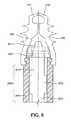
本発明のアンカーデバイスの例示的な実施形態を適切なデリバリーデバイスと併せて以下に説明する。図5Aはデリバリーデバイス500の端部に脱着可能に取り付けられたアンカー100およびコア200を示す。このデリバリーデバイス500の特定の実施形態は、遠位端506、アプリケータ505内部に摺動可能および脱着可能に同軸に配設されたプッシュロッド510を有する、アプリケータ505から構成される。本実施形態では、プッシュロッド510は3つの部分、すなわち遠位端511、中央部分512および近位側シャフト513を有する。中央部分512は近位側シャフト513より直径が大きい。このように直径が違う理由は、後段でより詳細に説明する。2つのデリバリーデバイス要素(アプリケータ505およびプッシュロッド510)はそれぞれ、図5Aでは点線で示す共通中央軸に沿って、他方の要素に対して長手方向に摺動可能である。 Exemplary embodiments of the anchor device of the present invention are described below in conjunction with a suitable delivery device. FIG. 5A shows
アプリケータ505の遠位端506は中央軸に向かって内向きに付勢される構造であり、プッシュロッドの中央部分512が図5Aに示すように配設されている限り、プッシュロッドの中央部分512がアプリケータの遠位端506に対して外向き力を加えるようになっている。図5Aでは、アプリケータの遠位端506がプッシュロッドの中央部分512によって付勢に対して外向きに押し付けられるとき、アンカー100の基部101の雌型溝が雄型突起を受けるように、アプリケータの遠位端506がその円周上に雄型突起507および509を含むことが示されている。 The
図5Bはアプリケータ505の遠位端506を示す。本実施形態では、4つの雄型突起507、508、509および510が遠位端506を含むことを示す。この構成によって、雄型突起が径方向に動くことが可能になる。図8に例を示し、より詳細に後述するが、このように動くことによってアンカーデバイス100の解除が可能になる。 FIG. 5B shows the
図5Aはまた、組織把持部材105および106を、弛緩し内向きに付勢された位置から部分的に拡張された中間位置へと部分的に拡張する、プッシュロッドの遠位端511を示す。図5Aでは、プッシュロッド505が近位側にわずかに動くと組織把持部材105と106が一緒になるように、または図に示した位置からわずかに遠位側に動くとさらに離れるように動くことを示している。これはプッシュロッドの遠位端511が先細状であるために起こる。この段階でこのような動きがなされる間、コア200は中央軸方向開口210によってプッシュロッド505の動きが可能であるので基本的に静止したままであることにも留意されたい。 FIG. 5A also shows pushrod
図6は、拡張している組織把持部材105および106が中間位置から、弛緩し内向きに付勢された位置へと閉じるように、プッシュロッド505を図5Aに示す位置から近位側に動かした状態を示す。上述の雄型/雌型対合によってアプリケータ505の遠位端506上の定位置でアンカー100をまだ保持するように、プッシュロッドの中央部分512はアプリケータの遠位端506を外向きにまだ押し付けていることに留意されたい。 FIG. 6 shows that the
図7は、プッシュロッド510を図5Aに示した位置を越えて遠位側に動かした後で起こることを示しており、プッシュロッドの中央部分512の遠位端がコア200の近位端と接触するようになっている。この点でプッシュロッド510をさらに近位側に動かすと、コア200はロック位置の状態に向かって遠位側に動く。図8はコア200がロック位置にあり、拡張している組織把持部材105および106が完全に拡張したロック位置にあることを示す。ここではコア200および組織把持部材105および106内面の上の対応する溝および突起はそれぞれ、コア200をロック位置に維持するように働くことに留意されたい。 FIG. 7 shows what happens after the
図8はまた、プッシュロッドの中央部分512の近位端がアプリケータ505の遠位端506を過ぎて動くときに起こることも示している。具体的には、アプリケータ遠位端506が付勢下で内向きに動かされ、アプリケータ遠位端506の雄型突起がアンカー100の基部101の雌型溝から外れるように動き、アンカー100をアプリケータから解除するようになっている。この点でアプリケータ505およびプッシュロッド510を取り外すことができる。 FIG. 8 also shows what happens when the proximal end of the push rod
さらにプッシュロッド510は、3つの一般的な位置、すなわち(1)組織把持部材105および106が閉じたまたは弛緩した内向きに付勢された位置に対応する近位側位置(図6)、(2)組織把持部材105および106の中間位置に対応する中間位置(図5Aおよび7)、(3)組織把持部材105および106の拡張したロック位置(図8)の間で可動である。コア200は、例えば図5Aおよび7に示すように中間位置にあるときは動くことも動かないこともできるが、図8に示すようにコア200を最終的なロック位置へと押し付けるのに十分な距離だけプッシュロッド510を遠位側に動かすと、ロック位置へと動く。 Further, the
図9〜21は本発明による方法を示す。図9は、骨910に付着している正常な軟組織900の一部を示す。軟組織900が皮質骨930の層と接触する、組織の内方成長領域920が示されている。海綿骨940(皮質骨より柔らかい)が、皮質骨930の下に部分的に示されている。図10は皮質骨930から剥離した軟組織900を示す。 9-21 show the method according to the invention. FIG. 9 shows a portion of normal
部位にアクセスした後で組織を修復する第1のステップは、外科医がドリリングのための骨表面領域を清浄し準備することによって行われる。図11は、図12に示す穴951を形成するように、皮質骨930および海綿骨940を穿通するドリル950を示す。ドリル刃の種類、およびドリル950で罹患領域にアクセスする方法は、当業者には良く知られている。このステップで重要なことは、穴951が適切な深さまで穿孔されることを確実にすることである。後でより明確に示すが、アンカー100は、アンカー100が穴951に押し付けられる軟組織900と共に効果的に拡張することができるように十分な深さまで骨910を穿通しなければならない。 The first step of repairing tissue after accessing the site is performed by the surgeon cleaning and preparing the bone surface area for drilling. FIG. 11 shows a
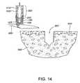
図13は次のステップ、すなわちデリバリーデバイス500の遠位端に配設された、アンカー100およびコア200から構成されるアンカーデバイスで、軟組織900を集めるステップを示す。外科医は、修復が所望される軟組織900を特定し、次いで図13に示すように組織把持部材105および106を、弛緩し閉じた位置から中間の組織把持位置へと開く。この点でコア200は動いていないことに留意されたい。 FIG. 13 illustrates the next step, collecting
次に、外科医はプッシュロッド510を近位側に動かすことによって軟組織900を把持し、それにより図14に示すように組織把持部材105および106を軟組織900の周りで内向きに付勢された力によって接近させることができる。このことにより外科医は、穴951内に挿入するための準備において組織を動かし、かつ他の操作をすることができる。 Next, the surgeon grasps the
次いで、外科医は、図15に示すように軟組織900を穴951の上に配置するように、把持された軟組織900、アンカーデバイス100、コア200およびデリバリーデバイス500を操作する。軟組織900を穴951の上に引き寄せると、軟組織はそれを締め付け、さらには延ばすこともできる力を受ける。外科医は様々な方法で、張りの程度を制御することができる。そのような方法の一部を後段でより詳細に述べる。 The surgeon then manipulates the grasped
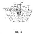
外科医が軟組織900の一片を固定することを決定した後、外科医は、図16に示すようにシステムを穴951内部へと下げることができる。図17は図16の一部の拡大図である。図18は固定の初期段階でプッシュロッド510を進めていることを示す。この点でプッシュロッド510を遠位側に動かし、それにより組織把持部材が外向きに動き始める。まずプッシュロッド510の遠位端が組織把持部材105および106を拡張させるが、プッシュロッド510が十分に遠位側に動くと、コアロッド200が組織把持部材105および106を離すように押し付ける。これは図18に当てはまり、コア200がロック位置に向かって動くにつれて組織把持部材105および106が拡張し始めるように、プッシュロッド510を十分に遠位側に進めていることを示している。海綿骨940は柔らかいのでアンカー100は海綿骨940に対して開口することができ、それにより軟組織900を穴951の壁を越えて拡張させることに留意されたい。 After the surgeon decides to fix a piece of
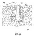
図19は、外科医が、コア200をそのロック位置へと押し付けるのに十分な点まで、プッシュロッド510を遠位側に進めた結果を示す。図19は、組織把持部材105および106の内面の雄型突起を受けている雌型溝を備えたコア200を示す。またプッシュロッド510の中央部分512がアプリケータ505の遠位端506を過ぎて動いたので、アプリケータ505の遠位端506の雄型突起507および509が、ここでは内向き位置にあることも示している。 FIG. 19 shows the result of the surgeon moving the
図20はアプリケータ500を修復部位から近位側に引き抜くと起こることを示している。アンカー100およびコア200は、軟組織900を海綿骨940および皮質骨930内に保持しながら定位置にとどまっている。図21は、患者の体内に残るものを示している。治癒のための期間が過ぎると、軟組織900は正常な組織内方成長によって皮質骨930に再結合する。 FIG. 20 illustrates what happens when the
図4の実施形態に示すように、棘150が、アンカー100を骨内部で固定する助けとなる。これらの棘はまた、好ましくは骨係合部材410、411、412および413上にある。図5Aの実施形態は、組織把持部材105および106のそれぞれにそのような棘150が3つあることを示す。図5Aの断面図には示されていないが、このような棘はまた、好ましくは骨係合部材の上にある。棘の数は好ましくは1つから5つであるが、追加の棘を使用することもできる。 As shown in the embodiment of FIG. 4,
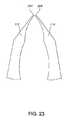
一実施形態ではまた、組織把持部材の遠位側先端の内面に歯が含まれている。図22は、歯221を有する遠位側先端110および111の拡大図を示す。本発明と一致する他の構成も想定することができる。図23は、歯はないが組織を把持するための尖った遠位端223を使用する、一組の先端を示す。 In one embodiment, teeth are also included on the inner surface of the distal tip of the tissue grasping member. FIG. 22 shows an enlarged view of
上述のように、外科医は、特に靱帯の再付着の場合は、組織を骨内部に固定する前に、軟組織の「張度」を調節することができることが好ましい。これは多くの方法によって行うことができるが、そのうちのいくつかを以下に述べる。 As noted above, it is preferred that the surgeon be able to adjust the “tension” of the soft tissue prior to securing the tissue within the bone, especially in the case of ligament reattachment. This can be done in many ways, some of which are described below.
外科医は、最初に軟組織の一片を把持した後、組織を骨に準備した穴内部に挿入する前に、組織を締め付けるために中央軸の周りでデバイス全体をねじりまたはそれを回転することができる。このことは図24に示されている。 The surgeon may first grasp a piece of soft tissue and then twist or rotate the entire device around the central axis to tighten the tissue before inserting the tissue into the prepared hole in the bone. This is illustrated in FIG.
あるいは、外科医は、軟組織を把持し、動かし、穴の中に部分的に挿入し、次いで組織を解除し、追加の組織を再度把持するためにデバイスを動かし直し、その組織を最初に挿入した組織の上に再度挿入することができる。これを、穴の外側に残る軟組織に所望の張力が得られるまで、継続することができる。 Alternatively, the surgeon grasps and moves the soft tissue, partially inserts it into the hole, then releases the tissue, moves the device again to re- grasp the additional tissue, and inserts the tissue first Can be inserted again on top. This can be continued until the desired tension is obtained in the soft tissue remaining outside the hole.
段階的に張力を増加するさらに別の方法には、上述のものと同様であるが第2のアンカーデバイスを含むシステムがある。この実施形態では、図25に示すように、頭部805およびシャフト810を有するプラグ800を最初においたアンカーデバイス内に押し付けることができる。この実施形態では、プラグ800をコア200の中央軸方向開口210内部に単純に摩擦嵌合し、軟組織900内部で圧縮することによって定位置に保持する。プラグ800は、チタンまたは上述の生分解性材料を含むどのような適切な材料によって作製することもできる。この実施形態は、プラグ800を挿入する前に軟組織をコア200の開口の上に引き寄せるための追加の器具を必要とする。この方法はまた、プラグ800を定位置に押すための追加の器具も必要とする。そのようなプラグの配置に使用するための方法および器具は、当業者には既知である。 Yet another method of incrementally increasing tension is a system similar to that described above, but including a second anchor device. In this embodiment, a
所望の張力を得るためのさらに別の方法は、上述のように軟組織の一片を穴の中に固定し、デリバリーデバイスを除去し、より多くの組織を締め付けまたは集めながら2回およびそれ以上の工程を繰り返すように、第2のアンカーデバイスと共に戻すことである。このような場合、組織を挿入するたびに異なる穴の中に挿入することができる。あるいは、コア200は中央が開口しているので、段階的により小さいアンカーデバイスを使用してそれぞれを最後に置いたアンカーデバイスの中に挿入することができる。このようなシステムが図26に示されている。図26は第2のアンカー260およびアンカーシステム内部に配設された第2のコア270を示す。 Yet another way to obtain the desired tension is to fix a piece of soft tissue in the hole as described above, remove the delivery device, and tighten and collect more tissue twice and more steps To return with the second anchor device. In such cases, each time tissue is inserted, it can be inserted into a different hole. Alternatively, since the
以上、本発明をいくつかの好ましい実施形態に関して記載したが、本発明の全範囲は添付の特許請求の範囲によって確認されたい。 Although the invention has been described with reference to several preferred embodiments, the full scope of the invention should be ascertained from the claims that follow.
100 アンカー
101 基部
105 組織把持部材
106 組織把持部材
110 近位端
111 近位端
200 コア
210 中央軸方向開口
221 歯
223 遠位端
300 雌型溝
320 雌型溝
330 雄型突起
410 骨係合部材
411 骨係合部材
412 骨係合部材
413 骨係合部材
500 デリバリーデバイス
505 アプリケータ
506 遠位端
507 雄型突起
508 雄型突起
509 雄型突起
510 プッシュロッド
511 遠位端
512 中央部分
513 近位側シャフト
900 軟組織
910 骨
920 内方成長領域
930 皮質骨
940 海綿骨
950 ドリル
951 穴
DESCRIPTION OF
Claims (17)
Translated fromJapanese中央の軸方向開口を有し、前記アンカー内部に配設されており、前記組織把持部材の前記内向きに付勢された位置に対応する近位側位置と前記組織把持部材の前記拡張されたロック位置に対応する遠位側位置の間で可動であるコアと
を含む、軟組織を骨に付着させるためのアンカーデバイス。A base, and two opposing tissue gripping members extending from the base and biased inward, each tissue gripping member being relaxed and biased inward, partially expanded intermediate position And an anchor having an expanded locked position, wherein the tissue grasping member is expandable proximately between the relaxed and inwardly biased position and the intermediate position;
A central axial opening disposed within the anchor and corresponding to the inwardly biased position of the tissue grasping member and the expanded position of the tissue grasping member An anchor device for attaching soft tissue to bone comprising a core movable between distal positions corresponding to a locked position.
中央の軸方向開口を有し、前記アンカー内部に配設されており、前記組織把持部材の前記内向きに付勢された位置に対応する近位側位置と前記組織把持部材の前記拡張されたロック位置に対応する遠位側位置の間で可動であるコア
を含むアンカーデバイスと、
(b)前記組織把持部材を、前記弛緩し内向きに付勢された位置と前記中間位置の間で近接可能に拡張し、前記コアを前記近位側位置から前記遠位側位置へと動かすための手段を含むデリバリーデバイスと
を含む、軟組織を骨に付着させるためのシステム。(A) a base, and at least two opposing tissue gripping members extending from the base and biased inward, each tissue gripping member being relaxed and biased inward, partly expanded An anchor having an extended intermediate position and an extended locked position, wherein the tissue grasping member is expandable proximately from the relaxed and inwardly biased position to the intermediate position, and a central shaft A directional opening, disposed within the anchor, in a proximal position corresponding to the inwardly biased position of the tissue gripping member and in the expanded locked position of the tissue gripping member An anchoring device comprising a core movable between corresponding distal positions;
(B) expanding the tissue grasping member proximately between the relaxed and inwardly biased position and the intermediate position and moving the core from the proximal position to the distal position; A system for attaching soft tissue to bone, comprising a delivery device comprising means for:
前記第1の位置が前記組織把持部材の前記弛緩し内向きに付勢された位置に対応し、
前記第2の位置が前記組織把持部材の前記一部が拡張された中間位置に対応し、
前記第3の位置が前記拡張されたロック位置に対応する、請求項9に記載のシステム。The delivery device includes an applicator and an expansion rod movably disposed within the applicator, the expansion rod being movable between first, second and third positions;
The first position corresponds to the relaxed inwardly biased position of the tissue grasping member;
The second position corresponds to an intermediate position in which the portion of the tissue grasping member is expanded;
The system of claim 9, wherein the third position corresponds to the extended locked position.
前記アプリケータの前記遠位端が、前記アンカーデバイスを保持するための第1の位置と前記アンカーデバイスを解除するための第2の位置の間で径方向に可動であり、
前記拡張ロッドが、前記アプリケータの前記第1の位置に対応する引き込み位置と前記アプリケータの前記第2の位置に対応する前方位置の間で可動である、請求項9に記載のシステム。The delivery device includes an applicator having a distal end and an expansion rod movably disposed within the applicator;
The distal end of the applicator is movable radially between a first position for holding the anchor device and a second position for releasing the anchor device;
The system of claim 9, wherein the expansion rod is movable between a retracted position corresponding to the first position of the applicator and a forward position corresponding to the second position of the applicator.
前記組織把持部材を軟組織の前記把持された部分と共に骨の穴の中に挿入するステップと、
前記組織把持部材を拡張することによって、挿入する前記穴の中に前記デバイスを固定するステップとを含む、組織を骨に再付着させるための方法。Gripping a portion of soft tissue between two opposing tissue gripping members;
Inserting the tissue grasping member with the grasped portion of soft tissue into a bone hole;
Securing the device in the hole to be inserted by expanding the tissue grasping member.
前記組織把持部材を軟組織の一部分の周りで動かすステップと、
前記組織把持部材を軟組織の前記一部分の周りで接近させるように前記分離力を取り除き、それにより前記軟組織を把持するステップと、
前記組織把持部材を軟組織の前記把持された部分と共に骨の穴の中に挿入するステップと、
前記穴内部の前記デバイスを、挿入された穴の中で固定するステップと
を含む、組織を骨に再付着させるための方法。Applying a separating force to two opposing tissue gripping members biased inward to separate the tissue gripping members;
Moving the tissue grasping member around a portion of soft tissue;
Removing the separating force to approximate the tissue grasping member around the portion of soft tissue, thereby grasping the soft tissue;
Inserting the tissue grasping member with the grasped portion of soft tissue into a bone hole;
Securing the device within the hole in the inserted hole, and reattaching tissue to bone.
The method of claim 16, wherein the securing includes expanding the tissue grasping member radially outward.
Applications Claiming Priority (2)
| Application Number | Priority Date | Filing Date | Title |
|---|---|---|---|
| US10/719,520US20040230194A1 (en) | 2002-06-12 | 2003-11-21 | Device and method for attaching soft tissue to bone |
| PCT/US2004/038601WO2005051205A1 (en) | 2003-11-21 | 2004-11-17 | Device and method for attaching soft tissue to bone |
Publications (1)
| Publication Number | Publication Date |
|---|---|
| JP2007512092Atrue JP2007512092A (en) | 2007-05-17 |
Family
ID=34633240
Family Applications (1)
| Application Number | Title | Priority Date | Filing Date |
|---|---|---|---|
| JP2006541350APendingJP2007512092A (en) | 2003-11-21 | 2004-11-17 | Devices and methods for attaching soft tissue to bone |
Country Status (4)
| Country | Link |
|---|---|
| US (1) | US20040230194A1 (en) |
| EP (1) | EP1684639A1 (en) |
| JP (1) | JP2007512092A (en) |
| WO (1) | WO2005051205A1 (en) |
Cited By (2)
| Publication number | Priority date | Publication date | Assignee | Title |
|---|---|---|---|---|
| KR101774390B1 (en)* | 2016-12-29 | 2017-09-04 | 주식회사 에이알씨코리아 | Extension type suture anchor |
| JP2023554221A (en)* | 2020-11-10 | 2023-12-27 | アキュームド・エルエルシー | Cannulated sutures and/or implanted anchors |
Families Citing this family (48)
| Publication number | Priority date | Publication date | Assignee | Title |
|---|---|---|---|---|
| EP1607065B1 (en)* | 2004-06-18 | 2008-10-22 | Arthrex, Inc. | Knotless anchor for surgical repair |
| JP4603047B2 (en) | 2004-11-18 | 2010-12-22 | カイエン メディカル インコーポレイテッド | Material fixing device |
| JP5204755B2 (en) | 2006-03-20 | 2013-06-05 | カイエン メディカル インコーポレイテッド | Apparatus, system, and method for material fixation |
| US7857840B2 (en)* | 2006-10-02 | 2010-12-28 | The Cleveland Clinic Foundation | Fastener assembly |
| US8449583B2 (en) | 2006-10-02 | 2013-05-28 | The Cleveland Clinic Foundation | Fastener assembly |
| WO2008073588A2 (en) | 2006-10-24 | 2008-06-19 | Cayenne Medical, Inc. | Methods and systems for material fixation |
| AU2013201310B2 (en)* | 2006-10-24 | 2015-05-14 | Cayenne Medical, Inc. | Methods and systems for material fixation |
| GB0710023D0 (en) | 2007-05-25 | 2007-07-04 | Facilities Council | Graft fixation device |
| US8801725B2 (en) | 2008-03-10 | 2014-08-12 | Zimmer Orthobiologics, Inc. | Instruments and methods used when repairing a defect on a tissue surface |
| US8858565B1 (en) | 2008-05-08 | 2014-10-14 | Cayenne Medical, Inc. | Inserter for soft tissue or bone-to-bone fixation device and methods |
| US8123806B1 (en) | 2008-05-09 | 2012-02-28 | Cayenne Medical, Inc | Method of tensioning a tissue graft having suture bundles using a cleated bar |
| WO2010088561A2 (en) | 2009-01-30 | 2010-08-05 | Kfx Medical Corporation | System and method for attaching soft tissue to bone |
| US8206446B1 (en) | 2009-03-10 | 2012-06-26 | Cayenne Medical, Inc. | Method for surgically repairing a damaged ligament |
| US9339370B2 (en) | 2009-04-22 | 2016-05-17 | The Cleveland Clinic Foundation | Apparatus and method for sequentially anchoring multiple graft ligaments in a bone tunnel |
| US8491652B2 (en) | 2009-04-22 | 2013-07-23 | The Cleveland Clinic Foundation | Apparatus and method for sequentially anchoring multiple graft ligaments in a bone tunnel |
| US9364276B2 (en) | 2009-07-09 | 2016-06-14 | Smith & Nephew, Inc | Tissue graft anchor assembly and instrumentation for use therewith |
| US20110112558A1 (en)* | 2009-10-02 | 2011-05-12 | OC2, LLC, a Massachusetts limited liability company | Tissue fixation system with single component anchor |
| ES3036690T3 (en) | 2009-10-13 | 2025-09-23 | Conmed Corp | System for securing tissue to bone |
| US9724140B2 (en) | 2010-06-02 | 2017-08-08 | Wright Medical Technology, Inc. | Tapered, cylindrical cruciform hammer toe implant and method |
| US8608785B2 (en) | 2010-06-02 | 2013-12-17 | Wright Medical Technology, Inc. | Hammer toe implant with expansion portion for retrograde approach |
| US9498273B2 (en) | 2010-06-02 | 2016-11-22 | Wright Medical Technology, Inc. | Orthopedic implant kit |
| US8435305B2 (en)* | 2010-08-31 | 2013-05-07 | Zimmer, Inc. | Osteochondral graft delivery device and uses thereof |
| US9113916B2 (en) | 2010-08-31 | 2015-08-25 | Zimmer, Inc. | Drill bit for osteochondral drilling with guiding element and uses thereof |
| US9044313B2 (en) | 2010-10-08 | 2015-06-02 | Kfx Medical Corporation | System and method for securing tissue to bone |
| EP2696780B1 (en)* | 2011-04-13 | 2018-08-01 | ConMed Corporation | System for securing tissue to bone |
| US8556970B2 (en) | 2011-09-28 | 2013-10-15 | Depuy Mitek, Llc | Graft introducer |
| EP3791797B1 (en) | 2011-10-04 | 2024-11-13 | ConMed Corporation | Dual expansion anchor |
| US8945232B2 (en) | 2012-12-31 | 2015-02-03 | Wright Medical Technology, Inc. | Ball and socket implants for correction of hammer toes and claw toes |
| KR102391275B1 (en) | 2013-03-14 | 2022-04-27 | 케이에프엑스 메디컬, 엘엘씨 | Tissue capturing bone anchor |
| CA2904717C (en) | 2013-03-15 | 2021-05-11 | Malcolm Heaven | System and method for securing tissue to bone |
| US9724139B2 (en) | 2013-10-01 | 2017-08-08 | Wright Medical Technology, Inc. | Hammer toe implant and method |
| US9474561B2 (en) | 2013-11-19 | 2016-10-25 | Wright Medical Technology, Inc. | Two-wire technique for installing hammertoe implant |
| US9498266B2 (en) | 2014-02-12 | 2016-11-22 | Wright Medical Technology, Inc. | Intramedullary implant, system, and method for inserting an implant into a bone |
| US9545274B2 (en)* | 2014-02-12 | 2017-01-17 | Wright Medical Technology, Inc. | Intramedullary implant, system, and method for inserting an implant into a bone |
| AU2014331633B2 (en) | 2014-09-18 | 2017-06-22 | Wright Medical Technology, Inc | Hammertoe implant and instrument |
| US10751161B2 (en) | 2014-10-23 | 2020-08-25 | Medos International Sárl | Biceps tenodesis anchor implants |
| US10034742B2 (en) | 2014-10-23 | 2018-07-31 | Medos International Sarl | Biceps tenodesis implants and delivery tools |
| US10856966B2 (en) | 2014-10-23 | 2020-12-08 | Medos International Sarl | Biceps tenodesis implants and delivery tools |
| US10076374B2 (en) | 2014-10-23 | 2018-09-18 | Medos International Sárl | Biceps tenodesis delivery tools |
| US10729419B2 (en) | 2014-10-23 | 2020-08-04 | Medos International Sarl | Biceps tenodesis implants and delivery tools |
| CN105960211B (en) | 2014-12-19 | 2019-01-11 | 瑞特医疗技术公司 | Intramedullary Anchors for Interphalangeal Arthrodesis |
| US9693856B2 (en) | 2015-04-22 | 2017-07-04 | DePuy Synthes Products, LLC | Biceps repair device |
| US10231823B2 (en)* | 2016-04-08 | 2019-03-19 | Medos International Sarl | Tenodesis implants and tools |
| US10231824B2 (en) | 2016-04-08 | 2019-03-19 | Medos International Sárl | Tenodesis anchoring systems and tools |
| US11160546B2 (en) | 2019-07-11 | 2021-11-02 | Arthrex, Inc. | Expanding implant and method of tissue fixation |
| US11376022B2 (en) | 2019-07-18 | 2022-07-05 | Quadvantage Technology, Inc. | Patella cutting guide |
| US20230355374A1 (en)* | 2022-05-05 | 2023-11-09 | Quadvantage Technology, Inc. | Tendon repair anchor |
| US20240065687A1 (en)* | 2022-08-31 | 2024-02-29 | Medos International Sari | Suture anchor with multiple load angles |
Family Cites Families (71)
| Publication number | Priority date | Publication date | Assignee | Title |
|---|---|---|---|---|
| US2699774A (en)* | 1952-05-12 | 1955-01-18 | Livingston Herman Harrison | Bone pin locking device |
| US3651734A (en)* | 1969-04-23 | 1972-03-28 | Mechanical Plastics Corp | Expansible fastener |
| US3708883A (en)* | 1971-01-04 | 1973-01-09 | S Flander | Dental implant and method for using the same |
| US4011602A (en)* | 1975-10-06 | 1977-03-15 | Battelle Memorial Institute | Porous expandable device for attachment to bone tissue |
| US4704057A (en)* | 1976-09-15 | 1987-11-03 | Mechanical Plastics Corp. | Fastening element |
| GB2084468B (en)* | 1980-09-25 | 1984-06-06 | South African Inventions | Surgical implant |
| SU982676A1 (en)* | 1981-04-07 | 1982-12-23 | Всесоюзный научно-исследовательский и испытательный институт медицинской техники | Surgical cramp |
| US4672957A (en)* | 1983-10-04 | 1987-06-16 | South African Inventions Development Corporation | Surgical device |
| US4873976A (en)* | 1984-02-28 | 1989-10-17 | Schreiber Saul N | Surgical fasteners and method |
| US4738255A (en)* | 1986-04-07 | 1988-04-19 | Biotron Labs, Inc. | Suture anchor system |
| US4884572A (en)* | 1986-05-20 | 1989-12-05 | Concept, Inc. | Tack and applicator for treating torn bodily material in vivo |
| FR2622430B1 (en)* | 1987-10-30 | 1997-04-25 | Laboureau Jacques | SURGICAL CLIP FOR THE IMMEDIATE FIXATION OF ARTIFICIAL LIGAMENTS AND ANCILLARY INSTRUMENT FOR ITS IMPLANTATION INTO THE BONE |
| US5056206A (en)* | 1988-02-08 | 1991-10-15 | Poulsen Thomas E | Method for securing a tire chain to a tire |
| US5197983A (en)* | 1988-04-19 | 1993-03-30 | W. L. Gore & Associates, Inc. | Ligament and tendon prosthesis |
| US4960420A (en)* | 1988-08-23 | 1990-10-02 | Marlowe Goble E | Channel ligament clamp and system |
| US4870957A (en)* | 1988-12-27 | 1989-10-03 | Marlowe Goble E | Ligament anchor system |
| US4988351A (en)* | 1989-01-06 | 1991-01-29 | Concept, Inc. | Washer for use with cancellous screw for attaching soft tissue to bone |
| US4927421A (en)* | 1989-05-15 | 1990-05-22 | Marlowe Goble E | Process of endosteal fixation of a ligament |
| DE3936703A1 (en)* | 1989-11-03 | 1991-05-08 | Lutz Biedermann | BONE SCREW |
| GB8924806D0 (en)* | 1989-11-03 | 1989-12-20 | Neoligaments Ltd | Prosthectic ligament system |
| US5013316A (en)* | 1990-03-26 | 1991-05-07 | Marlowe Goble E | Soft tissue anchor system |
| US5037422A (en)* | 1990-07-02 | 1991-08-06 | Acufex Microsurgical, Inc. | Bone anchor and method of anchoring a suture to a bone |
| US5087199A (en)* | 1990-07-27 | 1992-02-11 | Sargon Lazarof | Dental implant and method of using same |
| US5725529A (en)* | 1990-09-25 | 1998-03-10 | Innovasive Devices, Inc. | Bone fastener |
| ATE174777T1 (en)* | 1990-09-25 | 1999-01-15 | Innovasive Devices Inc | BONE FIXATION DEVICE |
| FR2668361A1 (en)* | 1990-10-30 | 1992-04-30 | Mai Christian | OSTEOSYNTHESIS CLIP AND PLATE WITH SELF-RETENTIVE DYNAMIC COMPRESSION. |
| US5222963A (en)* | 1991-01-17 | 1993-06-29 | Ethicon, Inc. | Pull-through circular anastomosic intraluminal stapler with absorbable fastener means |
| DE4106823C1 (en)* | 1991-03-04 | 1992-06-25 | Liebscher Kunststofftechnik, 8032 Graefelfing, De | |
| US5720753A (en)* | 1991-03-22 | 1998-02-24 | United States Surgical Corporation | Orthopedic fastener |
| US5480403A (en)* | 1991-03-22 | 1996-01-02 | United States Surgical Corporation | Suture anchoring device and method |
| US5141520A (en)* | 1991-10-29 | 1992-08-25 | Marlowe Goble E | Harpoon suture anchor |
| US5167665A (en)* | 1991-12-31 | 1992-12-01 | Mckinney William W | Method of attaching objects to bone |
| US5156616A (en)* | 1992-02-10 | 1992-10-20 | Meadows Bruce F | Apparatus and method for suture attachment |
| IT228979Y1 (en)* | 1992-03-09 | 1998-06-05 | Giannini Sandro | BIODEGRADABLE PROSTHESIS FOR READY FOOT CORRECTION. |
| US5501695A (en)* | 1992-05-27 | 1996-03-26 | The Anspach Effort, Inc. | Fastener for attaching objects to bones |
| US5236438A (en)* | 1992-09-10 | 1993-08-17 | Wilk Peter J | Method and assembly for repairing liver laceration |
| US5413585A (en)* | 1992-12-22 | 1995-05-09 | Pagedas; Anthony C. | Self locking suture lock |
| US5397356A (en)* | 1993-01-15 | 1995-03-14 | Depuy Inc. | Pin for securing a replacement ligament to a bone |
| US5380334A (en)* | 1993-02-17 | 1995-01-10 | Smith & Nephew Dyonics, Inc. | Soft tissue anchors and systems for implantation |
| CA2124996C (en)* | 1993-06-21 | 2006-01-31 | Thomas W. Sander | Orthopedic fastener applicator |
| US5500000A (en)* | 1993-07-01 | 1996-03-19 | United States Surgical Corporation | Soft tissue repair system and method |
| US5411522A (en)* | 1993-08-25 | 1995-05-02 | Linvatec Corporation | Unitary anchor for soft tissue fixation |
| US5545180A (en)* | 1993-12-13 | 1996-08-13 | Ethicon, Inc. | Umbrella-shaped suture anchor device with actuating ring member |
| US5522843A (en)* | 1994-02-23 | 1996-06-04 | Orthopaedic Biosystems Limited, Inc. | Apparatus for attaching soft tissue to bone |
| US5472452A (en)* | 1994-08-30 | 1995-12-05 | Linvatec Corporation | Rectilinear anchor for soft tissue fixation |
| US5464427A (en)* | 1994-10-04 | 1995-11-07 | Synthes (U.S.A.) | Expanding suture anchor |
| US5649963A (en)* | 1994-11-10 | 1997-07-22 | Innovasive Devices, Inc. | Suture anchor assembly and methods |
| JPH11511357A (en)* | 1995-08-25 | 1999-10-05 | グロッツ,アール・トーマス | Stabilizer for human joints |
| FR2742494B1 (en)* | 1995-12-19 | 1998-01-23 | Rapid Sa | AUTOMATIC FIXING OR SHUTTERING DEVICE OPERATING BY DEAD POINT |
| US5725541A (en)* | 1996-01-22 | 1998-03-10 | The Anspach Effort, Inc. | Soft tissue fastener device |
| US5741282A (en)* | 1996-01-22 | 1998-04-21 | The Anspach Effort, Inc. | Soft tissue fastener device |
| US5957953A (en)* | 1996-02-16 | 1999-09-28 | Smith & Nephew, Inc. | Expandable suture anchor |
| CA2217435C (en)* | 1996-10-04 | 2006-08-29 | United States Surgical Corporation | Tissue fastener implantation apparatus and method |
| US5813808A (en)* | 1996-10-28 | 1998-09-29 | Wu; Ming-Hsin | Expansion screw having overlapping expanding elements |
| US5707395A (en)* | 1997-01-16 | 1998-01-13 | Li Medical Technologies, Inc. | Surgical fastener and method and apparatus for ligament repair |
| US5702398A (en)* | 1997-02-21 | 1997-12-30 | Tarabishy; Sam | Tension screw |
| US5782864A (en)* | 1997-04-03 | 1998-07-21 | Mitek Surgical Products, Inc. | Knotless suture system and method |
| US6017346A (en)* | 1997-07-18 | 2000-01-25 | Ultraortho, Inc. | Wedge for fastening tissue to bone |
| US6146406A (en)* | 1998-02-12 | 2000-11-14 | Smith & Nephew, Inc. | Bone anchor |
| US5984927A (en)* | 1998-03-03 | 1999-11-16 | Ethicon, Inc. | Device for sutureless attachment of soft tissue to bone |
| US6296641B2 (en)* | 1998-04-03 | 2001-10-02 | Bionx Implants Oy | Anatomical fixation implant |
| US6056751A (en)* | 1998-04-16 | 2000-05-02 | Axya Medical, Inc. | Sutureless soft tissue fixation assembly |
| FR2777442B1 (en)* | 1998-04-21 | 2000-07-28 | Tornier Sa | REVERSIBLE EXPANSION SUTURE ANCHOR |
| US6221107B1 (en)* | 1998-08-03 | 2001-04-24 | Mark E. Steiner | Ligament fixation device and method |
| US6248108B1 (en)* | 1998-09-30 | 2001-06-19 | Bionx Implants Oy | Bioabsorbable surgical screw and washer system |
| BR9805340B1 (en)* | 1998-12-14 | 2009-01-13 | variable expansion insert for spinal stabilization. | |
| US6152928A (en)* | 1999-03-02 | 2000-11-28 | Ethicon, Inc. | Ligament fixation device and method |
| US6126663A (en)* | 1999-04-15 | 2000-10-03 | Hair; John Hunter | Expandable bone connector |
| US6096060A (en)* | 1999-05-20 | 2000-08-01 | Linvatec Corporation | Bioabsorbable threaded soft tissue anchor system |
| WO2001095835A1 (en)* | 2000-06-14 | 2001-12-20 | Jaervinen Teppo | Fixation anchor |
| US20030233095A1 (en)* | 2002-06-12 | 2003-12-18 | Urbanski Mark G. | Device and method for attaching soft tissue to bone |
- 2003
- 2003-11-21USUS10/719,520patent/US20040230194A1/ennot_activeAbandoned
- 2004
- 2004-11-17WOPCT/US2004/038601patent/WO2005051205A1/ennot_activeApplication Discontinuation
- 2004-11-17JPJP2006541350Apatent/JP2007512092A/enactivePending
- 2004-11-17EPEP04811336Apatent/EP1684639A1/ennot_activeWithdrawn
Cited By (3)
| Publication number | Priority date | Publication date | Assignee | Title |
|---|---|---|---|---|
| KR101774390B1 (en)* | 2016-12-29 | 2017-09-04 | 주식회사 에이알씨코리아 | Extension type suture anchor |
| JP2023554221A (en)* | 2020-11-10 | 2023-12-27 | アキュームド・エルエルシー | Cannulated sutures and/or implanted anchors |
| JP7751639B2 (en) | 2020-11-10 | 2025-10-08 | アキュームド・エルエルシー | Cannulated sutures and/or implanted anchors |
Also Published As
| Publication number | Publication date |
|---|---|
| WO2005051205A1 (en) | 2005-06-09 |
| US20040230194A1 (en) | 2004-11-18 |
| EP1684639A1 (en) | 2006-08-02 |
Similar Documents
| Publication | Publication Date | Title |
|---|---|---|
| JP2007512092A (en) | Devices and methods for attaching soft tissue to bone | |
| US11751863B2 (en) | Multi-suture knotless anchor for attaching tissue to bone and related method | |
| US6932834B2 (en) | Suture anchor | |
| KR100922064B1 (en) | Bone anchor insertion device | |
| US5618314A (en) | Suture anchor device | |
| EP1199035B1 (en) | Knotless bioabsorbable suture anchor system and method | |
| AU2002306478B2 (en) | Methods and devices for attaching connective tissues to bone using a knotless suture anchoring device | |
| US20060116685A1 (en) | Device and method for attaching soft tissue to bone | |
| US20040172063A1 (en) | Toggle anchor and tool for insertion thereof | |
| EP1824395A2 (en) | Devices, systems and methods for material fixation | |
| JP2005503889A (en) | Expansion ligament graft fixation system |