JP2007511247A - Lumen tool deployment system - Google Patents
Lumen tool deployment systemDownload PDFInfo
- Publication number
- JP2007511247A JP2007511247AJP2006533179AJP2006533179AJP2007511247AJP 2007511247 AJP2007511247 AJP 2007511247AJP 2006533179 AJP2006533179 AJP 2006533179AJP 2006533179 AJP2006533179 AJP 2006533179AJP 2007511247 AJP2007511247 AJP 2007511247A
- Authority
- JP
- Japan
- Prior art keywords
- link
- lumen
- links
- adjacent
- intraluminal
- Prior art date
- Legal status (The legal status is an assumption and is not a legal conclusion. Google has not performed a legal analysis and makes no representation as to the accuracy of the status listed.)
- Withdrawn
Links
- 238000000034methodMethods0.000claimsabstractdescription60
- 230000007246mechanismEffects0.000claimsdescription72
- 230000005540biological transmissionEffects0.000claimsdescription55
- 238000012800visualizationMethods0.000claimsdescription27
- 239000011248coating agentSubstances0.000claimsdescription17
- 238000000576coating methodMethods0.000claimsdescription17
- 229920000642polymerPolymers0.000claimsdescription17
- 230000002787reinforcementEffects0.000claimsdescription12
- 229910052751metalInorganic materials0.000claimsdescription5
- 239000002184metalSubstances0.000claimsdescription5
- 229920006362Teflon®Polymers0.000claimsdescription4
- 239000004677NylonSubstances0.000claimsdescription3
- 239000004809TeflonSubstances0.000claimsdescription3
- 230000008878couplingEffects0.000claimsdescription3
- 238000010168coupling processMethods0.000claimsdescription3
- 238000005859coupling reactionMethods0.000claimsdescription3
- 229920001778nylonPolymers0.000claimsdescription3
- 238000005192partitionMethods0.000claimsdescription3
- -1polyethylenePolymers0.000claimsdescription3
- 229920002635polyurethanePolymers0.000claimsdescription3
- 239000004814polyurethaneSubstances0.000claimsdescription3
- 239000004698PolyethyleneSubstances0.000claimsdescription2
- 230000004913activationEffects0.000claimsdescription2
- 229920000573polyethylenePolymers0.000claimsdescription2
- 230000008569processEffects0.000claimsdescription2
- 238000000926separation methodMethods0.000claims1
- 239000003351stiffenerSubstances0.000claims1
- 230000006870functionEffects0.000abstractdescription7
- 238000002357laparoscopic surgeryMethods0.000abstractdescription7
- 238000011846endoscopic investigationMethods0.000abstractdescription2
- 239000012636effectorSubstances0.000description43
- 210000001519tissueAnatomy0.000description39
- 239000000463materialSubstances0.000description15
- 238000001839endoscopyMethods0.000description9
- 238000001356surgical procedureMethods0.000description9
- 238000003780insertionMethods0.000description7
- 230000037431insertionEffects0.000description7
- 210000002784stomachAnatomy0.000description6
- 230000008901benefitEffects0.000description5
- 230000002262irrigationEffects0.000description5
- 238000003973irrigationMethods0.000description5
- 238000002803macerationMethods0.000description5
- 210000001072colonAnatomy0.000description4
- 230000005670electromagnetic radiationEffects0.000description4
- 210000003238esophagusAnatomy0.000description4
- 238000011084recoveryMethods0.000description4
- 239000012779reinforcing materialSubstances0.000description4
- 239000012781shape memory materialSubstances0.000description4
- 206010028980NeoplasmDiseases0.000description3
- 238000001574biopsyMethods0.000description3
- 238000002192cholecystectomyMethods0.000description3
- 210000001953common bile ductAnatomy0.000description3
- 238000013461designMethods0.000description3
- 238000002405diagnostic procedureMethods0.000description3
- 238000007459endoscopic retrograde cholangiopancreatographyMethods0.000description3
- 238000000605extractionMethods0.000description3
- 210000000232gallbladderAnatomy0.000description3
- 208000021302gastroesophageal reflux diseaseDiseases0.000description3
- 239000013307optical fiberSubstances0.000description3
- 210000000056organAnatomy0.000description3
- 230000037361pathwayEffects0.000description3
- 210000000664rectumAnatomy0.000description3
- 125000006850spacer groupChemical group0.000description3
- 229910001220stainless steelInorganic materials0.000description3
- 0C*CC=C1*C(C2)*2C1Chemical compoundC*CC=C1*C(C2)*2C10.000description2
- 208000019300CLIPPERSDiseases0.000description2
- 241000270722CrocodylidaeSpecies0.000description2
- 206010019909HerniaDiseases0.000description2
- 208000037062PolypsDiseases0.000description2
- 210000001015abdomenAnatomy0.000description2
- 238000007486appendectomyMethods0.000description2
- 238000013459approachMethods0.000description2
- 238000005452bendingMethods0.000description2
- 230000009286beneficial effectEffects0.000description2
- 238000006243chemical reactionMethods0.000description2
- 238000013189cholangiographyMethods0.000description2
- 208000021930chronic lymphocytic inflammation with pontine perivascular enhancement responsive to steroidsDiseases0.000description2
- 239000000701coagulantSubstances0.000description2
- 238000002052colonoscopyMethods0.000description2
- 230000008602contractionEffects0.000description2
- LNNWVNGFPYWNQE-GMIGKAJZSA-NdesomorphineChemical compoundC1C2=CC=C(O)C3=C2[C@]24CCN(C)[C@H]1[C@@H]2CCC[C@@H]4O3LNNWVNGFPYWNQE-GMIGKAJZSA-N0.000description2
- 201000010099diseaseDiseases0.000description2
- 208000037265diseases, disorders, signs and symptomsDiseases0.000description2
- 239000002270dispersing agentSubstances0.000description2
- 210000001198duodenumAnatomy0.000description2
- 230000007717exclusionEffects0.000description2
- 239000000835fiberSubstances0.000description2
- 210000001156gastric mucosaAnatomy0.000description2
- 230000002439hemostatic effectEffects0.000description2
- 210000004185liverAnatomy0.000description2
- 210000004400mucous membraneAnatomy0.000description2
- 210000005036nerveAnatomy0.000description2
- 229910001000nickel titaniumInorganic materials0.000description2
- 230000000149penetrating effectEffects0.000description2
- 230000008439repair processEffects0.000description2
- 238000002271resectionMethods0.000description2
- 239000000523sampleSubstances0.000description2
- 210000001599sigmoid colonAnatomy0.000description2
- 210000000813small intestineAnatomy0.000description2
- 239000007787solidSubstances0.000description2
- 230000006641stabilisationEffects0.000description2
- 238000011105stabilizationMethods0.000description2
- 239000010935stainless steelSubstances0.000description2
- 230000001225therapeutic effectEffects0.000description2
- 210000004291uterusAnatomy0.000description2
- 208000004998Abdominal PainDiseases0.000description1
- 206010004637Bile duct stoneDiseases0.000description1
- 201000009030CarcinomaDiseases0.000description1
- 206010008479Chest PainDiseases0.000description1
- 208000032170Congenital AbnormalitiesDiseases0.000description1
- 206010010356Congenital anomalyDiseases0.000description1
- 208000019505Deglutition diseaseDiseases0.000description1
- 206010013832Duodenal perforationDiseases0.000description1
- 208000032843HemorrhageDiseases0.000description1
- 101000834981Homo sapiens Testis, prostate and placenta-expressed proteinProteins0.000description1
- 206010061216InfarctionDiseases0.000description1
- 229920000271Kevlar®Polymers0.000description1
- 206010025476MalabsorptionDiseases0.000description1
- 208000004155Malabsorption SyndromesDiseases0.000description1
- 206010028813NauseaDiseases0.000description1
- 208000008589ObesityDiseases0.000description1
- 206010061876ObstructionDiseases0.000description1
- 208000002193PainDiseases0.000description1
- 208000031481Pathologic ConstrictionDiseases0.000description1
- 208000008469Peptic UlcerDiseases0.000description1
- IDCBOTIENDVCBQ-UHFFFAOYSA-NTEPPChemical compoundCCOP(=O)(OCC)OP(=O)(OCC)OCCIDCBOTIENDVCBQ-UHFFFAOYSA-N0.000description1
- 102100026164Testis, prostate and placenta-expressed proteinHuman genes0.000description1
- 206010047700VomitingDiseases0.000description1
- 238000002083X-ray spectrumMethods0.000description1
- 230000005856abnormalityEffects0.000description1
- 230000009471actionEffects0.000description1
- 238000001467acupunctureMethods0.000description1
- 230000001919adrenal effectEffects0.000description1
- 238000002266amputationMethods0.000description1
- 210000003484anatomyAnatomy0.000description1
- 238000004873anchoringMethods0.000description1
- 210000000436anusAnatomy0.000description1
- 210000001367arteryAnatomy0.000description1
- 208000034158bleedingDiseases0.000description1
- 230000000740bleeding effectEffects0.000description1
- 210000004204blood vesselAnatomy0.000description1
- 238000013276bronchoscopyMethods0.000description1
- 210000000748cardiovascular systemAnatomy0.000description1
- 210000004534cecumAnatomy0.000description1
- 230000008859changeEffects0.000description1
- 210000000078clawAnatomy0.000description1
- 230000001427coherent effectEffects0.000description1
- 238000012321colectomyMethods0.000description1
- 238000012790confirmationMethods0.000description1
- 208000012696congenital leptin deficiencyDiseases0.000description1
- 210000001096cystic ductAnatomy0.000description1
- 210000001731descending colonAnatomy0.000description1
- 238000002224dissectionMethods0.000description1
- 238000012377drug deliveryMethods0.000description1
- 201000006549dyspepsiaDiseases0.000description1
- 230000000694effectsEffects0.000description1
- 238000007463endoscopic sphincterotomyMethods0.000description1
- 238000002181esophagogastroduodenoscopyMethods0.000description1
- 235000012438extruded productNutrition0.000description1
- 210000004996female reproductive systemAnatomy0.000description1
- 230000003176fibrotic effectEffects0.000description1
- XUCNUKMRBVNAPB-UHFFFAOYSA-NfluoroetheneChemical groupFC=CXUCNUKMRBVNAPB-UHFFFAOYSA-N0.000description1
- 238000013110gastrectomyMethods0.000description1
- 230000002496gastric effectEffects0.000description1
- 210000001035gastrointestinal tractAnatomy0.000description1
- 238000002695general anesthesiaMethods0.000description1
- 210000004392genitaliaAnatomy0.000description1
- 238000009998heat settingMethods0.000description1
- 238000005286illuminationMethods0.000description1
- 230000007574infarctionEffects0.000description1
- 208000015181infectious diseaseDiseases0.000description1
- 238000002329infrared spectrumMethods0.000description1
- 238000002576laryngoscopyMethods0.000description1
- 238000012317liver biopsyMethods0.000description1
- 210000003750lower gastrointestinal tractAnatomy0.000description1
- 238000007726management methodMethods0.000description1
- 230000013011matingEffects0.000description1
- 238000002406microsurgeryMethods0.000description1
- 238000012986modificationMethods0.000description1
- 230000004048modificationEffects0.000description1
- 208000001022morbid obesityDiseases0.000description1
- 210000004877mucosaAnatomy0.000description1
- 210000003205muscleAnatomy0.000description1
- 230000008693nauseaEffects0.000description1
- HLXZNVUGXRDIFK-UHFFFAOYSA-Nnickel titaniumChemical compound[Ti].[Ti].[Ti].[Ti].[Ti].[Ti].[Ti].[Ti].[Ti].[Ti].[Ti].[Ni].[Ni].[Ni].[Ni].[Ni].[Ni].[Ni].[Ni].[Ni].[Ni].[Ni].[Ni].[Ni].[Ni]HLXZNVUGXRDIFK-UHFFFAOYSA-N0.000description1
- 230000003287optical effectEffects0.000description1
- 230000002611ovarianEffects0.000description1
- 210000001672ovaryAnatomy0.000description1
- 210000003101oviductAnatomy0.000description1
- RVTZCBVAJQQJTK-UHFFFAOYSA-Noxygen(2-);zirconium(4+)Chemical compound[O-2].[O-2].[Zr+4]RVTZCBVAJQQJTK-UHFFFAOYSA-N0.000description1
- 230000036407painEffects0.000description1
- 210000000496pancreasAnatomy0.000description1
- 210000000277pancreatic ductAnatomy0.000description1
- 239000002245particleSubstances0.000description1
- 208000000689peptic esophagitisDiseases0.000description1
- 208000011906peptic ulcer diseaseDiseases0.000description1
- 210000003200peritoneal cavityAnatomy0.000description1
- 208000028591pheochromocytomaDiseases0.000description1
- 208000007232portal hypertensionDiseases0.000description1
- 201000010727rectal prolapseDiseases0.000description1
- 238000010992refluxMethods0.000description1
- 239000012744reinforcing agentSubstances0.000description1
- 230000003014reinforcing effectEffects0.000description1
- 210000002345respiratory systemAnatomy0.000description1
- 230000004044responseEffects0.000description1
- 230000037390scarringEffects0.000description1
- 239000002904solventSubstances0.000description1
- 210000000952spleenAnatomy0.000description1
- 238000010911splenectomyMethods0.000description1
- 239000003381stabilizerSubstances0.000description1
- 230000036262stenosisEffects0.000description1
- 208000037804stenosisDiseases0.000description1
- 239000004575stoneSubstances0.000description1
- 210000004876tela submucosaAnatomy0.000description1
- 238000002560therapeutic procedureMethods0.000description1
- 210000003437tracheaAnatomy0.000description1
- 238000002627tracheal intubationMethods0.000description1
- 238000002604ultrasonographyMethods0.000description1
- 238000002211ultraviolet spectrumMethods0.000description1
- 210000001113umbilicusAnatomy0.000description1
- 210000002438upper gastrointestinal tractAnatomy0.000description1
- 210000003708urethraAnatomy0.000description1
- 210000001186vagus nerveAnatomy0.000description1
- 238000007879vasectomyMethods0.000description1
- 210000001835visceraAnatomy0.000description1
- 238000001429visible spectrumMethods0.000description1
- 230000000007visual effectEffects0.000description1
- 238000011179visual inspectionMethods0.000description1
- 230000008673vomitingEffects0.000description1
- XLYOFNOQVPJJNP-UHFFFAOYSA-NwaterSubstancesOXLYOFNOQVPJJNP-UHFFFAOYSA-N0.000description1
- 238000004804windingMethods0.000description1
- 230000037303wrinklesEffects0.000description1
Images


Classifications
- A—HUMAN NECESSITIES
- A61—MEDICAL OR VETERINARY SCIENCE; HYGIENE
- A61B—DIAGNOSIS; SURGERY; IDENTIFICATION
- A61B1/00—Instruments for performing medical examinations of the interior of cavities or tubes of the body by visual or photographical inspection, e.g. endoscopes; Illuminating arrangements therefor
- A61B1/005—Flexible endoscopes
- A61B1/0051—Flexible endoscopes with controlled bending of insertion part
- A61B1/0055—Constructional details of insertion parts, e.g. vertebral elements
- A—HUMAN NECESSITIES
- A61—MEDICAL OR VETERINARY SCIENCE; HYGIENE
- A61B—DIAGNOSIS; SURGERY; IDENTIFICATION
- A61B1/00—Instruments for performing medical examinations of the interior of cavities or tubes of the body by visual or photographical inspection, e.g. endoscopes; Illuminating arrangements therefor
- A61B1/005—Flexible endoscopes
- A61B1/0051—Flexible endoscopes with controlled bending of insertion part
- A61B1/0052—Constructional details of control elements, e.g. handles
- A—HUMAN NECESSITIES
- A61—MEDICAL OR VETERINARY SCIENCE; HYGIENE
- A61B—DIAGNOSIS; SURGERY; IDENTIFICATION
- A61B1/00—Instruments for performing medical examinations of the interior of cavities or tubes of the body by visual or photographical inspection, e.g. endoscopes; Illuminating arrangements therefor
- A61B1/012—Instruments for performing medical examinations of the interior of cavities or tubes of the body by visual or photographical inspection, e.g. endoscopes; Illuminating arrangements therefor characterised by internal passages or accessories therefor
- A61B1/018—Instruments for performing medical examinations of the interior of cavities or tubes of the body by visual or photographical inspection, e.g. endoscopes; Illuminating arrangements therefor characterised by internal passages or accessories therefor for receiving instruments
- A—HUMAN NECESSITIES
- A61—MEDICAL OR VETERINARY SCIENCE; HYGIENE
- A61B—DIAGNOSIS; SURGERY; IDENTIFICATION
- A61B1/00—Instruments for performing medical examinations of the interior of cavities or tubes of the body by visual or photographical inspection, e.g. endoscopes; Illuminating arrangements therefor
- A61B1/273—Instruments for performing medical examinations of the interior of cavities or tubes of the body by visual or photographical inspection, e.g. endoscopes; Illuminating arrangements therefor for the upper alimentary canal, e.g. oesophagoscopes, gastroscopes
- A61B1/2736—Gastroscopes
- A—HUMAN NECESSITIES
- A61—MEDICAL OR VETERINARY SCIENCE; HYGIENE
- A61B—DIAGNOSIS; SURGERY; IDENTIFICATION
- A61B17/00—Surgical instruments, devices or methods
- A61B17/04—Surgical instruments, devices or methods for suturing wounds; Holders or packages for needles or suture materials
- A—HUMAN NECESSITIES
- A61—MEDICAL OR VETERINARY SCIENCE; HYGIENE
- A61B—DIAGNOSIS; SURGERY; IDENTIFICATION
- A61B17/00—Surgical instruments, devices or methods
- A61B17/28—Surgical forceps
- A61B17/29—Forceps for use in minimally invasive surgery
- A—HUMAN NECESSITIES
- A61—MEDICAL OR VETERINARY SCIENCE; HYGIENE
- A61B—DIAGNOSIS; SURGERY; IDENTIFICATION
- A61B17/00—Surgical instruments, devices or methods
- A61B17/34—Trocars; Puncturing needles
- A61B17/3417—Details of tips or shafts, e.g. grooves, expandable, bendable; Multiple coaxial sliding cannulas, e.g. for dilating
- A61B17/3421—Cannulas
- A—HUMAN NECESSITIES
- A61—MEDICAL OR VETERINARY SCIENCE; HYGIENE
- A61B—DIAGNOSIS; SURGERY; IDENTIFICATION
- A61B17/00—Surgical instruments, devices or methods
- A61B17/32—Surgical cutting instruments
- A61B17/3201—Scissors
- A—HUMAN NECESSITIES
- A61—MEDICAL OR VETERINARY SCIENCE; HYGIENE
- A61B—DIAGNOSIS; SURGERY; IDENTIFICATION
- A61B17/00—Surgical instruments, devices or methods
- A61B17/00234—Surgical instruments, devices or methods for minimally invasive surgery
- A61B2017/00292—Surgical instruments, devices or methods for minimally invasive surgery mounted on or guided by flexible, e.g. catheter-like, means
- A61B2017/003—Steerable
- A61B2017/00318—Steering mechanisms
- A61B2017/00323—Cables or rods
- A—HUMAN NECESSITIES
- A61—MEDICAL OR VETERINARY SCIENCE; HYGIENE
- A61B—DIAGNOSIS; SURGERY; IDENTIFICATION
- A61B17/00—Surgical instruments, devices or methods
- A61B17/00234—Surgical instruments, devices or methods for minimally invasive surgery
- A61B2017/00349—Needle-like instruments having hook or barb-like gripping means, e.g. for grasping suture or tissue
- A—HUMAN NECESSITIES
- A61—MEDICAL OR VETERINARY SCIENCE; HYGIENE
- A61B—DIAGNOSIS; SURGERY; IDENTIFICATION
- A61B17/00—Surgical instruments, devices or methods
- A61B17/04—Surgical instruments, devices or methods for suturing wounds; Holders or packages for needles or suture materials
- A61B17/0401—Suture anchors, buttons or pledgets, i.e. means for attaching sutures to bone, cartilage or soft tissue; Instruments for applying or removing suture anchors
- A61B2017/0419—H-fasteners
- A—HUMAN NECESSITIES
- A61—MEDICAL OR VETERINARY SCIENCE; HYGIENE
- A61B—DIAGNOSIS; SURGERY; IDENTIFICATION
- A61B17/00—Surgical instruments, devices or methods
- A61B17/04—Surgical instruments, devices or methods for suturing wounds; Holders or packages for needles or suture materials
- A61B17/06—Needles ; Sutures; Needle-suture combinations; Holders or packages for needles or suture materials
- A61B2017/06052—Needle-suture combinations in which a suture is extending inside a hollow tubular needle, e.g. over the entire length of the needle
- A—HUMAN NECESSITIES
- A61—MEDICAL OR VETERINARY SCIENCE; HYGIENE
- A61B—DIAGNOSIS; SURGERY; IDENTIFICATION
- A61B17/00—Surgical instruments, devices or methods
- A61B17/22—Implements for squeezing-off ulcers or the like on inner organs of the body; Implements for scraping-out cavities of body organs, e.g. bones; for invasive removal or destruction of calculus using mechanical vibrations; for removing obstructions in blood vessels, not otherwise provided for
- A61B17/221—Gripping devices in the form of loops or baskets for gripping calculi or similar types of obstructions
- A61B2017/2215—Gripping devices in the form of loops or baskets for gripping calculi or similar types of obstructions having an open distal end
- A—HUMAN NECESSITIES
- A61—MEDICAL OR VETERINARY SCIENCE; HYGIENE
- A61B—DIAGNOSIS; SURGERY; IDENTIFICATION
- A61B17/00—Surgical instruments, devices or methods
- A61B17/28—Surgical forceps
- A61B17/29—Forceps for use in minimally invasive surgery
- A61B2017/2901—Details of shaft
- A61B2017/2906—Multiple forceps
- A—HUMAN NECESSITIES
- A61—MEDICAL OR VETERINARY SCIENCE; HYGIENE
- A61B—DIAGNOSIS; SURGERY; IDENTIFICATION
- A61B17/00—Surgical instruments, devices or methods
- A61B17/28—Surgical forceps
- A61B17/29—Forceps for use in minimally invasive surgery
- A61B2017/2926—Details of heads or jaws
- A61B2017/2932—Transmission of forces to jaw members
- A61B2017/2939—Details of linkages or pivot points
- A—HUMAN NECESSITIES
- A61—MEDICAL OR VETERINARY SCIENCE; HYGIENE
- A61B—DIAGNOSIS; SURGERY; IDENTIFICATION
- A61B17/00—Surgical instruments, devices or methods
- A61B17/32—Surgical cutting instruments
- A61B2017/320064—Surgical cutting instruments with tissue or sample retaining means
- A—HUMAN NECESSITIES
- A61—MEDICAL OR VETERINARY SCIENCE; HYGIENE
- A61B—DIAGNOSIS; SURGERY; IDENTIFICATION
- A61B17/00—Surgical instruments, devices or methods
- A61B17/34—Trocars; Puncturing needles
- A61B17/3417—Details of tips or shafts, e.g. grooves, expandable, bendable; Multiple coaxial sliding cannulas, e.g. for dilating
- A61B17/3421—Cannulas
- A61B2017/3445—Cannulas used as instrument channel for multiple instruments
- A61B2017/3447—Linked multiple cannulas
Landscapes
- Health & Medical Sciences (AREA)
- Life Sciences & Earth Sciences (AREA)
- Surgery (AREA)
- General Health & Medical Sciences (AREA)
- Public Health (AREA)
- Veterinary Medicine (AREA)
- Nuclear Medicine, Radiotherapy & Molecular Imaging (AREA)
- Animal Behavior & Ethology (AREA)
- Molecular Biology (AREA)
- Engineering & Computer Science (AREA)
- Biomedical Technology (AREA)
- Heart & Thoracic Surgery (AREA)
- Medical Informatics (AREA)
- Pathology (AREA)
- Biophysics (AREA)
- Radiology & Medical Imaging (AREA)
- Physics & Mathematics (AREA)
- Optics & Photonics (AREA)
- Gastroenterology & Hepatology (AREA)
- Ophthalmology & Optometry (AREA)
- Surgical Instruments (AREA)
- Endoscopes (AREA)
Abstract
Translated fromJapaneseDescription
Translated fromJapanese(発明の背景)
本発明は、全体として、医療用の機器、システムおよび方法に関する。より詳細には、本発明は、内視鏡的手技または腹腔鏡下手技に用いるための機器、システムおよび方法に関する。(Background of the Invention)
The present invention relates generally to medical devices, systems, and methods. More particularly, the present invention relates to devices, systems and methods for use in endoscopic or laparoscopic procedures.
内視鏡検査法は、食道または直腸などの身体の開口部を通じて身体内部にアクセスしかつそれを視覚化する、侵襲の少ない手技の一形態である。そのようなアクセス法は、開口部を通じてアクセス可能な開口部の内部もしくは内部組織あるいは内部器官を外科医または内科医が観察および/または治療することを可能にする。これらの手技は、視診または生検用の組織サンプルの採取などの診断目的に用いることも、ポリープもしくは腫瘍の切除あるいは組織の再構成などの治療目的に用いることもできる。これらの手技は通常の切開手術を用いて施すことができるが、内視鏡検査法の方が通常、痛み、リスク、瘢痕化が少なく、かつ患者の回復がより速い。 Endoscopy is a form of less invasive procedure that accesses and visualizes the interior of the body through an opening in the body such as the esophagus or rectum. Such access methods allow a surgeon or physician to observe and / or treat the interior or internal tissue or organ of the opening accessible through the opening. These procedures can be used for diagnostic purposes such as visual inspection or collection of tissue samples for biopsy, or for therapeutic purposes such as polyp or tumor excision or tissue reconstruction. Although these procedures can be performed using normal open surgery, endoscopy usually results in less pain, risk, scarring, and faster patient recovery.
内視鏡検査は一般に、内視鏡、即ち光学部品を含む小さい円管を用いて行われる。従来の内視鏡は、開口部内に挿入され所望の体内部位に到達する遠位端を有する小口径の「スネーク状」挿入管を備える。光ファイバが挿入管を通って延びて遠位端で終了し、該遠位端からの軸方向の観察を可能にする。内視鏡の遠位端近傍の体内部位の画像は、医師が観察するためにビデオモニタに伝送される。制御用ハンドルは、内視鏡医がスコープの方向を制御するのを可能にし、かつ、症例によっては、内視鏡手技に必要となるかもしれない送気送水装置および吸引装置の起動を可能にする。 Endoscopy is generally performed using an endoscope, i.e., a small tube containing optical components. Conventional endoscopes include a small diameter “snake-like” insertion tube having a distal end that is inserted into the opening and reaches the desired body site. An optical fiber extends through the insertion tube and terminates at the distal end, allowing axial viewing from the distal end. An image of a body part near the distal end of the endoscope is transmitted to a video monitor for viewing by a physician. The control handle allows the endoscopist to control the direction of the scope and, in some cases, activates the air and water supply and suction devices that may be required for endoscopic procedures To do.
内視鏡は体内部位で治療を行うために用いることができるので、内視鏡には、手術用の器具またはツールを通すことのできる管腔が備えられているものもある。一般に、挿入された器具のエンドエフェクタが遠位端から軸方向に突出するように、管腔は、挿入管の全長にわたって延びている。従って、器具は、エンドエフェクタが視線に沿って配置されるように、光ファイバと平行な方向に向けられる。 Because endoscopes can be used to perform treatment at a site in the body, some endoscopes are provided with a lumen through which surgical instruments or tools can be passed. In general, the lumen extends the entire length of the insertion tube so that the end effector of the inserted instrument projects axially from the distal end. Thus, the instrument is oriented in a direction parallel to the optical fiber so that the end effector is positioned along the line of sight.
このような内視鏡は、診断手順および外科的手技を実行する際のそれらの有用性を制限するいくつかの制約を有する。まず第一に、手術用の器具またはツールは、内視鏡内の稼働中の管腔を通じて軸方向に挿入される。さらに、これらの内視鏡のほとんどは、遠位端を越えた軸方向運動および回転運動のみを許容する。このことは、これも軸方向に向けられた内視鏡の視野内におけるツールのポジショニングを維持するのに役立つ。しかしながら、これにより、実行することができる可能性のある手技の多様性および複雑性が制限される。例えば、組織近置を含む手技においては、組織の一部分のみが一度で把握可能でありかつ軸方向ではなく横方向への動きが必要となる可能性があるため、大きな困難が生じる。軸方向に挿入されたツールの操向は遠位端近傍においては可能であるかもしれないが、そのような操向では通常、ツールのエンドエフェクタは、軸方向に向けられたスコープの視野外に配置される。 Such endoscopes have several limitations that limit their usefulness in performing diagnostic procedures and surgical procedures. First of all, a surgical instrument or tool is inserted axially through a working lumen in an endoscope. Furthermore, most of these endoscopes only allow axial and rotational movement beyond the distal end. This helps to maintain the positioning of the tool within the field of view of the endoscope, which is also axially oriented. However, this limits the variety and complexity of procedures that can be performed. For example, in procedures involving tissue placement, only a portion of the tissue can be grasped at a time, and movement in the lateral direction, rather than the axial direction, may be required, resulting in great difficulty. Although manipulation of an axially inserted tool may be possible near the distal end, such manipulation typically causes the tool end effector to be outside the scope of the axially oriented scope. Be placed.
これらの制約のいくつかを克服する類似の侵襲の少ない手技は、腹腔鏡検査法である。腹腔鏡検査法では、小さい切開創を通じて身体の内部がアクセスを受け、視覚化される。腹部にアクセスする際には、切開は通常、臍部に加えられる。腹腔鏡検査法は当初、女性生殖器:子宮、卵管、および卵巣に関連する病気を診断ならびに治療するために、婦人科医によって用いられていた。それは、今日では、虫垂の切除(虫垂切除術)および胆嚢摘出(胆嚢摘出術)などの過去においては切開手術を要していた手術を含むより広範囲の手技に用いられている。腹腔鏡検査は、切開創を通じてアクセス可能な内部組織または内部器官を外科医もしくは内科医が観察および/または治療することを可能にする装置を使用して実施される。この装置は、内視鏡と同一かまたはそれに類似しており、腹腔鏡と呼ばれることもある。この装置は、切開部位内に挿入され所望の体内部位に到達する遠位端を有する小径の挿入管を備える。光ファイバが挿入管を通って延びて遠位端で終了し、該遠位端からの軸方向観察を可能にする。遠位端近傍の体内部位の画像は、医師が観察するためにビデオモニタに伝送される。時には、切開部位を通じたアクセスの方が、開口部を通じるよりもよりより短く、より真っ直ぐで、よりダイレクトなアクセス経路を生成する。従って、腹腔鏡のなかには、幾種類かの内視鏡よりもより短くより堅い挿入管を有するものがある。 A similar less invasive procedure that overcomes some of these limitations is laparoscopy. In laparoscopy, the interior of the body is accessed and visualized through a small incision. When accessing the abdomen, an incision is usually made in the umbilicus. Laparoscopy was initially used by gynecologists to diagnose and treat diseases related to the female genitals: uterus, fallopian tubes, and ovaries. It is now used in a wider range of procedures, including surgery that previously required open surgery, such as appendectomy (appendicectomy) and cholecystectomy (cholecystectomy). Laparoscopy is performed using a device that allows a surgeon or physician to observe and / or treat internal tissues or internal organs accessible through the incision. This device is the same as or similar to an endoscope and is sometimes called a laparoscope. The device includes a small diameter insertion tube having a distal end that is inserted into the incision site and reaches the desired body site. An optical fiber extends through the insertion tube and terminates at the distal end, allowing axial viewing from the distal end. An image of a body part near the distal end is transmitted to a video monitor for viewing by a physician. Sometimes access through the incision site is shorter, straighter, and more direct access paths are generated than through the opening. Thus, some laparoscopes have a shorter and stiffer insertion tube than some types of endoscopes.
腹腔鏡は内視鏡と同様の多くの制限を有するが、腹腔鏡では、追加の手術用器具およびツールを別の切開部位を通じて挿入し手技を実施することが可能である。切開の適切な配置により、器具を種々の方向に配置することを可能とすることができる。従って、動きおよび観察は、腹腔鏡の軸に限定されず、かつ処置の間、組織と機器の同時観察をより用意に達成することができる。しかしながら、これらの付加的な利点は、侵襲性の増大を犠牲にして達成されるものである。器具用のアクセス経路は、全身麻酔、合併症および感染の危険性、ならびにアクセス経路が治癒するための回復時間全体の増大を要求するトロカールを用いて生成しなければならない。さらに、一部の患者、特に病的に太っている患者には困難であるかまたは禁忌となる可能性がある。 Laparoscopes have many limitations similar to endoscopes, but with laparoscopes, additional surgical instruments and tools can be inserted through another incision site to perform the procedure. Appropriate placement of the incision can allow the instrument to be placed in various directions. Thus, movement and observation is not limited to the axis of the laparoscope, and simultaneous observation of tissue and instrument can be more easily achieved during the procedure. However, these additional benefits are achieved at the expense of increased invasiveness. The access pathway for the instrument must be generated using a trocar that requires general anesthesia, risk of complications and infection, and increased overall recovery time for the access pathway to heal. Furthermore, some patients, especially those who are morbidly fat, may be difficult or contraindicated.
従って、侵襲の少ない手技を実施するための改良された方法、装置およびシステムを提供することが望ましいであろう。詳細には、様々な軸に沿った動きおよび視野を有する複数の器具の使用などの腹腔鏡の利点を有する、低侵襲性ならびに深い体内部位へのアクセスのような内視鏡検査の利点を提供する方法、装置およびシステム。侵襲性従って危険性、費用および回復時間の低減により患者に対する成果が改善された装置およびシステムは、信頼でき、便利で使いやすいであろう。これらの目的の少なくともいくつかは、以下に説明する本発明によって達成されることになろう。 Therefore, it would be desirable to provide improved methods, devices and systems for performing less invasive procedures. In particular, it offers the advantages of endoscopy, such as access to deeply internal parts, with minimal invasiveness, with the advantages of laparoscopes, such as the use of multiple instruments with movements and fields of view along various axes Method, apparatus and system. Devices and systems that have improved patient outcomes by reducing invasiveness and therefore risk, cost and recovery time will be reliable, convenient and easy to use. At least some of these objectives will be achieved by the invention described below.
さらに、血管内の通路を通る改良された経路および操作をもたらす改良された方法、装置およびシステムを提供することが望ましいであろう。一般的な内視鏡は、130cm〜190cmの範囲の長さを有しており、身体内の種々の曲がりくねった経路を詳しく調べるために用いることができる。例えば、内視鏡を用いて、肛門を通じる入口から消化管下部にアクセスし、時には結腸遠位端の盲腸にまで到達することができる。上部消化管については、食道を通って胃および小腸の上方部位にアクセスすることができる。特に結腸を通じたこれらの部位へのアクセス工程は、内視鏡の冗長な操作を含む。これらの操作の多くが、内視鏡のトルキングを含む。しかしながら、ひとたび内視鏡の相当な長さが身体内に入ると、トルキングは次第に困難となる。さらに、このような部位へのアクセスは通常、抵抗強度を有しない結腸のような必要最低限支持された管腔を通じて、または内視鏡に対して特定の経路を提供しない胃のような開放腔を通じて行われる。これもまた、所望の治療部位への内視鏡によるアクセスを制限する。 In addition, it would be desirable to provide improved methods, devices, and systems that provide improved pathways and manipulation through passages within blood vessels. A typical endoscope has a length in the range of 130 cm to 190 cm, and can be used to examine various tortuous paths in the body. For example, an endoscope can be used to access the lower gastrointestinal tract from an entrance through the anus and sometimes reach the cecum at the distal end of the colon. For the upper gastrointestinal tract, the upper part of the stomach and small intestine can be accessed through the esophagus. The process of accessing these sites, particularly through the colon, involves redundant manipulation of the endoscope. Many of these operations involve endoscope torqueing. However, torqueking becomes increasingly difficult once a substantial length of the endoscope enters the body. In addition, access to such sites is usually through a minimally supported lumen such as the colon without resistance strength, or an open cavity such as the stomach that does not provide a specific route to the endoscope Done through. This also limits endoscopic access to the desired treatment site.
従って、所望の治療部位にアクセスするための改良された方法、装置およびシステムを提供することが望ましいであろう。詳細には、低侵襲的、特に内視鏡的にまたは腹腔鏡的に所望の治療部位にアクセスする機能を改善する方法、装置およびシステム。侵襲性従って危険性、費用および回復時間の低減により患者に対する成果が改善された装置およびシステムは、信頼でき、便利で使いやすいであろう。これらの目的の少なくともいくつかは、以下に説明する本発明によって達成されることになろう。 Accordingly, it would be desirable to provide an improved method, apparatus and system for accessing a desired treatment site. In particular, methods, devices and systems that improve the ability to access a desired treatment site in a minimally invasive manner, particularly endoscopically or laparoscopically. Devices and systems that have improved patient outcomes by reducing invasiveness and therefore risk, cost and recovery time will be reliable, convenient and easy to use. At least some of these objectives will be achieved by the invention described below.
(発明の概要)
本発明は、従来の内視鏡の機能に勝る組織操作機能を含む内視鏡的手技用のシステム、装置および方法を提供する。本システムのいくつかの実施形態は、身体内の通路を通じた操作を改善するために、硬化可能かつ/またはトルク伝達性を有する細長い本体を含む。また、本システムのいくつかの実施形態は、スコープが貫通する細長い本体を含み、かつ該本体の遠位端から、少なくとも1本の操向可能なツールアームが延びる。これらの実施形態では、本システムは一般に、2本のツールアームを含み、各アームは、それらのアームが角張った形状またはブーメラン形状を形成するように横方向外方に曲線を形成し、次いで横方向内方に曲がるように操向可能である。さらに、組織の操作に用いるために、各アームの遠位端からエンドエフェクタが延びる。角張った形状によって各エンドエフェクタがスコープの視野内に寄り集まって協働して動き、該動きを、外科医がスコープを通じて持続的に観察することができる。さらに、このツールアームは、どのような付加的方向にも操向可能とすることができ、かつ組織の把持、引っ張り、牽引、上昇およびより複雑な操作を可能にするために回転可能とすることができる。従って、本発明のシステムおよび装置は、内視鏡的手法によって、切開手術または腹腔鏡手術の機能の多くを提供する。さらに、本発明のシステムおよび装置は、所望の治療部位にアクセスするための操作を改善する。(Summary of Invention)
The present invention provides systems, devices, and methods for endoscopic procedures that include tissue manipulation capabilities that surpass those of conventional endoscopes. Some embodiments of the system include an elongate body that is curable and / or torque-transmittable to improve manipulation through a passage in the body. Also, some embodiments of the system include an elongated body through which the scope passes, and at least one steerable tool arm extends from the distal end of the body. In these embodiments, the system generally includes two tool arms, each arm curving laterally outward such that they form an angular or boomerang shape, and then laterally It can be steered to turn inward. In addition, end effectors extend from the distal end of each arm for use in tissue manipulation. The angular shape allows the end effectors to move together in the scope's field of view and move together, allowing the surgeon to continuously observe the movement through the scope. In addition, the tool arm can be steerable in any additional direction and can be rotated to allow for tissue grasping, pulling, traction, lifting and more complex manipulations. Can do. Thus, the system and apparatus of the present invention provides many of the functions of open or laparoscopic surgery by endoscopic techniques. Furthermore, the system and apparatus of the present invention improves the operation for accessing the desired treatment site.
本発明の第1の態様では、ツールアームは、近位端および偏向可能または操向可能な遠位端を有する軸を備える。いくつかの実施形態では、使用中遠位端をある平面内で操向する、すなわち曲げるかまたは操作することができるが該平面外の偏向に耐えるように、操向可能な遠位端は、横方向に安定化されることになる。操向面は一般に、スコープの中心軸に平行となるが、ツールアームの回転によって回転させることができる。このようにして、アームは、スコープの視野内で安定したポジショニングを維持し、視野外の偶発的偏向に耐えることになる。視野内の視界を維持しながら安定化した平面内でツールアームを軸方向に平行移動させることもできることが分かる。 In a first aspect of the invention, the tool arm comprises an axis having a proximal end and a deflectable or steerable distal end. In some embodiments, the steerable distal end is lateral so that, during use, the distal end can be steered, i.e. bent or manipulated, in a plane, but withstands out-of-plane deflection. Will be stabilized in the direction. The steering surface is generally parallel to the central axis of the scope, but can be rotated by the rotation of the tool arm. In this way, the arm will maintain stable positioning within the scope field of view and withstand accidental deflection outside the field of view. It can be seen that the tool arm can also be translated in the axial direction in a stabilized plane while maintaining the field of view within the field of view.
側方安定性を達成するための好ましい構造体は、複数の隣接するリンクを備える。通常、これらのリンクは、ヒンジを有する構造体によって枢着されている。いくつかの実施形態では、このヒンジを有する構造体は、互いに平行に配置されアームを操向することのできる安定化平面に対して左右に向きを変える枢動ピンを備える。別の実施形態では、ヒンジを有する構造体は、軸を定めるオス座面およびメス座面を備えており、該軸は、平面内の遠位部分の偏向を制限するように、平行に配置されている。2〜3例を挙げると、展開用フレーム、強化材またはプルワイヤによって連結された種々の形状のリンク機構、およびスロットを有する管などの種々の他の構造体も、側方安定性を得るのに利用可能である。 A preferred structure for achieving lateral stability comprises a plurality of adjacent links. Usually, these links are pivotally attached by a structure having a hinge. In some embodiments, the hinged structure includes pivot pins that are oriented parallel to each other and turn left and right relative to a stabilization plane that can steer the arms. In another embodiment, a structure having a hinge includes a male seat surface and a female seat surface that define an axis, the axes being arranged in parallel to limit deflection of the distal portion in the plane. ing. To name a few, various other structures such as deployment frames, linkages of various shapes connected by reinforcements or pull wires, and tubes with slots can also provide lateral stability. Is available.
一般に、遠位端は少なくとも2つの操向可能な部分を含み、最遠位の操向可能な部分は、第1の方向に湾曲する先端部分を含み、中間の操向可能な部分は、反対方向に湾曲する基部を含み、両方の湾曲とも安定化平面内にある。いくつかの実施形態では、先端部分の湾曲は、基部の湾曲のそれよりも大きい半径を有する。このような曲率を達成するために、実質的に連続的な偏向を可能にするように隣接するリンクを形作ることができる。あるいは、操向可能な遠位端が所定の湾曲を形成するように偏向可能で、その結果アームがそれ以上の偏向を制限されるように隣接するリンクを形作ってもよい。 In general, the distal end includes at least two steerable portions, the most distal steerable portion includes a tip portion that curves in a first direction, and the intermediate steerable portion is opposite Including a base that curves in a direction, both curves being in the stabilization plane. In some embodiments, the curvature of the tip portion has a radius greater than that of the curvature of the base. In order to achieve such curvature, adjacent links can be shaped to allow substantially continuous deflection. Alternatively, the adjacent links may be shaped such that the steerable distal end can be deflected to form a predetermined curvature so that the arm is restricted from further deflection.
ツールアームの遠位部分を選択的に偏向させるための手段は、少なくとも1本のプルワイヤまたは少なくとも1本のプッシュワイヤを備える。そのようなプルワイヤまたはプッシュワイヤは、任意の量および配列で存在することができる。遠位部分を選択的に偏向させるための手段は、遠位部分をプルワイヤまたはプッシュワイヤと反対方向に伸ばすように構成された少なくとも1つのばねをさらに含むことができる。 The means for selectively deflecting the distal portion of the tool arm comprises at least one pull wire or at least one push wire. Such pull wires or push wires can be present in any amount and arrangement. The means for selectively deflecting the distal portion may further include at least one spring configured to extend the distal portion in a direction opposite to the pull wire or push wire.
いくつかの実施形態では、ツールアームは、その遠位端に配置されたエンドエフェクタを含む。所望される手技または組織の操作に応じて、種々様々なエンドエフェクタを用いることができる。例えば、エンドエフェクタは、限定するものではないが、ナイフ、針、縫合糸、ホッチキス、留め具、クリッパ、電気外科用または止血用のカッタおよび凝固剤、レーザー溶接機、凍結外科手術用器具、二次スコープ、鉗子、レーザフック、トング、把持器具、開創器、プローブ、クランプ、鋏、組織近置装置、吸引器を含むことができる。代替的に、ツールアームが、エンドエフェクタを有するツールを貫通させることのできるツール配備用管腔を含んでもよい。これらの実施形態では、操向用カフ内のツールの操作によってツールアームの遠位端が操向されるように、ツールアームは、ツールを貫通させるために配置された操向用カフを含むことができる。従って、いずれの場合にも、エンドエフェクタおよびツールの操作を相互に連結させることができる。 In some embodiments, the tool arm includes an end effector disposed at a distal end thereof. A wide variety of end effectors can be used, depending on the desired procedure or tissue manipulation. For example, end effectors include, but are not limited to, knives, needles, sutures, staples, fasteners, clippers, electrosurgical or hemostatic cutters and coagulants, laser welders, cryosurgical instruments, Secondary scopes, forceps, laser hooks, tongs, grasping instruments, retractors, probes, clamps, scissors, tissue proximate devices, aspirators can be included. Alternatively, the tool arm may include a tool deployment lumen that can penetrate a tool having an end effector. In these embodiments, the tool arm includes a steering cuff arranged to penetrate the tool such that manipulation of the tool within the steering cuff steers the distal end of the tool arm. Can do. Therefore, in any case, the operation of the end effector and the tool can be connected to each other.
本発明の別の態様では、細長い本体は、遠位端、近位端、および該細長い本体の少なくとも1つの遠位部分を通って延びるアーム誘導用管腔を有する。好ましい実施形態では、細長い本体は、それを通って延び、遠位先端部で終了する観察用管腔またはスコープ用管腔を有する。スコープ用管腔を任意の観察用要素または観察用装置を通すために用いることができること、あるいはスコープ用管腔が本体内に固定もしくは統合された観察用要素または観察用装置を備えることができることが分かる。本明細書においては、用語「スコープ用管腔」がこれらの実施形態のいずれかを指すために用いられることになると仮定する。 In another aspect of the invention, the elongate body has a distal end, a proximal end, and an arm guide lumen extending through at least one distal portion of the elongate body. In a preferred embodiment, the elongate body has a viewing or scope lumen extending therethrough and terminating at the distal tip. The scope lumen can be used to pass any observation element or device, or the scope lumen can comprise an observation element or device that is fixed or integrated within the body. I understand. It is assumed herein that the term “scope lumen” will be used to refer to any of these embodiments.
アーム誘導用管腔および観察用のスコープ用管腔は、本体内に任意の適した方法で配列することができる。例えば、細長い本体が第2のアーム誘導用管腔を有する場合、2つのアーム誘導用管腔の遠位末端および1つの観察用のスコープ用管腔を、本体の遠位先端部上に略三角形パターンに配列することができる。代替的に、管腔を整列させてもよく、その場合、観察用のスコープ用管腔は、アーム誘導用管腔の間に配置される。 The arm guide lumen and the viewing scope lumen can be arranged in the body in any suitable manner. For example, if the elongate body has a second arm guide lumen, the distal ends of the two arm guide lumens and one viewing scope lumen are generally triangular on the distal tip of the body. Can be arranged in a pattern. Alternatively, the lumens may be aligned, in which case the viewing scope lumen is positioned between the arm guidance lumens.
一般に、細長い本体の少なくとも遠位部分は、操向可能である。いくつかの実施形態では、細長い本体は、第1の部分と第2の部分を備えており、第1の部分は第2の部分の近位に配置され、第1の部分および第2の部分は、個別に固定可能である。従って、第2の部分を操向可能な状態に維持しながら第1の部分を固定可能とすることができる。このような操向性は、少なくとも1つの平面内で第2の部分を選択的に偏向させる手段を用いて達成することができる。これは、本体の遠位端が近位端に向けられる反り返りを含むことができる。いくつかの実施形態では、細長い本体の遠位部分は、そのような操向を可能とするために、複数の隣接するリンクを備える。 Generally, at least the distal portion of the elongate body is steerable. In some embodiments, the elongate body comprises a first portion and a second portion, the first portion being disposed proximal to the second portion, the first portion and the second portion. Can be fixed individually. Therefore, it is possible to fix the first portion while maintaining the second portion in a steerable state. Such steering can be achieved using means for selectively deflecting the second portion in at least one plane. This can include a bowing with the distal end of the body directed toward the proximal end. In some embodiments, the distal portion of the elongate body comprises a plurality of adjacent links to allow such steering.
一般に、細長い本体の少なくとも遠位部分は、略円筒形の外面を有しており、アーム誘導用管腔は、該円筒形外面の外には伸びていない。また、アーム誘導用管腔は、細長い本体の遠位先端部で終了しており、これによりツールアームは、該遠位先端部を通って前進する。同様に、先に述べたように、細長い本体は一般に、それを通って延び遠位先端部において終了する観察用のスコープ用管腔を有する。 Generally, at least the distal portion of the elongate body has a generally cylindrical outer surface, and the arm guide lumen does not extend out of the cylindrical outer surface. The arm guide lumen also terminates at the distal tip of the elongate body so that the tool arm is advanced through the distal tip. Similarly, as previously mentioned, the elongate body generally has a viewing scope lumen extending therethrough and terminating at the distal tip.
本発明のさらに別の態様では、ツールアームは、種々の機構によって操向可能な遠位端を有することができる。例えば、遠位端は、そこに取り付けられた少なくとも1本のプルワイヤを有する可撓性のチューブを備えることができ、これにより該少なくとも1本のプルワイヤが操向可能な遠位端を偏向させる。あるいは、ツールアームが形状記憶材料を有する可撓性のチューブを備え、これにより、操向可能な遠位端が本体の遠位先端部から現れることによって、操向可能な遠位端が形状記憶位置へ偏向できるようにしてもよい。もしくは、ツールアームが本体の遠位先端部から延びる展開用フレームをさらに備え、展開用フレームを操作することによって取り付けられたツールアームを偏向させるように、該フレームは、各々が少なくとも2本のツールアームのうちの1本に取り付けられた少なくとも2つの支持体を備えてもよい。 In yet another aspect of the present invention, the tool arm can have a distal end that can be steered by various mechanisms. For example, the distal end can comprise a flexible tube having at least one pull wire attached thereto, thereby deflecting the distal end to which the at least one pull wire can be steered. Alternatively, the tool arm comprises a flexible tube having a shape memory material so that the steerable distal end emerges from the distal tip of the body so that the steerable distal end is shape memory It may be possible to deflect to a position. Alternatively, the tool arms further comprise a deployment frame extending from the distal tip of the body, the frames each comprising at least two tools so as to deflect the attached tool arms by manipulating the deployment frame. There may be at least two supports attached to one of the arms.
本発明のさらに別の実施形態では、管腔内ツール配備システムは、遠位端、近位端、および細長い本体の少なくとも遠位部分を越えてまたはそれを通って延びる少なくとも2つのアーム誘導用管腔を有する細長い本体からなることができ、前記アーム誘導用管腔は、本体の遠位先端部まで完全に延び、また少なくとも2本のツールアームは、細長い本体のアーム誘導用管腔を通って延びるように適合されており、前記ツールアームは、本体の遠位先端部から現れる。 In yet another embodiment of the present invention, the endoluminal tool deployment system includes a distal end, a proximal end, and at least two arm guide tubes extending beyond or through at least a distal portion of the elongated body. The arm guide lumen can extend completely to the distal tip of the body, and at least two tool arms can pass through the arm guide lumen of the elongated body. Adapted to extend, the tool arm emerges from the distal tip of the body.
本発明のさらに別の態様では、管腔内ツール配備システムは、遠位端、近位端、および細長い本体の少なくとも遠位部分を通って延びるアーム誘導用管腔を有する細長い本体を備えており、少なくとも遠位部分は、複数の隣接するリンクを備える。本システムは、少なくとも1つの平面内で選択的に遠位部分を偏向させるための手段、および細長い本体のアーム誘導用管腔を通って延びるように適合された少なくとも1本のツールアームを更に含む。 In yet another aspect of the invention, an endoluminal tool deployment system comprises an elongate body having a distal end, a proximal end, and an arm guiding lumen extending through at least a distal portion of the elongate body. At least the distal portion comprises a plurality of adjacent links. The system further includes means for selectively deflecting the distal portion in at least one plane, and at least one tool arm adapted to extend through the arm guide lumen of the elongated body. .
本発明のさらに別の態様では、1つまたはそれ以上のツールを解剖学的空間に配備する方法を提供する。好ましい実施形態では、本方法は、本体の遠位端を前記解剖学的空間に導入する工程と、前記本体内のツール配備用管腔から前記解剖学的空間内へツールアームを前進させる工程と、解剖学的空間内のターゲット位置に隣接してツールアームの遠位先端部を配置するようにツールアームを偏向および位置決めする工程であって、湾曲された単一平面内でアームの遠位部分が側方に安定化される工程と、ツールアームの管腔を通ってターゲット位置までツールを前進させる工程とを含む。 In yet another aspect of the invention, a method for deploying one or more tools in an anatomical space is provided. In a preferred embodiment, the method includes introducing a distal end of a body into the anatomical space and advancing a tool arm from a tool deployment lumen within the body into the anatomical space; Deflecting and positioning the tool arm to position the distal tip of the tool arm adjacent to a target location in the anatomical space, the distal portion of the arm in a curved single plane And advancing the tool through the lumen of the tool arm to the target location.
いくつかの実施形態では、偏向および位置決めする工程は、ツールアームの遠位部分内の複数の隣接するヒンジを有するリンクに張力を加える工程を含む。隣接するヒンジを有するリンクは、単一の平面に垂直に配置されたヒンジピンによって結合することができ、これにより該ピンが遠位部分を安定化しかつ単一の平面外への偏向を抑止する。本方法は、本体内に配置された内視スコープを通じてターゲット位置を観察する工程をさらに含むことができ、ツールアームは、内視スコープに隣接する位置から、本体の遠位先端部から軸方向に延びる。 In some embodiments, the step of deflecting and positioning includes tensioning a link having a plurality of adjacent hinges in the distal portion of the tool arm. Links with adjacent hinges can be joined by a hinge pin positioned perpendicular to a single plane, which stabilizes the distal portion and prevents deflection out of a single plane. The method can further include observing a target position through an endoscopic scope disposed within the body, wherein the tool arm is axially from a distal tip of the body from a position adjacent to the endoscopic scope. Extend.
いくつかの実施形態では、近位端、体腔を貫通するような大きさを有する遠位端、および近位端と遠位端との間に延びる少なくとも1つの管腔を有する細長い本体を備える管腔内システムを提供する。本システムは、本体の固定を解除した状態で所望の形状を形成するのを可能にしながら近位端と遠位端との間にトルクを伝達するトルク伝達機構をさらに含む。さらに、本システムは、本体を所望の形状に固定する固定機構を含む。少なくとも1つの管腔を、例えば内視スコープおよび任意選択的に1つまたはそれ以上のツールアームを含む任意の所望の機器を通すために用いることができる。さらに、本システムは一般に、本体の固定を解除した状態で本体を操向して所望の形状にする操向機構を含む。ほとんどの実施形態において、この操向機構は、複数の隣接するリンクを通って延びる少なくとも1本のプルワイヤを備える。 In some embodiments, a tube comprising an elongate body having a proximal end, a distal end sized to penetrate a body cavity, and at least one lumen extending between the proximal end and the distal end. An intraluminal system is provided. The system further includes a torque transmission mechanism that transmits torque between the proximal end and the distal end while allowing the desired shape to be formed with the body unlocked. Further, the system includes a fixing mechanism that fixes the main body in a desired shape. At least one lumen can be used to pass any desired instrument including, for example, an endoscopic scope and optionally one or more tool arms. In addition, the system generally includes a steering mechanism that steers the body into a desired shape with the body unlocked. In most embodiments, the steering mechanism comprises at least one pull wire extending through a plurality of adjacent links.
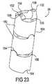
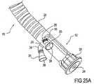
好ましい実施形態では、細長い本体の少なくとも一部分が、複数の隣接するリンクを備える。トルクは、種々のトルク伝達機構によって隣接するリンクを通じて伝達することができる。例えば、いくつかの実施形態では、複数の隣接するリンクが少なくとも第1のリンクおよび隣接する第2のリンクを含む場合、トルク伝達機構は、隣接する第2のリンク内の少なくとも1つの溝と摺動自在に係合可能な、第1のリンクから突出する少なくとも1つの突起物または歯を備え、トルク伝達機構は、リンクが回転可能な間に、本体の前記部分を通じてトルクを伝達する。いくつかの実施形態では、少なくとも1つの突起物は一対の突起物を備え、各々の突起物は、第1のリンクの外面から、他方の突起物と正反対の位置において外方に延びている。それに対応して、少なくとも1つの溝は、各々がその中に入ってくる1つまたは対の突起物を受け入れるように構成された一対の溝を備えることができる。第1のリンクが外面を有する丸く盛り上がった環を備え、隣接する第2のリンクが内面を有する第2の丸く盛り上がった環を備える場合、第1の丸く盛り上がった環の外面は長手方向の軸線に沿って第2の丸く盛り上がった環の内面と嵌め合い可能であり、各環は長手方向の軸線から遠ざかるように回転可能である。いくつかの実施形態では、各溝は、実質的に長手方向の軸線と整合させた第1の溝端部および第2の溝端部を備えており、長手方向の軸線から遠ざかるような環の回転中、溝に沿って突起物が摺動することができる。このような突起物は内面から内方に延びることができ、溝はこのような突起物を受け入れるように隣接するリンクの外面上に配置することができることが分かる。従って、突起物および関連する溝は、逆配列で同様に機能することができる。 In a preferred embodiment, at least a portion of the elongate body comprises a plurality of adjacent links. Torque can be transmitted through adjacent links by various torque transmission mechanisms. For example, in some embodiments, if the plurality of adjacent links include at least a first link and an adjacent second link, the torque transmission mechanism slides with at least one groove in the adjacent second link. With at least one protrusion or tooth projecting from the first link that is movably engageable, the torque transmitting mechanism transmits torque through the portion of the body while the link is rotatable. In some embodiments, the at least one protrusion comprises a pair of protrusions, each protrusion extending outwardly from the outer surface of the first link at a position opposite the other protrusion. Correspondingly, the at least one groove can comprise a pair of grooves each configured to receive one or a pair of protrusions entering therein. When the first link comprises a round raised ring having an outer surface and the adjacent second link comprises a second round raised ring having an inner surface, the outer surface of the first round raised ring is a longitudinal axis. Along the inner surface of the second round raised ring, each ring being rotatable away from the longitudinal axis. In some embodiments, each groove includes a first groove end and a second groove end that are substantially aligned with the longitudinal axis, during rotation of the ring away from the longitudinal axis. The protrusion can slide along the groove. It can be seen that such protrusions can extend inward from the inner surface and the grooves can be located on the outer surface of adjacent links to receive such protrusions. Thus, the protrusions and associated grooves can function in reverse as well.
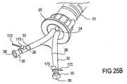
別の実施形態では、トルク伝達機構は、隣接する第2のリンク内のスロットと摺動自在に係合可能な、第1のリンクから突出する突起物またはピンを備える。これは、本体の固定が解除され所望の形状を形成することができる状態での隣接するリンクの離脱を防止することによってトルクを伝達するトルク伝達機構の一例である。いくつかの実施形態では、複数の隣接する係合可能なリンクは、隣接するリンク第1のリンクおよび隣接する第2のリンクならびに隣接する第2のリンクの少なくとも1つのスロットに摺動自在に係合可能な第1のリンクから突出する少なくとも1つのピンを備えるトルク伝達機構を備える。さらに、いくつかの実施形態では、少なくとも1つのピンが一対のピンを備えており、各ピンは、第1のリンクの外面から外方に別のピンと正反対の位置に延びている。同様に、少なくとも1つのスロットは、一対のスロットを備えており、各々のスロットが、それらを貫通する該一対のピンのうちの1つまたは対を受け入れるように構成されている。 In another embodiment, the torque transmission mechanism comprises a protrusion or pin projecting from the first link that is slidably engageable with a slot in the adjacent second link. This is an example of a torque transmission mechanism that transmits torque by preventing the detachment of adjacent links in a state where the main body is unlocked and a desired shape can be formed. In some embodiments, the plurality of adjacent engageable links are slidably engaged in at least one slot of the adjacent link first link and the adjacent second link and the adjacent second link. A torque transmission mechanism comprising at least one pin projecting from the matable first link; Further, in some embodiments, the at least one pin comprises a pair of pins, each pin extending outwardly from the outer surface of the first link to a position opposite the other pin. Similarly, the at least one slot comprises a pair of slots, each slot configured to receive one or a pair of the pair of pins extending therethrough.
好ましい実施形態では、第1のリンクは外面を有する第1の丸く盛り上がった環を備え、隣接する第2のリンクは内面を有する第2の丸く盛り上がった環を備え、第1の丸く盛り上がった環の外面は、長手方向の軸線に沿って第2の丸く盛り上がった環の内面と嵌め合い可能であり、各環は、長手方向の軸線から遠ざかるように回転可能である。一般に、各スロットは、実質的に長手方向の軸線に整合させた第1のスロット端部および第2のスロット端部を備えており、長手方向の軸線から遠ざかるような環の回転中、スロットを通ってピンが摺動することができる。このようなピンは内面から内方に延び、隣接するリンク上のスロットを通って延びることができることが分かる。従って、ピンおよび関連するスロットは、逆配列で同様に機能することができる。 In a preferred embodiment, the first link comprises a first round raised ring having an outer surface, and the adjacent second link comprises a second round raised ring having an inner surface, the first round raised ring. The outer surface of the ring can be mated with the inner surface of the second rounded ring along the longitudinal axis, and each ring is rotatable away from the longitudinal axis. In general, each slot includes a first slot end and a second slot end that are substantially aligned with the longitudinal axis so that the slot is rotated during rotation of the ring away from the longitudinal axis. The pin can slide through. It can be seen that such pins extend inward from the inner surface and can extend through slots on adjacent links. Thus, the pins and associated slots can function in reverse as well.
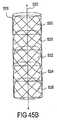
さらに別の実施形態では、トルク伝達機構は、隣接するリンクの離脱を防止するために、複数の隣接する係合可能なリンクを覆う被覆を備える。いくつかの例では、トルク伝達用被覆は、編み材料などの補強材を含むぴったりとフィットする外装を備える。補強材は、例えば、ナイロン、ポリウレタン、テフロン(登録商標)、金属、または重合体を含むことができる。任意選択的に、補強材に重合体を塗布してもよく、補強材を別個の重合体成分で覆ってもよい。代替的に、トルク伝達被覆がリンク自体の上に重合体被膜を備えてもよい。 In yet another embodiment, the torque transmission mechanism includes a covering that covers a plurality of adjacent engageable links to prevent detachment of adjacent links. In some examples, the torque transmitting coating includes a snug fit sheath that includes a reinforcement such as a knitted material. The reinforcing material can include, for example, nylon, polyurethane, Teflon, metal, or polymer. Optionally, a polymer may be applied to the reinforcement and the reinforcement may be covered with a separate polymer component. Alternatively, the torque transmission coating may comprise a polymer coating on the link itself.
さらに別の実施形態では、近位端、遠位端、および該近位端と遠位端との間に延びる少なくとも1つの管腔を有する細長い本体を備える管腔内装置を提供するが、該管腔内装置では、細長い本体の少なくとも一部分は、固定を解除されている際に互いに相対的に回転可能な第1のリンクならびに隣接する第2のリンクを少なくとも備え、少なくとも1つの管腔のうちの1つは、少なくとも1つの区画を有するリンクを通って延びる。いわば少なくとも1つの区画に接触することによってトルクを伝達するように、少なくとも1つの管腔のうちの1つを貫通する細長い軸が存在する。さらに、リンクの互いに相対的な回転を防止することによって起動と同時にリンクを固定する固定機構を提供する。 In yet another embodiment, an endoluminal device is provided comprising an elongated body having a proximal end, a distal end, and at least one lumen extending between the proximal and distal ends, In the endoluminal device, at least a portion of the elongate body comprises at least a first link that is rotatable relative to each other when unlocked, as well as an adjacent second link, of at least one lumen One of which extends through a link having at least one section. There is an elongate shaft that penetrates one of the at least one lumen so as to transmit torque by contacting at least one compartment. Furthermore, a fixing mechanism for fixing the link simultaneously with activation by preventing the links from rotating relative to each other is provided.
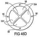
いくつかの実施形態では、少なくとも1つの区画は、内向きの突出部を備える。また、リンクを通って延びる少なくとも1つの管腔は、内向きの突出部を形成する溝付きの形状を有することができる。別の実施形態では、少なくとも1つの区画は、少なくとも1つの管腔のうちの1つを跨ぐ仕切りを備える。軸は、少なくとも1つの管腔を貫通し、各々のリンク内の区画間に位置する。複数の隣接するリンクのトルキングは、軸および区画を通じて伝達される。例えば、第1のリンクにトルクを与えることにより、第1のリンクは、軸が区画に接触するまで長手方向の軸線を中心として回転する。区画が全体として位置合わせされているので、軸は、第2のリンク内の区画にも接触することになる。その結果、トルクが第1のリンクから第2のリンクへ伝達される。この伝達を任意の数のリンクを通して繰り返し、複数の隣接するリンクを通じてトルクを伝達することができる。 In some embodiments, at least one compartment comprises an inward projection. Also, the at least one lumen extending through the link can have a grooved shape that forms an inward projection. In another embodiment, the at least one compartment comprises a partition that straddles one of the at least one lumen. The shaft passes through at least one lumen and is located between the compartments in each link. Torqueing of multiple adjacent links is transmitted through shafts and compartments. For example, by applying torque to the first link, the first link rotates about the longitudinal axis until the shaft contacts the compartment. Since the compartments are aligned as a whole, the shaft will also contact the compartments in the second link. As a result, torque is transmitted from the first link to the second link. This transmission can be repeated through any number of links to transmit torque through a plurality of adjacent links.
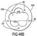
さらに別の実施形態では、トルク伝達機構は、卵形状の複数の隣接するリンクを備える。また、別の実施形態では、トルク伝達機構は、隣接するリンクを通って延びる複数のワイヤまたはロッドを備える。好ましい実施形態では、これらの複数のロッドは、約8本〜64本のロッドを含む。トルクは、これらのトルク伝達機構を通じてリンクからリンクへ伝達される。 In yet another embodiment, the torque transmission mechanism comprises a plurality of egg-shaped adjacent links. In another embodiment, the torque transmission mechanism comprises a plurality of wires or rods extending through adjacent links. In preferred embodiments, the plurality of rods comprises about 8 to 64 rods. Torque is transmitted from link to link through these torque transmission mechanisms.
さらに、近位端、遠位端、視覚化要素および固定機構を有する細長い本体を提供する工程を含むアクセス方法を提供するが、該方法では、本体は、固定が解除された状態では所望の形状を形成し、固定された状態では所望の形状を保持することができる。本方法はさらに、遠位端がターゲット部位に到達するように所望の形状を形成しながら固定を解除した状態で身体通路を通して本体を導入する工程と、固定機構を作動させて本体を所望の形状に保持する工程と、視覚化要素を用いてターゲット部位を観察する工程とを含む。 Furthermore, an access method is provided that includes providing an elongate body having a proximal end, a distal end, a visualization element and a locking mechanism, wherein the body is in a desired shape when unlocked. In a fixed state, a desired shape can be maintained. The method further includes introducing the body through the body passageway in an unlocked state while forming the desired shape so that the distal end reaches the target site, and actuating the securing mechanism to shape the body into the desired shape. And maintaining the target site using a visualization element.
本体を導入する工程は、本体が所望の形状を形成しながら固定を解除した状態で身体通路の形状を推測することを可能にする工程を含むことができる。あるいは、本体を導入する工程は、所望の形状を形成しながら固定を解除した状態で身体通路を通して本体を操向する工程を含んでもよい。いずれの状態においても、いくつかの実施形態では、固定機構を作動させる工程がリンクを互いに固定された関係に保持する工程を含むように、本体は、複数の隣接するリンクを備える。詳細には、リンクを保持する工程がリンクをくさび結合してそれらを摩擦によって保持する工程を含むように、複数の隣接するリンクは、複数の嵌め込み可能な要素を備えることもある。 The step of introducing the body can include the step of allowing the body passageway to be inferred with the body unlocked while forming the desired shape. Alternatively, the step of introducing the main body may include a step of steering the main body through the body passage in a state where the fixation is released while forming a desired shape. In any state, in some embodiments, the body comprises a plurality of adjacent links such that actuating the securing mechanism includes maintaining the links in a fixed relationship with each other. In particular, a plurality of adjacent links may comprise a plurality of pluggable elements such that the step of holding the links includes wedge coupling the links and holding them by friction.
本体が近位端と遠位端との間に延びる少なくとも1つの管腔を含む場合、本方法はさらに、該少なくとも1つの管腔を通じて器具を導入する工程を含む。いくつかの実施形態では、器具は、ツールアームを備える。細長い本体が視覚化用管腔をさらに含み、かつ視覚化要素が内視鏡を備える場合、本方法は、内視鏡を視覚化用管腔内に配置する工程をさらに含む。 If the body includes at least one lumen extending between the proximal and distal ends, the method further includes introducing an instrument through the at least one lumen. In some embodiments, the instrument comprises a tool arm. If the elongate body further includes a visualization lumen and the visualization element comprises an endoscope, the method further includes positioning the endoscope within the visualization lumen.
本発明の他の目的および利点は、添付の図面と併せて、以下の詳細な説明から明らかになるであろう。 Other objects and advantages of the present invention will become apparent from the following detailed description, taken in conjunction with the accompanying drawings.
(発明の詳細な説明)
(I. 概要)
本発明のシステム2の一実施形態を図1に示す。システム2は、近位端12および遠位先端部16で終了する遠位端14を有する細長い本体10を含む。本体10は、患者の体内の内部ターゲット部位にアクセスするために用いられる。例えば内視鏡検査においては、一般に、近位端12を身体の外側に保った状態で、遠位端14が身体開口部を通じて挿入され、1つまたはそれ以上の生来存在する体腔を通ってターゲット部位に到達する。従って、本体10は、偏向を可能にするための材料の選択またはリンク、ヒンジ、コイルもしくは他の類似する構造体が含まれるような軸20の設計により、変更可能かつ/または操向可能な軸20を有する。従って、図1は、本体が湾曲を含む偏向した状態の本体10を示す。このような偏向および/または操向は、ターゲット部位まで体腔を通過するのに役立つことができ、近位端12近傍のハンドル22の操作によって達成される。しかしながら、システム20をそのような偏向および/または操向を本体10の配置のために利用することがより少ないかもしれない腹腔鏡下手技に用いてもよいことが分かる。いずれにしても、例えば安定した視覚化プラットフォームを提供するためには、軸20の一部または全部の硬化がおそらく望ましいであろう。従って、後節において説明するように、材料の選択または固定機構が含まれるような軸20の設計によって所望の形状を維持しかつ剛性をもたらすために、本体10の軸20の部分が固定可能である。(Detailed description of the invention)
(I. Overview)
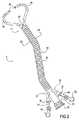
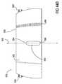
One embodiment of the
本体10は、該本体10の少なくとも遠位部分を越えてまたはそれを通って、一般に、図に示すように本体10の全長の大部分に沿って延びる少なくとも1つのアーム誘導用管腔26をも含む。ここでは、図1において、各々が近位端12近傍の軸20に沿った位置から遠位先端部16まで延びる2つのアーム誘導用管腔26を示す。さらに、本体10は、軸20を通って遠位先端部16まで延びるスコープ用管腔24を含む。 The
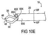
システム2は、少なくとも1本のツールアーム30をも含むが、図1では2本を示しており、それらのうちの各々のアーム30が、点線で示すように別個のアーム誘導用管腔26を通じて挿入可能である。各ツールアーム30が、近位端32、遠位端34およびそれらの間で延びる軸36を有する。遠位端34は、例えば概略的に示す隣接するリンクの操作によって操向可能である。そのような操向性は、近位端32の一部である操向用カフ35によって制御することができる。軸36は一般に可撓性または偏向可能であり、周りを取り囲む本体の軸20の偏向を可能にする。各ツールアーム30が、それらを貫通するツール配備用管腔38をさらに含む。 The
この実施形態では、システム2は、少なくとも1つのツール40をも含んでおり、図1には2つを示す。各ツール40が遠位端42、近位端44およびそれらの間に細長い軸46を含んでおり、アーム30のツール配備用管腔38を通り抜けることができる。各ツール40が、遠位端42に配置されたエンドエフェクタ48、および任意選択的に、身体の外側からのエンドエフェクタ48操作用のハンドル50を近位端44に有する。ツール40は、エンドエフェクタ48がアーム30の遠位端34から現れるように前進する。 In this embodiment, the
図2に、組み立てた構成の図1のシステム2を示す。ここでは、ツールアーム30は、本体の軸20のアーム誘導用管腔26を通じて挿入された状態で示されている。アーム30の操向可能な遠位端34は本体10の遠位端14から突出し、アーム30の近位端32は本体10の近位端12から突出している。図に示すように、操向用カフ35は、アーム30の近位端32に配置されている。さらに、エンドエフェクタ48がアーム34の操向可能な遠位端34を越えて延びるように、ツール40は、ツール配備用管腔38を通じて挿入された状態で示されている。同様に、ハンドル50を有するツール40の近位端44は、操向用カフ35から突出した状態で示されている。後節において説明するように、操向用カフ35に当たるツール40の動きにより、アーム30の遠位端34が操向されることになる。 FIG. 2 shows the
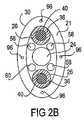
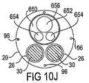
図2Aは、図2のシステム2の断面図である。この実施形態では本体10の軸20が略円筒形の外面を有するので、軸20の断面は、円形の形状を有する。円筒形の軸が楕円形、卵形または長楕円形の断面を代替的に有してもよいことが分かる。軸20は、約5mm〜約25mmの範囲、好ましくは約14mmの外径を有する。軸20は、内側中央管腔23を画定する約0.5mm〜約5mmの範囲、好ましくは約2mm〜約3mmの厚さを有する壁21を有する。壁21内に、様々な量および構成で存在することのできる本体10を操向するための、以下プルワイヤと呼ぶ種々のプッシュワイヤまたはプルワイヤがある。代替的に、プルワイヤ96は、中央管腔23内に存在してもよい。2つ示しているが、少なくとも1つのアーム誘導用管腔26が、中央管腔23を通って延びる。各アーム誘導用管腔26が、約0.5mm〜約5mmの範囲、好ましくは約4mmの内径を有する。管腔26内に配置されているのは、ツールアーム30の軸36である。また、同様に、軸36内に配置されているのは、ツール40である。図2Aは、約2mm〜約10mmの範囲、好ましくは約4mmの内径を有するスコープ用管腔24をも示す。この実施形態では、2つのアーム誘導用管腔26およびスコープ用管腔24は遠位先端部16に維持される略三角形パターンに配列されているが、スコープでツールアーム、特にエンドエフェクタを見ることのできる任意の適した配列を用いることができる。例えば、図2Bは、軸20が卵形の形状を有し、アーム誘導用管腔26およびスコープ用管腔24が全体として整列されている実施形態の断面を示す。ここでは、ツールアーム30の観察を容易にするために、スコープ用管腔24は、各アーム誘導用管腔26の間に配置されている。図2Aおよび図2Bには、様々な必要性に対して用いることのできる付加的管腔も示している。例えば、各々が約0.5mm〜約5mmの範囲、好ましくは約2mmの内径を有する灌注/吸引用管腔60、送気用管腔56および補助管腔58が存在することができる。補助管腔58は、アーム30の遠位端またはアーム30を通じて挿入されるツール40の遠位端にあるエンドエフェクタと併せて用いるための、2〜3例を挙げれば、浸軟器具、把持ツール、刃具または光源などの付加的ツールの挿入のような様々な用途に利用することができる。 FIG. 2A is a cross-sectional view of the
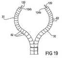
図3A〜図3Dに、ツールアーム30の操向可能な遠位端34の一連の動きを示す。遠位端34によって単独でまたは共に数多くの動きを達成することができるので、ここに示す一連の動きは、ほんの一例として役立つに過ぎない。図3Aに、本体10の遠位先端部16を示す。スコープ用管腔24が遠位先端部16で終了する2つのアーム誘導用管腔26と共に示されており、図2Aに示すような三角形パターンを形成している。図3Bは、アーム誘導用管腔26を通るツールアーム30の遠位端34の前進を示しており、これによりアーム30が遠位先端部16を越えて延びることができる。図3C〜図3Dに、好ましい構成へのアーム30の偏向を示す。図3Cに、横方向外側へのアーム30の偏向を示す。これは、操向可能な遠位端34の基部64近傍の外方への湾曲によって達成される。図3Dに、各アーム30が鉤形状を形成するような内方への湾曲によって達成される横方向内側への遠位端34の先端部分66の偏向を示す。図に示すように、アーム30の先端部分66を互いに向き合わせることにより、先端部分66は、スコープ用管腔24の経路内に正確に配置される。従って、スコープ28がスコープ用管腔24内に配置されると、ツールアーム30の先端部分66およびツールアーム30を通じて送られるあらゆるツール40をスコープ28を通じて見ることができることになる。図3C〜図3Dでは、アーム30の偏向は、所望の湾曲領域内の隣接するリンク62を用いて達成される。そのようなリンク62の実施形態および他の偏向の仕組みについては後節において論じる。さらに、図3A〜図3Dの偏向は、単一平面内において生じるように示されている。しかしながら、種々の実施形態が、複数の平面における偏向を含んでいる。同様に、図3A〜図3Dではアーム30が同時に偏向するように示されているが、アーム30は、選択的にまたは個別に偏向することができる。 3A-3D illustrate a series of movements of the steerable
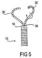
図4〜図6に、ツールアーム30のさらに可能な動きを示す。例えば、図4は、ツールアーム30の軸方向の動きを示す。矢印で示すように、例えばツール配備用管腔38内で摺動させることにより、各ツールアーム30が遠位方向または近位方向に単独で動くことができる。そのような動きは、アーム30を同一平面内に保持し、その上に、動きのさらなる多様性、従って外科的操作を可能にする。図5に、ツールアーム30の回転運動を示す。円形矢印で示すように、例えばツール配備用管腔38内でのアーム30の回転により、各ツールアーム30が単独で回転することができる。そのような回転により、アーム30は、様々な平面を通って動く。軸方向運動、側方運動および回転運動を組み合わせることにより、アーム30、従って、それらを通じて配置されるツール40は、1つまたはそれ以上の平面内の種々様々な位置を介して操作することができる。 4-6 show further possible movements of the
図6に、ツールアーム30のさらに別の関節連結を示す。いくつかの実施形態では、アーム30は、図3Dに示すように、所定の構成を形成するように偏向可能である。一般に、所定の構成を形成する場合、アーム30は、アーム30がその後さらに偏向するのを制限される所定の構成の形成に至るまで操向可能である。別の実施形態では、アームは様々な位置へ偏向可能であり、かつ所定の構成による制限を受けない。先端部分66が本体10の遠位先端部16に向かって内方にカールするようにアーム30が関節連結するそのような実施形態を図6に示す。この場合もまた、先端部分66は、スコープ用管腔24および観察用スコープ28の正面に配置される。一般に、先端部分66はスコープ28の中心軸31の向い合う両側に配置され、視野(矢印29で示す)は最大約140度の範囲にわたり、中心軸31の各側において約70度となる。さらに、視野の深さは一般に、約1cm〜約10cmの範囲となる。 FIG. 6 shows yet another articulation of the
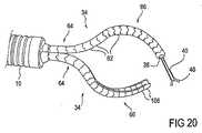
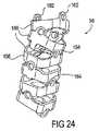
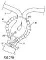
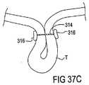
先に述べたように、本発明の管腔内ツール配備システム2は、内部組織または内部器官にアクセスし、多岐にわたる手術手技を実施するために用いることができる。図7A〜図7Bは、粘膜抜去術、または胃の粘膜および/もしくは粘膜下組織の一部の切除を行うための本システム2の一実施形態の使用法を示す。図7Aは、食道Eを通じた胃Sへの本体10の前進を示す。次いで、本体10が胃S内の所望の位置へ操向され、遠位先端部16のスコープ28を通じて胃粘膜Mが視覚化される。図7Bを参照すると、次いで、ツールアーム30が本体10を通じて送られ、関節連結される。先に述べたように、ツール40をツールアーム30を通じて送ってもよく、エンドエフェクタ48を各アーム30の遠位端に配置してもよい。ここでは、把持具80が一方のアーム30の遠位端に配置され、カッタ81が他方のアーム30の遠位端に配置されている。把持具80は、粘膜Mの一部を把持するために用いられる。次いで、粘膜Mの把持された部分をツールアーム30の回転または操作によって持ち上げることができる。図に示すように、これにより、カッタ82を用いて切断することによる粘膜Mのこの部分の安全な切除が可能となる。組織の操作および切除は、先端部分66、従って、エンドエフェクタ48と整列されたスコープ28を通じ、手技置全体を通して視覚化される。 As previously mentioned, the endoluminal
本発明のシステム、方法および装置が身体内の任意の部位、特に任意の生来の体腔または人工体腔における診断および外科的手技に応用可能であることが分かる。そのような部位は、2〜3例を挙げれば、胃腸管、尿道、腹膜腔、心血管系、呼吸器系、気管、洞腔、女性生殖器系および脊柱管内に位置する可能性がある。これらの部位へのアクセスは、任意の体腔を通じて、または固形組織を通じて達成することができる。例えば、胃には経食道到達法により、心臓には経孔アクセス法により、直腸には経直腸到達法により、子宮には経膣到達法により、脊柱には経孔アクセス法により、また腹部には経孔アクセス法によりアクセスすることができる。 It will be appreciated that the systems, methods and devices of the present invention are applicable to diagnostic and surgical procedures in any part of the body, particularly any natural or artificial body cavity. Such sites can be located in the gastrointestinal tract, urethra, peritoneal cavity, cardiovascular system, respiratory system, trachea, sinus, female genital system and spinal canal, to name a few. Access to these sites can be achieved through any body cavity or through solid tissue. For example, transgastric access for the stomach, transrectal access for the heart, transrectal access for the rectum, transvaginal access for the uterus, transforal access for the spine, and abdomen. Can be accessed by the acupuncture access method.
本発明のシステムおよび装置を用いて、様々な手技を実施することができる。以下の手技は、使用に対しての発案を意図するものであり、決してそのような用途を限定するとみなされるものではない:喉頭鏡検査、鼻鏡検査、咽頭鏡検査、気管支鏡検査、S状結腸鏡検査(S状結腸の検査、S状結腸は、下行結腸を直腸に連結する部分である;主として診断目的の検査であるが、生検手技および経肛門的顕微手術を実施して腫瘍を切除こともできる)。結腸鏡検査(ポリープおよび腫瘍の切除または生検用の結腸の検査)、および医師が食道、胃、および十二指腸(十二指腸上部)の内部を見ることができる食道胃十二指腸鏡検査(EGD)。手技は、嚥下困難、悪心、嘔吐、逆流、出血、消化障害、腹痛、または胸痛の原因を発見するのに用いることができるかもしれない。 Various procedures can be performed using the system and apparatus of the present invention. The following procedures are intended for use and are not considered to limit such applications in any way: laryngoscopy, rhinoscopy, pharyngoscopy, bronchoscopy, sigmoidal Colonoscopy (Sigmoid colon examination, the sigmoid colon is the part that connects the descending colon to the rectum; it is primarily a diagnostic test, but it performs biopsy procedures and transanal microsurgery to remove the tumor. Can be excised). Colonoscopy (polyp and tumor excision or colon examination for biopsy), and esophagogastroduodenoscopy (EGD) where the doctor can see inside the esophagus, stomach, and duodenum (upper duodenum). The procedure may be used to find the cause of dysphagia, nausea, vomiting, reflux, bleeding, dyspepsia, abdominal pain, or chest pain.
さらに、外科医が肝臓、胆嚢、総胆管、および膵臓における疾病を診断することができる内視鏡的逆行性胆道膵管造影(ERCP)を達成することができる。管結石除去を容易にするために、この工程と組み合わせて内視鏡的括約筋切開術を行うことができる。ERCPは、膵臓系および総胆管系の異常性確認のための重要な方法となることができる。他の療法には、2〜3例を挙げれば、胆嚢摘出術(疾患を有する胆嚢の摘出)、CBD診査(総胆管結石に対する)、虫垂切除術(疾患を有する虫垂の切除)、ヘルニア修復術におけるTAP法、TEPP法その他(あらゆる種類のヘルニアに対する)、胃底ひだ形成術手技およびHISS手技(胃食道逆流性疾患に対する)、十二指腸穿孔の修復、後期上部G.I.T.癌腫の待機的管理、選択的迷走神経切断術(消化性潰瘍に対する)、脾臓摘出術(罹患した脾臓の摘出)、胃拘束型治療法および吸収不良型治療法(病的肥満に対する)、上部G.I.内視鏡検査ならびに下部G.I.内視鏡検査(診断用内視鏡検査および治療的内視鏡検査)、幽門形成術(小児の先天性変形に対する)、結腸瘻造設術、結腸切除術、副腎摘出術(褐色細胞腫に対する副腎の摘出)、肝生検、胃空腸吻合術、部分的肝臓切除術、胃切除術、小腸部分切除術(梗塞または狭窄もしくは閉塞に対する)、癒着剥離術、直腸脱出症の治療、ヘラーの粘膜外筋切開術、門脈圧亢進症における脈管切除、組織壁への装置の取り付けならびに局所的薬物送達が含まれる。 In addition, endoscopic retrograde cholangiopancreatography (ERCP) can be achieved that allows the surgeon to diagnose diseases in the liver, gallbladder, common bile duct, and pancreas. In order to facilitate tube stone removal, an endoscopic sphincterotomy can be performed in combination with this step. ERCP can be an important method for confirmation of pancreatic and common bile duct abnormalities. Other therapies include cholecystectomy (exclusion of diseased gallbladder), CBD examination (for common bile duct stones), appendectomy (exclusion of diseased appendix), hernia repair TAP, TEPP, etc. (for all types of hernias), fundoplication and HISS procedures (for gastroesophageal reflux disease), duodenal perforation repair, late upper G. I. T. T. et al. Waiting management of carcinoma, selective vagus nerve amputation (for peptic ulcer), splenectomy (extraction of affected spleen), gastric restraint and malabsorption (for morbid obesity), upper G . I. Endoscopy and lower G. I. Endoscopy (diagnostic endoscopy and therapeutic endoscopy), pyloriplasty (for congenital deformities in children), colonostomy, colectomy, adrenalectomy (adrenal for pheochromocytoma Removal), liver biopsy, gastrojejunostomy, partial liver resection, gastrectomy, partial resection of small intestine (for infarction or stenosis or obstruction), adhesion detachment, treatment of rectal prolapse, Hella's extramucosal muscle Incisions, vasectomy in portal hypertension, attachment of the device to the tissue wall and local drug delivery are included.
(II.本体)
先に述べたように、本発明のシステム2は、近位端12および遠位先端部16で終了する遠位端14を有する細長い本体10を含む。本体10は、様々な組み合わせで存在する種々の特徴を有することができる。通常、これらの特徴には、2〜3例を挙げれば、偏向性、操向性、トルク性、固定性、視覚化要素、ツールアーム、および/または器具を通すための管腔、ならびに内蔵された視覚化要素、ツールアーム、ならびに/もしくは器具が含まれる。さらに、本体は、本体の全長または個々の部分を含む本体の任意の部分全体にわたってこれらの特徴のいずれをも有することができる。(II. Body)
As previously mentioned, the
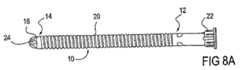
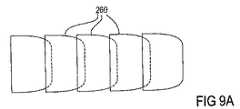
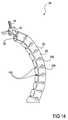
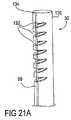
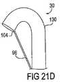
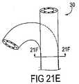
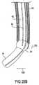
本体10の一実施形態を図8A〜図8C、図9A〜図9Dに示す。この実施形態では、本体10は、偏向性および/または操向性ならびにスコープ用管腔24などの視覚化要素、ツールアーム、および/もしくは器具を通すための管腔を含む。図8Aは、真っ直ぐな構造の本体を示す。本体10は患者の身体の内部ターゲット部位にアクセスするために用いられるので、本体10は、偏向可能かつ/または操向可能な軸20を有する。従って、図8Bは、その偏向された状態または操向された状態において種々の湾曲を有する本体10を示す。好ましい実施形態では、本体10を支持されていない解剖学的構造を通して進め、中空の体腔内の所望の部位に向けることができるように、本体10は操向可能である。いくつかの実施形態では、図8Bに示すように、本体10は、第2の部分92に対して近位側にある第1の部分90を含む。両方の部分90、92が操向可能であるが、第1の部分90は、第2の部分92がさらに関節連結されている間、所定の状態に固定することができる。これを図8Cに示しており、該図において、第1の部分90は、図8Bの状態から変化せずに固定された状態で示されており、第2の部分92は、種々の反り返った状態で示されている。反り返る際に、第2の部分92は、遠位先端部16が本体10の近位端12の方に向けられるように、横方向外側に湾曲するかまたはカールする。任意選択的に、第2の部分92も、反り返った状態または任意の他の状態で固定することができる。 One embodiment of the
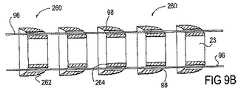
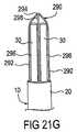
任意の適した機構によって、操向および固定を達成することができる。いくつかの実施形態では、図9Aに示すように、軸20は、多数の嵌め込み可能な要素260を備える。図9Bは、図9Aの嵌め込み可能な要素260の分解図である。この図において、1つの要素260の遠位表面262が隣接する要素の近位表面264と協働するように各要素260が配置されているのがわかる。嵌め込み可能な要素260の各々が、プルワイヤ96が貫通する1つまたはそれ以上のプルワイヤ用管腔98を含む。プルワイヤ96は、要素260を嵌め込み式に位置合わせされた状態に保持しかつ操向および固定を行うために用いられる。プルワイヤ98は、可撓性、ねじれ抵抗性およびプルワイヤ用管腔98を通るプルワイヤ96の滑らかな動きをもたらすように、超弾性の材料、例えばニッケルチタニウム合金で製造されるのが好ましい。代替的に、プルワイヤ96は、編んだステンレススチール、単一のステンレススチールワイヤ、ポリパラフェニレンテレフタルアミド(Kevlar(登録商標)のような)、高張力モノフィラメント糸、これらの組み合わせまたは任意の適した材料で製造することができる。 Steering and anchoring can be achieved by any suitable mechanism. In some embodiments, as shown in FIG. 9A, the
通常、プルワイヤ96が弛緩しているときに表面262、264が互いに相対的に回転することができるように、隣接する表面262、264は、嵌まり合うように輪郭形成されている。これにより、軸20は、その全長にわたっていずれの方向にも湾曲を形成することができる。各プルワイヤ96は、その遠位端が軸20に沿った特定の要素260または遠位先端部16に固定されている。特定のプルワイヤ96に張力が印加されると、固定点に対して近位側の軸20に湾曲が生じ、その結果軸20が操向される。様々な方向への操向を達成するために、プルワイヤ96は、種々のパターンで配列することができる。例えば、図9Cは、図8Bの第1の部分90における軸20の断面図である。ここでは、8本のプルワイヤ96(4本のプルワイヤ96aおよび4本のプルワイヤ96b)が壁21を貫通しているのが示されている。4本のプルワイヤ96aは第1の部分90の遠位端で終了し、第1の部分90を操向するのに用いられる。プルワイヤ96aは等距離に配置されているので、別個にまたは組み合わせてプルワイヤ96aに張力を印加することにより、第1の部分90は、任意の所望の方向に操向される。第1の部分90は、任意の適した機構を用いてプルワイヤ96aの張力を保持することにより、所定の位置に固定することができる。例えば、張力は、要素260が圧迫されてそれらが張力を保持している摩擦によって固定された状態になるまでプルワイヤ96に対して同時に印加することができる。 Typically,
図9Dは、図8Bの第2の部分92における軸20の断面図である。ここでは、4本のプルワイヤ96bが壁21を貫通しているのが示されている。これらのプルワイヤ96bは、図9Cに示すように、第1の部分90を通って延び、遠位先端部16近傍で終了する。プルワイヤ96bは等距離に配置されているので、別個にまたは組み合わせてプルワイヤ96bに張力を印加することにより、第2の部分92は、任意の所望の方向に操向される。プルワイヤ96bは第1の部分90も通過しているので、第1の部分が固定されていない場合には、そのような操向によって第1の部分90にも湾曲が生じるかもしれない。しかしながら、そのような影響はわずかなものであり、第1の部分90において操向することによって是正するかまたは補正することができ、かつ固定によって回避することができる。第2の部分92も、任意の適した機構を用いてプルワイヤ96bの張力を保持することにより、所定の位置に固定することができる。 FIG. 9D is a cross-sectional view of the
この実施形態では、壁21は、近位端12から遠位端14まで途切れることなく延びており、第1の部分および第2の部分90、92は、それらを通って延びるプルワイヤ96の終端点によって決定される。代替的に、第1の部分および第2の部分90、92は、互いに隣接して同軸上に配置された別個の軸で構成されていてもよい。 In this embodiment, the
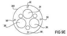
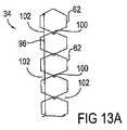
図9Bに示す実施形態では、嵌め込み可能な要素260は、本体10の全長を貫通する中央管腔23を有する。図9C〜図9Dに示すように、器具またはツールをこの管腔23を通じて送ってもよく、管腔23内に管が存在し、それらを通じて器具もしくはツールを送ってもよい。好ましい実施形態では、嵌め込み可能な要素260は、それレアの中に形成された穴を有しており、これにより、要素260が積み重ねられると、各穴の位置合わせによって管腔が形成される。例えば、図9Eは、中に形成された穴を示す嵌め込み可能な要素260の断面図であり、該穴が、管腔として機能する。図に示すように、スコープ用管腔24、アーム誘導用管腔26、および補助管腔58は、プルワイヤ用管腔98が周縁沿いに配置された状態で要素260の中心を通って延びる。 In the embodiment shown in FIG. 9B, the
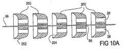
プルワイヤ用管腔98も、要素260の中心を通って延びることができることが分かる。例えば、図10Aは、積み重ねられた嵌め込み可能な要素260の中心を通って延びるプルワイヤ96を有する実施形態を示している。図10Aは、嵌め込み可能な要素260の分解図であり、該図において、要素260は、1つの要素260の遠位表面262が隣接する要素の近位表面264と協働するように配置されている。図に示すように、嵌め込み可能な要素260の各々が、その中心を通るプルワイヤ用管腔98を含む。図10Bは、図10Aの嵌め込み可能な要素260の断面図である。図に示すように、嵌め込み可能な要素260は、固定用プルワイヤ用の管腔98cを含み、スコープ用管腔24、アーム誘導用管腔26、補助管腔58および操向用に用いられる種々のプルワイヤ用管腔98などの他の様々な管腔に取り囲まれた要素260の中心部に、該固定用プルワイヤ用の管腔98cを通るプルワイヤ96cを有する。ひとたび要素260が所望の配列に配置されれば、軸20は、中央プルワイヤ96cによって所定の位置に固定することができる。プルワイヤ96に張力を印加することによって要素260が圧迫され、張力を保持している摩擦によってそれらが固定される状態となる。 It can be seen that the
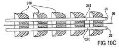
さらに、ライナ266が、積み重ねられた嵌め込み可能な要素260の任意の管腔を貫通することができる。そのようなライナ266の形状が、嵌め込み可能な要素260の管腔穴を連結する切れ目なく続く管腔を生成する。図10Cは、例えばアーム誘導用管腔26を貫通するライナ266を含んだ図10Aの嵌め込み可能な要素260を示す。同様に、図10Dは、図10Cの嵌め込み可能な要素260の断面図を示す。ここでは、ライナ266は、嵌め込み可能な要素260を通して配置された状態で示されており、嵌め込み可能な要素260は、それらを通る管腔24、26、58を形成している。ライナ266がプルワイヤ用管腔98も通って延びることができることも分かる。ライナ266は、摩擦を低減するために管腔表面上に親水性の被覆剤を塗布してもよく、あるいはライナ266がTeflon(登録商標)、フルオロエチレンポリマー(FEP)またはその類似物のような潤滑性ポリマーで構成されていてもよい。 Further, the
先に述べたように、本体10の軸20は偏向性、操向性、トルク性、固定性、視覚化および種々のツール等を有する特徴を提供するために、様々な構造を有することができるのが分かる。偏向性、操向性および/または固定性を提供する構造の例示的な実施形態は上に説明されており、すべて2002年6月13日に提出されかつあらゆる目的に対して引用により本明細書に組み込まれる、米国特許出願第10/173、203号、第10/173、227号、第10/173、238号、第10/173、220号の一部継続出願である2002年10月25日に提出された同時係属の米国特許第出願第10/281、462号に提供している。これも関心のあるものでありかつあらゆる目的に対して引用により組み込まれるのは、各々が2002年10月25日に提出された同時係属の米国特許第出願第10/281、461号および第10/281、426号である。固定性には所望の形状に本体を固定しその長さに沿った1つまたはそれ以上の湾曲を維持する機能が含まれることが理解される。従って、これらの例では、本体は、形状固定可能である。トルク性を提供する構造については後節において説明するが、これらの特徴は本明細書に説明するいずれの実施形態にも適用可能であることが理解される。 As previously mentioned, the
さらに、本体10は従来の内視鏡または腹腔鏡で構成されていてもよいことが分かる。従来の内視鏡の例示的な実施形態は、あらゆる目的に対して引用により本明細書に組み込まれる米国特許第3、948、251号、第4、036、218号、第4、201、198号、第4、224、929号、第4、998、171号、第5、020、539号、第5、035、231号、第、5、068、719号、第5、170、775号、第5、172、225号、第5、187、572号、および第5、196、928号に提供している。図10Eは、視覚化要素652および少なくとも1つの光源654を含む従来の内視鏡650または他の内視鏡からなる本体10の軸20を示す。この実施形態では、内視鏡650は、ツールアーム30を通すための2つのアーム誘導用管腔26を含む。ツールアーム30が各々図に示すようなエンドエフェクタ48を有するか、またはエンドエフェクタ48を有するツール40を各アーム30内のツール配備用管腔38を通じて送ってもよい。図10Fは、図10Eの軸20の断面図である。図10Gは、複数の操向可能および/または固定可能な嵌め込み可能要素260を備える本体10の軸20を示しており、視覚化要素652および少なくとも1つの光源654を含む従来の内視鏡650または他の内視鏡が該軸20を貫通している。内視鏡650は、本体10の軸20内の内視鏡用管腔656を通じて前進可能かつ/または格納可能であってもよく、軸20内に固定してもよい。内視鏡650は、内視鏡650の遠位端658が軸20の遠位先端部16とぴったり重なるように配置してもよく、図に示すように、遠位先端部16を越えて延びた位置を含めた軸20に沿った任意の位置に配置してもよい。図10Hは、図10Gの断面図である。この図では、軸20の壁21が操向および/または固定用のプルワイヤ96を含んでいるのがより明瞭に見える。さらに、本体10の軸20は、図10Iに示すように、ツールアーム30を通すための1つまたはそれ以上のアーム誘導用管腔26を含むことができる。ツールアーム30が各々図に示すようなエンドエフェクタ48を有するか、またはエンドエフェクタ48を有するツール40を各アーム30内のツール配備用管腔38を通じて送ってもよい。図10Jは、図10Iの断面図である。 Furthermore, it can be seen that the
図10Kは、一体型または内蔵型の視覚化要素652および少なくとも1つの光源654を有する本体10の軸20を示す。この場合もまた、軸20は、操向および/または固定用の複数の嵌め込み可能な要素260を備える。任意選択的に、軸20は、図10M〜図10Nに示す管腔660を含むこともでき、該管腔660を通じて、ツールアーム30を含む種々のツール、器具または装置を送ることができる。あるいは、図10Oに示すように、一体型の視覚化要素および少なくとも1つの光源654を有する軸20が、ツールアーム30を通すための別個のアーム誘導用管腔26を有してもよい。図10Oのツールアーム30は代替的に軸20に固定するかまたはそれと一体であってもよいことも分かる。 FIG. 10K shows the
どの実施形態の視覚化要素652も、視覚映像を伝送および/または検出する要素を含む。例えば、そのような視覚化要素652は、コヒーレントなファイバの束、超音波装置、および/または電磁放射線の可視スペクトル、電磁放射線の赤外線スペクトル、電磁放射線の紫外線スペクトルならびに/もしくは電磁放射線のX線スペクトルにおいて動作するための電荷結合素子(CCD)を含むことができる。 The
(III.ツールアーム)
先に述べたように、システム2は、少なくとも1つのツールアーム30も含んでおり、各々アーム30が、本体10内の別個のアーム誘導用管腔26を通じて挿入可能である。図11に示すように、各ツールアーム30が、近位端32、遠位端34およびそれらの間に軸36を有する。概略的に示すように、遠位端34は、例えば隣接するリンク62の操作によって操向可能である。そのような操向性は、近位端32内に配置された操向用カフ35によって随意に制御することができる。各ツールアーム30が、それを通るツール配備用管腔38をさらに含む。(III. Tool arm)
As previously mentioned, the
(A.遠位端)
図12A〜図12Bは、アーム30の操向性を可能にするために遠位端34に配置された隣接するリンク62の実施形態を示す。ここでは、リンク62は、ヒンジ構造100によって枢着されている。図12Aに示すように、リンク62は、ヒンジ構造100による連結によって該ヒンジ構造100の真向かいのリンク62間に隙間102が生じるような形状を有する。プルワイヤ96がリンク62を通って延び、固定点104で終了しているのが示されている。ここで図12Bを参照すると、プルワイヤ96の収縮によってリンク62が共に引き寄せられ、リンク62間の隙間102を最小化する。図に示すように、リンク62の形状および配列により、この動きがアーム30に湾曲を生じさせる。遠位端34は、実質的にまっすぐな状態から隙間102が完全に塞がる最大湾曲の間で任意の湾曲を有するように操向してもよく、別の制限機能を設けてもよい。いくつかの実施形態では、最大360度の遠位端34の曲率が可能である。遠位端34は、プルワイヤ96の前進、または反動力で遠位端34をまっすぐにすることになるバネの存在によってまっすぐな状態に戻ることができる。(A. Distal end)
12A-12B show an embodiment of an
図13A〜図13Bは、アーム30の操向性を可能にするために遠位端34に配置された隣接するリンク62の類似の実施形態を示す。ここでもまた、リンク62は、ヒンジ構造100によって枢着されている。しかしながら、図13Aに示すように、リンク62は、ヒンジ構造100による連結によってヒンジ構造100の両側のリンク62間に隙間102が生じるような形状を有する。プルワイヤ96がリンク62を通って延び、固定点104で終了しているのが示されている。ここで図13Bを参照すると、プルワイヤ96の収縮によってリンク62が共に引き寄せられ、プルワイヤ96に沿ったリンク62間の隙間102を最小化し、かつヒンジ構造100の反対側の隙間102を最大化している。図に示すように、リンク62のこの形状および配列により、この動きがアーム30に湾曲を生じさせる。遠位端34は、プルワイヤ96の前進によって、または反動力で遠位端34をまっすぐにすることになるバネの存在によって、まっすぐな状態に戻ることもできる。しかしながら、この実施形態では、遠位端34は、プルワイヤ96の連続的前進によって反対方向に偏向または湾曲することができる。プルワイヤ96の前進によってヒンジ構造100の反対側の隙間102が最小化され、反対方向に湾曲を生じさせる。同様に、バネを備えて、この反対方向への湾曲から遠位端34をまっすぐにすることができる。 FIGS. 13A-13B show a similar embodiment of an
図14に、図13A〜図13Bに示す実施形態に類似した実施形態を示す。リンク62がヒンジ構造100によって枢着されているのが示されている。ここでは、ヒンジ構造100は、偏向を単一の平面に制限するために並列に配列された枢動ピン106を示す。いくつかの実施形態では、ヒンジ構造は、遠位部分の偏向を単一平面内に制限するために並列に配置された、軸を形成するオス座面およびメス座面を備える。リンク62は、枢動ピン106による連結によってリンク62間に隙間102が生じるような形状を有する。枢動ピン106の片側の隙間102が塞がる同時に、ピン106の反対側の隙間が開く。図14は、アーム30のツール配備用管腔38を通って前進したツール40のエンドエフェクタ48をも示している。 FIG. 14 shows an embodiment similar to the embodiment shown in FIGS. 13A-13B. The
図15に、ツールアーム30の可能な偏向または動きの例を示す。ここでは、2本のアーム30が細長い本体10の遠位先端部16から現れているのが示されている。各アーム30の遠位端34は、操向可能でかつ複数の隣接するリンク62からなる。左側のアーム30は、先端部分66が内側にカールしてほぼ完全な円形を形成する位置へ操向された状態示されている。これと対照的に、右側のアーム30は、先端部分66がわずかに内側に偏向して弧状を形成する位置へ操向された状態で示されている。このようにして、アーム30は、湾曲の度合いを変えるために別個に操向可能とすることができる。アーム30は、協働させて手術手技を実行しかつ中心に位置するスコープを通じた視認性を維持するために、内向きに操向可能であるのが好ましい。 FIG. 15 shows an example of possible deflection or movement of the
図16A〜図16Bに、複数の隣接するリンク62を備えるツールアーム30の別の実施形態を示す。ここでは、リンク62は円盤110からなっており、円盤110は、円盤110が積み重ねられたときに円盤110間に隙間102が形成されるように傾斜させた面を有する。円盤110は、1つまたはそれ以上のワイヤまたはリボン112で連結されている。この実施形態では、図16Bに示すように、2つのリボン112があり、それぞれが、傾斜させた面がリボン112間で整列するように、積み重ねた円盤110の各々の壁内の正反対の位置に配置されている。リボン112は、壁に埋め込んでも、積み重ねた円盤と共成形しても、壁内の管腔を通じて単に送ってもよい。リボン112は円盤110の相対位置を維持し、かつ操向可能な遠位端34を、1つのみの平面内に偏向可能となるように固定する。これも図16Bに示すように、リボン112間に管腔114があり、それを通るプルワイヤ96を位置決めする。プルワイヤ96への張力の印加によって円盤110の傾斜させた面が互いに近づき、それらの間にある隙間102を塞ぐように、プルワイヤ96は、円盤110の傾斜した部分を貫通している。これによって正反対の位置にある隙間102が次々に広がり、積み重なりに湾曲を生じさせる。 FIGS. 16A-16B illustrate another embodiment of a
先に述べたように、いくつかの実施形態では、アーム30は、図3Dにおいて先に示したように、所定の構成を形成するように偏向可能である。一般に、所定の構成を形成する場合、アーム30は、アーム30がその後さらに偏向するのを抑制される所定の構成を形成するまで操向可能である。図17に、アーム30が所定の構成まで操向可能な、複数の隣接するリンク62を備えるそのようなアーム30の実施形態を示す。図に示すように、遠位端34は、遠位端34を外側へ偏向させる基部64と内側へ偏向させる先端部分66とを備える。基部64と先端部分66との間に、剛体のスペーサ68がある。スペーサ68は、より大きい細長いリンクまたは単にまっすぐな部分とみなすことができる。このようなスペーサ68の使用は任意選択的であり、特定の所定の構成を作り出すのに用いることができる。図17Aは、リンク62の形状を示す先端部分66の拡大図であり、リンク62は、リンク62内に形成されたヒンジ構造100によって枢着されている。隙間102は、遠位端34の湾曲を可能にするために、構造100の反対側に存在する。隙間102が塞がることによって特定の湾曲が形成されるようにリンク64の大きさおよび形状を変えるため、隙間102の大きさは変わることになる。これは、図17B〜図17Cにおいて最も容易に見られる。図17Bは、様々な大きさの隙間102を作り出すために様々な形状を有する基部64のリンク62を示している。図に示すように、プルワイヤ96が、隙間102に沿ってリンク62を通って延びている。プルワイヤ96に張力を印加することによってリンク62が互いに近づいて隙間102を塞ぎ、図17Cに示すような所定の湾曲が形成される。 As previously noted, in some embodiments, the
図17の所定の構成は、反対方向への湾曲を含んでおり、基部64は横方向外側へ湾曲し、先端部分66は横方向内側へ湾曲している。これらの別個の湾曲は、別々のプルワイヤ96によって達成することができる。例えば、図18Aに示すように、第1のプルワイヤ97aは、ツールアーム30の片側に沿って配置し、遠位端34に沿って中ほどに位置する固定点104aで終了させることができる。この固定点104aの近位側に位置するリンク62が、基部64を形成する。第2のプルワイヤ97bは、アーム30の反対側に沿って配置し、遠位端34の先端に位置する固定点104bで終了させることができる。通常、固定点104aと固定点104bとの間に位置するリンク62が、先端部分66を形成する。ここで図18Bを参照すると、第1のプルワイヤ97aに張力を印加することによって基部が横方向外側へ湾曲し、第2のプルワイヤ97bに張力を印加することによって先端部分が横方向内側へ湾曲する。 The predetermined configuration of FIG. 17 includes curvature in the opposite direction, with the base 64 curved laterally outward and the
図19に、所定の構成に操向された2本のツールアーム30を示す。このような操向は、図18A〜図18Bに示すプルワイヤ96を用いて達成される。固定点104aはアーム30内に隠れているが、固定点104bは目に見える。図に示すように、プルワイヤ96に張力が印加された時に、リンク62の大きさおよび形状が変化し、この構成を形成する。例えば、リンク62は全体として、基部64を通して全体としてより大きく、先端部分66を通してより小さい。さらに、この実施形態は、安定性をもたらすために、アーム30を貫通するスタビライザ120を含む。 FIG. 19 shows two
いくつかの実施形態では、操向可能な遠位端34は、所定の構成へ操向可能なリンクと拘束されることなく操向可能なリンクとの両方の種類リンクを含む。例えば、図20に、横方向外側に偏向して所定の構成を形成するような適切な形状および大きさを有するリンク62で基部64が構成された実施形態を示す。そのような偏向は、見えない位置に隠れており遠位端34に沿った中ほどの位置で終了する1本のプルワイヤを用いて達成することができる。この実施形態では、先端部分66は、拘束されずに横方向内側に偏向するような適切な大きさおよび形状を有するリンク62からなっている。先端部分66のリンク62は、拘束を受けない動き全体を支持する枢動ピン106でヒンジ式に連結されている。さらに、エンドエフェクタ48を有するツール40がアーム30内のツール配備用管腔38を通り抜けているのが示されている。これも図20に示すように、アーム30が回転され、異なる平面に位置しており、これは、前節で説明した特徴である。 In some embodiments, the steerable
リンクを含む実施形態は任意の数のリンクを有することができるのが分かる。例えば、操向可能な遠位端34は、ヒンジ構造100によってヒンジ式に連結された2つのリンク62を有することができる。この例では、軸36が第1のリンク62を第1の方向に向け、ヒンジ構造100が遠位先端部16を第2の方向に向けることになろう。さらにリンク機構62を追加すれば、より滑らかな湾曲が創り出され、かつ/または操向可能な遠位端34全体にわたって複数の湾曲が可能となるであろう。 It will be appreciated that embodiments including links can have any number of links. For example, the steerable
ツールアーム30の前述の実施形態は複数の隣接するリンクからなっていたが、アーム30は任意の適した形態の材料からなることができるのが分かる。例えば、各アーム30は、所望の湾曲を形成するために、例えばヒートセットによって形作られたポリマー管からなっていてもよい。ポリマー管は、アーム誘導用管腔26を通じた送達のために湾曲を伸ばすことを可能にするのに十分な可撓性を有しかつ管腔30から出ると所望の湾曲を形成するためのアーム30の反動を許容する材料からなる。 Although the previous embodiment of the
別の実施形態では、各アーム30は、図21A〜図21Bに示すようなスロットを有する管からなる。図21Aを参照すると、管130は、その長さに沿って一連のスロット132を有する。この実施形態では、スロット132は管130の片側に沿って存在するが、スロット132は管の両側かまたは偏向することが所望される管の任意の部分に沿って存在することができるのが分かる。図21Aに戻ってこれを参照すると、プルワイヤ96は、スロット132に沿って管内に配置されており、固定点104で管130に固定されている。プルワイヤ96に張力を印加することによって、管130が図21Bに示すようにプルワイヤ96の方に偏向する。スロット132の存在により、管130による座屈または障害を最小限に抑えて偏向および湾曲はするが管130が比較的剛体のもしくは厚みのある材料からなることが可能となる。図21A〜図21Bの管130は代替的にそれ自体が座屈または障害を最小限に抑えて偏向および湾曲することを可能にするより薄いもしくはより可撓性の材料からなるスロットを有しない中実の壁であってもよいことが分かる。さらに、種々のツールアーム30を示す以下の実施形態の各々は、中実の管またはスロットを有する管、もしくは任意の他の適した管構成からなることができる。 In another embodiment, each
図21C〜図21Dに、プルワイヤ96が管130の外側に配置され、固定点104で管130に固定されている管130からなるアーム30の実施形態を示す。図21Dに示すように、プルワイヤ96に張力を印加することによって、管130は、プルワイヤ96に向かって偏向される。プルワイヤ96が管130の外側に配置されているので、プルワイヤ96が固定点104に対するつなぎ綱となり、管130の表面に沿って追従することはない。 21C-21D show an embodiment of an
図21E〜図21Fに、ニチノールワイヤなどの形状記憶材料と共成形されたポリマー壁からなるアーム30の実施形態を示す。図21Eには、アーム30がアーム誘導用管腔26を貫通するまっすぐな状態のアーム30、およびアーム30が形状が記憶された湾曲へはね返る湾曲した状態のアーム30を示す。図21Fには、アーム30の壁内に分配された形状記憶材料280を示す図21Eのアーム30の断面図を示す。 21E-21F show an embodiment of an
図21G〜図21Hに、ツールアーム30を操向するための代替的機構を示す。図21Gを参照すると、本体10の軸20が示されており、一対のツールアーム30が該軸20から延びている。アーム30を取り囲んで、展開用フレーム290が位置する。フレーム290は、アーム30に力を印加するのに十分な強度を提供するステンレススチールなどの半剛体または剛体の材料からなる。フレーム290は、各々が軸20の遠位先端部16から延びて先端294で結合する少なくとも2つの支持体292を備える。各支持体292は、付着点296でツールアーム30に付着している。フレーム290は、遠位先端部16から先端294まで延びる作動用支持体298をも含む。図21Gに示すように、アーム30および支持体292、298は、まっすぐな形状で本体10の遠位先端部16から本体の所望の位置まで前進する。図21Hを参照すると、作動用支持体298への張力の印加によって先端294が遠位先端部16に向けて引き寄せられて支持体292を外側へ弓なりに曲げるかまたは屈曲させ、付着しているアーム30を外側へ引っ張る。同様に、支持体292はヒンジを含むことができ、支持体292は、ヒンジの部分で曲がることになろう。図21Hには付着点296で屈曲するアーム30を示しているが、アーム30はどの位置においても屈曲することができるのが分かる。このような屈曲によってツール配備用管腔38を互いの方に向け、それらを通過したツール40の協働を促進する。近位および遠位への先端294の動きによってアーム30の湾曲が変化し、操向性をもたらす。フレーム290は、周囲の組織がアーム30およびツール40に侵入しないようにしながら、作業スペースを作り出すのにも役立つ。 An alternative mechanism for steering the
ほとんどの実施形態において、偏向した状態を維持するために、ツールアームの遠位端は固定可能である。そのような固定は、任意の適した機構によって達成することができる。ツールアームがプルワイヤまたはプッシュワイヤの操作によって操向可能である場合、ワイヤを所定の位置に保持し、遠位端を所望の状態に固定することができる。多数の嵌め込み可能な要素からなりそれらをプルワイヤが通過している場合、プルワイヤは一般に、各要素を嵌まり込んで位置合わせした状態に保持しかつ操向および固定を行うために用いられる。各プルワイヤに同時に張力を印加することにより、各要素は、張力が保持されている摩擦によってそれらが固定される状態にまで圧迫することができる。別の固定機構も用いることができる。さらに、ツールアームは、本体に対するツールアームの配置を維持するために、本体内で回転させて固定することも、軸方向に固定することもできる。 In most embodiments, the distal end of the tool arm can be fixed to maintain the deflected state. Such fixation can be achieved by any suitable mechanism. If the tool arm is steerable by manipulation of a pull wire or push wire, the wire can be held in place and the distal end fixed in the desired state. When a pull wire consists of a large number of pluggable elements passing through them, the pull wire is generally used to hold each element plugged and aligned and to steer and fix. By simultaneously applying tension to each pull wire, the elements can be squeezed to a state where they are fixed by friction where the tension is maintained. Other securing mechanisms can also be used. Furthermore, the tool arm can be rotated and fixed in the main body or can be fixed in the axial direction in order to maintain the position of the tool arm relative to the main body.
(B.軸)
先に述べたように、ツールアーム30の軸36は、本体10を貫通する。本体10が偏向可能な実施形態では、軸36も偏向可能である。しかしながら、軸36は横方向に偏向可能であるのが望ましいが、軸36が軸方向の剛性を維持することも望ましい。ブレード補強したトルクを与えることが可能な管を含む、任意の適した構成を用いることができる。さらに別の実施形態を以下に説明する。(B. axis)
As described above, the
図22A〜図22Bに、コイル140を示す軸36の実施形態を示す。ここでは、図22Aに示すように、コイル140の巻きが互いに隣接して位置しており、軸方向の動きを防止しかつ軸方向の剛性を維持している。しかしながら、コイルの構成により、図22Bに示すような軸36の偏向が可能となっている。 22A-22B show an embodiment of the
別の実施形態では、図23に示すように、軸36は、複数の隣接するリンク装置150を備える。ここでは、各リンク装置150が、その面上に一対の突出する構造体152を、その基部上に一対の切欠き154を含む。1つのリンク装置150の突出する構造体152が隣接して積み重ねられたリンク装置150の切欠き154と回転可能に嵌まり合うように、突出する構造体152および切欠き154は、両方とも円弧の形状を有する。図23に示すように対の突出する構造体152および切欠き154の位置を交互に入れ替えることにより、軸36は、軸方向剛性およびねじり剛性を維持しながら両側方への曲げにおいては柔軟となる。これも図に示すのは、突出する構造体152および軸36の壁を貫通する広がった管腔158である。広がりを有することにより、突出する構造体152を越えてリンク装置150が回転する際に、該広がりに通されたロッドまたはワイヤが管腔158内で動くことが可能となる。図に示すように、丸いプルワイヤ用管腔156が、切欠き154および軸36の壁を貫通している。ロッドまたはワイヤは、リンク装置150を積み重ねられた構成に保持し、随意に、軸36を操向するのに用いてもよい。 In another embodiment, as shown in FIG. 23, the
別の実施形態では、図24に示すように、軸36は、これらも軸方向剛性を維持しながら横方向に偏向するように積み重ねられた複数の隣接するリンク装置160を備える。ここでは、各リンク装置160は、その面上に一対の突出する構造体162を、その基部上に一対の切欠き164を含む。1つのリンク装置160の突出する構造体162が隣接して積み重ねられたリンク装置160の切欠き164と回転可能に嵌まり合うように、突出する構造体162および切欠き164は、両方とも円弧の形状を有する。図24に示すように対の突出する構造体162および切欠き164の位置を交互に入れ替えることにより、軸36は、軸方向剛性およびねじり剛性を維持しながら両側方への曲げにおいては柔軟となる。この実施形態では、リンク装置150は、ロッドまたはワイヤが通過する中央管腔166を含む。ロッドまたはワイヤは、リンク装置60を積み重ねられた構成に保持するために用いられる。 In another embodiment, as shown in FIG. 24, the
(C.近位端)
ツールアーム30の近位端32は、単に末端部またはコネクタで終了することができ、そのツール配備用管腔38を通じてツール40が通される。しかしながら、近位端32は、ツールアーム30を操向するための、特にその遠位端34を操向するための操向用カフ35を任意選択的に含むことができる。(C. proximal end)
The
図25Aに、2本のツールアーム30が存在し、各々がアーム誘導用管腔26を通じて本体10の軸20内に挿入される、本体10の近位端12の実施形態を示す。図に示すように、各ツールアーム30が操向用カフ35を含んでおり、該操向用カフ35が本体10の外側に残り、ツール配備用管腔38には操向用カフ35を通じてアクセス可能である。図25Bに、2本のツールアーム30が存在し、各々が本体10のハンドル22を介してアーム誘導用管腔26を通じて挿入される、近位端12の代替的実施形態を示す。ここでもまた、各ツールアーム30が操向用カフ35を含んでおり、該操向用カフ35が本体10の外側に残り、ツール配備用管腔38には操向用カフ35を通じてアクセス可能である。この実施形態は、各アーム30上に固定機構170をも含む。固定機構170は、例えば図25Bに示すレバーを回転させることによって操作することができ、遠位端34またはツールアーム30を操向された状態もしくは偏向された状態に固定することができる。 FIG. 25A shows an embodiment of the
図26に、ツール40を通過させるツールアーム30の近位端32に配置された操向用カフ35の実施形態を示す。この実施形態では、ツールアーム30は、軸20の外周を取り囲んで等距離に配置された4本のプルワイヤ96を含む(図26では3本が見える)。先に述べたように、プルワイヤ96は、アーム30の遠位端34を操向するために用いられる。図に示すように、ツール40は、アーム30の遠位端34から現れるエンドエフェクタ48を備える遠位端42を有する。同様に、ツール40は、操向用カフ35から現れる近位端44を有する。この実施形態では、操向用カフ35は、1つの端部が少なくともプルワイヤ96に取り付けられ、一般的にアーム30自体にさらに取り付けられたじょうごの形態を有している。円弧状矢印180で示すツール40の近位端44の偏向によって近位端44が操向用カフ35に押し当たり、破線で示すように、操向用カフ35を偏向した位置まで回転させる。矢印182で示すように、そのような回転によって、偏向した位置の反対側のプルワイヤ96に張力が印加される。そのような張力によって、アーム30の遠位端34が操向される。従って、操向用カフ35内のツール40の操作は、アーム30の遠位端34を操向するために用いることができる。 FIG. 26 shows an embodiment of a
図27A〜図27Bに、操向用カフ35の別の実施形態を示す。ここでは、操向用カフ35は、球状の形態を有しており、ツールアーム30の近位端32に配置されている。図に示すように、ツール40は、ツールの遠位端42がアーム30の遠位端34から現れ、近位端44がカフ35の外側に残るように、球状カフ35内の管腔184を通過する。この実施形態では、ツールアーム30は、軸36の外周を取り囲んで等距離に配置された4本のプルワイヤ96(3本が見える)を含む。先に述べたように、プルワイヤ96は、アーム30の遠位端34を操向するために用いられる。図27Aに、アーム30の軸36から現れ球状カフ35の表面に取り付けられたプルワイヤ96を示す。同様に、図27Bに類似した図を示すが、この場合には、軸36内の管腔を通って延びるプルワイヤ96およびツール配備用管腔38を通って延びるツール40を見せるために、アーム30が切り取られている。図28Aに、まっすぐな状態の実施形態を示す。図28Bに示すように、円弧状矢印180で示すツール40の近位端44の偏向によって近位端44が操向用カフ35に押し当たり、操向用カフ35を偏向した位置まで回転させる。矢印182で示すように、そのような回転によって、偏向した位置の反対側のプルワイヤ96に張力が印加される。そのような張力によって、アーム30の遠位端34が操向される。従って、操向用カフ35内のツール40の操作は、アーム30の遠位端34を操向するために用いることができる。 27A to 27B show another embodiment of the
図26および図27A〜図27B、図28A〜図28Bに描いた操向用カフ35の実施形態は任意の所望のレベルの操向性に対して任意の数のプルワイヤ96を含むことができるのが分かる。例えば、各実施形態において、2本のプルワイヤ96は、アーム30の操向可能な遠位端34を単一平面内で動かすために、操向用カフ35の対向する両側に配置されて存在することができる。これは、側方に安定化されたアーム30用の例となろう。 The embodiment of the
(IV.ツール)
先に述べたように、システム2は、少なくとも1つのツール40も含む。いくつかの実施形態では、ツール40は、単にツールアーム30の遠位端に配置されたエンドエフェクタ48を備えるのみで、エンドエフェクタ48は、アーム30を通って延びる機構の操作によって動かされる。別の実施形態では、各ツール40が遠位端42、近位端44およびそれらの間に細長い軸46を含んでおり、アーム30のツール配備用管腔38を通り抜けることができる。軸46は一般に、ブレードまたはコイルで補強した押し出し成形品などの任意の適した材料からなるトルク安定性の管であるのが望ましい。これらの実施形態では、各ツール40が、遠位端42に位置されたエンドエフェクタ48、および任意選択的に、本体の外側からのエンドエフェクタ48操作用のハンドル50を近位端44に有する。従って、ツール40は、エンドエフェクタ48がアーム30の遠位端から出現するように前進する。(IV. Tool)
As previously mentioned, the
所望される手技または組織の操作に応じて、種々様々なエンドエフェクタ48を用いることができる。例えば、エンドエフェクタ48は、限定するものではないが、ナイフ、針、縫合糸、ホッチキス、留め具、クリッパ、電気外科用または止血用のカッタおよび凝固剤、レーザー溶接機、凍結外科手術用器具、二次スコープ、鉗子、レーザフック、トング、把持器具、開創器、プローブ、クランプ、鋏、組織近置装置、吸引器を含むことができる。 A wide variety of
図29に、鋏200の形状のエンドエフェクタ48を有するツール40の実施形態を示す。鋏は、外科医が用いる最も旧式な手術器具のうちの1つである。鋏は切開手術における多くの作業を実行するのに用いられるが、最小アクセス手術におけるその使用には、さらに高い技術が要求される。図に示すように、鋏200は、2つの刃と、1つの支点204と、力印加装置206とを含む。鋏200の切断力は、てこの原理に基づいて作用する。刃202に印加される力は、力印加装置206の長さおよび印加装置に加えられる力によって計算することができる。ツール40の鋏200は、長い軸46のシリンダ作用のために、正確なてこの原理には当てはまらないが、印加装置206の設計が、てこ作用による力の増幅に役立つ。鋏200の刃202が閉じると、その鋭い縁部が互いに擦れ合い、鋏の刃の間に入ってくるあらゆる組織を切断することになる。 FIG. 29 shows an embodiment of a
図29の鋏200は、刃がまっすぐな直鋏の一例である。これは、腹腔鏡手術における機械的解剖用に広く用いられている器具である。他の種類の鋏には、図29Aに示す湾曲鋏214が含まれるが、この鋏214の刃202はわずかに湾曲している。この鋏の刃202の湾曲がさらなる操作角度を生成しかつスコープを通じた視界をより良くすることができるため、場合によっては、湾曲鋏214の方が好まれる。他の種類の鋏には、鋸歯状の縁部218によって組織が刃202から滑脱するのが防止される鋸歯状鋏216が含まれる。これは、滑りやすい組織または結紮糸を切断するのに有益となることができる。さらに別の種類の鋏には、切断する前に組織構造を取り囲むフック鋏220が含まれる。組織がその鉤状の刃の間に保持されるので、滑脱の可能性が最小限に抑えられる。フック鋏220は、固定された管または動脈を切断するのに特に有用である。同様に、神経切断術における神経束の切断には、フック鋏220の使用が有効となることができる。フック鋏220は、術中胆管造影のための胆嚢管の部分的切断にも有用である。さらに、付加的種類の鋏には、極小先端型鋏222がある。極小先端型鋏222の主要な利点の1つは、管を部分的に切断して挿管を促進することである。同様に、この鋏222は、術中胆管造影を実施するために胆嚢管を切断するために用いることができる。その刃が精細で小さいために、総胆管のような小管の診査には、極小先端型鋏222が極めて有用である。精細な極小先端型鋏222は、湾曲した形状でも利用可能である。 29 is an example of a straight blade having a straight blade. This is a widely used instrument for mechanical dissection in laparoscopic surgery. Other types of scissors include the
図30に、ワニ歯状把持具230の形状のエンドエフェクタ48を有するツール40の実施形態を示す。これらの把持具230は、組織を積極的に把持することのできる逆方向に傾斜した歯232を有する。さらに、把持具230は、組織が圧迫されたときに組織が脱出することができるようにカップ状となっている。従って、把持具230は、骨盤鏡検査および線維性の卵巣および子宮組織を処理するのに有益となることができる。 FIG. 30 shows an embodiment of a
図31に、関節連結可能な把持具236の形状のエンドエフェクタ48を有するツール40の実施形態を示す。把持具236は、把持具のあご部240と軸46との間に関節部分238を含む。これにより、把持具236がツールアーム30に対してさらに自由度を増して関節連結することが可能となる。 FIG. 31 shows an embodiment of a
エンドエフェクタ48を有するツール40の実施形態は、種々の形態を有するレトラクタ状とすることができる。そのようなレトラクタの例には、2〜3挙げれば、傾斜レトラクタ242(図32)、鉤状レトラクタ244(図33〜図34)、三角レトラクタ246(図35)、および輪状レトラクタ(図36)が含まれる。各レトラクタは、可撓性で、器官および組織の構造の操作を可能にしている。 Embodiments of the
(V.補助管腔)
先に述べたように、スコープ用管腔24およびアーム誘導用管腔26に加えてさらに別の管腔が本体10内に存在することもでき、補助管腔58とみなすことができる。そのような管腔58は、2〜3例を挙げれば灌注、吸引、送気、浸軟、照明、把持、または切断などの任意の目的用に用いることができ、一般に、アーム30および/もしくはアーム30を通じて挿入されたツール40あるいはアーム30の末端部に配置されたツール40と併せて用いられる。(V. Auxiliary lumen)
As previously mentioned, in addition to the
図37Aに示す1つの実施形態では、把持鉤310軸20内の単一の補助管腔を通じてまたは別個の補助管腔58(図示の)を通じて挿入される。把持鉤310は、ひとたび鉤310が遠位先端部16から出現すると鉤形が形成されることが可能な、形状記憶ワイヤまたは成形可能なポリマーなどの任意の適した材料からなることができる。さらに、鉤310は、組織を把持するかまたは組織を突き刺すのに役立つように、尖ったもしくは鋭い先端を有することができる。図37Bを参照すると、把持鉤310は、組織Tの一部を把持してひだまたはしわを生成するのに用いることができる。次いで、しわを寄せた組織Tの対向する両側にツールアーム30を延ばし、ひだを所定の位置に保持することになる固定装置312を配備することができる。図37Cに、ひだのどちらか一方の側に配置された固定具316を有する、組織Tを貫通するひもを備えるそのような固定装置312を示す。2〜3例を挙げれば、例えば、ひも314は、縫合糸、ワイヤまたはロッドからなることができ、固定具316は、結び目、円盤または拡張性の傘からなることができる。そのようなひだ形成手技は、逆流性食道炎(GERD)を治療するのに用いることができる。 In one embodiment shown in FIG. 37A, it is inserted through a single auxiliary lumen within the
代替的に、同様の目的または他の目的のために補助管腔58を通じて別のツールを送ってもよい。例えば、組織Tを把持するためのらせん状の装置320(図38)または把持具の鉤爪322(図39)を補助管腔58を通じて送ってもよい。または、組織Tは、吸引装置で把持してもよい。図40Aに、未配備形態のそのような吸引装置324を示す。吸引装置324は、拡張性のじょうご326を格納する配備用スリーブ328を備える。図40Bに示すように、配備用スリーブ328を引くことによってじょうご326が放出され、じょうご326が自己拡張することが可能となる。じょうご326の増大した表面積が、組織Tを把持し、じょうご326内に組織Tを保持するための適切な吸引を可能にする。 Alternatively, another tool may be sent through the
ツール40を代替的にアーム誘導用管腔26を通じて送り、別のアーム誘導用管腔26を通じて送られたツールアーム30と併せて用いることもできるのが分かる。例えば、図41に示すように、ツールアーム30を灌注および吸引に用いながら、アーム誘導用管腔26を通じて組織Tまたは血餅の浸軟用の浸軟器具336を送ることができる。浸軟器具336は、組織Tを浸軟し、より容易に吸引することのできる小粒子を形成する。さらに、アーム30を通じた灌注は装置の各部分を洗浄するのに用いることができる。例えば、図42に示すように、スコープ28に面するようにアーム30を操向してスコープ28への灌注を可能にし、そのようにして視界を改善することができる。 It will be appreciated that the
(VI.トルク伝達)
先に述べたように、本発明のシステム2は、近位端12および遠位先端部16で終了する遠位端14を有する細長い本体10を含む。操向機能および/または固定機能を用いた本体10の一実施形態を、図8A〜図8Cに種々の構成で示した。操向および固定は、任意の適した機構によって達成することができる。いくつかの実施形態では、軸20は、図9Aに示す嵌め込み可能な要素260のような複数の隣接するリンクを備える。図9Bは、図9Aの嵌め込み可能な要素260の分解図であり、1つの要素260の遠位表面262が隣接する要素の近位表面に接触するように配置された要素260を示している。また、嵌め込み可能な要素260の各々が、プルワイヤ96が貫通する1つまたはそれ以上のプルワイヤ用管腔98を含んでいる。プルワイヤ96は、嵌まり込んで位置合わせした要素260を保持しかつ操向および固定を行うために用いられる。通常、プルワイヤ96が弛緩しているときに表面262、264が互いに相対的に回転することができるように、隣接する表面262、264は、嵌まり合うように輪郭形成されている。これにより、軸20は、その全長にわたっていずれの方向にも湾曲を形成することができる。(VI. Torque transmission)
As previously mentioned, the
プルワイヤ96を用いて操向することに加え、本体10は、トルクを与えることによっても操作することができる。一般に、本体10の遠位端14は身体の内部に配置され、一方で、近位端12は身体の外部に留まる。近位端12を手動で回転させることによって身体内の遠位端14を回転させることが望ましいことが多い。これを効果的に達成するためには、本体10は、効果的にトルクを伝達することができなければならない。特に、嵌め込み可能な要素260のような隣接するリンクを含む本体10の各部を通じてこれを達成するために、トルク伝達機構を含めることができる。 In addition to steering using the
1つのそのようなトルク伝達機構を図43A〜図43Fに示す。図43A〜図43Fは、長さに沿った位置における複数の隣接するリンクの位置合わせ性を維持するための歯と溝の考えかたの利用を示す。特定の位置における位置合わせ性を維持することにより、操向のためのリンクの回転の自由を依然として許容しながらより容易にトルクを伝達することができる。 One such torque transmission mechanism is shown in FIGS. 43A-43F. 43A-43F illustrate the use of tooth and groove concepts to maintain the alignment of multiple adjacent links at positions along the length. By maintaining alignment at a particular position, torque can be transmitted more easily while still allowing freedom of link rotation for steering.
図43Aは、複数の隣接するリンク、第1のリンク500の斜視図である。第1のリンク500は、上縁部502、下縁部504、外面506および内面508を有し、それを通る管腔505を有する丸く盛り上がった環状構造を形成している。プルワイヤ98が内面508を通過し、上縁部502を通って外に出ているのが示されている。プルワイヤ用管腔98は支持ワイヤまたは剛性を付与するためのワイヤなどの他の要素用に用いてもよいが、プルワイヤ用管腔98のうちの少なくともいくつかは、操向用にプルワイヤ96を通すために用いられる。第1のリンク500は、この実施形態では内面508から内方へ突出する、歯510のような少なくとも1つの突起物を備えるトルク伝達機構をも含む。歯510は任意の適した形状および大きさを有することができ、かつ縁部502、504を越えて延びることができる。この実施形態では、歯510は、第1の歯端512および第2の歯端514を有しており、第1の歯端512が内面508と同一平面上にあり、第2の歯端514がリンク500の下縁部504に向けて外方に突出してくさびの形状を形成している。トルク伝達機構は、外面506内に少なくとも1つの溝516をも含む。溝516は、第1のリンク500が隣接するリンクと係合する際に第1のリンク500内の溝516が隣接するリンク上の歯510を受け入れるような大きさ、形状および配置を有する。 FIG. 43A is a perspective view of a plurality of adjacent links,
いくつかの実施形態では、一対の歯510、510´が存在し、一方の歯510が他方の歯510´の正反対の位置に配置されている。同様に、一対の溝516、516´も存在し、一方の溝516が他方の溝516´の正反対の位置に、または180度離して配置されている。一般に、一対の歯510、510´および一対の溝516、516´は、図43Aに示すように、各々が約90度離れるように配置される。図43Bは側面図であり、図43Cは、図43Aのリンクの部分斜視図である。 In some embodiments, there is a pair of
第1のリンク500は、各々が第1のリンク500と同一かまたはそれに類似した特徴を有する一連の複数の追加リンクと係合可能である。そのような複数の隣接するリンクを図43Dに示す。ここでは、第1のリンク500が第2のリンク520、第3のリンク522、第4のリンク524および第5のリンク526と嵌り合っているのが示されている。リンク500、520、522、524、526は各々、関連して先の節で説明したように、例えばプルワイヤ96を用いて操向することによって単独で回転可能である。図43Eはこれらのリンク500、520、522、524のうちの4つを示しており、各リンクの外面506が、長手方向の軸線530に沿って隣接するリンクの内面508と嵌まり合っている。第1のリンク500が一対の歯510、510´を有し、一方の歯510が内面508に沿って他方の歯510´と正反対の位置に配置されているのが示されている。一方の歯510は、隣接する第2のリンク520の外面506内の溝516と摺動自在に係合可能であり、他方の歯510´は、外面506内の正反対の位置にある溝516´と摺動自在に係合可能である。この実施形態では、溝516は、第1の溝端518および第2の溝端519を有する。溝端518、519は、長手方向の軸線530と実質的に同心にされており、長手方向の軸線530から離れたリンクの回転中、溝516に沿って歯510が摺動することができる。同様に、溝516´は、同様の配列の第1の溝端518´および第2の溝端519´を有する。 The
第2のリンク520も、各々が溝516、516´から90度離れた位置に配置された一対の歯510、510´を含む。従って、図43Eの図では歯510、510´は位置合わせされているので、第2のリンク520では1つの歯510のみが見えるが、第2のリンク520内の一対の歯510、510´の各々が第3のリンク522内の一対の溝516、516´のうちの1つと摺動自在に係合することが分かる。同様に、第3のリンク522が一対の歯510、510´を有し、一方の歯510が内面508に沿って他方の歯510´と正反対の位置に配置されているのが示されている。一方の歯510は、隣接する第4のリンク524の外面506内の溝516と摺動自在に係合可能であり、他方の歯510´は、外面506内の正反対の位置にある溝516´と摺動自在に係合可能である。 The
図43Fに示すように、操向によってリンクのうちの少なくともいくつは、長手方向の軸線530から遠ざかるように回転する。ここでは、第1のリンク500が別の軸線532に沿って回転し、長手方向の軸線530とある角度を形成しているのが示されている。そのような回転によって、第1のリンク500上の一方の歯510が第2のリンク520内の溝516に沿って下方へ摺動し、一方で、他方の歯510´が第2のリンク520内の溝516´に沿って上方へ摺動する。従って、第1のリンク500は、この面で自由に回転することができる。各リンクが歯と溝の位置合わせによって画定される少なくとも1つの平面内で自由に回転することができるのが分かる。そのような位置合わせのとれた歯および溝の位置を複数の隣接するリンクの長さに沿って変化させると、リンクは様々な方向に回転することができる。 As shown in FIG. 43F, steering causes at least some of the links to rotate away from the
さらに、複数の隣接するリンクのトルキングは、位置合わせされた歯および溝を通じて伝達される。例えば、図43Fに矢印534で示すように、第4のリンク524にトルクを与えることにより、第4のリンク524は、溝516´のうちの1つが摺動自在に係合している歯510´に接触するまで長手方向の軸線530を中心として回転することになり、該歯510´が、トルクを第3のリンク522に伝達する。この伝達がリンクの各々を通して繰り返され、トルクが第1のリンク500に伝達される。 In addition, torque of adjacent links is transmitted through aligned teeth and grooves. For example, as shown by
トルク伝達機構の別の実施形態を図44A〜図44Dに示す。図44A〜図44Dは、複数の隣接するリンクのその長さに沿った位置における位置合わせ性を維持するためのピンとスロットの考え方の利用を示す。特定の位置における位置合わせ性を維持することにより、操向のためのリンクの回転を依然として可能にしながら、トルクをより容易に伝達することができる。さらに、ピンとスロットの考え方により、本体の固定が解除されている間の隣接するリンクの離脱が防止される。これにより、さらにトルク伝達性が高められる。 Another embodiment of the torque transmission mechanism is shown in FIGS. 44A-44D. 44A-44D illustrate the use of the pin and slot concept to maintain alignment at a position along its length of a plurality of adjacent links. By maintaining alignment at a particular position, torque can be transmitted more easily while still allowing rotation of the link for steering. Further, the concept of pins and slots prevents the detachment of adjacent links while the main body is unlocked. Thereby, torque transmission is further improved.
図44Aは、複数の隣接するリンクのうちの1つ、第1のリンク500の斜視図である。第1のリンク500は、上縁部502、下縁部504、外面506および内面508を有し、それを通る管腔505を有する丸く盛り上がった環状構造を形成している。プルワイヤ用管腔が図示されていないが、例えば内面を通過して上縁部を通って外に出るプルワイヤ用管腔が存在してもよいことが分かる。プルワイヤ用管腔は支持ワイヤまたは剛性を付与するためのワイヤなどの他の要素用に用いてもよいが、プルワイヤ用管腔のうちの少なくともいくつかは、操向用にプルワイヤを通すために用いられることも分かる。第1のリンク500は、外面506から外方へ突出するピン550のような少なくとも1つの突起物を備えるトルク伝達機構をも含む。このトルク伝達機構は、少なくとも1つのスロット552も含んでおり、内面508と外面506との間に開口部を提供している。 FIG. 44A is a perspective view of a
いくつかの実施形態では、一対のピン550、550´が存在し、一方のピン550が他方のピン550´の正反対の位置に配置されている。同様に、一対のスロット552、552´も存在し、一方のスロット552が他方のスロット552´の正反対の位置、または約180度離して配置されている。一般に、一対のピン550、550´および一対のスロット552、552´は、図に示すように、各々が約90度離れるように配置される。 In some embodiments, there is a pair of
図44Bは、図44Aの第1のリンク500の側面図である。提供されている寸法は例示的な実施形態に関するものであり、限定することを意図してはいない。ピン550は任意の適した形状および大きさを有することができ、外面506に沿ったいずれの箇所にも配置することができるのが分かる。この実施形態では、ピン552、552´は各々、約0.0325インチの断面直径を有する円筒状の形態を有し、また各々が上縁部502近傍に配置されている。各スロット552は、第1のリンク500が隣接するリンクと係合したときに第1のリンク500内のスロット552が隣接するリンク上のピン550を受け入れるような大きさ、形状および位置を有する。一般に、各スロット552は下縁部504近傍に配置され、図44Bに示すように、下縁部504から0.010インチの位置に配置されるのが好ましい。これも図44Bに示すように、各スロット552は、一般に約0.090インチの距離を置いて、第1のスロット端554および第2のスロット端556を有する。図44C〜図44Dに示すように、スロット端554および556は長手方向の軸線530と実質的に位置合わせされており、長手方向の軸線530から離れたリンクの回転中、ピン550がスロットを通って摺動することができる。 FIG. 44B is a side view of the
図44Cに、第1のリンク500と同じかまたは類似した特徴を有する第2のリンク520に係合している第1のリンク500を示す。リンク500、520は各々、関連する先の節において説明したように、例えばプルワイヤ96(図示せず)を用いて操向することによって単独で回転可能である。図に示すように、各リンクの外面506は、長手方向の軸線530に沿って隣接するリンクの内面508と嵌まり合っている。第1のリンク500が一対のスロット552、552´を有しているのが示されており、この図では一方のスロット552が見える。一方のスロット552を通って延びているのは、隣接する第2のリンク520の外面506から突出する突起物である。第2のリンク520もスロット552´を通り抜けるさらに別のピン552´を有することが分かる。 FIG. 44C shows the
操向によって、図44Dに示すように、リンクのうちの少なくともいくつかは、長手方向の軸線530から遠ざかるように回転する。ここでは、長手方向の軸線530とある角度を形成する別の軸線532に沿って第1のリンク500が回転しているのが示されている。そのような回転によって、第1のリンク500内の第2のリンク520上の1つのピン550がスロット552に沿って上方に摺動し、一方で、もう1つのピン510´が、第1のリンク500内のスロット552´に沿って下方に摺動する。従って、第2のリンク520は、この面内で自由に回転することができる。各リンクがピンとスロットの位置合わせによって画定される少なくとも1つの面内で自由に回転することができるのが分かる。そのような位置合わせされたピンおよびスロットの位置を複数の隣接するリンクの長さに沿って変化させると、リンクが様々な方向に回転することができる。 By steering, as shown in FIG. 44D, at least some of the links rotate away from the
さらに、複数の隣接するリンクのトルキングが、位置合わせされたピンおよびスロットを通じて伝達される。例えば、第2のリンク520にトルクを与えることにより、第2のリンク520は、スロットのうちの1つが摺動自在に係合しているピンに接触するまで長手方向の軸線530を中心として回転することになり、該ピンがトルクを第1のリンク500に伝達する。この伝達を任意の数のリンクを通して繰り返し、複数の隣接するリンクを通じてトルクを伝達することができる。 In addition, torque of a plurality of adjacent links is communicated through aligned pins and slots. For example, by applying torque to the
別のトルク伝達機構を図45A〜図45Cに示す。図45A〜図45Cは、リンクが回転可能な状態でそれらを通じてトルクを伝達する、複数の隣接するリンク全体にわたるトルク伝達用被覆の使用例を示す。図45Aは、トルク伝達用被覆の一実施形態を示す。この実施形態では、被覆570は、全体にわたって補強材578を有するシース576を備える。そのような補強材578は、ナイロン、ポリウレタン、ポリエチレン、テフロン(登録商標)、金属、ポリマーまたは任意の適した材料からなっており、一般に編み材料もしくは織物であるが、任意の配列の補強材578を用いることができる。補強材578は、適した溶媒中の高分子分散剤に浸漬して強化剤を塗布することができる。そのような被膜により、補強材578は、トルク伝達に適した所望の配列にまとめて保持される。代替的にまたはさらに、補強材578には、高分子をスプレー、塗装または他の方法で塗布してもよい。同様に、被覆570を形成する他の方法を用いてもよい。被覆570は補強材578を用いずに形成してもよいことも分かる。被膜は、補強材578を覆う単独の成分であってもよい。 Another torque transmission mechanism is shown in FIGS. 45A to 45C. 45A-45C show an example of the use of a torque transmission covering across multiple adjacent links that transmit torque through them while the links are rotatable. FIG. 45A illustrates one embodiment of a torque transmission coating. In this embodiment, the covering 570 comprises a
被覆570は任意の適した大きさまたは形状を有することができるが、一般に、固定を解除されている場合に互いに相対的に回転可能な複数の隣接するリンクの周りにぴったりとフィットするような大きさを有する細長い管である。一般に、被覆570は、約0.005インチ〜約0.015インチの範囲、通常は約0.010インチ〜約0.015インチの範囲の壁厚を有する。隣接するリンクを取り囲む被覆のぴったりとしたフィット性によって、操向中リンクが回転することができる状態で、リンクが係合を離脱するのが防止される。従って、被覆570は、隣接するリンクを高分子分散剤中に浸漬してリンク上に被膜を形成することによって形成することもできる。 The covering 570 can have any suitable size or shape, but is generally large enough to fit snugly around a plurality of adjacent links that are rotatable relative to each other when unlocked. This is an elongated tube having a thickness. Generally, the
図45Bに、一連のまたは複数の隣接するリンク(第1のリンク500、第2のリンク520、第3のリンク522、第4のリンク524および第5のリンク526)をぴったりと覆う被覆570を示しており、各リンクの外面は、長手方向の軸線530に沿って、隣接するリンクの内面と嵌まり合っている。リンク500、520、522、524、526は各々、関連する先の節において説明したように、例えばプルワイヤ96を用いて操向することにより、単独で回転可能である。 45B shows a covering 570 that closely covers a series or multiple adjacent links (
複数の隣接するリンクのトルキングは、被覆570を用いて伝達される。例えば、図45Cに矢印572で示すように、第5のリンク526および周囲の被覆570にトルクを与えることにより、第5のリンク526が周囲の被覆570と共に長手方向の軸線530を中心として回転することになる。被覆570に印加されたトルク力は第5のリンク526から第1のリンク500に向けて被覆570の長さに沿って伝達されることになる。被覆570がリンクの周りにぴったりとフィットしているので、リンクは係合を維持し、トルクの伝達に役立つことになる。その結果、矢印574で示すように、次いで第1のリンク500が第5のリンク526の回転に応答して長手方向の軸線530を中心として回転することになる。 Torqueing of multiple adjacent links is communicated using a
別のトルク伝達機構を図46A〜図46Eに示す。先に述べたように、本体の実施形態は一般に、近位端、遠位端および近位端と遠位端との間に延びる少なくとも1つの管腔を含んでおり、細長い本体の少なくとも一部分は、少なくとも、固定を解除されているときに互いに相対的に回転可能な第1のリンクと隣接する第2のリンクとを備える。図46A〜図46Dに、リンクを通って延びる少なくとも1つの管腔のうちの1つが少なくとも1つの区画を有するリンクの断面図を示す。例えば、図46Aを参照すると、第1のリンク500がそれを通って延びる管腔505を有しているのが示されている。管腔505は、2個の区画590を有しており、各区画590が内向きの突起の形状を有する。例えば2個、3個、4個、5個、6個、7個、8個またはそれ以上の、任意の数の区画590が存在することができる。例えば、図46Bは、5個の区画590を有する管腔505を有する第1のリンク500を示している。この例では、区画590は、溝付きの形状を有する管腔505となっている。区画590は、任意の形状、例えば、とがっていない形状、先のとがった形状、丸みを帯びた形状、または四角い形状を有することができ、また内側に任意の距離だけ延びることができる。例えば、図46Cは、図46A〜図46Bの実施形態におけるよりもさらに管腔505内に延びる区画590を有する管腔505を有する第1のリンク500を示している。さらに、図46Dに示すように、区画590は、リンク500の管腔505を跨ぎ、副管腔594を形成している少なくとも1つの仕切り592を備えることができる。さらに、これも図46A〜図46Dに示すように、リンク500は、操向に用いられるプルワイヤを通すための操向用またはプルワイヤ用の管腔98のような他の管腔も含むことができる。 Another torque transmission mechanism is shown in FIGS. 46A to 46E. As previously mentioned, body embodiments generally include a proximal end, a distal end, and at least one lumen extending between the proximal and distal ends, wherein at least a portion of the elongated body is At least a first link that is rotatable relative to each other when unlocked and an adjacent second link. 46A-46D show cross-sectional views of links where one of the at least one lumen extending through the link has at least one compartment. For example, referring to FIG. 46A, the
図46Eに示すように、区画590は、管腔505を貫通する細長い軸600を用いて、トルク伝達機構として用いられる。図に示すように、第1のリンク500は、各々が第1のリンク500と同一かまたは類似した特徴を有する第2のリンク520および第3のリンク522などの複数の隣接するリンクと係合可能である。さらに、リンク500、520、522は、各リンク内の区画590の位置が全体として合うように配列される。軸600は、管腔505を貫通し、各々のリンクの区画間に位置する。複数の隣接するリンクのトルキングは、軸600および区画590を通じて伝達される。例えば、第1のリンク500にトルクを与えることにより、リンク500は、軸600が区画590に接触するまで長手方向の軸線530を中心として回転する。区画590は全体として位置合わせされているので、軸600は、第2のリンク520および第3のリンク522内の区画590にも接触することになる。その結果、トルクが第1のリンク500から第3のリンク522へ伝達される。この伝達を任意の数のリンクを通して繰り返し、複数の隣接するリンクを通じてトルクを伝達することができる。 As shown in FIG. 46E, the
別のトルク伝達機構を図47A〜図47Bに示す。先に述べたように、本体の実施形態は一般に、近位端、遠位端および近位端と遠位端との間に延びる少なくとも1つの管腔を含んでおり、細長い本体の少なくとも一部分は、複数の隣接するリンクを備える。図47Aに第1のリンク500、第2のリンク520および第3のリンク522を含む隣接するリンクの一部分を示しており、該リンクは、卵形の断面を有する。先に述べたように、また図2Bに示すように、リンクは、例えば管腔505を通過するスコープ28および任意選択的ツールアーム30を所望の配列にする目的を含む種々の目的に対して卵形状を有することができる。卵形状は、トルク伝達機構としても機能することができる。図47Bに示すように、第1のリンク500のトルキングによって、矢印602で示すように、第1のリンク500が長手方向の軸線530を中心として回転する。図に示すように、第1のリンク500は、卵形であるために、第2のリンク522に接触することになる。矢印604で示すように、これが第2のリンク522を回転させることになる。このようにして、トルクが第2のリンク522へ伝達される。この伝達を任意の数のリンクを通して繰り返し、複数の隣接するリンクを通じてトルクを伝達することができる。 Another torque transmission mechanism is shown in FIGS. 47A to 47B. As previously mentioned, body embodiments generally include a proximal end, a distal end, and at least one lumen extending between the proximal and distal ends, wherein at least a portion of the elongate body comprises A plurality of adjacent links. FIG. 47A shows a portion of an adjacent link including a
別のトルク伝達機構を図48A〜図48Cに示す。先に述べたように、本体の実施形態は一般に、近位端、遠位端および近位端と遠位端との間に延びる少なくとも1つの管腔を含んでおり、細長い本体の少なくとも一部分は、複数の隣接するリンクを備える。第1のリンク500のようなこれらの隣接するリンクのうちの1つの断面図を図48A〜図48Cに示しており、リンクの各々が、同一かまたは類似した断面を有している。トルク伝達機構は、隣接するリンクを通って延びる複数のワイヤまたはロッド620を備える。図48Aに、管腔505の周囲に対称に配列された8本のロッド620を示す。しかしながら、ロッド620は任意の配列で存在することができるのが分かる。第1のリンク500に隣接するリンクにトルクが与えられると、第1のリンク500を貫通するロッド620が第1のリンク500にトルク(矢印622で示す)を伝達し、それにより第1のリンク500を回転させる。この伝達を任意の数のリンクを通して繰り返し、複数の隣接するリンクを通じてトルクを伝達することができる。同様に、図48Bに、管腔505の周囲に対称に配列された16本のロッド620を示す。ここでもまた、第1のリンク500に隣接するリンクにトルクが与えられると、第1のリンク500を貫通するロッド620が第1のリンク500にトルク(矢印622で示す)を伝達し、それにより第1のリンク500を回転させる。従って、ロッド620の数が多いほど、トルク伝達性が高くなる。図48Cに、管腔505の周囲に対称に配列された32本のロッド620を示す。一般に8本〜64本の範囲の任意の数のロッド620が存在することができる。ロッド620は、2〜3例を挙げれば金属、金属線、高分子、ニチノール、フィラメントまたは繊維などの、任意の適した材料からなることができる。また、ロッド620の何本かまたはすべてをプッシュワイヤもしくはプルワイヤ96としてもよい。 Another torque transmission mechanism is shown in FIGS. 48A to 48C. As previously mentioned, body embodiments generally include a proximal end, a distal end, and at least one lumen extending between the proximal and distal ends, wherein at least a portion of the elongate body comprises A plurality of adjacent links. A cross-sectional view of one of these adjacent links, such as the
前述の発明を、理解しやすいように、説明および例証として少し詳しく説明してきたが、種々の代替的形態、修正および等価のものを用いることができ、また上述の説明を添付の特許請求の範囲によって定義される本発明の範囲を限定するものとして解釈すべきではないことは明らかであろう。 Although the foregoing invention has been described in some detail by way of illustration and illustration for purposes of clarity of understanding, various alternatives, modifications and equivalents may be used, and the foregoing description may be It should be clear that it should not be construed as limiting the scope of the invention as defined by.
図2Aは、図2のシステムの断面を表し、図2Bは、代替的断面を表す。
図9C〜図9Eは、種々の嵌め込み可能な要素の断面図である。
図10Cは、ライナを含めた図10Aの嵌め込み可能な要素を示し、図10Dは、該嵌め込み可能な要素のうちの1つの断面図である。 FIG. 10C shows the pluggable elements of FIG. 10A including the liner, and FIG. 10D is a cross-sectional view of one of the pluggable elements.
図10E〜図10Oは、本体の実施形態を示す。
図21C〜図21Dは、管からなるツールアームにおいてプルワイヤが該管の外側に配置されたツールアームの実施形態を示す。 21C-21D show an embodiment of a tool arm in which a pull wire is disposed outside the tube in a tool arm made of a tube.
図21E〜図21Fは、形状記憶材料と同時押し出し成形された高分子壁からなるツールアームの実施形態を示す。 21E-21F show an embodiment of a tool arm consisting of a polymer wall coextruded with a shape memory material.
図21G〜図21Hは、展開用フレームを含むツールアームを操向するための機構を示す。
Claims (54)
Translated fromJapanese近位端、体腔を通過するような大きさを有する遠位端および該近位端と該遠位端との間に延びる少なくとも1つの管腔を有する細長い本体と、
前記本体の固定を解除した状態で前記近位端と前記遠位端との間でトルクを伝達し、所望の形状を形成することのできるトルク伝達機構と、
前記本体を前記所望の形状に固定する固定機構と、
を備える管腔内システム。An intraluminal system comprising:
An elongate body having a proximal end, a distal end sized to pass through a body cavity, and at least one lumen extending between the proximal end and the distal end;
A torque transmission mechanism capable of transmitting torque between the proximal end and the distal end in a state where the fixing of the body is released, and forming a desired shape;
A fixing mechanism for fixing the main body to the desired shape;
An intraluminal system comprising:
請求項近位端、遠位端、および該近位端と該遠位端との間に延びる少なくとも1つの管腔を有する細長い本体であって、該細長い本体の少なくとも一部分が複数の隣接する係合可能なリンクを備える細長い本体と、
前記本体の固定を解除した状態で前記隣接するリンクの離脱を防止することによってトルクを伝達し、かつ所望の形状を形成することのできるトルク伝達機構と、
を備える管腔内装置。An intraluminal device comprising:
An elongated body having a proximal end, a distal end, and at least one lumen extending between the proximal end and the distal end, wherein at least a portion of the elongated body includes a plurality of adjacent engagements. An elongated body with matable links;
A torque transmission mechanism capable of transmitting torque by preventing separation of the adjacent links in a state in which the fixing of the main body is released, and forming a desired shape;
An intraluminal device comprising:
近位端、遠位端、および該近位端と該遠位端との間に延びる少なくとも1つの管腔を有する細長い本体であって、該細長い本体の少なくとも一部分が、固定を解除されている際に互いに相対的に回転可能な第1のリンクと隣接する第2のリンクとを少なくとも備える、細長い本体と、
前記隣接する第2のリンク内の少なくとも1つの溝と摺動自在に係合可能な、前記第1のリンクから突出する少なくとも1つの突起物を備え、前記リンクが回転可能な状態で前記本体の前記部分を通じてトルクを伝達するトルク伝達機構と、
互いに相対的な前記リンクの回転を防止することによって、作動と同時に該リンクを固定する固定機構と、
を備える管腔内装置。An intraluminal device comprising:
An elongate body having a proximal end, a distal end, and at least one lumen extending between the proximal end and the distal end, wherein at least a portion of the elongate body is unlocked An elongate body comprising at least a first link and an adjacent second link that are rotatable relative to each other;
At least one protrusion projecting from the first link, slidably engageable with at least one groove in the adjacent second link, wherein the link is rotatable while the link is rotatable. A torque transmission mechanism for transmitting torque through the portion;
A locking mechanism that locks the link simultaneously with operation by preventing rotation of the links relative to each other;
An intraluminal device comprising:
近位端、遠位端、および該近位端と該遠位端との間に延びる少なくとも1つの管腔を有する細長い本体であって、該細長い本体の少なくとも一部分が、固定を解除されている際に互いに相対的に回転可能な複数の隣接するリンクを備える細長い本体と、
前記複数の隣接するリンクを覆っており、該リンクが回転可能な間にそれを通ってトルクを伝達するトルク伝達用被覆と、
互いに相対的な前記リンクの回転を防止することによって、作動と同時に該リンクを固定する固定機構と、
を備える管腔内装置。An intraluminal device comprising:
An elongate body having a proximal end, a distal end, and at least one lumen extending between the proximal end and the distal end, wherein at least a portion of the elongate body is unlocked An elongate body comprising a plurality of adjacent links that are rotatable relative to each other,
A torque transmission covering covering the plurality of adjacent links and transmitting torque therethrough while the links are rotatable;
A locking mechanism that locks the link simultaneously with operation by preventing rotation of the links relative to each other;
An intraluminal device comprising:
近位端、遠位端、および該近位端と該遠位端との間に延びる少なくとも1つの管腔を有する細長い本体であって、該細長い本体の少なくとも一部分が、固定を解除されている際に互いに相対的に回転可能な第1のリンクと隣接する第2のリンクとを少なくとも備え、該少なくとも1つの管腔が少なくとも1つの区画を有する該リンクを通って延びる細長い本体と、
前記少なくとも1つの区画に接触することによってトルクを伝達するように前記少なくとも1つの管腔のうちの1つを通過する細長い軸と、
互いに相対的な前記リンクの回転を防止することによって起動と同時にリンクを固定する固定機構と、
を備える管腔内装置。An intraluminal device comprising:
An elongate body having a proximal end, a distal end, and at least one lumen extending between the proximal end and the distal end, wherein at least a portion of the elongate body is unlocked An elongate body comprising at least a first link and an adjacent second link that are rotatable relative to each other, the at least one lumen extending through the link having at least one compartment;
An elongate shaft that passes through one of the at least one lumen to transmit torque by contacting the at least one compartment;
A fixing mechanism for fixing the link at the same time as activation by preventing rotation of the links relative to each other;
An intraluminal device comprising:
固定を解除した状態で所望の形状を形成し、かつ固定した状態で該所望の形状を保持することのできる、近位端、遠位端、視覚化要素、および固定機構を有する細長い本体を準備する工程と、
前記遠位端がターゲット部位に到達するように、前記固定を解除した状態で前記所望の形状を形成しながら身体通路を通じて前記本体を導入する工程と、
前記固定機構を作動させて前記本体を前記所望の形状に保持する工程と、そして、
前記視覚化要素を用いて前記ターゲット部位を観察する工程と、
を含む方法。An access method,
An elongated body having a proximal end, a distal end, a visualization element, and a securing mechanism is provided that can form a desired shape in an unlocked state and retain the desired shape in a secured state And a process of
Introducing the body through a body passage while forming the desired shape in the unlocked state so that the distal end reaches a target site;
Actuating the securing mechanism to hold the body in the desired shape; and
Observing the target site using the visualization element;
Including methods.
Applications Claiming Priority (3)
| Application Number | Priority Date | Filing Date | Title |
|---|---|---|---|
| US47189303P | 2003-05-19 | 2003-05-19 | |
| US10/458,060US20040138529A1 (en) | 2003-01-15 | 2003-06-09 | Endoluminal tool deployment system |
| PCT/US2004/015539WO2004103430A2 (en) | 2003-05-19 | 2004-05-17 | Endoluminal tool deployment system |
Publications (1)
| Publication Number | Publication Date |
|---|---|
| JP2007511247Atrue JP2007511247A (en) | 2007-05-10 |
Family
ID=33479246
Family Applications (1)
| Application Number | Title | Priority Date | Filing Date |
|---|---|---|---|
| JP2006533179AWithdrawnJP2007511247A (en) | 2003-05-19 | 2004-05-17 | Lumen tool deployment system |
Country Status (3)
| Country | Link |
|---|---|
| EP (1) | EP1624790A4 (en) |
| JP (1) | JP2007511247A (en) |
| WO (1) | WO2004103430A2 (en) |
Cited By (62)
| Publication number | Priority date | Publication date | Assignee | Title |
|---|---|---|---|---|
| JP2009537225A (en)* | 2006-05-17 | 2009-10-29 | シネコー・エルエルシー | System and method for multi-device surgical access with a single access port |
| JP2009291616A (en)* | 2008-06-06 | 2009-12-17 | Biosense Webster Inc | Catheter with bendable tip |
| WO2010026991A1 (en)* | 2008-09-02 | 2010-03-11 | オリンパスメディカルシステムズ株式会社 | Treating endoscope |
| JP2011036601A (en)* | 2009-08-18 | 2011-02-24 | Fujifilm Corp | Insertion path securing apparatus and mantle tube |
| JP2011172766A (en)* | 2010-02-24 | 2011-09-08 | Fujifilm Corp | Torque transmission device |
| JP2011525395A (en)* | 2008-06-27 | 2011-09-22 | オリンパス・ウィンター・アンド・イベ・ゲゼルシャフト・ミット・ベシュレンクテル・ハフツング | Endoscope having cannula and optical system |
| JP2012075659A (en)* | 2010-09-30 | 2012-04-19 | Fujifilm Corp | Endoscope |
| JP2012075660A (en)* | 2010-09-30 | 2012-04-19 | Fujifilm Corp | Endoscope |
| JP2012513249A (en)* | 2008-12-22 | 2012-06-14 | コーディス・コーポレイション | A deflection guide catheter used in minimally invasive medical procedures for mitral regurgitation therapy |
| JP2012161506A (en)* | 2011-02-08 | 2012-08-30 | Seiko Epson Corp | Liquid ejecting apparatus |
| WO2012114569A1 (en) | 2011-02-25 | 2012-08-30 | トクセン工業株式会社 | Three-dimensional retractor |
| US8317777B2 (en) | 2006-08-14 | 2012-11-27 | Medrobotics Corporation | Steerable multi-linked device having multiple working ports |
| JP2013005882A (en)* | 2011-06-23 | 2013-01-10 | Olympus Corp | Path forming device |
| JP2013119017A (en)* | 2011-12-08 | 2013-06-17 | Tokusen Kogyo Co Ltd | Microsnake retractor |
| JP2014512863A (en)* | 2011-02-14 | 2014-05-29 | インテュイティブ サージカル オペレーションズ, インコーポレイテッド | Joint link structure exhibiting preferential bending and related method |
| JP2014193381A (en)* | 2008-09-02 | 2014-10-09 | Olympus Medical Systems Corp | Medical manipulator, and treatment system |
| JP2015502181A (en)* | 2011-09-13 | 2015-01-22 | メドロボティクス コーポレイション | Highly articulated probe having anti-twist link arrangement, formation method thereof, and medical procedure execution method |
| JP2015128534A (en)* | 2014-01-08 | 2015-07-16 | 国立大学法人九州大学 | Hinge member for bending treatment tool and bending treatment tool incorporating the hinge member |
| WO2015107994A1 (en)* | 2014-01-15 | 2015-07-23 | 学校法人慶應義塾 | Surgical tool insertion aid |
| CN105011893A (en)* | 2011-02-16 | 2015-11-04 | 奥林巴斯医疗株式会社 | Endoscope, and treatment instrument for endoscope |
| JP2016513500A (en)* | 2013-03-08 | 2016-05-16 | オーリス サージカル ロボティクス, インコーポレイテッド | Method, apparatus and system for facilitating instrument bending in a surgical environment |
| US9526862B2 (en) | 2012-12-27 | 2016-12-27 | Samsung Electronics Co., Ltd | Medical tube and flexibility-variable mechanism with the same |
| WO2017195348A1 (en)* | 2016-05-13 | 2017-11-16 | オリンパス株式会社 | Medical overtube |
| WO2018225124A1 (en)* | 2017-06-05 | 2018-12-13 | オリンパス株式会社 | Medical overtube |
| US10376672B2 (en) | 2013-03-15 | 2019-08-13 | Auris Health, Inc. | Catheter insertion system and method of fabrication |
| US10398518B2 (en) | 2014-07-01 | 2019-09-03 | Auris Health, Inc. | Articulating flexible endoscopic tool with roll capabilities |
| US10405939B2 (en) | 2013-10-24 | 2019-09-10 | Auris Health, Inc. | Endoscopic device with helical lumen design |
| US10463439B2 (en) | 2016-08-26 | 2019-11-05 | Auris Health, Inc. | Steerable catheter with shaft load distributions |
| US10485567B2 (en) | 2004-03-16 | 2019-11-26 | Boston Scientific Scimed, Inc. | Endoluminal treatment method and associated surgical assembly |
| US10493241B2 (en) | 2014-07-01 | 2019-12-03 | Auris Health, Inc. | Apparatuses and methods for monitoring tendons of steerable catheters |
| US10517580B2 (en) | 2009-12-16 | 2019-12-31 | Boston Scientific Scimed, Inc. | Multi-lumen-catheter retractor system for a minimally invasive, operative gastrointestinal treatment |
| US10531869B2 (en) | 2009-12-16 | 2020-01-14 | Boston Scientific Scimed, Inc. | Tissue retractor for minimally invasive surgery |
| US10537238B2 (en) | 2009-12-16 | 2020-01-21 | Boston Scientific Scimed, Inc. | Substantially rigid and stable endoluminal surgical suite for treating a gastrointestinal lesion |
| US10555780B2 (en) | 2010-09-17 | 2020-02-11 | Auris Health, Inc. | Systems and methods for positioning an elongate member inside a body |
| US10588489B2 (en) | 2009-12-16 | 2020-03-17 | Boston Scientific Scimed, Inc. | Endoluminal system and method for gastrointestinal treatment |
| US10588504B2 (en) | 2009-12-16 | 2020-03-17 | Boston Scientific Scimed, Inc. | Multi-lumen-catheter system for a minimally-invasive treatment |
| US10667720B2 (en) | 2011-07-29 | 2020-06-02 | Auris Health, Inc. | Apparatus and methods for fiber integration and registration |
| US10716461B2 (en) | 2017-05-17 | 2020-07-21 | Auris Health, Inc. | Exchangeable working channel |
| US10758116B2 (en) | 2009-12-16 | 2020-09-01 | Boston Scientific Scimed, Inc. | System for a minimally-invasive, operative gastrointestinal treatment |
| US10792464B2 (en) | 2014-07-01 | 2020-10-06 | Auris Health, Inc. | Tool and method for using surgical endoscope with spiral lumens |
| US10898276B2 (en) | 2018-08-07 | 2021-01-26 | Auris Health, Inc. | Combining strain-based shape sensing with catheter control |
| US10966701B2 (en) | 2009-12-16 | 2021-04-06 | Boston Scientific Scimed, Inc. | Tissue retractor for minimally invasive surgery |
| US11071534B2 (en) | 2016-12-30 | 2021-07-27 | Boston Scientific Scimed, Inc. | System for a minimally-invasive treatment within a body lumen |
| US11109920B2 (en) | 2018-03-28 | 2021-09-07 | Auris Health, Inc. | Medical instruments with variable bending stiffness profiles |
| US11179212B2 (en) | 2018-09-26 | 2021-11-23 | Auris Health, Inc. | Articulating medical instruments |
| USRE48850E1 (en) | 2009-12-16 | 2021-12-14 | Boston Scientific Scimed, Inc. | Multi-lumen-catheter retractor system for a minimally-invasive, operative gastrointestinal treatment |
| US11241560B2 (en) | 2017-03-18 | 2022-02-08 | Boston Scientific Scimed, Inc. | System for a minimally-invasive treatment within a body lumen |
| JP2022528892A (en)* | 2019-04-01 | 2022-06-16 | フォーティメディックス・アセッツ・ザ・セカンド・ビー.ブイ. | Steerable equipment with hinges with slotted structure |
| US11464586B2 (en) | 2009-04-29 | 2022-10-11 | Auris Health, Inc. | Flexible and steerable elongate instruments with shape control and support elements |
| US11471026B2 (en) | 2009-12-16 | 2022-10-18 | Boston Scientific Scimed, Inc. | System for a minimally-invasive, operative gastrointestinal treatment |
| US11617627B2 (en) | 2019-03-29 | 2023-04-04 | Auris Health, Inc. | Systems and methods for optical strain sensing in medical instruments |
| US11717147B2 (en) | 2019-08-15 | 2023-08-08 | Auris Health, Inc. | Medical device having multiple bending sections |
| US11819636B2 (en) | 2015-03-30 | 2023-11-21 | Auris Health, Inc. | Endoscope pull wire electrical circuit |
| US11832789B2 (en) | 2019-12-13 | 2023-12-05 | Boston Scientific Scimed, Inc. | Devices, systems, and methods for minimally invasive surgery in a body lumen |
| JP2024506235A (en)* | 2021-01-26 | 2024-02-13 | ヴァージテック リミテッド | Steerable arm used in endoscopic surgery |
| JP2024508980A (en)* | 2021-04-01 | 2024-02-28 | ディープキュア インコーポレイテッド | Electrode device for blocking or regulating nerves in the body |
| US11950872B2 (en) | 2019-12-31 | 2024-04-09 | Auris Health, Inc. | Dynamic pulley system |
| US11986257B2 (en) | 2018-12-28 | 2024-05-21 | Auris Health, Inc. | Medical instrument with articulable segment |
| JP2024524091A (en)* | 2021-06-15 | 2024-07-05 | ボブ コンスタンティン | Endoscope folding mechanism |
| US12089830B2 (en) | 2009-12-16 | 2024-09-17 | Boston Scientific Scimed, Inc. | Multi-lumen-catheter retractor system for a minimally-invasive, operative gastrointestinal treatment |
| US12376737B1 (en) | 2009-12-16 | 2025-08-05 | Boston Scientific Scimed, Inc. | Tissue retractor for minimally invasive surgery |
| US12440089B2 (en) | 2024-04-23 | 2025-10-14 | Boston Scientific Scimed, Inc. | Endoluminal device with retractor system |
Families Citing this family (62)
| Publication number | Priority date | Publication date | Assignee | Title |
|---|---|---|---|---|
| DE10154163A1 (en) | 2001-11-03 | 2003-05-22 | Advanced Med Tech | Device for straightening and stabilizing the spine |
| US9060844B2 (en) | 2002-11-01 | 2015-06-23 | Valentx, Inc. | Apparatus and methods for treatment of morbid obesity |
| US8070743B2 (en) | 2002-11-01 | 2011-12-06 | Valentx, Inc. | Devices and methods for attaching an endolumenal gastrointestinal implant |
| US7837669B2 (en) | 2002-11-01 | 2010-11-23 | Valentx, Inc. | Devices and methods for endolumenal gastrointestinal bypass |
| US7303108B2 (en)* | 2003-09-29 | 2007-12-04 | Ethicon Endo-Surgery, Inc. | Surgical stapling instrument incorporating a multi-stroke firing mechanism with a flexible rack |
| US7361180B2 (en) | 2004-05-07 | 2008-04-22 | Usgi Medical, Inc. | Apparatus for manipulating and securing tissue |
| US8252009B2 (en)* | 2004-03-09 | 2012-08-28 | Ethicon Endo-Surgery, Inc. | Devices and methods for placement of partitions within a hollow body organ |
| US7390329B2 (en) | 2004-05-07 | 2008-06-24 | Usgi Medical, Inc. | Methods for grasping and cinching tissue anchors |
| WO2006100658A2 (en)* | 2005-03-22 | 2006-09-28 | Atropos Limited | A surgical instrument |
| JP4734054B2 (en)* | 2005-07-20 | 2011-07-27 | オリンパスメディカルシステムズ株式会社 | Medical treatment device |
| AU2007275882B2 (en) | 2006-03-25 | 2011-08-04 | United States Endoscopy Group, Inc. | Self closing tissue fastener |
| BRPI0711615A2 (en)* | 2006-05-18 | 2011-12-06 | Aponos Medical Corp | introducer to access a site on a mammal's body, and method of making a high-torsion folding tubular introducer |
| EP2035723A4 (en) | 2006-06-20 | 2011-11-30 | Aortx Inc | Torque shaft and torque drive |
| US8870916B2 (en) | 2006-07-07 | 2014-10-28 | USGI Medical, Inc | Low profile tissue anchors, tissue anchor systems, and methods for their delivery and use |
| DE102006000399A1 (en)* | 2006-08-10 | 2008-02-14 | Novineon Healthcare Technology Partners Gmbh | Medical instrument |
| US8979931B2 (en) | 2006-12-08 | 2015-03-17 | DePuy Synthes Products, LLC | Nucleus replacement device and method |
| JP4847354B2 (en) | 2007-01-22 | 2011-12-28 | オリンパスメディカルシステムズ株式会社 | Endoscopic treatment tool |
| US20090088789A1 (en) | 2007-09-28 | 2009-04-02 | O'neil Michael J | Balloon With Shape Control For Spinal Procedures |
| BRPI0818608A2 (en) | 2007-10-05 | 2015-04-22 | Synthes Gmbh | Sequential directional dilatation system for dilating from a nerve of a patient's anatomy, and method for forming an access opening through a psoas muscle to a patient's spine using a dilatation system |
| US20100099952A1 (en)* | 2008-10-22 | 2010-04-22 | Boston Scientific Scimed, Inc. | Steerable Shaft Having Micromachined Tube |
| US8920311B2 (en) | 2008-11-18 | 2014-12-30 | Aponos Medical Corp. | Adapter for attaching devices to endoscopes |
| US7918376B1 (en) | 2009-03-09 | 2011-04-05 | Cardica, Inc. | Articulated surgical instrument |
| JP5052553B2 (en)* | 2009-03-19 | 2012-10-17 | オリンパス株式会社 | Treatment endoscope |
| US9289208B1 (en) | 2009-05-05 | 2016-03-22 | Cardica, Inc. | Articulation insert for surgical instrument |
| US9038880B1 (en) | 2011-04-25 | 2015-05-26 | Cardica, Inc. | Articulated surgical instrument |
| US9474527B1 (en) | 2011-04-26 | 2016-10-25 | Bryan D. Knodel | Surgical instrument with discrete articulation |
| US9566048B1 (en) | 2011-04-26 | 2017-02-14 | Cardica, Inc. | Surgical instrument with discrete cammed articulation |
| JP5425149B2 (en)* | 2011-09-15 | 2014-02-26 | オリンパスメディカルシステムズ株式会社 | Endoscopic treatment tool |
| US9622779B2 (en) | 2011-10-27 | 2017-04-18 | DePuy Synthes Products, Inc. | Method and devices for a sub-splenius / supra-levator scapulae surgical access technique |
| US9808232B2 (en) | 2011-11-01 | 2017-11-07 | DePuy Synthes Products, Inc. | Dilation system |
| US9173657B2 (en) | 2011-12-15 | 2015-11-03 | Ethicon Endo-Surgery, Inc. | Devices and methods for endoluminal plication |
| US9113868B2 (en) | 2011-12-15 | 2015-08-25 | Ethicon Endo-Surgery, Inc. | Devices and methods for endoluminal plication |
| US8992547B2 (en) | 2012-03-21 | 2015-03-31 | Ethicon Endo-Surgery, Inc. | Methods and devices for creating tissue plications |
| US9265490B2 (en) | 2012-04-16 | 2016-02-23 | DePuy Synthes Products, Inc. | Detachable dilator blade |
| US20130324906A1 (en) | 2012-05-31 | 2013-12-05 | Valen Tx, Inc. | Devices and methods for gastrointestinal bypass |
| US9681975B2 (en) | 2012-05-31 | 2017-06-20 | Valentx, Inc. | Devices and methods for gastrointestinal bypass |
| US9050168B2 (en) | 2012-05-31 | 2015-06-09 | Valentx, Inc. | Devices and methods for gastrointestinal bypass |
| US9480855B2 (en) | 2012-09-26 | 2016-11-01 | DePuy Synthes Products, Inc. | NIR/red light for lateral neuroprotection |
| US20140094787A1 (en)* | 2012-09-28 | 2014-04-03 | Boston Scientific Scimed, Inc. | Flexible renal nerve modulation device |
| US9757264B2 (en) | 2013-03-13 | 2017-09-12 | Valentx, Inc. | Devices and methods for gastrointestinal bypass |
| US9980737B2 (en) | 2014-08-04 | 2018-05-29 | Medos International Sarl | Flexible transport auger |
| US9924979B2 (en) | 2014-09-09 | 2018-03-27 | Medos International Sarl | Proximal-end securement of a minimally invasive working channel |
| US10264959B2 (en) | 2014-09-09 | 2019-04-23 | Medos International Sarl | Proximal-end securement of a minimally invasive working channel |
| US10111712B2 (en) | 2014-09-09 | 2018-10-30 | Medos International Sarl | Proximal-end securement of a minimally invasive working channel |
| US10786264B2 (en) | 2015-03-31 | 2020-09-29 | Medos International Sarl | Percutaneous disc clearing device |
| US10987129B2 (en) | 2015-09-04 | 2021-04-27 | Medos International Sarl | Multi-shield spinal access system |
| CN113143355A (en) | 2015-09-04 | 2021-07-23 | 美多斯国际有限公司 | Multi-shield spinal access system |
| US11744447B2 (en) | 2015-09-04 | 2023-09-05 | Medos International | Surgical visualization systems and related methods |
| US12150636B2 (en) | 2015-09-04 | 2024-11-26 | Medos International Sárl | Surgical instrument connectors and related methods |
| US11439380B2 (en) | 2015-09-04 | 2022-09-13 | Medos International Sarl | Surgical instrument connectors and related methods |
| US11672562B2 (en) | 2015-09-04 | 2023-06-13 | Medos International Sarl | Multi-shield spinal access system |
| US10299838B2 (en) | 2016-02-05 | 2019-05-28 | Medos International Sarl | Method and instruments for interbody fusion and posterior fixation through a single incision |
| CN109788890B (en) | 2016-09-30 | 2022-05-03 | 安布股份有限公司 | endoscope |
| CN111343896A (en) | 2017-11-09 | 2020-06-26 | 恩达马斯特有限公司 | endoscope system |
| US11013530B2 (en) | 2019-03-08 | 2021-05-25 | Medos International Sarl | Surface features for device retention |
| US11241252B2 (en) | 2019-03-22 | 2022-02-08 | Medos International Sarl | Skin foundation access portal |
| US11129727B2 (en) | 2019-03-29 | 2021-09-28 | Medos International Sari | Inflatable non-distracting intervertebral implants and related methods |
| NL2022848B1 (en)* | 2019-04-01 | 2020-10-08 | Fortimedix Assets Ii B V | Steerable instrument comprising a tube element |
| US11813026B2 (en) | 2019-04-05 | 2023-11-14 | Medos International Sarl | Systems, devices, and methods for providing surgical trajectory guidance |
| JP7357083B2 (en)* | 2019-06-28 | 2023-10-05 | ボストン サイエンティフィック サイムド,インコーポレイテッド | Manual internal guidewire navigation for annuloplasty |
| US11771517B2 (en) | 2021-03-12 | 2023-10-03 | Medos International Sarl | Camera position indication systems and methods |
| US11278303B1 (en)* | 2021-07-29 | 2022-03-22 | Vita Solutions LLC | Minimally invasive surgical devices, systems, and methods |
Family Cites Families (5)
| Publication number | Priority date | Publication date | Assignee | Title |
|---|---|---|---|---|
| JP2987452B2 (en)* | 1990-05-17 | 1999-12-06 | オリンパス光学工業株式会社 | Endoscope |
| US5482029A (en)* | 1992-06-26 | 1996-01-09 | Kabushiki Kaisha Toshiba | Variable flexibility endoscope system |
| US5704898A (en)* | 1995-11-17 | 1998-01-06 | Circon Corporation | Articulation mechanism for an endoscope |
| US6171235B1 (en)* | 1998-05-29 | 2001-01-09 | Circon Corporation | Flexible pressure resistant cover for the articulation system of a medical instrument |
| US6174280B1 (en)* | 1998-11-19 | 2001-01-16 | Vision Sciences, Inc. | Sheath for protecting and altering the bending characteristics of a flexible endoscope |
- 2004
- 2004-05-17JPJP2006533179Apatent/JP2007511247A/ennot_activeWithdrawn
- 2004-05-17EPEP04752537Apatent/EP1624790A4/ennot_activeWithdrawn
- 2004-05-17WOPCT/US2004/015539patent/WO2004103430A2/enactiveApplication Filing
Cited By (112)
| Publication number | Priority date | Publication date | Assignee | Title |
|---|---|---|---|---|
| US10492815B2 (en) | 2004-03-16 | 2019-12-03 | Boston Scientific Scimed, Inc. | Endoluminal treatment method and associated surgical assembly |
| US10485567B2 (en) | 2004-03-16 | 2019-11-26 | Boston Scientific Scimed, Inc. | Endoluminal treatment method and associated surgical assembly |
| US12178463B2 (en) | 2005-08-05 | 2024-12-31 | Boston Scientific Scimed, Inc. | Endoluminal treatment method and associated surgical assembly including tissue occlusion device |
| JP2009537225A (en)* | 2006-05-17 | 2009-10-29 | シネコー・エルエルシー | System and method for multi-device surgical access with a single access port |
| US9386911B2 (en) | 2006-08-14 | 2016-07-12 | Carnegie Mellon University | Steerable multi-linked device having multiple working ports |
| US10471608B2 (en) | 2006-08-14 | 2019-11-12 | Carnegie Mellon University | Steerable multi-linked device having multiple working ports |
| US8317777B2 (en) | 2006-08-14 | 2012-11-27 | Medrobotics Corporation | Steerable multi-linked device having multiple working ports |
| JP2009291616A (en)* | 2008-06-06 | 2009-12-17 | Biosense Webster Inc | Catheter with bendable tip |
| JP2011525395A (en)* | 2008-06-27 | 2011-09-22 | オリンパス・ウィンター・アンド・イベ・ゲゼルシャフト・ミット・ベシュレンクテル・ハフツング | Endoscope having cannula and optical system |
| JP2014193381A (en)* | 2008-09-02 | 2014-10-09 | Olympus Medical Systems Corp | Medical manipulator, and treatment system |
| WO2010026991A1 (en)* | 2008-09-02 | 2010-03-11 | オリンパスメディカルシステムズ株式会社 | Treating endoscope |
| US8727968B2 (en) | 2008-09-02 | 2014-05-20 | Olympus Corporation | Medical treatment endoscope with a positioning mechanism |
| US9186050B2 (en) | 2008-09-02 | 2015-11-17 | Olympus Corporation | Medical treatment endoscope with a positioning mechanism |
| JP2012513249A (en)* | 2008-12-22 | 2012-06-14 | コーディス・コーポレイション | A deflection guide catheter used in minimally invasive medical procedures for mitral regurgitation therapy |
| US11464586B2 (en) | 2009-04-29 | 2022-10-11 | Auris Health, Inc. | Flexible and steerable elongate instruments with shape control and support elements |
| JP2011036601A (en)* | 2009-08-18 | 2011-02-24 | Fujifilm Corp | Insertion path securing apparatus and mantle tube |
| US11122970B2 (en) | 2009-12-16 | 2021-09-21 | Boston Scientific Scimed | Substantially rigid and stable endoluminal surgical suite for treating a gastrointestinal lesion |
| US11272836B2 (en) | 2009-12-16 | 2022-03-15 | Boston Scientific Scimed, Inc. | Substantially rigid and stable endoluminal surgical suite for treating a gastrointestinal lesion |
| US11330976B2 (en) | 2009-12-16 | 2022-05-17 | Boston Scientific Scimed, Inc. | Substantially rigid and stable endoluminal surgical suite for treating a gastrointestinal lesion |
| USRE48850E1 (en) | 2009-12-16 | 2021-12-14 | Boston Scientific Scimed, Inc. | Multi-lumen-catheter retractor system for a minimally-invasive, operative gastrointestinal treatment |
| USRE48485E1 (en) | 2009-12-16 | 2021-03-30 | Boston Scientific Scimed, Inc. | Endoluminal device with retractor system |
| USRE48729E1 (en) | 2009-12-16 | 2021-09-14 | Boston Scientific Scimed, Inc. | Endoluminal system for gastrointestinal treatment |
| US11992194B2 (en) | 2009-12-16 | 2024-05-28 | Boston Scientific Scimed, Inc. | Substantially rigid and stable endoluminal surgical suite for treating a gastrointestinal lesion |
| US10517580B2 (en) | 2009-12-16 | 2019-12-31 | Boston Scientific Scimed, Inc. | Multi-lumen-catheter retractor system for a minimally invasive, operative gastrointestinal treatment |
| US10548582B2 (en) | 2009-12-16 | 2020-02-04 | Boston Scientific Scimed, Inc. | Multi-lumen-catheter retractor system for a minimally-invasive, operative gastrointestinal treatment |
| US10758116B2 (en) | 2009-12-16 | 2020-09-01 | Boston Scientific Scimed, Inc. | System for a minimally-invasive, operative gastrointestinal treatment |
| US11471026B2 (en) | 2009-12-16 | 2022-10-18 | Boston Scientific Scimed, Inc. | System for a minimally-invasive, operative gastrointestinal treatment |
| US10537315B2 (en) | 2009-12-16 | 2020-01-21 | Boston Scientific Scimed, Inc. | Multi-lumen-catheter retractor system for a minimally-invasive, operative gastrointestinal treatment |
| US10966701B2 (en) | 2009-12-16 | 2021-04-06 | Boston Scientific Scimed, Inc. | Tissue retractor for minimally invasive surgery |
| US12376737B1 (en) | 2009-12-16 | 2025-08-05 | Boston Scientific Scimed, Inc. | Tissue retractor for minimally invasive surgery |
| USRE48800E1 (en) | 2009-12-16 | 2021-11-02 | Boston Scientific Scimed, Inc. | Endoluminal system for gastrointestinal treatment |
| US10595841B2 (en) | 2009-12-16 | 2020-03-24 | Boston Scientific Scimed, Inc. | Multi-lumen-catheter retractor system for a minimally-invasive, operative gastrointestinal treatment |
| US10588504B2 (en) | 2009-12-16 | 2020-03-17 | Boston Scientific Scimed, Inc. | Multi-lumen-catheter system for a minimally-invasive treatment |
| US10716464B2 (en) | 2009-12-16 | 2020-07-21 | Boston Scientific Scimed, Inc. | Endoluminal device with retractor system |
| US10588489B2 (en) | 2009-12-16 | 2020-03-17 | Boston Scientific Scimed, Inc. | Endoluminal system and method for gastrointestinal treatment |
| US12059138B2 (en) | 2009-12-16 | 2024-08-13 | Boston Scientific Scimed, Inc. | System for a minimally-invasive, operative gastrointestinal treatment background |
| USRE48684E1 (en) | 2009-12-16 | 2021-08-17 | Boston Scientific Scimed, Inc. | Endoluminal device with retractor system |
| USRE48750E1 (en) | 2009-12-16 | 2021-09-28 | Boston Scientific Scimed, Inc. | Substaintially rigid and stable endoluminal surgical suite for treating a gastrointestinal lesion |
| US10531869B2 (en) | 2009-12-16 | 2020-01-14 | Boston Scientific Scimed, Inc. | Tissue retractor for minimally invasive surgery |
| US12089830B2 (en) | 2009-12-16 | 2024-09-17 | Boston Scientific Scimed, Inc. | Multi-lumen-catheter retractor system for a minimally-invasive, operative gastrointestinal treatment |
| US10537238B2 (en) | 2009-12-16 | 2020-01-21 | Boston Scientific Scimed, Inc. | Substantially rigid and stable endoluminal surgical suite for treating a gastrointestinal lesion |
| US11992180B2 (en) | 2009-12-18 | 2024-05-28 | Boston Scientific Scimed, Inc. | Endoluminal device with retractor system |
| JP2011172766A (en)* | 2010-02-24 | 2011-09-08 | Fujifilm Corp | Torque transmission device |
| US12310669B2 (en) | 2010-09-17 | 2025-05-27 | Auris Health, Inc. | Systems and methods for positioning an elongate member inside a body |
| US11213356B2 (en) | 2010-09-17 | 2022-01-04 | Auris Health, Inc. | Systems and methods for positioning an elongate member inside a body |
| US10555780B2 (en) | 2010-09-17 | 2020-02-11 | Auris Health, Inc. | Systems and methods for positioning an elongate member inside a body |
| JP2012075659A (en)* | 2010-09-30 | 2012-04-19 | Fujifilm Corp | Endoscope |
| JP2012075660A (en)* | 2010-09-30 | 2012-04-19 | Fujifilm Corp | Endoscope |
| JP2012161506A (en)* | 2011-02-08 | 2012-08-30 | Seiko Epson Corp | Liquid ejecting apparatus |
| JP2014512863A (en)* | 2011-02-14 | 2014-05-29 | インテュイティブ サージカル オペレーションズ, インコーポレイテッド | Joint link structure exhibiting preferential bending and related method |
| CN105011893A (en)* | 2011-02-16 | 2015-11-04 | 奥林巴斯医疗株式会社 | Endoscope, and treatment instrument for endoscope |
| WO2012114569A1 (en) | 2011-02-25 | 2012-08-30 | トクセン工業株式会社 | Three-dimensional retractor |
| JP2013005882A (en)* | 2011-06-23 | 2013-01-10 | Olympus Corp | Path forming device |
| US9241611B2 (en) | 2011-06-23 | 2016-01-26 | Olympus Corporation | Track-forming device |
| US10667720B2 (en) | 2011-07-29 | 2020-06-02 | Auris Health, Inc. | Apparatus and methods for fiber integration and registration |
| US11419518B2 (en) | 2011-07-29 | 2022-08-23 | Auris Health, Inc. | Apparatus and methods for fiber integration and registration |
| JP2015502181A (en)* | 2011-09-13 | 2015-01-22 | メドロボティクス コーポレイション | Highly articulated probe having anti-twist link arrangement, formation method thereof, and medical procedure execution method |
| JP2018187408A (en)* | 2011-09-13 | 2018-11-29 | メドロボティクス コーポレイション | Highly articulated probe having anti-twist link arrangement, formation method thereof, and medical procedure execution method |
| US9757856B2 (en) | 2011-09-13 | 2017-09-12 | Medrobotics Corporation | Highly articulated probes with anti-twist link arrangement, methods of formation thereof, and methods of performing medical procedures |
| US9572628B2 (en) | 2011-09-13 | 2017-02-21 | Medrobotics Corporation | Highly articulated probes with anti-twist link arrangement, methods of formation thereof, and methods of performing medical procedures |
| JP2013119017A (en)* | 2011-12-08 | 2013-06-17 | Tokusen Kogyo Co Ltd | Microsnake retractor |
| US9526862B2 (en) | 2012-12-27 | 2016-12-27 | Samsung Electronics Co., Ltd | Medical tube and flexibility-variable mechanism with the same |
| US11723636B2 (en) | 2013-03-08 | 2023-08-15 | Auris Health, Inc. | Method, apparatus, and system for facilitating bending of an instrument in a surgical or medical robotic environment |
| JP2016513500A (en)* | 2013-03-08 | 2016-05-16 | オーリス サージカル ロボティクス, インコーポレイテッド | Method, apparatus and system for facilitating instrument bending in a surgical environment |
| JP2018196759A (en)* | 2013-03-08 | 2018-12-13 | オーリス サージカル ロボティクス, インコーポレイテッド | Method, apparatus, and system for facilitating bending of instrument in surgical environment |
| US10376672B2 (en) | 2013-03-15 | 2019-08-13 | Auris Health, Inc. | Catheter insertion system and method of fabrication |
| US11413428B2 (en) | 2013-03-15 | 2022-08-16 | Auris Health, Inc. | Catheter insertion system and method of fabrication |
| US10405940B2 (en) | 2013-10-24 | 2019-09-10 | Auris Health, Inc. | Endoscopic device with double-helical lumen design |
| US10405939B2 (en) | 2013-10-24 | 2019-09-10 | Auris Health, Inc. | Endoscopic device with helical lumen design |
| JP2015128534A (en)* | 2014-01-08 | 2015-07-16 | 国立大学法人九州大学 | Hinge member for bending treatment tool and bending treatment tool incorporating the hinge member |
| US10271874B2 (en) | 2014-01-15 | 2019-04-30 | Keio University | Surgical tool insertion aid |
| TWI641354B (en)* | 2014-01-15 | 2018-11-21 | 學校法人慶應義塾 | Disposal aid |
| JPWO2015107994A1 (en)* | 2014-01-15 | 2017-03-23 | 学校法人慶應義塾 | Treatment tool insertion aid |
| WO2015107994A1 (en)* | 2014-01-15 | 2015-07-23 | 学校法人慶應義塾 | Surgical tool insertion aid |
| US10792464B2 (en) | 2014-07-01 | 2020-10-06 | Auris Health, Inc. | Tool and method for using surgical endoscope with spiral lumens |
| US11350998B2 (en) | 2014-07-01 | 2022-06-07 | Auris Health, Inc. | Medical instrument having translatable spool |
| US10493241B2 (en) | 2014-07-01 | 2019-12-03 | Auris Health, Inc. | Apparatuses and methods for monitoring tendons of steerable catheters |
| US10814101B2 (en) | 2014-07-01 | 2020-10-27 | Auris Health, Inc. | Apparatuses and methods for monitoring tendons of steerable catheters |
| US10398518B2 (en) | 2014-07-01 | 2019-09-03 | Auris Health, Inc. | Articulating flexible endoscopic tool with roll capabilities |
| US11759605B2 (en) | 2014-07-01 | 2023-09-19 | Auris Health, Inc. | Tool and method for using surgical endoscope with spiral lumens |
| US11511079B2 (en) | 2014-07-01 | 2022-11-29 | Auris Health, Inc. | Apparatuses and methods for monitoring tendons of steerable catheters |
| US11819636B2 (en) | 2015-03-30 | 2023-11-21 | Auris Health, Inc. | Endoscope pull wire electrical circuit |
| WO2017195348A1 (en)* | 2016-05-13 | 2017-11-16 | オリンパス株式会社 | Medical overtube |
| US10463439B2 (en) | 2016-08-26 | 2019-11-05 | Auris Health, Inc. | Steerable catheter with shaft load distributions |
| US12295692B2 (en) | 2016-08-26 | 2025-05-13 | Auris Health, Inc. | Steerable catheter with shaft load distributions |
| US11701192B2 (en) | 2016-08-26 | 2023-07-18 | Auris Health, Inc. | Steerable catheter with shaft load distributions |
| US11071534B2 (en) | 2016-12-30 | 2021-07-27 | Boston Scientific Scimed, Inc. | System for a minimally-invasive treatment within a body lumen |
| US11241560B2 (en) | 2017-03-18 | 2022-02-08 | Boston Scientific Scimed, Inc. | System for a minimally-invasive treatment within a body lumen |
| US11730351B2 (en) | 2017-05-17 | 2023-08-22 | Auris Health, Inc. | Exchangeable working channel |
| US10716461B2 (en) | 2017-05-17 | 2020-07-21 | Auris Health, Inc. | Exchangeable working channel |
| WO2018225124A1 (en)* | 2017-06-05 | 2018-12-13 | オリンパス株式会社 | Medical overtube |
| US11141190B2 (en) | 2017-06-05 | 2021-10-12 | Olympus Corporation | Medical overtube device |
| US11109920B2 (en) | 2018-03-28 | 2021-09-07 | Auris Health, Inc. | Medical instruments with variable bending stiffness profiles |
| US12396808B2 (en) | 2018-03-28 | 2025-08-26 | Auris Health, Inc. | Medical instruments with variable bending stiffness profiles |
| US11779400B2 (en) | 2018-08-07 | 2023-10-10 | Auris Health, Inc. | Combining strain-based shape sensing with catheter control |
| US10898276B2 (en) | 2018-08-07 | 2021-01-26 | Auris Health, Inc. | Combining strain-based shape sensing with catheter control |
| US12390286B2 (en) | 2018-08-07 | 2025-08-19 | Auris Health, Inc. | Instrument shape determination |
| US11779421B2 (en) | 2018-09-26 | 2023-10-10 | Auris Health, Inc. | Articulating medical instruments |
| US11179212B2 (en) | 2018-09-26 | 2021-11-23 | Auris Health, Inc. | Articulating medical instruments |
| US11986257B2 (en) | 2018-12-28 | 2024-05-21 | Auris Health, Inc. | Medical instrument with articulable segment |
| US11617627B2 (en) | 2019-03-29 | 2023-04-04 | Auris Health, Inc. | Systems and methods for optical strain sensing in medical instruments |
| JP7581232B2 (en) | 2019-04-01 | 2024-11-12 | フォーティメディックス・アセッツ・ザ・セカンド・ビー.ブイ. | Steerable device with hinge having slotted structure |
| JP2022528892A (en)* | 2019-04-01 | 2022-06-16 | フォーティメディックス・アセッツ・ザ・セカンド・ビー.ブイ. | Steerable equipment with hinges with slotted structure |
| US11717147B2 (en) | 2019-08-15 | 2023-08-08 | Auris Health, Inc. | Medical device having multiple bending sections |
| US11832789B2 (en) | 2019-12-13 | 2023-12-05 | Boston Scientific Scimed, Inc. | Devices, systems, and methods for minimally invasive surgery in a body lumen |
| US11950872B2 (en) | 2019-12-31 | 2024-04-09 | Auris Health, Inc. | Dynamic pulley system |
| JP2024506235A (en)* | 2021-01-26 | 2024-02-13 | ヴァージテック リミテッド | Steerable arm used in endoscopic surgery |
| JP7621686B2 (en) | 2021-04-01 | 2025-01-27 | ディープキュア インコーポレイテッド | Electrode device for blocking or modulating nerves in the body |
| JP2024508980A (en)* | 2021-04-01 | 2024-02-28 | ディープキュア インコーポレイテッド | Electrode device for blocking or regulating nerves in the body |
| JP2024524091A (en)* | 2021-06-15 | 2024-07-05 | ボブ コンスタンティン | Endoscope folding mechanism |
| JP7584685B2 (en) | 2021-06-15 | 2024-11-15 | ボブ コンスタンティン | Endoscope folding mechanism |
| US12440089B2 (en) | 2024-04-23 | 2025-10-14 | Boston Scientific Scimed, Inc. | Endoluminal device with retractor system |
Also Published As
| Publication number | Publication date |
|---|---|
| WO2004103430A2 (en) | 2004-12-02 |
| EP1624790A2 (en) | 2006-02-15 |
| WO2004103430A3 (en) | 2005-08-18 |
| EP1624790A4 (en) | 2008-05-21 |
Similar Documents
| Publication | Publication Date | Title |
|---|---|---|
| JP2007511247A (en) | Lumen tool deployment system | |
| US7918845B2 (en) | Endoluminal tool deployment system | |
| US8114119B2 (en) | Surgical grasping device | |
| US20040249367A1 (en) | Endoluminal tool deployment system | |
| JP2006516910A5 (en) | ||
| US8241204B2 (en) | Articulating end cap | |
| JP4964660B2 (en) | Triple-bending sphincterotome | |
| US20060184161A1 (en) | Flexible shaft system having interchangeable end effectors | |
| US8480689B2 (en) | Suturing device | |
| US8906035B2 (en) | Endoscopic drop off bag | |
| US8573226B2 (en) | Apparatus and methods for performing transluminal gastrointestinal procedures | |
| JP5138270B2 (en) | Double-bending sphincterotome | |
| JP2012516716A (en) | Surgical dissector | |
| KR20150119931A (en) | Steerable medical device | |
| HK1215206B (en) | Steerable medical device |
Legal Events
| Date | Code | Title | Description |
|---|---|---|---|
| A300 | Application deemed to be withdrawn because no request for examination was validly filed | Free format text:JAPANESE INTERMEDIATE CODE: A300 Effective date:20070807 |