JP2007509645A - Inspection sensor bank with built-in meter and rewritable memory - Google Patents
Inspection sensor bank with built-in meter and rewritable memoryDownload PDFInfo
- Publication number
- JP2007509645A JP2007509645AJP2006534816AJP2006534816AJP2007509645AJP 2007509645 AJP2007509645 AJP 2007509645AJP 2006534816 AJP2006534816 AJP 2006534816AJP 2006534816 AJP2006534816 AJP 2006534816AJP 2007509645 AJP2007509645 AJP 2007509645A
- Authority
- JP
- Japan
- Prior art keywords
- subject
- examining
- information
- meter
- memory device
- Prior art date
- Legal status (The legal status is an assumption and is not a legal conclusion. Google has not performed a legal analysis and makes no representation as to the accuracy of the status listed.)
- Pending
Links
- 230000015654memoryEffects0.000titleclaimsdescription69
- 238000007689inspectionMethods0.000titleclaimsdescription55
- 238000012360testing methodMethods0.000claimsabstractdescription179
- 239000012530fluidSubstances0.000claimsabstractdescription93
- 238000000034methodMethods0.000claimsabstractdescription47
- 239000012491analyteSubstances0.000claimsabstractdescription7
- WQZGKKKJIJFFOK-GASJEMHNSA-NGlucoseNatural productsOC[C@H]1OC(O)[C@H](O)[C@@H](O)[C@@H]1OWQZGKKKJIJFFOK-GASJEMHNSA-N0.000claimsdescription38
- 239000008103glucoseSubstances0.000claimsdescription38
- 238000004422calculation algorithmMethods0.000claimsdescription23
- 239000000853adhesiveSubstances0.000claimsdescription21
- 230000001070adhesive effectEffects0.000claimsdescription21
- 230000004048modificationEffects0.000claimsdescription17
- 238000012986modificationMethods0.000claimsdescription17
- 230000005540biological transmissionEffects0.000claimsdescription12
- 239000000758substrateSubstances0.000claimsdescription12
- 239000004743PolypropyleneSubstances0.000claimsdescription11
- -1polypropylenePolymers0.000claimsdescription11
- 229920001155polypropylenePolymers0.000claimsdescription11
- 239000004033plasticSubstances0.000claimsdescription10
- 229920003023plasticPolymers0.000claimsdescription10
- 238000013035low temperature curingMethods0.000claimsdescription6
- 239000004831Hot glueSubstances0.000claimsdescription5
- 239000004820Pressure-sensitive adhesiveSubstances0.000claimsdescription5
- 238000004364calculation methodMethods0.000claimsdescription4
- 125000002791glucosyl groupChemical groupC1([C@H](O)[C@@H](O)[C@H](O)[C@H](O1)CO)*0.000claimsdescription2
- 229920000728polyesterPolymers0.000claimsdescription2
- 239000008280bloodSubstances0.000description36
- 210000004369bloodAnatomy0.000description36
- 238000004519manufacturing processMethods0.000description20
- 230000008569processEffects0.000description17
- 239000000047productSubstances0.000description16
- 230000006870functionEffects0.000description13
- 230000008901benefitEffects0.000description12
- 238000010586diagramMethods0.000description10
- 238000005259measurementMethods0.000description10
- 206010012601diabetes mellitusDiseases0.000description7
- 230000036541healthEffects0.000description7
- 239000000243solutionSubstances0.000description7
- 238000004458analytical methodMethods0.000description6
- 230000008859changeEffects0.000description6
- 230000008878couplingEffects0.000description6
- 238000010168coupling processMethods0.000description6
- 238000005859coupling reactionMethods0.000description6
- 230000037406food intakeEffects0.000description6
- 235000012631food intakeNutrition0.000description6
- 239000003814drugSubstances0.000description5
- 230000007246mechanismEffects0.000description5
- 238000012544monitoring processMethods0.000description5
- 230000000694effectsEffects0.000description4
- 238000005516engineering processMethods0.000description4
- 210000003722extracellular fluidAnatomy0.000description4
- IXZISFNWUWKBOM-ARQDHWQXSA-NfructosamineChemical compoundNC[C@@]1(O)OC[C@@H](O)[C@@H](O)[C@@H]1OIXZISFNWUWKBOM-ARQDHWQXSA-N0.000description4
- 239000000463materialSubstances0.000description4
- 238000003860storageMethods0.000description4
- XLYOFNOQVPJJNP-UHFFFAOYSA-NwaterChemical compoundOXLYOFNOQVPJJNP-UHFFFAOYSA-N0.000description4
- WQZGKKKJIJFFOK-VFUOTHLCSA-Nbeta-D-glucoseChemical compoundOC[C@H]1O[C@@H](O)[C@H](O)[C@@H](O)[C@@H]1OWQZGKKKJIJFFOK-VFUOTHLCSA-N0.000description3
- 238000013100final testMethods0.000description3
- 238000005534hematocritMethods0.000description3
- 238000002360preparation methodMethods0.000description3
- 238000012384transportation and deliveryMethods0.000description3
- 210000002700urineAnatomy0.000description3
- 230000004888barrier functionEffects0.000description2
- 230000006399behaviorEffects0.000description2
- 230000009286beneficial effectEffects0.000description2
- 238000010924continuous productionMethods0.000description2
- 238000005520cutting processMethods0.000description2
- 238000013479data entryMethods0.000description2
- 229940079593drugDrugs0.000description2
- 238000003780insertionMethods0.000description2
- 230000037431insertionEffects0.000description2
- 230000003993interactionEffects0.000description2
- 230000007774longtermEffects0.000description2
- 239000011159matrix materialSubstances0.000description2
- 238000012806monitoring deviceMethods0.000description2
- 238000004806packaging method and processMethods0.000description2
- 238000003825pressingMethods0.000description2
- 230000009467reductionEffects0.000description2
- 230000004044responseEffects0.000description2
- 239000013589supplementSubstances0.000description2
- 238000010998test methodMethods0.000description2
- 238000012546transferMethods0.000description2
- 201000004569BlindnessDiseases0.000description1
- OKTJSMMVPCPJKN-UHFFFAOYSA-NCarbonChemical compound[C]OKTJSMMVPCPJKN-UHFFFAOYSA-N0.000description1
- 208000024172Cardiovascular diseaseDiseases0.000description1
- 102000004190EnzymesHuman genes0.000description1
- 108090000790EnzymesProteins0.000description1
- 102000001554HemoglobinsHuman genes0.000description1
- 108010054147HemoglobinsProteins0.000description1
- 241000282412HomoSpecies0.000description1
- 208000013016HypoglycemiaDiseases0.000description1
- XUIMIQQOPSSXEZ-UHFFFAOYSA-NSiliconChemical compound[Si]XUIMIQQOPSSXEZ-UHFFFAOYSA-N0.000description1
- 230000009471actionEffects0.000description1
- 230000003044adaptive effectEffects0.000description1
- 230000002730additional effectEffects0.000description1
- 230000002457bidirectional effectEffects0.000description1
- 239000012482calibration solutionSubstances0.000description1
- 239000003990capacitorSubstances0.000description1
- 229910052799carbonInorganic materials0.000description1
- 239000003054catalystSubstances0.000description1
- 239000003153chemical reaction reagentSubstances0.000description1
- 238000004891communicationMethods0.000description1
- 238000013500data storageMethods0.000description1
- 230000007423decreaseEffects0.000description1
- 238000001514detection methodMethods0.000description1
- 208000037265diseases, disorders, signs and symptomsDiseases0.000description1
- 208000035475disorderDiseases0.000description1
- 238000000840electrochemical analysisMethods0.000description1
- 230000004720fertilizationEffects0.000description1
- 238000010021flat screen printingMethods0.000description1
- 239000011888foilSubstances0.000description1
- 229940088597hormoneDrugs0.000description1
- 239000005556hormoneSubstances0.000description1
- 230000002218hypoglycaemic effectEffects0.000description1
- 230000001771impaired effectEffects0.000description1
- 230000001939inductive effectEffects0.000description1
- 230000002452interceptive effectEffects0.000description1
- 208000017169kidney diseaseDiseases0.000description1
- 201000001119neuropathyDiseases0.000description1
- 230000007823neuropathyEffects0.000description1
- 208000033808peripheral neuropathyDiseases0.000description1
- 238000007639printingMethods0.000description1
- 230000029058respiratory gaseous exchangeEffects0.000description1
- 230000000717retained effectEffects0.000description1
- 239000004065semiconductorSubstances0.000description1
- 229910052710siliconInorganic materials0.000description1
- 239000010703siliconSubstances0.000description1
- 238000010561standard procedureMethods0.000description1
- 239000012780transparent materialSubstances0.000description1
- 230000000007visual effectEffects0.000description1
Images


Classifications
- A—HUMAN NECESSITIES
- A61—MEDICAL OR VETERINARY SCIENCE; HYGIENE
- A61B—DIAGNOSIS; SURGERY; IDENTIFICATION
- A61B5/00—Measuring for diagnostic purposes; Identification of persons
- A61B5/145—Measuring characteristics of blood in vivo, e.g. gas concentration or pH-value ; Measuring characteristics of body fluids or tissues, e.g. interstitial fluid or cerebral tissue
- A61B5/14532—Measuring characteristics of blood in vivo, e.g. gas concentration or pH-value ; Measuring characteristics of body fluids or tissues, e.g. interstitial fluid or cerebral tissue for measuring glucose, e.g. by tissue impedance measurement
- A—HUMAN NECESSITIES
- A61—MEDICAL OR VETERINARY SCIENCE; HYGIENE
- A61B—DIAGNOSIS; SURGERY; IDENTIFICATION
- A61B5/00—Measuring for diagnostic purposes; Identification of persons
- A61B5/15—Devices for taking samples of blood
- A61B5/150007—Details
- A61B5/150015—Source of blood
- A61B5/150022—Source of blood for capillary blood or interstitial fluid
- A—HUMAN NECESSITIES
- A61—MEDICAL OR VETERINARY SCIENCE; HYGIENE
- A61B—DIAGNOSIS; SURGERY; IDENTIFICATION
- A61B5/00—Measuring for diagnostic purposes; Identification of persons
- A61B5/15—Devices for taking samples of blood
- A61B5/150007—Details
- A61B5/150358—Strips for collecting blood, e.g. absorbent
- A—HUMAN NECESSITIES
- A61—MEDICAL OR VETERINARY SCIENCE; HYGIENE
- A61B—DIAGNOSIS; SURGERY; IDENTIFICATION
- A61B5/00—Measuring for diagnostic purposes; Identification of persons
- A61B5/15—Devices for taking samples of blood
- A61B5/150007—Details
- A61B5/150374—Details of piercing elements or protective means for preventing accidental injuries by such piercing elements
- A61B5/150381—Design of piercing elements
- A61B5/150412—Pointed piercing elements, e.g. needles, lancets for piercing the skin
- A—HUMAN NECESSITIES
- A61—MEDICAL OR VETERINARY SCIENCE; HYGIENE
- A61B—DIAGNOSIS; SURGERY; IDENTIFICATION
- A61B5/00—Measuring for diagnostic purposes; Identification of persons
- A61B5/15—Devices for taking samples of blood
- A61B5/150007—Details
- A61B5/150374—Details of piercing elements or protective means for preventing accidental injuries by such piercing elements
- A61B5/150381—Design of piercing elements
- A61B5/150503—Single-ended needles
- A—HUMAN NECESSITIES
- A61—MEDICAL OR VETERINARY SCIENCE; HYGIENE
- A61B—DIAGNOSIS; SURGERY; IDENTIFICATION
- A61B5/00—Measuring for diagnostic purposes; Identification of persons
- A61B5/15—Devices for taking samples of blood
- A61B5/150007—Details
- A61B5/150763—Details with identification means
- A61B5/150793—Electrical or magnetic identification means
- A—HUMAN NECESSITIES
- A61—MEDICAL OR VETERINARY SCIENCE; HYGIENE
- A61B—DIAGNOSIS; SURGERY; IDENTIFICATION
- A61B5/00—Measuring for diagnostic purposes; Identification of persons
- A61B5/15—Devices for taking samples of blood
- A61B5/150007—Details
- A61B5/150847—Communication to or from blood sampling device
- A61B5/15087—Communication to or from blood sampling device short range, e.g. between console and disposable
- A—HUMAN NECESSITIES
- A61—MEDICAL OR VETERINARY SCIENCE; HYGIENE
- A61B—DIAGNOSIS; SURGERY; IDENTIFICATION
- A61B5/00—Measuring for diagnostic purposes; Identification of persons
- A61B5/15—Devices for taking samples of blood
- A61B5/151—Devices specially adapted for taking samples of capillary blood, e.g. by lancets, needles or blades
- A61B5/15101—Details
- A61B5/15103—Piercing procedure
- A61B5/15107—Piercing being assisted by a triggering mechanism
- A—HUMAN NECESSITIES
- A61—MEDICAL OR VETERINARY SCIENCE; HYGIENE
- A61B—DIAGNOSIS; SURGERY; IDENTIFICATION
- A61B5/00—Measuring for diagnostic purposes; Identification of persons
- A61B5/15—Devices for taking samples of blood
- A61B5/151—Devices specially adapted for taking samples of capillary blood, e.g. by lancets, needles or blades
- A61B5/15186—Devices loaded with a single lancet, i.e. a single lancet with or without a casing is loaded into a reusable drive device and then discarded after use; drive devices reloadable for multiple use
- A61B5/15188—Constructional features of reusable driving devices
- A61B5/1519—Constructional features of reusable driving devices comprising driving means, e.g. a spring, for propelling the piercing unit
- A—HUMAN NECESSITIES
- A61—MEDICAL OR VETERINARY SCIENCE; HYGIENE
- A61B—DIAGNOSIS; SURGERY; IDENTIFICATION
- A61B5/00—Measuring for diagnostic purposes; Identification of persons
- A61B5/15—Devices for taking samples of blood
- A61B5/157—Devices characterised by integrated means for measuring characteristics of blood
- G—PHYSICS
- G01—MEASURING; TESTING
- G01N—INVESTIGATING OR ANALYSING MATERIALS BY DETERMINING THEIR CHEMICAL OR PHYSICAL PROPERTIES
- G01N33/00—Investigating or analysing materials by specific methods not covered by groups G01N1/00 - G01N31/00
- G01N33/48—Biological material, e.g. blood, urine; Haemocytometers
- G01N33/483—Physical analysis of biological material
- G01N33/487—Physical analysis of biological material of liquid biological material
- G01N33/4875—Details of handling test elements, e.g. dispensing or storage, not specific to a particular test method
- G01N33/48771—Coding of information, e.g. calibration data, lot number
- G—PHYSICS
- G16—INFORMATION AND COMMUNICATION TECHNOLOGY [ICT] SPECIALLY ADAPTED FOR SPECIFIC APPLICATION FIELDS
- G16H—HEALTHCARE INFORMATICS, i.e. INFORMATION AND COMMUNICATION TECHNOLOGY [ICT] SPECIALLY ADAPTED FOR THE HANDLING OR PROCESSING OF MEDICAL OR HEALTHCARE DATA
- G16H10/00—ICT specially adapted for the handling or processing of patient-related medical or healthcare data
- G16H10/40—ICT specially adapted for the handling or processing of patient-related medical or healthcare data for data related to laboratory analysis, e.g. patient specimen analysis
- A—HUMAN NECESSITIES
- A61—MEDICAL OR VETERINARY SCIENCE; HYGIENE
- A61B—DIAGNOSIS; SURGERY; IDENTIFICATION
- A61B2560/00—Constructional details of operational features of apparatus; Accessories for medical measuring apparatus
- A61B2560/02—Operational features
- A61B2560/0223—Operational features of calibration, e.g. protocols for calibrating sensors
- A—HUMAN NECESSITIES
- A61—MEDICAL OR VETERINARY SCIENCE; HYGIENE
- A61B—DIAGNOSIS; SURGERY; IDENTIFICATION
- A61B2562/00—Details of sensors; Constructional details of sensor housings or probes; Accessories for sensors
- A61B2562/02—Details of sensors specially adapted for in-vivo measurements
- A61B2562/0295—Strip shaped analyte sensors for apparatus classified in A61B5/145 or A61B5/157
- A—HUMAN NECESSITIES
- A61—MEDICAL OR VETERINARY SCIENCE; HYGIENE
- A61B—DIAGNOSIS; SURGERY; IDENTIFICATION
- A61B2562/00—Details of sensors; Constructional details of sensor housings or probes; Accessories for sensors
- A61B2562/08—Sensors provided with means for identification, e.g. barcodes or memory chips
- A61B2562/085—Sensors provided with means for identification, e.g. barcodes or memory chips combined with means for recording calibration data
- G—PHYSICS
- G16—INFORMATION AND COMMUNICATION TECHNOLOGY [ICT] SPECIALLY ADAPTED FOR SPECIFIC APPLICATION FIELDS
- G16H—HEALTHCARE INFORMATICS, i.e. INFORMATION AND COMMUNICATION TECHNOLOGY [ICT] SPECIALLY ADAPTED FOR THE HANDLING OR PROCESSING OF MEDICAL OR HEALTHCARE DATA
- G16H40/00—ICT specially adapted for the management or administration of healthcare resources or facilities; ICT specially adapted for the management or operation of medical equipment or devices
- G16H40/60—ICT specially adapted for the management or administration of healthcare resources or facilities; ICT specially adapted for the management or operation of medical equipment or devices for the operation of medical equipment or devices
- G16H40/63—ICT specially adapted for the management or administration of healthcare resources or facilities; ICT specially adapted for the management or operation of medical equipment or devices for the operation of medical equipment or devices for local operation
Landscapes
- Health & Medical Sciences (AREA)
- Life Sciences & Earth Sciences (AREA)
- Engineering & Computer Science (AREA)
- Physics & Mathematics (AREA)
- Biomedical Technology (AREA)
- General Health & Medical Sciences (AREA)
- Medical Informatics (AREA)
- Public Health (AREA)
- Biophysics (AREA)
- Pathology (AREA)
- Molecular Biology (AREA)
- Veterinary Medicine (AREA)
- Animal Behavior & Ethology (AREA)
- Heart & Thoracic Surgery (AREA)
- Surgery (AREA)
- Hematology (AREA)
- Optics & Photonics (AREA)
- Emergency Medicine (AREA)
- Chemical & Material Sciences (AREA)
- Epidemiology (AREA)
- Primary Health Care (AREA)
- Analytical Chemistry (AREA)
- Food Science & Technology (AREA)
- Medicinal Chemistry (AREA)
- Urology & Nephrology (AREA)
- Biochemistry (AREA)
- General Physics & Mathematics (AREA)
- Immunology (AREA)
- Dermatology (AREA)
- Measurement Of The Respiration, Hearing Ability, Form, And Blood Characteristics Of Living Organisms (AREA)
- Investigating Or Analysing Biological Materials (AREA)
Abstract
Translated fromJapaneseDescription
Translated fromJapanese本出願は、以下の同時継続中の特許出願に関連し、すなわち、国際特許出願PCT/GB02/01599(国際公開WO02/078533、および、代理人整理番号DDI0013PCT)、2002年4月2日に出願された英国特許出願GB0207609「試験細片バイアル(Test Strip Vial)」(代理人整理番号DDI0024GB)、および、英国特許出願GB0207610「一体化されたサンプル検査メーター(Integrated Sample Testing Meter)」(代理人整理番号DDI0025GB)に関連し、これらの特許出願の全ては、引用されその結果、本明細書に組み込まれる。 This application is related to the following co-pending patent applications: International Patent Application PCT / GB02 / 01599 (International Publication WO02 / 077853 and Attorney Docket No. DDI0013PCT), filed April 2, 2002 United Kingdom patent application GB 0207609 “Test Strip Vial” (Attorney Docket No. DDI0024GB) and UK Patent Application GB 0207610 “Integrated Sample Testing Meter” (Attorney Summary) No. DDI0025GB), all of these patent applications are cited and incorporated herein as a result.
〔発明の背景〕
本発明は、例えば、血液中のグルコース、フルクトサミン、ヘマトクリットのような被検体の濃度、または、ISF中のグルコース、フルクトサミン、または、その他の被検体、または、尿中のグルコースまたはその他の被検体の濃度などの、生理学的流体中の被検体に関連する量を測定するための、メーター、システム、および、装置、および、そのようなメーター、システム、および、装置の使用方法に関する。BACKGROUND OF THE INVENTION
The present invention relates to the concentration of a subject such as glucose, fructosamine, hematocrit in blood, or glucose, fructosamine, or other subject in ISF, or glucose or other subject in urine. The present invention relates to meters, systems, and devices and methods of using such meters, systems, and devices for measuring quantities associated with an analyte in a physiological fluid, such as concentration.
〔関連技術の説明〕
グルコースの監視は、糖尿病のヒトにとっては毎日の事象である。そのような監視の正確さは、文字通り、生と死の差を意味する。一般的に、糖尿病患者は、血糖値のレベルを一日に数回測定して血糖値レベルを監視し制御する。フルクトサミンISFのようなその他の被検体またはその他の流体を調べる別の検査方法も本発明の範囲内に含まれる。血糖値レベルを正確に検査するのに失敗すること、または、規則的に検査するのに失敗することは、心臓血管の疾患、腎臓疾患、一般的な神経障害、および、失明、などを含む重篤な糖尿病に関連する合併症を引き起こすことがある。[Description of related technology]
Glucose monitoring is a daily event for diabetic humans. Such monitoring accuracy literally means the difference between life and death. In general, a diabetic patient monitors and controls a blood glucose level by measuring the blood glucose level several times a day. Other test methods for examining other analytes or other fluids such as fructosamine ISF are also within the scope of the present invention. Failure to accurately test blood glucose levels, or failure to test regularly, may include severe cardiovascular disease, kidney disease, general neuropathy, and blindness. May cause complications related to severe diabetes.
現在利用可能なグルコースメーターの構造の多くは、使い捨て式の試験細片を用いるものであり、その試験細片はメーターと組み合わされて電気化学的または光度計式に血液サンプル中のグルコースの量を測定する。それらのメーターを使用するためには、使用者は最初に指またはその他の体の一部分をランセットを用いて穿刺して血液または間質液の少量のサンプルを生み出す。次に、そのサンプルが、使い捨て式の試験細片に移される。一日に数回の測定を行う不便さと、現在用いられているランセットによって加えられる痛みとが、訓練された頻繁な検査を思いとどまらせることが多い。指先の皮膚では毛細血管床が豊富なので、指先が一般的に血液をサンプリングするために用いられているが、指先は痛みに対するレセプターの豊富な供給源でもあるので、指先は痛みに対して特に敏感でもある。穿刺が、深すぎる、前回までの穿刺に近すぎる、または、十分な深さでなくもう一度穿刺しなければならない、場合には、痛みが大きく増加する。痛みは、ランセットがゆっくりと穿刺した場合、または、ゆっくりと引き抜かれた場合にも、増加するとこがある。さらに、使用者は、穿刺部位から試験細片への移送の間に血液が失われるために、十分な量の血液を生み出すために必要以上に大きな穿刺を形成することを余儀なくされるかもしれない。血糖値レベルを測定するプロセスは、いくつかのステップ、および、切開器具、ランセット、試験細片の供給源、および、グルコースメーターなどを含むいくつかの異なる付属器具を必要とする。付属器具の各々は、異なる機能を有する。使用者は、典型的には、付属器具を包みから取り出して容易に手のとどく範囲内に置くために利用できる平坦な表面を必要とする。これは、そのこと自体が、通常の日々の行動に、特に屋外の行動に参画しながら測定を行うことが必要な人々に難題を提起する。平坦な表面を利用できないことが多く、このことが、人が測定を行うのを思いとどまらせることにもなる。これは、グルコースレベルが特に屋外の運動または活動の間に有意に変化することがあるので、不利益である。 Many currently available glucose meter structures use disposable test strips that are combined with the meter to electrochemically or photometrically measure the amount of glucose in a blood sample. taking measurement. In order to use these meters, the user first punctures a finger or other body part with a lancet to produce a small sample of blood or interstitial fluid. The sample is then transferred to a disposable test strip. The inconvenience of taking several measurements a day and the pain added by the lancets currently in use often discourage trained frequent tests. The fingertip is commonly used to sample blood because the fingertip skin is rich in the capillary bed, but the fingertip is also particularly sensitive to pain because it is also a rich source of receptors for pain. But there is. If the puncture is too deep, too close to the previous puncture, or has to be punctured again without being deep enough, the pain is greatly increased. Pain can also increase if the lancet is slowly punctured or pulled slowly. In addition, the user may be forced to form a puncture that is larger than necessary to produce a sufficient amount of blood because blood is lost during transfer from the puncture site to the test strip. . The process of measuring blood glucose levels requires several steps and several different accessory devices including lancing instruments, lancets, test strip sources, glucose meters and the like. Each accessory has a different function. The user typically needs a flat surface that can be used to remove the accessory from the wrap and easily put it within reach. This in itself poses a challenge for those who need to take measurements in their normal daily behavior, especially in outdoor activities. Often flat surfaces are not available, which can discourage people from taking measurements. This is disadvantageous because glucose levels can change significantly, especially during outdoor exercise or activity.
使用者が平坦な表面を見つけることができたとしても、使用者は以下のステップを実行しなければならない。使用者は、切開器具に新しいランセットを装填し、試験細片のバイアルを開け、試験細片を取り出してメーター内に挿入し、バイアルを閉じ、必要な場合に、例えば、新しいバイアルを使用する場合に、メーターの正しい較正コードをチェックして、バイアルから較正コードを読み取り、バイアル中の新しい試験細片に関連する新たな較正コードをメーターに入力し、切開器具を取り上げ、指または体のその他の部分の皮膚を切開し、切開器具を下に置き、指を搾りまたはマッサージして、適量の血液サンプルを採取し、血液サンプルを分析のために試験細片に移し、メーターがサンプルを分析するのを待ち、試験細片を検査メーターから取り除き、試験細片を廃棄し、最後に全ての付属器具を再び梱包する。上記のステップが、グルコースの測定を行うための標準的な手順として起こる。したがって、一回の測定が、複数の別々のコンポーネントを使用すること、および、手作業の使用者の介入を要する複数のステップを実行すること、を必要とする。 Even if the user can find a flat surface, the user must perform the following steps. The user loads the cutting instrument with a new lancet, opens the test strip vial, removes the test strip, inserts it into the meter, closes the vial, and uses a new vial if necessary, for example Check the meter for the correct calibration code, read the calibration code from the vial, enter the new calibration code associated with the new test strip in the vial into the meter, pick up the cutting instrument, and remove any other finger or body An incision is made in the skin, the incision instrument is placed down, the fingers are squeezed or massaged, an appropriate amount of blood sample is taken, the blood sample is transferred to a test strip for analysis, and the meter analyzes the sample Wait for the test strip to be removed from the test meter, discard the test strip, and finally repack all accessories. The above steps occur as a standard procedure for taking glucose measurements. Thus, a single measurement requires using multiple separate components and performing multiple steps that require manual user intervention.
一般的に、使用者は少量のサンプルを試験細片のサンプル受容領域内に配置することを要求される。一般的に、これらの試験細片は、きわめて小さく、サンプル受容領域は、したがって、もっと小さい。この移送ステップは、多くの使用者にとって困難な作業である。さらに、使用者がより小さい穿刺を行ってしたがってより痛みの少ない穿刺を行えるようにするもっと少ない量のサンプルを必要とする試験細片を用いる傾向が、最近ではある。しかし、より少ない量のサンプルを用いることは、サンプルを試験細片のサンプル受容領域に移すことの難しさを増加する。これは、特に、糖尿病の一般的な合併症である不十分な視力の使用者にとって困難である。したがって、血液サンプルを試験細片の適切な点に導入するのを援助する試験細片が必要とされている。 Generally, the user is required to place a small sample within the sample receiving area of the test strip. In general, these test strips are very small and the sample receiving area is therefore much smaller. This transfer step is a difficult task for many users. Furthermore, there is a recent trend to use test strips that require a smaller amount of sample that allows the user to make a smaller puncture and thus a less painful puncture. However, using a smaller amount of sample increases the difficulty of transferring the sample to the sample receiving area of the test strip. This is particularly difficult for users with inadequate vision, a common complication of diabetes. Therefore, there is a need for a test strip that assists in introducing a blood sample to the appropriate point on the test strip.
血糖値の測定を行うときの痛み、不便さ、費用、遅さ、煩雑さ、および、分離性の欠如、が、血糖値レベルの頻繁な監視では、問題となる。患者は、含まれているさまざまな障害のために、頻繁にグルコースのレベルを検査するための説明書の薦めに従わないことが多い。上記の課題を緩和するための解決策を少なくとも部分的に提供することが、本発明の目的である。 Pain, inconvenience, cost, slowness, complexity, and lack of separability when measuring blood glucose levels are problematic with frequent monitoring of blood glucose levels. Patients often do not follow the recommendations in the instructions for testing glucose levels frequently because of the various disorders involved. It is an object of the present invention to at least partially provide a solution to alleviate the above problems.
エラーは、試験細片の新しいバイアルが用いられるときに使用者が新しい較正コードの入力に失敗したか新しい較正コードを誤って入力した場合に起こる。検査センサーの製造中に、そして、特に電気化学的な検査センサーの製造中では、検査センサーのばらつきが生じることがある。これは、例えば血糖値と、検査結果との間の関係は、典型的には測定された電流の形態で、予測可能であるが、常に同じように予測可能というわけではない、ということを意味する。血糖値と測定された電流との間の関係は、傾き(c)および切片(m)を含む直線状の関係で近似される。バッチ毎に、そして、バッチの範囲が狭いほど、血糖値と測定された電流との間の関係を定義する傾きおよび切片は、変わる。正しい関係が、検査中に測定された電流から血糖値を求めるために用いられることを確実にするためには、傾きおよび切片の値を定義する較正コードが、新たなバイアルからの試験細片が、したがって、異なるバッチが、用いられる毎に、メーターに入力される。 An error occurs when a user fails to enter a new calibration code or incorrectly enters a new calibration code when a new vial of test strips is used. Variations in test sensors can occur during the manufacture of test sensors, and particularly during the manufacture of electrochemical test sensors. This means, for example, that the relationship between blood glucose levels and test results is predictable, typically in the form of measured current, but not always equally predictable. To do. The relationship between the blood glucose level and the measured current is approximated by a linear relationship including slope (c) and intercept (m). From batch to batch, and the narrower the batch range, the slope and intercept defining the relationship between blood glucose level and measured current will change. To ensure that the correct relationship is used to determine the blood glucose level from the current measured during the test, a calibration code that defines the slope and intercept values is used when the test strip from the new vial is Thus, each time a different batch is used, it is entered into the meter.
したがって、どのようなバッチからバッチへのばらつきも生の検査結果から最終の検査結果への変換のときに考慮に入れられることを確実にするために、正しい較正コードが入力されることが重要である。したがって、使用者は初めて試験細片のバイアルを開けたときにさらなる困難に直面する。この場合、使用者は、その試験細片のバイアルに対する較正コードを、バイアルの側面の人が読み取れるラベルから読み取らなければならず、この較正コードを覚えておいて、メーターを取り上げ、メーターをスイッチオンし、新たに開けられた試験細片のバイアルに対する新しい較正コードを入力するために、メーターのスクリーン上の正しいメニューに移動しなければならない。このデータ入力ステップは、若年の糖尿病患者にはある程度の困難さを与え、若年の患者は、このステップを実行するために記憶することが困難であるか、もちろん、若年の患者がバイアルの側面の番号を正しく読み取るのに失敗する、またはこれらの番号を間違えて覚える、または、もちろん、これらの番号を間違ってメーターにタイプピングするなどの理由から、データ入力ステップを実行することが困難である。同様に、視覚障害のまたは老齢の糖尿病患者に対しても、このデータ伝達ステップは、同じ理由から問題のあるものである。上記の課題を緩和することまたは上記の課題の解決策を少なくとも部分的に提供することが本発明の目的である。 It is therefore important that the correct calibration code is entered to ensure that any batch-to-batch variation is taken into account when converting from raw test results to final test results. is there. Thus, the user faces additional difficulties when opening a test strip vial for the first time. In this case, the user must read the calibration code for the vial of the test strip from a human readable label on the side of the vial, remembering this calibration code, picking up the meter, and switching the meter on However, in order to enter a new calibration code for the newly opened test strip vial, one must go to the correct menu on the meter screen. This data entry step presents some difficulty for young diabetics, who are difficult to memorize to perform this step or, of course, young It is difficult to perform the data entry step, for example, because it fails to read the numbers correctly, or you remember these numbers incorrectly, or of course, type these numbers incorrectly into the meter. Similarly, for visually impaired or elderly diabetics, this data transmission step is problematic for the same reason. It is an object of the present invention to alleviate the above problems or at least partially provide a solution to the above problems.
細片などの検査センサーの製造では、ばらつきは製造中に生じ、それが、細片で測定された検査結果と血糖値とを結合する関係の傾きおよび切片のばらつきを結果としてもたらす。較正コードが、検査センサーの各バッチの製造後に導入される。細片を供給する前に、このコードがある方法によってそのバッチからの細片の集合に結合されて、そのコードがこれらの細片を使用する検査の間に用いられるようにされる。残念なことに、この結合は、較正コードを細片と同じパッケージ内のカード上に配置することを含んでいるだけのことがある。細片などの検査センサーは、バイアルまたはカートリッジ内で典型的には束ねられておらず、そのため、製造中、パッケージング中、供給中、または、使用中に混同が生ずる可能性があり、誤った較正コードが、検査用の具体的な試験細片の集合に関連してメーター中で使用される可能性がある。手作業での較正コードの入力とは別の解決策には、較正コードを各試験細片に配置する、および、バイアルなどの試験細片の集合にメーターによって読み取り可能な較正コードを機械で読み取り可能なバーコードまたはメモリチップを用いて固定して配置する、などがある。例えば、バーコードステッカーが細片コンテナに固定され、または、一つの較正コード細片が細片のそのバッチに設けられる。それでもなお、メーターにアップロードされる情報の識別力を有するチェック(intelligent check)は存在しないので、メーターによる較正コードの誤った読み取りの可能性が依然としてある。さらに、各試験細片に較正コードを設けることは、ひどく高価であり、各細片で特別な出費が生ずるために使用者が頻繁に検査を行うことをためらう可能性がある。スマートカードなどの別個のメモリデバイスが検査結果および較正コードを記憶するために用いられている場合、残された課題は細片間の混同であり、誤った細片がそのメモリデバイスに、したがって較正コードに、関連付けられることである。これらの課題のいくつかを緩和しまたはこれらの課題のいくつかに対する少なくとも部分的な解決策を提供することが本発明の目的である。 In the manufacture of test sensors, such as strips, variations occur during manufacturing, which results in the slope of the relationship that combines the test results measured on the strips with the blood glucose level and variations in the intercept. A calibration code is introduced after each batch of test sensors. Prior to supplying the strips, the code is combined into a collection of strips from the batch by a method so that the code is used during inspection using these strips. Unfortunately, this coupling may only involve placing the calibration code on a card in the same package as the strip. Inspection sensors, such as strips, are typically not bundled in vials or cartridges, which can lead to confusion during manufacturing, packaging, delivery, or use A calibration code may be used in the meter in connection with a specific set of test strips for inspection. An alternative solution to manually entering calibration codes is to place the calibration code on each test strip and machine-read the calibration code readable by the meter into a collection of test strips such as vials. There is a fixed arrangement using a possible barcode or memory chip. For example, a bar code sticker is secured to the strip container, or a single calibration code strip is provided on that batch of strips. Nevertheless, since there is no intelligent check of information uploaded to the meter, there is still the possibility of erroneous reading of the calibration code by the meter. In addition, providing a calibration code on each test strip is prohibitively expensive and can cause the user to hesitate to perform frequent inspections due to the extra expense on each strip. If a separate memory device, such as a smart card, is used to store the test results and calibration code, the remaining challenge is confusion between the strips, and the wrong strip is in the memory device and hence calibration To be associated with the code. It is an object of the present invention to alleviate some of these problems or to provide at least partial solutions to some of these problems.
この一例が、国際特許出願PCT/US97/02166(公開番号WO97/29847、代理人整理番号DDI001PCT)に見出される。機械が読み取り可能な較正コードを帯びた細片のバイアルがメーター内に挿入される。さらに、この特許出願は、必要に応じて消去可能なフォーマットで、一旦読み取られ予め決められた数の細片が、最初のバイアル中の細片の合計数の細片が、使用されると、機械によって読み取られる較正コードが消去される、較正コードを有するバーコードまたはメモリチップのような、較正コードをも記載している。これは、較正コードを帯びた新しいバイアルが挿入されるまで、さらに使用されることを防止する。 An example of this is found in the international patent application PCT / US97 / 02166 (publication number WO 97/29847, attorney docket number DDI001PCT). A strip of vial with a machine readable calibration code is inserted into the meter. In addition, this patent application uses a predetermined number of strips once read and a total number of strips in the first vial is used in an erasable format as needed. A calibration code is also described, such as a bar code or memory chip with a calibration code from which the machine-readable calibration code is erased. This prevents further use until a new vial with a calibration code is inserted.
イギリス国イースト・サセックス(East Sussex)、ルイス(Lewes)のロッシュ・ダイアグノスティクス・リミテッド(Roche Diagnostics Limited)は、メーター内に挿入可能な17個の細片のドラムを備えたメーターであるACCU−CHEK(登録商標)コンパクト(Compact)を製造している。そのドラムは、機械によって読み取り可能なバーコードを備えていて、そのバーコードはドラムをメーター内に挿入したときにメーターによって読み取られる。使用者が検査の準備を整えるためにメーターを作動させると、細片がドラムから検査ポートに導入されて検査のための準備が整う。使用者は血液サンプルを加えることによって検査を実行し、一旦検査が終了すると、細片が使用者によって廃棄のためにメーターから取り外される。 Roche Diagnostics Limited, East Sussex, Lewes, UK, is an ACCU- meter with 17 strip drums that can be inserted into the meter. Manufactures CHEK® Compact. The drum is provided with a machine readable barcode that is read by the meter when the drum is inserted into the meter. When the user activates the meter to prepare for inspection, strips are introduced from the drum into the inspection port and are ready for inspection. The user performs the test by adding a blood sample, and once the test is complete, the strip is removed from the meter for disposal by the user.
WO97/29847に記載されたこのドラムおよびバイアルはメーターによって読み取られる較正コードを帯びていて、したがって、使用者がメーターに較正コードを入力しなければならないという課題に取り組んではいるが、そのようなシステムはそれでもなお限界を有している。例えば、何らかの理由によって使用者が全ての細片が使用される前にメーターから細片を取り除くと、メーターは部分的に使用されたバイアルまたはドラムが再び挿入されたのに対して、バイアルまたはドラムが部分的に既に使用されていて、したがって、バイアルまたはドラム内には期待される全ての細片が存在しないことを認識しないことがある。さらに、部分的に使用されたバイアルまたはドラムは、推奨されるよりも長い間大気に対して開かれているかもしれない。したがって、バイアルまたはドラム内に収容されている細片が湿気に過剰にさらされていないことを試しかつ確かめ、使用者がこの不測の事態を警報されることを確実にする必要がある。 Such drums and vials described in WO 97/29847 carry a calibration code that is read by a meter and thus address the problem that the user must enter the calibration code into the meter, but such a system Still has its limitations. For example, if for some reason the user removes strips from the meter before all the strips have been used, the meter will return the partially used vial or drum to the vial or drum May be partially used already, and thus may not recognize that all the expected strips are not present in the vial or drum. In addition, partially used vials or drums may be open to the atmosphere for longer than recommended. Therefore, it is necessary to try and verify that the strips contained in the vial or drum are not excessively exposed to moisture and to ensure that the user is alerted to this contingency.
その他の制限がメーターに存在する。例えば、一旦多数のメーターが使用者の現場に配備されると、ソフトウェアをアップグレードするため、例えば、ソフトウェアを改良するため、または、エラーを修正するために、これらのメーターを交換することは、とても困難で、時間を費やし、高価である。さらに、メーターは多数の検査結果を記憶することができるが、典型的にはそのような目的で割り当てられるメモリの量は限られている。長期間に亘る検査結果を順序正しくまとめることは、患者の治療の成否を評価するのに非常に有益である。食物摂取(食物摂取のタイプ、量、時間、および、日)、運動(タイプ、量、時間、日)、薬(タイプ、量、時間、および、日)、健康の大まかな状態(状態の性質、時間、および、日)、などのその他の情報も、検査結果に関連して有益であるであろう。メーターで利用できるメモリの量は、長期間に亘る結果を収容するのにはあまりにも限られている。そのようなデータを後の分析のために記憶し抽出する能力は、現在のメーターでは制限されている。 Other restrictions exist on the meter. For example, once a large number of meters are deployed at the user site, it is very important to replace these meters to upgrade the software, for example, to improve the software, or to correct errors Difficult, time consuming and expensive. In addition, the meter can store multiple test results, but typically the amount of memory allocated for such purposes is limited. Summarizing test results over a long period of time is very useful in assessing the success or failure of a patient's treatment. Food intake (type, amount, time, and day of food intake), exercise (type, amount, time, day), medication (type, amount, time, and day), general state of health (the nature of the condition) Other information such as time, day) may also be useful in connection with test results. The amount of memory available in the meter is too limited to accommodate long-term results. The ability to store and extract such data for later analysis is limited by current meters.
生涯に亘って、各糖尿病患者は膨大な量の検査結果を蓄積する。糖尿病患者の状態およびその状態をどのようにして最良に制御できるかについての詳しい理解は、長期間に亘って、例えば、3カ月、6カ月、12カ月などに亘って、蓄積された検査結果の集合を分析することで、探り出される。メーターは、最近の250または500のデータを記憶していることが多く、最も古いデータは、メモリのサイズが限られているので、新たなデータが加えられるときに失われる。さらに、現在のところ、そのような結果をより深く分析するために使用者または臨床医のコンピュータにダウンロードするための便利な方法がない。したがって、長期間に亘る糖尿病患者の結果を吟味し結果の傾向を調査する機会が、現在のところ失われている。上記の課題のいくつかを緩和し、または上記の課題のいくつかに対する少なくとも部分的な解決策を提供することが、本発明の目的である。 Over life, each diabetic patient accumulates an enormous amount of test results. A detailed understanding of the condition of a diabetic patient and how best to control that condition can be obtained by examining the accumulated test results over a long period of time, eg, 3 months, 6 months, 12 months, etc. Discovered by analyzing the set. The meter often stores the last 250 or 500 data, and the oldest data is lost when new data is added due to the limited size of the memory. Furthermore, there is currently no convenient way to download such results to a user or clinician's computer for further analysis. Therefore, the opportunity to examine the results of diabetic patients over a long period of time and investigate trends in results is currently lost. It is an object of the present invention to alleviate some of the above problems or to provide at least partial solutions to some of the above problems.
1993年6月8に出願されたホワイトら(White, et al)によるUS5366609B(出願人:ボーリンガー・マンハイム・コーポレーション(BOEHRINGER MANNHEIM Corporation))は、バイオ検出メーターを記載していて、そのバイオ検出センサーは、サンプル細片を受容でき、さらに、複数の記憶されたパラメーター値およびメーターで使用されるアルゴリズムを制御する手順ルーチンを含んだ、メーターに挿入できる別個のプラグ可能メモリキーを有している。プラグ可能メモリキーを、別の手順およびパラメーターを収容したメモリキーと交換することによって、バイオ検出メーターは、メーターの構造を変更する必要なしに、変更された検査手順を実質的に実行することができる。 US 5,366,609B (Applicant: BOEHRINGER MANNHEIM Corporation) by White, et al, filed June 8, 1993, describes a biodetection meter and its biodetection sensor. Has a separate pluggable memory key that can be inserted into the meter that can accept sample strips and includes a procedural routine that controls a plurality of stored parameter values and algorithms used in the meter. By replacing the pluggable memory key with a memory key containing different procedures and parameters, the biodetection meter can perform substantially the modified inspection procedure without having to change the meter structure. it can.
2000年4月18日に出願されたエッセンプライスら(Essenpreis, et al)によるUS6413213B(出願人:ロッシュ・ダイアグノスティクス・コーポレーション(ROCHE DIAGNOSTICS Corporation))は、読み出し専用メモリROM回路を備えたメーター、試験細片、および、登録部、を含むシステムを記載している。そのメーターは、予約使用者に応答する識別子を有する。ROM回路には、試験細片が供給され、ROM回路は較正データおよび識別子を収容している。登録部は、ROM回路の識別子および使用者の識別子を識別するメーターの有効な関連をチェックする。有効な関連が確立されると、登録部が予約期間に亘ってメーターを作動させる。メーターは、その後、ROM回路を有効にして、ROM回路がそのメーターのみで使用されるようにし、それによって、ROM回路および試験細片の不正な伝達を阻止する。 US6413213B (Applicant: ROCHE DIAGNOSTICS Corporation) by Essenpreis, et al, filed April 18, 2000, is a meter with a read-only memory ROM circuit, A system including a test strip and a registration unit is described. The meter has an identifier that responds to the reservation user. The ROM circuit is supplied with test strips, which contain calibration data and identifiers. The registration unit checks the valid association of the meter identifying the ROM circuit identifier and the user identifier. Once a valid association is established, the registrant activates the meter for the reservation period. The meter then enables the ROM circuit so that the ROM circuit is used only by that meter, thereby preventing unauthorized transmission of the ROM circuit and test strip.
2000年1月9日に出願されたファーガソンら(Ferguson, et al)によるUS6454708B1(出願人:ネクサン・リミテッド(NEXAN Limited))は、メモリカードまたはスマートカードを用いた携帯式遠隔患者テレモニタリングシステムを記載している。このシステムは、ECG呼吸、皮膚温度、および動きを測定するための使い捨て式無線センサーと、測定されたデータを記憶するためにメモリカードまたはスマートカードに接続されたコネクターと、を用いる。ある期間の後に、メモリカードまたはスマートカードは、取り外されて、モニタリング装置に挿入され、モニタリング装置が対象の記憶された健康パラメーターを読み取る。モニタリング装置は、メモリ/スマートカードリーダーを含むベースステーションを含み、収集されたデータを遠隔のモニタリングステーションに伝達するために通常の電話回線に結合されている。 US Pat. No. 6,454,708 B1 (Applicant: NEXAN Limited) by Ferguson, et al. Filed on January 9, 2000, describes a portable remote patient telemonitoring system using a memory card or smart card. It is described. The system uses a disposable wireless sensor for measuring ECG respiration, skin temperature, and movement, and a connector connected to a memory card or smart card to store the measured data. After a period of time, the memory card or smart card is removed and inserted into the monitoring device, which reads the subject's stored health parameters. The monitoring device includes a base station that includes a memory / smart card reader and is coupled to a normal telephone line for communicating the collected data to a remote monitoring station.
1999年3月26日に出願されたキャットら(Catt, et al)による国際特許出願WO99/51989(出願人:ユニレバー・ピー・エル・シー(UNILEVER Plc))は、哺乳動物の排卵サイクルの最大の受精率の時を求める方法を記載している。この方法に関連してデータを記録するために用いられる電子モニターは、スマートカードまたはフロッピーディスクのような電子データ伝達手段との通信を行うためのインターフェース手段を含んでいる。データ伝達手段は、家庭内または診療所内のPCのようなコンピュータに情報を伝送するために用いられる。スマートカードまたはフロッピーディスクは、モニター内に記憶されたアルゴリズムまたはデータを変更または補足するためにも用いられる。 International patent application WO 99/51989 (Applicant: UNILEVER Plc) filed March 26, 1999 by Catt et al. The method of obtaining the time of fertilization rate is described. Electronic monitors used to record data in connection with this method include interface means for communicating with electronic data transmission means such as smart cards or floppy disks. The data transmission means is used to transmit information to a computer such as a PC in a home or clinic. Smart cards or floppy disks are also used to modify or supplement algorithms or data stored in the monitor.
2002年8月6日に出願されたタケヒトら(Takehito, et al)による米国特許出願2003/0032077(出願人:ニプロ・コーポレーション(NIPRO Corporation))は、血液中の血糖値レベルに基づく電流を生み出すセンサー回路ユニットを備えた記録媒体を記載している。データは、記憶ユニットとしてのEEPROMに書き込まれる。制御ユニットは、記録媒体が取り付けられている携帯端末(移動式電話または携帯電話)に血糖値データを伝送する。記録媒体は、携帯端末から電力を受け取り、携帯端末に取り付けられたときに、血糖値監視システムとして、そして、携帯端末と、ネットワークを介して携帯端末から受け取った血糖値の情報を管理するサーバーと、の間の双方向のサービスを提供するために、利用できる。 US Patent Application 2003/0032077 (Applicant: NIPRO Corporation) by Takehito, et al, filed Aug. 6, 2002, generates current based on blood glucose levels in blood A recording medium provided with a sensor circuit unit is described. Data is written to an EEPROM as a storage unit. The control unit transmits blood glucose level data to a mobile terminal (mobile phone or mobile phone) to which a recording medium is attached. The recording medium receives power from the portable terminal and is attached to the portable terminal as a blood glucose level monitoring system, and a portable terminal and a server for managing blood glucose level information received from the portable terminal via the network Can be used to provide interactive services between
オーストラリア国NSW2071キララ(Killara)のナショナル・ダイアグノスティク・プロダクツ(オーストラリア)ピー・ティー・ワイ・リミテッド(National Diagnostic Products(Australia)Pty. Limited)は、メモリカード技術を用いたメーターとして、血糖値メーターBETACHEK G5を記載している。メモリカードが各検査パックに含まれていて、G5メーター内の250個のメモリに、記憶された結果を調査するために十分なメモリカードを単に挿入することによって、アクセスできるようになっている。メモリカードは、分析のためにデータをPCにダウンロードするためにも用いることができる。50の結果がひとつのメモリカードに半永久的に記憶され、G5メーター内の250個のメモリにアクセス可能である。 National Diagnostics Products (Australia) Pty. Limited of Australia NSW2071 Kirara is a blood glucose meter as a meter using memory card technology. BETACHEK G5 is described. A memory card is included in each test pack and can be accessed by simply inserting enough memory cards into the 250 memories in the G5 meter to examine the stored results. The memory card can also be used to download data to a PC for analysis. 50 results are stored semi-permanently on one memory card, and 250 memories in the G5 meter are accessible.
〔発明の概要〕
本発明の新規の特徴が、添付の特許請求の範囲に詳しく記載されている。本発明の特徴および利点は、本発明の原理が用いられた例示的な実施の形態を記載した以下の詳細な説明および添付の図面を参照することによってより良好に理解されるはずである。図面および詳細な説明は、例示のためにのみ示されている。[Summary of the Invention]
The novel features of the invention are set forth with particularity in the appended claims. The features and advantages of the present invention will be better understood by reference to the following detailed description and accompanying drawings that set forth illustrative embodiments, in which the principles of the invention are utilized. The drawings and detailed description are presented for purposes of illustration only.
〔発明の例示的な実施の形態の詳細な説明〕
図1は、サンプルの流体中の被検体を検査するのに適したシステム2Aの模式的なブロック図である。このシステム2Aは、メーター1A、および、READ/WRITEメモリデバイスを組み込んだセンサーバンク1B、を含んでいる。この場合、センサーバンク1Bは、使用前に少なくとも最初は、被検体の検査に用いるための一つ以上のセンサーを含んでいる。センサーバンクおよびREAD/WRITEメモリデバイスは、製造中に互いにに固定して取り付けられていて、メーター1Aにアップロードされる(矢印100を参照のこと。)情報、または、メーター1Aからダウンロードされる(矢印102を参照のこと。)情報、であるREAD/WRITEメモリデバイスに収容された情報が、固定して、典型的には半永久的に、センサーバンク内に収容されたセンサーと関連付けられている。ある実施の形態では、READ/WRITEメモリデバイスを取り外すことによってセンサーバンクが使用できなくなるようになり、その理由は、センサーバンクとREAD/WRITEメモリデバイスとの間の物理的なまたは無線式の接続が、破壊され、または、接続できなくなるからである。Detailed Description of Exemplary Embodiments of the Invention
FIG. 1 is a schematic block diagram of a
本明細書の開示から、用語試験「細片」が用いられている場合に、細片以外の異なる形状の検査センサーも考えられる。したがって、試験細片は、本明細書の開示で記載される検査センサーの一例である。 From the disclosure herein, when the term test “strip” is used, inspection sensors of different shapes other than strips are also contemplated. Thus, a test strip is an example of a test sensor described in the disclosure herein.
用語「再書き込み可能なメモリ」および用語「READ/WRITEメモリ」は、本明細書では、書き込まれるそして読み出されるメモリを意味するために、相互に交換可能に用いられる。典型的には、再書き込み可能なメモリデバイスは、EEPROMのような再書き込み可能なメモリを含み、または、EEPROMのような再書き込み可能なメモリのみからなることもある。したがって、再書き込み可能なメモリデバイスは、以下により詳しく記載されるように、EEPROMのような再書き込み可能なメモリ、および、マイクロプロセッサまたはマイクロコントローラのようなその他のコンポーネント、を含むこともある。そのようなデバイスは、「賢い」メモリとして知られている。再書き込み可能なメモリデバイスに含まれる別のコンポーネントには、無線式の読み出し/書き込み動作を容易にするためのコンポーネントが含まれる。ある場合では、これらのコンポーネントは、以下により詳しく記載されるように、再書き込み可能なメモリデバイスをメーターに近づけたときに、読み出し/書き込み動作を容易にする。そのような再書き込み可能なメモリデバイスは、「近接」メモリデバイスとして知られている。これらのタイプのメモリは、両方とも一つのデバイス内に見出されることもある。 The terms “rewritable memory” and “READ / WRITE memory” are used interchangeably herein to mean memory that is written to and read from. Typically, a rewritable memory device includes a rewritable memory such as an EEPROM, or may consist only of a rewritable memory such as an EEPROM. Thus, a rewritable memory device may include a rewritable memory such as an EEPROM and other components such as a microprocessor or microcontroller, as will be described in more detail below. Such a device is known as a “smart” memory. Another component included in the rewritable memory device includes a component for facilitating wireless read / write operations. In some cases, these components facilitate read / write operations when the rewritable memory device is brought closer to the meter, as described in more detail below. Such rewritable memory devices are known as “proximity” memory devices. Both of these types of memory may be found in a single device.
本発明で用いられるスマートチップの例には、AT24C01ASC、AT24C02SC、AT24C04SC、AT24C08SC、および、AT24C16SC、があり、各々、1Kビット(128×8)、2Kビット(256×8)、4Kビット(512×8)、8Kビット(1024×8)、および、16Kビット(2048×8)、バイトの2ワイヤシリアルEEPROMスマートカードモジュールで、アメリカ合衆国カリフォルニア州サンノゼのアトメル・コーポレーション(Atmel Corporation)から入手可能であり、さらに、アメリカ合衆国カリフォルニア州サニーベイルのキャタリスト・セミコンダクター・インコーポレイテッド(Catalyst Semiconductor Inc.)から入手可能なCAT24C02C 2KビットシリアルCMOS EEPROM、アメリカ合衆国カリフォルニア州サンタクララのインテグレーテッド・シリコン・ソリューションズ・インコーポレイテッド(Integrated Silicon Solutions Inc.)から入手可能なIS24C02−3 2K(256×8)シリアルメモリ、IS23SC4442 2K(256×8)セキュアー・シリアルEEPROM、IS23SC4408 8K(8K EEPROMと共に利用可能な8ビットMCU)、MCUベースのスマートカードIC、が、ある。その他のサイズの再書き込み可能なメモリも、本発明の範囲内にある。 Examples of smart chips used in the present invention include AT24C01ASC, AT24C02SC, AT24C04SC, AT24C08SC, and AT24C16SC, which are each 1K bit (128 × 8), 2K bit (256 × 8), 4K bit (512 × 8) 8-Kbit (1024 × 8) and 16K-bit (2048 × 8) byte 2-wire serial EEPROM smart card modules available from Atmel Corporation, San Jose, Calif. In addition, CAT24C02C 2K-bit serial CMOS EEPROM available from Catalyst Semiconductor Inc., Sunnyvale, California, USA OM, IS24C02-3 2K (256 × 8) serial memory, IS23SC4442 2K (256 × 8) secure serial available from Integrated Silicon Solutions Inc. of Santa Clara, California, USA There are EEPROM, IS23SC4408 8K (8-bit MCU available with 8K EEPROM), MCU based smart card IC. Other sizes of rewritable memory are within the scope of the present invention.
センサーバンクおよびREAD/WRITEメモリデバイス1Bは、製造中に一意にまたは半永久的にセンサーバンクに関連付けられたすなわち取り付けられた複数のセンサーおよびREAD/WRITEメモリデバイスを組み込んでいる。READ/WRITEメモリデバイスは、例えばEEPROMのスマートチップのような再書き込み可能なメモリを収容している。情報は、センサーバンク1Bが物理的なまたは無線式の接続を介してメーター1Aとの通信を行うときに、メーター1Aによって、READ/WRITEメモリデバイスから読み出され、READ/WRITEメモリデバイスに書き込まれる。 The sensor bank and READ / WRITE memory device 1B incorporates a plurality of sensors and READ / WRITE memory devices that are uniquely or semi-permanently associated or attached to the sensor bank during manufacture. The READ / WRITE memory device contains a rewritable memory such as an EEPROM smart chip. Information is read from the READ / WRITE memory device and written to the READ / WRITE memory device by the
メーター1Aと、組み合わされたセンサーバンクおよび再書き込み可能なメモリデバイス1Bと、の接続は、実際の物理的な接続でも無線式の接続でもよい。情報は、センサーバンク1Bからメーター1Aへ向けて、再書き込み可能なメモリデバイスから、物理的なまたは無線式の接続を介して、アップロードされる。同様に、情報は、メーターから、センサーバンク内の再書き込み可能なメモリデバイスへ、実際の物理的な接続または無線式の接続を介して、ダウンロードされる(情報リンク100,102を参照のこと。)。 The connection between the
ある例示的な実施の形態では、再書き込み可能なメモリデバイスは、センサーバンクに物理的に固定して接続されていて、一体的なセンサーバンクおよび再書き込み可能なメモリデバイス1Bを形成している。したがって、そのセンサーバンク内のセンサーは、再書き込み可能なメモリデバイスおよびメモリデバイス内に収容されている任意の情報に物理的に関連付けられている。したがって、再書き込み可能なメモリデバイスに書き込まれた較正コードは、そのバンク内の検査センサーに一意に関連付けられていて、これらのセンサーに対する生の検査結果から最終的な検査結果への変換に用いることができる。さらに、メモリは再書き込み可能なので、生の検査結果、最終的な検査結果、時間、日、および、その他のなど、の情報は、メモリデバイスにダウンロードできる。センサーバンクおよび再書き込み可能なメモリデバイスのタイプの例が、以下により詳しく記載される。 In an exemplary embodiment, the rewritable memory device is physically fixedly connected to the sensor bank to form an integral sensor bank and rewritable memory device 1B. Thus, the sensors in that sensor bank are physically associated with the rewritable memory device and any information contained within the memory device. Therefore, calibration codes written to rewritable memory devices are uniquely associated with the test sensors in that bank and should be used to convert the raw test results for these sensors to the final test results. Can do. Further, since the memory is rewritable, information such as raw test results, final test results, time, day, and others can be downloaded to the memory device. Examples of sensor bank and rewritable memory device types are described in more detail below.
センサーバンクは、単一化された、すなわち、別個のセンサーが互いにに積層されたもの、または、単一化されていないセンサー、例えば、分離した別個のセンサーが単一の基部に形成されているか、もちろん、いくつかの分離したセンサーが互いに直列に接続されているもの(この一例が図5に見られる)、を含んでいてよい。センサーバンクは、実際に、使用されていない検査センサーのリザーバであり、コンテナ、バイアル、カートリッジ、ディスペンサー(センサー供給手段を含む)、カード、など、当業者には本明細書に含まれる情報から考えられるかもしれない、形態であってよい。 Is the sensor bank singulated, i.e. separate sensors stacked on top of each other or non-singulated sensors, e.g. separate discrete sensors formed on a single base? Of course, it may include several separate sensors connected in series with each other (an example of which can be seen in FIG. 5). A sensor bank is actually a reservoir of test sensors that are not in use and would be considered by those skilled in the art from the information contained herein, such as containers, vials, cartridges, dispensers (including sensor delivery means), cards, etc. It may be a form that may be.
例えば、当業者には良く理解されるように、センサーバンクは、複数の別個のセンサーを収容する細片のバイアル、または、カートリッジ、または、その他のレセプタクル、のようなハウジング内に配置された、細片のような複数の別個のセンサーを含んでいてよく、多くの場合そのようなセンサーは積層体としてレセプタクル内に保管されている。典型的には、センサーバンクが細片のバイアルを含む場合、使用者は一枚の細片をセンサーバンクから取り出して、メーターに挿入する。センサーバンクが、例えば細片の積層体を収容したカートリッジを含む場合、細片供給システムが、センサーバンク内またはメーター内に設けられていて、使用の準備を整えるために例えば検査ポートに細片を供給するために、センサーバンクと噛合うようになっている。センサーは、典型的には、細片の形態で提供されるが、その他のタイプのセンサーも本明細書に含まれる開示内容から考えられる。 For example, as is well understood by those skilled in the art, the sensor bank is disposed in a housing such as a strip vial or cartridge or other receptacle that contains a plurality of separate sensors. It may include a plurality of separate sensors, such as strips, often such sensors are stored in a receptacle as a stack. Typically, if the sensor bank contains a strip of vials, the user removes a strip from the sensor bank and inserts it into the meter. If the sensor bank includes a cartridge containing, for example, a stack of strips, a strip supply system is provided in the sensor bank or in the meter to place strips, for example in the inspection port, in preparation for use. It is designed to mesh with the sensor bank for supply. Sensors are typically provided in the form of strips, although other types of sensors are contemplated from the disclosure contained herein.
別の実施の形態が考えられ、その実施の形態では、センサーバンクおよび別個の再書き込み可能なメモリデバイスの両方に、同じ共通の一意の識別子(例えば、「XXXX」)が設けられていて、センサーおよびメモリデバイスの間に物理的な接続がない場合でも、センサーバンク内に収容されたセンサーが、一意の識別子に一意に関連付けられ、したがって、特定の再書き込み可能なメモリデバイスに関連付けられる。そのような実施の形態の例が図1Bに示されている。メーター1Aは、センサーバンク1Bとの情報リンク100Aを有し、センサーバンク1Bは一意の識別子「XXXX」を有している。一意の識別子は、対応する部品内で配線によって結線されているか、そうでなければ対応する部品内で符号化されている。 Another embodiment is contemplated, in which both the sensor bank and the separate rewritable memory device are provided with the same common unique identifier (eg, “XXXX”) Even if there is no physical connection between the memory device and the sensor, a sensor housed in the sensor bank is uniquely associated with a unique identifier and thus associated with a particular rewritable memory device. An example of such an embodiment is shown in FIG. 1B. The
本発明の第2の態様が、被検体を測定するためのシステム2Bで示されていて、システム2Bは、メーター1A、センサーバンク1B、および、別個の再書き込み可能なメモリデバイス1C、を含み、センサーバンク1Bおよび再書き込み可能なメモリデバイス1Cには、同じ共通の一意の識別子が設けられている。情報は、情報リンク100B,102Bを介して、メーター1Aと再書き込み可能なメモリデバイス1Cとの間で相互に交換可能である。細片バンク内のセンサーにも、同じ共通の一意の識別子「XXXX」が設けられていてよく、したがって、システムに特別のセキュリティーが提供されている。 A second aspect of the invention is shown in a system 2B for measuring a subject, the system 2B includes a
より詳しく言うと、メーターが、検査センサーバンクおよび別個の再書き込み可能なメモリデバイスに、そして必要な場合にはセンサーに、同じ識別子コードを見出したとき、情報が交換される。したがって、例えば再書き込み可能なメモリに書き込まれた較正コードが、同じ識別子コードを備えたバンク内のセンサーに明瞭に関連付けられる。この較正コードが、そのセンサーを用いる検査で用いられるメーターに、そのバンクから、アップロードされる。さらに、修正された細片カウント情報のような検査から生じた情報などが、バンクの再書き込み可能なメモリデバイスにダウンロードされてよい。 More specifically, information is exchanged when the meter finds the same identifier code in the test sensor bank and a separate rewritable memory device, and if necessary in the sensor. Thus, for example, a calibration code written in a rewritable memory is clearly associated with sensors in the bank with the same identifier code. This calibration code is uploaded from the bank to the meter used in the test using the sensor. In addition, information resulting from inspection, such as modified strip count information, etc. may be downloaded to the bank's rewritable memory device.
センサーバンク1Bおよびメーター1Aの接続、および、再書き込み可能なメモリデバイス1Cおよびメーター1Aの接続は、実際の物理的な接続であっても、無線式の接続であってもよい。使用時には、メーター1Aは、一意の識別子に関してセンサーバンク1Bおよび再書き込み可能なメモリデバイス1Cから情報をアップロードする。一旦メーターが、一意の識別子がセンサーバンク1Bおよび再書き込み可能なメモリデバイス1Cと同じであること、そして必要な場合には、センサー自体と同じであることを認識すると、さらに別個のコンポーネント間で相互作用が行われて、それによって、行われるべき測定ができるようにされる。それらの相互作用は、センサーバンク1Bからのセンサーを用いて実行される検査で用いるための再書き込み可能なメモリデバイス1Cからの較正コードのアップロードを含んでいてよく、センサーバンク1Bおよびメモリデバイス1Cは同じ共通の一意の識別子を備えている。 The connection between the sensor bank 1B and the
実質的に、一意の識別子「XXXX」を備えたセンサーバンク1Bおよび識別子「XXXX」を備えた再書き込み可能なメモリデバイス1Cは、組み合わされたセンサーバンクおよび再書き込み可能なメモリデバイスを形成し、組み合わされたセンサーバンクおよび再書き込み可能なメモリデバイスの別個のコンポーネントは、互いに一意にまたは明瞭に関連付けられていて、センサーバンクは、メーター1Aが同じ一意の識別子を備えた再書き込み可能なメモリデバイスを、既に認識している、実質時に認識したと同時、または、認識した直後、でなければ、メーター1Aによってアクセスされないようになっている。この認識によって、その再書き込み可能なメモリデバイス内の情報がそのバンク内の検査センサーと関連付けられるようになる。さらに、そのバンクからのセンサーを用いる検査からの情報は、収集のために、そして必要な場合には、後の分析のために適切なREAD/WRITEメモリデバイスリーダーを備えたコンピュータに伝送するために、その再書き込み可能なメモリに書き込まれる。 In effect, sensor bank 1B with unique identifier “XXXX” and
図1Cは、本発明の第3の態様の例示的なシステム2Cを示している。細片バンク1Bは、一体的な第1の再書き込み可能なメモリデバイスを有している。言い換えれば、第1の再書き込み可能なメモリデバイスは、物理的に固定して、細片バンクに取り付けられていて、すなわち、細片バンクの一部分を形成している。一体的な第1の再書き込み可能なメモリデバイスを備えた細片バンクは、物理的にまたは無線式でメーター1Aに接続されていて、情報をアップロードするための情報リンク100C、および、細片バンク1Bへ情報をダウンロードするための情報リンク102C、を提供している。第2の再書き込み可能なメモリデバイス1Cも、システム2Cに設けられている。第2の再書き込み可能なメモリデバイスは、物理的にまたは無線式に、上向き情報リンク100Dおよび下向き情報リンク102Dを介して、メーター1Aと接続されている。必要な場合には、第2の再書き込み可能なメモリデバイスは、さらに、情報リンク100E,102Eを介して、第1の再書き込み可能なメモリデバイスと情報を交換可能である。細片バンク1Bは、メーター1Aと物理的に接続可能であるかメーター1Aに挿入可能であり、または、メーター1Aと無線式で接続されるようにするための手段が設けられている。同様に、第2の再書き込み可能なメモリデバイス1Cは、メーター1Aと物理的に接続可能であるかメーター1Aに挿入可能であり、または、メーター1Aと無線式で接続されるようにするための手段が設けられている。同様に、メーター1Aは、一体的な細片バンクおよび第1の再書き込み可能なメモリデバイス1Bと物理的にまたは無線式で接続するための手段、および、第2の再書き込み可能なメモリデバイス1Cと物理的にまたは無線式で接続するための手段、が設けられている。そのような手段は、デバイス1B,1Cをメーター1Aにはめ込み式に挿入するための外部のスナップ嵌め接続機構または凹部の形態であってよく、または、デバイス1B,1Cおよびメーター1Aの間の無線伝送を容易にするための空中線および関連する回路のような伝送/受信手段であってよい。伝送手段は、再書き込み可能なメモリデバイスがメーターに物理的に接続されている場合には、配線による接続であってよい。入力回路および出力回路(図示されていない)が、再書き込み可能なメモリデバイスから情報を読み出し、再書き込み可能なメモリデバイスへ情報を書き込むために、メーター内に設けられていてよい。 FIG. 1C shows an
図2は、本発明の第1の態様に基づくメーターおよびセンサーバンクシステムの実施の形態のより具体的な例を示している。ここで、メーター20は、ハウジング4、ディスプレイ6、および、メーターを操作するための制御ボタン8、を含んでいる。センサーバンクは、センサーバンク中に収容された細片17の積層体およびセンサーバンクに取り付けられたEEPROMなどのスマートチップ18を含む、カートリッジ10の形態で提供されている。したがって、再書き込み可能なメモリデバイスは、細片のカートリッジ10に固定して取り付けられたスマートチップ18の形態で提供されている。自動細片供給手段(図示されていない)が、使用者による検査の準備を整えるために、カートリッジ10の開口14を通してハウジング4の外部開口12へ細片17を供給するために、設けられている。検査ポート12は、典型的には、細片17が検査ポート12へ供給されたときに、細片のセンサー機構と接触するための、例えば、接触ピンなどの、ポートの細片接触手段と関連している。その代わりに、または、それに加えて、細片は、メーターのいずれかの場所の別の細片ポート(図示されていない)に挿入するために単に開口12に供給されてもよい。 FIG. 2 shows a more specific example of an embodiment of a meter and sensor bank system according to the first aspect of the present invention. Here, the
センサーバンク10は、メーターハウジング4のドア16を通してメーター2内に挿入可能である。メーター2の内部には、スマートチップ18との接続部が設けられていて、図1Aに示されているように上向き情報リンク100および下向き情報リンク102が提供される。 The
検査センサー17の製造は、製造の一貫性を確保するために厳格に管理されたプロセスである。これまでの段落で記載されたように、センサーのばらつきが、バッチ毎に、製造時に生ずる。較正コードが、例えば、細片で測定された電流から、血糖値濃度を算出するのに用いられるアルゴリズム中でのバッチ毎のどのような差もならすために用いられる。一旦細片のバッチのひとつが製造されると、較正コードが決定される。スマートチップは、この情報、そして、必要な場合には、後に説明されるようなその他の情報をも、プログラムされる。厳格に管理され制御されたプロセスでは、スマートチップ18は次に、その記憶内容を検証するために検査され、そして、記憶内容が正しければ、そのスマートチップは、その較正コードを有するバッチからの細片の集合を収容しているカートリッジに取り付けられる。したがって、スマートチップ内に較正コードが存在するため、較正コードはカートリッジ内の細片に物理的に関連している。開口12が検査のための細片ポートとして働く具体的な実施の形態では、カートリッジ10は、使用者に供給される閉じられたユニットである。したがって、スマートチップおよび細片が、製造後および使用前および使用中に、相互に誤って関連付けられる可能性は実質的にない。 The manufacture of the
開口14および開口12が、細片供給開口として用いられる(そして、検査のための細片ポートとしては用いられない)実施の形態では、細片はカートリッジ10から供給され、または、使用者によって引き出されて、メーターのその他の場所の検査ポートに挿入するための準備が整えられ、細片を誤った較正コードと混同する可能性が低減されている。これは、スマートチップが既にメーター内またはメーターの近くにあり、使用者は、細片および較正コードの混同を容易にするためには全く離れたバイアルまたはカートリッジから細片を取り出さなければならず、これは相当あり得ないシナリオであるからである。したがって、前者の配置は、試験細片がある具体的なスマートチップからの較正コードに誤って関連付けられるリスクを実質的に無くし、一方、後者の実施の形態は、そのリスクを有意に減らしている。 In embodiments where
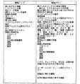
再書き込み可能なメモリチップ18が存在することによって、情報をメーターからスマートチップにダウンロードでき、さらに、情報をスマートチップからメーターへアップロードできる。スマートチップからメーターへアップロードされる情報の例には、以下に限定されないが、「較正コード」情報、「細片の数」情報、「細片バンクが開かれた」情報、「貯蔵寿命の期限」情報、「ロット/バッチ/細片の識別子」情報、使用者への「使用説明」、「ソフトウェア(アップグレードまたは修正)」、「制御解決策」情報、「国コードまたは国市場風趣」情報、「個人化」情報、例えば、メーターが若年および高齢の患者に対してまたはある患者から別の患者で異なる方法で相互に作用するように風趣を添えられる、「自己学習パラメーター」、例えば、前回までの検査結果からの情報が、例えば、具体的な使用者のヘマトクリット反応、または、食物摂取または運動などのその他の要因に対する具体的な患者の反応、を考慮に入れるために、具体的なその患者に対する改善されたアルゴリズムを開発するため、または、アルゴリズムの訂正をおこなうために、用いられる、「改定されたまたは新たな被検体計算アルゴリズムパラメーター」、これは、新たなメーターに対して工場で設定され、または、既存の使用者に対する前回までの検査結果に基づいて設定される、「前回までの検査結果」、記憶内容をチェックするための「チェックサム(CHECKSUM)」、ユーザーインターフェースのためのパラメーター、新たな製品に関する情報、現在の製品の性能に関する情報、などがある。 The presence of the
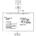
典型的には、例えば、ボタンを押す、キャップを開ける、細片を挿入する、細片バンクを挿入または接続する、などによって、メーターがスイッチオンされると、メーターは、再書き込み可能なメモリデバイスを読み出し、上記のタイプの情報の一つが、再書き込み可能なメモリデバイスからメーターへアップロードされる。典型的には、情報には少なくとも較正コードが含まれているが、最初のおよび残りの使用されていない細片の数などのその他のタイプの情報もアップロードされてよい。さらに、または、使用者が続いて検査を行うことを望む場合、使用者は、メーターを停止する前に検査を行うことかができる。典型的には、一回の検査の後に、「新カウント=旧細片カウント−1」のような情報が再書き込み可能なメモリデバイスにダウンロードされる。したがって、メーターが次回にスイッチオンされると、使用されていない細片の数または使用不可能な細片を検出するための機構が設けられている場合には使用可能な細片の数に関連する新細片カウントが、メーターにアップロードされる。典型的にはREAD/WRITEメモリデバイスに記憶されているその他の情報には、以下に限定されないが、例えば「検査結果、測定された電流、使用された較正コード、日、時間、細片数、バッチ/ロット数」などの検査結果、「日、食物のタイプ、量」などの食物に関連する情報、「日、薬のタイプ、量」などの薬に関連する情報、「日、運動のタイプ、量」などの運動に関連する情報、「状態のタイプ、経過」などの健康に関連する情報、「日、状態のタイプ、経過」などのストレスに関連する情報、「日、警報のタイプ、時間の長さ」などの低血糖の警報に関する情報、のような使用者によって入力されたその他の情報、「コンテナが開けられてからのカウントダウン」言い換えればセンサーのコンテナが開けられてからの日数、メーターのシリアル番号、前回までの検査結果からメーターによって計算された任意の自己学習被検体計算アルゴリズムのパラメーター、記憶内容をチェックするためのチェックサム(CHECKSUM)、ユーザーインターフェースのためのパラメーター、新製品に関する情報、現在の製品の性能に関する情報、などがある。その後、メーターはスイッチオフされてよい。再書き込み可能なメモリデバイスからアップロードされるまたはメモリデバイスへダウンロードされる情報のタイプの例、および、使用される方法は、図16A、図16B、図16C、図17、および、図19に示されている。 Typically, when a meter is switched on, for example by pressing a button, opening a cap, inserting a strip, inserting or connecting a strip bank, the meter is rewritten to a rewritable memory device. And one of the above types of information is uploaded from the rewritable memory device to the meter. Typically, the information includes at least a calibration code, but other types of information may be uploaded, such as the number of initial and remaining unused strips. In addition, or if the user wishes to perform a subsequent test, the user can perform the test before stopping the meter. Typically, after a single check, information such as “new count = old strip count−1” is downloaded to a rewritable memory device. Therefore, the next time the meter is switched on, it is related to the number of strips that are not used or, if a mechanism is provided to detect strips that are not usable. A new strip count is uploaded to the meter. Other information typically stored in a READ / WRITE memory device includes, but is not limited to, for example, “test results, measured current, calibration code used, date, time, number of strips, Test results such as “batch / lot number”, information related to food such as “day, type of food, quantity”, information related to medicine such as “day, type of medicine, quantity”, “day, type of exercise” Information related to exercise such as `` quantity '', information related to health such as `` condition type, course '', information related to stress such as `` day, condition type, course '', `` day, type of alarm, Other information entered by the user, such as information about hypoglycemia alarms, such as “length of time”, “countdown after opening the container” in other words, the number of days since the sensor container was opened, The serial number of the meter, the parameters of any self-learning subject calculation algorithm calculated by the meter from the previous test results, the checksum (CHECKSUM) to check the stored contents, the parameters for the user interface, and the new product Information, information about current product performance, etc. Thereafter, the meter may be switched off. Examples of the types of information uploaded from or downloaded to the rewritable memory device and the method used are shown in FIGS. 16A, 16B, 16C, 17, and 19. ing.
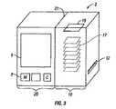
図3は、センサーバンク10および別個のメーター20を示している。この場合、センサーバンク10は、細片17のカートリッジであり、カートリッジには、スナップ嵌め固定構造21のようなメーター20との接続手段(図示されていない)が設けられている。ここでは、カートリッジ10およびメーター20は、互いに対応するように寸法および形状が与えられていて、滑らかな外形を備えた結合された装置2が提供される。細片バンク10のハウジングは、ポリプロピレン、または、ポリプロピレンをベースとするプラスチック、または、良好な水蒸気遮断特性を備えたその他のプラスチックまたはその他の材料で作られていてよい。再書き込み可能なメモリデバイスは、接着剤を用いてこの材料に接着されていてよく、接着剤には、低温硬化接着剤、感圧性接着剤、ヒートシール性接着剤、および、ホットメルト接着剤などが用いられる。低温硬化接着剤は、ある一定の時間内で、例えば600ミリ秒間で、ある付着強さ、例えば全体の40%の付着強さまで硬化し、この低温硬化接着剤が用いられてよい。 FIG. 3 shows a
図4は、システム2の例示的な実施の形態を示していて、システム2は、メーター20、および、センサーバンク10、を含み、メーター20およびセンサーバンク10は、無線式の接続を介して互いに通信を行い、情報リンク100,102を提供している。センサーバンク10は、検査の準備を整えるために開口12を通して供給される細片17の積層体を収容している。一旦細片が開口12から現れると、細片が使用者によって取り除かれ、細片は検査の準備を整えるために細片ポート13へ挿入される。窓11が、カートリッジ10のハウジングに設けられていて、細片バンク内に残っている細片の数の視覚的な表示を使用者が得られるようになっている。そのような窓は、本発明のセンサーバンクのいずれにも配置できるが、センサーの積層体が細片ごとに寸法を減らしてゆき、細片の数の減少を観測可能に表示しているセンサーバンクでは、とりわけ有益であることが見出される。窓は、任意の適切な透明な材料で作られていてよく、そのような材料の一つが、透明なポリプロピレン、または、ポリプロピレンをベースとする材料で、良好な水蒸気遮断特性を備えたものである。対応して配置された窓が、センサーバンクがメーター内に配置されたときに、センサーバンクの内側を目視するために、メーターに配置されていてもよい。 FIG. 4 shows an exemplary embodiment of the
スマートチップ18は、典型的には、2KバイトEEPROMであり、センサーカートリッジ10の側面に固定して取り付けられていて、一意の識別子コード「XXXX」が設けられている。識別子コードは、任意の個数のディジット、文字、および/または、番号、を含んでいてよく、または、任意の基数またはコードであって、別の装置によって認識可能な一意の識別子コードを提供するようになっていてもよい。空中線および受信機24が、情報リンク100,102を介して無線式で情報を伝達するために、設けられている。メーター20には、スマートチップ18からの一意の識別子コード22を認識できるマイクロプロセッサ28が設けられている。典型的には、スマートチップ18は、細片17に対する較正コードを、情報リンク100を介してメーター20に送る。同様に、「検査結果」、「細片の数」、などに関する情報は、再書き込み可能なメモリデバイス18へダウンロードできる。細片の数の情報は、この実施の形態では、必要な場合に用いられ、その理由は、細片の数の物理的な減少は窓を通して観察することができ、使用者はその窓を利用するからである。メーター20には、情報リンク100,102を介して情報を供給および受信するための伝達および受信手段26が設けられている。 The
別の実施の形態では、本発明に基づくシステムは、メーターおよび別個のセンサーバンクを含み、別個のセンサーバンクは、メーターとドッキングされたときにメーター内に細片を装填するための機構を有している。この実施の形態は、どのような追加の過程もなしに、較正コードの情報をメーターにトランスペアレントに供給する。 In another embodiment, a system according to the present invention includes a meter and a separate sensor bank, the separate sensor bank having a mechanism for loading a strip into the meter when docked with the meter. ing. This embodiment transparently supplies calibration code information to the meter without any additional steps.
センサーバンク、例えば、細片のバイアルには、近接メモリが設けられ、メーターには、このメモリに対する読み出し/書き込みを行うための手段が設けられている。特別に設計された細片バイアルには、近接メモリ、および、例えば細片供給機構などのグルコースメーターに細片を装填するための手段、が設けられていて、細片を装填するための手段は、メーターとドッキングされたときに細片を供給する。細片を装填するためにバイアルをメーターに接近して配置することによって、メーターの電子回路が近接メモリの内容を読み取り内容を書き込む機会が提供される。 Sensor banks, for example strip vials, are provided with proximity memory and the meter is provided with means for reading / writing to this memory. Specially designed strip vials are provided with proximity memory and means for loading the strips into a glucose meter, for example a strip feeding mechanism, the means for loading the strips is Deliver strips when docked with meter. Placing the vial close to the meter to load the strip provides an opportunity for the meter electronics to read the contents of the proximity memory and write the contents.
典型的には、BiStatix(商標)メモリおよびその他の近接メモリデバイスは、バーコードの識別子の代わりとして、無線周波数の識別子(RFID)を提供する。RFIDは、誘導性の原理で働く。磁界が予め決められた周波数で生み出される。近接メモリデバイスが、磁界中に入ると、小さな電流が、コイルおよびキャパシターを含むメモリデバイスの回路内に生まれる。電力がマイクロプロセッサに供給され、マイクロプロセッサが磁界を変調して、チップ内に予めプログラムされたデータをリーダーへ伝送する。この例では、リーダーは、メーターに取り付けられていて、RFIDデバイスは細片のバイアルまたは細片カートリッジに配置されている。 Typically, BiStatix ™ memory and other proximity memory devices provide radio frequency identifiers (RFIDs) instead of barcode identifiers. RFID works on an inductive principle. A magnetic field is generated at a predetermined frequency. When a proximity memory device enters the magnetic field, a small current is generated in the memory device's circuit including the coil and capacitor. Power is supplied to the microprocessor, which modulates the magnetic field and transmits data preprogrammed in the chip to the reader. In this example, the reader is attached to a meter and the RFID device is placed in a strip vial or strip cartridge.
使用される近接メモリの一例は、アメリカ合衆国のモトローラー・インコーポレイテッド(Motorola Inc.)から入手可能なBiStatix(商標)技術、または、アメリカ合衆国のエイリアン・テクノロジー(Alien Technology)から入手可能な915MHzRFIDタグ、である。細片装填手段(図示されていない)を用いて細片を装填するためにバイアルをメーターの近くに配置することによって、メーターの電子回路が近接メモリの内容に対する読み出しまたは書き込みを行う機会が提供される。このバイアルの付近との相互作用は、使用者にはトランスペアレントであり、使用者による追加の行動をまったく必要としない。次に、メーターは、較正コードおよび任意のその他の関連する情報を細片装填ステップの間に近接メモリから読み取る。メモリ18は、何れの場所でも、約4バイトから100バイト以上の情報を収容できる。典型的には、このメモリは、較正コードの値、または、生のグルコースの結果を報告されるグルコースの結果に変換する媒介変数方程式のための値、を収容している。記憶されるその他の有用な情報には、バイアルの有効期限、バイアル内の残りの細片数、最初の細片がバイアルから取り出された日(開封後のバイアルの有効期限を突きとめるために用いられる。)、ロットコード情報など、がある。メモリ18は、CRC、チェックサム(CHECKSUM)、または、記憶内容を確認するための手段、などをさらに収容していてもよい。これらの情報は、グルコースの結果の信頼性を高めるため、および、製品の誤使用の発生率を減らすために用いられる。さらに、情報は近接メモリに書き込まれてもよい。 An example of proximity memory used is BiStatix ™ technology available from Motorola Inc., USA, or a 915 MHz RFID tag available from Alien Technology, USA . Placing the vial close to the meter to load the strip using strip loading means (not shown) provides an opportunity for the meter electronics to read or write to the contents of the proximity memory. The This interaction with the vicinity of the vial is transparent to the user and does not require any additional action by the user. The meter then reads the calibration code and any other relevant information from the proximity memory during the strip loading step. The
さらに、または、代わりに、EEPROMのような再書き込み可能なメモリおよびマイクロプロセッサまたはマイクロコントローラ(典型的には、マイクロプロセッサはそれ自体のメモリおよび適切なポート接続部を備えている。)を組み込んだ「賢い」メモリデバイスが、用いられてもよい。したがって、再書き込み可能なメモリデバイスは、データ記憶および検索能力、および、ローカルなソフトウェア実行能力、を備えている。そのようなデバイスは、再書き込み可能なメモリデバイス18を形成し、READ/WRITE記憶機能に加えて、簡単な演算すなわち計算を請け負うことができる。より詳しく言うと、そのようなデバイスは、ソフトウェアの、より詳しくは、ユーザーインターフェースおよび/または計算アルゴリズムに関連するソフトウェアの、アップグレードを援助し、アップグレードが成功したか否かの識別力を有するチェック(intelligent check)を可能にする。「賢い」メモリは、状態(アップグレードの成功、失敗、など。)を検証するために製造業者に送り返すことができる。そのようなデバイスには、アメリカ合衆国カリフォルニア州のアトメル(ATMEL)から入手可能な、96KバイトのROMプログラムメモリ、8KバイトのEEPROM、および、3KバイトのRAMを有するAT90SC9608RC(スマートカード用の保証マイクロコントローラ)、日本国東京の日立株式会社およびアメリカ合衆国のヒタチ・アメリカ・リミッテッドから入手可能なAE46C(68KBのEEPROM、160KBのROM、および、6KBのRAM、および、1024ビットのコプロセッサを備えたスマートカード集積回路)などがある。 Additionally or alternatively, it incorporates a rewritable memory such as an EEPROM and a microprocessor or microcontroller (typically, the microprocessor has its own memory and appropriate port connections). A “smart” memory device may be used. Thus, a rewritable memory device has data storage and retrieval capabilities and local software execution capabilities. Such a device forms a
図5および図6は、本発明に基づく別のセンサーバンクの平面図および側面図である。ここで、センサーバンク10は、センサー17Aからセンサー17Kを含む実質的に円形の円盤10の形態で提供されている。各センサーは、製造中にその隣のセンサーと物理的に結合されて円盤を形成し、または、円盤を形成するために、細片などのセンサーを基板上に配置する製造プロセスが用いられてもよい。スマートチップ18は、例えば接着剤を用いて、円盤の基部に固定して結合される。 5 and 6 are plan and side views of another sensor bank according to the present invention. Here, the
血液または間質液などの流体サンプルが、センサーの検査領域29に供給するために、毛細管32の入口に配置される。各センサーは、順番に用いられる。ノッチすなわち凹部34,36,38が、例えば使用者の指を、センサーの近くに配置することを援助して、サンプルの流体を毛細管32に供給するのを容易にしている。ノッチ38は、とりわけ、鋭利な角部を提供し、その角部がノッチ38に提供された流体の一滴の表面張力を破壊して、流体が毛細管32内に進入するのを援助する。そのようなセンサーバンクは、例えば、導電性パスを提供するためのカーボンインク、絶縁性インク、例えば酵素を含む試薬インク、接着剤インク、などの適切なインクを用いて、スクリーン印刷されてよい。そのようなバンクは、平盤プロセス、または、2001年3月28日に出願された国際特許出願PCT/US01/10097、公開番号WO01/73109「使い捨て式の電気化学的センサーの製造のための連続プロセス(Continuous Process for the Manufacture of Disposable Electrochemical Sensors)」(代理人整理番号DDI−010PCT)、2002年12月27日に出願された米国仮特許出願60/436,683「使い捨て式の電気化学的センサーの製造のためのプロセスでの移動式平盤スクリーン印刷(Movable Flat Screen Printing in a Process for Manufacture of Disposable Electrochemical Sensors)」(代理人整理番号DDI−5001US)、および、2002年10月30日に出願された米国仮特許出願60/422,230「連続ウエブプロセス中の基板の試験準備(Preconditioning of the substrate in a continuous web process)」(代理人整理番号DDI−047USA)に記載されたもののような製造の連続プロセス、によって、生み出されてもよい。 A fluid sample, such as blood or interstitial fluid, is placed at the inlet of the capillary 32 for delivery to the
図5では、スマートカード18は接着剤23によってセンサーバンク10に固定されている。接着剤23は、低温硬化接着剤、感圧性接着剤、ヒートシール性接着剤、または、ホットメルト接着剤、であってよい。実質的に円形の円盤10は中心開口25を有し、中心開口25は装置がメーター内に配置されるようにしている。スマートチップ18は、円盤10の下側に非対称的に配置されている。スマートカード18は中心開口25に関して対称的に配置されていてよく、または、スマートカード18の接続部が中心配置開口25に関して対称的に配置されていてよい。バンク10は、スマートチップが取り付けられることがあるメーター内またはハウジング内で回転可能であってよい。 In FIG. 5, the
図7は、メーター20の斜視図であり、試験細片カートリッジ10の形態のセンサーバンクは、試験細片センサー17の積層体および一意の識別子コード「XXXX」22を含んでいる。別個のスマートチップ18は、典型的には、カードホルダー30に取り付けられて提供されていて、スマートチップ18およびスマートチップカードホルダー30のいずれか一方または両方には一意の識別子コード「XXXX」が設けられている。例えば、コード22はカードホルダー30上に表示されている場合、人が読み取れる形態であってよく、または、もちろん、バーコードの形態のような機械が読み取れる形態であってもよい。その代わりに、または、それに加えて、識別子コードは、スマートチップ18に機械が読み取れる形態で設けられていてもよい。スマートチップ18は、カードホルダー30に取り付けられる。典型的には、カードホルダー30は、約55mmの幅、約87mmの長さの、クレジットカードの寸法および形状である。メーター20には、ディスプレイ6およびいくつかのボタンが設けられていて、それによって、使用者の行動に関する情報が、制御ボタンを押すことによって直ちに入力できるようになっている。例えば、ボタン41は患者の健康に関して情報を入力できるようにし、ボタン42は患者の薬に関してメーターに情報を入力できるようにし、ボタン44は患者の食物摂取に関して情報を入力できるようにし、ボタン46は患者の運動に関して情報を入力できるようにしている。残りのボタン8は、メーターをスイッチオンし、そしてメーターをスイッチオフし、測定を行うために、用いられる。 FIG. 7 is a perspective view of
矢印104の向きでメーター20を見たメーター20の基部の図が、図8に示されている。図8は、センサーバンク10をメーター20に取り外し可能に挿入するためのスロット56を示している。典型的には、ドア(図示されていない)が設けられている。スロット54は、カード30をメーター20に取り外し可能に挿入するために設けられている。必要な場合には、ドア(図示されていない)がスロット54を閉じるために設けられている。バンク10およびカード30の両方は、一意の識別子コード「XXXX」を保持している。この実施の形態では、一意の識別子コード22は、人が読み取れる形態で図示されているが、その代わりに、または、それに加えて、識別子コードは、スマートチップ18と離れた別個の機械が読み取れる形態でもよい。その代わりに、または、それに加えて、スマートチップ18は、この一意の識別子コードを機械が読み取れる形態で含んでいてもよい。 A view of the base of
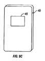
図9A、図9B、および、図9Cは、メーター20、細片バンク10、および、クレジットカードサイズのスマートチップキャリア40の斜視図である。本発明のこの実施の形態では、2つの再書き込み可能なメモリデバイスが、ここでは、スマートチップの形態で、設けられている。一方のスマートチップは、細片バンク10のハウジングに物理的に固定して取り付けられていて、物理的な方法で細片バンク10のハウジング内に収容された試験細片17に一意に関連付けられていて、第2のスマートチップ48は、別個の、この場合はクレジットカードサイズの、カードキャリア40に取りけられている。スロット54,56は、各々、クレジットカードサイズのスマートチップキャリア40および細片カートリッジ10をメーター20内に取り出し可能に受容する寸法および形状である。2つのスマートチップを準備し、そのうちの一方が細片カートリッジに物理的に結合され、第2のスマートチップが別個の移動可能なカードキャリアに配置されていることは、後により詳しく記載されるようにある一定の利点を有する。 9A, 9B, and 9C are perspective views of the
本発明の多くの利点は、生理学的サンプルのような流体中の被検体を分析するための少なくとも2つの試験細片、そして、典型的には試験細片の集合をスマートチップのような再書き込み可能なメモリデバイスに半永久的な形態で結合することから生ずる。 Many advantages of the present invention are that at least two test strips for analyzing an analyte in a fluid, such as a physiological sample, and typically a rewrite of a collection of test strips, such as a smart chip. Results from coupling to possible memory devices in a semi-permanent form.
結合は、物理的であっても無線式であってもよく、しかし、典型的には、結合は、メモリデバイスに収容された情報と検査センサーの集合との間のほとんど壊れない関連を生み出す。したがって、もしもスマートチップ18がバイアル10の側面から剥がれると、そのバイアルは事実上使用できなくなる。さらに、もしもある一意の識別子を備えたバイアル10が用いられ、別の一意の識別子を備えたスマートチップ18が用いられると、メーター20を用いた検査は典型的には差し止められる。したがって、製造中に、半永久的な関連が検査センサーの集合と再書き込み可能なメモリデバイスとの間に形成される。もちろん、試験細片のような、個々の検査センサーには、それぞれバンクの一意の識別子が設けられていてもよい。これは、無線式の構成ではとりわけ有益な、再書き込み可能なメモリ、センサーバンク、および、センサーの間の関連に特別な安全確保を提供できる。検査センサーと情報との間のこのような関連は、再書き込み可能なメモリデバイスからメーターへアップロードされる情報、および、再書き込み可能なメモリへダウンロードされる情報に対しても存在する。例えば、試験細片からの結果の精度の喪失を結果としてもたらす、製造中のばらつきに関連する情報が、スマートチップにロードされ、その情報と関連する試験細片に関連して用いられるメーターによって読み取られる。したがって、その情報および試験細片の間の関係が、製造中に、制御され調整された形式で求められ、検査の間および検査結果の取り扱いの間保持される。かなり安全なシステムが、本発明によって提供され、そのシステムでは、試験細片に関連する情報が、メーターのマイクロプロセッサへ、および、マイクロプロセッサから、明瞭にそして典型的にはそれらの試験細片と一意に関連付けられたスマートチップを介して運ばれる。明らかに、これは、スマートチップが細片バンクに、例えば、センサーバンクのハウジングまたはセンサーの集合に、固定して取り付けられた物理的な形式で達成される。その代わりに、これは、図1Bに示された実施の形態でのように一意の識別子コードをセンサーバンク内および再書き込み可能なメモリデバイスキャリア内にまたはもちろん再書き込み可能なメモリデバイス内に設けることによって、わずかに安全性が少ない程度で、無線式の形式で達成される。 The coupling may be physical or wireless, but typically the coupling creates an almost unbreakable association between the information contained in the memory device and the collection of test sensors. Thus, if the
スマートチップを細片バンクに物理的に接続することによって、誤ったスマートチップが、したがって正しくない較正コードのような情報が、細片の集合に意図せずに関連付けられるリスクがさらに減らされる。これは、細片バンクが、カートリッジのように細片が一つずつ供給されるのではない例えばバイアルの細片のようなばらばらの細片の集合を収容している場合に、とりわけ当てはまる。スマートチップが誤った試験細片と関連付けられるリスクは、細片バンクがメーターに物理的に接続されまたはメーターに物理的に充填され、試験細片を供給する手段が試験細片を一つずつメーターに供給するように提供されている場合に、さらに低減される。スマートチップ上の誤った情報が試験細片の集合に関連付けられるリスクは、たったいま記載されたシナリオで、試験細片カートリッジを試験細片ポートへ供給する手段がメーター内に設けられていると、さらに低減される。したがって、一旦試験細片カートリッジがメーターに挿入されると、使用者は試験細片カートリッジにアクセスすることを許されない。したがって、メーターのマイクロプロセッサが、その試験細片コンテナ内のその集合の細片に関連したスマートチップにアクセスし、その情報がその試験細片からの生のデータをグルコース測定値に変換するために用いられて、グルコース測定値がディスプレイ6上で患者によって目視される。したがって、本発明のシステムは、試験細片の集合が細片バンクの形態で提供され、スマートチップが細片バンクに物理的に結合され、細片バンクがメーター20に挿入可能で、挿入された後は、サンプルを、典型的には血液を加えることによる検査の準備を整えるために、細片が検査ポートに供給される、例および実施の形態で、とりわけ安全性が高い。さらに、それらの細片に対する検査結果からの情報または更新された細片カウントが、これらの細片に関連するスマートチップに書き込まれる。 By physically connecting the smart chip to the strip bank, the risk that an incorrect smart chip and thus incorrect calibration code, such as information, is unintentionally associated with a collection of strips is further reduced. This is especially true when the strip bank contains a collection of discrete strips, such as vial strips, where the strips are not supplied one at a time like a cartridge. The risk that a smart chip is associated with an incorrect test strip is that the strip bank is physically connected to or filled with the meter, and the means for supplying the test strip is metered one by one. Is further reduced if provided. The risk that incorrect information on a smart chip is associated with a collection of test strips is the scenario just described, and if there is a means in the meter to supply a test strip cartridge to the test strip port, Further reduced. Thus, once the test strip cartridge is inserted into the meter, the user is not allowed access to the test strip cartridge. Thus, the meter's microprocessor has access to the smart chip associated with the set of strips in the test strip container and the information converts the raw data from the test strip into glucose measurements. Used, the glucose reading is viewed by the patient on the
本発明は、血液中のグルコースの濃度の検査にとりわけその用途を見出すが、本発明のその他の用途が本明細書に含まれる記載から考えられ、例えば、血液または間質液中のグルコースまたはフルクトサミン、または、尿中のグルコース、または、血液中のヘモグロビン、血液、間質液、または、尿中のその他のホルモン、または、その他の生理学的流体中のその他の被検体、の検出などが考えられる。 While the present invention finds its use in particular for testing the concentration of glucose in blood, other uses of the present invention are contemplated from the description contained herein, for example, glucose or fructosamine in blood or interstitial fluid Or detection of glucose in urine, hemoglobin in blood, blood, interstitial fluid, or other hormones in urine, or other analytes in other physiological fluids, etc. .
本発明のいくつかの実施の形態は、センサーバンク10に物理的にまたは無線式で関連付けられた一つのみのスマートチップ18を有しているが、別の実施の形態は2つのスマートチップを用いることが考えられる。スマートチップなどの一つの再書き込み可能なメモリデバイスが用いられている場合、このスマートチップ、および、典型的にはスマートチップのキャリアまたはスマートチップが取り付けられている細片のコンテナは、家庭でまたは臨床医の診療所で、パーソナルコンピューターにダウンロードするために、スマートカードリーダーへ運ばれる。したがって、検査および患者に関する情報は、追加の費用はほどんどなしに、分析のためにメモリリーダーに簡単かつ容易に移送される。 While some embodiments of the present invention have only one
図9に示された実施の形態は、センサーバンク10に物理的に取り付けられたスマートチップ18のような第1の再書き込み可能なメモリデバイスと、別個のカードキャリア40に取りけられたスマートチップ48のような第2の再書き込み可能なメモリデバイスと、を用いている。したがって、メーター20内に収容されたマイクロプロセッサからの検査結果は、第1のスマートチップ18内にまたは第2のスマートチップ48内に記憶される。もちろん、スマートチップの典型的なサイズは、1KBまたはそれ以上であるが、第2のスマートチップ48が第1のスマートチップ18よりも大きな容量を有することが考えられる。したがって、いずれかのスマートチップが、結果を、スマートチップリーダーへ運ぶために、パーソナルコンピューターまたはインターネットへダウンロードするために、用いられてよい。もちろん、いずれかのスマートチップが使用者によって臨床医の診療所へ運ばれて、診療所でスマートチップがスマートカードリーダーによって読み取られ、臨床医のパーソナルコンピューターへダウンロードされてもよい。したがって、本発明はスマートチップを用いてデータを移送する方法を提供する。 The embodiment shown in FIG. 9 includes a first rewritable memory device such as a
スマートチップを細片バンクの側面に取り付けることは、較正コード(細片の検査の間に用いられる。)のようなメーターにアップロードされる情報の混同のリスクの低減に関する利点、あるいはメーターからスマートチップへダウンロードされる情報(そのバッチの細片から得られる検査結果など)に対する利点、および、情報の取り扱い、移送、および細片の集合との関連付けをより安全にすることに関する利点を有する。しかし、細片の積層体および細片カートリッジ10の形状は持ち歩くには少々扱いにくい。したがって、患者は、図5に示されているもののような再書き込み可能なメモリデバイスが取り付けられた細片バンク10、または、図7に見られる別個のカードキャリア30、を用いることをより好むかもしれない。 Attaching the smart chip to the side of the strip bank is an advantage in reducing the risk of confusing information uploaded to the meter, such as a calibration code (used during strip inspection), or from the meter to the smart chip Has the advantage over information downloaded to the network (such as the test results obtained from that batch of strips) and the security of handling, transporting, and associating the collection with a collection of strips. However, the shape of the stack of strips and the
図5に示されているようなセンサーバンクは、複数回の検査が行われた後は、バイオハザードであることが考慮されるので、ポーチまたはその他のコンテナ(図示されていない)が、センサーバンクをポーチまたはコンテナに挿入して、後に、その再書き込み可能なメモリデバイスを読み取るための再書き込み可能なメモリリーダーを備えた臨床医の診療所またはその他の場所に運ぶために、準備されてよい。図9に示された実施の形態は、センサーバンク10に物理的に固定されて取り付けられたスマートチップと別個の通常のサイズのスマートチップカードリーダーとの利点を組み合わせている。この例に示されたキャリア40は、クレジットカードの寸法および形状である。さらに、第2のチップキャリアを設けることによって、異なるサイズのメモリの、したがって異なる価格のスマートチップの使用が可能になる。したがって、スマートチップ18は、最近6カ月分の検査またはもちろん1年分の検査、および、本明細書で上述されたような、較正コード、ロットコード、検査で開けられたコンテナの寿命、健康、食物、患者の運動の状態、などの全ての関連するデータをも保持するのに十分なサイズであるかもしれないが、スマートチップ48は、特に、個人によってより長期間に亘って用いられる場合には、より大きくより高価であってもよい。典型的には、再書き込み可能なメモリデバイス18は、必要な場合には、デバイス内の細片が使い尽くされて、スマートチップからのデータが適切な記憶/分析装置にダウンロードされた後に、廃棄されるであろう。しかし、カード40および再書き込み可能なメモリデバイス48は、より長い期間に亘って、例えば、細片バンク10内の細片の集合の50個に対して、数ヶ月、または、数年に亘って、使用でき、したがって、スマートチップキャリア40は、例えば、財布に収まるクレジットカードサイズの便利に携行できる寸法および形状の、患者に固有の検査データの個人口座であるともいえる。もちろん、その他のサイズのスマートカードキャリア40も本発明の範囲内にあると考えられる。 A sensor bank such as that shown in FIG. 5 is considered a biohazard after multiple tests have been performed, so a pouch or other container (not shown) is attached to the sensor bank. May be inserted into the pouch or container and later prepared for transport to a clinician's clinic or other location with a rewritable memory reader for reading the rewritable memory device. The embodiment shown in FIG. 9 combines the advantages of a smart chip physically fixedly attached to the
細片の集合に関連する再書き込み可能なメモリデバイスを用いる別の利点は、ソフトウェアのアップグレードまたは修正に関連する情報が再書き込み可能なメモリデバイスに保持できることである。より詳しく言うと、ダミーのセンサーバンク10が、ソフトウェアのアップグレード、より詳しく言うと、アルゴリズム計算ソフトウェアのユーザーインターフェースソフトウェア、または修正、またはソフトウェアの個人化をメーターにアップロードするための、通常の容量よりも大きな再書き込み可能なメモリデバイスを保持して、提供される。この場合、ダミーセンサーバンクは、どのようなセンサーも含まず、または、ダミーのセンサーのみを含む。子供はとりわけ個人化されたソフトウェアから利益を受け、個人化されたソフトウェアは子供の年齢に適した方法で子供との会話を行う。それに代わって、真のセンサーバンク10には、またはダミーのセンサーバンクにでさえも、具体的な国または言語のために、または、もちろん、患者のためのアップデートされた情報を提供するために、メーターに風趣を添えるために国または言語データを有するスマートチップなどの再書き込み可能なメモリデバイスが設けられていてよい。したがって、再書き込み可能なメモリデバイスのサイズ(および、したがってコスト)は、必要とされる具体的な用途に適するように変えられてよい。 Another advantage of using a rewritable memory device associated with a collection of strips is that information associated with software upgrades or modifications can be retained in the rewritable memory device. More specifically, the
図10Aは、メーター20は、ディスプレイ6、ランセット58、および、細片供給シュート60を含む、組み合わされたランセットおよびメーター20を示している。 FIG. 10A shows the combined lancet and
図10Bは、積層された細片のカートリッジ10Aを組み込んだ図10Aの組み合わされたランセットおよびメーター20の切り欠き図である。ランセット駆動列62およびランセット58を含んだランセットが設けられている。ランセット58は、駆動列62によって開口64を通して使用者の皮膚内に向けて発射されて血液を引き出す。細片はシュート62を通して、開口64、および、典型的には切開の後に形成される血液の一滴、に隣接した位置に供給さる。細片カートリッジ10Aは、カートリッジ10Aのハウジングに対して斜めの角度で細片17の積層体を収容している。スマートチップ18は、カートリッジ10Aの側面に接着されている。 10B is a cutaway view of the combined lancet and
図11は、細片ディスペンサーに固定して取り付けられたスマートチップ18を有する細片ディスペンサーを組み込んだメーター20の別の例を示している。 FIG. 11 shows another example of a
図12は、細片カートリッジ10Aの片側を拡大して示した側面図であり、スマートチップ18がハウジング10Aの側面の整合した大きさの凹部18A内に配置されているのを示している。スマートチップ18は、典型的には、接着剤によって、カートリッジ10Aの側面に接着されている。カートリッジ10Aのハウジングは、ポリプロピレンで形成されていて、ポリプロピレンは、水蒸気が試験細片17に進入するのを防ぐのに有効な低い水蒸気透過特性を有している。 FIG. 12 is an enlarged side view of one side of the
図13は、例示的なスマートチップ18をより詳細に示していて、この場合、スマートチップは、アトメル(Atmel)から入手されるEEPROMスマートカードであり、接触ピンの詳細な識別が示されている。 FIG. 13 shows an exemplary
図14は、プリント回路基板20Bおよびマイクロプロセッサ200を有するメーター20Aを示した模式的なブロック図である。矢印106は、細片カートリッジ10Aをメーター20Aに挿入する向きを示している。パネル10Bは、人が読み取り可能なコードをカートリッジ10Aに取り付けるまたは印刷するために、カートリッジ10Aの片方の側面に設けられている。スマートチップ18は、カートリッジ10Aの下側10Cに配置されている。スマートチップ18は、矢印105の向きに回されて、メーター20A内のピンと接触するようになる。したがって、チップ18の表面のピン201A、202A、203Aは、メーター20Aのパッド201B、202B、203Bと接触する。 FIG. 14 is a schematic block diagram showing a
図15は、細片カートリッジ10およびスマートチップ18の斜視図であり、より詳しく言うと、その中でスマートチップ18が細片カートリッジ10のハウジングに配置された凹部18Aをより詳細に示している。感圧性接着剤、ヒートシール接着剤、またはホットメルト接着剤のような典型的な接着剤が、スマートチップをカートリッジ10のハウジングに取り付けるために用いられている。 FIG. 15 is a perspective view of the
典型的には、再書き込み可能なメモリは、EEPROM(電子的に消去可能なプログラム可能読み出し専用メモリ)のフォーマットのスマートチップである。そのようなデバイスは、その記憶内容を維持するための電力を必要としない。 Typically, the rewritable memory is a smart chip in the form of an EEPROM (electronically erasable programmable read only memory). Such a device does not require power to maintain its stored contents.
図16A、図16B、および、図16Cは、細片バンク10をメーター20に挿入または結合した後に、追従される、一連の過程を示していて、当業者には理解されるように、いずれの過程も、必要な場合に行われるものである。情報のひとつまたは複数のアイテムは、典型的には細片バンクのスマートチップからメーターへアップロードされることが、当業者には本明細書に含まれる情報から理解されるであろう。典型的には、この情報は、較正コードであり、したがって、メーターを新たなバッチの細片に対して較正する過程は、使用者に対してトランスペアレントにされている。細片のいくつかのみが使用されたときに細片バンクがメーターから取り除かれまたは切り離された場合、本発明の有用な用途は、細片バンク内に残っている細片の数をメモリデバイスにダウンロードすることである。部分的に使用された細片バンクが再び結合されると、残りの細片数が、関連する再書き込み可能なメモリからアップロードされる。その他の可能性には、いくつかのみの細片が使用可能な細片バンクの使用などがある。これらの細片は、使用可能な細片の位置およびタイプに関する情報がスマートチップ内に収容されていれば、配置され使用できる。したがって、細片バンク内の他の状態で使用できない細片の集合は、再書き込み可能なメモリデバイスがこれらの使用可能な細片の位置をメーターに対して特定することができれば、使用することができる。そのような構成は、図5および図6に示されたもののようなセンサーバンクでとりわけ有用な用途を見出すであろう。 FIGS. 16A, 16B, and 16C illustrate a series of processes that are followed after inserting or
図17は、検査の完了時にセンサーバンクにダウンロードされる情報のタイプ、および、検査中に行われる過程、を示している。図16Aから図16Cの過程が図17の過程と接続される点が、「C」で示されている。情報のひとつまたは複数のアイテムが検査の完了時またはスイッチオフの直前にメーターから細片バンクの再書き込み可能なメモリデバイスへダウンロードされることが、本明細書に含まれている内容から当業者には理解されるであろう。 FIG. 17 shows the type of information downloaded to the sensor bank upon completion of the test and the process that takes place during the test. A point where the processes of FIGS. 16A to 16C are connected to the process of FIG. 17 is indicated by “C”. It will be apparent to those skilled in the art from what is included herein that one or more items of information are downloaded from the meter to a rewritable memory device in the strip bank upon completion of inspection or immediately prior to switching off. Will be understood.
図18は、さまざまなレベルの細片バンク10のパッケージングに取り付けられる情報のタイプを示す模式図である。50個の細片17の集合が、主要部分206および蓋部分208を備えた完成したディスペンサー10内に装填される前に、内部カセット204内に装填される。バッチ番号、コード番号、列番号、および、年を詳しく記載した2Dマトリックスコードのような情報が、内部カセット204の外側に印刷されている。一旦内部カセット204がカートリッジハウジング206内に装填されると、2Dマトリックスコードが外側に印刷されて、バッチ番号、および、有効期限を表示する。さらに、人が読み取れるコードが印刷されて、バッチ番号、および、有効期限、を詳しく記載する。さらに、自動較正スマートチップ18が、後方チャネルに固定され、スマートチップ18内の再書き込み可能なメモリには、バッチ番号、有効期限、較正コード、および、制御または較正解決策データ、が収容されている。自動較正は、使用者による介入を最小にしながら、メーターへの較正コードのアップロードを自動的に行うものである。最後に、細片バンク10が、販売の準備を整えるために包装される。フローラップ(フォイルラップであってよい。)の外側には、バッチ番号、有効期限、および、商標をつける目的のその他の識別のための詳細な記載、が印刷されている。 FIG. 18 is a schematic diagram showing the types of information attached to various levels of
図19は、再書き込み可能なメモリデバイスからメーターへアップロードされる情報のタイプ、および、患者または臨床医によって後に使用されるために、または、さらに検査の間に使用するために、メーターから再書き込み可能なメモリデバイスへ書き込まれる情報のタイプ、を詳しく記載している。当該分野のメーターのソフトウェアはアップグレードされなければならないかも知れず、本発明は、少なくとも3つのタイプの変更を行うために用いられてよい。これらの変更は、問題点を直すための「修正的な」変更、そのソフトウェアが実行される環境に対する変更(例えば、調整的な変更)という観点でのソフトウェアを変更するための「適応的な」変更、および、新しい特徴を加えるためにソフトウェアを変更するための「完全な」変更の3つである。本発明は、国コード、個人化されたまたは国の風趣を添えられたソフトウェア、ソフトウェアのアップグレード、および、将来の検査のために検査アルゴリズムをアップデートするための前回までの検査結果に関連するパラメーターを用いて、メーターに動的に風趣を添える方法をも提供する。さらに、本発明は、関連するスマートカードのような再書き込み可能なメモリデバイスと共に細片バンクを除去し、ソフトウェアアプリケーションへダウンロードするために、細片バンクを臨床医の診療所のまたは家庭のパーソナルコンピューターに運ぶことによって、検査結果を臨床医の診療所でダウンロードする方法を提供する。さらに、本発明は、検査結果を記録するための臨床的な検査方法、および、前回までの検査結果に基づいてパラメーターを更新する方法、を提供する。本発明の方法の一つの利点は、再書き込み可能なメモリデバイス内の利用可能な空間がメーター内のマイクロプロセッサで通常利用可能な空間をはるかに超え、したがって、長期間に亘る検査結果が測定でき、加えて、健康、食物、運動、患者に関連するデータ、検査の時間、検査コンテナが開けられた時間、有効期限に対する検査の時間、などの臨床的な詳しいデータを提供する、その検査結果に関連するデータがさらに記憶できることである。さらに、本発明は、物理的にまたは無線式で、細片を、較正コードを保持した再書き込み可能なメモリデバイスに結合する方法を提供する。さらに、本発明は、例えばソフトウェアのアップグレードを運ぶために、特別のメモリまたはマイクロプロセッサまたはマイクロコントローラなどの特別のコンポーネントを備えた再書き込み可能なメモリデバイスを保持したダミーのディスペンサーまたはダミーの細片バンクのような、ダミーのセンサーバンクを用いることができる能力を提供する。本発明は、細片バンクの再書き込み可能なメモリデバイスに収容された情報を読み出すために、細片バンクを受容するように適合されたスマートカードリーダーをも提供する。さらに、本発明は、再書き込み可能なメモリ、および、必要な場合には、センサーの集合に関連する「賢い」メモリおよび/または「近接」メモリを提供するために、マイクロプロセッサ、および/または、近接コンポーネント、を含んだ、再書き込み可能なメモリデバイスを備えたセンサーバンクを用いるシステムを提供する。 FIG. 19 shows the type of information uploaded from a rewritable memory device to the meter and rewritten from the meter for later use by the patient or clinician or for further use during the examination. Describes in detail the type of information written to a possible memory device. Meter software in the field may need to be upgraded, and the present invention may be used to make at least three types of changes. These changes are "adaptive" to change the software in terms of "corrective" changes to correct the problem and changes to the environment in which the software is run (eg, coordinated changes). There are three changes: a “complete” change to change the software to add new features. The present invention provides parameters related to country codes, personalized or country-inspired software, software upgrades, and previous inspection results for updating inspection algorithms for future inspections. It also provides a way to dynamically add a touch to the meter. In addition, the present invention provides a strip bank for use in a clinician's clinic or home personal computer for removal and download to a software application with a rewritable memory device such as an associated smart card. Provides a way to download test results at a clinician's clinic. Furthermore, the present invention provides a clinical test method for recording test results and a method for updating parameters based on previous test results. One advantage of the method of the present invention is that the available space in the rewritable memory device far exceeds the space normally available on the microprocessor in the meter, so that long-term test results can be measured. , In addition to providing clinical details such as health, food, exercise, patient related data, test time, time the test container was opened, test time to expiration, etc. The relevant data can be stored further. In addition, the present invention provides a method for coupling a strip to a rewritable memory device that holds a calibration code, either physically or wirelessly. Furthermore, the present invention provides a dummy dispenser or dummy strip bank holding a rewritable memory device with a special memory or special component such as a microprocessor or microcontroller, for example to carry software upgrades. Provides the ability to use a dummy sensor bank. The present invention also provides a smart card reader adapted to receive a strip bank for reading information contained in a rewritable memory device of the strip bank. In addition, the present invention provides a microprocessor and / or to provide rewritable memory and, if necessary, “smart” memory and / or “proximity” memory associated with a collection of sensors. A system using a sensor bank with a rewritable memory device including a proximity component is provided.
さらに別の態様では、本発明は、例えば、本明細書で上述されたような、メーター20のようなメーター、および、再書き込み可能なメモリおよびマイクロプロセッサを含んだ再書き込み可能なメモリデバイス、を具備するシステムを提供する。この一例は、クレジットカードサイズのスマートカードキャリア40、および、メーター20であり、スマートカードは、組み合わされた再書き込み可能なメモリおよび集積回路を具備している。この態様の最も広い意味では、細片バンクがないであろう。しかし、この態様のある実施の形態は、再書き込み可能なメモリデバイスを備えた細片バンクを含み、メモリデバイスは、必要な場合には、マイクロプロセッサをも有する「賢い」メモリを含む。そのようなシステムのコンポーネントの一例が、後に記載されるように図20Aおよび図20Dに示されている。 In yet another aspect, the invention provides a meter, such as
メーターおよび再書き込み可能なメモリデバイスの間で交換される情報の双方向の性質は、上記の追加的な機能の多くを提供する。本発明の利点は、再書き込み可能なメモリデバイスが細片バンクに無線式で接続された実施の形態によって提供されるが、再書き込み可能なメモリデバイスを、この場合は、コンテナ、ディスペンサー、センサーがその上に配置された基板、カセット、または、これらの類似物である、細片バンクに半永久的に取り付けることによって、検査センサーを、別の再書き込み可能なメモリデバイスの誤った情報と混同するリスクが有意に低減されるので、多くの利点が得られる。さらに、細片バンクがメーターに結合された実施の形態(検査の準備を整えるための細片の供給が、患者の制御の範囲外であり、そして、必要な場合には、患者は、細片が取り除かれたことを、したがって、検査が既に行われたことを示す、再書き込み可能なメモリへの書き込みをトリガせずに、独立して細片を取り除くことができない。)は、有益である。細片バンクがメーターの内側にある場合、そして、細片バンクがメーター内に配置された後は、患者がセンサーまたは再書き込み可能なメモリにアクセスすることなく、細片を検査の準備を整えるために細片ポートへ供給するための細片供給手段が設けられている場合、次の検査で用いられるセンサーがそのバンクから来るという実質的な保証がある。さらに、メーターのスイッチオフ時に細片バンクのスマートチップに残っている細片の数をダウンロードすることは、使用者が、例えば旅行のために、部分的に使用された細片バンクを取り外し、別の細片バンク、例えば、満タンの細片バンクを挿入できるようにしている。使用者が戻ったときに、使用者は部分的に使用されたバンクを挿入でき、使用されるべき残りの細片の数が情報リンクを介してメーターへアップロードされる。さらに、細片バンクがいつ開けられたかについて詳細に記載した細片バンク開封情報が、アップロードされてよい。次に、開封後の時間が細片バンクを開封後の推奨される期間の範囲内にあるか否かを調べるために、チェックがメーター内で行われる。メーターのソフトウェアが、そのように許可すると、その細片バンクをさらに使用することに関する警告が使用者に与えられる。 The bidirectional nature of the information exchanged between the meter and the rewritable memory device provides many of the additional functions described above. The advantages of the present invention are provided by an embodiment in which a rewritable memory device is wirelessly connected to a strip bank, but the rewritable memory device has a container, dispenser, sensor in this case. Risk of confusing test sensors with incorrect information in another rewritable memory device by semi-permanently attaching to a strip bank, which is a substrate, cassette, or the like placed thereon Many advantages are obtained because is significantly reduced. Furthermore, embodiments in which the bank of strips is coupled to a meter (the supply of strips to prepare for the test is outside the control of the patient and, if necessary, the patient Can be removed independently without triggering a write to rewritable memory, indicating that has been removed, and thus a check has already been made.) . If the strip bank is inside the meter, and after the strip bank is placed in the meter, the patient is ready to test without accessing the sensor or rewritable memory If a strip supply means is provided for feeding to the strip port, there is a substantial guarantee that the sensor used in the next test comes from that bank. In addition, downloading the number of strips remaining on the strip bank smart chip when the meter is switched off allows the user to remove a partially used strip bank, e.g. for travel. Strip banks, for example, a full strip bank can be inserted. When the user returns, the user can insert the partially used bank and the number of remaining strips to be used is uploaded to the meter via the information link. In addition, strip bank opening information may be uploaded detailing when the strip bank was opened. A check is then performed in the meter to see if the time after opening is within the recommended period after opening the strip bank. If the meter software so permits, a warning is given to the user regarding further use of the strip bank.
本発明の別の実施の形態および利点は、当業者には、本明細書に収容されている情報から、考えられるはずである。そのような全ての実施の形態は、添付の特許請求の範囲によって定義された本発明の範囲内にあると考えられる。 Other embodiments and advantages of the invention will be apparent to those skilled in the art from the information contained herein. All such embodiments are considered to be within the scope of the invention as defined by the appended claims.
図20Aは、ディスプレイ6および制御ボタン8を備えたメーター20を示していて、制御ボタンのいくつか、すなわち、制御ボタン41,42,44,46は、各々、健康、薬、食物摂取、および、運動、に関する情報を直接入力できるようにしている。細片ポート13は、本明細書で上述されたように細片を挿入するために設けられている。メーター20のハウジングのスロット54は、スマートカードキャリア40を受容するような寸法および形状が与えられそして結合するように適合され、さらにスマートガードキャリア40に結合されるように適合されていて、スマートカードキャリア40内には、典型的にはスマートチップ108の形態の再書き込み可能なメモリデバイスが設けられている。デバイス40およびスマートチップ108は、図20Cにより詳しく示されている。より詳しく言うと、本発明のこの態様では、スマートチップ108は、2つのコンポーネントを含んでいる。第1のコンポーネント109は、再書き込み可能なメモリを含み、第2のコンポーネント110は集積回路またはマイクロプロセッサを含んでいる。したがって、再書き込み可能なメモリデバイス108は、本明細書で上述されたような「賢い」メモリである。本発明のこの実施の形態では、メーターは、検査測定、アルゴリズムによる計算、ディスプレイなどを含むユーザーインターフェース、を制御するためのそれ自身のマイクロプロセッサを含んでいても含んでいなくてもよい。メーターに接続するスロット54にスロットインされた「賢い」メモリ108を備えたスマートカード40が、これらの機能のいくつかまたは全てを提供してよい。例えば、マイクロプロセッサおよび関連する回路が、ディスプレイおよび制御ボタンを駆動するためにメーター内に設けられていて、一方、ユーザーインターフェースソフトウェア、検査測定ソフトウェア、および、アルゴリズムによる計算ソフトウェアが、スマートカード40に設けられていて、スマートカード40をメーター20のスロット54に挿入すると、メーター20が完全に機能するメーターになる。再書き込み可能なメモリデバイス108は、典型的には、RAM、EEPROM109、および、記憶のためおよびメーターの機能の一部または全てを実行するためのその他の関連する回路、を含んでいる。別の実施の形態は、メーターの機能の全てがメーター内のマイクロプロセッサ内に既に収容されていて、スマートカード40はメーターのソフトウェアを更新する、または、スマートカード40は基本的なメーターの機能に存在しない追加の機能を提供する、ものである。 FIG. 20A shows a
図20Dは、本発明のこの態様で用いられる、スマートカードの6個の例を示している。スマートチップ108Aを備えたスマートカード40Aは、HBA1C機能ソフトウェアを収容していて、このソフトウェアは既にメーター内に存在する基本的なメーターの機能を補足するために用いられる。スマートカード40Bは、スマートチップ108Bにヘマトクリット機能に関する情報を収容している。スマートカード40Cは、ディスプレイドライバ、ボタン制御ドライバ、ユーザーインターフェースソフトウェア、検査測定ソフトウェア、アルゴリズムによる計算ソフトウェア、などの基本的なメーターの機能を収容したスマートチップ108Cを含んでいる。スマートカード40Dは、スマートチップ108Dに更新された基本的なメーターの機能を収容していて、スマートチップ108Dでは、例えば、ユーザーインターフェースソフトウェアなどの少なくとも一つの更新されたセグメントが提供されている。したがって、本発明は、基本的なメーターの機能が交換可能なすなわちプラグイン可能なスマートカード40内で制御されているので、メーターのソフトウェアを非常に容易に現場でアップグレードできるようにする。もちろん、スマートカード40は、基本的なメーターの機能を供給するためではなく、単にソフトウェアをアップグレードするために、用いられてもよい。さらに別の例には、メーター内に既に存在するメーターの機能に追加されるべき新たな外見および感じのソフトウェアを収容したスマートカード40Eがある。スマートカード40Fは、具体的な使用者のための個人化されたメーターの機能を収容していて、もちろん、例えば、前回までの検査結果、活動、食物摂取、および、傾向などを含む上述されたような詳細な患者の記録を含んでいてよい。本発明のこの態様の別の実施の形態は、当業者によって、本明細書に含まれた開示内容から、考えられるであろう。そのような実施の形態の全ては、本発明の範囲内に含まれることが意図される。 FIG. 20D shows six examples of smart cards used in this aspect of the invention. Smart card 40A with
〔実施の態様〕
この発明の具体的な実施態様は以下の通りである。
(1)生理学的流体中の被検体を検査するシステムにおいて、
少なくとも最初に被検体を検査するための一つ以上の検査センサーを含む検査センサーバンクと、
前記検査センサーバンクに関連付けられた再書き込み可能なメモリデバイスと、
前記バンクからの検査センサーを用いて検査を行うためのメーターであって、前記メーターが、前記再書き込み可能なメモリデバイスから情報を読み出すための読み出し手段、および、前記再書き込み可能なメモリデバイスに情報を書き込むための書き込み手段、を含む、メーターと、
前記再書き込み可能なメモリデバイスおよび前記メーターの間で情報を伝達するための伝達手段と
を具備する、生理学的流体中の被検体を検査するシステム。
(2)前記実施態様(1)に記載のシステムにおいて、
前記再書き込み可能なメモリデバイスが、前記検査センサーバンクに一意におよび/または半永久的に関連付けられている、
生理学的流体中の被検体を検査するシステム。
(3)前記実施態様(1)または(2)に記載のシステムにおいて、
前記再書き込み可能なメモリデバイスが、前記検査センサーバンクに物理的に取り付けられている、
生理学的流体中の被検体を検査するシステム。
(4)前記実施態様(3)に記載のシステムにおいて、
前記再書き込み可能なメモリデバイスが、前記検査センサーバンクに固定して取り付けられている、
生理学的流体中の被検体を検査するシステム。
(5)前記実施態様(4)に記載のシステムにおいて、
前記検査センサーバンクが、ハウジングまたは基板を含み、
前記再書き込み可能なメモリデバイスが、接着剤を用いて、前記ハウジングまたは基板に接着されている、
生理学的流体中の被検体を検査するシステム。
(6)前記実施態様(4)または(5)に記載のシステムにおいて、
前記再書き込み可能なメモリデバイスが、低温硬化接着剤、ヒートシール性接着剤、感圧性接着剤、または、ホットメルト接着剤、を用いて接着されている、
生理学的流体中の被検体を検査するシステム。
(7)前記実施態様(5)または(6)に記載のシステムにおいて、
前記ハウジングが、ポリプロピレン、または、ポリプロピレンをベースとするプラスチック、などのプラスチックを含む、
生理学的流体中の被検体を検査するシステム。
(8)前記実施態様(5)または(6)に記載のシステムにおいて、
前記基板が、ポリエステル、または、ポリプロピレンをベースとするプラスチック、などのプラスチックを含む、
生理学的流体中の被検体を検査するシステム。
(9)前記実施態様(1)に記載のシステムにおいて、
前記再書き込み可能なメモリデバイスが、RF(無線周波数)伝送、および、前記再書き込み可能なメモリデバイスおよび前記検査センサーバンクに共通の一意の識別子コード、を用いて、無線式で前記検査センサーバンクに取り付けられている。
生理学的流体中の被検体を検査するシステム。
(10)前記実施態様(9)に記載のシステムにおいて、
前記一意の識別子コードを前記メーターに伝達するための手段が、前記検査センサーバンクおよび前記再書き込み可能なメモリデバイスに設けられている、
生理学的流体中の被検体を検査するシステム。Embodiment
Specific embodiments of the present invention are as follows.
(1) In a system for examining a subject in a physiological fluid,
A test sensor bank including at least one test sensor for testing a subject at least initially;
A rewritable memory device associated with the test sensor bank;
A meter for performing inspection using an inspection sensor from the bank, wherein the meter reads information from the rewritable memory device and information to the rewritable memory device. A writing means for writing, a meter, and
A system for examining a subject in a physiological fluid, comprising: a means for communicating information between the rewritable memory device and the meter.
(2) In the system according to the embodiment (1),
The rewritable memory device is uniquely and / or semi-permanently associated with the test sensor bank;
A system for examining a subject in a physiological fluid.
(3) In the system according to the embodiment (1) or (2),
The rewritable memory device is physically attached to the test sensor bank;
A system for examining a subject in a physiological fluid.
(4) In the system according to the embodiment (3),
The rewritable memory device is fixedly attached to the test sensor bank;
A system for examining a subject in a physiological fluid.
(5) In the system according to the embodiment (4),
The inspection sensor bank includes a housing or a substrate;
The rewritable memory device is adhered to the housing or substrate using an adhesive;
A system for examining a subject in a physiological fluid.
(6) In the system according to the embodiment (4) or (5),
The rewritable memory device is bonded using a low temperature cure adhesive, a heat seal adhesive, a pressure sensitive adhesive, or a hot melt adhesive,
A system for examining a subject in a physiological fluid.
(7) In the system according to the embodiment (5) or (6),
The housing comprises plastic, such as polypropylene or polypropylene-based plastic,
A system for examining a subject in a physiological fluid.
(8) In the system according to the embodiment (5) or (6),
The substrate comprises a plastic such as polyester or plastic based on polypropylene;
A system for examining a subject in a physiological fluid.
(9) In the system according to the embodiment (1),
The rewritable memory device is wirelessly connected to the test sensor bank wirelessly using RF (radio frequency) transmission and a unique identifier code common to the rewritable memory device and the test sensor bank. It is attached.
A system for examining a subject in a physiological fluid.
(10) In the system according to the embodiment (9),
Means are provided in the test sensor bank and the rewritable memory device for communicating the unique identifier code to the meter.
A system for examining a subject in a physiological fluid.
(11)前記実施態様(1)ないし(10)のいずれかに記載のシステムにおいて、
前記検査センサーバンクが、前記メーターに、取り外し可能に物理的に結合可能である、
生理学的流体中の被検体を検査するシステム。
(12)前記実施態様(11)に記載のシステムにおいて、
前記検査センサーバンクが、少なくとも部分的に、前記メーターに挿入可能である、
生理学的流体中の被検体を検査するシステム。
(13)前記実施態様(1)ないし(12)のいずれかに記載のシステムにおいて、
前記検査センサーバンクが、2つ以上のセンサーの積層体を含む、
生理学的流体中の被検体を検査するシステム。
(14)前記実施態様(1)ないし(13)のいずれかに記載のシステムにおいて、
検査に使用された検査センサーが、検査の間、前記センサーバンク内に残留する、
生理学的流体中の被検体を検査するシステム。
(15)前記実施態様(14)に記載のシステムにおいて、
前記センサーバンクが、2つ以上のセンサーのカードを含む、
生理学的流体中の被検体を検査するシステム。
(16)前記実施態様(1)ないし(14)のいずれかに記載のシステムにおいて、
検査センサーが、検査の間に使用するために、前記センサーバンクから少なくとも部分的に取り出される、
生理学的流体中の被検体を検査するシステム。
(17)前記実施態様(16)に記載のシステムにおいて、
センサーが検査のために検査ポートへ供給される、
生理学的流体中の被検体を検査するシステム。
(18)前記実施態様(1)ないし(17)のいずれかに記載のシステムにおいて、
前記再書き込み可能なメモリデバイスは第1の再書き込み可能なメモリデバイスであり、
第2の再書き込み可能なメモリデバイスが設けられている、
生理学的流体中の被検体を検査するシステム。
(19)前記実施態様(16)に記載のシステムにおいて、
前記第1および第2の再書き込み可能なメモリデバイスの少なくともいずれかが、カードに取り付けられている、
生理学的流体中の被検体を検査するシステム。
(20)前記実施態様(17)に記載のシステムにおいて、
前記カードが、実質的に、クレジットカードの寸法および形状である、
生理学的流体中の被検体を検査するシステム。(11) In the system according to any one of the embodiments (1) to (10),
The test sensor bank is removably physically coupleable to the meter;
A system for examining a subject in a physiological fluid.
(12) In the system according to the embodiment (11),
The test sensor bank is at least partially insertable into the meter;
A system for examining a subject in a physiological fluid.
(13) In the system according to any one of the embodiments (1) to (12),
The inspection sensor bank includes a stack of two or more sensors;
A system for examining a subject in a physiological fluid.
(14) In the system according to any one of the embodiments (1) to (13),
The inspection sensor used for the inspection remains in the sensor bank during the inspection,
A system for examining a subject in a physiological fluid.
(15) In the system according to the embodiment (14),
The sensor bank includes two or more sensor cards;
A system for examining a subject in a physiological fluid.
(16) In the system according to any one of the embodiments (1) to (14),
A test sensor is at least partially removed from the sensor bank for use during testing;
A system for examining a subject in a physiological fluid.
(17) In the system according to the embodiment (16),
A sensor is supplied to the inspection port for inspection,
A system for examining a subject in a physiological fluid.
(18) In the system according to any one of the embodiments (1) to (17),
The rewritable memory device is a first rewritable memory device;
A second rewritable memory device is provided;
A system for examining a subject in a physiological fluid.
(19) In the system according to the embodiment (16),
At least one of the first and second rewritable memory devices is attached to a card;
A system for examining a subject in a physiological fluid.
(20) In the system according to the embodiment (17),
The card is substantially the size and shape of a credit card;
A system for examining a subject in a physiological fluid.
(21)前記実施態様(15)に記載のシステムにおいて、
前記基板が、実質的に円形の円盤である、
生理学的流体中の被検体を検査するシステム。
(22)前記実施態様(1)ないし(21)のいずれかに記載のシステムにおいて、
前記検査センサーが、試験細片である、
生理学的流体中の被検体を検査するシステム。
(23)前記実施態様(1)ないし(22)のいずれかに記載のシステムにおいて、
前記検査センサーが、スクリーン印刷されている、
生理学的流体中の被検体を検査するシステム。
(24)前記実施態様(1)ないし(23)のいずれかに記載のシステムにおいて、
前記メーターが、検査を行うための手段を有する、
生理学的流体中の被検体を検査するシステム。
(25)前記実施態様(1)ないし(24)のいずれかに記載のシステムにおいて、
少なくとも一つの前記再書き込み可能なメモリデバイスが、EEPROMまたはスマートチップを含む、
生理学的流体中の被検体を検査するシステム。
(26)前記実施態様(1)ないし(25)のいずれかに記載のシステムにおいて、
少なくとも一つの前記再書き込み可能なメモリデバイスが、マイクロプロセッサまたはマイクロコントローラを含む、
生理学的流体中の被検体を検査するシステム。
(27)前記実施態様(1)ないし(26)のいずれかに記載のシステムにおいて、
少なともく一つの前記再書き込み可能なメモリデバイスが、近接メモリを含む、
生理学的流体中の被検体を検査するシステム。
(28)前記実施態様(25)ないし(27)のいずれかに記載のシステムにおいて、
前記メモリデバイスが、1Kビット以上のメモリサイズ、例えば、1Kビット、2Kビット、4Kビット、8Kビット、16Kビット、32Kビット、64Kビット、128Kビット、256Kビット、512Kビット、1024Kビット、からなる集合から選択された、メモリサイズを有する、
生理学的流体中の被検体を検査するシステム。
(29)前記実施態様(1)ないし(28)のいずれかに記載のシステムにおいて、
被検体の濃度が測定される、
生理学的流体中の被検体を検査するシステム。
(30)前記実施態様(1)ないし(29)のいずれかに記載のシステムにおいて、
前記被検体が、グルコースである。
生理学的流体中の被検体を検査するシステム。(21) In the system according to the embodiment (15),
The substrate is a substantially circular disk;
A system for examining a subject in a physiological fluid.
(22) In the system according to any one of the embodiments (1) to (21),
The inspection sensor is a test strip;
A system for examining a subject in a physiological fluid.
(23) In the system according to any one of the embodiments (1) to (22),
The inspection sensor is screen printed;
A system for examining a subject in a physiological fluid.
(24) In the system according to any one of the embodiments (1) to (23),
The meter has means for performing the test,
A system for examining a subject in a physiological fluid.
(25) In the system according to any one of the embodiments (1) to (24),
At least one of the rewritable memory devices comprises an EEPROM or a smart chip;
A system for examining a subject in a physiological fluid.
(26) In the system according to any one of the embodiments (1) to (25),
At least one of the rewritable memory devices comprises a microprocessor or microcontroller;
A system for examining a subject in a physiological fluid.
(27) In the system according to any one of the embodiments (1) to (26),
At least one of the rewritable memory devices includes proximity memory;
A system for examining a subject in a physiological fluid.
(28) In the system according to any one of the embodiments (25) to (27),
The memory device is a set of memory sizes of 1K bits or more, for example, 1K bits, 2K bits, 4K bits, 8K bits, 16K bits, 32K bits, 64K bits, 128K bits, 256K bits, 512K bits, 1024K bits. Having a memory size, selected from
A system for examining a subject in a physiological fluid.
(29) In the system according to any one of the embodiments (1) to (28),
The concentration of the analyte is measured,
A system for examining a subject in a physiological fluid.
(30) In the system according to any one of the above embodiments (1) to (29),
The analyte is glucose.
A system for examining a subject in a physiological fluid.
(31)前記実施態様(1)ないし(30)のいずれかに記載のシステムにおいて、
較正コード、
使用されていないすなわち使用可能なセンサーの数、
センサーバンクが開けられたこと、
貯蔵寿命期限
使用者への取り扱い説明
ソフトウェアの修正またはアップグレード
国コード
国または市場の風趣情報
個人化情報
自己学習パラメーター
アップグレード/更新された被検体計算アルゴリズムパラメーター
前回までの検査結果
チェックサム
ユーザーインターフェース用のパラメーター
新製品に関する情報
製品の性能に関する情報
を含む集合から選択された、少なくとも一つの情報が、
前記再書き込み可能なメモリデバイスから前記メーターへアップロード可能である、
生理学的流体中の被検体を検査するシステム。
(32)前記実施態様(1)ないし(31)のいずれかに記載のシステムにおいて、
較正コード、
使用されていないすなわち使用可能なセンサーの数、
センサーバンクが開けられたこと、
貯蔵寿命期限
使用者への取り扱い説明
ソフトウェアの修正またはアップグレード
国コード
国または市場の風趣情報
個人化情報
自己学習パラメーター
アップグレード/更新された被検体計算パラメーター
前回までの検査結果
チェックサム
ユーザーインターフェース用のパラメーター
新製品に関する情報
製品の性能に関する情報
を含む集合から選択された、少なくとも一つの情報が、
前記再書き込み可能なメモリデバイスへダウンロード可能である、
生理学的流体中の被検体を検査するシステム。
(33)前記実施態様(1)ないし(32)のいずれかに記載のシステムにおいて、
較正コード、
使用されていないすなわち使用可能なセンサーの数、
センサーバンクが開けられたこと、
貯蔵寿命期限
使用者への取り扱い説明
ソフトウェアの修正またはアップグレード
国コード
国または市場の風趣情報
個人化情報
自己学習パラメーター
アップグレード/更新された被検体計算アルゴリズムパラメーター
前回までの検査結果
チェックサム
ユーザーインターフェース用のパラメーター
新製品に関する情報
製品の性能に関する情報
を含む集合から選択された、少なくとも一つの情報が、
前記第2の再書き込み可能なメモリデバイスへアップロード可能またはダウンロード可能である、
生理学的流体中の被検体を検査するシステム。
(34)生理学的流体中の被検体の検査を行う方法において、
前記実施態様(1)ないし(33)のいずれかに記載のシステムを提供する過程と、
較正コード、
使用されていないすなわち使用可能なセンサーの数、
センサーバンクが開けられたこと、
貯蔵寿命期限
使用者への取り扱い説明
ソフトウェアの修正またはアップグレード
国コード
国または市場の風趣情報
個人化情報
自己学習パラメーター
アップグレード/更新された被検体計算アルゴリズムパラメーター
前回までの検査結果
チェックサム
ユーザーインターフェース用のパラメーター
新製品に関する情報
製品の性能に関する情報
を含む集合から選択された、少なくとも一つの情報を、少なくとも前記第1の再書き込み可能なメモリデバイスからアップロードする過程と
を具備する、
生理学的流体中の被検体の検査を行う方法。
(35)前記実施態様(34)に記載の方法において、
較正コード、
使用されていないすなわち使用可能なセンサーの数、
センサーバンクが開けられたこと、
貯蔵寿命期限
使用者への取り扱い説明
ソフトウェアの修正またはアップグレード
国コード
国または市場の風趣情報
個人化情報
自己学習パラメーター
アップグレード/更新された被検体計算アルゴリズムパラメーター
前回までの検査結果
チェックサム
ユーザーインターフェース用のパラメーター
新製品に関する情報
製品の性能に関する情報
を含む集合から選択された、少なくとも一つの情報を、少なくとも前記第1の再書き込み可能なメモリデバイスへダウンロードする過程
を具備する、
生理学的流体中の被検体の検査を行う方法。
(36)生理学的流体中の被検体の検査を行う方法において、
前記実施態様(1)ないし(33)のいずれかに記載のシステムを提供する過程と、
較正コード、
使用されていないすなわち使用可能なセンサーの数、
センサーバンクが開けられたこと、
貯蔵寿命期限
使用者への取り扱い説明
ソフトウェアの修正またはアップグレード
国コード
国または市場の風趣情報
個人化情報
自己学習パラメーター
アップグレード/更新された被検体計算アルゴリズムパラメーター
前回までの検査結果
チェックサム
ユーザーインターフェース用のパラメーター
新製品に関する情報
製品の性能に関する情報
を含む集合から選択された、少なくとも一つの情報を、少なくとも前記第2の再書き込み可能なメモリデバイスからアップロードする過程と
を具備する、
生理学的流体中の被検体の検査を行う方法。
(37)前記実施態様(36)に記載の方法において、
生理学的流体中の被検体の検査を行う方法が、
較正コード、
使用されていないすなわち使用可能なセンサーの数、
センサーバンクが開けられたこと、
貯蔵寿命期限
使用者への取り扱い説明
ソフトウェアの修正またはアップグレード
国コード
国または市場の風趣情報
個人化情報
自己学習パラメーター
アップグレード/更新された被検体計算アルゴリズムパラメーター
前回までの検査結果
チェックサム
ユーザーインターフェース用のパラメーター
新製品に関する情報
製品の性能に関する情報
を含む集合から選択された、少なくとも一つの情報を、少なくとも前記第2の再書き込み可能なメモリデバイスへダウンロードする過程
を具備する、
生理学的流体中の被検体の検査を行う方法。(31) In the system according to any one of the embodiments (1) to (30),
Calibration code,
The number of sensors that are not used, ie usable
That the sensor bank was opened,
Shelf life Expiration instructions for users Modification or upgrade of software Country code Country or market taste information Personalization information Self-learning parameters Upgraded / updated subject calculation algorithm parameters Previous test results Checksum User interface parameters Information on new products At least one piece of information selected from a set containing information on product performance
Uploadable from the rewritable memory device to the meter;
A system for examining a subject in a physiological fluid.
(32) In the system according to any one of the embodiments (1) to (31),
Calibration code,
The number of sensors that are not used, ie usable
That the sensor bank was opened,
Shelf life Expiration instructions for users Modification or upgrade of software Country code Country or market taste information Personalization information Self-learning parameters Upgraded / updated subject calculation parameters Previous test results Checksum User interface parameters New Product information At least one piece of information selected from a set containing product performance information
Downloadable to the rewritable memory device;
A system for examining a subject in a physiological fluid.
(33) In the system according to any one of the embodiments (1) to (32),
Calibration code,
The number of sensors that are not used, ie usable
That the sensor bank was opened,
Shelf life Expiration instructions for users Modification or upgrade of software Country code Country or market taste information Personalization information Self-learning parameters Upgraded / updated subject calculation algorithm parameters Previous test results Checksum User interface parameters Information on new products At least one piece of information selected from a set containing information on product performance
Uploadable or downloadable to the second rewritable memory device;
A system for examining a subject in a physiological fluid.
(34) In a method for examining a subject in a physiological fluid,
Providing the system according to any one of the embodiments (1) to (33);
Calibration code,
The number of sensors that are not used, ie usable
That the sensor bank was opened,
Shelf life Expiration instructions for users Modification or upgrade of software Country code Country or market taste information Personalization information Self-learning parameters Upgraded / updated subject calculation algorithm parameters Previous test results Checksum User interface parameters Uploading at least one piece of information selected from a set including information about new product information from at least the first rewritable memory device.
A method for examining a subject in a physiological fluid.
(35) In the method according to the embodiment (34),
Calibration code,
The number of sensors that are not used, ie usable
That the sensor bank was opened,
Shelf life Expiration instructions for users Modification or upgrade of software Country code Country or market taste information Personalization information Self-learning parameters Upgraded / updated subject calculation algorithm parameters Previous test results Checksum User interface parameters Downloading at least one piece of information selected from the set comprising information on new product information to at least the first rewritable memory device;
A method for examining a subject in a physiological fluid.
(36) In a method for examining a subject in a physiological fluid,
Providing the system according to any one of the embodiments (1) to (33);
Calibration code,
The number of sensors that are not used, ie usable
That the sensor bank was opened,
Shelf life Expiration instructions for users Modification or upgrade of software Country code Country or market taste information Personalization information Self-learning parameters Upgraded / updated subject calculation algorithm parameters Previous test results Checksum User interface parameters Uploading at least one piece of information selected from a set including information about new product information from at least the second rewritable memory device.
A method for examining a subject in a physiological fluid.
(37) In the method according to the embodiment (36),
A method for examining a subject in a physiological fluid comprises:
Calibration code,
The number of sensors that are not used, ie usable
That the sensor bank was opened,
Shelf life Expiration instructions for users Modification or upgrade of software Country code Country or market taste information Personalization information Self-learning parameters Upgraded / updated subject calculation algorithm parameters Previous test results Checksum User interface parameters Downloading at least one piece of information selected from the set including information on new product information to at least the second rewritable memory device;
A method for examining a subject in a physiological fluid.
1A メーター
1B センサーバンク
1C 別個の再書き込み可能なメモリデバイス
2 システム
2A システム
2B システム
2C システム
4 ハウジング
6 ディスプレイ
8 制御ボタン
10 カートリッジ
10A 細片カートリッジ
10B パネル
10C 下側
11 窓
12 外部開口
13 細片ポート
14 開口
16 ドア
17 細片
17A〜17K 細片
18 スマートチップ
18A 凹部
20 メーター
20A メーター
20B プリント回路基板
20C マイクロプロセッサ
21 スナップ嵌め固定構造
22 識別子コード
23 接着剤
24 空中線および受信機
25 中心開口
26 伝達および受信手段
28 マイクロプロセッサ
29 検査領域
30 カード
32 毛細管
34,36,38 ノッチ
40 キャリア
40A〜40F スマートカード
41 ボタン
42 ボタン
44 ボタン
46 ボタン
48 スマートチップ
54 スロット
56 スロット
58 ランセット
60 細片供給シュート
62 ランセット駆動列
64 開口
100 情報リンク
100A 情報リンク
100B 情報リンク
100C 情報リンク
100D 情報リンク
100E 情報リンク
102 情報リンク
102B 情報リンク
102C 情報リンク
102D 情報リンク
102E 情報リンク
104 矢印
105 矢印
106 矢印
108 スマートチップ
108A〜108F スマートチップ
109 第1のコンポーネント
110 第2のコンポーネント
201A ピン
201B パッド
202A ピン
202B パッド
203A ピン
203B パッド
204 内部カセット
206 主要部分
208 蓋部分
1A meter
Claims (37)
Translated fromJapanese少なくとも最初に被検体を検査するための一つ以上の検査センサーを含む検査センサーバンクと、
前記検査センサーバンクに関連付けられた再書き込み可能なメモリデバイスと、
前記バンクからの検査センサーを用いて検査を行うためのメーターであって、前記メーターが、前記再書き込み可能なメモリデバイスから情報を読み出すための読み出し手段、および、前記再書き込み可能なメモリデバイスに情報を書き込むための書き込み手段、を含む、メーターと、
前記再書き込み可能なメモリデバイスおよび前記メーターの間で情報を伝達するための伝達手段と
を具備する、生理学的流体中の被検体を検査するシステム。In a system for examining a subject in a physiological fluid,
A test sensor bank including at least one test sensor for testing a subject at least initially;
A rewritable memory device associated with the test sensor bank;
A meter for performing inspection using an inspection sensor from the bank, wherein the meter reads information from the rewritable memory device and information to the rewritable memory device. A writing means for writing, a meter, and
A system for examining a subject in a physiological fluid, comprising: a means for communicating information between the rewritable memory device and the meter.
前記再書き込み可能なメモリデバイスが、前記検査センサーバンクに一意におよび/または半永久的に関連付けられている、
生理学的流体中の被検体を検査するシステム。The system of claim 1, wherein
The rewritable memory device is uniquely and / or semi-permanently associated with the test sensor bank;
A system for examining a subject in a physiological fluid.
前記再書き込み可能なメモリデバイスが、前記検査センサーバンクに物理的に取り付けられている、
生理学的流体中の被検体を検査するシステム。The system according to claim 1 or 2,
The rewritable memory device is physically attached to the test sensor bank;
A system for examining a subject in a physiological fluid.
前記再書き込み可能なメモリデバイスが、前記検査センサーバンクに固定して取り付けられている、
生理学的流体中の被検体を検査するシステム。The system of claim 3, wherein
The rewritable memory device is fixedly attached to the test sensor bank;
A system for examining a subject in a physiological fluid.
前記検査センサーバンクが、ハウジングまたは基板を含み、
前記再書き込み可能なメモリデバイスが、接着剤を用いて、前記ハウジングまたは基板に接着されている、
生理学的流体中の被検体を検査するシステム。The system of claim 4, wherein
The inspection sensor bank includes a housing or a substrate;
The rewritable memory device is adhered to the housing or substrate using an adhesive;
A system for examining a subject in a physiological fluid.
前記再書き込み可能なメモリデバイスが、低温硬化接着剤、ヒートシール性接着剤、感圧性接着剤、または、ホットメルト接着剤、を用いて接着されている、
生理学的流体中の被検体を検査するシステム。The system according to claim 4 or 5,
The rewritable memory device is bonded using a low temperature cure adhesive, a heat seal adhesive, a pressure sensitive adhesive, or a hot melt adhesive,
A system for examining a subject in a physiological fluid.
前記ハウジングが、ポリプロピレン、または、ポリプロピレンをベースとするプラスチック、などのプラスチックを含む、
生理学的流体中の被検体を検査するシステム。The system according to claim 5 or 6,
The housing comprises plastic, such as polypropylene or polypropylene-based plastic,
A system for examining a subject in a physiological fluid.
前記基板が、ポリエステル、または、ポリプロピレンをベースとするプラスチック、などのプラスチックを含む、
生理学的流体中の被検体を検査するシステム。The system according to claim 5 or 6,
The substrate comprises a plastic such as polyester or plastic based on polypropylene;
A system for examining a subject in a physiological fluid.
前記再書き込み可能なメモリデバイスが、RF(無線周波数)伝送、および、前記再書き込み可能なメモリデバイスおよび前記検査センサーバンクに共通の一意の識別子コード、を用いて、無線式で前記検査センサーバンクに取り付けられている。
生理学的流体中の被検体を検査するシステム。The system of claim 1, wherein
The rewritable memory device is wirelessly connected to the test sensor bank wirelessly using RF (radio frequency) transmission and a unique identifier code common to the rewritable memory device and the test sensor bank. It is attached.
A system for examining a subject in a physiological fluid.
前記一意の識別子コードを前記メーターに伝達するための手段が、前記検査センサーバンクおよび前記再書き込み可能なメモリデバイスに設けられている、
生理学的流体中の被検体を検査するシステム。The system of claim 9, wherein
Means are provided in the test sensor bank and the rewritable memory device for communicating the unique identifier code to the meter.
A system for examining a subject in a physiological fluid.
前記検査センサーバンクが、前記メーターに、取り外し可能に物理的に結合可能である、
生理学的流体中の被検体を検査するシステム。The system according to any one of claims 1 to 10,
The test sensor bank is removably physically coupleable to the meter;
A system for examining a subject in a physiological fluid.
前記検査センサーバンクが、少なくとも部分的に、前記メーターに挿入可能である、
生理学的流体中の被検体を検査するシステム。The system of claim 11, wherein
The test sensor bank is at least partially insertable into the meter;
A system for examining a subject in a physiological fluid.
前記検査センサーバンクが、2つ以上のセンサーの積層体を含む、
生理学的流体中の被検体を検査するシステム。The system according to any one of claims 1 to 12,
The inspection sensor bank includes a stack of two or more sensors;
A system for examining a subject in a physiological fluid.
検査に使用された検査センサーが、検査の間、前記センサーバンク内に残留する、
生理学的流体中の被検体を検査するシステム。The system according to any one of claims 1 to 13,
The inspection sensor used for the inspection remains in the sensor bank during the inspection,
A system for examining a subject in a physiological fluid.
前記センサーバンクが、2つ以上のセンサーのカードを含む、
生理学的流体中の被検体を検査するシステム。The system of claim 14, wherein
The sensor bank includes two or more sensor cards;
A system for examining a subject in a physiological fluid.
検査センサーが、検査の間に使用するために、前記センサーバンクから少なくとも部分的に取り出される、
生理学的流体中の被検体を検査するシステム。15. The system according to any one of claims 1 to 14,
A test sensor is at least partially removed from the sensor bank for use during testing;
A system for examining a subject in a physiological fluid.
センサーが検査のために検査ポートへ供給される、
生理学的流体中の被検体を検査するシステム。The system of claim 16, wherein
A sensor is supplied to the inspection port for inspection,
A system for examining a subject in a physiological fluid.
前記再書き込み可能なメモリデバイスは第1の再書き込み可能なメモリデバイスであり、
第2の再書き込み可能なメモリデバイスが設けられている、
生理学的流体中の被検体を検査するシステム。The system according to any of claims 1 to 17,
The rewritable memory device is a first rewritable memory device;
A second rewritable memory device is provided;
A system for examining a subject in a physiological fluid.
前記第1および第2の再書き込み可能なメモリデバイスの少なくともいずれかが、カードに取り付けられている、
生理学的流体中の被検体を検査するシステム。The system of claim 16, wherein
At least one of the first and second rewritable memory devices is attached to a card;
A system for examining a subject in a physiological fluid.
前記カードが、実質的に、クレジットカードの寸法および形状である、
生理学的流体中の被検体を検査するシステム。The system of claim 17, wherein
The card is substantially the size and shape of a credit card;
A system for examining a subject in a physiological fluid.
前記基板が、実質的に円形の円盤である、
生理学的流体中の被検体を検査するシステム。The system of claim 15, wherein
The substrate is a substantially circular disk;
A system for examining a subject in a physiological fluid.
前記検査センサーが、試験細片である、
生理学的流体中の被検体を検査するシステム。The system according to any of claims 1 to 21,
The inspection sensor is a test strip;
A system for examining a subject in a physiological fluid.
前記検査センサーが、スクリーン印刷されている、
生理学的流体中の被検体を検査するシステム。A system according to any of claims 1 to 22,
The inspection sensor is screen printed;
A system for examining a subject in a physiological fluid.
前記メーターが、検査を行うための手段を有する、
生理学的流体中の被検体を検査するシステム。24. A system according to any one of claims 1 to 23.
The meter has means for performing the test,
A system for examining a subject in a physiological fluid.
少なくとも一つの前記再書き込み可能なメモリデバイスが、EEPROMまたはスマートチップを含む、
生理学的流体中の被検体を検査するシステム。A system according to any of claims 1 to 24,
At least one of the rewritable memory devices comprises an EEPROM or a smart chip;
A system for examining a subject in a physiological fluid.
少なくとも一つの前記再書き込み可能なメモリデバイスが、マイクロプロセッサまたはマイクロコントローラを含む、
生理学的流体中の被検体を検査するシステム。The system according to any one of claims 1 to 25,
At least one of the rewritable memory devices comprises a microprocessor or microcontroller;
A system for examining a subject in a physiological fluid.
少なくとも一つの前記再書き込み可能なメモリデバイスが、近接メモリを含む、
生理学的流体中の被検体を検査するシステム。A system according to any of claims 1 to 26,
At least one of the rewritable memory devices comprises a proximity memory;
A system for examining a subject in a physiological fluid.
前記メモリデバイスが、1Kビット以上のメモリサイズ、例えば、1Kビット、2Kビット、4Kビット、8Kビット、16Kビット、32Kビット、64Kビット、128Kビット、256Kビット、512Kビット、1024Kビット、からなる集合から選択された、メモリサイズを有する、
生理学的流体中の被検体を検査するシステム。28. A system according to any one of claims 25 to 27.
The memory device is a set of memory sizes of 1K bits or more, for example, 1K bits, 2K bits, 4K bits, 8K bits, 16K bits, 32K bits, 64K bits, 128K bits, 256K bits, 512K bits, 1024K bits. Having a memory size, selected from
A system for examining a subject in a physiological fluid.
被検体の濃度が測定される、
生理学的流体中の被検体を検査するシステム。A system according to any of claims 1 to 28,
The concentration of the analyte is measured,
A system for examining a subject in a physiological fluid.
前記被検体が、グルコースである。
生理学的流体中の被検体を検査するシステム。30. A system as claimed in any preceding claim.
The analyte is glucose.
A system for examining a subject in a physiological fluid.
較正コード、
使用されていないすなわち使用可能なセンサーの数、
センサーバンクが開けられたこと、
貯蔵寿命期限
使用者への取り扱い説明
ソフトウェアの修正またはアップグレード
国コード
国または市場の風趣情報
個人化情報
自己学習パラメーター
アップグレード/更新された被検体計算アルゴリズムパラメーター
前回までの検査結果
チェックサム
ユーザーインターフェース用のパラメーター
新製品に関する情報
製品の性能に関する情報
を含む集合から選択された、少なくとも一つの情報が、
前記再書き込み可能なメモリデバイスから前記メーターへアップロード可能である、
生理学的流体中の被検体を検査するシステム。The system according to any of claims 1 to 30,
Calibration code,
The number of sensors that are not used, ie usable
That the sensor bank was opened,
Shelf life Expiration instructions for users Modification or upgrade of software Country code Country or market taste information Personalization information Self-learning parameters Upgraded / updated subject calculation algorithm parameters Previous test results Checksum User interface parameters Information on new products At least one piece of information selected from a set containing information on product performance
Uploadable from the rewritable memory device to the meter;
A system for examining a subject in a physiological fluid.
較正コード、
使用されていないすなわち使用可能なセンサーの数、
センサーバンクが開けられたこと、
貯蔵寿命期限
使用者への取り扱い説明
ソフトウェアの修正またはアップグレード
国コード
国または市場の風趣情報
個人化情報
自己学習パラメーター
アップグレード/更新された被検体計算パラメーター
前回までの検査結果
チェックサム
ユーザーインターフェース用のパラメーター
新製品に関する情報
製品の性能に関する情報
を含む集合から選択された、少なくとも一つの情報が、
前記再書き込み可能なメモリデバイスへダウンロード可能である、
生理学的流体中の被検体を検査するシステム。32. A system according to any of claims 1 to 31,
Calibration code,
The number of sensors that are not used, ie usable
That the sensor bank was opened,
Shelf life Expiration instructions for users Modification or upgrade of software Country code Country or market taste information Personalization information Self-learning parameters Upgraded / updated subject calculation parameters Previous test results Checksum User interface parameters New Product information At least one piece of information selected from a set containing product performance information
Downloadable to the rewritable memory device;
A system for examining a subject in a physiological fluid.
較正コード、
使用されていないすなわち使用可能なセンサーの数、
センサーバンクが開けられたこと、
貯蔵寿命期限
使用者への取り扱い説明
ソフトウェアの修正またはアップグレード
国コード
国または市場の風趣情報
個人化情報
自己学習パラメーター
アップグレード/更新された被検体計算アルゴリズムパラメーター
前回までの検査結果
チェックサム
ユーザーインターフェース用のパラメーター
新製品に関する情報
製品の性能に関する情報
を含む集合から選択された、少なくとも一つの情報が、
前記第2の再書き込み可能なメモリデバイスへアップロード可能またはダウンロード可能である、
生理学的流体中の被検体を検査するシステム。A system according to any of claims 1 to 32,
Calibration code,
The number of sensors that are not used, ie usable
That the sensor bank was opened,
Shelf life Expiration instructions for users Modification or upgrade of software Country code Country or market taste information Personalization information Self-learning parameters Upgraded / updated subject calculation algorithm parameters Previous test results Checksum User interface parameters Information on new products At least one piece of information selected from a set containing information on product performance
Uploadable or downloadable to the second rewritable memory device;
A system for examining a subject in a physiological fluid.
請求項1ないし33のいずれかに記載のシステムを提供する過程と、
較正コード、
使用されていないすなわち使用可能なセンサーの数、
センサーバンクが開けられたこと、
貯蔵寿命期限
使用者への取り扱い説明
ソフトウェアの修正またはアップグレード
国コード
国または市場の風趣情報
個人化情報
自己学習パラメーター
アップグレード/更新された被検体計算アルゴリズムパラメーター
前回までの検査結果
チェックサム
ユーザーインターフェース用のパラメーター
新製品に関する情報
製品の性能に関する情報
を含む集合から選択された、少なくとも一つの情報を、少なくとも前記第1の再書き込み可能なメモリデバイスからアップロードする過程と
を具備する、
生理学的流体中の被検体の検査を行う方法。In a method for examining a subject in a physiological fluid,
Providing a system according to any of claims 1 to 33;
Calibration code,
The number of sensors that are not used, ie usable
That the sensor bank was opened,
Shelf life Expiration instructions for users Modification or upgrade of software Country code Country or market taste information Personalization information Self-learning parameters Upgraded / updated subject calculation algorithm parameters Previous test results Checksum User interface parameters Uploading at least one piece of information selected from a set including information about new product information from at least the first rewritable memory device.
A method for examining a subject in a physiological fluid.
較正コード、
使用されていないすなわち使用可能なセンサーの数、
センサーバンクが開けられたこと、
貯蔵寿命期限
使用者への取り扱い説明
ソフトウェアの修正またはアップグレード
国コード
国または市場の風趣情報
個人化情報
自己学習パラメーター
アップグレード/更新された被検体計算アルゴリズムパラメーター
前回までの検査結果
チェックサム
ユーザーインターフェース用のパラメーター
新製品に関する情報
製品の性能に関する情報
を含む集合から選択された、少なくとも一つの情報を、少なくとも前記第1の再書き込み可能なメモリデバイスへダウンロードする過程
を具備する、
生理学的流体中の被検体の検査を行う方法。The method of claim 34, wherein
Calibration code,
The number of sensors that are not used, ie usable
That the sensor bank was opened,
Shelf life Expiration instructions for users Modification or upgrade of software Country code Country or market taste information Personalization information Self-learning parameters Upgraded / updated subject calculation algorithm parameters Previous test results Checksum User interface parameters Downloading at least one piece of information selected from the set comprising information on new product information to at least the first rewritable memory device;
A method for examining a subject in a physiological fluid.
請求項1ないし33のいずれかに記載のシステムを提供する過程と、
較正コード、
使用されていないすなわち使用可能なセンサーの数、
センサーバンクが開けられたこと、
貯蔵寿命期限
使用者への取り扱い説明
ソフトウェアの修正またはアップグレード
国コード
国または市場の風趣情報
個人化情報
自己学習パラメーター
アップグレード/更新された被検体計算アルゴリズムパラメーター
前回までの検査結果
チェックサム
ユーザーインターフェース用のパラメーター
新製品に関する情報
製品の性能に関する情報
を含む集合から選択された、少なくとも一つの情報を、少なくとも前記第2の再書き込み可能なメモリデバイスからアップロードする過程と
を具備する、
生理学的流体中の被検体の検査を行う方法。In a method for examining a subject in a physiological fluid,
Providing a system according to any of claims 1 to 33;
Calibration code,
The number of sensors that are not used, ie usable
That the sensor bank was opened,
Shelf life Expiration instructions for users Modification or upgrade of software Country code Country or market taste information Personalization information Self-learning parameters Upgraded / updated subject calculation algorithm parameters Previous test results Checksum User interface parameters Uploading at least one piece of information selected from a set including information about new product information from at least the second rewritable memory device.
A method for examining a subject in a physiological fluid.
生理学的流体中の被検体の検査を行う方法が、
較正コード、
使用されていないすなわち使用可能なセンサーの数、
センサーバンクが開けられたこと、
貯蔵寿命期限
使用者への取り扱い説明
ソフトウェアの修正またはアップグレード
国コード
国または市場の風趣情報
個人化情報
自己学習パラメーター
アップグレード/更新された被検体計算アルゴリズムパラメーター
前回までの検査結果
チェックサム
ユーザーインターフェース用のパラメーター
新製品に関する情報
製品の性能に関する情報
を含む集合から選択された、少なくとも一つの情報を、少なくとも前記第2の再書き込み可能なメモリデバイスへダウンロードする過程
を具備する、
生理学的流体中の被検体の検査を行う方法。
The method of claim 36, wherein
A method for examining a subject in a physiological fluid comprises:
Calibration code,
The number of sensors that are not used, ie usable
That the sensor bank was opened,
Shelf life Expiration instructions for users Modification or upgrade of software Country code Country or market taste information Personalization information Self-learning parameters Upgraded / updated subject calculation algorithm parameters Previous test results Checksum User interface parameters Downloading at least one piece of information selected from the set including information on new product information to at least the second rewritable memory device;
A method for examining a subject in a physiological fluid.
Applications Claiming Priority (3)
| Application Number | Priority Date | Filing Date | Title |
|---|---|---|---|
| GBGB0324161.9AGB0324161D0 (en) | 2003-10-15 | 2003-10-15 | Meter and test sensor bank incorporating re-writable memory |
| GBGB0324546.1AGB0324546D0 (en) | 2003-10-15 | 2003-10-21 | Meter and test sensor bank incorporating re-writable memory |
| PCT/GB2004/004321WO2005040793A1 (en) | 2003-10-15 | 2004-10-12 | Meter and test sensor bank incorporating re-writable memory |
Publications (1)
| Publication Number | Publication Date |
|---|---|
| JP2007509645Atrue JP2007509645A (en) | 2007-04-19 |
Family
ID=34525046
Family Applications (1)
| Application Number | Title | Priority Date | Filing Date |
|---|---|---|---|
| JP2006534816APendingJP2007509645A (en) | 2003-10-15 | 2004-10-12 | Inspection sensor bank with built-in meter and rewritable memory |
Country Status (5)
| Country | Link |
|---|---|
| EP (2) | EP1678496B1 (en) |
| JP (1) | JP2007509645A (en) |
| AU (1) | AU2004283363A1 (en) |
| CA (1) | CA2542597C (en) |
| WO (1) | WO2005040793A1 (en) |
Cited By (2)
| Publication number | Priority date | Publication date | Assignee | Title |
|---|---|---|---|---|
| JP2009520973A (en)* | 2005-12-22 | 2009-05-28 | ライフスキャン・スコットランド・リミテッド | Container with RFID device for containing test sensor |
| WO2012120873A1 (en)* | 2011-03-08 | 2012-09-13 | 富士フイルム株式会社 | Biochemical analysis cartridge and biochemical analysis device |
Families Citing this family (40)
| Publication number | Priority date | Publication date | Assignee | Title |
|---|---|---|---|---|
| US8419650B2 (en) | 1999-04-16 | 2013-04-16 | Cariocom, LLC | Downloadable datasets for a patient monitoring system |
| US6290646B1 (en) | 1999-04-16 | 2001-09-18 | Cardiocom | Apparatus and method for monitoring and communicating wellness parameters of ambulatory patients |
| US8460243B2 (en) | 2003-06-10 | 2013-06-11 | Abbott Diabetes Care Inc. | Glucose measuring module and insulin pump combination |
| US7722536B2 (en) | 2003-07-15 | 2010-05-25 | Abbott Diabetes Care Inc. | Glucose measuring device integrated into a holster for a personal area network device |
| US7500950B2 (en) | 2003-07-25 | 2009-03-10 | Masimo Corporation | Multipurpose sensor port |
| EP1810185A4 (en) | 2004-06-04 | 2010-01-06 | Therasense Inc | Diabetes care host-client architecture and data management system |
| US7545272B2 (en) | 2005-02-08 | 2009-06-09 | Therasense, Inc. | RF tag on test strips, test strip vials and boxes |
| ES2355244T3 (en)* | 2005-10-01 | 2011-03-24 | F. Hoffmann-La Roche Ag | ANALYTICAL SYSTEM AND PROCEDURE TO CARRY OUT IT. |
| US8940246B2 (en) | 2006-03-13 | 2015-01-27 | Nipro Diagnostics, Inc. | Method and apparatus for coding diagnostic meters |
| US11559810B2 (en) | 2006-03-13 | 2023-01-24 | Trividia Health, Inc. | Method and apparatus for coding diagnostic meters |
| US8388906B2 (en) | 2006-03-13 | 2013-03-05 | Nipro Diagnostics, Inc. | Apparatus for dispensing test strips |
| US8388905B2 (en)* | 2006-03-13 | 2013-03-05 | Nipro Diagnostics, Inc. | Method and apparatus for coding diagnostic meters |
| US20070231209A1 (en)* | 2006-04-03 | 2007-10-04 | Cosentino Daniel L | Test strip calibration system for a glucose meter, and method |
| US10188348B2 (en) | 2006-06-05 | 2019-01-29 | Masimo Corporation | Parameter upgrade system |
| EP3659504B1 (en)* | 2006-06-05 | 2023-10-11 | Masimo Corporation | Parameter upgrade system |
| US8029735B2 (en) | 2006-08-14 | 2011-10-04 | Bayer Healthcare, Llc | System and method for transferring calibration data |
| US7918121B2 (en)* | 2006-08-14 | 2011-04-05 | Bayer Healthcare, Llc | Meter system designed to run singulated test sensors |
| US7880626B2 (en) | 2006-10-12 | 2011-02-01 | Masimo Corporation | System and method for monitoring the life of a physiological sensor |
| WO2008080591A1 (en)* | 2006-12-28 | 2008-07-10 | Disetronic Licensing Ag | Transmission module for a portable medical device |
| CN101626720A (en) | 2007-01-23 | 2010-01-13 | 拜尔保健有限公司 | Analyte-testing device |
| EP2215469B1 (en)* | 2007-11-13 | 2014-01-15 | Roche Diagnostics GmbH | Method for monitoring the use of consumables of a disposable type in multiple analysis devices |
| US8001825B2 (en)* | 2007-11-30 | 2011-08-23 | Lifescan, Inc. | Auto-calibrating metering system and method of use |
| MX338871B (en) | 2007-12-10 | 2016-05-04 | Bayer Healthcare Llc | Interface for a health measurement and monitoring system. |
| USD626651S1 (en) | 2008-05-29 | 2010-11-02 | Bayer Healthcare, Llc | Analyte-determining meter |
| CA2743438A1 (en) | 2008-12-12 | 2010-06-17 | F. Hoffmann-La Roche Ag | Method for managing data from analysis appliances |
| KR101572848B1 (en)* | 2009-01-09 | 2015-12-01 | 삼성전자 주식회사 | Method and system for preventing copy of platform |
| US8394246B2 (en) | 2009-02-23 | 2013-03-12 | Roche Diagnostics Operations, Inc. | System and method for the electrochemical measurement of an analyte employing a remote sensor |
| US8571619B2 (en) | 2009-05-20 | 2013-10-29 | Masimo Corporation | Hemoglobin display and patient treatment |
| USD627068S1 (en) | 2009-09-22 | 2010-11-09 | Bayer Healthcare, Llc | Analyte-determining meter |
| WO2011041531A1 (en) | 2009-09-30 | 2011-04-07 | Abbott Diabetes Care Inc. | Interconnect for on-body analyte monitoring device |
| US8844561B2 (en)* | 2010-05-20 | 2014-09-30 | Eaton Corporation | Isolation valve with integrated sensor |
| JP6087819B2 (en) | 2010-09-16 | 2017-03-01 | ニューロメトリックス・インコーポレーテッド | Single fully integrated handheld device |
| US10136845B2 (en) | 2011-02-28 | 2018-11-27 | Abbott Diabetes Care Inc. | Devices, systems, and methods associated with analyte monitoring devices and devices incorporating the same |
| US20130085682A1 (en)* | 2011-10-04 | 2013-04-04 | Roche Diagnostics Operations, Inc. | Memory card usage with blood glucose devices |
| US9395234B2 (en) | 2012-12-05 | 2016-07-19 | Cardiocom, Llc | Stabilizing base for scale |
| EP2950100A4 (en)* | 2013-01-25 | 2016-09-14 | Terumo Corp | Blood glucose meter |
| USD742524S1 (en) | 2014-11-17 | 2015-11-03 | Bayer Healthcare Llc | Analyte meter |
| DE102016113041A1 (en)* | 2016-07-15 | 2018-01-18 | B. Braun Melsungen Ag | Method for exchanging data in a medical measuring system with exchangeable disposable article |
| US10265700B2 (en) | 2016-11-11 | 2019-04-23 | Samuel Messinger | System for improving diabetes testing and reducing counterfeiting |
| USD1076100S1 (en) | 2022-02-03 | 2025-05-20 | Neurometrix, Inc. | Nerve conduction assessment device |
Citations (5)
| Publication number | Priority date | Publication date | Assignee | Title |
|---|---|---|---|---|
| EP0994350A1 (en)* | 1998-10-15 | 2000-04-19 | Radiometer Analytical S.A. | Accessory for a measuring or metering device, in particular electrochemical measurement probe |
| WO2002078533A2 (en)* | 2001-03-29 | 2002-10-10 | Inverness Medical Limited | Integrated sample testing meter |
| JP2002354318A (en)* | 2001-05-30 | 2002-12-06 | Fuji Photo Film Co Ltd | Digital camera |
| WO2003082092A1 (en)* | 2002-04-02 | 2003-10-09 | Inverness Medical Limited | Test strip vial |
| WO2003083469A2 (en)* | 2002-04-02 | 2003-10-09 | Inverness Medical Limited | Integrated sample testing meter |
Family Cites Families (8)
| Publication number | Priority date | Publication date | Assignee | Title |
|---|---|---|---|---|
| US5366609A (en) | 1993-06-08 | 1994-11-22 | Boehringer Mannheim Corporation | Biosensing meter with pluggable memory key |
| US5989917A (en) | 1996-02-13 | 1999-11-23 | Selfcare, Inc. | Glucose monitor and test strip containers for use in same |
| ES2186003T3 (en)* | 1996-10-30 | 2003-05-01 | Amira Medical | SYNCHRONIZED ANALYZE ANALYSIS SYSTEM. |
| GB9807134D0 (en) | 1998-04-02 | 1998-06-03 | Unilever Plc | Test methods devices and test kits |
| US6454708B1 (en) | 1999-04-15 | 2002-09-24 | Nexan Limited | Portable remote patient telemonitoring system using a memory card or smart card |
| WO2001073109A2 (en) | 2000-03-28 | 2001-10-04 | Diabetes Diagnostics, Inc. | Continuous process for manufacture of disposable electro-chemical sensor |
| US6413213B1 (en) | 2000-04-18 | 2002-07-02 | Roche Diagnostics Corporation | Subscription based monitoring system and method |
| JP3775263B2 (en) | 2001-08-10 | 2006-05-17 | ニプロ株式会社 | Recording medium and blood glucose measurement system using the recording medium |
- 2004
- 2004-10-12JPJP2006534816Apatent/JP2007509645A/enactivePending
- 2004-10-12EPEP04768852.8Apatent/EP1678496B1/ennot_activeExpired - Lifetime
- 2004-10-12EPEP10180449Apatent/EP2264452A1/ennot_activeWithdrawn
- 2004-10-12AUAU2004283363Apatent/AU2004283363A1/ennot_activeAbandoned
- 2004-10-12CACA2542597Apatent/CA2542597C/ennot_activeExpired - Fee Related
- 2004-10-12WOPCT/GB2004/004321patent/WO2005040793A1/enactiveApplication Filing
Patent Citations (8)
| Publication number | Priority date | Publication date | Assignee | Title |
|---|---|---|---|---|
| EP0994350A1 (en)* | 1998-10-15 | 2000-04-19 | Radiometer Analytical S.A. | Accessory for a measuring or metering device, in particular electrochemical measurement probe |
| WO2002078533A2 (en)* | 2001-03-29 | 2002-10-10 | Inverness Medical Limited | Integrated sample testing meter |
| JP2004519302A (en)* | 2001-03-29 | 2004-07-02 | インバネス・メディカル・リミテッド | Integrated sample test instrument |
| JP2002354318A (en)* | 2001-05-30 | 2002-12-06 | Fuji Photo Film Co Ltd | Digital camera |
| WO2003082092A1 (en)* | 2002-04-02 | 2003-10-09 | Inverness Medical Limited | Test strip vial |
| WO2003083469A2 (en)* | 2002-04-02 | 2003-10-09 | Inverness Medical Limited | Integrated sample testing meter |
| JP2003344424A (en)* | 2002-04-02 | 2003-12-03 | Inverness Medical Ltd | Cassette for holding and distributing test paper, vial for storing and distributing test paper, and distributing method of test paper |
| JP2005522243A (en)* | 2002-04-02 | 2005-07-28 | ライフスキャン・スコットランド・リミテッド | Integrated sample tester |
Cited By (3)
| Publication number | Priority date | Publication date | Assignee | Title |
|---|---|---|---|---|
| JP2009520973A (en)* | 2005-12-22 | 2009-05-28 | ライフスキャン・スコットランド・リミテッド | Container with RFID device for containing test sensor |
| WO2012120873A1 (en)* | 2011-03-08 | 2012-09-13 | 富士フイルム株式会社 | Biochemical analysis cartridge and biochemical analysis device |
| JP2012185138A (en)* | 2011-03-08 | 2012-09-27 | Fujifilm Corp | Cartridge for biochemical analysis and biochemical analyzer |
Also Published As
| Publication number | Publication date |
|---|---|
| CA2542597A1 (en) | 2005-05-06 |
| EP2264452A1 (en) | 2010-12-22 |
| EP1678496A1 (en) | 2006-07-12 |
| AU2004283363A1 (en) | 2005-05-06 |
| CA2542597C (en) | 2014-07-29 |
| EP1678496B1 (en) | 2014-06-11 |
| WO2005040793A1 (en) | 2005-05-06 |
Similar Documents
| Publication | Publication Date | Title |
|---|---|---|
| JP2007509645A (en) | Inspection sensor bank with built-in meter and rewritable memory | |
| US7818132B2 (en) | Test system | |
| JP5210871B2 (en) | Measuring strip integrated test strip container with strip coding function | |
| JP5634063B2 (en) | Diagnostic measuring instrument coding method and apparatus | |
| CN101036053B (en) | Analytical test unit with wireless data transmission | |
| US7998407B2 (en) | Measurement system for measuring substance concentrations in liquid media | |
| JP5032321B2 (en) | Manufacturing method of automatic calibration sensor | |
| US8628721B2 (en) | System for measuring an analyte concentration of a body fluid sample | |
| US7713229B2 (en) | Drug delivery pen with event notification means | |
| AU2003223067A1 (en) | Test strip vial | |
| TW200817675A (en) | Meter system designed to run singulated test sensors | |
| WO2005072601A1 (en) | Disposable blood test device | |
| EP1827204B1 (en) | An instrument with a memory card updating measurment algorithms and methods of using the same | |
| TW200530583A (en) | Meter and test sensor bank incorporating re-writable memory | |
| HK1151851A (en) | Meter and text sensor bank incorporating re-writable memory | |
| HK1092530B (en) | Meter and test sensor bank incorporating re-writable memory | |
| CN201104268Y (en) | Measuring system |
Legal Events
| Date | Code | Title | Description |
|---|---|---|---|
| A621 | Written request for application examination | Free format text:JAPANESE INTERMEDIATE CODE: A621 Effective date:20071011 | |
| RD04 | Notification of resignation of power of attorney | Free format text:JAPANESE INTERMEDIATE CODE: A7424 Effective date:20071203 | |
| RD04 | Notification of resignation of power of attorney | Free format text:JAPANESE INTERMEDIATE CODE: A7424 Effective date:20080929 | |
| A131 | Notification of reasons for refusal | Free format text:JAPANESE INTERMEDIATE CODE: A131 Effective date:20100817 | |
| A521 | Request for written amendment filed | Free format text:JAPANESE INTERMEDIATE CODE: A523 Effective date:20101028 | |
| A131 | Notification of reasons for refusal | Free format text:JAPANESE INTERMEDIATE CODE: A131 Effective date:20110524 | |
| A521 | Request for written amendment filed | Free format text:JAPANESE INTERMEDIATE CODE: A523 Effective date:20110809 | |
| A02 | Decision of refusal | Free format text:JAPANESE INTERMEDIATE CODE: A02 Effective date:20120807 |