JP2007508053A - Device and method for holding a gastroesophageal implant - Google Patents
Device and method for holding a gastroesophageal implantDownload PDFInfo
- Publication number
- JP2007508053A JP2007508053AJP2006534310AJP2006534310AJP2007508053AJP 2007508053 AJP2007508053 AJP 2007508053AJP 2006534310 AJP2006534310 AJP 2006534310AJP 2006534310 AJP2006534310 AJP 2006534310AJP 2007508053 AJP2007508053 AJP 2007508053A
- Authority
- JP
- Japan
- Prior art keywords
- tissue
- stomach
- implant
- medical implant
- Prior art date
- Legal status (The legal status is an assumption and is not a legal conclusion. Google has not performed a legal analysis and makes no representation as to the accuracy of the status listed.)
- Granted
Links
- 239000007943implantSubstances0.000titleclaimsabstractdescription304
- 238000000034methodMethods0.000titleclaimsabstractdescription239
- 210000001519tissueAnatomy0.000claimsdescription409
- 210000002784stomachAnatomy0.000claimsdescription358
- 210000003238esophagusAnatomy0.000claimsdescription66
- 230000002496gastric effectEffects0.000claimsdescription37
- 230000002787reinforcementEffects0.000claimsdescription28
- 238000007493shaping processMethods0.000claimsdescription25
- 230000003014reinforcing effectEffects0.000claimsdescription24
- 239000000853adhesiveSubstances0.000claimsdescription16
- 230000001070adhesive effectEffects0.000claimsdescription16
- 230000000717retained effectEffects0.000claimsdescription15
- 230000000670limiting effectEffects0.000claimsdescription14
- 230000014759maintenance of locationEffects0.000claimsdescription14
- 210000004876tela submucosaAnatomy0.000claimsdescription13
- 230000004580weight lossEffects0.000claimsdescription12
- 208000031737Tissue AdhesionsDiseases0.000claimsdescription11
- 239000003814drugSubstances0.000claimsdescription10
- 229940079593drugDrugs0.000claimsdescription8
- 210000003205muscleAnatomy0.000claimsdescription8
- 210000004400mucous membraneAnatomy0.000claimsdescription6
- 230000002829reductive effectEffects0.000claimsdescription6
- 229920000742CottonPolymers0.000claimsdescription4
- 208000008589ObesityDiseases0.000claimsdescription4
- 230000035876healingEffects0.000claimsdescription4
- 235000020824obesityNutrition0.000claimsdescription4
- 230000000399orthopedic effectEffects0.000claimsdescription4
- 238000002271resectionMethods0.000claimsdescription4
- 230000001225therapeutic effectEffects0.000claimsdescription4
- 238000010168coupling processMethods0.000claimsdescription3
- 230000008878couplingEffects0.000claimsdescription2
- 238000005859coupling reactionMethods0.000claimsdescription2
- 238000000151depositionMethods0.000claimsdescription2
- 210000001035gastrointestinal tractAnatomy0.000claimsdescription2
- 238000012377drug deliveryMethods0.000claims3
- 238000002054transplantationMethods0.000claims2
- 210000003815abdominal wallAnatomy0.000claims1
- 238000010992refluxMethods0.000claims1
- 230000001105regulatory effectEffects0.000claims1
- 239000012779reinforcing materialSubstances0.000claims1
- 239000000463materialSubstances0.000description40
- 210000003236esophagogastric junctionAnatomy0.000description21
- 238000002679ablationMethods0.000description15
- 230000015572biosynthetic processEffects0.000description14
- 210000004877mucosaAnatomy0.000description13
- 238000005520cutting processMethods0.000description11
- 238000002513implantationMethods0.000description10
- 238000004873anchoringMethods0.000description9
- 238000012986modificationMethods0.000description8
- 230000004048modificationEffects0.000description8
- 239000002775capsuleSubstances0.000description6
- 238000003780insertionMethods0.000description6
- 230000037431insertionEffects0.000description6
- 230000037303wrinklesEffects0.000description6
- 0CCC1=CC(C)*C1Chemical compoundCCC1=CC(C)*C10.000description5
- 238000010586diagramMethods0.000description5
- 235000003642hungerNutrition0.000description5
- 229910001000nickel titaniumInorganic materials0.000description5
- HLXZNVUGXRDIFK-UHFFFAOYSA-Nnickel titaniumChemical compound[Ti].[Ti].[Ti].[Ti].[Ti].[Ti].[Ti].[Ti].[Ti].[Ti].[Ti].[Ni].[Ni].[Ni].[Ni].[Ni].[Ni].[Ni].[Ni].[Ni].[Ni].[Ni].[Ni].[Ni].[Ni]HLXZNVUGXRDIFK-UHFFFAOYSA-N0.000description5
- 229920000642polymerPolymers0.000description5
- 239000010935stainless steelSubstances0.000description5
- 229910001220stainless steelInorganic materials0.000description5
- 239000000126substanceSubstances0.000description5
- 230000009286beneficial effectEffects0.000description4
- 229940088597hormoneDrugs0.000description4
- 239000005556hormoneSubstances0.000description4
- 230000007246mechanismEffects0.000description4
- 230000004044responseEffects0.000description4
- 235000019627satietyNutrition0.000description4
- 230000036186satietyEffects0.000description4
- 229920000544Gore-TexPolymers0.000description3
- 210000000683abdominal cavityAnatomy0.000description3
- 210000001198duodenumAnatomy0.000description3
- 239000004744fabricSubstances0.000description3
- 208000021302gastroesophageal reflux diseaseDiseases0.000description3
- 230000012010growthEffects0.000description3
- 230000036961partial effectEffects0.000description3
- 239000005020polyethylene terephthalateSubstances0.000description3
- 229920002635polyurethanePolymers0.000description3
- 239000004814polyurethaneSubstances0.000description3
- 230000001737promoting effectEffects0.000description3
- 210000000813small intestineAnatomy0.000description3
- 238000001356surgical procedureMethods0.000description3
- 230000008467tissue growthEffects0.000description3
- 238000009827uniform distributionMethods0.000description3
- 238000012800visualizationMethods0.000description3
- 229920004934Dacron®Polymers0.000description2
- 239000004677NylonSubstances0.000description2
- -1PolypropylenePolymers0.000description2
- 239000004743PolypropyleneSubstances0.000description2
- 238000013459approachMethods0.000description2
- 230000008512biological responseEffects0.000description2
- 229960000074biopharmaceuticalDrugs0.000description2
- 230000008859changeEffects0.000description2
- 239000003086colorantSubstances0.000description2
- 238000012937correctionMethods0.000description2
- 238000004299exfoliationMethods0.000description2
- 235000019525fullnessNutrition0.000description2
- 210000004211gastric acidAnatomy0.000description2
- 210000003736gastrointestinal contentAnatomy0.000description2
- 238000003384imaging methodMethods0.000description2
- NOESYZHRGYRDHS-UHFFFAOYSA-NinsulinChemical compoundN1C(=O)C(NC(=O)C(CCC(N)=O)NC(=O)C(CCC(O)=O)NC(=O)C(C(C)C)NC(=O)C(NC(=O)CN)C(C)CC)CSSCC(C(NC(CO)C(=O)NC(CC(C)C)C(=O)NC(CC=2C=CC(O)=CC=2)C(=O)NC(CCC(N)=O)C(=O)NC(CC(C)C)C(=O)NC(CCC(O)=O)C(=O)NC(CC(N)=O)C(=O)NC(CC=2C=CC(O)=CC=2)C(=O)NC(CSSCC(NC(=O)C(C(C)C)NC(=O)C(CC(C)C)NC(=O)C(CC=2C=CC(O)=CC=2)NC(=O)C(CC(C)C)NC(=O)C(C)NC(=O)C(CCC(O)=O)NC(=O)C(C(C)C)NC(=O)C(CC(C)C)NC(=O)C(CC=2NC=NC=2)NC(=O)C(CO)NC(=O)CNC2=O)C(=O)NCC(=O)NC(CCC(O)=O)C(=O)NC(CCCNC(N)=N)C(=O)NCC(=O)NC(CC=3C=CC=CC=3)C(=O)NC(CC=3C=CC=CC=3)C(=O)NC(CC=3C=CC(O)=CC=3)C(=O)NC(C(C)O)C(=O)N3C(CCC3)C(=O)NC(CCCCN)C(=O)NC(C)C(O)=O)C(=O)NC(CC(N)=O)C(O)=O)=O)NC(=O)C(C(C)CC)NC(=O)C(CO)NC(=O)C(C(C)O)NC(=O)C1CSSCC2NC(=O)C(CC(C)C)NC(=O)C(NC(=O)C(CCC(N)=O)NC(=O)C(CC(N)=O)NC(=O)C(NC(=O)C(N)CC=1C=CC=CC=1)C(C)C)CC1=CN=CN1NOESYZHRGYRDHS-UHFFFAOYSA-N0.000description2
- 239000003550markerSubstances0.000description2
- 229920001778nylonPolymers0.000description2
- 238000002355open surgical procedureMethods0.000description2
- 230000006461physiological responseEffects0.000description2
- 229920000728polyesterPolymers0.000description2
- 229920001155polypropylenePolymers0.000description2
- 239000011148porous materialSubstances0.000description2
- 238000003825pressingMethods0.000description2
- 210000001187pylorusAnatomy0.000description2
- 231100000241scarToxicity0.000description2
- 239000012781shape memory materialSubstances0.000description2
- 229910001285shape-memory alloyInorganic materials0.000description2
- 229920000431shape-memory polymerPolymers0.000description2
- 229910052710siliconInorganic materials0.000description2
- 239000010703siliconSubstances0.000description2
- 210000005070sphincterAnatomy0.000description2
- 108010070228surgisisProteins0.000description2
- 229940124597therapeutic agentDrugs0.000description2
- DEQANNDTNATYII-OULOTJBUSA-N(4r,7s,10s,13r,16s,19r)-10-(4-aminobutyl)-19-[[(2r)-2-amino-3-phenylpropanoyl]amino]-16-benzyl-n-[(2r,3r)-1,3-dihydroxybutan-2-yl]-7-[(1r)-1-hydroxyethyl]-13-(1h-indol-3-ylmethyl)-6,9,12,15,18-pentaoxo-1,2-dithia-5,8,11,14,17-pentazacycloicosane-4-carboxaChemical compoundC([C@@H](N)C(=O)N[C@H]1CSSC[C@H](NC(=O)[C@H]([C@@H](C)O)NC(=O)[C@H](CCCCN)NC(=O)[C@@H](CC=2C3=CC=CC=C3NC=2)NC(=O)[C@H](CC=2C=CC=CC=2)NC1=O)C(=O)N[C@H](CO)[C@H](O)C)C1=CC=CC=C1DEQANNDTNATYII-OULOTJBUSA-N0.000description1
- 241001279686Allium molySpecies0.000description1
- 241000217377Amblema plicataSpecies0.000description1
- 241000283690Bos taurusSpecies0.000description1
- 229920001651CyanoacrylatePolymers0.000description1
- 108090000695CytokinesProteins0.000description1
- 102000004127CytokinesHuman genes0.000description1
- 206010016717FistulaDiseases0.000description1
- 102000012004GhrelinHuman genes0.000description1
- 101800001586GhrelinProteins0.000description1
- 241000282412HomoSpecies0.000description1
- 206010020710HyperphagiaDiseases0.000description1
- 102000004877InsulinHuman genes0.000description1
- 108090001061InsulinProteins0.000description1
- JVTAAEKCZFNVCJ-REOHCLBHSA-NL-lactic acidChemical compoundC[C@H](O)C(O)=OJVTAAEKCZFNVCJ-REOHCLBHSA-N0.000description1
- 208000034693LacerationDiseases0.000description1
- 102000016267LeptinHuman genes0.000description1
- 108010092277LeptinProteins0.000description1
- MWCLLHOVUTZFKS-UHFFFAOYSA-NMethyl cyanoacrylateChemical compoundCOC(=O)C(=C)C#NMWCLLHOVUTZFKS-UHFFFAOYSA-N0.000description1
- ZOKXTWBITQBERF-UHFFFAOYSA-NMolybdenumChemical compound[Mo]ZOKXTWBITQBERF-UHFFFAOYSA-N0.000description1
- 108010016076OctreotideProteins0.000description1
- 208000031481Pathologic ConstrictionDiseases0.000description1
- FAPWRFPIFSIZLT-UHFFFAOYSA-MSodium chlorideChemical compound[Na+].[Cl-]FAPWRFPIFSIZLT-UHFFFAOYSA-M0.000description1
- 239000004809TeflonSubstances0.000description1
- 229920006362Teflon®Polymers0.000description1
- 208000025865UlcerDiseases0.000description1
- 230000002745absorbentEffects0.000description1
- 239000002250absorbentSubstances0.000description1
- 239000002253acidSubstances0.000description1
- 230000003213activating effectEffects0.000description1
- 230000003579anti-obesityEffects0.000description1
- 238000003491arrayMethods0.000description1
- 238000005452bendingMethods0.000description1
- 230000008901benefitEffects0.000description1
- 230000033228biological regulationEffects0.000description1
- 230000000740bleeding effectEffects0.000description1
- 230000017531blood circulationEffects0.000description1
- 238000005345coagulationMethods0.000description1
- 230000015271coagulationEffects0.000description1
- 239000011248coating agentSubstances0.000description1
- 238000000576coating methodMethods0.000description1
- 230000006835compressionEffects0.000description1
- 238000007906compressionMethods0.000description1
- 230000003111delayed effectEffects0.000description1
- 230000008021depositionEffects0.000description1
- 230000000881depressing effectEffects0.000description1
- 238000013461designMethods0.000description1
- 239000000032diagnostic agentSubstances0.000description1
- 229940039227diagnostic agentDrugs0.000description1
- 230000010339dilationEffects0.000description1
- 235000005686eatingNutrition0.000description1
- 230000000694effectsEffects0.000description1
- 229920001971elastomerPolymers0.000description1
- 239000000806elastomerSubstances0.000description1
- 238000001839endoscopyMethods0.000description1
- 229920000295expanded polytetrafluoroethylenePolymers0.000description1
- 230000004634feeding behaviorEffects0.000description1
- 230000003890fistulaEffects0.000description1
- 229920005570flexible polymerPolymers0.000description1
- 230000006870functionEffects0.000description1
- 210000002599gastric fundusAnatomy0.000description1
- 210000001156gastric mucosaAnatomy0.000description1
- GNKDKYIHGQKHHM-RJKLHVOGSA-NghrelinChemical compoundC([C@H](NC(=O)[C@@H](NC(=O)[C@H](CO)NC(=O)CN)COC(=O)CCCCCCC)C(=O)N[C@@H](CC(C)C)C(=O)N[C@@H](CO)C(=O)N1[C@@H](CCC1)C(=O)N[C@@H](CCC(O)=O)C(=O)N[C@@H](CC=1N=CNC=1)C(=O)N[C@@H](CCC(N)=O)C(=O)N[C@@H](CCCNC(N)=N)C(=O)N[C@@H](C(C)C)C(=O)N[C@@H](CCC(N)=O)C(=O)N[C@@H](CCC(N)=O)C(=O)N[C@@H](CCCNC(N)=N)C(=O)N[C@@H](CCCCN)C(=O)N[C@@H](CCC(O)=O)C(=O)N[C@@H](CO)C(=O)N[C@@H](CCCCN)C(=O)N[C@@H](CCCCN)C(=O)N1[C@@H](CCC1)C(=O)N1[C@@H](CCC1)C(=O)N[C@@H](C)C(=O)N[C@@H](CCCCN)C(=O)N[C@@H](CC(C)C)C(=O)N[C@@H](CCC(N)=O)C(=O)N1[C@@H](CCC1)C(=O)N[C@@H](CCCNC(N)=N)C(O)=O)C1=CC=CC=C1GNKDKYIHGQKHHM-RJKLHVOGSA-N0.000description1
- 238000000227grindingMethods0.000description1
- 239000003102growth factorSubstances0.000description1
- 239000007952growth promoterSubstances0.000description1
- 238000001727in vivoMethods0.000description1
- 239000003112inhibitorSubstances0.000description1
- 208000014674injuryDiseases0.000description1
- 229940125396insulinDrugs0.000description1
- 230000002452interceptive effectEffects0.000description1
- 230000000968intestinal effectEffects0.000description1
- 230000003834intracellular effectEffects0.000description1
- 210000001630jejunumAnatomy0.000description1
- 238000005304joiningMethods0.000description1
- 238000012830laparoscopic surgical procedureMethods0.000description1
- 238000000608laser ablationMethods0.000description1
- 229940039781leptinDrugs0.000description1
- NRYBAZVQPHGZNS-ZSOCWYAHSA-NleptinChemical compoundO=C([C@H](CO)NC(=O)[C@H](CC(C)C)NC(=O)[C@H](CC(O)=O)NC(=O)[C@H](CC(C)C)NC(=O)[C@H](CCC(N)=O)NC(=O)[C@H](CC=1C2=CC=CC=C2NC=1)NC(=O)[C@H](CC(C)C)NC(=O)[C@@H](NC(=O)[C@H](CC(O)=O)NC(=O)[C@H](CCC(N)=O)NC(=O)[C@H](CC(C)C)NC(=O)[C@H](CO)NC(=O)CNC(=O)[C@H](CCC(N)=O)NC(=O)[C@@H](N)CC(C)C)CCSC)N1CCC[C@H]1C(=O)NCC(=O)N[C@@H](CS)C(O)=ONRYBAZVQPHGZNS-ZSOCWYAHSA-N0.000description1
- 239000003446ligandSubstances0.000description1
- 239000007788liquidSubstances0.000description1
- 210000000111lower esophageal sphincterAnatomy0.000description1
- 230000005415magnetizationEffects0.000description1
- 238000004519manufacturing processMethods0.000description1
- 229910052751metalInorganic materials0.000description1
- 239000002184metalSubstances0.000description1
- 238000013508migrationMethods0.000description1
- 230000005012migrationEffects0.000description1
- 239000000203mixtureSubstances0.000description1
- 229910052750molybdenumInorganic materials0.000description1
- 239000011733molybdenumSubstances0.000description1
- 229960002700octreotideDrugs0.000description1
- 238000005457optimizationMethods0.000description1
- 210000000056organAnatomy0.000description1
- 235000020830overeatingNutrition0.000description1
- 230000001575pathological effectEffects0.000description1
- 210000003516pericardiumAnatomy0.000description1
- 210000004303peritoneumAnatomy0.000description1
- 239000004033plasticSubstances0.000description1
- 229920003023plasticPolymers0.000description1
- 229920001432poly(L-lactide)Polymers0.000description1
- 229920000515polycarbonatePolymers0.000description1
- 239000004417polycarbonateSubstances0.000description1
- 229920000139polyethylene terephthalatePolymers0.000description1
- 229920001296polysiloxanePolymers0.000description1
- 238000002360preparation methodMethods0.000description1
- 108090000623proteins and genesProteins0.000description1
- 238000007674radiofrequency ablationMethods0.000description1
- 230000003979response to foodEffects0.000description1
- 230000000452restraining effectEffects0.000description1
- 238000007789sealingMethods0.000description1
- 230000035807sensationEffects0.000description1
- 235000019615sensationsNutrition0.000description1
- 239000011780sodium chlorideSubstances0.000description1
- 230000036262stenosisEffects0.000description1
- 208000037804stenosisDiseases0.000description1
- 230000004206stomach functionEffects0.000description1
- 239000000758substrateSubstances0.000description1
- 229920001169thermoplasticPolymers0.000description1
- 230000000451tissue damageEffects0.000description1
- 231100000827tissue damageToxicity0.000description1
- 230000008733traumaEffects0.000description1
- 231100000397ulcerToxicity0.000description1
- 210000001215vaginaAnatomy0.000description1
- 238000012795verificationMethods0.000description1
Images


Classifications
- A—HUMAN NECESSITIES
- A61—MEDICAL OR VETERINARY SCIENCE; HYGIENE
- A61F—FILTERS IMPLANTABLE INTO BLOOD VESSELS; PROSTHESES; DEVICES PROVIDING PATENCY TO, OR PREVENTING COLLAPSING OF, TUBULAR STRUCTURES OF THE BODY, e.g. STENTS; ORTHOPAEDIC, NURSING OR CONTRACEPTIVE DEVICES; FOMENTATION; TREATMENT OR PROTECTION OF EYES OR EARS; BANDAGES, DRESSINGS OR ABSORBENT PADS; FIRST-AID KITS
- A61F5/00—Orthopaedic methods or devices for non-surgical treatment of bones or joints; Nursing devices ; Anti-rape devices
- A61F5/0003—Apparatus for the treatment of obesity; Anti-eating devices
- A61F5/0013—Implantable devices or invasive measures
- A61F5/0076—Implantable devices or invasive measures preventing normal digestion, e.g. Bariatric or gastric sleeves
- A61F5/0079—Pyloric or esophageal obstructions
- A—HUMAN NECESSITIES
- A61—MEDICAL OR VETERINARY SCIENCE; HYGIENE
- A61B—DIAGNOSIS; SURGERY; IDENTIFICATION
- A61B17/00—Surgical instruments, devices or methods
- A61B17/04—Surgical instruments, devices or methods for suturing wounds; Holders or packages for needles or suture materials
- A61B17/0469—Suturing instruments for use in minimally invasive surgery, e.g. endoscopic surgery
- A—HUMAN NECESSITIES
- A61—MEDICAL OR VETERINARY SCIENCE; HYGIENE
- A61B—DIAGNOSIS; SURGERY; IDENTIFICATION
- A61B17/00—Surgical instruments, devices or methods
- A61B17/064—Surgical staples, i.e. penetrating the tissue
- A61B17/0644—Surgical staples, i.e. penetrating the tissue penetrating the tissue, deformable to closed position
- A—HUMAN NECESSITIES
- A61—MEDICAL OR VETERINARY SCIENCE; HYGIENE
- A61B—DIAGNOSIS; SURGERY; IDENTIFICATION
- A61B17/00—Surgical instruments, devices or methods
- A61B17/068—Surgical staplers, e.g. containing multiple staples or clamps
- A61B17/0682—Surgical staplers, e.g. containing multiple staples or clamps for applying U-shaped staples or clamps, e.g. without a forming anvil
- A61B17/0686—Surgical staplers, e.g. containing multiple staples or clamps for applying U-shaped staples or clamps, e.g. without a forming anvil having a forming anvil staying below the tissue during stapling
- A—HUMAN NECESSITIES
- A61—MEDICAL OR VETERINARY SCIENCE; HYGIENE
- A61B—DIAGNOSIS; SURGERY; IDENTIFICATION
- A61B17/00—Surgical instruments, devices or methods
- A61B17/068—Surgical staplers, e.g. containing multiple staples or clamps
- A61B17/072—Surgical staplers, e.g. containing multiple staples or clamps for applying a row of staples in a single action, e.g. the staples being applied simultaneously
- A—HUMAN NECESSITIES
- A61—MEDICAL OR VETERINARY SCIENCE; HYGIENE
- A61B—DIAGNOSIS; SURGERY; IDENTIFICATION
- A61B17/00—Surgical instruments, devices or methods
- A61B17/08—Wound clamps or clips, i.e. not or only partly penetrating the tissue ; Devices for bringing together the edges of a wound
- A—HUMAN NECESSITIES
- A61—MEDICAL OR VETERINARY SCIENCE; HYGIENE
- A61F—FILTERS IMPLANTABLE INTO BLOOD VESSELS; PROSTHESES; DEVICES PROVIDING PATENCY TO, OR PREVENTING COLLAPSING OF, TUBULAR STRUCTURES OF THE BODY, e.g. STENTS; ORTHOPAEDIC, NURSING OR CONTRACEPTIVE DEVICES; FOMENTATION; TREATMENT OR PROTECTION OF EYES OR EARS; BANDAGES, DRESSINGS OR ABSORBENT PADS; FIRST-AID KITS
- A61F5/00—Orthopaedic methods or devices for non-surgical treatment of bones or joints; Nursing devices ; Anti-rape devices
- A61F5/0003—Apparatus for the treatment of obesity; Anti-eating devices
- A61F5/0013—Implantable devices or invasive measures
- A61F5/0076—Implantable devices or invasive measures preventing normal digestion, e.g. Bariatric or gastric sleeves
- A—HUMAN NECESSITIES
- A61—MEDICAL OR VETERINARY SCIENCE; HYGIENE
- A61F—FILTERS IMPLANTABLE INTO BLOOD VESSELS; PROSTHESES; DEVICES PROVIDING PATENCY TO, OR PREVENTING COLLAPSING OF, TUBULAR STRUCTURES OF THE BODY, e.g. STENTS; ORTHOPAEDIC, NURSING OR CONTRACEPTIVE DEVICES; FOMENTATION; TREATMENT OR PROTECTION OF EYES OR EARS; BANDAGES, DRESSINGS OR ABSORBENT PADS; FIRST-AID KITS
- A61F5/00—Orthopaedic methods or devices for non-surgical treatment of bones or joints; Nursing devices ; Anti-rape devices
- A61F5/0003—Apparatus for the treatment of obesity; Anti-eating devices
- A61F5/0013—Implantable devices or invasive measures
- A61F5/0083—Reducing the size of the stomach, e.g. gastroplasty
- A—HUMAN NECESSITIES
- A61—MEDICAL OR VETERINARY SCIENCE; HYGIENE
- A61M—DEVICES FOR INTRODUCING MEDIA INTO, OR ONTO, THE BODY; DEVICES FOR TRANSDUCING BODY MEDIA OR FOR TAKING MEDIA FROM THE BODY; DEVICES FOR PRODUCING OR ENDING SLEEP OR STUPOR
- A61M29/00—Dilators with or without means for introducing media, e.g. remedies
- A—HUMAN NECESSITIES
- A61—MEDICAL OR VETERINARY SCIENCE; HYGIENE
- A61B—DIAGNOSIS; SURGERY; IDENTIFICATION
- A61B17/00—Surgical instruments, devices or methods
- A61B17/068—Surgical staplers, e.g. containing multiple staples or clamps
- A61B17/072—Surgical staplers, e.g. containing multiple staples or clamps for applying a row of staples in a single action, e.g. the staples being applied simultaneously
- A61B17/07292—Reinforcements for staple line, e.g. pledgets
- A—HUMAN NECESSITIES
- A61—MEDICAL OR VETERINARY SCIENCE; HYGIENE
- A61B—DIAGNOSIS; SURGERY; IDENTIFICATION
- A61B17/00—Surgical instruments, devices or methods
- A61B17/04—Surgical instruments, devices or methods for suturing wounds; Holders or packages for needles or suture materials
- A61B17/0401—Suture anchors, buttons or pledgets, i.e. means for attaching sutures to bone, cartilage or soft tissue; Instruments for applying or removing suture anchors
- A61B2017/0417—T-fasteners
- A—HUMAN NECESSITIES
- A61—MEDICAL OR VETERINARY SCIENCE; HYGIENE
- A61B—DIAGNOSIS; SURGERY; IDENTIFICATION
- A61B17/00—Surgical instruments, devices or methods
- A61B17/04—Surgical instruments, devices or methods for suturing wounds; Holders or packages for needles or suture materials
- A61B17/0401—Suture anchors, buttons or pledgets, i.e. means for attaching sutures to bone, cartilage or soft tissue; Instruments for applying or removing suture anchors
- A61B2017/0419—H-fasteners
- A—HUMAN NECESSITIES
- A61—MEDICAL OR VETERINARY SCIENCE; HYGIENE
- A61B—DIAGNOSIS; SURGERY; IDENTIFICATION
- A61B17/00—Surgical instruments, devices or methods
- A61B17/04—Surgical instruments, devices or methods for suturing wounds; Holders or packages for needles or suture materials
- A61B17/0401—Suture anchors, buttons or pledgets, i.e. means for attaching sutures to bone, cartilage or soft tissue; Instruments for applying or removing suture anchors
- A61B2017/0446—Means for attaching and blocking the suture in the suture anchor
- A61B2017/0454—Means for attaching and blocking the suture in the suture anchor the anchor being crimped or clamped on the suture
- A—HUMAN NECESSITIES
- A61—MEDICAL OR VETERINARY SCIENCE; HYGIENE
- A61B—DIAGNOSIS; SURGERY; IDENTIFICATION
- A61B17/00—Surgical instruments, devices or methods
- A61B17/04—Surgical instruments, devices or methods for suturing wounds; Holders or packages for needles or suture materials
- A61B17/0401—Suture anchors, buttons or pledgets, i.e. means for attaching sutures to bone, cartilage or soft tissue; Instruments for applying or removing suture anchors
- A61B2017/0446—Means for attaching and blocking the suture in the suture anchor
- A61B2017/0458—Longitudinal through hole, e.g. suture blocked by a distal suture knot
- A—HUMAN NECESSITIES
- A61—MEDICAL OR VETERINARY SCIENCE; HYGIENE
- A61B—DIAGNOSIS; SURGERY; IDENTIFICATION
- A61B17/00—Surgical instruments, devices or methods
- A61B17/04—Surgical instruments, devices or methods for suturing wounds; Holders or packages for needles or suture materials
- A61B17/0401—Suture anchors, buttons or pledgets, i.e. means for attaching sutures to bone, cartilage or soft tissue; Instruments for applying or removing suture anchors
- A61B2017/0464—Suture anchors, buttons or pledgets, i.e. means for attaching sutures to bone, cartilage or soft tissue; Instruments for applying or removing suture anchors for soft tissue
- A—HUMAN NECESSITIES
- A61—MEDICAL OR VETERINARY SCIENCE; HYGIENE
- A61B—DIAGNOSIS; SURGERY; IDENTIFICATION
- A61B17/00—Surgical instruments, devices or methods
- A61B17/064—Surgical staples, i.e. penetrating the tissue
- A61B2017/0641—Surgical staples, i.e. penetrating the tissue having at least three legs as part of one single body
- A—HUMAN NECESSITIES
- A61—MEDICAL OR VETERINARY SCIENCE; HYGIENE
- A61B—DIAGNOSIS; SURGERY; IDENTIFICATION
- A61B17/00—Surgical instruments, devices or methods
- A61B17/064—Surgical staples, i.e. penetrating the tissue
- A61B2017/0647—Surgical staples, i.e. penetrating the tissue having one single leg, e.g. tacks
- A—HUMAN NECESSITIES
- A61—MEDICAL OR VETERINARY SCIENCE; HYGIENE
- A61B—DIAGNOSIS; SURGERY; IDENTIFICATION
- A61B17/00—Surgical instruments, devices or methods
- A61B17/30—Surgical pincettes, i.e. surgical tweezers without pivotal connections
- A61B2017/301—Surgical pincettes, i.e. surgical tweezers without pivotal connections with three legs
- A—HUMAN NECESSITIES
- A61—MEDICAL OR VETERINARY SCIENCE; HYGIENE
- A61B—DIAGNOSIS; SURGERY; IDENTIFICATION
- A61B17/00—Surgical instruments, devices or methods
- A61B17/30—Surgical pincettes, i.e. surgical tweezers without pivotal connections
- A61B2017/306—Surgical pincettes, i.e. surgical tweezers without pivotal connections holding by means of suction
- A—HUMAN NECESSITIES
- A61—MEDICAL OR VETERINARY SCIENCE; HYGIENE
- A61F—FILTERS IMPLANTABLE INTO BLOOD VESSELS; PROSTHESES; DEVICES PROVIDING PATENCY TO, OR PREVENTING COLLAPSING OF, TUBULAR STRUCTURES OF THE BODY, e.g. STENTS; ORTHOPAEDIC, NURSING OR CONTRACEPTIVE DEVICES; FOMENTATION; TREATMENT OR PROTECTION OF EYES OR EARS; BANDAGES, DRESSINGS OR ABSORBENT PADS; FIRST-AID KITS
- A61F2/00—Filters implantable into blood vessels; Prostheses, i.e. artificial substitutes or replacements for parts of the body; Appliances for connecting them with the body; Devices providing patency to, or preventing collapsing of, tubular structures of the body, e.g. stents
- A61F2/82—Devices providing patency to, or preventing collapsing of, tubular structures of the body, e.g. stents
- A61F2/848—Devices providing patency to, or preventing collapsing of, tubular structures of the body, e.g. stents having means for fixation to the vessel wall, e.g. barbs
Landscapes
- Health & Medical Sciences (AREA)
- Life Sciences & Earth Sciences (AREA)
- Surgery (AREA)
- Veterinary Medicine (AREA)
- Engineering & Computer Science (AREA)
- Biomedical Technology (AREA)
- Heart & Thoracic Surgery (AREA)
- Animal Behavior & Ethology (AREA)
- General Health & Medical Sciences (AREA)
- Public Health (AREA)
- Nuclear Medicine, Radiotherapy & Molecular Imaging (AREA)
- Medical Informatics (AREA)
- Molecular Biology (AREA)
- Child & Adolescent Psychology (AREA)
- Obesity (AREA)
- Nursing (AREA)
- Orthopedic Medicine & Surgery (AREA)
- Vascular Medicine (AREA)
- Gastroenterology & Hepatology (AREA)
- Anesthesiology (AREA)
- Hematology (AREA)
- Surgical Instruments (AREA)
- Prostheses (AREA)
- Materials For Medical Uses (AREA)
Abstract
Translated fromJapaneseDescription
Translated fromJapanese本発明は一般に胃食道インプラントデバイスの分野に関し、特にこのようなインプラントを患者の胃食道接合領域又は胃の中に保持するデバイス及び方法に関する。 The present invention relates generally to the field of gastroesophageal implant devices, and more particularly to devices and methods for retaining such implants in a gastroesophageal junction region or stomach of a patient.
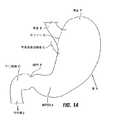
人体の胃S及びそれに関連する特徴の解剖図を図1Aに示す。食道Eは口から胃Sへ食物を送る。zライン即ち胃食道接合Zは、食道の薄い組織と胃壁の厚い組織との間の不規則形状の境界である。胃食道接合領域Gは、食道Eの末端、zライン、及び胃Sの基部を包囲する領域である。 An anatomical view of the human stomach S and associated features is shown in FIG. 1A. The esophagus E sends food from the mouth to the stomach S. The z-line or gastroesophageal junction Z is an irregularly shaped boundary between the thin tissue of the esophagus and the thick tissue of the stomach wall. The gastroesophageal junction region G is a region surrounding the end of the esophagus E, the z line, and the base of the stomach S.
胃Sは、その基端に胃底Fを、その末端に幽門洞Aを含む。幽門洞Aは、小腸の基端領域の十二指腸Dへ付着する幽門Pへ入る。幽門P内にあるのは、十二指腸から胃への食物の還流を防ぐ括約筋である。十二指腸Dの末端に位置する小腸の中間領域は空腸Jである。 The stomach S includes a fundus F at its proximal end and a pyloric sinus A at its distal end. The pyloric sinus A enters the pylorus P attached to the duodenum D in the proximal region of the small intestine. Within the pylorus P is a sphincter that prevents the return of food from the duodenum to the stomach. The middle region of the small intestine located at the end of the duodenum D is the jejunum J.
図1Bは胃壁を形成する組織層を示す。最外層は漿膜層即ち「漿膜」Sであり、胃壁の内層である最内層は粘膜層即ち「粘膜」MUCである。粘膜下組織SM及び多層筋層Mは粘膜と漿膜との間に位置する。 FIG. 1B shows the tissue layer forming the stomach wall. The outermost layer is the serosa layer or “serosa” S, and the innermost layer, the inner layer of the stomach wall, is the mucosa layer or “mucosa” MUC. The submucosa SM and the multilayered muscle layer M are located between the mucosa and the serosa.
様々な形式のインプラントを食道又は胃内に配置可能である。これらは胃食道還流症の治療のために移植された人工弁を含んでいる。胃インプラントにおける他の分野は肥満症抑制のための人工インプラントである。これらは胃の内室に繋止される膨張自在バルーンなどの空間占有デバイスを含んでいる。他の肥満抑制インプラントは米国特許出願第09/940,110号(出願日:2001年8月27日)、米国特許出願第10/118,211006号(出願日:2002年4月8日)、米国仮特許出願第60/379,306号(出願日:2002年5月10日)、米国特許出願第10/345,666号及び第10/345,1104号(出願日:2003年1月16日)に示されて説明されている。これらの出願は本願の譲受人の名義であり、それらの出願の開示事項は本明細書に参照により組み込まれている。これらのデバイスの特定の形態は胃基部における人工ポーチの位置決めに関する。例えば図2Aに示す形式の人工ポーチ2は、図2Bに示すように胃基部内又は胃食道接合領域に配することができる。このポーチは制限体として働き、食道から胃への食物の流れを制限することにより摂取される食物量を抑制する。 Various types of implants can be placed in the esophagus or stomach. These include a prosthetic valve implanted for the treatment of gastroesophageal reflux disease. Another area of gastric implants is artificial implants for obesity control. These include space occupying devices such as inflatable balloons that are anchored to the gastric chamber. Other anti-obesity implants are US patent application Ser. No. 09 / 940,110 (filing date: August 27, 2001), US patent application Ser. No. 10 / 118,211006 (filing date: April 8, 2002), US Provisional Patent Application Nos. 60 / 379,306 (filing date: May 10, 2002), U.S. Patent Applications Nos. 10 / 345,666 and 10 / 345,1104 (filing date: January 16, 2003) Day) and explained. These applications are in the name of the assignee of the present application, and the disclosures of those applications are incorporated herein by reference. A particular form of these devices relates to the positioning of an artificial pouch at the stomach base. For example, an
この種のポーチ2は基部開口4及び小径末端開口6を含み、食道からの咀嚼食物を集める小さな貯蔵器を形成するので、一回に消費できる食物の量を制限する。その小さな容積(容積約2cc乃至300cc程度であるが、好ましくは10から30ccの範囲である)のために、ポーチは一回に消費できる食物量を制限するように機能する。時間が経つにつれて、貯蔵所内の食物は末端開口を通じて胃へ下降する。 This type of
ポーチは、食物で満たされるにつれて膨らんで、上部胃及び下部食道括約筋に対して圧力を加えて、患者に満腹感を感じさせる。他の形式の制限器は上述した従来の出願及び本願に開示されている。 The pouch swells as it is filled with food, applying pressure to the upper stomach and lower esophageal sphincter, causing the patient to feel full. Other types of restrictors are disclosed in the above-mentioned prior applications and in this application.
ポーチ2又は他の制限インプラントは可撓性材料から形成してもよい。このような材料の例は、ポリエステル(例えばDacron(商標)ポリエステル)、ePTFEファブリック(例えばGoreTex商標ファブリックその他)、ポリウレタン(例えばChronoFlex(商標)ポリウレタン、ナイロンファブリック、シリコン、他のポリメリック材料、及び生体内吸収性材料(例えばPLLA、PGA、PCL、ポリ−アミヒドリドその他)を含むが、これらに限定されるものではない。ポーチ2の場合、ポーチの側面を通じて食物の通過を防ぐ材料が最適であるが、これは必須事項ではない。この材料は、可撓性、半可撓性及び/又は非可撓性材料の組成から形成でき、これらはポーチに可撓性の程度が異なる個別の領域を与えて、その様々な場所におけるポーチの膨張を可能にさせるか又は制限させる。例えば、充分に可撓な出口ポートを有するポーチを与えて、大きな食物片が摂取された場合の閉塞を防止するか及び/又はポーチからの食物の出口圧力を調整することが望ましく、一方、ポーチの基端は剛にして膨らみを防ぐようにしてもよい。ポーチの個別の領域におけるポーチの断面厚さを変化させることにより、様々な程度の可撓性をポーチに構築してもよい。その材料は潤滑で生体内適合の化学的不活性材料、例えばパラレインで被覆して基体との摩擦を低減するようにしてもよく、これはデバイス上の食物の付着及び堆積を防止するのに役立つ。 The
制限インプラントは、支持部材によって補強又は支持されるように構成してもよく、例えば柔らかいメッシュ、ケージ構造、リブ、リング等である。支持部材はステンレス鋼、ポリマー、形状記憶材料(例えばニチノール、形状記憶合金、又は形状記憶ポリマー)、或いは材料の厚い領域により形成してもよい。インプラントは自己膨張性に構成して、展開デバイス又はカテーテルから排出される際に、ポーチが径方向に弾けて解放されて膨張状態になるようにしてもよい。 The restriction implant may be configured to be reinforced or supported by a support member, such as a soft mesh, cage structure, rib, ring, and the like. The support member may be formed of stainless steel, polymer, shape memory material (eg, nitinol, shape memory alloy, or shape memory polymer), or a thick region of material. The implant may be configured to be self-expanding so that as it is ejected from the deployment device or catheter, the pouch can be radiated and released to become inflated.
胃/食道におけるポーチ2その他のインプラントは、縫合8a,8b或いは他の手段、例えばクリップ又は適切な接着剤を用いて基端開口4の境界の周りの繋止点にて所定位置に固定される。このインプラントは、縫合8a,8b又は他の繋止手段を受け入れるようにポーチ2上の隆起区画9のような補強区画を含んでもよい。図2Bに示すように、クリップ又は縫合などの繋止手段が用いられ、繋止手段は胃壁を縫合糸8aにより完全に貫通する(「全厚」縫合又はクリップと称する)か、或いは胃壁を縫合糸8bにより部分的に貫通する(「部分厚」縫合又はクリップと称する)。ポーチと組織との間の縫合をなすために有益なことが判明している一つの縫合取り付けデバイスは、ニューヨーク、ビクターのLSI Solutionsから入手可能な“Sew−Right”縫合デバイスである。ポーチは食道組織へ取り付けてもよいのであるが、より好ましくは、Zラインの下に縫合/クリップを施すことにより、胃壁の厚い組織への取り付けを可能とさせる。 The
胃の内側に固定されると、インプラント及びそれに関連する繋止手段は、胃の運動と咀嚼された食物によりポーチに対して加わる力とに起因する相当な力を受ける。このような力は、例えばポーチ2などの制限インプラント、或いは他の形態の胃食道インプラント、例えば胃食道逆流症の治療のために食道内に移植された人工弁、又は空腹調節のための空間占有インプラントに対して働く。時間を経るにつれて、このような力は、繋止点における胃/食道組織の糜爛に起因して胃壁又は食道壁からのインプラントの脱落を引き起こす。従って胃及び/又は食道内に長期間に亘ってインプラントを保持する繋止機構を与えることが好ましい。 When secured inside the stomach, the implant and its associated anchoring means are subject to considerable forces due to stomach movements and forces exerted on the pouch by the chewed food. Such force may be a restriction implant such as
概要
医療インプラントを体腔内に保持するための様々な方法及びデバイスが開示される。一つの態様によれば、一つ以上の襞を形成して、その襞に対して医療デバイスを結合させるか、或いは着座させる。襞を形成する組織層の間にパッチを配置して、組織層の間に形成される組織癒着を補強してもよい。SUMMARY Various methods and devices for holding a medical implant in a body cavity are disclosed. According to one embodiment, one or more folds are formed and a medical device is coupled or seated to the folds. Patches may be placed between the tissue layers forming the fold to reinforce the tissue adhesion formed between the tissue layers.
図面の詳細な説明
添付図面は、胃食道接合領域を含めて、胃又は食道内のインプラントの保持を促進するために個々に或いは互いに組み合わせて使用可能な多数の方法及び部品を示す。DETAILED DESCRIPTION OF THE DRAWINGS The accompanying drawings illustrate a number of methods and components that can be used individually or in combination with each other to facilitate retention of the implant in the stomach or esophagus, including the gastroesophageal junction region.
これらの方法及び部品は(1)組織を整形するか、或いはインプラントの位置において組織とインプラントとの間の物理的結合の有無によらずに組織構造がインプラントの保持を扶助する方式で組織構造を修正し、(2)デバイスを所定位置に繋止し、及び/又は(3)インプラントの周りの力(例えば食物の圧力又は胃の運動からのもたらされる力)の均一分布を促進して、インプラントが組織に接触又は繋止される箇所における組織糜爛のおそれを最小化する。本願は図2Aの制限デバイスに対する代替的実施例についても説明する。 These methods and components are: (1) shaping the tissue structure in a manner that assists in the retention of the implant with or without physical coupling between the tissue and the implant at the location of the implant. Modifying, (2) locking the device in place, and / or (3) facilitating a uniform distribution of forces around the implant (eg, food pressure or force resulting from stomach movements) Minimizes the risk of tissue wrinkles at locations where the tissue contacts or is locked. This application also describes an alternative embodiment for the limiting device of FIG. 2A.
本願の目的のために、用語「制限デバイス」「飽食デバイス」「閉塞デバイス」又は「飽食ポーチ」は、様々な方式のうちの少なくとも一つにより体重減量を意図したデバイス又はポーチを意味するものとして用いられる。これらは以下の事項を含むが、それらに限定されるものではない。即ち食道から胃への食物の通過速度を緩慢にすること、摂取可能な食物量の物理的制限、及び/又は身体の部分(例えば胃、食道、食道括約筋等)に対して圧力を及ぼして患者に満腹感を経験させること、及び/又は空腹感を調節若しくは空腹感に影響する体内のホルモン又は他の物質のレベルに作用し、及び/又は身体に吸収された摂取食物の量に作用することである。本明細書に説明した繋止デバイス及び方法は、本明細書に特に説明したものに限らず、食道、胃食道接合領域、及び胃の他の部分(胃基端、胃底、胃洞等を含む)内に配置可能な様々な形式の飽食インプラントに有益である。 For purposes of this application, the terms “restriction device”, “satiate device”, “occlusion device” or “satiate pouch” shall mean a device or pouch intended for weight loss by at least one of a variety of ways. Used. These include, but are not limited to: I.e. slowing the passage of food from the esophagus to the stomach, physically limiting the amount of food that can be consumed, and / or applying pressure to body parts (eg stomach, esophagus, esophageal sphincter) To experience a feeling of fullness and / or affect levels of hormones or other substances in the body that regulate or affect hunger, and / or affect the amount of food consumed by the body It is. The anchoring devices and methods described herein are not limited to those specifically described herein, but include the esophagus, gastroesophageal junction region and other parts of the stomach (proximal stomach, fundus, gastric sinus, etc.). Useful for various types of satiety implants that can be placed within.
このデバイスは少なくとも一つのキットとして与えられ、本明細書に説明した任意の移植処置及び/又は保持方法に応じた用途についての仕様を更に含んでもよい。選択的に、このようなキットはデバイス及びそれに関連した方法に関して説明した他のシステム部品、及びこれらのデバイス及び方法に関係する他の材料又は品目を更に含んでもよい。例えば、キットは内視鏡又は腹腔鏡ステープル、縫合、及び/又は切除器具、案内ワイア、位置決めマンドレル、処置の実行に必要とされる他のツールを含んでもよい。 The device is provided as at least one kit and may further include specifications for use depending on any of the implantation procedures and / or retention methods described herein. Optionally, such kits may further include other system components described with respect to the devices and associated methods, and other materials or items related to these devices and methods. For example, the kit may include endoscopic or laparoscopic staples, suturing and / or ablation instruments, guide wires, positioning mandrels, and other tools required to perform the procedure.
実施例は飽食デバイスの内容で説明したが、保持の容易化及び/又は力の均一分布の促進について説明した構成要素及び方法は、他の形式のインプラントにも同様に適することに留意されたい。これらのインプラントは、胃内又は胃腸管の他の場所への胃食道還流症治療用人工弁、胃刺激器、薬物を溶離するpHモニタ及び薬物溶出デバイス、生物製剤、細胞を含むが、これらに限定されるものではない。このような薬物溶出デバイスは、レプチン(飽食感を形成するホルモン)、グーレリン(空腹感を形成するホルモン)、オクトレオチド(これはグーレリンレベルを低減し、ひいては空腹感を低減させる)、インシュリン、化学療法薬、施術後の外傷、潰瘍、裂傷等に対する助けとなる天然生物製剤(例えば成長因子、サイトカイン)を溶離するデバイスを含む。他の例においてインプラントは基盤を与えてもよく、この基盤には特定の種類の細胞が粘着して成長し、食道管に対して生物学的活性遺伝子生成物を与える。他の代替例として、インプラントは治療目的で局所的な線源を与えることができる線源のための基盤を与えてもよく、又は診断配位子を固定して食道管を採取し、特定の標準状態又は病的状態の検証をなす基盤を与えてもよく、或いは、カメラ又は他の撮像デバイスを介して食道管を撮像するための繋止点を与えてもよい。 Although the examples have been described in the context of satiety devices, it should be noted that the components and methods described for facilitating retention and / or promoting uniform distribution of force are equally suitable for other types of implants. These implants include an artificial valve for the treatment of gastroesophageal reflux in the stomach or elsewhere in the gastrointestinal tract, a gastric stimulator, a pH monitor and drug eluting device that elutes drugs, biologics, and cells. It is not limited. Such drug-eluting devices include leptin (a hormone that forms satiety), gorelin (a hormone that forms hunger), octreotide (which reduces gorelin levels and hence hunger), insulin, chemicals Includes devices that elute natural biologics (eg, growth factors, cytokines) that help with therapeutic agents, post-surgical trauma, ulcers, lacerations, and the like. In other examples, the implant may provide a foundation on which certain types of cells adhere and grow, providing a biologically active gene product to the esophageal tract. As another alternative, the implant may provide a basis for a source that can provide a local source for therapeutic purposes, or the diagnostic ligand may be fixed and the esophageal tract removed A basis for verification of the standard state or pathological state may be provided, or a locking point for imaging the esophageal duct via a camera or other imaging device may be provided.
本明細書に説明した実施例は、食道管系の外側の身体部分にインプラントを保持するのに広く適用可能であることに留意されたい。従って用語「インプラント」とは、飽食デバイスのみならず、食道、胃食道接合領域、胃、食道管内の他の場所、又は他の中空器官、体内管、及び体腔内にインプラント可能な医療デバイスを意味するものとして用いる。 It should be noted that the embodiments described herein are widely applicable for holding an implant in a body part outside the esophageal tract system. Thus, the term “implant” means not only a satiety device, but also a medical device that can be implanted into the esophagus, gastroesophageal junction region, stomach, elsewhere in the esophageal canal, or other hollow organs, body vessels, and body cavities. Use it as something to do.
整形技術を用いる保持方法
図3乃至図24はインプラント及びインプラント法を示し、これは身体組織の表面を貫いてインプラントを物理的に結合する接合(例えば縫合、ステープル、クリップ等)を用いてインプラントを身体組織へ結合することを最小化するか若しくは大幅に避ける。これらの実施例においては、インプラントの一部分は身体組織の整形により身体内に形成された組織構造により捕捉される。以下の説明から明らかなように、このような組織構造は、デバイスを保持するように胃の内側に狭窄的に形成してもよく、インプラントの移動に対抗して組織の領域の付着及び/又は胃組織における襞の形成により形成されたポケット、トンネル、棚又は他の遮蔽体としてもよい。この組織構造は、食道から胃を通過する内視鏡処置、及び/又は腹腔鏡若しくは外科処置を用いて形成してもよい。Retention Methods Using Orthopedic Techniques FIGS. 3-24 show implants and implant methods that use implants (such as sutures, staples, clips, etc.) that physically bond the implants through the surface of body tissue. Minimize or greatly avoid binding to body tissue. In these embodiments, a portion of the implant is captured by a tissue structure formed within the body by shaping the body tissue. As will be apparent from the description below, such tissue structures may be constricted inside the stomach to hold the device, and adhere to and / or adhere to regions of tissue against implant movement. It may be a pocket, tunnel, shelf or other shield formed by the formation of a fold in stomach tissue. This tissue structure may be formed using endoscopic procedures from the esophagus through the stomach and / or laparoscopes or surgical procedures.
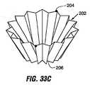
図3は胃組織に形成された襞12により保持される制限インプラント10を示す。この襞は、組織の区画を把持し、この組織を纏めてポケット状の組織構造14を形成するように縫合することにより形成できる。このような構造は、その構造が組織により束縛された内部空間を有し、且つ少なくとも一つの開口が当該内部空間へ延出するという意味で「ポケット状」である。このポケットの内壁は、互いに接触するように置いて、シャツのポケット内の空間が潰れるのと同様な方式で内部空間を潰すようにしてもよい。このポケットは、内部空間の対向する両側が開口しており、器具、或いは医療デバイスの一部がポケットを通過するという意味で「トンネル状」でもある。必要とあれば、このような開口は一つのポケットに二つより多く設けてもよい。他の実施の形態では、ポケットはより中空状又はトンネル状とすることができる。 FIG. 3 shows a
インプラント10は脚部材16を含んでおり、これは襞12のポケット14内に保持される。移植処置の間、脚部材はポケット14へ挿入してもよく、或いは襞12を脚部材16の周りに形成する場合には、その襞の形成の前にインプラントを位置決めしてもよい。 The
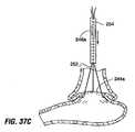
制限インプラント10は制限部品18を含み、これは例えば食道と胃との間又は胃の一領域と胃の他の領域との間の流路の有効断面積を低減させることにより、胃への食物の流れを緩慢にさせる任意の形態としてもよい。例えば制限要素は、図2Aのポーチ2にみられるのと同様なポーチとしてもよく、又は制限リング18a(図3、図4A,図4B参照)又はノッチ付ディスク18b(図4C及び図4D)、或いはメッシュスクリーンとしてもよい。制限要素は、部分的に閉塞させるバルーン18bとしてもよく、これは萎んだ状態において、内視鏡19(図4E及び図4F)を用いる可視化の下にインプラントしてから、空気又はガスなどの膨張媒体源に接続された膨張管21を用いて膨張させることができる。バルーン18bは食物を通す開口を含むように環状等にしてもよく、或いはその外側周りに食物流を可能とするように形状付けてもよい。他の代替例においては、図4A及び図4Bのリング18aのようなリングを設けてもよく、付加的な制限要素(例えばポーチ、ディスク、バルーン等)を移植処置の前又は後にリングへ個別に取り付け可能としてもよい。この種の配置構成の一例を図37Eに示す。この例によれば、施術者は特定の患者に要求される制限量を選択及び変更することができる。
脚部材16は、胃、例えば胃洞、胃底又は胃の他の領域へよく形成された組織ポケットに保持されて、依然としてデバイスの制限オリフィスを胃の基端に位置決めするのに充分な長さである。これに代えて脚部材16は、胃食道接合領域又は胃の他の基端部分における襞により保持されるようにより短くしてもよい。この組織襞を用いてインプラントを保持する概念は、胃の他の領域(及び身体全体)に配置可能なインプラントによく適用できるのであって、胃基端における拘束を与えるインプラントの使用に限定されるものではない。 The
図4Aのインプラント10aは、部材16aの端部における軟性ストップ24のような保持要素を含む。これらの要素はポケットへの通過のために変形して、そのポケットを出ると膨らむ。膨張自在要素も同様に用いることができる。図4Bに示す他の代替例のように、軟性ストップは鉤又はフック24aに置き換えてもよく、これは真っ直ぐにされた向きではポケット14を通じて配置され、この配置に続いて、曲げられた向きへ変形又は調節可能である。 The
ポケットの形成
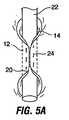
ポケットの向きは、襞及び/又は保持すべきインプラントの向きにより達成される目的に応じて選択できる。図3を再度参照すると、ポケット14はより垂直な向き(即ち胃食道接合領域からほぼ半径方向に離れる)を持つように形成してもよく、これは後続の図面に示すように胃の一部のやや周辺周りに整列するようなより水平なポケットとは対照的である。図5Aを参照すると、ポケット14は胃の内側でマンドレル22の周りの組織の折り曲げ部20を引き出して、この折り曲げ部を縫合24を用いて纏めて付着させることにより形成された襞12を含んでもよい。次いでマンドレルを取り除いて、所定位置にポケット14を残すようにする。その後、図5Bに示すようにインプラント10の脚16をポケット14へ挿入する。時間を経るにつれて、適切に保持された組織の領域は互いに粘着するが、これは身体の生理学的又は生物学的反応、例えば繊維性組織又は瘢痕性組織の形成、新たな組織の成長、或いは対向する組織層の成長、治癒、癒着に起因する。本願において用語「粘着」とは、何らかの生理学的又は生物学的反応(これは上記に列挙したものを含むが、それらに限定されるものではない)の結果としての対向組織層の粘着を意味するように用いるものとする。Pocket Formation The pocket orientation can be selected depending on the purpose achieved by the orientation of the heel and / or the implant to be retained. Referring again to FIG. 3, the
図6Aは腹腔鏡又は開口外科処置のもとに胃の外面へ近づける外科用ステープラー28を用いた襞12の形成を示す。図示のようにステープラー28は、その顎の最遠端部分にステープル30を設けているが、その顎のより基端の部分32にはステープルは存在しない。襞を形成するためには、顎を胃組織の区画上に締め付けて、ステープル30を組織へ貫通させる。図9Bに示すように、顎の基端部分32(図6A)内にある組織の区画は、ステープルで留められていないので、組織ポケット14が形成される。図6Dの上部断面図を参照すると、このような組織ポケット14の幾つかは胃の周りに形成できるので、図3に示すように、制限デバイスの部分(例えば脚部材16)はポケット14内に配置できる。以下に詳細に説明するように、組織襞を形成する組織の結合方式は、胃壁に沿って生じる膨張力F(図6D)に対して襞が耐えるように選択せねばならない。 FIG. 6A shows the formation of a
図7は胃壁の一部分の上部断面図であって、(例えば食道を挿通させる内視鏡法で)垂直襞12を胃の内側から形成して、組織ポケット14を形成できることを示している。これは胃へ経口導入される内視鏡的ステープル、縫合デバイス、又はクリップアプライヤーを用いて実行できる。 FIG. 7 is a top cross-sectional view of a portion of the stomach wall showing that the
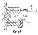
図8A及び図8Bは、図7に示すような組織ポケットを、食道を経て胃へ挿通される内視鏡デバイスを用いて形成する方法を示す。これらの方法は胃壁を通じる外科的又は腹腔鏡処置を利用して実行してもよい。 8A and 8B show a method of forming a tissue pocket as shown in FIG. 7 using an endoscopic device that is inserted through the esophagus into the stomach. These methods may be performed utilizing surgical or laparoscopic procedures through the stomach wall.
これらの方法によれば、内視鏡的把持器36(図8A)、コークスクリュー機構38(図8B)、吸引器40(図8B)又は他のデバイスを食道を経て胃へ挿通し、これを用いて胃壁の内面上の組織の折り曲げ部42を挟む。縫合(又はクリップ、ステープル等)を折り曲げ部42へ挿通させ、折り曲げ部を引き出して互いに接触させて図7に示す形態にする。図8Cに示すように、折り曲げ部42を一緒に結合する前に、各々の折り曲げ部42を通じて縫合又はステープルの列46を加えることが望ましい。 According to these methods, an endoscopic grasper 36 (FIG. 8A), corkscrew mechanism 38 (FIG. 8B), aspirator 40 (FIG. 8B) or other device is inserted through the esophagus into the stomach and used. Thus, the tissue bending portion 42 on the inner surface of the stomach wall is sandwiched. A suture (or clip, staple, etc.) is inserted through the bent portion 42, and the bent portion is pulled out and brought into contact with each other to form the configuration shown in FIG. As shown in FIG. 8C, it is desirable to add a row of sutures or
選択的に、縫合/ステープル等は、牛心膜片、テフロン片、又はポリカーボネイト片などの強化部材のパッチまたはストリップ44(図7)に挿通させて、接触組織層が互いに粘着する時間が経過するまで身体組織内のステープル/縫合の保持を促進するようにしてもよい。代替的に、図26A乃至図30Bに関連して説明した形式の綿撒糸、T形バー等を組織粘着が生じる時間が経過するまで縫合/ステープルを強化するように用いてもよい。 Optionally, a suture / staple or the like is inserted through a patch or strip 44 (FIG. 7) of a reinforcing member such as a bovine pericardium piece, a Teflon piece, or a polycarbonate piece so that time passes for the contact tissue layers to adhere to each other. Up to the retention of staples / sutures in body tissue. Alternatively, pledgets, T-bars, etc. of the type described in connection with FIGS. 26A-30B may be used to reinforce the suture / staple until the time when tissue sticking has elapsed.
時間が経ると、組織表面の間の粘着形態は縫合により接触状態に保持されるので、組織表面の間には、縫合のみの使用により達成されるよりも非常に強い結合状態が形成される。所望とあれば、溶ける縫合糸即ち生体吸収性縫合糸を用いて襞を形成してもよい。 Over time, the cohesive form between the tissue surfaces is held in contact by the suture, so that a much stronger bond is formed between the tissue surfaces than is achieved by using only the suture. If desired, the heel may be formed using a meltable suture, ie, a bioabsorbable suture.
図8A乃至図8Cに示す処置は、胃外面の漿膜組織内層の粘着に部分的に依存する点で特に有益である。漿膜組織層は、互いに適切に保持された際に比較的に強い結合状態を形成するように粘着することが判明している。図8A乃至図8Cの処置は、組織折り曲げ部又はタブ20が互いに粘着した後においても、或る程度の内部胃組織の粘着を進めるので、内側胃組織の対向領域の粘着を最適化するためには、内側組織表面の修正が更に必要なこともあろう。特に、内壁面の良好な粘着は、胃内壁内層組織の粘膜層の一部を除去して、互いに適切に縫合された組織面が漿膜、粘膜下層又は筋層である場合に達成されるものと考えられる。 The procedure shown in FIGS. 8A-8C is particularly beneficial in that it depends in part on the adhesion of the serosal tissue lining on the outer stomach. Serosa tissue layers have been found to adhere to form a relatively strong bond when properly held together. The procedure of FIGS. 8A-8C promotes some degree of internal gastric tissue adhesion even after the tissue folds or
図8Cを参照すると、組織粘着を促進する一つの表面修正方法は、点線で示すように胃の内側の各組織折り曲げ部20の粘膜面の切除、焼灼(RF、レーザー、或いは化学的焼灼)又は剥離を含む。この修正方法は、折り曲げ部が適切に配置されて互いに縫合される前に実行するのが理想的である。切除、焼灼、剥離がなされる深さに依存して、粘膜層の下の粘膜下層、筋層、又は漿膜層が露呈し、図8Dに示すように、各折り曲げ部の対応する剥離/切除部分が適切に配置されて、互いに縫合/ステープリングされる。これは、組織の露呈領域を互いに縫合し、時間が経つにつれて対向面をしっかりと粘着させることを可能にする。この処置の間、施術者は着色剤又は他のマーカーを用いて露呈領域に印を付けることにより、露呈領域が互いに適切に配置させる時を経た際にも組織を容易に識別できるようにすることが有益であろう。 Referring to FIG. 8C, one method of surface modification that promotes tissue adhesion is to remove the mucosal surface of each tissue fold 20 inside the stomach, cauterize (RF, laser, or chemical ablation) or as shown by the dotted lines. Includes exfoliation. This correction method is ideally performed before the folds are properly positioned and stitched together. Depending on the depth at which excision, cauterization, and exfoliation is performed, the submucosa, muscle layer, or serosa layer below the mucosal layer is exposed, and as shown in FIG. Are properly positioned and sutured / stapled together. This allows the exposed areas of tissue to be stitched together and the opposing surfaces to stick firmly over time. During this procedure, the practitioner marks the exposed area with a colorant or other marker so that the tissue can be easily identified even after the exposed areas have been properly positioned relative to each other. Would be beneficial.
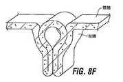
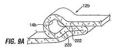
図8Eは、図8A乃至図8Dに関連して説明した方法を用いて形成された襞12a及び組織ポケット14aの斜視図である。図示から明らかなように、襞は長い漿膜接触線220を含む。粘膜又は粘膜下層接触線222(図8Dに示すように組織修正がなされたものとする)は比較的に小さい。漿膜接触線220に沿って形成される粘着は、粘膜又は粘膜下層接触線222に沿って形成される粘着よりも強いと考えられるので、襞は、矢印Xで示される寸法が矢印Yで示される寸法よりも大きくなるように寸法付けることが望ましい。この形態は、胃に対して働く最大の力(図6Dの力F参照)が漿膜粘着により担われることを可能とする。図8Fに示すように、図8Eの襞を延伸させたものを形成して、接触領域の長さを更に延伸させることにより、粘着組織の強度を最適化させてもよい。充分に長い粘着からもたらされる他の形態を図8Gに示す。 FIG. 8E is a perspective view of the
図9Aは漿膜接触220の領域における大きな部分及び粘膜又は粘膜下層接触222の比較的に小さい領域に依存する組織ポケット14bの他の形態を示す。更に、図9Bに示すように、粘着をもたらす接触線は、胃によって及ぼされる主要な力Fに対して「せん断(in shear)」に向き付けられているので、このような力に応答して引き離される傾向を低減できる。これは、力Fに対して接触線が「剥離する(in peel)」ように向き付けられた図6Dのポケット14とは対照的である。 FIG. 9A shows another form of
図9Cは、襞12cを形成する接触線がせん断に向き付けられた組織ポケット14cの他の形態を示す。この形態は、三つの襞部分を利用して非常に長い漿膜接触領域220を形成している。 FIG. 9C shows another form of
図10A,図11D及び図36Aは、形成可能な組織構造の代替形状を示し、ここでは漿膜接触線が剥離状の粘着を形成しているが、粘膜粘着線ではなく漿膜粘着線を利用するという点で図6Dの襞とは異なっている。 FIGS. 10A, 11D and 36A show an alternative form of tissue structure that can be formed, where the serosal contact line forms a peelable adhesive but uses a serosal adhesive line rather than a mucosal adhesive line. This is different from the bag of FIG. 6D.
図10Aを参照すると、襞12dを形成するために、胃内室内の組織を互いに挟み付けて、胃外側上に漿膜層を引き出して互いに接触させることにより、折り曲げられた組織タブ20dを形成している。孔15がタブ20dに形成されており、この孔15の周りにステープラー17又は縫合糸等を配置することにより、漿膜粘着が形成されるまで、組織を纏めて挟み付けた状態に保持する。図10Bに示すように、複数のタブ20dを形成し、制限デバイスの一部(例えば図3に示す複数の脚16)をタブ内の孔15へ通して、インプラントを胃内に固定するようにしてもよい。これに代えて、インプラントは縫合又はクリップを用いてタブ20dから懸架させてもよい。 Referring to FIG. 10A, a folded
他の代替例として、図10Aの襞は、孔20dを廃し、縫合糸又はクリップを用い、この縫合糸又はクリップを組織へ通して組織をインプラントへ結合することにより、組織ポケットを伴わずに用いてもよい。この代替例の変形例は以下に図36A乃至図36Fを関連して説明する。 As another alternative, the scissors of FIG. 10A can be used without a tissue pocket by eliminating the
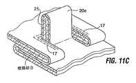
図11Dに示す形式の構造を形成するために、胃内室内の組織を再び挟み付けて、漿膜層を図11Aに示すように接触するように引き出し、折り曲げられたタブ20eを形成する。次に、ステープル17又は縫合糸等を用いて、タブ20eを通るC字状(又は類似の形状)線を規定する。図11Bに示すように、切除21は胃組織の全厚を通じて形成される。切除21は全厚の切除であるので、ステープル17を用いて胃内室を胃の外側から封止する。 To form a structure of the type shown in FIG. 11D, the tissue in the gastric chamber is again squeezed and the serosal layer is pulled into contact as shown in FIG. 11A to form a folded
切除21を形成した後、切除21を取り囲む組織の領域を図11Bにおける矢印で示すように下向きに折り曲げる。タブ20eの残りの部分を図11Dに示すように開口して漿膜ポケット14eを形成し、これは胃の粘膜側(内側)から到達可能である。このポケットの内室を形成する漿膜組織には、それを胃酸から保護する小さなステント状デバイス又は他のライナーを敷いてもよい。時間が経ると、粘膜組織層は、このポケットの漿膜内室を越えて(及び/又はステント或いはライナーを越えて)成長するので、これを胃酸環境から更に保護する。 After forming the
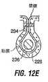
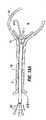
図12A乃至図12Gは、漿膜組織面が適切に保持された際に、形成された強い粘着の利点を有する組織ポケットを形成する他の方法を示す。図12Aを参照すると、ロッド226が胃の外面上に位置しており、縫合糸228がロッド226に取り付けられて胃壁を通過している。この縫合糸228は、内視鏡把持器((図示せず)を用いて内側へ引き出して、図12Cに示す形式の組織の区画230を張る。所望とあれば、ロッド226を省いてもよく、この場合には、一対の縫合糸228aを胃内室から胃壁を通過させて胃内室へ戻し、内視鏡把持器232を用いて内側へ引き出して、点線で示すように組織を張らせる。 FIGS. 12A-12G illustrate another method of forming a tissue pocket having the advantage of strong adhesion formed when the serosal tissue surface is properly held. Referring to FIG. 12A, the
次に図12Dに示すように、張られた組織を横断してステープル又は縫合糸の線234を胃の粘膜側から施すことにより、胃の内面に閉止したポケット236を形成する。(ロッド226を使用しているならば)ロッド226はポケット236に取り囲まれる。ステープリ留め/縫合は、内視鏡ステープラー238aを食道から胃へ通過させるか、或いは外科的ガストロノミー部位を通じて胃へ導入される腹腔鏡ステープラー238bを用いて実行でき、これらは図12Cに示してある。ステープラー/縫合デバイスは、次のような特性を有することが好ましい。即ち、漿膜組織を纏めて充分に封止して、完全な漿膜粘着に先立つ胃の漏洩を防ぐが、ステープリングされた組織の治癒を促進する良好な血液流を保証する縫合/ステープル線234を形成することである。例えば、交換ステープルが既に取り除かれているステープルカートリッジを有するように変更された従来のステープラーは、この目的を達成する。 Next, as shown in FIG. 12D, staples or
図12Cに示すように、縫合/ステープリングに先立ち、張られた組織230の周りにカラー240を配置することにより、壁組織に張力を加えて、縫合又はステープリングを促進してもよい。 As shown in FIG. 12C, prior to suturing / stapling, a
縫合線234は、図12Eに示すように組織の漿膜層を纏めて保持するので、ポケット236が共に保持される。ポケットの端部242を切断し、ポケット216を組織ポケット244へ折り曲げ、これは胃内室へ開口する端部を有する。(ロッド226を用いているならば)ロッド226はポケット244から取り出す。他の実施の形態として、組織は、ポケットを維持する粘着を形成するように共に治癒することが好ましい。
組織ポケット244は漿膜組織で形成されているので、ポケット224にはステント状デバイス246又は他のライナーを敷くことが望ましくは、これらはポケットを補強し、且つ漿膜面を胃酸環境から保護する。 Since the
他の実施の形態では、この処置は、所望のインプラントを胃内に保持するのに必要な数の複数のポケットを形成するように連続される。次いでインプラント(又はインプラントの部分)を胃内に保持するためにポケットへ供給する。一例として、デバイス10(図3)のようなデバイスの脚16をポケットを通じて延伸させてもよい。これに代えて、他の形態のインプラント(例えば、診断又は治療剤又はデバイス、図12GのC字状バー(これにはインプラントやデバイスの占める空間が取り付けられる)を包含するカプセル)をポケット244内に配置してもよい。薬物溶出カプセル又は同様なインプラントは、この方法又は他の方法を用いして形成するポケット内に完全に適合するように寸法付けられる。ポケットにおける開口はカプセルの挿入に続いて閉止して、カプセルにより溶出した薬物がポケットの壁から胃へ通過するようにしてもよい。 In other embodiments, the procedure is continued to form as many pockets as necessary to hold the desired implant in the stomach. The implant (or part of the implant) is then delivered to the pocket for retention in the stomach. As an example, a
第三の代替例として、部材をポケット内に配置して、体重減量に用いられる胃バルーン又は他の空間占有デバイス、或いは治療又は診断デバイスのような他の形式の医療デバイスに繋いでもよい。 As a third alternative, the member may be placed in a pocket and connected to a gastric balloon or other space occupying device used for weight loss, or other types of medical devices such as therapeutic or diagnostic devices.
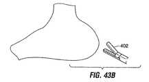
図43A乃至図43Dはインプラント10のようなインプラントを保持するために組織ポケットを形成する他の方法を示す。図43Aを参照すると、先ずインプラント10を所望のインプラント位置へ配置し、関節付マンドレル400などの少なくとも一つの器具を用いて所定位置へ保持して、ポケットを脚16の周りに形成する。これに代えて、各ポケットは、図12Dに関連して説明したガイド226のような一時的ガイドの回りに形成してもよく、この場合、脚16は後にポケットへ通される。 43A-43D illustrate another method of forming a tissue pocket to hold an implant such as
次に、図43Aに示すように切除/ステープリングデバイス402を胃の外面へ進めて胃を把持するのに用いて、二つの対向する胃壁とデバイス10の一つの脚16(又はガイド226)とを切除/ステープリングデバイスの顎の間に捕捉する。好ましくは、切除/ステープリングデバイス402は腹腔鏡処置を用いて導入するが、この処置は切開外科的技法を用いても実行できる。 Next, as shown in FIG. 43A, an ablation /
切除/ステープリングデバイス402を用いて、胃の対抗する両壁を通る切り欠き又は孔404を形成し、図43C及び図43Dに示すように、壁の粘膜面を共にステープリングすることにより、孔404の対向側におけるアタッチメントの行又は列406を形成する。ステープルは、対向する胃壁を互いに結合して脚16(又はガイド226)の周りに組織ポケット408を形成すると共に、胃の内容物の腹膜への漏洩に対して孔404を封止するのにも役立つ。時間が経ると、孔404の内面の四つの切除縁410が治癒して、対向する胃壁の間の強い粘着線を形成する。行/列406は図示のように直線状になるか、或いは他の適切な形態を採り得る。切除孔404に対する一つの代替例として、図10Aに関連して説明した形式の一つ以上の孔を組織を通じて形成し、上述のようにステープル/縫合糸の環状(又は他の代替的形状)配置により包囲してもよい。また、本願の何れかの箇所に説明したようなステープルに代えて、他のアタッチメント機構を用いてもよい。 The ablation /
図43E乃至図43Iに示す第2の連続段階を用いて第2の粘着線を形成してもよい。上述のようにしてポケット408を形成した後、このポケットの両壁上にある漿膜組織領域412を、新たに形成されたトンネル(図43E参照)の周りで部分的又は全体的に被包して、被包姿勢で繋止する。例えば図43Fに示すように、漿膜組織領域412をポケット408の周りで部分的に被包して、この領域412とポケットの外壁との間の漿膜対漿膜接触を形成してもよい。この領域412は、縫合糸、ステープル、クリップ、接着剤又は何らかの適宜な手段を用いてポケットの外壁へ繋止される。最終的には、漿膜層は互いに粘着して第2の封止線を形成して、胃内容物の腹腔内への漏洩に対する保護を与える。 The second adhesive line may be formed using the second continuous stage shown in FIGS. 43E to 43I. After forming the
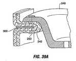
図43Gは、領域412がポケット408の周りを完全に被包して、互いに及び/又はポケットを包囲する組織へ繋止されることを示す。図43Hは、補強及び/又は内部成長促進材料をポケット408を完全に又は部分的に取り囲むように配置することを示す。この材料は合成又は非合成メッシュ、多孔性材料、溝穴付材料、又は他の材料(これを通じて粘着が形成されるか若しくは組織が成長する)としてもよい。例えば、ポリプロピレン、Goretex又はDacron(共に商標)の名称の下に販売される材料、又は組織移植材料(例えばWilson Cook Medical,Incにより販売されるSurgisis材料)を含むが、これらに限定されるものではない。この材料は、生物学的製剤などの組織内成長促進物質により処理してもよい。このような材料を用いるならば、漿膜組織層の間に形成される粘着は、材料の隙間へ及び/又はこの隙間の上を通過し、組織層の間の結合を補強するのに役立つ。本明細書に説明したポケットを形成する他の方法のように、方法の段階は、保持すべきデバイスの各部品(例えば脚16)について繰り返されることが好ましい。図43Iに示すように、ポケット408をずらすことにより、孔404の一側上の切除縁410aを孔の対向側の切除縁410bに隣接させて互いに固定して、図43Iにおける領域414として示す領域における漿膜対漿膜粘着を更に促進させてもよい。 FIG. 43G shows that
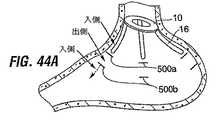
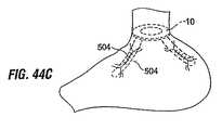
例えばデバイス10の脚16を保持する組織ポケット形成の他の方法を図44A乃至図44Cに示す。先ず、一対の切り込み500a、500bを胃壁を通じて形成する。脚16を最上位部の切り込み500aを胃の外側へ進め、下側の切り込み500bを通じて胃へ再び挿入して、図44Bに示すように、脚16の一部分を胃の外面に対して位置するように残す。脚の自由端は、この脚が定位置から滑り出さないように、図示のように屈曲した形態を含んでもよい。次に、脚の露呈部分502の対向側にある漿膜組織領域504を脚部分502へ折り畳んで、縫合糸又は他の適宜な手段を用いて互いに粘着する。漿膜対漿膜粘着がこれらの組織504の間に形成されて、胃が封止されると共に、脚が捕捉される。 For example, another method of forming a tissue pocket that holds the
組織面修正
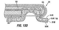
図8C及び図8Dに関連して説明したように、胃内室面が適切に配置されて粘着を誘発する際には、組織面を修正して、粘膜下層、漿膜、筋層組織(粘膜組織ではない)を用いて粘着を形成することが有益であろう。図13A乃至図14Bは、この目的のために胃内室面を変えるための様々な方法を示す。Tissue surface modification As described in connection with FIGS. 8C and 8D, when the gastric chamber surface is properly positioned to induce adhesion, the tissue surface is modified to provide submucosa, serosa, muscle tissue. It would be beneficial to form a stick using (not mucosal tissue). Figures 13A-14B illustrate various methods for changing the gastric chamber surface for this purpose.
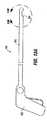
一つの例として、単独のデバイスを用いて、表面組織の領域を修正すると共に、修正された組織表面を接合することができる。図13A及び図13Bは切除及び縫合デバイス48を示し、これは胃内室から組織層を薄く切り、組織の残りの部分へ縫合糸を通す。特に、このデバイスは、組織の隣接表面領域を修正して、修正された表面領域を引き出して、互いに接触させて粘着を促進して組織ポケットを形成することができる。 As one example, a single device can be used to modify regions of surface tissue and to join the modified tissue surfaces. 13A and 13B show an ablation and
図13Aを参照すると、デバイス48はハンドル52から延伸する細長いシャフト50を含む。ハンドル52には、当業者には公知の方法を用いて少なくとも一つの面でシャフト50を関節操作するための手段が設けられている。 Referring to FIG. 13A,
図13Bを参照すると、デバイス48の末端に凹所54が形成されている。縫合糸ルーメン56、針ルーメン58、及び切刃ルーメン60は、シャフト50を通じて延伸して、凹所へ別々に開口している。このデバイスは選択的に吸引源(図示せず)を設けてもよく、これは吸引を加えて組織を凹所54へ引き出すことを可能にする。この目的のために、凹所の内室へ露呈した複数の入口を有する第4のルーメンを設けて、これを吸引源へ接続可能としてもよい。 Referring to FIG. 13B, a
縫合糸62は縫合糸ルーメン56内に配置される。縫合糸62は、その末端に縫合糸留め64を有し、これは凹所54へのルーメン56の開口に隣接して位置している。縫合針66は針ルーメン58内を摺動する。針ルーメン58と縫合糸ルーメン56とは、施術中に針66が針ルーメン58から延出して、凹所内に位置する組織を通じて縫合糸留め64に係合するように向き付けられる。以下に詳述するように、縫合針66の後続の退縮は、縫合糸留め64及び縫合糸の端部を組織を通じて針ルーメン58へ導く。 The
切刃68は切刃ルーメン60内を摺動自在であり、凹所54内に位置する組織から層を薄く切る。ハンドル52(図13A)は、切刃68と針66とを共に伸張及び退縮させるアクチュエータ(図示せず)を含む。 The
次にデバイス48の使用について図13C乃至図13Hを参照して説明する。 Next, the use of the
先ず、デバイス48を内視鏡的視覚化の下に胃へ導入する。このデバイス48を目標の胃組織へ接触するように位置させて、組織を凹所54へ引き出す。このことは、組織面に対して凹所54を押し下げるか、或いは組織を凹所54へ引き出すように構成された吸引源を起動することにより達成できる。既に説明したように、また図13に示すように、組織は複数の組織層を含む。即ち、胃内面にある粘膜MUC、この粘膜MUCの下の粘膜下層SM、筋層M、及び胃外面にある漿膜Sである。凹所54の寸法及び刃68の位置は、一つ又は複数の組織層を刃68で除去するのに適量の組織が凹所54へ引き出されるように選択する。好ましい例では、粘膜MUCを粘膜下層SMが露呈するように除去するか、或いは粘膜と粘膜下層SMとの双方を筋層Mが露呈するように除去する。例示のために、粘膜MUCの除去は図13C乃至図13Fに関連して説明する。 First,
組織が凹所54へ引き出されると、切刃68を凹所54へ進めて(図13D)粘膜MUCを薄く切り取ることにより、粘膜下層の露呈領域E1が残る(図13E)。RFエネルギ源(図示せず)を切刃68へ電気的に接続して、切除中又は切除後に組織を凝固させて、出血を抑制し、且つ組織治癒を促進する。焼灼エネルギを用いるのであれば、接地電極をデバイスの使用中に患者に接触するように配置する。 When the tissue is pulled out to the
次に(或いは切刃68の前進と同時に)、縫合針66を組織を通じて駆動して、縫合糸留め64(図13D)に係合させ、この縫合糸留め64と縫合糸の端部とを組織を通じてデバイス48へ後退させる。この組織は凹所54から開放されて、縫合糸端部をデバイスの基端から回収して、図示のように組織に縫合糸のループを残す。 Next (or simultaneously with advancement of the cutting edge 68), the
次に、隣接する場所で処置を(好ましくはデバイス48と同一のユニットを用いるが、代替的には第2のユニットを用いて)繰り返して、粘膜下層の第2の露呈パッチE2を形成して、図13Fに示すように組織を通じて第2の縫合糸70を配置する。粘膜下層組織の露呈パッチE1及びE2を、例えば縫合糸62,70を引っ張ることにより、互いに接触させて組織ポケット72を形成する(図13G)。縫合糸を互いに繋止させて、露出パッチの間に接触を保持する。 The procedure is then repeated at an adjacent location (preferably using the same unit as
最終的に、露呈した粘膜下層(又は筋層)表面は互いに粘着して、強い組織粘着を形成し、これは胃内に組織ポケットを保持する。図13Gに示すように、胃内室とポケット72の内室との双方は正常な粘膜MUCに囲まれて留まる。 Eventually, the exposed submucosal (or muscle) surfaces adhere to each other to form a strong tissue adhesion, which retains the tissue pocket in the stomach. As shown in FIG. 13G, both the gastric chamber and the
図13Hを参照すると、インプラント10の脚部材16は組織ポケット72内に固定されている。これは後日に実行することにより、組織がインプラントによる負荷を受ける前に組織粘着を生じさせるようにする。組織ポケット72は、着色料又は他のマーカーを用いて、インプラント10を何時固定したかを容易に識別できるようにしてもよい。 Referring to FIG. 13H, the
脚部材16の長さによっては、このようなポケット72は一つか二つのみが脚部材16の保持のために必要となるであろうし、或いは各脚部材を図示のように細長い配列の複数のポケット72により保持できるであろう。 Depending on the length of the
対向組織面の間の組織粘着の最適化を達成するように組織表面を修正するためには、他の技術を使用してもよい。図14Aを参照すると、図13Bの切刃68の実施例は、RFループスネアー(RF loop snare)74に置き換えてもよい。使用中には、ループスネアは、組織が凹所54へ引き出された際に組織がループを通るように向き付けられる。組織が凹所内に位置したならば、スネアー(これはRFエネルギーで印加される)を基端方向に退縮させて、目標の組織層を薄く切り取る。 Other techniques may be used to modify the tissue surface to achieve optimization of tissue adhesion between opposing tissue surfaces. Referring to FIG. 14A, the embodiment of the
他の代替例を図14Bに示し、ここでは切刃は、凹所内に配置されたRF電極板76に置き換えてある。凹所54へ引き出された組織は、電極版76に接触するように引き出されて焼灼される。 Another alternative is shown in FIG. 14B, where the cutting edge is replaced by an
組織ポケット内のインプラントの配置
図15A及び図15Bは、デバイス48で形成された形式のポケットを用いてインプラント10を固定するための一つの方法を示す。図15Aを参照すると、中空案内シース78は、患者の口を経て食道を通る。インプラント10は、各脚16に及び必要とあればインプラント本体18に個々に取り付けられた複数のマンドレル80を用いて、流線型姿勢で案内シースを通過して胃へ至る。これらマンドレル80は、胃内の所望の位置への脚の操作を可能とするように操縦できることが好ましい。インプラント10が胃へ入った後は、インプラントはその拡張姿勢へ拡げることが可能となるか、若しくはその拡張姿勢へ拡がる。内視鏡82を案内シース78を通じて胃へ通す。Placement of the Implant within the Tissue Pocket FIGS. 15A and 15B illustrate one method for securing the
次に腹腔鏡的切開を腹腔へ形成し、トロカール84を切開内に配置して、腹腔を問う業者には公知の処置を用いて吹送する。縫合デバイス48(或いは腹腔鏡ステープラー又はクリップアプライヤーなどの他の形式のデバイス)をトロカール84を介して、且つ内視鏡視覚化を用いて、デバイス脚部材16の周りの襞組織ポケットへ通す。この腹腔鏡的処置を各脚部材16について繰り返す。勿論、切開外科的処置を腹腔鏡的処置の代わりに実行してもよい。侵襲性の少ない処置では、縫合デバイス48は、外科的又は腹腔鏡的切開によるのではなく、食道を通じて胃へ導入してもよい。 A laparoscopic incision is then made in the abdominal cavity and a
既に説明したように、インプラントを導入する前に組織ポケット72を形成することが好ましい。前置形成された組織ポケット72は、図13D乃至図13Gに関連して説明したように、或いは代替的な方法を用いて、襞状にできる。 As already explained, it is preferable to form the
脚16を組織ポケット72へ送る一つの方法を図16A及び図16Bに示す。インプラント10の導入準備において、複数の案内ワイア86の末端を食道を通じて胃へ下降させる。この案内ワイアの本数はインプラント10における脚16の数に整合するように選択する。 One way of delivering the
連接内視鏡的把持器88を食道を通じて胃へ通し、その末端が組織ポケット72の基端から出るまで、組織ポケットの末端へ送り込む。把持器88を案内ワイアの一本に係合させ、この案内ワイアを組織ポケットを介して引っ張ることにより、この案内ワイアの末端をポケットの末端から延出させる。この処置を各案内ワイアについて繰り返す。身体の外ででは、インプラント10の各脚16を一本ずつの案内ワイアの基端へ取り付ける。次いで把持器88を案内ワイア86の末端に係合させて、案内ワイア86の末端102を身体の外へ引き出すことにより、インプラントを食道を通じて胃へ向って牽引する。インプラント10が胃へ到達したら、案内ワイア86の末端を個々に操作して、各脚16を対応する一つの組織ポケット72へ別々に引き込む。 The articulating
組織ポケットを用いるインプラントの繋止について、インプラント10に関して説明したが、他の形式のインプラントについても、一つ又は複数の組織ポケットを用いて保持できることに留意されたい。例えば、薬物溶出カプセルを組織ポケット内に配置してもよく、或いは、薬物溶出デバイスが、組織ポケット内に保持される一つ又は複数の繋止部材に取り付けられたカプセルを含んでもよい。同様な配置構成は、上述した形式の診断又は治療インプラントの他の形態について構成してもよい。 It should be noted that although anchoring an implant using a tissue pocket has been described with respect to the
代替的方法
図17乃至図24、及び図34乃至図36Fは胃壁をインプラントの保持促進のために整形できる代替的な方法を示す。Alternative Methods FIGS. 17-24 and FIGS. 34-36F illustrate an alternative method in which the stomach wall can be shaped to facilitate implant retention.
図17に示す構成は、インプラント又は身体組織の間の縫合或いは他の物理的な取り付けを伴わずに使用できるという点で有益である。しかしながら、この構成は、部分的に厚みのある縫合又は繋止部材(これは壁厚の一部分のみが通過する)、或いは胃食道接合領域、食道、又は胃の壁の全厚に亘って浸通する「全厚」縫合又は繋止部材と共に用いることもできる。 The configuration shown in FIG. 17 is beneficial in that it can be used without suturing or other physical attachment between implants or body tissues. However, this configuration may penetrate a partially thick suture or anchoring member (which only passes a portion of the wall thickness), or the entire thickness of the gastroesophageal junction region, esophagus, or stomach wall. Can also be used with “full thickness” sutures or locking members.
図17を参照すると、胃内に配置可能な要素は、くびれ区画92を有する砂時計形状ライナー90と、ライナー90内に配置可能なポーチ2のようなインプラントとを含む。好ましくは、ライナー90の輪郭は、図示のようにポーチ2の基端部分の輪郭を描いている。このライナー90は、ポーチ2の胃内の上下移動を制限するように充分に剛である。 Referring to FIG. 17, elements that can be placed in the stomach include an hourglass-shaped
リング94を砂時計形状ライナー90のくびれ部分を取り囲む体壁の外表面に配置することにより、身体壁組織をライナー90の砂時計形状に適合させて、図示のように狭窄を形成することにより胃の形を変える。必要とあれば、リング94は、部分的厚縫合又は全厚縫合、鉤、クリップ等を用いて所定位置へ固定してもよい。このリング94は図31Gに関連して以下に説明するようにカラー56と同様な特徴を有してもよい。 By placing the
リング94、ライナー90、及びポーチ2の相対位置は、リングがライナー90を所定位置に保持し、次いでライナーがポーチ2を所定位置に保持するようにしてある。選択的な装着スタッド96をポーチ2へ接続し、部分的厚縫合又は全厚縫合を用いてライナー90を通じて身体壁へ縫合する。この種のスタッドの更なる詳細について、図29A乃至図29Fに関連して説明する。このライナー90は胃の粘膜内層を糜爛から保護し、ライナー90とリング94との双方は、それら自体の表面により引き起こされる組織糜爛を防止/最小化するように、それら自体が充分に柔軟である。 The relative positions of the
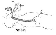
図17の配置構成の選択的な特徴として、ライナー90から末端方向に延出する胃底要素98を含む。この胃底要素98は摂取された食物に晒される胃底の領域を低減させる機能を果たす。時間を経ると、胃底要素の存在は胃内の細胞にグーレリン、空腹の感覚を起すホルモンの生成を減少させる。従って、患者が経験する空腹感の全体的な度合いが低減するので、患者の体重減少をもたらし得る。胃底要素と周囲組織との間の接触は、患者に満腹感を経験させることにより体重減量に付加的に貢献する。 An optional feature of the arrangement of FIG. 17 includes a
図17の構成の他の付加的な特徴は、基端シュート100を含み、これはポーチ2を食道へ延出する。これはリング94の上の領域における胃の拡張を制限するので、患者による過食に対して付加的な制限を与える。 17 includes a
図18に示す他の構成は、図17の構成に類似するが、リング94の上下の組織の間に延在する縫合を加えて、組織に襞104を形成してリングを所定位置に保持している。この襞104は、リングの上下の組織を把持することにより形成されて、組織の把持された束を纏めて縫合することにより形成される(図12A及び図12B並びにそれらに関連する説明を参照)。明らかに、この実施例及び既に説明した実施例において、ステープル又はクリップを縫合の所定位置へ用いることができる。綿撒糸又は繋止部材106は、以下に説明するような形式としてもよく、縫合糸の自由端へ取り付けて、それらが組織を通じて摺動することを防止してもよい。時間が経ると、漿膜及び/又は粘膜組織層は、符合108で示す領域で襞が共に粘着する結果として、互いに接触するので、襞の強度が増大する。上述した形式の組織の薄い切除、焼灼、剥離等を付加的に用いて、最適な組織粘着を保証するようにしてもよい。この実施例は、リング94を省くことにより、或いは単純に襞を用いて胃内に砂時計形状ライナー90及びポーチ2を保持する狭細部分を形成することにより変更してもよい。 The other configuration shown in FIG. 18 is similar to the configuration of FIG. 17 except that a suture extending between the tissues above and below the
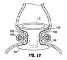
図19は、図18の構成の変形例を示し、ここでは全ての要素を内視鏡的に移植することにより、腹腔鏡的又は外科的段階についての必要性をなくしている。図19の実施例において、リング94を胃内に保持して、図示のように砂時計形状ライナー90及びポーチ2を取り囲む。襞104は胃の中から施される縫合糸(又はクリップ、ステープル等)を用いて形成し、図示のようにリング94を保持する。図18及び図19の実施例においては生体吸収性縫合糸を用いてもよく、この場合、襞を横断して生じる粘着が生じたならば、この縫合糸は身体により吸収されて、身体組織のみにより補足されたリング94が残る。図17乃至図19の構成の各々において、リング94は胃の機能若しくは摂食の挙動に影響するように寸法付けられているが、望ましくは、リング94はそのような影響を持たないように寸法付けることにより、ポーチ2が施術者により取り除かれた際には、リング94が患者の通常の摂食に干渉することなく所定位置に残るようにする。 FIG. 19 shows a variation of the configuration of FIG. 18, where all elements are endoscopically implanted, eliminating the need for a laparoscopic or surgical stage. In the embodiment of FIG. 19, a
図20Aは胃を見降して見た上部斜視図である。この図はリング94の保持に用いられた襞104を示す。複数の襞104は、図示のようにリング94の周囲に互いに離隔して配置できる。図20Bは、縫合糸は縫合線102aで示すように組織の内粘膜層のみに挿通してもよく、或いは縫合線102bで示すように内粘膜及び外部漿膜層に挿通させてもよいことを示している。 FIG. 20A is a top perspective view looking down on the stomach. This figure shows the
図18及び図19に関連して説明したように、リング94は制限デバイス及び/又は関連する構成要素(例えばライナー90)を胃内の移動に抗して保持する目的で胃を「形付ける」ために用いられる。図20Cに示す他の例のように、リング94aはよりディスク状にして、襞組織のみならず、一体的又は取り外し自在な制限オリフィス114を受け入れる窓110を含めるようにしてもよい。ングの外径は、この外径と周囲組織との間の大量の食物通過を充分に防止できるように、周囲組織に対して封止することが好ましい。 As described in connection with FIGS. 18 and 19, the
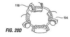
このリング94は、縫合糸、クリップ等を用いてインプランを取り付けることができる繋止部材としての役割もなせる。図20Dに示す他の代替例においては、バー116(又はフック、個々のリング、フック、ボタン、バー等)を組織襞104を用いて支持して、その処置と同一又は後続の処置の間に制限デバイスをそれに取り付けてもよい。これらの各実施例では、インプラントは主として組織襞により支持されているので、インプラントを組織へ接合するための縫合糸又はクリップに対する依存度は最小化若しくは全く無くすことができる。これは即ちインプラントを胃内の所定位置へ保持するのに要する時間を削減できるということである。 The
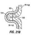
図21A及び図21Bは、襞104は、リング、バー又は他の構成要素を伴うことなく、組織に折り曲げ部を形成して、この折り曲げ部へ縫合糸を通すことにより単純に形成してもよいことを示している。綿撒糸118は、組織から滑り出すことがないように、縫合糸102の端部へ接続してもよい。例えば図18及び図19に示したのと同様な構成により、襞104は、図示の如く胃がライナー90を支持するように胃を「形付ける」ために用いられる。 21A and 21B, the
図22A乃至図24は付加的な構成を示し、ここではインプラントの保持を促進するためにリング又はバンドが用いられる。図22Aの配置構成では、リング94又は拘束バンドをインプラント2aの上下に配置して、胃内のデバイスの基端及び末端方向移動を防止する「止め部」を与えている。インプラント2bの下にリング94のみを用いる同様な構成を図22Bに示す。第3の代替例として、リング94は省いて、その代わりに襞をインプラントの上下(又は下方のみ)で組織に形成して、インプラントの移動を防ぐようにしてもよい。 Figures 22A-24 show additional configurations, where a ring or band is used to facilitate retention of the implant. In the arrangement of FIG. 22A, rings 94 or restraining bands are placed above and below the
図23においては、リング94又はバンドを再びインプラントの下に配置して、インプラントの末端方向移動に対する停止部を形成している。この構成におけるインプラント2cは、リング94上の領域で自由に浮遊する膨張自在若しくは自己膨張型バルーン120の形態を採ってもよい。このバルーン120は胃食道接合領域の大きな割合を占めているので、矢印で示すように食物が通過できるのは外バルーンと周囲身体組織との間の空間のみとすることにより、摂取される食物を制限している。 In FIG. 23, the
図24は図22Bの実施例の他の変形例を示し、ここではリング94が複数の磁性要素を含み、これら磁性要素はインプラント2dの基端にある限りは同一の極性を有する。従って、インプラント2dとリング94との間の斥力はインプラント2dの末端移動を防止する。 FIG. 24 shows another variation of the embodiment of FIG. 22B, where the
図25は、インプラントデバイスを後刻に取り付けることができるフレームワークを胃内に形成するように意図された構成要素の配置を示す。その構成要素は、胃の内壁の周囲に配置可能なメッシュバンド122を含んでいる。内側綿撒糸124はメッシュバンド122の内壁に沿って離間されている。外側綿撒糸126は胃の外壁に沿って離間されている。綿撒糸124,126は縫合糸128によりメッシュバンドへ接続されている。時間が経ると、メッシュバンドは壁組織へ移動する。外側綿撒糸126はメッシュバンドが壁組織を通じて完全に移動することを防止し、一方、内側綿撒糸124は、メッシュバンドが内側へ移動して胃内室の壁組織から離れることを防止する。最終的に、メッシュバンドは壁組織内に包み込まれて丈夫な構造体を形成し、ここにはポーチ2などのインプラントを縫合糸、クリップ又は他のデバイスを用いて取り付けることができる。 FIG. 25 shows the arrangement of components intended to form a framework in the stomach where the implant device can be attached at a later time. The component includes a
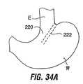
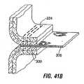
図34A及び図35Aは、胃壁組織を整形し、この整形組織に対してインプラントを着座させる実施例を示す。図34Aに示すように、胃壁を整形して、食道Eから胃Sへ延伸するトンネル220を形成してもよい。このトンネル220は、線222に沿って組織を縫合/ステープリングすることにより内視鏡的又は外科的に形成できる。図34Aに示すように、制限デバイス224は、整形壁組織から形成された組織トンネル220内に配置可能な膨張自在ステント状構造を含んでもよい。 34A and 35A show an embodiment in which stomach wall tissue is shaped and an implant is seated against the shaped tissue. As shown in FIG. 34A, the stomach wall may be shaped to form a
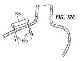
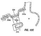
図35Aを参照すると、代替的な整形方法は、胃へ延伸してインプラントを着座させることができる場所を形成するように一つ以上の縫合/ステープル線226を形成することを含む。例えば、制限ポーチ228又は閉塞胃バルーン230をその形成された場所に着座させることにより、整形壁組織がインプラントの腸管食道管への下降を防止する。図34A及び図35Aの実施例において、縫合/ステープル線に沿う組織面は最終的には互いに粘着する。所望とあれば、この縫合/ステープル線の向き付けは、整形組織が、患者の摂食を減らすためのインプラントを支持するプラットホームを与え、インプラントを取り除けば、整形組織に起因する制限を経験することなく人間が摂食できるように選択する。 Referring to FIG. 35A, an alternative shaping method includes forming one or more suture /
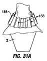
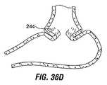
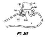
図36A乃至図36Fは胃壁をインプラントの保持のために整形する他の実施例を示す。この方法によれば、組織の周方向隆起を胃内壁の周辺、例えば胃食道接合領域に形成して、この周方向隆起をインプラントの保持に用いてもよい。図36Bを参照すると、漿膜襞は、内視鏡的把持器240、フック、叉状器具、又は同様なデバイスを用いて胃内室の領域を係合させることにより形成される。係合した壁領域を内側へ引っ張ることにより、外側漿膜組織の区画が引き出されて互いに接触して漿膜対漿膜襞242(図36D)を形成する。内視鏡器具により係合された襞によれば、縫合糸243、ステープラー又は他のファスナーを図36Bに示すように襞242に挿通して、襞を保持する。複数の襞242を胃の内周に形成することにより、胃壁を包囲する襞組織の周方向隆起244(図36E)を形成する。時間が経ると、対向漿膜層は粘着を形成する。次いで制限インプラント246を図36Fに示すように隆起244の近傍で胃内に配置する。 Figures 36A-36F show another embodiment of shaping the stomach wall for retention of the implant. According to this method, a circumferential bulge of tissue may be formed around the stomach inner wall, for example, the gastroesophageal junction region, and this circumferential bulge may be used to hold the implant. Referring to FIG. 36B, a serosal fistula is formed by engaging a region of the gastric chamber using an
一つの実施形態によれば周方向隆起は物理的遮蔽体として働き、これは、図22Bにおけるリング94により整形された壁で移動を防止するのと同様な方式で、インプラントの胃基部からの移動を防止する。これに代えてインプラントは、図36Fに示すように縫合糸248、ステープル又はクリップを用いて隆起244へ物理的に接合してもよい。これは次のように実行できる。即ち、内視鏡的器具を用いて隆起244を把持して、隆起244を食道の方向へ引き出し、インプラント246を隆起244と接触するように進めつつ、隆起を内視鏡的器具により保持すると共に、縫合糸/ステープル等をインプラント及び隆起244に挿通させる。本願の何れかの箇所で説明したように、広い表面領域に亘って力を分散させる目的で、綿撒糸250を図示のように用いてもよい。 According to one embodiment, the circumferential ridge acts as a physical shield, which is similar to preventing movement at the wall shaped by the
インプラント246の取り付けは、周方向隆起を形成するのと同一の処置中に実行してもよく、或いは、後日に、即ち隆起がインプラントにより及ぼされる応力を受ける前に粘着を形成させてから実行してもよい。 The attachment of the
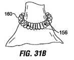
図37A乃至図37Dは、周方向隆起を形成する壁組織の漿膜対漿膜襞を用いると共に、この隆起へインプラントを固定するための僅かに変形された方法を示す。図37A及び図37Bを参照すると、組織は、又状部材241を含む内視鏡的器具240aを用いて襞状にされている。襞を形成するためには、叉状部材241を用いて胃壁組織を基端方向へ引っ張りながら、縫合針243又は他の締結器具を末端方向へ進めて、縫合糸、t字状バー、リベット又は他の締結部材を図37Bに示す如く襞組織へ下向きに駆り出す。力を消散させる要素(例えば綿撒糸)を組織面に対して力を消散させるように用いてもよい。 FIGS. 37A-37D show a slightly modified method for securing the implant to the ridge, using a serosa-to-serosa fold of wall tissue forming a circumferential ridge. Referring to FIGS. 37A and 37B, the tissue has been crouched with an
図37Cを参照すると、このような襞を壁の周辺に幾つか(例えば2乃至4)形成して周方向隆起244a(図37C)を形成している。 Referring to FIG. 37C, several such ridges (eg, 2-4) are formed around the wall to form a circumferential ridge 244a (FIG. 37C).
インプラントの導入は襞の形成の直後に実行してもよく、或いは対向する組織の上述のような粘着後の後日に実行してもよい。インプラントを導入する一つの方法においては、フック状末端を有する複数のワイア252をシース254に挿通させて、周方向隆起244aを引っ掛けるために用いる。複数の小孔(図示せず)を有するインプラント246aは、その小孔の各々を対応する一本のワイア252に嵌めこむことにより、これらワイア上を滑動する。このインプラント246aは圧縮されてシース254へ通されて、このシースを通じて進んで隆起244aに接触し、その間にはワイア252上の張力を保持する。このインプラント246aは、図36Fに関連して説明したように縫合糸、t字状バー叉は他の締結部材を用いて隆起244aへ物理的に接続してもよい。この段階はワイア252上に張力を連続的に加えることにより実行してもよい。図37Dに示すように、かくしてインプラント246aの一部は隆起に対して図37に示すように着座して置かれる。 The introduction of the implant may be performed immediately after the formation of the plication or may be performed at a later date after the adhesion of the opposing tissue as described above. In one method of introducing the implant, a plurality of
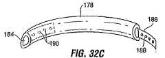
様々な形式のインプラントをこの方法を用いて本願で説明した他の方法のように保持することができるが、図37Dに示すインプラント246aは、図4Aのインプラント10a上に見られるリング18aと同様なリング247を用いている。リングを利用する他の実施例のように、リングはそれ自体で制限デバイスとして働くが、制限デバイスをリングと組み合わせて用いてもよい。例えば、制限デバイスはリング247に対して、取り付けてもよく、懸架させてもよく、着座させてもよく、或いは挿入させてもよい。 Various types of implants can be retained using this method as in other methods described herein, but the
リング247は、ポーチ2に関連して上述した任意の材料から形成してもよく、これはシリコン、ポリウレタン、叉は様々な種類のポリマーの一つを含む。環状バンドからなる補強要素をリング247を通じて延在させてもよく、これはステンレス鋼、ポリマー、形状記憶材料(例えばニチノール、形状記憶合金、叉は形状記憶ポリマー)からなる。このリングは自己膨張性に構成して、展開シースから排出されると、径方向にばね状に開いて拡張状態になるようにしてもよい。これに代えて、このリングは膨張媒体、例えばガス、液体(例えば食塩水)を用いるか、光化学的又は熱可塑性ポリマーを用いて膨張自在としてもよい。他の代替例として、リングは、耐用寿命を過ぎると体内で分解又は腐蝕する材料から形成してもよい。
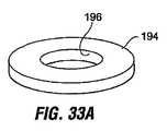
このリング247は図37Eに示すように環状溝258を有するエプロン256を含んでもよい。リングについては様々な材料を用いてもよく、これはPET、ナイロン、或いは本明細書で説明した他の材料のうちの任意の材料を含む。上述したポーチ2と同様な特性を有する制限挿入体260は図示のようにリング247へ挿入可能である。制限挿入体260は制限開口を有し、これは挿入体を通じて胃へ通過する食物の速度を緩慢にするように寸法付けられている。制限挿入体を選択することができるので、施術者には、特定の患者に対してどの程度の制限を用いるかについての選択が与えられる。 The
挿入体260はリム262を含み、これは溝258にスナップ係合してリング及び挿入体を係合させる。図37Fは胃へ向って食道を見降ろした図であって、襞244に対して配置されたインプラント246aを示す。図37Gは同様な図であって、挿入体260がインプラント246aへ取り付けられた後のインプラント246aを示す。
この形式のインプラントを用いる一つの方法においては、施術者がリング247をインプラントした後、患者がインプラントの存在になじむ数日が経過するまで、挿入体260の配置を遅らせてもよい。後に、挿入体260を内視鏡的に食道を通じて胃へ下降させて、所定位置にスナップ係合させることができる。後日、施術者は挿入体260を取り除いて、これを患者の必要性に応じて、より制限的なもの(即ち、より小さな出口オリフィスを有するもの)、或いは制限が少ない挿入体(即ち大きな出口オリフィスを有するもの)に交換することを選択できる。所望とあれば挿入体は、耐用寿命が経過した後に分解又は腐蝕する材料から形成することにより、この挿入体を取り除く必要性を無くしてもよい。 In one method using this type of implant, the placement of the
外部補強
本明細書に説明した幾つかの構成要素は外部補強デバイスとして働く。図2Bについて説明したように、ポーチ2のようなインプラントは、全厚縫合糸8aをポーチ2から隣接する胃組織を挿通させてポーチに戻すことにより、所定位置に縫合又はクリップ留めできる。しかしながら、或る患者には、壁の外面に位置する外部補強デバイスに縫合糸8aを挿通させることにより、縫合糸を「補強」することが望ましいこともあろう。このような形式の外部補強デバイスの幾つかついては上述した。External reinforcement Several components described herein serve as external reinforcement devices. As described with respect to FIG. 2B, an implant such as
外部補強デバイスの例は、綿撒糸130(図26A)、又はt字状バー132(図26B)を含み、その各々は、広い表面領域に亘って縫合糸に対して及ぼされる力を分散させる。綿撒糸又はt字状バーは、全く大きくてもよく(例えば10乃至30mm径)、或いは非常に小さくてもよく(例えば1乃至2mm径)、これは特定の用途に応じて定められる。綿撒糸又はt字状バーに適する材料は、シリコン、フェルト、及び/又はポーチを構成するのに用いるために上記に列挙した材料を含む。Tバーは縫合糸端部に圧接された金属バーから形成してもよい。 Examples of external reinforcement devices include pledgets 130 (FIG. 26A) or t-shaped bars 132 (FIG. 26B), each of which distributes the force exerted on the suture over a large surface area. . The pledget or t-bar may be quite large (eg 10-30 mm diameter) or very small (eg 1-2 mm diameter), depending on the particular application. Suitable materials for pledgets or t-shaped bars include those listed above for use in constructing silicon, felt, and / or pouches. The T-bar may be formed from a metal bar pressed against the suture end.
綿撒糸130の移植処置の間、ポーチ2(図2)のようなインプラントを内視鏡的に胃へ導入しつつ、綿撒糸を腹腔鏡的又は外科的処置により胃の外面に接触するように配置してもよい。縫合糸は胃内から胃壁を挿通させ、綿撒糸を挿通させて、胃の内室へ戻す。所望とあれば、これは二つの手順で実行してもよい。例えば第1の腹腔鏡的処置では綿撒糸を腹腔鏡的に胃の外壁上に縫い付け、第2の内視鏡的処置ではインプラントを食道を通じて胃へ挿通させて、ここで縫合糸をインプラント、胃壁、及び綿撒糸の間へ挿通する。 During implantation of the
tバーの移植処置の間、tバーが取り付けられている縫合糸の端部を内視鏡的処置により胃の外壁に隣接して位置させて、その自由端を胃壁及び内側に位置するインプラント壁を通じて縫合する。 During the t-bar implantation procedure, the end of the suture to which the t-bar is attached is positioned endoscopically adjacent the outer wall of the stomach and the free end is located on the stomach wall and the implant wall Suture through.
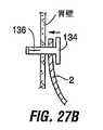
図27Aは代替的な外部補強デバイスを示し、これは「モリ ボルト(moly bolt)」型ファスナー134の形態を採り、このファスナー134は内視鏡的処置により食道を通じて胃へ導入できる。図27Bを参照すると、移植処置の間、インプラント(例えばポーチ2)を胃に対して位置させ、ファスナー134をインプラントの内室からインプラント壁を通じて胃壁に挿通させる。各ファスナー134は、その末端部分136に取り付けられた内部ワイア又は紐(図示せず)を含む。ファスナー134の末端部分136は、それらのワイア又は紐を引っ張ることにより、図27Cに示す姿勢へ拡張することにより、ファスナー134を所定位置へ繋止する。 FIG. 27A shows an alternative external reinforcement device, which takes the form of a “moly bolt”
外部補強デバイスの他の形式を図28A乃至図28Cに示す。図28Aの実施例において、膨張自在バルーン138は胃内室からインプラント及び胃壁を(モリ ボルト型ファスナーについて図27Bに示したのと同様な方式で)挿通してから膨らんで、この膨張したバルーンが胃の内面に留まる。 Another form of external reinforcement device is shown in FIGS. 28A-28C. In the embodiment of FIG. 28A, the
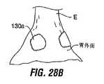
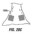
図28B及び図28Cは図26Aに関して説明した綿撒糸に対する代替例を示す。図26Aの綿撒糸のように、図28B及び図28Cの綿撒糸は胃の外壁上に位置し、縫合糸は綿撒糸を通じてインプラントを胃壁に取り付ける。図28Bに示すように、綿撒糸130aには粗い面を持たせて、それらが胃壁の縫合開口を通じて滑動することを防いでもよい。図28Cは、綿撒糸130bをメッシュ、又は細胞内成長を促進することが知られる他の材料から形成することにより、時間が経ると胃壁組織が綿撒糸へ成長して繋止を増強することを示している。 28B and 28C show an alternative to the pledget described with respect to FIG. 26A. Like the pledget of FIG. 26A, the pledget of FIGS. 28B and 28C is located on the outer wall of the stomach, and the suture attaches the implant to the stomach wall through the pledget. As shown in FIG. 28B, the
綿撒糸130に対する他の代替例として、胃の外面上にゲル滴を射出することにより、ここで綿撒糸を形成してもよく、そのゲルは組織面上で凝固する形式である。このゲルは、胃壁に胃の外側から進入する内視鏡的処置により導入してもよく、或いは、胃内室から胃壁を挿通する針を用いてゲルを射出する内視鏡的処置により供給してもよい。ゲルが綿撒糸に硬化したならば、胃壁を挿通する縫合糸、クリップ等を用いて、インプラントを硬化ゲル綿撒糸へ繋止できる。他の代替例として、ゲルを胃壁組織の漿膜と粘膜層との間に射出して、胃壁内にゲル綿撒糸を形成してもよい。 As another alternative to
勿論、上述の外部補強デバイスは、胃内室に配置されたインプラントに対して何らかの方法で接続せねばならない。図29Aは胃内のインプラントへ取り付け得る「スタッド」型ファスナー96を示しており、これは外部補強デバイス(図29Aには図示しない)にも接続される。ファスナー96は、ピン144を有する第1のボタン142と、そのピン144を受け入れる孔を有する第2のボタン146とを含む。図29Bに示すように、ピン144をインプラント(例えばポーチ2)の壁に挿通して、一方のボタン142をインプラントの外面におき、他方のボタン146をポーチの外面におく。次いでファスナー96を外部補強デバイス、例えば図示のように胃の外壁上に位置する綿撒糸130などに接続する。 Of course, the external reinforcing device described above must be connected in some way to the implant placed in the gastric chamber. FIG. 29A shows a “stud” -
図29B乃至図31Fに示すように、ファスナー96を綿撒糸130へ接続するのに様々なデバイスを用いてもよい。インプラントは図29Bに示すのみであるが、図29C乃至図29Fにおいても、当然にインプラントを(例えば図29Bに示す方式で)ファスナーへ取り付けることに留意されたい。 Various devices may be used to connect the
図29Bを参照すると、縫合糸148は胃壁を通じて縫い付けて、適宜な手段を用いてファスナー96と綿撒糸130との両方へ取り付けてもよい。例えば、縫合糸148をファスナー96へ固定するためには、縫合糸をピン144へ結ぶか、或いはボタン142における開口を通じてピン144における孔へ糸通しして、その中に縫合糸を固定するようにピン144を圧接してもよい。この目的のために様々な形式の縫合糸を使用でき、これは例えばモノフィラメント、組み紐縫合糸、コットン、シルク又は生体吸収性縫合糸である。ファスナー96と綿撒糸130との間の縫合糸の長さ部分には、高張力をかけてもよく、張力を緩くしてもよい。図29Cを参照すると、縫合糸に張力を保つことが望ましいならば、綿撒糸130とファスナー96とは同一の極性に磁化し、矢印で示されるような互いに相手に向かう移動に対して抗するようにすることにより、縫合糸の張力が保持される。代替的に、図29Dに示すように、綿撒糸130とファスナー96とを反対極性に磁化して、これらの間の磁力が綿撒糸、インプラント及びファスナーを胃組織に対して共に保持するようにしてもよい。この実施例は、綿撒糸130とファスナー96との間に延在する剛性ポスト(例えばステンレス鋼、ニチノール、プラスチック)を利用して、組織を綿撒糸130とファスナー96との間の圧縮から保護できる。他の代替例として、磁化の使用を伴うことなく、剛性ポスト150は綿撒糸130とファスナー96との間の接続を与え得る。図29E及び図29Fに示すように、綿撒糸138とファスナー96との間の物理的な接続体は、組織内成長を促進する材料、例えばニチノール、ステンレス鋼、ポリマー、又は生体吸収材料から形成されたチェーン152a又はメッシュ152bから形成してもよい。 Referring to FIG. 29B,
図30Aを参照すると、外部補強部材は代替的に自己均衡繋止部材により与えてもよい。これは、胃壁を通じて延在する縫合糸148により接続された一対のバルーン綿撒糸154a,154bの形態を採ってもよく、その一方のバルーン154aを胃内に、且つ他方のバルーン154bを胃の外側に配置する。縫合糸は好ましくは各バルーンの内室を通じて延在させ、隣接する胃壁から最も遠い点でバルーンに取り付ける。インプラント(図示せず)は胃内に配置したバルーン154aに隣接する縫合糸に接続されている。図30Bに示されるように、一対のバルーンの寸法付けは、力が一方のバルーン154aを胃壁から引き離す方向に引く際(例えばインプラントが食物の圧力に応じて内側に引っ張る際)に、他方のバルーンが圧縮されて壁に対して平たくされることにより、有効綿撒糸寸法を増大させて、力が広い領域に亘って分散させるようにする。バルーン綿撒糸は、他の弾性構造体、例えば3次元メッシュ、ステント状フレーム構造体、変形可能エラストマー、又は力を受けたときに変形するが、その力の解放に伴い初期形状を取り戻す他の構造体に置き換えてもよい。 Referring to FIG. 30A, the external reinforcing member may alternatively be provided by a self-balancing locking member. This may take the form of a pair of
カラー
外部補強デバイスの他の形態は胃の外面を取り囲む外部カラーである。図31乃至図31Iは様々なカラー形態を示す。これらの構成の幾つかは、インプラントを綿撒糸型デバイスに接続するために図29B乃至図29Fに示したものを含めて、縫合糸又は他の接続方法を用いてインプラントを物理的に接続することを意図している。これらの接続は、図29Aのスタッドファスナーの有無によらずになせる。インプラントへ接続されると、カラーは綿撒糸130のような働きをなして、インプラントの周りの力の均一な分散を促進する。このカラーと綿撒糸とは、カラーが胃外壁を取り囲み、且つカラーの外面上の綿撒糸が、カラー及び胃壁を挿通する縫合糸を用いてデバイスへ接続されるように組み合わせてもよい。この形態では、カラーが力の分散に役立ち、且つ綿撒糸による胃壁の糜爛を防止する。Color Another form of external reinforcement device is an external collar that surrounds the outer surface of the stomach. 31 to 31I show various color forms. Some of these configurations physically connect the implant using sutures or other connection methods, including those shown in FIGS. 29B-29F, to connect the implant to a pledget type device. Is intended. These connections can be made with or without the stud fastener of FIG. 29A. When connected to the implant, the collar acts like a
他の形態については、カラーは、インプラントへは物理的に接続されないが、デバイスの移動を規制するように配置することも可能である。 For other forms, the collar is not physically connected to the implant, but can be arranged to restrict the movement of the device.
図31A乃至図31Fの実施例は、繋止点156へ繋止されたインプラントデバイスを持つように設計されている。このカラーは、任意の一つの繋止点に大きな力を構築するのではなく、より均一に力を分散させるように可撓になるように意図されている。図31Aの実施例において、カラー158の可撓性は、そのブリーツ付構造からもたらされる。胃の中のインプラント2は、カラーに対して符号158で示される位置で繋止点156へ取り付けられる。図31Bのカラー160はコイルスプリングから形成されている。これらの実施例の両方においては、カラーの可撓性は、繋止点156を胃と共に移動させることを可能とするのであって、そのような胃の移動が生じる際に繋止点に力を構築するものではない。 The embodiment of FIGS. 31A through 31F is designed to have an implant device locked to a
同様な特性は図31C乃至図31Eの実施例に見出せる。図31Cの実施例において、カラー162はステンレス鋼、ポリマー、又は多方向に可撓性を有するニチノールメッシュから形成される。図31Eのカラー164は、その薄い可撓性ポリマーシートの使用に起因して、多方向に伸縮させる能力もある。図31Fの実施例において、カラー166は弾性部材170に取り付けられた複数の個別綿撒糸168を含む。図31Dは、入れ子式要素174a、174bから形成された膨張自在カラー172を示す。スプリング部材176を要素174aに接続して、カラーを膨張させて胃へ接触させる。 Similar characteristics can be found in the embodiments of FIGS. 31C-31E. In the embodiment of FIG. 31C, the
図31G、図31H及び図31Iを参照すると、カラーは単純な円形又は長円形状リングとすることができる。これは図31Gのカラー178のような環状、或いは図31Hのカラー180のように胃の外壁のテーパー形状に整合するテーパー形状を持たせてもよい。このカラーは剛でも可撓でもよい。代替的に、図31Iを参照すると、カラー182は可撓であるが、カラーの剛性を増大するように起動し得る張力ケーブルを含んでいる。これらの実施例によれば、インプラントへ取り付けられた縫合糸を胃壁を通じて縫い付けてカラーへ取り付けるか、或いは、カラーをインプラントから物理的に離隔して留めるが、図17に関連して詳述したようにインプラントの位置を保持するように働かせるようにしてもよい。 Referring to FIGS. 31G, 31H, and 31I, the collar can be a simple circular or oval ring. This may have an annular shape, such as
図32Aは胃外壁を包囲するカラー178の正面断面図を示す。図示のように、カラー178には組織の損傷を最小化するようにD字状断面を持たせてもよい。 FIG. 32A shows a front cross-sectional view of a
カラーは胃の周りを被包するように意図されているので、その設計は、細長い形態で胃洞へ導入してから、胃の周りのループを形成するように取り付けられた自由端を持たせるようにせねばならない。図32Bに示すように、カラー178は一端にスロット184を、反対側端にタブ186を含んでもよい。タブ186はカラーをループ状に形成するようにスロット内で係合可能である。タブ186上に隆起したボタン188はスロット内の凹所190にスナップ嵌合して、カラーを閉止ループに係止する。カラーの寸法は、タブ186をスロットへ挿入する前に所望の寸法に切断することにより、予め選択できる。 Since the collar is intended to encapsulate around the stomach, its design allows it to be introduced into the gastric sinus in an elongated form and then have a free end attached to form a loop around the stomach I have to do it. As shown in FIG. 32B, the
代替的に図32Cに示すように、カラー178はスリーブ192を含んでもよく、これは矢印に示すようにカラー上を摺動して、カラー178が胃の周りに位置したときに、カラーの端部を共に保持する。 Alternatively, as shown in FIG. 32C, the
代替的な制限デバイス
ポーチ2の可撓な性質は、胃の運動に応答してポーチを移動させるので、ポーチを所定位置に保持する縫合糸又は繋止具に加わる応力は小さいか若しくは皆無である。これはインプラントが胃壁から離脱する可能性を最小化させる点で望ましいと考えられる。他の制限デバイス及びそれを保持する方法を図20C、図22A、図22B、図23、及び図24に示す。Alternative Restriction Device The flexible nature of the
図33A乃至図33Dは、離脱の虞を最小化させる代替的な特徴を有する制限デバイスを示す。これらのデバイスは、本願に説明した様々な取り付けデバイスの有無によらずに使用できる。 Figures 33A-33D illustrate a limiting device having alternative features that minimize the risk of withdrawal. These devices can be used with or without the various attachment devices described herein.
図33Aは剛性リング194を示し、これは胃食道接合領域内に配置可能であり、縫合糸又はポーチ2について説明したのと同様な他の手段を用いて取り付けられる。リング194は内視鏡的挿入のためには可撓にして、後続の移植処置中には(例えば取り外し自在膨張チューブを用いて高圧で膨張させることにより)剛性リングに転換自在になるようにして、胃の運動を規制する。このような胃の運動の規制は、縫合糸又は繋止具に加わる応力を最小化させるので、ひいては離脱の虞を低減させる。 FIG. 33A shows a
リング194は食物が通過する流通制限オリフィスを含む。所望とあれば、リング194は、オリフィス196を包囲する円周領域を含んでもよく、これは独立に膨張又は収縮自在であるので、オリフィス出口の径を調整する。
図33Bは代替的な制限デバイス198を示し、これはテーパー状形態を有するので、胃によりデバイスに対して加えられた力(矢印で示す)及びデバイス198内のテーパー状通路200を食物が通過することにより加えられた力がデバイスを胃食道接合領域内により緊密に着座させる。他の実施例におけるように、デバイス198を胃壁へ取り付けるために縫合糸、繋止具、クリップ、接着剤等を使用してもよい。 FIG. 33B shows an
図33Cは繋止点204の間にプリーツを付けた制限デバイス202を示す。プリーツは、デバイス202がそれに対する力に応答して拡大することにより、繋止点における応力を最小化させることを可能とする。他の制限デバイスのように、デバイス202は制限オリフィス206を含む。 FIG. 33C shows the limiting
図33Dの制限デバイス208は複数の個別の部材210から形成されており、その各々の部材は、縫合糸、クリップ又は同様なものを用いて、繋止点212において胃食道接合領域の組織へ個別に取り付け可能である。これら個別の部材210は、共同で胃食道接合領域における制限体を形成することにより、患者により摂取される食物をできる限り少なくする。その制限量は、部材210の寸法を削減することにより低減できる。この個別の部材210は互いに物理的に離れているので、胃の運動は繋止具に加える応力は少ないか若しくは皆無である。 The
組織強度を増大させる組織修正
所望とあれば、胃、食道、又は胃食道接合の組織は、機械的研削、RF焼灼/凝固、レーザー焼灼、又は化学的剥離などの技術を用いて処置することができ、これは例えば瘢痕組織の層を形成することにより組織を強化することができる。シアノアクリレートコーティング又は内成長抑制剤を組織に施すことにより、組織を強化してもよい。これらの形態の組織修正は、インプラントデバイスが縫合糸、ステープル等を用いて組織へ物理的に接続される実施例に用いてもよく、或いは、そのような物理的接続は無いが、組織強度の強化が糜爛の防止のために望ましい実施例に用いてもよい。Tissue Modification to Increase Tissue Strength If desired, the stomach, esophagus, or gastroesophageal junction tissue can be treated using techniques such as mechanical grinding, RF ablation / coagulation, laser ablation, or chemical ablation. This can strengthen the tissue, for example by forming a layer of scar tissue. The tissue may be strengthened by applying a cyanoacrylate coating or ingrowth inhibitor to the tissue. These forms of tissue modification may be used in embodiments where the implant device is physically connected to the tissue using sutures, staples, etc., or there is no such physical connection, but tissue strength Reinforcement may be used in embodiments where it is desirable to prevent wrinkles.
組織粘着の強化
上述の実施例の多くは、対向する組織層の間の組織粘着の形成に依存している。図38を参照すると、強化パッチ300を組織層(例えば図示のように漿膜層、或いはそれに代えて粘膜層)の間に配置してもよい。このパッチは、組織内成長を促進する付着物(scaffolding)として働き、及び/又は形成される粘着を強化するように働く。Enhanced tissue adhesion Many of the examples described above rely on the formation of tissue adhesion between opposing tissue layers. Referring to FIG. 38, a reinforcing
このパッチは、合成又は非合成メッシュ、多孔性材料、溝付き材料、或いは任意の他の材料(それを通じて粘着が形成されるか、又はその上で組織が成長する材料)とすることができる。例として以下を含むが、これらに限定されるものではない。即ち、ポリプロピレン、Goretex又はDracronの商標名の下に販売される材料、Wilson Cook Medical,Incにより販売されるSurgisis材料などの組織移植材料である。この材料は生物製剤のような組織内成長促進物質で処理してもよい。縫合糸(これは生体吸収性としてもよい)、綿撒糸、t字状バー、又は他の締結手段を用いて、少なくとも組織層が共に粘着結合するまで、組織層を纏めて保持する。最終的には、粘着が組織層の間(及びパッチ内及び/又はパッチの間隙上)に形成されて、組織層の間の結合を強化するのに役立つ。この種のパッチは、組織層層の間に組織粘着を形成する実施例に関連して用いてもよい。幾つかの実施例は図39A乃至図42Bに示されている。 The patch can be a synthetic or non-synthetic mesh, a porous material, a grooved material, or any other material through which adhesion is formed or tissue grows on. Examples include, but are not limited to: That is, tissue graft materials such as polypropylene, Goretex or Dracron branded materials, and Surgisis materials sold by Wilson Cook Medical, Inc. This material may be treated with a tissue growth promoter such as a biologic. Using a suture (which may be bioabsorbable), pledget, t-bar, or other fastening means, the tissue layers are held together until at least the tissue layers are adhesively bonded together. Eventually, a cohesive will form between the tissue layers (and within the patches and / or on the gaps between the patches) to help strengthen the bond between the tissue layers. This type of patch may be used in connection with embodiments that form tissue adhesion between tissue layer layers. Some embodiments are shown in FIGS. 39A-42B.
図39A及び図39Bは図36Fの実施例と同様な実施例を示し、ここでは漿膜襞242が形成されて、周方向隆起244を形成し、且つ制限インプラント246が隆起244へ取り付けられるか、或いは物理的接続を伴わずに隆起に対して着座する。しかしながら図39A/Bの実施例は、パッチ300が漿膜層の間に位置している点で異なっている。繋止スタッド又は綿撒糸250は図示のように漿膜組織層及びパッチ300を通じて襞を固定し、(所望とあれば)制限デバイスなどのインプラントのための取り付け点として働く。 39A and 39B show an embodiment similar to that of FIG. 36F, in which serosal folds 242 are formed to form
図40は図12Eと同様な実施例を示し、ここではポケット236は漿膜対漿膜接合を用いて形成されるが、漿膜組織層の間のパッチ300を含むように変更されている。パッチ300はループ状に形成された材料の紐から形成して、図示のようにポケット236の一部分の裏を覆い、この覆われたポケット部分をポケット236内に位置するデバイス要素(図示せず)により加えられる摩擦から保護するようにしてもよい。代替的に、図41Aに示すように、図38に示す形式の襞を形成し、次いで組織折り曲げ部の最内層部分を除去して切り欠き302を形成する。パッチ300はループ状に形成して、襞を形成する漿膜層の間の所定位置へ繋止し、そのループは図示のように胃へ延在する。この形態を用いると、デバイス要素はパッチにより形成されたループ内に配置できる。 FIG. 40 shows an embodiment similar to FIG. 12E, where the
図41Aの実施例の代替例として、パッチ300はループ300mp所定位置に延長部306を含んでもよい。制限デバイス(図示せず)は、縫合糸又は他のファスナーを用いて延長部306へ接続してもよく、或いは制限デバイスを延長部306に対して物理的な取り付けを伴わずに単純に着座させてもよい。延長部306はメッシュ要素として図示されているが、この延長部はパッチと同様な材料で形成する必要はないことに留意されたい。これに代えて、延長部は、任意の種類の材料として、それに対して制限デバイスを接合することができるか又は着座させることができる形状(例えばフック状)を持たせてもよい。他の代替例として、一つ又は複数の延長部306を食物の胃への通路を遮るように構成して、それら自体が、個別のデバイスを追加することなく、肥満調整デバイスとしての機能を果たすようにしてもよい。 As an alternative to the embodiment of FIG. 41A, the
図8Cに類似する実施例を図42A及び図42Bに図示する。ここでは一対の漿膜襞が形成されて、そのおのおのは漿膜層の間のパッチ300を有する。二つの襞の折り曲げ部20は、図42Bに示すように互いに接続されて襞の間のポケット304を形成する。折り曲げ部20の端部は、図8C及び図8Dに関して説明したように取り付けに先立って切断してもよく、或いは切断することなく残してもよい。更に、他のパッチを折り曲げ部の間に配置して、最終的にそれらの間に成長する粘着を補強するようにしてもよい。 An embodiment similar to FIG. 8C is illustrated in FIGS. 42A and 42B. Here, a pair of serosal folds are formed, each having a
様々な構成要素及び方法を本明細書に説明した。これらの実施例は例示として与えられたものであって、本発明の目的を限定することを意図するものではない。上述した実施例の様々な特徴は、多数の付加的な実施態様をなすための幾多の手法と組み合わせ得ることに留意されたい。また、様々な材料、寸法、形状、移植位置等について、開示された実施例を用いて説明したが、それらの開示事項以外のものも本発明の主旨を越えることなく利用できる。例えば、保持方法及びデバイスは胃食道系内の使用に限定されるものではなく、体内の他の場所に位置するインプラントのために用いてもよい。 Various components and methods have been described herein. These examples are given by way of illustration and are not intended to limit the purpose of the present invention. It should be noted that the various features of the examples described above can be combined with a number of approaches to make a number of additional embodiments. Moreover, although various materials, dimensions, shapes, implantation positions, and the like have been described using the disclosed embodiments, things other than those disclosed matters can be used without exceeding the gist of the present invention. For example, the retention methods and devices are not limited to use within the gastroesophageal system and may be used for implants located elsewhere in the body.
Claims (157)
Translated fromJapanese医療用インプラントを設ける段階と、
体胴内の壁に組織ポケットを形成し、この組織ポケットは体胴の内室へ露呈した第1の開口を有する形成段階と、
前記医療用インプラントの少なくとも一部分を前記組織ポケット内に保持する段階とを含む方法。A method for holding a medical implant in a body torso,
Providing a medical implant;
Forming a tissue pocket in a wall within the body torso, the tissue pocket having a first opening exposed to the interior chamber of the body torso;
Retaining at least a portion of the medical implant within the tissue pocket.
前記組織ポケットが第2の開口を含み、
前記保持段階が、前記医療用インプラントを位置決めして、前記医療用デバイスの第1の部分が第1の開口から延出し、且つ前記医療用デバイスの第2の部分を第2の開口から延出させることを含み、
前記医療用デバイスの第2の部分が保持要素を含み、この保持要素は、前記保持段階中に第2の開口へ通じる前記保持要素の通路に抗するように寸法付けられている方法。The method of claim 1, wherein
The tissue pocket includes a second opening;
The holding step positions the medical implant such that a first portion of the medical device extends from a first opening and a second portion of the medical device extends from a second opening. Including
A method wherein a second portion of the medical device includes a retaining element, the retaining element being dimensioned to resist a passage of the retaining element that leads to a second opening during the retaining phase.
前記方法が、外側胃組織を組織折り曲げ部を形成するのに適切な位置へ引き出すことを含み、
前記方法が、前記組織折り曲げ部に切り欠きを形成して、その中に窓を形成することを含み、
前記付着段階は、前記窓を取り囲む組織の対向する層を付着することを含み、前記組織ポケットは前記切り欠きにより穿たれた前記組織の対向層の間に延在することを含む方法。The method of claim 18, wherein
The method includes withdrawing the outer stomach tissue to a position suitable for forming a tissue fold;
The method includes forming a notch in the tissue fold and forming a window therein;
The attaching step includes attaching opposing layers of tissue surrounding the window and the tissue pockets extending between opposing layers of the tissue pierced by the notches.
前記方法が、外側胃組織を組織折り曲げ部を形成するのに適切な位置へ引き出すことを含み、
前記付着段階は、前記胃の折り曲げ部を通じて延在する孔を形成し、且つ組織の対向層を前記孔を取り囲む領域に付着し、
前記組織ポケットは前記組織の対向する層を通じて延在する前記孔を含む方法。The method of claim 18, wherein
The method includes withdrawing the outer stomach tissue to a position suitable for forming a tissue fold;
The attaching step forms a hole extending through the bend of the stomach and attaches an opposing layer of tissue to a region surrounding the hole;
The method wherein the tissue pocket includes the holes extending through opposing layers of the tissue.
ヒトの胃壁に形成された組織ポケット内に保持されるように寸法付けられた部材と、
この部材に取り付けられた体重減量要素とを備える装置。An obesity control device that can be held in at least one tissue pocket formed in a human stomach wall,
A member dimensioned to be retained in a tissue pocket formed in a human stomach wall;
A device comprising a weight loss element attached to the member.
体内に挿入可能であり、体腔の壁上の体組織の領域を付着させて組織ポケットを形成する器具と、
体腔内に配置可能な医療用インプラントとを備え、その医療用インプラントは、体腔内に形成された組織ポケット内に保持するように寸法付けられた少なくとも一つの部分を含むインプラントシステム。A medical implant system,
An instrument that is insertable into the body and attaches a region of body tissue on the wall of the body cavity to form a tissue pocket;
An implant system comprising: a medical implant positionable within a body cavity, wherein the medical implant includes at least one portion dimensioned to be retained within a tissue pocket formed within the body cavity.
体腔内に医療用インプラントの少なくとも一部を配置し、
体腔の壁を整形することにより、その整形された壁が前記医療用インプラントが体腔を外れる移動を防ぐ方法。A method for retaining a medical implant in a body cavity having a wall comprising:
Place at least part of the medical implant in the body cavity,
A method of shaping a wall of a body cavity so that the shaped wall prevents the medical implant from moving out of the body cavity.
壁を有する胃内に医療用インプラントを配置する段階と、
前記医療インプラントを胃の外面に接触して位置する外部補強デバイスへ、胃壁を通じて前記インプラントから前記外部補強デバイスへ延在するコネクタを用いて取り付ける段階とを含む方法。A method of attaching a medical implant to stomach tissue,
Placing a medical implant in a stomach having a wall;
Attaching the medical implant to an external reinforcement device located in contact with the outer surface of the stomach using a connector extending from the implant to the external reinforcement device through the stomach wall.
胃の壁に複数の襞を形成して、少なくとも一つの組織隆起を形成する段階と、
インプラントを組織隆起に接触して配置する段階とを含む方法。A method of placing an implant in the stomach,
Forming a plurality of folds in the stomach wall to form at least one tissue ridge;
Placing the implant in contact with the tissue ridge.
組織係合デバイスを食道を通じて胃へ延伸させる段階と、
前記組織係合デバイスにより組織を係合させて、その係合した組織を基端方向へ引き出して襞を形成する段階と、
この引き出し段階中に襞を通じてファスナーを前進させる段階とを含む方法。116. The method of claim 115, wherein the forming step comprises:
Extending the tissue engaging device through the esophagus to the stomach;
Engaging tissue with the tissue engaging device and pulling the engaged tissue proximally to form a fold;
Advancing the fastener through the heel during the pulling step.
組織係合部材を食道を通じて胃へ延伸させる段階と、
前記組織隆起の係合部分を前記要素により係合させて、その係合した組織を基端方向へ引き出す段階と、
この係合段階中に前記組織隆起に抗して前記インプラントを前進させる段階とを含む方法。108. The method of claim 107, wherein the placing step comprises:
Extending the tissue engaging member through the esophagus to the stomach;
Engaging an engagement portion of the tissue ridge with the element to withdraw the engaged tissue proximally;
Advancing the implant against the tissue bulge during the engaging step.
対向する胃壁領域の間の取り付け線を形成して組織ポケットを形成する段階と、
第1の線から離間した第2の取り付け線を形成する段階と、
第1の線と第2の線との間の場所において対向する胃壁の各々を通じる開口を形成し、この開口は少なくとも四つの切除組織縁により境界付けられる段階と、
前記切除された組織縁を治癒させて、対向する胃壁領域の間の封止を形成する段階とを含む方法。The method of claim 1, wherein forming a tissue pocket comprises
Forming a line of attachment between opposing gastric wall regions to form a tissue pocket;
Forming a second attachment line spaced from the first line;
Forming an opening through each of the opposing stomach walls at a location between the first line and the second line, the opening being bounded by at least four ablated tissue edges;
Healing the resected tissue edge to form a seal between opposing gastric wall regions.
胃内に配置可能な医療用インプラントと、
移植法の説明に用いる指示とを備え、この指示は、
胃の壁に組織ポケットを形成し、この組織ポケットは胃の内室へ露呈された第1の開口を有する段階と、
前記医療用インプラントの少なくとも一部を前記組織ポケット内に保持する段階とを含むキット。A kit,
A medical implant that can be placed in the stomach;
With instructions used to describe the transplantation method,
Forming a tissue pocket in the stomach wall, the tissue pocket having a first opening exposed to the interior chamber of the stomach;
Retaining at least a portion of the medical implant in the tissue pocket.
胃内に配置可能な医療用インプラントと、
請求項1乃至45、75乃至101、102乃至129の少なくとも何れか一項に記載の移植法の方法を説明するのに用いる指示とを備えるキット。A kit,
A medical implant that can be placed in the stomach;
129. A kit comprising: instructions used to describe the method of transplantation according to any one of claims 1-45, 75-101, 102-129.
体組織の対向する層の間にパッチを配置する段階と、
対向する組織の間に前記パッチを通じて粘着を生じさせる段階とを含む方法。A method of forming a fold in stomach tissue,
Placing a patch between opposing layers of body tissue;
Creating adhesion between the opposing tissues through the patch.
体腔の壁上の体組織の領域を付着させて襞を形成するために身体へ挿入可能な器具と、
前記体組織の領域の間に配置可能なパッチと、
少なくとも、前記体組織の領域の間に粘着が形成されるまで、襞を保持する保持手段とを備える医療用インプラントシステム。A medical implant system,
An instrument insertable into the body to attach a region of body tissue on the wall of the body cavity to form a fold;
A patch that can be placed between regions of the body tissue;
A medical implant system comprising at least holding means for holding the heel until adhesion is formed between the regions of the body tissue.
体腔内に配置可能であり、前記襞により体腔内に保持されるように構成された医療用インプラントを更に備える医療用インプラントシステム。146. The medical implant system of claim 146.
A medical implant system further comprising a medical implant that can be placed in a body cavity and is held in the body cavity by the scissors.
146. The medical implant system of claim 146, wherein the retaining means is selected from the group consisting of sutures, staples, clicks, fasteners, t-bars, cotton swabs, adhesives, and studs.
Applications Claiming Priority (7)
| Application Number | Priority Date | Filing Date | Title |
|---|---|---|---|
| US51026803P | 2003-10-10 | 2003-10-10 | |
| US60/510,268 | 2003-10-10 | ||
| US10/843,702 | 2004-05-11 | ||
| US10/843,702US20050247320A1 (en) | 2003-10-10 | 2004-05-11 | Devices and methods for retaining a gastro-esophageal implant |
| US10/898,036US7431725B2 (en) | 2003-10-10 | 2004-07-23 | Devices and methods for retaining a gastro-esophageal implant |
| US10/898,036 | 2004-07-23 | ||
| PCT/US2004/033007WO2005037152A1 (en) | 2003-10-10 | 2004-10-08 | Devices and methods for retaining a gastro-esophageal implant |
Publications (3)
| Publication Number | Publication Date |
|---|---|
| JP2007508053Atrue JP2007508053A (en) | 2007-04-05 |
| JP2007508053A5 JP2007508053A5 (en) | 2008-02-28 |
| JP5252806B2 JP5252806B2 (en) | 2013-07-31 |
Family
ID=34468360
Family Applications (1)
| Application Number | Title | Priority Date | Filing Date |
|---|---|---|---|
| JP2006534310AExpired - Fee RelatedJP5252806B2 (en) | 2003-10-10 | 2004-10-08 | Device and method for holding a gastroesophageal implant |
Country Status (6)
| Country | Link |
|---|---|
| US (6) | US20050247320A1 (en) |
| EP (3) | EP1680054B1 (en) |
| JP (1) | JP5252806B2 (en) |
| AT (1) | ATE534354T1 (en) |
| ES (1) | ES2377934T3 (en) |
| WO (1) | WO2005037152A1 (en) |
Cited By (19)
| Publication number | Priority date | Publication date | Assignee | Title |
|---|---|---|---|---|
| JP2007144190A (en)* | 2005-11-29 | 2007-06-14 | Ethicon Endo Surgery Inc | Stomach restricting device which is internally arranged |
| JP2008516687A (en)* | 2004-10-15 | 2008-05-22 | ビーエフケイダブリュ・エルエルシー | Apparatus and method for obesity |
| JP2010533545A (en)* | 2007-07-18 | 2010-10-28 | バロセンス、インク | Endoscopic implant system and method |
| JP2011510740A (en)* | 2008-01-29 | 2011-04-07 | ミルックス・ホールディング・エスエイ | Device for treating GERD |
| JP2012525224A (en)* | 2009-04-28 | 2012-10-22 | ジンテス ゲゼルシャフト ミット ベシュレンクテル ハフツング | Bidirectional suture insertion device |
| WO2014102850A1 (en)* | 2012-12-25 | 2014-07-03 | テルモ株式会社 | Bipolar electrosurgical device |
| US10182901B2 (en) | 2011-05-20 | 2019-01-22 | Bfkw, Llc | Intraluminal device and method of fixation |
| US10271940B2 (en) | 2014-12-29 | 2019-04-30 | Bfkw, Llc | Fixation of intraluminal device |
| US10555801B2 (en) | 2018-03-05 | 2020-02-11 | Olympus Corporation | Gastrointestinal-tract constricting method |
| US10561489B2 (en) | 2018-03-05 | 2020-02-18 | Olympus Corporation | Gastrointestinal-tract constricting method |
| US10786380B2 (en) | 2007-02-14 | 2020-09-29 | Bfkw, Llc | Bariatric device and method |
| US10857020B2 (en) | 2017-09-14 | 2020-12-08 | Olympus Corporation | Gastrointestinal track constricting method |
| US10869670B2 (en) | 2018-03-26 | 2020-12-22 | Olympus Corporation | Procedure for endoscopic full-thickness resection |
| US10918454B2 (en) | 2018-04-02 | 2021-02-16 | Olympus Corporation | Gastrointestinal tract constricting method |
| US11013629B2 (en) | 2014-12-29 | 2021-05-25 | Bfkw, Llc | Fixation of intraluminal device |
| US11020213B2 (en) | 2014-12-29 | 2021-06-01 | Bfkw, Llc | Fixation of intraluminal device |
| US12127958B2 (en) | 2019-03-25 | 2024-10-29 | Bfkw, Llc | Intraluminal device and method with anti-migration |
| US12138188B2 (en) | 2019-03-11 | 2024-11-12 | Bfkw, Llc | Single member intraluminal device and method of fixation |
| US12239557B2 (en) | 2018-04-06 | 2025-03-04 | Olympus Corporation | Drug supply device |
Families Citing this family (288)
| Publication number | Priority date | Publication date | Assignee | Title |
|---|---|---|---|---|
| US7384423B1 (en) | 1995-07-13 | 2008-06-10 | Origin Medsystems, Inc. | Tissue dissection method |
| US6830546B1 (en) | 1998-06-22 | 2004-12-14 | Origin Medsystems, Inc. | Device and method for remote vessel ligation |
| US6976957B1 (en) | 1998-06-22 | 2005-12-20 | Origin Medsystems, Inc. | Cannula-based surgical instrument and method |
| US7326178B1 (en) | 1998-06-22 | 2008-02-05 | Origin Medsystems, Inc. | Vessel retraction device and method |
| EP0979635A2 (en) | 1998-08-12 | 2000-02-16 | Origin Medsystems, Inc. | Tissue dissector apparatus |
| US9101765B2 (en) | 1999-03-05 | 2015-08-11 | Metacure Limited | Non-immediate effects of therapy |
| US7618426B2 (en) | 2002-12-11 | 2009-11-17 | Usgi Medical, Inc. | Apparatus and methods for forming gastrointestinal tissue approximations |
| US7744613B2 (en) | 1999-06-25 | 2010-06-29 | Usgi Medical, Inc. | Apparatus and methods for forming and securing gastrointestinal tissue folds |
| US7416554B2 (en) | 2002-12-11 | 2008-08-26 | Usgi Medical Inc | Apparatus and methods for forming and securing gastrointestinal tissue folds |
| US20030187460A1 (en)* | 1999-08-10 | 2003-10-02 | Chin Albert K. | Methods and apparatus for endoscopic cardiac surgery |
| US6600953B2 (en) | 2000-12-11 | 2003-07-29 | Impulse Dynamics N.V. | Acute and chronic electrical signal therapy for obesity |
| EP1261282B1 (en) | 2000-03-03 | 2013-09-25 | C. R. Bard, Inc. | Endoscopic tissue apposition device with multiple suction ports |
| ES2435094T3 (en) | 2000-05-19 | 2013-12-18 | C.R. Bard, Inc. | Device and method of tissue capture and suturing |
| US7033373B2 (en) | 2000-11-03 | 2006-04-25 | Satiety, Inc. | Method and device for use in minimally invasive placement of space-occupying intragastric devices |
| US6558313B1 (en) | 2000-11-17 | 2003-05-06 | Embro Corporation | Vein harvesting system and method |
| JP4246492B2 (en) | 2001-01-05 | 2009-04-02 | メタキュアー ナームロゼ フェンノートシャップ | Regulation of eating habits |
| US6558400B2 (en) | 2001-05-30 | 2003-05-06 | Satiety, Inc. | Obesity treatment tools and methods |
| US7083629B2 (en) | 2001-05-30 | 2006-08-01 | Satiety, Inc. | Overtube apparatus for insertion into a body |
| US7097665B2 (en) | 2003-01-16 | 2006-08-29 | Synecor, Llc | Positioning tools and methods for implanting medical devices |
| US6675809B2 (en) | 2001-08-27 | 2004-01-13 | Richard S. Stack | Satiation devices and methods |
| CN101810521B (en) | 2001-08-27 | 2015-05-13 | 辛尼科有限责任公司 | Satiation devices and methods |
| US6845776B2 (en)* | 2001-08-27 | 2005-01-25 | Richard S. Stack | Satiation devices and methods |
| US8308797B2 (en) | 2002-01-04 | 2012-11-13 | Colibri Heart Valve, LLC | Percutaneously implantable replacement heart valve device and method of making same |
| US7146984B2 (en) | 2002-04-08 | 2006-12-12 | Synecor, Llc | Method and apparatus for modifying the exit orifice of a satiation pouch |
| US6746460B2 (en) | 2002-08-07 | 2004-06-08 | Satiety, Inc. | Intra-gastric fastening devices |
| US7211114B2 (en)* | 2002-08-26 | 2007-05-01 | The Trustees Of Columbia University In The City Of New York | Endoscopic gastric bypass |
| US7033384B2 (en) | 2002-08-30 | 2006-04-25 | Satiety, Inc. | Stented anchoring of gastric space-occupying devices |
| US7214233B2 (en) | 2002-08-30 | 2007-05-08 | Satiety, Inc. | Methods and devices for maintaining a space occupying device in a relatively fixed location within a stomach |
| US7220237B2 (en) | 2002-10-23 | 2007-05-22 | Satiety, Inc. | Method and device for use in endoscopic organ procedures |
| US7229428B2 (en) | 2002-10-23 | 2007-06-12 | Satiety, Inc. | Method and device for use in endoscopic organ procedures |
| US7037344B2 (en) | 2002-11-01 | 2006-05-02 | Valentx, Inc. | Apparatus and methods for treatment of morbid obesity |
| US9060844B2 (en) | 2002-11-01 | 2015-06-23 | Valentx, Inc. | Apparatus and methods for treatment of morbid obesity |
| US7837669B2 (en)* | 2002-11-01 | 2010-11-23 | Valentx, Inc. | Devices and methods for endolumenal gastrointestinal bypass |
| US7794447B2 (en) | 2002-11-01 | 2010-09-14 | Valentx, Inc. | Gastrointestinal sleeve device and methods for treatment of morbid obesity |
| US20090149871A9 (en)* | 2002-11-01 | 2009-06-11 | Jonathan Kagan | Devices and methods for treating morbid obesity |
| US8070743B2 (en) | 2002-11-01 | 2011-12-06 | Valentx, Inc. | Devices and methods for attaching an endolumenal gastrointestinal implant |
| US6656194B1 (en) | 2002-11-05 | 2003-12-02 | Satiety, Inc. | Magnetic anchoring devices |
| WO2004049982A2 (en) | 2002-12-02 | 2004-06-17 | Gi Dynamics, Inc. | Bariatric sleeve |
| US7608114B2 (en) | 2002-12-02 | 2009-10-27 | Gi Dynamics, Inc. | Bariatric sleeve |
| US7025791B2 (en)* | 2002-12-02 | 2006-04-11 | Gi Dynamics, Inc. | Bariatric sleeve |
| US7942884B2 (en) | 2002-12-11 | 2011-05-17 | Usgi Medical, Inc. | Methods for reduction of a gastric lumen |
| US7942898B2 (en) | 2002-12-11 | 2011-05-17 | Usgi Medical, Inc. | Delivery systems and methods for gastric reduction |
| US20040143342A1 (en)* | 2003-01-16 | 2004-07-22 | Stack Richard S. | Satiation pouches and methods of use |
| US7175638B2 (en) | 2003-04-16 | 2007-02-13 | Satiety, Inc. | Method and devices for modifying the function of a body organ |
| CN1822794B (en) | 2003-05-16 | 2010-05-26 | C.R.巴德有限公司 | Single cannula, multiple needle endoscopic suturing system |
| JP4943841B2 (en) | 2003-06-20 | 2012-05-30 | メタキュアー リミティド | Gastrointestinal methods and devices for use in treating disorders |
| US9498366B2 (en)* | 2003-07-28 | 2016-11-22 | Baronova, Inc. | Devices and methods for pyloric anchoring |
| US9700450B2 (en)* | 2003-07-28 | 2017-07-11 | Baronova, Inc. | Devices and methods for gastrointestinal stimulation |
| US8048169B2 (en)* | 2003-07-28 | 2011-11-01 | Baronova, Inc. | Pyloric valve obstructing devices and methods |
| US20090259236A2 (en) | 2003-07-28 | 2009-10-15 | Baronova, Inc. | Gastric retaining devices and methods |
| US8821521B2 (en)* | 2003-07-28 | 2014-09-02 | Baronova, Inc. | Gastro-intestinal device and method for treating addiction |
| JP4673305B2 (en)* | 2003-08-11 | 2011-04-20 | ウィルソン−クック・メディカル・インコーポレーテッド | Surgical graft |
| US8216252B2 (en) | 2004-05-07 | 2012-07-10 | Usgi Medical, Inc. | Tissue manipulation and securement system |
| US8192455B2 (en) | 2003-08-13 | 2012-06-05 | Board Of Supervisors Of Louisiana State University And Agricultural And Mechanical College | Compressive device for percutaneous treatment of obesity |
| US8206456B2 (en) | 2003-10-10 | 2012-06-26 | Barosense, Inc. | Restrictive and/or obstructive implant system for inducing weight loss |
| US20050247320A1 (en)* | 2003-10-10 | 2005-11-10 | Stack Richard S | Devices and methods for retaining a gastro-esophageal implant |
| US7914543B2 (en) | 2003-10-14 | 2011-03-29 | Satiety, Inc. | Single fold device for tissue fixation |
| US7097650B2 (en) | 2003-10-14 | 2006-08-29 | Satiety, Inc. | System for tissue approximation and fixation |
| US20050080444A1 (en)* | 2003-10-14 | 2005-04-14 | Kraemer Stefan J.M. | Transesophageal gastric reduction device, system and method |
| AU2004305450B2 (en) | 2003-12-09 | 2009-01-08 | Gi Dynamics, Inc. | Intestinal sleeve |
| US7361180B2 (en) | 2004-05-07 | 2008-04-22 | Usgi Medical, Inc. | Apparatus for manipulating and securing tissue |
| US20050177176A1 (en) | 2004-02-05 | 2005-08-11 | Craig Gerbi | Single-fold system for tissue approximation and fixation |
| CA2556228C (en) | 2004-02-13 | 2014-05-13 | Satiety, Inc. | Methods for reducing hollow organ volume |
| US20050187565A1 (en) | 2004-02-20 | 2005-08-25 | Baker Steve G. | Tissue fixation devices and a transoral endoscopic gastroesophageal flap valve restoration device and assembly using same |
| US7632287B2 (en) | 2004-02-20 | 2009-12-15 | Endogastric Solutions, Inc. | Tissue fixation devices and assemblies for deploying the same |
| MXPA06009971A (en)* | 2004-02-27 | 2007-08-08 | Satiety Inc | Methods and devices for reducing hollow organ volume. |
| US9028511B2 (en)* | 2004-03-09 | 2015-05-12 | Ethicon Endo-Surgery, Inc. | Devices and methods for placement of partitions within a hollow body organ |
| US8628547B2 (en)* | 2004-03-09 | 2014-01-14 | Ethicon Endo-Surgery, Inc. | Devices and methods for placement of partitions within a hollow body organ |
| US8449560B2 (en)* | 2004-03-09 | 2013-05-28 | Satiety, Inc. | Devices and methods for placement of partitions within a hollow body organ |
| US8252009B2 (en)* | 2004-03-09 | 2012-08-28 | Ethicon Endo-Surgery, Inc. | Devices and methods for placement of partitions within a hollow body organ |
| US7703459B2 (en)* | 2004-03-09 | 2010-04-27 | Usgi Medical, Inc. | Apparatus and methods for mapping out endoluminal gastrointestinal surgery |
| AU2005231323B2 (en)* | 2004-03-26 | 2011-03-31 | Ethicon Endo-Surgery, Inc | Systems and methods for treating obesity |
| US8512229B2 (en) | 2004-04-14 | 2013-08-20 | Usgi Medical Inc. | Method and apparatus for obtaining endoluminal access |
| US8562516B2 (en) | 2004-04-14 | 2013-10-22 | Usgi Medical Inc. | Methods and apparatus for obtaining endoluminal access |
| WO2005105003A1 (en) | 2004-04-26 | 2005-11-10 | Synecor, Llc | Restrictive and/or obstructive implant for inducing weight loss |
| US7918869B2 (en) | 2004-05-07 | 2011-04-05 | Usgi Medical, Inc. | Methods and apparatus for performing endoluminal gastroplasty |
| US7520884B2 (en) | 2004-05-07 | 2009-04-21 | Usgi Medical Inc. | Methods for performing gastroplasty |
| US8057511B2 (en) | 2004-05-07 | 2011-11-15 | Usgi Medical, Inc. | Apparatus and methods for positioning and securing anchors |
| US8257394B2 (en) | 2004-05-07 | 2012-09-04 | Usgi Medical, Inc. | Apparatus and methods for positioning and securing anchors |
| US7736374B2 (en) | 2004-05-07 | 2010-06-15 | Usgi Medical, Inc. | Tissue manipulation and securement system |
| US7390329B2 (en) | 2004-05-07 | 2008-06-24 | Usgi Medical, Inc. | Methods for grasping and cinching tissue anchors |
| US7931661B2 (en)* | 2004-06-14 | 2011-04-26 | Usgi Medical, Inc. | Apparatus and methods for performing transluminal gastrointestinal procedures |
| US8172857B2 (en) | 2004-08-27 | 2012-05-08 | Davol, Inc. | Endoscopic tissue apposition device and method of use |
| US7261725B2 (en)* | 2005-01-13 | 2007-08-28 | Binmoeller Kenneth F | Endoscopic device with independently actuated legs |
| US7556627B2 (en)* | 2004-09-13 | 2009-07-07 | Ethicon Endo-Surgery, Inc. | Mucosal ablation device |
| US20060155375A1 (en)* | 2004-09-27 | 2006-07-13 | Jonathan Kagan | Devices and methods for attachment of a gastrointestinal sleeve |
| KR101696006B1 (en) | 2004-10-15 | 2017-01-13 | 비에프케이더블유, 엘엘씨 | Bariatric device and method for recipient with altered anatomy |
| US7938307B2 (en) | 2004-10-18 | 2011-05-10 | Tyco Healthcare Group Lp | Support structures and methods of using the same |
| US20060106288A1 (en) | 2004-11-17 | 2006-05-18 | Roth Alex T | Remote tissue retraction device |
| US20060116697A1 (en) | 2004-11-30 | 2006-06-01 | Esophyx, Inc. | Flexible transoral endoscopic gastroesophageal flap valve restoration device and method |
| AU2005319399B2 (en)* | 2004-12-21 | 2011-05-12 | Davol Inc. | Anastomotic outlet revision |
| US8087413B2 (en)* | 2005-01-14 | 2012-01-03 | Usgi Medical Inc. | Attenuation of environmental parameters on a gastric lumen |
| US7771382B2 (en)* | 2005-01-19 | 2010-08-10 | Gi Dynamics, Inc. | Resistive anti-obesity devices |
| US20060167481A1 (en) | 2005-01-25 | 2006-07-27 | Esophyx, Inc. | Slitted tissue fixation devices and assemblies for deploying the same |
| WO2006086627A2 (en)* | 2005-02-11 | 2006-08-17 | Micardia Corporation | Dynamically adjustable gastric implants and methods of treating obesity using dynamically adjustable gastric implants |
| US9821158B2 (en) | 2005-02-17 | 2017-11-21 | Metacure Limited | Non-immediate effects of therapy |
| WO2006101720A2 (en)* | 2005-03-23 | 2006-09-28 | Wilk Patent, Llc | Surgical closure method and associated device |
| US20060276812A1 (en)* | 2005-04-04 | 2006-12-07 | Hill James W | Dynamic reinforcement of the lower esophageal sphincter |
| US8623009B2 (en) | 2005-04-05 | 2014-01-07 | The Brigham And Women's Hospital, Inc. | Endoscopic gastric bypass defect repair |
| US7736392B2 (en)* | 2005-04-28 | 2010-06-15 | Medtronic, Inc. | Bulking of upper esophageal sphincter for treatment of obesity |
| RU2404821C2 (en) | 2005-05-04 | 2010-11-27 | Синтез ГмбХ | Connecting element |
| US7674271B2 (en)* | 2005-05-04 | 2010-03-09 | InTailor Surgical, Inc. | Endoluminal gastric ring and method |
| EP2409671B1 (en)* | 2005-05-11 | 2014-06-11 | Board Of Regents, The University Of Texas System | Device for treating obesity |
| US20060264982A1 (en)* | 2005-05-20 | 2006-11-23 | Viola Frank J | Gastric restrictor assembly and method of use |
| ES2371035T3 (en)* | 2005-05-23 | 2011-12-26 | Barosense, Inc. | SYSTEM OF RESTRICTIVE AND OBSTRUCTION IMPLANTS TO INDUCE WEIGHT LOSS. |
| US20070005082A1 (en) | 2005-06-29 | 2007-01-04 | Esophyx, Inc. | Apparatus and method for manipulating stomach tissue and treating gastroesophageal reflux disease |
| US8906040B2 (en)* | 2005-07-13 | 2014-12-09 | Creighton University | Systems and techniques for minimally invasive gastrointestinal procedures |
| US8641729B2 (en)* | 2005-07-13 | 2014-02-04 | Creighton University | Systems and techniques for minimally invasive gastrointestinal procedures |
| US20070021760A1 (en)* | 2005-07-19 | 2007-01-25 | Brian Kelleher | Methods and apparatus for securing an anchor to soft tissue |
| US20070038232A1 (en) | 2005-08-12 | 2007-02-15 | Kraemer Stefan J M | Apparatus and method for securing the stomach to the diaphragm for use, for example, in treating hiatal hernias and gastroesophageal reflux disease |
| US20080190989A1 (en)* | 2005-10-03 | 2008-08-14 | Crews Samuel T | Endoscopic plication device and method |
| US9055942B2 (en) | 2005-10-03 | 2015-06-16 | Boston Scienctific Scimed, Inc. | Endoscopic plication devices and methods |
| ATE468817T1 (en)* | 2005-10-03 | 2010-06-15 | Barosense Inc | ENDOSCOPIC FOLDING DEVICES |
| US20070088373A1 (en) | 2005-10-18 | 2007-04-19 | Endogastric Solutions, Inc. | Invaginator for gastroesophageal flap valve restoration device |
| US8442841B2 (en) | 2005-10-20 | 2013-05-14 | Matacure N.V. | Patient selection method for assisting weight loss |
| US9161754B2 (en) | 2012-12-14 | 2015-10-20 | Endogastric Solutions, Inc. | Apparatus and method for concurrently forming a gastroesophageal valve and tightening the lower esophageal sphincter |
| US20070142849A1 (en)* | 2005-12-16 | 2007-06-21 | Usgi Medical, Inc. | Helical tissue manipulation instruments and methods of use |
| AU2007212404B2 (en)* | 2006-02-03 | 2012-05-17 | Baronova, Inc. | Gastro-intestinal device and method for treating addiction |
| US20070191871A1 (en)* | 2006-02-10 | 2007-08-16 | Endogastric Solutions, Inc. | Transesophageal gastric reduction method and device for reducing the size of a previously formed gastric reduction pouch |
| US20080228126A1 (en)* | 2006-03-23 | 2008-09-18 | The Trustees Of Columbia University In The City Of New York | Method of inhibiting disruption of the healing process in a physically modified stomach |
| JP4525931B2 (en)* | 2006-03-31 | 2010-08-18 | 哲男 荒川 | Backflow prevention device and method for mounting the same |
| US20070239179A1 (en)* | 2006-03-31 | 2007-10-11 | Ethicon Endo-Surgery, Inc. | Compliant Gastroplasty: Devices And Methods |
| US20100081883A1 (en)* | 2008-09-30 | 2010-04-01 | Ethicon Endo-Surgery, Inc. | Methods and devices for performing gastroplasties using a multiple port access device |
| US20100081863A1 (en)* | 2008-09-30 | 2010-04-01 | Ethicon Endo-Surgery, Inc. | Methods and devices for performing gastrectomies and gastroplasties |
| US8556925B2 (en) | 2007-10-11 | 2013-10-15 | Vibrynt, Inc. | Devices and methods for treatment of obesity |
| US8585733B2 (en) | 2006-04-19 | 2013-11-19 | Vibrynt, Inc | Devices, tools and methods for performing minimally invasive abdominal surgical procedures |
| US8070768B2 (en) | 2006-04-19 | 2011-12-06 | Vibrynt, Inc. | Devices and methods for treatment of obesity |
| US7976554B2 (en) | 2006-04-19 | 2011-07-12 | Vibrynt, Inc. | Devices, tools and methods for performing minimally invasive abdominal surgical procedures |
| US8342183B2 (en) | 2006-04-19 | 2013-01-01 | Vibrynt, Inc. | Devices and methods for treatment of obesity |
| US8398668B2 (en) | 2006-04-19 | 2013-03-19 | Vibrynt, Inc. | Devices and methods for treatment of obesity |
| US8187297B2 (en) | 2006-04-19 | 2012-05-29 | Vibsynt, Inc. | Devices and methods for treatment of obesity |
| US7881797B2 (en) | 2006-04-25 | 2011-02-01 | Valentx, Inc. | Methods and devices for gastrointestinal stimulation |
| WO2007131112A2 (en)* | 2006-05-03 | 2007-11-15 | Indiana University Research & Technology Corporation | Methods and apparatuses for reshaping the esophagus and other body lumens |
| US9770230B2 (en) | 2006-06-01 | 2017-09-26 | Maquet Cardiovascular Llc | Endoscopic vessel harvesting system components |
| US8870916B2 (en) | 2006-07-07 | 2014-10-28 | USGI Medical, Inc | Low profile tissue anchors, tissue anchor systems, and methods for their delivery and use |
| US8613698B2 (en)* | 2006-07-10 | 2013-12-24 | Mcneil-Ppc, Inc. | Resilient device |
| WO2008008794A2 (en)* | 2006-07-10 | 2008-01-17 | Mc Neil-Ppc, Inc. | Resilient device |
| US10219884B2 (en) | 2006-07-10 | 2019-03-05 | First Quality Hygienic, Inc. | Resilient device |
| US10004584B2 (en) | 2006-07-10 | 2018-06-26 | First Quality Hygienic, Inc. | Resilient intravaginal device |
| US7717892B2 (en)* | 2006-07-10 | 2010-05-18 | Mcneil-Ppc, Inc. | Method of treating urinary incontinence |
| JP5238702B2 (en) | 2006-09-02 | 2013-07-17 | シネコー・エルエルシー | Intestinal sleeve, installation system thereof, and method thereof |
| US20090125040A1 (en)* | 2006-09-13 | 2009-05-14 | Hambly Pablo R | Tissue acquisition devices and methods |
| US9314361B2 (en) | 2006-09-15 | 2016-04-19 | Boston Scientific Scimed, Inc. | System and method for anchoring stomach implant |
| EP2080242A4 (en) | 2006-09-25 | 2013-10-30 | Valentx Inc | Toposcopic access and delivery devices |
| EP2384756B1 (en)* | 2006-10-04 | 2015-09-16 | InfaCare Pharmaceutical Corporation | High-purity large-scale preparation of stannsoporfin |
| WO2008043044A2 (en)* | 2006-10-04 | 2008-04-10 | Ndo Surgical, Inc. | Devices and methods for endoluminal gastric restriction tissue manipulation, and drug delivery |
| US7749235B2 (en)* | 2006-10-20 | 2010-07-06 | Ethicon Endo-Surgery, Inc. | Stomach invagination method and apparatus |
| JP2010507447A (en)* | 2006-10-26 | 2010-03-11 | アワグラス テクノロジーズ, インコーポレイテッド | Methods and devices for treating obesity and GERD by invading a portion of stomach tissue |
| US20080125797A1 (en)* | 2006-11-27 | 2008-05-29 | Brian Kelleher | Methods and Devices for Organ Partitioning |
| WO2008070189A2 (en) | 2006-12-06 | 2008-06-12 | The Cleveland Clinic Foundation | Method and system for treating acute heart failure by neuromodulation |
| WO2008085290A2 (en) | 2006-12-28 | 2008-07-17 | Vibrynt, Inc. | Devices and methods for treatment of obesity |
| WO2008085994A2 (en) | 2007-01-08 | 2008-07-17 | Endogastric Solutions | Connected fasteners, delivery device and method |
| US20080172074A1 (en)* | 2007-01-16 | 2008-07-17 | Endogastric Solutions, Inc. | Transesophageal gastric reduction method and device for practicing same |
| EP2114302B1 (en) | 2007-02-14 | 2018-12-26 | Bfkw, Llc | Mucosal capture fixation of medical device |
| US8801647B2 (en)* | 2007-02-22 | 2014-08-12 | Gi Dynamics, Inc. | Use of a gastrointestinal sleeve to treat bariatric surgery fistulas and leaks |
| US8979872B2 (en)* | 2007-03-13 | 2015-03-17 | Longevity Surgical, Inc. | Devices for engaging, approximating and fastening tissue |
| US8500777B2 (en) | 2007-03-13 | 2013-08-06 | Longevity Surgical, Inc. | Methods for approximation and fastening of soft tissue |
| WO2008112942A2 (en) | 2007-03-13 | 2008-09-18 | Harris Peter S | Methods and devices for reducing gastric volume |
| WO2008116207A2 (en)* | 2007-03-21 | 2008-09-25 | Columbia University | Systems devicesand methods for a gi bypass |
| CA2691269C (en)* | 2007-05-12 | 2016-04-12 | Barosense, Inc. | Devices and methods for stomach partitioning |
| WO2008154450A1 (en) | 2007-06-08 | 2008-12-18 | Valentx, Inc. | Methods and devices for intragastric support of functional or prosthetic gastrointestinal devices |
| US8435203B2 (en)* | 2007-06-20 | 2013-05-07 | Covidien Lp | Gastric restrictor assembly and method of use |
| WO2009005625A1 (en)* | 2007-07-03 | 2009-01-08 | Synecor, Llc | Satiation devices and methods for controlling obesity |
| US20090012546A1 (en)* | 2007-07-03 | 2009-01-08 | Synecor, Llc | Devices for treating gastroesophageal reflux disease and hiatal hernia, and methods of treating gastroesophageal reflux disease and hiatal hernia using same |
| US8066689B2 (en) | 2007-07-11 | 2011-11-29 | Apollo Endosurgery, Inc. | Methods and systems for submucosal implantation of a device for diagnosis and treatment with a therapeutic agent |
| US8317771B2 (en) | 2007-07-11 | 2012-11-27 | Apollo Endosurgery, Inc. | Methods and systems for performing submucosal medical procedures |
| US8128592B2 (en) | 2007-07-11 | 2012-03-06 | Apollo Endosurgery, Inc. | Methods and systems for performing submucosal medical procedures |
| US8929988B2 (en) | 2007-07-11 | 2015-01-06 | Apollo Endosurgery, Inc. | Methods and systems for submucosal implantation of a device for diagnosis and treatment of a body |
| WO2009011881A1 (en)* | 2007-07-18 | 2009-01-22 | Barosense, Inc. | Overtube introducer for use in endoscopic bariatric surgery |
| BRPI0815437A2 (en)* | 2007-09-07 | 2015-02-18 | Baronova Inc | "DEVICE TO INTERMITTENTLY OBSERVE A GASTRIC OPENING" |
| US20090105813A1 (en) | 2007-10-17 | 2009-04-23 | Sean Chambers | Implantable valve device |
| US20090171383A1 (en) | 2007-12-31 | 2009-07-02 | David Cole | Gastric space occupier systems and methods of use |
| US10517709B2 (en)* | 2008-02-01 | 2019-12-31 | Ballast Medical Inc. | Methods and devices for anchoring a gastroenterologic sleeve |
| US8020741B2 (en) | 2008-03-18 | 2011-09-20 | Barosense, Inc. | Endoscopic stapling devices and methods |
| US8133217B2 (en)* | 2008-05-01 | 2012-03-13 | Ethicon Endo-Surgery, Inc. | Method and apparatus for marking a lumenal wall |
| US20090287045A1 (en) | 2008-05-15 | 2009-11-19 | Vladimir Mitelberg | Access Systems and Methods of Intra-Abdominal Surgery |
| US20100069924A1 (en)* | 2008-09-11 | 2010-03-18 | Wilson-Cook Medical Inc. | Methods for achieving serosa-to-serosa closure of a bodily opening using one or more tacking devices |
| US7934631B2 (en) | 2008-11-10 | 2011-05-03 | Barosense, Inc. | Multi-fire stapling systems and methods for delivering arrays of staples |
| US20100160933A1 (en)* | 2008-12-24 | 2010-06-24 | Boston Scientific Scimed, Inc. | Methods of surgically modifying the duodenum |
| CN102481490A (en) | 2008-12-27 | 2012-05-30 | 约翰·汉考克 | High specific gravity intragastric device |
| US10925764B2 (en)* | 2009-01-29 | 2021-02-23 | Peter Forsell | Obesity treatment |
| US8906037B2 (en) | 2009-03-18 | 2014-12-09 | Endogastric Solutions, Inc. | Methods and devices for forming a tissue fold |
| US9278019B2 (en) | 2009-04-03 | 2016-03-08 | Metamodix, Inc | Anchors and methods for intestinal bypass sleeves |
| US9173760B2 (en) | 2009-04-03 | 2015-11-03 | Metamodix, Inc. | Delivery devices and methods for gastrointestinal implants |
| ES2503553T3 (en) | 2009-04-03 | 2014-10-07 | Metamodix, Inc. | Modular Gastrointestinal Prosthesis |
| US8702641B2 (en) | 2009-04-03 | 2014-04-22 | Metamodix, Inc. | Gastrointestinal prostheses having partial bypass configurations |
| EP2424583A2 (en)* | 2009-05-01 | 2012-03-07 | Allergan, Inc. | Laparoscopic gastric band with active agents |
| US20100276469A1 (en)* | 2009-05-01 | 2010-11-04 | Barosense, Inc. | Plication tagging device and method |
| US8591396B2 (en)* | 2009-05-04 | 2013-11-26 | Covidien Lp | Magnetic gastric reduction device |
| US8961539B2 (en) | 2009-05-04 | 2015-02-24 | Boston Scientific Scimed, Inc. | Endoscopic implant system and method |
| US8545523B2 (en)* | 2009-06-15 | 2013-10-01 | Easylap Ltd. | Tissue repair method and kit |
| WO2011008490A2 (en)* | 2009-06-29 | 2011-01-20 | Metabolous Pharmaceuticals, Inc. | Combination therapies for the treatment of obesity |
| AU2010271294B2 (en) | 2009-07-10 | 2015-09-03 | Metamodix, Inc. | External anchoring configurations for modular gastrointestinal prostheses |
| DK200970073A (en)* | 2009-07-22 | 2011-01-23 | Coloplast As | Suturing system and assembly |
| US20110060358A1 (en)* | 2009-09-04 | 2011-03-10 | Stokes Michael J | Methods and implants for inducing satiety in the treatment of obesity |
| EP2485643B1 (en)* | 2009-10-09 | 2020-02-26 | Flip Technologies Limited | A device for facilitating monitoring the cross-section of a gastric sleeve during formation thereof |
| US9877860B2 (en)* | 2009-10-26 | 2018-01-30 | Apollo Endosurgery Us, Inc. | Bariatric device and method for weight loss |
| US20120022319A1 (en)* | 2009-11-25 | 2012-01-26 | David Muller | Systems and Methods For Reducing Gastric Volume |
| US20110152604A1 (en)* | 2009-12-23 | 2011-06-23 | Hull Jr Raymond J | Intravaginal incontinence device |
| US8080018B2 (en)* | 2010-01-19 | 2011-12-20 | Tyco Healthcare Group Lp | Disposable circumcision device |
| US8934975B2 (en) | 2010-02-01 | 2015-01-13 | Metacure Limited | Gastrointestinal electrical therapy |
| EP2542184B1 (en) | 2010-03-01 | 2016-05-25 | Colibri Heart Valve LLC | Percutaneously deliverable heart valve and methods associated therewith |
| WO2011109394A2 (en)* | 2010-03-02 | 2011-09-09 | Vibrant Med-El Hearing Technology Gmbh | Ring magnet for obesity management |
| EP2571427B1 (en) | 2010-05-21 | 2017-07-19 | Boston Scientific Scimed, Inc. | Tissue-acquisition and fastening devices |
| US8603023B2 (en)* | 2010-05-26 | 2013-12-10 | Ethicon Endo-Surgery, Inc. | Intestinal brake inducing intraluminal therapeutic substance eluting devices and methods |
| US8585628B2 (en)* | 2010-05-26 | 2013-11-19 | Ethicon Endo-Surgery, Inc. | Methods and devices for regulating the activation of ghrelin hormones within a stomach |
| US20110295179A1 (en)* | 2010-05-26 | 2011-12-01 | Harris Jason L | Methods and devices for regulating the activation of ghrelin hormones within a stomach |
| JP5936610B2 (en) | 2010-06-28 | 2016-06-22 | コリブリ ハート バルブ エルエルシーColibri Heart Valve Llc | Device for intracavity delivery of an intravascular injection device |
| US9198791B2 (en) | 2010-07-22 | 2015-12-01 | Endobetix Ltd. | Pancreaticobiliary diversion device |
| US8800842B2 (en) | 2010-09-17 | 2014-08-12 | Thomas E. Menzel | Internal gastric bander for obesity |
| AU2011343755A1 (en) | 2010-12-14 | 2013-06-06 | Colibri Heart Valve Llc | Percutaneously deliverable heart valve including folded membrane cusps with integral leaflets |
| US8992550B2 (en) | 2011-07-20 | 2015-03-31 | Coloplast A/S | Suture system with capsule eyelet providing multiple suture tissue fixation |
| US8998059B2 (en) | 2011-08-01 | 2015-04-07 | Ethicon Endo-Surgery, Inc. | Adjunct therapy device having driver with cavity for hemostatic agent |
| US9492170B2 (en) | 2011-08-10 | 2016-11-15 | Ethicon Endo-Surgery, Inc. | Device for applying adjunct in endoscopic procedure |
| EP2561839B1 (en) | 2011-08-23 | 2014-03-26 | Ethicon Endo-Surgery, Inc. | Device for anchoring an endoluminal sleeve in the GI tract |
| US20130066338A1 (en) | 2011-09-09 | 2013-03-14 | Richard Romley | Methods and devices for manipulating and fastening tissue |
| US9955957B2 (en) | 2011-09-09 | 2018-05-01 | Endogastric Solutions, Inc. | Methods and devices for manipulating and fastening tissue |
| US9572571B2 (en) | 2011-09-09 | 2017-02-21 | Endogastric Solutions, Inc. | Methods and devices for manipulating and fastening tissue |
| US8998060B2 (en) | 2011-09-13 | 2015-04-07 | Ethicon Endo-Surgery, Inc. | Resistive heated surgical staple cartridge with phase change sealant |
| US9101359B2 (en) | 2011-09-13 | 2015-08-11 | Ethicon Endo-Surgery, Inc. | Surgical staple cartridge with self-dispensing staple buttress |
| US9999408B2 (en) | 2011-09-14 | 2018-06-19 | Ethicon Endo-Surgery, Inc. | Surgical instrument with fluid fillable buttress |
| US8814025B2 (en) | 2011-09-15 | 2014-08-26 | Ethicon Endo-Surgery, Inc. | Fibrin pad matrix with suspended heat activated beads of adhesive |
| US9125649B2 (en) | 2011-09-15 | 2015-09-08 | Ethicon Endo-Surgery, Inc. | Surgical instrument with filled staple |
| US9254180B2 (en) | 2011-09-15 | 2016-02-09 | Ethicon Endo-Surgery, Inc. | Surgical instrument with staple reinforcement clip |
| US9393018B2 (en) | 2011-09-22 | 2016-07-19 | Ethicon Endo-Surgery, Inc. | Surgical staple assembly with hemostatic feature |
| US9198644B2 (en) | 2011-09-22 | 2015-12-01 | Ethicon Endo-Surgery, Inc. | Anvil cartridge for surgical fastening device |
| US8985429B2 (en) | 2011-09-23 | 2015-03-24 | Ethicon Endo-Surgery, Inc. | Surgical stapling device with adjunct material application feature |
| US8899464B2 (en) | 2011-10-03 | 2014-12-02 | Ethicon Endo-Surgery, Inc. | Attachment of surgical staple buttress to cartridge |
| US9089326B2 (en) | 2011-10-07 | 2015-07-28 | Ethicon Endo-Surgery, Inc. | Dual staple cartridge for surgical stapler |
| US9173657B2 (en) | 2011-12-15 | 2015-11-03 | Ethicon Endo-Surgery, Inc. | Devices and methods for endoluminal plication |
| US9113868B2 (en) | 2011-12-15 | 2015-08-25 | Ethicon Endo-Surgery, Inc. | Devices and methods for endoluminal plication |
| US9107654B2 (en) | 2012-01-05 | 2015-08-18 | Cook Medical Technologies Llc | Attachment device for tissue approximation and retraction |
| US9314362B2 (en) | 2012-01-08 | 2016-04-19 | Vibrynt, Inc. | Methods, instruments and devices for extragastric reduction of stomach volume |
| US8382775B1 (en) | 2012-01-08 | 2013-02-26 | Vibrynt, Inc. | Methods, instruments and devices for extragastric reduction of stomach volume |
| US9149383B2 (en)* | 2012-01-23 | 2015-10-06 | Apollo Endosurgery, Inc. | Endolumenal esophageal restriction device |
| US8882798B2 (en)* | 2012-02-13 | 2014-11-11 | Apollo Endosurgery, Inc. | Endoscopic tools for the removal of balloon-like intragastric devices |
| CN111658037A (en) | 2012-03-01 | 2020-09-15 | 新特斯有限责任公司 | Surgical suture with soft core |
| WO2013134227A1 (en) | 2012-03-06 | 2013-09-12 | Bfkw, Llc | Intraluminal device delivery technique |
| US8992547B2 (en) | 2012-03-21 | 2015-03-31 | Ethicon Endo-Surgery, Inc. | Methods and devices for creating tissue plications |
| US9681975B2 (en) | 2012-05-31 | 2017-06-20 | Valentx, Inc. | Devices and methods for gastrointestinal bypass |
| US9050168B2 (en) | 2012-05-31 | 2015-06-09 | Valentx, Inc. | Devices and methods for gastrointestinal bypass |
| US20130324906A1 (en) | 2012-05-31 | 2013-12-05 | Valen Tx, Inc. | Devices and methods for gastrointestinal bypass |
| IN2015DN01104A (en) | 2012-07-13 | 2015-06-26 | Gi Dynamics Inc | |
| US20140107698A1 (en)* | 2012-10-04 | 2014-04-17 | Children's Hospital Medical Center | Gastric traction device and method |
| AU2013352361A1 (en)* | 2012-11-30 | 2015-04-30 | Covidien Lp | Looped tissue fixation device |
| WO2014113483A1 (en) | 2013-01-15 | 2014-07-24 | Metamodix, Inc. | System and method for affecting intestinal microbial flora |
| US9757264B2 (en) | 2013-03-13 | 2017-09-12 | Valentx, Inc. | Devices and methods for gastrointestinal bypass |
| US9317813B2 (en) | 2013-03-15 | 2016-04-19 | Apple Inc. | Mobile device with predictive routing engine |
| AU2014235521B2 (en) | 2013-03-15 | 2018-01-04 | Baronova, Inc. | Locking gastric obstruction device and method of use |
| US9200915B2 (en) | 2013-06-08 | 2015-12-01 | Apple Inc. | Mapping application with several user interfaces |
| US9303997B2 (en) | 2013-03-15 | 2016-04-05 | Apple Inc. | Prediction engine |
| US20140365459A1 (en) | 2013-06-08 | 2014-12-11 | Apple Inc. | Harvesting Addresses |
| MX369672B (en) | 2013-12-17 | 2019-11-15 | Standard Bariatrics Inc | Resection line guide for a medical procedure and method of using same. |
| AU2015241193B2 (en) | 2014-03-29 | 2020-01-02 | Standard Bariatrics, Inc. | End effectors surgical stapling devices, and methods of using same |
| WO2015153324A1 (en) | 2014-03-29 | 2015-10-08 | Standard Bariatrics, Inc. | End effectors, surgical stapling devices, and methods of using same |
| CA2946791C (en) | 2014-05-22 | 2023-09-19 | CARDIONOMIC, Inc. | Catheter and catheter system for electrical neuromodulation |
| WO2016037158A1 (en) | 2014-09-05 | 2016-03-10 | Standard Bariatrics, Inc. | Sleeve gastrectomy calibration tube and method of using same |
| EP3194017A1 (en) | 2014-09-08 | 2017-07-26 | Cardionomic, Inc. | Methods for electrical neuromodulation of the heart |
| EP3194007B1 (en) | 2014-09-08 | 2018-07-04 | Cardionomic, Inc. | Catheter and electrode systems for electrical neuromodulation |
| DE102014119576A1 (en)* | 2014-12-23 | 2016-06-23 | Ernst-Moritz-Arndt-Universität Greifswald | Pharmaceutical form for administration to mucous membranes |
| JP6626111B2 (en) | 2015-01-05 | 2019-12-25 | カーディオノミック,インク. | Method and system for promoting cardiac regulation |
| CN107529943B (en) | 2015-01-23 | 2019-11-12 | 波士顿科学国际有限公司 | Balloon catheter suturing system with pledget, method, and apparatus |
| US10285837B1 (en) | 2015-09-16 | 2019-05-14 | Standard Bariatrics, Inc. | Systems and methods for measuring volume of potential sleeve in a sleeve gastrectomy |
| US9622897B1 (en) | 2016-03-03 | 2017-04-18 | Metamodix, Inc. | Pyloric anchors and methods for intestinal bypass sleeves |
| AU2017229496B2 (en) | 2016-03-09 | 2022-03-31 | CARDIONOMIC, Inc. | Cardiac contractility neurostimulation systems and methods |
| CN109310284B (en) | 2016-04-19 | 2021-09-14 | 波士顿科学国际有限公司 | Liquid seepage balloon device |
| WO2017201424A1 (en) | 2016-05-19 | 2017-11-23 | Metamodix, Inc. | Pyloric anchor retrieval tools and methods |
| US10390834B2 (en)* | 2016-09-27 | 2019-08-27 | Ethicon Llc | Circular surgical staplers with isolating sleeves stored inside anvil |
| US10736764B2 (en) | 2017-01-30 | 2020-08-11 | Apollo Endosurgery Us, Inc. | Duodenal sleeve and anchor and methods of implantation |
| US10820992B2 (en)* | 2017-04-05 | 2020-11-03 | Opus Medical Therapies, LLC | Transcatheter atrial sealing skirt, anchor, and tether and methods of implantation |
| US11337685B2 (en)* | 2017-04-05 | 2022-05-24 | Opus Medical Therapies, LLC | Transcatheter anchoring assembly for a mitral valve, a mitral valve, and related methods |
| CN116115390A (en)* | 2017-04-05 | 2023-05-16 | 欧普斯医疗疗法有限公司 | Medical assembly |
| US10912562B2 (en) | 2017-08-14 | 2021-02-09 | Standard Bariatrics, Inc. | End effectors, surgical stapling devices, and methods of using same |
| WO2019051476A1 (en) | 2017-09-11 | 2019-03-14 | Incubar, LLC | Conduit vascular implant sealing device for reducing endoleak |
| WO2019055434A1 (en) | 2017-09-13 | 2019-03-21 | CARDIONOMIC, Inc. | Neurostimulation systems and methods for affecting cardiac contractility |
| US12121775B2 (en) | 2018-06-27 | 2024-10-22 | Dhiren Rajagopal | Brace for preventing finger injuries |
| EP3836859B1 (en) | 2018-08-13 | 2025-03-05 | Cardionomic, Inc. | Systems for affecting cardiac contractility and/or relaxation |
| US11160677B2 (en)* | 2018-09-05 | 2021-11-02 | Ethicon, Inc. | Apparatus and method for gastric volume reduction utilizing an expandable member |
| AU2020269601A1 (en) | 2019-05-06 | 2021-12-02 | CARDIONOMIC, Inc. | Systems and methods for denoising physiological signals during electrical neuromodulation |
| US12274635B2 (en) | 2019-11-04 | 2025-04-15 | Standard Bariatrics, Inc. | Systems and methods of performing surgery using laplace's law tension retraction during surgery |
| BR112022008009A2 (en) | 2019-11-04 | 2022-07-12 | Standard Bariatrics Inc | SYSTEMS AND METHODS OF PERFORMING SURGERY USING LAPLACE'S LAW TENSION RETRACTION DURING SURGERY |
| CN115955943A (en) | 2020-06-30 | 2023-04-11 | 标准肥胖病研究公司 | Systems, devices, and methods for preventing or reducing insufflation loss during laparoscopic procedures |
| US12433594B2 (en)* | 2020-11-20 | 2025-10-07 | Touchstone International Medical Science Co., Ltd. | Anastomosis protection device |
| WO2022105854A1 (en)* | 2020-11-20 | 2022-05-27 | 天臣国际医疗科技股份有限公司 | Anastomotic stoma protection device |
| AU2022242751B2 (en) | 2021-03-23 | 2024-05-02 | Standard Bariatrics, Inc. | Systems and methods for preventing tissue migration in surgical staplers |
| WO2023166472A2 (en)* | 2022-03-04 | 2023-09-07 | Bfkw, Llc | Method of deploying an intraluminal device and intraluminal system |
| AU2024205436A1 (en)* | 2022-12-23 | 2025-07-31 | Implantica Patent Ltd | Surgical kit for performing a surgical procedure for treating reflux disease |
| WO2025141332A1 (en)* | 2023-12-28 | 2025-07-03 | Bfkw, Llc | Intraluminal device and method of applying stress to baroreceptors in the gastro-intestinal tract |
Citations (8)
| Publication number | Priority date | Publication date | Assignee | Title |
|---|---|---|---|---|
| US5868141A (en)* | 1997-05-14 | 1999-02-09 | Ellias; Yakub A. | Endoscopic stomach insert for treating obesity and method for use |
| US6254642B1 (en)* | 1997-12-09 | 2001-07-03 | Thomas V. Taylor | Perorally insertable gastroesophageal anti-reflux valve prosthesis and tool for implantation thereof |
| WO2002043596A1 (en)* | 2000-11-30 | 2002-06-06 | Scimed Life Systems, Inc. | Stapling and cutting in resectioning for full thickness resection devices |
| US20030040808A1 (en)* | 2001-08-27 | 2003-02-27 | Stack Richard S. | Satiation devices and methods |
| US20030040804A1 (en)* | 2001-08-27 | 2003-02-27 | Stack Richard S. | Satiation devices and methods |
| JP2003111763A (en)* | 1992-06-04 | 2003-04-15 | Olympus Optical Co Ltd | Surgical device for stapling and fastening body tissues |
| JP2005524485A (en)* | 2002-05-09 | 2005-08-18 | ディー.イーガン トマス | Gastric bypass prosthesis |
| JP2006512985A (en)* | 2003-01-16 | 2006-04-20 | シネコー・エルエルシー | How to use a satiety transplant |
Family Cites Families (322)
| Publication number | Priority date | Publication date | Assignee | Title |
|---|---|---|---|---|
| US1408865A (en) | 1921-07-13 | 1922-03-07 | Selden S Cowell | Collapsible funnel |
| US3663965A (en)* | 1970-06-08 | 1972-05-23 | Henry L Lee Jr | Bacteria-resistant percutaneous conduit device |
| US4207890A (en) | 1977-01-04 | 1980-06-17 | Mcneilab, Inc. | Drug-dispensing device and method |
| US4315509A (en) | 1977-01-10 | 1982-02-16 | Smit Julie A | Insertion and removal catheters and intestinal tubes for restricting absorption |
| US4134405A (en) | 1977-01-10 | 1979-01-16 | Smit Julie A | Catheter and intestine tube and method of using the same |
| WO1980000007A1 (en) | 1978-06-02 | 1980-01-10 | A Rockey | Medical sleeve |
| US4246893A (en) | 1978-07-05 | 1981-01-27 | Daniel Berson | Inflatable gastric device for treating obesity |
| US4331277A (en) | 1980-05-23 | 1982-05-25 | United States Surgical Corporation | Self-contained gas powered surgical stapler |
| US4467804A (en)* | 1980-10-20 | 1984-08-28 | American Cyanamid Company | Anastomotic device |
| US4441215A (en) | 1980-11-17 | 1984-04-10 | Kaster Robert L | Vascular graft |
| US4417360A (en) | 1981-07-31 | 1983-11-29 | Manoutchehr Moasser | Nontraumatic prosthetic valve with magnetic closure |
| US4899747A (en) | 1981-12-10 | 1990-02-13 | Garren Lloyd R | Method and appartus for treating obesity |
| US4416267A (en) | 1981-12-10 | 1983-11-22 | Garren Lloyd R | Method and apparatus for treating obesity |
| US4403604A (en) | 1982-05-13 | 1983-09-13 | Wilkinson Lawrence H | Gastric pouch |
| US4485805A (en) | 1982-08-24 | 1984-12-04 | Gunther Pacific Limited Of Hong Kong | Weight loss device and method |
| US4488523A (en) | 1982-09-24 | 1984-12-18 | United States Surgical Corporation | Flexible, hydraulically actuated device for applying surgical fasteners |
| US4607618A (en) | 1983-02-23 | 1986-08-26 | Angelchik Jean P | Method for treatment of morbid obesity |
| US4612933A (en) | 1984-03-30 | 1986-09-23 | Senmed, Inc. | Multiple-load cartridge assembly for a linear surgical stapling instrument |
| US4617932A (en)* | 1984-04-25 | 1986-10-21 | Elliot Kornberg | Device and method for performing an intraluminal abdominal aortic aneurysm repair |
| GB8422863D0 (en) | 1984-09-11 | 1984-10-17 | Univ London | Sewing machine |
| US4648383A (en) | 1985-01-11 | 1987-03-10 | Angelchik Jean P | Peroral apparatus for morbid obesity treatment |
| US4723547A (en) | 1985-05-07 | 1988-02-09 | C. R. Bard, Inc. | Anti-obesity balloon placement system |
| FR2600524B1 (en) | 1986-01-13 | 1991-10-18 | Galtier Claude | ARTIFICIAL ESOPHAGUS. |
| US4694827A (en) | 1986-01-14 | 1987-09-22 | Weiner Brian C | Inflatable gastric device for treating obesity and method of using the same |
| SE453258B (en) | 1986-04-21 | 1988-01-25 | Medinvent Sa | ELASTIC, SELF-EXPANDING PROTEST AND PROCEDURE FOR ITS MANUFACTURING |
| US4848367A (en) | 1987-02-11 | 1989-07-18 | Odis L. Avant | Method of effecting dorsal vein ligation |
| US5542949A (en) | 1987-05-14 | 1996-08-06 | Yoon; Inbae | Multifunctional clip applier instrument |
| DE8708978U1 (en) | 1987-06-29 | 1987-11-12 | GIP Gastrointestinale Produkte Vertriebs GmbH, 8221 Grabenstätt | Endoscopic foreign body grasper |
| US5084061A (en) | 1987-09-25 | 1992-01-28 | Gau Fred C | Intragastric balloon with improved valve locating means |
| US4997084A (en) | 1988-05-13 | 1991-03-05 | Opielab, Inc. | Packaging system for disposable endoscope sheaths |
| US4925446A (en) | 1988-07-06 | 1990-05-15 | Transpharm Group Inc. | Removable inflatable intragastrointestinal device for delivering beneficial agents |
| US4846836A (en) | 1988-10-03 | 1989-07-11 | Reich Jonathan D | Artificial lower gastrointestinal valve |
| US4946440A (en) | 1988-10-05 | 1990-08-07 | Hall John E | Evertible membrane catheter and method of use |
| US4969896A (en) | 1989-02-01 | 1990-11-13 | Interpore International | Vascular graft prosthesis and method of making the same |
| US5431673A (en) | 1989-02-17 | 1995-07-11 | American Biomed, Inc. | Distal atherectomy catheter |
| WO1991000752A1 (en) | 1989-06-28 | 1991-01-24 | Zimmon David S | Balloon tamponade devices and methods for their placement |
| US5314473A (en) | 1989-07-20 | 1994-05-24 | Godin Norman J | Prosthesis for preventing gastric reflux into the esophagus |
| CH680263A5 (en) | 1989-07-20 | 1992-07-31 | Norman Godin | |
| US5163952A (en) | 1990-09-14 | 1992-11-17 | Michael Froix | Expandable polymeric stent with memory and delivery apparatus and method |
| US5006106A (en)* | 1990-10-09 | 1991-04-09 | Angelchik Jean P | Apparatus and method for laparoscopic implantation of anti-reflux prosthesis |
| US5088979A (en) | 1990-10-11 | 1992-02-18 | Wilson-Cook Medical Inc. | Method for esophageal invagination and devices useful therein |
| US5316543A (en)* | 1990-11-27 | 1994-05-31 | Cook Incorporated | Medical apparatus and methods for treating sliding hiatal hernias |
| US5234454A (en) | 1991-08-05 | 1993-08-10 | Akron City Hospital | Percutaneous intragastric balloon catheter and method for controlling body weight therewith |
| US5662713A (en) | 1991-10-09 | 1997-09-02 | Boston Scientific Corporation | Medical stents for body lumens exhibiting peristaltic motion |
| US5290217A (en) | 1991-10-10 | 1994-03-01 | Earl K. Sipes | Method and apparatus for hernia repair |
| US5478003A (en) | 1991-10-18 | 1995-12-26 | United States Surgical Corporation | Surgical apparatus |
| US5720776A (en) | 1991-10-25 | 1998-02-24 | Cook Incorporated | Barb and expandable transluminal graft prosthesis for repair of aneurysm |
| US5211658A (en) | 1991-11-05 | 1993-05-18 | New England Deaconess Hospital Corporation | Method and device for performing endovascular repair of aneurysms |
| CA2087132A1 (en) | 1992-01-31 | 1993-08-01 | Michael S. Williams | Stent capable of attachment within a body lumen |
| US5405377A (en) | 1992-02-21 | 1995-04-11 | Endotech Ltd. | Intraluminal stent |
| US5259399A (en) | 1992-03-02 | 1993-11-09 | Alan Brown | Device and method of causing weight loss using removable variable volume intragastric bladder |
| US5355897A (en) | 1992-04-16 | 1994-10-18 | Ethicon, Inc. | Method of performing a pyloroplasty/pylorectomy using a stapler having a shield |
| US5401241A (en) | 1992-05-07 | 1995-03-28 | Inamed Development Co. | Duodenal intubation catheter |
| US5246456A (en) | 1992-06-08 | 1993-09-21 | Wilkinson Lawrence H | Fenestrated gastric pouch |
| US5263629A (en) | 1992-06-29 | 1993-11-23 | Ethicon, Inc. | Method and apparatus for achieving hemostasis along a staple line |
| US5345949A (en) | 1992-09-02 | 1994-09-13 | Shlain Leonard M | Methods for use in surgical gastroplastic procedure |
| US5327914A (en) | 1992-09-02 | 1994-07-12 | Shlain Leonard M | Method and devices for use in surgical gastroplastic procedure |
| US5306300A (en) | 1992-09-22 | 1994-04-26 | Berry H Lee | Tubular digestive screen |
| US5601224A (en) | 1992-10-09 | 1997-02-11 | Ethicon, Inc. | Surgical instrument |
| DE4236210C1 (en)* | 1992-10-27 | 1994-04-14 | Olympus Optical Europ | Tubular implant for use in percutaneous feeding |
| US5403326A (en) | 1993-02-01 | 1995-04-04 | The Regents Of The University Of California | Method for performing a gastric wrap of the esophagus for use in the treatment of esophageal reflux |
| US5480423A (en) | 1993-05-20 | 1996-01-02 | Boston Scientific Corporation | Prosthesis delivery |
| US5609624A (en) | 1993-10-08 | 1997-03-11 | Impra, Inc. | Reinforced vascular graft and method of making same |
| US5486187A (en)* | 1994-01-04 | 1996-01-23 | Schenck; Robert R. | Anastomosis device and method |
| US5597107A (en) | 1994-02-03 | 1997-01-28 | Ethicon Endo-Surgery, Inc. | Surgical stapler instrument |
| GB9405790D0 (en) | 1994-03-23 | 1994-05-11 | Univ London | Sewing device |
| CA2145723A1 (en) | 1994-03-30 | 1995-10-01 | Steven W. Hamblin | Surgical stapling instrument with remotely articulated stapling head assembly on rotatable support shaft |
| US5529235A (en) | 1994-04-28 | 1996-06-25 | Ethicon Endo-Surgery, Inc. | Identification device for surgical instrument |
| US5489058A (en) | 1994-05-02 | 1996-02-06 | Minnesota Mining And Manufacturing Company | Surgical stapler with mechanisms for reducing the firing force |
| US5470007A (en) | 1994-05-02 | 1995-11-28 | Minnesota Mining And Manufacturing Company | Laparoscopic stapler with overload sensor and interlock |
| US5653743A (en) | 1994-09-09 | 1997-08-05 | Martin; Eric C. | Hypogastric artery bifurcation graft and method of implantation |
| US5571116A (en) | 1994-10-02 | 1996-11-05 | United States Surgical Corporation | Non-invasive treatment of gastroesophageal reflux disease |
| US5484694A (en)* | 1994-11-21 | 1996-01-16 | Eastman Kodak Company | Imaging element comprising an electrically-conductive layer containing antimony-doped tin oxide particles |
| US5868760A (en) | 1994-12-07 | 1999-02-09 | Mcguckin, Jr.; James F. | Method and apparatus for endolumenally resectioning tissue |
| US5632432A (en) | 1994-12-19 | 1997-05-27 | Ethicon Endo-Surgery, Inc. | Surgical instrument |
| US5514176A (en) | 1995-01-20 | 1996-05-07 | Vance Products Inc. | Pull apart coil stent |
| AU719980B2 (en) | 1995-02-22 | 2000-05-18 | Menlo Care, Inc. | Covered expanding mesh stent |
| CH688174A5 (en) | 1995-03-28 | 1997-06-13 | Norman Godin | Prosthesis to oppose the gastric reflux into the esophagus. |
| US5628786A (en) | 1995-05-12 | 1997-05-13 | Impra, Inc. | Radially expandable vascular graft with resistance to longitudinal compression and method of making same |
| US5706998A (en) | 1995-07-17 | 1998-01-13 | United States Surgical Corporation | Surgical stapler with alignment pin locking mechanism |
| US5749918A (en) | 1995-07-20 | 1998-05-12 | Endotex Interventional Systems, Inc. | Intraluminal graft and method for inserting the same |
| US5839639A (en) | 1995-08-17 | 1998-11-24 | Lasersurge, Inc. | Collapsible anvil assembly and applicator instrument |
| US6102922A (en) | 1995-09-22 | 2000-08-15 | Kirk Promotions Limited | Surgical method and device for reducing the food intake of patient |
| EP0769282B1 (en) | 1995-09-22 | 2000-05-03 | Kirk Promotions Limited | Device for reducing the food intake of a patient |
| US5785684A (en) | 1996-02-06 | 1998-07-28 | Zimmon Science Corporation | Apparatus and method for the deployment of an esophagastric balloon tamponade device |
| ATE218052T1 (en) | 1995-11-27 | 2002-06-15 | Schneider Europ Gmbh | STENT FOR USE IN A PHYSICAL PASSAGE |
| US5762255A (en) | 1996-02-20 | 1998-06-09 | Richard-Allan Medical Industries, Inc. | Surgical instrument with improvement safety lockout mechanisms |
| US5800514A (en) | 1996-05-24 | 1998-09-01 | Meadox Medicals, Inc. | Shaped woven tubular soft-tissue prostheses and methods of manufacturing |
| US6119913A (en) | 1996-06-14 | 2000-09-19 | Boston Scientific Corporation | Endoscopic stapler |
| US5855601A (en) | 1996-06-21 | 1999-01-05 | The Trustees Of Columbia University In The City Of New York | Artificial heart valve and method and device for implanting the same |
| US6016848A (en) | 1996-07-16 | 2000-01-25 | W. L. Gore & Associates, Inc. | Fluoropolymer tubes and methods of making same |
| US5957920A (en) | 1997-08-28 | 1999-09-28 | Isothermix, Inc. | Medical instruments and techniques for treatment of urinary incontinence |
| US5856445A (en) | 1996-10-18 | 1999-01-05 | Washington University | Serine substituted mutants of BCL-XL /BCL-2 associated cell death regulator |
| NL1004827C2 (en) | 1996-12-18 | 1998-06-19 | Surgical Innovations Vof | Device for regulating blood circulation. |
| US6092147A (en)* | 1997-04-15 | 2000-07-18 | Sun Microsystems, Inc. | Virtual machine with securely distributed bytecode verification |
| US5846260A (en) | 1997-05-08 | 1998-12-08 | Embol-X, Inc. | Cannula with a modular filter for filtering embolic material |
| US6258120B1 (en) | 1997-12-23 | 2001-07-10 | Embol-X, Inc. | Implantable cerebral protection device and methods of use |
| US5976158A (en) | 1997-06-02 | 1999-11-02 | Boston Scientific Corporation | Method of using a textured ligating band |
| US5848964A (en) | 1997-06-06 | 1998-12-15 | Samuels; Shaun Lawrence Wilkie | Temporary inflatable filter device and method of use |
| US6245088B1 (en) | 1997-07-07 | 2001-06-12 | Samuel R. Lowery | Retrievable umbrella sieve and method of use |
| EP0891752B1 (en) | 1997-07-17 | 2005-01-12 | Schneider (Europe) GmbH | Stent and method for manufacturing such a stent |
| DE19731834A1 (en) | 1997-07-24 | 1999-06-17 | Ernst Peter Prof Dr M Strecker | Implantation device |
| US5820584A (en) | 1997-08-28 | 1998-10-13 | Crabb; Jerry A. | Duodenal insert and method of use |
| FR2768324B1 (en) | 1997-09-12 | 1999-12-10 | Jacques Seguin | SURGICAL INSTRUMENT FOR PERCUTANEOUSLY FIXING TWO AREAS OF SOFT TISSUE, NORMALLY MUTUALLY REMOTE, TO ONE ANOTHER |
| US5887594A (en) | 1997-09-22 | 1999-03-30 | Beth Israel Deaconess Medical Center Inc. | Methods and devices for gastroesophageal reflux reduction |
| US6120534A (en) | 1997-10-29 | 2000-09-19 | Ruiz; Carlos E. | Endoluminal prosthesis having adjustable constriction |
| US6086600A (en) | 1997-11-03 | 2000-07-11 | Symbiosis Corporation | Flexible endoscopic surgical instrument for invagination and fundoplication |
| US5993473A (en)* | 1997-11-19 | 1999-11-30 | Chan; Yung C. | Expandable body device for the gastric cavity and method |
| US5910144A (en) | 1998-01-09 | 1999-06-08 | Endovascular Technologies, Inc. | Prosthesis gripping system and method |
| EP1685808B1 (en) | 1998-01-30 | 2016-09-14 | St.Jude Medical ATG, Inc. | Device for use in closing septal defects and an installation assembly for such device |
| US5938697A (en) | 1998-03-04 | 1999-08-17 | Scimed Life Systems, Inc. | Stent having variable properties |
| US5947983A (en) | 1998-03-16 | 1999-09-07 | Boston Scientific Corporation | Tissue cutting and stitching device and method |
| US6113609A (en)* | 1998-05-26 | 2000-09-05 | Scimed Life Systems, Inc. | Implantable tissue fastener and system for treating gastroesophageal reflux disease |
| US6601749B2 (en) | 1998-06-19 | 2003-08-05 | Scimed Life Systems, Inc. | Multi fire full thickness resectioning device |
| US6126058A (en) | 1998-06-19 | 2000-10-03 | Scimed Life Systems, Inc. | Method and device for full thickness resectioning of an organ |
| US6478210B2 (en) | 2000-10-25 | 2002-11-12 | Scimed Life Systems, Inc. | Method and device for full thickness resectioning of an organ |
| US6206930B1 (en)* | 1998-08-10 | 2001-03-27 | Charlotte-Mecklenburg Hospital Authority | Absorbable tissue expander |
| US6460543B1 (en) | 1998-08-13 | 2002-10-08 | Obtech Medical Ag | Non-injection port food intake restriction device |
| WO2000012027A1 (en) | 1998-08-27 | 2000-03-09 | Endonetics, Inc. | Lower esophageal bulking device |
| US6264700B1 (en) | 1998-08-27 | 2001-07-24 | Endonetics, Inc. | Prosthetic gastroesophageal valve |
| CA2338518C (en) | 1998-08-31 | 2007-09-25 | Wilson-Cook Medical Inc. | Anti-reflux esophageal prosthesis |
| FR2783153B1 (en) | 1998-09-14 | 2000-12-01 | Jerome Dargent | GASTRIC CONSTRICTION DEVICE |
| US6238335B1 (en) | 1998-12-11 | 2001-05-29 | Enteric Medical Technologies, Inc. | Method for treating gastroesophageal reflux disease and apparatus for use therewith |
| US6425916B1 (en) | 1999-02-10 | 2002-07-30 | Michi E. Garrison | Methods and devices for implanting cardiac valves |
| US6159146A (en) | 1999-03-12 | 2000-12-12 | El Gazayerli; Mohamed Mounir | Method and apparatus for minimally-invasive fundoplication |
| US6098629A (en)* | 1999-04-07 | 2000-08-08 | Endonetics, Inc. | Submucosal esophageal bulking device |
| AU5275600A (en) | 1999-05-18 | 2000-12-05 | Silhouette Medical Inc. | Surgical weight control device |
| WO2003099137A2 (en) | 1999-06-22 | 2003-12-04 | Ndo Surgical, Inc. | Method and devices for tissue reconfiguration |
| US6835200B2 (en) | 1999-06-22 | 2004-12-28 | Ndo Surgical. Inc. | Method and devices for tissue reconfiguration |
| US6663639B1 (en) | 1999-06-22 | 2003-12-16 | Ndo Surgical, Inc. | Methods and devices for tissue reconfiguration |
| US6506196B1 (en) | 1999-06-22 | 2003-01-14 | Ndo Surgical, Inc. | Device and method for correction of a painful body defect |
| US6494888B1 (en) | 1999-06-22 | 2002-12-17 | Ndo Surgical, Inc. | Tissue reconfiguration |
| US6821285B2 (en) | 1999-06-22 | 2004-11-23 | Ndo Surgical, Inc. | Tissue reconfiguration |
| US8287554B2 (en) | 1999-06-22 | 2012-10-16 | Ethicon Endo-Surgery, Inc. | Method and devices for tissue reconfiguration |
| US7744613B2 (en)* | 1999-06-25 | 2010-06-29 | Usgi Medical, Inc. | Apparatus and methods for forming and securing gastrointestinal tissue folds |
| US7160312B2 (en)* | 1999-06-25 | 2007-01-09 | Usgi Medical, Inc. | Implantable artificial partition and methods of use |
| US6245087B1 (en) | 1999-08-03 | 2001-06-12 | Embol-X, Inc. | Variable expansion frame system for deploying medical devices and methods of use |
| EP1211988B1 (en) | 1999-08-12 | 2010-02-17 | Potencia Medical AG | Stoma opening forming apparatus |
| US6358197B1 (en)* | 1999-08-13 | 2002-03-19 | Enteric Medical Technologies, Inc. | Apparatus for forming implants in gastrointestinal tract and kit for use therewith |
| US7662161B2 (en) | 1999-09-13 | 2010-02-16 | Rex Medical, L.P | Vascular hole closure device |
| FR2799118B1 (en) | 1999-10-01 | 2002-07-12 | Medical Innovation Dev | ADJUSTABLE GASTRIC IMPLANT |
| US6387104B1 (en)* | 1999-11-12 | 2002-05-14 | Scimed Life Systems, Inc. | Method and apparatus for endoscopic repair of the lower esophageal sphincter |
| US6428548B1 (en) | 1999-11-18 | 2002-08-06 | Russell F. Durgin | Apparatus and method for compressing body tissue |
| IT1315260B1 (en) | 1999-12-07 | 2003-02-03 | Valerio Cigaina | REMOVABLE GASTRIC BANDAGE |
| EP1108400A1 (en) | 1999-12-13 | 2001-06-20 | Biomedix S.A. | Removable fixation apparatus for a prosthesis in a body vessel |
| US6547776B1 (en) | 2000-01-03 | 2003-04-15 | Curon Medical, Inc. | Systems and methods for treating tissue in the crura |
| DE60136183D1 (en) | 2000-02-10 | 2008-11-27 | Obtech Medical Ag | CONTROLLED DEVICE FOR THE TREATMENT OF SODBRENCES AND ACIDES |
| WO2001060432A1 (en) | 2000-02-15 | 2001-08-23 | Eva Corporation | Delivery catheter assembly and method of securing a surgical component to a vessel during a surgical procedure |
| MXPA00001922A (en) | 2000-02-24 | 2002-03-08 | De Hayos Garza Andres | Percutaneous intra-gastric balloon catheter for obesity treatment. |
| EP1261282B1 (en) | 2000-03-03 | 2013-09-25 | C. R. Bard, Inc. | Endoscopic tissue apposition device with multiple suction ports |
| US6503264B1 (en) | 2000-03-03 | 2003-01-07 | Bioenterics Corporation | Endoscopic device for removing an intragastric balloon |
| FR2805986B1 (en) | 2000-03-13 | 2002-10-11 | Districlass Madical | INTRA-GASTRIC DEVICE WITH VARIABLE VOLUME |
| WO2001083017A1 (en) | 2000-05-02 | 2001-11-08 | Wilson-Cook Medical, Inc. | Introducer device for catheters o.t.l. with eversible sleeve |
| US6592596B1 (en) | 2000-05-10 | 2003-07-15 | Scimed Life Systems, Inc. | Devices and related methods for securing a tissue fold |
| JP4368498B2 (en)* | 2000-05-16 | 2009-11-18 | Necエレクトロニクス株式会社 | Semiconductor device, semiconductor wafer and manufacturing method thereof |
| US8105351B2 (en)* | 2001-05-18 | 2012-01-31 | C.R. Bard, Inc. | Method of promoting tissue adhesion |
| WO2001089393A1 (en) | 2000-05-19 | 2001-11-29 | C.R. Bard, Inc. | Tissue capturing and suturing device and method |
| US6540789B1 (en) | 2000-06-15 | 2003-04-01 | Scimed Life Systems, Inc. | Method for treating morbid obesity |
| US6544271B1 (en) | 2000-07-18 | 2003-04-08 | Scimed Life Systems, Inc. | Device for full-thickness resectioning of an organ |
| US6572629B2 (en) | 2000-08-17 | 2003-06-03 | Johns Hopkins University | Gastric reduction endoscopy |
| TW510788B (en) | 2000-08-24 | 2002-11-21 | Surgical Connections Inc | Surgical stabilizer devices and methods |
| US6432040B1 (en)* | 2000-09-14 | 2002-08-13 | Nizam N. Meah | Implantable esophageal sphincter apparatus for gastroesophageal reflux disease and method |
| US20020082621A1 (en)* | 2000-09-22 | 2002-06-27 | Schurr Marc O. | Methods and devices for folding and securing tissue |
| WO2002026168A2 (en) | 2000-09-29 | 2002-04-04 | Tricardia, Llc | Venous valvuloplasty device |
| US6736828B1 (en) | 2000-09-29 | 2004-05-18 | Scimed Life Systems, Inc. | Method for performing endoluminal fundoplication and apparatus for use in the method |
| US7334717B2 (en) | 2001-10-05 | 2008-02-26 | Tyco Healthcare Group Lp | Surgical fastener applying apparatus |
| US7033373B2 (en) | 2000-11-03 | 2006-04-25 | Satiety, Inc. | Method and device for use in minimally invasive placement of space-occupying intragastric devices |
| US7232445B2 (en) | 2000-12-06 | 2007-06-19 | Id, Llc | Apparatus for the endoluminal treatment of gastroesophageal reflux disease (GERD) |
| US6572627B2 (en) | 2001-01-08 | 2003-06-03 | Shlomo Gabbay | System to inhibit and/or control expansion of anatomical features |
| US7229453B2 (en) | 2001-01-23 | 2007-06-12 | Ams Research Corporation | Pelvic floor implant system and method of assembly |
| US6835199B2 (en) | 2001-01-31 | 2004-12-28 | Rex Medical, L.P. | Apparatus and method for resectioning gastro-esophageal tissue |
| US7011094B2 (en) | 2001-03-02 | 2006-03-14 | Emphasys Medical, Inc. | Bronchial flow control devices and methods of use |
| EP1366716B1 (en) | 2001-03-09 | 2005-04-27 | José Rafael Garza Alvarez | Intragastric balloon assembly |
| US7020531B1 (en)* | 2001-05-01 | 2006-03-28 | Intrapace, Inc. | Gastric device and suction assisted method for implanting a device on a stomach wall |
| US20050143760A1 (en) | 2001-05-01 | 2005-06-30 | Imran Mir A. | Endoscopic gastric constriction device |
| US6535764B2 (en) | 2001-05-01 | 2003-03-18 | Intrapace, Inc. | Gastric treatment and diagnosis device and method |
| US6656193B2 (en) | 2001-05-07 | 2003-12-02 | Ethicon Endo-Surgery, Inc. | Device for attachment of buttress material to a surgical fastening device |
| JP4255286B2 (en) | 2001-05-17 | 2009-04-15 | ウィルソン−クック メディカル インコーポレイテッド | Intragastric device for treating obesity |
| US6916332B2 (en) | 2001-05-23 | 2005-07-12 | Scimed Life Systems, Inc. | Endoluminal fundoplication device and related method for installing tissue fastener |
| US6558400B2 (en)* | 2001-05-30 | 2003-05-06 | Satiety, Inc. | Obesity treatment tools and methods |
| US7083629B2 (en) | 2001-05-30 | 2006-08-01 | Satiety, Inc. | Overtube apparatus for insertion into a body |
| US20020188354A1 (en) | 2001-06-12 | 2002-12-12 | Peghini Paolo Lino | Device to treat obesity by obstructing gastric outlet |
| US6627206B2 (en) | 2001-07-25 | 2003-09-30 | Greg A. Lloyd | Method and apparatus for treating obesity and for delivering time-released medicaments |
| US6632227B2 (en) | 2001-08-24 | 2003-10-14 | Scimed Life Systems, Inc. | Endoscopic resection devices |
| US7097665B2 (en) | 2003-01-16 | 2006-08-29 | Synecor, Llc | Positioning tools and methods for implanting medical devices |
| US20040117031A1 (en)* | 2001-08-27 | 2004-06-17 | Stack Richard S. | Satiation devices and methods |
| CN101810521B (en) | 2001-08-27 | 2015-05-13 | 辛尼科有限责任公司 | Satiation devices and methods |
| US6790237B2 (en) | 2001-10-09 | 2004-09-14 | Scimed Life Systems, Inc. | Medical stent with a valve and related methods of manufacturing |
| US6755869B2 (en) | 2001-11-09 | 2004-06-29 | Boston Scientific Corporation | Intragastric prosthesis for the treatment of morbid obesity |
| US6740121B2 (en) | 2001-11-09 | 2004-05-25 | Boston Scientific Corporation | Intragastric stent for duodenum bypass |
| AU2002348207B2 (en) | 2001-12-20 | 2008-01-24 | Rex Medical, L.P. | Apparatus and method for treating gastroesophageal reflux disease |
| EP1465555B1 (en)* | 2001-12-21 | 2015-05-06 | QuickRing Medical Technologies Ltd. | Implantation system for annuloplasty rings |
| US6733512B2 (en) | 2002-03-07 | 2004-05-11 | Mcghan Jim J. | Self-deflating intragastric balloon |
| US7128748B2 (en) | 2002-03-26 | 2006-10-31 | Synovis Life Technologies, Inc. | Circular stapler buttress combination |
| US7335210B2 (en) | 2002-04-03 | 2008-02-26 | Julie Ann Smit | Endoscope and tools for applying sealants and adhesives and intestinal lining for reducing food absorption |
| US6752828B2 (en) | 2002-04-03 | 2004-06-22 | Scimed Life Systems, Inc. | Artificial valve |
| US7146984B2 (en) | 2002-04-08 | 2006-12-12 | Synecor, Llc | Method and apparatus for modifying the exit orifice of a satiation pouch |
| JP4426852B2 (en) | 2002-04-08 | 2010-03-03 | シネコー・エルエルシー | Saturation device and method |
| US8241308B2 (en) | 2002-04-24 | 2012-08-14 | Boston Scientific Scimed, Inc. | Tissue fastening devices and processes that promote tissue adhesion |
| US7141055B2 (en) | 2002-04-24 | 2006-11-28 | Surgical Connections, Inc. | Resection and anastomosis devices and methods |
| US6960233B1 (en) | 2002-12-10 | 2005-11-01 | Torax Medical, Inc. | Methods and apparatus for improving the function of biological passages |
| KR20050010765A (en) | 2002-05-07 | 2005-01-28 | 에이엠에스 리써치 코오포레이션 | Urethral prosthesis with tensioning member |
| CA2780085C (en) | 2002-05-09 | 2014-03-11 | Reshape Medical, Inc. | Balloon system and methods for treating obesity |
| US6790214B2 (en) | 2002-05-17 | 2004-09-14 | Esophyx, Inc. | Transoral endoscopic gastroesophageal flap valve restoration device, assembly, system and method |
| EP1515645B1 (en) | 2002-06-17 | 2006-08-16 | Tyco Healthcare Group Lp | Annular support structures |
| US6773440B2 (en) | 2002-07-02 | 2004-08-10 | Satiety, Inc. | Method and device for use in tissue approximation and fixation |
| EP1551314A1 (en) | 2002-07-09 | 2005-07-13 | Eva Corporation | Delivery apparatus for use during a surgical procedure and method of using the same |
| US20040133219A1 (en) | 2002-07-29 | 2004-07-08 | Peter Forsell | Multi-material constriction device for forming stoma opening |
| US6746460B2 (en)* | 2002-08-07 | 2004-06-08 | Satiety, Inc. | Intra-gastric fastening devices |
| US7211114B2 (en) | 2002-08-26 | 2007-05-01 | The Trustees Of Columbia University In The City Of New York | Endoscopic gastric bypass |
| EP1531762B1 (en) | 2002-08-29 | 2010-04-14 | St. Jude Medical, Cardiology Division, Inc. | Implantable devices for controlling the internal circumference of an anatomic orifice or lumen |
| US20040044364A1 (en) | 2002-08-29 | 2004-03-04 | Devries Robert | Tissue fasteners and related deployment systems and methods |
| US7033384B2 (en) | 2002-08-30 | 2006-04-25 | Satiety, Inc. | Stented anchoring of gastric space-occupying devices |
| US6981978B2 (en)* | 2002-08-30 | 2006-01-03 | Satiety, Inc. | Methods and devices for maintaining a space occupying device in a relatively fixed location within a stomach |
| US7214233B2 (en)* | 2002-08-30 | 2007-05-08 | Satiety, Inc. | Methods and devices for maintaining a space occupying device in a relatively fixed location within a stomach |
| CA2500785C (en) | 2002-10-04 | 2011-04-26 | Philip C. Roy | Pneumatic powered surgical stapling device |
| US8105345B2 (en) | 2002-10-04 | 2012-01-31 | Medtronic, Inc. | Anastomosis apparatus and methods |
| US7220237B2 (en)* | 2002-10-23 | 2007-05-22 | Satiety, Inc. | Method and device for use in endoscopic organ procedures |
| US7229428B2 (en)* | 2002-10-23 | 2007-06-12 | Satiety, Inc. | Method and device for use in endoscopic organ procedures |
| US7837669B2 (en) | 2002-11-01 | 2010-11-23 | Valentx, Inc. | Devices and methods for endolumenal gastrointestinal bypass |
| US8070743B2 (en) | 2002-11-01 | 2011-12-06 | Valentx, Inc. | Devices and methods for attaching an endolumenal gastrointestinal implant |
| US7794447B2 (en) | 2002-11-01 | 2010-09-14 | Valentx, Inc. | Gastrointestinal sleeve device and methods for treatment of morbid obesity |
| US7037344B2 (en) | 2002-11-01 | 2006-05-02 | Valentx, Inc. | Apparatus and methods for treatment of morbid obesity |
| US20090149871A9 (en)* | 2002-11-01 | 2009-06-11 | Jonathan Kagan | Devices and methods for treating morbid obesity |
| US9060844B2 (en)* | 2002-11-01 | 2015-06-23 | Valentx, Inc. | Apparatus and methods for treatment of morbid obesity |
| EP1555970B1 (en) | 2002-11-01 | 2014-09-24 | Valentx, Inc. | Apparatus for treatment of morbid obesity |
| US7766973B2 (en) | 2005-01-19 | 2010-08-03 | Gi Dynamics, Inc. | Eversion resistant sleeves |
| WO2004049982A2 (en)* | 2002-12-02 | 2004-06-17 | Gi Dynamics, Inc. | Bariatric sleeve |
| US7025791B2 (en) | 2002-12-02 | 2006-04-11 | Gi Dynamics, Inc. | Bariatric sleeve |
| US7608114B2 (en) | 2002-12-02 | 2009-10-27 | Gi Dynamics, Inc. | Bariatric sleeve |
| US7678068B2 (en) | 2002-12-02 | 2010-03-16 | Gi Dynamics, Inc. | Atraumatic delivery devices |
| US7695446B2 (en) | 2002-12-02 | 2010-04-13 | Gi Dynamics, Inc. | Methods of treatment using a bariatric sleeve |
| KR100954560B1 (en) | 2003-01-10 | 2010-04-23 | 삼성전자주식회사 | A method for recovering received data error in mobile communication system that provides multimedia broadcast / multicast service |
| US20040249367A1 (en) | 2003-01-15 | 2004-12-09 | Usgi Medical Corp. | Endoluminal tool deployment system |
| US7291160B2 (en) | 2003-03-17 | 2007-11-06 | Delegge Rebecca | Intragastric catheter |
| US20060058829A1 (en) | 2003-03-19 | 2006-03-16 | Sampson Douglas C | Intragastric volume-occupying device |
| US6981980B2 (en) | 2003-03-19 | 2006-01-03 | Phagia Technology | Self-inflating intragastric volume-occupying device |
| ATE422858T1 (en) | 2003-03-28 | 2009-03-15 | Gi Dynamics Inc | ANTI-OBESITY DEVICES |
| US7175638B2 (en) | 2003-04-16 | 2007-02-13 | Satiety, Inc. | Method and devices for modifying the function of a body organ |
| AU2004233848B2 (en) | 2003-04-24 | 2010-03-04 | Cook Medical Technologies Llc | Artificial valve prosthesis with improved flow dynamics |
| US7731757B2 (en) | 2003-06-01 | 2010-06-08 | Reflux Corporation | Obesity treatment |
| MXPA05013759A (en) | 2003-06-16 | 2006-06-27 | Ethicon Endo Surgery Inc | Surgical system with a stapling instrument and a retractor. |
| BR0302240B8 (en) | 2003-06-24 | 2013-02-19 | semi-stationary balloon in the gastric antrum with anchor rod for weight loss induction in humans. | |
| KR20030068070A (en) | 2003-06-26 | 2003-08-19 | 이정환 | The method of endoscopic ballooning for the treatment of obesity |
| US20090259236A2 (en) | 2003-07-28 | 2009-10-15 | Baronova, Inc. | Gastric retaining devices and methods |
| US20050055365A1 (en)* | 2003-09-09 | 2005-03-10 | I.V. Ramakrishnan | Scalable data extraction techniques for transforming electronic documents into queriable archives |
| US20050075654A1 (en) | 2003-10-06 | 2005-04-07 | Brian Kelleher | Methods and devices for soft tissue securement |
| US8206456B2 (en)* | 2003-10-10 | 2012-06-26 | Barosense, Inc. | Restrictive and/or obstructive implant system for inducing weight loss |
| US20050247320A1 (en) | 2003-10-10 | 2005-11-10 | Stack Richard S | Devices and methods for retaining a gastro-esophageal implant |
| US7097650B2 (en) | 2003-10-14 | 2006-08-29 | Satiety, Inc. | System for tissue approximation and fixation |
| US7914543B2 (en) | 2003-10-14 | 2011-03-29 | Satiety, Inc. | Single fold device for tissue fixation |
| US20050080444A1 (en) | 2003-10-14 | 2005-04-14 | Kraemer Stefan J.M. | Transesophageal gastric reduction device, system and method |
| US20050085787A1 (en)* | 2003-10-17 | 2005-04-21 | Laufer Michael D. | Minimally invasive gastrointestinal bypass |
| US7736372B2 (en) | 2003-11-13 | 2010-06-15 | Usgi Medical, Inc. | Apparatus and methods for endoscopic suturing |
| AU2004305450B2 (en) | 2003-12-09 | 2009-01-08 | Gi Dynamics, Inc. | Intestinal sleeve |
| US20050251189A1 (en) | 2004-05-07 | 2005-11-10 | Usgi Medical Inc. | Multi-position tissue manipulation assembly |
| US7347863B2 (en)* | 2004-05-07 | 2008-03-25 | Usgi Medical, Inc. | Apparatus and methods for manipulating and securing tissue |
| US7147140B2 (en) | 2003-12-30 | 2006-12-12 | Ethicon Endo - Surgery, Inc. | Cartridge retainer for a curved cutter stapler |
| CA2556228C (en)* | 2004-02-13 | 2014-05-13 | Satiety, Inc. | Methods for reducing hollow organ volume |
| US8147561B2 (en) | 2004-02-26 | 2012-04-03 | Endosphere, Inc. | Methods and devices to curb appetite and/or reduce food intake |
| US7703459B2 (en) | 2004-03-09 | 2010-04-27 | Usgi Medical, Inc. | Apparatus and methods for mapping out endoluminal gastrointestinal surgery |
| US8252009B2 (en) | 2004-03-09 | 2012-08-28 | Ethicon Endo-Surgery, Inc. | Devices and methods for placement of partitions within a hollow body organ |
| US8628547B2 (en) | 2004-03-09 | 2014-01-14 | Ethicon Endo-Surgery, Inc. | Devices and methods for placement of partitions within a hollow body organ |
| US9028511B2 (en) | 2004-03-09 | 2015-05-12 | Ethicon Endo-Surgery, Inc. | Devices and methods for placement of partitions within a hollow body organ |
| US20060195139A1 (en) | 2004-03-23 | 2006-08-31 | Michael Gertner | Extragastric devices and methods for gastroplasty |
| US7255675B2 (en) | 2004-03-23 | 2007-08-14 | Michael Gertner | Devices and methods to treat a patient |
| AU2005231323B2 (en)* | 2004-03-26 | 2011-03-31 | Ethicon Endo-Surgery, Inc | Systems and methods for treating obesity |
| GB2413769B (en) | 2004-04-06 | 2007-02-21 | Medevert Ltd | Ureteric stents |
| WO2005105003A1 (en) | 2004-04-26 | 2005-11-10 | Synecor, Llc | Restrictive and/or obstructive implant for inducing weight loss |
| WO2005107641A2 (en) | 2004-05-03 | 2005-11-17 | Fulfillium, Inc. | Method and system for gastric volume control |
| US8444657B2 (en) | 2004-05-07 | 2013-05-21 | Usgi Medical, Inc. | Apparatus and methods for rapid deployment of tissue anchors |
| US20060135971A1 (en) | 2004-05-07 | 2006-06-22 | Usgi Medical Inc. | System for treating gastroesophageal reflux disease |
| US20050251176A1 (en) | 2004-05-07 | 2005-11-10 | Usgi Medical Inc. | System for treating gastroesophageal reflux disease |
| US7918869B2 (en)* | 2004-05-07 | 2011-04-05 | Usgi Medical, Inc. | Methods and apparatus for performing endoluminal gastroplasty |
| US7520884B2 (en) | 2004-05-07 | 2009-04-21 | Usgi Medical Inc. | Methods for performing gastroplasty |
| US7146985B1 (en)* | 2004-05-24 | 2006-12-12 | Adelaide D Harris | Method and apparatus for a curling iron shield |
| US7112186B2 (en) | 2004-05-26 | 2006-09-26 | Shah Tilak M | Gastro-occlusive device |
| US8475476B2 (en) | 2004-06-01 | 2013-07-02 | Cook Medical Technologies Llc | System and method for accessing a body cavity |
| US7803195B2 (en) | 2004-06-03 | 2010-09-28 | Mayo Foundation For Medical Education And Research | Obesity treatment and device |
| US7931661B2 (en) | 2004-06-14 | 2011-04-26 | Usgi Medical, Inc. | Apparatus and methods for performing transluminal gastrointestinal procedures |
| ATE506042T1 (en) | 2004-07-09 | 2011-05-15 | Gi Dynamics Inc | DEVICES FOR PLACEMENT OF A GASTROINTESTINAL SLEEVE |
| EP1799145B1 (en) | 2004-09-17 | 2016-12-21 | GI Dynamics, Inc. | Gastrointestinal anchor |
| US7850704B2 (en) | 2004-09-27 | 2010-12-14 | Theranova, Llc | Method and apparatus for anchoring implants |
| NZ554495A (en) | 2004-10-15 | 2010-09-30 | Bfkw Llc | Bariatric device and method with lumen exerting force on eosophagus or stomach areas |
| US7436773B2 (en)* | 2004-12-07 | 2008-10-14 | International Business Machines Corporation | Packet flow control in switched full duplex ethernet networks |
| US20060155259A1 (en) | 2005-01-13 | 2006-07-13 | Maclay Alistair | Stomach balloon that can be inserted and removed via mouth |
| US8087413B2 (en) | 2005-01-14 | 2012-01-03 | Usgi Medical Inc. | Attenuation of environmental parameters on a gastric lumen |
| US7771382B2 (en) | 2005-01-19 | 2010-08-10 | Gi Dynamics, Inc. | Resistive anti-obesity devices |
| US7699863B2 (en) | 2005-03-01 | 2010-04-20 | Tulip Medical Ltd. | Bioerodible self-deployable intragastric implants |
| US7785291B2 (en) | 2005-03-01 | 2010-08-31 | Tulip Medical Ltd. | Bioerodible self-deployable intragastric implants |
| US7674271B2 (en)* | 2005-05-04 | 2010-03-09 | InTailor Surgical, Inc. | Endoluminal gastric ring and method |
| ES2371035T3 (en) | 2005-05-23 | 2011-12-26 | Barosense, Inc. | SYSTEM OF RESTRICTIVE AND OBSTRUCTION IMPLANTS TO INDUCE WEIGHT LOSS. |
| CA2609970C (en) | 2005-06-03 | 2014-08-12 | Tyco Healthcare Group Lp | Battery powered surgical instrument |
| US20060282097A1 (en) | 2005-06-13 | 2006-12-14 | Ortiz Mark S | Surgical suturing apparatus with a non-visible spectrum sensing member |
| US7896894B2 (en) | 2005-08-05 | 2011-03-01 | Ethicon Endo-Surgery, Inc. | Apparatus for single pass gastric restriction |
| US7771440B2 (en) | 2005-08-18 | 2010-08-10 | Ethicon Endo-Surgery, Inc. | Method and apparatus for endoscopically performing gastric reduction surgery in a single pass |
| US7896890B2 (en) | 2005-09-02 | 2011-03-01 | Ethicon Endo-Surgery, Inc. | Method and apparatus for endoscopically performing gastric reduction surgery in a single step |
| US9055942B2 (en) | 2005-10-03 | 2015-06-16 | Boston Scienctific Scimed, Inc. | Endoscopic plication devices and methods |
| US20080190989A1 (en) | 2005-10-03 | 2008-08-14 | Crews Samuel T | Endoscopic plication device and method |
| ATE468817T1 (en) | 2005-10-03 | 2010-06-15 | Barosense Inc | ENDOSCOPIC FOLDING DEVICES |
| US20070100369A1 (en) | 2005-10-31 | 2007-05-03 | Cragg Andrew H | Intragastric space filler |
| AU2006330911B2 (en) | 2005-12-22 | 2012-10-04 | Cook Medical Technologies Llc | Intragastric bag for treating obesity |
| EP1968506B1 (en) | 2005-12-22 | 2011-09-14 | Wilson-Cook Medical Inc. | Coiled intragastric member for treating obesity |
| US8726909B2 (en) | 2006-01-27 | 2014-05-20 | Usgi Medical, Inc. | Methods and apparatus for revision of obesity procedures |
| US20070191870A1 (en) | 2006-02-10 | 2007-08-16 | Endogastric Solutions, Inc. | Transesophageal gastric reduction method and device for practicing same |
| US20070191871A1 (en) | 2006-02-10 | 2007-08-16 | Endogastric Solutions, Inc. | Transesophageal gastric reduction method and device for reducing the size of a previously formed gastric reduction pouch |
| US7881797B2 (en) | 2006-04-25 | 2011-02-01 | Valentx, Inc. | Methods and devices for gastrointestinal stimulation |
| US7819836B2 (en) | 2006-06-23 | 2010-10-26 | Gi Dynamics, Inc. | Resistive anti-obesity devices |
| WO2008013862A2 (en) | 2006-07-26 | 2008-01-31 | Bernard Medical, Llc | Endolumenal gastric ring with suspended impeding member |
| US20080097510A1 (en) | 2006-09-01 | 2008-04-24 | Albrecht Thomas E | Method for inducing weight loss with a patient |
| JP5238702B2 (en) | 2006-09-02 | 2013-07-17 | シネコー・エルエルシー | Intestinal sleeve, installation system thereof, and method thereof |
| US20090125040A1 (en) | 2006-09-13 | 2009-05-14 | Hambly Pablo R | Tissue acquisition devices and methods |
| US9314361B2 (en) | 2006-09-15 | 2016-04-19 | Boston Scientific Scimed, Inc. | System and method for anchoring stomach implant |
| WO2008043044A2 (en) | 2006-10-04 | 2008-04-10 | Ndo Surgical, Inc. | Devices and methods for endoluminal gastric restriction tissue manipulation, and drug delivery |
| US20080234703A1 (en) | 2007-03-23 | 2008-09-25 | Ethicon Endo-Surgery, Inc. | Tissue approximation system |
| CA2691269C (en) | 2007-05-12 | 2016-04-12 | Barosense, Inc. | Devices and methods for stomach partitioning |
| US8142469B2 (en) | 2007-06-25 | 2012-03-27 | Reshape Medical, Inc. | Gastric space filler device, delivery system, and related methods |
| JP5581209B2 (en) | 2007-07-18 | 2014-08-27 | ボストン サイエンティフィック サイムド,インコーポレイテッド | Endoscopic implant system |
| WO2009011881A1 (en) | 2007-07-18 | 2009-01-22 | Barosense, Inc. | Overtube introducer for use in endoscopic bariatric surgery |
| US20090171383A1 (en) | 2007-12-31 | 2009-07-02 | David Cole | Gastric space occupier systems and methods of use |
| US8020741B2 (en) | 2008-03-18 | 2011-09-20 | Barosense, Inc. | Endoscopic stapling devices and methods |
| US7934631B2 (en) | 2008-11-10 | 2011-05-03 | Barosense, Inc. | Multi-fire stapling systems and methods for delivering arrays of staples |
- 2004
- 2004-05-11USUS10/843,702patent/US20050247320A1/ennot_activeAbandoned
- 2004-07-23USUS10/898,036patent/US7431725B2/ennot_activeExpired - Fee Related
- 2004-10-08ATAT04794380Tpatent/ATE534354T1/enactive
- 2004-10-08WOPCT/US2004/033007patent/WO2005037152A1/enactiveApplication Filing
- 2004-10-08EPEP04794380Apatent/EP1680054B1/ennot_activeExpired - Lifetime
- 2004-10-08EPEP10010830.7Apatent/EP2298250B1/ennot_activeExpired - Lifetime
- 2004-10-08EPEP16184314.9Apatent/EP3141192A1/ennot_activeWithdrawn
- 2004-10-08ESES04794380Tpatent/ES2377934T3/ennot_activeExpired - Lifetime
- 2004-10-08JPJP2006534310Apatent/JP5252806B2/ennot_activeExpired - Fee Related
- 2004-10-08USUS10/575,222patent/US8784500B2/ennot_activeExpired - Fee Related
- 2006
- 2006-08-30USUS11/512,975patent/US20070060932A1/ennot_activeAbandoned
- 2010
- 2010-06-03USUS12/793,085patent/US9180035B2/ennot_activeExpired - Fee Related
- 2014
- 2014-05-15USUS14/278,230patent/US9248038B2/ennot_activeExpired - Fee Related
Patent Citations (8)
| Publication number | Priority date | Publication date | Assignee | Title |
|---|---|---|---|---|
| JP2003111763A (en)* | 1992-06-04 | 2003-04-15 | Olympus Optical Co Ltd | Surgical device for stapling and fastening body tissues |
| US5868141A (en)* | 1997-05-14 | 1999-02-09 | Ellias; Yakub A. | Endoscopic stomach insert for treating obesity and method for use |
| US6254642B1 (en)* | 1997-12-09 | 2001-07-03 | Thomas V. Taylor | Perorally insertable gastroesophageal anti-reflux valve prosthesis and tool for implantation thereof |
| WO2002043596A1 (en)* | 2000-11-30 | 2002-06-06 | Scimed Life Systems, Inc. | Stapling and cutting in resectioning for full thickness resection devices |
| US20030040808A1 (en)* | 2001-08-27 | 2003-02-27 | Stack Richard S. | Satiation devices and methods |
| US20030040804A1 (en)* | 2001-08-27 | 2003-02-27 | Stack Richard S. | Satiation devices and methods |
| JP2005524485A (en)* | 2002-05-09 | 2005-08-18 | ディー.イーガン トマス | Gastric bypass prosthesis |
| JP2006512985A (en)* | 2003-01-16 | 2006-04-20 | シネコー・エルエルシー | How to use a satiety transplant |
Cited By (32)
| Publication number | Priority date | Publication date | Assignee | Title |
|---|---|---|---|---|
| JP2008516687A (en)* | 2004-10-15 | 2008-05-22 | ビーエフケイダブリュ・エルエルシー | Apparatus and method for obesity |
| US11642234B2 (en) | 2004-10-15 | 2023-05-09 | Bfkw, Llc | Bariatric device and method |
| JP4856082B2 (en)* | 2004-10-15 | 2012-01-18 | ビーエフケイダブリュ・エルエルシー | Obesity device |
| US10792174B2 (en) | 2004-10-15 | 2020-10-06 | Bfkw, Llc | Bariatric device and method |
| JP2007144190A (en)* | 2005-11-29 | 2007-06-14 | Ethicon Endo Surgery Inc | Stomach restricting device which is internally arranged |
| US11504255B2 (en) | 2007-02-14 | 2022-11-22 | Bfkw, Llc | Bariatric device and method |
| US10786380B2 (en) | 2007-02-14 | 2020-09-29 | Bfkw, Llc | Bariatric device and method |
| JP2010533545A (en)* | 2007-07-18 | 2010-10-28 | バロセンス、インク | Endoscopic implant system and method |
| JP2015198991A (en)* | 2008-01-29 | 2015-11-12 | ミルックス・ホールディング・エスエイ | Device for treating gerd |
| JP7036790B2 (en) | 2008-01-29 | 2022-03-15 | インプランティカ・パテント・リミテッド | A device for treating GERD |
| JP7343636B2 (en) | 2008-01-29 | 2023-09-12 | インプランティカ・パテント・リミテッド | Device for treating GERD |
| JP2011510740A (en)* | 2008-01-29 | 2011-04-07 | ミルックス・ホールディング・エスエイ | Device for treating GERD |
| JP2022069501A (en)* | 2008-01-29 | 2022-05-11 | インプランティカ・パテント・リミテッド | Device for curing gerd |
| JP2017104640A (en)* | 2008-01-29 | 2017-06-15 | ミルックス・ホールディング・エスエイ | Apparatus for treating gerd |
| JP2020044442A (en)* | 2008-01-29 | 2020-03-26 | インプランティカ・パテント・リミテッド | Apparatus for treating gerd |
| JP2012505023A (en)* | 2008-10-10 | 2012-03-01 | ミルックス・ホールディング・エスエイ | Device for treating GERD |
| JP2012525224A (en)* | 2009-04-28 | 2012-10-22 | ジンテス ゲゼルシャフト ミット ベシュレンクテル ハフツング | Bidirectional suture insertion device |
| US11129703B2 (en) | 2011-05-20 | 2021-09-28 | Bfkw, Llc | Intraluminal device and method of fixation |
| US10182901B2 (en) | 2011-05-20 | 2019-01-22 | Bfkw, Llc | Intraluminal device and method of fixation |
| WO2014102850A1 (en)* | 2012-12-25 | 2014-07-03 | テルモ株式会社 | Bipolar electrosurgical device |
| US10271940B2 (en) | 2014-12-29 | 2019-04-30 | Bfkw, Llc | Fixation of intraluminal device |
| US11013629B2 (en) | 2014-12-29 | 2021-05-25 | Bfkw, Llc | Fixation of intraluminal device |
| US11020213B2 (en) | 2014-12-29 | 2021-06-01 | Bfkw, Llc | Fixation of intraluminal device |
| US10682219B2 (en) | 2014-12-29 | 2020-06-16 | Bfkw, Llc | Fixation of intraluminal device |
| US10857020B2 (en) | 2017-09-14 | 2020-12-08 | Olympus Corporation | Gastrointestinal track constricting method |
| US10561489B2 (en) | 2018-03-05 | 2020-02-18 | Olympus Corporation | Gastrointestinal-tract constricting method |
| US10555801B2 (en) | 2018-03-05 | 2020-02-11 | Olympus Corporation | Gastrointestinal-tract constricting method |
| US10869670B2 (en) | 2018-03-26 | 2020-12-22 | Olympus Corporation | Procedure for endoscopic full-thickness resection |
| US10918454B2 (en) | 2018-04-02 | 2021-02-16 | Olympus Corporation | Gastrointestinal tract constricting method |
| US12239557B2 (en) | 2018-04-06 | 2025-03-04 | Olympus Corporation | Drug supply device |
| US12138188B2 (en) | 2019-03-11 | 2024-11-12 | Bfkw, Llc | Single member intraluminal device and method of fixation |
| US12127958B2 (en) | 2019-03-25 | 2024-10-29 | Bfkw, Llc | Intraluminal device and method with anti-migration |
Also Published As
| Publication number | Publication date |
|---|---|
| JP5252806B2 (en) | 2013-07-31 |
| US20140249465A1 (en) | 2014-09-04 |
| US20100241146A1 (en) | 2010-09-23 |
| EP2298250A1 (en) | 2011-03-23 |
| US9180035B2 (en) | 2015-11-10 |
| EP1680054B1 (en) | 2011-11-23 |
| US20070060932A1 (en) | 2007-03-15 |
| ATE534354T1 (en) | 2011-12-15 |
| EP2298250B1 (en) | 2016-08-17 |
| EP1680054A1 (en) | 2006-07-19 |
| US7431725B2 (en) | 2008-10-07 |
| WO2005037152A1 (en) | 2005-04-28 |
| US20050096673A1 (en) | 2005-05-05 |
| US8784500B2 (en) | 2014-07-22 |
| EP3141192A1 (en) | 2017-03-15 |
| US9248038B2 (en) | 2016-02-02 |
| US20070276432A1 (en) | 2007-11-29 |
| ES2377934T3 (en) | 2012-04-03 |
| US20050247320A1 (en) | 2005-11-10 |
Similar Documents
| Publication | Publication Date | Title |
|---|---|---|
| JP5252806B2 (en) | Device and method for holding a gastroesophageal implant | |
| US10285836B2 (en) | Systems and methods related to gastro-esophageal implants | |
| EP1883370B1 (en) | Restrictive and/or obstructive implant system for inducing weight loss | |
| US8012135B2 (en) | Attachment cuff for gastrointestinal implant | |
| US7846138B2 (en) | Cuff and sleeve system for gastrointestinal bypass | |
| JP6153982B2 (en) | Stapling system for plication |
Legal Events
| Date | Code | Title | Description |
|---|---|---|---|
| A521 | Request for written amendment filed | Free format text:JAPANESE INTERMEDIATE CODE: A523 Effective date:20071009 | |
| A621 | Written request for application examination | Free format text:JAPANESE INTERMEDIATE CODE: A621 Effective date:20071009 | |
| A521 | Request for written amendment filed | Free format text:JAPANESE INTERMEDIATE CODE: A523 Effective date:20071129 | |
| A131 | Notification of reasons for refusal | Free format text:JAPANESE INTERMEDIATE CODE: A131 Effective date:20101026 | |
| A601 | Written request for extension of time | Free format text:JAPANESE INTERMEDIATE CODE: A601 Effective date:20110126 | |
| A602 | Written permission of extension of time | Free format text:JAPANESE INTERMEDIATE CODE: A602 Effective date:20110202 | |
| A601 | Written request for extension of time | Free format text:JAPANESE INTERMEDIATE CODE: A601 Effective date:20110228 | |
| A602 | Written permission of extension of time | Free format text:JAPANESE INTERMEDIATE CODE: A602 Effective date:20110307 | |
| A601 | Written request for extension of time | Free format text:JAPANESE INTERMEDIATE CODE: A601 Effective date:20110328 | |
| A602 | Written permission of extension of time | Free format text:JAPANESE INTERMEDIATE CODE: A602 Effective date:20110404 | |
| A521 | Request for written amendment filed | Free format text:JAPANESE INTERMEDIATE CODE: A523 Effective date:20110426 | |
| A131 | Notification of reasons for refusal | Free format text:JAPANESE INTERMEDIATE CODE: A131 Effective date:20111101 | |
| A601 | Written request for extension of time | Free format text:JAPANESE INTERMEDIATE CODE: A601 Effective date:20120131 | |
| A602 | Written permission of extension of time | Free format text:JAPANESE INTERMEDIATE CODE: A602 Effective date:20120207 | |
| A601 | Written request for extension of time | Free format text:JAPANESE INTERMEDIATE CODE: A601 Effective date:20120301 | |
| A602 | Written permission of extension of time | Free format text:JAPANESE INTERMEDIATE CODE: A602 Effective date:20120308 | |
| A521 | Request for written amendment filed | Free format text:JAPANESE INTERMEDIATE CODE: A523 Effective date:20120330 | |
| A131 | Notification of reasons for refusal | Free format text:JAPANESE INTERMEDIATE CODE: A131 Effective date:20121002 | |
| A601 | Written request for extension of time | Free format text:JAPANESE INTERMEDIATE CODE: A601 Effective date:20121227 | |
| A602 | Written permission of extension of time | Free format text:JAPANESE INTERMEDIATE CODE: A602 Effective date:20130115 | |
| A601 | Written request for extension of time | Free format text:JAPANESE INTERMEDIATE CODE: A601 Effective date:20130204 | |
| A602 | Written permission of extension of time | Free format text:JAPANESE INTERMEDIATE CODE: A602 Effective date:20130212 | |
| A521 | Request for written amendment filed | Free format text:JAPANESE INTERMEDIATE CODE: A523 Effective date:20130304 | |
| TRDD | Decision of grant or rejection written | ||
| A01 | Written decision to grant a patent or to grant a registration (utility model) | Free format text:JAPANESE INTERMEDIATE CODE: A01 Effective date:20130319 | |
| A61 | First payment of annual fees (during grant procedure) | Free format text:JAPANESE INTERMEDIATE CODE: A61 Effective date:20130416 | |
| R150 | Certificate of patent or registration of utility model | Ref document number:5252806 Country of ref document:JP Free format text:JAPANESE INTERMEDIATE CODE: R150 Free format text:JAPANESE INTERMEDIATE CODE: R150 | |
| FPAY | Renewal fee payment (event date is renewal date of database) | Free format text:PAYMENT UNTIL: 20160426 Year of fee payment:3 | |
| R250 | Receipt of annual fees | Free format text:JAPANESE INTERMEDIATE CODE: R250 | |
| R250 | Receipt of annual fees | Free format text:JAPANESE INTERMEDIATE CODE: R250 | |
| R250 | Receipt of annual fees | Free format text:JAPANESE INTERMEDIATE CODE: R250 | |
| R250 | Receipt of annual fees | Free format text:JAPANESE INTERMEDIATE CODE: R250 | |
| LAPS | Cancellation because of no payment of annual fees |