JP2007505651A - Shoulder strap - Google Patents
Shoulder strapDownload PDFInfo
- Publication number
- JP2007505651A JP2007505651AJP2006526394AJP2006526394AJP2007505651AJP 2007505651 AJP2007505651 AJP 2007505651AJP 2006526394 AJP2006526394 AJP 2006526394AJP 2006526394 AJP2006526394 AJP 2006526394AJP 2007505651 AJP2007505651 AJP 2007505651A
- Authority
- JP
- Japan
- Prior art keywords
- wearer
- strap
- shoulder
- support pillow
- arm
- Prior art date
- Legal status (The legal status is an assumption and is not a legal conclusion. Google has not performed a legal analysis and makes no representation as to the accuracy of the status listed.)
- Pending
Links
- 239000000725suspensionSubstances0.000claimsabstractdescription11
- 210000000245forearmAnatomy0.000claimsdescription32
- 230000000007visual effectEffects0.000claimsdescription2
- 208000012287ProlapseDiseases0.000abstractdescription4
- 230000002980postoperative effectEffects0.000abstractdescription3
- 208000034656ContusionsDiseases0.000abstractdescription2
- 230000009519contusionEffects0.000abstractdescription2
- 210000000513rotator cuffAnatomy0.000abstractdescription2
- 210000004872soft tissueAnatomy0.000abstractdescription2
- 239000004744fabricSubstances0.000description35
- 210000000038chestAnatomy0.000description14
- 239000000463materialSubstances0.000description6
- 239000004677NylonSubstances0.000description5
- 229920001778nylonPolymers0.000description5
- 239000006260foamSubstances0.000description4
- 239000006261foam materialSubstances0.000description3
- 210000001015abdomenAnatomy0.000description2
- 230000008901benefitEffects0.000description2
- 230000037237body shapeEffects0.000description2
- 208000037265diseases, disorders, signs and symptomsDiseases0.000description2
- 239000013013elastic materialSubstances0.000description2
- 238000012986modificationMethods0.000description2
- 230000004048modificationEffects0.000description2
- 238000009958sewingMethods0.000description2
- 210000000481breastAnatomy0.000description1
- 230000003139buffering effectEffects0.000description1
- 201000010099diseaseDiseases0.000description1
- 230000005484gravityEffects0.000description1
- 230000035876healingEffects0.000description1
- 239000003562lightweight materialSubstances0.000description1
- 238000000034methodMethods0.000description1
- 239000000203mixtureSubstances0.000description1
- 230000000399orthopedic effectEffects0.000description1
- 210000002976pectoralis muscleAnatomy0.000description1
- 229920000728polyesterPolymers0.000description1
- 238000001356surgical procedureMethods0.000description1
- 230000001225therapeutic effectEffects0.000description1
Images


Classifications
- A—HUMAN NECESSITIES
- A61—MEDICAL OR VETERINARY SCIENCE; HYGIENE
- A61F—FILTERS IMPLANTABLE INTO BLOOD VESSELS; PROSTHESES; DEVICES PROVIDING PATENCY TO, OR PREVENTING COLLAPSING OF, TUBULAR STRUCTURES OF THE BODY, e.g. STENTS; ORTHOPAEDIC, NURSING OR CONTRACEPTIVE DEVICES; FOMENTATION; TREATMENT OR PROTECTION OF EYES OR EARS; BANDAGES, DRESSINGS OR ABSORBENT PADS; FIRST-AID KITS
- A61F5/00—Orthopaedic methods or devices for non-surgical treatment of bones or joints; Nursing devices ; Anti-rape devices
- A61F5/37—Restraining devices for the body or for body parts; Restraining shirts
- A61F5/3715—Restraining devices for the body or for body parts; Restraining shirts for attaching the limbs to other parts of the body
- A61F5/3723—Restraining devices for the body or for body parts; Restraining shirts for attaching the limbs to other parts of the body for the arms
- A61F5/3753—Abduction support
Landscapes
- Health & Medical Sciences (AREA)
- Nursing (AREA)
- Orthopedic Medicine & Surgery (AREA)
- Engineering & Computer Science (AREA)
- Biomedical Technology (AREA)
- Heart & Thoracic Surgery (AREA)
- Vascular Medicine (AREA)
- Life Sciences & Earth Sciences (AREA)
- Animal Behavior & Ethology (AREA)
- General Health & Medical Sciences (AREA)
- Public Health (AREA)
- Veterinary Medicine (AREA)
- Orthopedics, Nursing, And Contraception (AREA)
Abstract
Translated fromJapaneseDescription
Translated fromJapaneseこの発明は整形外科用装具に関するものである。さらに詳しくは、この発明の肩吊り包帯(shoulder sling)によれば、さまざまな外転角(angle of abduction)および外旋角(angle of external rotation)で装着者の腕に安定的で確実な支持がもたらされる。 The present invention relates to an orthopedic orthosis. More specifically, according to the shoulder sling of the present invention, stable and reliable support to the wearer's arm at various angles of abduction and angles of external rotation. Is brought about.
医師は多くの肩疾患をしばしば肩吊り包帯で治療する。例えば、肩脱旧あるいは肩手術を受けて、医師は、肩が治癒の間に動かない状態に維持されるように、患者の疾患腕を吊り包帯(sling)の中へ入れることがある。多くの簡単な吊り包帯には、装着者の首の周りにストラップで支持されるポーチが単に備わっている。装着者の前腕は、肘が90°の角度にあって前腕が装着者の腹部を横切って延びるように、ポーチの内部に置かれる。米国特許第4,372,301号、第4,622,961号および第4,834,082号には、このような簡単な吊り包帯の例が提供されている。 Doctors often treat many shoulder disorders with shoulder straps. For example, following shoulder prolapse or shoulder surgery, the physician may place the patient's diseased arm into a sling so that the shoulder remains stationary during healing. Many simple hanging bandages simply have a pouch supported by a strap around the wearer's neck. The wearer's forearm is placed inside the pouch so that the elbow is at a 90 ° angle and the forearm extends across the wearer's abdomen. U.S. Pat. Nos. 4,372,301, 4,622,961 and 4,834,082 provide examples of such simple hanging bandages.
ある種の肩治療については、患者にとって彼あるいは彼女の肩がある外転角、伸展角(angle of extension)および回転角(angle of rotation)に維持されることは好ましい。これらの治療状況のために、医師は挙上支持装具を含む吊り包帯をしばしば採用する。挙上支持装具によって装着者の腕が所望の角度に維持され、ストラップおよび/またはポーチによって挙上支持装具に対する装着者の腕の位置が維持される。 For certain types of shoulder treatment, it is preferable for the patient to maintain his or her shoulder at the abduction, angle of extension, and angle of rotation. Because of these treatment situations, physicians often employ hanging bandages that include lifting support braces. The lift support brace maintains the wearer's arm at a desired angle, and the strap and / or pouch maintains the position of the wearer's arm relative to the lift support brace.
米国特許第5,334,132号には、肩ストラップ18とウエストストラップ20とによって支持される前腕支持部分22を含む腕吊り包帯が開示されている。前腕支持部分22には、装着者に対向する側部にポケット50が含まれている。ポケット50には、患者のウエストに接して装着者の腕を小さい外転角に維持する発泡体製クッション52が封入されている。 US Pat. No. 5,334,132 discloses an arm suspension bandage including a
米国特許第4,598,701号には、合成発泡材料から作られて装着者の腕を所望の外転角に支持する単一ブロックを備えた肩外転副子が開示されている。このブロックは複数のストラップ24,26,28,29によって支持される。このブロックには、装着者に接する平坦表面Cと、装着者の腕をほぼ45°の外転角に支持する第2表面Bとが含まれている。このブロックにはさらに、平坦な下部表面Aが含まれている。このブロックが上下逆にされると、下部表面Aは装着者の腕をほぼ90°の外転角に支持する。 U.S. Pat. No. 4,598,701 discloses a shoulder abduction splint with a single block made of a synthetic foam material and supporting a wearer's arm at a desired abduction angle. This block is supported by a plurality of
上で説明されたそれらの吊り包帯を含む現在の肩吊り包帯にあっては、装着者に対する吊り包帯の望ましくない移動あるいは回転に対する拘束が不充分である。これらの吊り包帯のそれぞれについては、一般に、複数のストラップが腕支持部分を装着者の首および/または肩から吊るしている。これらのストラップは、腕支持部分を所望高さに保持する機能だけを有している。ストラップが装着者の胴の周りに巻き付くように設けられているときには、そのストラップは、装着者の腕がより大きい外転角へ到達するのを防止する機能だけを有している。どのようなストラップも、伸展角および回転角の変化を引き起こす装着者の腕についての他の移動を防止するために適切に位置決めされたりぴんと張られたりしていない。このような望ましくない移動によって、装着者の肩を治療する際に吊り包帯の有効性が減少することがある。 Current shoulder straps, including those straps described above, are insufficiently constrained against unwanted movement or rotation of the straps relative to the wearer. For each of these hanging bandages, a plurality of straps typically suspend the arm support portion from the wearer's neck and / or shoulder. These straps only have the function of holding the arm support portion at the desired height. When the strap is provided to wrap around the wearer's torso, the strap only has the function of preventing the wearer's arm from reaching a larger abduction angle. None of the straps are properly positioned or taut to prevent other movements of the wearer's arm that cause changes in extension and rotation angles. Such undesirable movement may reduce the effectiveness of the hanging bandage when treating the shoulder of the wearer.
現在の吊り包帯はまた、装着者の腕を正の外旋角で支持することがない。いくつかの吊り包帯は装着者の腕を0°の外転角と0°の回転角で吊るしている。いくつかの吊り包帯は装着者の腕を0°の外転角と正の内旋角で吊るしている。最後に、いくつかの吊り包帯は装着者の腕を正の外転角と0°の回転角で吊るしている。 Current hanging bandages also do not support the wearer's arm at a positive external angle. Some hanging bandages suspend the wearer's arm at an abduction angle of 0 ° and a rotation angle of 0 °. Some hanging bandages suspend the wearer's arm with an abduction angle of 0 ° and a positive internal rotation angle. Finally, some hanging bandages suspend the wearer's arm with a positive abduction angle and 0 ° rotation angle.
それゆえ、装着者の腕を正の外旋角で支持し、かつ、装着者の腕を望ましくない伸展および回転に対して拘束する肩吊り包帯が、肩疾患のある人々にとっては大きい利益であろう。 Therefore, a shoulder bandage that supports the wearer's arm at a positive external rotation angle and restrains the wearer's arm against undesired extension and rotation is a great benefit for people with shoulder disease. Let's go.
この発明の肩吊り包帯の好ましい実施形態はいくつかの特徴を有しているが、それらのうち単一の特徴は、それらの望ましい属性について単独で応じるものではない。特許請求の範囲によって表現されたようなこの発明の肩吊り包帯の範囲を制限することなく、そのいっそう顕著な特徴がこれから簡単に検討される。この検討を考慮に入れた後に、またとりわけ「発明を実施するための最良の形態」と名付けられた項を読んだ後に、人は、好ましい実施形態の特徴がどのようにして所望の外転角および外旋角で装着者の腕の確実な拘束を含む利点をもたらすかを理解するであろう。 While the preferred embodiment of the shoulder bandage of the present invention has several features, a single feature of them does not respond solely to their desired attributes. Without limiting the scope of the inventive shoulder strap as expressed by the claims, its more prominent features will now be discussed briefly. After taking this consideration into account, and especially after reading the section entitled “Best Mode for Carrying Out the Invention”, one can determine how the features of the preferred embodiment are desired abduction angles. It will be appreciated that and at external turning angles will provide advantages including positive restraint of the wearer's arm.
この発明の肩吊り包帯の好ましい実施形態では、装着者の腕は所望の外転角および外旋角で支持される。この吊り包帯には、装着者の胴に接するための輪郭が付けられた内側面と装着者の腕に作用可能に接しかつその腕を支持する外側面とを含んでいる支持ピローが備わっている。ポーチが、装着者の前腕を受け入れるとともにその前腕を少なくとも部分的に囲い込む。複数のストラップが支持ピローとポーチとを装着者に固定する。内側面の前縁と外側面の前縁との距離は、内側面の後縁と外側面の後縁との距離よりも実質的に大きい。 In a preferred embodiment of the shoulder bandage of the present invention, the wearer's arm is supported at the desired abduction and rotation angles. The suspension bandage includes a support pillow that includes a contoured inner surface for contacting the wearer's torso and an outer surface operatively contacting and supporting the wearer's arm. . A pouch receives the wearer's forearm and at least partially surrounds the forearm. A plurality of straps secure the support pillow and pouch to the wearer. The distance between the front edge of the inner surface and the front edge of the outer surface is substantially greater than the distance between the rear edge of the inner surface and the rear edge of the outer surface.
この発明の肩吊り包帯の別の好ましい実施形態では、装着者の腕は所望の外転角および外旋角で支持される。この吊り包帯には、装着者の腕に作用可能に接しかつその腕を支持する外側面を含んでいる支持ピローが備わっている。支持ピローの外側面に固定されたポーチが、装着者の前腕を受け入れるとともにその前腕を少なくとも部分的に囲い込む。複数のストラップが、支持ピローとポーチとを装着者に固定する。ストラップのうち第1のものは、支持ピローの前面から肩パッドの前縁まで延びる胸ストラップからなっている。ストラップのうち第2のものは、ポーチの後縁から肩パッドの後縁まで延びる背ストラップからなっている。ストラップのうち第3のものは、肩パッドの前縁から内側面に隣接して支持ピローまで延びる回転防止ストラップからなっている。 In another preferred embodiment of the shoulder strap of the present invention, the wearer's arm is supported at the desired abduction and rotation angles. The suspension bandage includes a support pillow that operably contacts the wearer's arm and includes an outer surface that supports the arm. A pouch secured to the outer surface of the support pillow receives the wearer's forearm and at least partially surrounds the forearm. A plurality of straps secure the support pillow and pouch to the wearer. The first of the straps consists of a chest strap that extends from the front of the support pillow to the front edge of the shoulder pad. The second of the straps consists of a back strap that extends from the rear edge of the pouch to the rear edge of the shoulder pad. The third of the straps consists of an anti-rotation strap that extends from the front edge of the shoulder pad to the support pillow adjacent to the inner surface.
この発明の肩吊り包帯の別の好ましい実施形態では、装着者の腕は所望の外転角および外旋角で支持される。この吊り包帯には、装着者の胴に接するための輪郭が付けられた内側面と装着者の腕に作用可能に接しかつその腕を支持する外側面とを含んでいる支持ピローが備わっている。ポーチが、装着者の前腕を受け入れるとともにその前腕を少なくとも部分的に囲い込む。複数のストラップが、支持ピローとポーチとを装着者に固定する。支持ピローの上面には、吊り包帯が適切に装着されたときに装着者がわかるように装着者へ視覚的手掛かりをもたらすまっすぐな表示線が含まれている。 In another preferred embodiment of the shoulder strap of the present invention, the wearer's arm is supported at the desired abduction and rotation angles. The suspension bandage includes a support pillow that includes a contoured inner surface for contacting the wearer's torso and an outer surface operatively contacting and supporting the wearer's arm. . A pouch receives the wearer's forearm and at least partially surrounds the forearm. A plurality of straps secure the support pillow and pouch to the wearer. The top surface of the support pillow includes a straight indicator line that provides a visual clue to the wearer so that the wearer can see when the hanging bandage is properly worn.
この発明の肩吊り包帯の別の好ましい実施形態では、装着者の腕は所望の外転角および外旋角で支持される。この吊り包帯には、装着者の胴に接するための輪郭が付けられた内側面と装着者の腕に作用可能に接しかつその腕を支持する外側面とを含んでいる支持ピローが備わっている。ポーチが、装着者の前腕を受け入れるとともにその前腕を少なくとも部分的に囲い込む。複数のストラップが、支持ピローとポーチとを装着者に固定する。支持ピローの前方部分には、取り付けられた運動用グリップが含まれている。 In another preferred embodiment of the shoulder strap of the present invention, the wearer's arm is supported at the desired abduction and rotation angles. The suspension bandage includes a support pillow that includes a contoured inner surface for contacting the wearer's torso and an outer surface operatively contacting and supporting the wearer's arm. . A pouch receives the wearer's forearm and at least partially surrounds the forearm. A plurality of straps secure the support pillow and pouch to the wearer. The front portion of the support pillow includes an attached exercise grip.
この発明の肩吊り包帯の好ましい実施形態は、その特徴を図示することで、これから詳しく検討される。これらの実施形態には、例示的な目的のためだけのものである添付図面に示された新規かつ非自明の肩吊り包帯が述べられている。 A preferred embodiment of the shoulder bandage of the present invention will now be discussed in detail by illustrating its features. In these embodiments, a novel and non-obvious shoulder strap shown in the accompanying drawings, which is for exemplary purposes only, is described.
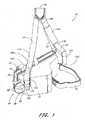
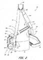
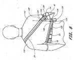
図1および図2に図示されたように、この発明の肩吊り包帯10には、支持ピロー12、前腕ポーチ14、およびピロー12とポーチ14とを装着者に固定する複数のストラップ16,18,20,22が備わっている。この吊り包帯10は、関節上腕の脱旧ならびに亜脱旧および関節包内偏位を治療するときにとりわけ有効である。この吊り包帯10は、術後の回旋筋腱板の修復、術後のバンカート法、および軟組織の挫傷ならびに修復にもとりわけ有効である。この吊り包帯10は、装着者の腕を所望の外転角および外旋角で維持する。 As shown in FIGS. 1 and 2, the shoulder strap 10 of the present invention includes a
特に好ましい実施形態では、吊り包帯10は、装着者の腕をおよそ15°の外転角およびおよそ15°の外旋角で維持することができる。別の特に好ましい実施形態では、吊り包帯10は、装着者の腕をおよそ15°の外転角およびおよそ30°の外旋角で維持することができる。しかしながら、当業者は、吊り包帯10が装着者の腕を事実上任意の外転角、伸展角および回転角で維持することができるということを理解するであろう。これらの角度のそれぞれの大きさは、装着者の背格好ならびに体形、支持ピロー12の寸法ならびに形状、およびストラップ16,18,20,22の長さに左右される。図1および図2は、異なった寸法および形状にされた支持ピロー12を図示している。図1のピロー12は装着者の腕をより小さい外旋角に維持し、図2のピロー12は装着者の腕をより大きい外旋角に維持する。 In a particularly preferred embodiment, the hanging bandage 10 can maintain the wearer's arm at an abduction angle of approximately 15 ° and an abduction angle of approximately 15 °. In another particularly preferred embodiment, the hanging bandage 10 can maintain the wearer's arm at an abduction angle of approximately 15 ° and an abduction angle of approximately 30 °. However, those skilled in the art will appreciate that the suspended bandage 10 can maintain the wearer's arm at virtually any abduction, extension and rotation angle. The magnitude of each of these angles depends on the wearer's back and body shape, the size and shape of the
都合のよいことに、この発明の吊り包帯10は、装着者の右肩か左肩かのいずれかを治療するために使用することができる。図面は、右手用配置における吊り包帯10を図示している。この吊り包帯10は、ストラップ16,18,20,22と前腕ポーチ14をピロー12から取り外し、ピロー12をそれが装着者の左側に置かれるように適合させるためにピロー12を上下逆にし、ストラップ16,18,20,22と前腕ポーチ14をピロー12に再び取り付けることによって、左手用配置に容易に変更される。 Conveniently, the hanging bandage 10 of the present invention can be used to treat either the wearer's right shoulder or left shoulder. The figure illustrates a hanging bandage 10 in a right hand arrangement. The hanging bandage 10 removes the
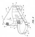
図3によれば、支持ピロー12は、発泡体のような軽量材料から作られたブロック24からなっている。支持ピローの材料は、装着者により大きい快適さをもたらすために、柔らかくて弾性があるのが好ましい。ピロー12の外面はループ状生地からなっているのが好ましい。例えば、ピロー12には発泡体の芯24を覆って布製カバー26が含まれ、カバー26にはループ状外面が備わっている。従って、以下に説明するように、ピローの外面26は、フック生地を容易に受け入れるとともに取り外し可能に固定する。布製カバー26のための好ましい生地は、けば立て加工されたナイロンである。 According to FIG. 3, the
ピロー12の内側面28(図3)は、図6〜図8に図示されたように装着者の腰および胴に接して快適に適合するように、輪郭が付けられている。ピロー12の外側面30は、図6〜図8に図示されたように、平坦であって前腕ポーチ14に接している。内側面28と外側面30との相対的な位置および方位によって、吊り包帯10が装着されたときに装着者の腕が占有する外転角および外旋角が決定される。 The inner surface 28 (FIG. 3) of the
吊り包帯10の右手用配置についての図5によれば、前腕ポーチ14には内側パネル32と外側パネル34が備わっている。吊り包帯10の左手用配置(図示略)では、内側パネル32は実際には外側に位置し、外側パネル34は実際には内側に位置する。説明を簡略にするために、パネル32,34は、吊り包帯10が右手用配置にあるときにそれらが位置しているものとして説明される。 According to FIG. 5 for the right hand arrangement of the hanging bandage 10, the
前腕ポーチ14は、いくらかの剛性といくらかの柔軟性との双方を備えたポーチ14をもたらす材料から構成されているのが好ましい。例えば、好ましい実施形態では、内側パネル32および外側パネル34は、布地からなる第1外側層、発泡体からなる内側層、および布地からなる第2外側層を備えているラミネートからそれぞれ構成されている。 The
パネル32,34の内面36(装着者の腕に接する面)は、木綿−ポリエステル混紡のような柔軟かつ吸湿性の材料からなるのが好ましい。パネル32,34の外面38は、フック生地を受け入れるように適合された耐久性材料からなるのが好ましい。例えば、外面38は、けば立て加工されたナイロンから作ることができる。 The
さらに図5によれば、内側パネル32と外側パネル34とは、それらにおけるそれぞれの下縁40および後縁42に沿って互いに固定されている。パネル32,34は、半分に折り曲げられる単一のシートから形成することができる。折り曲げ線は、ポーチ14の下縁40かあるいは後縁42かのいずれかを形成することができる。この代わりに、パネル32,34は、2つの縁に沿って互いに固定される2つの分離シートから形成することができる。図示された実施形態では、パネル32,34は単一の折り曲げシートから形成されており、また、その折り曲げ線はポーチ14の下縁40を形成している。当業者は、パネル32,34の縁40,42が永久手段および取り外し可能手段の双方を含むさまざまな代わりの手段で互いに固定されてもよいということを理解するであろう。都合のよいことに、外側パネル34の内側面44にはフック生地46からなるパッチが含まれている。フック生地46は、図1および図2に示されたように、前腕ポーチ14をピローの外側面30に取り外し可能に固定するためにピローの外面26におけるループ生地に係合する。ポーチ14の外面には、ポーチ14の残部とは異なった質感を有しているループ生地47からなる細長片(破線によって表示されている)が含まれていてもよい。 Still referring to FIG. 5, the
パネル32,34の上縁48および前縁50は互いに固定されていない。図6〜図8に示されたように、吊り包帯10が装着されると、装着者は彼の前腕をポーチ14の中に置く。装着者の上腕はポーチ14の後方部分から上方へ突き出る(図7)。装着者の手はポーチ14の前縁50から前方へ突き出る。 The upper edge 48 and the front edge 50 of the
図5によれば、内側パネル32の上縁48の前方部分には、第1ストラップ52が第1Dリング54を介して固定されている。外側パネル34の上縁48の前方部分には第2Dリング54が固定されている。外側パネル34の上縁48の後方部分には第2ストラップ56が固定されている。第2ストラップ56には弾性部分58が含まれている。 According to FIG. 5, the first strap 52 is fixed to the front portion of the upper edge 48 of the
図示された実施形態では、縫い付け部60(図5)によってDリング54がパネル32,34に永久に固定されており、また、フック生地(図示略)によって第2ストラップ56がパネル34に取り外し可能に固定されている(図7)。しかしながら、当業者は、Dリング54が代わりの手段によってパネルに固定されてもよいということを理解するであろう。例えば、Dリング54はフック生地を含むストラップ56(図7)に固定されてもよく、また、フック生地はポーチ14の外面に取り外し可能に固定することのできるものでもよい。同様に、ストラップ56は、例えば縫い付けによってパネル34に永久に固定されてもよい。 In the illustrated embodiment, the D-ring 54 is permanently fixed to the
図5、図6および図7に示されたように、ストラップ52は、Dリング54に通されているとともにピロー12へ向かって折り返されている。ストラップ52におけるフック生地は、ピロー12におけるループ生地に係合しているとともにストラップ52をピローに固定している。同様に、ストラップ56は、パネル32,34の上縁48を越えてピロー12へ向かって延びている。ストラップ56におけるフック生地は、ピロー12におけるループ生地に係合しているとともにストラップ56をピローに固定している。ストラップ56の弾性部分58は、ストラップ56がさまざまな箇所でピロー12に係合することができるように、ストラップ56を伸ばすことができる。従って、ストラップ52,56は、図6および図7に示されたように、ポーチ14の上縁48を装着者の腕といっしょに締め付ける。 As shown in FIGS. 5, 6, and 7, the strap 52 is passed through the D ring 54 and folded back toward the
図1および図2によれば、ピロー12の前面62には、都合のよいことに運動用グリップ64が含まれている。図示された実施形態では、グリップ64は弾力性・圧縮性材料から作られた球状ボール66からなっている。当業者は、ボール66が任意の形状であってもよいということを理解するであろう。ボール66は第1および第2の環状ストラップ68によってピロー12に固定されている。これらのストラップ68は、同じ箇所でフック生地からなるパッチ70に固定されている。フック生地からなるパッチ70は、ピロー12におけるループ生地に係合して、ストラップ68をピロー12に固定している。このように、グリップ64は事実上、任意の箇所でピロー12に固定することができる。当業者は、グリップ64が1つの箇所でグリップ64をピロー12に永久に固定する縫い付けによるような他の方法でピロー12に取り付けられてもよい、ということを理解するであろう。 1 and 2, the front surface 62 of the
環状ストラップ68は互いに90°ずれている。従って、ストラップ68は、ボール66の表面の大部分を取り囲んでおり、ボール66がストラップ68から誤って抜けるのを防止している。ボール66をストラップ68の内部に入れるために、あるいはボール66をストラップ68の間から取り外すために、装着者は、2つの隣接ストラップ68を引き離し、分けられたストラップ68の間に作り出された隙間から圧縮性ボール66を強制的に通す。当業者は、ボール66が1つの環状ストラップとこの環状ストラップから90°ずれている1つの半環状ストラップとが備わったような異なるストラップ構成で固定されてもよい、ということを理解するであろう。 The
図示された実施形態では、都合のよいことに、グリップ64はピロー12の前面62と外側面30とを分離するピロー12の縁72に隣接してピロー12に取り付けられている。図6に示されたように、吊り包帯10が装着されると、グリップ64は、装着者が彼あるいは彼女の治療腕における手でそれに容易に届くことのできる場所に配置されている。従って、装着者はストラップ68から運動用グリップ64を取り外すことなくそれを使用することができる。もちろん、必要があれば、装着者は、彼あるいは彼女の手を運動用グリップ64で運動させる前にストラップ68からそれを取り外すことができる。 In the illustrated embodiment, the
図3によれば、胴ストラップ16がピローの内側面28の前縁74と後縁76との間に延びている。胴ストラップ16は、図6および図8に示されたように、装着者の胴を包み込み、支持ピロー12を装着者に固定する。このストラップの後縁78は、内側面28の後縁76に隣接してストラップ82によってピロー12に永久的に固定されたDリング80に通されているのが好ましい。胴ストラップ16の前端84は、第1バックル部分86に通されているのが好ましい。第1バックル部分86は、内側面28の前縁74に隣接してストラップ90によってピロー12に永久的に固定された第2バックル部分88に取り外し可能に係合している。 According to FIG. 3, the
胴ストラップ16のそれぞれの端部78,84には、フック生地92が含まれている。胴ストラップ16の中間部分94にはループ部分(図示略)が含まれている。胴ストラップ16の後端78および前端84は、Dリング80および第1バックル部分86にそれぞれ通されているとともに、胴ストラップ16の中間部分94の上に折り返されている。これらの端部におけるフック面92は、中間部分94でループ面に嵌合状に係合する。従って、胴ストラップ16の長さは、端部78,84が中間部分94に係合する箇所を変えることで調節することができる。当業者は、端部78,84にループ生地が含まれていて中間部分94にフック生地が含まれていてもよい、ということを理解するであろう。 A
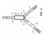
図4によれば、複数のストラップ18,20,22が、肩パッド96に係合しているとともに、図6〜図8に示されたように装着者の非治療肩から吊り包帯10を吊るしている。図示された実施形態では、肩パッド96は装着者の胸を覆って置かれている。装着者の好みにもよるが、肩パッド96は、パッド96の一部が装着者の肩から前方へ延びるように、かつ、パッド96の一部が装着者の肩から後方へ延びるように、装着者の肩を覆って置かれてもよい。 According to FIG. 4, a plurality of
ストラップ18,20,22は、ナイロン布地のような柔軟で耐久性のある材料から構成されているのが好ましい。肩パッド96は、緩衝性と弾力性がある材料からなる細長片から構成されているのが好ましく、また、複数の層から構成されていてもよい。例えば、このパッドには、ナイロンのような耐久性布地からなる外側層によって覆われた、弾力のある発泡材料からなる内側層が備わっていてもよい。図示された実施形態ではパッド96は長方形である。しかしながら、当業者は肩パッド96が任意の形状であってよいということを理解するであろう。 The
図示された実施形態では、ストラップ18,20,22の上端98,100,102は、縫い付け部104によって肩パッド96に永久に固定されている。当業者は、ストラップ18,20,22がさまざまな代わりの手段によって肩パッド96に固定されていてもよい、ということを理解するであろう。例えば、フックおよびループの生地によってストラップ18,20,22が肩パッド96に取り外し可能に固定されていてもよい。 In the illustrated embodiment, the upper ends 98, 100, 102 of the
図1および図2によれば、胸ストラップ18が、肩パッド96の前縁106から支持ピロー12の前面62まで下方へ延びている。胸ストラップ18の下端108にはフック生地110が含まれている。ストラップ18の下端108は、第1バックル部分112に通されているともに、胸ストラップ18の中間部分114の上へ折り返されている。この中間部分114にはループ生地(図示略)が含まれている。このように、下端108は、胸ストラップ18の長さを調節することができるように、さまざまな箇所で中間部分114に取り外し可能に固定することができる。第1バックル部分112は、ストラップ118によってピローの前面62に永久的に固定された第2バックル部分116に取り外し可能に係合している。 According to FIGS. 1 and 2, the
図6および図8によれば、背ストラップ20が、肩パッド96の後縁120から腕ポーチ14の後縁42まで下方へ延びている。背ストラップ20の下端122にはフック生地(図示略)が含まれている。背ストラップ20のこの下端は、ストラップ126を介してポーチ14の上方後縁42に永久に固定されたDリング124に通されている。この下端122は、背ストラップ20の中間部分128の上へ折り返されている。この中間部分128にはループ生地(図示略)が含まれている。このように、下端122は、背ストラップ20の長さを調節することができるように、さまざまな箇所で中間部分128に取り外し可能に固定することができる。 According to FIGS. 6 and 8, the
図1、図2、図6および図8によれば、回転防止ストラップ22が、肩パッド96の前縁106から支持ピロー12の後面130(図8)まで下方へかつ装着者の胴の周りに延びている。回転防止ストラップ22の下端132にはフック生地(図示略)が含まれている。ストラップ22のこの下端は、ストラップ136を介してピローの後面130に永久に固定されたDリング134に通されている。この下端132は、回転防止ストラップ22の中間部分138の上へ折り返されている。この中間部分138にはループ生地が含まれている。このように、下端132は、回転防止ストラップ22の長さを調節することができるように、さまざまな箇所で中間部分138に取り外し可能に固定することができる。 According to FIGS. 1, 2, 6 and 8, the
図1、図2および図4によれば、回転防止ストラップ22には、都合のよいことにパッド入りスリーブ140が含まれている。図示された実施形態では、スリーブ140には、筒を形成するために半分に折り曲げられて縫われた長方形パッドが備わっている。当業者は、スリーブ140が2つの長方形パッドを2つの縁に沿って互いに縫い合わせることによるようなさまざまな他の方法で形成されていてもよい、ということを理解するであろう。スリーブ140は、緩衝性・弾力性材料から構成されているのが好ましく、また、複数の層から構成されていてもよい。例えば、このスリーブ140には、ナイロンのような耐久性布地からなる外側層によって覆われた、弾力のある発泡材料からなる内側層が備わっていてもよい。 According to FIGS. 1, 2, and 4, the
スリーブ140には、回転防止ストラップ22と装着者との間に緩衝層が設けられ、それによって、吊り包帯10を装着している間の装着者の快適さが増大するようにされている。スリーブ140は、装着者がスリーブ140を最も快適な状態に位置させることができるように、回転防止ストラップ22に沿ってスライドすることのできるものであるのが好ましい。例えば、図6および図8では、装着者は、スリーブ140をそれが胸筋および肋骨の上を覆うように位置させている。 The
図6および図8によれば、回転防止ストラップ22は、吊り包帯10が装着者に対して動くのを都合よく制限する。ピロー12が装着者の胴に対して回転しがちであることによって、ピロー12を反対方向へ引く傾向のある回転防止ストラップ22における張力が作り出される。例えば、ピロー12に作用してそれを装着者に対して回転させて装着者の背中へ向けて引く傾向のある力によって、胸ストラップ18には、肩パッド96を装着者の治療肩142へ向けて引く傾向のある張力が作り出される。肩パッド96にかかる力によって、回転防止ストラップ22には、肩パッド96を装着者の非治療肩144へ向けて後方に引く傾向のある張力が作り出される。同じように、ピロー12に作用してそれを装着者の腹部へ向けて回転させる傾向のある力によって、背ストラップ20には、肩パッド96を装着者の治療肩142へ向けて引く傾向のある張力が作り出される。肩パッド96にかかる力によって、回転防止ストラップ22には、肩パッド96を装着者の非治療肩144へ向けて後方に引く傾向のある張力が作り出される。このように、回転防止ストラップ22によって、吊り包帯10が所望の外転角および外旋角で装着者の腕を保持することが可能になり、装着者の肩142を治療するときにおける吊り包帯10の有効性が増大する。 According to FIGS. 6 and 8, the
図6〜図8には、装着者に装着された吊り包帯10が図示されている。支持ピロー12は、治療肩142の下で装着者の腰に置かれている。ピローの内側面28は装着者の腰と胴に接しており、装着者の前腕はポーチ14の内部に置かれている。肩パッド96は装着者の非治療肩144の上に置かれている。胸ストラップ18は、肩パッド96から対角線状に下方へ、かつ、装着者の胸を横切って、支持ピロー12の前方部分62まで延びている。背ストラップ20は、肩パッド96から対角線状に下方へ、かつ、装着者の背中を横切って、腕ポーチ14の上方後縁42まで延びている。回転防止ストラップ22は、肩パッド96から対角線状に下方へ、かつ、装着者の胸を横切って、非治療肩144の下で装着者の胴の周りに、かつ、装着者の背中を横切って、支持ピロー12の後面130まで延びている。 6 to 8 show the hanging bandage 10 attached to the wearer. The
典型的には、医師は初めに吊り包帯10を装着者へ装着する。吊り包帯10は、相異なる体形の装着者に装着するために、さまざまな寸法で入手することのできるものであるのが好ましい。図6〜図8に示されたように、適切な寸法の吊り包帯10を装着者に適用した後に、医師は、胴ストラップ16が装着者のウエストに対してぴったりと装着されるように、胴ストラップ16の長さを調節する。医師は、胸ストラップ18、背ストラップ20および回転防止ストラップ22が所望の外転角および外旋角で装着者の腕を適切に支持するまで、これらのストラップ18,20,22の長さも調節する。 Typically, the physician first wears the hanging bandage 10 on the wearer. The hanging bandage 10 is preferably available in various dimensions for attachment to wearers of different body shapes. As shown in FIGS. 6-8, after applying an appropriately sized hanging bandage 10 to the wearer, the physician may use the torso so that the
図3によれば、都合のよいことに、支持ピロー12の上面146には、医師がストラップ18,20,22を適切に調節するために利用することのできるまっすぐな表示線148が含まれている。医師は、彼あるいは彼女が吊り包帯10を装着者に装着するときに表示線148の方位を観察する。線148が装着者の身体の正中横軸に対して平行であるときには、ストラップ18,20,22は所望の外旋角について適切に調節されている。医師が吊り包帯10を適切に方向付けするのに役立つように、彼あるいは彼女は装着者を壁に対向するように位置させる。医師は次いで、表示線148が壁に対して平行であるかどうかを判定し、必要に応じてストラップ調節を行う。装着者を壁にきわめて近く位置させることによって、医師は、表示線148が壁に対して平行であるときには壁と表示線148の上のさまざまな箇所との間の距離が互いに等しいということを確認するために、計測することさえできる。 According to FIG. 3, conveniently, the
吊り包帯10が適切に装着されると、装着者は、彼自身あるいは彼女自身によって、吊り包帯10を容易に取り外して再び適用することができる。吊り包帯10を取り外すためには、装着者は、胴ストラップ16および胸ストラップ18における第1バックル部分および第2バックル部分を単に外すだけでよい。重力によって支持ピロー12は地面へ向かって引かれ、また、吊り包帯10の全体は、肩パッド96によって装着者の非治療肩144から吊るされる。装着者は次いで、肩パッド96を掴んで、背ストラップ20と回転防止ストラップ22との間の空間を通して彼あるいは彼女の非治療腕を引き抜く。 Once the hanging bandage 10 is properly worn, the wearer can easily remove and reapply the hanging bandage 10 by himself or herself. To remove the suspended bandage 10, the wearer simply needs to remove the first and second buckle portions on the
吊り包帯10を迅速かつ容易に適用するためには、装着者は手始めに、胸ストラップ18の第1バックル部分112および第2バックル部分116を外し、また、胴ストラップ16における第1バックル部分86および第2バックル部分88を外す。胴ストラップ16、背ストラップ20および回転防止ストラップ22はそれぞれ、それらの各Dリングに接続されている。装着者は、彼あるいは彼女の腕をポーチ14の中に置いてストラップ52,56を固定する。次に、装着者は、治療肩142の下で彼あるいは彼女の身体の側部にピロー12を置き、第1バックル部分86および第2バックル部分88を再び接続することで、ピロー12を胴ストラップ16に固定する。装着者は、彼あるいは彼女の非治療腕144をストラップ20とストラップ22との間の開口に挿入し、パッド96を肩144の上に位置させる。最後に、装着者は、第1バックル部分112および第2バックル部分116を接続することで胸ストラップ18を固定する。 To apply the hanging bandage 10 quickly and easily, the wearer first removes the
上記のことは、この発明の肩吊り包帯を実施するために意図されたベストモード、およびそれを製造しかつ使用する方法および方式を、この肩吊り包帯の製造および使用に関する当業者に可能であるように、充分に、明確に、簡潔に、かつ正確な用語で記載することを表わしている。しかしながら、この肩吊り包帯は、充分に等価である、上で検討されたものから修正および代わりの構成を受けることができる。従って、この肩吊り包帯は開示された特定の実施形態に限定されない。これに反して、この肩吊り包帯には、肩吊り包帯の主題を特に指摘しかつはっきりと権利要求する特許請求の範囲によって広く表現されたように、肩吊り包帯の精神および範囲の内部に入るすべての修正および代わりの構成が含まれている。 The above allows the person skilled in the art of making and using the shoulder bandage the best mode intended to implement the shoulder bandage of the present invention and the method and manner of making and using it. As such, it is expressed clearly, concisely and accurately in terms of terms. However, this shoulder strap can be subject to modifications and alternative configurations from those discussed above that are sufficiently equivalent. Accordingly, the shoulder bandage is not limited to the specific embodiments disclosed. On the contrary, this shoulder bandage falls within the spirit and scope of the shoulder bandage, as broadly expressed by the claims that specifically point out and explicitly claim the subject matter of the shoulder bandage. All modifications and alternative configurations are included.
Claims (25)
Translated fromJapanese装着者の前腕を受け入れるとともにその前腕を少なくとも部分的に囲い込むポーチ、および
支持ピローとポーチとを装着者に固定する複数のストラップ
を備えてなり、
内側面の前縁と外側面の前縁との距離は、内側面の後縁と外側面の後縁との距離よりも実質的に大きい
装着者の腕を所望の外転角および外旋角で支持する肩吊り包帯。A support pillow including a contoured inner surface for contacting the wearer's torso and an outer surface operatively contacting and supporting the wearer's arm;
A pouch that receives and at least partially encloses the forearm of the wearer, and a plurality of straps that secure the support pillow and pouch to the wearer;
The distance between the front edge of the inner surface and the front edge of the outer surface is such that the wearer's arm is substantially larger than the distance between the rear edge of the inner surface and the rear edge of the outer surface. Shoulder hanging bandage supported by.
支持ピローに固定されて装着者の前腕を受け入れるとともにその前腕を少なくとも部分的に囲い込むポーチ、および
支持ピローとポーチとを装着者に固定する複数のストラップ
を備えてなり、
ストラップのうち第1のものは、支持ピローの前面から肩パッドの前縁まで延びている胸ストラップからなり、
ストラップのうち第2のものは、ポーチの後縁から肩パッドの後縁まで延びている背ストラップからなり、
ストラップのうち第3のものは、肩パッドの前縁から前記内側面に隣接して支持ピローまで延びている回転防止ストラップからなっている
装着者の腕を所望の外転角および外旋角で支持する肩吊り包帯。A support pillow operatively contacting the wearer's arm and including an outer surface that supports the arm;
A pouch that is secured to the support pillow and receives the wearer's forearm and at least partially encloses the forearm, and a plurality of straps that secure the support pillow and pouch to the wearer;
The first of the straps consists of a chest strap that extends from the front of the support pillow to the front edge of the shoulder pad,
The second of the straps consists of a back strap that extends from the rear edge of the pouch to the rear edge of the shoulder pad,
A third of the straps has a desired abduction and rotation angle on the wearer's arm comprising an anti-rotation strap that extends from the front edge of the shoulder pad to the support pillow adjacent the inner surface. Supporting shoulder bandage.
装着者の前腕を受け入れるとともにその前腕を少なくとも部分的に囲い込むポーチ、および
支持ピローとポーチとを装着者に固定する複数のストラップ
を備えてなり、
支持ピローの上面は、吊り包帯が適切に装着されたときに装着者がわかるように装着者へ視覚的手掛かりをもたらすまっすぐな表示線を含んでいる
装着者の腕を所望の外転角および外旋角で支持する肩吊り包帯肩吊り包帯。A support pillow including a contoured inner surface for contacting the wearer's torso and an outer surface operatively contacting and supporting the wearer's arm;
A pouch that receives and at least partially encloses the forearm of the wearer, and a plurality of straps that secure the support pillow and pouch to the wearer;
The upper surface of the support pillow provides a desired abduction angle and outer surface that includes a straight line that provides a visual clue to the wearer so that the wearer can see when the suspension bandage is properly worn. Shoulder suspension bandage to support at a turning angle.
装着者の前腕を受け入れるとともにその前腕を少なくとも部分的に囲い込むポーチ、
支持ピローとポーチとを装着者に固定する複数のストラップ、および
支持ピローの前方部分に固定された運動用グリップ
を備えてなる
装着者の腕を所望の外転角および外旋角で支持する肩吊り包帯。A support pillow including a contoured inner surface for contacting the wearer's torso and an outer surface operatively contacting and supporting the wearer's arm;
A pouch that accepts the wearer's forearm and at least partially surrounds the forearm;
A shoulder for supporting the wearer's arm at a desired abduction angle and rotation angle with a plurality of straps for securing the support pillow and pouch to the wearer, and an exercise grip secured to the front portion of the support pillow Hanging bandage.
支持ピローを装着者に固定する複数のストラップ
を備えてなり、
内側面の前縁と外側面の前縁との距離は、内側面の後縁と外側面の後縁との距離よりも実質的に大きい
装着者の腕を所望の外転角および外旋角で支持する肩吊り包帯。A support pillow including an inner surface contoured to contact the wearer's torso and an outer surface operatively contacting and supporting the wearer's arm, and securing the support pillow to the wearer With multiple straps,
The distance between the front edge of the inner surface and the front edge of the outer surface is such that the wearer's arm is substantially larger than the distance between the rear edge of the inner surface and the rear edge of the outer surface. Shoulder hanging bandage supported by.
支持ピローの外側面と協働して装着者の前腕を少なくとも部分的に囲い込むように適合されたポーチ、
装着者の肩の上に置かれるように適合された肩パッド、および
支持ピローとポーチとを装着者に固定するように適合された複数のストラップ
を備えてなり、
第1のストラップは、装着者の胴の周りに延びて支持ピローの内側面をそれとともに当接状態に維持するように適合された胴ストラップからなり、
第2のストラップは、支持ピローの前方部分を支持するように、かつ、支持ピローの前方部分を肩パッドの前縁から吊るすように適合された胸ストラップからなり、
第3のストラップは、支持ピローの後方部分を支持するように、かつ、支持ピローの後方部分を肩パッドの後縁から吊るすように適合された背ストラップからなっている
装着者の腕を所望の外転角および外旋角で支持する肩吊り包帯。A support pillow including a contoured inner surface adapted to contact the wearer's torso and an outer surface adapted to support the wearer's forearm;
A pouch adapted to cooperate with the outer surface of the support pillow to at least partially enclose the forearm of the wearer;
A shoulder pad adapted to be placed on the shoulder of the wearer and a plurality of straps adapted to secure the support pillow and pouch to the wearer;
The first strap comprises a torso strap that extends around the wearer's torso and is adapted to keep the inner surface of the support pillow in contact therewith;
The second strap comprises a chest strap adapted to support the front portion of the support pillow and to hang the front portion of the support pillow from the front edge of the shoulder pad;
The third strap provides a desired arm of the wearer comprising a back strap adapted to support the rear portion of the support pillow and to suspend the rear portion of the support pillow from the rear edge of the shoulder pad. A shoulder bandage supported at an abduction angle and an external rotation angle.
Applications Claiming Priority (2)
| Application Number | Priority Date | Filing Date | Title |
|---|---|---|---|
| US10/663,381US7563236B2 (en) | 2003-09-15 | 2003-09-15 | Shoulder sling with support pillow and pouch |
| PCT/US2004/029976WO2005027805A2 (en) | 2003-09-15 | 2004-09-13 | Shoulder sling |
Publications (1)
| Publication Number | Publication Date |
|---|---|
| JP2007505651Atrue JP2007505651A (en) | 2007-03-15 |
Family
ID=33565316
Family Applications (1)
| Application Number | Title | Priority Date | Filing Date |
|---|---|---|---|
| JP2006526394APendingJP2007505651A (en) | 2003-09-15 | 2004-09-13 | Shoulder strap |
Country Status (5)
| Country | Link |
|---|---|
| US (1) | US7563236B2 (en) |
| EP (1) | EP1663083A2 (en) |
| JP (1) | JP2007505651A (en) |
| CA (1) | CA2537908A1 (en) |
| WO (1) | WO2005027805A2 (en) |
Cited By (8)
| Publication number | Priority date | Publication date | Assignee | Title |
|---|---|---|---|---|
| KR101031453B1 (en)* | 2010-08-06 | 2011-04-26 | 선동윤 | Medical arm support |
| KR200473627Y1 (en) | 2013-01-08 | 2014-07-15 | 김기준 | Assisting armrest for shoulder joint |
| JP2015503409A (en)* | 2012-01-06 | 2015-02-02 | オーペーエーデー アー・ゲー | Orthopedic appliance and method for placement of orthopedic appliance |
| JP2015195870A (en)* | 2014-03-31 | 2015-11-09 | アルケア株式会社 | Shoulder brace |
| JP2016073516A (en)* | 2014-10-08 | 2016-05-12 | 有限会社永野義肢 | Shoulder joint abduction brace |
| KR101783537B1 (en) | 2016-01-14 | 2017-10-10 | 선문대학교 산학협력단 | Shoulder brace |
| KR20180001527U (en)* | 2017-09-14 | 2018-05-24 | 주식회사 삼부메디칼 | Arm Fixing Device for the Sick |
| JP2022520048A (en)* | 2019-02-07 | 2022-03-28 | ケーシーアイ ライセンシング インコーポレイテッド | Contoured foam dressing shaped to provide negative pressure for the shoulder incision |
Families Citing this family (66)
| Publication number | Priority date | Publication date | Assignee | Title |
|---|---|---|---|---|
| JP2004261531A (en)* | 2003-01-08 | 2004-09-24 | At Lab:Kk | Device for shoulder joint luxation acute phase fixation |
| US20040181180A1 (en)* | 2003-03-14 | 2004-09-16 | Wood Thomas Oval | Wood airway, neck, and head support |
| JP4566582B2 (en)* | 2004-03-02 | 2010-10-20 | 栄二 井樋 | Shoulder joint orthosis |
| US7244239B2 (en)* | 2004-06-04 | 2007-07-17 | Breg, Inc. | Shoulder stabilizing restraint |
| US7749179B2 (en)* | 2005-05-13 | 2010-07-06 | Djo, Llc | Device for stabilizing an arm |
| FR2898041B1 (en)* | 2006-03-06 | 2008-10-17 | Sober Sa Lab | EQUIPMENT FOR DEVICE FOR MAINTAINING A SUPERIOR MEMBER OF A PATIENT |
| FR2898040B1 (en)* | 2006-03-06 | 2008-11-14 | Sober Sa Lab | DEVICE FOR MAINTAINING THE SHOULDER OF A PATIENT |
| FR2905261B1 (en)* | 2006-09-05 | 2008-10-17 | Sober Sa Lab | DEVICE FOR MAINTAINING THE SHOULDER OF A PATIENT. |
| US20080119770A1 (en)* | 2006-11-21 | 2008-05-22 | Miller Drew V | Sling for supporting an arm |
| WO2008105671A1 (en)* | 2007-02-27 | 2008-09-04 | Margaret Kathleen Olds | Shoulder stability brace |
| US20090000625A1 (en)* | 2007-06-29 | 2009-01-01 | Alfery David D | Patient Arm Pad |
| US20090250073A1 (en)* | 2007-06-29 | 2009-10-08 | Mizuho Osi | Patient Arm Pad with Adjustment |
| US8273040B1 (en)* | 2008-12-01 | 2012-09-25 | Ramoned Morrow | Attitude adjustable arm sling |
| US20100152635A1 (en)* | 2008-12-15 | 2010-06-17 | Borden Peter S | Magnetic arm sling |
| US8016780B1 (en) | 2009-01-02 | 2011-09-13 | George Sickles | Orthopedic brace |
| GB0900939D0 (en) | 2009-01-21 | 2009-03-04 | Nhs South West Essex | Shoulder stabilising device |
| IT1395242B1 (en)* | 2009-08-17 | 2012-09-05 | Montani | SUPPORT FOR REHABILITATION THERAPIES |
| WO2011034626A2 (en) | 2009-09-21 | 2011-03-24 | Mahler Sheila J | Orthopedic support pillow |
| EP2501345A4 (en) | 2009-11-18 | 2017-12-06 | Cradle Medical, Inc. | Shoulder immobilizer and fracture stabilization device |
| US9216700B2 (en)* | 2010-03-25 | 2015-12-22 | Kara Gordon | Handbag holder for vehicles |
| US9877861B2 (en) | 2010-06-11 | 2018-01-30 | Elizur Corporation | Shoulder and arm orthosis |
| US20110313335A1 (en)* | 2010-06-18 | 2011-12-22 | Brown Medical Industries | Therapy device and methods of use thereof |
| US8523795B2 (en) | 2010-12-10 | 2013-09-03 | Top Shelf Manufacturing, Llc | Arm sling with backpack straps |
| US8414512B2 (en) | 2011-02-11 | 2013-04-09 | Breg, Inc. | Shoulder orthosis having a supportive strapping system |
| US9498369B2 (en)* | 2012-05-04 | 2016-11-22 | Bryan E. Kilbey | Modular shoulder external rotation wedge system and method |
| US20130317401A1 (en)* | 2012-05-24 | 2013-11-28 | Fancastic Products, Inc. | Shoulder abduction sling-pillow-immobilizer system |
| FR2991224B1 (en)* | 2012-06-04 | 2014-06-27 | Commissariat Energie Atomique | ARM OF EXOSQUELET WITH ACTUATOR |
| US8418897B1 (en) | 2012-08-27 | 2013-04-16 | Anthony Young | Body worn child carrier |
| US8523028B1 (en) | 2012-08-27 | 2013-09-03 | Anthony Young | Body worn child carrier |
| US8845565B1 (en) | 2012-10-19 | 2014-09-30 | B. Rodney Burns | Arm sling neck cushion kit |
| US9326906B2 (en) | 2012-11-29 | 2016-05-03 | Edwinia Thanas | Therapeutic pillow |
| US11638656B2 (en) | 2012-12-31 | 2023-05-02 | Xtreme Orthopedics Llc | Shoulder and arm restraint |
| US10398585B2 (en) | 2013-05-30 | 2019-09-03 | Xtreme Orthopedics Llc | Shoulder and arm restraint |
| USD962450S1 (en) | 2013-05-30 | 2022-08-30 | Extreme Orthopedics Llc | Shoulder immobilizer pillow |
| US10231882B2 (en) | 2013-09-10 | 2019-03-19 | Xtreme Orthopedics Llc | Device and method for applying pressure to a mammalian limb |
| ITMI20131491A1 (en)* | 2013-09-10 | 2015-03-11 | Orthoservice Ag | TUTOR FOR THE IMMOBILIZATION OF A TRAUMATED OR OPERATED SHOULDER |
| US10973305B2 (en)* | 2013-10-18 | 2021-04-13 | Stephen M. Plante | Load bearing positioning system and method |
| USD728806S1 (en) | 2013-11-13 | 2015-05-05 | Wesley Cox | Elbow brace |
| US10045626B1 (en)* | 2014-08-25 | 2018-08-14 | Stephen H Cheetham | Portable elbow rest and method of use |
| US20200368057A1 (en)* | 2015-06-25 | 2020-11-26 | Pascal Boileau | Upper Extremity Braces |
| ES2734679T3 (en)* | 2015-06-25 | 2019-12-11 | Pascal Boileau | Improvements in or related to upper limb orthopedic clamps |
| CN105055066A (en)* | 2015-07-22 | 2015-11-18 | 重庆医科大学附属儿童医院 | Pronated deformity orthopedic appliance for upper limbs |
| USD799709S1 (en) | 2015-09-11 | 2017-10-10 | Xtreme Orthopedics Llc | Support brace |
| USD800325S1 (en) | 2015-09-11 | 2017-10-17 | Xtreme Orthopedics Llc | Triceps support with elbow compression sleeve |
| USD800323S1 (en) | 2015-09-11 | 2017-10-17 | Xtreme Orthopedics Llc | Compression sleeve |
| USD800326S1 (en) | 2015-09-11 | 2017-10-17 | Xtreme Orthopedics Llc | Support brace |
| USD799708S1 (en) | 2015-09-11 | 2017-10-10 | Xtreme Orthopedics Llc | Shin splint with calf support brace |
| USD800324S1 (en) | 2015-09-11 | 2017-10-17 | Xtreme Orthopedics Llc | Knee compression sleeve |
| WO2017062507A1 (en) | 2015-10-05 | 2017-04-13 | Tactile Systems Technology, Inc. | Adjustable compression garment |
| EP3405152B1 (en) | 2016-01-21 | 2022-03-30 | Tactile Systems Technology, Inc. | Compression garment system |
| US12083063B1 (en) | 2017-01-27 | 2024-09-10 | George Sickles | Orthopedic brace |
| US10912667B1 (en) | 2017-01-27 | 2021-02-09 | George Sickles | Orthopedic brace |
| USD834208S1 (en) | 2017-03-10 | 2018-11-20 | Tactile Systems Technology, Inc. | Chest and arm garment |
| US10722040B2 (en) | 2017-06-05 | 2020-07-28 | Timothy Aaron Denman | Wearable elbow and shoulder non-impingement pillow |
| WO2019090339A1 (en) | 2017-11-06 | 2019-05-09 | Tactile Systems Technology, Inc. | Compression garment systems |
| US11109995B1 (en) | 2018-01-19 | 2021-09-07 | Deroyal Industries, Inc. | Shoulder support system |
| USD1072258S1 (en) | 2018-11-01 | 2025-04-22 | Guy Kennedy | Shoulder abduction arm support |
| US10935254B2 (en) | 2018-11-02 | 2021-03-02 | Kevin Toomey | Pipe heating device |
| US12268626B2 (en) | 2019-03-26 | 2025-04-08 | Orthocare Medical Equipment, Llc | Comfort harness for orthotic brace |
| US11602451B1 (en) | 2019-06-27 | 2023-03-14 | Preferred Prescription, Inc. | Shoulder sling with air abduction pad |
| WO2021081173A1 (en)* | 2019-10-23 | 2021-04-29 | Ossur Iceland Ehf | Shoulder immobilizer and arm apparatus |
| US12213903B2 (en) | 2019-10-23 | 2025-02-04 | Ossur Iceland Ehf | Positioning wedge |
| US20220387207A1 (en)* | 2021-06-03 | 2022-12-08 | William R. Post. | Shoulder brace and method |
| US12290464B1 (en)* | 2021-12-29 | 2025-05-06 | Steven McGrath | Arm support apparatus |
| WO2023211953A1 (en) | 2022-04-26 | 2023-11-02 | Gen3 Medical, LLC | Device for immobilizing a shoulder |
| US20240139020A1 (en)* | 2022-11-01 | 2024-05-02 | Bryan E. Kilbey | System & Method for Providing a Reconfigurable Sling |
Family Cites Families (37)
| Publication number | Priority date | Publication date | Assignee | Title |
|---|---|---|---|---|
| US2310556A (en) | 1941-04-11 | 1943-02-09 | George F Strong | Electric welding machine |
| US3404680A (en)* | 1965-10-22 | 1968-10-08 | Alexander P. Guttman | Shoulder sling |
| US3788308A (en) | 1972-10-02 | 1974-01-29 | C Simpson | Neck sling pad |
| DE2615209A1 (en) | 1975-04-15 | 1976-10-28 | Teufel Wilh Jul Fa | UNIVERSAL ORTHESIS |
| US4372301A (en) | 1981-04-14 | 1983-02-08 | Tecnol, Inc. | Arm sling |
| US4598701A (en) | 1984-05-11 | 1986-07-08 | Span-America Medical Systems, Inc. | Shoulder abduction splint |
| US4716895A (en)* | 1984-06-11 | 1988-01-05 | Marques Jean S | Arm sling |
| US4617923A (en) | 1985-01-24 | 1986-10-21 | Michael Coleman | Sling |
| US4622961A (en) | 1985-04-04 | 1986-11-18 | Margery Christensen | Arm sling with mitten pocket |
| US4625719A (en) | 1985-07-16 | 1986-12-02 | Chambers David H | Adjustable arm sling |
| US4834082A (en) | 1988-05-02 | 1989-05-30 | Ghadiali Nafisa Z | Arm sling for stroke patients |
| DE3827981A1 (en)* | 1988-08-18 | 1990-02-22 | Gmt Medizinische Technik Gmbh | ABDUCTION PILLOW |
| US4896660A (en) | 1988-09-16 | 1990-01-30 | Scott James W | Arm elevator support device |
| USD317840S (en)* | 1989-12-04 | 1991-07-02 | Dan Jagdat | Pillow |
| US5383844A (en) | 1992-09-21 | 1995-01-24 | Smith & Nephew Donjoy, Inc. | Humeral fracture brace |
| US5407420A (en) | 1992-11-12 | 1995-04-18 | Smith & Nephew Donjoy, Inc. | Fully adjustable shoulder brace |
| US5334132A (en) | 1993-04-16 | 1994-08-02 | Burkhead Wayne Z | Convertible arm sling |
| US5830165A (en) | 1994-01-03 | 1998-11-03 | Rowe; Denis O. | Upper extremity swathe sling apparatus |
| US5423333A (en) | 1994-02-23 | 1995-06-13 | Orthopedic Systems, Inc. | Apparatus for shoulder immobilization |
| US5407430A (en)* | 1994-03-21 | 1995-04-18 | Peters; Michael J. | Intravenous catheter |
| US5413552A (en) | 1994-06-06 | 1995-05-09 | Iwuala; Gloria D. | Arm sling with humeral stabilizer |
| US5569172A (en) | 1994-08-02 | 1996-10-29 | Padden; John | Device for supporting and immobilizing a patient's arm and shoulder and method thereof |
| US5464383A (en) | 1994-08-02 | 1995-11-07 | Padden; John | Device for supporting and immobilizing a patient's arm and shoulder and method therefor |
| GB9507724D0 (en) | 1995-04-13 | 1995-05-31 | Innovative Care Ltd | An improved orthosiss for the shoulder and arm |
| AU128517S (en) | 1996-01-12 | 1996-11-05 | Orthotic Consultants Asia Pacific Pty Ltd | Shoulder abduction pillow |
| US5792083A (en)* | 1996-06-17 | 1998-08-11 | Joslin; Marianne | Arm sling |
| US5772617A (en) | 1996-10-09 | 1998-06-30 | A&B Stablizer, Inc. | Stabilizing arm sling |
| EP0904752A1 (en) | 1997-09-30 | 1999-03-31 | Habermeyer, Peter, Prof. Dr. med. | Bandage system |
| FR2771625B1 (en) | 1997-09-30 | 2000-02-18 | Kinwork | MODULAR ATTACHMENT FOR IMMOBILIZATION OF THE TOP MEMBER |
| US6007500A (en)* | 1998-01-28 | 1999-12-28 | Quintinskie, Jr.; John J. | Shoulder, rotator cuff, and elbow stretching machine |
| US6113562A (en)* | 1998-06-01 | 2000-09-05 | Peter M. Bonutti | Shoulder orthosis |
| JP3479258B2 (en)* | 2000-04-20 | 2003-12-15 | アルケア株式会社 | Shoulder joint orthosis |
| JP2003068426A (en)* | 2001-08-24 | 2003-03-07 | Canon Inc | Power control device |
| DE20120016U1 (en) | 2001-12-11 | 2002-05-23 | Berhorst, Günther, 37287 Wehretal | Orthosis for the treatment of injuries to the A-C joint of the shoulder, especially Tossy 1/2/3 |
| US6659971B2 (en)* | 2002-03-27 | 2003-12-09 | Medical Specialties, Inc. | Shoulder abduction sling |
| JP2004261531A (en)* | 2003-01-08 | 2004-09-24 | At Lab:Kk | Device for shoulder joint luxation acute phase fixation |
| US7189213B1 (en)* | 2003-11-21 | 2007-03-13 | Weber Orthopedic Inc. | Arm support in sling |
- 2003
- 2003-09-15USUS10/663,381patent/US7563236B2/ennot_activeExpired - Lifetime
- 2004
- 2004-09-13EPEP04783985Apatent/EP1663083A2/ennot_activeCeased
- 2004-09-13JPJP2006526394Apatent/JP2007505651A/enactivePending
- 2004-09-13CACA002537908Apatent/CA2537908A1/ennot_activeAbandoned
- 2004-09-13WOPCT/US2004/029976patent/WO2005027805A2/enactiveApplication Filing
Cited By (8)
| Publication number | Priority date | Publication date | Assignee | Title |
|---|---|---|---|---|
| KR101031453B1 (en)* | 2010-08-06 | 2011-04-26 | 선동윤 | Medical arm support |
| JP2015503409A (en)* | 2012-01-06 | 2015-02-02 | オーペーエーデー アー・ゲー | Orthopedic appliance and method for placement of orthopedic appliance |
| KR200473627Y1 (en) | 2013-01-08 | 2014-07-15 | 김기준 | Assisting armrest for shoulder joint |
| JP2015195870A (en)* | 2014-03-31 | 2015-11-09 | アルケア株式会社 | Shoulder brace |
| JP2016073516A (en)* | 2014-10-08 | 2016-05-12 | 有限会社永野義肢 | Shoulder joint abduction brace |
| KR101783537B1 (en) | 2016-01-14 | 2017-10-10 | 선문대학교 산학협력단 | Shoulder brace |
| KR20180001527U (en)* | 2017-09-14 | 2018-05-24 | 주식회사 삼부메디칼 | Arm Fixing Device for the Sick |
| JP2022520048A (en)* | 2019-02-07 | 2022-03-28 | ケーシーアイ ライセンシング インコーポレイテッド | Contoured foam dressing shaped to provide negative pressure for the shoulder incision |
Also Published As
| Publication number | Publication date |
|---|---|
| US7563236B2 (en) | 2009-07-21 |
| US20050010147A1 (en) | 2005-01-13 |
| CA2537908A1 (en) | 2005-03-31 |
| WO2005027805A2 (en) | 2005-03-31 |
| EP1663083A2 (en) | 2006-06-07 |
| WO2005027805A3 (en) | 2005-06-23 |
Similar Documents
| Publication | Publication Date | Title |
|---|---|---|
| JP2007505651A (en) | Shoulder strap | |
| US11179265B2 (en) | Shoulder and arm restraint | |
| US10966853B2 (en) | Shoulder and arm orthosis | |
| US8454544B2 (en) | Method and apparatus for therapeutically supporting the arm of a patient | |
| US7871388B2 (en) | Posture improvement device and method of use | |
| US6918885B2 (en) | Vest having arm sling | |
| US5334132A (en) | Convertible arm sling | |
| TW200528077A (en) | Back support pad | |
| US11638656B2 (en) | Shoulder and arm restraint | |
| US20110213282A1 (en) | Arm sling for post trauma patients | |
| US20080119770A1 (en) | Sling for supporting an arm | |
| JP3035558U (en) | Shoulder joint orthosis | |
| US20030163069A1 (en) | Arm sling | |
| CN212547300U (en) | An inflatable shoulder joint fixation support | |
| JP6285017B2 (en) | Shoulder orthosis for treatment of acromioclavicular dislocation or distal clavicle fracture | |
| CN222367113U (en) | Shoulder joint protective equipment | |
| CN220197700U (en) | A kind of flexible exoskeleton auxiliary clothing | |
| JP6360416B2 (en) | Shoulder pain relief device | |
| CN223158474U (en) | Collarbone fracture postoperative horizontal supporting device | |
| CN214016150U (en) | A kind of patient clothing for upper limb trauma and fracture | |
| WO2013032449A1 (en) | Arm sling for post trauma patients | |
| CN211187705U (en) | Shoulder joint subluxation fixing device | |
| JP3230132U (en) | Multifunctional medical shoulder dislocation prevention device | |
| CN111358613A (en) | Inflatable shoulder joint fixing brace | |
| TR2021014114Y (en) | POSTURE SUPPORT WEAR |