JP2007504902A - Articulating suture device and method - Google Patents
Articulating suture device and methodDownload PDFInfo
- Publication number
- JP2007504902A JP2007504902AJP2006526263AJP2006526263AJP2007504902AJP 2007504902 AJP2007504902 AJP 2007504902AJP 2006526263 AJP2006526263 AJP 2006526263AJP 2006526263 AJP2006526263 AJP 2006526263AJP 2007504902 AJP2007504902 AJP 2007504902A
- Authority
- JP
- Japan
- Prior art keywords
- suture
- needle
- housing
- foot
- suturing device
- Prior art date
- Legal status (The legal status is an assumption and is not a legal conclusion. Google has not performed a legal analysis and makes no representation as to the accuracy of the status listed.)
- Granted
Links
Images


Classifications
- A—HUMAN NECESSITIES
- A61—MEDICAL OR VETERINARY SCIENCE; HYGIENE
- A61B—DIAGNOSIS; SURGERY; IDENTIFICATION
- A61B17/00—Surgical instruments, devices or methods
- A61B17/0057—Implements for plugging an opening in the wall of a hollow or tubular organ, e.g. for sealing a vessel puncture or closing a cardiac septal defect
- A—HUMAN NECESSITIES
- A61—MEDICAL OR VETERINARY SCIENCE; HYGIENE
- A61B—DIAGNOSIS; SURGERY; IDENTIFICATION
- A61B17/00—Surgical instruments, devices or methods
- A61B17/04—Surgical instruments, devices or methods for suturing wounds; Holders or packages for needles or suture materials
- A61B17/0467—Instruments for cutting sutures
- A—HUMAN NECESSITIES
- A61—MEDICAL OR VETERINARY SCIENCE; HYGIENE
- A61B—DIAGNOSIS; SURGERY; IDENTIFICATION
- A61B17/00—Surgical instruments, devices or methods
- A61B17/04—Surgical instruments, devices or methods for suturing wounds; Holders or packages for needles or suture materials
- A61B17/0469—Suturing instruments for use in minimally invasive surgery, e.g. endoscopic surgery
- A—HUMAN NECESSITIES
- A61—MEDICAL OR VETERINARY SCIENCE; HYGIENE
- A61B—DIAGNOSIS; SURGERY; IDENTIFICATION
- A61B17/00—Surgical instruments, devices or methods
- A61B17/04—Surgical instruments, devices or methods for suturing wounds; Holders or packages for needles or suture materials
- A61B17/0482—Needle or suture guides
- A—HUMAN NECESSITIES
- A61—MEDICAL OR VETERINARY SCIENCE; HYGIENE
- A61B—DIAGNOSIS; SURGERY; IDENTIFICATION
- A61B17/00—Surgical instruments, devices or methods
- A61B17/0057—Implements for plugging an opening in the wall of a hollow or tubular organ, e.g. for sealing a vessel puncture or closing a cardiac septal defect
- A61B2017/00637—Implements for plugging an opening in the wall of a hollow or tubular organ, e.g. for sealing a vessel puncture or closing a cardiac septal defect for sealing trocar wounds through abdominal wall
- A—HUMAN NECESSITIES
- A61—MEDICAL OR VETERINARY SCIENCE; HYGIENE
- A61B—DIAGNOSIS; SURGERY; IDENTIFICATION
- A61B17/00—Surgical instruments, devices or methods
- A61B17/0057—Implements for plugging an opening in the wall of a hollow or tubular organ, e.g. for sealing a vessel puncture or closing a cardiac septal defect
- A61B2017/00641—Implements for plugging an opening in the wall of a hollow or tubular organ, e.g. for sealing a vessel puncture or closing a cardiac septal defect for closing fistulae, e.g. anorectal fistulae
- A—HUMAN NECESSITIES
- A61—MEDICAL OR VETERINARY SCIENCE; HYGIENE
- A61B—DIAGNOSIS; SURGERY; IDENTIFICATION
- A61B17/00—Surgical instruments, devices or methods
- A61B17/0057—Implements for plugging an opening in the wall of a hollow or tubular organ, e.g. for sealing a vessel puncture or closing a cardiac septal defect
- A61B2017/00646—Type of implements
- A61B2017/00663—Type of implements the implement being a suture
- A—HUMAN NECESSITIES
- A61—MEDICAL OR VETERINARY SCIENCE; HYGIENE
- A61B—DIAGNOSIS; SURGERY; IDENTIFICATION
- A61B17/00—Surgical instruments, devices or methods
- A61B17/0057—Implements for plugging an opening in the wall of a hollow or tubular organ, e.g. for sealing a vessel puncture or closing a cardiac septal defect
- A61B2017/00672—Locating means therefor, e.g. bleed back lumen
- A—HUMAN NECESSITIES
- A61—MEDICAL OR VETERINARY SCIENCE; HYGIENE
- A61B—DIAGNOSIS; SURGERY; IDENTIFICATION
- A61B17/00—Surgical instruments, devices or methods
- A61B17/04—Surgical instruments, devices or methods for suturing wounds; Holders or packages for needles or suture materials
- A61B17/0469—Suturing instruments for use in minimally invasive surgery, e.g. endoscopic surgery
- A61B2017/047—Suturing instruments for use in minimally invasive surgery, e.g. endoscopic surgery having at least one proximally pointing needle located at the distal end of the instrument, e.g. for suturing trocar puncture wounds starting from inside the body
- A—HUMAN NECESSITIES
- A61—MEDICAL OR VETERINARY SCIENCE; HYGIENE
- A61B—DIAGNOSIS; SURGERY; IDENTIFICATION
- A61B17/00—Surgical instruments, devices or methods
- A61B17/04—Surgical instruments, devices or methods for suturing wounds; Holders or packages for needles or suture materials
- A61B17/0469—Suturing instruments for use in minimally invasive surgery, e.g. endoscopic surgery
- A61B2017/0472—Multiple-needled, e.g. double-needled, instruments
- A—HUMAN NECESSITIES
- A61—MEDICAL OR VETERINARY SCIENCE; HYGIENE
- A61B—DIAGNOSIS; SURGERY; IDENTIFICATION
- A61B17/00—Surgical instruments, devices or methods
- A61B17/04—Surgical instruments, devices or methods for suturing wounds; Holders or packages for needles or suture materials
- A61B17/0469—Suturing instruments for use in minimally invasive surgery, e.g. endoscopic surgery
- A61B2017/0477—Suturing instruments for use in minimally invasive surgery, e.g. endoscopic surgery with pre-tied sutures
- A—HUMAN NECESSITIES
- A61—MEDICAL OR VETERINARY SCIENCE; HYGIENE
- A61B—DIAGNOSIS; SURGERY; IDENTIFICATION
- A61B17/00—Surgical instruments, devices or methods
- A61B17/04—Surgical instruments, devices or methods for suturing wounds; Holders or packages for needles or suture materials
- A61B2017/0496—Surgical instruments, devices or methods for suturing wounds; Holders or packages for needles or suture materials for tensioning sutures
- A—HUMAN NECESSITIES
- A61—MEDICAL OR VETERINARY SCIENCE; HYGIENE
- A61B—DIAGNOSIS; SURGERY; IDENTIFICATION
- A61B17/00—Surgical instruments, devices or methods
- A61B17/04—Surgical instruments, devices or methods for suturing wounds; Holders or packages for needles or suture materials
- A61B17/06—Needles ; Sutures; Needle-suture combinations; Holders or packages for needles or suture materials
- A61B2017/06057—Double-armed sutures, i.e. sutures having a needle attached to each end
- A—HUMAN NECESSITIES
- A61—MEDICAL OR VETERINARY SCIENCE; HYGIENE
- A61B—DIAGNOSIS; SURGERY; IDENTIFICATION
- A61B17/00—Surgical instruments, devices or methods
- A61B17/04—Surgical instruments, devices or methods for suturing wounds; Holders or packages for needles or suture materials
- A61B17/06—Needles ; Sutures; Needle-suture combinations; Holders or packages for needles or suture materials
- A61B17/06066—Needles, e.g. needle tip configurations
- A61B2017/06104—Needles, e.g. needle tip configurations interconnected at their distal ends, e.g. two hollow needles forming a loop for passing a suture
- A—HUMAN NECESSITIES
- A61—MEDICAL OR VETERINARY SCIENCE; HYGIENE
- A61B—DIAGNOSIS; SURGERY; IDENTIFICATION
- A61B17/00—Surgical instruments, devices or methods
- A61B17/28—Surgical forceps
- A61B17/29—Forceps for use in minimally invasive surgery
- A61B2017/2926—Details of heads or jaws
- A61B2017/2927—Details of heads or jaws the angular position of the head being adjustable with respect to the shaft
Landscapes
- Health & Medical Sciences (AREA)
- Surgery (AREA)
- Life Sciences & Earth Sciences (AREA)
- Medical Informatics (AREA)
- Animal Behavior & Ethology (AREA)
- Engineering & Computer Science (AREA)
- Biomedical Technology (AREA)
- Heart & Thoracic Surgery (AREA)
- Veterinary Medicine (AREA)
- Molecular Biology (AREA)
- Nuclear Medicine, Radiotherapy & Molecular Imaging (AREA)
- General Health & Medical Sciences (AREA)
- Public Health (AREA)
- Cardiology (AREA)
- Surgical Instruments (AREA)
- Sewing Machines And Sewing (AREA)
- Scissors And Nippers (AREA)
- Treatment Of Fiber Materials (AREA)
Abstract
Translated fromJapaneseDescription
Translated fromJapanese本発明は、一般に、身体管腔の縫合のための装置と方法に関するものである。さらに詳細には、本発明は、通常、組織領域を通してアクセスされる動脈および静脈の穿刺部の経皮的閉鎖のための技術に関する。 The present invention relates generally to devices and methods for body lumen suturing. More particularly, the present invention relates to techniques for percutaneous closure of arterial and venous punctures, usually accessed through tissue regions.
いくつかの診断的および介入的脈管処置は、現在、管腔を横断して行われている。カテーテルが、好都合なアクセス場所で脈管系に導入されて、確立された技術を用いて脈管系を通して目標位置に案内される。そのような処置は、例えば、William Grossmanの「Cardiac Catheterization and Angioplasty」、第3版、Lea and Febiger、Philadelphia、1986年中に記載されているような、よく知られたSeldinger技術の間に通常確立される脈管アクセスを必要とする。この文献は、参照によって本願明細書に組み込まれる。脈管アクセスは、一般的に導入器シースを通して設けられる。この導入器シースは、患者の身体外部から脈管管腔内に延びるよう位置決めされる。 Several diagnostic and interventional vascular procedures are currently performed across the lumen. A catheter is introduced into the vascular system at a convenient access location and guided to a target location through the vascular system using established techniques. Such treatment is commonly established during well-known Soldinger technology, as described, for example, in William Grossman's “Cardiac Cathetization and Angioplasty”, 3rd edition, Lea and Febiger, Philadelphia, 1986. Need vascular access. This document is incorporated herein by reference. Vascular access is generally provided through an introducer sheath. The introducer sheath is positioned to extend from outside the patient's body into the vascular lumen.
脈管アクセスがもはや要求されないときには、導入器シースは除去されて、穿刺部位の出血が止められる。止血(出血の停止)を提供する1つの一般的なアプローチは、穿刺部位近く及び穿刺部位から上流側で、典型的には手によるまたは「指による」圧迫によって外力を加えることである。このアプローチはいくつかの欠点をもつ。それは時間がかかることであり、確実に止血されるまでに、圧迫が30分以上かかることが多い。さらに、そのような圧迫技術は、血塊の形成に依拠するが、これは、脈管治療処置(心臓発作、ステント展開、非光学的PTCA結果等)に使用される抗凝固剤が弱まるまで遅らされることがある。これは2〜4時間かかることがあり、それによって、圧迫技術の完了前に要求される時間が長くなる。さらに圧迫処置は、患者にとって不快であり、許容される鎮痛剤を必要とすることが多い。さらに、過剰な圧力の適用は、時には下にある血管をすっかり塞ぐことがあり、その結果虚血および/または血栓をもたらす。手による圧迫の後には、患者は、典型的には4時間から12時間以上もの時間にわたって、連続して確実に止血するために厳密な観察下において横になったままでいることになる。この時間の間に、出血が再開し、結果的に経路を通じての失血、血腫および/または偽動脈瘤の形成のほか、動静脈フィステルの形成が生じるおそれがある。これらの合併症は、輸血および/または外科的介入を必要とする可能性がある。 When vascular access is no longer required, the introducer sheath is removed to stop bleeding at the puncture site. One common approach to providing hemostasis (stopping bleeding) is to apply an external force near the puncture site and upstream from the puncture site, typically by hand or “finger” compression. This approach has several drawbacks. It is time consuming and often requires more than 30 minutes to stop bleeding. Furthermore, such compression techniques rely on clot formation, which is delayed until the anticoagulant used in the vascular treatment procedure (heart attack, stent deployment, non-optical PTCA results, etc.) is weakened. May be. This can take 2-4 hours, which increases the time required before the compression technique is completed. Furthermore, compression procedures are uncomfortable for the patient and often require an acceptable analgesic. Furthermore, the application of excessive pressure sometimes completely occludes the underlying blood vessel, resulting in ischemia and / or thrombus. After manual compression, the patient will typically lie down under close observation to ensure continuous hemostasis for a period of time ranging from 4 hours to over 12 hours. During this time, bleeding may resume, resulting in blood loss through the route, hematoma and / or pseudoaneurysm formation, as well as arteriovenous fistula formation. These complications may require blood transfusion and / or surgical intervention.
圧迫により誘発される止血からくる合併症の発病率は、導入器シースの寸法がより大きくなったとき、および/または患者が血液凝固を阻止されたときに増大する。動脈閉鎖のための圧迫技術は、危険であり、コストがかかり、患者には厄介であることは明らかである。合併症の危険性は、高度に訓練を受けた人員を使用することによって減少させることができるが、そのような人をこの仕事に専用にすることは、費用がかかりかつ非効率的である。それにもかかわらず、管腔を横断して行われる診断的かつ介入的脈管処置の数と効力は増大するので、脈管穿刺部のための有効な止血を必要とする患者数は、増加の一途をたどる。 The incidence of complications resulting from compression-induced hemostasis increases when the introducer sheath size becomes larger and / or when the patient is prevented from clotting. Clearly, compression techniques for arterial closure are dangerous, costly, and cumbersome for the patient. Although the risk of complications can be reduced by using highly trained personnel, dedicating such a person to this task is expensive and inefficient. Nevertheless, as the number and efficacy of diagnostic and interventional vascular procedures performed across the lumen increases, the number of patients in need of effective hemostasis for vascular punctures is increasing. Follow one by one.
手による圧迫に係わる問題を克服するために、生体吸収性の留め具または封止体を使用し出血を止めることが、以前に提案されている。一般に、これらのアプローチは、コラーゲンのような血栓形成性かつ生体吸収性の材料を、穿刺部位上の表面動脈壁に置くことに頼っている。潜在的な効果はあるが、このアプローチにはいくつかの問題がある。上にある組織と血管の外膜面との界面を適切に位置決めすることは困難である。その界面から遠すぎる所に留め具を配置すれば、止血は失敗し、その後に血腫および/または偽動脈瘤を形成する結果に至ることがある。逆に、封止体が動脈管腔内に押し込められると、血管内の血塊および/または血栓が付いたコラーゲン片が形成され、下流側で塞栓して、脈管閉塞を生じることがある。また、管腔内に突出する封止体の表面上の血栓形成は、狭窄を生じ、これは正常な血流を妨害することがある。他の可能性のある合併症には、感染や、コラーゲンまたは他の移植片に対する有害反応がある。 In order to overcome the problems associated with manual compression, it has been previously proposed to use a bioabsorbable fastener or seal to stop bleeding. In general, these approaches rely on placing a thrombogenic and bioabsorbable material, such as collagen, on the surface arterial wall above the puncture site. There are potential problems, but there are several problems with this approach. It is difficult to properly position the interface between the overlying tissue and the adventitia surface of the blood vessel. If the fastener is placed too far from the interface, hemostasis may fail and may result in subsequent hematoma and / or pseudoaneurysm formation. Conversely, when the seal is pushed into the arterial lumen, a piece of collagen with a clot and / or thrombus in the blood vessel may form and embolize downstream, resulting in vascular occlusion. Also, thrombus formation on the surface of the sealing body that protrudes into the lumen results in stenosis, which can interfere with normal blood flow. Other possible complications include infections and adverse reactions to collagen or other grafts.
脈管閉鎖のさらに有効なアプローチは、米国特許第5417699号、米国特許第5613974号、1996年6月12日出願のPCT公表特許出願第PCT/US96/10271号に提案されており、その完全な開示を、参照によって本願明細書に組み込む。縫合糸適用装置は、該装置の遠位端が脈管穿刺部を通して延びるようにして、組織領域を通して導入される。次に、装置の1つまたは複数の針が、穿刺部の両側の血管壁を通して縫合糸を引っ張るように使用され、縫合糸が、直接血管壁の外膜面上に固着されて、高度に信頼性のある閉鎖を提供する。 More effective approaches to vascular closure have been proposed in US Pat. No. 5,417,699, US Pat. No. 5,613,974, PCT Published Patent Application No. PCT / US96 / 10271, filed June 12, 1996, The disclosure is incorporated herein by reference. The suture application device is introduced through the tissue region such that the distal end of the device extends through the vascular puncture. Next, one or more needles of the device are used to pull the suture through the vessel wall on both sides of the puncture, and the suture is anchored directly onto the adventitia surface of the vessel wall, making it highly reliable. Provide sexual closure.
手による圧力、クランプ、およびコラーゲンプラグの使用についての重要な改良があるが、ある種の設計基準が、脈管閉鎖を達成するように縫合が成功するのに重要であることが分かった。例えば、穿刺部からかなりの距離にある血管壁を通して針を適切に方向付けて、縫合糸が、組織中で良好に固定されかつ緊密な閉鎖を提供することは、非常に有利である。また、非常に有利には、装置が管壁に対して適切に位置決めされると、針の展開が起こることが保証される。展開の容易さと処置の効力は、組織領域および/または管自体内に挿入される装置部分の横断面を減らすことによってさらに高められ、これは、また組織領域または管に過剰な傷を与えることなく、比較的短時間で管の閉鎖を可能にすることができる。 Although there are significant improvements to the use of manual pressure, clamps, and collagen plugs, certain design criteria have been found to be important for successful suturing to achieve vascular closure. For example, it is highly advantageous to properly direct the needle through the vessel wall at a significant distance from the puncture so that the suture is well secured in the tissue and provides a tight closure. It is also very advantageous to ensure that needle deployment occurs when the device is properly positioned relative to the tube wall. The ease of deployment and the effectiveness of the treatment is further enhanced by reducing the cross-section of the tissue region and / or the device portion inserted within the tube itself, which also does not cause excessive damage to the tissue region or tube. The tube can be closed in a relatively short time.
上記の理由から、脈管穿刺部を縫合する改良された装置、システム、および方法を提供するのが望ましい。そのような装置は、予め結んだ結び目を切開部位に送ることができる。これらの改良された装置が、上述の1つまたはそれ以上の欠点を克服すると同時に、若干のまたはすべての利益を提供する場合、特に有利である。 For the above reasons, it would be desirable to provide an improved device, system, and method for suturing a vascular puncture. Such a device can send a pre-knotted knot to the incision site. These improved devices are particularly advantageous when they provide some or all benefits while overcoming one or more of the disadvantages described above.
米国特許第5700273号、米国特許第5836956号、および米国特許第5846253号には、針が血管内で縫合糸を通される傷閉鎖装置および方法が記載されている。米国特許第5496332号には、傷閉鎖装置とそれを使用する方法が記載されており、また米国特許第5364408号には、内視鏡による縫合システムが記載されている。 U.S. Pat. No. 5,700,003, U.S. Pat. No. 5,836,956, and U.S. Pat. No. 5,846,253 describe wound closure devices and methods in which a needle is passed through a suture in a blood vessel. US Pat. No. 5,496,332 describes a wound closure device and method of using the same, and US Pat. No. 5,364,408 describes an endoscopic suturing system.
米国特許第5374275号には、外科的縫合装置とそれを使用する方法が記載されており、また米国特許第5417699号には、脈管穿刺部位の経皮的縫合のための装置および方法が記載されている。トロカール穿刺傷を閉鎖する器具が、米国特許第5470338号に記載されており、また関連装置が、米国特許第5527321号に記載されている。また米国特許第5507757号には、穿刺傷を閉鎖する方法が記載されている。 U.S. Pat. No. 5,374,275 describes a surgical suturing device and method of using it, and U.S. Pat. No. 5,417,699 describes a device and method for percutaneous suturing of a vascular puncture site. Has been. An instrument for closing a trocar puncture wound is described in US Pat. No. 5,470,338 and a related device is described in US Pat. No. 5,527,321. U.S. Pat. No. 5,507,757 describes a method for closing a puncture wound.
本発明は、身体管腔の縫合のための改良された装置、システム、および方法を提供する。該装置は、多くの場合、経皮的組織領域の遠位端に位置する脈管穿刺部位の縫合を、知られているシステムより、極めて容易に、短い時間で、かつ患者の外傷が少ない状態で行うことを可能にする。これらの改良は、一般に従来の縫合システムより横断面の小さいシャフトを使用して提供される。例示的実施形態では、シャフトの遠位端近くの細長い連接された足部が、貫通によって挿入され、足部が管腔軸に沿って延びるように作動される。足部は、縫合糸取り付けカフを担持し、血管の内皮表面に対して近位方向に引き上げることができる。針は、シャフトから貫通部を越えて管壁を通して、かつ針カフと係合するように進められる。組織領域内のシャフトの横断面は、シャフトを出る前に針を横に撓ませることによって最小にされると同時に、足部内のテーパ状の窪みが、前進する針を案内してカフと係合させることができる。カフは、針を固定係合し、それにより、血管内で針に直接縫合糸を通す必要なしに、穿刺部を横切って縫合糸ループを形成するように、カフを、組織領域を通して針経路に沿って近位方向に引き込められることができる。縫合糸ループは、穿刺部を横切って、シャフトから遠位方向に、血管内から近位方向に、または針経路の1つを側方に下がり、反対側の経路から引かれることができる。それにもかかわらず、連接足部は、シャフトと再位置合わせされ得、かつ小さい輪郭形状内で組織領域を通して近位方向に引き込められることができる。針の横の撓みと組み合わせて連接可能な足部の使用は、知られた穿刺部閉鎖システムを使用してしばしば必要であったような、組織領域の拡張を防止することができる。 The present invention provides improved devices, systems, and methods for body lumen suturing. In many cases, the device is capable of suturing a vascular puncture site located at the distal end of the percutaneous tissue region much more easily, in a shorter time and with less trauma to the patient. Makes it possible to do in These improvements are generally provided using a shaft that has a smaller cross-section than conventional suturing systems. In an exemplary embodiment, an elongated articulated foot near the distal end of the shaft is inserted by penetration and actuated so that the foot extends along the luminal axis. The foot carries a suture attachment cuff and can be pulled proximally relative to the endothelial surface of the blood vessel. The needle is advanced from the shaft over the penetration, through the tube wall, and into engagement with the needle cuff. The cross-section of the shaft in the tissue region is minimized by deflecting the needle laterally before exiting the shaft, while the tapered recess in the foot guides the advancing needle and engages the cuff Can be made. The cuff securely engages the needle, thereby forming the suture loop across the puncture, without the need to pass the suture directly through the needle in the blood vessel, and into the needle path through the tissue region. Along the proximal direction. The suture loop can be pulled across the puncture, distally from the shaft, proximally from within the vessel, or laterally down one of the needle paths and from the opposite path. Nevertheless, the articulating foot can be realigned with the shaft and can be retracted proximally through the tissue region within a small profile. The use of articulating feet in combination with the lateral deflection of the needle can prevent the expansion of the tissue region, which was often necessary using known puncture closure systems.
第1の態様では、本発明は、血管の管壁を通して穿刺部を縫合する方法を提供する。穿刺部は、患者身体の組織領域内に配置され、該方法は、可撓性繊維を第1の取り付け具に取り付けることを含む。第1の取り付け具は、組織領域を通して挿入され、かつ管壁に隣接して位置決めされ、針経路が、管壁を通して第1の針を前進させることによって形成される。針は、第1の取り付け具と連結され、第1の針と、第1の取り付け具と、繊維の少なくとも一部とが、針経路に沿って管壁を通して引き込められる。 In a first aspect, the present invention provides a method for suturing a puncture through a vessel wall of a blood vessel. The puncture is disposed within a tissue region of the patient body and the method includes attaching a flexible fiber to the first attachment. The first fitting is inserted through the tissue region and positioned adjacent to the tube wall, and a needle path is formed by advancing the first needle through the tube wall. The needle is coupled with a first fitting, and the first needle, the first fitting, and at least a portion of the fiber are withdrawn through the tube wall along the needle path.
第1および第2の取り付け具は、可撓性繊維に連結されることが多く、一般に、穿刺部がそれらの間に配置されるように位置決めされる。可撓性繊維は、多くの場合、第1の取り付け具と第2の取り付け具との間に延びる縫合糸からなり、各取り付け具は、縫合糸ループを形成するように結合される針によって近位方向に引っ張られる。別の場合には、少なくとも1つの針が、着脱可能な先端を含み、針が管壁を貫通するとき、針経路に沿って縫合糸を遠位方向に前進させることができる。可撓性繊維は、第1と第2の取り付け具を再度連結することができ、この場合、両取り付け具は、単一の針経路に沿って引き込められて、縫合糸が、第1の針経路に沿って下方へ、穿刺部を横切って側方に、かつ他の針経路から外に前進するようにされる。 The first and second attachments are often coupled to flexible fibers and are generally positioned so that the puncture is disposed between them. Flexible fibers often consist of a suture that extends between a first attachment and a second attachment, each attachment being proximate by a needle that is coupled to form a suture loop. Pulled in the lateral direction. In other cases, at least one needle includes a removable tip, and the suture can be advanced distally along the needle path as the needle penetrates the tube wall. The flexible fiber can reconnect the first and second attachments, where both attachments are retracted along a single needle path so that the suture is the first attachment. Advancing downward along the needle path, laterally across the puncture, and out of the other needle paths.
取り付け具の位置決めは、一般に、足部が管軸に沿って延びるように、血管内で細長い足部を連接させることによって行われる。足部が、連接する前に管内に位置決めされることを保証するために、確認管腔は、足部を支持するシャフトに沿って延びることができる。一旦足部が適切に連接させられると、足部は、管の内皮層にしっかり係合するよう、近位方向に引かれることができる。足部は、好適にはテーパ状の窪みを含み、この窪みは、取り付け具に向かって針を進め、取り付け具に隣接した縫合糸または他の可撓性繊維は、窪みから延びる狭いスロット内に解放可能に制限されることが多い。縫合糸または他の可撓性繊維およびその関連するスロットが、前進する針の縫合糸内でのもつれを避けるため、および取り付け具と縫合糸が、針が引っ込められるときに近位方向に引き込められ得ることを確実にするように配置されることが好ましい。非外傷性の可撓性のモノレール案内体は、足部と管との整列を容易にするため、また結び目が結ばれると同時に止血するのを助けるために、シャフトおよび/または連接可能な足部から延びることができる。広く多様な足部連接機構を備えることができ、足部が全体的に管内に配置されたときに、穿刺部の広がりを防止する作動器および足部運動を用いて、展開が行われることが好ましい。 The positioning of the fixture is generally performed by connecting elongated feet within the blood vessel so that the feet extend along the tube axis. In order to ensure that the foot is positioned within the tube prior to articulation, the verification lumen can extend along a shaft that supports the foot. Once the foot is properly articulated, the foot can be pulled proximally to securely engage the endothelium layer of the tube. The foot preferably includes a tapered recess that advances the needle toward the attachment, and the suture or other flexible fiber adjacent to the attachment is in a narrow slot extending from the recess. Often limited to releasable. Sutures or other flexible fibers and their associated slots avoid entanglement of the advancing needle in the suture, and the fitting and suture are retracted proximally when the needle is retracted It is preferably arranged to ensure that it can be done. The atraumatic flexible monorail guide is a shaft and / or articulating foot to facilitate alignment between the foot and the tube and to help stop bleeding at the same time as the knot is tied Can extend from. Can be equipped with a wide variety of foot articulation mechanisms that can be deployed using an actuator and foot motion that prevents the puncture from spreading when the foot is entirely placed within the tube preferable.
他の態様では、本発明は、組織の開口部を縫合する方法を提供する。該方法は、開口部を通してプローブの遠位端を挿入することを含み、プローブは、プローブ軸を定めている。プローブの細長い足部は、足部の第1と第2の端が、それらの間で整列した開口部に対して側方に延びるように連接される。第1の針経路は、プローブから組織を通して、足部の第1の端部まで形成される。第2の針経路は、プローブから組織を通して、足部の第2の端部まで形成される。縫合糸は、開口部を横切って縫合糸ループを位置決めするために、第1と第2針経路に沿って前進させられる。 In another aspect, the present invention provides a method for suturing a tissue opening. The method includes inserting a distal end of a probe through an opening, the probe defining a probe axis. The elongate foot of the probe is articulated such that the first and second ends of the foot extend laterally with respect to the opening aligned therebetween. A first needle path is formed from the probe through the tissue to the first end of the foot. A second needle path is formed from the probe through the tissue to the second end of the foot. The suture is advanced along the first and second needle paths to position the suture loop across the opening.
さらに別の態様では、本発明は、血管を縫合する方法を提供する。該血管は、管壁を有し、また該方法は、管壁に向かってシャフトを前進させることを含む。シャフトは、軸と複数の針案内を有する。足部は、管壁に隣接して展開させられ、足部がシャフトから側方に延びる。管壁を通して針経路を形成するために、複数の針が、シャフトの針案内から足部まで進められる。針案内は、針を側方に撓ませて、針間の針経路幅を、シャフトの横断面寸法より大きくする。穿刺部を横切って少なくとも1つの縫合糸ループを位置決めするために、縫合糸が、針経路に沿って進められる。 In yet another aspect, the present invention provides a method for suturing a blood vessel. The blood vessel has a tube wall and the method includes advancing a shaft toward the tube wall. The shaft has a shaft and a plurality of needle guides. The foot is deployed adjacent to the tube wall and the foot extends laterally from the shaft. A plurality of needles are advanced from the needle guide of the shaft to the foot to form a needle path through the tube wall. The needle guide causes the needles to bend laterally so that the needle path width between the needles is greater than the cross-sectional dimension of the shaft. The suture is advanced along the needle path to position at least one suture loop across the puncture.
本発明のさらに別の方法では、患者身体の組織領域を通して、血管が縫合される。血管は管壁を有し、該方法は、穿刺部を通して血管内にプローブの遠位端を挿入することを含む。縫合糸の第1の端部は、組織領域内で管壁を通して管内までプローブから前進させられる。縫合糸の第1の端部は、管から管壁を通して、かつ穿刺部を横切る縫合糸ループを形成するために、縫合糸のバイト部(bight)を通して引き込められる。バイト部に隣接する縫合糸の第1の端部および縫合糸の第2の端部は、プローブからバイト部を取り外し、穿刺部を横切って縫合糸ループを取り付ける結び目を形成するために引っ張られる。有利には、縫合糸のバイト部は、プローブが組織領域内に挿入される前に予め結ばれることができ、バイト部は、任意選択で解放可能にプローブに取り付けられている。 In yet another method of the present invention, a blood vessel is sutured through a tissue region of a patient body. The blood vessel has a vessel wall and the method includes inserting the distal end of the probe through the puncture into the vessel. The first end of the suture is advanced from the probe through the tube wall and into the tube within the tissue region. The first end of the suture is withdrawn from the tube through the tube wall and through the suture bit to form a suture loop across the puncture. The first end of the suture adjacent to the bite and the second end of the suture are pulled to remove the bite from the probe and form a knot that attaches the suture loop across the puncture. Advantageously, the suture bite can be pre-tied before the probe is inserted into the tissue region, and the bite is optionally releasably attached to the probe.
さらなる装置の態様では、本発明は、血管を縫合するシステムを提供する。血管は管壁を有し、該システムは、近位端と、管壁を通して針経路を形成するのに適した遠位端とを有する針を含む。針は、遠位端に隣接する凹状係合面を有する。該システムは、可撓性繊維と繊維に取り付けられた取り付け具とをさらに含む。取り付け具は、開口部と、開口部内に延びるタブを有し、タブは、針が管壁を通してかつ開口部内に進むときに確実に係合表面に係合するので、取り付け具と繊維の少なくとも一部は、針によって針経路に沿って近位方向に引き込められることができる。 In a further device aspect, the present invention provides a system for suturing a blood vessel. The blood vessel has a tube wall and the system includes a needle having a proximal end and a distal end suitable for forming a needle path through the tube wall. The needle has a concave engagement surface adjacent to the distal end. The system further includes a flexible fiber and a fixture attached to the fiber. The fitting has an opening and a tab extending into the opening, the tab reliably engaging the engagement surface as the needle travels through the tube wall and into the opening, so that at least one of the fitting and the fiber. The part can be retracted proximally along the needle path by the needle.
さらなる装置態様では、本発明は、組織領域内で血管の穿刺部を縫合するシステムを提供する。血管は、管壁を有しかつ軸を定めており、該システムは、シャフトを備え、該シャフトは、近位ハンドルと、組織領域に沿ってかつ穿刺部を通して管内に挿入するのに適した遠位端とを有する。足部は、シャフトの遠位端近傍に取り付けられる。足部は、シャフトから側方に延長可能な複数の針レセプタクルをもつ。可撓性繊維が、足部のレセプタクル間に延びる。複数の針が、遠位方向にかつシャフトから側方に、穿刺部の外側で管壁を通しかつ足部のレセプタクルまで前進可能である。 In a further apparatus aspect, the present invention provides a system for suturing a vascular puncture within a tissue region. The blood vessel has a tube wall and is axially defined, and the system includes a shaft that is suitable for insertion into the tube along the proximal handle and the tissue region and through the puncture. And a distal end. The foot is attached near the distal end of the shaft. The foot has a plurality of needle receptacles that can extend laterally from the shaft. Flexible fibers extend between the foot receptacles. A plurality of needles can be advanced distally and laterally from the shaft, through the tube wall outside the puncture and to the foot receptacle.
さらに他の装置態様では、本発明は、組織領域内で血管の穿刺部を縫合するシステムを提供する。血管は、管壁を有し、該システムは、シャフトを備え、該シャフトは、近位ハンドルと、組織領域に沿ってかつ穿刺部を通して管内に挿入するのに適した遠位端とを有する。足部は、シャフトの遠位端近傍に取り付けられる。足部は、第1の針レセプタクルを有し、ハンドルの作動によって、小さい輪郭形状から大きい輪郭形状へ連接可能である。第1の取り付け具は、第1の針レセプタクルに隣接して着脱可能に取り付けられる。繊維は、第1の取り付け具に結合される。第1の針は、シャフトから、連接された足部の第1の針レセプタクルまで前進可能である。第1の取り付け具は、第1の針にしっかりと係合して、固定された第1の取り付け具と繊維の少なくとも一部が、第1の針によって管壁を通して引かれることができる。 In yet another device aspect, the present invention provides a system for suturing a vascular puncture within a tissue region. The blood vessel has a tube wall and the system includes a shaft that has a proximal handle and a distal end suitable for insertion into the tube along the tissue region and through the puncture. The foot is attached near the distal end of the shaft. The foot has a first needle receptacle and can be articulated from a small contour shape to a large contour shape by actuation of the handle. The first attachment is removably attached adjacent to the first needle receptacle. The fiber is coupled to the first fixture. The first needle can be advanced from the shaft to the first needle receptacle of the articulated foot. The first fitting securely engages the first needle so that the fixed first fitting and at least a portion of the fiber can be pulled through the tube wall by the first needle.
さらなる装置の態様では、本発明は、組織中の開口部を縫合するプローブを提供する。プローブは、シャフトを備え、該シャフトは、近位端と遠位端を有し、かつそれらの間に軸を定める。シャフトは、組織中の開口部を通して挿入するのに適した寸法と構成を有する。細長い足部は、シャフトに可動に取り付けられる。作動器は、シャフトに沿って足部まで遠位方向に延びる。作動器の運動は、足部を軸方向に摺動させ、足部を下部輪郭形状から、シャフトから側方に延びる展開した構成まで旋回させる。縫合糸は、足部によって支持され、針は、軸から組織を通して、展開した足部まで前進可能である。 In a further device aspect, the present invention provides a probe for suturing an opening in tissue. The probe includes a shaft that has a proximal end and a distal end and defines an axis therebetween. The shaft has a size and configuration suitable for insertion through an opening in tissue. The elongated foot is movably attached to the shaft. The actuator extends distally along the shaft to the foot. Actuator movement causes the foot to slide axially and pivot the foot from the lower profile to a deployed configuration extending laterally from the shaft. The suture is supported by the foot and the needle can be advanced from the shaft through the tissue to the deployed foot.
別の態様では、本発明は、切開部を縫合するための第1のペネトレータおよび第2のペネトレータを有する縫合装置を提供する。第1のペネトレータは、切開部の周縁部周囲で第1の貫通部を形成するように構成される。第1のペネトレータは、切開部まで送るために、第1のペネトレータの周縁部周囲に配設された予め結んだ結び目も運ぶ。第2のペネトレータは、切開部の周縁部周囲に第2の貫通部を形成するように構成される。第2のペネトレータは、その上に配設された縫合糸も含み、この縫合糸は、第1のペネトレータによって第1の貫通部を通して引っ張られ、かつ第1および第2のペネトレータが切開部の周縁部周囲から引っ込められる間に、予め結んだ結び目を通して引っ張られる。第1のペネトレータは、第1のペネトレータと縫合糸との間の接続部を介して、第1の貫通部を通して縫合糸を引っ張る。さらに、第1のペネトレータが縫合糸を引っ張るので、縫合糸は、切開部の閉鎖ために予め結んだ結び目を切開部まで送り届ける。 In another aspect, the present invention provides a suturing device having a first penetrator and a second penetrator for suturing an incision. The first penetrator is configured to form a first penetration around the periphery of the incision. The first penetrator also carries a pre-tied knot disposed around the periphery of the first penetrator for delivery to the incision. The second penetrator is configured to form a second penetrating portion around the periphery of the incision. The second penetrator also includes a suture disposed thereon, the suture being pulled through the first penetration by the first penetrator, and the first and second penetrators being at the periphery of the incision. While being retracted from around the part, it is pulled through a pre-knotted knot. The first penetrator pulls the suture through the first penetration through a connection between the first penetrator and the suture. In addition, since the first penetrator pulls the suture, the suture delivers a knot previously tied to close the incision to the incision.
別の態様では、本発明は、動脈に形成された切開部を縫合する縫合装置を提供する。この縫合装置は、第1のペネトレータ、第2のペネトレータ、および受容部を含む。切開部の周縁部周囲に第1の貫通部を形成する第1のペネトレータは、第1のペネトレータ周囲に配設された予め結んだ結び目を含む。切開部の周縁部周囲に第2の貫通部を形成する第2のペネトレータは、縫合糸がその上に配設されており、縫合糸は、第1の貫通部を通して引っ込められる。第1のペネトレータおよび第2のペネトレータが共に切開部の周縁部周囲から引っ込められる間に、縫合糸は、第1の貫通部を通して予め結んだ結び目内まで引っ込む。また、引っ込む間、縫合糸は、切開部を縫合するために切開部まで予め結んだ結び目を送る。縫合装置は、貫通部が形成されると、第1のペネトレータおよび第2のペネトレータの両方を受け取る受容部も含む。この受容部は、第1のペネトレータおよび第2のペネトレータの両方に縫合糸を接続し、第1のペネトレータおよび第2のペネトレータが引っ込むので、縫合糸を、第1の貫通部を通して引っ込ませられる。 In another aspect, the present invention provides a suturing device for suturing an incision formed in an artery. The suturing device includes a first penetrator, a second penetrator, and a receiving portion. The first penetrator forming the first penetrating portion around the periphery of the incision includes a pre-knotted knot disposed around the first penetrator. A second penetrator that forms a second penetration around the periphery of the incision has a suture disposed thereon and the suture is retracted through the first penetration. While both the first penetrator and the second penetrator are withdrawn from around the periphery of the incision, the suture is withdrawn through the first penetration and into the pre-knotted knot. Also, while retracting, the suture feeds a knot that has been previously tied to the incision to sew the incision. The suturing device also includes a receiver that receives both the first penetrator and the second penetrator when the penetration is formed. The receptacle connects the suture to both the first penetrator and the second penetrator, and the first penetrator and the second penetrator are retracted so that the suture is retracted through the first penetration.
別の態様では、本発明は、外科処置の間に患者の動脈の開口部を縫合する縫合装置を提供する。縫合装置は、第1のペネトレータ、第2のペネトレータ、および足部を含む。第1のペネトレータは、縫合装置の周縁部周囲に配設され、第2のペネトレータは、縫合装置で第1のペネトレータとは反対側に位置決めされる。第1のペネトレータは、動脈の開口部の縫合中に、第2のペネトレータと解放可能に係合された縫合糸を受け取るように構成された予め結んだ結び目を含む。第1のペネトレータおよび第2のペネトレータの遠位に縫合装置に可動に結合された足部は、第1のカフおよび第2のカフを含む。連結部を介して互いに結合された第1のカフおよび第2のカフは、第1のペネトレータと第2のペネトレータの着脱可能な端部とをそれぞれ受け取る。第1および第2のペネトレータは、縫合装置の近位端において動脈を貫通し、動脈を貫通すると、第1のカフおよび第2のカフと結合する。第1および第2のペネトレータは、第1のカフおよび第2のカフと結合して、その結果、第1のペネトレータおよび第2のペネトレータが動脈から引っ込む間に、縫合糸が、切開部を閉鎖するために予め結んだ結び目を切開部まで送る。 In another aspect, the present invention provides a suturing device for suturing an opening in a patient's artery during a surgical procedure. The suturing device includes a first penetrator, a second penetrator, and a foot. The first penetrator is disposed around the periphery of the suturing device, and the second penetrator is positioned on the opposite side of the suturing device from the first penetrator. The first penetrator includes a pre-tied knot configured to receive a suture releasably engaged with the second penetrator during the suturing of the arterial opening. A foot movably coupled to the suturing device distal to the first penetrator and the second penetrator includes a first cuff and a second cuff. The first cuff and the second cuff coupled to each other via the connecting portion receive the first penetrator and the removable end of the second penetrator, respectively. The first and second penetrators penetrate the artery at the proximal end of the suturing device and join the first and second cuffs when penetrating the artery. The first and second penetrators couple with the first and second cuffs so that the suture closes the incision while the first penetrator and the second penetrator retract from the artery In order to do this, a knot tied in advance is sent to the incision.
本願明細書に記載の本発明の種々の態様および実施形態では、縫合糸の予め結んだ結び目も含まれる。予め結んだ結び目は、最初に装置の外面周囲に巻かれて位置決めすることもできる。具体的には、両端とその両端間の縫合糸のバイト部とを有するある長さの縫合糸が、提供され、そのバイト部は、装置の外面周囲に配設されている。 Various aspects and embodiments of the invention described herein also include pre-knotted sutures. Pre-knotted knots can also be positioned by first winding around the outer surface of the device. Specifically, a length of suture is provided having both ends and a suture bite between the ends, the bite being disposed around the outer surface of the device.
本願明細書に記載の他の態様および実施形態では、縫合糸切断刃が、装置に位置決めされている。縫合糸切断刃は、縫合糸を横切って引っ張って針から縫合糸を切断する好都合な切断縁を提供する。 In other aspects and embodiments described herein, a suture cutting blade is positioned on the device. The suture cutting blade provides a convenient cutting edge that pulls across the suture to cut the suture from the needle.
組織の壁の穿刺部または切開部まで予め結んだ結び目を送る縫合装置のいくつかの実施形態を開示する。そのような装置の種々の態様は、縫合糸の第1の端部と第2の端部との間にバイト部を有するある長さの縫合糸を含む。バイト部は、縫合糸の1つまたは複数の端部がバイト部を通して進められるときに、予め結んだ結び目を形成する縫合糸の1つまたは複数のループを含む。縫合糸のバイト部は、装置にいくつかの構成のいずれかで予め配置され得る。 Several embodiments of a suturing device for delivering a pre-knotted knot to a tissue wall puncture or incision are disclosed. Various aspects of such a device include a length of suture having a bite between a first end and a second end of the suture. The bite portion includes one or more loops of suture that form a pre-knotted knot as one or more ends of the suture are advanced through the bite portion. The suture bite can be pre-placed in the device in any of several configurations.
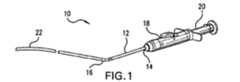
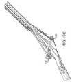
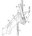
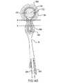
図1を参照すると、管閉鎖装置10は、一般に、近位端14と遠位端16とを有するシャフト12を備える。近位ハウジング18は、針作動ハンドル20を支持する。可撓性の非外傷性のモノレール案内体22が、シャフト12の遠位端16から遠位方向に延びている。 With reference to FIG. 1, the
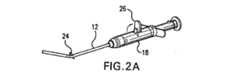
図2Aを参照してわかるように、足部24は、シャフト12の遠位端近くに連接可能に取り付けられている。足部24は、近位ハウジング18に配設された足部作動ハンドル26を作動したときに、足部が(図1に示すように)実質的にシャフト12の軸に沿って整列する低輪郭形状と、足部がシャフトから側方に延びる展開位置との間で移動する。 As can be seen with reference to FIG. 2A, the
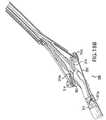
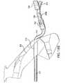
図2B〜図2Dは、変更した近位ハウジングを有する好適なプローブ10’の足部24の構造と作動を示し、また、針作動ハンドル20を押し下げることによって、針38をシャフト12から足部へ遠位方向に前進させる様式を示す。 2B-2D show the structure and operation of the
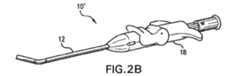
足部24の作動は、図3Aおよび図3Bにより明らかに示されている。図3Aに示す留置位置において、足部24は、実質的にシャフト12の軸28に沿って延びる。シャフトは、特に足部に隣接した箇所で幾分湾曲し得るので、シャフトの軸は、真っ直ぐである必要はないことに留意されたい。例示的実施形態では、足部24は、展開前に足部に隣接した装置の横断面を最小にするよう、実質的にシャフト12の足部レセプタクル30内に配置される。有利には、足部の展開前に、装置10は、約7Fr以下の足部24に隣接した横断面を有することができる。理想的には、シャフト12の近位端14から遠位方向に装置全体につき約6Fr以下の横断面を有する。 The operation of the
足部ハンドル26の作動は、足部作動ワイヤ32を近位方向に摺動させて、留置位置から図3Bに示す展開位置へ足部24を引っ張る。一旦展開すると、足部24の第1の端部24aと第2の端部24bは、シャフトから側方に延びる。ここでは縫合糸34は、足部の各端に隣接した針レセプタクル内に配置された端部を有する連続繊維を含む。縫合糸34の中間部分は、近位ハウジング18におよび/または近位ハウジング18を越えて、シャフト12の縫合管腔に沿って近位方向に延びることができる。別の場合には、好適なプローブ10’では、両端間の縫合糸の長さは、好適には専用の管腔内で(モノレール案内ワイヤ管腔から離れて)、可撓性の案内体22内で遠位方向に延びることができる。以下に記載されるさらに別の代替例では、短い長さの縫合糸または何らかの他の可撓性繊維は、針レセプタクル間で実質的に直接に延びてもよい。 Actuation of the foot handle 26 slides the
シャフト12は、足部位置確認管腔も含み、足部位置確認管腔は、位置確認ポート36からハウジング18の位置表示器まで遠位方向に延びる。足部が、血管内に適切に置かれると、血圧は、血液を表示器管腔を通って表示器まで近位方向に流れさせる。表示器は、任意選択で血液出口ポート、血液を見ることのできる透明なレセプタクル等を含むことができる。ある例示的な実施形態では、ハンドル18の表示器は、血液がはっきりと見えるハウジング18(図示せず)から延びるある長さの透明なチューブを含む。電気式圧力センサー、電解流体検出器等を含む、広範囲にわたる多様な代替的な位置確認センサーを使用してもよいことを理解されたい。 The
穿刺部を横切って縫合糸ループを位置決めするのに使用される構造は、図4A、図4B、図5を見れば理解できよう。一般に、針38は、シャフト12から延びて、縫合糸34に取り付けられた取り付け具40に固定係合される。さらに詳細には、針38は、凹状係合面44を定めるあご付き端部42を含む。取り付け具40は、軸方向チャンネル46を有するほぼ円筒形構造をなし、軸方向チャネル46は、針38のあご付き端部44を中に受け入れる。第1のスロットは、少なくとも1つのタブ48を限定するように、取り付け具44に切り込まれる。タブ48は、チャネル46内側へと弾性的に付勢され得る。針38が取り付け具40内に前進すると、あご付き端42は、弾性的にタブ48をチャンネル46から離れるよう変位させて、あご付き端を、取り付け具内に軸方向に入り込ませる。一旦あご付き端部42が、タブ48を越えて軸方向に配置されると、タブは、弾性的に撓んでチャンネル内に戻って、タブと凹面44との間に係合によって針38を掴む。各タブは、取り付け具を針上の所定位置に保持することができるので、2つ以上のタブを使用することで、システムの信頼性は増す。理想的には、図4Bに示すように、3つのタブが設けられる。 The structure used to position the suture loop across the puncture can be understood by looking at FIGS. 4A, 4B, and 5. FIG. In general, the
取り付け具40の縫合糸34への取り付けを簡単にするために、管状取り付け構造に切り込まれた第2のスロットが、縫合糸取り付けカラー50を定める。任意選択で、カラー50は、取り付け具40に縫合糸を機械的に取り付けるために縫合糸34周囲にかしめ付けられることができる。機械的かしめ付けに追加してかつ/またはその代わりに、縫合糸34は、接着剤、熱、留め具、結び目等を用いて、取り付け具40に結合されることができる。 A second slot cut into the tubular attachment structure defines a
取り付け具40は、かなり小さい寸法であり、一般に針経路に沿って管壁を軸方向に通って、針38と一緒に取り付け具(および取り付けられた縫合糸)を引っ込めるのを容易にする形状に作られる。針38は、一般に、約0.254mm〜約0.508mm(約0.010インチ〜約0.020インチ)の横断面幅を有する。あご42は、側方に延びて、約0.0508mm〜約0.127mm(約0.002インチ〜約0.005インチ間)の突出長さを有する係合面44を定める。取り付け具40は、針38にほぼ一致するかまたは針38よりほんの僅か大きい横断面寸法を有することが好ましい。取り付け具40は、典型的には、約0.356mm〜約0.635mm(約0.014インチ〜約0.025インチ)の外側横幅と、約0.889mm〜約1.27mm(約0.035インチ〜約0.050インチ)の軸方向長さを有する。チャンネル46は、針38の少なくとも一部を受け入れる寸法を有し、一般に約0.254mm〜約0.508mm(約0.010インチ〜0.約020インチ)の幅を有する。縫合糸34は、チャネル46の開放端の反対側で軸方向に延びて、縫合糸が針経路に沿って近位方向に引っ張られたときに、抵抗を最小にするようにすることが好ましい。例示的実施形態では、針38は、約0.508mm(約0.020インチ)の直径を有し、一方、取り付け具は、約0.508mm(約0.020インチ)の外径と、約0.406mm(約0.016インチ)の内径と、約1.19mm(約0.047インチ)の全長を有するチューブを含む。取り付け具は、典型的には、金属から成る、この例示的実施形態ではステンレス鋼から成る、弾性材を含むことが好ましい。 The fitting 40 is fairly small in size and is generally shaped to facilitate withdrawal of the fitting (and attached suture) along with the
針38は、典型的には、約127mm〜約152mm(約5.0インチ〜約6.0インチ)の長さを有し、片持ち状態で支持されているときに、約12.7mm(0.5インチ)までの距離にわたって管壁(および隣接した組織)を通して圧縮されて前進させられるのに十分な硬さを有することが好ましい。それにもかかわらず、理想的には、針は、図5を参照してわかるように、シャフト12内で側方に撓まされるのに十分な可撓性を有する。針38は、一般に高強度金属を含み、理想的にはステンレス鋼を含む。取り付け具40は、タブ48が、あご付き端42のじゃまにならないように撓み、かつ弾性的に跳ね返って凹面44に係合するように、可撓性材料から成ることも好ましい。例示的実施形態では、あご付き端部42は、約0.381mm(約0.015インチ)の直径をもち、針の直径は、凹んだ係合面を限定するように、あごから近位方向に約0.203mm(約0.008インチ)まで減少する。
概略的に上述したように、足部24は、足部の両端に隣接して針レセプタクル52を含む。取り付け具40(縫合糸34の結合される端部を有する)は、各針レセプタクル内に配置され、レセプタクル部の表面は、近位方向にかつ外方にテーパを有して、足部24が展開位置にあるとき、前進する針38を案内して取り付け具40と係合させる。取り付け具40(および縫合糸34の結合される部分)は、足部に解放可能に支持されているので、針38は、近位方向に引き込まれて、取り付け具と縫合端部を、足部から近位方向にシャフト12内に(かつ任意選択でシャフト12を通して)引っ張ることができる。例示的実施形態の針レセプタクルは、取り付け具40の中心線から20°〜35°の角度をなして外方にテーパを有し、また、取り付け具は、約0.584mm(約0.0230インチ)の直径と、約1.07mm(約0.042インチ)の長さを有する凹所内に保持される。足部の側面を通して取り付け具の凹部に至る側方開口部または窓が、プローブの組み立て中に針および/またはカフの位置決めを容易にするために設けられることができ、取り付け具凹部の近位端近傍の突出カラーは、取り付け具を所定位置に保持するのを助けることができる。 As generally described above, the
図5は、シャフト12の針案内54による針38の側方撓みも示す。この針の側方撓みによって、小さい直径のシャフトを使用することが可能となり、一方、穿刺部の対向する両側で縫合ループ内に依然として十分な組織を包囲して、ループをなした縫合糸が引き締められて固定されたとき、止血を有効に行う。例示的実施形態では、シャフト12は、ステンレス鋼、カーボン繊維、ナイロン、他の適切なポリマー等のような、生体適合性のある材料の外側ケーシングを含む。針案内54は、ナイロン、または類似物のような、ポリマー材料のケーシング内で形成された管腔として、少なくとも一部には定められ得る。ある実施形態では、シャフト12は、カーボン繊維を充填したナイロン、または別の材料を充填されたカーボン繊維を含んでよい。 FIG. 5 also shows the lateral deflection of the
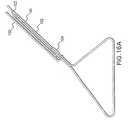
足部24の適切な構造と連接運動の一例を、図6Aおよび図6Bに示す。足部作動ワイヤ32(図3Aを参照)は、シャフト12の管腔内を進み、足部の摺動と旋回の組み合わせによって、留置位置(図6Aに示される)から展開位置(図6Bに示される)へ足部24を引っ張る。足部は、足部のいずれかの側で側方に配置したアームによって、その運動範囲全体にわたって支持されたままであり、アームは、足部レセプタクル30を(少なくとも一部)定める。一旦足部24が展開されると、針レセプタクル52および/または針レセプタクル52に配置された取り付け具は、約6.60mm〜約7.62mm(約0.260インチ〜約0.300インチ)の範囲内の横縫合幅56を定めることが好ましい。足部24は、ポリマーまたは金属から機械加工され、または鋳造され得るが、カーボン繊維を充填したナイロンなどのポリマーから成ることが好ましい。ある場合には、足部24は、後で互いに付着され得る分離した2つの半体して成形されることができる。針38は、固定した針案内54から前進し、図6Cに示すように、レセプタクル52によって横向きに取り付け具40内に向けられる。一般に超弾性状態の、Nitinol(登録商標)などの形状記憶合金は、足部24を操作するための特に有利な作動器ワイヤを提供する。 An example of a suitable structure and articulation of the
図7を参照すると、取り付け具40と縫合糸34は、針レセプタクル52から針によって近位方向に引き込められる。取り付け具40と縫合糸34を解放可能に支持し、かつ針内の縫合糸のもつれを防止するために、縫合糸34は、スロット58内にぴったり合うように受け入れられ、このスロット58は、針レセプタクル52から側方に延びている。針は、針レセプタクル52から軸方向に取り付け具を引っ張るので、縫合糸34は、スロット58から引っ張られ、かつ足部24から離れるよう引っ張られる。縫合糸スロット内で近位方向に縫合糸を曲げることは、また、局所的に縫合糸幅を増すことができるので、曲がった縫合糸とスロットとの間の相互作用は、取り付け具を凹所内に保持するのを助けることができる。 Referring to FIG. 7, the fitting 40 and
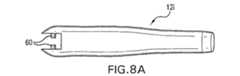
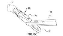
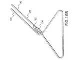
幅広い種々の足部作動機構は、本発明の範囲内で使用することができる。第1の代替例としての足部作動装置は、図8A〜図8Cに示されている。この実施形態では、シャフト12iは、ピン60を有し、このピン60は、足部24iの結合されるスロット62内にある。作動ワイヤの近位方向運動は、足部24iを軸方向および回転方向に動かし、ピン60はスロット62に沿って摺動し、足部はピンの回りに旋回する。この実施形態では、案内体22は、図8Cに示すように直接足部から延びる。 A wide variety of foot actuating mechanisms can be used within the scope of the present invention. A first alternative foot actuating device is shown in FIGS. 8A-8C. In this embodiment, the
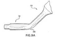
さらに別の足部作動機構を、図9Aおよび図9Bに示している。この実施形態では、摺動可能な足部24iiは、摺動してシャフト12iiのレセプタクル30に受け入れられる。図9Aの留置位置から図9Bの展開位置までの足部24iiの摺動は、足部を旋回させずに、針レセプタクル52をシャフト12iiから針の経路内に置く。案内体22(図1を参照)は、ここでは、シャフトからある固定した角度をなしてシャフト12iiの遠位端から延びる。任意選択で、組織領域を通しての挿入は、多くの実施形態で、案内体に隣接したシャフト軸に追加の湾曲部を含むことによって簡単になすことができる。 Yet another foot actuation mechanism is shown in FIGS. 9A and 9B. In this embodiment, the slidable foot 24ii is slid and received in the
さらに別の足部作動機構は、図9Cおよび図9Dを参照して理解することができる。シャフト12iiiは、2つの部分で形成され、それら部分は、オフセットクランク装置を使用して、足部作動レバー26iiiが動いたとき、相互に対して軸方向に摺動する。同様のオフセットクランクが、足部24iiiを支持するので、摺動シャフト部分が、図示のように足部を旋回させる。 Yet another foot actuation mechanism can be understood with reference to FIGS. 9C and 9D. The shaft 12iii is formed of two parts that slide axially relative to each other when the foot actuating lever 26iii is moved using an offset crank device. A similar offset crank supports the foot 24iii so that the sliding shaft portion pivots the foot as shown.
針が取り付け具に向けられているとき、縫合糸中の針のもつれを防止するために、多様な特徴が、連接運動可能な足部、針レセプタクル、および/または針に含まれ得る。図10Aに示すように、可動のフラップ64が、スロット58にわたって延び、その結果、前進する針は、スロットに入り縫合糸に直接係合するのではなく、取り付け具に向かってフラップに沿って摺動することができる。フラップ64は、スロットの一方の側に沿って付着されることができ、フラップの他方の側は、取り付け具と縫合糸が針によって引き込められたとき、スロット58から縫合糸を解放するためにレセプタクル内で撓んでいる。 Various features can be included in the articulatable foot, needle receptacle, and / or needle to prevent entanglement of the needle in the suture when the needle is directed toward the fitting. As shown in FIG. 10A, a
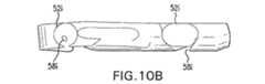
縫合糸との針のもつれを防止するための別の機構を、図10Bに示す。この実施形態では、針レセプタクル52iは、接線方向スロット58iをもち、接線方向スロット58iは、レセプタクルの表面に実質的に接線方向に延びている。この接線方向構成の結果、レセプタクル52iに入る針は、その中に含まれている取り付け具に向くが、一般に縫合糸ともつれるように、接線方向スロット58i内に入って進むことはできない。この実施形態に示すように、スロットは、任意選択で足部を側方に通って延びて、縫合糸のループが、妨害なしにシャフトの一方の側から引かれることができる。 Another mechanism for preventing needle entanglement with the suture is shown in FIG. 10B. In this embodiment, the needle receptacle 52i has a
縫合糸と針との間のもつれを防止するためのさらに別の機構を、図10Cおよび図10Dに示す。2部分構成の針38iは、外側シース66と内側コア68とを含む。これらの針の部分は、最初は、一緒に受容部内へ進み、針コア68は引き込められて、図10Cに示すように、針は滑らかなテーパ端部を呈する(組み合わされた先端は、縫合糸を含むスロットより大きい直径を有することが好ましい)。一旦、2部分構成の針38iが、針レセプタクル内に完全に位置すると、針コア68は軸方向に延びて、あご付き先端部42と凹状係合面44を露出させ、針レセプタクル内の取り付け具に針を固定することができる。図4Aおよび図5の実施形態では、あご付き先端部42は、針構造の残りの部分と一体に作られるが、この先端は、縫合糸34を含む径方向スロット58より大きい横断面を有する。その結果、あご付き先端部は、スロットに入ることはできず、それによって針と縫合糸とのもつれを防止する。 Yet another mechanism for preventing tangles between the suture and the needle is shown in FIGS. 10C and 10D. The two-
別の管閉鎖プローブ70を、図11A−1〜図11Eを参照して説明する。この実施形態は、前述のように、1対の針レセプタクル52を有する連接運動可能な足部24を含む。各針レセプタクル52は、可撓性接続繊維74が結合される針の先端に連結するための取り付け具40を含んでいるが、この場合、接続繊維74は、図11A−1に仮想線で概略的に示すように、ある一時的な接続繊維を含む。この接続繊維は、直接針レセプタクル間に跨る。延びたループの両端を、針経路を通してそして結び用の組織領域の外に近位方向に引っ張るのではなく、閉鎖システム70は、穿刺部を横切って1つの針経路に沿って遠位方向に、次に他の針経路に沿って近位方向に、縫合糸の単一の端部を進める。この相互作用をもたらすために、少なくとも1つの針は、縫合糸34を、ここでは少なくとも1つの針に担持された着脱可能な結合構造の形の接続繊維74に取り付けるための手段を含む。この構造は、予め結んだ結び目の使用を容易にする。 Another
図11A−1および図11Bを参照すると、プローブ70の遠位端は、皮膚Sを遠位方向に通って患者の組織T内に進入し、プローブは、プローブ軸に沿って整列した足部24をもつ小さい輪郭形状にある。しかし、ここでは縫合糸34の端部76は、中空針38’の着脱可能な針先端78に取り付けられている。着脱可能な先端78は、取り付け具を含み、この取り付け具は、(針38のあご付き針端部と同様の)あご付き針端部に取り付けられた、取り付け具40と同様の縫合糸の端部を受け入れる開口部を有する。縫合糸34は、針がその長さに沿って開放したチャンネルを有する中空針38内で近位方向に延びることができ、着脱可能な先端78から近位方向に中空針を出ることができ、または固体針と並んで配置され得る。針38(中空針38’の反対側の)は、上記のように固定したあご付き先端を有し、縫合糸のバイト部80は、解放可能にプローブシャフトに取り付けられ、固定された先端針の針案内54の開口部を包囲する。縫合糸のバイト部は、プローブのスロット内に解放可能に配置されることができ、弱い接着剤または被覆等によって所定位置に一時的に保持され得る。縫合糸34の第2の端部82は、プローブのシャフトに沿って近位方向に延び、縫合糸の第2の端部も、任意選択でシャフトに沿って解放可能に保持される。 Referring to FIGS. 11A-1 and 11B, the distal end of the
バイト部80は、図11A−2と図11A−3を参照すれば理解できるように、第1の端部の縫合糸がバイト部を通過するとき、結び目を定める。バイト部80は、多くの場合、2つ以上のループを含み、角結び(図11A−2に概略示したレイアウトを用いて)、クリンチ形の結び(図11A−3)、または多様な知られているあるいは新しい外科用の結び目を定めるように、予め配置され得る。 The
プローブ70は、組織領域TTに沿って血管V中の穿刺部Pに進む。一旦、足部24が、血管V内に配置されると、引っ張りワイヤが、足部を近位方向に動かし、足部を横に旋回させて、図11Bに示すように、足部が管の軸Aに沿って延びる。次に、針レセプタクル52が適切に位置決めされることを保証するために、足部が、管壁Wの内面に対して近位方向に引っ張られ得る。 The
図11Cおよび図11Dを参照して理解されることができるように、中空針38’と針38は、レセプタクル52内の取り付け具40に係合するよう進む。中空針38’は、管壁Wを通して遠位方向に縫合糸34の第1の端部76を引っ張り、着脱可能な先端78は、上記のあごおよびタブの相互作用を用いて、結合される取り付け具40内に固定される。接続繊維74は取り付け具40の間に延び、かつ針が引き込められたときに、着脱可能な先端78は中空針38’から引き離されることができるので、これは、針38を縫合糸34の第1の端部76に有効に結合する。着脱可能な先端は、中空針内に部分的にあり(逆もまた同様であり)、その結果、アセンブリは、圧縮下で共に留まる。それ故、針38は、図11Dに示すように、穿刺部Pを横切って、中空針38’によって形成された針経路に沿って遠位方向に、および針38によって形成された針経路に沿って近位方向に縫合糸を引っ張ることができる。 As can be understood with reference to FIGS. 11C and 11D, the
図11Dおよび図11Eは、結び目が、バイト部80を通して近位方向に、針38、接続繊維74、および縫合糸34の第2の端部76を(取り付け具40と着脱可能な針先端78と一緒に)引っ張ることによって、完成することができることを示す。縫合糸34の第2の端部82は、バイト部80から引き離されることができ、縫合糸の両端は、締められ、プローブは永続する止血を提供するために除去され得る。 11D and 11E show that the knot is proximally through the
プローブ70の除去は、第1の端部76をプローブの外面上でバイト部80に結合することによって、かつ縫合糸34と中空針38’を以下のように配置することによって、容易にされ得ることを理解されたい。すなわち、着脱可能な先端78が、例えば、針が縫合糸を包囲しないように、縫合糸が、先端へ延びるチャンネルを通して先端から近位方向に針を出るようにすることによって解放されたときに、縫合糸が、針から引き離されることができるような配置である。このような準備を含むことによって、足部24が狭い形状に戻った後、プローブは、所定位置で予め結ばれた結び目を出て、組織領域から近位方向に引かれることができる。 Removal of the
代替的な装置(プローブ70の着脱可能な針端を使用する)は、管穿刺部の閉鎖のために、予め結ばれた結び目等の利益を提供することができる。例えば、各針が着脱可能な先端を含んだ1対の針を有するプローブが、バイト部を通して第1の端部76を引っ張るために使用され、その結果、バイト部は、1つの針の針経路を包囲する必要がなくなる。 An alternative device (using the removable needle end of probe 70) can provide benefits such as pre-knotted knots for closure of the tube puncture. For example, a probe having a pair of needles, each including a detachable tip, is used to pull the
ある場合には、特に大きい穿刺部を閉鎖するために、平行に「X形」パターンまたは類似形をなすように、穿刺部を横切って複数の縫合糸ループを提供するのが有利であり得る。図12Aおよび図12Bに示すように、本発明は、3つ以上の針、および結合されるレセプタクル、取り付け具、縫合糸等の使用を包含する。多数のループシステムは、4個、6個、8個以上の針を有することができるか、または特に、1つまたは複数の取り付け具がそこから延びる複数の縫合糸端部を有する場合には、奇数の針と取り付け具を有することさえもできる。これによって、幅広い多様な縫いパターンが、そのような多数のループプローブによって提供されることを可能にする。 In some cases, it may be advantageous to provide a plurality of suture loops across the puncture to form an “X” pattern or similar in parallel, particularly to close a large puncture. As shown in FIGS. 12A and 12B, the present invention encompasses the use of more than two needles and associated receptacles, fittings, sutures, and the like. Multiple loop systems can have 4, 6, 8 or more needles, or particularly when one or more attachments have multiple suture ends extending therefrom. You can even have an odd number of needles and fittings. This allows a wide variety of sewing patterns to be provided by such a large number of loop probes.
図1〜図7のプローブの使用方法は、図13A〜図13Gを参照すれば理解できよう。血管Vにアクセスした後(多くの場合Seldinger技術を使用して)、案内ワイヤGWは、皮膚S内にかつ組織領域TTに沿って組織Tを通して下方へ延びたままに置かれる。案内ワイヤGWは、管壁W中の穿刺部Pを通して管Vに入り、多くの脈管内処置の間、管に沿って延びる。図13Aに示すように、遠位案内体22は、モノレール様式で案内ワイヤGW上を前進し、その結果、案内ワイヤは、組織領域TTに沿ってかつ穿刺部Pを通して管内にプローブを方向付けるのを助ける。図13Bは、センサー36が管内に配置されたとき、足部24が展開のために十分な距離にわたって進められたことを、オペレータに知らせるために、血液が、センサーポートからシャフト12内の管腔を通して近位ハンドルまで流れることができることを示す。 The use of the probe of FIGS. 1-7 can be understood with reference to FIGS. 13A-13G. After accessing the blood vessel V (often using the Seldinger technique), the guide wire GW is placed extending down through the tissue T in the skin S and along the tissue region TT. Guide wire GW enters tube V through puncture P in tube wall W and extends along the tube during many intravascular procedures. As shown in FIG. 13A, the
足部の展開は、図2Aおよび図2Cを参照して上述し例示したように、足部展開ハンドルの作動によって行われる。上記のように、案内体22は、プローブを管Vの軸と整列させるのを助ける。特定の管アクセス技術により整列を助けるのに適するように、案内体22は、シャフト12に対してある角度をなしてかつ/またはオフセットして設定されることができる。図13Cに示すように、展開された足部24はシャフトから横に延び、その結果、レセプタクル52に隣接した足部24は、シャフト12を穏やかに引っ張ることによって、管壁Wに対して引き上げられることができる。故に、足部は、管壁から或る距離の箇所に針案内54を精密に位置決めするのを助ける。 The foot deployment is performed by actuation of the foot deployment handle, as described and illustrated above with reference to FIGS. 2A and 2C. As described above, the
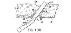
図13Dを参照すれば、可撓性針38は、展開された足部のレセプタクル52に向かって針案内54によって横に撓まされる。その結果、針は、針作動ハンドル20が押されたとき(図2Dを参照)、遠位方向にかつ横に片持ち状に前進し、レセプタクル52のテーパ表面は、組織Tまたは管壁Wによって針の偶発的な撓みを克服するように、針を押し戻して取り付け具と整列させることを助ける。これによって、針38は、レセプタクル52内の取り付け具40にしっかり係合し、それにより、縫合糸34の端部を針に結合することが保証される。縫合糸34は、図では、シャフト12の側面に沿って、足部レセプタクル30の外側で案内体22内の管腔まで延びているが、その代わりに、縫合糸ループは、シャフト12の管腔内で近位方向に延び、足部および/または足部レセプタクルを通る経路を定められ、かつ/または足部24に隣接したスプールに格納されることを理解されたい。いずれにせよ、縫合糸34は、穿刺部Pを横切る連続ループを形成するために、その両端間でプローブから引き離されることができるべきである。 Referring to FIG. 13D, the
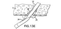
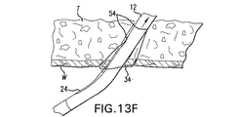
図13Eおよび図13Fを参照すれば、取り付け具40と縫合糸34の両端は、針38によって形成された針経路に沿って管壁Wを通して近位方向に引っ張られる。任意選択で、針は、組織領域の外にシャフト12を離れるように近位方向に引き込められることができ、またはそれら針は、針案内54内でシャフトに結合されたままでいることができる。足部作動器は、シャフト12に沿って足部24を格納するように動かされ、次にシャフトは、組織領域から近位方向に引かれることができる。軟質の可撓性のポリマーからなることができる案内体22は、一時的に、少なくとも部分的に組織領域TT内へかつ穿刺部Pを通して延びて、ループが固定されるまで、血液の損失を減らすのを助けることができる。 Referring to FIGS. 13E and 13F, both ends of the
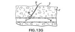
ここで図13Gを参照すると、一旦、シャフト12が、針案内54を露出するのに十分に引き込められたら、縫合糸ループの両端は、オペレータによって掴まれることができる。次に縫合糸34に結び目を結ぶことは、従来の方法で行うことができる。クリンチ形の結び目を使用することにより、案内体22を除去する間に、結び目を徐々に締めることを容易することができるが、幅広い多様な結び目および結び目の前進させる技術を、使用することができる。 Referring now to FIG. 13G, once the
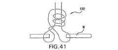
図14Aおよび図14Bは、管閉鎖装置100のある実施形態を示している。この実施形態は、(以下に記載の)1対のペネトレータレセプタクルを有する連接可能な足部114(図14B)を含む。各ペネトレータレセプタクルは、結合されるペネトレータの先端に可撓性繊維を結合する取り付け具(またはカフ)を含むが、この場合繊維は、ペネトレータレセプタクル間に直接及ぶ連結部112などの長さの短い縫合糸であってよい。針経路を通してかつ組織領域の外に近位方向に、延ばされたループの2つの端部を引っ張って結ぶのではなく、閉鎖システム100は、縫合糸の単一の端部を、1つの針経路に沿って遠位方向に、穿刺部を横切って、次に他の針経路に沿って近位方向に進める。この相互作用をもたらすために、少なくとも1つの針は、本明細書では少なくとも1つの針に担持された着脱可能な結合構造体の形態で、縫合糸102を連結部112に取り付ける手段を含む。この構造は、予め結んだ結び目の使用を容易にする。 14A and 14B show an embodiment of the
図15Aは、足部114の展開前の位置にある装置100の側面断面図を示す。装置100は、動脈壁W内の切開部105を通って前進されている。わかり易いように、参照符号122は、装置の前方側を示し、参照符号124は、装置の後方側を示す。装置100は、剛性のあるシャフト118を有し、このシャフト118は、細長いボディまたはペネトレータ106および106’を運ぶために、内に画定されたチャネルを有する。ペネトレータ106’は、前方ペネトレータと呼ぶこともでき、ペネトレータ106は、後方ペネトレータと呼ぶことができる。限定するものではなく説明のために、前方ペネトレータ106’は、予め結んだ結び目104を運び、後方ペネトレータ106は、着脱可能な結合構造体またはペネトレータ先端108を運ぶ。前方ペネトレータ106’は、その遠位端にてペネトレータ先端108’を定める。 FIG. 15A shows a side cross-sectional view of
連接可能な足部114は、前方および後方ペネトレータレセプタクル116’および116をそれぞれ含む。これらのレセプタクルは、カフポケットとも呼ばれる。カフポケット116’および116内に位置決めされたカフ110が示されている。連結部112は、カフ110間で延びる。 The
図15Bは、カフポケット116を位置決めして、第1のペネトレータ106’および第2のペネトレータ106を受け取るように展開された足部114を示す。図15Bに示すように、前方ペネトレータ106’は、その長さの近位部分周囲に配設された予め結んだ結び目104を有する。別の場合には、予め結んだ結び目104は、結び目チューブの周縁部周囲に配置されてもよく、(以下に詳細に記載するように)前方ペネトレータ106’は、その結び目チューブ内を通過することができる。 FIG. 15B shows the
図15Bは、本発明のある実施形態による管腔107内に展開された縫合装置100を示す。この図を参照してわかるように、縫合装置100は、ペネトレータ先端108’を有する細長いボディ106’を含む。細長いボディ106および106’は、展開されて管壁W内に貫通部109および109’を形成する。ペネトレータ先端308の構成によって、直ちに切開部105を囲繞する管壁Wの貫通部は、貫通部309を形成することを可能にする。このようにして、ペネトレータ先端108が組織壁Wを貫通することによって、細長いボディ106が組織を通過して管腔107内に入ることを可能にする。細長いボディ106が、切開部105に直近の組織壁Wを通過して足部114に入るので、細長いボディ106は、縫合糸102を保持する。 FIG. 15B illustrates the
図15Bを参照してわかるように、この実施形態では、足部114は、カフ110および110’が、縫合装置100および足部114の両側に配設される単一ユニットデザインを有する。この向きによって、細長いボディ106および106’の展開中に力の釣り合いを取ることが可能となり、これによって切開部105を正確に縫合すること、および不正確に縫合する可能性を最小化することが可能となる。また、この図を参照してわかるように、縫合装置100は、管腔107に対して長手方向に縫合糸を送り、これにより動脈径の収縮は最小化される。同様に、この実施形態では、足部114は、縫合装置100のシャフト118に対して角度「Q」で位置決めされている。角度「Q」は、約20°〜約60°の範囲であることが好ましく、約40°であることがさらに好ましい。この角度「Q」は、大腿動脈にアクセスするのに一般に用いられる穿刺角度に近い。角度Qおよびシャフト118の剛性特徴は、前方ペネトレータおよび後方ペネトレータの両方によって、正確で実質的に同時的な「カフ捕捉」を提供するように働く。さらに、装置100は、導入器シースなしに使用されるのが好ましいので、シャフト118の剛性性質は、ペネトレータが遠位方向に動いてカフと係合するときに、ペネトレータの移動制御を提供する。したがって、装置100は、既存の組織領域を乱さず、かつ患者に過度の不快感を与えることなく、同じ大腿動脈アクセス穿刺に用いることができる。 As can be seen with reference to FIG. 15B, in this embodiment, the
細長いボディ106および106’、ならびに縫合糸102の両方が、管腔壁Wを通って管腔107に入るとき、細長いボディ106および106’は、足部114と係合する。細長いボディ106および106’のペネトレータ先端108および前方ペネトレータ先端108’は、足部114のカフ110および110’と係合する。カフ110および110’は、カフ110および110’を相互に接続する連結部112を含む。カフ110および110’は、ペネトレータ先端108および前方ペネトレータ先端108’が、連結部112を介して相互に結合されるように、ペネトレータ先端108が前方ペネトレータ先端108’に接続されるのを容易にすることに留意されたい。 As both
図16Aおよび図16Bは、予め展開された状態(図16A)および展開された状態(図16B)の縫合糸のバイト部を示している。縫合糸102は、組織壁へと送られる前に保管される装置のシャフトから下方向に自動的に移動する、予め結んだ結び目104を提供するように配置される。縫合糸102のループ104は、展開中に縫合糸のレール部分140に結び目104を押し下げるように働く。オペレータが正しい端部を引っ張って結び目を進められるように、展開中に、縫合糸102の端部140および150を識別するようにできることが好ましいであろうことを理解されたい。非レール端部が引っ張られる場合、結び目が管の壁のその展開位置に進められる前に、結び目が早過ぎて締められるかもしれない。 16A and 16B show the bite portion of the suture in a pre-deployed state (FIG. 16A) and a deployed state (FIG. 16B). The
縫合糸の両端は、(例えば、染料を用いて)その一端の色を変えること、一端にアタッチメント(例えば、収縮包装チューブ、ビード等)を提供すること、または縫合糸自身を用いて(例えば、一端に結び目を作ること)、識別されることができる。 Both ends of the suture can change color at one end (eg, using a dye), provide an attachment (eg, shrink wrap tube, bead, etc.) at one end, or use the suture itself (eg, Making a knot on one end), can be identified.
図15Cは、カフ110内に完全に展開されて、カフ110と係合したペネトレータ先端を示している。図15Dは、先端がカフ110と係合した後に、引っ込められたペネトレータを示している。前方側122では、ペネトレータ106’は、前方カフ110を遠位方向に引っ張っている。後方側124では、ペネトレータ先端108は、以下に記載の機構を用いてペネトレータ106から分離されている。図15Dに示すように、ここでは連結部112は、後方カフ110を介して縫合糸の一端に結合されている。ペネトレータシャンク側の開口部を介して、後方ペネトレータシャンクを出て行く縫合糸102も示している。 FIG. 15C shows the penetrator tip fully deployed in the
図15Eを参照すると、足部114の展開後、縫合糸102は、方向矢印X1で示したように動く。縫合糸102が動くと、縫合糸ループ103も、方向矢印X2で示した方向に足部114および切開部(図示せず)に向かって動く。縫合糸102は、足部114を通って、および縫合糸保持表面111を定める足部114から遠位にある開口部を通って移動する。この実施形態では、縫合糸保持表面111は、足部114から離れた縫合装置100の遠位端に配設されている。縫合糸保持表面111は、縫合中に縫合糸102にかかる力に耐える。このようにして、縫合糸保持表面111は、切開による引っ張りの間に切開部にかかる力を最小化し、これにより、直ちに切開部を囲繞する組織に損傷が及ぶ可能性を最小化する。この実施形態では、縫合糸保持表面111は、縫合装置100の遠位端に配設されたスロットであり、図15Eに関して示した切開部縫合中の縫合糸102用の通路を含む。 Referring to FIG. 15E, after deployment of
縫合糸ループ103および縫合糸102が動くにつれて、予め結んだ縫合糸の結び目104も、足部114および切開部に向かって縫合糸ループ103と同じ方向に動く。縫合糸102および予め結んだ縫合糸の結び目104が、動脈壁に形成された切開部を縫合するまで、縫合糸ループ103は、切開部に向かって予め結んだ縫合糸の結び目104を動かし続ける。縫合糸切断器を用いて、動脈切開部への結び目104の送りを支援することもできることを留意されたい。縫合糸切断器は、動脈切開部に向かって結び目を押し、かつ結び目が一旦締められたら、結び目104の直近で縫合糸を切るのに適した任意の装置であってよい。 As the
ここで図15Fを参照すると、縫合装置100は、予め結んだ縫合糸の結び目104を切開部まで送り、足部114は、その展開されていない位置まで戻されている。ペネトレータ(図示せず)は引っ込められ、連結部は、完全に結び目を通って完全に引っ込められ、結び目は、動脈壁近傍まで進められている。装置のボディが除去されるとき、ステッチは、動脈の切開部を横切って適所に留置する。本願明細書に記載の装置の実施形態は、脈管の横方向の収縮を最小にするように、かつ脈管組織の繊維の横方向を利用するように、脈管に対して長手方向に縫合糸のステッチを置くことを留意されたい。 Referring now to FIG. 15F, the
図16Aおよび図16Bは、予め展開された状態(図16A)および展開された状態(図16B)の縫合糸のバイト部を示している。縫合糸102は、組織壁へと送られる前に保管される装置のシャフトから下方向に自動的に移動する予め結んだ結び目104を提供するように配置される。縫合糸102のループ104は、展開中に縫合糸のレール部分140に結び目104を押し下げるように働く。オペレータが正しい端部を引っ張って結び目を進められるように、展開中に縫合糸102の端部140および150を識別するようにできることが望ましいことを留意されたい。非レール端部が引っ張られる場合、結び目が、管の壁のその展開位置に進められる前に、結び目が早過ぎて締められるかもしれない。 16A and 16B show the bite portion of the suture in a pre-deployed state (FIG. 16A) and a deployed state (FIG. 16B). The
端部は、(例えば、染料を用いて)その一端の色を変えること、一端にアタッチメント(例えば、収縮包装チューブ、ビード等)を提供すること、または縫合糸自身を用いて(例えば、一端に結び目を作ること)、識別することができる。 The end can change color at one end (eg, using a dye), provide an attachment (eg, shrink wrap tube, bead, etc.) at one end, or use the suture itself (eg, at one end) Make knots), can be identified.
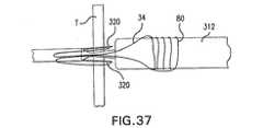
図17Aは、縫合装置300の一実施形態の足部の後方部分を拡大した詳細を示す。本発明のある実施形態によれば、細長いボディ306は、動脈、血管等の管腔の壁を貫通することのできる任意のタイプの構造体であり得る。この貫通能力に加えて、細長いボディ306は、縫合糸を保持することのできる中空管であり得る。そのような構造体の例には、皮下針等を含み得る。縫合装置300は、そのシャフト(図示せず)内に細長いボディ306を格納する。図2B〜図2Dに関して先に述べたように、使用者は、縫合装置300のハンドル(図示せず)を展開し、これにより細長いボディ306およびペネトレータ先端308が展開される。以下の図17Bを参照して示すように、展開中、細長いボディ306およびペネトレータ先端308は、直ちに切開部305を囲繞する管腔壁Wを貫通し、患者の管腔307に入る。 FIG. 17A shows an enlarged detail of the posterior portion of the foot of one embodiment of the
一旦、ペネトレータ先端308が、カフ310と係合すると、細長いボディ306およびペネトレータ先端308は、カフ310と共に足部314を通って進んで、管腔307に入る。図17Bを参照してわかるように、カフ310が、ポケット316から押し出されて足部314を通って管腔307に入るように、カフ310は、足部314を押し通される。図17Cに関して示すように、一旦、カフ310および細長いボディ306が、管腔307に入ると、ペネトレータ先端308は、プッシュマンドレル315を介して細長いボディ306から分離する。 Once the
図17Cは、本発明の一実施形態による細長いボディ306からのペネトレータ先端308の分離を示している。ペネトレータ先端308がカフ310と係合すると、ペネトレータ先端308の近位面308bと接触するように、かつさらにはペネトレータ先端308が細長いボディ306から分離するまで、プッシュマンドレル315は、さらに前進される。図17Dに関して示すように、ペネトレータ先端308が細長いボディ306から分離すると、プッシュマンドレル315および細長いボディ306は、足部314から引っ込む。 FIG. 17C illustrates the separation of the
図17Dに示すように、ペネトレータ先端308が、細長いボディ306から分離した後、細長いボディ306は、ペネトレータ先端308およびカフ310から引っ込む。一方、装置の前方側(図17Dには示さず)では、細長いボディ306’も、図15Cに関して先に記載したようなカフ310’と係合する針先308’を含む。針先308’は、カフ310’と係合すると細長いボディ306’から分離しない。したがって、細長いボディ306’が管腔307内から引っ込む間、針先308’も、貫通部309’を通って管腔307から引っ込む。針先308’が、貫通部309’を通って引っ込むので、細長いボディ306’も、カフ310’を引っ込める。先に記載したように、カフ310’は、連結部312を介してカフ310と結合する。カフ310’が貫通部309’を通って引っ込む間、カフ310および縫合糸302も、貫通部309’を通って引っ込み、これにより縫合糸302は、貫通部309’を通って引かれる。図18Aに関して示したように、足部314は、縫合装置300の操作中に、縫合糸302用の縫合糸保持表面を提供することができることを留意されたい。 After the
図18Aは、管腔307ならびに通路309および309’を通る縫合糸302の通路を図示する本発明のある実施形態を示す。この図を参照してわかるように、足部314のカフポケット316は、縫合糸302が通路を通って引き出されるときに、縫合糸302用の縫合糸保持表面を提供する。足部314の縫合糸保持表面は、縫合糸302が切開部305を囲繞する組織を損傷させる可能性を最小化する。 FIG. 18A shows an embodiment of the present invention illustrating the passage of
図18Bに示した別の実施形態では、縫合装置300は、縫合糸302に縫合糸保持表面も提供する。細長いボディ306および306’が管腔307から引っ込む間、縫合糸302は、足部縫合糸保持表面314aおよび足部から遠位に形成された縫合糸保持表面311を通って引っ込む。細長いボディ306および306’が管腔307から引っ込む間に、縫合糸302が患者に損傷を及ぼす可能性を最小にするために、遠位にある縫合糸保持表面311および足部縫合糸保持表面314aは、縫合糸302を誘導する。この実施形態では、縫合糸保持表面311は、足部の遠位にある装置の本体に形成されたスロットである。このスロットは、連結部および縫合糸用の通路と縁部311aとを含む。縁部311aは、動脈の切開部の縁部と接触し、血管の外膜上に引っ掛かる可能性があることも予想される。装置が切開部を通して挿入されるとき、スロットおよび縁部311aにわたる滑らかな移行を提供する、フラップ、Oリング等の種々の装置が提供され得る。 In another embodiment shown in FIG. 18B, the
図19Aおよび図19Bは、足部314からカフ310を解放する本発明の代替的な実施形態を示している。この実施形態では、足部314は、連結部312が通過する連結通路313を含む。細長いボディ306が、ペネトレータ先端308をカフ310と係合させた後、足部314から引っ込む間に、細長いボディ306は、足部314からカフ310およびペネトレータ先端308を除去する。細長いボディ306にペネトレータ先端308を保持する力は、カフポケット316内でカフ310を保持する力を上回る。一旦、カフ310が、足部314を除去し、かつ図19Bに関して示した方向を達成すると、前述されたプッシュマンドレル(図示せず)は、細長いボディ306からペネトレータ先端308を分離する。ペネトレータ先端308が細長いボディ306から分離すると、連結部312は、カフ310およびペネトレータ先端308と共に、連結部312および細長いボディ306’を介して通路313を通って引っ込む。別の実施形態では、カフ310およびペネトレータ先端308は、連結部312の張力によって細長いボディ306から引き離され得る。 19A and 19B illustrate an alternative embodiment of the present invention for releasing the
図20A〜図20Cに示したさらに別の代替的実施形態では、カフ310およびペネトレータ先端308は、カフポケット316から除去される前に、細長いボディ306から分離され得る。この実施形態では、図20Cに示したように、細長いボディ306およびペネトレータ先端308がカフ310と係合した後、プッシュマンドレル315は、細長いボディ306からペネトレータ先端308を分離させて、連結部312の張力によって除去されるカフポケット316内にペネトレータ先端を残す。 In yet another alternative embodiment shown in FIGS. 20A-20C, the
他の方法を用いて、細長いボディ306からペネトレータ先端308を分離することもできることに留意されたい。これらの方法には、限定するものではないが、摩擦または張力を利用した分離がある。図20Bを参照すると、カフポケット316とカフとの間の摩擦が、細長いボディ306からのペネトレータ先端308の分離を生じさせる実施形態では、ペネトレータ先端308の表面308cは、カフポケット316のカフ表面316aと摩擦係合する。細長いボディ306が足部314から引っ込む間、カフ表面316aとペネトレータ先端表面308cとの間の摩擦係合によって、ペネトレータ先端308は細長いボディ306から分離される。連結部張力が、細長いボディ306からペネトレータ先端308を分離させる実施形態では、連結部312が、カフ310と310’との間で引っ張られるように、連結部312は張られる。このようにして、連結部312の張力によって、細長いボディ306が足部314から引っ込む間に、カフ310が細長いボディ306と共に足部314から外れることが阻止されるので、ペネトレータ先端308はカフ310から分離される。 It should be noted that other methods can be used to separate the
分離後、細長いボディ306および細長いボディ306’(図示せず)が引っ込む間に、連結部312は、カフポケット316からカフ310およびペネトレータ先端308を引き出すことができる。先に記載したように、カフ310’は、細長いボディ306’と係合し、細長いボディ306’が管腔307から引っ込むときに、連結部312を介してカフ310を引っ張る。このようにして、図20Cに関して示したように、連結部312が引っ込むことで、カフ310が引っ張られ、これによって、カフポケット316から管腔307を通して縫合糸302と共にカフ310が引っ張られる。 After separation,
図21は、結び目チューブ301の周縁部周囲に配設された予め結んだ縫合糸の結び目304を示す。この実施形態では、結び目チューブ301は、縫合装置300が切開部を縫合するときに、細長いボディ(図示せず)が通過できるように構成された中空の中央部301aを含む。しかし、本発明の別の実施形態では、細長いボディ(図示せず)は、縫合糸302を格納してもよいことを留意されたい。別の実施形態では、縫合糸302および予め結んだ縫合糸の結び目304は、予め結んだ縫合糸の結び目304が細長いボディのポケット(図示せず)内に存在し得る細長いボディの周縁部周囲に配設される。 FIG. 21 shows a
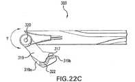
図22A〜図22Cに関して示したように、本発明の縫合装置の実施形態は、足部用の付加的な構成も含んでよい。この実施形態では、縫合装置300は、カフポケット319aおよび319bを有する足部319を含む。このカフポケット319aおよび319bの構成によって、足部319が縫合装置300の使用中にカフ310および310’を保持することが可能となる。足部は、図22Aに関して示した第1の方向から、図22Bに関して示した第2の方向に、図22Cに示したヒンジ320を介して旋回する。 As shown with respect to FIGS. 22A-22C, embodiments of the suturing device of the present invention may also include additional configurations for the foot. In this embodiment, the
図22Cは、ヒンジ320を示しており、このヒンジ320は、方向矢印Yによって示した方向への足部319の回転を可能にする。ヒンジ320は、足部319を縫合装置300に回転可能に結合させることのできる、ピンアセンブリ等の任意のデバイスであってよい。ヒンジ320に加え、足部319は、カフ310および310’を相互に結合させるコネクタ322を含む。コネクタ322が足部314の通路317内にあるので、コネクタ322も、コネクタ322の屈曲を可能にする可撓性部分322c(図22Cに関して示した)を含む。このコネクタは、細長いボディ306’および306のペネトレータ先端308および針先308’の接続を容易にする、端部322aおよび322bも含む。 FIG. 22C shows a
縫合装置300が足部319を使用する本発明のある実施形態では、縫合装置300の使用中、縫合装置300が管腔307内に挿入されると同時に、使用者は、図22Aに関して示したような足部319を展開する。足部319が展開されると、使用者は、先に記載したように、カフ310(図示せず)と係合する細長いボディ306(図示せず)を展開する。一旦、ペネトレータ先端308が、プッシュマンドレル315を介するか、または先に記載した他の手段を介して細長いボディ306から分離すると、使用者は、足部319を回転させて図22Bに関して示した方向にする。図22Bに関して示した足部319の方向になると、使用者は、カフ310’(図示せず)と係合する細長いボディ306’(図示せず)を展開する。細長いボディ306’が、カフ310’と係合した後、使用者は、細長いボディ306’をカフ310および310’ならびに縫合糸302と共に引っ込めて、先に記載したように切開部を縫合する。 In certain embodiments of the invention in which the
縫合装置300の別の実施形態は、図23Aに関して示したような足部324および328を含む。図23Aは、縫合装置300が足部324および328を含む本発明のある実施形態を示している。図23Bを参照してわかるように、縫合装置300が管腔307内に挿入および引き込める間に、足部328が足部324内に収まるように、足部324は中空である。足部324および328は、カフポケット324aおよび328a、ならびにカム表面324bおよび328bも含む。カフポケット324aおよび328aの構成によって、縫合装置300の使用中に、カフ310および310’を足部324および328内に設置することが可能となり、したがって、縫合中に細長いボディ306および306’を係合させることが可能となる。足部324および328を展開するために、カム表面324aおよび328aは、カム表面326aと接触する。一旦、足部324および328が展開されると、縫合装置300は、図23Cに関して示した構成を達成する。 Another embodiment of the
足部324および328を実装する縫合装置を使用中、使用者は、足部328が足部324内にあるように、縫合装置を切開部に挿入する。縫合装置が切開部内に挿入されると、先に記載のように、足部324および328を展開するために、使用者は、カム表面326aに向かって足部324および328を動かすことによって足部324および328を展開する。足部324および328が管腔内に展開された後、使用者は、細長いボディ306および306’を展開し、これによりペネトレータ先端308および針先308’は、カフポケット324aおよび328aに存在するカフ310および310’と係合する。カフ310および310’が係合すると、使用者は、細長いボディ306および306’を引っ込めて、切開部を縫合する。 While using the suturing device that implements the
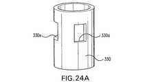
縫合装置300の足部用の代替的構成に加え、縫合装置300は、連結部312との細長いボディ306および306’の係合を可能にする代替的カフ構成も含み得る。そのような代替的構成の一例を、図24Aに関して示している。図24Aは、ペネトレータ先端330の代替的実施形態の斜視図を示す。この実施形態では、図24Bに関して示すように、ペネトレータ先端330は、ペネトレータ先端330がカフ310と係合するときに、先に記載したカフ310のカフタブ310aと係合するかみ合い面330aを含む。このようにして、ペネトレータ先端308およびカフ310に関して説明したように、使用者は、ペネトレータ先端窓330aをカフタブ310と係合した後、プッシュマンドレル315を用いてペネトレータ先端330から細長いボディ306を分離する。かみ合い面330aは、ペネトレータ先端330内に形成された窓などの切欠き部であってよい。細長いボディ306および306’は、また連結部312と係合し得る。 In addition to an alternative configuration for the foot of the
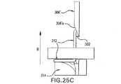
図25Aは、細長いボディ306および306’を連結部312と結合させる代替的方法を示している。この実施形態では、細長いボディ306’は、細長いボディ306’が足部314に入るときに、連結部312と係合するループ332(図25Bに示す)を含む。この実施形態では、連結部312は、ポリプロピレンまたはばね様特性を有する他の任意の材料など、連結部312と接触するループ332に応答して屈曲する弾性材料から作成されている。細長いボディ306’は、ループ332が連結部312の端部312aと接触するまで、方向矢印Aで示した下方向に動く。ループ332が端部312aと接すると、ループ332は、端部312aを方向矢印F1で示した方向F1に動かす。図25Bに関して示したように、止め部332は、ループ332が端部312aと接するまで、連結部312の端部312aを方向F1に移動し続ける。 FIG. 25A illustrates an alternative method of coupling
図25A〜図25Cを参照すると、連結部312は、ばね様特性を有する材料から構成されている。したがって、ループ332aが端部312aと接触するとき、連結部312の弾性特性が、端部312aを、図25Aの方向矢印F2によって示すような方向F2に動かす。図25Bに関して示したように、端部312aは、端部312aがループ332a内に入るように方向F2に移動する。一旦、端部312aがループ332a内に入ると、使用者は、端部312aおよび連結部312と共にループ332aを、図25Cの方向矢印Bによって示したような方向Bに引っ込める。ループ332aおよび止め部332は方向Bに移動するので、ループ332aは、細長いボディ306’の表面306a’に対して連結部312を締め付ける。したがって、縫合装置300が足部314から引っ込む間、図25Cに関して示したように、連結部312は、細長いボディ306’と係合したままになる。また図25Cに関して示したように、細長いボディ306’および止め部332が足部314から引っ込むので、止め部332は、足部314を通して連結部312を引っ張る。止め部332が連結部312を引っ張る間、切開部の縫合を可能にするために、カフ310(図示せず)および縫合糸302(図示せず)は、足部314を通る。 Referring to FIGS. 25A to 25C, the connecting
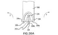
別の実施形態では、図26Aに関して示すように、縫合装置300は、細長いボディ306および306’を連結部312と結合させる、クリップおよびリングアセンブリ338を使用することもできる。図26Aは、本発明のある実施形態による、細長いボディ306および306’を連結部312と結合させる、クリップおよびリングアセンブリ338の略図を示している。細長いボディ306および306’は、ペネトレータ先端308および針先308’の代わりにクリップ336を含み、クリップ336は、図26Aに関して示したような構成を有する。クリップ336は、可撓性のアーム336aおよび通路336bを含む。 In another embodiment, as shown with respect to FIG. 26A, the
クリップおよびリングアセンブリ338は、クリップ336と係合するリング334も含む。連結部312は、結束等の任意の適した技術を用いてリング334と結合する。細長いボディ306および306’が足部314と係合するときに、クリップ336がリング334と結合するように、リング334は、図26Bに関して示したような円形構成を有する。クリップ336がリング334と係合すると、可撓性アーム336aは、方向矢印YおよびZで示した方向に屈曲し、これにより図28Cに関して示したように、リング334がクリップ336を通ることができるように、通路336bの幅Wiが増大される。 Clip and
図26Dを参照すると、足部314が、カフポケット314b−1および314b−2を含んだ足部314の平面図が示されている。カフポケット314b−1は、クリップ336と係合する前に、リング334を保持する。カフポケット314b−2は、細長いボディ306および306’が足部314に入るときに、図26Dに関して示したように、クリップ336が、カフポケット314b−2に入り、かつリング334と係合するように構成されている。一旦、クリップ336がリング334と係合すると、細長いボディ306と結合されたクリップ336は、クリップ336から分離され、細長いボディ306’は、クリップ336と係合したままになる。細長いボディ306および306’が足部314から引っ込む間、切開部を縫合するために、細長いボディ306’は、足部314を通して連結部312および縫合糸302を引っ張る。 Referring to FIG. 26D, a plan view of the
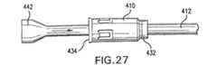
図27は、本発明の種々の実施形態に提供され得る、カフ410および連結部412アセンブリのある実施形態を示している。カフ411は、ペネトレータ先端受取り端部434およびテーパ端部432を有する。連結部412は、2つの端部442を有する(図27には1つのみを示す)。好適な連結部材料の一例は、延伸ポリテトラフルオロエチレン(ePTFE)である。PTFEは、一般にはTeflon(登録商標)と呼ばれる。ePTFEは、低摩擦で高強度の特性があるので、本願明細書に記載の管閉鎖装置において連結部材料として使用するのに特に適している。 FIG. 27 illustrates one embodiment of a
連結部およびカフアセンブリを組み立てるには、ある長さの連結部材料が、まずカフに通される。次に、カフ410のペネトレータ先端受取り端部434から延びる連結部材料の端部が、拡張するように加熱される。次に、拡張した端部部分442が、カフ410の内部のテーパ端部432内で固定されるように、連結部が、カフ410を通して引っ張られる。 To assemble the connection and cuff assembly, a length of connection material is first passed through the cuff. Next, the end of the coupling material extending from the penetrator
縫合装置の種々の実施形態は、編組されたまたは単繊維などの種々のタイプの縫合糸のいずれをも含み得る。縫合糸材料は、吸収性または非吸収性であってよく、ポリエステル、ポリプロピレン、ポリグリコール酸、ナイロン、絹、または当該分野で知られた種々の縫合糸材料の任意のものから作成されてよい。抗生物質または抗菌物質でコーティングされた縫合糸材料も、本発明の縫合装置に提供されてよい。 Various embodiments of the suturing device may include any of various types of sutures, such as braided or monofilament. The suture material may be absorbable or non-absorbable and may be made from polyester, polypropylene, polyglycolic acid, nylon, silk, or any of a variety of suture materials known in the art. An antibiotic or antimicrobial coated suture material may also be provided in the suturing device of the present invention.
例示的な縫合糸材料は、PTFEを含浸させた、マサチューセッツ州ケンブリッジのGenzyme Biosurgery社製造の編組されたポリエステル縫合糸材料であるTEVDEK II(登録商標)である。例示的な単繊維縫合糸材料は、同様にGenzyme Biosurgery社製造のポリプロピレン縫合糸材料であるDEKLENE II(登録商標)である。別の例示的な単繊維縫合糸材料は、同様にGenzyme Biosurgery社製造のナイロン単繊維である。編組されたポリエステルおよび単繊維ポリプロピレンまたはナイロンは、本発明の装置と共に使用することができる適した縫合糸材料であるが、図11A−1〜図11Eおよび図14A〜図21に関して記載した実施形態の予め結んだ結び目を形成するために、単繊維縫合糸材料は、製造後の処理が必要になる場合もある。 An exemplary suture material is TEVDEK II®, a braided polyester suture material manufactured by Genzyme Biosurgery of Cambridge, Mass., Impregnated with PTFE. An exemplary monofilament suture material is DEKLENE II®, a polypropylene suture material also manufactured by Genzyme Biosurgery. Another exemplary single fiber suture material is a nylon single fiber, also manufactured by Genzyme Biosurgery. Braided polyester and monofilament polypropylene or nylon are suitable suture materials that can be used with the device of the present invention, but in the embodiments described with respect to FIGS. 11A-1 to 11E and 14A to 21. Single fiber suture materials may require post-manufacture processing to form pre-knotted knots.
単繊維縫合糸材料は、編組された縫合糸材料に比べてより固くなり易い。このように、予め結んだ結び目を提供するために縫合糸のバイト部を形成することは、より可撓性のある編組された縫合糸を用いた場合よりも、単繊維縫合糸を用いた場合は困難である。単繊維縫合糸材料は、バイト部80(図11A−2および図11A−3に示した)を形成するためにループにされた後に、真っ直ぐになり易い。したがって、図11A−2および図11A−3、図15A(予め結んだ結び目104)、および図21(予め結んだ結び目304)に示したような、解けずに装置のシャフトに解放可能に配設される単繊維縫合糸のバイト部を提供するために、バイト部を形成するループが、バイト部を固めるために加熱される。バイト部を固めるために単繊維縫合糸のバイト部を加熱することは、延伸、アニーリング、または熱を用いて縫合糸材料を製造する他の処理を含み得る、任意の製造処理を縫合糸が受けた後に実行される。 Single fiber suture materials tend to be stiffer than braided suture materials. In this way, forming a suture bite to provide a pre-knotted knot is more difficult with a single fiber suture than with a more flexible braided suture. It is difficult. The monofilament suture material tends to straighten after being looped to form the bite 80 (shown in FIGS. 11A-2 and 11A-3). Therefore, as shown in FIGS. 11A-2 and 11A-3, FIG. 15A (pre-knotted knot 104), and FIG. In order to provide a single fiber suture bite, the loop forming the bite is heated to solidify the bite. Heating the single fiber suture bite to consolidate the bite may include any manufacturing process, including drawing, annealing, or other processes that use heat to produce the suture material. Will be executed after.
本発明の縫合装置用の予め結んだ結び目を形成する方法は、第1の端部を有するある長さの単繊維縫合糸を提供する工程、ある長さの単繊維縫合糸の一部分をマンドレルの周囲に巻いて、第1の端部から離間されたループ状構成にする工程、およびマンドレルを除去した後に、巻かれた部分がループ状構成のままであるように、単繊維縫合糸の融点未満まで巻かれた部分を加熱する工程を含む。 A method of forming a pre-knotted knot for a suturing device of the present invention includes providing a length of a single fiber suture having a first end, a portion of a length of a single fiber suture being placed on a mandrel. Less than the melting point of the monofilament suture so that the wound portion remains looped after the mandrel is removed and the looped configuration spaced around the first end and wound around A step of heating the portion wound up to.
縫合糸のバイト部は、少なくとも1つのループを含む。少なくとも1つのループの加熱は、バイト部をループ構成で固めるように実行される。この温度は、縫合糸材料の融点未満に保たれるが、バイト部が加熱から除去された後に、縫合糸が形成されたループ状構成のままであるように選択される。温度は、縫合糸の強度などの特性に悪影響を与えないように選択される。 The suture bite includes at least one loop. Heating of at least one loop is performed to consolidate the bite portion in a loop configuration. This temperature is selected to be kept below the melting point of the suture material, but remain in the looped configuration with the suture formed after the bite is removed from the heating. The temperature is selected so as not to adversely affect properties such as suture strength.
ある例示的な加熱工程では、ある長さのサイズ3/0ポリプロピレン縫合糸が、マンドレルの周囲でループ状にされて、約115.6℃(華氏240度)〜約126.7℃(華氏260度)、または名目的には約121.1℃(華氏250度)の温度で約3秒間〜約5秒間、加熱されるバイト部が形成される。加熱は、約10〜約30標準立方フィート/時(scfh)、または名目的には約20scfhの速度の風量を提供する、ヒートガンなどのブロー式熱源によって行われる。形成されたバイト部の加熱は、約93.3℃(華氏200度)〜約137.8℃(華氏280度)に加熱されたオーブンで行われてもよい。オーブンを用いてバイト部が形成されるとき、バイト部が、オーブンの加熱内で保持される時間量は、約1分〜約15分である。具体的な加熱温度および時間は、異なる縫合糸のサイズまたはタイプ、あるいはタイプの異なるバイト部構成に関して適切であるように選択され得る。 In one exemplary heating step, a length of size 3/0 polypropylene suture is looped around the mandrel to provide a temperature of about 115.6 ° C. (240 ° F.) to about 126.7 ° C. (260 ° F.). Degree), or nominally, a bite that is heated at a temperature of about 121.1 ° C. (250 ° F.) for about 3 seconds to about 5 seconds. Heating is performed by a blown heat source, such as a heat gun, that provides a flow rate of about 10 to about 30 standard cubic feet per hour (scfh), or nominally about 20 scfh. The formed bite portion may be heated in an oven heated to about 93.3 ° C. (200 ° F.) to about 137.8 ° C. (280 ° F.). When the bite portion is formed using an oven, the amount of time that the bite portion is held within the oven heat is from about 1 minute to about 15 minutes. The specific heating temperature and time may be selected as appropriate for different suture sizes or types, or different types of bite configurations.
別の実施形態では、単繊維ナイロン縫合糸材料を提供して、本発明の縫合装置において予め結んだ結び目を形成することもできる。サイズ3/0ナイロン縫合糸で形成されたバイト部が、バイト部を固めるために加熱される温度は、ヒートガンなどのブロー式熱源を用いて、約87.8℃(華氏190度)〜約98.9℃(華氏210度)、および名目的には約93.3℃(華氏200度)で、約3分〜約5分である。オーブンを用いる場合、バイト部を固めるのに使用される温度は、約87.8℃(華氏190度)〜約98.9℃(華氏210度)、または名目的には約93.3℃(華氏200度)で、約1分から約15分である。 In another embodiment, a single fiber nylon suture material can be provided to form a pre-knotted knot in the suturing device of the present invention. The temperature at which the bite portion formed of size 3/0 nylon suture is heated to harden the bite portion is about 87.8 ° C. (190 ° F.) to about 98 using a blow type heat source such as a heat gun. .About.9.degree. C. (210.degree. F.), and nominally about 93.3.degree. C. (200.degree. F.) for about 3 minutes to about 5 minutes. When using an oven, the temperature used to harden the bite is about 87.8 ° C. (190 ° F.) to about 98.9 ° C. (210 ° F.), or about 93.3 ° C. for nominal purposes ( It is about 1 minute to about 15 minutes at 200 degrees Fahrenheit.
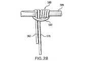
図28は、バイト部を固めるためにバイト部のループを加熱する準備中の、マンドレル589周囲に巻かれた単繊維縫合糸のバイト部580を示している。マンドレルは、例えば、約0.65mmの径を有するポリイミドのシャフトまたはチューブであってよい。図28に示した例では、縫合糸は、サイズ3/0であり、巻き付けられて、クリンチ式の結び目を定めるループ状構成を形成している。図28に示したように縫合糸を巻き付けるために、ある長さの縫合糸が、第1の端部576がマンドレルと交差して向けられて、マンドレルに対して保持される。ある長さの縫合糸の第2の端部は、マンドレルに5回巻き付けられる。次に、この第2の端部が、第1の端部の上に巻き付けられて、第1の5つのループに対して横断方向のループ590を形成する。次に、第2の端部が、マンドレルの後ろでループにされ、第1の5つのループから反対方向にマンドレル上に巻き付けられる。次に、第2の端部は、ループ590を通されて、予め構成または予め結ばれた結び目を形成する。 FIG. 28 shows a single
図29は、シャフト12の周囲に配設された縫合糸の予め結んだ結び目100をさらに含む、本発明の別の実施形態を示している。針38は、各々、針の端部に取り付けられた着脱可能な針先78を有する。着脱可能な針先78には、各々、縫合糸34の両端が取り付けられる。図11A−1〜図11Eに関して先に記載したように、バイト部80は、縫合糸34の一端がそのバイト部を通るときに、予め結ばれた結び目100を定めるように予め構成されている。結び目の一例を、上の図11A−3に関して記載した。バイト部80は、2つ以上のループを含むことが多く、種々の知られているか、または新規の結び目を定めるように、予め構成されてよいことに留意されたい。 FIG. 29 illustrates another embodiment of the present invention that further includes a
操作中、足部24が(図示のように)展開された後、針38の各々は、縫合糸34の反対側の端部を足部24に向けて運ぶ。針38が、組織を通して進められ足部24のレセプタクル52に入るときに、縫合糸34の両端が、着脱可能な針先端78と共にレセプタクル52内に付着されるように、各針38は、着脱可能な先端78を含む。次に、着脱可能な針先端78は、例えば、中空針の内側からプッシュマンドレル(図示せず)によって針38から分離される。別の場合には、先端78は、針が足部から引っ込められると、針38から引っ張られるように、摩擦的または機械的にレセプタクル52内に保持されてよい。次に、先端78のない針38は、シャフト12内に引っ込められ、次に縫合糸34両端と共に先端78を運ぶ足部24は、展開されていない位置内に回転されて戻される。 In operation, after the
シャフト12が患者の身体から除去されるとき、足部24は、その非展開位置にあり、縫合糸34の両端は、シャフト12の中央軸近傍にある。次に、予め結んだ結び目100は、シャフト12を縫合糸34の両端を超えて滑降されて、その結果、縫合糸34の両端が、バイト部80を通って上方に向かい予め結んだ結び目100を形成する、図30に示したような縫合糸パターンが得られる。 When the
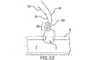
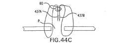
図31は、以下に示すように、シャフト12周囲に配設された縫合糸の予め結んだ結び目100も含む、本発明の別の実施形態を示している。針38Aは、縫合糸34の一端を運ぶ。着脱可能な先端78が、針38Aの端部に配設されている。着脱可能な先端78は、(図11A−1に示した縫合糸34の端部76に類似する)縫合糸端部76に接続されている。上記のように、さらに、接続繊維74が足部24に設けられている。 FIG. 31 illustrates another embodiment of the present invention that also includes a
操作中、針38Aは、(図示のように)足部24が展開された後、縫合糸34の一端76を足部24に向かって運ぶ。針38Aは、針38Aおよび38Bが、足部24のレセプタクル52内に進められるときに、縫合糸34の端部が、接続繊維74の一端に接続されるように、着脱可能な先端部78を含む。針38Bは、接続繊維74の他端に接続される。次に、針38Aおよび38Bは、シャフト12内に引っ込められ、次いで、足部24は、非展開位置に回転して戻される。針38Aが引っ込められたとき、先端部78および縫合糸端部76が、針38Aのシャンクから分離される。針38Bは、接続繊維74と係合され、次に着脱可能な先端部78と係合される。縫合糸端部76は、先端部78に取り付けられる。したがって、針38Bが引っ込められたとき、バイト部80を通して接続繊維74および縫合糸端部76を引っ張ることによって、針38Bは、バイト部80の中央を通ってシャフト12に入って、予め結んだ結び目100を形成する。 In operation, the
シャフト12が患者の身体から除去されるとき、予め結んだ結び目100は、シャフト12を滑り降り、その結果、縫合糸34の端部76がバイト部80を通って上方に移動する、図32に示したような縫合糸パターンが得られる。 When the
図32の予め結んだ結び目によって形成される縫合糸パターンは、図30の縫合糸パターンとは異なる。具体的には、図30では、縫合糸34の両端は、共に穿刺部Pを通って外方向に行くが、図32に示した縫合糸パターンでは、縫合糸34の両端は、穿刺部Pを通らないが、穿刺部に隣接する管壁を通る。 The suture pattern formed by the pre-knotted knot of FIG. 32 is different from the suture pattern of FIG. Specifically, in FIG. 30, both ends of the
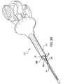
図33は、以下のように、シャフト12周囲に配設された予め結んだ結び目100も含む、本発明のさらに別の実施形態を示している。縫合糸34の両端の各々は、レセプタクル52内に位置決めされている。足部24が(図示のように)配置された後、針38は、下方に進められるので、針38の各々が、レセプタクル52の場所において縫合糸34の反対の端部に接続される。わかり易いように、接続部の具体的な詳細は、図33には示していない。しかし、針38を縫合糸34の端部に接続するのに適したシステムの一例は、図4で上述されている。 FIG. 33 illustrates yet another embodiment of the present invention that also includes a
針38が縫合糸34の両端に接続された後、針38は、共にシャフト12の管腔内に引っ込められ、これにより、縫合糸34の両端がシャフト12を通って、かつ縫合糸のバイト部80を通って引っ張り上げられて、(図示のように、シャフト12の外面周囲に最初に配設された)予め結んだ結び目100を定める。 After the
シャフト12が患者の身体から除去されると、予め結んだ結び目100は、シャフト12を滑り降り、その結果、縫合糸34の両端が図示のような結び目100の中央を通って上方に向かう、図34に示したような縫合糸パターンが得られる。 When the
図34の縫合糸パターンは、図30の縫合糸パターンと僅かに異なるが、図30および図34は、共にバイト部80の中央を通って結び目100を形成する縫合糸34の両端を示している。具体的には、図30の縫合糸パターンを形成するとき、縫合糸34の両端は、共に組織壁Wを通って下方に向かい、穿刺部Pを通って上方に向かう。一方で、図34の縫合糸パターンを形成するとき、縫合糸34の両端は、共に穿刺部Pを通って下方に向かい、組織壁Wを通って上方に向かい、さらにバイト部80を通って結び目100を形成した。 The suture pattern of FIG. 34 is slightly different from the suture pattern of FIG. 30, but FIGS. 30 and 34 both show the ends of the
図35は、米国特許第6245079号に示した実施形態に類似するが、本発明の予め結んだ結び目も含んでいる縫合装置220の図である。本明細書には、米国特許第6245079号の全体が参照によって組み込まれる。 FIG. 35 is a view of a
図35に見られるように、針246を中に備えた中空体214を有する縫合糸導入器頭部222が設けられている。延ばされた位置にあるとき、可撓性針246は、装置の軸から外方向に屈曲する。 As seen in FIG. 35, a
中空体214は、その中に縫合糸鉤腕224の近位で、(針246につき1つの)2つの針口または開口部210が形成されている。装置の場合、各縫合糸鉤腕224は、中空体214内のアクチュエータロッド(図示せず)に力を加えることによって、引っ込められた位置まで移動される。縫合糸鉤腕224は、針保持部分225内で縫合糸34のループ状の両端を保持する。 The
針246は、針開口部210を通って縫合装置220から滑り出る。針246は、径方向に外側に屈曲して、穿刺部のいずれかの側の管壁(図示せず)を貫通する。
針246上の縫合糸止め部238は、縫合糸鉤腕224によって保持された縫合糸ループ35を引っ掛け、針246が近位に引っ込められるときに、穿刺された穴を通して縫合糸34の両端を引っ張り上げる。針246が、針管腔(図示せず)内に引っ込められるとき、針246は、真っ直ぐな形状に戻る。 A
本発明によれば、図示のように、縫合糸バイト部80は、バイト部80の中央部分が、装置220の外側に巻き付けられた予め結んだ結び目100を備えた、ハウジングの外面に配設されている。この実施形態では、縫合糸34は、図35に示した装置の内側を通らない。しかし、本発明の他の実施形態は、装置のシャフトまたはハウジングの外側ではなく内部に格納された縫合糸34および湾曲80を含み得ることを理解されたい。さらに他の構成は、先に示した実施形態に関して上述した着脱可能な先端部またはリンク特徴を含み得る。 In accordance with the present invention, as shown, the
針246が、縫合糸34の両端を回収し、バイト部80の中央を通して縫合糸のこれらの両端を引っ張り上げ戻されて、予め結んだ結び目100を定め、縫合糸鉤腕224が、展開されていない位置まで回転されて戻された後、装置220は、患者から除去され得る。予め結んだ結び目100は、シャフトを滑降し、その結果、縫合糸34の両端がバイト部80の中央を通って上方に向かう、図34に示した縫合糸パターンと同じ縫合糸パターンが得られる。 A
図36〜図38は、本発明の予め結んだ結び目を組み入れた、米国特許第5613974号に示されたような装置の図である。本明細書には、米国特許第5613974号の全体が参照によって組み込まれている。 FIGS. 36-38 are views of an apparatus such as that shown in US Pat. No. 5,613,974, incorporating the pre-tied knot of the present invention. No. 5,613,974 is hereby incorporated by reference in its entirety.
図36は、縫合装置310を示し、この縫合装置310は、案内体312、案内体312の遠位端に固定された針案内部314、および針案内部314の遠位端に固定された可撓性針シース316を備える。組織受取り領域346が、針案内部314および案内体312の遠位面によって定められている。針320が、ホルスター内のその遠位端が往復運動可能なシャフト(図示せず)に取り付けられた状態で搭載されている。シース316から針案内部314を通して案内体312内まで針320を引くために、ハンドル328が、近位に引っ張られ得る。さらに、縫合装置310は、予め結んだ縫合糸の結び目100を送る能力を備えている。 FIG. 36 shows a
案内体312、針案内部314、可撓性針シース316、針320、組織受取り領域346、およびハンドル328は、全体的に、米国特許第5613974号の案内体12、針案内部14、可撓性針シース16、針20、組織受取り領域346、およびハンドル28に相当する。
図36を参照すると、縫合糸34の両端は、各々針320の端部に接続されている。バイト部80は、案内体312の周囲に配設され、縫合糸34の両端が該バイト部を通過するときに、予め結んだ結び目100を定めるように予め構成されている。バイト部80は、1つまたは複数の縫合糸34のループを含んでよく、種々の知られた結び目または新規な結び目を定めるように予め構成され得る。 Referring to FIG. 36, both ends of the
縫合糸34の位置決めのさらなる詳細を、図37に示している。針320が、組織Tの層を通して近位に展開され、かつ案内体312の管腔内に受け取られた後、バイト部80は、装置のシャフトを滑降し、図30に示した縫合パターンと類似するか、または同じ縫合糸パターンを形成し、この場合縫合糸34の両端は、バイト部80の1つまたは複数のループを通されて、予め結んだ結び目を形成する。 Further details of the positioning of the
図38は、構成が変更されたバイト部80を含む縫合装置310を示している。バイト部80は、組織受取り領域346内に予め配置された第1の部分80A、および案内体312上に予め配置された第2の部分80Bを含む。第1の部分80Aおよび80Bを含んだバイト部80は、縫合糸34の両端がバイト部を通るときに、予め結んだ結び目100を定めるように予め配置されている。バイト部80は、縫合糸34の1つまたは複数のループを含んでよく、種々の知られた結び目または新規な結び目を定めるように予め配置され得る。 FIG. 38 shows a
図39は、装置でのバイト部80の配置を示している。組織受取り領域346および案内体312に、変更された「8の字」形状にバイト部80を巻き付けるために、第1の部分80Aおよび第2の部分80Bを形成するループが巻き付けられる間に、仮止めピン313を設けて、バイト部80を形成するループの中間部分を適所に保持する。一旦、バイト部80が、デバイスで適所に収まると、ピン313が除去され、バイト部80が、接着剤、または収縮包装チューブ(図示せず)などの被覆物を用いて装置本体上に保持される。装置の展開中、針320は、ある長さの縫合糸34のそれぞれ第1および第2の端部を、バイト部80の第1の部分80Aを超えて案内体312の中に運ぶ。 FIG. 39 shows the arrangement of the
図40は、縫合糸34および針320アセンブリの略図を示しており、バイト部80は、バイト部80を形成する縫合糸ループの経路を見易いように平らに配置されている。組織受取り領域346の断面図を囲んでいる第1の部分80Aが示されている。案内体312の断面図を囲んでいる第2の部分80Bが示されている。針受取り管腔372が、案内体312を通って定められている。バイト部80が、装置の本体に予め配置されるときに、バイト部80が、図40の線AおよびBに沿って折り畳まれるように見えることができる。 FIG. 40 shows a schematic representation of the
図41は、血管壁などの組織の壁W内に展開された予め結んだ結び目100を示している。予め結んだ結び目100は、図23、図24A、および図24Bに示した装置および縫合糸バイト部80の構成が展開された結果である。 FIG. 41 shows a
図42〜図46は、米国特許第6436109号または米国特許第6451031号に示した縫合装置が、予め結んだ結び目を組み入れた、本発明の別の実施形態を示している。具体的には、図42〜図44は、そのような装置の一実施形態を示し、図45および図46は、そのような装置の別の実施形態を示している。米国特許第6436109号および米国特許第6451031号は、その全体を本明細書に参照によって組み込まれる。 FIGS. 42-46 show another embodiment of the present invention in which the suturing device shown in US Pat. No. 6,436,109 or US Pat. No. 6,510,013 incorporates a pre-tied knot. Specifically, FIGS. 42-44 show one embodiment of such a device, and FIGS. 45 and 46 show another embodiment of such a device. US Pat. No. 6,436,109 and US Pat. No. 6,510,013 are hereby incorporated by reference in their entirety.
図42および図45は、断面が円形または実質的に円形のチューブ416を含む縫合装置401を示している。チューブ416は、近位部分418および遠位部分424を有する。近位部分418は、第1の端部420から接続部分422まで延びる。近位部分418は、その間を通って第1の針開口部410まで延びる第1の針管腔(図示せず)を有する。遠位部分424は、接続部分422から遠位方向に延びる。図43を参照すると、遠位部分424は、接続部分422によって定められた組織受取り空隙426を横切って、第1の針開口部410と向き合う第2の針開口部433を含む。第2の針開口部433は、第2の針管腔(図示せず)内へと開口している。 42 and 45 show a
図42および図45を再び参照すると、接続部分422は、弓形を有しており、近位部分418と遠位部分424との間に結合されている。接続部分422は、組織受取り空隙426を形成するように、近位部分および遠位部分からずらされている。この接続部分が、解剖学的構造体の穿刺部内に受け取られるとき、組織受取り空隙内に受け取られた解剖学的構造体の一部分は、穿刺部の中心シャフトを含む平面の一方の側に位置決めされる。 Referring again to FIGS. 42 and 45, the connecting
図42および図43を参照すると、縫合糸34は、第2の針開口部433の周囲に配設された縫合糸のバイト部80を含む(図43)。本発明のこの態様では、各針のは、縫合糸34の両端に接続される。操作中、針437Aおよび437B(図42)は、第1の針開口部410から出て空隙426をわたり、第2の針開口部433内まで連続的に進められる。 42 and 43, the
バイト部80は、縫合糸34の少なくとも1つの端部がバイト部を通過するとき、予め結んだ結び目100(図43)を定めるように予め配置されている。バイト部80は、2つ以上のループを含んでよく、種々の知られた結び目または新規な結び目を定めるように予め配置され得る。 The
図44A〜図44Dは、閉鎖される穿刺部Pを有する組織壁Wに対する、バイト部80を通る針437Aおよび437Bならびに縫合糸の展開のシーケンスを示す略図である。このシーケンスは、図42および図43に示した予め結んだ結び目の実施形態の操作を示す。 44A-44D are schematic diagrams showing the sequence of deployment of
図44Aは、組織壁Wの下に位置決めされたバイト部80を示している。針437Aは、穿刺部Pに隣接する組織壁Wを通して進められ、バイト部80を通して縫合糸34の一端部を運ぶ。 FIG. 44A shows the
図44Bは、穿刺部Pの反対側に位置決めされたバイト部80を示している。第2の針437Bは、穿刺部Pに隣接する組織壁Wを通して進められ、バイト部80を通して縫合糸34の一端部を運ぶ。この段階では、針437Aおよび437Bは共に、装置の遠位部分(説明を簡単にするために図示せず)に配設される。 FIG. 44B shows the
図44Cは、装置(図示せず)が穿刺部Pを通して近位方向に引っ込められた後の、バイト部80および針437Aおよび437Bの位置を示している。図44Dは、穿刺部P近傍まで進められ、そこに確実に締め付けられた後の、予め結んだ結び目100の最終位置を示している。 FIG. 44C shows the position of the
図45および図46を参照すると、バイト部80は、接続部分422周囲に配設されている。本発明のこの態様では、各針437Aおよび437Bは、縫合糸34の両端に接続されている。操作中、針437Aおよび437Bは、第1の針開口部410を出て、接続部分422を横切って第2の針開口部433内まで連続的に進められている。針437Aおよび437Bは、近位部分418から遠位部分424まで遠位方向に進みながら、組織受取り空隙426を横断するときに、バイト部80(図46)を超えて通過する。 Referring to FIGS. 45 and 46, the cutting
装置401が患者身体から除去された後、縫合糸34の両端が、バイト部80を通されて予め結んだ結び目100を形成するように、バイト部80は、接続部分422および遠位端部424を超えて滑降する。 After the
先に記載した縫合装置の実施形態の多くでは、針を用いて、縫合糸のループが組織壁の開口部を横切って位置決めされる。針は、縫合糸に取り付けられ、針によって形成された組織の貫通部を通して縫合糸を引っ張る。組織を通して針を進めて、縫合糸(または接続繊維)に取り付けることもでき、または進められて組織を貫通する前に、縫合糸に取り付けることもできる。いずれの場合も、針が引っ込められた後、針を分離するために、縫合糸は切断されなければならない。縫合糸がハウジングを通して引っ込められる本明細書に記載のいくつかの実施形態では、装置が、患者の解剖学的構造から除去されるように、1つまたは複数の針は、縫合糸から分離されなければならない。多くの場合、縫合糸は、鋏またはメスを用いて切断または切り離される。縫合装置の付加的な実施形態は、好都合な切断縁を提供して、縫合糸を切断して、1つまたは複数の針から縫合糸を分離するために、装置に位置決めされた刃を含み得る。 In many of the suturing device embodiments described above, a needle is used to position the suture loop across the tissue wall opening. The needle is attached to the suture and pulls the suture through the tissue penetration formed by the needle. The needle can be advanced through the tissue and attached to the suture (or connecting fiber), or it can be attached to the suture before it is advanced and penetrates the tissue. In either case, after the needle is retracted, the suture must be cut to separate the needle. In some embodiments described herein where the suture is retracted through the housing, the one or more needles must be separated from the suture so that the device is removed from the patient's anatomy. I must. In many cases, the suture is cut or cut using a scissors or scalpel. Additional embodiments of the suturing device may include a blade positioned on the device to provide a convenient cutting edge to cut the suture and separate the suture from one or more needles. .
図47は、本明細書に記載の連接可能な足部を有するタイプの縫合装置610を示している。縫合装置610は、経皮経管的カテーテル処置等の終了後に、患者の大腿動脈の開口部を縫合するのに特に有用である。縫合装置610は、装置に位置決めされた刃を含み得る装置のタイプの一例である。わかり易いように、この縫合装置の実施形態のみを、縫合糸切断刃特徴に関して記載する。しかし、針および縫合糸を用いて組織壁の開口部を閉鎖する任意の縫合装置が、以下により完全に記載する縫合糸切断刃特徴を組み入れてよいことを理解されたい。 FIG. 47 illustrates a
図47に示した縫合装置610は、ハウジング618を含む。1つまたは複数の針638が、作用的に装置に結合されている。針638は、ハウジング618に対して可動である。図47には、ハウジング618から引っ込められた針638を示している。この例示的実施形態では、ある長さの縫合糸634に取り付けられた、2本の針638の一方のみを示している。他の実施形態では、両方の針が、縫合糸634に取り付けられ得る。別の場合には、この装置が含む針は1本のみでもよい。 47 includes a
針638および取り付けられた縫合糸634が、装置から引っ込められるときに、縫合糸634が、刃690を横切って引き出されて縫合糸が切断されるように、縫合糸切断刃690が、装置610に位置決めされている。図47は、縫合糸が切断されてある長さの縫合糸から針638が分離される直前の、ハウジング618および刃690に対する針および縫合糸の位置を示している。図47に見られるように、縫合糸が針の端部から短い距離で切断されているために、縫合糸の一部は、針638に取り付けられたままであり得る。組織の開口部を閉鎖するのに用いられるある長さの縫合糸は、1つまたは複数の針から分離される。ハウジング618の近位端622から既に引っ込められたある長さの縫合糸から、針638が切断されると、針作動ハンドル620から干渉されることなく、装置610を患者の解剖学的構造から除去することができる。 A
図48は、ハウジングに刃690が設けられたハウジング618の断面図を示している。略V字型の切断縁を有する刃690が示されている。刃の別の実施形態は、直線、曲線、鋸歯、または任意の種々の切断縁形状または構成を有してよい。刃は、ハウジングに取り付けられる別個の部品であってよい。例えば、ステンレス鋼または他の金属から作製された刃は、プラスチック製ハウジングに取り付けられるか、または設置され得る。オーバーモールディングなどの他のよく知られた技術を用いて、刃およびハウジングが組み立てまたは形成されてよい。別の場合には、例えば、ハウジング上の選択された場所に鋭い縁を成形または機械加工することによって、刃は、プラスチック製ハウジング内に一体形成されてよい。刃は、刃が位置決めされる、ハウジング、または装置の他の構成要素に対して固定して設けられてよい。別の場合には、移動する切断縁を提供するように、刃は、可動的に設置されてよい。 FIG. 48 shows a cross-sectional view of a
図48に示すように、ハウジング618は、遠位端624および近位端622を有する。刃690は、遠位端624近傍に位置決めされており、縫合糸は、近位端622からハウジング618を通って引っ込められる。次に、この縫合糸は、刃を横切って引き出されるように、刃に向かって遠位方向に向けられる。刃の切断縁は、ハウジングおよび装置の操作者に対して遠位方向を向く。この刃の位置およびこの切断縁の向きによって、操作者は、刃の切断縁を横切って縫合糸を通すか、または縫合糸をループにすることが可能になるとともに、近位方向に引っ張って、刃を横切って縫合糸を引き出して、縫合糸を切ることが可能となる。縫合糸がハウジングを出る位置に対する刃の位置によって、結果として、縫合糸は、縫合糸が切断された後に、十分な長さの縫合糸尾部が残されるその長さに沿った場所で切断されることになる。縫合糸尾部(または尾部の対)を用いて、結び目が締められ、結び目が縫合される組織まで進められる(または予め結んだ結び目が進められる)。 As shown in FIG. 48, the
ハウジング618は、刃の切断縁へのアクセスを提供する開口部625を定める。図47および図48に示した実施形態では、開口部625は、ハウジングの遠位端624近傍に定められ、刃690は、その開口部内に位置決めされている。刃保護具628を設けて、損傷から刃を保護すること、または刃によって生じる傷害から装置の使用者を保護することができる。 The
図49は、ハウジング618を含む縫合装置610の一部を示している。図49は、縫合糸切断刃のための別の場所を示している。ハウジング618は、近位端622および遠位端624を有する。ハウジングは、ハウジングに可動に設けられた足部ハンドル626も含む。ハウジング618は、ハウジングからハウジングの近位端622近傍に延びる指グリップ619も含む。 FIG. 49 shows a portion of the
図50は、図49のハウジング618の近位端622の拡大部分図である。この実施形態では、縫合糸切断刃691は、ハウジングの近位端近傍に位置決めされている。刃691は、ハウジングの外面に設けられている。 50 is an enlarged partial view of the
図51は、図49のハウジング618の近位端622の拡大端面図である。図51に示すように、ハウジング618は、近位開口部623および内面621を有する中空体である。この実施形態では、縫合糸がハウジングから引っ込められるときに、縫合糸が側方に動かされて、縫合糸切断刃691を横切って引き出されて切断されるように、縫合糸切断刃691は、近位開口部の内面621に設けられている。 51 is an enlarged end view of the
図52は、図49のハウジング618の指グリップ619の拡大した近位端面図である。縫合糸切断刃693が、指グリップ619に設けられている。この例示的実施形態では、縫合糸は、ハウジングの近位端から引っ込められ、指グリップ619の端部の上で刃619を横切ってループにされ、縫合糸を切断することができる。 52 is an enlarged proximal end view of
図53は、ハウジング618に対して可動に設けられた足部ハンドル626の拡大図である。足部ハンドル626を用いて、本明細書に記載の縫合装置の種々の実施形態において足部が展開される。縫合糸切断刃694が、可動ハンドル626に設けられている。 FIG. 53 is an enlarged view of a
操作中、組織縫合装置は、針を遠位方向に進めて組織を貫通し、該組織を通して縫合糸を位置決めすることによって用いられる。本明細書に記載の種々の実施形態では、針への縫合糸の取り付けは、装置のハウジングを通して遠位方向に針を動かして、縫合糸に接続することによって達成される。縫合糸は、ハウジングの近位端を通して近位方向に針を引っ込めることによって、組織を通して位置決めされる。最後に、縫合糸切断刃を横切って縫合糸を引いて縫合糸から針を切断することによって、縫合糸から針を分離することができる。 In operation, the tissue suturing device is used by advancing the needle distally through the tissue and positioning the suture through the tissue. In various embodiments described herein, attachment of the suture to the needle is accomplished by moving the needle distally through the device housing and connecting to the suture. The suture is positioned through the tissue by retracting the needle proximally through the proximal end of the housing. Finally, the needle can be separated from the suture by pulling the suture across the suture cutting blade to cut the needle from the suture.
本明細書に記載の縫合装置の種々の実施形態は、血管壁の開口部を横切って縫合糸を位置決めして開口部を閉鎖するために提供されることができる。大腿動脈閉鎖処置では、例えば、このような装置を用いて、皮下組織を通して経皮的に血管アクセス部位まで縫合糸および針が進められる。 Various embodiments of the suturing device described herein can be provided for positioning a suture across an opening in a vessel wall and closing the opening. In femoral artery closure procedures, for example, using such a device, sutures and needles are advanced percutaneously through the subcutaneous tissue to the vascular access site.
本発明は、組織壁に形成された切開部まで予め結んだ結び目を送る自動化された方法を外科医に提供する。本発明は、外科医が手作業で結び目を切開部位まで送ることに関する努力を簡素化する。したがって、本発明は、管腔に形成された切開部近傍に縫合糸の結び目を、的確かつ正確に位置決めするのに要する時間を短縮し、これによって、患者が処置および回復に費やす全体的時間、ならびにそれに付随する費用が低減される。 The present invention provides a surgeon with an automated method of sending a pre-knotted knot to an incision formed in a tissue wall. The present invention simplifies efforts related to manually sending a knot to the incision site by the surgeon. Thus, the present invention reduces the time required to accurately and accurately position the suture knot near the incision formed in the lumen, thereby reducing the overall time the patient spends on treatment and recovery, As well as the associated costs.
わかり易いように、例示的実施形態を若干詳細に説明したが、広範囲の多様な変更例、適用例、および変形は、当業者には明らかであろう。したがって、本発明の範囲は、特許請求の範囲によってのみ限定されるものである。 For clarity, the exemplary embodiment has been described in some detail, but a wide variety of modifications, applications, and variations will be apparent to those skilled in the art. Accordingly, the scope of the invention is limited only by the claims.
Claims (29)
Translated fromJapaneseハウジングと、
ある長さの縫合糸に取り付けられ、ハウジングに対して可動である針と、
縫合装置に位置決めされた縫合糸切断刃とを備え、針が縫合装置から引っ込められるときに、縫合糸が、縫合糸切断刃を横切って引かれることができる縫合装置。A suturing device,
A housing;
A needle attached to a length of suture and movable relative to the housing;
A suturing device comprising a suture cutting blade positioned on the suturing device, wherein the suture can be pulled across the suture cutting blade when the needle is retracted from the suturing device.
近位端および遠位端を有するハウジングと、
ハウジングに位置決めされた縫合糸切断刃と、
遠位端領域を有し、ハウジングの遠位端から延びる細長いシャフトと、
ハウジングの近位端を通って可動である針作動ハンドルと、
ハウジングを通り、かつさらにシャフトを通って針作動ハンドルから延びる針と、
装置によって運ばれる縫合糸とを備え、針が、縫合糸を近位方向に引っ張って組織を通って縫合糸を位置決めするように、縫合糸の一部が、シャフトの遠位端領域近傍に位置決めされる、縫合装置。A suturing device,
A housing having a proximal end and a distal end;
A suture cutting blade positioned in the housing;
An elongate shaft having a distal end region and extending from the distal end of the housing;
A needle actuation handle that is movable through the proximal end of the housing;
A needle extending from the needle actuation handle through the housing and further through the shaft;
A portion of the suture positioned near the distal end region of the shaft so that the needle pulls the suture proximally and positions the suture through the tissue. A suturing device.
遠位端および近位端を有するハウジングを含む装置を提供することを含み、ハウジングが、縫合糸を運び、装置がさらに、ハウジングに対して可動である針を含み、装置がさらに、ハウジングに位置決めされた縫合糸切断刃を含み、組織を縫合する方法がさらに、
組織を貫通させかつ組織を通して縫合糸を位置決めするために、針を遠位方向に進めることと、
針に縫合糸を取り付けることと、
ハウジングの近位端を通して近位方向に針を引っ込めることと、
縫合糸から針を分離するために、縫合糸切断刃を横切って縫合糸を引くこととを含む、方法。A method of suturing tissue,
Providing a device including a housing having a distal end and a proximal end, the housing further carrying a suture, the device further comprising a needle movable relative to the housing, and the device further positioned in the housing And a method for suturing the tissue, further comprising:
Advancing the needle in a distal direction to penetrate the tissue and position the suture through the tissue;
Attaching a suture to the needle,
Retracting the needle proximally through the proximal end of the housing;
Pulling the suture across the suture cutting blade to separate the needle from the suture.
Applications Claiming Priority (3)
| Application Number | Priority Date | Filing Date | Title |
|---|---|---|---|
| US10/660,288US8137364B2 (en) | 2003-09-11 | 2003-09-11 | Articulating suturing device and method |
| US10/660,288 | 2003-09-11 | ||
| PCT/US2004/029306WO2005025430A1 (en) | 2003-09-11 | 2004-09-09 | Articulating suturing device and method |
Publications (3)
| Publication Number | Publication Date |
|---|---|
| JP2007504902Atrue JP2007504902A (en) | 2007-03-08 |
| JP2007504902A5 JP2007504902A5 (en) | 2007-10-18 |
| JP4704341B2 JP4704341B2 (en) | 2011-06-15 |
Family
ID=34273632
Family Applications (1)
| Application Number | Title | Priority Date | Filing Date |
|---|---|---|---|
| JP2006526263AExpired - Fee RelatedJP4704341B2 (en) | 2003-09-11 | 2004-09-09 | Articulating suture device and method |
Country Status (7)
| Country | Link |
|---|---|
| US (5) | US8137364B2 (en) |
| EP (1) | EP1670361B1 (en) |
| JP (1) | JP4704341B2 (en) |
| AT (1) | ATE392856T1 (en) |
| AU (1) | AU2004272045B2 (en) |
| DE (1) | DE602004013351T2 (en) |
| WO (1) | WO2005025430A1 (en) |
Families Citing this family (177)
| Publication number | Priority date | Publication date | Assignee | Title |
|---|---|---|---|---|
| US20020095164A1 (en)* | 1997-06-26 | 2002-07-18 | Andreas Bernard H. | Device and method for suturing tissue |
| US7001400B1 (en) | 1999-03-04 | 2006-02-21 | Abbott Laboratories | Articulating suturing device and method |
| US20040092964A1 (en) | 1999-03-04 | 2004-05-13 | Modesitt D. Bruce | Articulating suturing device and method |
| US8137364B2 (en) | 2003-09-11 | 2012-03-20 | Abbott Laboratories | Articulating suturing device and method |
| US6964668B2 (en) | 1999-03-04 | 2005-11-15 | Abbott Laboratories | Articulating suturing device and method |
| US7842048B2 (en)* | 2006-08-18 | 2010-11-30 | Abbott Laboratories | Articulating suture device and method |
| US7235087B2 (en) | 1999-03-04 | 2007-06-26 | Abbott Park | Articulating suturing device and method |
| US7662161B2 (en) | 1999-09-13 | 2010-02-16 | Rex Medical, L.P | Vascular hole closure device |
| US6391048B1 (en) | 2000-01-05 | 2002-05-21 | Integrated Vascular Systems, Inc. | Integrated vascular device with puncture site closure component and sealant and methods of use |
| US9579091B2 (en) | 2000-01-05 | 2017-02-28 | Integrated Vascular Systems, Inc. | Closure system and methods of use |
| US6942674B2 (en)* | 2000-01-05 | 2005-09-13 | Integrated Vascular Systems, Inc. | Apparatus and methods for delivering a closure device |
| US7842068B2 (en) | 2000-12-07 | 2010-11-30 | Integrated Vascular Systems, Inc. | Apparatus and methods for providing tactile feedback while delivering a closure device |
| US6461364B1 (en) | 2000-01-05 | 2002-10-08 | Integrated Vascular Systems, Inc. | Vascular sheath with bioabsorbable puncture site closure apparatus and methods of use |
| US8758400B2 (en) | 2000-01-05 | 2014-06-24 | Integrated Vascular Systems, Inc. | Closure system and methods of use |
| DE60144328D1 (en) | 2000-09-08 | 2011-05-12 | Abbott Vascular Inc | Surgical clamp |
| US6626918B1 (en) | 2000-10-06 | 2003-09-30 | Medical Technology Group | Apparatus and methods for positioning a vascular sheath |
| US8690910B2 (en) | 2000-12-07 | 2014-04-08 | Integrated Vascular Systems, Inc. | Closure device and methods for making and using them |
| US6623510B2 (en) | 2000-12-07 | 2003-09-23 | Integrated Vascular Systems, Inc. | Closure device and methods for making and using them |
| US7806904B2 (en) | 2000-12-07 | 2010-10-05 | Integrated Vascular Systems, Inc. | Closure device |
| US7211101B2 (en) | 2000-12-07 | 2007-05-01 | Abbott Vascular Devices | Methods for manufacturing a clip and clip |
| US6695867B2 (en) | 2002-02-21 | 2004-02-24 | Integrated Vascular Systems, Inc. | Plunger apparatus and methods for delivering a closure device |
| US7905900B2 (en)* | 2003-01-30 | 2011-03-15 | Integrated Vascular Systems, Inc. | Clip applier and methods of use |
| US7029480B2 (en)* | 2001-01-24 | 2006-04-18 | Abott Laboratories | Device and method for suturing of internal puncture sites |
| IES20010547A2 (en) | 2001-06-07 | 2002-12-11 | Christy Cummins | Surgical Staple |
| CA2477220C (en) | 2002-03-14 | 2007-11-06 | Jeffrey E. Yeung | Suture anchor and approximating device |
| US20190261964A1 (en)* | 2002-05-20 | 2019-08-29 | Abbott Laboratories | Articulating suturing device and method |
| IES20030424A2 (en) | 2002-06-04 | 2003-12-10 | Robert Stevenson | Blood vessel closure clip and delivery device |
| US7160309B2 (en) | 2002-12-31 | 2007-01-09 | Laveille Kao Voss | Systems for anchoring a medical device in a body lumen |
| US7857828B2 (en) | 2003-01-30 | 2010-12-28 | Integrated Vascular Systems, Inc. | Clip applier and methods of use |
| US8202293B2 (en) | 2003-01-30 | 2012-06-19 | Integrated Vascular Systems, Inc. | Clip applier and methods of use |
| US8905937B2 (en) | 2009-02-26 | 2014-12-09 | Integrated Vascular Systems, Inc. | Methods and apparatus for locating a surface of a body lumen |
| US8398656B2 (en) | 2003-01-30 | 2013-03-19 | Integrated Vascular Systems, Inc. | Clip applier and methods of use |
| US8758398B2 (en) | 2006-09-08 | 2014-06-24 | Integrated Vascular Systems, Inc. | Apparatus and method for delivering a closure element |
| US8821534B2 (en) | 2010-12-06 | 2014-09-02 | Integrated Vascular Systems, Inc. | Clip applier having improved hemostasis and methods of use |
| US8192455B2 (en) | 2003-08-13 | 2012-06-05 | Board Of Supervisors Of Louisiana State University And Agricultural And Mechanical College | Compressive device for percutaneous treatment of obesity |
| US7462188B2 (en) | 2003-09-26 | 2008-12-09 | Abbott Laboratories | Device and method for suturing intracardiac defects |
| US7449024B2 (en) | 2003-12-23 | 2008-11-11 | Abbott Laboratories | Suturing device with split arm and method of suturing tissue |
| IES20040368A2 (en) | 2004-05-25 | 2005-11-30 | James E Coleman | Surgical stapler |
| US9549739B2 (en) | 2005-05-20 | 2017-01-24 | Neotract, Inc. | Devices, systems and methods for treating benign prostatic hyperplasia and other conditions |
| US7909836B2 (en) | 2005-05-20 | 2011-03-22 | Neotract, Inc. | Multi-actuating trigger anchor delivery system |
| US7896891B2 (en) | 2005-05-20 | 2011-03-01 | Neotract, Inc. | Apparatus and method for manipulating or retracting tissue and anatomical structure |
| US8668705B2 (en) | 2005-05-20 | 2014-03-11 | Neotract, Inc. | Latching anchor device |
| US8216254B2 (en) | 2005-05-20 | 2012-07-10 | Neotract, Inc. | Anchor delivery system with replaceable cartridge |
| US8394113B2 (en) | 2005-05-20 | 2013-03-12 | Neotract, Inc. | Coiled anchor device |
| US10195014B2 (en) | 2005-05-20 | 2019-02-05 | Neotract, Inc. | Devices, systems and methods for treating benign prostatic hyperplasia and other conditions |
| US8603106B2 (en) | 2005-05-20 | 2013-12-10 | Neotract, Inc. | Integrated handle assembly for anchor delivery system |
| US9364212B2 (en) | 2005-05-20 | 2016-06-14 | Neotract, Inc. | Suture anchoring devices and methods for use |
| US8945152B2 (en) | 2005-05-20 | 2015-02-03 | Neotract, Inc. | Multi-actuating trigger anchor delivery system |
| US8157815B2 (en) | 2005-05-20 | 2012-04-17 | Neotract, Inc. | Integrated handle assembly for anchor delivery system |
| US9504461B2 (en) | 2005-05-20 | 2016-11-29 | Neotract, Inc. | Anchor delivery system |
| US9149266B2 (en) | 2005-05-20 | 2015-10-06 | Neotract, Inc. | Deforming anchor device |
| US8834492B2 (en) | 2005-05-20 | 2014-09-16 | Neotract, Inc. | Continuous indentation lateral lobe apparatus and method |
| US7645286B2 (en) | 2005-05-20 | 2010-01-12 | Neotract, Inc. | Devices, systems and methods for retracting, lifting, compressing, supporting or repositioning tissues or anatomical structures |
| US8628542B2 (en) | 2005-05-20 | 2014-01-14 | Neotract, Inc. | Median lobe destruction apparatus and method |
| US8491606B2 (en) | 2005-05-20 | 2013-07-23 | Neotract, Inc. | Median lobe retraction apparatus and method |
| US8529584B2 (en) | 2005-05-20 | 2013-09-10 | Neotract, Inc. | Median lobe band implant apparatus and method |
| US8425535B2 (en) | 2005-05-20 | 2013-04-23 | Neotract, Inc. | Multi-actuating trigger anchor delivery system |
| US8333776B2 (en) | 2005-05-20 | 2012-12-18 | Neotract, Inc. | Anchor delivery system |
| US10925587B2 (en) | 2005-05-20 | 2021-02-23 | Neotract, Inc. | Anchor delivery system |
| US7758594B2 (en) | 2005-05-20 | 2010-07-20 | Neotract, Inc. | Devices, systems and methods for treating benign prostatic hyperplasia and other conditions |
| US8926633B2 (en) | 2005-06-24 | 2015-01-06 | Abbott Laboratories | Apparatus and method for delivering a closure element |
| US8313497B2 (en) | 2005-07-01 | 2012-11-20 | Abbott Laboratories | Clip applier and methods of use |
| US7883517B2 (en) | 2005-08-08 | 2011-02-08 | Abbott Laboratories | Vascular suturing device |
| US8267947B2 (en) | 2005-08-08 | 2012-09-18 | Abbott Laboratories | Vascular suturing device |
| US8083754B2 (en) | 2005-08-08 | 2011-12-27 | Abbott Laboratories | Vascular suturing device with needle capture |
| US8920442B2 (en) | 2005-08-24 | 2014-12-30 | Abbott Vascular Inc. | Vascular opening edge eversion methods and apparatuses |
| US9456811B2 (en) | 2005-08-24 | 2016-10-04 | Abbott Vascular Inc. | Vascular closure methods and apparatuses |
| WO2007111770A2 (en)* | 2006-01-24 | 2007-10-04 | Sasaki Gordon H | Suture and method using a suture |
| US8187297B2 (en) | 2006-04-19 | 2012-05-29 | Vibsynt, Inc. | Devices and methods for treatment of obesity |
| US8398668B2 (en) | 2006-04-19 | 2013-03-19 | Vibrynt, Inc. | Devices and methods for treatment of obesity |
| US8556925B2 (en) | 2007-10-11 | 2013-10-15 | Vibrynt, Inc. | Devices and methods for treatment of obesity |
| US7976554B2 (en) | 2006-04-19 | 2011-07-12 | Vibrynt, Inc. | Devices, tools and methods for performing minimally invasive abdominal surgical procedures |
| US8342183B2 (en) | 2006-04-19 | 2013-01-01 | Vibrynt, Inc. | Devices and methods for treatment of obesity |
| US8585733B2 (en) | 2006-04-19 | 2013-11-19 | Vibrynt, Inc | Devices, tools and methods for performing minimally invasive abdominal surgical procedures |
| US8070768B2 (en) | 2006-04-19 | 2011-12-06 | Vibrynt, Inc. | Devices and methods for treatment of obesity |
| US20080027533A1 (en)* | 2006-04-19 | 2008-01-31 | Abbott Laboratories | Dedicated bifurcation stent apparatus and method |
| US8808310B2 (en) | 2006-04-20 | 2014-08-19 | Integrated Vascular Systems, Inc. | Resettable clip applier and reset tools |
| US20070270908A1 (en)* | 2006-05-19 | 2007-11-22 | Stokes Michael J | Suture locking method |
| US8556930B2 (en) | 2006-06-28 | 2013-10-15 | Abbott Laboratories | Vessel closure device |
| WO2008085290A2 (en) | 2006-12-28 | 2008-07-17 | Vibrynt, Inc. | Devices and methods for treatment of obesity |
| US8226681B2 (en) | 2007-06-25 | 2012-07-24 | Abbott Laboratories | Methods, devices, and apparatus for managing access through tissue |
| US8574244B2 (en) | 2007-06-25 | 2013-11-05 | Abbott Laboratories | System for closing a puncture in a vessel wall |
| US8758366B2 (en) | 2007-07-09 | 2014-06-24 | Neotract, Inc. | Multi-actuating trigger anchor delivery system |
| EP2497520B1 (en) | 2007-07-18 | 2022-04-13 | Silk Road Medical, Inc. | Systems for establishing retrograde carotid arterial blood flow |
| US20090157101A1 (en) | 2007-12-17 | 2009-06-18 | Abbott Laboratories | Tissue closure system and methods of use |
| US8893947B2 (en) | 2007-12-17 | 2014-11-25 | Abbott Laboratories | Clip applier and methods of use |
| US7841502B2 (en) | 2007-12-18 | 2010-11-30 | Abbott Laboratories | Modular clip applier |
| US9226738B2 (en) | 2008-02-15 | 2016-01-05 | Rex Medical, L.P. | Vascular hole closure delivery device |
| US8920462B2 (en) | 2008-02-15 | 2014-12-30 | Rex Medical, L.P. | Vascular hole closure device |
| US8491629B2 (en) | 2008-02-15 | 2013-07-23 | Rex Medical | Vascular hole closure delivery device |
| US8920463B2 (en) | 2008-02-15 | 2014-12-30 | Rex Medical, L.P. | Vascular hole closure device |
| US20110029013A1 (en) | 2008-02-15 | 2011-02-03 | Mcguckin James F | Vascular Hole Closure Device |
| US8070772B2 (en) | 2008-02-15 | 2011-12-06 | Rex Medical, L.P. | Vascular hole closure device |
| US9282965B2 (en) | 2008-05-16 | 2016-03-15 | Abbott Laboratories | Apparatus and methods for engaging tissue |
| WO2010009386A2 (en)* | 2008-07-18 | 2010-01-21 | E C Tech Llc | Suture instrument and method |
| WO2010014825A1 (en) | 2008-07-30 | 2010-02-04 | Neotract, Inc. | Slotted anchor device |
| US8574245B2 (en) | 2008-08-13 | 2013-11-05 | Silk Road Medical, Inc. | Suture delivery device |
| US8398676B2 (en) | 2008-10-30 | 2013-03-19 | Abbott Vascular Inc. | Closure device |
| US8323312B2 (en) | 2008-12-22 | 2012-12-04 | Abbott Laboratories | Closure device |
| US8858594B2 (en) | 2008-12-22 | 2014-10-14 | Abbott Laboratories | Curved closure device |
| US9173644B2 (en)* | 2009-01-09 | 2015-11-03 | Abbott Vascular Inc. | Closure devices, systems, and methods |
| US9414820B2 (en) | 2009-01-09 | 2016-08-16 | Abbott Vascular Inc. | Closure devices, systems, and methods |
| US9089311B2 (en) | 2009-01-09 | 2015-07-28 | Abbott Vascular Inc. | Vessel closure devices and methods |
| US20100179567A1 (en)* | 2009-01-09 | 2010-07-15 | Abbott Vascular Inc. | Closure devices, systems, and methods |
| US9486191B2 (en) | 2009-01-09 | 2016-11-08 | Abbott Vascular, Inc. | Closure devices |
| US20100179589A1 (en) | 2009-01-09 | 2010-07-15 | Abbott Vascular Inc. | Rapidly eroding anchor |
| US20100185234A1 (en) | 2009-01-16 | 2010-07-22 | Abbott Vascular Inc. | Closure devices, systems, and methods |
| US20110054492A1 (en) | 2009-08-26 | 2011-03-03 | Abbott Laboratories | Medical device for repairing a fistula |
| US20110082475A1 (en)* | 2009-10-01 | 2011-04-07 | Tyco Healthcare Group Lp | Wound closure device including ferrule ejector system |
| US8475525B2 (en) | 2010-01-22 | 2013-07-02 | 4Tech Inc. | Tricuspid valve repair using tension |
| US9307980B2 (en) | 2010-01-22 | 2016-04-12 | 4Tech Inc. | Tricuspid valve repair using tension |
| US10058323B2 (en) | 2010-01-22 | 2018-08-28 | 4 Tech Inc. | Tricuspid valve repair using tension |
| US8303624B2 (en) | 2010-03-15 | 2012-11-06 | Abbott Cardiovascular Systems, Inc. | Bioabsorbable plug |
| GB2486497B (en) | 2010-12-17 | 2013-06-19 | Neosurgical Ltd | Laparoscopic trocar system |
| US9855031B2 (en) | 2010-04-13 | 2018-01-02 | Neosurgical Limited | Suture delivery system |
| US8936611B2 (en) | 2010-05-27 | 2015-01-20 | Raptor Surgical, LLC | Apparatus and methods for achilles tendon repair |
| US8906042B2 (en) | 2010-07-29 | 2014-12-09 | Covidien Lp | Wound closure device including mesh barrier |
| US8758399B2 (en) | 2010-08-02 | 2014-06-24 | Abbott Cardiovascular Systems, Inc. | Expandable bioabsorbable plug apparatus and method |
| US8603116B2 (en) | 2010-08-04 | 2013-12-10 | Abbott Cardiovascular Systems, Inc. | Closure device with long tines |
| US9370353B2 (en) | 2010-09-01 | 2016-06-21 | Abbott Cardiovascular Systems, Inc. | Suturing devices and methods |
| US8663252B2 (en) | 2010-09-01 | 2014-03-04 | Abbott Cardiovascular Systems, Inc. | Suturing devices and methods |
| US8480597B2 (en)* | 2010-09-13 | 2013-07-09 | Abbott Laboratories | Color coded guide wire and methods of making same |
| US9737289B2 (en)* | 2010-10-29 | 2017-08-22 | Vectec S.A. | Single use, disposable, tissue suspender device |
| US9161751B2 (en)* | 2010-12-02 | 2015-10-20 | Coloplast A/S | Suture system and assembly |
| US8568428B2 (en) | 2011-01-05 | 2013-10-29 | Coloplast A/S | Suture system and assembly including a tubular leader having a clasp |
| US9220495B2 (en)* | 2011-02-10 | 2015-12-29 | Coloplast A/S | Suture system and assembly including a suture clip |
| US8591528B2 (en)* | 2011-02-24 | 2013-11-26 | Coloplast A/S | Suture system and assembly including a suture cap formed around a tubular sleeve |
| US9149276B2 (en) | 2011-03-21 | 2015-10-06 | Abbott Cardiovascular Systems, Inc. | Clip and deployment apparatus for tissue closure |
| US9161749B2 (en) | 2011-04-14 | 2015-10-20 | Neotract, Inc. | Method and apparatus for treating sexual dysfunction |
| US9332981B2 (en) | 2011-05-19 | 2016-05-10 | Abbott Cardiovascular Systems, Inc. | Closure devices and methods |
| US9125644B2 (en) | 2011-08-14 | 2015-09-08 | SafePath Medical, Inc. | Apparatus and method for suturing tissue |
| EP2747667B1 (en)* | 2011-11-16 | 2016-03-09 | St. Jude Medical Puerto Rico LLC | Vascular closure system |
| US9332976B2 (en) | 2011-11-30 | 2016-05-10 | Abbott Cardiovascular Systems, Inc. | Tissue closure device |
| US20130165954A1 (en)* | 2011-12-22 | 2013-06-27 | Arthrex, Inc. | Continuous suture passing instrument |
| US9314362B2 (en) | 2012-01-08 | 2016-04-19 | Vibrynt, Inc. | Methods, instruments and devices for extragastric reduction of stomach volume |
| US8382775B1 (en) | 2012-01-08 | 2013-02-26 | Vibrynt, Inc. | Methods, instruments and devices for extragastric reduction of stomach volume |
| US9326765B2 (en)* | 2012-02-22 | 2016-05-03 | SafePath Medical, Inc. | Suturing device having an internal suture dispensing mechanism |
| US10292801B2 (en) | 2012-03-29 | 2019-05-21 | Neotract, Inc. | System for delivering anchors for treating incontinence |
| US8864778B2 (en) | 2012-04-10 | 2014-10-21 | Abbott Cardiovascular Systems, Inc. | Apparatus and method for suturing body lumens |
| US8858573B2 (en) | 2012-04-10 | 2014-10-14 | Abbott Cardiovascular Systems, Inc. | Apparatus and method for suturing body lumens |
| US9241707B2 (en) | 2012-05-31 | 2016-01-26 | Abbott Cardiovascular Systems, Inc. | Systems, methods, and devices for closing holes in body lumens |
| US10130353B2 (en) | 2012-06-29 | 2018-11-20 | Neotract, Inc. | Flexible system for delivering an anchor |
| US10159479B2 (en) | 2012-08-09 | 2018-12-25 | Silk Road Medical, Inc. | Suture delivery device |
| US8915933B2 (en) | 2012-11-02 | 2014-12-23 | Medtronic Vascular, Inc. | Suturing device having a retractable distal tip and method for sealing an opening in a blood vessel or other biological structure |
| US9289205B2 (en) | 2012-12-11 | 2016-03-22 | Raptor Surgical, LLC | Systems for soft tissue repair |
| US9364209B2 (en) | 2012-12-21 | 2016-06-14 | Abbott Cardiovascular Systems, Inc. | Articulating suturing device |
| CN105007832B (en) | 2013-01-09 | 2018-01-23 | 4科技有限公司 | Organize ancora equipment |
| US9907681B2 (en) | 2013-03-14 | 2018-03-06 | 4Tech Inc. | Stent with tether interface |
| US9554793B2 (en) | 2013-03-16 | 2017-01-31 | SafePath Medical, Inc. | Means and methods for suturing tissue |
| US9848879B2 (en) | 2013-08-02 | 2017-12-26 | Covidien Lp | Devices, systems, and methods for wound closure |
| US10070851B2 (en) | 2013-08-02 | 2018-09-11 | Covidien Lp | Devices, systems, and methods for wound closure |
| US9301746B2 (en) | 2013-10-11 | 2016-04-05 | Abbott Cardiovascular Systems, Inc. | Suture-based closure with hemostatic tract plug |
| US10052095B2 (en) | 2013-10-30 | 2018-08-21 | 4Tech Inc. | Multiple anchoring-point tension system |
| US10022114B2 (en) | 2013-10-30 | 2018-07-17 | 4Tech Inc. | Percutaneous tether locking |
| US9554781B2 (en)* | 2014-01-23 | 2017-01-31 | Lsi Solutions, Inc. | Minimally invasive surgical suturing device and method |
| EP3145421B1 (en) | 2014-05-17 | 2019-05-08 | Safepath Medical, Inc. | Systems for suturing tissue |
| WO2015193728A2 (en) | 2014-06-19 | 2015-12-23 | 4Tech Inc. | Cardiac tissue cinching |
| US9861367B2 (en)* | 2014-06-24 | 2018-01-09 | Covidien Lp | Anvil assembly delivery systems |
| US9907547B2 (en) | 2014-12-02 | 2018-03-06 | 4Tech Inc. | Off-center tissue anchors |
| KR101796685B1 (en)* | 2014-12-08 | 2017-11-10 | 육상수 | A suture knot and knot suture device |
| US10945723B2 (en) | 2016-11-17 | 2021-03-16 | SafePath Medical, Inc. | Systems and methods for suturing tissue |
| US10426449B2 (en) | 2017-02-16 | 2019-10-01 | Abbott Cardiovascular Systems, Inc. | Articulating suturing device with improved actuation and alignment mechanisms |
| US10045775B1 (en) | 2017-04-11 | 2018-08-14 | Ibrahim Al-Rashdan | Arterial closing device and method |
| JP2020517327A (en)* | 2017-04-19 | 2020-06-18 | ザ ボード オブ トラスティーズ オブ ザ レランド スタンフォード ジュニア ユニバーシティー | Tissue suturing device for wound closure |
| ES2953556T3 (en) | 2017-12-23 | 2023-11-14 | Teleflex Life Sciences Ltd | Expandable Tissue Docking Apparatus |
| US11234690B2 (en) | 2018-05-02 | 2022-02-01 | Covidien Lp | Method and device for closing a port site incision |
| US11213288B2 (en) | 2018-05-02 | 2022-01-04 | Covidien Lp | Port site closure instrument |
| CN108992107A (en)* | 2018-08-12 | 2018-12-14 | 武汉唯柯医疗科技有限公司 | Heart defect stitching unstrument |
| CN109044427B (en)* | 2018-09-11 | 2023-10-20 | 谭雄进 | Defect closure assembly and method of intervention |
| US11284879B2 (en) | 2018-12-13 | 2022-03-29 | Howmedica Osteonics Corp. | Systems for soft tissue repair |
| US11504105B2 (en) | 2019-01-25 | 2022-11-22 | Rex Medical L.P. | Vascular hole closure device |
| US12087178B2 (en) | 2020-02-12 | 2024-09-10 | Abbott Cardiovascular Systems, Inc. | Systems, apparatuses, and methods for presenting an anatomical simulant |
| CN114286646B (en) | 2020-08-03 | 2024-03-08 | 泰利福生命科学有限公司 | Handle and cassette system for medical intervention |
| US20220304674A1 (en)* | 2021-03-29 | 2022-09-29 | Intuitive Surgical Operations, Inc. | Cutting devices for suturing tools and related systems and methods |
| EP4358859A1 (en) | 2022-09-08 | 2024-05-01 | The Global Heart Valve Innovation Center (Israel) Ltd. | Suture closure devices |
| AU2024250312A1 (en)* | 2023-04-11 | 2025-08-28 | Ladera Medical, LLC | Tissue closure systems |
| WO2025076054A2 (en)* | 2023-10-02 | 2025-04-10 | NeuroFine Corp. | Suture device and related methods |
Citations (6)
| Publication number | Priority date | Publication date | Assignee | Title |
|---|---|---|---|---|
| JPS51143386U (en)* | 1975-05-14 | 1976-11-18 | ||
| JPS5220794U (en)* | 1975-08-01 | 1977-02-14 | ||
| US4848341A (en)* | 1986-11-25 | 1989-07-18 | Riyaz Ahmad | Suture cutter |
| JP2002537887A (en)* | 1999-03-04 | 2002-11-12 | パークローズ,インコーポレイテッド | Articulating suturing device and method |
| JP2002543910A (en)* | 1999-05-14 | 2002-12-24 | スーチュラ,インコーポレイテッド | Knot pusher |
| WO2003003925A1 (en)* | 2001-07-04 | 2003-01-16 | Adam James | Method and apparatus for stitchin |
Family Cites Families (554)
| Publication number | Priority date | Publication date | Assignee | Title |
|---|---|---|---|---|
| USRE22857E (en)* | 1947-03-25 | Suturing instrument | ||
| US312408A (en) | 1885-02-17 | Surgical needle | ||
| US597165A (en) | 1898-01-11 | Thread package | ||
| US659422A (en) | 1900-06-12 | 1900-10-09 | George W Shidler | Surgical instrument. |
| US989231A (en) | 1908-06-05 | 1911-04-11 | Wilbur L Chamberlain | Insulator-support. |
| US1574362A (en) | 1922-09-23 | 1926-02-23 | Isabel G Callahan | Hemostatic forceps |
| US1625602A (en) | 1926-04-06 | 1927-04-19 | Harold G Gould | Surgical appliance |
| US2012776A (en) | 1931-05-23 | 1935-08-27 | Roeder Hans Albert | Ligator |
| US1940351A (en) | 1933-03-22 | 1933-12-19 | Dougald T Mckinnon | Surgical instrument |
| US2127903A (en) | 1936-05-05 | 1938-08-23 | Davis & Geck Inc | Tube for surgical purposes and method of preparing and using the same |
| US2108206A (en) | 1937-03-09 | 1938-02-15 | Lillian Pearl Mecker | Tenaculum |
| US2131321A (en) | 1937-10-11 | 1938-09-27 | Hart Wilber | Ligator |
| US2397823A (en) | 1941-02-12 | 1946-04-02 | Carl W Walter | Forceps |
| US2371978A (en) | 1941-12-13 | 1945-03-20 | Roy G Perham | Clamp for retaining the edges of a wound in apposition |
| US2595086A (en) | 1948-11-30 | 1952-04-29 | Henry B Larzelere | Surgical instrument |
| US2610631A (en) | 1949-11-02 | 1952-09-16 | David J Calicchio | Ligator |
| US2588589A (en) | 1950-12-14 | 1952-03-11 | Tauber Joseph | Surgeon's prethreaded needle holder |
| US2646045A (en) | 1951-05-01 | 1953-07-21 | Bruno S Priestley | Mechanical suturing device |
| DE912619C (en) | 1952-03-22 | 1954-05-31 | Walter Hirsch | Device for producing and tightening a knot formed from loops of thread and comprising a body |
| FR1059544A (en) | 1952-04-21 | 1954-03-25 | Alberti | Improvements to sewing needles for manual work and to the machine |
| US2692599A (en) | 1953-11-02 | 1954-10-26 | Raymond C Creelman | Identifying holder for surgical ligatures |
| US2941489A (en)* | 1957-03-05 | 1960-06-21 | Fischbein Dave | Movable thread cutter for electric sewing machines |
| US2959172A (en) | 1957-08-27 | 1960-11-08 | American Cystoscope Makers Inc | Self-threading suturing instrument |
| US3033156A (en) | 1960-03-16 | 1962-05-08 | Alberta L Verbish | Suture rack |
| US3413397A (en) | 1961-08-17 | 1968-11-26 | Eastman Kodak Co | Process for stretching polypropylene filaments |
| US3104666A (en) | 1962-11-02 | 1963-09-24 | Myron T Hale | Surgical instrument for performing a tracheotomy |
| US3359983A (en) | 1963-01-23 | 1967-12-26 | American Cyanamid Co | Synthetic surgical sutures |
| US3197102A (en)* | 1964-09-09 | 1965-07-27 | Bates Bernice | Thread support having a fixed cutter |
| US3485234A (en) | 1966-04-13 | 1969-12-23 | Cordis Corp | Tubular products and method of making same |
| US3587115A (en) | 1966-05-04 | 1971-06-28 | Donald P Shiley | Prosthetic sutureless heart valves and implant tools therefor |
| US3422181A (en) | 1966-05-23 | 1969-01-14 | American Cyanamid Co | Method for heat setting of stretch oriented polyglycolic acid filament |
| US3470875A (en) | 1966-10-06 | 1969-10-07 | Alfred A Johnson | Surgical clamping and suturing instrument |
| US3630205A (en) | 1969-07-31 | 1971-12-28 | Ethicon Inc | Polypropylene monofilament sutures |
| US3653388A (en) | 1969-12-04 | 1972-04-04 | Battelle Development Corp | Catheter insertion trocar |
| US3665926A (en) | 1970-04-08 | 1972-05-30 | Bard Inc C R | Ligature and applicator therefor |
| US3814104A (en) | 1971-07-05 | 1974-06-04 | W Irnich | Pacemaker-electrode |
| US3840017A (en)* | 1971-10-29 | 1974-10-08 | A Violante | Surgical instrument |
| US3802438A (en) | 1972-03-31 | 1974-04-09 | Technibiotics | Surgical instrument |
| US3776237A (en) | 1972-05-11 | 1973-12-04 | Tecna Corp | Surgical tool and method of providing a surgical opening |
| US3985138A (en) | 1972-08-25 | 1976-10-12 | Jarvik Robert K | Preformed ligatures for bleeders and methods of applying such ligatures |
| DE2300840C3 (en) | 1973-01-09 | 1975-08-28 | Richard Wolf Gmbh, 7134 Knittlingen | Device for preparing ligatures of the fallopian tubes |
| US3874388A (en) | 1973-02-12 | 1975-04-01 | Ochsner Med Found Alton | Shunt defect closure system |
| BE801915A (en) | 1973-07-04 | 1974-01-04 | Vnii Khirurgicheskoi Apparatur | HOLLOW BODY FOLDING DEVICE AND SUTURING DEVICE INCLUDING THIS FOLDING DEVICE |
| US3878848A (en) | 1973-12-27 | 1975-04-22 | Extracorporeal Med Spec | Surgical needle capturing device |
| DE2513868C2 (en) | 1974-04-01 | 1982-11-04 | Olympus Optical Co., Ltd., Tokyo | Bipolar electrodiathermy forceps |
| US3918455A (en) | 1974-04-29 | 1975-11-11 | Albany Int Corp | Combined surgical suture and needle |
| US3939820A (en) | 1974-10-29 | 1976-02-24 | Datascope Corporation | Single-chamber, multi-section balloon for cardiac assistance |
| US3926194A (en) | 1974-11-20 | 1975-12-16 | Ethicon Inc | Sutures with reduced diameter at suture tip |
| US4018228A (en) | 1975-02-24 | 1977-04-19 | Goosen Carl C | Surgical punch apparatus |
| FR2298313A1 (en) | 1975-06-23 | 1976-08-20 | Usifroid | LINEAR REDUCER FOR VALVULOPLASTY |
| US4069825A (en)* | 1976-01-28 | 1978-01-24 | Taichiro Akiyama | Surgical thread and cutting apparatus for the same |
| CA1101289A (en) | 1976-09-07 | 1981-05-19 | Vsesojuzny Nauchno-Issledovatelsky I Ispytatelny Institut Meditsinskoi T Ekhniki | Surgical apparatus for suturing soft tissues with lengths of suturing material with spicules |
| US4128100A (en) | 1976-10-08 | 1978-12-05 | Wendorff Erwin R | Suture |
| US4109658A (en) | 1977-02-04 | 1978-08-29 | Hughes Joe L | Needle holding device with pick-up means |
| US4185636A (en) | 1977-12-29 | 1980-01-29 | Albert Einstein College Of Medicine Of Yeshiva University | Suture organizer, prosthetic device holder, and related surgical procedures |
| US4135623A (en) | 1978-01-20 | 1979-01-23 | Ethicon, Inc. | Package for armed sutures |
| US4168073A (en) | 1978-03-01 | 1979-09-18 | Owens-Illinois, Inc. | Glass article handling chuck |
| US4161951A (en) | 1978-04-27 | 1979-07-24 | Scanlan International, Inc. | Needle driver |
| US4235238A (en) | 1978-05-11 | 1980-11-25 | Olympus Optical Co., Ltd. | Apparatus for suturing coeliac tissues |
| US4182339A (en) | 1978-05-17 | 1980-01-08 | Hardy Thomas G Jr | Anastomotic device and method |
| US4216776A (en) | 1978-05-19 | 1980-08-12 | Thoratec Laboratories Corporation | Disposable aortic perforator |
| US4235177A (en) | 1979-02-23 | 1980-11-25 | Raymond C. Kelder | Suturing device |
| JPS55151956A (en) | 1979-05-17 | 1980-11-26 | Janome Sewing Machine Co Ltd | Sewing machine for medical treatment |
| SU820810A1 (en) | 1979-06-18 | 1981-04-15 | Киевский Медицинский Институт Им.Академика A.A.Богомольца | Device for tightening ligature knots |
| US4317445A (en) | 1980-03-31 | 1982-03-02 | Baxter Travenol Laboratories, Inc. | Catheter insertion unit with separate flashback indication for the cannula |
| US4469101A (en) | 1980-10-23 | 1984-09-04 | Battelle Memorial Institute | Suture device |
| US4411654A (en) | 1981-04-30 | 1983-10-25 | Baxter Travenol Laboratories, Inc. | Peelable catheter with securing ring and suture sleeve |
| US4412832A (en) | 1981-04-30 | 1983-11-01 | Baxter Travenol Laboratories, Inc. | Peelable catheter introduction device |
| SU993922A1 (en) | 1981-07-20 | 1983-02-07 | за вители | Device for guiding ligature material |
| US4580566A (en) | 1982-04-22 | 1986-04-08 | Hsu John J | Acupuncture needle and needle guide assembly |
| US4823794A (en) | 1982-07-12 | 1989-04-25 | Pierce William S | Surgical pledget |
| US4501276A (en) | 1982-07-16 | 1985-02-26 | Illinois Tool Works Inc. | Fetal electrode apparatus |
| US4492229A (en) | 1982-09-03 | 1985-01-08 | Grunwald Ronald P | Suture guide holder |
| US4493323A (en) | 1982-12-13 | 1985-01-15 | University Of Iowa Research Foundation | Suturing device and method for using same |
| SU1093329A1 (en) | 1983-04-07 | 1984-05-23 | Калининский Государственный Медицинский Институт | Suture appliance for soft tissue |
| US4586614A (en) | 1983-08-22 | 1986-05-06 | Ralph Ger | Apparatus and method for organizing suture materials and monitoring suture needles |
| IL74460A (en) | 1983-09-02 | 1990-01-18 | Istec Ind & Technologies Ltd | Surgical implement particularly useful for suturing prosthetic valves |
| EP0140557A3 (en) | 1983-09-12 | 1986-09-03 | Edward Lee Blackwood | Surgical instrument |
| US5669936A (en) | 1983-12-09 | 1997-09-23 | Endovascular Technologies, Inc. | Endovascular grafting system and method for use therewith |
| US4553543A (en) | 1984-03-05 | 1985-11-19 | Amarasinghe Disamodha C | Suturing assembly and method |
| SU1174036A1 (en) | 1984-03-11 | 1985-08-23 | Омский Государственный Ордена Трудового Красного Знамени Медицинский Институт Им.М.И.Калинина | Instrument for placing sutures |
| JPS60234671A (en) | 1984-05-09 | 1985-11-21 | テルモ株式会社 | Catheter inserter |
| US4651733A (en) | 1984-06-06 | 1987-03-24 | Mobin Uddin Kazi | Blood vessel holding device and surgical method using same |
| JPS6144825A (en) | 1984-08-09 | 1986-03-04 | Unitika Ltd | Hemostatic agent |
| US4610248A (en) | 1984-09-18 | 1986-09-09 | University Of Medicine And Dentistry Of New Jersey | Surgical finger assembly |
| IL73081A (en) | 1984-09-26 | 1988-12-30 | Istec Ind & Technologies Ltd | Suturing implement particularly useful in surgical operations for the attachment of a prosthetic valve |
| US4596559A (en) | 1984-11-02 | 1986-06-24 | Fleischhacker John J | Break-away handle for a catheter introducer set |
| US4587969A (en) | 1985-01-28 | 1986-05-13 | Rolando Gillis | Support assembly for a blood vessel or like organ |
| US4738666A (en) | 1985-06-11 | 1988-04-19 | Genus Catheter Technologies, Inc. | Variable diameter catheter |
| NL8501786A (en) | 1985-06-21 | 1987-01-16 | Drukker D & Zn Nv | METHOD FOR MANUFACTURING MICROSURGIC BONDING NEEDLES, AND MICROSURING BINDING NEEDLES OBTAINED |
| US5350395A (en) | 1986-04-15 | 1994-09-27 | Yock Paul G | Angioplasty apparatus facilitating rapid exchanges |
| DE3630210A1 (en) | 1986-09-04 | 1988-03-17 | Wisap Gmbh | INSTRUMENT HANDLE |
| US4723549A (en) | 1986-09-18 | 1988-02-09 | Wholey Mark H | Method and apparatus for dilating blood vessels |
| US4748982A (en) | 1987-01-06 | 1988-06-07 | Advanced Cardiovascular Systems, Inc. | Reinforced balloon dilatation catheter with slitted exchange sleeve and method |
| US4744364A (en) | 1987-02-17 | 1988-05-17 | Intravascular Surgical Instruments, Inc. | Device for sealing percutaneous puncture in a vessel |
| US4852568A (en) | 1987-02-17 | 1989-08-01 | Kensey Nash Corporation | Method and apparatus for sealing an opening in tissue of a living being |
| US4890612A (en) | 1987-02-17 | 1990-01-02 | Kensey Nash Corporation | Device for sealing percutaneous puncture in a vessel |
| US5478353A (en) | 1987-05-14 | 1995-12-26 | Yoon; Inbae | Suture tie device system and method for suturing anatomical tissue proximate an opening |
| US4782954A (en)* | 1987-06-11 | 1988-11-08 | Reynolds Jack M | Mending kit |
| US4803984A (en) | 1987-07-06 | 1989-02-14 | Montefiore Hospital Association Of Western Pennsylvania | Method for performing small vessel anastomosis |
| SU1544383A1 (en) | 1987-09-08 | 1990-02-23 | С. А.Попов | Method of forming stump of intestine |
| US4957498A (en) | 1987-11-05 | 1990-09-18 | Concept, Inc. | Suturing instrument |
| US4845851A (en) | 1987-12-09 | 1989-07-11 | Milliken Research Corporation | Synthetic suture cutting device |
| US4926860A (en) | 1988-02-05 | 1990-05-22 | Flexmedics Corporation | ARthroscopic instrumentation and method |
| US4836205A (en) | 1988-03-21 | 1989-06-06 | Barrett Gene R | Grasper-stitcher device for arthroscopic anterior cruciate ligament repair |
| US4911164A (en) | 1988-04-26 | 1990-03-27 | Roth Robert A | Surgical tool and method of use |
| US5330445A (en) | 1988-05-26 | 1994-07-19 | Haaga John R | Sheath for wound closure caused by a medical tubular device |
| US5254105A (en) | 1988-05-26 | 1993-10-19 | Haaga John R | Sheath for wound closure caused by a medical tubular device |
| US5100419A (en) | 1990-04-17 | 1992-03-31 | Ehlers Robert L | Device for removing diverticula in the colon |
| US4917089A (en) | 1988-08-29 | 1990-04-17 | Sideris Eleftherios B | Buttoned device for the transvenous occlusion of intracardiac defects |
| US4984581A (en) | 1988-10-12 | 1991-01-15 | Flexmedics Corporation | Flexible guide having two-way shape memory alloy |
| US4929246A (en) | 1988-10-27 | 1990-05-29 | C. R. Bard, Inc. | Method for closing and sealing an artery after removing a catheter |
| US4983168A (en) | 1989-01-05 | 1991-01-08 | Catheter Technology Corporation | Medical layered peel away sheath and methods |
| FR2641692A1 (en) | 1989-01-17 | 1990-07-20 | Nippon Zeon Co | Plug for closing an opening for a medical application, and device for the closure plug making use thereof |
| US4966600A (en) | 1989-01-26 | 1990-10-30 | Songer Robert J | Surgical securance method |
| US5192294A (en) | 1989-05-02 | 1993-03-09 | Blake Joseph W Iii | Disposable vascular punch |
| SU1648400A1 (en) | 1989-05-03 | 1991-05-15 | Одесский Облздравотдел | Device for applying ligature |
| US5074874A (en) | 1989-05-16 | 1991-12-24 | Inbae Yoon | Suture devices particularly useful in endoscopic surgery |
| US4981149A (en) | 1989-05-16 | 1991-01-01 | Inbae Yoon | Method for suturing with a bioabsorbable needle |
| US5100422A (en) | 1989-05-26 | 1992-03-31 | Impra, Inc. | Blood vessel patch |
| US5078721A (en) | 1989-06-16 | 1992-01-07 | Mckeating John A | Device for surgical ligation |
| US5009643A (en) | 1989-08-09 | 1991-04-23 | Richard Wolf Medical Instruments Corp. | Self-retaining electrically insulative trocar sleeve and trocar |
| US5632746A (en)* | 1989-08-16 | 1997-05-27 | Medtronic, Inc. | Device or apparatus for manipulating matter |
| US5904690A (en) | 1989-08-16 | 1999-05-18 | Medtronic, Inc. | Device or apparatus for manipulating matter |
| US4935027A (en) | 1989-08-21 | 1990-06-19 | Inbae Yoon | Surgical suture instrument with remotely controllable suture material advancement |
| US5207703A (en) | 1989-10-20 | 1993-05-04 | Jain Krishna M | Suture organizer |
| US5059201A (en) | 1989-11-03 | 1991-10-22 | Asnis Stanley E | Suture threading, stitching and wrapping device for use in open and closed surgical procedures |
| US5156788A (en) | 1989-11-14 | 1992-10-20 | United States Surgical Corporation | Method and apparatus for heat tipping sutures |
| US4950285A (en) | 1989-11-27 | 1990-08-21 | Wilk Peter J | Suture device |
| JP2528602B2 (en) | 1989-12-04 | 1996-08-28 | ケンゼー・ナッシュ・コーポレーション | Plug device for sealing the opening |
| US5061274A (en) | 1989-12-04 | 1991-10-29 | Kensey Nash Corporation | Plug device for sealing openings and method of use |
| JPH03244445A (en) | 1990-02-22 | 1991-10-31 | Matsutani Seisakusho Co Ltd | medical suture needle |
| US5002563A (en) | 1990-02-22 | 1991-03-26 | Raychem Corporation | Sutures utilizing shape memory alloys |
| ATE107150T1 (en) | 1990-04-02 | 1994-07-15 | Kanji Inoue | DEVICE FOR CLOSING A SHUTTLE OPENING BY A NON-OPERATIONAL METHOD. |
| US5163946A (en) | 1990-04-25 | 1992-11-17 | Mitek Surgical Products, Inc. | Suture rundown tool and cutter system |
| US5021059A (en) | 1990-05-07 | 1991-06-04 | Kensey Nash Corporation | Plug device with pulley for sealing punctures in tissue and methods of use |
| US5037433A (en) | 1990-05-17 | 1991-08-06 | Wilk Peter J | Endoscopic suturing device and related method and suture |
| US5041129A (en) | 1990-07-02 | 1991-08-20 | Acufex Microsurgical, Inc. | Slotted suture anchor and method of anchoring a suture |
| US5395332A (en) | 1990-08-28 | 1995-03-07 | Scimed Life Systems, Inc. | Intravascualr catheter with distal tip guide wire lumen |
| US5368595A (en) | 1990-09-06 | 1994-11-29 | United States Surgical Corporation | Implant assist apparatus |
| US5176691A (en) | 1990-09-11 | 1993-01-05 | Pierce Instruments, Inc. | Knot pusher |
| US5047039A (en) | 1990-09-14 | 1991-09-10 | Odis Lynn Avant | Method and apparatus for effecting dorsal vein ligation and tubular anastomosis and laparoscopic prostatectomy |
| US5080664A (en) | 1990-09-18 | 1992-01-14 | Jain Krishna M | Device for holding a vein during vascular surgery |
| US5053043A (en) | 1990-09-28 | 1991-10-01 | Vance Products Incorporated | Suture guide and method of placing sutures through a severed duct |
| US5107158A (en) | 1990-10-01 | 1992-04-21 | Rockwell International Corporation | Diametral runout reducer for rotating shaft |
| US5108421A (en) | 1990-10-01 | 1992-04-28 | Quinton Instrument Company | Insertion assembly and method of inserting a vessel plug into the body of a patient |
| US5129913A (en) | 1990-10-04 | 1992-07-14 | Norbert Ruppert | Surgical punch apparatus |
| US5611794A (en) | 1990-10-11 | 1997-03-18 | Lasersurge, Inc. | Clamp for approximating tissue sections |
| FR2668698B1 (en) | 1990-11-06 | 1997-06-06 | Ethnor | SURGICAL INSTRUMENT FORMING TROCART. |
| US5372146A (en) | 1990-11-06 | 1994-12-13 | Branch; Thomas P. | Method and apparatus for re-approximating tissue |
| US5129882A (en) | 1990-12-27 | 1992-07-14 | Novoste Corporation | Wound clotting device and method of using same |
| US5419765A (en) | 1990-12-27 | 1995-05-30 | Novoste Corporation | Wound treating device and method for treating wounds |
| US5129912B2 (en) | 1991-01-07 | 2000-01-11 | Urohealth Systems Inc | Device and method for applying suture |
| US5320629B1 (en) | 1991-01-07 | 2000-05-02 | Advanced Surgical Inc | Device and method for applying suture |
| US5259846A (en) | 1991-01-07 | 1993-11-09 | United States Surgical Corporation | Loop threaded combined surgical needle-suture device |
| US5211650A (en) | 1991-01-07 | 1993-05-18 | Laparomed Corporation | Dual function suturing device and method |
| DK166600B1 (en) | 1991-01-17 | 1993-06-21 | Therkel Bisgaard | TOOL USE TOUCH BY SUTURING IN DEEP OPERATING OPENINGS OR BODY SPACES |
| US5203864A (en) | 1991-04-05 | 1993-04-20 | Phillips Edward H | Surgical fastener system |
| US5192287A (en) | 1991-04-05 | 1993-03-09 | American Cyanamid Company | Suture knot tying device |
| US5405352A (en) | 1991-04-09 | 1995-04-11 | Weston; Peter V. | Suture knot, method for its formation and use, and knot forming apparatus |
| CA2065634C (en) | 1991-04-11 | 1997-06-03 | Alec A. Piplani | Endovascular graft having bifurcation and apparatus and method for deploying the same |
| CA2065205C (en) | 1991-04-11 | 2002-12-03 | David T. Green | Reduced mass absorbable surgical fastener and retainer |
| US5147373A (en) | 1991-04-29 | 1992-09-15 | Ferzli George S | Laparoscopic instrument |
| US5217470A (en) | 1991-04-29 | 1993-06-08 | Weston Peter V | Apparatuses and methods for formation and use of a slipknot as a surgical suture knot |
| US5295993A (en) | 1991-04-30 | 1994-03-22 | United States Surgical Corporation | Safety trocar |
| US5217471A (en) | 1991-05-30 | 1993-06-08 | Burkhart Stephen S | Endoscopic suture knotting instrument |
| US5160339A (en) | 1991-06-18 | 1992-11-03 | Ethicon, Inc. | Endoscopic suture clip |
| US5144961A (en) | 1991-07-11 | 1992-09-08 | Ethicon, Inc. | Endoscopic ligating device |
| US5217485A (en) | 1991-07-12 | 1993-06-08 | United States Surgical Corporation | Polypropylene monofilament suture and process for its manufacture |
| US5109780A (en) | 1991-07-15 | 1992-05-05 | Slouf James W | Embroidery tool |
| US5433700A (en) | 1992-12-03 | 1995-07-18 | Stanford Surgical Technologies, Inc. | Method for intraluminally inducing cardioplegic arrest and catheter for use therein |
| US5458574A (en) | 1994-03-16 | 1995-10-17 | Heartport, Inc. | System for performing a cardiac procedure |
| US5452733A (en) | 1993-02-22 | 1995-09-26 | Stanford Surgical Technologies, Inc. | Methods for performing thoracoscopic coronary artery bypass |
| US5234443A (en) | 1991-07-26 | 1993-08-10 | The Regents Of The University Of California | Endoscopic knot tying apparatus and methods |
| GR920100358A (en) | 1991-08-23 | 1993-06-07 | Ethicon Inc | Surgical anastomosis stapling instrument. |
| US5219358A (en) | 1991-08-29 | 1993-06-15 | Ethicon, Inc. | Shape memory effect surgical needles |
| WO1993006878A1 (en) | 1991-10-11 | 1993-04-15 | Boston Scientific Corporation | Catheter introducer sheath assembly |
| AU662357B2 (en) | 1991-10-18 | 1995-08-31 | Ethicon Inc. | Adhesion barrier applicator |
| US5169041A (en)* | 1991-10-18 | 1992-12-08 | Deje E-Z Enterprises, Inc. | Portable sewing kit |
| US5289963A (en) | 1991-10-18 | 1994-03-01 | United States Surgical Corporation | Apparatus and method for applying surgical staples to attach an object to body tissue |
| US5290310A (en) | 1991-10-30 | 1994-03-01 | Howmedica, Inc. | Hemostatic implant introducer |
| US5222974A (en) | 1991-11-08 | 1993-06-29 | Kensey Nash Corporation | Hemostatic puncture closure system and method of use |
| US5676689A (en) | 1991-11-08 | 1997-10-14 | Kensey Nash Corporation | Hemostatic puncture closure system including vessel location device and method of use |
| DE4137218C1 (en) | 1991-11-13 | 1993-02-11 | Heidmueller, Harald, 5000 Koeln, De | |
| US5201744A (en) | 1991-12-05 | 1993-04-13 | Jones Mark W | Method and device for suturing using a rod with a needle holder |
| US5395349A (en) | 1991-12-13 | 1995-03-07 | Endovascular Technologies, Inc. | Dual valve reinforced sheath and method |
| IL100721A (en) | 1992-01-21 | 1996-12-05 | Milo Simcha | Punch for opening passages between two compartments |
| CA2128338C (en) | 1992-01-21 | 2004-10-12 | Gladwin S. Das | Septal defect closure device |
| US5271543A (en) | 1992-02-07 | 1993-12-21 | Ethicon, Inc. | Surgical anastomosis stapling instrument with flexible support shaft and anvil adjusting mechanism |
| US5237996A (en) | 1992-02-11 | 1993-08-24 | Waldman Lewis K | Endocardial electrical mapping catheter |
| ES2153378T3 (en) | 1992-02-28 | 2001-03-01 | Univ Texas | PHOTOPOLIMERIZABLE BIODEGRADABLE HYDROGELS AS FABRIC CONTACT MATERIALS AND CONTROLLED DISCHARGE CARRIER. |
| US5171251A (en) | 1992-03-02 | 1992-12-15 | Ethicon, Inc. | Surgical clip having hole therein and method of anchoring suture |
| US5178629A (en) | 1992-03-03 | 1993-01-12 | Ethicon, Inc. | Method of forming a suture knot |
| DE4303374A1 (en) | 1992-03-12 | 1993-09-23 | Wolf Gmbh Richard | |
| US5318578A (en) | 1992-03-17 | 1994-06-07 | Harrith M. Hasson | Apparatus for delivering a suture into a body cavity and method of using the apparatus |
| DE9217932U1 (en) | 1992-04-01 | 1993-06-03 | Rema-Medizintechnik GmbH, 7201 Dürbheim | Endoinstrument |
| DE4210724C1 (en) | 1992-04-01 | 1993-07-22 | Rema-Medizintechnik Gmbh, 7201 Duerbheim, De | Surgical instrument with expander in shaft portion - has expanding member mounting eccentrical on pinion meshing with central gear on shaft passing through stem |
| US5411481A (en) | 1992-04-08 | 1995-05-02 | American Cyanamid Co. | Surgical purse string suturing instrument and method |
| US5425737A (en) | 1992-04-08 | 1995-06-20 | American Cyanamid Co. | Surgical purse string suturing instrument and method |
| CA2134071C (en) | 1992-04-23 | 1999-04-27 | Sew Wah Tay | Apparatus and method for sealing vascular punctures |
| US5368601A (en) | 1992-04-30 | 1994-11-29 | Lasersurge, Inc. | Trocar wound closure device |
| US5336231A (en) | 1992-05-01 | 1994-08-09 | Adair Edwin Lloyd | Parallel channel fixation, repair and ligation suture device |
| US5250054A (en) | 1992-05-01 | 1993-10-05 | Li Medical Technologies, Inc. | Intracorporeal knot tying apparatus and method |
| US5290284A (en) | 1992-05-01 | 1994-03-01 | Adair Edwin Lloyd | Laparoscopic surgical ligation and electrosurgical coagulation and cutting device |
| US5250053A (en) | 1992-05-29 | 1993-10-05 | Linvatec Corporation | Suture shuttle device |
| US5258003A (en) | 1992-06-01 | 1993-11-02 | Conmed Corporation | Method and apparatus for induction of pneumoperitoneum |
| DE4220283C2 (en) | 1992-06-20 | 1994-05-19 | Singer Spezialnadelfab | Surgical needle-thread combination |
| US5237985A (en) | 1992-06-22 | 1993-08-24 | Crystal Wind, Inc. | Uterine retractor |
| US5281236A (en) | 1992-06-23 | 1994-01-25 | Boston Scientific Corporation | Method and device for intracorporeal knot tying |
| US5254126A (en) | 1992-06-24 | 1993-10-19 | Ethicon, Inc. | Endoscopic suture punch |
| CA2098896C (en) | 1992-06-30 | 2005-03-29 | H. Jonathan Tovey | Specimen retrieval pouch and method for use |
| US5413571A (en) | 1992-07-16 | 1995-05-09 | Sherwood Medical Company | Device for sealing hemostatic incisions |
| US5403330A (en) | 1992-07-17 | 1995-04-04 | Tuason; Leo B. | Suture knot pusher |
| US5292332A (en) | 1992-07-27 | 1994-03-08 | Lee Benjamin I | Methods and device for percutanceous sealing of arterial puncture sites |
| US5334199A (en) | 1992-08-17 | 1994-08-02 | Inbae Yoon | Ligating instrument and methods of ligating tissue in endoscopic operative procedures |
| US5254113A (en) | 1992-08-31 | 1993-10-19 | Wilk Peter J | Anastomosis method |
| US5364408A (en) | 1992-09-04 | 1994-11-15 | Laurus Medical Corporation | Endoscopic suture system |
| US5540704A (en) | 1992-09-04 | 1996-07-30 | Laurus Medical Corporation | Endoscopic suture system |
| US5458609A (en) | 1992-09-04 | 1995-10-17 | Laurus Medical Corporation | Surgical needle and retainer system |
| US5713910A (en) | 1992-09-04 | 1998-02-03 | Laurus Medical Corporation | Needle guidance system for endoscopic suture device |
| US6048351A (en) | 1992-09-04 | 2000-04-11 | Scimed Life Systems, Inc. | Transvaginal suturing system |
| GB2270725B (en) | 1992-09-07 | 1995-08-02 | Bespak Plc | Connecting apparatus for medical conduits |
| US5387227A (en) | 1992-09-10 | 1995-02-07 | Grice; O. Drew | Method for use of a laparo-suture needle |
| US5342369A (en) | 1992-09-11 | 1994-08-30 | The Board Of Regents Of The University Of Washington | System for repair of bankart lesions |
| US5624446A (en) | 1992-09-11 | 1997-04-29 | University Of Washington | System for repair of capsulo-labral separations |
| US5284485A (en) | 1992-09-16 | 1994-02-08 | Ethicon, Inc. | Endoscopic knotting device |
| US5354312A (en) | 1992-09-18 | 1994-10-11 | Ethicon, Inc. | Endoscopic anvil grasping instrument |
| US5234445A (en) | 1992-09-18 | 1993-08-10 | Ethicon, Inc. | Endoscopic suturing device |
| US5330491A (en) | 1992-09-18 | 1994-07-19 | Ethicon, Inc. | Endoscopic suturing device |
| CA2106127A1 (en) | 1992-09-23 | 1994-03-24 | Peter W.J. Hinchliffe | Instrument for closing trocar puncture wounds |
| US5281237A (en) | 1992-09-25 | 1994-01-25 | Gimpelson Richard J | Surgical stitching device and method of use |
| US5312423A (en) | 1992-10-01 | 1994-05-17 | Advanced Surgical Intervention, Inc. | Apparatus and method for laparaoscopic ligation |
| US5306254A (en) | 1992-10-01 | 1994-04-26 | Kensey Nash Corporation | Vessel position locating device and method of use |
| US5292327A (en) | 1992-10-08 | 1994-03-08 | Dodd Joseph T | Surgical knot pusher |
| US5383905A (en) | 1992-10-09 | 1995-01-24 | United States Surgical Corporation | Suture loop locking device |
| US5304184A (en) | 1992-10-19 | 1994-04-19 | Indiana University Foundation | Apparatus and method for positive closure of an internal tissue membrane opening |
| DE4235506A1 (en) | 1992-10-21 | 1994-04-28 | Bavaria Med Tech | Drug injection catheter |
| US5250033A (en) | 1992-10-28 | 1993-10-05 | Interventional Thermodynamics, Inc. | Peel-away introducer sheath having proximal fitting |
| US5336230A (en) | 1992-11-04 | 1994-08-09 | Charles S. Taylor | Endoscopic suture tying method |
| US5304185A (en) | 1992-11-04 | 1994-04-19 | Unisurge, Inc. | Needle holder |
| US5584842A (en)* | 1992-12-02 | 1996-12-17 | Intramed Laboratories, Inc. | Valvulotome and method of using |
| US6036699A (en) | 1992-12-10 | 2000-03-14 | Perclose, Inc. | Device and method for suturing tissue |
| US20020095164A1 (en) | 1997-06-26 | 2002-07-18 | Andreas Bernard H. | Device and method for suturing tissue |
| US6355050B1 (en) | 1992-12-10 | 2002-03-12 | Abbott Laboratories | Device and method for suturing tissue |
| US5417699A (en) | 1992-12-10 | 1995-05-23 | Perclose Incorporated | Device and method for the percutaneous suturing of a vascular puncture site |
| US5480407A (en) | 1992-12-17 | 1996-01-02 | Wan; Shaw P. | Suturing instrument with hemorrhaging control |
| EP0604789A1 (en) | 1992-12-31 | 1994-07-06 | K. Widmann Ag | Surgical clamping element for making a purse string |
| US5540703A (en) | 1993-01-06 | 1996-07-30 | Smith & Nephew Richards Inc. | Knotted cable attachment apparatus formed of braided polymeric fibers |
| US5292309A (en) | 1993-01-22 | 1994-03-08 | Schneider (Usa) Inc. | Surgical depth measuring instrument and method |
| US5336229A (en) | 1993-02-09 | 1994-08-09 | Laparomed Corporation | Dual ligating and dividing apparatus |
| US5799661A (en) | 1993-02-22 | 1998-09-01 | Heartport, Inc. | Devices and methods for port-access multivessel coronary artery bypass surgery |
| US5972030A (en) | 1993-02-22 | 1999-10-26 | Heartport, Inc. | Less-invasive devices and methods for treatment of cardiac valves |
| US5425705A (en) | 1993-02-22 | 1995-06-20 | Stanford Surgical Technologies, Inc. | Thoracoscopic devices and methods for arresting the heart |
| US5713951A (en) | 1993-02-22 | 1998-02-03 | Heartport, Inc. | Thoracoscopic valve prosthesis delivery device |
| AU6405994A (en) | 1993-03-11 | 1994-09-26 | Wilson Greatbatch Ltd. | Laparoscopic surgical grasper |
| US5403331A (en) | 1993-03-12 | 1995-04-04 | United States Surgical Corporation | Looped suture ligating device containing a heat-shrinkable element |
| US5374275A (en) | 1993-03-25 | 1994-12-20 | Synvasive Technology, Inc. | Surgical suturing device and method of use |
| US5397326A (en) | 1993-04-15 | 1995-03-14 | Mangum; William K. | Knot pusher for videoendoscopic surgery |
| FR2704132B1 (en) | 1993-04-23 | 1995-07-13 | Ethnor | System for ligature and / or suture for endoscopic surgery. |
| US5613975A (en) | 1993-04-28 | 1997-03-25 | Christy; William J. | Endoscopic suturing device and method |
| US5464426A (en) | 1993-05-14 | 1995-11-07 | Bonutti; Peter M. | Method of closing discontinuity in tissue |
| US5385569A (en) | 1993-05-21 | 1995-01-31 | Surgical Safety Products, Inc. | Surgical suturing accessory |
| US5383896A (en) | 1993-05-25 | 1995-01-24 | Gershony; Gary | Vascular sealing device |
| US5391176A (en) | 1993-06-02 | 1995-02-21 | General Surgical Innovations, Inc. | Surgical instrument for tying a knot in a length of suture at a remote location |
| US5353974A (en) | 1993-06-07 | 1994-10-11 | Cortale Maurizio | Surgical needle system |
| DE4493862C1 (en) | 1993-06-11 | 2001-07-26 | Storz Karl Gmbh & Co Kg | Suturing device for minimal invasive surgery |
| US5478354A (en) | 1993-07-14 | 1995-12-26 | United States Surgical Corporation | Wound closing apparatus and method |
| US5454820A (en) | 1993-07-14 | 1995-10-03 | Ethicon, Inc. | Method of tying knots using a tube knot applicator |
| US5527321A (en) | 1993-07-14 | 1996-06-18 | United States Surgical Corporation | Instrument for closing trocar puncture wounds |
| US5569269A (en) | 1993-07-26 | 1996-10-29 | Innovasive Devices, Inc. | Surgical grasping and suturing device and method |
| US5507755A (en) | 1993-08-03 | 1996-04-16 | Origin Medsystems, Inc. | Apparatus and method for closing puncture wounds |
| US5391182A (en) | 1993-08-03 | 1995-02-21 | Origin Medsystems, Inc. | Apparatus and method for closing puncture wounds |
| US5462561A (en) | 1993-08-05 | 1995-10-31 | Voda; Jan K. | Suture device |
| US5830125A (en) | 1993-08-12 | 1998-11-03 | Scribner-Browne Medical Design Incorporated | Catheter introducer with suture capability |
| WO1995005121A1 (en) | 1993-08-12 | 1995-02-23 | Vascular Technologies, Inc. | Catheter introducer with suture capability |
| US5507758A (en) | 1993-08-25 | 1996-04-16 | Inlet Medical, Inc. | Insertable suture grasping probe guide, and methodology for using same |
| US5591206A (en) | 1993-09-30 | 1997-01-07 | Moufarr+E,Gra E+Ee Ge; Richard | Method and device for closing wounds |
| US5569271A (en) | 1993-10-04 | 1996-10-29 | Hoel; Steven B. | Surgical instrument for suturing |
| US5470338A (en) | 1993-10-08 | 1995-11-28 | United States Surgical Corporation | Instrument for closing trocar puncture wounds |
| US5474568A (en) | 1993-10-08 | 1995-12-12 | United States Surgical Corporation | Instrument for closing trocar puncture wounds |
| US5722981A (en) | 1993-10-08 | 1998-03-03 | Tahoe Surgical Instruments | Double needle ligature device |
| US5462560A (en) | 1993-10-08 | 1995-10-31 | Tahoe Surgical Instruments | Double needle ligature device |
| US6569159B1 (en) | 1993-11-08 | 2003-05-27 | Rita Medical Systems, Inc. | Cell necrosis apparatus |
| US5527322A (en) | 1993-11-08 | 1996-06-18 | Perclose, Inc. | Device and method for suturing of internal puncture sites |
| US5536267A (en) | 1993-11-08 | 1996-07-16 | Zomed International | Multiple electrode ablation apparatus |
| US5728143A (en) | 1995-08-15 | 1998-03-17 | Rita Medical Systems, Inc. | Multiple antenna ablation apparatus and method |
| US5397325A (en) | 1993-11-09 | 1995-03-14 | Badiaco, Inc. | Laparoscopic suturing device |
| US5536273A (en) | 1993-12-09 | 1996-07-16 | Lehrer; Theodor | Apparatus and method of extracorporeally applying and locking laparoscopic suture and loop ligatures |
| US5609597A (en) | 1993-12-09 | 1997-03-11 | Lehrer; Theodor | Apparatus and method of extracorporeally applying and locking laparoscopic suture and loop ligatures |
| CA2176826C (en) | 1993-12-10 | 2000-09-26 | Nusayr Azam | Guiding catheter |
| US5545180A (en) | 1993-12-13 | 1996-08-13 | Ethicon, Inc. | Umbrella-shaped suture anchor device with actuating ring member |
| US5376096A (en) | 1993-12-17 | 1994-12-27 | Vance Products Inc. | Medical instrument for driving a suture needle |
| US5492119A (en) | 1993-12-22 | 1996-02-20 | Heart Rhythm Technologies, Inc. | Catheter tip stabilizing apparatus |
| US5741280A (en) | 1994-01-18 | 1998-04-21 | Coral Medical | Knot tying method and apparatus |
| US5549618A (en) | 1994-01-18 | 1996-08-27 | Coral Medical | Knot tying method and apparatus |
| CA2141911C (en) | 1994-02-24 | 2002-04-23 | Jude S. Sauer | Surgical crimping device and method of use |
| US5520702A (en) | 1994-02-24 | 1996-05-28 | United States Surgical Corporation | Method and apparatus for applying a cinch member to the ends of a suture |
| US5431666A (en) | 1994-02-24 | 1995-07-11 | Lasersurge, Inc. | Surgical suture instrument |
| US5364407A (en) | 1994-03-21 | 1994-11-15 | Poll Wayne L | Laparoscopic suturing system |
| GB9405790D0 (en) | 1994-03-23 | 1994-05-11 | Univ London | Sewing device |
| US5716369A (en) | 1994-03-25 | 1998-02-10 | Riza; Erol D. | Apparatus facilitating suturing in laparoscopic surgery |
| US5562688A (en) | 1994-03-25 | 1996-10-08 | Riza; Erol D. | Apparatus facilitating suturing in laparoscopic surgery |
| WO1995026683A1 (en) | 1994-03-31 | 1995-10-12 | Boston Scientific Corporation | Vascular plug with vessel locator |
| JP3526609B2 (en) | 1994-03-31 | 2004-05-17 | テルモ株式会社 | Suture instrument |
| US5476470A (en) | 1994-04-15 | 1995-12-19 | Fitzgibbons, Jr.; Robert J. | Trocar site suturing device |
| US5545178A (en) | 1994-04-29 | 1996-08-13 | Kensey Nash Corporation | System for closing a percutaneous puncture formed by a trocar to prevent tissue at the puncture from herniating |
| US5425740A (en) | 1994-05-17 | 1995-06-20 | Hutchinson, Jr.; William B. | Endoscopic hernia repair clip and method |
| US5540701A (en) | 1994-05-20 | 1996-07-30 | Hugh Sharkey | Passive fixation anastomosis method and device |
| US5607435A (en) | 1994-05-23 | 1997-03-04 | Memory Medical Systems, Inc. | Instrument for endoscopic-type procedures |
| US5478309A (en) | 1994-05-27 | 1995-12-26 | William P. Sweezer, Jr. | Catheter system and method for providing cardiopulmonary bypass pump support during heart surgery |
| DE4447658C2 (en) | 1994-05-28 | 1996-12-19 | Karlsruhe Forschzent | Surgical sewing instrument |
| WO1995032671A1 (en) | 1994-06-01 | 1995-12-07 | Perclose, Inc. | Method and device for providing vascular hemostasis |
| WO1995032669A1 (en) | 1994-06-01 | 1995-12-07 | Perclose, Inc. | Apparatus and method for advancing surgical knots |
| WO1995035065A1 (en) | 1994-06-17 | 1995-12-28 | Heartport, Inc. | Surgical stapling instrument and method thereof |
| US6009877A (en) | 1994-06-24 | 2000-01-04 | Edwards; Stuart D. | Method for treating a sphincter |
| US6056744A (en) | 1994-06-24 | 2000-05-02 | Conway Stuart Medical, Inc. | Sphincter treatment apparatus |
| US5725552A (en) | 1994-07-08 | 1998-03-10 | Aga Medical Corporation | Percutaneous catheter directed intravascular occlusion devices |
| US5520655A (en) | 1994-07-15 | 1996-05-28 | Cordis Corporation | Catheter hemostasis valve |
| US5573540A (en) | 1994-07-18 | 1996-11-12 | Yoon; Inbae | Apparatus and method for suturing an opening in anatomical tissue |
| US5509902A (en) | 1994-07-25 | 1996-04-23 | Raulerson; J. Daniel | Subcutaneous catheter stabilizing devices and methods for securing a catheter using the same |
| US5531700A (en) | 1994-07-29 | 1996-07-02 | Cardiovascular Imaging Systems, Inc. | Convertible tip catheters and sheaths |
| US5549633A (en) | 1994-08-24 | 1996-08-27 | Kensey Nash Corporation | Apparatus and methods of use for preventing blood seepage at a percutaneous puncture site |
| US5545171A (en) | 1994-09-22 | 1996-08-13 | Vidamed, Inc. | Anastomosis catheter |
| US5562684A (en) | 1994-10-11 | 1996-10-08 | Ethicon, Inc. | Surgical knot pusher device and improved method of forming knots |
| US5496332A (en) | 1994-10-20 | 1996-03-05 | Cordis Corporation | Wound closure apparatus and method for its use |
| US5554162A (en) | 1994-12-02 | 1996-09-10 | Delange; Gregory S. | Method and device for surgically joining luminal structures |
| US5643295A (en) | 1994-12-29 | 1997-07-01 | Yoon; Inbae | Methods and apparatus for suturing tissue |
| JP3798838B2 (en) | 1995-01-20 | 2006-07-19 | オリンパス株式会社 | Ligation device |
| US5649959A (en) | 1995-02-10 | 1997-07-22 | Sherwood Medical Company | Assembly for sealing a puncture in a vessel |
| US5964773A (en) | 1995-02-15 | 1999-10-12 | Automated Medical Products, Inc. | Laparascopic suturing device and suture needles |
| US5904697A (en) | 1995-02-24 | 1999-05-18 | Heartport, Inc. | Devices and methods for performing a vascular anastomosis |
| US5695504A (en) | 1995-02-24 | 1997-12-09 | Heartport, Inc. | Devices and methods for performing a vascular anastomosis |
| US5868740A (en) | 1995-03-24 | 1999-02-09 | Board Of Regents-Univ Of Nebraska | Method for volumetric tissue ablation |
| US5591179A (en) | 1995-04-19 | 1997-01-07 | Applied Medical Resources Corporation | Anastomosis suturing device and method |
| US5562686A (en) | 1995-04-19 | 1996-10-08 | United States Surgical Corporation | Apparaus and method for suturing body tissue |
| FR2733413B1 (en) | 1995-04-27 | 1997-10-17 | Jbs Sa | CERVICAL CAGE DEVICE FOR PERFORMING INTERSOMATIC ARTHRODESIS |
| US5755727A (en) | 1995-06-02 | 1998-05-26 | Cardiologics L.L.C. | Method device for locating and sealing a blood vessel |
| US5593421A (en) | 1995-06-06 | 1997-01-14 | Bauer; William | Suture element delivery device and method |
| US5902311A (en) | 1995-06-15 | 1999-05-11 | Perclose, Inc. | Low profile intraluminal suturing device and method |
| USD372310S (en) | 1995-06-30 | 1996-07-30 | Pilling Weck Incorporated | Surgical punch |
| US5846253A (en) | 1995-07-14 | 1998-12-08 | C. R. Bard, Inc. | Wound closure apparatus and method |
| US5700273A (en) | 1995-07-14 | 1997-12-23 | C.R. Bard, Inc. | Wound closure apparatus and method |
| US5951547A (en) | 1995-08-15 | 1999-09-14 | Rita Medical Systems, Inc. | Multiple antenna ablation apparatus and method |
| US5980517A (en) | 1995-08-15 | 1999-11-09 | Rita Medical Systems, Inc. | Cell necrosis apparatus |
| US5672174A (en) | 1995-08-15 | 1997-09-30 | Rita Medical Systems, Inc. | Multiple antenna ablation apparatus and method |
| US6117144A (en) | 1995-08-24 | 2000-09-12 | Sutura, Inc. | Suturing device and method for sealing an opening in a blood vessel or other biological structure |
| US6562052B2 (en) | 1995-08-24 | 2003-05-13 | Sutura, Inc. | Suturing device and method |
| WO1997007745A1 (en) | 1995-08-24 | 1997-03-06 | Nobles-Lai Engineering, Inc. | Method and apparatus for suturing |
| US5776130A (en) | 1995-09-19 | 1998-07-07 | Valleylab, Inc. | Vascular tissue sealing pressure control |
| WO1997013461A1 (en) | 1995-10-11 | 1997-04-17 | Fusion Medical Technologies, Inc. | Device and method for sealing tissue |
| US5674231A (en) | 1995-10-20 | 1997-10-07 | United States Surgical Corporation | Apparatus and method for vascular hole closure |
| US5707379A (en) | 1995-10-20 | 1998-01-13 | Coral Medical | Method and apparatus for intracorporeal suturing |
| US5720574A (en) | 1995-11-02 | 1998-02-24 | Kristar Enterprises, Inc. | Contaminant absorbing drainage trough apparatus |
| JP4185165B2 (en) | 1995-12-07 | 2008-11-26 | ローマ リンダ ユニヴァーシティ メディカル センター | Vascular wound closure device |
| US5792151A (en) | 1996-01-24 | 1998-08-11 | The Ohio State University | Method and apparatus for ligating a blood vessel, tissue or other bodily duct |
| AU733341B2 (en) | 1996-02-02 | 2001-05-10 | Transvascular, Inc. | A device, system and method for interstitial transvascular intervention |
| US5693061A (en) | 1996-02-23 | 1997-12-02 | Pierce; Javin C. | Knot puller instrument for use with surgical suture in tying surgical knots |
| JPH09259964A (en) | 1996-03-22 | 1997-10-03 | Kel Corp | Surface contact connector |
| US5741276A (en) | 1996-03-28 | 1998-04-21 | Innovative Surgical Instruments | Apparatus for facilitating the performance of surgical procedures such as the placement of sutures, ligatures and the like |
| US5871502A (en) | 1996-04-08 | 1999-02-16 | Ethicon, Inc. | Process for manufacturing a polypropylene monofilament suture |
| US5824010A (en) | 1996-05-23 | 1998-10-20 | Mcdonald; Garth R. | Suture needle guide |
| US6436109B1 (en) | 1996-06-11 | 2002-08-20 | X-Site, L.L.C. | Device and method for suturing blood vessels and the like |
| US5855585A (en) | 1996-06-11 | 1999-01-05 | X-Site, L.L.C. | Device and method for suturing blood vessels and the like |
| US5728133A (en) | 1996-07-09 | 1998-03-17 | Cardiologics, L.L.C. | Anchoring device and method for sealing percutaneous punctures in vessels |
| IL118969A0 (en) | 1996-07-29 | 1996-10-31 | Popov Sergey | Purse string suture apparatus |
| US5820631A (en) | 1996-08-01 | 1998-10-13 | Nr Medical, Inc. | Device and method for suturing tissue adjacent to a blood vessel |
| WO1998007375A1 (en) | 1996-08-22 | 1998-02-26 | The Trustees Of Columbia University | Endovascular flexible stapling device |
| US5810884A (en) | 1996-09-09 | 1998-09-22 | Beth Israel Deaconess Medical Center | Apparatus and method for closing a vascular perforation after percutaneous puncture of a blood vessel in a living subject |
| US5766217A (en) | 1996-09-23 | 1998-06-16 | Christy; William J. | Surgical loop delivery device and method |
| US6152936A (en) | 1996-09-23 | 2000-11-28 | Esd Medical, Llc | Surgical loop delivery device |
| US5766183A (en) | 1996-10-21 | 1998-06-16 | Lasersurge, Inc. | Vascular hole closure |
| US5993466A (en) | 1997-06-17 | 1999-11-30 | Yoon; Inbae | Suturing instrument with multiple rotatably mounted spreadable needle holders |
| US5957937A (en)* | 1996-11-27 | 1999-09-28 | Yoon; Inbae | Suturing instrument with spreadable needle holder mounted for arcuate movement |
| US5759188A (en) | 1996-11-27 | 1998-06-02 | Yoon; Inbae | Suturing instrument with rotatably mounted needle driver and catcher |
| US5749890A (en) | 1996-12-03 | 1998-05-12 | Shaknovich; Alexander | Method and system for stent placement in ostial lesions |
| US5766186A (en) | 1996-12-03 | 1998-06-16 | Simon Fraser University | Suturing device |
| US5947999A (en) | 1996-12-03 | 1999-09-07 | Groiso; Jorge A. | Surgical clip and method |
| US5782861A (en) | 1996-12-23 | 1998-07-21 | Sub Q Inc. | Percutaneous hemostasis device |
| US5848714A (en) | 1996-12-23 | 1998-12-15 | Deknatel Technology Corporation | Suture rack |
| US5824111A (en) | 1997-01-31 | 1998-10-20 | Prosthetic Design, Inc. | Method for fabricating a prosthetic limb socket |
| US5957938A (en) | 1997-02-05 | 1999-09-28 | United States Surgical Corporation | Tissue everting needle |
| US5782860A (en) | 1997-02-11 | 1998-07-21 | Biointerventional Corporation | Closure device for percutaneous occlusion of puncture sites and tracts in the human body and method |
| US5861005A (en) | 1997-02-11 | 1999-01-19 | X-Site, L.L.C. | Arterial stapling device |
| US5759189A (en) | 1997-02-25 | 1998-06-02 | Smith & Nephew Inc. | Knot pusher |
| US5876411A (en) | 1997-03-11 | 1999-03-02 | X-Site L.L.C. | Device and method for locating and sealing a blood vessel |
| US5871490A (en) | 1997-04-08 | 1999-02-16 | Ethicon Endo-Surgery, Inc. | Suture cartridge assembly for a surgical knot |
| US5728109A (en) | 1997-04-08 | 1998-03-17 | Ethicon Endo-Surgery, Inc. | Surgical knot and method for its formation |
| US5814069A (en) | 1997-04-08 | 1998-09-29 | Ethicon Endo-Surgery, Inc. | Load assist device for a suture cartridge |
| US5897564A (en) | 1997-04-08 | 1999-04-27 | Ethicon Endo-Surgery, Inc. | Endoscopic instrument assembly for fastening tissue |
| US5897487A (en) | 1997-04-15 | 1999-04-27 | Asahi Kogaku Kogyo Kabushiki Kaisha | Front end hood for endoscope |
| US5957936A (en) | 1997-05-01 | 1999-09-28 | Inbae Yoon | Instrument assemblies for performing anatomical tissue ligation |
| US5810849A (en) | 1997-06-09 | 1998-09-22 | Cardiologics, L.L.C. | Device and method for suturing blood vessels and the like |
| EP0895753A1 (en) | 1997-07-31 | 1999-02-10 | Academisch Ziekenhuis Utrecht | Temporary vascular seal for anastomosis |
| US6059800A (en) | 1997-09-10 | 2000-05-09 | Applied Medical Resources Corporation | Suturing apparatus and method |
| US5954732A (en) | 1997-09-10 | 1999-09-21 | Hart; Charles C. | Suturing apparatus and method |
| FR2768324B1 (en) | 1997-09-12 | 1999-12-10 | Jacques Seguin | SURGICAL INSTRUMENT FOR PERCUTANEOUSLY FIXING TWO AREAS OF SOFT TISSUE, NORMALLY MUTUALLY REMOTE, TO ONE ANOTHER |
| US5964782A (en) | 1997-09-18 | 1999-10-12 | Scimed Life Systems, Inc. | Closure device and method |
| US5895404A (en) | 1997-09-29 | 1999-04-20 | Ruiz; Carlos E. | Apparatus and methods for percutaneously forming a passageway between adjacent vessels or portions of a vessel |
| US6139556A (en) | 1997-10-29 | 2000-10-31 | X-Site, L.L.C. | Device and method for suturing blood vessels and the like |
| US5906631A (en) | 1997-12-05 | 1999-05-25 | Surface Genesis, Inc. | Method and device for sealing vascular puncture wounds |
| US5976161A (en) | 1998-01-07 | 1999-11-02 | University Of New Mexico | Tissue everting apparatus and method |
| US6352543B1 (en) | 2000-04-29 | 2002-03-05 | Ventrica, Inc. | Methods for forming anastomoses using magnetic force |
| JP4157183B2 (en) | 1998-02-17 | 2008-09-24 | オリンパス株式会社 | Endoscopic treatment tool |
| US6517498B1 (en) | 1998-03-03 | 2003-02-11 | Senorx, Inc. | Apparatus and method for tissue capture |
| US6010514A (en) | 1998-03-17 | 2000-01-04 | Burney; Bryan T. | Suturing assembly and method of use |
| US6042601A (en) | 1998-03-18 | 2000-03-28 | United States Surgical Corporation | Apparatus for vascular hole closure |
| JPH11299725A (en) | 1998-04-21 | 1999-11-02 | Olympus Optical Co Ltd | Hood for endoscope |
| US5997555A (en) | 1998-05-01 | 1999-12-07 | X-Site, L.L.C. | Device and method for suturing blood vessels |
| US5980539A (en) | 1998-05-06 | 1999-11-09 | X-Site L.L.C. | Device and method for suturing blood vessels and the like |
| US6077279A (en) | 1998-05-08 | 2000-06-20 | X-Site L.L.C. | Device and method employing adhesive for sealing blood vessels and the like |
| US7063711B1 (en) | 1998-05-29 | 2006-06-20 | By-Pass, Inc. | Vascular surgery |
| US7060084B1 (en) | 1998-05-29 | 2006-06-13 | By-Pass, Inc. | Vascular closure device |
| US5919207A (en) | 1998-06-02 | 1999-07-06 | Taheri; Syde A. | Percutaneous arterial closure with staples |
| US5951590A (en) | 1998-06-09 | 1999-09-14 | Goldfarb; Michael A. | Soft tissue suture anchor |
| US6048357A (en) | 1998-07-09 | 2000-04-11 | X-Site, L.L.C. | Anchoring device and method for sealing punctures in vessels |
| US6165183A (en) | 1998-07-15 | 2000-12-26 | St. Jude Medical, Inc. | Mitral and tricuspid valve repair |
| US6703047B2 (en) | 2001-02-02 | 2004-03-09 | Incept Llc | Dehydrated hydrogel precursor-based, tissue adherent compositions and methods of use |
| US7335220B2 (en) | 2004-11-05 | 2008-02-26 | Access Closure, Inc. | Apparatus and methods for sealing a vascular puncture |
| US6605294B2 (en) | 1998-08-14 | 2003-08-12 | Incept Llc | Methods of using in situ hydration of hydrogel articles for sealing or augmentation of tissue or vessels |
| US6143004A (en) | 1998-08-18 | 2000-11-07 | Atrion Medical Products, Inc. | Suturing device |
| US6397110B1 (en) | 1998-08-26 | 2002-05-28 | Advanced Bionics Corporation | Cochlear electrode system including detachable flexible positioner |
| US6332889B1 (en) | 1998-08-27 | 2001-12-25 | Onux Medical, Inc. | Surgical suturing instrument and method of use |
| US6296657B1 (en) | 1998-10-07 | 2001-10-02 | Gregory G. Brucker | Vascular sealing device and method |
| US6113612A (en) | 1998-11-06 | 2000-09-05 | St. Jude Medical Cardiovascular Group, Inc. | Medical anastomosis apparatus |
| US20020188275A1 (en) | 1998-12-09 | 2002-12-12 | Mcguckin James F. | Multi Directional infusion needle |
| US6126675A (en) | 1999-01-11 | 2000-10-03 | Ethicon, Inc. | Bioabsorbable device and method for sealing vascular punctures |
| US6221084B1 (en) | 1999-01-15 | 2001-04-24 | Pare Surgical, Inc. | Knot tying apparatus having a notched thread cover and method for using same |
| US6048354A (en)* | 1999-02-01 | 2000-04-11 | Lawrence; Jeffrey M. | Sliding knife and needle assembly for making a portal for endoscopic or arthroscopic surgery |
| US6083242A (en) | 1999-02-17 | 2000-07-04 | Holobeam, Inc. | Surgical staples with deformation zones of non-uniform cross section |
| US6132439A (en) | 1999-02-17 | 2000-10-17 | X-Site, L.L.C. | Knot pusher |
| US6248124B1 (en) | 1999-02-22 | 2001-06-19 | Tyco Healthcare Group | Arterial hole closure apparatus |
| US7235087B2 (en) | 1999-03-04 | 2007-06-26 | Abbott Park | Articulating suturing device and method |
| US6964668B2 (en) | 1999-03-04 | 2005-11-15 | Abbott Laboratories | Articulating suturing device and method |
| US20040092964A1 (en) | 1999-03-04 | 2004-05-13 | Modesitt D. Bruce | Articulating suturing device and method |
| US7001400B1 (en) | 1999-03-04 | 2006-02-21 | Abbott Laboratories | Articulating suturing device and method |
| US8137364B2 (en) | 2003-09-11 | 2012-03-20 | Abbott Laboratories | Articulating suturing device and method |
| US7842048B2 (en) | 2006-08-18 | 2010-11-30 | Abbott Laboratories | Articulating suture device and method |
| AU770243B2 (en)* | 1999-04-09 | 2004-02-19 | Evalve, Inc. | Methods and apparatus for cardiac valve repair |
| US6302870B1 (en) | 1999-04-29 | 2001-10-16 | Precision Vascular Systems, Inc. | Apparatus for injecting fluids into the walls of blood vessels, body cavities, and the like |
| US6319230B1 (en) | 1999-05-07 | 2001-11-20 | Scimed Life Systems, Inc. | Lateral needle injection apparatus and method |
| US6165204A (en) | 1999-06-11 | 2000-12-26 | Scion International, Inc. | Shaped suture clip, appliance and method therefor |
| US6206895B1 (en) | 1999-07-13 | 2001-03-27 | Scion Cardio-Vascular, Inc. | Suture with toggle and delivery system |
| US6511489B2 (en)* | 1999-08-03 | 2003-01-28 | Frederic P. Field | Surgical suturing instrument and method of use |
| AU7373700A (en) | 1999-09-13 | 2001-04-17 | Rex Medical, Lp | Vascular closure |
| US6358258B1 (en) | 1999-09-14 | 2002-03-19 | Abbott Laboratories | Device and method for performing end-to-side anastomosis |
| US6190396B1 (en) | 1999-09-14 | 2001-02-20 | Perclose, Inc. | Device and method for deploying and organizing sutures for anastomotic and other attachments |
| US6641592B1 (en) | 1999-11-19 | 2003-11-04 | Lsi Solutions, Inc. | System for wound closure |
| US6197042B1 (en) | 2000-01-05 | 2001-03-06 | Medical Technology Group, Inc. | Vascular sheath with puncture site closure apparatus and methods of use |
| US6451031B1 (en) | 2000-03-21 | 2002-09-17 | X-Site, L.L.C. | Blood vessel suturing device with single guide-wire/needle receiving lumen |
| US7361185B2 (en) | 2001-05-09 | 2008-04-22 | Canica Design, Inc. | Clinical and surgical system and method for moving and stretching plastic tissue |
| JP4674975B2 (en) | 2000-05-26 | 2011-04-20 | オリンパス株式会社 | Endoscope hood |
| US7534242B2 (en) | 2003-02-25 | 2009-05-19 | Artemis Medical, Inc. | Tissue separating catheter assembly and method |
| WO2001095809A1 (en) | 2000-06-14 | 2001-12-20 | Sterilis, Inc. | Suturing method and apparatus |
| US6558399B1 (en) | 2000-06-30 | 2003-05-06 | Abbott Laboratories | Devices and method for handling a plurality of suture elements during a suturing procedure |
| US20020022822A1 (en) | 2000-07-14 | 2002-02-21 | Cragg Andrew H. | Sheath-mounted arterial plug delivery device |
| US6443963B1 (en) | 2000-07-26 | 2002-09-03 | Orthopaedic Biosystems, Ltd. | Apparatus and method for repairing or reattaching soft tissue |
| US6428472B1 (en) | 2000-08-08 | 2002-08-06 | Kent Haas | Surgical retractor having a malleable support |
| US6572629B2 (en) | 2000-08-17 | 2003-06-03 | Johns Hopkins University | Gastric reduction endoscopy |
| US6322580B1 (en) | 2000-09-01 | 2001-11-27 | Angiolink Corporation | Wound site management and wound closure device |
| US6767356B2 (en) | 2000-09-01 | 2004-07-27 | Angiolink Corporation | Advanced wound site management systems and methods |
| US6551330B1 (en) | 2000-09-21 | 2003-04-22 | Opus Medical, Inc. | Linear suturing apparatus and methods |
| US6716228B2 (en)* | 2000-09-30 | 2004-04-06 | Yale University | Surgical access device |
| US6776785B1 (en) | 2000-10-12 | 2004-08-17 | Cardica, Inc. | Implantable superelastic anastomosis device |
| US7029481B1 (en) | 2000-11-06 | 2006-04-18 | Abbott Laboratories | Systems, devices and methods for suturing patient tissue |
| US6695867B2 (en) | 2002-02-21 | 2004-02-24 | Integrated Vascular Systems, Inc. | Plunger apparatus and methods for delivering a closure device |
| US6623510B2 (en) | 2000-12-07 | 2003-09-23 | Integrated Vascular Systems, Inc. | Closure device and methods for making and using them |
| US6969397B2 (en) | 2000-12-14 | 2005-11-29 | Ensure Medical, Inc. | Guide wire element for positioning vascular closure devices and methods for use |
| US6890343B2 (en) | 2000-12-14 | 2005-05-10 | Ensure Medical, Inc. | Plug with detachable guidewire element and methods for use |
| US6846319B2 (en) | 2000-12-14 | 2005-01-25 | Core Medical, Inc. | Devices for sealing openings through tissue and apparatus and methods for delivering them |
| US6623509B2 (en) | 2000-12-14 | 2003-09-23 | Core Medical, Inc. | Apparatus and methods for sealing vascular punctures |
| US8083768B2 (en) | 2000-12-14 | 2011-12-27 | Ensure Medical, Inc. | Vascular plug having composite construction |
| US6896692B2 (en) | 2000-12-14 | 2005-05-24 | Ensure Medical, Inc. | Plug with collet and apparatus and method for delivering such plugs |
| US6632237B2 (en) | 2001-01-11 | 2003-10-14 | Bio-Seal Tech, Inc. | Device and method for sealing a puncture in a blood vessel |
| US7131980B1 (en) | 2001-01-18 | 2006-11-07 | Dvl Acquisitions Sub, Inc. | Surgical suturing instrument and method of use |
| US7029480B2 (en) | 2001-01-24 | 2006-04-18 | Abott Laboratories | Device and method for suturing of internal puncture sites |
| US6569185B2 (en) | 2001-02-15 | 2003-05-27 | Scimed Life Systems Inc | Continuous infusion technique for arterial sealing |
| US6743195B2 (en) | 2001-03-14 | 2004-06-01 | Cardiodex | Balloon method and apparatus for vascular closure following arterial catheterization |
| WO2002076521A2 (en) | 2001-03-26 | 2002-10-03 | Tyco Healthcare Group Lp | Polyolefin sutures having improved processing and handling characteristics |
| FR2824253B1 (en) | 2001-05-04 | 2005-02-18 | Francis Navarro | INTRUMENT FOR CLOSING BY SUTURE SUBCUTANEOUS AN ORIFICE REALIZED IN THE ABDOMINAL WALL OF A PATIENT |
| US6743259B2 (en) | 2001-08-03 | 2004-06-01 | Core Medical, Inc. | Lung assist apparatus and methods for use |
| US6745079B2 (en) | 2001-11-07 | 2004-06-01 | Medtronic, Inc. | Electrical tissue stimulation apparatus and method |
| US20060167477A1 (en) | 2001-11-20 | 2006-07-27 | Arcia Rovil P | Device and method for performing end-to-side anastomosis |
| US6746457B2 (en) | 2001-12-07 | 2004-06-08 | Abbott Laboratories | Snared suture trimmer |
| US20040093027A1 (en) | 2002-03-04 | 2004-05-13 | Walter Fabisiak | Barbed tissue connector for sealing vascular puncture wounds |
| US6939356B2 (en) | 2002-03-06 | 2005-09-06 | Elie G. Debbas | Medical instrument for closure of trocar site openings and method for use of same |
| DE10211360A1 (en) | 2002-03-14 | 2003-10-09 | Ethicon Gmbh | Implantate band and surgical needle system to support female urethra has distal end region of needle narrower than implantate band |
| JP3890589B2 (en) | 2002-04-15 | 2007-03-07 | ニプロ株式会社 | Intracardiac suture device |
| US7229458B2 (en) | 2002-04-19 | 2007-06-12 | Pelikan Technologies, Inc. | Method and apparatus for penetrating tissue |
| AU2003234309A1 (en) | 2002-05-10 | 2003-11-11 | Core Medical, Inc. | Plug with collet and detachable guidewire element for positioning vascular closure devices and methods for use |
| WO2003099134A2 (en) | 2002-05-20 | 2003-12-04 | Abbott Laboratories | Articulating suturing device and method |
| US7442198B2 (en) | 2002-06-12 | 2008-10-28 | Boston Scientific Scimed, Inc. | Suturing instrument with multi-load cartridge |
| US20030233095A1 (en) | 2002-06-12 | 2003-12-18 | Urbanski Mark G. | Device and method for attaching soft tissue to bone |
| US7731655B2 (en) | 2002-09-20 | 2010-06-08 | Id, Llc | Tissue retractor and method for using the retractor |
| US7108710B2 (en)* | 2002-11-26 | 2006-09-19 | Abbott Laboratories | Multi-element biased suture clip |
| US7160309B2 (en) | 2002-12-31 | 2007-01-09 | Laveille Kao Voss | Systems for anchoring a medical device in a body lumen |
| US7008442B2 (en) | 2003-01-20 | 2006-03-07 | Medtronic Vascular, Inc. | Vascular sealant delivery device and sheath introducer and method |
| US8758398B2 (en) | 2006-09-08 | 2014-06-24 | Integrated Vascular Systems, Inc. | Apparatus and method for delivering a closure element |
| JP4197965B2 (en) | 2003-01-31 | 2008-12-17 | オリンパス株式会社 | High frequency snare and medical equipment |
| JP4094445B2 (en) | 2003-01-31 | 2008-06-04 | オリンパス株式会社 | Endoscopic mucosal resection tool |
| US7381210B2 (en) | 2003-03-14 | 2008-06-03 | Edwards Lifesciences Corporation | Mitral valve repair system and method for use |
| WO2004082488A1 (en) | 2003-03-17 | 2004-09-30 | Sumitomo Bakelite Company Limited | Clip and clipping instrument for biological tissues |
| US7179266B2 (en) | 2003-04-17 | 2007-02-20 | X-Site, L.L.C. | Surgical device |
| US7850654B2 (en) | 2003-04-24 | 2010-12-14 | St. Jude Medical Puerto Rico B.V. | Device and method for positioning a closure device |
| US20040225301A1 (en) | 2003-05-05 | 2004-11-11 | St. Jude Medical, Daig Division, Inc. | Loop closure apparatus and method |
| US9289195B2 (en) | 2003-06-04 | 2016-03-22 | Access Closure, Inc. | Auto-retraction apparatus and methods for sealing a vascular puncture |
| US7331979B2 (en) | 2003-06-04 | 2008-02-19 | Access Closure, Inc. | Apparatus and methods for sealing a vascular puncture |
| JP4266743B2 (en) | 2003-08-08 | 2009-05-20 | オリンパス株式会社 | Endoscopic hood and endoscopic mucosal resection tool |
| WO2005027753A1 (en) | 2003-09-19 | 2005-03-31 | St. Jude Medical, Inc. | Apparatus and methods for tissue gathering and securing |
| US7462188B2 (en) | 2003-09-26 | 2008-12-09 | Abbott Laboratories | Device and method for suturing intracardiac defects |
| US7931670B2 (en) | 2003-10-15 | 2011-04-26 | St. Jude Medical Puerto Rico Llc | Tissue puncture closure device with automatic tamping |
| US7361183B2 (en) | 2003-10-17 | 2008-04-22 | Ensure Medical, Inc. | Locator and delivery device and method of use |
| US8852229B2 (en) | 2003-10-17 | 2014-10-07 | Cordis Corporation | Locator and closure device and method of use |
| US8007514B2 (en) | 2003-10-17 | 2011-08-30 | St. Jude Medical Puerto Rico Llc | Automatic suture locking device |
| US7326230B2 (en) | 2003-10-23 | 2008-02-05 | Sundaram Ravikumar | Vascular sealing device and method of use |
| US7731726B2 (en) | 2003-12-03 | 2010-06-08 | St. Jude Medical Puerto Rico Llc | Suture based vascular closure apparatus and method incorporating a pre-tied knot |
| US7390328B2 (en) | 2003-12-19 | 2008-06-24 | Abbott Laboratories | Device and method for suturing of internal puncture sites |
| US7449024B2 (en)* | 2003-12-23 | 2008-11-11 | Abbott Laboratories | Suturing device with split arm and method of suturing tissue |
| US20070060950A1 (en) | 2003-12-24 | 2007-03-15 | Farhad Khosravi | Apparatus and methods for delivering sealing materials during a percutaneous procedure to facilitate hemostasis |
| US20050149117A1 (en) | 2003-12-24 | 2005-07-07 | Farhad Khosravi | Apparatus and methods for delivering sealing materials during a percutaneous procedure to facilitate hemostasis |
| US20050245876A1 (en) | 2003-12-24 | 2005-11-03 | Accessclosure, Inc. | Apparatus and methods for facilitating access through a puncture including sealing compound therein |
| JP4955534B2 (en) | 2004-03-22 | 2012-06-20 | アクセスクロージャー,インク. | Device for sealing vascular perforations |
| US8348971B2 (en) | 2004-08-27 | 2013-01-08 | Accessclosure, Inc. | Apparatus and methods for facilitating hemostasis within a vascular puncture |
| CN101027001B (en) | 2004-09-27 | 2010-05-26 | 苏图诺有限公司 | Handle for suturing apparatus |
| US20060089635A1 (en) | 2004-10-22 | 2006-04-27 | Scimed Life Systems, Inc. | Methods and apparatus for focused bipolar tissue ablation using an insulated shaft |
| US7524318B2 (en) | 2004-10-28 | 2009-04-28 | Boston Scientific Scimed, Inc. | Ablation probe with flared electrodes |
| US8262693B2 (en) | 2004-11-05 | 2012-09-11 | Accessclosure, Inc. | Apparatus and methods for sealing a vascular puncture |
| US7270672B1 (en) | 2005-02-11 | 2007-09-18 | Adam Joel Singer | Rod for transferring and tightening knotted suture into patient's body |
| US7806856B2 (en) | 2005-04-22 | 2010-10-05 | Accessclosure, Inc. | Apparatus and method for temporary hemostasis |
| US8002742B2 (en) | 2005-04-22 | 2011-08-23 | Accessclosure, Inc. | Apparatus and methods for sealing a puncture in tissue |
| CA2904939C (en) | 2005-04-22 | 2018-01-16 | Celso J. Bagaoisan | Apparatus and methods for sealing a puncture in tissue |
| US8088144B2 (en) | 2005-05-04 | 2012-01-03 | Ensure Medical, Inc. | Locator and closure device and method of use |
| US20070005079A1 (en)* | 2005-06-30 | 2007-01-04 | David Zarbatany | System, apparatus, and method for repairing septal defects |
| US8267947B2 (en) | 2005-08-08 | 2012-09-18 | Abbott Laboratories | Vascular suturing device |
| US8083754B2 (en)* | 2005-08-08 | 2011-12-27 | Abbott Laboratories | Vascular suturing device with needle capture |
| US20070032801A1 (en) | 2005-08-08 | 2007-02-08 | Pantages Anthony J | Vascular suturing device |
| US7883517B2 (en) | 2005-08-08 | 2011-02-08 | Abbott Laboratories | Vascular suturing device |
| US9456811B2 (en) | 2005-08-24 | 2016-10-04 | Abbott Vascular Inc. | Vascular closure methods and apparatuses |
| US8920442B2 (en) | 2005-08-24 | 2014-12-30 | Abbott Vascular Inc. | Vascular opening edge eversion methods and apparatuses |
| US8758397B2 (en) | 2005-08-24 | 2014-06-24 | Abbott Vascular Inc. | Vascular closure methods and apparatuses |
| US20070060895A1 (en) | 2005-08-24 | 2007-03-15 | Sibbitt Wilmer L Jr | Vascular closure methods and apparatuses |
| ATE489894T1 (en) | 2006-01-09 | 2010-12-15 | Cook Inc | CLOSURE DEVICE FOR AN OPEN FORAMEN OVALE |
| US7749249B2 (en) | 2006-02-21 | 2010-07-06 | Kardium Inc. | Method and device for closing holes in tissue |
| WO2007131112A2 (en) | 2006-05-03 | 2007-11-15 | Indiana University Research & Technology Corporation | Methods and apparatuses for reshaping the esophagus and other body lumens |
| US8574244B2 (en) | 2007-06-25 | 2013-11-05 | Abbott Laboratories | System for closing a puncture in a vessel wall |
| US8241305B2 (en)* | 2008-05-08 | 2012-08-14 | Biomet Sports Medicine, Llc | Method for repairing a meniscal tear |
| US9486191B2 (en) | 2009-01-09 | 2016-11-08 | Abbott Vascular, Inc. | Closure devices |
| JP5220794B2 (en) | 2010-03-31 | 2013-06-26 | 富士フイルム株式会社 | Multi-beam exposure scanning method and apparatus and printing plate manufacturing method |
| US8926640B2 (en) | 2010-07-13 | 2015-01-06 | Lsi Solutions, Inc. | Method and apparatus for closing an opening in thick, moving tissue |
| US8663252B2 (en)* | 2010-09-01 | 2014-03-04 | Abbott Cardiovascular Systems, Inc. | Suturing devices and methods |
| US9370353B2 (en)* | 2010-09-01 | 2016-06-21 | Abbott Cardiovascular Systems, Inc. | Suturing devices and methods |
| US8795295B2 (en) | 2011-05-04 | 2014-08-05 | Lsi Solutions, Inc. | Multiple loop device for passing suture tails through a surgical pledget |
| US8858573B2 (en) | 2012-04-10 | 2014-10-14 | Abbott Cardiovascular Systems, Inc. | Apparatus and method for suturing body lumens |
| US8864778B2 (en) | 2012-04-10 | 2014-10-21 | Abbott Cardiovascular Systems, Inc. | Apparatus and method for suturing body lumens |
| US9241707B2 (en) | 2012-05-31 | 2016-01-26 | Abbott Cardiovascular Systems, Inc. | Systems, methods, and devices for closing holes in body lumens |
- 2003
- 2003-09-11USUS10/660,288patent/US8137364B2/ennot_activeExpired - Fee Related
- 2004
- 2004-09-09DEDE602004013351Tpatent/DE602004013351T2/ennot_activeExpired - Lifetime
- 2004-09-09WOPCT/US2004/029306patent/WO2005025430A1/enactiveApplication Filing
- 2004-09-09EPEP04783524Apatent/EP1670361B1/ennot_activeExpired - Lifetime
- 2004-09-09ATAT04783524Tpatent/ATE392856T1/ennot_activeIP Right Cessation
- 2004-09-09AUAU2004272045Apatent/AU2004272045B2/ennot_activeCeased
- 2004-09-09JPJP2006526263Apatent/JP4704341B2/ennot_activeExpired - Fee Related
- 2008
- 2008-12-12USUS12/334,077patent/US8663248B2/ennot_activeExpired - Fee Related
- 2008-12-12USUS12/334,085patent/US8172860B2/ennot_activeExpired - Fee Related
- 2014
- 2014-03-03USUS14/195,308patent/US9301747B2/ennot_activeExpired - Fee Related
- 2016
- 2016-04-04USUS15/090,150patent/US20160287229A1/ennot_activeAbandoned
Patent Citations (6)
| Publication number | Priority date | Publication date | Assignee | Title |
|---|---|---|---|---|
| JPS51143386U (en)* | 1975-05-14 | 1976-11-18 | ||
| JPS5220794U (en)* | 1975-08-01 | 1977-02-14 | ||
| US4848341A (en)* | 1986-11-25 | 1989-07-18 | Riyaz Ahmad | Suture cutter |
| JP2002537887A (en)* | 1999-03-04 | 2002-11-12 | パークローズ,インコーポレイテッド | Articulating suturing device and method |
| JP2002543910A (en)* | 1999-05-14 | 2002-12-24 | スーチュラ,インコーポレイテッド | Knot pusher |
| WO2003003925A1 (en)* | 2001-07-04 | 2003-01-16 | Adam James | Method and apparatus for stitchin |
Also Published As
| Publication number | Publication date |
|---|---|
| US20090157105A1 (en) | 2009-06-18 |
| US8137364B2 (en) | 2012-03-20 |
| EP1670361B1 (en) | 2008-04-23 |
| AU2004272045A1 (en) | 2005-03-24 |
| US9301747B2 (en) | 2016-04-05 |
| AU2004272045B2 (en) | 2010-09-02 |
| DE602004013351T2 (en) | 2009-07-02 |
| WO2005025430A1 (en) | 2005-03-24 |
| ATE392856T1 (en) | 2008-05-15 |
| US20050059982A1 (en) | 2005-03-17 |
| US8172860B2 (en) | 2012-05-08 |
| JP4704341B2 (en) | 2011-06-15 |
| EP1670361A1 (en) | 2006-06-21 |
| US20160287229A1 (en) | 2016-10-06 |
| HK1093876A1 (en) | 2007-03-16 |
| DE602004013351D1 (en) | 2008-06-05 |
| US20090088779A1 (en) | 2009-04-02 |
| US20140180312A1 (en) | 2014-06-26 |
| US8663248B2 (en) | 2014-03-04 |
Similar Documents
| Publication | Publication Date | Title |
|---|---|---|
| JP4704341B2 (en) | Articulating suture device and method | |
| JP4545750B2 (en) | Articulating suture device and method | |
| JP5289260B2 (en) | Articulated suture device and method | |
| US6964668B2 (en) | Articulating suturing device and method | |
| US7850701B2 (en) | Articulating suturing device and method | |
| US7842047B2 (en) | Articulating suturing device and method | |
| US20190261964A1 (en) | Articulating suturing device and method | |
| HK1093876B (en) | Articulating suturing device with cutting blade |
Legal Events
| Date | Code | Title | Description |
|---|---|---|---|
| A521 | Request for written amendment filed | Free format text:JAPANESE INTERMEDIATE CODE: A523 Effective date:20070821 | |
| A621 | Written request for application examination | Free format text:JAPANESE INTERMEDIATE CODE: A621 Effective date:20070821 | |
| A131 | Notification of reasons for refusal | Free format text:JAPANESE INTERMEDIATE CODE: A131 Effective date:20100420 | |
| A601 | Written request for extension of time | Free format text:JAPANESE INTERMEDIATE CODE: A601 Effective date:20100714 | |
| A602 | Written permission of extension of time | Free format text:JAPANESE INTERMEDIATE CODE: A602 Effective date:20100722 | |
| A521 | Request for written amendment filed | Free format text:JAPANESE INTERMEDIATE CODE: A523 Effective date:20101019 | |
| TRDD | Decision of grant or rejection written | ||
| A01 | Written decision to grant a patent or to grant a registration (utility model) | Free format text:JAPANESE INTERMEDIATE CODE: A01 Effective date:20110222 | |
| A61 | First payment of annual fees (during grant procedure) | Free format text:JAPANESE INTERMEDIATE CODE: A61 Effective date:20110309 | |
| R150 | Certificate of patent or registration of utility model | Ref document number:4704341 Country of ref document:JP Free format text:JAPANESE INTERMEDIATE CODE: R150 | |
| R250 | Receipt of annual fees | Free format text:JAPANESE INTERMEDIATE CODE: R250 | |
| R250 | Receipt of annual fees | Free format text:JAPANESE INTERMEDIATE CODE: R250 | |
| R250 | Receipt of annual fees | Free format text:JAPANESE INTERMEDIATE CODE: R250 | |
| R250 | Receipt of annual fees | Free format text:JAPANESE INTERMEDIATE CODE: R250 | |
| R250 | Receipt of annual fees | Free format text:JAPANESE INTERMEDIATE CODE: R250 | |
| R250 | Receipt of annual fees | Free format text:JAPANESE INTERMEDIATE CODE: R250 | |
| R250 | Receipt of annual fees | Free format text:JAPANESE INTERMEDIATE CODE: R250 | |
| R250 | Receipt of annual fees | Free format text:JAPANESE INTERMEDIATE CODE: R250 | |
| R250 | Receipt of annual fees | Free format text:JAPANESE INTERMEDIATE CODE: R250 | |
| LAPS | Cancellation because of no payment of annual fees |