JP2007504537A - RFID system with selectable backscatter parameters - Google Patents
RFID system with selectable backscatter parametersDownload PDFInfo
- Publication number
- JP2007504537A JP2007504537AJP2006524904AJP2006524904AJP2007504537AJP 2007504537 AJP2007504537 AJP 2007504537AJP 2006524904 AJP2006524904 AJP 2006524904AJP 2006524904 AJP2006524904 AJP 2006524904AJP 2007504537 AJP2007504537 AJP 2007504537A
- Authority
- JP
- Japan
- Prior art keywords
- backscatter
- rfid tag
- signal
- rfid
- frequency
- Prior art date
- Legal status (The legal status is an assumption and is not a legal conclusion. Google has not performed a legal analysis and makes no representation as to the accuracy of the status listed.)
- Pending
Links
Images


Classifications
- G—PHYSICS
- G06—COMPUTING OR CALCULATING; COUNTING
- G06K—GRAPHICAL DATA READING; PRESENTATION OF DATA; RECORD CARRIERS; HANDLING RECORD CARRIERS
- G06K7/00—Methods or arrangements for sensing record carriers, e.g. for reading patterns
- G—PHYSICS
- G06—COMPUTING OR CALCULATING; COUNTING
- G06K—GRAPHICAL DATA READING; PRESENTATION OF DATA; RECORD CARRIERS; HANDLING RECORD CARRIERS
- G06K19/00—Record carriers for use with machines and with at least a part designed to carry digital markings
- G06K19/06—Record carriers for use with machines and with at least a part designed to carry digital markings characterised by the kind of the digital marking, e.g. shape, nature, code
- G06K19/067—Record carriers with conductive marks, printed circuits or semiconductor circuit elements, e.g. credit or identity cards also with resonating or responding marks without active components
- G06K19/07—Record carriers with conductive marks, printed circuits or semiconductor circuit elements, e.g. credit or identity cards also with resonating or responding marks without active components with integrated circuit chips
- G06K19/0723—Record carriers with conductive marks, printed circuits or semiconductor circuit elements, e.g. credit or identity cards also with resonating or responding marks without active components with integrated circuit chips the record carrier comprising an arrangement for non-contact communication, e.g. wireless communication circuits on transponder cards, non-contact smart cards or RFIDs
- G06K19/0724—Record carriers with conductive marks, printed circuits or semiconductor circuit elements, e.g. credit or identity cards also with resonating or responding marks without active components with integrated circuit chips the record carrier comprising an arrangement for non-contact communication, e.g. wireless communication circuits on transponder cards, non-contact smart cards or RFIDs the arrangement being a circuit for communicating at a plurality of frequencies, e.g. for managing time multiplexed communication over at least two antennas of different types
- G—PHYSICS
- G06—COMPUTING OR CALCULATING; COUNTING
- G06K—GRAPHICAL DATA READING; PRESENTATION OF DATA; RECORD CARRIERS; HANDLING RECORD CARRIERS
- G06K19/00—Record carriers for use with machines and with at least a part designed to carry digital markings
- G06K19/06—Record carriers for use with machines and with at least a part designed to carry digital markings characterised by the kind of the digital marking, e.g. shape, nature, code
- G06K19/067—Record carriers with conductive marks, printed circuits or semiconductor circuit elements, e.g. credit or identity cards also with resonating or responding marks without active components
- G06K19/07—Record carriers with conductive marks, printed circuits or semiconductor circuit elements, e.g. credit or identity cards also with resonating or responding marks without active components with integrated circuit chips
- G06K19/0723—Record carriers with conductive marks, printed circuits or semiconductor circuit elements, e.g. credit or identity cards also with resonating or responding marks without active components with integrated circuit chips the record carrier comprising an arrangement for non-contact communication, e.g. wireless communication circuits on transponder cards, non-contact smart cards or RFIDs
- G—PHYSICS
- G06—COMPUTING OR CALCULATING; COUNTING
- G06K—GRAPHICAL DATA READING; PRESENTATION OF DATA; RECORD CARRIERS; HANDLING RECORD CARRIERS
- G06K7/00—Methods or arrangements for sensing record carriers, e.g. for reading patterns
- G06K7/0008—General problems related to the reading of electronic memory record carriers, independent of its reading method, e.g. power transfer
- H—ELECTRICITY
- H04—ELECTRIC COMMUNICATION TECHNIQUE
- H04B—TRANSMISSION
- H04B5/00—Near-field transmission systems, e.g. inductive or capacitive transmission systems
- H04B5/40—Near-field transmission systems, e.g. inductive or capacitive transmission systems characterised by components specially adapted for near-field transmission
- H04B5/48—Transceivers
Landscapes
- Engineering & Computer Science (AREA)
- Physics & Mathematics (AREA)
- General Physics & Mathematics (AREA)
- Theoretical Computer Science (AREA)
- Computer Networks & Wireless Communication (AREA)
- Computer Hardware Design (AREA)
- Microelectronics & Electronic Packaging (AREA)
- Artificial Intelligence (AREA)
- Computer Vision & Pattern Recognition (AREA)
- Signal Processing (AREA)
- Near-Field Transmission Systems (AREA)
Abstract
Translated fromJapaneseDescription
Translated fromJapanese本出願は2003年8月29日に出願された米国仮出願60/498,843に基づく優先権を主張する。 This application claims priority based on US Provisional Application 60 / 498,843 filed Aug. 29, 2003.
本発明は無線周波数識別(radio frequency identification)に関連し、さらに詳細には選択可能なバックスキャッタ(反射)パラメータを持つRFIDシステムに関する。 The present invention relates to radio frequency identification, and more particularly to an RFID system with selectable backscatter parameters.
最近の激しい競争市場においては、在庫(inventory)を管理し、追跡する能力は極めて重要である。消費者小売店およびその他の大量の在庫をかかえるビジネスにおける主要なコストは、在庫の個々のアイテムを、それら在庫がサプライチェーンを通過するに際に追跡するコストである。 In the recent competitive market, the ability to manage and track inventory is extremely important. A major cost in consumer retail stores and other large inventory businesses is the cost of tracking individual items of inventory as they pass through the supply chain.
従来はバーコードとバーコードスキャナが在庫を追跡するために用いられてきた。バーコードスキャンシステムは、製品識別番号をエンコードしたバーコードをアイテムに張る(ラベリング)ことによって機能する。必要に応じてバーコードリーダを用いてバーコードを読み取る。ある種の用途にはこのシステムは有用であるが、バーコードにはいくつかの欠点がある。第一に、バーコードにエンコードできる情報の量が限定されている。また、一度バーコードが印刷されるとそのバーコードを変更することが不可能であり、従ってエンコードされた情報を変更することができない。さらに、バーコードは読み取ろうとするバーコードリーダの「視線上」になければならない。 Traditionally, barcodes and barcode scanners have been used to track inventory. Bar code scanning systems work by labeling items with barcodes that encode product identification numbers. Read the barcode using a barcode reader if necessary. While this system is useful for certain applications, barcodes have several drawbacks. First, the amount of information that can be encoded into a barcode is limited. Also, once a barcode has been printed, it is impossible to change the barcode, and therefore encoded information cannot be changed. Furthermore, the bar code must be “on line of sight” of the bar code reader to be read.
バーコードシステムの欠点のいくつかを解決するために、様々な無線周波数識別(Radio Frequency Identification, RFID)システムが提案されている。一般的な資産追跡(asset-tracking)の実施形態では、RFIDシステムは、少なくとも一つのRFIDリーダと、少なくとも一つのRFIDタグを備える。RFIDタグは追跡対象となる資産に取り付けられる。RFIDタグは一般に2つのタイプのうちのどちらかに分けられる。一つは、オンボードの電源(例えば、バッテリ)を持つアクティブRFIDタグであり、もう一つはRFIDリーダから送信される無線周波数搬送波によって電力を得るパッシブRFIDタグである。一般に、アクティブRFIDタグは、パッシブRFIDタグよりも長い範囲においてRFIDリーダによる読み取りが可能である。通常、パッシブRFIDタグは、RFIDタグに電力を供給するための搬送波をRFIDリーダから受信する必要があるために、タグリーダの近くになければならない。 In order to solve some of the drawbacks of barcode systems, various Radio Frequency Identification (RFID) systems have been proposed. In a typical asset-tracking embodiment, the RFID system comprises at least one RFID reader and at least one RFID tag. The RFID tag is attached to the asset to be tracked. RFID tags are generally divided into one of two types. One is an active RFID tag having an on-board power source (for example, a battery), and the other is a passive RFID tag that obtains power by a radio frequency carrier transmitted from an RFID reader. In general, an active RFID tag can be read by an RFID reader in a longer range than a passive RFID tag. Typically, passive RFID tags must be near the tag reader because they need to receive a carrier wave from the RFID reader to power the RFID tag.
一般的に、パッシブRFIDタグはデータを不揮発性メモリに記憶する。この記憶されたデータを読み出すために、RFIDリーダは時間と共に変化する無線周波数搬送波を放射する。この無線周波数搬送波は、パッシブRFIDタグのアンテナに交流電圧を生じさせることによって、タグに電力を供給する。この交流電圧は通常直流電圧に整流される。直流電圧は、RFIDタグを起動させる最低動作直流電圧に到達するまで積み重ねられる。一度起動すると、RFIDタグはRFIDタグのメモリ内に記憶されたデータを送信可能になる。通常、これはRFIDリーダから受信した搬送波の変調バックスキャッタ(modulated backscattering)によって行われる。RFIDタグは、RFIDリーダの搬送波周波数の振幅および/または位相に変化を生じさせることでバックスキャッタ(backscatter)する。RFIDタグは、RFIDタグアンテナ210の負荷インピーダンスを変化させることによって、RF搬送波の変調を実行する。 In general, passive RFID tags store data in non-volatile memory. To read this stored data, the RFID reader emits a radio frequency carrier that varies with time. This radio frequency carrier provides power to the tag by generating an alternating voltage on the antenna of the passive RFID tag. This AC voltage is normally rectified to a DC voltage. The DC voltage is stacked until it reaches a minimum operating DC voltage that activates the RFID tag. Once activated, the RFID tag can transmit data stored in the RFID tag's memory. Typically this is done by modulated backscattering of the carrier received from the RFID reader. RFID tags backscatter by causing changes in the amplitude and / or phase of the carrier frequency of the RFID reader. The RFID tag performs modulation of the RF carrier by changing the load impedance of the
一般的に、RFIDシステムは、低周波数帯125KHz、高周波数帯13.56MHzおよび極高周波数800-900MHzおよび2.45GHz(マイクロウェーブ)を含むいくつかの周波数帯のうちの一つのうちの周波数を利用する。もっともこれらは使用可能な周波数帯の一例に過ぎない。RFIDシステムに使用可能な正確な周波数帯は国によって変わりうる。割り当てられた周波数帯は、しばしば複数のRFIDリーダが同時に動作しうるように、チャンネル分けされる(複数のチャンネルに分離される)。チャンネル同士をくっつけすぎると、あるRFIDタグに隣接するRFIDリーダがRFIDタグからのバックスキャッタ変調に過大な電力を供給する可能性を生じさせる。多くの場合、現地の規制当局がチャンネル間隔(スペーシング)を設定し、固定されたバックスキャッタ変調率を持つタグを使用することで隣接するチャンネルの搬送波周波数に近い変調側波帯を生じさせる。干渉の一つの要因は、タグのバックスキャッタ変調側波帯の同じ周波数帯に入るリーダの発振器の位相ノイズから生じる。 In general, an RFID system has a frequency in one of several frequency bands including a low frequency band of 125 KHz, a high frequency band of 13.56 MHz and a very high frequency of 800-900 MHz and 2.45 GHz (microwave). Use. However, these are only examples of usable frequency bands. The exact frequency band available for the RFID system can vary from country to country. The assigned frequency band is often channeled (separated into multiple channels) so that multiple RFID readers can operate simultaneously. If the channels are too close together, an RFID reader adjacent to a certain RFID tag may cause excessive power to supply backscatter modulation from the RFID tag. In many cases, local regulators set the channel spacing and use tags with a fixed backscatter modulation rate to produce a modulation sideband close to the carrier frequency of the adjacent channel. One source of interference arises from the phase noise of the reader's oscillator that falls within the same frequency band of the tag's backscatter modulation sideband.
さらに、しばしばRFIDタグがバックスキャッタするように設計された周波数におけるノイズが多かったり、および/または混んでいる場合がある。これによって、RFIDリーダにバックスキャッタされて帰ってくる信号が弱くなり、システムの使用範囲を狭め、データが失われる潜在的可能性が生じる。RFIDタグはRFIDリーダの搬送波をバックスキャッタすることで変調する周波数を切り替えることができないので、そのような周波数干渉を回避することができない。それによって、RFIDタグとRFIDリーダの間の電波の受信状態が悪化する。 In addition, often RFID tags may be noisy and / or crowded at frequencies designed to backscatter. This weakens the signal that is backscattered back to the RFID reader, creating a potential for system loss and data loss. Since the RFID tag cannot switch the frequency to be modulated by backscattering the carrier wave of the RFID reader, such frequency interference cannot be avoided. As a result, the radio wave reception state between the RFID tag and the RFID reader is deteriorated.
従って、特定のコマンドを受信したときに、バックスキャッタのパラメータを変更可能なRFIDタグを供給する必要がある。一実施形態において、バックスキャッタのパラメータは、RFIDタグが搬送波をバックスキャッタ変調する周波数である。バックスキャッタのパラメータには、変調方法およびRFIDタグのデータレートをも含みうる。 Therefore, it is necessary to supply an RFID tag that can change parameters of a backscatter when a specific command is received. In one embodiment, the backscatter parameter is the frequency at which the RFID tag backscatter modulates the carrier. The backscatter parameters can also include the modulation method and the data rate of the RFID tag.
本発明の一実施形態として、RFIDシステムで使用するためのRFIDタグを開示する。RFIDタグは、RFIDリーダからの搬送波を受信するように動作可能なアンテナを備える。状態機械(state machine)がアンテナに結合され、搬送波をバックスキャッタするのに使用するためのRFIDタグのためのバックスキャッタパラメータを含むバックスキャッタコマンドを受信する。変調器がアンテナと状態機械との間に結合される。変調器は、少なくとも部分的にバックスキャッタコマンドに基づいた、変調されたバックスキャッタ信号を生成する。 As one embodiment of the present invention, an RFID tag for use in an RFID system is disclosed. The RFID tag includes an antenna operable to receive a carrier wave from an RFID reader. A state machine is coupled to the antenna and receives a backscatter command including backscatter parameters for the RFID tag for use in backscattering the carrier wave. A modulator is coupled between the antenna and the state machine. The modulator generates a modulated backscatter signal based at least in part on the backscatter command.
本発明の一態様において、バックスキャッタコマンドはバックスキャッタ信号の周波数を決定する。本発明の他の態様において、バックスキャッタコマンドはバックスキャッタ信号の変調方式を決定する。本発明のさらに他の態様において、不揮発性メモリが製品に関連するコードを記憶する。 In one aspect of the invention, the backscatter command determines the frequency of the backscatter signal. In another aspect of the invention, the backscatter command determines the modulation scheme of the backscatter signal. In yet another aspect of the invention, a non-volatile memory stores a code associated with the product.
本発明の他の実施形態として、RFIDタグを動作させるための方法を開示する。第1のステップにおいて、RFIDリーダから受信したコマンドに基づいたバックスキャッタ変調信号設定が決定される。次に、そのバックスキャッタ信号設定に少なくとも部分的に基づいたバックスキャッタ変調信号が生成される。本発明の一態様において、バックスキャッタ変調信号設定は状態機械の状態(state)を設定し、バックスキャッタ変調信号が特定の周波数に設定される。本発明の他の態様において、バックスキャッタ変調信号設定は状態機械の状態を設定し、変調方式が設定される。 As another embodiment of the present invention, a method for operating an RFID tag is disclosed. In the first step, backscatter modulation signal settings based on commands received from the RFID reader are determined. A backscatter modulated signal is then generated based at least in part on the backscatter signal setting. In one aspect of the invention, the backscatter modulation signal setting sets the state of the state machine, and the backscatter modulation signal is set to a specific frequency. In another aspect of the invention, the backscatter modulation signal setting sets the state machine state and the modulation scheme is set.
以下では、添付の図面を参照して本発明を説明する。類似の符号は類似の要素を示している。 Hereinafter, the present invention will be described with reference to the accompanying drawings. Similar symbols indicate similar elements.
以下の詳細な説明は本質的に単なる例示であって、本発明または本発明の用途および使用を限定しようとするものではない。さらに、前述の技術分野、発明の背景、発明の概要または以下の詳細な説明に示された明示の、または黙示の理論のどれにも制限を受けるものではない。以下ではパッシブRFIDタグが説明されているが、これは例示の目的としただけであって、本発明はパッシブ、セミパッシブまたはアクティブRFIDタグを用いることができる。 The following detailed description is merely exemplary in nature and is not intended to limit the invention or the application and uses of the invention. Furthermore, there is no limitation to any explicit or implied theory presented in the foregoing technical field, background, invention summary or the following detailed description. Although passive RFID tags are described below, this is for illustrative purposes only, and the present invention can use passive, semi-passive or active RFID tags.
図1、2は、本発明の教示に従ったRFIDシステム100を示す。一実施形態として、RFIDシステム100は少なくとも一つのRFIDタグ104に結合するRFIDリーダを有する。RFIDシステム100は、選択的に、RFIDリーダ102に結合されたコンピュータシステム106を有していてもよい。本発明の一実施形態において、RFIDリーダ102はRFIDシステム100によって用いられる周波数スペクトラムの品質を決定することができ、RFIDタグ104が変調されたバックスキャッタ信号108をバックスキャッタ(反射)するべき周波数または周波数群を示すRFIDタグ104に対するコマンドを含む、呼び掛け信号107を送ることができる。ここで、RFIDタグ104が搬送波をバックスキャッタ変調する周波数を変更するとRFIDタグのデータ速度を変更することになる可能性があることに注意すべきである。 1 and 2 illustrate an
一実施形態において、RFIDリーダ102はプロセッサ204および信号品質表示回路206に結合したトランシーバ202を備える。トランシーバ202はRFIDリーダアンテナ207に結合する。信号品質表示回路206は信号強度アンテナ209に結合する。 In one embodiment,
信号品質表示回路206は、RFIDシステム100が使用する周波数帯をスキャンして、その周波数帯中の個々の周波数チャンネルの品質を決定することができるどのような装置でもよい。ある実施形態では、周波数帯全体をスキャンすることができる。他の実施形態では、周波数帯中のRFIDタグ104によって使用可能な周波数に対応する、所定の周波数部分のみが信号品質を決定するためにチェックされる。例えば、各周波数の信号対ノイズ比をチェックすることができる。信号対ノイズ比の測定は、他の信号品質測定と同様に当該技術分野においてよく知られており、本発明においては様々な信号強度測定技術を用いることができる。信号品質表示回路206は信号強度アンテナ209を使用することができ、または代替的にRFIDリーダアンテナ207に結合することができ、それによって信号品質表示回路206および信号強度アンテナ209が不要になる。代替的な実施形態では、RFIDトランシーバ202を、周波数帯中の個々の周波数チャネルの品質を決定するために用いることができる。 The signal
ある実施形態では、プロセッサ204は、信号強度表示回路206、または代替的にトランシーバ202から信号品質測定値を受信する。プロセッサ204は周波数帯中の各周波数について信号品質測定値を分析し、バックスキャッタのためにRFIDタグ104によって用いられるべき周波数または周波数群を決定する。さらに、ある実施形態では、プロセッサ204は、RFIDタグ104が所望のデータ速度に基づいて搬送波をバックスキャッタ変調するべき周波数を決定することができる。さらに、プロセッサ204はトランシーバ202にRFIDタグ104に送信するための適切なコマンドを供給することができる。プロセッサ204は、RFIDリーダまたは他の類似のアプリケーションで従来用いられているようなプロセッサなど、どのようなプロセッサでもよい。 In certain embodiments, the
トランシーバ202は、RFIDタグ104に搬送波信号を送信することを含む信号の送信が可能であり、RFIDタグ104からバックスキャッタされた信号を含む信号の受信が可能な装置であればどのような装置であってもよい。トランシーバ202は、データを送受信するために必要なすべての回路、例えば必要な変復調回路およびエンコード/デコード回路を備える。 The
出力203は、RFIDリーダによって、RFIDタグ104から取り出されたデータまたは取り出されたデータから派生したデータを表示し、記憶し、および/または送信するために用いられる任意の出力装置とすることができる。これには、RFIDリーダディスプレイ、メモリ、ワイヤレスローカルエリアネットワーク等と通信するワイヤレストランシーバを含みうる。例えば、出力203は、出力203への接続105を介して、コンピュータシステム106に接続することができる。この実施形態では、接続105は有線または無線の接続とすることができる。 The
本発明の一実施形態において、RFIDタグ104は、復調器214および変調器216に結合された電圧整流器212に結合されたアンテナ210を含む。復調器214は、メモリ220に結合された状態機械218に結合される。変調器216は、状態機械218、メモリ220および選択的に発振器215に結合される。 In one embodiment of the invention,
ある実施形態では、アンテナ210は、コイルアンテナ、ダイポールアンテナ、またはRFIDリーダ102から送信される搬送波のようなRF送信が交流(AC)電圧を誘導するように設計された任意のアンテナとすることができる。アンテナ210の設計は、RFIDタグ104のアプリケーションおよびRFIDタグ104が動作する周波数に依存しうる。 In some embodiments,
ある実施形態では、電圧整流器212は誘導された交流電圧を使用可能な直流(DC)電圧に変換する。この直流電圧がRFIDタグ104の動作に電力を供給する。アンテナ210がRFIDリーダ102からの搬送波にさらされている間、誘導された交流電圧が電圧整流器212によって整流されて直流電圧に変換される。直流電圧は、RFIDタグ104を起動させる臨界電圧に達するまで上昇し続ける。 In some embodiments,
復調器214は、RFIDリーダ102から受信したすべての入力変調信号を復調する。上述したとおり、RFIDリーダ102からの初期のRF搬送波はRFIDタグ104を起動し、電力を供給するように設計されている一方で、RFIDリーダ102からは、RFIDタグ104の状態を設定するために用いられるデータなどの変調されたデータを送信することもできる。 The
状態機械218は、RFIDリーダ102からの適切な要求またはコマンドを受信して、RFIDタグ104の状態を設定することができる任意の装置でよい。RFIDタグの状態には、読み出し状態、書き込み状態、校正(calibration)状態およびコマンド状態を含みうる。本発明では、搬送波をバックスキャッタ変調する異なった周波数設定について異なった状態が存在しうる。さらに、搬送波のバックスキャッタに影響を与える他のパラメータの変更、例えば変調方式に対応する状態も存在しうる。 The state machine 218 may be any device that can receive an appropriate request or command from the
本発明の一実施形態において、RFIDタグ104はRFIDリーダ102からのコマンドを受信することができる。ある実施形態では、RFIDタグ104によってRFIDリーダ102の搬送波をバックスキャッタするのに使用されるべき一以上の周波数を表す異なった状態のそれぞれについて複数の状態が存在しうる。RFIDリーダ102によって送信されるあるコマンドは、RFIDタグ104を、RFIDタグ104がバックスキャッタ変調のために使用するべき周波数としてRFIDリーダ102によって決定される周波数を示すように選択される状態とともに、RFIDタグ104をそのような状態の一つに設定することができる。代替的には、一以上の状態が他のバックスキャッタパラメータの変更(例えば、異なった変調方式を示す異なった状態)を表すことができる。RFIDタグ104はこれらの状態の一つを選択するコマンドを受信することができる。さらに、状態機械218の状態を変化させることでデータ速度を設定することもできる。RFIDタグ104で使用するための状態機械の設計は当該技術分野においてよく知られている。例えば、状態機械は、プログラマブルロジックデバイスなどのロジック回路を用いて実現可能である。本発明の一実施形態において、状態機械218は、状態機械の機能を実装可能な、または同様の動作が可能なプロセッサにすることができる。例えば、状態機械はプロセッサ上で動作するソフトウェアとして実装することができる。 In one embodiment of the present invention, the
メモリ220は、RFIDタグ104の用途に応じて製品識別番号、製品説明などを含む、データを記憶する。メモリ220は好適には不揮発性メモリである。アプリケーションに応じて、メモリ220は読み出し専用メモリ(ROM)または読み出し/書き込みメモリであってもよい。ある実施形態では、メモリ220に記憶された製品識別コードをメモリ220から取り出して、RFIDリーダ102へ送信するために変調器に供給することができる。 The
発振器215はRFIDタグ104にクロック信号を供給する。発振器215はある一定の周波数に設定することができ、その周波数は周波数分周回路を用いて他の周波数に分周することができる。発振器215によって設定された周波数は搬送波の変調周波数を設定するために使用できる。本発明の他の実施形態において、RFIDリーダ102からの搬送波を発振器215の精度を調整するために使用できる。さらに他の実施形態では、RFIDタグ104は発振器215を使用せず、すべてのタイミング情報はRFIDリーダ102の搬送波から取り出すことができる。 The
変調器216は、RFIDリーダ102にデータを送信するために、RFIDリーダ102から送信された搬送波を変調する。変調器216は様々な変調手段、例えば周波数変位変調(FSK)、パルス変位変調(PSK)、振幅変位変調(ASK)を採用することができる。RFIDリーダ102からの搬送波は変調され、RFIDリーダ102に対してバックスキャッタされる。本発明の一実施形態では、変調方式はRFIDタグ104について変更可能な複数のバックスキャッタ特性の一つである。 The modulator 216 modulates the carrier wave transmitted from the
上述したとおり、典型的な実施形態では、RFIDタグ104は負荷変調、つまりRFIDタグアンテナの負荷インピーダンスを変化させることによってバックスキャッタを行う。一般的に、負荷変調はRFIDタグアンテナ210の負荷インピーダンスを変化させることで実現される。これを実行する一つの方法は、データストリームの送信に合わせて抵抗性負荷をオンおよびオフに切り替えるものである。抵抗の代わりにコンデンサを用いることもできる。負荷インピーダンスが変化する速度(抵抗性または容量性素子がオンおよびオフになるサイクル)が、バックスキャッタが生じる周波数を決定する。RFIDタグアンテナ210の負荷インピーダンスが変化する速度は、発振器215の出力またはその他のタイミング信号によって制御される。例えば、ある実施形態では、状態機械218によって設定された状態に応じて、変調器216が、RFIDタグ104の負荷インピーダンスが変化して、バックスキャッタ変調信号を第1周波数から第2周波数にシフトする、いくつかの速度のうちの一つを選択できる。 As described above, in an exemplary embodiment, the
例えば、FSK変調では、論理1と、論理0とは分離した周波数で送られる。一実施形態では、論理1は発振器の基本周波数を8分周して(つまり、発振器基本周波数の8分の1)バックスキャッタすることができ、論理0は発振器の基本周波数を10分周して(つまり、発振器基本周波数の10分の1)バックスキャッタすることができる。発振器215の出力を変更することで、論理1および0を変調する異なった周波数群を選択可能である。 For example, in FSK modulation, logic 1 and logic 0 are transmitted at separate frequencies. In one embodiment, logic 1 can be backscattered by dividing the fundamental frequency of the oscillator by 8 (ie, 1/8 of the fundamental frequency of the oscillator), and logic 0 can be divided by 10 by dividing the fundamental frequency of the oscillator by 10. (That is, 1/10 of the oscillator fundamental frequency) can be backscattered. By changing the output of the
選択的なコンピュータシステム106は、RFIDリーダ102からデータを受信でき、そのデータになんらかの操作を加えることができるコンピュータであればどんなものであってもよい。RFIDシステム100が販売管理システムであるような環境では、RFIDリーダ102が製品に付されたRFIDタグ104から要求された製品コードを受信すると、その情報をコンピュータシステム106に送信することができる。コンピュータシステム106は値段を参照して、売り上げ伝票にエントリを作成する。在庫管理システムでは、RFIDリーダ102によって集められた情報は、在庫追跡ソフトウェアを動かしているコンピュータシステム106に送ることができる。様々な有用なコンピュータシステムおよびそれらを動作させるために必要なソフトウェアは当該技術分野において知られている。 The
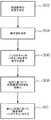
図3は、本発明の教示に従った、バックスキャッタパラメータを変化させる方法を示す流れ図である。第1のステップ、ステップ302において、RFIDリーダ102が周波数スペクトラムをスキャンして、RFIDタグのためにバックスキャッタリングの際に用いるための最適な周波数を決定する。バックスキャッタリングに用いるための最適な周波数の選択は、測定された様々な周波数の信号品質、一実施形態としては各周波数の信号対雑音比に基づいて行うことができる。他の実施形態では、RFIDタグ104に搬送波をバックスキャッタさせる周波数は、所望のデータ速度に基づいて決められる。ある種の変調方式では、データ速度およびバックスキャッタ変調された周波数の周波数は高くなる。さらに、使用する最適な周波数の選択は、他のバックスキャッタパラメータ、例えば変調形式などに少なくとも部分的に基づいて行うことができる。 FIG. 3 is a flow diagram illustrating a method for changing backscatter parameters in accordance with the teachings of the present invention. In the first step,
次に、ステップ304において、RFIDリーダ102はRFIDタグ104に電力を供給するために搬送波を送信する。上述のとおり、典型的な実施形態では、この搬送波がアンテナに交流電圧を誘導し、それは電圧整流器212によって直流電圧に変換される。直流電圧が十分なレベルに到達した後、RFIDタグ104が起動する。 Next, in
ステップ306において、RFIDリーダ102が、設定すべきバックスキャッタパラメータを表す信号を送信する。本発明の一実施形態では、この信号は、一以上のバックスキャッタパラメータを持つように選択される、状態機械218の状態を設定するために使用可能である。ある実施例では、バックスキャッタパラメータはバックスキャッタのために使用されるべき周波数とすることができる。ある実施例では、この信号は、RFIDタグ104に送信される任意の他のコマンドまたはデータとともに、コードとして送信することができる。他の実施例では、RFIDリーダ102は変更するべき他のバックスキャッタパラメータを示す信号を送信可能である。例えば、RFIDリーダ102は変調方式を変更するための信号を送信する。 In
次に、ステップ308では、一実施形態として、RFIDリーダ102から送信されるコマンドが、バックスキャッタパラメータを変更するために、状態機械の状態を切り替える。例えば、それぞれが異なったバックスキャッタ周波数を含む複数の状態が存在しうる。 Next, in
次に、ステップ310では、RFIDタグ104が、RFIDリーダ102の搬送波をバックスキャッタすることによって、RFIDリーダ102に応答する。本発明では、バックスキャッタは、少なくとも部分的には、RFIDリーダ102から送信されたバックスキャッタパラメータを用いて実行される。例えば、バックスキャッタは、RFIDリーダ102によって設定された周波数で実行される。これは、RFIDアンテナのインピーダンスを、RFIDリーダ102によって決定された必要な周波数を生成する、発振器215によって制御される速度で変化させることによって実行できる。他の実施例では、RFIDリーダ102によって設定された変調方式を用いてバックスキャッタを変調することができる。 Next, in
これまでの詳細な説明では少なくとも一つの実施形態を提示したが、非常に多くの変形例が存在しうることは理解できるであろう。ここで、上述の実施形態または実施例は例示に過ぎず、いかなる意味においても本発明の範囲、用途または構成を限定することを意図したものではない。むしろ、上述の詳細な説明は当業者に実施形態または実施例を具現化するための便利なロードマップを提供するものである。ここで、添付の特許請求の範囲によって定められる発明の技術的範囲およびそれらの法的均等物から乖離することなしに、要素の機能および配置における様々な変更が可能であることを理解できるであろう。 While at least one embodiment has been presented in the foregoing detailed description, it will be appreciated that a vast number of variations may exist. Here, the above-described embodiments or examples are merely examples, and are not intended to limit the scope, application, or configuration of the present invention in any way. Rather, the above detailed description provides those skilled in the art with a convenient road map for implementing an embodiment or example. It will now be understood that various changes in the function and arrangement of elements may be made without departing from the scope of the invention as defined by the appended claims and their legal equivalents. Let's go.
Claims (20)
Translated fromJapaneseRFIDリーダからの搬送波を受信可能なアンテナと、
前記アンテナに結合され、前記搬送波をバックスキャッタするのに使用する前記RFIDタグのためのバックスキャッタパラメータを含む、バックスキャッタコマンドを受信可能な状態機械と、
前記アンテナと前記状態機械との間に結合され、前記バックスキャッタパラメータに少なくとも部分的に基づいて形成された、変調されたバックスキャッタ信号を生成するように動作可能な変調器とを備える、RFIDタグ。An RFID tag,
An antenna capable of receiving a carrier wave from an RFID reader;
A state machine coupled to the antenna and capable of receiving backscatter commands, including backscatter parameters for the RFID tag used to backscatter the carrier;
An RFID tag coupled between the antenna and the state machine and operable to generate a modulated backscatter signal formed at least in part based on the backscatter parameter. .
ある周波数帯中の一以上の周波数の信号強度を決定する信号強度品質表示手段と、
前記信号強度回路の前記出力に基づいてコマンドを生成するプロセッサ手段と、
前記コマンドを含む信号を生成するためのトランシーバ手段とを備えるRFIDリーダ。An RFID reader for use in an RFID system,
Signal strength quality display means for determining the signal strength of one or more frequencies in a certain frequency band;
Processor means for generating a command based on the output of the signal strength circuit;
RFID reader comprising transceiver means for generating a signal including said command.
RFIDリーダから受信したコマンドに基づいて、バックスキャッタ変調信号設定を決定するステップと、
前記バックスキャッタ変調信号設定に少なくとも一部は基づいて、バックスキャッタ変調信号を生成するステップとを含む方法。A method of operating an RFID tag,
Determining a backscatter modulation signal setting based on a command received from the RFID reader;
Generating a backscatter modulation signal based at least in part on the backscatter modulation signal setting.
前記交流電圧を整流して直流電圧を生成するステップと、
少なくとも部分的に前記直流電圧によって前記RFIDタグに電力を供給するステップとをさらに含む、請求項16記載の方法。Inducing an alternating voltage from the received carrier wave;
Rectifying the AC voltage to generate a DC voltage;
17. The method of claim 16, further comprising powering the RFID tag at least in part by the DC voltage.
Applications Claiming Priority (2)
| Application Number | Priority Date | Filing Date | Title |
|---|---|---|---|
| US49884303P | 2003-08-29 | 2003-08-29 | |
| PCT/US2004/027999WO2005022454A1 (en) | 2003-08-29 | 2004-08-27 | Rfid system with selectable backscatter parameters |
Publications (2)
| Publication Number | Publication Date |
|---|---|
| JP2007504537Atrue JP2007504537A (en) | 2007-03-01 |
| JP2007504537A5 JP2007504537A5 (en) | 2007-10-18 |
Family
ID=34272738
Family Applications (1)
| Application Number | Title | Priority Date | Filing Date |
|---|---|---|---|
| JP2006524904APendingJP2007504537A (en) | 2003-08-29 | 2004-08-27 | RFID system with selectable backscatter parameters |
Country Status (8)
| Country | Link |
|---|---|
| US (1) | US20050052279A1 (en) |
| EP (1) | EP1665139A1 (en) |
| JP (1) | JP2007504537A (en) |
| KR (1) | KR20060038353A (en) |
| CN (1) | CN100530227C (en) |
| AU (1) | AU2004269728A1 (en) |
| CA (1) | CA2503407A1 (en) |
| WO (1) | WO2005022454A1 (en) |
Cited By (5)
| Publication number | Priority date | Publication date | Assignee | Title |
|---|---|---|---|---|
| JP2008228091A (en)* | 2007-03-14 | 2008-09-25 | Saxa Inc | Reader/writer device |
| JP2009033473A (en)* | 2007-07-27 | 2009-02-12 | Mitsubishi Electric Corp | Interference determination device, interference determination method, interference determination program, data reader, and RFID system |
| WO2012124166A1 (en)* | 2011-03-15 | 2012-09-20 | オムロン株式会社 | Rfid reader/writer, rfid system and communication method |
| US8319611B2 (en) | 2007-11-28 | 2012-11-27 | Renesas Electronics Corporation | Radio frequency indentification tag |
| WO2014156264A1 (en)* | 2013-03-29 | 2014-10-02 | 日立オートモティブシステムズ株式会社 | Cell system |
Families Citing this family (61)
| Publication number | Priority date | Publication date | Assignee | Title |
|---|---|---|---|---|
| US6933849B2 (en) | 2002-07-09 | 2005-08-23 | Fred Sawyer | Method and apparatus for tracking objects and people |
| JP3874007B2 (en)* | 2004-01-27 | 2007-01-31 | オムロン株式会社 | Read / write processing apparatus and read / write processing method for RFID tag |
| WO2005088850A1 (en)* | 2004-03-17 | 2005-09-22 | Brother Kogyo Kabushiki Kaisha | Position detection system, response device and query device, radio communication system, position detection method, position detection program, and information recording medium |
| US7388468B2 (en)* | 2004-04-13 | 2008-06-17 | Impinj, Inc. | Method and system to backscatter modulate a radio-frequency signal from an RFID tag in accordance with both an oscillation frequency signal and a command signal |
| US7917088B2 (en) | 2004-04-13 | 2011-03-29 | Impinj, Inc. | Adaptable detection threshold for RFID tags and chips |
| US7973643B2 (en)* | 2004-04-13 | 2011-07-05 | Impinj, Inc. | RFID readers transmitting preambles denoting data rate and methods |
| DE102004062364A1 (en)* | 2004-12-13 | 2006-06-14 | Atmel Germany Gmbh | Method for wireless data transmission |
| JP4873868B2 (en)* | 2005-02-09 | 2012-02-08 | ルネサスエレクトロニクス株式会社 | Passive RFID semiconductor device, IC tag, IC tag control method, and communication method |
| US8391785B2 (en)* | 2005-04-29 | 2013-03-05 | Impinj, Inc. | Interference rejection in RFID tags |
| US7489240B2 (en)* | 2005-05-03 | 2009-02-10 | Qualcomm, Inc. | System and method for 3-D position determination using RFID |
| US8477015B1 (en)* | 2005-05-05 | 2013-07-02 | National Semiconductor Corporation | System and method for using an input data signal as a clock signal in a RFID tag state machine |
| US7604178B2 (en)* | 2005-05-11 | 2009-10-20 | Intelleflex Corporation | Smart tag activation |
| WO2007035863A2 (en) | 2005-09-21 | 2007-03-29 | Intermec Ip Corp. | Radio frequency identification tags based on coalition formation |
| KR101276902B1 (en)* | 2006-03-31 | 2013-06-19 | 브리티쉬 텔리커뮤니케이션즈 파블릭 리미티드 캄퍼니 | Method and device for obtaining item information using rfid tags |
| US8120461B2 (en)* | 2006-04-03 | 2012-02-21 | Intermec Ip Corp. | Automatic data collection device, method and article |
| KR100817288B1 (en)* | 2006-08-25 | 2008-03-27 | 삼성전자주식회사 | Oscillator Tuning System and Oscillator Tuning Methods |
| KR100775213B1 (en) | 2006-10-19 | 2007-11-12 | 엘지이노텍 주식회사 | Tag recognition rate improvement system |
| US20080106410A1 (en)* | 2006-11-03 | 2008-05-08 | International Business Machines Corporation | System, method and program for monitoring rfid tags in a library |
| KR100853188B1 (en)* | 2006-12-08 | 2008-08-20 | 한국전자통신연구원 | Apparatus and method of power off in RFID system |
| KR100796011B1 (en)* | 2007-05-16 | 2008-01-21 | 쓰리에이로직스(주) | RF reader capable of detecting the presence of RF signal and contactless card and its method |
| US8552841B2 (en) | 2008-05-07 | 2013-10-08 | Infineon Technologies Ag | Communication method having selectable response signal strength levels |
| JP2010165191A (en)* | 2009-01-15 | 2010-07-29 | Fujitsu Ltd | Active tag apparatus, data reading/writing device, and system |
| KR100914850B1 (en)* | 2009-03-27 | 2009-09-02 | 주식회사 아이디로 | Back scattering type rfid communication system |
| CN102073834A (en)* | 2009-11-20 | 2011-05-25 | 数伦计算机技术(上海)有限公司 | Radio frequency identification system |
| US20120235799A1 (en)* | 2011-03-15 | 2012-09-20 | Omron Corporation | Rfid reader/writer, rfid system, and communication method |
| JP5490046B2 (en)* | 2011-03-22 | 2014-05-14 | 株式会社東芝 | Transmission equipment |
| CN102201071B (en)* | 2011-07-05 | 2014-02-26 | 上海天臣防伪技术股份有限公司 | A radio frequency identification tag chip suitable for multiple frequencies |
| US20130215979A1 (en)* | 2012-01-04 | 2013-08-22 | The Board Of Trustees Of The Leland Stanford Junior University | Method and Apparatus for Efficient Communication with Implantable Devices |
| CN102831448B (en)* | 2012-05-18 | 2015-09-09 | 睿芯联科(北京)电子科技有限公司 | A kind of rfid device |
| CN102752075B (en)* | 2012-05-21 | 2015-07-08 | 睿芯联科(北京)电子科技有限公司 | Radio frequency identifiable communication link rate adjusting method |
| KR20140066565A (en)* | 2012-11-23 | 2014-06-02 | 한국전자통신연구원 | Rfid tag including multi-voltage multiplier and operating method thereof |
| CN103198283A (en)* | 2013-04-23 | 2013-07-10 | 复旦大学 | Harmonic radio frequency identification system |
| CN103218653B (en)* | 2013-04-23 | 2016-03-30 | 复旦大学 | For label harmonic wave acquisition methods and the harmonic RF identification label of harmonic RF identification |
| US9814387B2 (en)* | 2013-06-28 | 2017-11-14 | Verily Life Sciences, LLC | Device identification |
| US9495567B2 (en) | 2013-12-30 | 2016-11-15 | Verily Life Sciences Llc | Use of a tag and reader antenna for a simulated theremin effect |
| US9973238B2 (en) | 2013-12-30 | 2018-05-15 | Verily Life Sciences, LLC | Methods for adjusting the power of an external reader |
| CN106031049B (en)* | 2013-12-30 | 2019-06-25 | 美卓流体控制有限公司 | Passive wireless sensor |
| US9818005B2 (en)* | 2014-06-13 | 2017-11-14 | Verily Life Sciences Llc | Zero-power wireless device programming |
| US9400904B2 (en) | 2014-06-13 | 2016-07-26 | Verily Life Sciences Llc | System for aligning a handheld RFID reader |
| CN104809421B (en)* | 2015-05-19 | 2018-06-19 | 沃科合众科技(北京)股份有限公司 | The method and apparatus of reading electronic labels |
| CN106485290B (en)* | 2015-08-24 | 2019-08-13 | 瑞章科技有限公司 | Enhance the device and method of tag backscatter energy |
| US10262172B1 (en) | 2015-09-29 | 2019-04-16 | Amazon Technologies, Inc. | Inventory tracking using RFID |
| US10089505B1 (en) | 2015-09-29 | 2018-10-02 | Amazon Technologies, Inc. | Inventory tracking using RFID |
| US10037449B1 (en) | 2015-09-29 | 2018-07-31 | Amazon Technologies, Inc. | Inventory tracking using RFID |
| CN106484109A (en)* | 2016-09-30 | 2017-03-08 | 西安交通大学 | A kind of gesture detecting method docking close-target object based on back-scattered signal |
| US9990518B2 (en) | 2016-11-04 | 2018-06-05 | Intermec, Inc. | Systems and methods for controlling radio-frequency indentification (RFID) tag communication |
| WO2018165146A1 (en) | 2017-03-06 | 2018-09-13 | Cummins Filtration Ip, Inc. | Genuine filter recognition with filter monitoring system |
| US10452968B2 (en) | 2017-06-14 | 2019-10-22 | Intermec, Inc. | Method to increase RFID tag sensitivity |
| US10430622B2 (en) | 2017-06-29 | 2019-10-01 | Intermec, Inc. | RFID tag with reconfigurable properties and/or reconfiguring capability |
| CN110324068A (en)* | 2018-03-28 | 2019-10-11 | 上海华为技术有限公司 | Radio frequency identification system, method for establishing relay network, reader and repeater |
| CN109412992B (en)* | 2018-11-13 | 2020-07-14 | 上海交通大学 | Backscattering system and method based on orthogonal frequency division multiple access technology |
| US11126905B2 (en)* | 2018-11-16 | 2021-09-21 | Georgia Tech Research Corporation | Antenna-less RFID tag |
| CN112423390B (en)* | 2019-08-21 | 2024-05-07 | 华为技术有限公司 | Method and apparatus for reflection communication |
| EP3816860B1 (en) | 2019-11-01 | 2023-01-18 | Nxp B.V. | Rfid transponder and method of operating an rfid transponder |
| EP3829028B1 (en)* | 2019-11-29 | 2023-07-12 | ElectDis AB | Method and devices for providing operational feedback during power transfer in a wireless power transfer system |
| US11290960B2 (en)* | 2020-02-10 | 2022-03-29 | Huawei Technologies Co., Ltd. | Method and apparatus for low power transmission using backscattering |
| US11457490B2 (en)* | 2020-05-29 | 2022-09-27 | Robert Bosch Gmbh | Backscatter communication system |
| WO2022222053A1 (en)* | 2021-04-20 | 2022-10-27 | Huawei Technologies Co., Ltd. | Multiple access in backscatter communication systems |
| CN117151130A (en)* | 2022-05-24 | 2023-12-01 | 维沃移动通信有限公司 | Backscatter signal transmission method, device, communication equipment and readable storage medium |
| CN118590348A (en)* | 2023-03-01 | 2024-09-03 | 维沃移动通信有限公司 | Tuning indication method, device and medium |
| WO2024222051A1 (en)* | 2024-01-10 | 2024-10-31 | Lenovo (Beijing) Limited | Carrier wave node determination |
Citations (3)
| Publication number | Priority date | Publication date | Assignee | Title |
|---|---|---|---|---|
| JPH0927773A (en)* | 1995-06-19 | 1997-01-28 | At & T Ipm Corp | Dual-mode modulation backscatter system |
| JPH09238115A (en)* | 1995-12-12 | 1997-09-09 | Lucent Technol Inc | Wireless communication system |
| JPH11191745A (en)* | 1997-12-25 | 1999-07-13 | Toshiba Corp | Information communication device, information communication system and information storage medium |
Family Cites Families (15)
| Publication number | Priority date | Publication date | Assignee | Title |
|---|---|---|---|---|
| US4075632A (en)* | 1974-08-27 | 1978-02-21 | The United States Of America As Represented By The United States Department Of Energy | Interrogation, and detection system |
| IL67379A (en)* | 1982-12-01 | 1985-11-29 | Tadiran Israel Elect Ind Ltd | Real-time frequency management system for hf communication networks |
| DE4003410A1 (en)* | 1990-02-05 | 1991-08-08 | Anatoli Stobbe | PORTABLE FIELD PROGRAMMABLE DETECTOR TAG |
| US5450088A (en)* | 1992-11-25 | 1995-09-12 | Texas Instruments Deutschland Gmbh | Transponder arrangement |
| US5396251A (en)* | 1992-12-15 | 1995-03-07 | Texas Instruments Deutschland Gmbh | Electronic transponder tuning procedure |
| US5375123A (en)* | 1993-02-05 | 1994-12-20 | Telefonakitebolaget L. M. Ericsson | Allocation of channels using interference estimation |
| US5517194A (en)* | 1994-02-10 | 1996-05-14 | Racom Systems, Inc. | Passive RF transponder and method |
| DE69516568T2 (en)* | 1994-03-04 | 2001-01-04 | Ncr International, Inc. | Extended wireless transmission system with modulated reflection |
| US6249212B1 (en)* | 1994-10-05 | 2001-06-19 | Avid Marketing, Inc. | Universal electronic identification tag |
| US5898928A (en)* | 1996-02-29 | 1999-04-27 | Telefonaktiebolaget Lm Ericsson | Adaptive frequency allocation in a telecommunication system |
| US5912632A (en)* | 1997-01-08 | 1999-06-15 | International Business Machines Corporation | Single chip RF tag oscillator circuit synchronized by base station modulation frequency |
| US7161476B2 (en)* | 2000-07-26 | 2007-01-09 | Bridgestone Firestone North American Tire, Llc | Electronic tire management system |
| US7054375B2 (en)* | 2000-12-22 | 2006-05-30 | Nokia Corporation | Method and apparatus for error reduction in an orthogonal modulation system |
| US6989750B2 (en)* | 2001-02-12 | 2006-01-24 | Symbol Technologies, Inc. | Radio frequency identification architecture |
| US6912832B1 (en)* | 2004-06-16 | 2005-07-05 | Vermeer Manufacturing Company | Mower suspension |
- 2004
- 2004-08-27JPJP2006524904Apatent/JP2007504537A/enactivePending
- 2004-08-27CNCNB2004800011725Apatent/CN100530227C/ennot_activeExpired - Fee Related
- 2004-08-27USUS10/927,775patent/US20050052279A1/ennot_activeAbandoned
- 2004-08-27EPEP04782471Apatent/EP1665139A1/ennot_activeWithdrawn
- 2004-08-27CACA002503407Apatent/CA2503407A1/ennot_activeAbandoned
- 2004-08-27AUAU2004269728Apatent/AU2004269728A1/ennot_activeAbandoned
- 2004-08-27KRKR1020057007371Apatent/KR20060038353A/ennot_activeCeased
- 2004-08-27WOPCT/US2004/027999patent/WO2005022454A1/enactiveApplication Filing
Patent Citations (3)
| Publication number | Priority date | Publication date | Assignee | Title |
|---|---|---|---|---|
| JPH0927773A (en)* | 1995-06-19 | 1997-01-28 | At & T Ipm Corp | Dual-mode modulation backscatter system |
| JPH09238115A (en)* | 1995-12-12 | 1997-09-09 | Lucent Technol Inc | Wireless communication system |
| JPH11191745A (en)* | 1997-12-25 | 1999-07-13 | Toshiba Corp | Information communication device, information communication system and information storage medium |
Cited By (7)
| Publication number | Priority date | Publication date | Assignee | Title |
|---|---|---|---|---|
| JP2008228091A (en)* | 2007-03-14 | 2008-09-25 | Saxa Inc | Reader/writer device |
| JP2009033473A (en)* | 2007-07-27 | 2009-02-12 | Mitsubishi Electric Corp | Interference determination device, interference determination method, interference determination program, data reader, and RFID system |
| US8319611B2 (en) | 2007-11-28 | 2012-11-27 | Renesas Electronics Corporation | Radio frequency indentification tag |
| WO2012124166A1 (en)* | 2011-03-15 | 2012-09-20 | オムロン株式会社 | Rfid reader/writer, rfid system and communication method |
| JP2012194696A (en)* | 2011-03-15 | 2012-10-11 | Omron Corp | Rfid reader/writer, rfid system, and communication method |
| WO2014156264A1 (en)* | 2013-03-29 | 2014-10-02 | 日立オートモティブシステムズ株式会社 | Cell system |
| JP2014197345A (en)* | 2013-03-29 | 2014-10-16 | 日立オートモティブシステムズ株式会社 | Battery system |
Also Published As
| Publication number | Publication date |
|---|---|
| EP1665139A1 (en) | 2006-06-07 |
| US20050052279A1 (en) | 2005-03-10 |
| CN1701342A (en) | 2005-11-23 |
| KR20060038353A (en) | 2006-05-03 |
| CA2503407A1 (en) | 2005-03-10 |
| WO2005022454A1 (en) | 2005-03-10 |
| CN100530227C (en) | 2009-08-19 |
| AU2004269728A1 (en) | 2005-03-10 |
Similar Documents
| Publication | Publication Date | Title |
|---|---|---|
| JP2007504537A (en) | RFID system with selectable backscatter parameters | |
| US7339481B2 (en) | RFID tag with tunable antenna and associated reader | |
| US10210445B2 (en) | Passive RFID sensor tag and RFID reader | |
| US9613237B2 (en) | Passive RFID sensor tag | |
| US20060267772A1 (en) | Mode-diveristy RFAID tag and interrogator system and method for identifying an RFAID transponder | |
| US9779342B2 (en) | RFID reading method and RFID reader | |
| JP6662843B2 (en) | Adaptive RFID reader | |
| US20080030324A1 (en) | Data communication with sensors using a radio frequency identification (RFID) protocol | |
| EP1431903B1 (en) | Detector | |
| US20180131542A1 (en) | Passive rfid sensor tag | |
| JP2001007730A (en) | Detection of distance from electromagnetic transponder | |
| EP1918861A2 (en) | Data carrier and data carrier system | |
| JP2008059244A (en) | Data carrier and data carrier system | |
| Vun et al. | Development of an embedded based rfid front end system |
Legal Events
| Date | Code | Title | Description |
|---|---|---|---|
| A521 | Request for written amendment filed | Free format text:JAPANESE INTERMEDIATE CODE: A523 Effective date:20070827 | |
| A621 | Written request for application examination | Free format text:JAPANESE INTERMEDIATE CODE: A621 Effective date:20070827 | |
| A977 | Report on retrieval | Free format text:JAPANESE INTERMEDIATE CODE: A971007 Effective date:20100520 | |
| A131 | Notification of reasons for refusal | Free format text:JAPANESE INTERMEDIATE CODE: A131 Effective date:20100602 | |
| A02 | Decision of refusal | Free format text:JAPANESE INTERMEDIATE CODE: A02 Effective date:20101104 |