JP2007503928A - Spinal deformity correction method using an anterior rod / plate system - Google Patents
Spinal deformity correction method using an anterior rod / plate systemDownload PDFInfo
- Publication number
- JP2007503928A JP2007503928AJP2006525462AJP2006525462AJP2007503928AJP 2007503928 AJP2007503928 AJP 2007503928AJP 2006525462 AJP2006525462 AJP 2006525462AJP 2006525462 AJP2006525462 AJP 2006525462AJP 2007503928 AJP2007503928 AJP 2007503928A
- Authority
- JP
- Japan
- Prior art keywords
- anterior
- screw
- hole
- spinal
- plate
- Prior art date
- Legal status (The legal status is an assumption and is not a legal conclusion. Google has not performed a legal analysis and makes no representation as to the accuracy of the status listed.)
- Granted
Links
Images


Classifications
- A—HUMAN NECESSITIES
- A61—MEDICAL OR VETERINARY SCIENCE; HYGIENE
- A61B—DIAGNOSIS; SURGERY; IDENTIFICATION
- A61B17/00—Surgical instruments, devices or methods
- A61B17/56—Surgical instruments or methods for treatment of bones or joints; Devices specially adapted therefor
- A61B17/58—Surgical instruments or methods for treatment of bones or joints; Devices specially adapted therefor for osteosynthesis, e.g. bone plates, screws or setting implements
- A61B17/68—Internal fixation devices, including fasteners and spinal fixators, even if a part thereof projects from the skin
- A61B17/70—Spinal positioners or stabilisers, e.g. stabilisers comprising fluid filler in an implant
- A61B17/7001—Screws or hooks combined with longitudinal elements which do not contact vertebrae
- A61B17/7044—Screws or hooks combined with longitudinal elements which do not contact vertebrae also having plates, staples or washers bearing on the vertebrae
- A—HUMAN NECESSITIES
- A61—MEDICAL OR VETERINARY SCIENCE; HYGIENE
- A61B—DIAGNOSIS; SURGERY; IDENTIFICATION
- A61B17/00—Surgical instruments, devices or methods
- A61B17/56—Surgical instruments or methods for treatment of bones or joints; Devices specially adapted therefor
- A61B17/58—Surgical instruments or methods for treatment of bones or joints; Devices specially adapted therefor for osteosynthesis, e.g. bone plates, screws or setting implements
- A—HUMAN NECESSITIES
- A61—MEDICAL OR VETERINARY SCIENCE; HYGIENE
- A61B—DIAGNOSIS; SURGERY; IDENTIFICATION
- A61B17/00—Surgical instruments, devices or methods
- A61B17/56—Surgical instruments or methods for treatment of bones or joints; Devices specially adapted therefor
- A—HUMAN NECESSITIES
- A61—MEDICAL OR VETERINARY SCIENCE; HYGIENE
- A61B—DIAGNOSIS; SURGERY; IDENTIFICATION
- A61B17/00—Surgical instruments, devices or methods
- A61B17/56—Surgical instruments or methods for treatment of bones or joints; Devices specially adapted therefor
- A61B17/58—Surgical instruments or methods for treatment of bones or joints; Devices specially adapted therefor for osteosynthesis, e.g. bone plates, screws or setting implements
- A61B17/68—Internal fixation devices, including fasteners and spinal fixators, even if a part thereof projects from the skin
- A61B17/70—Spinal positioners or stabilisers, e.g. stabilisers comprising fluid filler in an implant
- A61B17/7001—Screws or hooks combined with longitudinal elements which do not contact vertebrae
- A61B17/7002—Longitudinal elements, e.g. rods
- A61B17/7004—Longitudinal elements, e.g. rods with a cross-section which varies along its length
- A61B17/7007—Parts of the longitudinal elements, e.g. their ends, being specially adapted to fit around the screw or hook heads
- A—HUMAN NECESSITIES
- A61—MEDICAL OR VETERINARY SCIENCE; HYGIENE
- A61B—DIAGNOSIS; SURGERY; IDENTIFICATION
- A61B17/00—Surgical instruments, devices or methods
- A61B17/56—Surgical instruments or methods for treatment of bones or joints; Devices specially adapted therefor
- A61B17/58—Surgical instruments or methods for treatment of bones or joints; Devices specially adapted therefor for osteosynthesis, e.g. bone plates, screws or setting implements
- A61B17/68—Internal fixation devices, including fasteners and spinal fixators, even if a part thereof projects from the skin
- A61B17/70—Spinal positioners or stabilisers, e.g. stabilisers comprising fluid filler in an implant
- A61B17/7001—Screws or hooks combined with longitudinal elements which do not contact vertebrae
- A61B17/7002—Longitudinal elements, e.g. rods
- A61B17/701—Longitudinal elements with a non-circular, e.g. rectangular, cross-section
- A—HUMAN NECESSITIES
- A61—MEDICAL OR VETERINARY SCIENCE; HYGIENE
- A61B—DIAGNOSIS; SURGERY; IDENTIFICATION
- A61B17/00—Surgical instruments, devices or methods
- A61B17/56—Surgical instruments or methods for treatment of bones or joints; Devices specially adapted therefor
- A61B17/58—Surgical instruments or methods for treatment of bones or joints; Devices specially adapted therefor for osteosynthesis, e.g. bone plates, screws or setting implements
- A61B17/68—Internal fixation devices, including fasteners and spinal fixators, even if a part thereof projects from the skin
- A61B17/70—Spinal positioners or stabilisers, e.g. stabilisers comprising fluid filler in an implant
- A61B17/7001—Screws or hooks combined with longitudinal elements which do not contact vertebrae
- A—HUMAN NECESSITIES
- A61—MEDICAL OR VETERINARY SCIENCE; HYGIENE
- A61B—DIAGNOSIS; SURGERY; IDENTIFICATION
- A61B17/00—Surgical instruments, devices or methods
- A61B17/56—Surgical instruments or methods for treatment of bones or joints; Devices specially adapted therefor
- A61B17/58—Surgical instruments or methods for treatment of bones or joints; Devices specially adapted therefor for osteosynthesis, e.g. bone plates, screws or setting implements
- A61B17/68—Internal fixation devices, including fasteners and spinal fixators, even if a part thereof projects from the skin
- A61B17/70—Spinal positioners or stabilisers, e.g. stabilisers comprising fluid filler in an implant
- A61B17/7059—Cortical plates
Landscapes
- Health & Medical Sciences (AREA)
- Orthopedic Medicine & Surgery (AREA)
- Surgery (AREA)
- Life Sciences & Earth Sciences (AREA)
- Neurology (AREA)
- Medical Informatics (AREA)
- Biomedical Technology (AREA)
- Heart & Thoracic Surgery (AREA)
- Engineering & Computer Science (AREA)
- Molecular Biology (AREA)
- Animal Behavior & Ethology (AREA)
- General Health & Medical Sciences (AREA)
- Public Health (AREA)
- Veterinary Medicine (AREA)
- Nuclear Medicine, Radiotherapy & Molecular Imaging (AREA)
- Prostheses (AREA)
- Surgical Instruments (AREA)
Abstract
Translated fromJapaneseDescription
Translated fromJapanese本発明は、頭方向端および尾方向端の椎骨における2枚の脊椎プレートをロッド式前方システムと組み合わすことができる前方脊椎器具システム(ロッド/プレート前方システム)に関する。ロッド/プレート前方システムは、胸腰椎および腰椎の側弯症ならびに脊椎安定化を要する他の状態を外科的に処置するために用いるものである。 The present invention relates to an anterior spinal instrument system (rod / plate anterior system) that can combine two spinal plates at the vertebrae at the cranial end and the caudal end with a rod-type anterior system. The rod / plate anterior system is used to surgically treat thoracolumbar and lumbar scoliosis and other conditions that require spinal stabilization.
ドワイヤー(Dwyer)が、1969年に最初に前方脊椎固定のための脊椎器具システムを導入した。ドワイヤーのシステムは、ねじおよび柔軟なケーブルを使用するものであったが、このシステムは、一方の椎体を他方の椎体に押し付ける効果によって限定的な安定性を与えるだけであった。柔軟なケーブルは張力に耐えるのみであり、ドワイヤーのシステムは椎骨間を剛性連結できず、しばしばケーブルまたはねじの不具合を招いて爾後に偽関節症を伴うことになった。1976年に、ツィールケ(Zielke)がケーブルの代わりに小径ねじ付きロッドおよびナットを用いることによってドワイヤーのシステムを改良し、回旋矯正および脊柱後弯防止のために設計された減捻具を導入した。長年に亘って、胸腰椎および腰椎の側弯症を処置するためのツィールケ器具使用手法は、冠状湾曲の効果的な矯正能力、脊柱のより短い区間に器具を使用することによる変形矯正能力、およびその減捻能力の点で、ドワイヤーのシステムに対してかなりの利点を有することが認められた。しかし、ツィールケのシステムには、インプラント破損の高い発生率、矯正の喪失、脊柱後弯の進行、および相対的に小径のロッドの区間の剛性不足によって主として生じる偽関節症を伴うことが報告されてきた。 Dwyer first introduced a spinal instrument system for anterior spinal fixation in 1969. The Dwyer system used screws and flexible cables, but this system only provided limited stability by the effect of pressing one vertebral body against the other. Flexible cables can only withstand tension, and the dwyer system cannot rigidly connect between the vertebrae, often resulting in cable or screw failure resulting in pseudoarthritis after drought. In 1976, Zielke improved the dwyer system by using small-diameter threaded rods and nuts instead of cables, and introduced a reducer designed for convolution and spinal kyphosis prevention. For many years, the Tielke instrumentation approach to treat thoracolumbar and lumbar scoliosis has been an effective ability to correct coronary curvature, the ability to correct deformation by using instruments in shorter sections of the spine, and its It has been found that there are significant advantages over the dwyer system in terms of ability to reduce twist. However, Tielke's system has been reported to involve pseudoarthropathy, mainly caused by a high incidence of implant failure, loss of correction, progression of kyphosis, and lack of stiffness in the relatively small diameter rod section. It was.
1989年に、より大径の中実ロッドシステムがTSRHによって導入されると、より大径のロッドの適切な外形および回旋によって、器具使用区間の脊柱前弯を創出できるようになった。ドワイヤーまたはツィールケのシステムの長手部材の剛性よりも300%から400%剛性が増大した6.4mmのロッドが、外部から固定しなくても、矯正を維持しながら固定率を増大させるのに十分な剛性を与えることが想定された。しかし、このような器具使用によって処置された症例を調べると、ドワイヤーまたはツィールケに較べると改善は見られたが、前面および矢状面における矯正喪失の発生率は依然として許容できないものであった。 In 1989, when a larger diameter solid rod system was introduced by TSRH, the proper contour and rotation of the larger diameter rod allowed the creation of a lordosis of the instrument use section. A 6.4 mm rod with 300% to 400% greater stiffness than the longitudinal member of the dwyer or tielke system is sufficient to increase the fixation rate while maintaining straightening, even without external fixation. It was assumed to give rigidity. However, when examining cases treated with such devices, improvements were seen compared to Dwyer or Tielke, but the incidence of loss of correction in the front and sagittal planes was still unacceptable.
幾人かの著者が、頭方向端の椎骨ねじおよび尾方向端の椎骨ねじの骨/ねじ境界面における、かなり大きな歪力を記述した。1本ロッド器具使用区間における矯正喪失および脊柱後弯は、特に、頭方向および尾方向の境界面における骨/ねじ境界面の弛みの結果として、恐らくは不十分な構造的剛性が原因で術後早期に生じたものである。剛性1本ロッドは、術後早期では変形脊柱の矯正に十分な安定性を与えることができる。しかし、それは日常活動の間に骨/ねじ境界面でそれぞれのねじの軸回りに椎骨が回旋するのを防止することができない。その理由は恐らく、中実1本ロッドシステムには、特に、器具使用区間の頭方向および尾方向の最端の椎骨において、それぞれの椎骨上に固定点が2つ存在しないことである。 Several authors have described significant strain at the bone / screw interface at the vertebral screw at the cranial end and at the caudal end. Loss of correction and kyphosis in the single rod instrument use section are prematurely postoperative, possibly due to insufficient structural stiffness, possibly as a result of loosening of the bone / screw interface at the head and tail interface This is what happened. A single rigid rod can provide sufficient stability to correct the deformed spine early in the surgery. However, it cannot prevent rotation of the vertebra around the axis of each screw at the bone / screw interface during daily activities. The reason is probably that the solid single rod system does not have two fixation points on each vertebra, especially at the extreme vertebrae in the head and tail directions of the instrument use section.
1996年に、カネダ(Kaneda)が、胸腰椎および腰椎の側弯症を処置するために、それぞれの椎骨上に2つの固定点を有する2本ロッド前方システム(KASS)を導入した。それは当該問題の解答であるように思われ、これらの端部の椎骨が回旋して脊柱後弯になるのを防止する。この技法は、早期の術後観察期間では良好な結果で推移した。しかし、このシステムは、高い突出輪郭を有し、しかも重度に変形した脊柱に応用することが難しいので、用いるには幾つかの制約がある。 In 1996, Kaneda introduced a two-rod anterior system (KASS) with two fixation points on each vertebra to treat thoracolumbar and lumbar scoliosis. It seems to be the answer to the problem and prevents these end vertebrae from turning into kyphosis. This technique performed well in the early postoperative observation period. However, this system has some limitations in use because it has a high protruding profile and is difficult to apply to a heavily deformed spine.
本発明者は、剛性1本ロッド構造を埋植するという相対的な容易さと、それぞれの端部の椎骨上の2つの固定点とを組み合わせるために、中実1本ロッド前方システム(TSRH)を改良し、しかも器具使用区間の頭方向端および尾方向端の椎骨における脊椎プレート固定を可能にするロッド/プレート前方システムを開発した。 In order to combine the relative ease of implanting a rigid single rod structure with the two fixation points on the vertebra at each end, the inventor has developed a solid single rod anterior system (TSRH). An improved rod / plate anterior system has been developed that allows for spinal plate fixation at the vertebrae at the head and tail ends of the instrument use section.
本発明は、器具使用区間の頭方向端および尾方向端の椎骨で脊椎プレート固定を可能にするために剛性1本ロッド前方システムを改良したロッド/プレート脊柱前方器具システムを提供する。本開示は、骨インプラントの強度および安定性を増大させるために、ロッド式前方器具の相対的な利点をプレートと組み合わせる。 The present invention provides a rod / plate anterior instrument system that improves on the rigid single rod anterior system to allow spinal plate fixation at the vertebrae at the head and tail ends of the instrument use section. The present disclosure combines the relative advantages of a rod-type anterior instrument with a plate to increase the strength and stability of the bone implant.
本発明は、より少ない部品点数およびより低い輪郭、脊柱変形に対する適応性、重度変形脊柱に対するインプラントの応用容易性、最終ねじの尾方向の円板の楔状化および/または劣化を回避するための端部椎骨の調節容易性、胸椎から腰椎に及ぶ使用可能性、手術回数の削減、ならびに手術過程の簡素化を含めて、2本ロッド式システムに優る数多くの利点を提供する。 The present invention reduces the number of parts and lower contours, adaptability to spinal deformities, ease of application of implants to severely deformed spines, end to avoid wedge-shaped and / or degradation of the disc in the tail direction of the final screw. It offers a number of advantages over the two-rod system, including ease of adjustment of the cervical vertebrae, feasibility of use from the thoracic vertebrae to the lumbar spine, reducing the number of operations, and simplifying the surgical process.
好ましい実施形態では、本発明は凸側および凹側を有する脊柱の変形部を治療する前方脊椎器具取付け方法を含み、本方法は、
変形部の凸側で、2枚の脊椎プレートを頭方向端および尾方向端の椎骨にそれぞれ装着するステップと、
凸側の後方部分上にロッド前方システムを固定するステップと、を含む。2枚の脊椎プレートは、1本ロッド前方システムの椎骨ねじによって、頭方向最端および尾方向最端の椎骨上に装着され、脊柱の変形部は、ロッド前方システムの圧縮、伸延、および減捻によって矯正される。本方法は、ロッド脊椎器具に連結される脊椎プレートを介して、凸側の前方部分で、幾本かの海綿質ねじを頭方向端および尾方向端の椎骨およびそれらに隣接する椎骨の中に螺入するステップをさらに含み得る。In a preferred embodiment, the present invention includes an anterior spinal instrument attachment method for treating a spinal deformity having a convex side and a concave side, the method comprising:
Attaching the two spinal plates to the vertebrae at the head end and the tail end on the convex side of the deformed portion,
Securing the rod front system on the convex rear portion. The two spinal plates are mounted on the vertebrae at the headmost and caudal end by vertebral screws of the single rod anterior system, and the spinal deformities are compressed, distracted and reduced by the rod anterior system Is corrected by. The method uses a spinal plate connected to a rod spinal instrument to place several cancellous screws into the vertebrae at the cranial and caudal ends and adjacent vertebrae at the convex anterior portion. A screwing step may further be included.
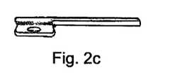
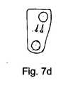
この好ましい方法は少なくとも2つの椎骨を連結する「L字」形の脊椎プレートも含む。これは、第1の端部および第2の端部を備え、第1の端部は長手部分を有し、且つ2つの椎骨間を差し渡すのに十分な長さを有する。この長手部分は、プレートが椎骨に装着可能であるようにねじを受け入れるための一連の開口を有する細長い溝穴を有する。これらの開口は、所望の椎骨上に力伝達部材を位置決め可能にし、かつ脊椎プレートを異なる大きさの椎骨で使用可能にする。 This preferred method also includes an “L” shaped spinal plate connecting at least two vertebrae. This comprises a first end and a second end, the first end having a longitudinal portion and sufficient length to pass between the two vertebrae. The longitudinal portion has an elongated slot with a series of openings for receiving screws so that the plate can be attached to the vertebra. These openings allow the force transmission member to be positioned over the desired vertebra and allow the spinal plate to be used with different sized vertebrae.
第2の端部は、長手部分に直角の横部分を有する。この横部分は、椎骨の横側と前/後方向で一体になる。上/下方向では、終板突起を回避し、かつプレートが骨に密着するようにプレートの厚さが小さくなる。横部分は、前方領域中に第1の穴を有し、かつ後方領域中に第2の穴を有する。第2の穴は上/下方向の中点に配置され、それは脊椎ねじが安全に中心位置にあることを示す。第1の穴は、中心に向かって角度が付けられ、大動脈の損傷および椎体前縁の破損を回避するためにねじを後方向に螺入できるようにする。2穴設計は、2本のねじと脊椎プレートの横部分との間で、椎骨中に安定した3角形ねじ構造を設ける。脊椎プレートが様々な脊柱変形部に対応できるように、脊椎プレートの長手部分と横部分との間は80°から100°までの様々な角度で設計される。脊椎プレートが少なくとも2つの椎骨間を差し渡すことができるように、脊椎プレートの長手部分は様々な長さで設計される。 The second end has a transverse portion perpendicular to the longitudinal portion. This lateral portion is integral with the lateral side of the vertebra in the anterior / posterior direction. In the up / down direction, the plate thickness is reduced to avoid endplate protrusions and to adhere the plate to the bone. The lateral portion has a first hole in the front region and a second hole in the rear region. The second hole is located at the midpoint in the up / down direction, which indicates that the spinal screw is safely in the center position. The first hole is angled toward the center, allowing the screw to be screwed back to avoid aortic damage and anterior vertebral body breakage. The two-hole design provides a stable triangular screw structure in the vertebra between the two screws and the lateral portion of the spinal plate. The longitudinal and lateral portions of the spinal plate are designed at various angles from 80 ° to 100 ° so that the spinal plate can accommodate various spinal deformities. The longitudinal portion of the spinal plate is designed with various lengths so that the spinal plate can pass between at least two vertebrae.
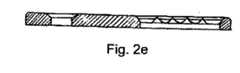
脊椎プレートは、その下側表面および上側表面では、脊椎に面する下側表面を有する。長手部分には、複数の細歯が溝穴に沿って形成される。これらの細歯は、脊椎プレートが椎骨に対して滑動するのを防止する。脊椎プレートは、それが解剖学的な最適取付けのために椎骨の解剖学的構造に一致し、かつ前/後方向の構造輪郭を最小化するように、横方向に形状がわずかに凹である。長手部分の上表面では、海綿質ねじ頭部の下部丸味表面と同じ角度で傾斜する斜めの上縁部分または外縁部分が溝穴に設けられる。海綿質ねじの下部丸味表面に係合するように、複数の凹部が斜めの縁部に設けられる。これらの凹部は、ねじが脊椎プレートに対して横移動しないようにねじを保持する。これらの凹部は、ねじ頭部の下部丸味表面と同じ挟角を有する円錐の一部を構成する表面によって画成される。横部分では、前方穴に斜めの上縁部分が設けられ、その縁部分はねじ頭部の下部丸味表面と同じ角度で傾斜する。横部分の上側表面は、それが椎骨の解剖学的構造と一致するように前/後方向に僅かに凸面である。 The spinal plate has a lower surface facing the spine at its lower and upper surfaces. In the longitudinal portion, a plurality of fine teeth are formed along the slot. These fine teeth prevent the spinal plate from sliding relative to the vertebra. The spinal plate is slightly concave in shape laterally so that it conforms to the vertebral anatomy for optimal anatomical attachment and minimizes anterior / posterior structural contours . On the upper surface of the longitudinal portion, an oblique upper edge portion or outer edge portion inclined at the same angle as the lower round surface of the cancellous screw head is provided in the slot. A plurality of recesses are provided at the diagonal edges to engage the lower rounded surface of the sponge screw. These recesses hold the screws so that they do not move laterally with respect to the spinal plate. These recesses are defined by a surface that forms part of a cone having the same included angle as the lower rounded surface of the screw head. In the lateral part, the front hole is provided with an oblique upper edge part, which edge part is inclined at the same angle as the lower rounded surface of the screw head. The upper surface of the transverse portion is slightly convex in the anterior / posterior direction so that it matches the vertebral anatomy.
海綿質ねじはまた、その上に海綿質ねじ山を有する骨係合部分と頭部とを具備し得る。頭部は、下部丸味表面および上部丸味表面を具備する。概ね円筒形の部分が、下部丸味表面と上部丸味表面とを分離する。ねじ頭部は工具係合凹部も具備する。工具係合凹部は任意適切な構成でよく、6角形、6耳状、または他の任意適切な構成を含む。ロッド前方システムは、TSRH、CDH、マイアミ(Miami)、または他のいずれかを含めて、任意適切な1本ロッド前方システムでよい。 The cancellous screw may also comprise a bone engaging portion having a cancellous thread thereon and a head. The head has a lower rounded surface and an upper rounded surface. A generally cylindrical portion separates the lower rounded surface and the upper rounded surface. The screw head also includes a tool engaging recess. The tool engagement recess may be of any suitable configuration, including hexagonal, hexalobe, or any other suitable configuration. The rod forward system may be any suitable single rod forward system, including TSRH, CDH, Miami, or any other.
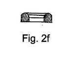
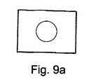
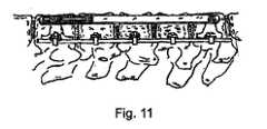
好ましい方法の実施では、脊椎プレートは、1対の同じような上下椎骨ステープルを介して少なくとも2つの椎骨を連結する長方形とすることができ、それは第1および第2の端部を有する。第1の端部は第1の穴を有し、第2の端部は細長いu字形溝穴を有する。このプレートはまた、下側表面(ねじに面する側)および上側表面(ワッシャーに面する側)を含む。下側表面で、第1の穴は、脊椎プレートが様々な角度配置で海綿質ねじに取り付き得るように、穴の回りに径方向へ延びる複数の細歯を画成する。上側表面で、細長いu字形溝穴は、脊椎プレートが矩形の細歯付きワッシャーを介して、隣接する骨ねじと適合するために可変位置で配置可能であるように複数の平行な細歯を画定する。このプレートを使用して、1対の同じような上下椎骨ステープルを器具使用区間の両端の椎骨に装着することができる。これらの椎骨ステープルは、後方穴および前方穴を有する。後方穴は前方ロッド式システムのねじを受け入れ、前方穴は脊椎プレートを固定するための海綿質ねじを受け入れる。椎骨ステープルは楔形であり、脊椎ねじによって1対の金属製の緊張ケーブルを椎骨に固定することが可能である。ステープルは3つの突出部を含むことが好ましい。1対の実質的に平行な、垂直にオフセットした薄板後方足部が、椎骨終板の中に挿入され、該後方足部の間の平行距離は、椎骨の両側を覆ってぴったりとフィットするようになっている。第3の突出部は、大動脈および胸/腹部器官の損傷を回避するためにステープルの中心部に配置される。ステープルは1対の脊椎ねじ受け穴をさらに具備し得る。後方穴は2つの後方ステープル足部間の中間部分に配置され、この穴は脊椎ねじを安全に中間部分に位置決めする。前方穴はステープルの前方部分の中心に向かって傾斜する。前方穴は、大動脈の損傷および椎体前縁の破損を回避するように、適切な梃子作用で幾何学的に前方ねじを後方に向けさせる。後方穴は、脊髄の損傷を回避するように、後方椎骨ねじを前方に向けさせる。2穴設計は、2本のねじとステープルとの間で椎骨中に安定性のある3角形ねじ構造を設ける。ステープルは、それが解剖学的に最適に取り付けられ、前/後方向の構造輪郭を最小にするために椎骨の解剖学的構造に一致するように、形状が僅かに凸である、一体の実質的に中実で楔形の薄板架橋部分をさらに含む。上/下方向の部分は、終板突起を回避しかつプレートが骨に密着するように、2つの後方足部よりも幅が狭い。 In a preferred method implementation, the spinal plate can be rectangular that connects at least two vertebrae via a pair of similar upper and lower vertebral staples, which have first and second ends. The first end has a first hole and the second end has an elongated u-shaped slot. The plate also includes a lower surface (side facing the screw) and an upper surface (side facing the washer). On the lower surface, the first hole defines a plurality of fine teeth that extend radially around the hole so that the spinal plate can attach to the cancellous screw in various angular arrangements. On the upper surface, the elongated u-shaped slot defines a plurality of parallel fine teeth so that the spinal plate can be placed in variable positions to fit adjacent bone screws via rectangular fine tooth washers To do. Using this plate, a pair of similar upper and lower vertebral staples can be attached to the vertebrae at both ends of the instrument use section. These vertebral staples have a posterior hole and an anterior hole. The posterior hole accepts an anterior rod system screw and the anterior hole accepts a cancellous screw for securing the spinal plate. Vertebral staples are wedge shaped and a pair of metal tension cables can be secured to the vertebrae by spinal screws. The staple preferably includes three protrusions. A pair of substantially parallel, vertically offset lamellar posterior feet are inserted into the vertebral endplate so that the parallel distance between the posterior feet fits snugly on both sides of the vertebra. It has become. The third protrusion is placed in the center of the staple to avoid damage to the aorta and thoracic / abdominal organs. The staple may further comprise a pair of spinal screw receiving holes. The posterior hole is located in the middle part between the two posterior staple legs, and this hole safely positions the spinal screw in the middle part. The forward hole is inclined toward the center of the forward portion of the staple. The anterior hole geometrically directs the anterior screw backwards with appropriate lever action to avoid aortic damage and vertebral anterior rupture. The posterior hole directs the posterior vertebral screw forward so as to avoid spinal cord damage. The two-hole design provides a stable triangular screw structure in the vertebra between the two screws and staples. The staple is a unitary substance that is slightly convex in shape so that it is optimally anatomically attached and conforms to the vertebral anatomy to minimize anterior / posterior structural contours It further includes a solid, wedge-shaped thin plate bridging portion. The upper / lower portion is narrower than the two posterior feet so as to avoid endplate protrusions and to keep the plate in close contact with the bone.
ねじを螺入する穴を開けるべき型板として、椎骨ステープルは、ねじ引抜き力を増加し、ねじの移動およびねじの引抜きを防止する上で非常に効果的であることが分かっている。様々な寸法および形状は、側方プレートを腰椎または胸椎に取り付けできるように、椎骨の多様な解剖学的形状に対応する。 As a template to be pierced with screws, vertebral staples have been found to be very effective in increasing screw withdrawal force and preventing screw movement and screw withdrawal. The various dimensions and shapes correspond to the various anatomical shapes of the vertebra so that the lateral plate can be attached to the lumbar or thoracic vertebrae.
好ましい方法では、海綿質ねじは、ステープルの前方穴を介して矩形の脊椎プレートを受けることができ、第1の端部および第2の端部を有する。第1の端部は螺入先端を有し、この螺入先端から海綿質のねじ山が第1の端部の実質的な部分に沿って延びる。第2の端部は、前記第1の端部から外向きに延びる突出軸として画成され、前記突出軸の少なくとも一部にねじ山が付けられている。この突出軸は、第1の端部と同じ直径を有する。第2の端部は工具係合凹部も具備する。この工具係合凹部は任意適切な構成でよく、6角形、6耳状、または他の任意の構成を含む。壁接合部が、第1の端部と第2の端部との間に形成される。海綿質ねじ最端部では、壁接合部の上表面に径方向の細歯が存在するが、隣接する海綿質ねじ最端部では、壁接合部の平滑な上表面が存在する。これらの径方向の細歯は、脊椎プレートを隣接する椎骨ねじに適合させる。 In a preferred method, the cancellous screw can receive a rectangular spinal plate via the anterior hole of the staple and has a first end and a second end. The first end has a threaded tip from which a spongy thread extends along a substantial portion of the first end. The second end portion is defined as a protruding shaft extending outward from the first end portion, and at least a part of the protruding shaft is threaded. The protruding shaft has the same diameter as the first end. The second end also includes a tool engaging recess. The tool engaging recess may be of any suitable configuration, including hexagonal, hexalobe, or any other configuration. A wall joint is formed between the first end and the second end. At the end of the cancellous screw, there are radial fine teeth on the upper surface of the wall joint, but at the adjacent end of the cancellous screw, there is a smooth upper surface of the wall joint. These radial fine teeth adapt the spinal plate to adjacent vertebral screws.
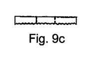
好ましい方法は、矩形の細歯付きワッシャーが、複数の平行細歯によって画成された下側表面を有する矩形の細歯ワッシャーであり、このワッシャーが、前方ねじを固定するように側方プレートに取り付き得るようになっている実施形態も含み得る。上側表面は、締付けナットを受けるように平滑でよく、ワッシャーはさらに、このワッシャーの中心部に穴を具備し得る。矩形の脊椎プレートは、器具使用区間の頭方向椎骨から尾方向椎骨までもより多くの椎骨を網羅するのに十分な長さも有することができる。 A preferred method is that the rectangular fine tooth washer is a rectangular fine tooth washer having a lower surface defined by a plurality of parallel fine teeth, which is attached to the side plate to secure the front screw. Embodiments adapted for attachment may also be included. The upper surface may be smooth to receive the clamping nut and the washer may further comprise a hole in the center of the washer. The rectangular spine plate may also have a length sufficient to cover more vertebrae from the head vertebra to the caudal vertebra in the instrument use section.
Claims (19)
Translated fromJapanese前記変形部の前記凸側で、2枚の脊椎プレートを頭方向端および尾方向端の椎骨にそれぞれ装着するステップと、
前記凸側の後方部分にロッド前方システムを固定するステップであって、前記1本ロッド前方システムの椎骨ねじによって、第1の脊椎プレートが頭方向最端の椎骨に装着され、かつ第2の脊椎プレートが尾方向最端の椎骨に装着される、ステップと、
前記ロッド前方システムの圧縮、伸延、および/または減捻によって、前記脊柱の前記変形部を矯正するステップと、
前記ロッド脊柱器具に連結される前記脊椎プレートを介して、前記凸側の前方部分で、複数の海綿質ねじを上記頭方向端および上記尾方向端の椎骨ならびにそれらに隣接する椎骨に螺入するステップと、
を含む方法。An anterior spinal instrument use method of treating a spinal deformity having a convex side and a concave side, the method comprising:
Attaching two spinal plates to the vertebrae at the head end and the tail end at the convex side of the deformable portion,
Securing a rod anterior system to the convex posterior portion, wherein a vertebral screw of the one-rod anterior system attaches a first spinal plate to the headmost vertebra and a second spine A plate is attached to the vertebra at the end of the caudal direction, and
Correcting the deformed portion of the spinal column by compression, distraction and / or reduction of the anterior rod system;
Via the spinal plate connected to the rod spinal instrument, at the convex anterior portion, a plurality of cancellous screws are screwed into the cranial and caudal vertebrae and adjacent vertebrae. Steps,
Including methods.
第1の端部、第2の端部、上記椎骨に面する下表面、ならびに上表面を有し、
前記第1の端部は長手部分を有し、且つ2つの椎骨間をさし渡すのに十分な長さを有し、前記長手部分は前記プレートが上記椎骨に装着可能であるようにねじを受け入れるための一連の開口を提供する細長い溝穴を具備し、前記開口は所望の前記椎骨上に前記ねじを位置決め可能にし且つ異なる大きさの椎骨に対応するように構成され、前記脊椎プレートが上記椎骨に対して滑動するのを防止するように構成された複数の細歯が、前記溝穴の底部分に沿って形成され、前記溝穴の斜めの上縁部分または下縁部分が海綿質ねじの頭部の下部丸味表面に共形であり、複数の凹部が、前記脊椎プレートに対して前記ねじが横方向に移動しないように効果的に保持するために、前記海綿質ねじの前記下部丸味表面に係合するように前記斜めの縁部に設けられ、前記凹部は、前記ねじの前記頭部の前記下部丸味表面と同じ挟角を有する円錐の一部を形成する表面によって画成され、
前記第2の端部は、使用時に前記椎骨の横側と前/後方向に嵌り合うように構成される横部分を有し、上/下方向では、終板突起を回避し、かつ前記プレートが前記骨に密着するように前記プレートの厚さが小さくされており、
前記横部分は前方領域中に第1の穴を有しかつ後方領域中に第2の穴を有しており、前記第2の穴は上/下方向の中点に配置され、前記第1の穴は中心に向かって角度が付けられ、使用時に大動脈の損傷および椎体前縁の破損を回避するためにねじを後方向に螺入できるようにして、2本のねじと前記脊椎プレートの前記横部分との間で、前記椎骨の中に安定性のある3角形ねじ構造が設けられており、
前記下表面は、それが解剖学的な最適な取付けのために椎骨の解剖学的構造に一致し、かつ前/後方向の構造輪郭を最小化するように、形状がわずかに凹面であり、
前記上表面の横部分は、ねじ頭部の下部丸味表面に共形である斜めの上縁部が構成された前方穴を形成し、前記横部分の前記上表面は、それが椎骨の解剖学的構造と一致するように前/後方向にわずかに凸面である、請求項1に記載の方法。The spinal plate is L-shaped connecting at least two vertebrae, and the spinal plate is
Having a first end, a second end, a lower surface facing the vertebra, and an upper surface;
The first end has a longitudinal portion and is long enough to pass between two vertebrae, and the longitudinal portion is screwed so that the plate can be attached to the vertebra. An elongated slot providing a series of openings for receiving, the openings being configured to allow positioning of the screw on the desired vertebra and to accommodate different sized vertebrae, the spinal plate being A plurality of fine teeth configured to prevent sliding relative to the vertebra are formed along a bottom portion of the slot, and an oblique upper edge portion or lower edge portion of the slot is a spongy screw The lower roundness of the cancellous screw is conformal to the lower rounded surface of the head of the head and a plurality of recesses effectively hold the screw against lateral movement against the spinal plate. On the diagonal edge to engage the surface Is, the recess is defined by a surface forming part of a cone having the same included angle and the lower rounded surface of the head of the screw,
The second end has a lateral portion configured to mate in anterior / posterior direction with the lateral side of the vertebra in use, avoiding endplate projections in the upward / downward direction, and the plate The thickness of the plate is reduced so that it adheres to the bone,
The lateral portion has a first hole in the front region and a second hole in the rear region, and the second hole is disposed at a midpoint in the up / down direction, The holes are angled toward the center so that, in use, the screws can be screwed backwards to avoid aortic damage and anterior vertebral body damage, Between the lateral portions, a stable triangular screw structure is provided in the vertebra,
The lower surface is slightly concave in shape so that it conforms to the anatomy of the vertebrae for optimal anatomical attachment and minimizes anterior / posterior structural contours;
The lateral portion of the upper surface forms an anterior hole configured with an oblique upper edge that is conformal to the lower rounded surface of the screw head, and the upper surface of the lateral portion is a vertebra anatomy. The method of claim 1, wherein the method is slightly convex in the anterior / posterior direction to match the structural structure.
前記頭部は、下部丸味表面および上部丸味表面を有し、概ね円筒形部分が前記下部丸味部分と前記上部丸味部分とを分離し、また、前記頭部は工具係合凹部を有する、
請求項1に記載の方法。The cancellous screw comprises a bone engaging portion having a cancellous screw thread thereon and a head,
The head has a lower rounded surface and an upper rounded surface, a generally cylindrical portion separates the lower rounded portion and the upper rounded portion, and the head has a tool engaging recess,
The method of claim 1.
穴を形成する第1の端部および細長いu字形溝穴を形成する第2の端部と、
前記ねじに面するように構成された下表面およびワッシャーに面するように構成された上表面とを有し、前記下表面の前記穴の周辺部は、前記脊椎プレートが使用時に様々な角度配置で海綿質ねじに取り付き得るように前記穴の回りに径方向に延びる複数の細歯を有し、前記細長u字形溝穴の近傍の前記上表面は、矩形の細歯付きワッシャーを介して、隣接する骨ねじに適応するように、様々な位置に前記脊椎プレートを効果的に配置するために複数の平行な細歯が設けられている、請求項1に記載の方法。The spinal plate is configured in a rectangular shape that connects at least two vertebrae via a pair of similar upper and lower vertebral staples, the plate comprising:
A first end forming a hole and a second end forming an elongated u-shaped slot;
A lower surface configured to face the screw and an upper surface configured to face a washer, and the periphery of the hole in the lower surface is positioned at various angles when the spinal plate is in use A plurality of fine teeth extending radially around the hole so that it can be attached to a spongy screw, and the upper surface in the vicinity of the elongated u-shaped slot has a rectangular fine tooth washer, The method of claim 1, wherein a plurality of parallel fine teeth are provided to effectively position the spinal plate at various locations to accommodate adjacent bone screws.
前記後方穴は前記前方ロッド式システムのねじを受け入れるように構成され、かつ前記前方穴は前記脊椎プレートを固定するための海綿質ねじを受け入れるように構成され、
前記椎骨ステープルは、楔形であり、脊椎ねじによって1対の金属製の緊張ケーブルを椎骨に固定することが可能であり、
前記椎骨ステープルは2つの横方向に延びる部材を有し、該部材は相互に平行な関係で前記ステープルのそれぞれの側部から延び、前記第1の部材と前記第2の部材との間の距離は使用時に椎骨の両側を覆ってぴったりと嵌るように構成され、
前記椎骨ステープルは、前記第1および第2の部材に直角であり且つ使用時に大動脈および胸/腹部器官の損傷を回避するように前記ステープルの中心部分に配置された第3の部材を有し、
前記椎骨ステープルは、脊椎ねじを受け入れるように構成された前方穴および後方穴を形成し、前記後方穴は、前記第1の部材と前記第2の部材との間の前記ステープルの中心部分に形成され且つ前記ステープルの前方部分の中心に向かって傾斜しており、前記穴形成部分は、使用時に大動脈の損傷および椎体前縁の破損を回避するように、適切な梃子作用によって前方ねじを後方向に向けさせるように構成されており、前記後方穴形成部分は、使用時に脊髄に対する損傷を回避するように後方脊椎ねじを前方向に向けさせるように構成されており、前記前方穴および後方穴は、使用時に前記2本のねじと前記ステープルとの間で、前記椎骨に安定性のある3角形ねじ構造を設けるように構成され、
前記椎骨ステープルは、解剖学的な最適な取付けのために椎骨の解剖学的構造に一致し且つ前/後方向の構造輪郭を最小化するように構成された、形状がわずかに凸である、一体の、実質的に中実な楔形の薄板架橋部分を有し、前記上/下部分は、使用時に終板突起を回避しかつ前記プレートを前記骨に密着させるように、前記第1および第2の部材を接合する部分よりも幅が狭く構成されている、請求項7に記載の方法。A pair of similar upper and lower vertebral staples are attached to the vertebrae at both ends of the instrument use section, the vertebral staples forming a posterior hole and an anterior hole;
The posterior hole is configured to receive a screw of the anterior rod system, and the anterior hole is configured to receive a cavernous screw for securing the spinal plate;
The vertebral staple is wedge-shaped and is capable of securing a pair of metal tension cables to the vertebrae with spinal screws;
The vertebral staple has two laterally extending members that extend from respective sides of the staple in a parallel relationship with each other and the distance between the first member and the second member. Is configured to fit snugly over both sides of the vertebra in use,
The vertebral staple has a third member perpendicular to the first and second members and disposed in a central portion of the staple to avoid damage to the aorta and thoracic / abdominal organs in use;
The vertebral staple forms an anterior and posterior hole configured to receive a spinal screw, the posterior hole being formed in a central portion of the staple between the first member and the second member. And is inclined toward the center of the anterior portion of the staple, and the hole-forming portion posses the anterior screw by appropriate lever action to avoid aortic damage and vertebral anterior rupture in use. The posterior hole forming portion is configured to orient the posterior spinal screw in an anterior direction so as to avoid damage to the spinal cord in use, the anterior hole and the posterior hole Is configured to provide a stable triangular screw structure in the vertebra between the two screws and the staple in use;
The vertebral staple is slightly convex in shape, configured to conform to the vertebral anatomy and minimize anterior / posterior structural contours for optimal anatomical attachment; An integral, substantially solid wedge-shaped laminar bridging portion, wherein the upper / lower portions avoid the endplate projections in use and adhere the plate to the bone in use. The method according to claim 7, wherein the width is configured to be narrower than a portion where the two members are joined.
第1の端部および第2の端部を有し、前記第1の端部は螺入先端を具備し、前記螺入先端から海綿質ねじ山が前記第1の端部の実質的な部分に沿って延び、前記第2の端部は、前記螺入先端とは反対の方向に前記第1の端部から延びる軸を有し、前記軸の少なくとも一部にねじ山が付けられ、前記軸の端部は工具係合凹部を備え、
前記第1の端部と前記第2の端部との間に形成された壁接合部を有する、
請求項7に記載の方法。The method further includes the step of threading a cancellous screw through the forward hole of the staple, the cancellous screw comprising:
A first end and a second end, the first end having a threaded tip, and a cavernous thread extending from the threaded tip to a substantial portion of the first end; The second end has an axis extending from the first end in a direction opposite to the threaded tip, and at least a portion of the axis is threaded, The end of the shaft is provided with a tool engaging recess,
Having a wall joint formed between the first end and the second end;
The method of claim 7.
前記前方ねじを固定するために前記側方プレートに取り付けるように構成された、複数の平行な細歯を有する下側表面と、
ナットを受けるように構成された上側表面と
を有する、請求項7に記載の方法。The rectangular fine tooth washer is
A lower surface having a plurality of parallel fine teeth configured to attach to the side plate to secure the front screw;
8. A method according to claim 7 having an upper surface configured to receive a nut.
穴を有する第1の端部と骨ねじを受け入れるための一連の開口を形成する第2の端部とを有し、複数の細歯が前記プレートの底に沿って形成され、前記開口の上縁は海綿質ねじの頭部の下部丸味表面に共形になるように傾斜面にされる、請求項7に記載の方法。The method includes a rectangular spinal plate configured to connect at least two vertebrae without using upper and lower vertebral staples, the plate comprising:
Having a first end having a hole and a second end forming a series of openings for receiving bone screws, and a plurality of fine teeth formed along the bottom of the plate, 8. The method of claim 7, wherein the edge is beveled to conform to the lower rounded surface of the head of the cancellous screw.
前記第1の部材および第2の部材は、使用時に大動脈および胸/腹部器官の損傷を回避するように前記ステープルの中心部分に配置され、
前記後方穴は前記ステープル板の後方面のかど部分に配置され、前記前方穴は後方部分に向かって傾斜し且つ前記ステープル板の前方面に配置され、前記前方穴は、大動脈の損傷および椎体前縁の破損を回避するように、適切な梃子作用によって幾何学的に前方ねじを後方向に向かわせ、前記後方穴は、使用時に脊髄に対する損傷を回避するように、後方脊椎ねじを前方向に向かわせ、この2穴設計は、使用時に2本のねじと前記ステープルとの間で、前記椎骨の中に安定性のある3角形構造を提供し、
一体の実質的に中実で楔形の薄板架橋部分が、それが解剖学的に最適に取り付けられて前/後方向の構造輪郭を最小にするために、椎骨の解剖学的構造に一致するように、形状が僅かに凸である、請求項8に記載の方法。The posterior hole receives a screw of the anterior rod-type system, the anterior hole receives a cavernous screw for securing the spinal plate, the vertebral staple is wedge-shaped and a pair of metal tension cables with a vertebral screw Can be fixed to the vertebrae,
The first member and the second member are disposed in a central portion of the staple to avoid damage to the aorta and thoracic / abdominal organs in use;
The posterior hole is disposed at a corner portion of the posterior surface of the staple plate, the anterior hole is inclined toward the posterior portion and is disposed on the anterior surface of the staple plate, and the anterior hole is used for aortic injury and vertebral body. Geometrically orienting the anterior screw with appropriate lever action to avoid breakage of the leading edge, the posterior hole causes the posterior spinal screw to anterior so as to avoid damage to the spinal cord in use This two-hole design provides a stable triangular structure in the vertebra between the two screws and the staple in use,
The integral, substantially solid, wedge-shaped laminar bridging portion matches the vertebral anatomy in order for it to be optimally anatomically mounted to minimize anterior / posterior structural contours 9. The method of claim 8, wherein the shape is slightly convex.
Applications Claiming Priority (3)
| Application Number | Priority Date | Filing Date | Title |
|---|---|---|---|
| US50018703P | 2003-09-04 | 2003-09-04 | |
| US60/500,187 | 2003-09-04 | ||
| PCT/US2004/028690WO2005023090A2 (en) | 2003-09-04 | 2004-09-03 | Method for the correction of spinal deformities using rod-plates anterior system |
Publications (2)
| Publication Number | Publication Date |
|---|---|
| JP2007503928Atrue JP2007503928A (en) | 2007-03-01 |
| JP4731482B2 JP4731482B2 (en) | 2011-07-27 |
Family
ID=34272926
Family Applications (1)
| Application Number | Title | Priority Date | Filing Date |
|---|---|---|---|
| JP2006525462AExpired - Fee RelatedJP4731482B2 (en) | 2003-09-04 | 2004-09-03 | Anterior spinal instrument |
Country Status (8)
| Country | Link |
|---|---|
| US (1) | US7658754B2 (en) |
| EP (1) | EP1675512A2 (en) |
| JP (1) | JP4731482B2 (en) |
| KR (1) | KR101149963B1 (en) |
| CN (1) | CN1849098A (en) |
| AU (1) | AU2004270202A1 (en) |
| CA (1) | CA2537761A1 (en) |
| WO (1) | WO2005023090A2 (en) |
Families Citing this family (56)
| Publication number | Priority date | Publication date | Assignee | Title |
|---|---|---|---|---|
| FR2812185B1 (en) | 2000-07-25 | 2003-02-28 | Spine Next Sa | SEMI-RIGID CONNECTION PIECE FOR RACHIS STABILIZATION |
| US7862586B2 (en) | 2003-11-25 | 2011-01-04 | Life Spine, Inc. | Spinal stabilization systems |
| US7955357B2 (en) | 2004-07-02 | 2011-06-07 | Ellipse Technologies, Inc. | Expandable rod system to treat scoliosis and method of using the same |
| US9615866B1 (en) | 2004-10-18 | 2017-04-11 | Nuvasive, Inc. | Surgical fixation system and related methods |
| US7862502B2 (en) | 2006-10-20 | 2011-01-04 | Ellipse Technologies, Inc. | Method and apparatus for adjusting a gastrointestinal restriction device |
| FR2910267B1 (en)* | 2006-12-21 | 2009-01-23 | Ldr Medical Soc Par Actions Si | VERTEBRAL SUPPORT DEVICE |
| US20090112262A1 (en) | 2007-10-30 | 2009-04-30 | Scott Pool | Skeletal manipulation system |
| US7935133B2 (en)* | 2008-02-08 | 2011-05-03 | Mmsn Limited Partnership | Interlaminar hook |
| US11202707B2 (en) | 2008-03-25 | 2021-12-21 | Nuvasive Specialized Orthopedics, Inc. | Adjustable implant system |
| US20100094303A1 (en)* | 2008-10-13 | 2010-04-15 | Arvin Chang | Spinal distraction system |
| US11241257B2 (en) | 2008-10-13 | 2022-02-08 | Nuvasive Specialized Orthopedics, Inc. | Spinal distraction system |
| US8382756B2 (en) | 2008-11-10 | 2013-02-26 | Ellipse Technologies, Inc. | External adjustment device for distraction device |
| US8197490B2 (en) | 2009-02-23 | 2012-06-12 | Ellipse Technologies, Inc. | Non-invasive adjustable distraction system |
| US8357182B2 (en)* | 2009-03-26 | 2013-01-22 | Kspine, Inc. | Alignment system with longitudinal support features |
| US9622792B2 (en) | 2009-04-29 | 2017-04-18 | Nuvasive Specialized Orthopedics, Inc. | Interspinous process device and method |
| US8657856B2 (en) | 2009-08-28 | 2014-02-25 | Pioneer Surgical Technology, Inc. | Size transition spinal rod |
| JP5751642B2 (en) | 2009-09-04 | 2015-07-22 | エリプス テクノロジーズ, インク.Ellipse Technologies, Inc. | Bone growth apparatus and method |
| US9248043B2 (en) | 2010-06-30 | 2016-02-02 | Ellipse Technologies, Inc. | External adjustment device for distraction device |
| WO2012021378A2 (en) | 2010-08-09 | 2012-02-16 | Ellipse Technologies, Inc. | Maintenance feature in magnetic implant |
| US9358122B2 (en) | 2011-01-07 | 2016-06-07 | K2M, Inc. | Interbody spacer |
| WO2012112396A2 (en) | 2011-02-14 | 2012-08-23 | Ellipse Technologies, Inc. | Device and method for treating fractured bones |
| US8992579B1 (en) | 2011-03-08 | 2015-03-31 | Nuvasive, Inc. | Lateral fixation constructs and related methods |
| US8870929B2 (en) | 2011-04-13 | 2014-10-28 | Polyvalor, Limited Partnership Valorisation HSJ, Limited Partnership | Surgical devices for the correction of spinal deformities |
| CA2856346C (en)* | 2011-08-18 | 2022-08-30 | Anchor Orthopedics Xt Inc. | Suture passing instrumentation and methods of use thereof |
| US9724132B2 (en) | 2011-08-31 | 2017-08-08 | DePuy Synthes Products, Inc. | Devices and methods for cervical lateral fixation |
| US10743794B2 (en) | 2011-10-04 | 2020-08-18 | Nuvasive Specialized Orthopedics, Inc. | Devices and methods for non-invasive implant length sensing |
| US10016220B2 (en) | 2011-11-01 | 2018-07-10 | Nuvasive Specialized Orthopedics, Inc. | Adjustable magnetic devices and methods of using same |
| US9060815B1 (en) | 2012-03-08 | 2015-06-23 | Nuvasive, Inc. | Systems and methods for performing spine surgery |
| US20130338714A1 (en) | 2012-06-15 | 2013-12-19 | Arvin Chang | Magnetic implants with improved anatomical compatibility |
| US9179957B2 (en) | 2012-08-09 | 2015-11-10 | Spinecraft, LLC | Systems, assemblies and methods for spinal derotation |
| US9572598B2 (en) | 2012-08-09 | 2017-02-21 | Spine Craft, LLC | Uniplanar surgical screw assembly |
| US9044281B2 (en) | 2012-10-18 | 2015-06-02 | Ellipse Technologies, Inc. | Intramedullary implants for replacing lost bone |
| EP2911616B1 (en) | 2012-10-29 | 2020-10-07 | NuVasive Specialized Orthopedics, Inc. | Adjustable devices for treating arthritis of the knee |
| US9179938B2 (en) | 2013-03-08 | 2015-11-10 | Ellipse Technologies, Inc. | Distraction devices and method of assembling the same |
| US10226242B2 (en) | 2013-07-31 | 2019-03-12 | Nuvasive Specialized Orthopedics, Inc. | Noninvasively adjustable suture anchors |
| US9801734B1 (en) | 2013-08-09 | 2017-10-31 | Nuvasive, Inc. | Lordotic expandable interbody implant |
| US9517089B1 (en) | 2013-10-08 | 2016-12-13 | Nuvasive, Inc. | Bone anchor with offset rod connector |
| US10751094B2 (en) | 2013-10-10 | 2020-08-25 | Nuvasive Specialized Orthopedics, Inc. | Adjustable spinal implant |
| CN106456215B (en) | 2014-04-28 | 2020-04-10 | 诺威适骨科专科公司 | External adjustment device for adjusting a medical implant |
| KR102588501B1 (en) | 2014-10-23 | 2023-10-11 | 누베이시브 스페셜라이즈드 오소페딕스, 인크. | Remotely adjustable interactive bone reshaping implant |
| ES2908064T3 (en) | 2014-12-26 | 2022-04-27 | Nuvasive Specialized Orthopedics Inc | distraction systems |
| US10238427B2 (en) | 2015-02-19 | 2019-03-26 | Nuvasive Specialized Orthopedics, Inc. | Systems and methods for vertebral adjustment |
| BR112018007347A2 (en) | 2015-10-16 | 2018-10-23 | Nuvasive Specialized Orthopedics, Inc. | adjustable devices for the treatment of knee arthritis |
| CN108601611B (en) | 2015-12-10 | 2021-11-02 | 诺威适骨科专科公司 | External adjustment device for stretcher |
| BR112018015504A2 (en) | 2016-01-28 | 2018-12-18 | Nuvasive Specialized Orthopedics, Inc. | bone transport systems |
| WO2017139548A1 (en) | 2016-02-10 | 2017-08-17 | Nuvasive Specialized Orthopedics, Inc. | Systems and methods for controlling multiple surgical variables |
| KR20180002130U (en) | 2016-12-30 | 2018-07-10 | 심수길 | Window having mosquito net |
| CN108652730B (en)* | 2018-04-03 | 2019-11-08 | 李涛 | An implantable scoliosis surgery auxiliary adjustable bending plate |
| JP2022519380A (en) | 2019-02-07 | 2022-03-23 | ニューベイシブ スペシャライズド オーソペディックス,インコーポレイテッド | Ultrasonic communication in medical devices |
| US11589901B2 (en) | 2019-02-08 | 2023-02-28 | Nuvasive Specialized Orthopedics, Inc. | External adjustment device |
| US12213708B2 (en) | 2020-09-08 | 2025-02-04 | Nuvasive Specialized Orthopedics, Inc. | Remote control module for adjustable implants |
| US11707307B2 (en) | 2020-12-04 | 2023-07-25 | Globus Medical, Inc. | Systems and methods for treating rib fractures and osteotomies using implantation |
| US12102364B2 (en) | 2020-12-04 | 2024-10-01 | Globus Medical, Inc. | Systems and methods for treating rib fractures and osteotomies using implantation |
| US20220265326A1 (en) | 2021-02-23 | 2022-08-25 | Nuvasive Specialized Orthopedics, Inc. | Adjustable implant, system and methods |
| US11737787B1 (en) | 2021-05-27 | 2023-08-29 | Nuvasive, Inc. | Bone elongating devices and methods of use |
| EP4380480A1 (en) | 2021-08-03 | 2024-06-12 | NuVasive Specialized Orthopedics, Inc. | Adjustable implant |
Citations (7)
| Publication number | Priority date | Publication date | Assignee | Title |
|---|---|---|---|---|
| JPH02215455A (en)* | 1989-02-08 | 1990-08-28 | Acromed Corp | Transverse connector for backbone rectifying instrument |
| US5147360A (en)* | 1990-02-19 | 1992-09-15 | Societe De Fabrication De Materiel Orthopedique | Osteosynthesis device for the correction of spinal curvatures |
| US5352224A (en)* | 1990-11-29 | 1994-10-04 | Howmedica Gmbh | Correction implant for the human vertebral column |
| JPH07501257A (en)* | 1992-09-24 | 1995-02-09 | ダネク・メディカル・インコーポレーテッド | Abdominal chest/lumbar plate |
| JP2000513972A (en)* | 1996-07-09 | 2000-10-24 | ジンテーズ アクチエンゲゼルシャフト クール | Bone surgery device |
| JP2002512839A (en)* | 1998-04-29 | 2002-05-08 | ディムソ(ディストリビュション、メディカル、デュ、シュド‐ウエスト) | Vertebral fusion system for anterior fixation |
| JP2002519135A (en)* | 1998-07-06 | 2002-07-02 | ディムソ(ディストリビュション、メディカル、デュ、シュド‐ウエスト) | Spinal connection device for anterior fixation with plate |
Family Cites Families (3)
| Publication number | Priority date | Publication date | Assignee | Title |
|---|---|---|---|---|
| DE9202745U1 (en)* | 1992-03-02 | 1992-04-30 | Howmedica Gmbh, 2314 Schoenkirchen | Device for bracing vertebrae of the human spine |
| US5549607A (en)* | 1993-02-19 | 1996-08-27 | Alphatec Manufacturing, Inc, | Apparatus for spinal fixation system |
| US6682532B2 (en)* | 2002-03-22 | 2004-01-27 | Depuy Acromed, Inc. | Coupling system and method for extending spinal instrumentation |
- 2004
- 2004-09-03CACA002537761Apatent/CA2537761A1/ennot_activeAbandoned
- 2004-09-03EPEP04783055Apatent/EP1675512A2/ennot_activeWithdrawn
- 2004-09-03WOPCT/US2004/028690patent/WO2005023090A2/enactiveApplication Filing
- 2004-09-03AUAU2004270202Apatent/AU2004270202A1/ennot_activeAbandoned
- 2004-09-03KRKR1020067004560Apatent/KR101149963B1/ennot_activeExpired - Fee Related
- 2004-09-03CNCNA200480025452XApatent/CN1849098A/enactivePending
- 2004-09-03JPJP2006525462Apatent/JP4731482B2/ennot_activeExpired - Fee Related
- 2006
- 2006-03-03USUS11/368,001patent/US7658754B2/ennot_activeExpired - Fee Related
Patent Citations (7)
| Publication number | Priority date | Publication date | Assignee | Title |
|---|---|---|---|---|
| JPH02215455A (en)* | 1989-02-08 | 1990-08-28 | Acromed Corp | Transverse connector for backbone rectifying instrument |
| US5147360A (en)* | 1990-02-19 | 1992-09-15 | Societe De Fabrication De Materiel Orthopedique | Osteosynthesis device for the correction of spinal curvatures |
| US5352224A (en)* | 1990-11-29 | 1994-10-04 | Howmedica Gmbh | Correction implant for the human vertebral column |
| JPH07501257A (en)* | 1992-09-24 | 1995-02-09 | ダネク・メディカル・インコーポレーテッド | Abdominal chest/lumbar plate |
| JP2000513972A (en)* | 1996-07-09 | 2000-10-24 | ジンテーズ アクチエンゲゼルシャフト クール | Bone surgery device |
| JP2002512839A (en)* | 1998-04-29 | 2002-05-08 | ディムソ(ディストリビュション、メディカル、デュ、シュド‐ウエスト) | Vertebral fusion system for anterior fixation |
| JP2002519135A (en)* | 1998-07-06 | 2002-07-02 | ディムソ(ディストリビュション、メディカル、デュ、シュド‐ウエスト) | Spinal connection device for anterior fixation with plate |
Also Published As
| Publication number | Publication date |
|---|---|
| CA2537761A1 (en) | 2005-03-17 |
| US7658754B2 (en) | 2010-02-09 |
| WO2005023090A3 (en) | 2005-08-11 |
| CN1849098A (en) | 2006-10-18 |
| JP4731482B2 (en) | 2011-07-27 |
| KR20060109426A (en) | 2006-10-20 |
| US20060235390A1 (en) | 2006-10-19 |
| KR101149963B1 (en) | 2012-06-01 |
| AU2004270202A1 (en) | 2005-03-17 |
| EP1675512A2 (en) | 2006-07-05 |
| WO2005023090A2 (en) | 2005-03-17 |
Similar Documents
| Publication | Publication Date | Title |
|---|---|---|
| JP4731482B2 (en) | Anterior spinal instrument | |
| EP1729664B1 (en) | Head-to-head connector spinal fixation system | |
| US6843790B2 (en) | Anatomic posterior lumbar plate | |
| KR101053428B1 (en) | Device including front plate for spinal column support | |
| US7678137B2 (en) | Pedicle screw constructs for spine fixation systems | |
| KR100551677B1 (en) | Pedicle screw assembly | |
| US6364883B1 (en) | Spinous process clamp for spinal fusion and method of operation | |
| US7922750B2 (en) | Interlaminar-interspinous vertebral stabilization system | |
| US6770075B2 (en) | Spinal fixation apparatus with enhanced axial support and methods for use | |
| US6613051B1 (en) | Anterior transpedicular fixation system and method for maintaining a vertebral column | |
| US20060052784A1 (en) | Polyaxial device for spine stabilization during osteosynthesis | |
| US20060052783A1 (en) | Polyaxial device for spine stabilization during osteosynthesis | |
| CN101404945A (en) | Spinous process fixing device | |
| JP2013523348A (en) | Intervertebral implant | |
| JP2004537354A (en) | Spinal stabilization system and method | |
| JP2010515528A (en) | Spinous process implants and related methods | |
| WO1994006360A1 (en) | Anterior thoracolumbar plate | |
| JP2014511225A (en) | Transvertebral interspinous process stabilization system | |
| US9095378B2 (en) | Spinal stabilization system | |
| US10278745B2 (en) | Interlaminar, interspinous stabilization devices for the cervical spine | |
| US20150112393A1 (en) | Lateral plate for spinal fusion | |
| KR100507615B1 (en) | Pedicle screw and pedicle screw assembly having the same | |
| CA2939661C (en) | Connector for spinal implant system | |
| EP1703849A2 (en) | Pedicle screw constructs for spine fixation systems |
Legal Events
| Date | Code | Title | Description |
|---|---|---|---|
| A621 | Written request for application examination | Free format text:JAPANESE INTERMEDIATE CODE: A621 Effective date:20070403 | |
| A131 | Notification of reasons for refusal | Free format text:JAPANESE INTERMEDIATE CODE: A131 Effective date:20091222 | |
| A601 | Written request for extension of time | Free format text:JAPANESE INTERMEDIATE CODE: A601 Effective date:20100319 | |
| A602 | Written permission of extension of time | Free format text:JAPANESE INTERMEDIATE CODE: A602 Effective date:20100329 | |
| A601 | Written request for extension of time | Free format text:JAPANESE INTERMEDIATE CODE: A601 Effective date:20100421 | |
| A602 | Written permission of extension of time | Free format text:JAPANESE INTERMEDIATE CODE: A602 Effective date:20100428 | |
| A521 | Request for written amendment filed | Free format text:JAPANESE INTERMEDIATE CODE: A523 Effective date:20100521 | |
| A131 | Notification of reasons for refusal | Free format text:JAPANESE INTERMEDIATE CODE: A131 Effective date:20101028 | |
| A601 | Written request for extension of time | Free format text:JAPANESE INTERMEDIATE CODE: A601 Effective date:20110126 | |
| A602 | Written permission of extension of time | Free format text:JAPANESE INTERMEDIATE CODE: A602 Effective date:20110202 | |
| A521 | Request for written amendment filed | Free format text:JAPANESE INTERMEDIATE CODE: A523 Effective date:20110224 | |
| A01 | Written decision to grant a patent or to grant a registration (utility model) | Free format text:JAPANESE INTERMEDIATE CODE: A01 Effective date:20110323 | |
| A61 | First payment of annual fees (during grant procedure) | Free format text:JAPANESE INTERMEDIATE CODE: A61 Effective date:20110419 | |
| FPAY | Renewal fee payment (event date is renewal date of database) | Free format text:PAYMENT UNTIL: 20140428 Year of fee payment:3 | |
| R150 | Certificate of patent or registration of utility model | Free format text:JAPANESE INTERMEDIATE CODE: R150 | |
| LAPS | Cancellation because of no payment of annual fees |