JP2007503924A - Multiple allograft implants - Google Patents
Multiple allograft implantsDownload PDFInfo
- Publication number
- JP2007503924A JP2007503924AJP2006525432AJP2006525432AJP2007503924AJP 2007503924 AJP2007503924 AJP 2007503924AJP 2006525432 AJP2006525432 AJP 2006525432AJP 2006525432 AJP2006525432 AJP 2006525432AJP 2007503924 AJP2007503924 AJP 2007503924A
- Authority
- JP
- Japan
- Prior art keywords
- implant
- bone
- forming
- teeth
- vertebrae
- Prior art date
- Legal status (The legal status is an assumption and is not a legal conclusion. Google has not performed a legal analysis and makes no representation as to the accuracy of the status listed.)
- Pending
Links
- 239000007943implantSubstances0.000titleclaimsabstractdescription99
- 210000000988bone and boneAnatomy0.000claimsabstractdescription64
- 230000001054cortical effectEffects0.000claimsabstractdescription27
- 238000000034methodMethods0.000claimsdescription11
- 238000004519manufacturing processMethods0.000claimsdescription5
- 239000000853adhesiveSubstances0.000claimsdescription3
- 230000001070adhesive effectEffects0.000claimsdescription3
- 230000003278mimic effectEffects0.000claims1
- 230000004927fusionEffects0.000abstractdescription14
- 230000012010growthEffects0.000abstractdescription3
- 239000000463materialSubstances0.000description4
- 239000002184metalSubstances0.000description4
- 238000007493shaping processMethods0.000description4
- 238000004513sizingMethods0.000description4
- 230000008468bone growthEffects0.000description3
- 230000007774longtermEffects0.000description3
- 238000012986modificationMethods0.000description3
- 230000004048modificationEffects0.000description3
- 208000008035Back PainDiseases0.000description2
- 210000001185bone marrowAnatomy0.000description2
- 238000003801millingMethods0.000description2
- 238000000465mouldingMethods0.000description2
- 230000000278osteoconductive effectEffects0.000description2
- 210000002320radiusAnatomy0.000description2
- 238000001356surgical procedureMethods0.000description2
- 238000002054transplantationMethods0.000description2
- 210000000689upper legAnatomy0.000description2
- SXRSQZLOMIGNAQ-UHFFFAOYSA-NGlutaraldehydeChemical compoundO=CCCCC=OSXRSQZLOMIGNAQ-UHFFFAOYSA-N0.000description1
- 206010061246Intervertebral disc degenerationDiseases0.000description1
- 208000031264Nerve root compressionDiseases0.000description1
- 206010037779RadiculopathyDiseases0.000description1
- 230000002411adverseEffects0.000description1
- 230000000890antigenic effectEffects0.000description1
- 239000000560biocompatible materialSubstances0.000description1
- 208000018180degenerative disc diseaseDiseases0.000description1
- 238000005553drillingMethods0.000description1
- 238000001035dryingMethods0.000description1
- 238000003306harvestingMethods0.000description1
- 230000008105immune reactionEffects0.000description1
- 238000002513implantationMethods0.000description1
- 208000014674injuryDiseases0.000description1
- 238000003780insertionMethods0.000description1
- 230000037431insertionEffects0.000description1
- 208000021600intervertebral disc degenerative diseaseDiseases0.000description1
- 238000005304joiningMethods0.000description1
- 210000002414legAnatomy0.000description1
- 230000011164ossificationEffects0.000description1
- 239000011148porous materialSubstances0.000description1
- 238000012545processingMethods0.000description1
- 238000002271resectionMethods0.000description1
- 238000010079rubber tappingMethods0.000description1
- 239000007787solidSubstances0.000description1
- 125000006850spacer groupChemical group0.000description1
- 238000003860storageMethods0.000description1
- 239000000126substanceSubstances0.000description1
- 210000002303tibiaAnatomy0.000description1
- 230000008733traumaEffects0.000description1
- 210000000623ulnaAnatomy0.000description1
Images


Classifications
- A—HUMAN NECESSITIES
- A61—MEDICAL OR VETERINARY SCIENCE; HYGIENE
- A61F—FILTERS IMPLANTABLE INTO BLOOD VESSELS; PROSTHESES; DEVICES PROVIDING PATENCY TO, OR PREVENTING COLLAPSING OF, TUBULAR STRUCTURES OF THE BODY, e.g. STENTS; ORTHOPAEDIC, NURSING OR CONTRACEPTIVE DEVICES; FOMENTATION; TREATMENT OR PROTECTION OF EYES OR EARS; BANDAGES, DRESSINGS OR ABSORBENT PADS; FIRST-AID KITS
- A61F2/00—Filters implantable into blood vessels; Prostheses, i.e. artificial substitutes or replacements for parts of the body; Appliances for connecting them with the body; Devices providing patency to, or preventing collapsing of, tubular structures of the body, e.g. stents
- A61F2/02—Prostheses implantable into the body
- A61F2/28—Bones
- A—HUMAN NECESSITIES
- A61—MEDICAL OR VETERINARY SCIENCE; HYGIENE
- A61F—FILTERS IMPLANTABLE INTO BLOOD VESSELS; PROSTHESES; DEVICES PROVIDING PATENCY TO, OR PREVENTING COLLAPSING OF, TUBULAR STRUCTURES OF THE BODY, e.g. STENTS; ORTHOPAEDIC, NURSING OR CONTRACEPTIVE DEVICES; FOMENTATION; TREATMENT OR PROTECTION OF EYES OR EARS; BANDAGES, DRESSINGS OR ABSORBENT PADS; FIRST-AID KITS
- A61F2/00—Filters implantable into blood vessels; Prostheses, i.e. artificial substitutes or replacements for parts of the body; Appliances for connecting them with the body; Devices providing patency to, or preventing collapsing of, tubular structures of the body, e.g. stents
- A61F2/02—Prostheses implantable into the body
- A61F2/30—Joints
- A61F2/44—Joints for the spine, e.g. vertebrae, spinal discs
- A61F2/4455—Joints for the spine, e.g. vertebrae, spinal discs for the fusion of spinal bodies, e.g. intervertebral fusion of adjacent spinal bodies, e.g. fusion cages
- A—HUMAN NECESSITIES
- A61—MEDICAL OR VETERINARY SCIENCE; HYGIENE
- A61F—FILTERS IMPLANTABLE INTO BLOOD VESSELS; PROSTHESES; DEVICES PROVIDING PATENCY TO, OR PREVENTING COLLAPSING OF, TUBULAR STRUCTURES OF THE BODY, e.g. STENTS; ORTHOPAEDIC, NURSING OR CONTRACEPTIVE DEVICES; FOMENTATION; TREATMENT OR PROTECTION OF EYES OR EARS; BANDAGES, DRESSINGS OR ABSORBENT PADS; FIRST-AID KITS
- A61F2/00—Filters implantable into blood vessels; Prostheses, i.e. artificial substitutes or replacements for parts of the body; Appliances for connecting them with the body; Devices providing patency to, or preventing collapsing of, tubular structures of the body, e.g. stents
- A61F2/02—Prostheses implantable into the body
- A61F2/30—Joints
- A61F2002/30001—Additional features of subject-matter classified in A61F2/28, A61F2/30 and subgroups thereof
- A61F2002/30003—Material related properties of the prosthesis or of a coating on the prosthesis
- A61F2002/30004—Material related properties of the prosthesis or of a coating on the prosthesis the prosthesis being made from materials having different values of a given property at different locations within the same prosthesis
- A61F2002/30014—Material related properties of the prosthesis or of a coating on the prosthesis the prosthesis being made from materials having different values of a given property at different locations within the same prosthesis differing in elasticity, stiffness or compressibility
- A—HUMAN NECESSITIES
- A61—MEDICAL OR VETERINARY SCIENCE; HYGIENE
- A61F—FILTERS IMPLANTABLE INTO BLOOD VESSELS; PROSTHESES; DEVICES PROVIDING PATENCY TO, OR PREVENTING COLLAPSING OF, TUBULAR STRUCTURES OF THE BODY, e.g. STENTS; ORTHOPAEDIC, NURSING OR CONTRACEPTIVE DEVICES; FOMENTATION; TREATMENT OR PROTECTION OF EYES OR EARS; BANDAGES, DRESSINGS OR ABSORBENT PADS; FIRST-AID KITS
- A61F2/00—Filters implantable into blood vessels; Prostheses, i.e. artificial substitutes or replacements for parts of the body; Appliances for connecting them with the body; Devices providing patency to, or preventing collapsing of, tubular structures of the body, e.g. stents
- A61F2/02—Prostheses implantable into the body
- A61F2/30—Joints
- A61F2002/30001—Additional features of subject-matter classified in A61F2/28, A61F2/30 and subgroups thereof
- A61F2002/30003—Material related properties of the prosthesis or of a coating on the prosthesis
- A61F2002/30004—Material related properties of the prosthesis or of a coating on the prosthesis the prosthesis being made from materials having different values of a given property at different locations within the same prosthesis
- A61F2002/30032—Material related properties of the prosthesis or of a coating on the prosthesis the prosthesis being made from materials having different values of a given property at different locations within the same prosthesis differing in absorbability or resorbability, i.e. in absorption or resorption time
- A—HUMAN NECESSITIES
- A61—MEDICAL OR VETERINARY SCIENCE; HYGIENE
- A61F—FILTERS IMPLANTABLE INTO BLOOD VESSELS; PROSTHESES; DEVICES PROVIDING PATENCY TO, OR PREVENTING COLLAPSING OF, TUBULAR STRUCTURES OF THE BODY, e.g. STENTS; ORTHOPAEDIC, NURSING OR CONTRACEPTIVE DEVICES; FOMENTATION; TREATMENT OR PROTECTION OF EYES OR EARS; BANDAGES, DRESSINGS OR ABSORBENT PADS; FIRST-AID KITS
- A61F2/00—Filters implantable into blood vessels; Prostheses, i.e. artificial substitutes or replacements for parts of the body; Appliances for connecting them with the body; Devices providing patency to, or preventing collapsing of, tubular structures of the body, e.g. stents
- A61F2/02—Prostheses implantable into the body
- A61F2/30—Joints
- A61F2002/30001—Additional features of subject-matter classified in A61F2/28, A61F2/30 and subgroups thereof
- A61F2002/30003—Material related properties of the prosthesis or of a coating on the prosthesis
- A61F2002/30004—Material related properties of the prosthesis or of a coating on the prosthesis the prosthesis being made from materials having different values of a given property at different locations within the same prosthesis
- A61F2002/30057—Material related properties of the prosthesis or of a coating on the prosthesis the prosthesis being made from materials having different values of a given property at different locations within the same prosthesis made from both cortical and cancellous adjacent parts
- A—HUMAN NECESSITIES
- A61—MEDICAL OR VETERINARY SCIENCE; HYGIENE
- A61F—FILTERS IMPLANTABLE INTO BLOOD VESSELS; PROSTHESES; DEVICES PROVIDING PATENCY TO, OR PREVENTING COLLAPSING OF, TUBULAR STRUCTURES OF THE BODY, e.g. STENTS; ORTHOPAEDIC, NURSING OR CONTRACEPTIVE DEVICES; FOMENTATION; TREATMENT OR PROTECTION OF EYES OR EARS; BANDAGES, DRESSINGS OR ABSORBENT PADS; FIRST-AID KITS
- A61F2/00—Filters implantable into blood vessels; Prostheses, i.e. artificial substitutes or replacements for parts of the body; Appliances for connecting them with the body; Devices providing patency to, or preventing collapsing of, tubular structures of the body, e.g. stents
- A61F2/02—Prostheses implantable into the body
- A61F2/30—Joints
- A61F2002/30001—Additional features of subject-matter classified in A61F2/28, A61F2/30 and subgroups thereof
- A61F2002/30316—The prosthesis having different structural features at different locations within the same prosthesis; Connections between prosthetic parts; Special structural features of bone or joint prostheses not otherwise provided for
- A61F2002/30329—Connections or couplings between prosthetic parts, e.g. between modular parts; Connecting elements
- A61F2002/30383—Connections or couplings between prosthetic parts, e.g. between modular parts; Connecting elements made by laterally inserting a protrusion, e.g. a rib into a complementarily-shaped groove
- A61F2002/30387—Dovetail connection
- A—HUMAN NECESSITIES
- A61—MEDICAL OR VETERINARY SCIENCE; HYGIENE
- A61F—FILTERS IMPLANTABLE INTO BLOOD VESSELS; PROSTHESES; DEVICES PROVIDING PATENCY TO, OR PREVENTING COLLAPSING OF, TUBULAR STRUCTURES OF THE BODY, e.g. STENTS; ORTHOPAEDIC, NURSING OR CONTRACEPTIVE DEVICES; FOMENTATION; TREATMENT OR PROTECTION OF EYES OR EARS; BANDAGES, DRESSINGS OR ABSORBENT PADS; FIRST-AID KITS
- A61F2/00—Filters implantable into blood vessels; Prostheses, i.e. artificial substitutes or replacements for parts of the body; Appliances for connecting them with the body; Devices providing patency to, or preventing collapsing of, tubular structures of the body, e.g. stents
- A61F2/02—Prostheses implantable into the body
- A61F2/30—Joints
- A61F2002/30001—Additional features of subject-matter classified in A61F2/28, A61F2/30 and subgroups thereof
- A61F2002/30316—The prosthesis having different structural features at different locations within the same prosthesis; Connections between prosthetic parts; Special structural features of bone or joint prostheses not otherwise provided for
- A61F2002/30329—Connections or couplings between prosthetic parts, e.g. between modular parts; Connecting elements
- A61F2002/30448—Connections or couplings between prosthetic parts, e.g. between modular parts; Connecting elements using adhesives
- A—HUMAN NECESSITIES
- A61—MEDICAL OR VETERINARY SCIENCE; HYGIENE
- A61F—FILTERS IMPLANTABLE INTO BLOOD VESSELS; PROSTHESES; DEVICES PROVIDING PATENCY TO, OR PREVENTING COLLAPSING OF, TUBULAR STRUCTURES OF THE BODY, e.g. STENTS; ORTHOPAEDIC, NURSING OR CONTRACEPTIVE DEVICES; FOMENTATION; TREATMENT OR PROTECTION OF EYES OR EARS; BANDAGES, DRESSINGS OR ABSORBENT PADS; FIRST-AID KITS
- A61F2/00—Filters implantable into blood vessels; Prostheses, i.e. artificial substitutes or replacements for parts of the body; Appliances for connecting them with the body; Devices providing patency to, or preventing collapsing of, tubular structures of the body, e.g. stents
- A61F2/02—Prostheses implantable into the body
- A61F2/30—Joints
- A61F2002/30001—Additional features of subject-matter classified in A61F2/28, A61F2/30 and subgroups thereof
- A61F2002/30316—The prosthesis having different structural features at different locations within the same prosthesis; Connections between prosthetic parts; Special structural features of bone or joint prostheses not otherwise provided for
- A61F2002/30329—Connections or couplings between prosthetic parts, e.g. between modular parts; Connecting elements
- A61F2002/30476—Connections or couplings between prosthetic parts, e.g. between modular parts; Connecting elements locked by an additional locking mechanism
- A61F2002/30492—Connections or couplings between prosthetic parts, e.g. between modular parts; Connecting elements locked by an additional locking mechanism using a locking pin
- A—HUMAN NECESSITIES
- A61—MEDICAL OR VETERINARY SCIENCE; HYGIENE
- A61F—FILTERS IMPLANTABLE INTO BLOOD VESSELS; PROSTHESES; DEVICES PROVIDING PATENCY TO, OR PREVENTING COLLAPSING OF, TUBULAR STRUCTURES OF THE BODY, e.g. STENTS; ORTHOPAEDIC, NURSING OR CONTRACEPTIVE DEVICES; FOMENTATION; TREATMENT OR PROTECTION OF EYES OR EARS; BANDAGES, DRESSINGS OR ABSORBENT PADS; FIRST-AID KITS
- A61F2/00—Filters implantable into blood vessels; Prostheses, i.e. artificial substitutes or replacements for parts of the body; Appliances for connecting them with the body; Devices providing patency to, or preventing collapsing of, tubular structures of the body, e.g. stents
- A61F2/02—Prostheses implantable into the body
- A61F2/30—Joints
- A61F2002/30001—Additional features of subject-matter classified in A61F2/28, A61F2/30 and subgroups thereof
- A61F2002/30316—The prosthesis having different structural features at different locations within the same prosthesis; Connections between prosthetic parts; Special structural features of bone or joint prostheses not otherwise provided for
- A61F2002/30535—Special structural features of bone or joint prostheses not otherwise provided for
- A61F2002/30604—Special structural features of bone or joint prostheses not otherwise provided for modular
- A—HUMAN NECESSITIES
- A61—MEDICAL OR VETERINARY SCIENCE; HYGIENE
- A61F—FILTERS IMPLANTABLE INTO BLOOD VESSELS; PROSTHESES; DEVICES PROVIDING PATENCY TO, OR PREVENTING COLLAPSING OF, TUBULAR STRUCTURES OF THE BODY, e.g. STENTS; ORTHOPAEDIC, NURSING OR CONTRACEPTIVE DEVICES; FOMENTATION; TREATMENT OR PROTECTION OF EYES OR EARS; BANDAGES, DRESSINGS OR ABSORBENT PADS; FIRST-AID KITS
- A61F2/00—Filters implantable into blood vessels; Prostheses, i.e. artificial substitutes or replacements for parts of the body; Appliances for connecting them with the body; Devices providing patency to, or preventing collapsing of, tubular structures of the body, e.g. stents
- A61F2/02—Prostheses implantable into the body
- A61F2/30—Joints
- A61F2/30767—Special external or bone-contacting surface, e.g. coating for improving bone ingrowth
- A61F2/30771—Special external or bone-contacting surface, e.g. coating for improving bone ingrowth applied in original prostheses, e.g. holes or grooves
- A61F2002/30841—Sharp anchoring protrusions for impaction into the bone, e.g. sharp pins, spikes
- A61F2002/30843—Pyramidally-shaped
- A—HUMAN NECESSITIES
- A61—MEDICAL OR VETERINARY SCIENCE; HYGIENE
- A61F—FILTERS IMPLANTABLE INTO BLOOD VESSELS; PROSTHESES; DEVICES PROVIDING PATENCY TO, OR PREVENTING COLLAPSING OF, TUBULAR STRUCTURES OF THE BODY, e.g. STENTS; ORTHOPAEDIC, NURSING OR CONTRACEPTIVE DEVICES; FOMENTATION; TREATMENT OR PROTECTION OF EYES OR EARS; BANDAGES, DRESSINGS OR ABSORBENT PADS; FIRST-AID KITS
- A61F2/00—Filters implantable into blood vessels; Prostheses, i.e. artificial substitutes or replacements for parts of the body; Appliances for connecting them with the body; Devices providing patency to, or preventing collapsing of, tubular structures of the body, e.g. stents
- A61F2/02—Prostheses implantable into the body
- A61F2/30—Joints
- A61F2/30767—Special external or bone-contacting surface, e.g. coating for improving bone ingrowth
- A61F2/30771—Special external or bone-contacting surface, e.g. coating for improving bone ingrowth applied in original prostheses, e.g. holes or grooves
- A61F2002/30904—Special external or bone-contacting surface, e.g. coating for improving bone ingrowth applied in original prostheses, e.g. holes or grooves serrated profile, i.e. saw-toothed
- A—HUMAN NECESSITIES
- A61—MEDICAL OR VETERINARY SCIENCE; HYGIENE
- A61F—FILTERS IMPLANTABLE INTO BLOOD VESSELS; PROSTHESES; DEVICES PROVIDING PATENCY TO, OR PREVENTING COLLAPSING OF, TUBULAR STRUCTURES OF THE BODY, e.g. STENTS; ORTHOPAEDIC, NURSING OR CONTRACEPTIVE DEVICES; FOMENTATION; TREATMENT OR PROTECTION OF EYES OR EARS; BANDAGES, DRESSINGS OR ABSORBENT PADS; FIRST-AID KITS
- A61F2220/00—Fixations or connections for prostheses classified in groups A61F2/00 - A61F2/26 or A61F2/82 or A61F9/00 or A61F11/00 or subgroups thereof
- A61F2220/0025—Connections or couplings between prosthetic parts, e.g. between modular parts; Connecting elements
- A61F2220/005—Connections or couplings between prosthetic parts, e.g. between modular parts; Connecting elements using adhesives
- A—HUMAN NECESSITIES
- A61—MEDICAL OR VETERINARY SCIENCE; HYGIENE
- A61F—FILTERS IMPLANTABLE INTO BLOOD VESSELS; PROSTHESES; DEVICES PROVIDING PATENCY TO, OR PREVENTING COLLAPSING OF, TUBULAR STRUCTURES OF THE BODY, e.g. STENTS; ORTHOPAEDIC, NURSING OR CONTRACEPTIVE DEVICES; FOMENTATION; TREATMENT OR PROTECTION OF EYES OR EARS; BANDAGES, DRESSINGS OR ABSORBENT PADS; FIRST-AID KITS
- A61F2250/00—Special features of prostheses classified in groups A61F2/00 - A61F2/26 or A61F2/82 or A61F9/00 or A61F11/00 or subgroups thereof
- A61F2250/0014—Special features of prostheses classified in groups A61F2/00 - A61F2/26 or A61F2/82 or A61F9/00 or A61F11/00 or subgroups thereof having different values of a given property or geometrical feature, e.g. mechanical property or material property, at different locations within the same prosthesis
- A61F2250/0018—Special features of prostheses classified in groups A61F2/00 - A61F2/26 or A61F2/82 or A61F9/00 or A61F11/00 or subgroups thereof having different values of a given property or geometrical feature, e.g. mechanical property or material property, at different locations within the same prosthesis differing in elasticity, stiffness or compressibility
- A—HUMAN NECESSITIES
- A61—MEDICAL OR VETERINARY SCIENCE; HYGIENE
- A61F—FILTERS IMPLANTABLE INTO BLOOD VESSELS; PROSTHESES; DEVICES PROVIDING PATENCY TO, OR PREVENTING COLLAPSING OF, TUBULAR STRUCTURES OF THE BODY, e.g. STENTS; ORTHOPAEDIC, NURSING OR CONTRACEPTIVE DEVICES; FOMENTATION; TREATMENT OR PROTECTION OF EYES OR EARS; BANDAGES, DRESSINGS OR ABSORBENT PADS; FIRST-AID KITS
- A61F2250/00—Special features of prostheses classified in groups A61F2/00 - A61F2/26 or A61F2/82 or A61F9/00 or A61F11/00 or subgroups thereof
- A61F2250/0014—Special features of prostheses classified in groups A61F2/00 - A61F2/26 or A61F2/82 or A61F9/00 or A61F11/00 or subgroups thereof having different values of a given property or geometrical feature, e.g. mechanical property or material property, at different locations within the same prosthesis
- A61F2250/003—Special features of prostheses classified in groups A61F2/00 - A61F2/26 or A61F2/82 or A61F9/00 or A61F11/00 or subgroups thereof having different values of a given property or geometrical feature, e.g. mechanical property or material property, at different locations within the same prosthesis differing in adsorbability or resorbability, i.e. in adsorption or resorption time
Landscapes
- Health & Medical Sciences (AREA)
- Engineering & Computer Science (AREA)
- Biomedical Technology (AREA)
- Orthopedic Medicine & Surgery (AREA)
- Heart & Thoracic Surgery (AREA)
- Cardiology (AREA)
- Oral & Maxillofacial Surgery (AREA)
- Transplantation (AREA)
- Neurology (AREA)
- Vascular Medicine (AREA)
- Life Sciences & Earth Sciences (AREA)
- Animal Behavior & Ethology (AREA)
- General Health & Medical Sciences (AREA)
- Public Health (AREA)
- Veterinary Medicine (AREA)
- Prostheses (AREA)
Abstract
Translated fromJapaneseDescription
Translated fromJapanese本発明は、同種のインプラントに差し向けられ、より具体的には、椎骨の融合のための同種椎間インプラントに差し向けられる。 The present invention is directed to homogenous implants, and more specifically to homogenous intervertebral implants for fusion of vertebrae.
骨髄神経根の圧迫、変性ディスク疾患、外傷などの多数の医学状態が、背中の激痛を引き起こすことがある。椎間融合は、背中の痛みを緩和する外科的方法である。椎間融合では、患部の椎間ディスクを取り除き、且つ取り除いたディスクによって残された隙間を橋渡しするように二つの椎骨体の間に骨が成長できるようにするインプラントを挿入することによって、二つの隣接した椎骨体を互いに融合させる。 Many medical conditions, such as bone marrow nerve root compression, degenerative disc disease, and trauma, can cause severe back pain. Intervertebral fusion is a surgical method that relieves back pain. In intervertebral fusion, the affected intervertebral disc is removed and two implants are inserted by inserting an implant that allows bone to grow between the two vertebral bodies to bridge the gap left by the removed disc. Adjacent vertebral bodies are fused together.
多数の異なるインプラントおよびインプラント材料が、融合のために、うまくいったり、それほどでもなく、使用されてきた。椎間融合のための現在のインプラントは、金属ケージおよび同種移植片を含む。金属ケージは、挿入のために椎骨の終板の孔あけおよびねじ立てを要求することの欠点を受ける。加えて、長期間の使用における沈み込みの発生率は知られていない。金属ケージのMRI不適合性により、融合を決定することには、問題がある。 A number of different implants and implant materials have been used successfully or less for fusion. Current implants for intervertebral fusion include metal cages and allografts. Metal cages suffer from the disadvantage of requiring drilling and tapping of the vertebral endplates for insertion. In addition, the incidence of subsidence during long-term use is not known. There are problems in determining fusion due to the MRI incompatibility of metal cages.
同種移植片は、ドナーの橈骨、尺骨、腓骨、頸骨、大腿骨などの、長い骨の骨幹からとった骨の部分である。移植まで同種移植片を保存し、移植したときの有害免疫反応のリスクを軽減するために、骨の横断面がとられ、既知の技術を使用して処理される。例えば、米国特許4,678,470号は、非抗原性、つまり生物適合性材料を作るためになめしたグルタルアルデヒドを使用した骨移植材料を処理する方法を開示する。同種移植片は、処理後でも、椎骨の機械的特性と似た機械的特性を有する。これは、金属インプラントで起こる応力遮へいを防止する。また骨の形成、つまり骨伝導性を促進し、またMRI適合性があるのでより正確に融合を確かめることができる。同種移植片の骨伝導性の性質は、長期間の機械的強度のための、同種移植片と椎骨との間の生物学的連結を提供するが、同種移植片と椎骨の界面の初期および短期間の機械的強度については、同種移植片が移植後に排出される可能性を最小にするように取り組む必要がある。 An allograft is a portion of bone taken from a long bone shaft, such as the donor's radius, ulna, radius, tibia, and femur. In order to preserve allografts until transplantation and reduce the risk of adverse immune reactions when transplanted, bone cross sections are taken and processed using known techniques. For example, US Pat. No. 4,678,470 discloses a method of treating bone graft material using glutaraldehyde tanned to make a non-antigenic, ie biocompatible material. Allografts have mechanical properties that are similar to those of vertebrae even after treatment. This prevents the stress shielding that occurs with metal implants. It also promotes bone formation, i.e., osteoconductivity, and is MRI compatible so that fusion can be verified more accurately. The osteoconductive nature of the allograft provides a biological link between the allograft and the vertebra for long-term mechanical strength, but the initial and short-term of the allograft-vertebrae interface With regard to the mechanical strength in between, efforts should be made to minimize the possibility that allografts will be drained after transplantation.
ほとんどの同種移植片は、交換されるディスクの大体の高さに切断されるが、均一の形状を有するように寸法決めされず、および/または外面に機械加工されない、単に骨の部分である。その結果、椎骨体の融合は、終板の表面に沿って最適な解剖学上の位置で、または一貫した態様で起こらない。外科医が、同種移植片を患者の脊柱構造に合わせるためにいくつかの最小の手術中成形および寸法決めをするけれども、処置中の同種移植片の重大な成形および寸法決めは、同種移植片の性質により、不可能である。広範囲な成形および寸法決めが可能であったとしても、同種移植片を望ましい寸法に手で成形し且つ寸法決めする外科医の能力は限られている。 Most allografts are simply portions of bone that are cut to the approximate height of the disc being replaced, but not sized to have a uniform shape and / or machined to the outer surface. As a result, fusion of vertebral bodies does not occur at optimal anatomical locations along the surface of the endplate or in a consistent manner. Although the surgeon does some minimal intraoperative shaping and sizing to fit the allograft to the patient's spinal structure, the critical shaping and sizing of the allograft during the procedure is the nature of the allograft This is impossible. Even though extensive shaping and sizing is possible, the surgeon's ability to manually shape and dimension the allograft to the desired dimensions is limited.
所定の骨の全体構造に関して、機械的特性は骨全体にわたって変わる。例えば、大腿骨などの長い骨(脚骨)は、皮質骨と海綿質骨の両方を有する。皮質骨、即ち骨髄腔を囲む緻密で密集した骨は、一般的に中実で、かくして長い骨の荷重の大部分を伝達する。海綿質骨、即ち海綿状の内側の骨は、一般的に多孔性および延性を有し、皮質骨と較べて約3分の1ないし約4分の1の密度で、約10分の1ないし約12分の1の堅さしかないが、5倍の延性がある。海綿質骨が、約10MPaないし約20MPaの引っ張り強さと約0.7の密度を有しているのに対して、皮質骨は、約100MPaないし約200MPaの引っ張り強さと約2の密度を有している。加えて、海綿質骨の破壊時のひずみは、約5ないし約7%であるのに対して、皮質骨は破壊まで1ないし3%のひずみに耐えるにすぎない。また、これらの機械特性は、骨材料に適用される化学的処理などの多数の要因、および採取後移植前の保存(即ち骨の乾燥)の方法の結果として低下することに注目すべきである。 For a given bone overall structure, the mechanical properties vary throughout the bone. For example, long bones (legs) such as the femur have both cortical and cancellous bone. Cortical bone, the dense and dense bone surrounding the bone marrow cavity, is generally solid and thus carries most of the long bone load. Cancellous bone, or cancellous inner bone, is generally porous and ductile, with a density of about one-third to about one-fourth that of cortical bone, about one-tenth to one It is only about 1 / 12th stiff, but 5 times more ductile. Cancellous bone has a tensile strength of about 10 MPa to about 20 MPa and a density of about 0.7, whereas cortical bone has a tensile strength of about 100 MPa to about 200 MPa and a density of about 2. . In addition, cancellous bone has a strain at break of about 5 to about 7%, whereas cortical bone can only withstand 1 to 3% of strain until failure. It should also be noted that these mechanical properties are reduced as a result of a number of factors such as the chemical treatment applied to the bone material and the method of post-harvest storage prior to implantation (ie bone drying). .
特に、海綿質骨のインプラントは、皮質骨と較べて海綿質骨の優れた骨伝導性の性質により、それを取り囲む主骨とより容易に結合する。さらに、体の異なる領域からとった海綿質骨は、或る範囲の有孔性を有することが知られている。かくして、海綿質骨を用いたインプラントの設計は、所望の有孔性の材料を特に受け入れるように仕立てられるのがよい。 In particular, cancellous bone implants more easily bind to the surrounding main bone due to the superior osteoconductive nature of cancellous bone compared to cortical bone. Furthermore, it is known that cancellous bone taken from different areas of the body has a range of porosity. Thus, implant designs using cancellous bone should be tailored specifically to accept the desired porous material.
安定性を改善し、椎間融合中に治療される椎骨を融合させるべく新しい骨の成長を促進するために、皮質骨と海綿質骨の異なる特性を適切に利用する同種移植片の要求がある。 There is a need for an allograft that properly utilizes the different properties of cortical and cancellous bone to improve stability and promote new bone growth to fuse the vertebrae being treated during intervertebral fusion .
本発明は、椎骨体の外科的融合が指示されるときに使用される同種の椎間インプラントに関する。インプラントは、好ましくは、隣接した椎骨の終板と大きさおよび形状が一致するくさびまたはプラグを含み、隣接した椎骨との連結のための、頂面および底面に位置決めされた複数の歯を有する。歯は、好ましくは、ピラミッド形状または鋸歯形状を有する。 The present invention relates to homogenous intervertebral implants used when surgical fusion of vertebral bodies is indicated. The implant preferably includes a wedge or plug that matches the size and shape of the endplates of adjacent vertebrae and has a plurality of teeth positioned on the top and bottom surfaces for connection to the adjacent vertebrae. The teeth preferably have a pyramid shape or a sawtooth shape.
インプラントは、好ましくは、二つまたはそれ以上の部品で構成される。少なくとも第一部品は、好ましくは、皮質骨からなり、少なくとも第二部品は、好ましくは、海綿質骨からなる。インプラントは、治療されるべき椎骨の間に挿入されるときに、同種移植片の皮質部分と海綿部分が、皮質骨と海綿質骨が所有する異なる特性が効果的に利用されるように位置決めされるように形成される。同種移植片の皮質部分は、インプラントに及ぼされる力の大部分を受けるように椎骨と整合され、海綿質骨部分は、治療される椎骨を同種移植片と互いに融合させるようにインプラントで新しい骨の成長を促進する。 The implant is preferably composed of two or more parts. At least the first part preferably consists of cortical bone and at least the second part preferably consists of cancellous bone. When the implant is inserted between the vertebrae to be treated, the cortical and cancellous parts of the allograft are positioned so that the different properties possessed by the cortical and cancellous bone are effectively utilized. It is formed so that. The cortical portion of the allograft is aligned with the vertebrae to receive most of the force exerted on the implant, and the cancellous bone portion is the new bone at the implant so as to fuse the vertebrae to be treated together with the allograft. Promote growth.
二つまたはそれ以上の部分は、好ましくは、あり継ぎによって取り付けられる。一つまたはそれ以上のピンを、二つの部分が互いとの連結から滑り出すのを防止するために使用するのがよい。ピンは同種の骨で作られるのがよい。好ましくは、二つまたはそれ以上の部品または部分が、椎骨間に挿入されたときに並ぶように整列される。 Two or more parts are preferably attached by a dovetail. One or more pins may be used to prevent the two parts from sliding out of connection with each other. The pin should be made of the same kind of bone. Preferably, two or more parts or parts are aligned to be aligned when inserted between vertebrae.
インプラントは、好ましくは、同種移植片の少なくとも皮質部分に形成された歯を有する。海綿質骨よりずっと堅く堅固な皮質骨で形成された歯は、インプラントが外れるのを防止するのにより効果的である。さらに、インプラントの皮質部分は、受ける荷重の大部分が発生するところであるから、この部分に形成された歯は、椎骨の表面に噛み込む、最大の能力を有する。歯は、海綿質骨部分または複数の海綿質骨部分の一部または全部に形成されるのがよい。 The implant preferably has teeth formed in at least the cortical portion of the allograft. Teeth formed with cortical bone that is much stiffer and harder than cancellous bone are more effective in preventing the implant from coming off. Furthermore, since the cortical portion of the implant is where most of the load it receives is generated, the teeth formed in this portion have the greatest ability to bite into the surface of the vertebra. The teeth may be formed in part or all of the cancellous bone portion or the plurality of cancellous bone portions.
インプラントは、治療されることになっている脊椎の領域に応じて、様々な輪郭形状および外部形状を有していても良い。インプラントは、さらに、治療される椎骨間に適切な距離を維持するために、様々な厚みをもって形成されて良い。 The implant may have various contour shapes and external shapes depending on the region of the spine to be treated. The implant may further be formed with various thicknesses to maintain an appropriate distance between the vertebrae being treated.
図1は、本発明による椎間同種移植片スペーサまたはインプラント10の第一実施形態の斜視図を示す。インプラント10は、好ましくは、間にインプラント10が使用されることになっている椎骨の終板の少なくとも一部分と大きさおよび形状が一致するように形成されている。インプラント10の外周は、間にインプラント10が使用されることになっている椎骨の終板の外周に合致するように側面が付けられ、且つ成形されるのがよい。変形例として、インプラント10の外周は、椎骨の終板の外周の一部分のみに合致するように側面が付けられ、且つ成形されてもよく、あるいは、任意の位置において椎骨の終板の周囲形状に合致しない外周を有していても良い。 FIG. 1 shows a perspective view of a first embodiment of an intervertebral allograft spacer or implant 10 according to the present invention. The implant 10 is preferably configured to match the size and shape of at least a portion of the vertebral endplates between which the implant 10 is to be used. The outer periphery of the implant 10 may be side-faced and shaped to conform to the outer periphery of the vertebral endplate in which the implant 10 is to be used. Alternatively, the outer periphery of the implant 10 may be laterally shaped and shaped to fit only a portion of the outer periphery of the vertebral endplate, or may be shaped around the vertebral endplate at any location. It may have an outer periphery that does not match.
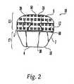
インプラント10は、一般的に、上面14と、下面16と、外面18と、を含む。上面14および下面16は、さらに、歯付部分15と平坦部分17とを含んでいるのがよい。上面14および下面16の歯付部分15は、一般的に、同じ寸法及び形状のものであるのがよく、歯付部分15は前端6に向かって形成され、平坦部分17は後端4に向かって形成されている。 The implant 10 generally includes an
インプラント10は、好ましくは、第一部品20と第二部品30の連結によって形成される。第一部品20は、好ましくは、皮質骨で形成される。第二部品30は、好ましくは、海綿質骨で構成される。第一部品20および第二部品30は、第一部品20と第二部品30が互いに並んで連結されるように、好ましくは、あり継ぎ40で連結される。第一部品20と第二部品30は、第一孔28と第一孔38(図示せず)をさらに含み、第一部品20と第二部品30があり継ぎ40に沿ってスライドするのを防止するピン50がこれらの孔に挿入されているのがよい。第一孔28は、第一部品20の全長を貫通するように形成されているのが良い。第二孔38は、第二部品30の全長を貫通するように形成されてもよいし、あるいは、その一部分に形成されていても良い。ピン50は、第一部品20と第二部品30の全体にわたって挿入されていても良く、あるいはその一部分のみを通して挿入されていても良い。ピン50は、ピンが完全に挿入されたときに、ピン50が第一孔28か第二孔38のどちらかから突出するような寸法となっているのが良い。この場合には、第一孔28または第二孔38から突出するピン50の余分の部分を、さらなる処理によって取り除くのがよい。変形例として、ピンは、第一孔28および/または第二孔38の両方を全部にわたって貫いて延びないような寸法となっていても良い。 The implant 10 is preferably formed by the connection of the
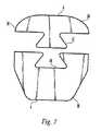
図7に示すように、あり継ぎ40の雄部分42は、第一部品20に形成され、あり継ぎ40の雌部分44は、第二部品30に形成される。しかしながら、変形実施形態では、雄部分42が第二部品30に形成され、雌部分44が第一部品20に成形されてもよい。雄部分42は、好ましくは約3mmの長さz、最も狭い箇所で好ましくは約3.1mmの第一の幅x、最も広い箇所で好ましくは約6.3mmの第二の幅yを有するのが良く、雌部分44は、対応する寸法を有している(図13参照)。変形実施形態では、雌部分44は、雄部分42の寸法よりわずかに小さい寸法を有し、かくして、雄部分42と雌部分44との間にしまり嵌めを作る。しかしながら、雄部分42および雌部分は、本発明の精神と範囲から逸脱することなく、上述の寸法と異なる寸法を有していても良いことは理解すべきである。加えて、一つ以上のあり連結および/または一つ以上のピン連結を、インプラント10を形成するのに使用してもよい。さらに、ピンを、別の位置に挿入しても良い。さらに、第一部品20および第二部品30を連結する他の方法を、本発明の精神と範囲から逸脱することなく使用しても良い。 As shown in FIG. 7, the male portion 42 of the dovetail 40 is formed on the
インプラント10は、歯付部分14,16内に形成された複数の歯12を有し、歯12は、好ましくは、インプラント10と治療されるべき椎骨の終板との間の機械的な連結を行う。好ましくは、図5および図6に示すように、歯12は、ピラミッド形状をなし、頂点から底面までに形成される角度は約60°であるのがよい。変形例として、歯12は、鋸歯が前後方向に延びる鋸歯形状を有してもよい(図12参照)。 The implant 10 has a plurality of
図1から図4に示すように、歯付部分15の大部分は、第一部品20の全上面14と全下面16とで構成される。これらの歯12は、好ましくは皮質骨で形成されるから、歯12は、自身を椎骨表面へ突き刺し、隣接した椎骨との連結を高めるのに十分な強さと堅さを有する。また、第一部品20に形成される歯12と同じ強さおよび堅さを有しないが、製造工程(さらに下記に記載する)を簡単にするために、歯12が第二部品30にも形成されるのも良い。 As shown in FIGS. 1 to 4, most of the
歯12は、一般的に、二次元の配列またはパターンに配置される。好ましい実施形態では、歯12は、等間隔の横列および縦列からなる配列に配置される。しかしながら、歯12を、本発明の精神と範囲から逸脱することなしに、歯付部分15内に多数の異なる方法で配置しても良いことは、当業者には容易に分かる。 The
平坦部分17は、好ましくは、全体的に第二部品30の上面14および下面16に構成される。海綿質骨で形成される平坦部分17は、歯付部分15よりもより延性であり、治療されるべき椎骨の表面輪郭に一致するように変形する。これは、インプラント10の表面の過剰な輪郭なしに、椎骨間のインプラント10の最適な適合をさらに保証し、椎骨とインプラント10との融合を促進する。 The flat portion 17 is preferably configured generally on the
理想的には、椎間インプラントは、新しい骨の成長の促進を最大にするように、治療されるべき椎骨間に適切な間隔を維持するのに十分な支持を提供しながら、できるだけ多くの海綿質骨を含む。皮質骨で構成されたインプラント10の第一部品20を適切に寸法決めし、且つ成形することにより、また第一部品20を、治療されるべき椎骨によってインプラント10に及ぼされる力の大部分を受けるように適切に整合させることにより、インプラント10は、必要な皮質骨の量を最小にしながら、椎骨間に適切な距離を維持するのに十分な強さを有する。そして、海綿質骨で構成されたインプラント10の残部(即ち第二部品30)を、より有利には、治療されるべき椎骨間の新しい骨の成長を促進するのに使用することができ、かくして椎骨とインプラント10に長期の安定性を提供する。インプラント10の荷重支持のほとんどが第一部品20に起こるので、第一部品20に形成された歯12が椎骨の表面に噛み込む有効性が、高められる。第一部品20、したがって歯12に加えられる力の付与は、椎骨の表面に侵入して、該表面をつかむ歯12の能力を高め、かくして、インプラント10が新しい骨の成長によって椎骨と融合するまで、インプラント10の短期の滑りを防止する。 Ideally, the intervertebral implant will provide as much sponge as possible while providing sufficient support to maintain the proper spacing between the vertebrae to be treated to maximize the promotion of new bone growth. Including bone. By appropriately sizing and shaping the
かくして、インプラント10は、椎間融合の外科的方法で同種骨の使用を改善するために、皮質骨と海綿質骨の異なる性質の利点を有する。所望の性質に応じて、皮質骨と海綿質骨の異なる組み合わせを選択してもよいから、インプラント10を、使用者の要望に応じて注文で作っても良い。本発明によるインプラント10は、また、適当な大きさのインプラントを形成するには十分に大きくない同種骨片を、インプラント10の一部を形成するのに代わりに、使用しても良いので、入手し得る材料のより効率的な使用を考慮しても良い。 Thus, the implant 10 has the advantage of different properties of cortical and cancellous bone in order to improve the use of allogenic bone in surgical methods of intervertebral fusion. Depending on the desired properties, different combinations of cortical and cancellous bone may be selected, so that the implant 10 may be custom made according to the user's desire. The implant 10 according to the present invention is also available because an allograft that is not large enough to form an appropriately sized implant may be used instead of forming part of the implant 10. More efficient use of possible materials may be considered.
図1から図4に示す好ましい実施形態では、上面14および下面16は互いに平行である。しかしながら、脊椎の或る領域では、患部のディスクを取り除いた後に脊椎の自然な湾曲を回復するために、インプラント10が傾斜面および/または曲面を有することが望ましい。例えば、図8および図9に示すように、インプラント220は、上面214および下面216がそれぞれ角度θをなす、くさび形輪郭を有していても良い。角度θは、好ましくは、約2°ないし約5°の範囲内にあり、好ましくは約3.5°である。図10および図11に示すように、さらに他の実施形態では、下面116は角度φをなし、上面114は椎骨の終板の構造の表面と一致するように湾曲させる。角度φは、好ましくは、約2°ないし約5°の範囲内にあり、好ましくは約3.5°である。上面114の曲率半径は、約8mmないし約25mmの範囲内にあり、好ましくは約14mmである。 In the preferred embodiment shown in FIGS. 1-4, the
上にした実施形態では、さらに図13に示すように、外面18は、後端4が平坦で、前端6が湾曲されるように形成される。前端6は、好ましくは約15mmないし約25mmの範囲内、好ましくは約20mmの曲率半径を有する。前端6から後端4までのインプラント10の長さLは、好ましくは、約10mmないし約15mmの範囲内にあり、好ましくは約12.5mmである。第一部品20は、好ましくは約4mmないし約8mmの範囲内の長さl(雄部分42を含む)を有し、好ましくは約6mmである。最も幅広の箇所で中間面70から側面72までのインプラント10の幅Wは、好ましくは約10mmないし約18mmの範囲内にあり、好ましくは約15mmである。さらに、歯付部分15に対応する外面18の側面5は、互いに平行であり、平坦部分17に対応する外面18の側面7は、角度αで後端4に向かって傾斜している。角度αは、好ましくは約20°ないし約40°の範囲内にあり、好ましくは約30°である。この外形では、インプラント10は、理想的には、頸椎間に使用される。しかしながら、外面18が、脊椎の異なる領域で椎骨間でのインプラント10の使用を最適にするために、多くの異なる外形をとってもよいことは、当業者にとって容易に分かる。 In the embodiment described above, as shown in FIG. 13, the
インプラント10は、まず第一部品20および第二部品30を皮質および海綿質の同種骨からおおざっぱに成形することによって製造される。次いで、あり継ぎ40の雄部分42および雌部分44を、それぞれ第一部品20および第二部品30に形成する。ピン50のための孔28および孔38を第一部品20および第二部品30に形成する。次いで、雄部分42を、雌部分44に挿入し、ピン50を孔28および孔38に挿入する。望むなら、接着剤を第一部品20と第二部品30との間に使用しても良い。好ましい実施形態では、ピン50は、ピン50の外面と孔28および孔38との間に僅かな締め代があるように寸法決めされる。かくして、ピン50は、ピン50と孔28および孔38との間のしまり嵌めによって孔28および孔38内でしっかり固定される。変形例として、ピン50を孔28および孔38内でしっかり固定するために、接着剤を使用しても良い。次いで、上面14および下面16の平坦部分17、並びに外面18を、適切な所望の形状に形成する。最後に、歯12を上面14および下面16に形成する。好ましい実施形態では、インプラント10の部品や部分の成形は、コンピュータ制御のフライス切削で行われるのが良い。しかしながら、インプラント10の様々な部品を形成する他の方法も使用できる。 The implant 10 is manufactured by first roughly molding the
上述の製造方法を使用して、歯12を、その頂点が平坦部分17の表面で定められる平面に或いは該平面より下方にあるように形成する。他の変形例の実施形態では、平坦部分17を形成する前に、先に歯12を上面14および下面16に形成することによって、歯12を、平坦部分17の平面から突出するように形成してもよい。さらに、第一部品20を第二部品30に結合する前に、歯12を第一部品20の上面14および下面16にフライス加工することによって、歯12を皮質骨のみに形成しても良い。しかしながら、これは製造工程の複雑さを増大させる。 Using the manufacturing method described above, the
患部のディスクが取り除かれた後に椎間の空間を適切な寸法に回復するために、インプラント10は、取り除かれたディスクの高さに一致する寸法の高さhを有する。椎間板切除では、典型的に、hは約5mmないし約12mmの間であるが、他の高さを使用しても良い。 In order to restore the intervertebral space to an appropriate size after the affected disc has been removed, the implant 10 has a height h that is sized to match the height of the removed disc. For discectomy, h is typically between about 5 mm and about 12 mm, although other heights may be used.
インプラント10は、また、椎体切除のために形成されても良い。このような場合には、インプラント10を、hが約10mmないし約150mmとなるように形成することができることに注目すべきである。他の高さを使用しても良い。これらのより大きい寸法は、椎体切除、即ちいくつかの椎骨部分を取り除く外科手術に使用される。インプラント10は、骨の取り除かれた部分によって作られた空間に挿入される。椎体切除の性質により、インプラントに必要な寸法を術前に正確に決定することは非常に困難である。かくして、インプラント10は、外科医によって適切な寸法に切断される。このような場合には、インプラント10は、好ましくは上面14か下面16のいずれかにのみ歯12を有する。 The implant 10 may also be formed for vertebral body resection. It should be noted that in such cases, the implant 10 can be formed such that h is from about 10 mm to about 150 mm. Other heights may be used. These larger dimensions are used for vertebral body excision, i.e. surgery to remove some vertebral parts. The implant 10 is inserted into the space created by the removed part of the bone. Due to the nature of the vertebral body excision, it is very difficult to accurately determine the required dimensions for the implant before surgery. Thus, the implant 10 is cut to the appropriate dimensions by the surgeon. In such cases, the implant 10 preferably has
椎骨間にインプラントを移植するための挿入体を受け入れるねじ孔(図示せず)を、外面18に沿って、インプラント10の前端6、側面72、または中間面70に形成しても良い。変形例として、外面18の少なくとも一部分、例えばインプラント10の前端6、並びに中間面70および側面72の一部分に沿ってきちんと合わせることによって、インプラント10を保持するために特別に構成された道具を使用しても良い。インプラント10を挿入する他の手段を、上述の方法に加えて、またはそれに代えて、用いても良い。 A screw hole (not shown) for receiving an insert for implanting the implant between the vertebrae may be formed along the
上述の実施形態は、皮質骨の単一部材と海綿質骨の単一部材で形成される部品を含んでいたが、皮質骨および/または海綿質骨の複数の部材を、本発明によるインプラントの部品を形成するのに使用しても良いことは、理解されよう。また、上述の実施形態は、互いに結合する二つの部品で形成されていたが、二つ以上の部品で形成されるインプラントも本発明の精神と範囲内である。 While the above-described embodiments included a component formed of a single member of cortical bone and a single member of cancellous bone, multiple members of cortical and / or cancellous bone may be used in the implant according to the present invention. It will be appreciated that it may be used to form a part. Moreover, although the above-mentioned embodiment was formed with the two components couple | bonded together, the implant formed with two or more components is also within the spirit and scope of the present invention.
ここに開示した本発明の説明的な実施形態は、上述の目的を達成するが、多くの修正および他の実施形態が当業者によって工夫されてもよいことは明らかである。したがって、添付の請求項は、本発明の精神と範囲内に入る、全てのそのような修正や実施形態を含むつもりであることは理解されよう。 While the illustrative embodiments of the present invention disclosed herein achieve the above-described objectives, it will be apparent that many modifications and other embodiments may be devised by those skilled in the art. Therefore, it will be understood that the appended claims are intended to cover all such modifications and embodiments that fall within the spirit and scope of the invention.
Claims (12)
Translated fromJapanese皮質骨で構成された第一部品と、
海綿質骨で構成された第二部品と、を含み、
第一部品および第二部品は、あり継ぎで連結され、
上面および下面は第一部品および第二部品の組み合わせによって形成され、
第一部品の実質的に全上面および下面は、さらに複数の歯を有する、
ことを特徴とする椎間インプラント。An intervertebral implant having an upper surface and a lower surface,
A first part composed of cortical bone,
A second part composed of cancellous bone,
The first part and the second part are connected by a dovetail,
The upper and lower surfaces are formed by a combination of the first part and the second part,
Substantially the entire top and bottom surfaces of the first component further have a plurality of teeth;
An intervertebral implant characterized by that.
ことを特徴とする請求項1に記載のインプラント。The teeth are arranged in a two-dimensional array, the teeth are pyramid shaped,
The implant according to claim 1.
ことを特徴とする請求項1に記載のインプラント。The implant has a wedge-shaped profile that helps restore the disc height and spine curvature,
The implant according to claim 1.
ことを特徴とする請求項2に記載のインプラント。Has a front height greater than the rear height to create a wedge-shaped profile,
The implant according to claim 2.
ことを特徴とする請求項1に記載のインプラント。The top and bottom surfaces are parallel and are spaced a distance close to the disc space,
The implant according to claim 1.
ことを特徴とする請求項1に記載のインプラント。The top surface is a curved surface that is contoured to mimic the endplate of an adjacent vertebra,
The implant according to claim 1.
ことを特徴とする請求項1に記載のインプラント。Further comprising an outer surface formed by a combination of the first part and the second part, the outer surface being processed into a predetermined shape;
The implant according to claim 1.
ことを特徴とする請求項1に記載のインプラント。The implant further includes a pin, the pin connecting the first part and the second part;
The implant according to claim 1.
ことを特徴とする請求項1に記載のインプラント。The first part and the second part are connected by an adhesive,
The implant according to claim 1.
皮質骨で第一部品を形成する工程と、
海綿質骨で第二部品を形成する工程と、
第一部品および第二部品を、あり継ぎを用いて連結する工程と、
上面および下面に複数の歯を形成する工程と、を含む、
ことを特徴とする椎間インプラントの製造方法。A method of manufacturing an intervertebral implant having an upper surface, a lower surface, and an outer surface,
Forming a first part with cortical bone;
Forming a second part with cancellous bone;
Connecting the first part and the second part using a dovetail;
Forming a plurality of teeth on the upper surface and the lower surface,
A method of manufacturing an intervertebral implant characterized by the above.
ことを特徴とする請求項10に記載の方法。Forming the first part further includes forming a male part of the dovetail, and forming the first part further includes forming a female part of the dovetail;
The method according to claim 10.
ピンを形成する工程と、
第一部品を第二部品に連結した後、ピンを雄部分と雌部分の孔に挿入する工程と、をさらに含む、
ことを特徴とする請求項11に記載の方法。Forming the first part further includes forming a hole in the male part, and forming the second part further includes forming a hole in the second part;
Forming a pin;
After connecting the first part to the second part, inserting the pins into the holes of the male and female parts;
The method according to claim 11.
Applications Claiming Priority (2)
| Application Number | Priority Date | Filing Date | Title |
|---|---|---|---|
| US49992603P | 2003-09-02 | 2003-09-02 | |
| PCT/US2004/028544WO2005020861A1 (en) | 2003-09-02 | 2004-09-02 | Multipiece allograft implant |
Publications (2)
| Publication Number | Publication Date |
|---|---|
| JP2007503924Atrue JP2007503924A (en) | 2007-03-01 |
| JP2007503924A5 JP2007503924A5 (en) | 2008-05-15 |
Family
ID=34272888
Family Applications (1)
| Application Number | Title | Priority Date | Filing Date |
|---|---|---|---|
| JP2006525432APendingJP2007503924A (en) | 2003-09-02 | 2004-09-02 | Multiple allograft implants |
Country Status (11)
| Country | Link |
|---|---|
| US (2) | US7226482B2 (en) |
| EP (1) | EP1670396A4 (en) |
| JP (1) | JP2007503924A (en) |
| KR (1) | KR101106427B1 (en) |
| CN (1) | CN1901853B (en) |
| AU (1) | AU2004268673B8 (en) |
| BR (1) | BRPI0414078A (en) |
| CA (1) | CA2537122C (en) |
| NZ (1) | NZ546053A (en) |
| WO (1) | WO2005020861A1 (en) |
| ZA (1) | ZA200602137B (en) |
Cited By (1)
| Publication number | Priority date | Publication date | Assignee | Title |
|---|---|---|---|---|
| JP2010537729A (en)* | 2007-08-27 | 2010-12-09 | ウォーソー・オーソペディック・インコーポレーテッド | Spinal interbody replacement device |
Families Citing this family (129)
| Publication number | Priority date | Publication date | Assignee | Title |
|---|---|---|---|---|
| AR027685A1 (en)* | 2000-03-22 | 2003-04-09 | Synthes Ag | METHOD AND METHOD FOR CARRYING OUT |
| AR038680A1 (en) | 2002-02-19 | 2005-01-26 | Synthes Ag | INTERVERTEBRAL IMPLANT |
| CA2515247C (en) | 2003-02-06 | 2010-10-05 | Synthes (U.S.A.) | Intervertebral implant |
| AU2004212942A1 (en) | 2003-02-14 | 2004-09-02 | Depuy Spine, Inc. | In-situ formed intervertebral fusion device |
| US20170020683A1 (en)* | 2003-04-21 | 2017-01-26 | Rsb Spine Llc | Bone plate stabilization system and method for its use |
| US7067123B2 (en) | 2003-04-29 | 2006-06-27 | Musculoskeletal Transplant Foundation | Glue for cartilage repair |
| US7901457B2 (en) | 2003-05-16 | 2011-03-08 | Musculoskeletal Transplant Foundation | Cartilage allograft plug |
| NZ550331A (en)* | 2004-03-26 | 2009-09-25 | Synthes Usa | Allograft implant |
| US7837740B2 (en) | 2007-01-24 | 2010-11-23 | Musculoskeletal Transplant Foundation | Two piece cancellous construct for cartilage repair |
| US20070276493A1 (en)* | 2005-02-17 | 2007-11-29 | Malandain Hugues F | Percutaneous spinal implants and methods |
| EP1868539A2 (en) | 2005-04-15 | 2007-12-26 | Musculoskeletal Transplant Foundation | Vertebral disc repair |
| US7815926B2 (en) | 2005-07-11 | 2010-10-19 | Musculoskeletal Transplant Foundation | Implant for articular cartilage repair |
| US8366773B2 (en) | 2005-08-16 | 2013-02-05 | Benvenue Medical, Inc. | Apparatus and method for treating bone |
| WO2008103781A2 (en) | 2007-02-21 | 2008-08-28 | Benvenue Medical, Inc. | Devices for treating the spine |
| AU2006279558B2 (en) | 2005-08-16 | 2012-05-17 | Izi Medical Products, Llc | Spinal tissue distraction devices |
| AU2006292224B2 (en) | 2005-09-19 | 2013-08-01 | Histogenics Corporation | Cell-support matrix and a method for preparation thereof |
| USH2261H1 (en)* | 2005-09-26 | 2011-08-02 | Simmons Jr James W | Disc and facet replacement |
| WO2007044229A2 (en)* | 2005-09-28 | 2007-04-19 | Calcitec, Inc. | Surface treatments for calcium phosphate-based implants |
| WO2007090784A1 (en)* | 2006-02-03 | 2007-08-16 | Zimmer Gmbh | Tibia platform implant |
| EP1988855A2 (en) | 2006-02-27 | 2008-11-12 | Synthes GmbH | Intervertebral implant with fixation geometry |
| US8282641B2 (en)* | 2006-03-28 | 2012-10-09 | Depuy Spine, Inc. | Methods and instrumentation for disc replacement |
| US8137404B2 (en)* | 2006-03-28 | 2012-03-20 | Depuy Spine, Inc. | Artificial disc replacement using posterior approach |
| US20070233244A1 (en)* | 2006-03-28 | 2007-10-04 | Depuy Spine, Inc. | Artificial Disc Replacement Using Posterior Approach |
| CA2658934A1 (en) | 2006-07-25 | 2008-01-31 | Musculoskeletal Transplant Foundation | Packed demineralized cancellous tissue forms for disc nucleus augmentation, restoration, or replacement and methods of implantation |
| US20080058940A1 (en)* | 2006-08-22 | 2008-03-06 | Shing Sheng Wu | Artificial intervertebral disc |
| US9943410B2 (en) | 2011-02-28 | 2018-04-17 | DePuy Synthes Products, Inc. | Modular tissue scaffolds |
| US12171904B2 (en) | 2006-10-30 | 2024-12-24 | Trs Holdings Llc | Mineral coated scaffolds |
| US20080125863A1 (en)* | 2006-11-28 | 2008-05-29 | Mckay William F | Implant designs and methods of improving cartilage repair |
| WO2008070863A2 (en) | 2006-12-07 | 2008-06-12 | Interventional Spine, Inc. | Intervertebral implant |
| US9039768B2 (en) | 2006-12-22 | 2015-05-26 | Medos International Sarl | Composite vertebral spacers and instrument |
| US20080234822A1 (en)* | 2007-01-26 | 2008-09-25 | Tutogen Medical, U.S., Inc. | Method and Apparatus for Stabilization and Fusion of Adjacent Bone Segments |
| EP2124778B1 (en) | 2007-02-21 | 2019-09-25 | Benvenue Medical, Inc. | Devices for treating the spine |
| US8435551B2 (en) | 2007-03-06 | 2013-05-07 | Musculoskeletal Transplant Foundation | Cancellous construct with support ring for repair of osteochondral defects |
| US8900307B2 (en) | 2007-06-26 | 2014-12-02 | DePuy Synthes Products, LLC | Highly lordosed fusion cage |
| CA2688437C (en) | 2007-06-29 | 2015-12-22 | Synthes Usa, Llc | Flexible chain implants and instrumentation |
| US20100198354A1 (en) | 2007-08-01 | 2010-08-05 | Jeffrey Halbrecht | Method and system for patella tendon realignment |
| US8685099B2 (en)* | 2007-08-14 | 2014-04-01 | Warsaw Orthopedic, Inc. | Multiple component osteoimplant |
| FR2923156B1 (en)* | 2007-11-05 | 2010-08-13 | Medicrea International | INTERVERTEBRAL IMPLANT FOR IMMOBILIZING A VERTEBRA IN RELATION TO ANOTHER |
| JP2011502708A (en)* | 2007-11-16 | 2011-01-27 | ジンテス ゲゼルシャフト ミット ベシュレンクテル ハフツング | Low profile intervertebral implant |
| US7967866B2 (en)* | 2007-11-27 | 2011-06-28 | Warsaw Orthopedic, Inc. | Stackable intervertebral devices and methods of use |
| US8747473B2 (en)* | 2007-11-30 | 2014-06-10 | Custom Spine, Inc. | Modular lateral expansion device |
| US7985231B2 (en) | 2007-12-31 | 2011-07-26 | Kyphon Sarl | Bone fusion device and methods |
| US7799056B2 (en) | 2007-12-31 | 2010-09-21 | Warsaw Orthopedic, Inc. | Bone fusion device and methods |
| EP2237748B1 (en) | 2008-01-17 | 2012-09-05 | Synthes GmbH | An expandable intervertebral implant |
| EP2265220A1 (en) | 2008-03-05 | 2010-12-29 | Musculoskeletal Transplant Foundation | Cancellous constructs, cartilage particles and combinations of cancellous constructs and cartilage particles |
| US8795365B2 (en)* | 2008-03-24 | 2014-08-05 | Warsaw Orthopedic, Inc | Expandable devices for emplacement in body parts and methods associated therewith |
| US20090248092A1 (en) | 2008-03-26 | 2009-10-01 | Jonathan Bellas | Posterior Intervertebral Disc Inserter and Expansion Techniques |
| US8936641B2 (en) | 2008-04-05 | 2015-01-20 | DePuy Synthes Products, LLC | Expandable intervertebral implant |
| CN102256570B (en) | 2008-11-07 | 2015-09-02 | 斯恩蒂斯有限公司 | Spacer and connecting plate assembly between vertebral bodies |
| WO2010096773A1 (en)* | 2009-02-20 | 2010-08-26 | Spartan Cage Holding, Llc | Interbody fusion system with intervertebral implant retention assembly |
| US8535327B2 (en) | 2009-03-17 | 2013-09-17 | Benvenue Medical, Inc. | Delivery apparatus for use with implantable medical devices |
| US9526620B2 (en) | 2009-03-30 | 2016-12-27 | DePuy Synthes Products, Inc. | Zero profile spinal fusion cage |
| US10842642B2 (en)* | 2009-04-16 | 2020-11-24 | Nuvasive, Inc. | Methods and apparatus of performing spine surgery |
| US20110015743A1 (en)* | 2009-07-14 | 2011-01-20 | Doctors Research Group, Inc. | Multi-density polymeric interbody spacer |
| US20110012280A1 (en)* | 2009-07-14 | 2011-01-20 | Doctors Research Group, Inc. | Method for fabricating a multi-density polymeric interbody spacer |
| US10349980B2 (en) | 2009-08-27 | 2019-07-16 | The Foundry, Llc | Method and apparatus for altering biomechanics of the shoulder |
| US9668868B2 (en) | 2009-08-27 | 2017-06-06 | Cotera, Inc. | Apparatus and methods for treatment of patellofemoral conditions |
| CA2771332C (en) | 2009-08-27 | 2020-11-10 | Cotera, Inc. | Method and apparatus for force redistribution in articular joints |
| US9278004B2 (en) | 2009-08-27 | 2016-03-08 | Cotera, Inc. | Method and apparatus for altering biomechanics of the articular joints |
| US9861408B2 (en) | 2009-08-27 | 2018-01-09 | The Foundry, Llc | Method and apparatus for treating canine cruciate ligament disease |
| US9028553B2 (en) | 2009-11-05 | 2015-05-12 | DePuy Synthes Products, Inc. | Self-pivoting spinal implant and associated instrumentation |
| USD631966S1 (en)* | 2009-11-10 | 2011-02-01 | Globus Medical, Inc. | Basilar invagination implant |
| US8740983B1 (en) | 2009-11-11 | 2014-06-03 | Nuvasive, Inc. | Spinal fusion implants and related methods |
| US8840668B1 (en) | 2009-11-11 | 2014-09-23 | Nuvasive, Inc. | Spinal implants, instruments and related methods |
| US9393129B2 (en) | 2009-12-10 | 2016-07-19 | DePuy Synthes Products, Inc. | Bellows-like expandable interbody fusion cage |
| US20110218627A1 (en)* | 2010-03-03 | 2011-09-08 | Warsaw Orthopedic, Inc. | System and method for replacing at least a portion of a vertebral body |
| US8979860B2 (en) | 2010-06-24 | 2015-03-17 | DePuy Synthes Products. LLC | Enhanced cage insertion device |
| US9907560B2 (en) | 2010-06-24 | 2018-03-06 | DePuy Synthes Products, Inc. | Flexible vertebral body shavers |
| US8623091B2 (en) | 2010-06-29 | 2014-01-07 | DePuy Synthes Products, LLC | Distractible intervertebral implant |
| US11529241B2 (en) | 2010-09-23 | 2022-12-20 | DePuy Synthes Products, Inc. | Fusion cage with in-line single piece fixation |
| US20120078373A1 (en)* | 2010-09-23 | 2012-03-29 | Thomas Gamache | Stand alone intervertebral fusion device |
| US20120078372A1 (en) | 2010-09-23 | 2012-03-29 | Thomas Gamache | Novel implant inserter having a laterally-extending dovetail engagement feature |
| US9402732B2 (en) | 2010-10-11 | 2016-08-02 | DePuy Synthes Products, Inc. | Expandable interspinous process spacer implant |
| US9241809B2 (en) | 2010-12-21 | 2016-01-26 | DePuy Synthes Products, Inc. | Intervertebral implants, systems, and methods of use |
| WO2012088238A2 (en) | 2010-12-21 | 2012-06-28 | Synthes Usa, Llc | Intervertebral implants, systems, and methods of use |
| US9358122B2 (en) | 2011-01-07 | 2016-06-07 | K2M, Inc. | Interbody spacer |
| DE102011000375B4 (en)* | 2011-01-27 | 2022-07-14 | Aesculap Ag | Vertebral cage as a fracture implant |
| EP3485851B1 (en) | 2011-03-22 | 2021-08-25 | DePuy Synthes Products, LLC | Universal trial for lateral cages |
| US8814873B2 (en) | 2011-06-24 | 2014-08-26 | Benvenue Medical, Inc. | Devices and methods for treating bone tissue |
| US9724132B2 (en) | 2011-08-31 | 2017-08-08 | DePuy Synthes Products, Inc. | Devices and methods for cervical lateral fixation |
| US9539109B2 (en) | 2011-09-16 | 2017-01-10 | Globus Medical, Inc. | Low profile plate |
| US9204975B2 (en) | 2011-09-16 | 2015-12-08 | Globus Medical, Inc. | Multi-piece intervertebral implants |
| US9248028B2 (en) | 2011-09-16 | 2016-02-02 | DePuy Synthes Products, Inc. | Removable, bone-securing cover plate for intervertebral fusion cage |
| US10245155B2 (en) | 2011-09-16 | 2019-04-02 | Globus Medical, Inc. | Low profile plate |
| US9237957B2 (en)* | 2011-09-16 | 2016-01-19 | Globus Medical, Inc. | Low profile plate |
| US9848994B2 (en)* | 2011-09-16 | 2017-12-26 | Globus Medical, Inc. | Low profile plate |
| US10881526B2 (en) | 2011-09-16 | 2021-01-05 | Globus Medical, Inc. | Low profile plate |
| US9149365B2 (en) | 2013-03-05 | 2015-10-06 | Globus Medical, Inc. | Low profile plate |
| US9681959B2 (en) | 2011-09-16 | 2017-06-20 | Globus Medical, Inc. | Low profile plate |
| US9770340B2 (en) | 2011-09-16 | 2017-09-26 | Globus Medical, Inc. | Multi-piece intervertebral implants |
| US9398960B2 (en) | 2011-09-16 | 2016-07-26 | Globus Medical, Inc. | Multi-piece intervertebral implants |
| US8961606B2 (en) | 2011-09-16 | 2015-02-24 | Globus Medical, Inc. | Multi-piece intervertebral implants |
| US9468536B1 (en) | 2011-11-02 | 2016-10-18 | Nuvasive, Inc. | Spinal fusion implants and related methods |
| US9226764B2 (en) | 2012-03-06 | 2016-01-05 | DePuy Synthes Products, Inc. | Conformable soft tissue removal instruments |
| US9271836B2 (en) | 2012-03-06 | 2016-03-01 | DePuy Synthes Products, Inc. | Nubbed plate |
| US9468466B1 (en) | 2012-08-24 | 2016-10-18 | Cotera, Inc. | Method and apparatus for altering biomechanics of the spine |
| US10182921B2 (en) | 2012-11-09 | 2019-01-22 | DePuy Synthes Products, Inc. | Interbody device with opening to allow packing graft and other biologics |
| USD731061S1 (en) | 2012-11-28 | 2015-06-02 | Nuvasive, Inc. | Intervertebral implant |
| US10022245B2 (en) | 2012-12-17 | 2018-07-17 | DePuy Synthes Products, Inc. | Polyaxial articulating instrument |
| US9717601B2 (en) | 2013-02-28 | 2017-08-01 | DePuy Synthes Products, Inc. | Expandable intervertebral implant, system, kit and method |
| US9522070B2 (en) | 2013-03-07 | 2016-12-20 | Interventional Spine, Inc. | Intervertebral implant |
| US10085783B2 (en) | 2013-03-14 | 2018-10-02 | Izi Medical Products, Llc | Devices and methods for treating bone tissue |
| USD745159S1 (en) | 2013-10-10 | 2015-12-08 | Nuvasive, Inc. | Intervertebral implant |
| US10426630B2 (en) | 2014-02-12 | 2019-10-01 | K2M, Inc. | Spinal implant |
| US9867718B2 (en)* | 2014-10-22 | 2018-01-16 | DePuy Synthes Products, Inc. | Intervertebral implants, systems, and methods of use |
| USD858769S1 (en) | 2014-11-20 | 2019-09-03 | Nuvasive, Inc. | Intervertebral implant |
| US10077420B2 (en) | 2014-12-02 | 2018-09-18 | Histogenics Corporation | Cell and tissue culture container |
| US11426290B2 (en) | 2015-03-06 | 2022-08-30 | DePuy Synthes Products, Inc. | Expandable intervertebral implant, system, kit and method |
| EP3474784A2 (en) | 2016-06-28 | 2019-05-01 | Eit Emerging Implant Technologies GmbH | Expandable and angularly adjustable intervertebral cages with articulating joint |
| US11510788B2 (en) | 2016-06-28 | 2022-11-29 | Eit Emerging Implant Technologies Gmbh | Expandable, angularly adjustable intervertebral cages |
| US10888433B2 (en) | 2016-12-14 | 2021-01-12 | DePuy Synthes Products, Inc. | Intervertebral implant inserter and related methods |
| US11452608B2 (en) | 2017-04-05 | 2022-09-27 | Globus Medical, Inc. | Decoupled spacer and plate and method of installing the same |
| US10376385B2 (en) | 2017-04-05 | 2019-08-13 | Globus Medical, Inc. | Decoupled spacer and plate and method of installing the same |
| EP3614965A4 (en)* | 2017-04-26 | 2021-01-06 | The Regents of The University of Michigan | EAR TISSUE IMPLANT FOR EAR TISSUE CONSTRUCTION |
| US10398563B2 (en) | 2017-05-08 | 2019-09-03 | Medos International Sarl | Expandable cage |
| US11344424B2 (en) | 2017-06-14 | 2022-05-31 | Medos International Sarl | Expandable intervertebral implant and related methods |
| US10940016B2 (en) | 2017-07-05 | 2021-03-09 | Medos International Sarl | Expandable intervertebral fusion cage |
| US10966843B2 (en) | 2017-07-18 | 2021-04-06 | DePuy Synthes Products, Inc. | Implant inserters and related methods |
| US11045331B2 (en) | 2017-08-14 | 2021-06-29 | DePuy Synthes Products, Inc. | Intervertebral implant inserters and related methods |
| CN108125736A (en)* | 2018-02-09 | 2018-06-08 | 申才良 | A kind of spliced homogeneous allogenic bone fusion device |
| US11458012B2 (en) | 2018-06-07 | 2022-10-04 | The Regents Of The University Of Michigan | Scaffold for nasal tissue engineering |
| CN108742954A (en)* | 2018-06-28 | 2018-11-06 | 何清义 | A kind of plate XLIF Invasive lumbar fusion devices |
| US11446156B2 (en) | 2018-10-25 | 2022-09-20 | Medos International Sarl | Expandable intervertebral implant, inserter instrument, and related methods |
| US11896476B2 (en) | 2020-01-02 | 2024-02-13 | Zkr Orthopedics, Inc. | Patella tendon realignment implant with changeable shape |
| US11426286B2 (en) | 2020-03-06 | 2022-08-30 | Eit Emerging Implant Technologies Gmbh | Expandable intervertebral implant |
| WO2021231253A1 (en) | 2020-05-11 | 2021-11-18 | Zkr Orthopedics, Inc. | Adjustable patellar tendon realignment implant |
| US11850160B2 (en) | 2021-03-26 | 2023-12-26 | Medos International Sarl | Expandable lordotic intervertebral fusion cage |
| US11752009B2 (en) | 2021-04-06 | 2023-09-12 | Medos International Sarl | Expandable intervertebral fusion cage |
| US12090064B2 (en) | 2022-03-01 | 2024-09-17 | Medos International Sarl | Stabilization members for expandable intervertebral implants, and related systems and methods |
Citations (3)
| Publication number | Priority date | Publication date | Assignee | Title |
|---|---|---|---|---|
| US6200347B1 (en)* | 1999-01-05 | 2001-03-13 | Lifenet | Composite bone graft, method of making and using same |
| US20020029084A1 (en)* | 1998-08-03 | 2002-03-07 | Paul David C. | Bone implants with central chambers |
| WO2002065956A1 (en)* | 2001-01-22 | 2002-08-29 | Sdgi Holdings, Inc. | Modular interbody fusion implant |
Family Cites Families (133)
| Publication number | Priority date | Publication date | Assignee | Title |
|---|---|---|---|---|
| US2621145A (en) | 1949-08-17 | 1952-12-09 | Machteld E Sano | Bone mat compositions |
| CH612341A5 (en) | 1976-03-16 | 1979-07-31 | Max Bernhard Ulrich | |
| US4512038A (en) | 1979-04-27 | 1985-04-23 | University Of Medicine And Dentistry Of New Jersey | Bio-absorbable composite tissue scaffold |
| DE3042003A1 (en) | 1980-10-10 | 1982-07-15 | Hans Dr. 5609 Hückeswagen Reimer | Bone cement reinforcing component - comprises thread structure compatible with body tissue forming soft sponge |
| US4501269A (en) | 1981-12-11 | 1985-02-26 | Washington State University Research Foundation, Inc. | Process for fusing bone joints |
| GB2148122B (en) | 1983-09-30 | 1986-10-22 | Gendler El | Process for stimulating induction of bone formation and stimulation of bone regeneration by artificially perforated bone matrix |
| US5053049A (en) | 1985-05-29 | 1991-10-01 | Baxter International | Flexible prostheses of predetermined shapes and process for making same |
| US4627853A (en) | 1985-05-29 | 1986-12-09 | American Hospital Supply Corporation | Method of producing prostheses for replacement of articular cartilage and prostheses so produced |
| US4678470A (en) | 1985-05-29 | 1987-07-07 | American Hospital Supply Corporation | Bone-grafting material |
| US4717115A (en) | 1986-10-14 | 1988-01-05 | The United States Of America As Represented By The Secretary Of The Army | Adjustable mold for fabricating bone replacements |
| FI80605C (en) | 1986-11-03 | 1990-07-10 | Biocon Oy | BENKIRURGISK BIOKOMPOSITMATERIAL. |
| SU1465040A1 (en) | 1987-02-27 | 1989-03-15 | Ленинградский санитарно-гигиенический медицинский институт | Method of closing defects in case of osteomyelitis of tubular bones |
| FI78232C (en) | 1987-06-15 | 1989-07-10 | Trident Oy | IMPLANTS, SOM ERSAETTER EN TAND ELLER EN DEL AV BENVAEVNADEN MED SYNTETISKT MATERIAL. |
| US4950296A (en) | 1988-04-07 | 1990-08-21 | Mcintyre Jonathan L | Bone grafting units |
| US4858603A (en) | 1988-06-06 | 1989-08-22 | Johnson & Johnson Orthopaedics, Inc. | Bone pin |
| US4951740A (en)* | 1988-06-27 | 1990-08-28 | Texas A & M University System | Bellows heat pipe for thermal control of electronic components |
| US5609635A (en) | 1988-06-28 | 1997-03-11 | Michelson; Gary K. | Lordotic interbody spinal fusion implants |
| CA1333209C (en) | 1988-06-28 | 1994-11-29 | Gary Karlin Michelson | Artificial spinal fusion implants |
| US4936851A (en) | 1988-08-26 | 1990-06-26 | Colin Electronics Co., Ltd. | Analytic bone implant |
| US4961740B1 (en) | 1988-10-17 | 1997-01-14 | Surgical Dynamics Inc | V-thread fusion cage and method of fusing a bone joint |
| US5281226A (en) | 1989-03-31 | 1994-01-25 | Davydov Anatoly B | Missing portion of a tubular bone |
| US4994084A (en) | 1989-06-23 | 1991-02-19 | Brennan H George | Reconstructive surgery method and implant |
| US5458638A (en) | 1989-07-06 | 1995-10-17 | Spine-Tech, Inc. | Non-threaded spinal implant |
| US5290558A (en) | 1989-09-21 | 1994-03-01 | Osteotech, Inc. | Flowable demineralized bone powder composition and its use in bone repair |
| DE3933459A1 (en) | 1989-10-06 | 1991-04-18 | Karsten Dipl Ing Reumann | Biomedical implant production equipment - uses computer tomographic image to generate implant profile for component mfr. |
| US5112354A (en) | 1989-11-16 | 1992-05-12 | Northwestern University | Bone allograft material and method |
| US5062850A (en) | 1990-01-16 | 1991-11-05 | University Of Florida | Axially-fixed vertebral body prosthesis and method of fixation |
| AT394307B (en) | 1990-07-24 | 1992-03-10 | Mohamed Ibrahim Dr Rasheed | SPINE PROSTHESIS |
| EP0475077B1 (en) | 1990-09-10 | 1996-06-12 | Synthes AG, Chur | Bone regeneration membrane |
| ES2076467T3 (en) | 1990-10-31 | 1995-11-01 | El Gendler | FLEXIBLE MEMBRANES PRODUCED WITH ORGANIC BONE MATTER FOR THE REPAIR AND RECONSTRUCTION OF PARTS OF THE SKELETON. |
| US5348788A (en) | 1991-01-30 | 1994-09-20 | Interpore Orthopaedics, Inc. | Mesh sheet with microscopic projections and holes |
| US5192327A (en) | 1991-03-22 | 1993-03-09 | Brantigan John W | Surgical prosthetic implant for vertebrae |
| JP3007903B2 (en) | 1991-03-29 | 2000-02-14 | 京セラ株式会社 | Artificial disc |
| DE4215137A1 (en) | 1991-06-04 | 1992-12-10 | Man Ceramics Gmbh | IMPLANT FOR SPINE PILLARS |
| US5211664A (en) | 1992-01-14 | 1993-05-18 | Forschungsinstitut, Davos Laboratorium Fur Experimentelle Chirugie | Shell structure for bone replacement |
| US5314476A (en) | 1992-02-04 | 1994-05-24 | Osteotech, Inc. | Demineralized bone particles and flowable osteogenic composition containing same |
| AU667877B2 (en) | 1992-02-14 | 1996-04-18 | Board Of Regents, The University Of Texas System | Multi-phase bioerodible implant/carrier and method of manufacturing and using same |
| US5876452A (en) | 1992-02-14 | 1999-03-02 | Board Of Regents, University Of Texas System | Biodegradable implant |
| US6013853A (en) | 1992-02-14 | 2000-01-11 | The University Of Texas System | Continuous release polymeric implant carrier |
| US5366507A (en) | 1992-03-06 | 1994-11-22 | Sottosanti John S | Method for use in bone tissue regeneration |
| DE4220218C2 (en) | 1992-06-20 | 1994-09-22 | S & G Implants Gmbh | Implant with an open-cell or open-pore metal structure |
| FR2697996B1 (en) | 1992-11-17 | 1995-01-06 | Medinov Sa | Modular set for hip prosthesis. |
| DE4242889A1 (en) | 1992-12-18 | 1994-06-23 | Merck Patent Gmbh | Hollow endoprostheses with filling that promotes bone growth |
| FR2700947B1 (en) | 1993-02-03 | 1995-03-17 | Daniel Noyer | Prosthetic femoral implant for dysplastic hip. |
| EP0610837B1 (en) | 1993-02-09 | 2001-09-05 | Acromed Corporation | Spine disc |
| US5405391A (en) | 1993-02-16 | 1995-04-11 | Hednerson; Fraser C. | Fusion stabilization chamber |
| DE4323034C1 (en) | 1993-07-09 | 1994-07-28 | Lutz Biedermann | Placeholders, especially for an intervertebral disc |
| US5423817A (en) | 1993-07-29 | 1995-06-13 | Lin; Chih-I | Intervertebral fusing device |
| FR2708461B1 (en) | 1993-08-06 | 1995-09-29 | Advanced Technical Fabrication | Interbody implant for spine. |
| DE4328062A1 (en) | 1993-08-20 | 1995-02-23 | Heinrich Ulrich | Implant to replace vertebral bodies and / or to stabilize and fix the spine |
| BE1007549A3 (en) | 1993-09-21 | 1995-08-01 | Beckers Louis Francois Charles | Implant. |
| US5514180A (en) | 1994-01-14 | 1996-05-07 | Heggeness; Michael H. | Prosthetic intervertebral devices |
| FR2715293B1 (en) | 1994-01-26 | 1996-03-22 | Biomat | Vertebral interbody fusion cage. |
| DE4403509A1 (en) | 1994-02-04 | 1995-08-10 | Draenert Klaus | Material and process for its manufacture |
| DE4409392A1 (en) | 1994-03-18 | 1995-09-21 | Biedermann Motech Gmbh | Adjustable vertebral body |
| US5571189A (en) | 1994-05-20 | 1996-11-05 | Kuslich; Stephen D. | Expandable fabric implant for stabilizing the spinal motion segment |
| JP3509103B2 (en) | 1994-05-23 | 2004-03-22 | スルザー スパイン−テック インコーポレイテッド | Intervertebral fusion implant |
| US5906827A (en) | 1994-06-03 | 1999-05-25 | Creative Biomolecules, Inc. | Matrix for the manufacture of autogenous replacement body parts |
| US5507818A (en) | 1994-06-30 | 1996-04-16 | Mclaughlin; John A. | Multipolar joint endoprosthesis |
| DE4423257C2 (en) | 1994-07-02 | 2001-07-12 | Ulrich Heinrich | Implant to be inserted between the vertebral body of the spine as a placeholder |
| US5792327A (en)* | 1994-07-19 | 1998-08-11 | Corning Incorporated | Adhering metal to glass |
| US5980522A (en) | 1994-07-22 | 1999-11-09 | Koros; Tibor | Expandable spinal implants |
| US5885299A (en) | 1994-09-15 | 1999-03-23 | Surgical Dynamics, Inc. | Apparatus and method for implant insertion |
| US6033405A (en) | 1994-09-15 | 2000-03-07 | Surgical Dynamics, Inc. | Apparatus and method for implant insertion |
| TW316844B (en) | 1994-12-09 | 1997-10-01 | Sofamor Danek Group Inc | |
| ES2259169T3 (en) | 1994-12-09 | 2006-09-16 | Sdgi Holdings, Inc. | REPLACEMENT OF ADJUSTABLE VERTEBRAL BODY. |
| DE19504867C1 (en) | 1995-02-14 | 1996-02-29 | Harms Juergen | Position retainer for spine |
| CN1134810A (en) | 1995-02-17 | 1996-11-06 | 索发默达纳集团股份有限公司 | Improved interbody spinal fusion implants |
| US5782919A (en) | 1995-03-27 | 1998-07-21 | Sdgi Holdings, Inc. | Interbody fusion device and method for restoration of normal spinal anatomy |
| US5735905A (en) | 1995-04-27 | 1998-04-07 | Southwest Research Institute | Shock absorbing element for a load bearing prosthesis |
| US5702449A (en) | 1995-06-07 | 1997-12-30 | Danek Medical, Inc. | Reinforced porous spinal implants |
| WO1996039988A2 (en) | 1995-06-07 | 1996-12-19 | Michelson Gary K | Translateral spinal implant |
| US5865849A (en) | 1995-06-07 | 1999-02-02 | Crosscart, Inc. | Meniscal heterografts |
| US6039762A (en) | 1995-06-07 | 2000-03-21 | Sdgi Holdings, Inc. | Reinforced bone graft substitutes |
| US5782915A (en) | 1995-09-15 | 1998-07-21 | Stone; Kevin R. | Articular cartilage heterografts |
| US5944755A (en) | 1995-09-15 | 1999-08-31 | Crosscart, Inc. | Articular cartilage xenografts |
| US5902338A (en) | 1995-09-15 | 1999-05-11 | Crosscart, Inc. | Anterior cruciate ligament heterograft |
| US5683394A (en) | 1995-09-29 | 1997-11-04 | Advanced Spine Fixation Systems, Inc. | Fusion mass constrainer |
| US5888222A (en) | 1995-10-16 | 1999-03-30 | Sdgi Holding, Inc. | Intervertebral spacers |
| US5989289A (en) | 1995-10-16 | 1999-11-23 | Sdgi Holdings, Inc. | Bone grafts |
| KR100415064B1 (en) | 1995-10-20 | 2005-04-06 | 신테스 아게 츄어 | Intervertebral implant |
| JP3592416B2 (en)* | 1995-10-31 | 2004-11-24 | 晃敏 吉田 | Measuring device for intraocular substances |
| CA2242645A1 (en) | 1995-12-08 | 1997-06-12 | Robert S. Bray, Jr. | Anterior stabilization device |
| US5766253A (en) | 1996-01-16 | 1998-06-16 | Surgical Dynamics, Inc. | Spinal fusion device |
| US5814084A (en) | 1996-01-16 | 1998-09-29 | University Of Florida Tissue Bank, Inc. | Diaphysial cortical dowel |
| ES2260783T3 (en) | 1996-01-17 | 2006-11-01 | Osteotech, Inc. | PROCEDURE TO PRODUCE FLEXIBLE SHEETS FROM LONG AND DEMINERALIZED OSE PARTICLES. |
| US5824078A (en) | 1996-03-11 | 1998-10-20 | The Board Of Trustees Of The University Of Arkansas | Composite allograft, press, and methods |
| US5702455A (en) | 1996-07-03 | 1997-12-30 | Saggar; Rahul | Expandable prosthesis for spinal fusion |
| US5895426A (en) | 1996-09-06 | 1999-04-20 | Osteotech, Inc. | Fusion implant device and method of use |
| FR2753368B1 (en) | 1996-09-13 | 1999-01-08 | Chauvin Jean Luc | EXPANSIONAL OSTEOSYNTHESIS CAGE |
| US5968098A (en) | 1996-10-22 | 1999-10-19 | Surgical Dynamics, Inc. | Apparatus for fusing adjacent bone structures |
| WO1998017209A2 (en) | 1996-10-23 | 1998-04-30 | Sdgi Holdings, Inc. | Spinal spacer |
| US5728159A (en) | 1997-01-02 | 1998-03-17 | Musculoskeletal Transplant Foundation | Serrated bone graft |
| US5749916A (en) | 1997-01-21 | 1998-05-12 | Spinal Innovations | Fusion implant |
| US6045579A (en) | 1997-05-01 | 2000-04-04 | Spinal Concepts, Inc. | Adjustable height fusion device |
| US6033438A (en) | 1997-06-03 | 2000-03-07 | Sdgi Holdings, Inc. | Open intervertebral spacer |
| US5972368A (en) | 1997-06-11 | 1999-10-26 | Sdgi Holdings, Inc. | Bone graft composites and spacers |
| US5910315A (en) | 1997-07-18 | 1999-06-08 | Stevenson; Sharon | Allograft tissue material for filling spinal fusion cages or related surgical spaces |
| US5904719A (en) | 1997-07-24 | 1999-05-18 | Techsys Medical, Llc | Interbody fusion device having partial circular section cross-sectional segments |
| US20010031254A1 (en) | 1998-11-13 | 2001-10-18 | Bianchi John R. | Assembled implant |
| ATE247442T1 (en) | 1997-09-30 | 2003-09-15 | Ct Pulse Orthopedics Ltd | TUBULAR SUPPORT BODY FOR BRIDGING TWO VERTEBRATES |
| US6090998A (en) | 1997-10-27 | 2000-07-18 | University Of Florida | Segmentally demineralized bone implant |
| US6146420A (en) | 1997-12-10 | 2000-11-14 | Sdgi Holdings, Inc. | Osteogenic fusion device |
| US20010001129A1 (en) | 1997-12-10 | 2001-05-10 | Mckay William F. | Osteogenic fusion device |
| US6086613A (en) | 1997-12-23 | 2000-07-11 | Depuy Acromed, Inc. | Spacer assembly for use in spinal surgeries |
| US5899939A (en) | 1998-01-21 | 1999-05-04 | Osteotech, Inc. | Bone-derived implant for load-supporting applications |
| US6143033A (en) | 1998-01-30 | 2000-11-07 | Synthes (Usa) | Allogenic intervertebral implant |
| US6123731A (en) | 1998-02-06 | 2000-09-26 | Osteotech, Inc. | Osteoimplant and method for its manufacture |
| US6241769B1 (en) | 1998-05-06 | 2001-06-05 | Cortek, Inc. | Implant for spinal fusion |
| GB2338652A (en) | 1998-06-23 | 1999-12-29 | Biomet Merck Ltd | Vertebral body replacement |
| GR1003160B (en) | 1998-06-29 | 1999-06-21 | Plate-cylinder system of vertebral prosthesis | |
| DK1100417T3 (en) | 1998-08-03 | 2004-08-02 | Synthes Ag | Intervertebral allograft spacer |
| JP4156197B2 (en) | 1998-08-06 | 2008-09-24 | ウォーソー・オーソペディック・インコーポレーテッド | Composite intervertebral spacer |
| US6025538A (en) | 1998-11-20 | 2000-02-15 | Musculoskeletal Transplant Foundation | Compound bone structure fabricated from allograft tissue |
| US6206923B1 (en) | 1999-01-08 | 2001-03-27 | Sdgi Holdings, Inc. | Flexible implant using partially demineralized bone |
| DE60022620T2 (en) | 1999-01-11 | 2006-06-22 | SDGI Holdings, Inc., Wilmington | INTERMEDIATE SPACER WITH ACCESSIBLE INTERIOR THROUGH SIDE WALLS |
| US6245108B1 (en) | 1999-02-25 | 2001-06-12 | Spineco | Spinal fusion implant |
| US6156070A (en) | 1999-03-26 | 2000-12-05 | Howmedica Osteonics Corp. | Allograft prosthetic joints and method |
| US6143030A (en) | 1999-03-26 | 2000-11-07 | Bristol-Myers Squibb Co. | Impaction allograft form and method of orthopaedic surgery using same |
| US6602291B1 (en) | 1999-04-05 | 2003-08-05 | Raymedica, Inc. | Prosthetic spinal disc nucleus having a shape change characteristic |
| AU5327900A (en) | 1999-06-08 | 2000-12-28 | Osteotech, Inc. | Keyed intervertebral dowel |
| DE29913200U1 (en) | 1999-07-28 | 1999-09-23 | Tutogen Medical GmbH, 91077 Neunkirchen | Bone material implant |
| US6080158A (en) | 1999-08-23 | 2000-06-27 | Lin; Chih-I | Intervertebral fusion device |
| US6264695B1 (en) | 1999-09-30 | 2001-07-24 | Replication Medical, Inc. | Spinal nucleus implant |
| US20010032017A1 (en)* | 1999-12-30 | 2001-10-18 | Alfaro Arthur A. | Intervertebral implants |
| WO2001078798A1 (en) | 2000-02-10 | 2001-10-25 | Regeneration Technologies, Inc. | Assembled implant |
| AR027685A1 (en) | 2000-03-22 | 2003-04-09 | Synthes Ag | METHOD AND METHOD FOR CARRYING OUT |
| US6638310B2 (en) | 2000-07-26 | 2003-10-28 | Osteotech, Inc. | Intervertebral spacer and implant insertion instrumentation |
| US6761738B1 (en)* | 2000-09-19 | 2004-07-13 | Sdgi Holdings, Inc. | Reinforced molded implant formed of cortical bone |
| AU2002225831A1 (en) | 2000-11-03 | 2002-05-15 | Osteotech, Inc. | Spinal intervertebral implant and method of making |
| US6569201B2 (en) | 2001-09-28 | 2003-05-27 | Depuy Acromed, Inc. | Hybrid composite interbody fusion device |
| US7323011B2 (en)* | 2002-10-18 | 2008-01-29 | Musculoskeletal Transplant Foundation | Cortical and cancellous allograft cervical fusion block |
| US6761739B2 (en) | 2002-11-25 | 2004-07-13 | Musculoskeletal Transplant Foundation | Cortical and cancellous allograft spacer |
- 2004
- 2004-09-01USUS10/931,788patent/US7226482B2/ennot_activeExpired - Lifetime
- 2004-09-02BRBRPI0414078-8Apatent/BRPI0414078A/ennot_activeApplication Discontinuation
- 2004-09-02JPJP2006525432Apatent/JP2007503924A/enactivePending
- 2004-09-02CACA2537122Apatent/CA2537122C/ennot_activeExpired - Fee Related
- 2004-09-02EPEP04782938Apatent/EP1670396A4/ennot_activeWithdrawn
- 2004-09-02WOPCT/US2004/028544patent/WO2005020861A1/enactiveApplication Filing
- 2004-09-02ZAZA200602137Apatent/ZA200602137B/enunknown
- 2004-09-02CNCN2004800322211Apatent/CN1901853B/ennot_activeExpired - Fee Related
- 2004-09-02AUAU2004268673Apatent/AU2004268673B8/ennot_activeCeased
- 2004-09-02KRKR1020067004363Apatent/KR101106427B1/ennot_activeExpired - Fee Related
- 2004-09-02NZNZ546053Apatent/NZ546053A/enunknown
- 2007
- 2007-05-07USUS11/745,343patent/US7601173B2/ennot_activeExpired - Lifetime
Patent Citations (3)
| Publication number | Priority date | Publication date | Assignee | Title |
|---|---|---|---|---|
| US20020029084A1 (en)* | 1998-08-03 | 2002-03-07 | Paul David C. | Bone implants with central chambers |
| US6200347B1 (en)* | 1999-01-05 | 2001-03-13 | Lifenet | Composite bone graft, method of making and using same |
| WO2002065956A1 (en)* | 2001-01-22 | 2002-08-29 | Sdgi Holdings, Inc. | Modular interbody fusion implant |
Cited By (1)
| Publication number | Priority date | Publication date | Assignee | Title |
|---|---|---|---|---|
| JP2010537729A (en)* | 2007-08-27 | 2010-12-09 | ウォーソー・オーソペディック・インコーポレーテッド | Spinal interbody replacement device |
Also Published As
| Publication number | Publication date |
|---|---|
| KR101106427B1 (en) | 2012-01-18 |
| US20050113918A1 (en) | 2005-05-26 |
| BRPI0414078A (en) | 2006-10-24 |
| EP1670396A1 (en) | 2006-06-21 |
| NZ546053A (en) | 2008-12-24 |
| AU2004268673B2 (en) | 2010-06-03 |
| CA2537122A1 (en) | 2005-03-10 |
| ZA200602137B (en) | 2007-08-29 |
| AU2004268673B8 (en) | 2010-07-08 |
| EP1670396A4 (en) | 2011-09-28 |
| AU2004268673A1 (en) | 2005-03-10 |
| US7601173B2 (en) | 2009-10-13 |
| WO2005020861A1 (en) | 2005-03-10 |
| US7226482B2 (en) | 2007-06-05 |
| KR20070097290A (en) | 2007-10-04 |
| CA2537122C (en) | 2012-02-07 |
| CN1901853A (en) | 2007-01-24 |
| CN1901853B (en) | 2011-07-06 |
| US20070208424A1 (en) | 2007-09-06 |
Similar Documents
| Publication | Publication Date | Title |
|---|---|---|
| US7601173B2 (en) | Multipiece allograft implant | |
| US6143033A (en) | Allogenic intervertebral implant | |
| KR101173195B1 (en) | allograft implant | |
| US6530955B2 (en) | Ramp-shaped intervertebral implant | |
| USRE38614E1 (en) | Intervertebral allograft spacer | |
| US6520993B2 (en) | Spinal implant | |
| US6258125B1 (en) | Intervertebral allograft spacer | |
| US20080208342A1 (en) | Spinal implant | |
| US20010049560A1 (en) | Intervertebral allograft spacer | |
| WO1998044877A9 (en) | Intervertebral disk prosthesis and method of making the same | |
| WO1998044877A1 (en) | Intervertebral disk prosthesis and method of making the same | |
| MX2007003382A (en) | Prosthesis for bridging a vertebral body. | |
| KR101009937B1 (en) | Intervertebral Implants |
Legal Events
| Date | Code | Title | Description |
|---|---|---|---|
| A621 | Written request for application examination | Free format text:JAPANESE INTERMEDIATE CODE: A621 Effective date:20070903 | |
| A521 | Request for written amendment filed | Free format text:JAPANESE INTERMEDIATE CODE: A523 Effective date:20080328 | |
| A131 | Notification of reasons for refusal | Free format text:JAPANESE INTERMEDIATE CODE: A131 Effective date:20100329 | |
| A02 | Decision of refusal | Free format text:JAPANESE INTERMEDIATE CODE: A02 Effective date:20100913 |