JP2007503918A - Intravascular snare for capturing and removing arterial emboli - Google Patents
Intravascular snare for capturing and removing arterial emboliDownload PDFInfo
- Publication number
- JP2007503918A JP2007503918AJP2006525393AJP2006525393AJP2007503918AJP 2007503918 AJP2007503918 AJP 2007503918AJP 2006525393 AJP2006525393 AJP 2006525393AJP 2006525393 AJP2006525393 AJP 2006525393AJP 2007503918 AJP2007503918 AJP 2007503918A
- Authority
- JP
- Japan
- Prior art keywords
- snare
- basket
- embolus
- catheter
- blood vessel
- Prior art date
- Legal status (The legal status is an assumption and is not a legal conclusion. Google has not performed a legal analysis and makes no representation as to the accuracy of the status listed.)
- Pending
Links
- 208000005189EmbolismDiseases0.000claimsabstractdescription67
- 210000004204blood vesselAnatomy0.000claimsdescription35
- 238000000034methodMethods0.000claimsdescription25
- 229910052751metalInorganic materials0.000claimsdescription14
- 239000002184metalSubstances0.000claimsdescription14
- 230000000452restraining effectEffects0.000claimsdescription11
- 239000002861polymer materialSubstances0.000claims1
- 210000001367arteryAnatomy0.000abstractdescription28
- 208000006011StrokeDiseases0.000description12
- 229920000642polymerPolymers0.000description11
- 210000004556brainAnatomy0.000description5
- 239000000463materialSubstances0.000description5
- -1polypropylenePolymers0.000description5
- 239000004677NylonSubstances0.000description3
- 239000004743PolypropyleneSubstances0.000description3
- 230000017531blood circulationEffects0.000description3
- 238000009954braidingMethods0.000description3
- 230000000694effectsEffects0.000description3
- 229910001000nickel titaniumInorganic materials0.000description3
- 229920001778nylonPolymers0.000description3
- 229920000728polyesterPolymers0.000description3
- 229920001155polypropylenePolymers0.000description3
- 230000009291secondary effectEffects0.000description3
- 206010048962Brain oedemaDiseases0.000description2
- RTAQQCXQSZGOHL-UHFFFAOYSA-NTitaniumChemical compound[Ti]RTAQQCXQSZGOHL-UHFFFAOYSA-N0.000description2
- 239000008280bloodSubstances0.000description2
- 210000004369bloodAnatomy0.000description2
- 230000006931brain damageEffects0.000description2
- 231100000874brain damageToxicity0.000description2
- 208000006752brain edemaDiseases0.000description2
- 208000029028brain injuryDiseases0.000description2
- 238000005520cutting processMethods0.000description2
- 230000006378damageEffects0.000description2
- 229910000701elgiloys (Co-Cr-Ni Alloy)Inorganic materials0.000description2
- 238000005516engineering processMethods0.000description2
- 230000002964excitative effectEffects0.000description2
- 230000006870functionEffects0.000description2
- 150000002739metalsChemical class0.000description2
- 230000017074necrotic cell deathEffects0.000description2
- HLXZNVUGXRDIFK-UHFFFAOYSA-Nnickel titaniumChemical compound[Ti].[Ti].[Ti].[Ti].[Ti].[Ti].[Ti].[Ti].[Ti].[Ti].[Ti].[Ni].[Ni].[Ni].[Ni].[Ni].[Ni].[Ni].[Ni].[Ni].[Ni].[Ni].[Ni].[Ni].[Ni]HLXZNVUGXRDIFK-UHFFFAOYSA-N0.000description2
- 229920001343polytetrafluoroethylenePolymers0.000description2
- 239000004810polytetrafluoroethyleneSubstances0.000description2
- 239000010935stainless steelSubstances0.000description2
- 229910001220stainless steelInorganic materials0.000description2
- 239000010936titaniumSubstances0.000description2
- 229910052719titaniumInorganic materials0.000description2
- 239000003053toxinSubstances0.000description2
- 231100000765toxinToxicity0.000description2
- 108700012359toxinsProteins0.000description2
- 201000004569BlindnessDiseases0.000description1
- 229910000531Co alloyInorganic materials0.000description1
- 206010014513Embolism arterialDiseases0.000description1
- 208000032843HemorrhageDiseases0.000description1
- 208000032382Ischaemic strokeDiseases0.000description1
- 206010033799ParalysisDiseases0.000description1
- 208000027418Wounds and injuryDiseases0.000description1
- HZEWFHLRYVTOIW-UHFFFAOYSA-N[Ti].[Ni]Chemical compound[Ti].[Ni]HZEWFHLRYVTOIW-UHFFFAOYSA-N0.000description1
- 239000000853adhesiveSubstances0.000description1
- 230000001070adhesive effectEffects0.000description1
- 229910045601alloyInorganic materials0.000description1
- 239000000956alloySubstances0.000description1
- QVGXLLKOCUKJST-UHFFFAOYSA-Natomic oxygenChemical compound[O]QVGXLLKOCUKJST-UHFFFAOYSA-N0.000description1
- 238000005452bendingMethods0.000description1
- 208000034158bleedingDiseases0.000description1
- 230000000740bleeding effectEffects0.000description1
- 230000003925brain functionEffects0.000description1
- 210000005013brain tissueAnatomy0.000description1
- 230000003920cognitive functionEffects0.000description1
- 230000006835compressionEffects0.000description1
- 238000007906compressionMethods0.000description1
- 210000003792cranial nerveAnatomy0.000description1
- 230000007423decreaseEffects0.000description1
- 229920000295expanded polytetrafluoroethylenePolymers0.000description1
- 239000003527fibrinolytic agentSubstances0.000description1
- 238000002594fluoroscopyMethods0.000description1
- 238000010438heat treatmentMethods0.000description1
- 230000001771impaired effectEffects0.000description1
- 230000000977initiatory effectEffects0.000description1
- 208000014674injuryDiseases0.000description1
- 238000009940knittingMethods0.000description1
- 238000004519manufacturing processMethods0.000description1
- 230000001338necrotic effectEffects0.000description1
- 210000005036nerveAnatomy0.000description1
- 229910052760oxygenInorganic materials0.000description1
- 239000001301oxygenSubstances0.000description1
- 238000005482strain hardeningMethods0.000description1
- 229960000103thrombolytic agentDrugs0.000description1
- 230000002537thrombolytic effectEffects0.000description1
- 210000005166vasculatureAnatomy0.000description1
- 238000009941weavingMethods0.000description1
Images


Classifications
- A—HUMAN NECESSITIES
- A61—MEDICAL OR VETERINARY SCIENCE; HYGIENE
- A61B—DIAGNOSIS; SURGERY; IDENTIFICATION
- A61B17/00—Surgical instruments, devices or methods
- A61B17/22—Implements for squeezing-off ulcers or the like on inner organs of the body; Implements for scraping-out cavities of body organs, e.g. bones; for invasive removal or destruction of calculus using mechanical vibrations; for removing obstructions in blood vessels, not otherwise provided for
- A61B17/221—Gripping devices in the form of loops or baskets for gripping calculi or similar types of obstructions
- A—HUMAN NECESSITIES
- A61—MEDICAL OR VETERINARY SCIENCE; HYGIENE
- A61F—FILTERS IMPLANTABLE INTO BLOOD VESSELS; PROSTHESES; DEVICES PROVIDING PATENCY TO, OR PREVENTING COLLAPSING OF, TUBULAR STRUCTURES OF THE BODY, e.g. STENTS; ORTHOPAEDIC, NURSING OR CONTRACEPTIVE DEVICES; FOMENTATION; TREATMENT OR PROTECTION OF EYES OR EARS; BANDAGES, DRESSINGS OR ABSORBENT PADS; FIRST-AID KITS
- A61F2/00—Filters implantable into blood vessels; Prostheses, i.e. artificial substitutes or replacements for parts of the body; Appliances for connecting them with the body; Devices providing patency to, or preventing collapsing of, tubular structures of the body, e.g. stents
- A61F2/01—Filters implantable into blood vessels
- A61F2/013—Distal protection devices, i.e. devices placed distally in combination with another endovascular procedure, e.g. angioplasty or stenting
- A61F2002/015—Stop means therefor
- A—HUMAN NECESSITIES
- A61—MEDICAL OR VETERINARY SCIENCE; HYGIENE
- A61F—FILTERS IMPLANTABLE INTO BLOOD VESSELS; PROSTHESES; DEVICES PROVIDING PATENCY TO, OR PREVENTING COLLAPSING OF, TUBULAR STRUCTURES OF THE BODY, e.g. STENTS; ORTHOPAEDIC, NURSING OR CONTRACEPTIVE DEVICES; FOMENTATION; TREATMENT OR PROTECTION OF EYES OR EARS; BANDAGES, DRESSINGS OR ABSORBENT PADS; FIRST-AID KITS
- A61F2/00—Filters implantable into blood vessels; Prostheses, i.e. artificial substitutes or replacements for parts of the body; Appliances for connecting them with the body; Devices providing patency to, or preventing collapsing of, tubular structures of the body, e.g. stents
- A61F2/01—Filters implantable into blood vessels
- A61F2002/018—Filters implantable into blood vessels made from tubes or sheets of material, e.g. by etching or laser-cutting
- A—HUMAN NECESSITIES
- A61—MEDICAL OR VETERINARY SCIENCE; HYGIENE
- A61F—FILTERS IMPLANTABLE INTO BLOOD VESSELS; PROSTHESES; DEVICES PROVIDING PATENCY TO, OR PREVENTING COLLAPSING OF, TUBULAR STRUCTURES OF THE BODY, e.g. STENTS; ORTHOPAEDIC, NURSING OR CONTRACEPTIVE DEVICES; FOMENTATION; TREATMENT OR PROTECTION OF EYES OR EARS; BANDAGES, DRESSINGS OR ABSORBENT PADS; FIRST-AID KITS
- A61F2230/00—Geometry of prostheses classified in groups A61F2/00 - A61F2/26 or A61F2/82 or A61F9/00 or A61F11/00 or subgroups thereof
- A61F2230/0002—Two-dimensional shapes, e.g. cross-sections
- A61F2230/0004—Rounded shapes, e.g. with rounded corners
- A61F2230/0008—Rounded shapes, e.g. with rounded corners elliptical or oval
- A—HUMAN NECESSITIES
- A61—MEDICAL OR VETERINARY SCIENCE; HYGIENE
- A61F—FILTERS IMPLANTABLE INTO BLOOD VESSELS; PROSTHESES; DEVICES PROVIDING PATENCY TO, OR PREVENTING COLLAPSING OF, TUBULAR STRUCTURES OF THE BODY, e.g. STENTS; ORTHOPAEDIC, NURSING OR CONTRACEPTIVE DEVICES; FOMENTATION; TREATMENT OR PROTECTION OF EYES OR EARS; BANDAGES, DRESSINGS OR ABSORBENT PADS; FIRST-AID KITS
- A61F2230/00—Geometry of prostheses classified in groups A61F2/00 - A61F2/26 or A61F2/82 or A61F9/00 or A61F11/00 or subgroups thereof
- A61F2230/0063—Three-dimensional shapes
- A61F2230/0067—Three-dimensional shapes conical
- A—HUMAN NECESSITIES
- A61—MEDICAL OR VETERINARY SCIENCE; HYGIENE
- A61F—FILTERS IMPLANTABLE INTO BLOOD VESSELS; PROSTHESES; DEVICES PROVIDING PATENCY TO, OR PREVENTING COLLAPSING OF, TUBULAR STRUCTURES OF THE BODY, e.g. STENTS; ORTHOPAEDIC, NURSING OR CONTRACEPTIVE DEVICES; FOMENTATION; TREATMENT OR PROTECTION OF EYES OR EARS; BANDAGES, DRESSINGS OR ABSORBENT PADS; FIRST-AID KITS
- A61F2230/00—Geometry of prostheses classified in groups A61F2/00 - A61F2/26 or A61F2/82 or A61F9/00 or A61F11/00 or subgroups thereof
- A61F2230/0063—Three-dimensional shapes
- A61F2230/0069—Three-dimensional shapes cylindrical
Landscapes
- Health & Medical Sciences (AREA)
- Surgery (AREA)
- Life Sciences & Earth Sciences (AREA)
- Heart & Thoracic Surgery (AREA)
- Nuclear Medicine, Radiotherapy & Molecular Imaging (AREA)
- Vascular Medicine (AREA)
- Engineering & Computer Science (AREA)
- Biomedical Technology (AREA)
- Orthopedic Medicine & Surgery (AREA)
- Medical Informatics (AREA)
- Molecular Biology (AREA)
- Animal Behavior & Ethology (AREA)
- General Health & Medical Sciences (AREA)
- Public Health (AREA)
- Veterinary Medicine (AREA)
- Surgical Instruments (AREA)
Abstract
Translated fromJapaneseDescription
Translated fromJapanese本発明は、脳卒中の原因となる塞栓即ち凝血塊を捕捉し除去することにより脳卒中の治療を行うための装置に関する。 The present invention relates to a device for treating stroke by capturing and removing emboli or clots that cause stroke.
虚血性脳卒中は、脳の一部へ血液を運ぶ動脈が塞栓により閉塞された場合に発生する。塞栓は、凝血塊や脂肪の沈積物であり、分離して血流により血管系内を運ばれて、通過できないような細い脳内の動脈に留まる。塞栓症即ち動脈の閉塞は、通常はそのように閉塞された動脈により脳のその部分へ送られていた血流を減少又は完全に止めてしまい、最悪の結果を引き起こすことも多い。 Ischemic stroke occurs when an artery that carries blood to a part of the brain is occluded by an embolus. Emboli are clots and fat deposits that are separated and carried in the vasculature by the bloodstream and remain in the arteries in the brain where they cannot pass. Embolism, or occlusion of an artery, often reduces or completely stops the blood flow that has been delivered to that part of the brain by such an occluded artery, often causing the worst consequences.
毎年、米国では60万を越える人が脳卒中を患い、そのうちの27%が死に至っている。脳卒中患者のわずか10%が全快できるが、患者の40%は、酸素の欠乏した脳組織が壊死するために、失明、手足の麻痺、言語機能の喪失、認知機能の喪失等の中程度から重度の障害をかかえている。 Each year, more than 600,000 people in the United States suffer from stroke, of which 27% die. Only 10% of stroke patients can recover, but 40% of patients are moderate to severe, such as blindness, limb paralysis, loss of language function, loss of cognitive function due to necrosis of brain tissue lacking oxygen Have a disability.
脳卒中の発生を防止する措置を講じることが望ましい。脳卒中は、早期に発見されれば、凝血塊を分解し脳への血流を回復させる血栓溶解用の薬剤を使用して治療することが可能である。しかしながら、そのような治療は、出血の危険が増加しない訳ではなく、さらなる脳障害を引き起こすことがある。脳卒中を起こした患者が、病院へ到着するのが遅くなり血栓溶解の治療に間に合わない場合(大抵の場合がそうであるように)、たとえ失った脳機能即ち壊死した組織を回復させられなくても、その治療により閉塞部分を取り除くことができる。閉塞部分を取り除くことで、さらに別の脳卒中を起こす可能性を減少させ、二次作用を防止する。二次作用とは、障害を受けた神経、脳浮腫、及び冒された領域の周囲の血流の変化による興奮性毒素の解放といったもので、これら全てはさらに別の脳神経の壊死を引き起こす。 It is desirable to take measures to prevent the occurrence of stroke. If stroke is detected early, it can be treated using a thrombolytic agent that breaks up the clot and restores blood flow to the brain. However, such treatment does not increase the risk of bleeding and may cause further brain damage. If a stroked patient arrives late in the hospital and is not in time for the treatment of thrombolysis (as is the case in most cases), the lost brain function, i.e., necrotic tissue, cannot be restored. However, the obstruction can be removed by the treatment. By removing the obstruction, it reduces the likelihood of another stroke and prevents secondary effects. Secondary effects include impaired nerves, brain edema, and release of excitatory toxins due to changes in blood flow around the affected area, all of which cause further cranial nerve necrosis.
脳卒中を引き起こす塞栓を取り除くことにより動脈塞栓症を治療するための、低侵襲的装置や技術が求められている。そのような装置は、脳に損傷を与えるリスクを増加させることなく、さらなる脳卒中や障害のリスクを軽減する。 There is a need for minimally invasive devices and techniques for treating arterial embolism by removing emboli that cause stroke. Such devices reduce the risk of further stroke and injury without increasing the risk of damaging the brain.
本発明は上記した懸案を鑑みてなされたものである。 The present invention has been made in view of the above-mentioned concerns.
本発明は、塞栓を捕捉し血管から除去するために適用された血管内スネアに関する。スネアは、中央の空間を取り巻くとともに一端において開口部を有するバスケットを備える。他端は閉鎖されている。開口部から、塞栓を収容するための中央の空間へ到達できる。タングは、開口部近傍のバスケットに装着されて、そこから外方へ突出する。また、タングは、塞栓に係合して塞栓を血管から分離させるための先端を有する。テザーは、先端を引いて塞栓に係合させるために、タングに連結されており、バスケットの中央線からずれて配置される。 The present invention relates to an intravascular snare applied to capture and remove an embolus from a blood vessel. The snare comprises a basket surrounding a central space and having an opening at one end. The other end is closed. From the opening, a central space for accommodating the embolus can be reached. The tongue is mounted on a basket near the opening and protrudes outward therefrom. The tongue also has a tip for engaging the embolus and separating the embolus from the blood vessel. The tether is connected to the tongue to pull the tip and engage the embolus and is offset from the center line of the basket.
バスケットは、複数の可撓性及び弾性を有する交絡された(interlaced)フィラメント状部材から形成されることが望ましい。バスケットは、経皮的に血管内へ容易に搬送できるように折り畳まれた形状を有し、また、塞栓を収容するための開放された形状へ拡張可能である。フィラメント状部材は、バスケットを折り畳まれた形状に保持する抑止力がなくなると、バスケットを開放された形状へ拡張できるように弾性的に付勢される。 The basket is preferably formed from a plurality of interlaced filamentary members having flexibility and elasticity. The basket has a folded shape for easy delivery percutaneously into the blood vessel and is expandable to an open shape for receiving an embolus. The filamentary member is elastically biased so that the basket can be expanded to an open shape when the deterrent force that holds the basket in its folded shape is removed.
他の実施例においては、バスケットは、互いに端部において連結された複数の可撓性及び弾性を有する部材から形成される骨組みからなる。また、骨組みは、容易に血管内へ経皮的に搬送できるように折り畳まれた形状を有し、且つ、塞栓を収容するための開放された形状へ拡張可能である。これらの部材は、骨組みを折り畳まれた形状に保持する抑止力がなくなると、骨組みを開放された形状へ拡張できるように弾性的に付勢される。 In another embodiment, the basket consists of a skeleton formed from a plurality of flexible and elastic members connected to each other at their ends. Also, the skeleton has a shape that is folded so that it can be easily percutaneously transferred into the blood vessel, and is expandable to an open shape for accommodating an embolus. These members are elastically biased so that when the deterrence that holds the skeleton in its folded shape is removed, the skeleton can be expanded to an open shape.
バスケットをテザーから分離することも可能である。これは、タング上に配置された第1のアイレットと、反対端においてバスケット上に配置された第2のアイレットとを使用して行われる。アイレットはそこからテザーを受容するように構成される。制止体はテザーに取り付けられる。制止体は、第1のアイレットと第2のアイレットとの間に配置され、バスケットから離れる方向にテザーを引くと第1のアイレットを係合する。これにより、バスケットがテザーと同じ方向に引かれる。制止体は、バスケットに向かう方向へテザーを押すとテザー第2のアイレットを係合し、これによりバスケットがテザーと同じ方向に押される。 It is also possible to separate the basket from the tether. This is done using a first eyelet placed on the tongue and a second eyelet placed on the basket at the opposite end. The eyelet is configured to receive a tether therefrom. The stop is attached to the tether. The restraining body is disposed between the first eyelet and the second eyelet, and when the tether is pulled away from the basket, the first eyelet is engaged. This pulls the basket in the same direction as the tether. When the tether pushes the tether toward the basket, the restraining body engages the second tether eyelet, thereby pushing the basket in the same direction as the tether.
また、本発明は、カテーテルから配置されたスネアを使用して、血管内に留まる塞栓を除去する方法を含む。該方法は以下の工程を含む。
(A) 血管内にカテーテルを挿入し塞栓を越えてカテーテルの先端を配置する工程。The present invention also includes a method of removing emboli that remain in a blood vessel using a snare placed from a catheter. The method includes the following steps.
(A) A step of inserting the catheter into the blood vessel and disposing the tip of the catheter beyond the embolus.
(B) カテーテルからスネアを配置し、スネアを開放された形状へ拡張させる工程。
(C) 塞栓からカテーテルを引き離して、スネアから塞栓の反対側へカテーテルの先端を配置する工程。(B) A step of disposing the snare from the catheter and expanding the snare into an open shape.
(C) A step of pulling the catheter away from the embolus and disposing the tip of the catheter from the snare to the opposite side of the embolus.
(D) スネアを塞栓の方へ引き寄せる工程。
(E) バスケット内に塞栓を捕捉する工程。
(F) 血管からカテーテルとスネアを抜去する工程。(D) A step of drawing the snare toward the embolus.
(E) The process of capturing an embolus in a basket.
(F) A step of removing the catheter and snare from the blood vessel.
図1は、本発明による血管内スネア10を示す。スネア10は、複数の可撓性及び弾性を有するフィラメント状部材16から形成された側壁14を有するバスケット12を備える。側壁14は、脳卒中を引き起こす動脈塞栓を収容し保持するための中央の空間18を取り囲んで形成する。バスケット12は、長尺状であることが望ましく、一端において中央の空間18に到達できる開口部20を有し、他端は閉鎖されている。長尺状のバスケットは、動脈や他の血管内に配置されるとより安定し、その安定性により、開口部20は動脈とほぼ同軸上に整合された状態を保持して、塞栓を収容するように開口部に最大面積を付与する。 FIG. 1 shows an
開口部20は、じょうご状をなすように張り出していることが望ましく、バスケット12から外方へ突出するタング21を有する。タング21は、塞栓を係合して血管壁から分離させるようになされた先端23を有し、塞栓をバスケット12の張り出した開口部20へ導いて捕捉し除去する。塞栓をタング21に非対称に係合させることにより、塞栓を分離して捕捉するために必要な力が低減される。開口部20の張り出したじょうご状の形状により、塞栓がバスケット12内に導かれる。タング21は、バスケット12の側壁14と一体的に、側壁と同じフィラメント状部材から形成されることが望ましい。 The opening 20 preferably protrudes in a funnel shape and has a
テザー24は、タング21に連結される。テザー24は、タング及び側壁14と一体的に形成されて、フィラメント状部材16の延長部分を構成することが望ましい。これにより、バスケット12に対してテザー24が強固に連結されて、異なるテザーがバスケットに装着(例:縫合糸や接着剤や固定具を使用して)されている場合に、起こり得る応力集中の発生、即ち、開始点の不具合(failure initiation points)の発生を回避できる。図1に示す実施例において、テザー24は先端23の延長部分であり、バスケット12の中央線からずれて配置される。ずれて配置されたテザー24は、開口部20を開いた状態に保ち塞栓の捕捉を可能にする。 The
フィラメント状部材16は、嵩張らず高い可撓性と弾性を有する付勢力を有するスネアを提供するために、ブレイドにより交絡されることが望ましい。ブレイドされた構造は、編まれたり織られた構造に比べて嵩張らない。嵩張らないということは、スネア10が、織られたり編まれた同寸法のスネアに比べて、より細いカテーテル内を通過でき、そのような細いカテーテルによりスネアを比較的細い動脈へ搬送することができるため有効である。 The
ブレイドされた構造に可撓性が付与されているのは、フィラメント状部材が交差する位置において、互いに自由に摺動できるためであり、フィラメント状部材が互いに拘束されやすい、織られたり編まれた構造とは異なっている。スネアがカテーテルの剛性を著しく増加させず、それにより湾曲する動脈を進行し塞栓が留まる枝管へ導かれるようなスネアの能力を抑制しないように、可撓性を備えることが望ましい。 The braided structure is given flexibility because it can slide freely at the position where the filamentary members intersect, and the filamentary members are woven or knitted which are easily constrained to each other. It is different from the structure. It is desirable to provide flexibility so that the snare does not significantly increase the stiffness of the catheter, thereby suppressing the ability of the snare to advance through the bendable artery and be guided to the branch vessel where the embolus remains.
スネアの弾性的な付勢力により、スネアは、カテーテルから解放されると折り畳まれた形状から拡張して、以下に詳述するように、中央の空間18内に塞栓を収容すべく開放された形状をとる。横糸のみが付勢してスネアを径方向外向きに著しく拡張させるように織られた構造とは異なり、ブレイドされたスネアを構成するフィラメント状部材の全てが、弾性的に付勢して拡張を行う。 Due to the elastic biasing force of the snare, the snare expands from its collapsed shape when released from the catheter and is open to accommodate an embolus in the
また、スネア10のバスケット12のようにブレイドされた管状構造は、「トレリス効果」(trellis effect)として知られる特徴を示し、その効果によりバスケットは、縦方向の張力が付与されると径方向に収縮し、縦方向の圧縮力が付与されると径方向に拡張する。この特徴により、スネア10は、縦方向の張力が付与されると、カテーテル内に収納されるために折り畳まれた形状をなして、その径を縮小させる。 Also, the tubular structure braided like the
フィラメント状部材16は、可撓性と弾性を付与する高い降伏強度を有する、生体適合性を備えた金属からなってもよい。スネアがカテーテルを硬化させないで、配置される動脈等の血管の形状に適合すべく屈曲できるような、可撓性を備えることは有利である。弾性を備えることにより、フィラメント状部材16が付勢されて、抑止力がなくなるとスネア10を拡張させて、図1に示すような開放された形状をとることができる。金属からなるフィラメント状部材を付勢することは、ブレイド工程の前又は間に行われてもよく、フィラメント状部材を冷間加工することにより付勢して所望の湾曲形状に形成したり、或いは、マンドレル上でブレイドされる間に加熱処理されてもよい。フィラメント状部材16に使用される金属の例には、ステンレス鋼、ニチノール等のニッケル−チタン合金、エルジロイ等のコバルト系合金、チタンが含まれ、これら全ては生体組織に対して適合性を有し、容易に付勢されたり可撓性を有する。モノフィラメントが望ましいのは、マルチストランド(multi−stranded)フィラメントより大きな付勢力を付与するので、開放された形状へ確実に拡張できるからである。 The
また、フィラメント状部材16を形成するためにポリマーが使用されてもよい。ポリマーに対する要件は、人体の組織に対する適合性を備えるとともに、可撓性及び弾性を有するフィラメントを形成しなければならない点においては、金属とほぼ同様である。ポリエステル、ポリプロピレン、ナイロン、ポリテトラフルオロエチレンは、ポリマーからなるフィラメント状部材16を形成するための好適な材料である。 A polymer may also be used to form the
ポリマーからなるフィラメント状部材は、金属からなるフィラメント状部材に代えて、或いは、これらと併せて使用されて、バスケット12を形成してもよい。図2に示す実施例においては、金属からなるフィラメント状部材26は、ポリマーからなるフィラメント状部材28と相互にブレイドされて、ポリマー部材の付勢力を増加させ、バスケット12を開放された形状に確実に拡張させる。ポリマーからなるフィラメント状部材28により、全て金属からなる設計により得られるよりも剛性の低いバスケット12が形成される。 The filament-shaped member made of polymer may be used in place of or in combination with the filament-shaped member made of metal to form the
図3はバスケット12の他の実施例を示しており、開口部20を取り巻く側壁14は、金属からなるフィラメント状部材30の比較的密度の高いブレイドにより覆われており、そのフィラメント状部材30のブレイドの密度は、開口部20からの距離とともに減少して、ポリマーからなるフィラメント状部材32に占められている。金属からなるフィラメント状部材30の比較的密度の高いブレイドにより、開口部20において付勢力が増加し、開口部20がその開放された形状へ十分に拡張し、より大きな可撓性がバスケット12の長さの大部分を形成するポリマーからなるフィラメント状部材32により付与される。開口部20の領域におけるフィラメント状部材16の慣性の面積モーメントを増加させることにより、開口部20の領域における付勢力を増加させることは可能である。これは、フィラメント状部材を形成するために使用されるフィラメントのゲージを増やすことにより実現できる。また、金属からなるフィラメント状部材は、より大きな放射線不透過性を提供するので、X線透視技術を使用してスネアを観察することが可能である。 FIG. 3 shows another embodiment of the
図4は、本発明によるスネア34の他の実施例を示す。スネア34は、ほぼ連続する側壁を初めから有するじょうご状の管材からレーザ切断されたバスケット36を備える。コンピュータにより制御された精密なレーザカッターを使用する製造技術により、じょうご状の材料の大部分が、バスケット36を形成する相互連結された部材40からなる骨組み38のみを残して除去される。骨組み38は、ニチノールやエルジロイ等の金属から形成されることが望ましく、そのような金属は可撓性や弾性を有しており、カテーテルにより搬送するためにスネアを折り畳み、血管内に配置されると図4に示される開放された形状へスネアを拡張させることを容易にする。ステンレス鋼やチタン等の他の生体適合性を有する金属も、ポリエステルやポリプロピレンやナイロン等のポリマー同様に可能である。スネア34のバスケット36は、中央の空間18を取り囲み、一端において中央の空間へ到達できるように開口部20を有し、他端22はほぼ閉鎖されている。テザー24は、スネアの中央線からずれて配置されており、開口部20の近傍に位置するとともに先端23を有するタング21に連結される。 FIG. 4 shows another embodiment of the
骨組み38を管材即ちじょうごから切り取る効果は、スネア34がカテーテル内に収まってカテーテルを越えるように圧縮され、また、塞栓を捕捉するために血管内で拡張すると、スネア34の径方向並びに縦方向の拡張及び圧縮を制御する弾性のある付勢力をより正確に制御できることである。付勢力を制御することは、じょうごを切り取ることにより可能であり、それによりスネアに沿って縦向きである軸方向においてより可撓性を有する骨組み領域42と、スネアの周方向において径方向により可撓性を有する骨組み領域44が形成される。軸方向に可撓性を有する領域42は、相互連結された部材40を配向させることにより形成されて、領域42の縦方向のジグザグ模様により示されるように、スネア34の長さに沿って伸縮されると、曲げ応力が優位となる。同様に、径方向により可撓性を有する領域は、スネアの周囲を周方向に延びる領域44に見られるひし形模様に相互連結された部材40により形成される。軸方向により可撓性を有する領域42は、スネア34に沿って縦方向にアコーディオン状に変形することにより、スネアが縦方向に伸縮できる。径方向に可撓性を有する領域44も、スネアの周方向においてであるがアコーディオン状に変形する。領域42,44の付勢力を制御するパラメータは、部材40を構成する材料、部材40の慣性の面積モーメント、及び部材の数と各部材の長さである。高い弾性率を有する材料は、より大きな慣性の面積モーメントを有する材料と同様に、より大きい付勢力を有する。 The effect of cutting the
スネア34をサック46に結合することは有利である。サック46は、ポリエステルやポリテトラフルオロエチレンやポリプロピレンやナイロン等のポリマーからなるフィラメント状部材を織ったり、編んだり、ブレイドして形成されてもよい。これに代えて、サックは、例えば、延伸ポリテトラフルオロエチレンから形成されたほぼ連続する部材であってもよい。サック46は、スネア34の開口部20と同一線状に並べられる開口部48を有する。サック46は、長尺状であることが望ましく、スネア34のバスケット36内に位置するライナー(liner)を形成してもよく、或いは、バスケットの外側を取り巻くカバーを形成してもよい。サック46は、骨組み38が多孔過ぎて塞栓を確実に収容できない場合に、スネア34内で塞栓を確実に捕捉且つ収容できるように機能する。 It is advantageous to couple the
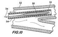
図5−10は、本発明によるスネア10を使用して動脈から塞栓を除去するための技術を示す。図5に示すように、凝血塊50の形状をした塞栓が動脈52に留まっている。カテーテル54が動脈52内へ挿入され、その先端56が押されて凝血塊50を越える。図6に示すように、スネア10は、カテーテル54から動脈52へ押し出され、開放された形状へ弾性的に拡張すると、その開口部20が凝血塊50のほうを向き、テザー24がカテーテル内へ導かれる。スネアとテザーは、処置を行う外科医の制御により、カテーテルを別々に移動させることができる。 5-10 illustrate a technique for removing emboli from an artery using a
さらに図7に示すように、カテーテル54は、部分的に後退させられて、その先端56をスネア10から離れた凝血塊50の反対側に配置する。次に、図8に示すように、スネア10はテザー24を使用してカテーテルの方へ引き戻される。凝血塊50は、先端23を有するタング21の作用により、動脈52から分離されて、開口部20へ進入し長尺状のバスケット12内に捕捉される。次に、図9に示すように、スネアと凝血塊は、カテーテルとともに動脈52から回収される。回収されると、スネア10は、図9に示すようにカテーテルから部分的に延び、或いは、図10に示すようにスネアと凝血塊50は、カテーテル内に引き込まれる。スネア10は、カテーテル内に進入すると、再び折り畳まれた形状をとる。好適にテーパ状をなすタング21が開口部20と連動して作動して開口部を収縮させ、スネア10の収縮も開始されて、スネア10がカテーテル内へ円滑に引き戻されて動脈52から抜去される。 As further shown in FIG. 7, the
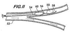
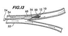
図11−13は、血管を閉塞する塞栓を除去する他の方法を示す。図11に示すように、凝血塊50は動脈52内に留まっている。先端56を有するカテーテル54が、ガイドワイヤ58上を導かれて凝血塊50の基端側にその先端56を配置する。カテーテル54は、先端56付近にバルーン60を有する。図12に示すように、バルーン60が膨張させられて動脈52を広げ、カテーテル54内のプッシャー要素62によりスネア10が押されて凝血塊50を越える。凝血塊50を越えると、スネア10は拡張し、その開口部20は凝血塊50のほうを向く。次に、図13に示すように、テザー24が使用されてスネア10をカテーテルの方へ引き寄せ、開口部20が凝血塊50を収容すると、凝血塊50はバスケット12内に捕捉される。バルーン60の拡張により、動脈52内に血液が環流し、その環流によりカテーテルの先端56に向かう凝血塊とスネアの移動が容易になる。バスケット12内に凝血塊が捕捉されると、バルーン60が収縮して、凝血塊を収容するカテーテル54とスネア10は、動脈52から回収される。 Figures 11-13 illustrate another method of removing an embolus that occludes a blood vessel. As shown in FIG. 11, the
図14及び15は、凝血塊50を動脈52から除去するためにスネア34を使用する方法を示す。図14に示すように、スネア34は、動脈52内に配置されたガイドワイヤ58に沿って導かれ、カテーテル54内に折り畳まれた形状において搬送される。カテーテル54の先端56は、凝血塊50を越えて配置されて、スネア34はカテーテルから押し出される。 FIGS. 14 and 15 illustrate a method of using the
図15に示すように、スネア34は、カテーテル54から解放されると開放された形状へ拡張する。軸方向に可撓性を有する領域42における弾性的な付勢力により、スネアを縦方向に拡張し、径方向に可撓性を有する領域44における弾性的な付勢力により、スネアは周方向へ拡張して、凝血塊50の方を向く開口部20を形成する。次に、テザー24が使用されてスネア34を凝血塊50の方へ引き寄せ、凝血塊50をサック46内に捕捉してからカテーテル54に沿って除去する。 As shown in FIG. 15, the
図16及び17はスネア10を示し、テザー64はバスケット12から分離されている、即ち、テザーはその長さに沿って限られた距離をバスケットとは関係なく移動することも可能である。分離されたテザー64は、中央の空間18を貫通して延びることが望ましく、閉鎖された端部22から外方へ突出する余分な長さ66を有する。テザー64の動きは、アイレット68,70により抑止され、アイレット68,70はタング21と閉鎖された端部22付近の側壁14上に配置され、中央の空間へ延びる。アイレット68,70は、タング21と側壁14から延びるループをなし、ガイド止め部の間のテザー64に取り付けられた制止体72と協働し、バスケット12に対してテザー64の移動を制限する。制止体72は、確実に係合を行うために(positive engagement)、アイレット68,70の径よりも大きい径を有する球形をなすことが望ましい。 FIGS. 16 and 17 show the
制止体72とアイレット68,70との間の協働により、テザー64がスネア10を押したり引いたりすることができ、それによりカテーテルを介して容易に操作されて、障害物を越えて所望の場所へ達する。図16に示すように、テザー64が、矢印74の方向においてスネア10の方へ押されると、制止体72はバスケット12の長さを超えて、アイレット70を係合する。アイレット70は、テザー64とバスケット12との間においてさらなる相対動作を防止する。テザー64をさらに押すことにより、バスケットを押し、例えば、バスケットをカテーテルから押し出して、動脈内の凝血塊を越える。制止体72がアイレット70に係合すると、テザー64をさらに押すことにより、ブレイドされた構造に伴うトレリス効果を利用し、バスケット12は、その閉鎖された端部22における力を受けて、縦方向に延びて径方向に収縮し、狭い開口部や他の限定された空間を通過できる。 The cooperation between the restraining
所望の位置、例えば、動脈内の凝血塊の近傍に到達すると、テザー64は、図17において矢印76に示される反対の方向へ引かれる。制止体72は、バスケット12の長さを超えてアイレット68を係合し、バスケット12は、凝血塊や他の捕捉されるべき障害物の方へ引っ張られる。バスケット12をその開放された端部から引っ張ることにより、その付勢に従って開放された形状をとり、凝血塊は開口部20から中央の空間18へ入る。 When the desired location is reached, for example, near the clot in the artery, the
本発明によるスネアは、患者に最小限度のリスクを伴って塞栓を除去することにより脳卒中の治療を行うための低侵襲的な方法を提供し、よって、さらなる脳の損傷や障害を引き起こすような、他の脳卒中や脳浮腫や興奮性毒素の解放といった二次作用の可能性を減少させる。 The snare according to the present invention provides a minimally invasive method for treating stroke by removing emboli with minimal risk to the patient, thus causing further brain damage and damage, Reduce the possibility of secondary effects such as the release of other strokes, brain edema and excitatory toxins.
Claims (19)
Translated fromJapanese中央の空間を取り巻き、かつ一端において開口部を有するとともに他端が閉鎖されているバスケットと、該開口部は該塞栓を収容するための該中央の空間へ到達できることと、
該開口部近傍の該バスケットに連結されて、そこから外方へ突出するタングと、該タングは該塞栓に係合して血管から分離させるための先端を有することと、
該先端を引いて該塞栓に係合させるために、該タングに連結されているテザーと、該テザーはバスケットの中央線からずれて配置されることとを特徴とする血管内スネア。An intravascular snare to capture and remove the embolus from the blood vessel,
A basket surrounding the central space and having an opening at one end and closed at the other end, the opening being accessible to the central space for receiving the embolus;
A tongue connected to the basket near the opening and projecting outward therefrom, the tongue having a tip for engaging the embolus and separating it from the blood vessel;
An intravascular snare characterized by a tether connected to the tongue for pulling the tip and engaging the embolus, and the tether being offset from the center line of the basket.
前記他端において前記バスケット上に配置された第2のアイレットと、これらのアイレットはテザーを受容するように構成されることと、
前記テザーに取り付けられるとともに、該第1のアイレットと第2のアイレットとの間に配置される制止体と、該制止体は、前記バスケットから離れる方向に前記テザーを引くと該第1のアイレットを係合し、これにより前記バスケットが前記テザーと同じ方向に引かれ、該制止体は、前記バスケットの方向に前記テザーを押すと第2のアイレットを係合し、これにより前記バスケットが前記テザーと同じ方向に押されることとを特徴とする請求項1に記載の血管内スネア。A first eyelet disposed on the tongue;
Second eyelets disposed on the basket at the other end, the eyelets being configured to receive tethers;
A restraining body that is attached to the tether and disposed between the first eyelet and the second eyelet, and the restraining body pulls the first eyelet when the tether is pulled away from the basket. Engaging, thereby pulling the basket in the same direction as the tether, and the restraining body engages the second eyelet when pushing the tether in the direction of the basket, thereby causing the basket to engage the tether. The intravascular snare according to claim 1, wherein the snare is pushed in the same direction.
中央の空間を取り巻き、かつ一端において開口部を有するとともに他端が閉鎖されているバスケットと、該開口部は該塞栓を収容するための該中央の空間へ到達できることと、
該開口部近傍の該バスケットに連結されて、そこから外方へ突出するタングと、該タングは該塞栓を係合して血管から分離させるための先端を有し、該タングとバスケットは、可撓性及び弾性を有してともにブレイドされた複数のモノフィラメントから形成され、該バスケットは該カテーテル内を通過して該血管内へ到達するように折り畳まれた形状に折り畳まれ、該モノフィラメントは、該カテーテルから解放されると該塞栓を収容するための開放された形状へ該バスケットを拡張すべく弾性的に付勢されることと、
該先端を引いて該塞栓に係合させるために、該タングに連結されているテザーと、該テザーはバスケットの中央線からずれて配置されることとを特徴とする血管内スネア。An intravascular snare for capturing and removing an embolus from a blood vessel, the snare being movable from a catheter for placement within the blood vessel;
A basket surrounding the central space and having an opening at one end and closed at the other end, the opening being accessible to the central space for receiving the embolus;
A tongue connected to the basket in the vicinity of the opening and projecting outward therefrom, and a tongue for engaging the embolus and separating it from the blood vessel. Formed from a plurality of monofilaments that are braided together with flexibility and elasticity, and the basket is folded into a folded configuration to pass through the catheter and into the blood vessel, Elastically biased to expand the basket to an open shape to accommodate the embolus when released from the catheter;
An intravascular snare characterized by a tether connected to the tongue for pulling the tip and engaging the embolus, and the tether being offset from the center line of the basket.
血管内にカテーテルを挿入して該塞栓を越えて該カテーテルの先端を配置する工程と、
該カテーテルから該スネアを配置し、該スネアを開放された形状へ拡張させる工程と、
該塞栓から該カテーテルを引き離して、該スネアから該塞栓の反対側に該カテーテルの先端を配置する工程と、
該スネアを該塞栓の方へ引き寄せる工程と、
該バスケット内に該塞栓を捕捉する工程と、
該血管から該カテーテルとスネアを抜去する工程とを含む方法。A method of removing an embolus that remains in a blood vessel using a snare placed from a catheter,
Inserting a catheter into the blood vessel and positioning the tip of the catheter beyond the embolus;
Disposing the snare from the catheter and expanding the snare to an open shape;
Pulling the catheter away from the embolus and placing the tip of the catheter on the opposite side of the embolus from the snare;
Drawing the snare toward the embolus;
Capturing the embolus in the basket;
Removing the catheter and snare from the blood vessel.
血管内にカテーテルを挿入して該塞栓の基端側に該カテーテルの先端を配置する工程と、
該血管を拡張してそこを通過する流れを遮断するために該バルーンを膨張させる工程と、
該カテーテルの先端から該塞栓の反対側の位置へ該スネアを配置する工程と、該スネアは該開放された形状へ拡張することと、
該スネアを該塞栓の方へ引き寄せる工程と、
該バスケット内の該塞栓を捕捉する工程と、
該バルーンを収縮させる工程と、
該血管から該カテーテルとスネアを抜去する工程とを含む方法。A method of removing an embolus that remains in a blood vessel using a snare placed from a catheter having a balloon placed near the tip,
Inserting a catheter into the blood vessel and disposing the distal end of the catheter on the proximal side of the embolus;
Inflating the balloon to dilate the blood vessel and block the flow therethrough;
Positioning the snare from the tip of the catheter to a position opposite the embolus; expanding the snare to the open shape;
Drawing the snare toward the embolus;
Capturing the embolus in the basket;
Deflating the balloon;
Removing the catheter and snare from the blood vessel.
Applications Claiming Priority (2)
| Application Number | Priority Date | Filing Date | Title |
|---|---|---|---|
| US50027703P | 2003-09-04 | 2003-09-04 | |
| PCT/US2004/028284WO2005025643A2 (en) | 2003-09-04 | 2004-08-31 | Endovascular snare for capture and removal of arterial emboli |
Publications (1)
| Publication Number | Publication Date |
|---|---|
| JP2007503918Atrue JP2007503918A (en) | 2007-03-01 |
Family
ID=34312187
Family Applications (1)
| Application Number | Title | Priority Date | Filing Date |
|---|---|---|---|
| JP2006525393APendingJP2007503918A (en) | 2003-09-04 | 2004-08-31 | Intravascular snare for capturing and removing arterial emboli |
Country Status (3)
| Country | Link |
|---|---|
| US (1) | US20050055047A1 (en) |
| JP (1) | JP2007503918A (en) |
| WO (1) | WO2005025643A2 (en) |
Cited By (3)
| Publication number | Priority date | Publication date | Assignee | Title |
|---|---|---|---|---|
| JP2013512072A (en)* | 2009-12-01 | 2013-04-11 | ゴア エンタープライズ ホールディングス,インコーポレイティド | Vascular system |
| WO2021246724A1 (en)* | 2020-06-02 | 2021-12-09 | 고려대학교 산학협력단 | Calculi removal device |
| JP2023529158A (en)* | 2020-06-05 | 2023-07-07 | グラビティ メディカル テクノロジー, インコーポレイテッド | Method and apparatus for restoring flow |
Families Citing this family (135)
| Publication number | Priority date | Publication date | Assignee | Title |
|---|---|---|---|---|
| US8425549B2 (en) | 2002-07-23 | 2013-04-23 | Reverse Medical Corporation | Systems and methods for removing obstructive matter from body lumens and treating vascular defects |
| US7686825B2 (en) | 2004-03-25 | 2010-03-30 | Hauser David L | Vascular filter device |
| US20060206200A1 (en) | 2004-05-25 | 2006-09-14 | Chestnut Medical Technologies, Inc. | Flexible vascular occluding device |
| CA2758946C (en) | 2004-05-25 | 2014-10-21 | Tyco Healthcare Group Lp | Vascular stenting for aneurysms |
| US8623067B2 (en) | 2004-05-25 | 2014-01-07 | Covidien Lp | Methods and apparatus for luminal stenting |
| US8617234B2 (en) | 2004-05-25 | 2013-12-31 | Covidien Lp | Flexible vascular occluding device |
| CA2565106C (en)* | 2004-05-25 | 2013-11-05 | Chestnut Medical Technologies, Inc. | Flexible vascular occluding device |
| US7931659B2 (en) | 2004-09-10 | 2011-04-26 | Penumbra, Inc. | System and method for treating ischemic stroke |
| US9655633B2 (en) | 2004-09-10 | 2017-05-23 | Penumbra, Inc. | System and method for treating ischemic stroke |
| JP2006087630A (en)* | 2004-09-22 | 2006-04-06 | Terumo Corp | Wire and medical appliance for removing foreign substance from blood vessel |
| AU2005332044B2 (en) | 2005-05-25 | 2012-01-19 | Covidien Lp | System and method for delivering and deploying and occluding device within a vessel |
| JP2009517124A (en)* | 2005-11-26 | 2009-04-30 | コンテゴ メディカル エルエルシー | Percutaneous transluminal angioplasty device with integrated embolic filter |
| US20070179519A1 (en)* | 2006-01-27 | 2007-08-02 | Wang Huisun | Stent delivery system to improve placement accuracy for self-expanding stent |
| EP1986568B1 (en) | 2006-02-03 | 2017-04-05 | Covidien LP | Methods and devices for restoring blood flow within blocked vasculature |
| US8152833B2 (en)* | 2006-02-22 | 2012-04-10 | Tyco Healthcare Group Lp | Embolic protection systems having radiopaque filter mesh |
| WO2008076330A1 (en) | 2006-12-15 | 2008-06-26 | Soteira, Inc. | Drills and methods for vertebrostenting |
| US10064635B2 (en) | 2007-04-17 | 2018-09-04 | Covidien Lp | Articulating retrieval devices |
| US8535334B2 (en)* | 2007-04-17 | 2013-09-17 | Lazarus Effect, Inc. | Complex wire formed devices |
| US10076346B2 (en) | 2007-04-17 | 2018-09-18 | Covidien Lp | Complex wire formed devices |
| US11202646B2 (en) | 2007-04-17 | 2021-12-21 | Covidien Lp | Articulating retrieval devices |
| US20100174309A1 (en)* | 2008-05-19 | 2010-07-08 | Mindframe, Inc. | Recanalization/revascularization and embolus addressing systems including expandable tip neuro-microcatheter |
| US8066757B2 (en)* | 2007-10-17 | 2011-11-29 | Mindframe, Inc. | Blood flow restoration and thrombus management methods |
| US9220522B2 (en) | 2007-10-17 | 2015-12-29 | Covidien Lp | Embolus removal systems with baskets |
| US10123803B2 (en) | 2007-10-17 | 2018-11-13 | Covidien Lp | Methods of managing neurovascular obstructions |
| US8926680B2 (en)* | 2007-11-12 | 2015-01-06 | Covidien Lp | Aneurysm neck bridging processes with revascularization systems methods and products thereby |
| US9198687B2 (en)* | 2007-10-17 | 2015-12-01 | Covidien Lp | Acute stroke revascularization/recanalization systems processes and products thereby |
| US8088140B2 (en) | 2008-05-19 | 2012-01-03 | Mindframe, Inc. | Blood flow restorative and embolus removal methods |
| US20100256600A1 (en)* | 2009-04-04 | 2010-10-07 | Ferrera David A | Neurovascular otw pta balloon catheter and delivery system |
| US11337714B2 (en) | 2007-10-17 | 2022-05-24 | Covidien Lp | Restoring blood flow and clot removal during acute ischemic stroke |
| JP2011507633A (en)* | 2007-12-19 | 2011-03-10 | マインドフレーム, インコーポレイテッド | Improved device and method for emboli removal during severe ischemic stroke |
| US8545526B2 (en)* | 2007-12-26 | 2013-10-01 | Lazarus Effect, Inc. | Retrieval systems and methods for use thereof |
| JP5457373B2 (en) | 2008-02-22 | 2014-04-02 | コヴィディエン リミテッド パートナーシップ | Device for blood flow recovery |
| WO2009155319A1 (en) | 2008-06-17 | 2009-12-23 | Soteira, Inc. | Devices and methods for fracture reduction |
| US9402707B2 (en) | 2008-07-22 | 2016-08-02 | Neuravi Limited | Clot capture systems and associated methods |
| EP2341845B1 (en)* | 2008-07-22 | 2016-01-06 | Neuravi Limited | Clot capture systems |
| EP2403583B1 (en) | 2009-03-06 | 2016-10-19 | Lazarus Effect, Inc. | Retrieval systems |
| WO2010111246A1 (en) | 2009-03-23 | 2010-09-30 | Soteira, Inc. | Devices and methods for vertebrostenting |
| EP2525861B1 (en) | 2010-01-22 | 2019-04-03 | Covidien LP | Retrieval systems |
| WO2012009675A2 (en) | 2010-07-15 | 2012-01-19 | Lazarus Effect, Inc. | Retrieval systems and methods for use thereof |
| WO2012049652A1 (en)* | 2010-10-15 | 2012-04-19 | Endogrowth (Proprietary) Limited | An inversible tubular member and a gripping device including such a member |
| ES2683943T3 (en) | 2010-10-22 | 2018-09-28 | Neuravi Limited | Clot capture and removal system |
| EP4566553A3 (en) | 2011-03-09 | 2025-08-06 | Neuravi Limited | A clot retrieval device for removing occlusive clot from a blood vessel |
| US11259824B2 (en) | 2011-03-09 | 2022-03-01 | Neuravi Limited | Clot retrieval device for removing occlusive clot from a blood vessel |
| US12076037B2 (en) | 2011-03-09 | 2024-09-03 | Neuravi Limited | Systems and methods to restore perfusion to a vessel |
| ES2683178T3 (en) | 2011-05-23 | 2018-09-25 | Covidien Lp | Extraction systems |
| US12096951B2 (en) | 2011-10-05 | 2024-09-24 | Penumbra, Inc. | System and method for treating ischemic stroke |
| WO2014047650A1 (en) | 2012-09-24 | 2014-03-27 | Inceptus Medical LLC | Device and method for treating vascular occlusion |
| US9301831B2 (en) | 2012-10-30 | 2016-04-05 | Covidien Lp | Methods for attaining a predetermined porosity of a vascular device |
| US9456834B2 (en) | 2012-10-31 | 2016-10-04 | Covidien Lp | Thrombectomy device with distal protection |
| US9452070B2 (en) | 2012-10-31 | 2016-09-27 | Covidien Lp | Methods and systems for increasing a density of a region of a vascular device |
| US9943427B2 (en) | 2012-11-06 | 2018-04-17 | Covidien Lp | Shaped occluding devices and methods of using the same |
| EP2732794A1 (en)* | 2012-11-14 | 2014-05-21 | Contego AB | Improved embolic protection device and method |
| US8784434B2 (en) | 2012-11-20 | 2014-07-22 | Inceptus Medical, Inc. | Methods and apparatus for treating embolism |
| US9157174B2 (en) | 2013-02-05 | 2015-10-13 | Covidien Lp | Vascular device for aneurysm treatment and providing blood flow into a perforator vessel |
| US20140257362A1 (en)* | 2013-03-07 | 2014-09-11 | St. Jude Medical, Cardiology Division, Inc. | Filtering and removing particulates from bloodstream |
| US9642635B2 (en) | 2013-03-13 | 2017-05-09 | Neuravi Limited | Clot removal device |
| WO2014140092A2 (en) | 2013-03-14 | 2014-09-18 | Neuravi Limited | Devices and methods for removal of acute blockages from blood vessels |
| ES2708786T3 (en) | 2013-03-14 | 2019-04-11 | Neuravi Ltd | Clot recovery device to remove occlusive clots from a blood vessel |
| US9433429B2 (en) | 2013-03-14 | 2016-09-06 | Neuravi Limited | Clot retrieval devices |
| US9402708B2 (en) | 2013-07-25 | 2016-08-02 | Covidien Lp | Vascular devices and methods with distal protection |
| US10238406B2 (en) | 2013-10-21 | 2019-03-26 | Inari Medical, Inc. | Methods and apparatus for treating embolism |
| US10285720B2 (en) | 2014-03-11 | 2019-05-14 | Neuravi Limited | Clot retrieval system for removing occlusive clot from a blood vessel |
| CN106470728A (en) | 2014-06-09 | 2017-03-01 | 因赛普特斯医学有限责任公司 | Retraction and suction device and related systems and methods for treating embolism |
| JP6595513B2 (en) | 2014-06-13 | 2019-10-23 | ニューラヴィ・リミテッド | Device for removal of acute occlusions from blood vessels |
| US10792056B2 (en) | 2014-06-13 | 2020-10-06 | Neuravi Limited | Devices and methods for removal of acute blockages from blood vessels |
| US10265086B2 (en) | 2014-06-30 | 2019-04-23 | Neuravi Limited | System for removing a clot from a blood vessel |
| US11253278B2 (en) | 2014-11-26 | 2022-02-22 | Neuravi Limited | Clot retrieval system for removing occlusive clot from a blood vessel |
| US10617435B2 (en) | 2014-11-26 | 2020-04-14 | Neuravi Limited | Clot retrieval device for removing clot from a blood vessel |
| EP3682821B1 (en) | 2014-11-26 | 2022-05-11 | Neuravi Limited | A clot retrieval device for removing an occlusive clot from a blood vessel |
| EP3256200A1 (en) | 2015-02-11 | 2017-12-20 | Covidien LP | Expandable tip medical devices and methods |
| WO2017019572A1 (en) | 2015-07-24 | 2017-02-02 | Ichor Vascular Inc. | Embolectomy system and methods of making same |
| US10342571B2 (en)* | 2015-10-23 | 2019-07-09 | Inari Medical, Inc. | Intravascular treatment of vascular occlusion and associated devices, systems, and methods |
| CN113796927B (en) | 2015-10-23 | 2025-03-04 | 伊纳里医疗公司 | Intravascular treatment of vascular occlusion and related devices, systems and methods |
| US9700332B2 (en)* | 2015-10-23 | 2017-07-11 | Inari Medical, Inc. | Intravascular treatment of vascular occlusion and associated devices, systems, and methods |
| WO2017147493A1 (en) | 2016-02-24 | 2017-08-31 | Incept, Llc | Enhanced flexibility neurovascular catheter |
| EP3500191B1 (en) | 2016-08-17 | 2020-09-23 | Neuravi Limited | A clot retrieval system for removing occlusive clot from a blood vessel |
| EP3509509B1 (en) | 2016-09-06 | 2021-03-31 | Neuravi Limited | A clot retrieval device for removing occlusive clot from a blood vessel |
| FI3528717T3 (en) | 2016-10-24 | 2024-08-09 | Inari Medical Inc | Devices for treating vascular occlusion |
| WO2018118706A1 (en)* | 2016-12-20 | 2018-06-28 | Lattouf Omar M | Clot retrievers and methods for deployment |
| US11737769B2 (en) | 2016-12-20 | 2023-08-29 | Omar M. Lattouf | Clot retrievers and methods for deployment |
| JP7264581B2 (en)* | 2017-01-06 | 2023-04-25 | インセプト、リミテッド、ライアビリティ、カンパニー | Antithrombotic coating for aneurysm treatment devices |
| US11191555B2 (en) | 2017-05-12 | 2021-12-07 | Covidien Lp | Retrieval of material from vessel lumens |
| US11129630B2 (en) | 2017-05-12 | 2021-09-28 | Covidien Lp | Retrieval of material from vessel lumens |
| US10722257B2 (en) | 2017-05-12 | 2020-07-28 | Covidien Lp | Retrieval of material from vessel lumens |
| US11298145B2 (en) | 2017-05-12 | 2022-04-12 | Covidien Lp | Retrieval of material from vessel lumens |
| US10709464B2 (en) | 2017-05-12 | 2020-07-14 | Covidien Lp | Retrieval of material from vessel lumens |
| WO2018232044A1 (en) | 2017-06-12 | 2018-12-20 | Covidien Lp | Tools for sheathing treatment devices and associated systems and methods |
| US10478322B2 (en) | 2017-06-19 | 2019-11-19 | Covidien Lp | Retractor device for transforming a retrieval device from a deployed position to a delivery position |
| US10575864B2 (en) | 2017-06-22 | 2020-03-03 | Covidien Lp | Securing element for resheathing an intravascular device and associated systems and methods |
| WO2019050765A1 (en) | 2017-09-06 | 2019-03-14 | Inari Medical, Inc. | Hemostasis valves and methods of use |
| US11154314B2 (en) | 2018-01-26 | 2021-10-26 | Inari Medical, Inc. | Single insertion delivery system for treating embolism and associated systems and methods |
| US11395665B2 (en) | 2018-05-01 | 2022-07-26 | Incept, Llc | Devices and methods for removing obstructive material, from an intravascular site |
| AU2019262972B2 (en) | 2018-05-01 | 2025-02-27 | Incept, Llc | Devices and methods for removing obstructive material from an intravascular site |
| US11471582B2 (en) | 2018-07-06 | 2022-10-18 | Incept, Llc | Vacuum transfer tool for extendable catheter |
| US11517335B2 (en) | 2018-07-06 | 2022-12-06 | Incept, Llc | Sealed neurovascular extendable catheter |
| CA3114285A1 (en) | 2018-08-13 | 2020-02-20 | Inari Medical, Inc. | System for treating embolism and associated devices and methods |
| US10842498B2 (en) | 2018-09-13 | 2020-11-24 | Neuravi Limited | Systems and methods of restoring perfusion to a vessel |
| US11406416B2 (en) | 2018-10-02 | 2022-08-09 | Neuravi Limited | Joint assembly for vasculature obstruction capture device |
| ES2910600T3 (en) | 2019-03-04 | 2022-05-12 | Neuravi Ltd | Powered Clot Recovery Catheter |
| US11766539B2 (en) | 2019-03-29 | 2023-09-26 | Incept, Llc | Enhanced flexibility neurovascular catheter |
| EP3791815B1 (en) | 2019-09-11 | 2024-06-26 | Neuravi Limited | Expandable mouth catheter |
| US11134859B2 (en) | 2019-10-15 | 2021-10-05 | Imperative Care, Inc. | Systems and methods for multivariate stroke detection |
| JP7638273B2 (en) | 2019-10-16 | 2025-03-03 | イナリ メディカル, インコーポレイテッド | Systems, devices and methods for treating vascular obstructions |
| US11712231B2 (en) | 2019-10-29 | 2023-08-01 | Neuravi Limited | Proximal locking assembly design for dual stent mechanical thrombectomy device |
| US11779364B2 (en) | 2019-11-27 | 2023-10-10 | Neuravi Limited | Actuated expandable mouth thrombectomy catheter |
| US11839725B2 (en) | 2019-11-27 | 2023-12-12 | Neuravi Limited | Clot retrieval device with outer sheath and inner catheter |
| US11517340B2 (en) | 2019-12-03 | 2022-12-06 | Neuravi Limited | Stentriever devices for removing an occlusive clot from a vessel and methods thereof |
| US11638637B2 (en) | 2019-12-18 | 2023-05-02 | Imperative Care, Inc. | Method of removing embolic material with thrombus engagement tool |
| US20210316127A1 (en) | 2019-12-18 | 2021-10-14 | Imperative Care, Inc. | Hemostasis valve |
| EP4076611A4 (en) | 2019-12-18 | 2023-11-15 | Imperative Care, Inc. | Methods and systems for treating venous thromboembolic disease |
| US11633198B2 (en) | 2020-03-05 | 2023-04-25 | Neuravi Limited | Catheter proximal joint |
| US11944327B2 (en) | 2020-03-05 | 2024-04-02 | Neuravi Limited | Expandable mouth aspirating clot retrieval catheter |
| CN113747934B (en) | 2020-03-10 | 2024-07-09 | 因普瑞缇夫护理公司 | Enhanced flexibility neurovascular catheter |
| US11883043B2 (en) | 2020-03-31 | 2024-01-30 | DePuy Synthes Products, Inc. | Catheter funnel extension |
| US11759217B2 (en) | 2020-04-07 | 2023-09-19 | Neuravi Limited | Catheter tubular support |
| US11717308B2 (en) | 2020-04-17 | 2023-08-08 | Neuravi Limited | Clot retrieval device for removing heterogeneous clots from a blood vessel |
| US11730501B2 (en) | 2020-04-17 | 2023-08-22 | Neuravi Limited | Floating clot retrieval device for removing clots from a blood vessel |
| US11871946B2 (en) | 2020-04-17 | 2024-01-16 | Neuravi Limited | Clot retrieval device for removing clot from a blood vessel |
| US11737771B2 (en) | 2020-06-18 | 2023-08-29 | Neuravi Limited | Dual channel thrombectomy device |
| US11937836B2 (en) | 2020-06-22 | 2024-03-26 | Neuravi Limited | Clot retrieval system with expandable clot engaging framework |
| US11439418B2 (en) | 2020-06-23 | 2022-09-13 | Neuravi Limited | Clot retrieval device for removing clot from a blood vessel |
| US11395669B2 (en) | 2020-06-23 | 2022-07-26 | Neuravi Limited | Clot retrieval device with flexible collapsible frame |
| US11207497B1 (en) | 2020-08-11 | 2021-12-28 | Imperative Care, Inc. | Catheter with enhanced tensile strength |
| US11864781B2 (en) | 2020-09-23 | 2024-01-09 | Neuravi Limited | Rotating frame thrombectomy device |
| CN112607067B (en)* | 2020-12-11 | 2022-07-29 | 北京空间机电研究所 | A multi-target acquisition switching system that can be used for space tethered control acquisition |
| US11937837B2 (en) | 2020-12-29 | 2024-03-26 | Neuravi Limited | Fibrin rich / soft clot mechanical thrombectomy device |
| US12029442B2 (en) | 2021-01-14 | 2024-07-09 | Neuravi Limited | Systems and methods for a dual elongated member clot retrieval apparatus |
| US11872354B2 (en) | 2021-02-24 | 2024-01-16 | Neuravi Limited | Flexible catheter shaft frame with seam |
| US12064130B2 (en) | 2021-03-18 | 2024-08-20 | Neuravi Limited | Vascular obstruction retrieval device having sliding cages pinch mechanism |
| US11974764B2 (en) | 2021-06-04 | 2024-05-07 | Neuravi Limited | Self-orienting rotating stentriever pinching cells |
| US20230052862A1 (en) | 2021-08-12 | 2023-02-16 | Imperative Care, Inc. | Sterile packaging assembly for robotic interventional device |
| US11937839B2 (en) | 2021-09-28 | 2024-03-26 | Neuravi Limited | Catheter with electrically actuated expandable mouth |
| USD1077996S1 (en) | 2021-10-18 | 2025-06-03 | Imperative Care, Inc. | Inline fluid filter |
| US12011186B2 (en) | 2021-10-28 | 2024-06-18 | Neuravi Limited | Bevel tip expandable mouth catheter with reinforcing ring |
| EP4463083A1 (en) | 2022-01-11 | 2024-11-20 | Inari Medical, Inc. | Devices for removing clot material from intravascularly implanted devices, and associated systems and methods |
Family Cites Families (10)
| Publication number | Priority date | Publication date | Assignee | Title |
|---|---|---|---|---|
| US4706671A (en)* | 1985-05-02 | 1987-11-17 | Weinrib Harry P | Catheter with coiled tip |
| US5895398A (en)* | 1996-02-02 | 1999-04-20 | The Regents Of The University Of California | Method of using a clot capture coil |
| US6066158A (en)* | 1996-07-25 | 2000-05-23 | Target Therapeutics, Inc. | Mechanical clot encasing and removal wire |
| US5972019A (en)* | 1996-07-25 | 1999-10-26 | Target Therapeutics, Inc. | Mechanical clot treatment device |
| US5814064A (en)* | 1997-03-06 | 1998-09-29 | Scimed Life Systems, Inc. | Distal protection device |
| WO1999039648A1 (en)* | 1998-02-10 | 1999-08-12 | Dubrul William R | Entrapping apparatus and method for use |
| US6602265B2 (en)* | 1998-02-10 | 2003-08-05 | Artemis Medical, Inc. | Tissue separation medical device and method |
| US6511492B1 (en)* | 1998-05-01 | 2003-01-28 | Microvention, Inc. | Embolectomy catheters and methods for treating stroke and other small vessel thromboembolic disorders |
| US6589263B1 (en)* | 1999-07-30 | 2003-07-08 | Incept Llc | Vascular device having one or more articulation regions and methods of use |
| US6402771B1 (en)* | 1999-12-23 | 2002-06-11 | Guidant Endovascular Solutions | Snare |
- 2004
- 2004-08-31JPJP2006525393Apatent/JP2007503918A/enactivePending
- 2004-08-31WOPCT/US2004/028284patent/WO2005025643A2/ennot_activeApplication Discontinuation
- 2004-09-07USUS10/935,521patent/US20050055047A1/ennot_activeAbandoned
Cited By (3)
| Publication number | Priority date | Publication date | Assignee | Title |
|---|---|---|---|---|
| JP2013512072A (en)* | 2009-12-01 | 2013-04-11 | ゴア エンタープライズ ホールディングス,インコーポレイティド | Vascular system |
| WO2021246724A1 (en)* | 2020-06-02 | 2021-12-09 | 고려대학교 산학협력단 | Calculi removal device |
| JP2023529158A (en)* | 2020-06-05 | 2023-07-07 | グラビティ メディカル テクノロジー, インコーポレイテッド | Method and apparatus for restoring flow |
Also Published As
| Publication number | Publication date |
|---|---|
| WO2005025643A3 (en) | 2005-06-23 |
| WO2005025643A2 (en) | 2005-03-24 |
| US20050055047A1 (en) | 2005-03-10 |
Similar Documents
| Publication | Publication Date | Title |
|---|---|---|
| JP2007503918A (en) | Intravascular snare for capturing and removing arterial emboli | |
| US12251120B2 (en) | Devices and methods for treating vascular occlusion | |
| US12295601B2 (en) | Inverting thrombectomy apparatuses having enhanced tracking | |
| US11504150B2 (en) | Intravascular thromboembolectomy devices and methods | |
| US11871949B2 (en) | Clot engagement and removal system | |
| US11896251B2 (en) | Inverting thrombectomy apparatuses and methods of use | |
| US11559320B2 (en) | Inverting thrombectomy apparatuses and methods | |
| US20210228224A1 (en) | Thrombectomy devices and methods | |
| CN112638317B (en) | Integrated thrombectomy and filtration device and method of use | |
| US12076260B2 (en) | Method and apparatus for stent delivery | |
| US8568465B2 (en) | Device for rechanneling a cavity, organ path or vessel | |
| US20190142617A1 (en) | Releasable Delivery System | |
| JP6463132B2 (en) | Device for removing obstructions | |
| US8366737B2 (en) | Expandable emboli filter and thrombectomy device | |
| US20160015403A1 (en) | Medical retrieval devices and methods | |
| US20110202088A1 (en) | Embolectomy Device With Optional Vibrator | |
| US20140222060A1 (en) | Guidewire stop | |
| EP3570778B1 (en) | An apparatus for clot and plaque retracting | |
| US20230057026A1 (en) | Clot removal device and method |