JP2007503866A - Intradermal injection device - Google Patents
Intradermal injection deviceDownload PDFInfo
- Publication number
- JP2007503866A JP2007503866AJP2006524607AJP2006524607AJP2007503866AJP 2007503866 AJP2007503866 AJP 2007503866AJP 2006524607 AJP2006524607 AJP 2006524607AJP 2006524607 AJP2006524607 AJP 2006524607AJP 2007503866 AJP2007503866 AJP 2007503866A
- Authority
- JP
- Japan
- Prior art keywords
- protrusion
- channel
- needle cannula
- holder
- proximal end
- Prior art date
- Legal status (The legal status is an assumption and is not a legal conclusion. Google has not performed a legal analysis and makes no representation as to the accuracy of the status listed.)
- Granted
Links
Images


Classifications
- A—HUMAN NECESSITIES
- A61—MEDICAL OR VETERINARY SCIENCE; HYGIENE
- A61M—DEVICES FOR INTRODUCING MEDIA INTO, OR ONTO, THE BODY; DEVICES FOR TRANSDUCING BODY MEDIA OR FOR TAKING MEDIA FROM THE BODY; DEVICES FOR PRODUCING OR ENDING SLEEP OR STUPOR
- A61M5/00—Devices for bringing media into the body in a subcutaneous, intra-vascular or intramuscular way; Accessories therefor, e.g. filling or cleaning devices, arm-rests
- A61M5/46—Devices for bringing media into the body in a subcutaneous, intra-vascular or intramuscular way; Accessories therefor, e.g. filling or cleaning devices, arm-rests having means for controlling depth of insertion
- A—HUMAN NECESSITIES
- A61—MEDICAL OR VETERINARY SCIENCE; HYGIENE
- A61M—DEVICES FOR INTRODUCING MEDIA INTO, OR ONTO, THE BODY; DEVICES FOR TRANSDUCING BODY MEDIA OR FOR TAKING MEDIA FROM THE BODY; DEVICES FOR PRODUCING OR ENDING SLEEP OR STUPOR
- A61M5/00—Devices for bringing media into the body in a subcutaneous, intra-vascular or intramuscular way; Accessories therefor, e.g. filling or cleaning devices, arm-rests
- A61M5/178—Syringes
- A61M5/31—Details
- A61M5/32—Needles; Details of needles pertaining to their connection with syringe or hub; Accessories for bringing the needle into, or holding the needle on, the body; Devices for protection of needles
- A61M5/34—Constructions for connecting the needle, e.g. to syringe nozzle or needle hub
- A61M5/343—Connection of needle cannula to needle hub, or directly to syringe nozzle without a needle hub
- A—HUMAN NECESSITIES
- A61—MEDICAL OR VETERINARY SCIENCE; HYGIENE
- A61M—DEVICES FOR INTRODUCING MEDIA INTO, OR ONTO, THE BODY; DEVICES FOR TRANSDUCING BODY MEDIA OR FOR TAKING MEDIA FROM THE BODY; DEVICES FOR PRODUCING OR ENDING SLEEP OR STUPOR
- A61M5/00—Devices for bringing media into the body in a subcutaneous, intra-vascular or intramuscular way; Accessories therefor, e.g. filling or cleaning devices, arm-rests
- A61M5/178—Syringes
- A61M5/31—Details
- A61M2005/3103—Leak prevention means for distal end of syringes, i.e. syringe end for mounting a needle
- A61M2005/3107—Leak prevention means for distal end of syringes, i.e. syringe end for mounting a needle for needles
- A61M2005/311—Plugs, i.e. sealing rods or stylets closing the bore of needles
- A—HUMAN NECESSITIES
- A61—MEDICAL OR VETERINARY SCIENCE; HYGIENE
- A61M—DEVICES FOR INTRODUCING MEDIA INTO, OR ONTO, THE BODY; DEVICES FOR TRANSDUCING BODY MEDIA OR FOR TAKING MEDIA FROM THE BODY; DEVICES FOR PRODUCING OR ENDING SLEEP OR STUPOR
- A61M5/00—Devices for bringing media into the body in a subcutaneous, intra-vascular or intramuscular way; Accessories therefor, e.g. filling or cleaning devices, arm-rests
- A61M5/178—Syringes
- A61M5/28—Syringe ampoules or carpules, i.e. ampoules or carpules provided with a needle
- A—HUMAN NECESSITIES
- A61—MEDICAL OR VETERINARY SCIENCE; HYGIENE
- A61M—DEVICES FOR INTRODUCING MEDIA INTO, OR ONTO, THE BODY; DEVICES FOR TRANSDUCING BODY MEDIA OR FOR TAKING MEDIA FROM THE BODY; DEVICES FOR PRODUCING OR ENDING SLEEP OR STUPOR
- A61M5/00—Devices for bringing media into the body in a subcutaneous, intra-vascular or intramuscular way; Accessories therefor, e.g. filling or cleaning devices, arm-rests
- A61M5/178—Syringes
- A61M5/31—Details
- A61M5/315—Pistons; Piston-rods; Guiding, blocking or restricting the movement of the rod or piston; Appliances on the rod for facilitating dosing ; Dosing mechanisms
- A61M5/31511—Piston or piston-rod constructions, e.g. connection of piston with piston-rod
- A—HUMAN NECESSITIES
- A61—MEDICAL OR VETERINARY SCIENCE; HYGIENE
- A61M—DEVICES FOR INTRODUCING MEDIA INTO, OR ONTO, THE BODY; DEVICES FOR TRANSDUCING BODY MEDIA OR FOR TAKING MEDIA FROM THE BODY; DEVICES FOR PRODUCING OR ENDING SLEEP OR STUPOR
- A61M5/00—Devices for bringing media into the body in a subcutaneous, intra-vascular or intramuscular way; Accessories therefor, e.g. filling or cleaning devices, arm-rests
- A61M5/178—Syringes
- A61M5/31—Details
- A61M5/32—Needles; Details of needles pertaining to their connection with syringe or hub; Accessories for bringing the needle into, or holding the needle on, the body; Devices for protection of needles
- A61M5/3205—Apparatus for removing or disposing of used needles or syringes, e.g. containers; Means for protection against accidental injuries from used needles
- A61M5/321—Means for protection against accidental injuries by used needles
- A—HUMAN NECESSITIES
- A61—MEDICAL OR VETERINARY SCIENCE; HYGIENE
- A61M—DEVICES FOR INTRODUCING MEDIA INTO, OR ONTO, THE BODY; DEVICES FOR TRANSDUCING BODY MEDIA OR FOR TAKING MEDIA FROM THE BODY; DEVICES FOR PRODUCING OR ENDING SLEEP OR STUPOR
- A61M5/00—Devices for bringing media into the body in a subcutaneous, intra-vascular or intramuscular way; Accessories therefor, e.g. filling or cleaning devices, arm-rests
- A61M5/178—Syringes
- A61M5/31—Details
- A61M5/32—Needles; Details of needles pertaining to their connection with syringe or hub; Accessories for bringing the needle into, or holding the needle on, the body; Devices for protection of needles
- A61M5/34—Constructions for connecting the needle, e.g. to syringe nozzle or needle hub
- A61M5/349—Constructions for connecting the needle, e.g. to syringe nozzle or needle hub using adhesive bond or glues
- A—HUMAN NECESSITIES
- A61—MEDICAL OR VETERINARY SCIENCE; HYGIENE
- A61M—DEVICES FOR INTRODUCING MEDIA INTO, OR ONTO, THE BODY; DEVICES FOR TRANSDUCING BODY MEDIA OR FOR TAKING MEDIA FROM THE BODY; DEVICES FOR PRODUCING OR ENDING SLEEP OR STUPOR
- A61M5/00—Devices for bringing media into the body in a subcutaneous, intra-vascular or intramuscular way; Accessories therefor, e.g. filling or cleaning devices, arm-rests
- A61M5/42—Devices for bringing media into the body in a subcutaneous, intra-vascular or intramuscular way; Accessories therefor, e.g. filling or cleaning devices, arm-rests having means for desensitising skin, for protruding skin to facilitate piercing, or for locating point where body is to be pierced
- A61M5/425—Protruding skin to facilitate piercing, e.g. vacuum cylinders, vein immobilising means
Landscapes
- Health & Medical Sciences (AREA)
- Vascular Medicine (AREA)
- Engineering & Computer Science (AREA)
- Anesthesiology (AREA)
- Biomedical Technology (AREA)
- Heart & Thoracic Surgery (AREA)
- Hematology (AREA)
- Life Sciences & Earth Sciences (AREA)
- Animal Behavior & Ethology (AREA)
- General Health & Medical Sciences (AREA)
- Public Health (AREA)
- Veterinary Medicine (AREA)
- Infusion, Injection, And Reservoir Apparatuses (AREA)
Abstract
Translated fromJapaneseDescription
Translated fromJapanese本発明は、皮内注射装置に関する。 The present invention relates to an intradermal injection device.
(関連出願)
本出願は、2003年8月28日に出願された米国仮特許出願第60/498,508号に基づく優先権を主張するものである。(Related application)
This application claims priority from US Provisional Patent Application No. 60 / 498,508, filed Aug. 28, 2003.
薬剤物質は、筋肉、皮下組織内、または、表皮および真皮内への注射(皮内注射とも呼ばれる)によって患者の身体内に送達され得る。特定の薬剤物質の効力は、薬剤が皮内に送達されるときに変化し得る。幾つかの場合において、皮内送達は、患者にとってはより有利となり得る。個人間でおよび同じ個人内の身体の異なる部位での両方において、皮膚の厚さはかなり異なる。一般に、皮膚の外側の層である表皮は、50ミクロンから200ミクロンまでの範囲の厚さを有し、真皮、すなわち皮膚の内側のより厚い層は、1.5mmから3.5mmまでの範囲の厚さを有する。従って、約3mmより深く皮膚に貫入する針カニューレは、皮膚の真皮層を貫通する可能性があり、その結果、注射が皮下領域になされ、特に皮内に送達されるべき物質が皮下注射として指示されていなかった場合には、不適当な免疫反応がおこる可能性がある。また、針カニューレは、物質を送達するにはあまりにも浅過ぎる深さで皮膚に貫入し、注射部位からの物質の逆流に起因する「注射漏れ(wet injection)」として当該技術分野において一般的に知られている事態がおこりうる。 The drug substance can be delivered into the patient's body by intramuscular, subcutaneous tissue, or injection into the epidermis and dermis (also referred to as intradermal injection). The potency of a particular drug substance can change when the drug is delivered intradermally. In some cases, intradermal delivery may be more advantageous for the patient. Skin thickness varies considerably between individuals and at different parts of the body within the same individual. In general, the epidermis, the outer layer of the skin, has a thickness in the range of 50 microns to 200 microns, and the dermis, the thicker layer on the inner side of the skin, in the range of 1.5 mm to 3.5 mm. Has a thickness. Thus, a needle cannula that penetrates the skin deeper than about 3 mm can penetrate the dermal layer of the skin, so that the injection is made into the subcutaneous region, in particular the substance to be delivered intradermally is indicated as a subcutaneous injection. If not, an inappropriate immune response may occur. Needle cannulas also penetrate the skin at a depth that is too shallow to deliver the substance and is commonly referred to in the art as “wet injection” due to backflow of the substance from the injection site. A known situation can occur.
マントゥー(Mantoux)処置として一般に呼ばれている、皮内注射を行う標準的な処置は行うのが難しく、その処置を用いた皮内注射投与の出来は、注射装置を用いる人員の経験と技術によって左右される。マントゥー処置では、注射装置のユーザが皮膚を伸ばし、針ベベルを上方に向くように方向付け、26ゲージの短いベベルの針カニューレを挿入して、患者の皮膚の中に0.5mlかまたはそれ以下の量の薬剤物質を送達しなければならない。この処置のあいだ、薬剤物質が置かれまたはそうでなければ収容される水疱または膨疹を形成するために、針カニューレは、患者の皮膚に対して約10°乃至15°の角度をなすように維持されなければならない。上述の技術は行うのが難しく、一般的には訓練をつんだ看護師または医師の注意を必要とする。約3mmより深くに針を挿入すると、カニューレを通して放出される薬剤物質が患者の皮下組織内に注射されることになるので、通常は、皮内注射は失敗となる。 The standard procedure of performing intradermal injection, commonly referred to as Mantoux treatment, is difficult to perform and the ability to administer intradermal injection using that procedure depends on the experience and skill of the personnel using the injection device. It depends. In a mantu procedure, the user of the injection device stretches the skin, directs the needle bevel upwards, inserts a 26 gauge short beveled needle cannula and inserts 0.5 ml or less into the patient's skin. A quantity of drug substance must be delivered. During this procedure, the needle cannula is maintained at an angle of about 10 ° to 15 ° to the patient's skin to form a blister or wheal where the drug substance is placed or otherwise contained. It must be. The techniques described above are difficult to perform and generally require the attention of a trained nurse or doctor. Intradermal injection usually fails because insertion of the needle deeper than about 3 mm will result in the drug substance released through the cannula being injected into the patient's subcutaneous tissue.
両方とも本発明の譲渡人に譲渡された、2002年6月6日に公開された特許文献1および2002年12月17日に発行された特許文献2に開示されているように、皮内針アセンブリは、患者の皮膚に注射する薬剤物質を格納できるリザーバを有する事前充填可能な容器と共に使用するために開発されてきた。針カニューレは、事前充填可能な容器により支持されており、容器から離れるように延びる前方先端部を有する。皮内針アセンブリは、事前充填可能な容器に固定することができるリミッタを含み、該リミッタは、針カニューレを取り囲み、針カニューレの軸にほぼ直角な平面内に延びるほぼ平坦な皮膚係合面を備える。平坦な皮膚係合面は、皮内注射の投与の際に患者の皮膚に接触して支えるようになっている。針の前方先端部は、約0.5mm乃至3mmの長さだけ皮膚係合面を越えて延びる。従って、リミッタは、針が患者の皮膚の真皮層に貫入するのを制限して、薬剤物質が患者の真皮層に注射されるようにする。 Both intradermal needles, as disclosed in US Pat. No. 6,037,028 published on Jun. 6, 2002 and U.S. Pat. No. 6,017,021 issued on Dec. 17, 2002, both assigned to the assignee of the present invention. The assembly has been developed for use with a prefillable container having a reservoir capable of storing a drug substance for injection into a patient's skin. The needle cannula is supported by a prefillable container and has a forward tip that extends away from the container. The intradermal needle assembly includes a limiter that can be secured to a prefillable container, the limiter surrounding a needle cannula and having a substantially flat skin engaging surface extending in a plane generally perpendicular to the axis of the needle cannula. Prepare. The flat skin engaging surface is adapted to contact and support the patient's skin during intradermal injection administration. The front tip of the needle extends beyond the skin engaging surface by a length of about 0.5 mm to 3 mm. Thus, the limiter limits the penetration of the needle into the dermis layer of the patient's skin so that the drug substance is injected into the patient's dermis layer.
本発明は、開放末端部および皮膚係合面が規定された基端部と、薬剤物質を収容するために前記基端部および末端部間に規定されたリザーバと、前記基端部に規定され、且つ、皮膚係合面を通して、そこからリザーバまで末端方向に延びるチャネルと、を有するユニット本体を含む皮内注射装置に向けられている。さらに、その装置は、鋭利にされた基端部および末端部を有する針カニューレを含む。針カニューレは、末端部がリザーバと連通しており、針カニューレの基端部が約0.5mmから約3.0mmまでの範囲内の長さだけ皮膚係合面から延びて、皮膚係合面が患者の皮膚の真皮層への針カニューレの基端部の貫入を制限するようになった状態で、チャネルに固定されている。 The present invention includes a proximal end having an open distal end and a skin engaging surface defined therein, a reservoir defined between the proximal end and the distal end for receiving a drug substance, and a proximal end defined in the proximal end. And an intradermal injection device including a unit body having a channel extending distally therethrough through the skin engaging surface to the reservoir. In addition, the device includes a needle cannula having a sharpened proximal end and a distal end. The needle cannula has a distal end communicating with the reservoir, and the proximal end of the needle cannula extends from the skin engaging surface for a length in the range of about 0.5 mm to about 3.0 mm. Is secured to the channel in a manner that limits the penetration of the proximal end of the needle cannula into the dermal layer of the patient's skin.
本発明のさらなる態様において、第1の表面部分から先端方向に延びる突出部が、装置本体の基端部に設けられている。突出部は環状であり、チャネルを取り囲むことが好ましい。突出部は、装置と患者の皮膚との間の良好な境界面を形成することによって注射プロセスを助け、注射プロセスのあいだの注射部位からの漏れを制限する。 In a further aspect of the present invention, a protrusion extending in the distal direction from the first surface portion is provided at the proximal end of the apparatus main body. The protrusion is annular and preferably surrounds the channel. The protrusions assist the injection process by creating a good interface between the device and the patient's skin and limit leakage from the injection site during the injection process.
本発明のさらに別の態様において、ユニット本体を含む薬剤ホルダを設けて、針カニューレをそれに接合することができる。 In yet another aspect of the present invention, a drug holder including a unit body can be provided and a needle cannula can be joined thereto.
本発明では、針カニューレは、注射本体または薬剤ホルダに「ステーク」接合または直接接合されて、別個のリミッタを使用することなく、皮内注射装置を形成する利点を有する。他の用途が考えられるが、本発明は、ガラスの事前充填可能な皮内注射器として使用されるのに特に適している。 In the present invention, the needle cannula has the advantage of being “stake” joined or directly joined to the injection body or drug holder to form an intradermal injection device without the use of a separate limiter. Although other applications are envisioned, the present invention is particularly suitable for use as a glass prefillable intradermal syringe.
ここで用いられる「末端の」とは、患者から離れるかまたは最も遠くに位置する部分または方向のことをいい、一方、「基端の」とは、患者に向うまたは患者の最も近くに位置する部分または方向のことをいう。また、「薬剤物質」とは、あらゆる目的のために患者の身体に注射可能なあらゆる物質のことをいうために例示するものであり、制限する意味ではないようにここでは用いられている。患者への言及は、あらゆる生き物、人間または動物に対するものとすることができる。 As used herein, “distal” refers to the portion or orientation that is farthest or farthest from the patient, while “proximal” is located towards or closest to the patient. A part or direction. In addition, “drug substance” is exemplified to refer to any substance that can be injected into a patient's body for any purpose, and is used herein in a non-limiting sense. Reference to a patient can be for any living creature, human or animal.
本発明のこれらのおよび他の特徴は、以下の詳細な説明および添付図面を精査することによってより良く理解されるであろう。 These and other features of the present invention will be better understood by reviewing the following detailed description and the accompanying drawings.
図面においては、それらは縮尺で示されたものではなく、同じ参照番号が、幾つかの図面全体を通して同様の要素を示す。 In the drawings, they are not drawn to scale, and the same reference numbers indicate similar elements throughout the several views.
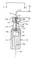
図1−図3は、本発明の実施形態に従って構成された皮内注射装置100を描いている。注射装置100は、バレル20と、フランジ22を備えた開放末端部40と、基端部30と、その間に形成されるリザーバ24とを有する本体10から構成される注射器であることが好ましい。注射装置100がエンド・ユーザに提供される前に、薬剤物質をリザーバ24に入れることができる。注射装置100はさらに、リザーバ24内に摺動するように且つリザーバ24内を密封するように提供されたプランジャ80と、薬剤物質をリザーバから放出させるためにリザーバ24内でのプランジャ80の移動を容易にするべくプランジャ80に固定されたプランジャ・ロッド90とを含む。 1-3 depict an
本体10は、基端部30付近で狭窄して、本体10の基端部30において形成されるリミッタ50を支持するネック28を形成する。ネック28は、特に末端から先端の方向に収束するようにテーパされていることが好ましい。バレル20とネック28との間の外径の緩やかな変化に適応するように第1の遷移部32を設けることができ、ネック28とリミッタ50との間の外径の緩やかな変化に適応するように第2の遷移部34を設けることができる。種々の要素間の急な、例えば直角といった遷移部が形成されるのを避けるために、遷移部32、34を、面取りし、丸みを与えまたはその他の方法でなめらかにすることができる。 The
リミッタ50は、その基端部において、注射装置100の使用の際に患者の皮膚に接触する皮膚係合面52を形成する。リミッタ50および皮膚係合面52は、本体10と一体形成されている。皮膚係合面52は、平坦に形成されてもよいし、或いはこれらに限定されるものではないが、この開示の全体を引用によりここに組み入れる同時継続の特許文献3において開示された、そうした表面形状を含めて、任意の公知の形状で形成されてもよい。 The
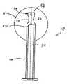
図5を参照すると、リミッタ50は、シリンダ形状を有することが好ましく、11mmより小さいかまたはそれに等しい、より好ましくは5.5mmより小さいかまたはそれに等しい外径dを規定する。皮膚係合面52と側面56との間に急な遷移部が形成されるのを避けるために、リミッタ50の皮膚係合面52と側面56との交差部に形成された外周部54を、面取りし、丸みを与えまたはその他の方法でなめらかにすることが好ましい。 Referring to FIG. 5, the
チャネル26は、皮膚係合面52を貫通して末端方向に延びて、リザーバ24と連通する。チャネル26は、皮膚係合面52により形成される平面に対してほぼ直角な中心縦軸を有することが好ましい。チャネル26は、一定の直径を有することもできるし、或いは針カニューレの外径にほぼ合わせられた直径から、針カニューレの外径より大きいサイズにまで増大した直径までサイズが異なる直径を有することもできる。いずれの場合においても、チャネル26の一部は、以下でさらに詳細に説明されるように、針カニューレを収容する大きさおよび形状の直径を有することが好ましい。様々な直径のチャネル26については、皮膚係合面52に最も近いチャネル26の端部が、接着剤を受け入れて針カニューレをチャネル26に固定するためにチャネル26の他の部分より大きな直径を有することが好ましい。同様に、様々な直径の形状については、チャネル26の断面外形は、テーパがつけられていてもよいし、段付きとされてもよいし、或いはチャネル26の直径の変化を可能にするその他のあらゆる形状とされてもよい。例えば図2に示す好ましい実施形態においては、チャネル26は、皮膚係合面52付近に位置する第1の部分126と、リザーバ24付近に位置する第2の部分226とを有する。第1の部分126は、第2の部分226の直径より大きい直径を有し、第2の部分226の直径は、本発明の注射装置100の一部として形成された針カニューレの外径とほぼ同じになるように選択されることが好ましい。種々のゲージの針カニューレの外径が、当該技術分野において公知であり、第2の部分226は、それに応じた大きさにすることができる。チャネル26は、任意的に、リザーバ24の底面124とチャネル26の第2の部分226との間に少なくとも部分的な遷移部を形成するために、リザーバ24に隣接して設けられた第3の部分336を含むことができる。チャネル26の第1の部分126と第2の部分226との間にも同様の遷移部を形成することができる。 The
図4および図5に示すように、薬剤ホルダとして機能することができる本体10は、単独で形成することができる。針カニューレ70と組み合わされた本体10が、注射装置100を形成する。 As shown in FIGS. 4 and 5, the
図1および図2を参照すると、針カニューレ70は、チャネル26内の本体10の基端部30において支持され、リザーバ24内またはその付近に位置する末端部74と、皮膚係合面52から所定の長さd2だけ延びる、好ましくは鋭利にされた前方先端部72とを含む。好ましい実施形態において、長さd2は、およそ0.5mmから3mmまでの範囲である。長さd2は、(皮膚係合面52が平坦であるかどうかにかかわらず)皮膚係合面52の同一平面部分により規定される平面から測定されることが好ましく、長さd2は、皮膚係合面52の最も基端の部分から測定されることがより好ましい。同一平面部分は、針カニューレ70の周りに連続的にまたは不連続的に配置することができる。皮膚係合面52は、患者の皮膚に係合して、注射のあいだに均一な圧力リングが針カニューレ70の周りに生成されるように形成されることが好ましい。圧力リングは、注射プロセスのあいだに注射部位から流体が漏れるのを減少させるのに役立つ。With reference to FIGS. 1 and 2, the
末端部74は、リザーバ24と流体連通しており、針カニューレ70は、リザーバ24からの流体経路を与え、該流体経路を通って薬剤物質が注射装置100から放出され、患者の皮膚の皮内領域内に注射され得る。図2においては参照番号76として示されている針カニューレ70の中心軸は、皮膚係合面52により規定される平面、特に長さd2が上述のように測定される平面に対して所定の角度をなすように配置されている。好ましい実施形態において、その所定の角度は、およそ90°である。他の角度関係も、本発明によりおよび本発明の範囲および精神内で考えられる。さらに、針カニューレの中心軸76と皮膚係合面52の平面との間の角度関係は、チャネル26における針カニューレ70の配置の違い、皮膚係合面52の向きの違い、またはその両方の違いにより規定され得る。The
針カニューレ70は、特に本体10がガラスで形成されている場合には、適切な接着剤60(例えば、図3参照)を用いて本体10に且つチャネル26内に固定される。好ましい実施形態において、接着剤60は、熱または紫外線硬化可能である。針カニューレ70をチャネル26内に固定するのに使用される接着剤60の量は、皮膚係合面52の平坦度が接着剤60による影響を受けないことを保証するように制御される。施される接着剤60の量は、チャネル26の第1の部分126を完全に充填するほどではなく、その代わりに、例えば、全体として凹面を形成することによって、皮膚係合面52に対してくぼんでいることが好ましい。チャネル26の第1の部分126が、好都合なことに、接着剤60のためのポケットを形成し、該接着剤60をチャネル26の他の部分に塗布する必要はない。当業者であれば認識するように、針カニューレ70は、プラスチックで形成されている本体10と共に挿入成形されるといった、任意の公知の技術を用いて直接チャネル26に固定できる。
プランジャ・ロッド90は、一端がプランジャ80に接続されており、他端には、リザーバ24内でプランジャ80を移動させて薬剤物質をリザーバから放出するべく、ユーザにより押し下げられ得る親指パッド92を有している。プランジャ80がリザーバ24内で移動させられると、リザーバ24内に収容されている薬剤物質が、リザーバから放出されることになる。プランジャ80は、リザーバ24の底面124と接触するようになり得る。任意的に、プランジャ80を針カニューレ70の末端部74に押し付けて、針カニューレ70に密封係合することができる。こうした配置では、プランジャ80は、このようにして、針カニューレ70を密封し、付加的な薬剤物質または他の材料が針カニューレ70から(患者の皮膚の中かまたはその他のところのいずれかに)出ていかないようにすることができる。
本発明の皮内送達装置100の本体10は、少なくとも部分的に、好ましくは全体的にガラスで作られることが好ましいが、プラスチックを含めて、現在知られているまたは今後開発され得る他の適切な材料を使用することができる。本発明の皮内送達装置100を種々の用途で使用することができるが、それは、ガラス製の事前充填可能な皮内注射器として特に適している。 The
使用において、薬剤物質が、リザーバ24内に準備され、プランジャ80が、バレル20の開放末端部40に配置される。当業者であれば理解するように、装置が事前充填されている装置である場合、薬剤物質およびプランジャ80がバレル20内にあり、すぐに使える状態で装置100が使用時に提供されることになる。装置100が事前充填されていない場合、プランジャ80が準備され、薬剤物質が、使用時に吸引または他の公知の方法によりバレルに充填される。一旦準備ができると、本発明の注射装置100は、注射部位に対してほぼ直角な関係に方向付けられることが好ましい。従って、針カニューレ70の中心軸76は、注射部位において患者の皮膚により規定される平面とほぼ直角をなす。ほぼ直角からの偏りは、典型的には、本発明の注射装置100の使用および有効性に悪影響を与えるものではない。針カニューレ70の前方先端部72は、皮膚係合面52が患者の皮膚に接触するまで、患者の皮膚を穿刺する。皮膚係合面52を越えて延びる針カニューレ70の長さおよび皮膚係合面52それ自体が、患者の皮膚の皮内空間への針カニューレの前方先端部72の貫入の深さを制限するように働く。完全に挿入したときに、注射を投与する医療提供者は、親指パッド92を押し下げて、プランジャ80がリザーバ24内で末端から基端方向に移動するようにし、これにより薬剤物質をリザーバから放出させる。典型的には、リザーバ24の内容物全体が、単回投与で投与される。すなわち、各々の注射装置100には、単回投与での投与向けの所定投与量の特定薬剤物質が充填され得る。一旦薬剤物質が有効に放出され、注射の投与が完了すると、針カニューレ70の末端部74に密封係合するようにプランジャ80を押し付け、薬剤物質または他の材料が針カニューレ70を通して、針カニューレ70からさらに放出されないようにすることができる。 In use, a drug substance is prepared in the
図には示されていないが、本発明の注射装置100はさらに、針カニューレ70の前方先端部72を覆って装置100の使用後に生じる偶発的な針突き刺しのけがの可能性を減少させる、安全部品を含むことができる。安全部品は、使用前および/または使用後に前方先端部72を覆うことができ、装置100の使用後に前方先端部72が不注意に露出するのを防止するために、使用後は所定の位置に固定されることが好ましい。安全部品は、本体10用のホルダ、針カニューレ70の前方先端部72を覆うためのシールド、手動若しくは補助作動を容易にする他の部品、またはこれらの変形形態および組み合わせを含むことができる。 Although not shown in the drawings, the
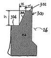
図6−図9bを参照すると、本発明のさらなる態様において、突出部300は、本体10の基端部から先端方向に延びるように形成されている。上記で示されたように、皮膚係合面52は、種々の形状をもつように形成され得る。ここでは、皮膚係合面52は、突出部の自由基端部302に形成されている。第1の表面部分304も、本体10の基端部30に形成されている。第1の表面部分304は、平坦で環状であり、突出部300を取り囲むことが好ましい。突出部300は、環状であり、チャネル26を取り囲むことが好ましい。突出部300は、チャネル26、特に第1の部分126と界接することがより好ましい。皮膚係合面52が突出部300に形成されている場合、取り囲む第1の表面部分302が、注射のあいだの安定性のための、より幅広い基部を与える。 Referring to FIGS. 6 to 9b, in a further aspect of the present invention, the
突出部300は、種々の断面形状をもつように形成され得る。最も好ましい実施形態においては、図8を参照すると、突出部は、矩形断面、特に正方形断面をもつように形成されている。高さhは、0.2mmから0.5mmまでの範囲内とすることができ、自由基端部302、従って皮膚係合面52の幅wは、0.2mmから0.5mmまでの範囲内とすることができる。もちろん、正方形断面の場合は、高さhおよび幅wがほぼ等しい。 The
他の断面形状が、突出部300について可能である。図9aを参照すると、突出部300は、0.5mmから1.0mmまでの範囲内の高さhと、0.35mmから0.6mmまでの範囲内の自由基端部302の幅wと、第1の表面部分304に対して30〜45度の範囲内の角度αをなすように配置された側面306とをもつ台形断面を有することができる。他の多角形形状も可能である。また、突出部302の一部は、図9bに示すように、弧状に形成されてもよい。 Other cross-sectional shapes are possible for the
上記で示されたように、突出部300がチャネル26と界接することが好ましい。本体10がガラスで形成されている場合、当業者であれば認識するように、皮膚係合面52と図1−図5の実施形態において示されたチャネル26との間の遷移部は、達成するのが難しい。特に、チャネル26を形成するのに使用されたピンまたは他の要素が、遷移部を容易に崩壊させ、形成の一貫性を達成するのが難しい。ガラスの本体10を形成する場合、突出部300が、チャネル26および周囲部分のより容易且つより均一な形成を可能にすることが見出された。突出部300(リング)は、ガラス形成プロセスのあいだに先端部とチャネルとの間に通常形成される半径を補償するために付加される。この結果がより急なコーナーである。 As indicated above, it is preferred that the
本発明は、幾つかの例を用いて好ましい実施形態に関して説明されてきたが、当業者であれば、添付の特許請求の範囲において定義される本発明の精神および範囲から逸脱することなく種々の修正を加えることができることを理解するであろう。 While the invention has been described in terms of preferred embodiments by way of examples, those skilled in the art will recognize that various modifications can be made without departing from the spirit and scope of the invention as defined in the appended claims. It will be understood that modifications can be made.
Claims (86)
Translated fromJapanese開放末端部および皮膚係合面が規定された基端部と、薬剤物質を収容するために前記末端部および前記基端部間に規定されたリザーバと、前記基端部に規定され、且つ、前記皮膚係合面を貫通して、そこから前記リザーバまで末端方向に延びるチャネルと、を有するユニット本体と、
鋭利にされた基端部および末端部を有する針カニューレと、
を備え、前記針カニューレは、前記末端部が前記リザーバと連通しており、前記針カニューレの前記基端部が約0.5mmから約3.0mmまでの範囲内の長さ、前記皮膚係合面から延びて、前記皮膚係合面が患者の皮膚の真皮層への前記針カニューレの前記基端部の貫入を制限するようになった状態で、前記チャネルに固定されていることを特徴とする皮内注射装置。An intradermal injection device,
A proximal end defined with an open distal end and a skin engaging surface; a reservoir defined between the distal end and the proximal end for containing a drug substance; defined at the proximal end; and A unit body having a channel extending through the skin engaging surface and extending distally therefrom to the reservoir;
A needle cannula having a sharpened proximal and distal ends;
The needle cannula has a distal end communicating with the reservoir, and the proximal end of the needle cannula has a length in the range of about 0.5 mm to about 3.0 mm, the skin engagement Extending from a surface, wherein the skin engaging surface is secured to the channel in a manner that limits the penetration of the proximal end of the needle cannula into the dermis layer of the patient's skin. Intradermal injection device.
開放末端部および第1の表面部分とそこから延びる突出部とを有する基端部と、薬剤物質を収容するために前記末端部および前記基端部間に規定されたリザーバと、前記ユニット本体の前記基端部に規定され、且つ、前記基端を貫通して、そこから末端方向に延びるチャネルと、を有するユニット本体と
鋭利にされた基端部および末端部を有する針カニューレと、
を備え、前記針カニューレは、前記末端部が前記リザーバと連通しており、前記針カニューレの前記基端部が約0.5mmから約3.0mmまでの範囲内の長さ、前記突出部から延びて、前記突出部が患者の皮膚の真皮層への前記針カニューレの前記基端部の貫入を制限するようになった状態で、前記チャネルに固定されていることを特徴とする皮内注射装置。An intradermal injection device,
A proximal end having an open distal end and a first surface portion and a protrusion extending therefrom; a reservoir defined between the distal end and the proximal end for receiving a drug substance; and A unit body defined by the proximal end and extending through and distally from the proximal end; and a needle cannula having a sharpened proximal end and a distal end;
The needle cannula is in communication with the reservoir at the distal end, and the proximal end of the needle cannula has a length in the range of about 0.5 mm to about 3.0 mm from the protrusion. Intradermal injection extending and secured to the channel with the protrusion limiting the penetration of the proximal end of the needle cannula into the dermal layer of the patient's skin apparatus.
56. The holder of claim 55, wherein the skin engaging surface defines a plane disposed substantially perpendicular to the longitudinal axis of the channel.
Applications Claiming Priority (3)
| Application Number | Priority Date | Filing Date | Title |
|---|---|---|---|
| US49850803P | 2003-08-28 | 2003-08-28 | |
| US60/498,508 | 2003-08-28 | ||
| PCT/US2004/002783WO2005025641A2 (en) | 2003-08-28 | 2004-01-30 | Intradermal injection device |
Publications (3)
| Publication Number | Publication Date |
|---|---|
| JP2007503866Atrue JP2007503866A (en) | 2007-03-01 |
| JP2007503866A5 JP2007503866A5 (en) | 2007-04-12 |
| JP4746545B2 JP4746545B2 (en) | 2011-08-10 |
Family
ID=34312171
Family Applications (1)
| Application Number | Title | Priority Date | Filing Date |
|---|---|---|---|
| JP2006524607AExpired - LifetimeJP4746545B2 (en) | 2003-08-28 | 2004-01-30 | Intradermal injection device |
Country Status (10)
| Country | Link |
|---|---|
| US (2) | US20070185460A1 (en) |
| EP (2) | EP1660149B1 (en) |
| JP (1) | JP4746545B2 (en) |
| CN (1) | CN100509072C (en) |
| AU (1) | AU2004271893B2 (en) |
| BR (1) | BRPI0414021B1 (en) |
| CA (1) | CA2536681C (en) |
| MX (1) | MXPA06002047A (en) |
| WO (1) | WO2005025641A2 (en) |
| ZA (1) | ZA200602318B (en) |
Cited By (4)
| Publication number | Priority date | Publication date | Assignee | Title |
|---|---|---|---|---|
| JP2009090098A (en)* | 2007-09-07 | 2009-04-30 | Becton Dickinson & Co | Pen needle hub with increased contact area |
| WO2012098767A1 (en)* | 2011-01-19 | 2012-07-26 | テルモ株式会社 | Syringe provided with needle and method for producing syringe provided with needle |
| WO2012098766A1 (en)* | 2011-01-19 | 2012-07-26 | テルモ株式会社 | Syringe provided with needle, and method for producing syringe provided with needle |
| JP2018061856A (en)* | 2010-09-29 | 2018-04-19 | テルモ株式会社 | Syringe with needle and manufacturing method of syringe with needle |
Families Citing this family (23)
| Publication number | Priority date | Publication date | Assignee | Title |
|---|---|---|---|---|
| CN100349629C (en) | 2001-09-12 | 2007-11-21 | 贝克顿迪肯森公司 | Microneedle-based pen device for drug delivery and method of using same |
| US9486581B2 (en) | 2002-09-11 | 2016-11-08 | Becton, Dickinson And Company | Injector device with force lock-out and injection rate limiting mechanisms |
| US7645264B2 (en) | 2005-04-11 | 2010-01-12 | Becton, Dickinson And Company | Injection device with secondary reservoir |
| US7842008B2 (en) | 2005-11-21 | 2010-11-30 | Becton, Dickinson And Company | Intradermal delivery device |
| CN102716532A (en)* | 2008-01-15 | 2012-10-10 | 西部制药服务公司 | Collet mechanism and method of molding cannula to a syringe barrel |
| US8721603B2 (en) | 2008-01-15 | 2014-05-13 | West Pharmaceutical Services, Inc. | Syringe with co-molded hub and cannula |
| CA2951841C (en) | 2008-07-18 | 2018-07-10 | Becton, Dickinson And Company | Dual chamber and gear pump assembly for a high pressure delivery system |
| MY169699A (en)* | 2008-09-30 | 2019-05-13 | Terumo Corp | Injection needle and drug injection device |
| EP2403572B1 (en) | 2009-03-03 | 2019-01-16 | Becton, Dickinson and Company | Pen needle assembly for delivering drug solutions |
| US20110224606A1 (en)* | 2010-03-10 | 2011-09-15 | Shibaji Shome | Method and apparatus for remote ischemic conditioning during revascularization |
| US9962500B2 (en) | 2011-04-28 | 2018-05-08 | Sanofi-Aventis Deutschland Gmbh | Connection for medical device |
| CN103501846B (en)* | 2011-04-28 | 2016-02-10 | 泰尔茂株式会社 | Entry needle assembly and medication injection device |
| USD693002S1 (en) | 2011-09-21 | 2013-11-05 | West Pharmaceutical Services, Inc. | Hub for medical container |
| EP2572741A1 (en)* | 2011-09-23 | 2013-03-27 | Sanofi-Aventis Deutschland GmbH | Medicament delivery device and actuation mechanism for a drug delivery device |
| DE102012202693A1 (en)* | 2012-02-22 | 2013-08-22 | Transcodent GmbH & Co. KG | Dispensing container for dental material |
| CN204395138U (en) | 2012-04-09 | 2015-06-17 | 贝克顿·迪金森公司 | For the induction system of point medicine |
| USD689188S1 (en) | 2012-07-19 | 2013-09-03 | West Pharmaceutical Services, Inc. | Syringe plunger rod |
| JP6625566B2 (en)* | 2015-01-20 | 2019-12-25 | テルモ株式会社 | Injection needle assembly and syringe for injecting a drug solution into the upper layer of skin having the same |
| WO2017058755A1 (en) | 2015-09-28 | 2017-04-06 | Tuttlenumbnow Llc | Systems and methods for bending a needle |
| WO2017177086A1 (en)* | 2016-04-08 | 2017-10-12 | Becton, Dickinson And Company | Syringe with a patient contact surface |
| DE102019108583B4 (en)* | 2019-04-02 | 2023-02-09 | Gerresheimer Regensburg Gmbh | Method of connecting a first component to a second component |
| KR20220039752A (en)* | 2019-08-02 | 2022-03-29 | 노드슨 코포레이션 | Dispensing tip and method of making the same |
| US20210323022A1 (en)* | 2020-04-20 | 2021-10-21 | Asm Technology Singapore Pte Ltd | Fluid-dispensing apparatus |
Citations (3)
| Publication number | Priority date | Publication date | Assignee | Title |
|---|---|---|---|---|
| JP2002291884A (en)* | 2001-01-25 | 2002-10-08 | Terumo Corp | Liquid injection needle and liquid injecting unit |
| WO2002083215A1 (en)* | 2001-04-13 | 2002-10-24 | Becton Dickinson And Company | Intradermal needle |
| WO2003022330A2 (en)* | 2001-09-12 | 2003-03-20 | Becton, Dickinson And Company | Microneedle-based pen device for drug delivery and method for using same |
Family Cites Families (99)
| Publication number | Priority date | Publication date | Assignee | Title |
|---|---|---|---|---|
| DE46325C (en) | B. SlMSKY in Königsberg i. Pr., Steindamm 83 | Innovation in syringes for subcutaneous injection | ||
| DE596981C (en) | 1931-10-30 | 1934-05-12 | Mario Demarchi Dr | Injection syringe |
| US2588623A (en) | 1948-05-10 | 1952-03-11 | Eliscu Frank | Surgical instrument for intradermal injection of fluids |
| DE958766C (en) | 1953-06-08 | 1957-02-21 | Becton Dickinson Co | Injection syringe |
| US2876770A (en) | 1955-10-10 | 1959-03-10 | Raymond A White | Shielded hypodermic syringe |
| DE1166419B (en) | 1958-09-03 | 1964-03-26 | Dr Fritz Linder | Injection syringe |
| US3430627A (en)* | 1963-06-10 | 1969-03-04 | Owens Illinois Inc | Hypodermic needle |
| US3400715A (en) | 1966-01-04 | 1968-09-10 | Halvard J. Pederson | Attachment for injection apparatus |
| US3688764A (en) | 1970-08-20 | 1972-09-05 | Bard Hamilton Co Inc | Intracutaneous injection system |
| US3797490A (en) | 1971-02-11 | 1974-03-19 | Ampoules Inc | Hypodermic ampoule with skin tensioning clip |
| US4014797A (en)* | 1973-12-11 | 1977-03-29 | Burron Medical Products, Inc. | Intravenous injection apparatus and needle adapter with filter and method of making same |
| US4040421A (en)* | 1975-04-04 | 1977-08-09 | Becton, Dickinson And Company | Hypodermic syringe and attached needle assembly |
| US4304241A (en) | 1978-09-05 | 1981-12-08 | Aller-Screen, Inc. | Skin testing device |
| DE2929425A1 (en) | 1979-07-20 | 1981-02-12 | Lothar Kling | DEVICE FOR INJECTION SYRINGES FOR INTRAMUSCULAR AND SUBENTANE INJECTION |
| US4270537A (en) | 1979-11-19 | 1981-06-02 | Romaine Richard A | Automatic hypodermic syringe |
| JPS5695058A (en) | 1979-12-10 | 1981-08-01 | Toyo Jozo Kk | Microosyringe |
| JPS5825171A (en)* | 1981-08-06 | 1983-02-15 | テルモ株式会社 | Syringe |
| FR2524321A1 (en) | 1982-03-30 | 1983-10-07 | Denance Raymond | "MANUAL OR MECHANICAL" INJECTION DEVICE FOR MEDICAL AND VETERINARY USE |
| US4774948A (en) | 1986-11-24 | 1988-10-04 | Markham Charles W | Marking and retraction needle having retrievable stylet |
| DE3642164A1 (en) | 1986-12-10 | 1988-06-23 | Basf Ag | METHOD FOR REMOVING ACID FROM CATHODIC ELECTRO-DIP LACQUER BATHS BY ELECTRODIALYSIS |
| CA1283827C (en) | 1986-12-18 | 1991-05-07 | Giorgio Cirelli | Appliance for injection of liquid formulations |
| FR2612401A1 (en) | 1987-03-16 | 1988-09-23 | Denance Raymond | Stabiliser end-piece for hypodermic needle comprising a means acting as a prop for regulating the penetration as a function of attack of the needle in the skin |
| US4795445A (en)* | 1987-03-27 | 1989-01-03 | Becton, Dickinson And Company | Hub configuration |
| US4955871A (en) | 1987-04-29 | 1990-09-11 | Path | Single-use disposable syringe |
| US4769003A (en) | 1987-08-19 | 1988-09-06 | Keith Stamler | Wound irrigation splashback shield |
| US5195526A (en) | 1988-03-11 | 1993-03-23 | Michelson Gary K | Spinal marker needle |
| US4834704A (en) | 1988-04-13 | 1989-05-30 | Eaton Corporation | Injectable infusion pump apparatus for implanting long-term dispensing module and medication in an animal and method therefor |
| US4978344A (en) | 1988-08-11 | 1990-12-18 | Dombrowski Mitchell P | Needle and catheter assembly |
| US4898588A (en) | 1988-10-17 | 1990-02-06 | Roberts Christopher W | Hypodermic syringe splatter shield |
| FR2638359A1 (en) | 1988-11-03 | 1990-05-04 | Tino Dalto | SYRINGE GUIDE WITH ADJUSTMENT OF DEPTH DEPTH OF NEEDLE IN SKIN |
| IE65903B1 (en) | 1989-06-02 | 1995-11-29 | Becton Dickinson Co | Syringe assembly |
| GB8926825D0 (en) | 1989-11-28 | 1990-01-17 | Glaxo Group Ltd | Device |
| US5505694A (en) | 1990-08-22 | 1996-04-09 | Tcnl Technologies, Inc. | Apparatus and method for raising a skin wheal |
| US5190521A (en) | 1990-08-22 | 1993-03-02 | Tecnol Medical Products, Inc. | Apparatus and method for raising a skin wheal and anesthetizing skin |
| US5527288A (en) | 1990-12-13 | 1996-06-18 | Elan Medical Technologies Limited | Intradermal drug delivery device and method for intradermal delivery of drugs |
| TW279133B (en) | 1990-12-13 | 1996-06-21 | Elan Med Tech | |
| US5222949A (en) | 1991-07-23 | 1993-06-29 | Intermed, Inc. | Flexible, noncollapsible catheter tube with hard and soft regions |
| GB9116595D0 (en) | 1991-08-01 | 1991-09-18 | Univ London | Improvements in or relating to syringes |
| SE9102652D0 (en) | 1991-09-13 | 1991-09-13 | Kabi Pharmacia Ab | INJECTION NEEDLE ARRANGEMENT |
| NZ244980A (en) | 1991-11-15 | 1994-07-26 | Delta West Pty Ltd | Injection device operated by a deformable plastics ampoule |
| US5328483A (en) | 1992-02-27 | 1994-07-12 | Jacoby Richard M | Intradermal injection device with medication and needle guard |
| GB9207731D0 (en) | 1992-04-07 | 1992-05-27 | Proteus Molecular Design | Improvements in or relating to vaccines |
| IL101720A (en) | 1992-04-29 | 1998-09-24 | Mali Tech Ltd | Needle for syringe or the like |
| US5267963A (en) | 1992-08-21 | 1993-12-07 | Nicholas Bachynsky | Medication injection device |
| IT1256577B (en) | 1992-12-11 | 1995-12-11 | Ermanno Greco | DEVICE PREPARED FOR THE AUTOMATIC ADMINISTRATION OF A DRUG VIA INTRADERMIC. |
| IE68890B1 (en) | 1993-04-08 | 1996-07-24 | Elan Med Tech | Intradermal delivery device |
| WO1995001198A1 (en) | 1993-07-02 | 1995-01-12 | Ji Hoon Park | Syringe |
| US5997501A (en) | 1993-11-18 | 1999-12-07 | Elan Corporation, Plc | Intradermal drug delivery device |
| US5519931A (en) | 1994-03-16 | 1996-05-28 | Syncor International Corporation | Container and method for transporting a syringe containing radioactive material |
| DE4438360C2 (en)* | 1994-10-27 | 1999-05-20 | Schott Glas | Pre-fillable, low-particle, sterile disposable syringe for the injection of preparations and methods for their manufacture |
| JP3208525B2 (en)* | 1995-01-05 | 2001-09-17 | 電気化学工業株式会社 | Sodium hyaluronate solution injection and container for injection |
| GB9504216D0 (en)* | 1995-03-02 | 1995-04-19 | Magstim Co Ltd | Magnetic stimulator for neuro-muscular tissue |
| FR2733687B1 (en)* | 1995-05-04 | 1997-10-03 | Brunel Marc | METHOD FOR MANUFACTURING A PRE-FILLED INJECTION DEVICE CONTAINING A DOSE OF LIQUID TO BE INJECTED, AND INJECTION DEVICE PRODUCED |
| US6210361B1 (en) | 1997-08-22 | 2001-04-03 | Deka Products Limited Partnership | System for delivering intravenous drugs |
| SE9502285D0 (en) | 1995-06-22 | 1995-06-22 | Pharmacia Ab | Improvements related to injections |
| JPH09163244A (en) | 1995-12-05 | 1997-06-20 | Olympus Optical Co Ltd | Solid-state image pickup device |
| ZA9610374B (en) | 1995-12-11 | 1997-06-23 | Elan Med Tech | Cartridge-based drug delivery device |
| US5776124A (en)* | 1996-07-15 | 1998-07-07 | Wald; Arnold | Reusable adapter for uniting a syringe and vial |
| US6146361A (en) | 1996-09-26 | 2000-11-14 | Becton Dickinson And Company | Medication delivery pen having a 31 gauge needle |
| US5833668A (en) | 1996-11-21 | 1998-11-10 | Aguilar; David G. | Hypodermic syringe |
| GB2321014A (en) | 1997-01-14 | 1998-07-15 | Nigel John Middleton | Hypodermic needle with retractable needle guard |
| IE970782A1 (en) | 1997-10-22 | 1999-05-05 | Elan Corp | An improved automatic syringe |
| DE29820166U1 (en) | 1997-11-19 | 1999-03-25 | Medico Development Investment Co., Ascona | Needle assembly for an injection device |
| US6482176B1 (en) | 1997-11-27 | 2002-11-19 | Disetronic Licensing Ag | Method and device for controlling the introduction depth of an injection needle |
| IT1298087B1 (en) | 1998-01-08 | 1999-12-20 | Fiderm S R L | DEVICE FOR CHECKING THE PENETRATION DEPTH OF A NEEDLE, IN PARTICULAR APPLICABLE TO A SYRINGE FOR INJECTIONS |
| US6616639B2 (en)* | 1998-04-17 | 2003-09-09 | Becton, Dickinson And Company | Safety shield system for syringes |
| JP4118399B2 (en) | 1998-07-21 | 2008-07-16 | テルモ株式会社 | Puncture adjusting tool for injection needle and injection needle assembly including the same |
| US6428528B2 (en) | 1998-08-11 | 2002-08-06 | Antares Pharma, Inc. | Needle assisted jet injector |
| US6319224B1 (en) | 1999-08-20 | 2001-11-20 | Bioject Medical Technologies Inc. | Intradermal injection system for injecting DNA-based injectables into humans |
| US6569143B2 (en) | 1999-10-14 | 2003-05-27 | Becton, Dickinson And Company | Method of intradermally injecting substances |
| US7241275B2 (en) | 1999-10-14 | 2007-07-10 | Becton, Dickinson And Company | Intradermal needle |
| US20020095134A1 (en) | 1999-10-14 | 2002-07-18 | Pettis Ronald J. | Method for altering drug pharmacokinetics based on medical delivery platform |
| US20020193740A1 (en)* | 1999-10-14 | 2002-12-19 | Alchas Paul G. | Method of intradermally injecting substances |
| US6494865B1 (en) | 1999-10-14 | 2002-12-17 | Becton Dickinson And Company | Intradermal delivery device including a needle assembly |
| US6843781B2 (en) | 1999-10-14 | 2005-01-18 | Becton, Dickinson And Company | Intradermal needle |
| DE19950530A1 (en)* | 1999-10-20 | 2001-06-13 | Frank Neveling | Syringe for intracutaneous injection |
| DE29918794U1 (en) | 1999-10-26 | 1999-12-30 | Dieter Hölzle Technik-Projekte GmbH, 75392 Deckenpfronn | Carpule for taking a medicine |
| US6599269B1 (en)* | 1999-12-03 | 2003-07-29 | Becton Dickinson And Company | Single-use syringe |
| DE60005998T2 (en)* | 1999-12-23 | 2004-11-11 | Tecpharma Licensing Ag | INJECTION DEVICE AND DRIVE SYSTEM THEREFOR |
| WO2001070312A1 (en)* | 2000-03-22 | 2001-09-27 | Nipro Corporation | Medical syringe needle |
| JP2001295618A (en) | 2000-04-18 | 2001-10-26 | Yamaha Motor Co Ltd | Oil pump arrangement structure for internal combustion engine |
| US6537242B1 (en) | 2000-06-06 | 2003-03-25 | Becton, Dickinson And Company | Method and apparatus for enhancing penetration of a member for the intradermal sampling or administration of a substance |
| US6986760B2 (en) | 2000-08-02 | 2006-01-17 | Becton, Dickinson And Company | Pen needle and safety shield system |
| JP4187922B2 (en)* | 2000-09-14 | 2008-11-26 | テルモ株式会社 | Liquid injection needle and liquid injection device |
| US6595960B2 (en)* | 2001-04-12 | 2003-07-22 | Becton, Dickinson And Company | Flexible needle assembly |
| US6689100B2 (en) | 2001-10-05 | 2004-02-10 | Becton, Dickinson And Company | Microdevice and method of delivering or withdrawing a substance through the skin of an animal |
| WO2003041763A2 (en)* | 2001-11-14 | 2003-05-22 | Medical Instill Technologies, Inc. | Intradermal delivery device and method |
| EP2111885B1 (en) | 2002-02-04 | 2011-09-21 | Becton, Dickinson and Company | Device and method for delivering or withdrawing a substance through the skin |
| US20070005017A1 (en)* | 2002-02-04 | 2007-01-04 | Becton, Dickinson And Company | Intradermal delivery device with crenellated skin engaging surface geometry |
| WO2003068290A2 (en)* | 2002-02-11 | 2003-08-21 | Antares Pharma, Inc. | Intradermal injector |
| US20030212379A1 (en)* | 2002-02-26 | 2003-11-13 | Bylund Adam David | Systems and methods for remotely controlling medication infusion and analyte monitoring |
| US6780171B2 (en) | 2002-04-02 | 2004-08-24 | Becton, Dickinson And Company | Intradermal delivery device |
| JP4613158B2 (en)* | 2003-01-30 | 2011-01-12 | ベクトン・ディキンソン・アンド・カンパニー | Intradermal delivery device formed with skin engaging surface shape |
| US20050256499A1 (en) | 2004-03-03 | 2005-11-17 | Pettis Ronald J | Methods and devices for improving delivery of a substance to skin |
| US7645264B2 (en)* | 2005-04-11 | 2010-01-12 | Becton, Dickinson And Company | Injection device with secondary reservoir |
| US8496628B2 (en)* | 2005-09-30 | 2013-07-30 | Erskine Medical Llc | Needle-based medical device including needle guide |
| CN102716532A (en)* | 2008-01-15 | 2012-10-10 | 西部制药服务公司 | Collet mechanism and method of molding cannula to a syringe barrel |
| US8721603B2 (en)* | 2008-01-15 | 2014-05-13 | West Pharmaceutical Services, Inc. | Syringe with co-molded hub and cannula |
| CN103096953B (en)* | 2010-09-29 | 2016-03-16 | 泰尔茂株式会社 | Band needle injection |
- 2004
- 2004-01-30EPEP04707062.8Apatent/EP1660149B1/ennot_activeExpired - Lifetime
- 2004-01-30CNCNB2004800286075Apatent/CN100509072C/ennot_activeExpired - Lifetime
- 2004-01-30MXMXPA06002047Apatent/MXPA06002047A/enactiveIP Right Grant
- 2004-01-30JPJP2006524607Apatent/JP4746545B2/ennot_activeExpired - Lifetime
- 2004-01-30WOPCT/US2004/002783patent/WO2005025641A2/enactiveApplication Filing
- 2004-01-30CACA2536681Apatent/CA2536681C/ennot_activeExpired - Lifetime
- 2004-01-30AUAU2004271893Apatent/AU2004271893B2/ennot_activeExpired
- 2004-01-30EPEP18160170.9Apatent/EP3354308B1/ennot_activeExpired - Lifetime
- 2004-01-30USUS10/569,618patent/US20070185460A1/ennot_activeAbandoned
- 2004-01-30BRBRPI0414021-4Apatent/BRPI0414021B1/ennot_activeIP Right Cessation
- 2006
- 2006-03-20ZAZA200602318Apatent/ZA200602318B/enunknown
- 2014
- 2014-12-12USUS14/568,526patent/US9682198B2/ennot_activeExpired - Fee Related
Patent Citations (3)
| Publication number | Priority date | Publication date | Assignee | Title |
|---|---|---|---|---|
| JP2002291884A (en)* | 2001-01-25 | 2002-10-08 | Terumo Corp | Liquid injection needle and liquid injecting unit |
| WO2002083215A1 (en)* | 2001-04-13 | 2002-10-24 | Becton Dickinson And Company | Intradermal needle |
| WO2003022330A2 (en)* | 2001-09-12 | 2003-03-20 | Becton, Dickinson And Company | Microneedle-based pen device for drug delivery and method for using same |
Cited By (9)
| Publication number | Priority date | Publication date | Assignee | Title |
|---|---|---|---|---|
| JP2009090098A (en)* | 2007-09-07 | 2009-04-30 | Becton Dickinson & Co | Pen needle hub with increased contact area |
| US9125997B2 (en) | 2007-09-07 | 2015-09-08 | Becton, Dickinson And Company | Pen needle hub having increased contact area |
| US9604013B2 (en) | 2007-09-07 | 2017-03-28 | Becton, Dickinson And Company | Pen needle hub having increased contact area |
| US10201669B2 (en) | 2007-09-07 | 2019-02-12 | Becton, Dickinson And Company | Pen needle hub having increased contact area |
| US10926044B2 (en) | 2007-09-07 | 2021-02-23 | Becton, Dickinson And Company | Pen needle hub having increased contact area |
| JP2018061856A (en)* | 2010-09-29 | 2018-04-19 | テルモ株式会社 | Syringe with needle and manufacturing method of syringe with needle |
| US10384379B2 (en) | 2010-09-29 | 2019-08-20 | Terumo Kabushiki Kaisha | Syringe with needle |
| WO2012098767A1 (en)* | 2011-01-19 | 2012-07-26 | テルモ株式会社 | Syringe provided with needle and method for producing syringe provided with needle |
| WO2012098766A1 (en)* | 2011-01-19 | 2012-07-26 | テルモ株式会社 | Syringe provided with needle, and method for producing syringe provided with needle |
Also Published As
| Publication number | Publication date |
|---|---|
| BRPI0414021A (en) | 2006-10-24 |
| CN1859937A (en) | 2006-11-08 |
| CN100509072C (en) | 2009-07-08 |
| US20150100022A1 (en) | 2015-04-09 |
| US20070185460A1 (en) | 2007-08-09 |
| BRPI0414021B1 (en) | 2023-09-26 |
| EP1660149B1 (en) | 2018-03-07 |
| WO2005025641A3 (en) | 2006-04-13 |
| AU2004271893B2 (en) | 2010-07-29 |
| MXPA06002047A (en) | 2006-05-25 |
| US9682198B2 (en) | 2017-06-20 |
| JP4746545B2 (en) | 2011-08-10 |
| WO2005025641A2 (en) | 2005-03-24 |
| EP3354308A1 (en) | 2018-08-01 |
| CA2536681C (en) | 2011-07-05 |
| EP1660149A4 (en) | 2009-01-14 |
| EP1660149A2 (en) | 2006-05-31 |
| EP3354308B1 (en) | 2020-11-11 |
| ZA200602318B (en) | 2007-09-26 |
| CA2536681A1 (en) | 2005-03-24 |
| AU2004271893A1 (en) | 2005-03-24 |
Similar Documents
| Publication | Publication Date | Title |
|---|---|---|
| JP4746545B2 (en) | Intradermal injection device | |
| CN100551455C (en) | Intradermal syringe and needle assembly | |
| JP4751009B2 (en) | Prefillable intradermal delivery device with concealed needle and passive shield | |
| EP1289587B1 (en) | A disposable double pointed injection needle | |
| US9095660B2 (en) | Disposable double point injection needle and an insulin injection system comprising a disposable double point injection needle | |
| US9089655B2 (en) | Intradermal injection adapter | |
| AU2002354520B2 (en) | Syringe and needle for preventing inadvertent drug injection | |
| US9055992B2 (en) | Dual medicament carpule for dental syringes | |
| CN102369034A (en) | Syringe needle assembly and medicament injection device | |
| KR20140034900A (en) | Injection apparatus with needle housing for desensitising skin |
Legal Events
| Date | Code | Title | Description |
|---|---|---|---|
| A521 | Request for written amendment filed | Free format text:JAPANESE INTERMEDIATE CODE: A523 Effective date:20070125 | |
| A621 | Written request for application examination | Free format text:JAPANESE INTERMEDIATE CODE: A621 Effective date:20070125 | |
| A131 | Notification of reasons for refusal | Free format text:JAPANESE INTERMEDIATE CODE: A131 Effective date:20090807 | |
| A601 | Written request for extension of time | Free format text:JAPANESE INTERMEDIATE CODE: A601 Effective date:20091106 | |
| A602 | Written permission of extension of time | Free format text:JAPANESE INTERMEDIATE CODE: A602 Effective date:20091113 | |
| A601 | Written request for extension of time | Free format text:JAPANESE INTERMEDIATE CODE: A601 Effective date:20091207 | |
| A602 | Written permission of extension of time | Free format text:JAPANESE INTERMEDIATE CODE: A602 Effective date:20091214 | |
| A601 | Written request for extension of time | Free format text:JAPANESE INTERMEDIATE CODE: A601 Effective date:20100106 | |
| A602 | Written permission of extension of time | Free format text:JAPANESE INTERMEDIATE CODE: A602 Effective date:20100114 | |
| A521 | Request for written amendment filed | Free format text:JAPANESE INTERMEDIATE CODE: A523 Effective date:20100208 | |
| A131 | Notification of reasons for refusal | Free format text:JAPANESE INTERMEDIATE CODE: A131 Effective date:20100709 | |
| A601 | Written request for extension of time | Free format text:JAPANESE INTERMEDIATE CODE: A601 Effective date:20101012 | |
| A602 | Written permission of extension of time | Free format text:JAPANESE INTERMEDIATE CODE: A602 Effective date:20101019 | |
| A521 | Request for written amendment filed | Free format text:JAPANESE INTERMEDIATE CODE: A523 Effective date:20101109 | |
| TRDD | Decision of grant or rejection written | ||
| A01 | Written decision to grant a patent or to grant a registration (utility model) | Free format text:JAPANESE INTERMEDIATE CODE: A01 Effective date:20110428 | |
| A01 | Written decision to grant a patent or to grant a registration (utility model) | Free format text:JAPANESE INTERMEDIATE CODE: A01 | |
| A61 | First payment of annual fees (during grant procedure) | Free format text:JAPANESE INTERMEDIATE CODE: A61 Effective date:20110513 | |
| FPAY | Renewal fee payment (event date is renewal date of database) | Free format text:PAYMENT UNTIL: 20140520 Year of fee payment:3 | |
| R150 | Certificate of patent or registration of utility model | Ref document number:4746545 Country of ref document:JP Free format text:JAPANESE INTERMEDIATE CODE: R150 | |
| R250 | Receipt of annual fees | Free format text:JAPANESE INTERMEDIATE CODE: R250 | |
| R250 | Receipt of annual fees | Free format text:JAPANESE INTERMEDIATE CODE: R250 | |
| R250 | Receipt of annual fees | Free format text:JAPANESE INTERMEDIATE CODE: R250 | |
| R250 | Receipt of annual fees | Free format text:JAPANESE INTERMEDIATE CODE: R250 | |
| R250 | Receipt of annual fees | Free format text:JAPANESE INTERMEDIATE CODE: R250 | |
| R250 | Receipt of annual fees | Free format text:JAPANESE INTERMEDIATE CODE: R250 | |
| R250 | Receipt of annual fees | Free format text:JAPANESE INTERMEDIATE CODE: R250 | |
| R250 | Receipt of annual fees | Free format text:JAPANESE INTERMEDIATE CODE: R250 | |
| R250 | Receipt of annual fees | Free format text:JAPANESE INTERMEDIATE CODE: R250 | |
| EXPY | Cancellation because of completion of term |