JP2007503603A - Display device and viewing angle control unit used therefor - Google Patents
Display device and viewing angle control unit used thereforDownload PDFInfo
- Publication number
- JP2007503603A JP2007503603AJP2006523736AJP2006523736AJP2007503603AJP 2007503603 AJP2007503603 AJP 2007503603AJP 2006523736 AJP2006523736 AJP 2006523736AJP 2006523736 AJP2006523736 AJP 2006523736AJP 2007503603 AJP2007503603 AJP 2007503603A
- Authority
- JP
- Japan
- Prior art keywords
- display device
- viewing angle
- control unit
- angle control
- pair
- Prior art date
- Legal status (The legal status is an assumption and is not a legal conclusion. Google has not performed a legal analysis and makes no representation as to the accuracy of the status listed.)
- Pending
Links
- 239000004973liquid crystal related substanceSubstances0.000claimsabstractdescription69
- 230000003287optical effectEffects0.000claimsabstractdescription33
- 239000000758substrateSubstances0.000claimsdescription23
- 238000010521absorption reactionMethods0.000claimsdescription7
- 230000005540biological transmissionEffects0.000claimsdescription7
- 238000005401electroluminescenceMethods0.000claimsdescription3
- 229910010272inorganic materialInorganic materials0.000description4
- 239000011147inorganic materialSubstances0.000description4
- 229920006254polymer filmPolymers0.000description4
- 239000000463materialSubstances0.000description3
- 230000003247decreasing effectEffects0.000description2
- 238000010586diagramMethods0.000description2
- 230000005684electric fieldEffects0.000description2
- 238000012986modificationMethods0.000description2
- 230000004048modificationEffects0.000description2
- 238000000151depositionMethods0.000description1
- 230000000694effectsEffects0.000description1
- 239000011521glassSubstances0.000description1
- 239000002184metalSubstances0.000description1
- 229920003023plasticPolymers0.000description1
- 229920001721polyimidePolymers0.000description1
- 238000007740vapor depositionMethods0.000description1
Images


Classifications
- G—PHYSICS
- G02—OPTICS
- G02F—OPTICAL DEVICES OR ARRANGEMENTS FOR THE CONTROL OF LIGHT BY MODIFICATION OF THE OPTICAL PROPERTIES OF THE MEDIA OF THE ELEMENTS INVOLVED THEREIN; NON-LINEAR OPTICS; FREQUENCY-CHANGING OF LIGHT; OPTICAL LOGIC ELEMENTS; OPTICAL ANALOGUE/DIGITAL CONVERTERS
- G02F1/00—Devices or arrangements for the control of the intensity, colour, phase, polarisation or direction of light arriving from an independent light source, e.g. switching, gating or modulating; Non-linear optics
- G02F1/01—Devices or arrangements for the control of the intensity, colour, phase, polarisation or direction of light arriving from an independent light source, e.g. switching, gating or modulating; Non-linear optics for the control of the intensity, phase, polarisation or colour
- G02F1/13—Devices or arrangements for the control of the intensity, colour, phase, polarisation or direction of light arriving from an independent light source, e.g. switching, gating or modulating; Non-linear optics for the control of the intensity, phase, polarisation or colour based on liquid crystals, e.g. single liquid crystal display cells
- G02F1/1323—Arrangements for providing a switchable viewing angle
- G—PHYSICS
- G02—OPTICS
- G02F—OPTICAL DEVICES OR ARRANGEMENTS FOR THE CONTROL OF LIGHT BY MODIFICATION OF THE OPTICAL PROPERTIES OF THE MEDIA OF THE ELEMENTS INVOLVED THEREIN; NON-LINEAR OPTICS; FREQUENCY-CHANGING OF LIGHT; OPTICAL LOGIC ELEMENTS; OPTICAL ANALOGUE/DIGITAL CONVERTERS
- G02F1/00—Devices or arrangements for the control of the intensity, colour, phase, polarisation or direction of light arriving from an independent light source, e.g. switching, gating or modulating; Non-linear optics
- G02F1/01—Devices or arrangements for the control of the intensity, colour, phase, polarisation or direction of light arriving from an independent light source, e.g. switching, gating or modulating; Non-linear optics for the control of the intensity, phase, polarisation or colour
- G02F1/13—Devices or arrangements for the control of the intensity, colour, phase, polarisation or direction of light arriving from an independent light source, e.g. switching, gating or modulating; Non-linear optics for the control of the intensity, phase, polarisation or colour based on liquid crystals, e.g. single liquid crystal display cells
- G02F1/133—Constructional arrangements; Operation of liquid crystal cells; Circuit arrangements
- G02F1/1333—Constructional arrangements; Manufacturing methods
- G02F1/1335—Structural association of cells with optical devices, e.g. polarisers or reflectors
- G—PHYSICS
- G02—OPTICS
- G02F—OPTICAL DEVICES OR ARRANGEMENTS FOR THE CONTROL OF LIGHT BY MODIFICATION OF THE OPTICAL PROPERTIES OF THE MEDIA OF THE ELEMENTS INVOLVED THEREIN; NON-LINEAR OPTICS; FREQUENCY-CHANGING OF LIGHT; OPTICAL LOGIC ELEMENTS; OPTICAL ANALOGUE/DIGITAL CONVERTERS
- G02F1/00—Devices or arrangements for the control of the intensity, colour, phase, polarisation or direction of light arriving from an independent light source, e.g. switching, gating or modulating; Non-linear optics
- G02F1/01—Devices or arrangements for the control of the intensity, colour, phase, polarisation or direction of light arriving from an independent light source, e.g. switching, gating or modulating; Non-linear optics for the control of the intensity, phase, polarisation or colour
- G02F1/13—Devices or arrangements for the control of the intensity, colour, phase, polarisation or direction of light arriving from an independent light source, e.g. switching, gating or modulating; Non-linear optics for the control of the intensity, phase, polarisation or colour based on liquid crystals, e.g. single liquid crystal display cells
- G02F1/133—Constructional arrangements; Operation of liquid crystal cells; Circuit arrangements
- G02F1/1333—Constructional arrangements; Manufacturing methods
- G02F1/1347—Arrangement of liquid crystal layers or cells in which the final condition of one light beam is achieved by the addition of the effects of two or more layers or cells
- G02F1/13471—Arrangement of liquid crystal layers or cells in which the final condition of one light beam is achieved by the addition of the effects of two or more layers or cells in which all the liquid crystal cells or layers remain transparent, e.g. FLC, ECB, DAP, HAN, TN, STN, SBE-LC cells
- G—PHYSICS
- G02—OPTICS
- G02F—OPTICAL DEVICES OR ARRANGEMENTS FOR THE CONTROL OF LIGHT BY MODIFICATION OF THE OPTICAL PROPERTIES OF THE MEDIA OF THE ELEMENTS INVOLVED THEREIN; NON-LINEAR OPTICS; FREQUENCY-CHANGING OF LIGHT; OPTICAL LOGIC ELEMENTS; OPTICAL ANALOGUE/DIGITAL CONVERTERS
- G02F1/00—Devices or arrangements for the control of the intensity, colour, phase, polarisation or direction of light arriving from an independent light source, e.g. switching, gating or modulating; Non-linear optics
- G02F1/01—Devices or arrangements for the control of the intensity, colour, phase, polarisation or direction of light arriving from an independent light source, e.g. switching, gating or modulating; Non-linear optics for the control of the intensity, phase, polarisation or colour
- G02F1/13—Devices or arrangements for the control of the intensity, colour, phase, polarisation or direction of light arriving from an independent light source, e.g. switching, gating or modulating; Non-linear optics for the control of the intensity, phase, polarisation or colour based on liquid crystals, e.g. single liquid crystal display cells
- G02F1/137—Devices or arrangements for the control of the intensity, colour, phase, polarisation or direction of light arriving from an independent light source, e.g. switching, gating or modulating; Non-linear optics for the control of the intensity, phase, polarisation or colour based on liquid crystals, e.g. single liquid crystal display cells characterised by the electro-optical or magneto-optical effect, e.g. field-induced phase transition, orientation effect, guest-host interaction or dynamic scattering
- G02F1/139—Devices or arrangements for the control of the intensity, colour, phase, polarisation or direction of light arriving from an independent light source, e.g. switching, gating or modulating; Non-linear optics for the control of the intensity, phase, polarisation or colour based on liquid crystals, e.g. single liquid crystal display cells characterised by the electro-optical or magneto-optical effect, e.g. field-induced phase transition, orientation effect, guest-host interaction or dynamic scattering based on orientation effects in which the liquid crystal remains transparent
- G02F1/1393—Devices or arrangements for the control of the intensity, colour, phase, polarisation or direction of light arriving from an independent light source, e.g. switching, gating or modulating; Non-linear optics for the control of the intensity, phase, polarisation or colour based on liquid crystals, e.g. single liquid crystal display cells characterised by the electro-optical or magneto-optical effect, e.g. field-induced phase transition, orientation effect, guest-host interaction or dynamic scattering based on orientation effects in which the liquid crystal remains transparent the birefringence of the liquid crystal being electrically controlled, e.g. ECB-, DAP-, HAN-, PI-LC cells
Landscapes
- Physics & Mathematics (AREA)
- Nonlinear Science (AREA)
- Chemical & Material Sciences (AREA)
- Crystallography & Structural Chemistry (AREA)
- General Physics & Mathematics (AREA)
- Optics & Photonics (AREA)
- Mathematical Physics (AREA)
- Liquid Crystal (AREA)
- Liquid Crystal Display Device Control (AREA)
- Devices For Indicating Variable Information By Combining Individual Elements (AREA)
- Electroluminescent Light Sources (AREA)
- Control Of Indicators Other Than Cathode Ray Tubes (AREA)
Abstract
Translated fromJapaneseDescription
Translated fromJapanese本発明は表示装置に関し、特に視野角制御ユニットを備えた表示装置に関する。 The present invention relates to a display device, and more particularly to a display device including a viewing angle control unit.
表示装置、特に液晶表示装置では、表示パネル正面だけでなく、その正面からずれた角度からでも表示が見えるようにするために、広い視野角があることが求められている。したがって、液晶表示装置では、広視野角特性を持つパネル開発がなされている。 A display device, particularly a liquid crystal display device, is required to have a wide viewing angle so that the display can be seen not only from the front of the display panel but also from an angle shifted from the front. Therefore, in the liquid crystal display device, a panel having a wide viewing angle characteristic has been developed.
一方、近年、携帯電話やPDA(Portable Digital Assistant)でデータ通信を行う機会が増えてきており、それに対応して周りの人にそのデータを見られたくない場面も増えてきている。このため、このような用途に使用される液晶表示装置には、自分だけが見ることができ、周りの人が見ることのできない機能が要求されている。 On the other hand, in recent years, an opportunity to perform data communication with a mobile phone or a PDA (Portable Digital Assistant) is increasing, and in response to this, there are increasing scenes in which surrounding people do not want to see the data. For this reason, a liquid crystal display device used for such an application is required to have a function that can be seen only by the user but cannot be seen by the people around.
しかしながら、従来の液晶表示装置では、表示が見える有効表示視角範囲を変えることができず、周りの人に見せたくない情報が表示されているときに対応することができなかった。 However, in the conventional liquid crystal display device, the effective display viewing angle range in which the display can be seen cannot be changed, and it has not been possible to cope with information that is not desired to be shown to surrounding people.
本発明の目的は、特定の方向のみに表示を見せたり、特定の方向のみに表示を見せなくしたりできる表示装置を提供することである。また、このような機能を発揮する視野角制御ユニットを提供することである。 An object of the present invention is to provide a display device capable of showing a display only in a specific direction or not showing a display only in a specific direction. Moreover, it is providing the viewing angle control unit which exhibits such a function.
本発明の表示装置は、画像又は映像を表示する表示デバイスと、前記表示デバイス上に配置された視野角制御ユニットとを含む表示装置であって、前記視野角制御ユニットは、少なくとも電極及び配向膜をそれぞれ有し、前記配向膜が対面するように互いに対向させた一対の基板と、前記一対の基板の間に挟持された液晶層と、前記液晶層を挟持した一対の基板の外側に配置された一対の偏光板と、を含み、前記一対の基板上のそれぞれの配向膜のラビング方向が互いに略平行である。 The display device of the present invention is a display device including a display device for displaying an image or a video and a viewing angle control unit disposed on the display device, wherein the viewing angle control unit includes at least an electrode and an alignment film. And a pair of substrates facing each other so that the alignment film faces each other, a liquid crystal layer sandwiched between the pair of substrates, and an outer side of the pair of substrates sandwiching the liquid crystal layer And a rubbing direction of each alignment film on the pair of substrates is substantially parallel to each other.
本発明の表示装置においては、前記一対の偏光板がクロスニコル又は平行ニコルであることが好ましい。一対の偏光板がクロスニコルである場合、一方の偏光板の光軸と前記ラビング方向とが略直交し、他方の偏光板の光軸と前記ラビング方向とが略平行であることが好ましい。一対の偏光板が平行ニコルである場合、前記一対の偏光板の光軸と前記ラビング方向とが略平行であることが好ましい。 In the display device of the present invention, the pair of polarizing plates is preferably crossed Nicols or parallel Nicols. When the pair of polarizing plates are crossed Nicols, it is preferable that the optical axis of one polarizing plate and the rubbing direction are substantially orthogonal, and the optical axis of the other polarizing plate and the rubbing direction are substantially parallel. When the pair of polarizing plates are parallel Nicols, it is preferable that the optical axis of the pair of polarizing plates and the rubbing direction are substantially parallel.
本発明の表示装置においては、前記電極に電圧を印加する電源を有し、前記電源の切り替えを制御する電源制御手段を含むことが好ましい。 In the display device of the present invention, it is preferable that the display device includes a power source for applying a voltage to the electrode and includes a power source control unit for controlling switching of the power source.
本発明の表示装置においては、前記液晶層のリターデーション値が200nmから1000nmであることが好ましい。 In the display device of the present invention, the retardation value of the liquid crystal layer is preferably 200 nm to 1000 nm.
本発明の表示装置においては、前記光軸は吸収軸又は透過軸であることが好ましい。 In the display device of the present invention, the optical axis is preferably an absorption axis or a transmission axis.
本発明の表示装置においては、前記表示デバイスは、発光型表示デバイス又は受光型表示デバイスであることが好ましい。表示デバイスが発光型表示デバイスである場合に、前記発光型表示デバイスの表示面上に前記視野角制御ユニットが配置されることが好ましい。表示デバイスとしては、液晶表示装置、エレクトロルミネッセンス表示装置、プラズマディスプレイ装置及び陰極線管からなる群から選ばれたいずれかであることが好ましい。 In the display device of the present invention, it is preferable that the display device is a light emitting display device or a light receiving display device. When the display device is a light emitting display device, it is preferable that the viewing angle control unit is disposed on the display surface of the light emitting display device. The display device is preferably any one selected from the group consisting of a liquid crystal display device, an electroluminescence display device, a plasma display device, and a cathode ray tube.
以下、本発明の実施の形態について、添付図面を参照して詳細に説明する。 Hereinafter, embodiments of the present invention will be described in detail with reference to the accompanying drawings.
(実施の形態1)
本実施の形態においては、視野角制御ユニットにより、パネル正面以外の方向から見たときに表示が見えるようにする場合について説明する。(Embodiment 1)
In the present embodiment, a case will be described in which the viewing angle control unit makes the display visible when viewed from a direction other than the front of the panel.
図1は、本発明に係る表示装置の一部を示す概略図である。本発明に係る表示装置は、駆動用表示デバイス12上に視野角制御ユニット11が配置されてなる構成を有する。 FIG. 1 is a schematic view showing a part of a display device according to the present invention. The display device according to the present invention has a configuration in which a viewing
駆動用表示デバイス12としては、発光型及び受光型のいかなる表示デバイスをも用いることができる。例えば、駆動用表示デバイス12としては、液晶表示装置(LCD)、エレクトロルミネッセンス表示装置(EL)、プラズマディスプレイ装置(PDP)、陰極線管(CRT)などを挙げることができる。駆動用表示デバイス12がEL,PDP,CRTのような発光型の表示デバイスである場合には、図1に示すように、駆動用表示デバイス12の表示面上に視野角制御ユニット11が配置される。駆動用表示デバイス12が液晶表示装置である場合には、駆動用表示デバイス12の表示面上に視野角制御ユニット11が配置されても良く、駆動用表示デバイス12の下方に視野角制御ユニット11が配置されても良い。 As the
視野角制御ユニット11は、第1電源13に接続されており、駆動用表示デバイス12は、第2電源14に接続されている。第1電源13には、電源制御部15が接続されており、電源制御部15は、ユーザの指示により若しくは自動的に視野角制御ユニット11のモード切り替えを行うようになっている。 The viewing
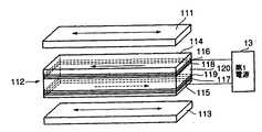
図2は、本発明の実施の形態1に係る表示装置の視野角制御ユニットを示す図である。 FIG. 2 is a diagram showing the viewing angle control unit of the display device according to Embodiment 1 of the present invention.
視野角制御ユニット11は、一対の偏光板111,113と、この一対の偏光板111,113の間に挟持された液晶パネル112とから主に構成されている。液晶パネル112は、一対の基板114,115と、基板114,115上にそれぞれ設けられた電極116,117と、電極116,117上にそれぞれ設けられた配向膜118,119と、両基板114,115の間に挟持された液晶層120とから主に構成されている。なお、実際には、必要に応じてカラーフィルタやリターデーション膜などの光学素子が設けられるが、ここでは説明を簡単にするために省略する。 The viewing
偏光板111,113は、その光軸(吸収軸又は透過軸)が略直交するように配置されている(クロスニコル)。したがって、偏光板111,113の吸収軸又は透過軸の方向が互いに略直交するように設定される。 The polarizing
基板114,115としては、ガラス基板、透明プラスチック基板、透明フィルムなどを用いることができる。 As the
電極116,117としては、ITOなどの透明電極や金属電極などを用いることができる。この電極116,117が第1電源13に接続されている。 As the
配向膜118,119としては、ポリイミド膜などの高分子膜やSiO層などの無機材料層などを挙げることができる。配向膜として高分子膜を用いる場合には、成膜した高分子膜にラビング処理を施す。配向膜として無機材料層を用いる場合には、無機材料を斜方蒸着法で被着することにより形成する。本実施の形態では、配向膜として高分子膜を用いた場合について説明する。 Examples of the
配向膜118,119に対するラビング処理の方向は、偏光板111の光軸に対して略直交し、かつ、偏光板113の光軸に対して略平行である(図中の液晶パネル内の矢印方向)。このように、配向膜118,119のラビング方向が互いに略平行であるので、液晶分子のねじれ角はほぼ0°となる。 The direction of the rubbing treatment for the
液晶層120においては、そのリターデーションを調整することにより、表示が見える方向を制御することが可能になる。リターデーション値を大きくすることにより、パネル正面(0°)からの角度が大きい位置で表示が見え、リターデーション値を小さくすることにより、パネル正面(0°)からの角度が小さい位置で表示が見える。例えば、パネル正面(0°)からの角度が約5°〜60°の範囲で表示が見えるようにするためには、リターデーション値を200nm〜1000nmに設定する。 In the liquid crystal layer 120, the direction in which the display can be seen can be controlled by adjusting the retardation. By increasing the retardation value, the display can be seen at a position where the angle from the front of the panel (0 °) is large, and by decreasing the retardation value, the display can be displayed at a position where the angle from the front of the panel (0 °) is small. appear. For example, the retardation value is set to 200 nm to 1000 nm so that the display can be seen when the angle from the front of the panel (0 °) is about 5 ° to 60 °.
次に、上記構成の視野角制御ユニット11の動作について説明する。 Next, the operation of the viewing
まず、視野角制御ユニット11に第1電源13により電圧を印加しない状態(視野角無制御モード)について説明する。視野角無制御モードでは、電源制御部15が第1電源13に電圧を印加しない指示を行う(若しくは電圧印加に関する指示が無い)。 First, a state where no voltage is applied to the viewing
液晶パネル112の液晶層120内の液晶分子は、配向膜118,119に施されたラビング処理により、その長手方向をラビング方向に沿うように配向する。視野角制御ユニット11に電圧を印加しないと、液晶分子は、その長手方向をラビング方向に沿った状態のままになる。また、偏光板111,113は、上述したように、その光軸が互いに略直交するように配置されている。 The liquid crystal molecules in the liquid crystal layer 120 of the
したがって、視野角制御ユニット11に入射された光(図中下方から偏光板111に入射する光)は、偏光板113の矢印方向に振動する光のみを透過する。上述したように、配向膜118,119に施されたラビング処理のラビング方向が互いに略平行であり、ねじれ角が略0°である。このため、この偏光板113を透過した光は、ねじれることなくそのままの状態で液晶層120を透過する。 Therefore, the light incident on the viewing angle control unit 11 (light incident on the polarizing
一方、偏光板111の光軸は、偏光板113の光軸と略直交であるので、液晶層120を透過した光は、偏光板111を透過することができない。このため、図1に示すように、視野角制御ユニット11を駆動用表示デバイス12上に配置した場合、視野角無制御モードでは、どの視野角でも(全方位で)表示は黒となる(図3における特性線B)。 On the other hand, since the optical axis of the polarizing
次いで、視野角制御ユニット11に第1電源13により電圧を印加する状態(視野角制御モード)について説明する。視野角制御モードでは、電源制御部15が第1電源13に電圧を印加する指示を行う(ここでは、3.2V)。 Next, a state in which a voltage is applied to the viewing
視野角制御ユニット11に第1電源13より電圧を印加すると、配向膜118,119により配向していた液晶分子が電界方向に揃う(液晶分子の長手方向が液晶層120の厚さ方向に揃う)。 When a voltage is applied to the viewing
視野角制御ユニット11に入射された光(図中下方から偏光板111に入射する光)は、偏光板113の矢印方向に振動する光のみを透過する。液晶層120における液晶分子は、上述したように、その長手方向が液晶層120の厚さ方向に揃う、すなわち立った状態になる。このため、この偏光板113を透過した光は、液晶分子に沿って液晶層120を透過する。 The light incident on the viewing angle control unit 11 (light incident on the
一方、偏光板111の光軸は、偏光板113の光軸と略直交であるので、液晶層120を透過した光は、偏光板111を透過することができない。このため、視野角制御ユニット11の中央部においては(正面から表示パネルを見る場合)、表示は黒となる。 On the other hand, since the optical axis of the
しかしながら、視野角制御ユニット11のサイド部においては(正面から所定の角度を有して斜めから表示パネルを見る場合)、偏光板111の光軸と液晶分子の軸方向(長手方向)との間に所定の角度が生じるので、表示は透明(白表示)になる。したがって、図1に示すように、視野角制御ユニット11を駆動用表示デバイス12上に配置した場合、視野角制御モードでは、正面から表示パネルを見ると表示は見えないが、斜めから表示パネルを見ると表示が見えるようになる(図3における特性線A)。 However, in the side portion of the viewing angle control unit 11 (when viewing the display panel from a front side with a predetermined angle), between the optical axis of the
本実施の形態に係る表示装置によれば、ユーザによる又は自動的なモード切り替えにより、特定の方向のみに表示を見せたり、特定の方向のみに表示を見せなくしたりできる。これにより、表示を見せたくない人が表示パネルの正面にいる場合に有効に利用することができる。例えば車載用モニタに本実施の形態に係る表示装置を使用し、視野角制御モードにしてドライバには表示画面が見えないようにし、助手席の人に見えるようにすることができる。 According to the display device according to the present embodiment, the display can be shown only in a specific direction, or the display can not be shown only in a specific direction, by the user or by automatic mode switching. Thereby, when the person who does not want to show a display is in the front of a display panel, it can utilize effectively. For example, the display device according to the present embodiment can be used for a vehicle-mounted monitor, and the display angle control mode can be set so that the driver cannot see the display screen and can be seen by a passenger in the passenger seat.
(実施の形態2)
本実施の形態においては、視野角制御ユニットにより、パネル正面から見たときに表示が見えるようにする場合について説明する。(Embodiment 2)
In the present embodiment, a case will be described in which the viewing angle control unit makes the display visible when viewed from the front of the panel.
図4は、本発明の実施の形態2に係る表示装置の視野角制御ユニットを示す図である。 FIG. 4 is a diagram showing a viewing angle control unit of the display device according to Embodiment 2 of the present invention.
視野角制御ユニット11は、一対の偏光板111,113と、この一対の偏光板111,113の間に挟持された液晶パネル112とから主に構成されている。液晶パネル112は、一対の基板114,115と、基板114,115上にそれぞれ設けられた電極116,117と、電極116,117上にそれぞれ設けられた配向膜118,119と、両基板114,115の間に挟持された液晶層120とから主に構成されている。なお、実際には、必要に応じてカラーフィルタやリターデーション膜などの光学素子が設けられるが、ここでは説明を簡単にするために省略する。 The viewing
偏光板111,113は、その光軸(吸収軸又は透過軸)が略平行になるように配置されている(平行ニコル)。したがって、偏光板111,113の吸収軸又は透過軸の方向が互いに略平行になるように設定される。 The
基板114,115、電極116,117及び配向膜118,119の材料としては、実施の形態1と同様のものを用いることができる。電極116,117が第1電源13に接続されている。 As the materials for the
配向膜118,119に対するラビング処理の方向は、偏光板111の光軸に対して略平行で、かつ、偏光板113の光軸に対して略平行である(図中の液晶パネル内の矢印方向)。このように、配向膜118,119のラビング方向が互いに略平行であるので、液晶分子のねじれ角はほぼ0°となる。 The direction of the rubbing treatment for the
液晶層120においては、そのリターデーションを調整することにより、表示が見える方向を制御することが可能になる。リターデーション値を大きくすることにより、パネル正面(0°)からの角度が大きい位置で表示が見え、リターデーション値を小さくすることにより、パネル正面(0°)からの角度が小さい位置で表示が見える。例えば、パネル正面(0°)からの角度が約5°〜60°の範囲で表示が見えるようにするためには、リターデーション値を200nm〜1000nmに設定する。 In the liquid crystal layer 120, the direction in which the display can be seen can be controlled by adjusting the retardation. By increasing the retardation value, the display can be seen at a position where the angle from the front of the panel (0 °) is large, and by decreasing the retardation value, the display can be displayed at a position where the angle from the front of the panel (0 °) is small. appear. For example, the retardation value is set to 200 nm to 1000 nm so that the display can be seen when the angle from the front of the panel (0 °) is about 5 ° to 60 °.
次に、上記構成の視野角制御ユニット11の動作について説明する。 Next, the operation of the viewing
まず、視野角制御ユニット11に第1電源13により電圧を印加しない状態(視野角無制御モード)について説明する。視野角無制御モードでは、電源制御部15が第1電源13に電圧を印加しない指示を行う(若しくは電圧印加に関する指示が無い)。 First, a state where no voltage is applied to the viewing
液晶パネル112の液晶層120内の液晶分子は、配向膜118,119に施されたラビング処理により、その長手方向をラビング方向に沿うように配向する。視野角制御ユニット11に電圧を印加しないと、液晶分子は、その長手方向をラビング方向に沿った状態のままになる。また、偏光板111,113は、上述したように、その光軸が互いに略平行になるように配置されている。 The liquid crystal molecules in the liquid crystal layer 120 of the
したがって、視野角制御ユニット11に入射された光(図中下方から偏光板111に入射する光)は、偏光板113の矢印方向に振動する光のみを透過する。上述したように、配向膜118,119に施されたラビング処理のラビング方向が互いに略平行であり、ねじれ角が略0°である。このため、この偏光板113を透過した光は、ねじれることなくそのままの状態で液晶層120を透過する。 Therefore, the light incident on the viewing angle control unit 11 (light incident on the
一方、偏光板111の光軸は、偏光板113の光軸と略平行であるので、液晶層120を透過した光は、偏光板111も透過する。このため、図1に示すように、視野角制御ユニット11を駆動用表示デバイス12上に配置した場合、視野角無制御モードでは、どの視野角でも(全方位で)表示は透明(白表示)となる(図5における特性線D)。 On the other hand, since the optical axis of the
次いで、視野角制御ユニット11に第1電源13により電圧を印加する状態(視野角制御モード)について説明する。視野角制御モードでは、電源制御部15が第1電源13に電圧を印加する指示を行う(ここでは、3.2V)。 Next, a state in which a voltage is applied to the viewing
視野角制御ユニット11に第1電源13より電圧を印加すると、配向膜118,119により配向していた液晶分子が電界方向に揃う(液晶分子の長手方向が液晶層12の厚さ方向に揃う)。 When a voltage is applied to the viewing
視野角制御ユニット11に入射された光(図中下方から偏光板111に入射する光)は、偏光板113の矢印方向に振動する光のみを透過する。液晶層120における液晶分子は、上述したように、その長手方向が液晶層120の厚さ方向に揃う、すなわち立った状態になる。このため、この偏光板113を透過した光は、液晶分子に沿って液晶層120を透過する。 The light incident on the viewing angle control unit 11 (light incident on the
一方、偏光板111の光軸は、偏光板113の光軸と略平行であるので、液晶層120を透過した光は、偏光板111も透過することができる。このため、視野角制御ユニット11の中央部においては(正面から表示パネルを見る場合)、表示は透明となる。 On the other hand, since the optical axis of the
しかしながら、視野角制御ユニット11のサイド部においては(正面から所定の角度を有して斜めから表示パネルを見る場合)、偏光板111の光軸と液晶分子の軸方向(長手方向)との間に所定の角度が生じるので、表示は黒になる。したがって、図1に示すように、視野角制御ユニット11を駆動用表示デバイス12上に配置した場合、視野角制御モードでは、正面から表示パネルを見ると表示は見えるが、斜めから表示パネルを見ると表示が見えないようになる(図5における特性線C)。 However, in the side portion of the viewing angle control unit 11 (when viewing the display panel from a front side with a predetermined angle), between the optical axis of the
本実施の形態に係る表示装置によれば、ユーザによる又は自動的なモード切り替えにより、特定の方向のみに表示を見せたり、特定の方向のみに表示を見せなくしたりできる。これにより、表示を見せたくない人が表示パネルの両側(正面から所定の角度を有した位置)にいる場合に有効に利用することができる。例えばPDAに本実施の形態に係る表示装置を使用し、個人情報などを表示させているときに視野角制御モードにし、写真画像などを他の人にも見せるときに視野角無制御モードにする。 According to the display device according to the present embodiment, the display can be shown only in a specific direction, or the display can not be shown only in a specific direction, by the user or by automatic mode switching. Thereby, it can utilize effectively when the person who does not want to show a display is in the both sides (position which had a predetermined angle from the front) of a display panel. For example, when the display device according to the present embodiment is used for a PDA and personal information or the like is displayed, the viewing angle control mode is set, and when a photograph image or the like is shown to other people, the viewing angle no control mode is set. .
この視野角制御ユニットは、各構成要素をフィルム状にすることにより、厚さを数ミクロンオーダーにすることが可能である。このため、視野角制御ユニット全体をシート状に形成することができ、表示デバイスの厚さを増加させずに、表示面上に簡単に配置することが可能となる。 In this viewing angle control unit, the thickness of each component can be set to the order of several microns by forming a film. For this reason, the entire viewing angle control unit can be formed in a sheet shape, and can be easily arranged on the display surface without increasing the thickness of the display device.
本発明は上記実施の形態1,2に限定されず、種々変更して実施することが可能である。例えば、上記実施の形態1,2において挙げた材料や数値などは例示でありこれに限定されず、同種の効果を発揮するのであれば種々変更することが可能である。 The present invention is not limited to Embodiments 1 and 2 above, and can be implemented with various modifications. For example, the materials, numerical values, and the like given in the first and second embodiments are examples and are not limited thereto, and various modifications can be made as long as the same type of effect is exhibited.
本発明は、LCD、EL、PDP又はCRTなどの発光型及び受光型の表示デバイスに有効に適用することができる。 The present invention can be effectively applied to light-emitting and light-receiving display devices such as LCD, EL, PDP, and CRT.
Claims (19)
Translated fromJapaneseApplications Claiming Priority (2)
| Application Number | Priority Date | Filing Date | Title |
|---|---|---|---|
| IB0303800 | 2003-08-22 | ||
| PCT/IB2004/051455WO2005019919A1 (en) | 2003-08-22 | 2004-08-13 | Display apparatus and viewing angle controlling unit |
Publications (1)
| Publication Number | Publication Date |
|---|---|
| JP2007503603Atrue JP2007503603A (en) | 2007-02-22 |
Family
ID=34204112
Family Applications (1)
| Application Number | Title | Priority Date | Filing Date |
|---|---|---|---|
| JP2006523736APendingJP2007503603A (en) | 2003-08-22 | 2004-08-13 | Display device and viewing angle control unit used therefor |
Country Status (7)
| Country | Link |
|---|---|
| US (1) | US20060203165A1 (en) |
| EP (1) | EP1658523A1 (en) |
| JP (1) | JP2007503603A (en) |
| KR (1) | KR20060133947A (en) |
| CN (1) | CN100464237C (en) |
| TW (1) | TW200512517A (en) |
| WO (1) | WO2005019919A1 (en) |
Cited By (2)
| Publication number | Priority date | Publication date | Assignee | Title |
|---|---|---|---|---|
| US8228476B2 (en) | 2008-10-29 | 2012-07-24 | Chimei Innolux Corporation | Horizontal electric field type liquid crystal display device |
| WO2018109991A1 (en)* | 2016-12-12 | 2018-06-21 | シャープ株式会社 | Display device, electronic mirror, display device control method, program, and storage medium |
Families Citing this family (14)
| Publication number | Priority date | Publication date | Assignee | Title |
|---|---|---|---|---|
| EP1807732B1 (en) | 2004-10-25 | 2008-10-01 | Koninklijke Philips Electronics N.V. | Display device |
| JP2006330164A (en)* | 2005-05-24 | 2006-12-07 | Casio Comput Co Ltd | Liquid crystal display |
| JP4309871B2 (en)* | 2005-06-14 | 2009-08-05 | 株式会社東芝 | Information processing apparatus, method, and program |
| JP2006350106A (en)* | 2005-06-17 | 2006-12-28 | Casio Comput Co Ltd | Liquid crystal display |
| JP4490886B2 (en) | 2005-07-29 | 2010-06-30 | 株式会社東芝 | Information processing device |
| JP4282641B2 (en)* | 2005-07-29 | 2009-06-24 | 株式会社東芝 | Information processing device |
| JP2007121970A (en)* | 2005-10-31 | 2007-05-17 | Toshiba Corp | Information processing apparatus and control method thereof |
| EP1826604B1 (en)* | 2006-01-31 | 2015-12-23 | Semiconductor Energy Laboratory Co., Ltd. | Display device |
| WO2007094386A1 (en)* | 2006-02-17 | 2007-08-23 | Sharp Kabushiki Kaisha | Display and view angle control device used for the same |
| KR100816078B1 (en)* | 2006-06-19 | 2008-03-24 | 광운대학교 산학협력단 | Spatial image projector and its method |
| US8269929B2 (en)* | 2006-09-28 | 2012-09-18 | Stanley Electric Co., Ltd. | Vertically aligned liquid crystal display device with visual angle compensation |
| CN101685210B (en)* | 2008-09-22 | 2011-01-19 | 纬创资通股份有限公司 | Image processing system and method capable of changing polarization angle of polarized image |
| JP2010122572A (en)* | 2008-11-21 | 2010-06-03 | Sony Corp | Display device, method for driving the same, and electronic device |
| US10739625B2 (en)* | 2018-08-29 | 2020-08-11 | Innolux Corporation | Display device |
Citations (6)
| Publication number | Priority date | Publication date | Assignee | Title |
|---|---|---|---|---|
| JPH0659287A (en)* | 1992-03-31 | 1994-03-04 | Toshiba Corp | Liquid crystal display |
| JPH08114795A (en)* | 1994-10-17 | 1996-05-07 | Toshiba Corp | Display device and display system using the same |
| JPH0973070A (en)* | 1995-09-06 | 1997-03-18 | Seiko Epson Corp | Viewing angle limiting device and image display device using the same |
| JPH09105958A (en)* | 1995-10-13 | 1997-04-22 | Sharp Corp | Variable viewing angle element and variable viewing angle liquid crystal display device using the same |
| JPH10197844A (en)* | 1997-01-09 | 1998-07-31 | Sharp Corp | Liquid crystal display |
| JPH11174489A (en)* | 1997-12-17 | 1999-07-02 | Matsushita Electric Ind Co Ltd | Liquid crystal display |
Family Cites Families (9)
| Publication number | Priority date | Publication date | Assignee | Title |
|---|---|---|---|---|
| US3785721A (en)* | 1971-07-15 | 1974-01-15 | Int Liquid Xtal Co | Display devices utilizing liquid crystal light modulation with varying colors |
| FR2349849A1 (en)* | 1976-04-30 | 1977-11-25 | Commissariat Energie Atomique | ANALOGUE LIQUID CRYSTAL DISPLAY DEVICE |
| JPH075515Y2 (en)* | 1988-02-05 | 1995-02-08 | 日産自動車株式会社 | Vehicle image display device |
| JP2975844B2 (en)* | 1993-06-24 | 1999-11-10 | 三洋電機株式会社 | Liquid crystal display |
| JPH07212639A (en)* | 1994-01-25 | 1995-08-11 | Sony Corp | Electronic shutter device for television cameras |
| JP3184069B2 (en)* | 1994-09-02 | 2001-07-09 | シャープ株式会社 | Image display device |
| US6181401B1 (en)* | 1998-08-07 | 2001-01-30 | Honeywell International Inc. | Liquid crystal display with reduced off state luminance |
| JP4425496B2 (en)* | 2001-07-03 | 2010-03-03 | アルパイン株式会社 | Display device |
| KR20060058704A (en)* | 2003-08-06 | 2006-05-30 | 코닌클리즈케 필립스 일렉트로닉스 엔.브이. | Liquid crystal display device and driving method of liquid crystal display device |
- 2004
- 2004-08-13KRKR1020067003521Apatent/KR20060133947A/ennot_activeCeased
- 2004-08-13JPJP2006523736Apatent/JP2007503603A/enactivePending
- 2004-08-13USUS10/568,558patent/US20060203165A1/ennot_activeAbandoned
- 2004-08-13CNCNB2004800239873Apatent/CN100464237C/ennot_activeExpired - Fee Related
- 2004-08-13WOPCT/IB2004/051455patent/WO2005019919A1/ennot_activeApplication Discontinuation
- 2004-08-13EPEP04769807Apatent/EP1658523A1/ennot_activeCeased
- 2004-08-20TWTW093125213Apatent/TW200512517A/enunknown
Patent Citations (6)
| Publication number | Priority date | Publication date | Assignee | Title |
|---|---|---|---|---|
| JPH0659287A (en)* | 1992-03-31 | 1994-03-04 | Toshiba Corp | Liquid crystal display |
| JPH08114795A (en)* | 1994-10-17 | 1996-05-07 | Toshiba Corp | Display device and display system using the same |
| JPH0973070A (en)* | 1995-09-06 | 1997-03-18 | Seiko Epson Corp | Viewing angle limiting device and image display device using the same |
| JPH09105958A (en)* | 1995-10-13 | 1997-04-22 | Sharp Corp | Variable viewing angle element and variable viewing angle liquid crystal display device using the same |
| JPH10197844A (en)* | 1997-01-09 | 1998-07-31 | Sharp Corp | Liquid crystal display |
| JPH11174489A (en)* | 1997-12-17 | 1999-07-02 | Matsushita Electric Ind Co Ltd | Liquid crystal display |
Cited By (2)
| Publication number | Priority date | Publication date | Assignee | Title |
|---|---|---|---|---|
| US8228476B2 (en) | 2008-10-29 | 2012-07-24 | Chimei Innolux Corporation | Horizontal electric field type liquid crystal display device |
| WO2018109991A1 (en)* | 2016-12-12 | 2018-06-21 | シャープ株式会社 | Display device, electronic mirror, display device control method, program, and storage medium |
Also Published As
| Publication number | Publication date |
|---|---|
| KR20060133947A (en) | 2006-12-27 |
| TW200512517A (en) | 2005-04-01 |
| CN100464237C (en) | 2009-02-25 |
| US20060203165A1 (en) | 2006-09-14 |
| CN1839341A (en) | 2006-09-27 |
| WO2005019919A1 (en) | 2005-03-03 |
| EP1658523A1 (en) | 2006-05-24 |
Similar Documents
| Publication | Publication Date | Title |
|---|---|---|
| TWI341951B (en) | Liquid crystal display device which can control viewing angle and electronic device using same | |
| CN1332256C (en) | Viewing angle control element, display device, and electronic apparatus | |
| US7817106B2 (en) | Display device, viewing angle control device, and electronic apparatus | |
| US7834834B2 (en) | Display device, viewing angle control device, and electronic apparatus | |
| US7760301B2 (en) | Liquid crystal device and electronic apparatus | |
| JP2007503603A (en) | Display device and viewing angle control unit used therefor | |
| CN103531100B (en) | Display device and operating method thereof | |
| US8184145B2 (en) | Display device and electronic apparatus | |
| JP2007047229A (en) | Variable viewing angle liquid crystal display device, method and terminal | |
| JPH07146473A (en) | Liquid crystal display device | |
| JP2005534969A (en) | Transflective liquid crystal display device | |
| JP4347163B2 (en) | Display device and electronic device | |
| JP5241822B2 (en) | Display panel and camera | |
| KR101141944B1 (en) | Liquid crystal display and method for fabricating the same | |
| JP4470904B2 (en) | Viewing angle control element, display device, and electronic device | |
| US7626656B2 (en) | LCD device for switching display mode between wide viewing angle and narrow viewing angle and method employing control cell for controlling tilt angle of molecules of dichroic liquid crystal layer therein | |
| JP2008051993A (en) | Electro-optical device, viewing angle control element, and electronic apparatus | |
| JP2006072239A (en) | Display device, polarizer, and viewing angle control device | |
| JP2007114394A (en) | Display device | |
| JP2006047550A (en) | Viewing angle control device | |
| JP2007155817A (en) | Display device | |
| WO2007139193A1 (en) | Display and filed-of-view angle control device used in the same | |
| CN101067695A (en) | View angle control element, display device and electronic equipment | |
| HK1096158B (en) | Liquid crystal display device which can control viewing angle and electronic device using same |
Legal Events
| Date | Code | Title | Description |
|---|---|---|---|
| A621 | Written request for application examination | Free format text:JAPANESE INTERMEDIATE CODE: A621 Effective date:20070315 | |
| A711 | Notification of change in applicant | Free format text:JAPANESE INTERMEDIATE CODE: A711 Effective date:20070219 | |
| A131 | Notification of reasons for refusal | Free format text:JAPANESE INTERMEDIATE CODE: A131 Effective date:20100604 | |
| A02 | Decision of refusal | Free format text:JAPANESE INTERMEDIATE CODE: A02 Effective date:20110107 |