JP2007503025A - Adjustable mirror - Google Patents
Adjustable mirrorDownload PDFInfo
- Publication number
- JP2007503025A JP2007503025AJP2006530788AJP2006530788AJP2007503025AJP 2007503025 AJP2007503025 AJP 2007503025AJP 2006530788 AJP2006530788 AJP 2006530788AJP 2006530788 AJP2006530788 AJP 2006530788AJP 2007503025 AJP2007503025 AJP 2007503025A
- Authority
- JP
- Japan
- Prior art keywords
- meniscus
- fluid
- mirror
- optical axis
- adjustable mirror
- Prior art date
- Legal status (The legal status is an assumption and is not a legal conclusion. Google has not performed a legal analysis and makes no representation as to the accuracy of the status listed.)
- Withdrawn
Links
- 239000012530fluidSubstances0.000claimsabstractdescription105
- 230000003287optical effectEffects0.000claimsabstractdescription93
- 230000005499meniscusEffects0.000claimsabstractdescription80
- 230000008859changeEffects0.000claimsabstractdescription13
- 238000000034methodMethods0.000claimsdescription13
- 230000000694effectsEffects0.000claimsdescription9
- 230000008901benefitEffects0.000claimsdescription4
- 238000004519manufacturing processMethods0.000claimsdescription4
- 238000005286illuminationMethods0.000claimsdescription3
- 230000005670electromagnetic radiationEffects0.000claimsdescription2
- 239000007788liquidSubstances0.000description10
- 230000002209hydrophobic effectEffects0.000description7
- 239000012528membraneSubstances0.000description7
- VYPSYNLAJGMNEJ-UHFFFAOYSA-NSilicium dioxideChemical compoundO=[Si]=OVYPSYNLAJGMNEJ-UHFFFAOYSA-N0.000description4
- LYCAIKOWRPUZTN-UHFFFAOYSA-NEthylene glycolChemical compoundOCCOLYCAIKOWRPUZTN-UHFFFAOYSA-N0.000description3
- 239000000463materialSubstances0.000description3
- 239000000203mixtureSubstances0.000description3
- 238000005086pumpingMethods0.000description3
- 239000011248coating agentSubstances0.000description2
- 238000000576coating methodMethods0.000description2
- 230000005660hydrophilic surfaceEffects0.000description2
- 230000004044responseEffects0.000description2
- 235000012239silicon dioxideNutrition0.000description2
- 239000000377silicon dioxideSubstances0.000description2
- 239000007787solidSubstances0.000description2
- XLYOFNOQVPJJNP-UHFFFAOYSA-NwaterSubstancesOXLYOFNOQVPJJNP-UHFFFAOYSA-N0.000description2
- 230000009471actionEffects0.000description1
- 150000001335aliphatic alkanesChemical class0.000description1
- 230000005540biological transmissionEffects0.000description1
- 239000004020conductorSubstances0.000description1
- 230000007423decreaseEffects0.000description1
- 230000003247decreasing effectEffects0.000description1
- 230000002950deficientEffects0.000description1
- 238000004720dielectrophoresisMethods0.000description1
- 238000001962electrophoresisMethods0.000description1
- 230000009969flowable effectEffects0.000description1
- 239000007789gasSubstances0.000description1
- 239000011521glassSubstances0.000description1
- 230000005484gravityEffects0.000description1
- 230000005661hydrophobic surfaceEffects0.000description1
- AMGQUBHHOARCQH-UHFFFAOYSA-Nindium;oxotinChemical compound[In].[Sn]=OAMGQUBHHOARCQH-UHFFFAOYSA-N0.000description1
- 230000008569processEffects0.000description1
- 230000005855radiationEffects0.000description1
- 150000003839saltsChemical class0.000description1
- 229920002545silicone oilPolymers0.000description1
- 239000000126substanceSubstances0.000description1
- 238000009736wettingMethods0.000description1
Images


Classifications
- G—PHYSICS
- G02—OPTICS
- G02B—OPTICAL ELEMENTS, SYSTEMS OR APPARATUS
- G02B26/00—Optical devices or arrangements for the control of light using movable or deformable optical elements
- G02B26/02—Optical devices or arrangements for the control of light using movable or deformable optical elements for controlling the intensity of light
- G—PHYSICS
- G02—OPTICS
- G02B—OPTICAL ELEMENTS, SYSTEMS OR APPARATUS
- G02B3/00—Simple or compound lenses
- G02B3/12—Fluid-filled or evacuated lenses
- G02B3/14—Fluid-filled or evacuated lenses of variable focal length
- G—PHYSICS
- G02—OPTICS
- G02B—OPTICAL ELEMENTS, SYSTEMS OR APPARATUS
- G02B26/00—Optical devices or arrangements for the control of light using movable or deformable optical elements
- G02B26/004—Optical devices or arrangements for the control of light using movable or deformable optical elements based on a displacement or a deformation of a fluid
- G02B26/005—Optical devices or arrangements for the control of light using movable or deformable optical elements based on a displacement or a deformation of a fluid based on electrowetting
- G—PHYSICS
- G02—OPTICS
- G02B—OPTICAL ELEMENTS, SYSTEMS OR APPARATUS
- G02B26/00—Optical devices or arrangements for the control of light using movable or deformable optical elements
- G02B26/08—Optical devices or arrangements for the control of light using movable or deformable optical elements for controlling the direction of light
- G02B26/0816—Optical devices or arrangements for the control of light using movable or deformable optical elements for controlling the direction of light by means of one or more reflecting elements
- H—ELECTRICITY
- H01—ELECTRIC ELEMENTS
- H01S—DEVICES USING THE PROCESS OF LIGHT AMPLIFICATION BY STIMULATED EMISSION OF RADIATION [LASER] TO AMPLIFY OR GENERATE LIGHT; DEVICES USING STIMULATED EMISSION OF ELECTROMAGNETIC RADIATION IN WAVE RANGES OTHER THAN OPTICAL
- H01S3/00—Lasers, i.e. devices using stimulated emission of electromagnetic radiation in the infrared, visible or ultraviolet wave range
- H01S3/05—Construction or shape of optical resonators; Accommodation of active medium therein; Shape of active medium
- H01S3/08—Construction or shape of optical resonators or components thereof
- H01S3/08059—Constructional details of the reflector, e.g. shape
- H—ELECTRICITY
- H01—ELECTRIC ELEMENTS
- H01S—DEVICES USING THE PROCESS OF LIGHT AMPLIFICATION BY STIMULATED EMISSION OF RADIATION [LASER] TO AMPLIFY OR GENERATE LIGHT; DEVICES USING STIMULATED EMISSION OF ELECTROMAGNETIC RADIATION IN WAVE RANGES OTHER THAN OPTICAL
- H01S5/00—Semiconductor lasers
- H01S5/10—Construction or shape of the optical resonator, e.g. extended or external cavity, coupled cavities, bent-guide, varying width, thickness or composition of the active region
- H01S5/18—Surface-emitting [SE] lasers, e.g. having both horizontal and vertical cavities
- H01S5/183—Surface-emitting [SE] lasers, e.g. having both horizontal and vertical cavities having only vertical cavities, e.g. vertical cavity surface-emitting lasers [VCSEL]
- H—ELECTRICITY
- H01—ELECTRIC ELEMENTS
- H01S—DEVICES USING THE PROCESS OF LIGHT AMPLIFICATION BY STIMULATED EMISSION OF RADIATION [LASER] TO AMPLIFY OR GENERATE LIGHT; DEVICES USING STIMULATED EMISSION OF ELECTROMAGNETIC RADIATION IN WAVE RANGES OTHER THAN OPTICAL
- H01S3/00—Lasers, i.e. devices using stimulated emission of electromagnetic radiation in the infrared, visible or ultraviolet wave range
- H01S3/10—Controlling the intensity, frequency, phase, polarisation or direction of the emitted radiation, e.g. switching, gating, modulating or demodulating
- H01S3/105—Controlling the intensity, frequency, phase, polarisation or direction of the emitted radiation, e.g. switching, gating, modulating or demodulating by controlling the mutual position or the reflecting properties of the reflectors of the cavity, e.g. by controlling the cavity length
Landscapes
- Physics & Mathematics (AREA)
- Optics & Photonics (AREA)
- General Physics & Mathematics (AREA)
- Electromagnetism (AREA)
- Engineering & Computer Science (AREA)
- Plasma & Fusion (AREA)
- Condensed Matter Physics & Semiconductors (AREA)
- Mechanical Light Control Or Optical Switches (AREA)
- Optical Elements Other Than Lenses (AREA)
Abstract
Translated fromJapaneseDescription
Translated fromJapanese本発明は、調節可能なミラーに、調節可能なミラーを含む光学デバイスに、並びに、このようなミラー及びこのようなデバイスを製造する方法に、関する。 The present invention relates to adjustable mirrors, optical devices comprising adjustable mirrors, and methods of manufacturing such mirrors and such devices.
ミラーは、光を反射させるために配置されるデバイスである。用語の“光”は、可視の電磁放射及び他の波長の電磁放射の両方を含むことが理解される。 A mirror is a device that is arranged to reflect light. It is understood that the term “light” includes both visible and other wavelengths of electromagnetic radiation.
調節可能なミラーは、その反射の特性を制御可能に調節することができるミラーである。例えば、その反射面の形状(若しくは装置の形状)を、変えてもよいか、又は、その反射面の位置(又は装置の位置)を、変えてもよい。 An adjustable mirror is a mirror that can controllably adjust its reflection characteristics. For example, the shape of the reflecting surface (or the shape of the device) may be changed, or the position of the reflecting surface (or the position of the device) may be changed.
調節可能なミラーの一つのタイプは、変形可能なミラーであり、そのミラーにおいては、そのミラーの反射面を、所望の形状を提供するために、制御可能に変形することができる。例えば、球面のミラーの反射面を、そのミラーの曲率半径を変えるために、制御可能に変形させてもよい。このような変形可能なミラーは、典型的には、反射望遠鏡で使用される。 One type of adjustable mirror is a deformable mirror, in which the reflective surface of the mirror can be controllably deformed to provide a desired shape. For example, the reflective surface of a spherical mirror may be controllably deformed to change the radius of curvature of the mirror. Such deformable mirrors are typically used in reflective telescopes.
特許文献1は、光ディスク記録/再生装置に用いられる変形可能なミラーを記述する。そのミラーは、反射面を有する柔軟な部材を制御可能に変形することによって、調節され、その部材は、静電圧力によって変形される。
このような変形可能なミラーは、そのミラーが、所望の形状を得るために、継続的に応力を加えられ、応力を解放させられると、摩耗に対して敏感である。さらに、所望の様式で反射面を変形させることは、制御することが困難であると共に、その結果として、良好な光学的特性の変形可能な光学ミラーを提供することは、相対的に高価である。 Such deformable mirrors are sensitive to wear when they are continuously stressed and relieved to obtain the desired shape. Furthermore, deforming the reflective surface in the desired manner is difficult to control and, as a result, providing a deformable optical mirror with good optical properties is relatively expensive. .
特許文献2は、図1A及び1Bに図解するような、代替の調節可能なミラー10を記述する。ミラー系10は、流体14で満たされた膜12を含む。膜12内の流体14の圧力は、ポンプ16によって制御される。膜12は、可変レンズとして作用し、且つ、そのレンズの形状(よって、パワー)は、流体14の圧力に依存して変動する。図1Aは、低い圧力での流体14を、すなわち、膜12が両凹レンズを形成することを、示す。図1Bは、高い圧力での流体14を、膜12が両凸レンズを形成することを、示す。 U.S. Patent No. 6,057,031 describes an alternative
膜12の一つの表面の中央の部分18に付けられるのは、硬質の凸の反射面20である。膜12及び反射面20によって形成されたミラー10は、流体14の圧力を変動させることによって、調節される。その結果として、膜12によって形成されたレンズのパワーが、変えられ、よって、そのミラーのみかけの曲率(すなわち、膜12及び湾曲させられた反射面20によって作り出されたレンズの形状の結果である、そのミラーの合計のパワー)が、調節される。このような系の不都合は、その膜の表面及びその反射面の移動のおかげで、良好な光学特性を維持することが、困難であると共にそれが、振動に対して敏感であることである。さらに、それは、機械的な摩耗に対して敏感である。
本発明の実施形態の目的は、ここで参照されるのであろうと別に参照されるのであろうと、先行技術の一つ以上の問題を扱う調節可能なミラーを提供することである。また、本発明の目的は、このような改善された調節可能なミラーを組み込む光学デバイスを、並びに、このような改善された調節可能なミラー及びこのような光学デバイスを製造する方法を、提供することでもある。 It is an object of embodiments of the present invention to provide an adjustable mirror that addresses one or more problems of the prior art, whether referred to herein or otherwise. It is also an object of the present invention to provide an optical device incorporating such an improved adjustable mirror, as well as a method of manufacturing such an improved adjustable mirror and such an optical device. It is also a thing.
本発明の特定の実施形態の目的は、光路が、動作中における機械的な摩耗及び引き裂きに対して相対的に敏感でない、調節可能なミラーを提供することである。 It is an object of certain embodiments of the invention to provide an adjustable mirror whose optical path is relatively insensitive to mechanical wear and tear during operation.
第一の態様において、本発明は、光軸を横断して広がるメニスカスにわたって接触している第一の流体及び第二の流体を含む調節可能なミラーを提供し、それら流体は、実質的に不混和性であると共に異なる屈折率を有し、その調節可能なミラーは、その光軸を横断して広がる反射面、及びそのメニスカスの形状及び位置の少なくとも一つを制御可能に変えるために配置されたメニスカス調節器を含む。 In a first aspect, the present invention provides an adjustable mirror that includes a first fluid and a second fluid that are in contact over a meniscus extending across the optical axis, the fluid being substantially non-defective. The adjustable mirror, which is miscible and has a different refractive index, is arranged to controllably change at least one of the reflecting surface extending across the optical axis and the meniscus shape and position. Including a meniscus regulator.
それら二つの流体の間の界面は、入射する放射の方向を変化させるように作用することができる、たとえば、その界面は、レンズ又はビーム偏向器として作用することができる。この界面の形状又は位置を変動させることによって、そのミラーの有効な光学特性(すなわち、パワー、みかけの位置、又はみかけの配向)を、調節することができる。移動する機械的な部分が、このような調節可能なミラーの光路内に要求されないので、そのミラーの性能は、機械的な摩耗及び引き裂きに対して相対的に免除されたものである。 The interface between the two fluids can act to change the direction of incident radiation, for example, the interface can act as a lens or beam deflector. By varying the shape or position of this interface, the effective optical properties of the mirror (ie, power, apparent position, or apparent orientation) can be adjusted. Since no moving mechanical part is required in the optical path of such an adjustable mirror, the performance of the mirror is relatively immune to mechanical wear and tear.
別の態様において、本発明は、光軸を横断して広がるメニスカスにわたって接触している第一の流体及び第二の流体を含む光学デバイスを提供し、それら流体は、実質的に不混和性であると共に異なる屈折率を有し、その光学デバイスは、その光軸を横断して広がる反射面、及びそのメニスカスの形状及び位置の少なくとも一つを制御可能に変えるために配置されたメニスカス調節器を含む。 In another aspect, the present invention provides an optical device that includes a first fluid and a second fluid that are in contact across a meniscus extending across an optical axis, the fluids being substantially immiscible. The optical device includes a reflective surface extending across the optical axis and a meniscus adjuster arranged to controllably alter at least one of the shape and position of the meniscus. Including.
さらなる態様において、本発明は、調節可能なミラーを製造する方法を提供し、その方法は、光軸を実質的に横断して広がるメニスカスにわたって接触している第一の流体及び第二の流体を提供するステップを含み、それら流体は、実質的に不混和性であると共に異なる屈折率を有し、その方法は、その光軸を横断して広がる反射面を提供するステップ、及びそのメニスカスの形状及び位置の少なくとも一つを変えるために配置されたメニスカス調節器を提供するステップを含む。 In a further aspect, the present invention provides a method of manufacturing an adjustable mirror, the method comprising: a first fluid and a second fluid in contact over a meniscus extending substantially across the optical axis. The fluids are substantially immiscible and have different refractive indices, the method comprising providing a reflective surface extending across the optical axis, and the shape of the meniscus And providing a meniscus adjuster arranged to change at least one of the positions.
別の態様において、本発明は、光学デバイスを動作させる方法を提供し、その光学デバイスは、光軸を横断して広がるメニスカスにわたって接触している第一の流体及び第二の流体を含み、それら流体は、実質的に不混和性であると共に異なる屈折率を有し、その光学デバイスは、その光軸を横断して広がる反射面を含み、その方法は、そのミラーが、所望の反射の特性を提供するように、そのメニスカスの形状及び位置の少なくとも一つを制御可能に変えることを含む。 In another aspect, the present invention provides a method of operating an optical device, the optical device comprising a first fluid and a second fluid in contact across a meniscus extending across an optical axis, and The fluid is substantially immiscible and has a different index of refraction, and the optical device includes a reflective surface that extends across the optical axis, the method wherein the mirror has the desired reflective properties. To controllably change at least one of the shape and position of the meniscus.
本発明の他の目的及び利点は、添付する特許請求の範囲に提示されるような好適な特徴から明らかであると思われる。 Other objects and advantages of the invention will be apparent from the preferred features as set forth in the appended claims.
本発明のより良好な理解のために、及び、それらの実施形態を実施する方法を示すために、今、一例として、添付する概略的な図面を参照することにする。 For a better understanding of the present invention and to show how to implement those embodiments, reference will now be made, by way of example, to the accompanying schematic drawings.
図2Aは、本発明の第一の実施形態と一致した調節可能なミラー100を示す。ミラー100を、二つの別個の素子で、すなわち、反射面110及び異なる屈折率の二つの流体130、140で形成された可変レンズで、形成されるものとみなすことができる。 FIG. 2A shows an
流体は、どんな力に応じてもそれの形状を変える、流れる又はチャンバーの輪郭に一致する傾向にある、並びに、気体、液体、並びに流れの可能な固体及び液体の混合物を含む、物質である。 A fluid is a substance that changes its shape in response to any force, tends to flow or conform to the contour of the chamber, and includes gases, liquids, and flowable solids and liquid mixtures.
それら二つの流体は、実質的に不混和性である、すなわち、それら二つの流体は、混合しない。このように、それら流体が、異なる屈折率を有すると、レンズの機能は、それら二つの流体の接触領域に沿って形成されたメニスカス150によって、提供される。レンズの機能は、一つ以上の波長の光を集束させる(収束させる又は発散させる)メニスカス150の能力である。 The two fluids are substantially immiscible, i.e. the two fluids do not mix. Thus, if the fluids have different refractive indices, the lens function is provided by the
メニスカス150は、ミラー100の光軸90を横断して延びる。用語の“横断して”は、そのメニスカスが、その光軸と交差する(すなわち、それは、その光軸を横切って延びる)と共に、それが、その光軸に平行ではないことを示唆する。メニスカス150は、どんな所望の角度においても、光軸90と交差してもよい。また、反射面110は、光軸90を横切って延び、且つ、その反射面は、そのメニスカスに向かって面する。それら流体は、表面120、122によって定義されたチャンバー125内に閉じ込められる。少なくとも、光軸90に沿って存在するチャンバー125の壁120、122の部分は、透明である。典型的には、そのチャンバーの所望の部分内にそれら流体を位置させるために、そのチャンバーの異なる領域は、各々の流体がぞれぞれの領域へ誘引されることになるように、各々の流体について異なる湿潤性を有することになる。湿潤性は、ある領域が流体によって湿潤させられる(覆われる)程度である。例えば、流体130が有極性の流体であると共に流体140が無極性の流体であるとすれば、反射面110の上に存在する透明な領域122は、有極性の流体130を誘引すると共に無極性の流体140を誘引しないように、親水性であってもよい。 The
調節可能なレンズ100によって提供されたそのミラーの機能が、メニスカス150によって提供されたレンズの機能及び反射面110によって提供された反射の機能の結果であることは、認識されると思われる。この特定の実施形態においては、その反射面は、平面である。この特定の例においては、そのメニスカスは、(流体130から目視すると)凸であり、且つ流体130は、流体140よりも高い屈折率を有する。 It will be appreciated that the mirror function provided by the
その結果として、調節可能なミラー100によって提供された結果として生じる光学的な機能は、図2Bに図解されるような凹面のミラー190のものである。 Consequently, the resulting optical function provided by the
その光軸に沿ったそのメニスカスの位置(すなわち、その反射面に対するそのメニスカスの位置)又はそのメニスカスの形状のいずれかを調節することによって、その調節可能なミラーによって提供されたそのミラーの機能を、変化させることができる。例えば、メニスカス150が、より凸に作られる、すなわち、それが、点線150’によって示された形状をとるとすれば、結果として生じるミラーの機能は、すなわち、点線190’によって示唆されるように、より小さい曲率半径を有するミラーのものであることになる。 By adjusting either the position of the meniscus along the optical axis (ie, the position of the meniscus relative to the reflective surface) or the shape of the meniscus, the function of the mirror provided by the adjustable mirror is Can be changed. For example, if
メニスカス調節器は、メニスカス150の形状及び位置の少なくとも一つを変えるために、使用される。ある容積の流体の少なくとも一つを変位させる(ある容積の流体の少なくとも一つの位置又は形状を変化させる)(及び、その結果として、メニスカス150の形状を変化させる)様々な方法は、例えば、国際公開第02/069016号パンフレット内に記載されている。 The meniscus adjuster is used to change at least one of the shape and position of the
好ましくは、そのメニスカスの形状は、エレクトロウェッティングの効果を利用することによって、変化させられる。エレクトロウェッティングにおいては、三相の接触角が、印加電圧と共に変化させられる。それら三相は、二つの流体及び一つの固体を構成する。
典型的には、少なくとも第一の流体は、液体である。Preferably, the meniscus shape is changed by taking advantage of the effect of electrowetting. In electrowetting, the three-phase contact angle is changed with the applied voltage. These three phases constitute two fluids and one solid.
Typically, at least the first fluid is a liquid.
エレクトロウェッティングの効果を利用する可変焦点レンズは、国際公開第99/18456号パンフレットに記載されている。この配置においては、そのレンズは、導電性の第一の液体で満たされたチャンバーを含み、絶縁性の非混和性の第二の液体の小滴が、その壁のまわりに設けられた流体接触層によって、そのチャンバーの表面の帯域に保持される。その流体接触層は、その流体接触層の一部分が疎水性であると共に隣接した部分が親水性であるため、その小滴を位置決めする。そのチャンバーにおける電極への電圧の印加は、その小滴の屈折性の上側の表面又はメニスカスが、より凸になることを引き起こす。一つの実施形態において、その流体接触層の疎水性の部分及び親水性の部分は、柱面に沿って配置され、その小滴の側面は、その柱面に沿って軸の方向に位置決めされ、それによって、電圧が印加されないときには、その親水性の部分によって、及び、電圧が印加されるときには、その柱体の側面に沿った一連の電極によって、中央に置かれる。 A variable focus lens that utilizes the effect of electrowetting is described in WO 99/18456. In this arrangement, the lens includes a chamber filled with an electrically conductive first liquid, and an insulative immiscible second liquid droplet is placed in fluid contact around the wall. The layer holds the zone on the surface of the chamber. The fluid contact layer positions the droplet because a portion of the fluid contact layer is hydrophobic and an adjacent portion is hydrophilic. Application of a voltage to the electrode in the chamber causes the refractive upper surface or meniscus of the droplet to become more convex. In one embodiment, the hydrophobic and hydrophilic portions of the fluid contact layer are disposed along a column surface, and the side surface of the droplet is positioned axially along the column surface, Thereby, it is centered by its hydrophilic portion when no voltage is applied and by a series of electrodes along the sides of the column when voltage is applied.
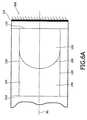
図3は、動作させるためにエレクトロウェッティングの現象を利用する代替の好適な可変焦点レンズ200を図解する。このようなレンズ200を、調節可能なミラー100を形成するために、図2Aに図解した可変レンズ(120、122、130、140、150)として使用することができるであろう。 FIG. 3 illustrates an alternative suitable
そのデバイス200は、第一の流体220及び第二の流体230を含み、それら二つの流体は、不混和性である。第一の流体220は、シリコーン油又はアルカンのような、非導電性の無極性の液体である。第二の流体230は、塩を含有する水の溶液(又は水及びエチレングリコールの混合物)のような、導電性又は有極性の液体である。 The
そのレンズが、配向とは無関係に機能するように、二つの流体の間における重力の効果を最小にするために、二つの流体220、230は、好ましくは、等しい密度を有するように、配置される。二つの流体220、230は、それら二つの流体の間の界面225が、レンズとして作用することになるように、異なる屈折率を有する。 In order to minimize the effect of gravity between the two fluids so that the lens functions independently of orientation, the two
界面225の形状を変動させることは、そのレンズの焦点距離を変動させることになる。界面225の形状は、その流体及びデバイス200の壁の接触角を変えるために、電極260と電極242との間に電圧を印加することによって、エレクトロウェッティングの現象によって、調節される。 Changing the shape of the
そのデバイスを通じた光の透過を可能にするために、少なくとも、そのデバイスの対向する面(図に示された配向で、上部の表面及び下部の表面)は、透明である。この特定の実施形態においては、そのデバイスは、柱体210の形態をとり、且つ、光は、その柱体の透明な末端212、214を通じて入射すると共に射出する。流体220、230は、柱体210によって定義された、密閉された空間内に閉じ込められる。柱体210の内面の一方の末端260は、有極性の流体230を誘引するために、親水性である。柱体210の残り(すなわち、反対の末端、及び内部の側壁)は、疎水性の被覆剤270で被覆される。 At least the opposing faces of the device (upper and lower surfaces in the orientation shown in the figure) are transparent to allow transmission of light through the device. In this particular embodiment, the device takes the form of a
親水性の領域260を、すっかり親水性の材料で形成してもよく、又は、代わりに、親水性の層(たとえば、二酸化ケイ素又はガラス)で被覆してもよい。 The
この特定の実施形態においては、その内面の親水性の領域260は、電極を形成するために、透明な親水性の導電体(たとえば、酸化スズインジウム)によって、完全に覆われる。 In this particular embodiment, the
電圧は、透明な電極260及び三相の線に近接したデバイス200のまわりに広がる環状の電極242によって、有極性の液体230を横切って、可変電圧源240から供給される。可変電圧源240は、DC源として図解されるが、その電圧源は、代わりに、AC源であってもよい。電極242は、有極性の流体230と導電性接触してない。 Voltage is supplied from the
その柱体の内面の一つの領域について親水性であるように、且つ、その内面の残りが、疎水性であるように、配置することによって、この二つの流体の系において、そのデバイスの安定性が、大いに高められることになることは、認識されると思われる。その有極性の流体は、その無極性の流体のみを有することが望まれる、及び、逆もまた同じである、内面のいずれの部分にも付着しないことになる。 The stability of the device in this two-fluid system by placing it so that it is hydrophilic for one region of the inner surface of the column and the rest of the inner surface is hydrophobic However, it will be recognized that it will be greatly enhanced. The polar fluid will not adhere to any part of the inner surface where it is desired to have only the non-polar fluid and vice versa.
この条件が、有極性の流体230が疎水性の被覆剤270の部分と接触することを、禁止しないことは、注意されるべきである。その親水性の層の目的は、その有極性の流体を位置させること、すなわち、その有極性の流体を所望の位置に保つ(且つ、その位置がしばしば少なくとも部分的にその形状を定義する)ことである。このように、相対的に小さい親水性の領域は、この目的に適切なものであってもよい。例えば、有極性の流体をある一定の形状又は位置に保つことが必要である、領域から離れた、あるデバイスの内面の全体が、疎水性であり得るであろう。 It should be noted that this condition does not prohibit the
エレクトロウェッティングを、ある表面における有極性又は導電性の流体の湿潤性を増加させるために、使用することができる。この湿潤性が、初期に小さい(有極性の液体について、これは、通常、疎水性の表面と称される、たとえば、テフロン(登録商標)様の表面)とすれば、電圧を、それをより大きくするために、使用することができる。その湿潤性が、初期に大きい(有極性の液体について、これは、通常、親水性の表面と称される、たとえば、二酸化ケイ素)とすれば、そのとき印加する電圧は、相対的に小さい効果を有することになる。従って、エレクトロウェッティングデバイスにおいて、その三相の線が、初期に、疎水性の層と接触していることは、好ましい。 Electrowetting can be used to increase the wettability of a polar or conductive fluid at a surface. If this wettability is initially small (for polar liquids, this is usually referred to as a hydrophobic surface, eg a Teflon-like surface), the voltage Can be used to enlarge. If the wettability is initially high (for polar liquids, this is usually referred to as a hydrophilic surface, eg silicon dioxide), the applied voltage is then relatively small. Will have. Thus, in an electrowetting device, it is preferred that the three-phase line is initially in contact with the hydrophobic layer.
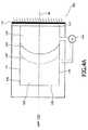
図4Aは、本発明の第二の実施形態と一致した調節可能なミラー300の断面の概略図を図解する。ミラー300は、概して、図2Aに図解されたミラー100に類似すると共に、同一の符号を、類似の構成部品を示唆するために利用する。この特定の実施形態においては、調節可能なミラー300は、流体で満たされたチャンバー125に接続された、且つ、チャンバー125へ及びチャンバー125からある量の一つ以上の流体をポンプで供給するために配置された、ポンプ30をさらに含む。この特定の例において、チャンバー125内における二つの流体130、140の同じ合計の容積を維持するために、ポンプ310は、同時に流体130の容積を増加させると共に流体140の容積を減少させるために(及び、逆もまた同じである)、配置される。その結果は、流体が、追加されると、メニスカス150を、その光軸に沿って移動させることになる、すなわち、余分の流体130が、追加されると、そのとき、そのメニスカスは、位置150’’へ移動してもよい、というものであると思われる。この特定の実施形態において、そのメニスカスの形状は、変えられず、その光軸に沿ったそれの場所のみが、変えられる。 FIG. 4A illustrates a schematic cross-sectional view of an
従って、その結果は、図4Bに示唆したように、そのメニスカス及びその反射面によって提供された等価なミラーの機能の形状は、変えられないが、しかし、そのミラーの機能の場所のみが、その光軸に沿って変えられるというものである。(390)は、そのメニスカスが、位置150にあるときにおける、そのミラーの機能を表し、390’’は、そのミラーの機能が、位置150’’にあることを表す。 Therefore, the result is that, as suggested in FIG. 4B, the shape of the equivalent mirror function provided by the meniscus and the reflective surface cannot be changed, but only the location of the function of the mirror is It can be changed along the optical axis. (390) indicates the function of the mirror when the meniscus is at
様々なタイプのポンプを、ポンプ310として使用してもよい。例えば、国際公開第02/069016号パンフレットは、流体を移動させることができる方法の多くの方式を、たとえば、電気毛管、差圧電気毛管、エレクトロウェッティング、継続的エレクトロウェッティング、電気泳動、電気浸透、誘電泳動、電磁流体力学的ポンピング、熱毛管、熱膨張、誘電ポンピング、又は可変誘電ポンピングを、記述し、それらのいずれも、ポンプ310によって要求されたポンプの作用を提供するために、使用することができるであろう。 Various types of pumps may be used as the
代替の実施形態において、たとえば、その光軸に平行に走る壁の湿潤性を変動させることによって、又は、エレクトロウェッティングの効果を適用することによって、そのメニスカスの位置が、変化すると、そのメニスカスの形状は、変動させられる。 In alternative embodiments, when the position of the meniscus changes, for example, by varying the wettability of a wall running parallel to the optical axis or by applying the effect of electrowetting, The shape is varied.
上記の実施形態においては、より高い屈折率の流体130が、その反射面に隣接していること、及び、メニスカス150が、この流体に関して凸であることを、みてきた。しかしながら、それら二つの流体のいずれかは、より高い屈折率を有することができること、及び、そのメニスカスは、いずれかの流体に関して凹又は凸であり得ることは、認識されると思われる。例えば、図5Aは、無極性の流体140が、より高い屈折率を有すると共に反射面110に隣接している、調節可能なミラー400を図解する。この例では、流体130は、有極性の流体であり、且つ、反射面110に対向した流体チャンバー120、122の表面を形成する、親水性の表面122を介して、位置させられる。 In the above embodiments, it has been seen that the higher
その結果は、メニスカス152が、凹レンズとして作用することになり、且つ、そのメニスカス及びその反射面によって提供された結果として生じる光学的な機能が、凸面のミラー490のものである、というものである。そのメニスカスの曲率が、たとえば152’に、増加させられるとすれば、対応するミラーの機能の曲率は、対応して、減少させられることになる、すなわち、ミラーの機能は、より小さい曲率半径490’を有することになる。 The result is that the
上記の実施形態は、ほんの一例として提供されること、及び、様々な代替物が、本発明の範囲内に属することになることは、認識されると思われる。例えば、上記の実施形態においては、平面の反射面が利用されることが、仮定されてきた。このような平坦な反射面は、反射性に形成することが容易であるという利点を有する。しかしながら、その反射面が、どんな形状のものでも、たとえば、凹、凸、放物面、又は、どんな所望の非球面の形状でも、あり得るであろうことは、認識されると思われる。上記の実施形態においては、その反射面が、その光軸に実質的に垂直であることが、仮定されてきた。しかしながら、
その反射面が、その光軸を横断する(すなわち、それが、その光軸に交差する)限りは、その反射面は、その光軸に対してどんな所望の角度でもあり得ることは、認識されると思われる。例えば、その反射面は、所定の角度でその光軸に交差する平面の表面である得るであろうし、又は、均等に、それは、その光軸に関して傾斜させられた凹面又は凸面であり得るであろう。It will be appreciated that the above embodiments are provided by way of example only and that various alternatives will fall within the scope of the invention. For example, in the above embodiments, it has been assumed that a planar reflective surface is utilized. Such a flat reflecting surface has an advantage that it can be easily formed reflectively. However, it will be appreciated that the reflective surface can be of any shape, for example, concave, convex, parabolic, or any desired aspheric shape. In the above embodiments, it has been assumed that the reflective surface is substantially perpendicular to the optical axis. However,
It will be appreciated that the reflective surface can be at any desired angle with respect to the optical axis as long as the reflective surface crosses the optical axis (ie, it intersects the optical axis). It seems to be that. For example, the reflective surface could be a planar surface that intersects the optical axis at a predetermined angle, or, equally, it could be a concave or convex surface that is tilted with respect to the optical axis. Let's go.
上記の実施形態において、その調節可能なミラーは、二つの流体の間のメニスカス及び単一の反射面によって形成された単一の可変な光学デバイス(たとえば可変レンズ)を含むように、示されてきた。しかしながら、代替の実施形態は、複数の可変な光学デバイス又は複数の反射面を含むことができることは、認識されると思われる。例えば、調節可能なミラーを、可変な光学デバイスの配列(好ましくは、各々の光学デバイスが、その反射面の異なる領域に対応する)を備えた、単一の(相対的に大きい)反射面で形成することができるであろう。 In the above embodiment, the adjustable mirror has been shown to include a single variable optical device (eg, a variable lens) formed by a meniscus between two fluids and a single reflective surface. It was. However, it will be appreciated that alternative embodiments may include multiple variable optical devices or multiple reflective surfaces. For example, the adjustable mirror can be a single (relatively large) reflective surface with an array of variable optical devices (preferably each optical device corresponding to a different area of its reflective surface). Could be formed.
均等に、どんな他の所望の光学構成部品をも、その調節可能なミラーが、所望の光学的な応答を提供するように、その調節可能なミラー内に組み込むことができる。例えば、調節可能なミラー又は回折格子又はさらなるレンズを、そのミラーの所望の用途に依存して、その調節可能なミラー内に組み込むことができるであろう。 Equally, any other desired optical component can be incorporated into the adjustable mirror such that the adjustable mirror provides the desired optical response. For example, an adjustable mirror or diffraction grating or additional lens could be incorporated into the adjustable mirror depending on the desired application of the mirror.
例えば、図6Aは、本発明のさらなる実施形態と一致した調節可能なミラー500を図解する。(たとえば、光軸90を実質的に横断して広がる)非球面レンズ素子510が、形成された有効な調節可能なミラー590が、(例えば、R.Kingslakeによる本“Lens Design Fundamentals”(AcademicPress)の中に記載されているような)マンジャン(Mangin)タイプのものであるように、その光路内に提供される。このレンズのタイプは、反射性の且つ屈折性の部分からなる。その屈折性の部分の材料特性の選択における自由度は、より多くの設計の自由度を許容する。 For example, FIG. 6A illustrates an
上記の実施形態において、そのメニスカス(それら二つの流体の間の界面)は、湾曲したものであり、且つ、その光軸に関して概して対称的であり、且つ、その光軸と交差する点でその光軸に概して垂直であるように、示唆されてきた。しかしながら、そのメニスカスによって実行される所望の光学的な機能に依存して、これらの条件のいずれも、又は、これらの条件の全てを、変化させることができることは、認識されると思われる。 In the above embodiment, the meniscus (the interface between the two fluids) is curved and generally symmetric about the optical axis and the light at a point intersecting the optical axis. It has been suggested to be generally perpendicular to the axis. However, it will be appreciated that any or all of these conditions can be varied depending on the desired optical function performed by the meniscus.
例えば、そのメニスカスは、実質的に平坦な(すなわち、平面の)ものであり得る。そのメニスカスの形状は、その光軸に関して非対称的であり得ると共に、それは、現実には、その光軸に対してある角度で傾斜させられ得る。例えば、このような効果を、そのメニスカスの周辺における異なる点で、異なるエレクトロウェッティングの特性を提供する表面及び/又は電極の構成を使用することによって、達成することができる。このような異なるエレクトロウェッティングの特性は、関連した表面との異なる接触角を経験する、その周辺の異なる部分に帰着することになり、よって、そのメニスカスの全体的な形状を変化させる。均等に、異なるメニスカスの構成を、エレクトロウェッティングを利用することによって、且つ、その光軸に非平行である、そのメニスカスが接触する表面の一つ以上を有することによって、達成することができることは、認識されると思われる。 For example, the meniscus can be substantially flat (ie, planar). The shape of the meniscus can be asymmetric with respect to the optical axis, and in reality it can be tilted at an angle with respect to the optical axis. For example, such an effect can be achieved by using surface and / or electrode configurations that provide different electrowetting properties at different points around the meniscus. Such different electrowetting properties result in different parts of the periphery that experience different contact angles with the associated surface, thus changing the overall shape of the meniscus. Equally, different meniscus configurations can be achieved by utilizing electrowetting and by having one or more surfaces that the meniscus contacts that are non-parallel to the optical axis. Seems to be recognized.
図7は、本発明の別の実施形態と一致した調節可能なミラー600の単純化された断面図を図解する。この特定の実施形態において、側壁120は、側壁120’とは、それら二つの流体に関して異なる湿潤性を有する。湿潤性におけるこの差は、それら側壁の固有の性質のおかげである(表面120、120’が、異なる材料で形成される)か、又は、一方の表面の湿潤性を他方の表面よりも大きい量で変化させるためにエレクトロウェッティングの効果を適用することによってかの、いずれかであり得る。望みであれば、メニスカス154の周辺に接触する側壁の各々の部分を、異なる湿潤性を有するように、配置することができる。 FIG. 7 illustrates a simplified cross-sectional view of an
表面の領域120、120’の湿潤性を適切に調節することによって、そのメニスカスがその表面に接触する接触角を、変えることができ、このように、そのメニスカスの形状を変化させることができる。例えば、メニスカス154は、(少なくとも、考慮された特定の断面に関して)本質的に平面であると共に光軸90に関して特定の角度にあるように示される。望みであれば、エレクトロウェッティングの効果を使用して、その表面の湿潤性を、よって、表面120、120’とのそのメニスカスの接触角を、適切に変えることによって、平面のメニスカス154の角度を、たとえば、メニスカス154’’を形成するために、その光軸に関して異なる角度へ、調節することができる。あるいは、接触角の適切な選択によって、そのメニスカスの形状を、湾曲したメニスカス、すなわち、メニスカス154’を形成するように、調節することができる。その正味の結果は、異なる光学的な機能を提供するために、そのメニスカスの形状又は位置が、変えられるというものであろう。例えば、平面のメニスカス154は、光軸90に沿ってそのメニスカスに入射するビームの経路を屈折させて偏向させる、屈折性のビーム偏向器として作用するであろう。そのメニスカスの位置及び/又は配向を変えることによって、調節可能なミラー600のある範囲の構成に至る、様々な光学的な機能を、実現することができる。 By appropriately adjusting the wettability of the
また、ここに記載された調節可能なミラーを、どんな光学デバイスにも、例えば、(例えば、米国特許第5,880,896号明細書に記載されたような)光走査デバイス内で、又は、適合性のある反射器を提供するために、たとえば、乗り物の前照灯用の反射器の系内で可変な照明系を提供するため、反射器を使用する照明系(その場合には、通常、付加的な光源が提供されるであろう)において、使用することができるであろうということも、認識されると思われる。 Also, the adjustable mirror described herein can be applied to any optical device, eg, in an optical scanning device (eg, as described in US Pat. No. 5,880,896), or To provide a compatible reflector, for example, to provide a variable illumination system within a reflector system for a vehicle headlamp, an illumination system that uses a reflector (in this case, usually It will also be appreciated that an additional light source could be provided) could be used.
レーザー内では、(共振空胴ともまた称される)二つのミラーの共振器が、一般に使用される。それらのミラーは、平面のもの、凹のもの、又は凸のものであり得る。それら二つのミラーの曲率及びその空胴の長さを固定することによって、所望の特性を有する、良好に定義されたガウス(Gaussian)型の共振器のモードを、選択することができる。その共振器に受動的な素子を置くことによって、そのレーザーのモードを、例えば、C.Pare et al,IEEE J.Quantum Electron.28(1994)p355、J.Leger et al,Opt.Lett.19(1994)p108、J.Leger et al,Opt.Lett.19(1994)p1976、S.Makki et al,IEEE J.Electron.35(1999)p1075、J.Leger et al,ODF2000 proceedings p89に記載されているように、もたらすことができる。 Within a laser, a two-mirror resonator (also referred to as a resonant cavity) is commonly used. The mirrors can be planar, concave or convex. By fixing the curvature of the two mirrors and the cavity length, a well-defined Gaussian-type resonator mode with the desired characteristics can be selected. By placing passive elements in the resonator, the mode of the laser is changed, for example, C.I. Pare et al, IEEE J. et al. Quantum Electron. 28 (1994) p355, J. MoI. Leger et al, Opt. Lett. 19 (1994) p108, J. MoI. Leger et al, Opt. Lett. 19 (1994) p1976, S.A. Makki et al, IEEE J. et al. Electron. 35 (1999) p1075, J. MoI. As described in Leger et al, ODF2000 processes p89.
本発明を、このような共振器の設計の余地を増加させるために、その共振器のモードを能動的に変えることによって、使用することができる。その共振器のモードを変えるために、それらミラーの少なくとも一つの曲率が、調節される。これを、本発明と一致したミラーを使用することによって、達成することができる。 The present invention can be used by actively changing the mode of the resonator in order to increase the room for designing such a resonator. In order to change the mode of the resonator, at least one curvature of the mirrors is adjusted. This can be achieved by using a mirror consistent with the present invention.
図8は、第一の及び第二のミラー710、720を含むレーザーの空胴700を図解する。ミラー710、720の少なくとも一方は、調節可能なミラーである。レーザー光の出力730を可能にするために、ミラー720は、半透明である。ゲイン媒体740は、典型的には、二つのミラー710、720の間に存在する。それらミラーの一つ以上の曲率は、所望の光学モードを提供するために、調節される。そのモードにおけるその曲率の効果は、H.Kogelnik and T.Li,Appl.Opt.5,(1966)pp1550−1567の“Laser beams and resonators”に、及び、“Lasers”,A.E.Siegman,University Science Books,Mill Valley,California Chapter 19の本にもまた、広く記載されてきた。Chapter 19には、八つの異なる共振器のタイプ、(1)対称的な共振器、(2)半対称的な共振器、(3)対称的な共焦点の共振器、(4)長い半径の(ほぼ平面の)共振器、(5)ほぼ同心の共振器、(6)半球型の共振器、(7)凹凸の共振器、及び(8)不安定な共焦点の共振器が、記載されている。これらのタイプの各々は、それら自体の特性を有する。調節可能なミラーにおけるそれら二つの流体の間のメニスカスの曲率又は位置を変えることによって、空胴600を、所望の共振のモードの間で切り替えることができる。 FIG. 8 illustrates a
二つの流体の間のメニスカス及び反射面によって形成された可変な光学デバイス(たとえば、可変レンズ又は可変ビーム偏向器)を含む調節可能なミラーを提供することによって、本発明が、光路が機械的疲労を欠点としてもたない調節可能なミラーを提供することは、認識されると思われる。さらに、そのデバイスを、コスト効率良く作ることができると共にそれを容易に制御することができる。 By providing an adjustable mirror that includes a variable optical device (eg, a variable lens or a variable beam deflector) formed by a meniscus and a reflective surface between two fluids, the present invention makes it possible for the optical path to be mechanically fatigued. It would be appreciated to provide an adjustable mirror that does not suffer from the disadvantages. Furthermore, the device can be made cost-effectively and easily controlled.
Claims (10)
Translated fromJapanese光軸を横断して広がるメニスカスにわたって接触している第一の流体及び第二の流体
を含み、
該流体は、実質的に不混和性であると共に異なる屈折率を有し、
当該調節可能なミラーは、
該光軸を横断して広がる反射面、並びに
該メニスカスの形状及び位置の少なくとも一つを制御可能に変えるために配置されたメニスカス調節器
を含む、調節可能なミラー。An adjustable mirror,
Comprising a first fluid and a second fluid in contact across a meniscus extending across the optical axis;
The fluid is substantially immiscible and has a different refractive index;
The adjustable mirror is
An adjustable mirror comprising a reflective surface extending across the optical axis and a meniscus adjuster arranged to controllably change at least one of the shape and position of the meniscus.
光軸を横断して広がるメニスカスにわたって接触している第一の流体及び第二の流体
を含み、
該流体は、実質的に不混和性であると共に異なる屈折率を有し、
当該光学デバイスは、
該光軸を横断して広がる反射面、並びに、
該メニスカスの形状及び位置の少なくとも一つを制御可能に変えるために配置されたメニスカス調節器
を含む、光学デバイス。An optical device,
Comprising a first fluid and a second fluid in contact across a meniscus extending across the optical axis;
The fluid is substantially immiscible and has a different refractive index;
The optical device is
A reflective surface extending across the optical axis, and
An optical device comprising a meniscus adjuster arranged to controllably change at least one of the shape and position of the meniscus.
当該デバイスは、電磁放射を放出するために配置された光源をさらに含む、請求項5に記載の光学デバイス。The device is an illumination system that provides a directed beam of light;
The optical device of claim 5, further comprising a light source arranged to emit electromagnetic radiation.
該空胴は、第二のミラーを含む、請求項5に記載の光学デバイス。The optical device includes a laser cavity,
The optical device of claim 5, wherein the cavity includes a second mirror.
当該方法は、
光軸を実質的に横断して広がるメニスカスにわたって接触している第一の流体及び第二の流体を提供するステップを含み、
該流体は、実質的に不混和性であると共に異なる屈折率を有し、
当該方法は、
該光軸を横断して広がる反射面を提供するステップ、並びに
該メニスカスの形状及び位置の少なくとも一つを変えるために配置されたメニスカス調節器を提供するステップ
を含む、調節可能なミラーを製造する方法。A method of manufacturing an adjustable mirror, comprising:
The method is
Providing a first fluid and a second fluid in contact over a meniscus extending substantially across the optical axis;
The fluid is substantially immiscible and has a different refractive index;
The method is
Providing an adjustable mirror comprising providing a reflective surface extending across the optical axis and providing a meniscus adjuster arranged to change at least one of the shape and position of the meniscus Method.
該光学デバイスは、
光軸を横断して広がるメニスカスにわたって接触している第一の流体及び第二の流体
を含み、
該流体は、実質的に不混和性であると共に異なる屈折率を有し、
該光学デバイスは、
該光軸を横断して広がる反射面
を含み、
当該方法は、ミラーが、所望の反射の特性を提供するように、該メニスカスの形状及び位置の少なくとも一つを制御可能に変えることを含む、
光学デバイスを動作させる方法。A method of operating an optical device, comprising:
The optical device is
Comprising a first fluid and a second fluid in contact across a meniscus extending across the optical axis;
The fluid is substantially immiscible and has a different refractive index;
The optical device is
A reflective surface extending across the optical axis,
The method includes controllably changing at least one of the shape and position of the meniscus so that a mirror provides a desired reflection characteristic.
A method of operating an optical device.
Applications Claiming Priority (2)
| Application Number | Priority Date | Filing Date | Title |
|---|---|---|---|
| EP03101336 | 2003-05-14 | ||
| PCT/IB2004/050619WO2004102251A1 (en) | 2003-05-14 | 2004-05-10 | Adjustable mirror |
Publications (1)
| Publication Number | Publication Date |
|---|---|
| JP2007503025Atrue JP2007503025A (en) | 2007-02-15 |
Family
ID=33442821
Family Applications (1)
| Application Number | Title | Priority Date | Filing Date |
|---|---|---|---|
| JP2006530788AWithdrawnJP2007503025A (en) | 2003-05-14 | 2004-05-10 | Adjustable mirror |
Country Status (6)
| Country | Link |
|---|---|
| US (1) | US7385755B2 (en) |
| EP (1) | EP1625439A1 (en) |
| JP (1) | JP2007503025A (en) |
| KR (1) | KR20060014398A (en) |
| CN (1) | CN100476497C (en) |
| WO (1) | WO2004102251A1 (en) |
Families Citing this family (18)
| Publication number | Priority date | Publication date | Assignee | Title |
|---|---|---|---|---|
| EP1625442B1 (en)* | 2003-05-14 | 2012-08-22 | Koninklijke Philips Electronics N.V. | Variable shape lens |
| US7613388B2 (en) | 2004-03-31 | 2009-11-03 | Koninklijke Philips Electronics N.V. | Focusing lens with electrowetting based macro switch |
| KR20060134153A (en) | 2004-04-13 | 2006-12-27 | 코닌클리케 필립스 일렉트로닉스 엔.브이. | Autostereoscopic Display Device |
| KR100541820B1 (en)* | 2004-05-28 | 2006-01-11 | 삼성전자주식회사 | Particle Detection Device for Semiconductor Device Manufacturing |
| KR20070120537A (en) | 2005-04-22 | 2007-12-24 | 코닌클리케 필립스 일렉트로닉스 엔.브이. | Varifocal lens |
| SG142292A1 (en) | 2006-11-07 | 2008-05-28 | Agency Science Tech & Res | Device and method to realize a light processor |
| WO2008097440A2 (en)* | 2007-02-05 | 2008-08-14 | Xtreme Energetics Inc. | Electro-wetting optical light steering |
| KR101593186B1 (en)* | 2009-08-13 | 2016-02-12 | 삼성디스플레이 주식회사 | A lens array and a three-dimensional display device including the same |
| WO2011054392A1 (en)* | 2009-11-06 | 2011-05-12 | Nokia Siemens Networks Oy | An electrically controllable collimator in a laser resonator |
| DE102010009048A1 (en)* | 2010-02-23 | 2011-08-25 | LPKF Laser & Electronics AG, 30827 | laser assembly |
| DE102010010328A1 (en)* | 2010-03-04 | 2011-09-29 | Jos. Schneider Optische Werke Gmbh | Planar imaging system |
| JP2012133026A (en)* | 2010-12-20 | 2012-07-12 | Canon Inc | Focal length variable prism and prism optical system using the same |
| WO2015022027A1 (en)* | 2013-08-14 | 2015-02-19 | Albert-Ludwigs-Universität Freiburg | Fluidically controlled optical router |
| JP2017227760A (en)* | 2016-06-22 | 2017-12-28 | ソニー株式会社 | Liquid lens and method for driving the same, imaging device, and display device |
| FR3077686B1 (en)* | 2018-02-05 | 2020-09-25 | Commissariat Energie Atomique | ELEMENT OF AN OPTICAL SYSTEM, TO RECEIVE A FUNCTIONAL FLUID UNDER PRESSURE. |
| KR102132210B1 (en)* | 2018-10-23 | 2020-07-09 | 주식회사 하이로닉 | Laser system |
| US11881676B2 (en)* | 2019-01-31 | 2024-01-23 | L3Harris Technologies, Inc. | End-pumped Q-switched laser |
| WO2023025693A2 (en)* | 2021-08-26 | 2023-03-02 | Jt International Sa | Aerosol generating device comprising an optical sensor |
Family Cites Families (18)
| Publication number | Priority date | Publication date | Assignee | Title |
|---|---|---|---|---|
| US4289379A (en) | 1977-04-27 | 1981-09-15 | Quantel S.A. | Optical system having a variable focal length |
| US4583824A (en)* | 1984-10-10 | 1986-04-22 | University Of Rochester | Electrocapillary devices |
| GB2183059B (en) | 1985-11-05 | 1989-09-27 | Michel Treisman | Suspension system for a flexible optical membrane |
| US4951285A (en)* | 1988-07-05 | 1990-08-21 | Spectra-Physics | Laser with adjustable mirror for mode control |
| JP3420894B2 (en) | 1996-08-09 | 2003-06-30 | シャープ株式会社 | Deformable mirror |
| JP3644145B2 (en)* | 1996-08-21 | 2005-04-27 | 三菱電機株式会社 | Laser equipment |
| US6302542B1 (en) | 1996-08-23 | 2001-10-16 | Che-Chih Tsao | Moving screen projection technique for volumetric three-dimensional display |
| JPH10188319A (en) | 1996-12-26 | 1998-07-21 | Sharp Corp | Deformable mirror and optical recording / reproducing apparatus using the deformable mirror |
| DE19710668A1 (en) | 1997-03-14 | 1998-09-17 | Robert Seidel | Variable lens system e.g. for endoscope zoom lens |
| JPH1172605A (en) | 1997-08-29 | 1999-03-16 | Ishikawajima Harima Heavy Ind Co Ltd | Variable curvature mirror and lens |
| FR2769375B1 (en)* | 1997-10-08 | 2001-01-19 | Univ Joseph Fourier | VARIABLE FOCAL LENS |
| US6449081B1 (en)* | 1999-06-16 | 2002-09-10 | Canon Kabushiki Kaisha | Optical element and optical device having it |
| US6538748B1 (en)* | 2000-04-14 | 2003-03-25 | Agilent Technologies, Inc | Tunable Fabry-Perot filters and lasers utilizing feedback to reduce frequency noise |
| JP2001318326A (en) | 2000-05-12 | 2001-11-16 | Canon Inc | Optical element and two-dimensional image display element constituted by the optical element |
| US20020156221A1 (en) | 2001-02-20 | 2002-10-24 | Meyer Gerald Wayne | High solids acrylic resin |
| US7016560B2 (en)* | 2001-02-28 | 2006-03-21 | Lightwave Microsystems Corporation | Microfluidic control for waveguide optical switches, variable attenuators, and other optical devices |
| US6949176B2 (en) | 2001-02-28 | 2005-09-27 | Lightwave Microsystems Corporation | Microfluidic control using dielectric pumping |
| CN1268979C (en)* | 2001-06-05 | 2006-08-09 | 皇家菲利浦电子有限公司 | Display device based on frustrated total internal reflection |
- 2004
- 2004-05-10EPEP04731984Apatent/EP1625439A1/ennot_activeWithdrawn
- 2004-05-10KRKR1020057021472Apatent/KR20060014398A/ennot_activeCeased
- 2004-05-10USUS10/556,246patent/US7385755B2/ennot_activeExpired - Fee Related
- 2004-05-10WOPCT/IB2004/050619patent/WO2004102251A1/enactiveApplication Filing
- 2004-05-10JPJP2006530788Apatent/JP2007503025A/ennot_activeWithdrawn
- 2004-05-10CNCNB2004800127990Apatent/CN100476497C/ennot_activeExpired - Fee Related
Also Published As
| Publication number | Publication date |
|---|---|
| CN100476497C (en) | 2009-04-08 |
| US7385755B2 (en) | 2008-06-10 |
| CN1788223A (en) | 2006-06-14 |
| KR20060014398A (en) | 2006-02-15 |
| EP1625439A1 (en) | 2006-02-15 |
| WO2004102251A1 (en) | 2004-11-25 |
| US20060262433A1 (en) | 2006-11-23 |
Similar Documents
| Publication | Publication Date | Title |
|---|---|---|
| CN100476497C (en) | Tunable mirror, optical device and manufacturing method thereof | |
| CN100460923C (en) | Variable reflector | |
| EP1623264B1 (en) | Switchable optical element using surfactants | |
| KR101088655B1 (en) | Variable lens | |
| JP4388954B2 (en) | Improvements in and relating to fluid-filled devices | |
| KR101101400B1 (en) | Electrowetting lens | |
| KR101098309B1 (en) | Variable shape lens | |
| CN100373174C (en) | Variable lens | |
| US20050275927A1 (en) | Variable focal length lens comprising micromirrors with two degrees of freedom rotation | |
| KR20070035089A (en) | Variable Focal Length Lenses and Lens Arrays with Discontinuously Controlled Micromirrors | |
| JP2004280105A (en) | Micro-mirror element extending light angle | |
| EP1870742B1 (en) | Tri-liquid lens | |
| JP4777624B2 (en) | Optical beam splitter with electrowetting action | |
| EP1894041A1 (en) | Variable fluid lens having two menisci | |
| JP2007531051A (en) | Ghost image removal with image sensor using variable focus lens | |
| CN105676448A (en) | Focusing micro-mirror and focusing device | |
| CN114740555B (en) | A multifunctional liquid lens with adjustable surface shape and aperture | |
| Clement et al. | Focal point control using an EWOD-based tuneable Fresnel lens |
Legal Events
| Date | Code | Title | Description |
|---|---|---|---|
| A621 | Written request for application examination | Free format text:JAPANESE INTERMEDIATE CODE: A621 Effective date:20070507 | |
| A761 | Written withdrawal of application | Free format text:JAPANESE INTERMEDIATE CODE: A761 Effective date:20091215 |