JP2007502683A - Display system - Google Patents
Display systemDownload PDFInfo
- Publication number
- JP2007502683A JP2007502683AJP2006529887AJP2006529887AJP2007502683AJP 2007502683 AJP2007502683 AJP 2007502683AJP 2006529887 AJP2006529887 AJP 2006529887AJP 2006529887 AJP2006529887 AJP 2006529887AJP 2007502683 AJP2007502683 AJP 2007502683A
- Authority
- JP
- Japan
- Prior art keywords
- display
- event
- elapsed time
- display mode
- modes
- Prior art date
- Legal status (The legal status is an assumption and is not a legal conclusion. Google has not performed a legal analysis and makes no representation as to the accuracy of the status listed.)
- Granted
Links
- 238000001514detection methodMethods0.000claimsabstractdescription25
- 230000004044responseEffects0.000claimsabstractdescription14
- 239000003814drugSubstances0.000claimsdescription87
- 229940079593drugDrugs0.000claimsdescription83
- 230000001419dependent effectEffects0.000claimsdescription2
- 210000000214mouthAnatomy0.000claimsdescription2
- 210000003928nasal cavityAnatomy0.000claimsdescription2
- -1cromoglycate (egChemical compound0.000description13
- 230000007246mechanismEffects0.000description11
- 239000000546pharmaceutical excipientSubstances0.000description10
- 239000002585baseSubstances0.000description9
- 230000002028prematureEffects0.000description8
- 239000002245particleSubstances0.000description7
- GIIZNNXWQWCKIB-UHFFFAOYSA-NSereventChemical compoundC1=C(O)C(CO)=CC(C(O)CNCCCCCCOCCCCC=2C=CC=CC=2)=C1GIIZNNXWQWCKIB-UHFFFAOYSA-N0.000description6
- 238000004891communicationMethods0.000description6
- 238000000034methodMethods0.000description6
- 230000005855radiationEffects0.000description6
- 238000010586diagramMethods0.000description5
- 239000000843powderSubstances0.000description5
- 210000003813thumbAnatomy0.000description5
- NDAUXUAQIAJITI-UHFFFAOYSA-NalbuterolChemical compoundCC(C)(C)NCC(O)C1=CC=C(O)C(CO)=C1NDAUXUAQIAJITI-UHFFFAOYSA-N0.000description4
- 230000008901benefitEffects0.000description4
- 238000009472formulationMethods0.000description4
- 239000000203mixtureSubstances0.000description4
- 229960002052salbutamolDrugs0.000description4
- 229960004017salmeterolDrugs0.000description4
- 150000003839saltsChemical class0.000description4
- VZCYOOQTPOCHFL-UHFFFAOYSA-Ntrans-butenedioic acidNatural productsOC(=O)C=CC(O)=OVZCYOOQTPOCHFL-UHFFFAOYSA-N0.000description4
- 238000011282treatmentMethods0.000description4
- 238000004804windingMethods0.000description4
- VOVIALXJUBGFJZ-KWVAZRHASA-NBudesonideChemical compoundC1CC2=CC(=O)C=C[C@]2(C)[C@@H]2[C@@H]1[C@@H]1C[C@H]3OC(CCC)O[C@@]3(C(=O)CO)[C@@]1(C)C[C@@H]2OVOVIALXJUBGFJZ-KWVAZRHASA-N0.000description3
- VZCYOOQTPOCHFL-OWOJBTEDSA-NFumaric acidChemical compoundOC(=O)\C=C\C(O)=OVZCYOOQTPOCHFL-OWOJBTEDSA-N0.000description3
- GUBGYTABKSRVRQ-QKKXKWKRSA-NLactoseNatural productsOC[C@H]1O[C@@H](O[C@H]2[C@H](O)[C@@H](O)C(O)O[C@@H]2CO)[C@H](O)[C@@H](O)[C@H]1OGUBGYTABKSRVRQ-QKKXKWKRSA-N0.000description3
- XBDQKXXYIPTUBI-UHFFFAOYSA-MPropionateChemical compoundCCC([O-])=OXBDQKXXYIPTUBI-UHFFFAOYSA-M0.000description3
- QAOWNCQODCNURD-UHFFFAOYSA-LSulfateChemical compound[O-]S([O-])(=O)=OQAOWNCQODCNURD-UHFFFAOYSA-L0.000description3
- 229940092705beclomethasoneDrugs0.000description3
- 229960004436budesonideDrugs0.000description3
- 239000003795chemical substances by applicationSubstances0.000description3
- 150000002148estersChemical class0.000description3
- 229960002848formoterolDrugs0.000description3
- BPZSYCZIITTYBL-UHFFFAOYSA-NformoterolChemical compoundC1=CC(OC)=CC=C1CC(C)NCC(O)C1=CC=C(O)C(NC=O)=C1BPZSYCZIITTYBL-UHFFFAOYSA-N0.000description3
- 239000008101lactoseSubstances0.000description3
- 208000024891symptomDiseases0.000description3
- KWGRBVOPPLSCSI-WPRPVWTQSA-N(-)-ephedrineChemical compoundCN[C@@H](C)[C@H](O)C1=CC=CC=C1KWGRBVOPPLSCSI-WPRPVWTQSA-N0.000description2
- VTYYLEPIZMXCLO-UHFFFAOYSA-LCalcium carbonateChemical compound[Ca+2].[O-]C([O-])=OVTYYLEPIZMXCLO-UHFFFAOYSA-L0.000description2
- 125000002066L-histidyl groupChemical group[H]N1C([H])=NC(C([H])([H])[C@](C(=O)[*])([H])N([H])[H])=C1[H]0.000description2
- FAPWRFPIFSIZLT-UHFFFAOYSA-MSodium chlorideChemical compound[Na+].[Cl-]FAPWRFPIFSIZLT-UHFFFAOYSA-M0.000description2
- 239000002253acidSubstances0.000description2
- OIRDTQYFTABQOQ-KQYNXXCUSA-NadenosineChemical compoundC1=NC=2C(N)=NC=NC=2N1[C@@H]1O[C@H](CO)[C@@H](O)[C@H]1OOIRDTQYFTABQOQ-KQYNXXCUSA-N0.000description2
- UCTWMZQNUQWSLP-UHFFFAOYSA-NadrenalineChemical compoundCNCC(O)C1=CC=C(O)C(O)=C1UCTWMZQNUQWSLP-UHFFFAOYSA-N0.000description2
- NBMKJKDGKREAPL-DVTGEIKXSA-NbeclomethasoneChemical compoundC1CC2=CC(=O)C=C[C@]2(C)[C@]2(Cl)[C@@H]1[C@@H]1C[C@H](C)[C@@](C(=O)CO)(O)[C@@]1(C)C[C@@H]2ONBMKJKDGKREAPL-DVTGEIKXSA-N0.000description2
- 238000003795desorptionMethods0.000description2
- 230000000694effectsEffects0.000description2
- 210000003811fingerAnatomy0.000description2
- 229960002714fluticasoneDrugs0.000description2
- 229960000289fluticasone propionateDrugs0.000description2
- WMWTYOKRWGGJOA-CENSZEJFSA-Nfluticasone propionateChemical compoundC1([C@@H](F)C2)=CC(=O)C=C[C@]1(C)[C@]1(F)[C@@H]2[C@@H]2C[C@@H](C)[C@@](C(=O)SCF)(OC(=O)CC)[C@@]2(C)C[C@@H]1OWMWTYOKRWGGJOA-CENSZEJFSA-N0.000description2
- 239000012458free baseSubstances0.000description2
- JYGXADMDTFJGBT-VWUMJDOOSA-NhydrocortisoneChemical compoundO=C1CC[C@]2(C)[C@H]3[C@@H](O)C[C@](C)([C@@](CC4)(O)C(=O)CO)[C@@H]4[C@@H]3CCC2=C1JYGXADMDTFJGBT-VWUMJDOOSA-N0.000description2
- NOESYZHRGYRDHS-UHFFFAOYSA-NinsulinChemical compoundN1C(=O)C(NC(=O)C(CCC(N)=O)NC(=O)C(CCC(O)=O)NC(=O)C(C(C)C)NC(=O)C(NC(=O)CN)C(C)CC)CSSCC(C(NC(CO)C(=O)NC(CC(C)C)C(=O)NC(CC=2C=CC(O)=CC=2)C(=O)NC(CCC(N)=O)C(=O)NC(CC(C)C)C(=O)NC(CCC(O)=O)C(=O)NC(CC(N)=O)C(=O)NC(CC=2C=CC(O)=CC=2)C(=O)NC(CSSCC(NC(=O)C(C(C)C)NC(=O)C(CC(C)C)NC(=O)C(CC=2C=CC(O)=CC=2)NC(=O)C(CC(C)C)NC(=O)C(C)NC(=O)C(CCC(O)=O)NC(=O)C(C(C)C)NC(=O)C(CC(C)C)NC(=O)C(CC=2NC=NC=2)NC(=O)C(CO)NC(=O)CNC2=O)C(=O)NCC(=O)NC(CCC(O)=O)C(=O)NC(CCCNC(N)=N)C(=O)NCC(=O)NC(CC=3C=CC=CC=3)C(=O)NC(CC=3C=CC=CC=3)C(=O)NC(CC=3C=CC(O)=CC=3)C(=O)NC(C(C)O)C(=O)N3C(CCC3)C(=O)NC(CCCCN)C(=O)NC(C)C(O)=O)C(=O)NC(CC(N)=O)C(O)=O)=O)NC(=O)C(C(C)CC)NC(=O)C(CO)NC(=O)C(C(C)O)NC(=O)C1CSSCC2NC(=O)C(CC(C)C)NC(=O)C(NC(=O)C(CCC(N)=O)NC(=O)C(CC(N)=O)NC(=O)C(NC(=O)C(N)CC=1C=CC=CC=1)C(C)C)CC1=CN=CN1NOESYZHRGYRDHS-UHFFFAOYSA-N0.000description2
- BQJCRHHNABKAKU-KBQPJGBKSA-NmorphineChemical compoundO([C@H]1[C@H](C=C[C@H]23)O)C4=C5[C@@]12CCN(C)[C@@H]3CC5=CC=C4OBQJCRHHNABKAKU-KBQPJGBKSA-N0.000description2
- 125000002924primary amino groupChemical group[H]N([H])*0.000description2
- 229960005018salmeterol xinafoateDrugs0.000description2
- 159000000000sodium saltsChemical class0.000description2
- 239000012453solvateSubstances0.000description2
- 230000003068static effectEffects0.000description2
- UCSJYZPVAKXKNQ-HZYVHMACSA-NstreptomycinChemical compoundCN[C@H]1[C@H](O)[C@@H](O)[C@H](CO)O[C@H]1O[C@@H]1[C@](C=O)(O)[C@H](C)O[C@H]1O[C@@H]1[C@@H](NC(N)=N)[C@H](O)[C@@H](NC(N)=N)[C@H](O)[C@H]1OUCSJYZPVAKXKNQ-HZYVHMACSA-N0.000description2
- ZFXYFBGIUFBOJW-UHFFFAOYSA-NtheophyllineChemical compoundO=C1N(C)C(=O)N(C)C2=C1NC=N2ZFXYFBGIUFBOJW-UHFFFAOYSA-N0.000description2
- 229950000339xinafoateDrugs0.000description2
- JWZZKOKVBUJMES-UHFFFAOYSA-N(+-)-IsoprenalineChemical compoundCC(C)NCC(O)C1=CC=C(O)C(O)=C1JWZZKOKVBUJMES-UHFFFAOYSA-N0.000description1
- XWTYSIMOBUGWOL-UHFFFAOYSA-N(+-)-TerbutalineChemical compoundCC(C)(C)NCC(O)C1=CC(O)=CC(O)=C1XWTYSIMOBUGWOL-UHFFFAOYSA-N0.000description1
- AKNNEGZIBPJZJG-MSOLQXFVSA-N(-)-noscapineChemical compoundCN1CCC2=CC=3OCOC=3C(OC)=C2[C@@H]1[C@@H]1C2=CC=C(OC)C(OC)=C2C(=O)O1AKNNEGZIBPJZJG-MSOLQXFVSA-N0.000description1
- WRRSFOZOETZUPG-FFHNEAJVSA-N(4r,4ar,7s,7ar,12bs)-9-methoxy-3-methyl-2,4,4a,7,7a,13-hexahydro-1h-4,12-methanobenzofuro[3,2-e]isoquinoline-7-ol;hydrateChemical compoundO.C([C@H]1[C@H](N(CC[C@@]112)C)C3)=C[C@H](O)[C@@H]1OC1=C2C3=CC=C1OCWRRSFOZOETZUPG-FFHNEAJVSA-N0.000description1
- FUFLCEKSBBHCMO-UHFFFAOYSA-N11-dehydrocorticosteroneNatural productsO=C1CCC2(C)C3C(=O)CC(C)(C(CC4)C(=O)CO)C4C3CCC2=C1FUFLCEKSBBHCMO-UHFFFAOYSA-N0.000description1
- 1250000059752-phenylethyloxy groupChemical group0.000description1
- PVXFCOPBOYHONF-UHFFFAOYSA-N3-ethyl-1,3-benzothiazol-2-oneChemical compoundC1=CC=C2SC(=O)N(CC)C2=C1PVXFCOPBOYHONF-UHFFFAOYSA-N0.000description1
- LSLYOANBFKQKPT-DIFFPNOSSA-N5-[(1r)-1-hydroxy-2-[[(2r)-1-(4-hydroxyphenyl)propan-2-yl]amino]ethyl]benzene-1,3-diolChemical compoundC([C@@H](C)NC[C@H](O)C=1C=C(O)C=C(O)C=1)C1=CC=C(O)C=C1LSLYOANBFKQKPT-DIFFPNOSSA-N0.000description1
- QTBSBXVTEAMEQO-UHFFFAOYSA-MAcetateChemical compoundCC([O-])=OQTBSBXVTEAMEQO-UHFFFAOYSA-M0.000description1
- GUBGYTABKSRVRQ-XLOQQCSPSA-NAlpha-LactoseChemical compoundO[C@@H]1[C@@H](O)[C@@H](O)[C@@H](CO)O[C@H]1O[C@@H]1[C@@H](CO)O[C@H](O)[C@H](O)[C@H]1OGUBGYTABKSRVRQ-XLOQQCSPSA-N0.000description1
- 206010002383Angina PectorisDiseases0.000description1
- 229930003347AtropineNatural products0.000description1
- CPELXLSAUQHCOX-UHFFFAOYSA-MBromideChemical compound[Br-]CPELXLSAUQHCOX-UHFFFAOYSA-M0.000description1
- 239000002126C01EB10 - AdenosineSubstances0.000description1
- QWOJMRHUQHTCJG-UHFFFAOYSA-NCC([CH2-])=OChemical compoundCC([CH2-])=OQWOJMRHUQHTCJG-UHFFFAOYSA-N0.000description1
- 229930186147CephalosporinNatural products0.000description1
- 208000006545Chronic Obstructive Pulmonary DiseaseDiseases0.000description1
- LUKZNWIVRBCLON-GXOBDPJESA-NCiclesonideChemical compoundC1([C@H]2O[C@@]3([C@H](O2)C[C@@H]2[C@@]3(C[C@H](O)[C@@H]3[C@@]4(C)C=CC(=O)C=C4CC[C@H]32)C)C(=O)COC(=O)C(C)C)CCCCC1LUKZNWIVRBCLON-GXOBDPJESA-N0.000description1
- MFYSYFVPBJMHGN-ZPOLXVRWSA-NCortisoneChemical compoundO=C1CC[C@]2(C)[C@H]3C(=O)C[C@](C)([C@@](CC4)(O)C(=O)CO)[C@@H]4[C@@H]3CCC2=C1MFYSYFVPBJMHGN-ZPOLXVRWSA-N0.000description1
- MFYSYFVPBJMHGN-UHFFFAOYSA-NCortisoneNatural productsO=C1CCC2(C)C3C(=O)CC(C)(C(CC4)(O)C(=O)CO)C4C3CCC2=C1MFYSYFVPBJMHGN-UHFFFAOYSA-N0.000description1
- FBPFZTCFMRRESA-KVTDHHQDSA-ND-MannitolChemical compoundOC[C@@H](O)[C@@H](O)[C@H](O)[C@H](O)COFBPFZTCFMRRESA-KVTDHHQDSA-N0.000description1
- IJVCSMSMFSCRME-KBQPJGBKSA-NDihydromorphineChemical compoundO([C@H]1[C@H](CC[C@H]23)O)C4=C5[C@@]12CCN(C)[C@@H]3CC5=CC=C4OIJVCSMSMFSCRME-KBQPJGBKSA-N0.000description1
- WQZGKKKJIJFFOK-GASJEMHNSA-NGlucoseNatural productsOC[C@H]1OC(O)[C@H](O)[C@@H](O)[C@@H]1OWQZGKKKJIJFFOK-GASJEMHNSA-N0.000description1
- VEXZGXHMUGYJMC-UHFFFAOYSA-NHydrochloric acidChemical compoundClVEXZGXHMUGYJMC-UHFFFAOYSA-N0.000description1
- CPELXLSAUQHCOX-UHFFFAOYSA-NHydrogen bromideChemical compoundBrCPELXLSAUQHCOX-UHFFFAOYSA-N0.000description1
- RKUNBYITZUJHSG-UHFFFAOYSA-NHyosciamin-hydrochloridNatural productsCN1C(C2)CCC1CC2OC(=O)C(CO)C1=CC=CC=C1RKUNBYITZUJHSG-UHFFFAOYSA-N0.000description1
- 102000004877InsulinHuman genes0.000description1
- 108090001061InsulinProteins0.000description1
- HUYWAWARQUIQLE-UHFFFAOYSA-NIsoetharineChemical compoundCC(C)NC(CC)C(O)C1=CC=C(O)C(O)=C1HUYWAWARQUIQLE-UHFFFAOYSA-N0.000description1
- ZCVMWBYGMWKGHF-UHFFFAOYSA-NKetotifeneChemical compoundC1CN(C)CCC1=C1C2=CC=CC=C2CC(=O)C2=C1C=CS2ZCVMWBYGMWKGHF-UHFFFAOYSA-N0.000description1
- KDXKERNSBIXSRK-UHFFFAOYSA-NLysineNatural productsNCCCCC(N)C(O)=OKDXKERNSBIXSRK-UHFFFAOYSA-N0.000description1
- 239000004472LysineSubstances0.000description1
- 229920002774MaltodextrinPolymers0.000description1
- 229930195725MannitolNatural products0.000description1
- 229930182555PenicillinNatural products0.000description1
- JGSARLDLIJGVTE-MBNYWOFBSA-NPenicillin GChemical compoundN([C@H]1[C@H]2SC([C@@H](N2C1=O)C(O)=O)(C)C)C(=O)CC1=CC=CC=C1JGSARLDLIJGVTE-MBNYWOFBSA-N0.000description1
- 229920002472StarchPolymers0.000description1
- 239000004098TetracyclineSubstances0.000description1
- 239000004480active ingredientSubstances0.000description1
- 239000013543active substanceSubstances0.000description1
- 229960005305adenosineDrugs0.000description1
- 239000000556agonistSubstances0.000description1
- 229940057282albuterol sulfateDrugs0.000description1
- BNPSSFBOAGDEEL-UHFFFAOYSA-Nalbuterol sulfateChemical compoundOS(O)(=O)=O.CC(C)(C)NCC(O)C1=CC=C(O)C(CO)=C1.CC(C)(C)NCC(O)C1=CC=C(O)C(CO)=C1BNPSSFBOAGDEEL-UHFFFAOYSA-N0.000description1
- 229910052783alkali metalInorganic materials0.000description1
- 150000001340alkali metalsChemical class0.000description1
- 125000000217alkyl groupChemical group0.000description1
- AKNNEGZIBPJZJG-UHFFFAOYSA-Nalpha-noscapineNatural productsCN1CCC2=CC=3OCOC=3C(OC)=C2C1C1C2=CC=C(OC)C(OC)=C2C(=O)O1AKNNEGZIBPJZJG-UHFFFAOYSA-N0.000description1
- XSDQTOBWRPYKKA-UHFFFAOYSA-NamilorideChemical compoundNC(=N)NC(=O)C1=NC(Cl)=C(N)N=C1NXSDQTOBWRPYKKA-UHFFFAOYSA-N0.000description1
- 229960002576amilorideDrugs0.000description1
- 150000001413amino acidsChemical class0.000description1
- 229960003556aminophyllineDrugs0.000description1
- FQPFAHBPWDRTLU-UHFFFAOYSA-NaminophyllineChemical compoundNCCN.O=C1N(C)C(=O)N(C)C2=C1NC=N2.O=C1N(C)C(=O)N(C)C2=C1NC=N2FQPFAHBPWDRTLU-UHFFFAOYSA-N0.000description1
- 229940035676analgesicsDrugs0.000description1
- 230000000954anitussive effectEffects0.000description1
- 239000000730antalgic agentSubstances0.000description1
- 230000002924anti-infective effectEffects0.000description1
- 239000002260anti-inflammatory agentSubstances0.000description1
- 229940124599anti-inflammatory drugDrugs0.000description1
- 239000000043antiallergic agentSubstances0.000description1
- 229940065524anticholinergics inhalants for obstructive airway diseasesDrugs0.000description1
- 239000000739antihistaminic agentSubstances0.000description1
- 229940125715antihistaminic agentDrugs0.000description1
- 229960005475antiinfective agentDrugs0.000description1
- 239000003434antitussive agentSubstances0.000description1
- 229940124584antitussivesDrugs0.000description1
- 208000006673asthmaDiseases0.000description1
- RKUNBYITZUJHSG-SPUOUPEWSA-NatropineChemical compoundO([C@H]1C[C@H]2CC[C@@H](C1)N2C)C(=O)C(CO)C1=CC=CC=C1RKUNBYITZUJHSG-SPUOUPEWSA-N0.000description1
- 229960000396atropineDrugs0.000description1
- WQZGKKKJIJFFOK-VFUOTHLCSA-Nbeta-D-glucoseChemical compoundOC[C@H]1O[C@@H](O)[C@H](O)[C@@H](O)[C@@H]1OWQZGKKKJIJFFOK-VFUOTHLCSA-N0.000description1
- 239000011449brickSubstances0.000description1
- 210000000621bronchiAnatomy0.000description1
- 229940124630bronchodilatorDrugs0.000description1
- 239000000168bronchodilator agentSubstances0.000description1
- 229910000019calcium carbonateInorganic materials0.000description1
- 125000002915carbonyl groupChemical group[*:2]C([*:1])=O0.000description1
- 150000001733carboxylic acid estersChemical class0.000description1
- 239000001913celluloseSubstances0.000description1
- 229920002678cellulosePolymers0.000description1
- 229940124587cephalosporinDrugs0.000description1
- 150000001780cephalosporinsChemical class0.000description1
- 230000008859changeEffects0.000description1
- 229960001231cholineDrugs0.000description1
- OEYIOHPDSNJKLS-UHFFFAOYSA-NcholineChemical compoundC[N+](C)(C)CCOOEYIOHPDSNJKLS-UHFFFAOYSA-N0.000description1
- 239000000812cholinergic antagonistSubstances0.000description1
- 229960003728ciclesonideDrugs0.000description1
- 238000000975co-precipitationMethods0.000description1
- 229960004126codeineDrugs0.000description1
- OROGSEYTTFOCAN-DNJOTXNNSA-NcodeineNatural productsC([C@H]1[C@H](N(CC[C@@]112)C)C3)=C[C@H](O)[C@@H]1OC1=C2C3=CC=C1OCOROGSEYTTFOCAN-DNJOTXNNSA-N0.000description1
- 238000012790confirmationMethods0.000description1
- 238000007796conventional methodMethods0.000description1
- 229960004544cortisoneDrugs0.000description1
- 229940109248cromoglycateDrugs0.000description1
- IMZMKUWMOSJXDT-UHFFFAOYSA-Ncromoglycic acidChemical compoundO1C(C(O)=O)=CC(=O)C2=C1C=CC=C2OCC(O)COC1=CC=CC2=C1C(=O)C=C(C(O)=O)O2IMZMKUWMOSJXDT-UHFFFAOYSA-N0.000description1
- 239000013078crystalSubstances0.000description1
- KWGRBVOPPLSCSI-UHFFFAOYSA-Nd-ephedrineNatural productsCNC(C)C(O)C1=CC=CC=C1KWGRBVOPPLSCSI-UHFFFAOYSA-N0.000description1
- 230000003111delayed effectEffects0.000description1
- 238000011161developmentMethods0.000description1
- 229940039227diagnostic agentDrugs0.000description1
- 239000000032diagnostic agentSubstances0.000description1
- HSUGRBWQSSZJOP-RTWAWAEBSA-NdiltiazemChemical compoundC1=CC(OC)=CC=C1[C@H]1[C@@H](OC(C)=O)C(=O)N(CCN(C)C)C2=CC=CC=C2S1HSUGRBWQSSZJOP-RTWAWAEBSA-N0.000description1
- 229960004166diltiazemDrugs0.000description1
- XBDQKXXYIPTUBI-UHFFFAOYSA-NdimethylselenoniopropionateNatural productsCCC(O)=OXBDQKXXYIPTUBI-UHFFFAOYSA-N0.000description1
- 239000002934diureticSubstances0.000description1
- 229940030606diureticsDrugs0.000description1
- 239000003937drug carrierSubstances0.000description1
- 238000012377drug deliveryMethods0.000description1
- 238000009513drug distributionMethods0.000description1
- 239000013583drug formulationSubstances0.000description1
- 229940112141dry powder inhalerDrugs0.000description1
- 229960002179ephedrineDrugs0.000description1
- OFKDAAIKGIBASY-VFGNJEKYSA-NergotamineChemical compoundC([C@H]1C(=O)N2CCC[C@H]2[C@]2(O)O[C@@](C(N21)=O)(C)NC(=O)[C@H]1CN([C@H]2C(C3=CC=CC4=NC=C([C]34)C2)=C1)C)C1=CC=CC=C1OFKDAAIKGIBASY-VFGNJEKYSA-N0.000description1
- 229960004943ergotamineDrugs0.000description1
- XCGSFFUVFURLIX-UHFFFAOYSA-NergotaminineNatural productsC1=C(C=2C=CC=C3NC=C(C=23)C2)C2N(C)CC1C(=O)NC(C(N12)=O)(C)OC1(O)C1CCCN1C(=O)C2CC1=CC=CC=C1XCGSFFUVFURLIX-UHFFFAOYSA-N0.000description1
- 125000001495ethyl groupChemical group[H]C([H])([H])C([H])([H])*0.000description1
- 229960001022fenoterolDrugs0.000description1
- PJMPHNIQZUBGLI-UHFFFAOYSA-NfentanylChemical compoundC=1C=CC=CC=1N(C(=O)CC)C(CC1)CCN1CCC1=CC=CC=C1PJMPHNIQZUBGLI-UHFFFAOYSA-N0.000description1
- 229960002428fentanylDrugs0.000description1
- 229960000676flunisolideDrugs0.000description1
- MGNNYOODZCAHBA-GQKYHHCASA-NfluticasoneChemical compoundC1([C@@H](F)C2)=CC(=O)C=C[C@]1(C)[C@]1(F)[C@@H]2[C@@H]2C[C@@H](C)[C@@](C(=O)SCF)(O)[C@@]2(C)C[C@@H]1OMGNNYOODZCAHBA-GQKYHHCASA-N0.000description1
- 238000001415gene therapyMethods0.000description1
- 239000008103glucoseSubstances0.000description1
- 150000004676glycansChemical class0.000description1
- 229940088597hormoneDrugs0.000description1
- 239000005556hormoneSubstances0.000description1
- 150000004677hydratesChemical class0.000description1
- OROGSEYTTFOCAN-UHFFFAOYSA-NhydrocodoneNatural productsC1C(N(CCC234)C)C2C=CC(O)C3OC2=C4C1=CC=C2OCOROGSEYTTFOCAN-UHFFFAOYSA-N0.000description1
- 229960000890hydrocortisoneDrugs0.000description1
- 239000003112inhibitorSubstances0.000description1
- 239000008011inorganic excipientSubstances0.000description1
- 229940125396insulinDrugs0.000description1
- 102000006495integrinsHuman genes0.000description1
- 108010044426integrinsProteins0.000description1
- OEXHQOGQTVQTAT-JRNQLAHRSA-NipratropiumChemical compoundO([C@H]1C[C@H]2CC[C@@H](C1)[N@@+]2(C)C(C)C)C(=O)C(CO)C1=CC=CC=C1OEXHQOGQTVQTAT-JRNQLAHRSA-N0.000description1
- 229960001888ipratropiumDrugs0.000description1
- 229960001268isoetarineDrugs0.000description1
- 229960001317isoprenalineDrugs0.000description1
- 229960004958ketotifenDrugs0.000description1
- 239000004973liquid crystal related substanceSubstances0.000description1
- 210000004072lungAnatomy0.000description1
- VZCYOOQTPOCHFL-UPHRSURJSA-Nmaleic acidChemical compoundOC(=O)\C=C/C(O)=OVZCYOOQTPOCHFL-UPHRSURJSA-N0.000description1
- 239000000594mannitolSubstances0.000description1
- 235000010355mannitolNutrition0.000description1
- 239000000463materialSubstances0.000description1
- 238000002483medicationMethods0.000description1
- LMOINURANNBYCM-UHFFFAOYSA-NmetaproterenolChemical compoundCC(C)NCC(O)C1=CC(O)=CC(O)=C1LMOINURANNBYCM-UHFFFAOYSA-N0.000description1
- 238000003801millingMethods0.000description1
- 238000012986modificationMethods0.000description1
- 230000004048modificationEffects0.000description1
- 229960001664mometasoneDrugs0.000description1
- QLIIKPVHVRXHRI-CXSFZGCWSA-NmometasoneChemical compoundC1CC2=CC(=O)C=C[C@]2(C)[C@]2(Cl)[C@@H]1[C@@H]1C[C@@H](C)[C@@](C(=O)CCl)(O)[C@@]1(C)C[C@@H]2OQLIIKPVHVRXHRI-CXSFZGCWSA-N0.000description1
- 238000012544monitoring processMethods0.000description1
- 229960005181morphineDrugs0.000description1
- DUWWHGPELOTTOE-UHFFFAOYSA-Nn-(5-chloro-2,4-dimethoxyphenyl)-3-oxobutanamideChemical compoundCOC1=CC(OC)=C(NC(=O)CC(C)=O)C=C1ClDUWWHGPELOTTOE-UHFFFAOYSA-N0.000description1
- PLPRGLOFPNJOTN-UHFFFAOYSA-NnarcotineNatural productsCOc1ccc2C(OC(=O)c2c1OC)C3Cc4c(CN3C)cc5OCOc5c4OCPLPRGLOFPNJOTN-UHFFFAOYSA-N0.000description1
- 229960004398nedocromilDrugs0.000description1
- RQTOOFIXOKYGAN-UHFFFAOYSA-NnedocromilChemical compoundCCN1C(C(O)=O)=CC(=O)C2=C1C(CCC)=C1OC(C(O)=O)=CC(=O)C1=C2RQTOOFIXOKYGAN-UHFFFAOYSA-N0.000description1
- 229960004708noscapineDrugs0.000description1
- 229960002657orciprenalineDrugs0.000description1
- 239000008012organic excipientSubstances0.000description1
- NVOYVOBDTVTBDX-PMEUIYRNSA-NoxitropiumChemical compoundCC[N+]1(C)[C@H]2C[C@@H](C[C@@H]1[C@H]1O[C@@H]21)OC(=O)[C@H](CO)C1=CC=CC=C1NVOYVOBDTVTBDX-PMEUIYRNSA-N0.000description1
- 229960000797oxitropiumDrugs0.000description1
- 229940049954penicillinDrugs0.000description1
- XDRYMKDFEDOLFX-UHFFFAOYSA-NpentamidineChemical compoundC1=CC(C(=N)N)=CC=C1OCCCCCOC1=CC=C(C(N)=N)C=C1XDRYMKDFEDOLFX-UHFFFAOYSA-N0.000description1
- 229960004448pentamidineDrugs0.000description1
- 238000001050pharmacotherapyMethods0.000description1
- 210000003800pharynxAnatomy0.000description1
- 125000001997phenyl groupChemical group[H]C1=C([H])C([H])=C(*)C([H])=C1[H]0.000description1
- 229960001802phenylephrineDrugs0.000description1
- SONNWYBIRXJNDC-VIFPVBQESA-NphenylephrineChemical compoundCNC[C@H](O)C1=CC=CC(O)=C1SONNWYBIRXJNDC-VIFPVBQESA-N0.000description1
- 229920001282polysaccharidePolymers0.000description1
- 239000005017polysaccharideSubstances0.000description1
- 229960005205prednisoloneDrugs0.000description1
- 238000002360preparation methodMethods0.000description1
- 230000008569processEffects0.000description1
- 102000004196processed proteins & peptidesHuman genes0.000description1
- 108090000765processed proteins & peptidesProteins0.000description1
- 238000012545processingMethods0.000description1
- 230000002035prolonged effectEffects0.000description1
- 235000019260propionic acidNutrition0.000description1
- 125000001436propyl groupChemical group[H]C([*])([H])C([H])([H])C([H])([H])[H]0.000description1
- 108090000623proteins and genesProteins0.000description1
- 102000004169proteins and genesHuman genes0.000description1
- MIXMJCQRHVAJIO-TZHJZOAOSA-Nqk4dys664xChemical compoundO.C1([C@@H](F)C2)=CC(=O)C=C[C@]1(C)[C@@H]1[C@@H]2[C@@H]2C[C@H]3OC(C)(C)O[C@@]3(C(=O)CO)[C@@]2(C)C[C@@H]1O.C1([C@@H](F)C2)=CC(=O)C=C[C@]1(C)[C@@H]1[C@@H]2[C@@H]2C[C@H]3OC(C)(C)O[C@@]3(C(=O)CO)[C@@]2(C)C[C@@H]1OMIXMJCQRHVAJIO-TZHJZOAOSA-N0.000description1
- 238000011084recoveryMethods0.000description1
- 229960002720reproterolDrugs0.000description1
- WVLAAKXASPCBGT-UHFFFAOYSA-NreproterolChemical compoundC1=2C(=O)N(C)C(=O)N(C)C=2N=CN1CCCNCC(O)C1=CC(O)=CC(O)=C1WVLAAKXASPCBGT-UHFFFAOYSA-N0.000description1
- 210000002345respiratory systemAnatomy0.000description1
- 208000023504respiratory system diseaseDiseases0.000description1
- 229950004432rofleponideDrugs0.000description1
- IXTCZMJQGGONPY-XJAYAHQCSA-NrofleponideChemical compoundC1([C@@H](F)C2)=CC(=O)CC[C@]1(C)[C@]1(F)[C@@H]2[C@@H]2C[C@H]3O[C@@H](CCC)O[C@@]3(C(=O)CO)[C@@]2(C)C[C@@H]1OIXTCZMJQGGONPY-XJAYAHQCSA-N0.000description1
- 238000007873sievingMethods0.000description1
- 239000011780sodium chlorideSubstances0.000description1
- 239000008107starchSubstances0.000description1
- 235000019698starchNutrition0.000description1
- 229960005322streptomycinDrugs0.000description1
- 229940124530sulfonamideDrugs0.000description1
- 150000003456sulfonamidesChemical class0.000description1
- 125000000472sulfonyl groupChemical group*S(*)(=O)=O0.000description1
- 239000004094surface-active agentSubstances0.000description1
- 229940065721systemic for obstructive airway disease xanthinesDrugs0.000description1
- 229960000195terbutalineDrugs0.000description1
- 235000019364tetracyclineNutrition0.000description1
- 150000003522tetracyclinesChemical class0.000description1
- 229940040944tetracyclinesDrugs0.000description1
- 229960000278theophyllineDrugs0.000description1
- 230000001225therapeutic effectEffects0.000description1
- LERNTVKEWCAPOY-DZZGSBJMSA-NtiotropiumChemical compoundO([C@H]1C[C@@H]2[N+]([C@H](C1)[C@@H]1[C@H]2O1)(C)C)C(=O)C(O)(C=1SC=CC=1)C1=CC=CS1LERNTVKEWCAPOY-DZZGSBJMSA-N0.000description1
- 229940110309tiotropiumDrugs0.000description1
- 238000011269treatment regimenMethods0.000description1
- 229960005294triamcinoloneDrugs0.000description1
- GFNANZIMVAIWHM-OBYCQNJPSA-NtriamcinoloneChemical compoundO=C1C=C[C@]2(C)[C@@]3(F)[C@@H](O)C[C@](C)([C@@]([C@H](O)C4)(O)C(=O)CO)[C@@H]4[C@@H]3CCC2=C1GFNANZIMVAIWHM-OBYCQNJPSA-N0.000description1
- 229960005486vaccineDrugs0.000description1
- 230000000007visual effectEffects0.000description1
Images


Classifications
- A—HUMAN NECESSITIES
- A61—MEDICAL OR VETERINARY SCIENCE; HYGIENE
- A61M—DEVICES FOR INTRODUCING MEDIA INTO, OR ONTO, THE BODY; DEVICES FOR TRANSDUCING BODY MEDIA OR FOR TAKING MEDIA FROM THE BODY; DEVICES FOR PRODUCING OR ENDING SLEEP OR STUPOR
- A61M15/00—Inhalators
- A61M15/0028—Inhalators using prepacked dosages, one for each application, e.g. capsules to be perforated or broken-up
- A61M15/0045—Inhalators using prepacked dosages, one for each application, e.g. capsules to be perforated or broken-up using multiple prepacked dosages on a same carrier, e.g. blisters
- A—HUMAN NECESSITIES
- A61—MEDICAL OR VETERINARY SCIENCE; HYGIENE
- A61J—CONTAINERS SPECIALLY ADAPTED FOR MEDICAL OR PHARMACEUTICAL PURPOSES; DEVICES OR METHODS SPECIALLY ADAPTED FOR BRINGING PHARMACEUTICAL PRODUCTS INTO PARTICULAR PHYSICAL OR ADMINISTERING FORMS; DEVICES FOR ADMINISTERING FOOD OR MEDICINES ORALLY; BABY COMFORTERS; DEVICES FOR RECEIVING SPITTLE
- A61J7/00—Devices for administering medicines orally, e.g. spoons; Pill counting devices; Arrangements for time indication or reminder for taking medicine
- A61J7/04—Arrangements for time indication or reminder for taking medicine, e.g. programmed dispensers
- A61J7/0409—Arrangements for time indication or reminder for taking medicine, e.g. programmed dispensers with timers
- A61J7/0427—Arrangements for time indication or reminder for taking medicine, e.g. programmed dispensers with timers with direct interaction with a dispensing or delivery system
- A61J7/0436—Arrangements for time indication or reminder for taking medicine, e.g. programmed dispensers with timers with direct interaction with a dispensing or delivery system resulting from removing a drug from, or opening, a container
- A—HUMAN NECESSITIES
- A61—MEDICAL OR VETERINARY SCIENCE; HYGIENE
- A61J—CONTAINERS SPECIALLY ADAPTED FOR MEDICAL OR PHARMACEUTICAL PURPOSES; DEVICES OR METHODS SPECIALLY ADAPTED FOR BRINGING PHARMACEUTICAL PRODUCTS INTO PARTICULAR PHYSICAL OR ADMINISTERING FORMS; DEVICES FOR ADMINISTERING FOOD OR MEDICINES ORALLY; BABY COMFORTERS; DEVICES FOR RECEIVING SPITTLE
- A61J7/00—Devices for administering medicines orally, e.g. spoons; Pill counting devices; Arrangements for time indication or reminder for taking medicine
- A61J7/04—Arrangements for time indication or reminder for taking medicine, e.g. programmed dispensers
- A61J7/0409—Arrangements for time indication or reminder for taking medicine, e.g. programmed dispensers with timers
- A61J7/0481—Arrangements for time indication or reminder for taking medicine, e.g. programmed dispensers with timers working on a schedule basis
- A—HUMAN NECESSITIES
- A61—MEDICAL OR VETERINARY SCIENCE; HYGIENE
- A61M—DEVICES FOR INTRODUCING MEDIA INTO, OR ONTO, THE BODY; DEVICES FOR TRANSDUCING BODY MEDIA OR FOR TAKING MEDIA FROM THE BODY; DEVICES FOR PRODUCING OR ENDING SLEEP OR STUPOR
- A61M15/00—Inhalators
- A61M15/0001—Details of inhalators; Constructional features thereof
- A61M15/0021—Mouthpieces therefor
- A61M15/0025—Mouthpieces therefor with caps
- A61M15/0026—Hinged caps
- A—HUMAN NECESSITIES
- A61—MEDICAL OR VETERINARY SCIENCE; HYGIENE
- A61M—DEVICES FOR INTRODUCING MEDIA INTO, OR ONTO, THE BODY; DEVICES FOR TRANSDUCING BODY MEDIA OR FOR TAKING MEDIA FROM THE BODY; DEVICES FOR PRODUCING OR ENDING SLEEP OR STUPOR
- A61M15/00—Inhalators
- A61M15/0065—Inhalators with dosage or measuring devices
- A61M15/0068—Indicating or counting the number of dispensed doses or of remaining doses
- A61M15/008—Electronic counters
- A—HUMAN NECESSITIES
- A61—MEDICAL OR VETERINARY SCIENCE; HYGIENE
- A61M—DEVICES FOR INTRODUCING MEDIA INTO, OR ONTO, THE BODY; DEVICES FOR TRANSDUCING BODY MEDIA OR FOR TAKING MEDIA FROM THE BODY; DEVICES FOR PRODUCING OR ENDING SLEEP OR STUPOR
- A61M15/00—Inhalators
- A61M15/0065—Inhalators with dosage or measuring devices
- A61M15/0068—Indicating or counting the number of dispensed doses or of remaining doses
- A61M15/0083—Timers
- A—HUMAN NECESSITIES
- A61—MEDICAL OR VETERINARY SCIENCE; HYGIENE
- A61J—CONTAINERS SPECIALLY ADAPTED FOR MEDICAL OR PHARMACEUTICAL PURPOSES; DEVICES OR METHODS SPECIALLY ADAPTED FOR BRINGING PHARMACEUTICAL PRODUCTS INTO PARTICULAR PHYSICAL OR ADMINISTERING FORMS; DEVICES FOR ADMINISTERING FOOD OR MEDICINES ORALLY; BABY COMFORTERS; DEVICES FOR RECEIVING SPITTLE
- A61J2200/00—General characteristics or adaptations
- A61J2200/30—Compliance analysis for taking medication
- A—HUMAN NECESSITIES
- A61—MEDICAL OR VETERINARY SCIENCE; HYGIENE
- A61J—CONTAINERS SPECIALLY ADAPTED FOR MEDICAL OR PHARMACEUTICAL PURPOSES; DEVICES OR METHODS SPECIALLY ADAPTED FOR BRINGING PHARMACEUTICAL PRODUCTS INTO PARTICULAR PHYSICAL OR ADMINISTERING FORMS; DEVICES FOR ADMINISTERING FOOD OR MEDICINES ORALLY; BABY COMFORTERS; DEVICES FOR RECEIVING SPITTLE
- A61J7/00—Devices for administering medicines orally, e.g. spoons; Pill counting devices; Arrangements for time indication or reminder for taking medicine
- A61J7/04—Arrangements for time indication or reminder for taking medicine, e.g. programmed dispensers
- A61J7/0409—Arrangements for time indication or reminder for taking medicine, e.g. programmed dispensers with timers
- A61J7/0418—Arrangements for time indication or reminder for taking medicine, e.g. programmed dispensers with timers with electronic history memory
Landscapes
- Health & Medical Sciences (AREA)
- Engineering & Computer Science (AREA)
- Life Sciences & Earth Sciences (AREA)
- Veterinary Medicine (AREA)
- Animal Behavior & Ethology (AREA)
- General Health & Medical Sciences (AREA)
- Public Health (AREA)
- Bioinformatics & Cheminformatics (AREA)
- Pulmonology (AREA)
- Anesthesiology (AREA)
- Biomedical Technology (AREA)
- Heart & Thoracic Surgery (AREA)
- Hematology (AREA)
- Medical Informatics (AREA)
- Biophysics (AREA)
- Medical Preparation Storing Or Oral Administration Devices (AREA)
- Infusion, Injection, And Reservoir Apparatuses (AREA)
- Medical Treatment And Welfare Office Work (AREA)
Abstract
Translated fromJapanese
Description
Translated fromJapanese本発明は、装置の使用に関するデータの表示に使用するための表示システムに関する。本発明は、限定するものではないが、特に、製品を計量分配するように構成された装置で使用する表示システムに関する。 The present invention relates to a display system for use in displaying data relating to the use of a device. The present invention is particularly, but not limited to, a display system for use with an apparatus configured to dispense a product.
患者にとっては、内科療法の投薬計画を遵守することが極めて難しいようである。すなわち、米国食品医薬品局(FDA)によれば、患者の30から50パーセントまでが処方通りの薬剤使用を怠る(FDA Consumer magazine(1995年11月)で公開された「FDA Proposes Program to Give Patients Better Medication Information」においてディキシーファーレイ(Dixie Farley)によって説明されたように)。服薬遵守性に関する主要な問題には、不正確な用量を服用すること、決められた時間に用量の服用を怠ること、服用しないこと、および治療を永久に中止することが含まれるが、これらのいずれか1つは、最良の場合で回復時期が長引く恐れがあり、最悪の場合には患者の病状をまったく治療できずに終わる恐れがある。 It seems extremely difficult for patients to adhere to a medical regimen. That is, according to the US Food and Drug Administration (FDA), up to 30 to 50 percent of patients fail to use drugs as prescribed (FDA Proposals Program to Give Patents Better published in FDA Consumer magazine (November 1995). (As described by Dixie Farley in "Mediation Information"). Major issues related to compliance include taking inaccurate doses, neglecting doses at fixed times, not taking doses, and permanently discontinuing treatment. Either one may be protracted in the best case and the recovery time may be prolonged, and in the worst case, the patient's medical condition may end without being treated at all.
この問題に対する解決策は、それはFDAによって推奨されていることであるが、患者が現在の薬物療法の名称、用量、投薬計画の記録を付けること、薬剤師または医師と自分たちの治療について定期的に話し合うこと、およびこれらの内科医によって与えられた指示に従うことである。しかし、この解決策は、患者が積極的に自分たちの薬剤の作用を観察しかつ記録することを当てにするものであり、したがって従来患者の服薬遵守性をこれほど杜撰にしてきた人間の本質である態様そのものに頼るものである。 The solution to this problem is that it is recommended by the FDA, but that the patient keeps a record of the current pharmacotherapy name, dose, dosing plan, pharmacists or doctors and their treatment on a regular basis. Discuss and follow the instructions given by these physicians. However, this solution relies on patients actively observing and recording the effects of their medications, and thus the nature of humans who have traditionally relied on patient compliance. It depends on the aspect itself.
いくつかの会社が薬剤分配器の開発に積極的に関わってきたが、その分配器は、薬剤事象を示すデータを記録しかつ保存するものであり、そのデータは内科医による分析用の集中型データベースに引き続いてダウンロードされる。例えば、米国特許仮出願第2002/0104848号は、分配器の蓋体の開放(これは薬剤を分配したことを示すものと判断される)を感知するようになっているセンサと、この開放事象が検出された時間を格納するようになっている制御ユニットとを有する分配器を備えるシステムを説明している。このような事象を示すデータは、それは基本的に分配履歴となるが、分配器に格納され、かつ内科医が閲覧するための患者データベースにデータを通信するベースステーションによってアクセスされる。しかし、患者は内科医からのフィードバックに依存せざるを得ないので、患者が直に服薬を遵守したかの情報を受け取ることは困難である。これは患者がその内科医に診察してもらうことによってのみこの服薬遵守性情報の入手が可能であることを意味し、それは、首尾よく行くためには、この場合も患者が診察の予約を行いかつ守ることを当てにするものである。 Several companies have been actively involved in the development of drug distributors, which record and store data indicating drug events, which is centralized for analysis by physicians. Downloaded subsequently to the database. For example, U.S. Provisional Application No. 2002/0104848 discloses a sensor adapted to sense the opening of a dispenser lid (determined to indicate that a drug has been dispensed) and the opening event. Describes a system comprising a distributor having a control unit adapted to store the detected time. Data indicative of such an event, which is essentially a distribution history, is stored in the distributor and accessed by a base station that communicates the data to a patient database for viewing by a physician. However, since patients are forced to rely on feedback from their physician, it is difficult to receive information on whether the patient has complied with the medication immediately. This means that this compliance information can only be obtained by the patient seeing his / her physician, which in this case also makes the appointment for the visit to be successful. And rely on protection.
別法によるシステムでは、分配装置が投薬時間を装置自体に表示するように構成されている。例えば、米国特許第5,642,731号は、分配器の扉体の開放を感知するようになっているセンサと、この開放事象の感知時間を格納するようになっている制御ユニットと、使用者が複数の表示選択肢の1つを選択できる一覧表示を有する電子表示器とを備える薬剤分配器を説明している。このような選択肢の1つは、開放事象が処方期間(例えば、ある時間数またはある日数)以内に感知された実際の時間(これは薬剤の分配を示すものと判断される)の閲覧に対応する。この特許は、経時的な症状の深刻度と併せて、経時的な服薬遵守率をグラフィック表示することをさらに説明しており、患者は自分たちの症状が改善して行くのを「見る」ことができれば、患者は治療投薬計画を忍耐強く実行する可能性がさらに高まるものと認識する。しかし、このような情報の表示は、自身の症状に関する使用者からの入力を必要とし、したがってこの場合も患者が自分たちの治療に積極的な役割を担うことを当てにする。 In an alternative system, the dispensing device is configured to display the medication time on the device itself. For example, US Pat. No. 5,642,731 uses a sensor adapted to sense the opening of a distributor door and a control unit adapted to store the sensing time of the opening event. A drug dispenser is described that includes an electronic display having a list display that allows a person to select one of a plurality of display options. One such option corresponds to viewing the actual time that an open event was sensed within a prescription period (eg, a certain number of hours or a certain number of days), which is deemed to indicate drug distribution. To do. The patent further explains the graphical display of compliance over time, along with the severity of symptoms over time, and patients can “see” their symptoms improve. If possible, patients will recognize that they are more likely to be patient with the treatment regimen. However, the display of such information requires input from the user regarding his / her symptoms and thus again relies on the patient playing an active role in their treatment.
使用者にとってより使い勝手のよい装置を提供することが望まれよう。 It would be desirable to provide a user-friendly device for the user.
本発明の第1の態様によれば、装置の使用に関するデータの表示に使用するための表示システムが提供されており、本表示システムは、
装置の使用を示す事象を検出できる検出システムと、
データを表示するように構成された表示器とを備え、
本表示システムは、選択された表示モードを表示器上に呼び出すように構成され、さらに所与の前記事象の検出に応答して、選択された表示モードを呼び出すようになっており、その表示モードは、先行する前記事象と前記所与の事象との間の経過時間に応じて、本表示システムによって1組の複数の異なる表示モードから選択可能であり、異なる表示モードのそれぞれは経過時間の異なる段階を識別する。According to a first aspect of the invention, there is provided a display system for use in displaying data relating to the use of the device, the display system comprising:
A detection system capable of detecting events indicating the use of the device;
An indicator configured to display data;
The display system is configured to invoke the selected display mode on the display, and is further adapted to invoke the selected display mode in response to detection of a given event. The mode can be selected from a set of different display modes by the display system depending on the elapsed time between the preceding event and the given event, each of the different display modes being an elapsed time. Identify different stages.
本発明の実施形態は、製品を計量分配するように構成される装置で使用するのに適切であり、このような装置の使用に関連する事象には、例えば、装置の開放、保持器からの装置の脱着(応用可能であれば)、または内部に収容された製品の計量分配が含まれる。したがって検出システムは、これらの動作を検出するように構成された1つまたは複数のセンサを備える。 Embodiments of the present invention are suitable for use with devices configured to dispense products, and events associated with the use of such devices include, for example, opening of the device, from a cage Includes desorption of the device (if applicable) or dispensing of the product contained therein. Accordingly, the detection system comprises one or more sensors configured to detect these movements.
このような1つの分配装置が薬剤分配器であり、薬剤分配器の使用を示す事象は、薬剤分配器内部の詰替え容器の動きのような、薬剤の計量分配に関連する事象であり得る。したがって、その検出システムは、このような詰替え容器の動きを検出するように構成されたセンサによって提供可能である。このような表示システムは、使用者が、先行して服用された用量に対する、所与の用量が服用された経過時間の段階を閲覧できるようにする。次いで使用者は、様々な段階を投薬計画に関連付けること(例えば、尚早、予定時刻、遅刻)が可能であり、本発明の実施形態は、先行して服用された用量に対して、所与の用量の服用が尚早であったか、予定時刻通りであったか、それとも遅刻であったのかを直ちに使用者に知らせる。したがって上で説明した従来技術のシステムに較べて、本表示システムは、使用者からの僅かな入力量によって服薬遵守性情報を提供するものである。 One such dispensing device is a drug dispenser and the event indicative of use of the drug dispenser can be an event related to drug dispensing, such as movement of a refill container within the drug dispenser. Thus, the detection system can be provided by a sensor configured to detect such refill movement. Such a display system allows a user to view the stage of elapsed time that a given dose was taken relative to a previously taken dose. The user can then associate the various stages with the dosing schedule (eg, premature, scheduled time, late), and embodiments of the present invention can be used for a given dose for a given dose. Inform the user immediately if the dose was taken prematurely, on time, or late. Therefore, compared with the prior art system described above, the present display system provides compliance information with a small amount of input from the user.
好ましくは、表示器が複数の領域を含み、それぞれの領域は前記先行事象に対する経過時間の異なる段階に対応し、選択可能な表示モードは、どの領域が前記先行事象の発生した経過時間の段階に対応するのかを他の領域の少なくとも1つから区別するようになっている。1つの構成では、本表示システムが、前記先行事象を示す示標を前記領域中に表示するように構成され、他方で別の構成では、前記領域が、所定の間隔で点灯するように構成された部分を含む。別法として、表示器が共通の表示領域を含み、選択された表示モードがその中に示標を表示し、選択可能な表示モードのそれぞれは、異なる示標を前記共通の表示領域の中に表示し、それぞれの示標は複数の示標から選択可能であり、それは前記先行事象に対する経過時間の異なる段階を表示する。いずれの構成においても、選択可能な表示モードは、先行事象の発生以来の経過時間の段階に対応する時間の整数を表す識別子を表示する。 Preferably, the indicator includes a plurality of regions, each region corresponding to a different stage of the elapsed time for the preceding event, and the selectable display mode is at which stage the elapsed time at which the preceding event occurred. The correspondence is distinguished from at least one of the other areas. In one configuration, the display system is configured to display an indicator indicating the preceding event in the region, while in another configuration, the region is configured to light at a predetermined interval. Including parts. Alternatively, the indicator includes a common display area, the selected display mode displays the indicator therein, and each of the selectable display modes has a different indicator in the common display area. And each indicator can be selected from a plurality of indicators, which display different stages of elapsed time for the preceding event. In either configuration, the selectable display mode displays an identifier representing an integer of time corresponding to the stage of elapsed time since the occurrence of the preceding event.
都合のよいことに、本表示システムは複数の表示モードを呼び出すように構成され、それぞれが異なる所与の事象に対応し、複数の表示モードのそれぞれの選択の基準である経過時間は、前記異なる所与の事象に先行する事象と、前記異なる所与の事象とに応じる。1つの表示モードの選択は2つの事象間の時間に応じるので、2つ以上の表示モードを表示するためには、3つ以上の先行事象が必要である。好ましくは、それぞれの表示モードが、連続して発生する対となる事象に関連し、表示器は、このような連続して発生する対となる事象間の経過時間の量に関連する情報をグラフィック表示する。それぞれの事象は、先行する1対の事象の終了と次の1対の事象の開始とを画定するが、それは、連続して発生する対となる事象間の経過時間、したがって、表示モードが直接比較可能であることを意味する。表示モードの呼出しは、示標を表示器上に表示することを含むので、使用者に、連続事象が発生した一貫性または不規則性に関する情報が直ちに提供される。薬剤分配器の関連では、表示器が、使用者の投薬計画に対する服薬遵守性(すなわち、使用者が用量を服用すべきはずであった時間と使用者が実際に用量を服用した時間との相互関係)と、使用者が一連の用量を服用する規則性とを使用者に直ちに表示するので、特に有用である。 Conveniently, the display system is configured to invoke a plurality of display modes, each corresponding to a different given event, and the elapsed time that is the basis for selection of each of the plurality of display modes. Depending on the event preceding the given event and the different given event. Since the selection of one display mode depends on the time between two events, more than two preceding events are required to display more than one display mode. Preferably, each display mode is associated with a pair of events that occur in succession, and the indicator graphically displays information relating to the amount of time elapsed between such pair of events that occur in succession. indicate. Each event defines the end of a previous pair of events and the start of the next pair of events, which is directly related to the elapsed time between successive pairs of events, and thus the display mode is directly It means that they can be compared. Invoking the display mode includes displaying the indicator on the display so that the user is immediately provided with information regarding the consistency or irregularity in which the continuous event occurred. In the context of a drug dispenser, the display will show that the compliance with the user's medication plan (ie, the time between when the user should have taken the dose and the time when the user actually took the dose) Relationship) and the regularity with which the user takes a series of doses is immediately displayed to the user, which is particularly useful.
本発明の第2の態様によれば、装置の使用を示す事象に関するデータの表示に使用するための表示システムが提供されており、本表示システムは、選択された表示モードを表示器上に呼び出すように構成され、その表示モードは複数の異なる表示モードから選択可能であり、本表示システムは、前記事象の検出に応答して、選択された表示モードを呼び出すようになっており、その表示モードは、前記事象の検出時間に応じて本表示システムによって選択され、表示器が複数の領域を含み、選択された表示モードは、前記複数の領域の1つを前記複数の領域の他の少なくとも1つから区別するようになっている。 According to a second aspect of the present invention, there is provided a display system for use in displaying data relating to an event indicative of use of the device, the display system recalling a selected display mode on a display. The display mode can be selected from a plurality of different display modes, and the display system is configured to call the selected display mode in response to the detection of the event. The mode is selected by the display system according to the detection time of the event, and the display includes a plurality of areas, and the selected display mode is used to change one of the plurality of areas to the other of the plurality of areas. A distinction is made from at least one.
好ましくは、本表示システムが複数の表示モードを呼び出すように構成され、それぞれが異なる所与の事象に対応する。この第2の態様では、表示モードの選択が、先行事象に相対的な時間に応じるか、または絶対時間に基づく。選択が絶対時間に基づくとき、1日1回発生する連続事象間の間隔は、24時時計の周期(すなわち、24時間)と同一である。これは、連続事象が発生する規則性または不規則性を識別するために、事象が発生した実際の時間に従って選択された複数の表示モードのそれぞれが、別のこのような事象と直接比較可能であることを意味する。 Preferably, the display system is configured to invoke multiple display modes, each corresponding to a different given event. In this second aspect, the selection of the display mode depends on time relative to the previous event or is based on absolute time. When the selection is based on absolute time, the interval between consecutive events that occur once a day is the same as the period of the 24-hour clock (ie, 24 hours). This is because each of the display modes selected according to the actual time at which the event occurred can be directly compared with another such event to identify the regularity or irregularity at which the continuous event occurs. It means that there is.
本発明の他の特徴および利点は、添付の図面を参照して、例示としてのみ供する本発明の好ましい実施形態の以下の説明から明白になる。 Other features and advantages of the present invention will become apparent from the following description of preferred embodiments of the invention, given by way of example only, with reference to the accompanying drawings.
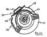
本発明に係る表示システムの実施形態は、図1に示すような、外蓋体10および保持器20を含む基部ユニットならびに詰替え容器カセット30の形態で、薬剤分配器の内部に例示されている。この実施例では、薬剤分配器は、経口吸入するようになっている乾燥粉末吸入器である。電子表示器22を具備する保持器20は、蓋体10の内側に嵌入するように成形され、軸受(図示せず)を介して本体に固定されて軸受回りにその保持器が同軸回転する。止め(図示せず)が保持器20から突出し、保持器20が蓋体10に対して約180度よりも多く回転するのを防止する。この止めは、蓋体10内部で保持器20の2つの位置を画定する。保持器の外部分は、本装置の使用者の親指受けまたは親指以外の指受けとなる凹面後退部26の形態で成形可能である。保持器20は、詰替え容器カセット30が掛止する穴を形成する。 An embodiment of a display system according to the present invention is illustrated inside a drug dispenser in the form of a base unit including an
詰替え容器カセット30は、薬剤保持体を収納する容器と、薬剤を取り出すために保持体を開封する機構とを備える。詰替え容器カセット30は後方部分32を有し、それは、カセット30の他の部分が保持器20の内部に収納されているときに、保持器20から取り出すためにカセットを手で把持できるように、保持器20の切欠き部分によって露出されている。 The
詰替え容器カセット30はマウスピース36も有し、そこから使用者がカセット30から分配された薬剤を吸入する。 The
図2aは、カセット30が保持器20中の定位置に納まり、カセットの後端部32が露出された非分配位置に蓋体10がある薬剤分配器を示す。カセット30は、バネ偏倚式の留め(図示せず)によって定位置に固定される。カセット30が保持器20に対して図示の位置にあるとき、蓋体10はマウスピース(図示せず)を覆う。蓋体10は、割送りレバー(図示せず)の親指タブ28も保護し、これは薬剤分配器が使用されていないときに薬剤保持体の偶発的な割送りを防止する。 FIG. 2a shows a drug dispenser with the
図2bは、図1および2aの薬剤分配器を示すが、カセット30は保持器20中の定位置で分配位置にある。保持器20は、保持器20上の止めが蓋体10に当接するように蓋体10に対して回転されている。保持器20はマウスピース36を露出させるために別の切欠き部分を有することが理解できる。 FIG. 2 b shows the drug dispenser of FIGS. 1 and 2 a, but the
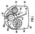
図3は、薬剤保持体を収納する詰替え容器カセット30の内部機構を模式的に示すが、ポケットの多くには乾燥粉末の形態にある薬剤の個別用量が充填された状態にある。この内部機構は、割送り車60と、蓋シート58の使用済み部分を巻き取る蓋巻取り車70とを備える。割送り車60は、車軸と平行に延びる複数の凹部62a、62bを有する。これらの凹部62a、62bは、隣接するポケット54a、54bの中心線間の間隔に等しいピッチで離間されている。 FIG. 3 schematically shows the internal mechanism of the
カセット30は、薬剤保持体の内部に含まれた用量を使用する前に、それが輪状に巻かれている領域80と、薬剤保持体の使用済み基部が回収される領域82とを含む。領域82は、基部シートの使用済み部分が巻き取られる基部巻取り車86を内蔵し、割送り車60と蓋巻取り車70とを基部巻取り車86に同期して一方向に回転させるようにスピンドル機構(図示せず)が配置されている。 The
動作に際して、使用者は、保持器を本体に対して移動してカセットを分配位置に移動し、次いで、レバーの指タブを押してそれを移動させる。これは割送り車60の回転に繋がり、それによって基部巻取り車86および蓋巻取り車70の両方が回転することになり、よって、未だ開封されていないポケットの中身を粉末出口の端部に対向して露出するのに十分な間隔にわたって、基部シートと蓋シートとを剥離する。次いで、患者はマウスピースを介して粉末状の薬剤を吸入することができる。 In operation, the user moves the retainer relative to the body to move the cassette to the dispensing position and then pushes the finger tab on the lever to move it. This leads to the rotation of the indexing wheel 60, which causes both the
図2bは、割送りレバーの親指タブ28がリセット位置にあり、駆動するばかりになっているのを示す。親指タブ28を駆動すると、詰替え容器カセット30の内部の薬剤保持体を割送り、それによってマウスピース36を介して吸入されるばかりになった薬剤の用量を露出する。図2bに示した表示器22は、下でさらに詳細に説明することになるが、経過時間を表す1組の複数の示標および1組の複数の用量回数示標のグラフィック表示を含む。 FIG. 2b shows that the index
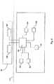
図4は、薬剤分配器の電子サブシステムを示す模式的なブロック線図である。保持器20は、例えば、内部刻時機構を含むマイクロプロセッサチップの形態にある内蔵制御ユニット90を具備する。同じく保持器20の中に収納され、薬剤分配器に電力を供給する電池の電圧を閾値に対して監視する電池電圧センサ92を含めて、様々なセンサが制御ユニット90に電気的に接続されている。いくつかの実施形態では、制御ユニット90が蓋体開放センサ94を具備することが可能であり、それは、蓋体が分配器のマウスピースを覆う非分配位置から、薬剤の分配が可能な開放位置まで、保持器に対して移動するのを感知する。 FIG. 4 is a schematic block diagram showing the electronic subsystem of the drug distributor. The
本発明の実施形態は表示システムの態様に関し、特に、服薬遵守性データを提供するために薬剤システムによって有用に利用され得る態様に関する。服薬遵守性に関連して、実施形態は、好ましい投薬計画に対する使用者の服薬遵守性の高さまたは低さ、すなわち、使用者の実際の薬剤分配時間と薬剤を分配すべき時間との間の相互関係に対する使用者の理解を深めることに関する。 Embodiments of the present invention relate to aspects of a display system, and more particularly to aspects that can be usefully utilized by a drug system to provide compliance data. In relation to medication compliance, embodiments may provide a high or low user compliance for a preferred dosing schedule, i.e., between the user's actual drug delivery time and the time at which the drug should be dispensed. It relates to deepening the user's understanding of interrelationships.
本発明の実施形態では、装置の使用に関連する所与の事象の検出に応答して表示モードが選択され、この選択は、この所与の事象が発生した時間に応じる。一実施形態では、表示モードの選択が、先行事象の発生とこの所与の事象の発生との間の時間に応じ、他方で別の実施形態では、この選択が、所与の事象の実際の発生時間に応じる。よって、一実施形態は相対時間に基づくもの、すなわち、使用者が先行事象に対して所与の事象の発生段階を確認できるようにする情報を使用者に提供するものであり、他方で他の実施形態は絶対時間に基づくものである。 In an embodiment of the present invention, a display mode is selected in response to detection of a given event associated with the use of the device, the selection being dependent on the time at which the given event occurs. In one embodiment, the selection of the display mode depends on the time between the occurrence of the preceding event and the occurrence of the given event, while in another embodiment, this selection is the actual event of the given event. Depending on the time of occurrence. Thus, one embodiment is based on relative time, i.e., provides the user with information that allows the user to confirm the stage of occurrence of a given event relative to the preceding event, while other Embodiments are based on absolute time.
薬剤分配器の関連では、事象には薬剤の用量を服用することが含まれ、したがって、その表示モードは、使用者が先行服用用量の時間に対して、所与の事象に対応する段階を確認できるようにする情報を使用者に提供する。一実施形態では、これらの段階には「尚早」、「予定時刻」、または「遅刻」が含まれ、それは、使用者に事象(すなわち、使用者が用量を服用した時間)が、先行服用用量(先行事象)に対して「尚早」であったか、「予定時刻」であったか、または「遅刻」であったかを知らせる。 In the context of a drug dispenser, an event involves taking a dose of the drug, so its display mode confirms the stage at which the user responds to a given event relative to the time of the previous dose. Provide users with information that enables them to do so. In one embodiment, these stages include “premature”, “scheduled time”, or “late”, which indicates to the user that the event (ie, the time when the user took the dose) It is informed whether (previous event) was “early early”, “scheduled time”, or “late”.
ここで、薬剤分配器と組み合わせた本発明の様々な実施形態をさらに詳細に説明する。 Various embodiments of the present invention in combination with a drug dispenser will now be described in further detail.
再び図4を参照すると、制御ユニット90は用量が服用されたことを検出する手段を具備し、第1の構成では、この手段は詰替え容器カセット30の一部である用量センサ107を含む。用量センサ107は、制御ユニット90の中の受信機およびセンサ107の中の送信機を使用するデータ通信インターフェース110を介して制御ユニット90とデータ通信する。割送り車60が回転すると、用量センサ107は前記回転を感知し、信号を制御ユニット90に送信して用量が服用されるばかりになっていることを示す(その前提は、用量が引き続いて服用されることである)。 Referring again to FIG. 4, the
薬剤分配器の様々な状態が、先行用量が分配されてからの経過時間の段階を含めて、図4に例示した電子的サブシステムによって検出可能である。用量が分配および/または吸入された後で、制御ユニット90は、先行用量が服用されたことが検出されてから経過した時間を監視する経過時間機能を開始する。一旦、次の用量が服用されたことが検出されると経過時間機能が停止し、制御ユニット90は、先行服用用量と直近の服用用量との間の経過時間量を使用して表示モードを選択する。制御ユニット90は表示器22に作用的に結合し、適切な表示モードの選択が表示器22の上に1つまたは複数の識別子を表示させる。したがって、この実施形態では、表示システムは制御ユニット90によって提供される。 Various states of the drug dispenser can be detected by the electronic subsystem illustrated in FIG. 4, including the time elapsed since the previous dose was dispensed. After the dose has been dispensed and / or inhaled, the
図5a、5b、5c、6、7、9a、9b、10、および11のそれぞれは、表示器22の画面構成の別法による実施形態を示し、それによって表示モードを使用者に示すことができる。少なくとも1つの実施形態では、表示モードのそれぞれが、示標を分割LCD表示器上に表示させる。以下では、画面構成のそれぞれの要素の説明が、同じ参照符号(100の倍数づつ増分した)を使用する異なる画面構成のそれぞれの中で表示された同じ示標に該当することを理解すべきことに留意されたい。示標の厳密な形態は異なるが、それらの機能および制御ユニット90によるその制御は同様であり、したがって1つの構成中の示標に関する説明は、異なる構成中の同様の参照符号を附した示標にも等しく該当することを理解すべきである。 Each of FIGS. 5a, 5b, 5c, 6, 7, 9a, 9b, 10 and 11 shows an alternative embodiment of the screen configuration of the
ここで、図5aを参照して第1の実施形態を説明する。この実施形態および以下の実施形態では、先行事象(それからの経過時間が測定される)を第1の事象と呼び、この先行事象に続く事象(その発生が経過時間の段階を画定する)を第2の事象と呼ぶ。したがって最初に図5aを参照すると、第1の実施形態では、表示器22は3つの領域501a、501b、501cを含み、それらは、例えば、それぞれが第1の事象が発生した時間と第2の事象が発生した時間との間の経過時間の異なる段階を別個に示す。領域501a、501b、501cは静的示標によって設けられることが好ましい。 A first embodiment will now be described with reference to FIG. In this embodiment and the following embodiments, the preceding event (after which the elapsed time is measured) is referred to as the first event, and the event following this preceding event (the occurrence of which defines the stage of elapsed time) is the first event. Called
第1の領域501aは「尚早」段階に対応し、第1の事象の発生と第2の事象の発生との間の経過時間の段階が、当該薬剤に関する投薬計画に対して尚早であることを示す。第2の領域501bは「予定時刻」段階に対応し、したがって第1の事象の発生と第2の事象の発生との間の経過時間の段階が当該薬剤に関する投薬計画に従っていることを示す。さらに第3の領域501cは「遅刻」段階に対応し、第1の事象の発生と第2の事象の発生との間の経過時間の段階が当該薬剤に関する投薬計画に対して遅刻していることを示す。明白なことであるが、領域501a、501b、501cは、このような様態通りに厳密に画定される必要はなく、他の実施形態では、表示が3つの領域よりも多く含む。しかし、領域のそれぞれが薬剤に関する投薬計画に対して特定の意味を有することが好ましい。本図および以降の図では、これらの領域501a、501b、501cには、特定の領域の識別を助けるために異なる模様(それぞれに点、縞、煉瓦模様)が割り当てられる。それぞれの領域501a、501b、501cが、異なる色(または表示器22が白黒であれば、灰色の異なる濃淡度)を有し、使用者にはどの色(または濃淡度)が異なる段階に関連するかが知らされていることが好ましい。別法としてまたは追加的に、それぞれの領域501a、501b、501cが、その中に文字列、例えば、それぞれ「尚早」、「定刻通り!」、および「遅刻」を有し得る。 The
本実施例では、表示モードが、可能な3つの表示モード(1つのみ、すなわち、第3の表示モードが示されている)、すなわち、「尚早」領域501a中に示標503を有する第1の表示モード、「予定時刻」領域501b中に示標503を有する第2の表示モード、および「遅刻」領域501c中に示標503を有する第3の表示モード(図5c)から選択される。この実施形態では、表示モードが、活動化可能な示標503によって、どの領域が当該経過時間の段階に対応するのかを他の領域から区別するようになっている。別法として、第1の事象と第2の事象との間の経過時間の段階に対応する領域(ここでは領域501c)が点滅可能であるか、またはこの領域の境界が強調可能であり、それによって対応する領域501cが、その他の領域501a、501bに較べて、一段と目立つようにする。 In this embodiment, the display mode is one of three possible display modes (only one, ie, the third display mode is shown), that is, a first having an
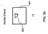
図5bおよび5cに注目すると、別法として、表示器が1つの活動化可能な領域501を有することが可能であり、そこでは段階を示す示標503が表示されている。1つの構成(図5b)では、選択表示モードが、第1の事象の発生と第2の事象の発生との間の経過時間の時間数を示し、他方で別の構成(図5c)では、選択表示モードが経過時間の段階を示し、それは図5aで示した複数の領域の1つを識別することと本質的に均等である。段階数(1...3)を示す別法として、示標503が適切な記号を含むように、それぞれの段階を記号と関連付けることも可能であり、したがって図5bに示した構成では、24の表示モードが存在可能であり、図5cに示した構成では、2つ以上の表示モードが存在し得る。 Turning to FIGS. 5b and 5c, alternatively, the display can have one
したがって、この実施形態では、用量が服用された実際の時間が患者には提示されず、その代わりに、患者には用量と用量との間の時間を示す情報が提示される。少なくとも患者は用量と用量との間の時間間隔を知ることが想定され得るので、この実施形態は、有利なことに、患者が薬剤投与計画に対して自分の進捗状況を点検することを可能にする。 Thus, in this embodiment, the actual time when the dose was taken is not presented to the patient, but instead the patient is presented with information indicating the time between doses. This embodiment advantageously allows the patient to check his progress against the drug regimen since at least the patient can be assumed to know the time interval between doses. To do.
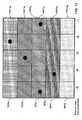
図6は、本発明の第2の実施形態を示すが、それは図5aに示した構成に対応するものであり、表示器22が複数の領域を含む。この実施形態では、表示器22が、複数の先行事象、特に、6つの先行事象に関するデータを示すように構成されている。それぞれの連続する対となる事象に関して、その対中のこれらの2つの事象間の経過時間に応じて表示モードが選択される。本実施例では、5対の事象、すなわち、第1の表示モードに対応する第1事象と第2事象との間の第1の対、第2の表示モードに対応する第2の事象と第3の事象との間の第2の対、第3の表示モードに対応する第3の事象と第4の事象との間の第3の対、第4の表示モードに対応する第4の事象と第5の事象との間の第4の対、第5の表示モードに対応する第5の事象と第6の事象との間の第5の対が存在する。図中には(明瞭にするために)、第1の事象と第2の事象との間の時間に対応する領域601a1、601b1、601c1および第5の事象と第6の事象との間の時間に対応する領域601a5、601b5、601c5のみに参照符号を附す。FIG. 6 shows a second embodiment of the present invention, which corresponds to the configuration shown in FIG. 5a, and the
それぞれの表示モードは、上で説明した3つの表示モードから選択される(示標603iが領域601ai、601bi、601ciの1つの中に位置するように)。したがって、図6は5つの選択表示モードを示し、それぞれが、対中の2つの事象間の経過時間に応じて選択されており、この対を構成する2つの事象間の経過時間の段階を示す示標6031、6032、6033、6034、6035を含む。Each display mode, (as
したがって、表示器22は個々の用量および連続した用量の両方に対する投薬計画の服薬遵守性をグラフィック表示する。したがって、それは用量が服用された時間のばらつきの推移を見る手段となり、患者が薬剤を服用した規則正しさ(または遅刻度)を直ちに理解することを可能にする。 Accordingly, the
表示器22は空間的な制約条件によって限定されるのが一般であり、それは先行事象対の限定的な数(分配履歴)のみが表示可能であるに過ぎないことを意味する。図7を参照すると、表示器22が、第1端711、第2端713、事象対(すなわち、選択表示モード)の数に対応する特定の長さ715を有し、ラップアラウンド(wrap-around)機能を含むようになっている。データが事象対の特定数に関して受信されたものと想定すると、引き続いて検出された事象に対して選択された表示モードが第1端711上に表示され、それによって第2端713に表示されたデータを置き換える。この構成では、現時点の画面上で最も古い表示モードが画面の第2端から削除される。 The
以上の実施形態では、領域は異なる長さを有する時間間隔に対応し、これらの間隔の長さは投薬計画に対応している。例えば、1日1回の投薬計画の場合では、「尚早」段階(領域501a、601aiに対応する)が0と20時間との間にまたがり得る一方で、「予定時刻」段階(領域501b、501biに対応する)が20〜28時間に対応し、かつ「遅刻」段階(領域501c、601ciに対応する)が28時間を超過する任意の時間数に対応し得る。1日2回の投薬計画の場合では、「尚早」段階が0と9時間との間にまたがり得る一方で、「予定時刻」段階が9〜15時間に対応し、かつ「遅刻」段階が15時間を超過する任意の時間数に対応し得る。1日3回の投薬計画の場合では、「尚早」段階が0と6時間との間にまたがり得る一方で、「予定時刻」段階が6〜10時間に対応し、かつ「遅刻」段階が10時間を超過する任意の時間数に対応し得るというようになっている。明白なことであるが、表示器22を制御する制御ユニット90は、当該薬剤が対応する投薬計画を識別するデータを受信し、それを使用して領域501a、501b、501cの範囲を設定できねばならないか、または薬剤分配器が、その中に領域501a、501b、501cの範囲が配線接続されるように特定の投薬計画に適合されることになる。In the above embodiments, the regions correspond to time intervals having different lengths, and the lengths of these intervals correspond to the dosing schedule. For example, in the case of a once-daily dosing schedule, the “premature” phase (corresponding to
制御ユニット90が詰替え容器カセット30から投薬計画情報を読み出すように構成されているものと想定すると、このような投薬計画情報はメモリチップ108(図4に図示)上に設けることが可能であり、それはデータ通信インターフェース110を介して制御ユニット90とデータ通信する。次いで、制御ユニット90は、制御ユニット90中に存在するか、またはメモリチップ108から読み出し得る時限投薬計画を使用して、領域に対応する時間間隔を算定することができる。ここで図8参照し、図5aに示した構成の実施例に関して、この過程をさらに詳細に説明する。ステップ801で、制御ユニット90は詰替え容器カセット30上に格納された投薬計画情報を読み出し、次にステップ803で、領域501a、501b、501cの範囲を識別する。投薬計画情報が、薬剤を1日2回服用すべきことを示すものと想定すると、ステップ803は、制御ユニット90が1日2回の薬剤に対する境界を計算するようになっているアルゴリズムの処理を含む。境界情報が詰替え容器カセット上に格納されていれば、ステップ803は、単に詰替え容器からの境界情報の読出しを含むだけである。次いで制御ユニット90は、用量が服用されたことを示す用量センサ107からの信号を待つ(ステップ804)。 Assuming that the
一旦、このような信号が受信されたら、これが基部ユニットの初回の使用であれば、制御ユニット90は、ステップ805で、その内部刻時機構をリセットして次の信号を待つ(ステップ804)。しかし、これが2回目以降の信号であれば、制御ユニット90は、内部刻時機構に関連する現在のタイマ値を読み出し(ステップ806)、内部刻時機構をステップ807でリセットし、かつこのタイマ値を使用して、ステップ806で読み出されたタイマ値を使用する3つの可能な表示モードから表示モードを選択する(ステップ809)。ステップ803で識別された情報が、「尚早」段階が0〜8時間に対応し、「予定時刻」段階が8〜15時間に対応し、そして「遅刻」段階が15時間を超過する任意の時間に対応することを示せば、ステップ806で読み出されたタイマデータが10時間であると想定すると、制御ユニット90は、示標503が「予定時刻」領域501bの中に存在する表示モードを選択する(ステップ809)。次いで、制御ユニット90はステップ809で選択された表示モードを呼び出し(ステップ811)、次の信号の確認(ステップ804)に戻る。 Once such a signal is received, if this is the first use of the base unit, the
制御ユニット90の内部刻時機構は、詰替え容器30の存在とは無関係にまたは別様に、経過時間を追跡するように構成可能であることに留意すべきである。これは、事象間の経過時間の監視が、詰替え容器30の交換によって影響を受けることがなく、したがって制御ユニット90は1個の詰替え容器カセットの最後の用量と次の詰替え容器カセットの最初の用量との間の時間間隔を引き続き記録できることを意味する。 It should be noted that the internal clocking mechanism of the
上で説明したように、表示器22は第1の側711および第2の側713を有し、直近の事象に関する表示モードは、第1の側711に最も近接する表示領域中に呼び出される。ステップ809で選択された表示モードが第1の表示モードであれば、ステップ811は、この第1の側711に最も近接する表示領域中の選択表示モードに関する示標の表示を含む。しかし、ステップ809で選択された表示モードが2番目以降の呼出し表示モードであれば、ステップ811は、表示器22の第2の端713に向かって表示器22上に現時点で表示されている示標をずらすことを追加的に含む。上で説明したように、表示器22は限られたサイズであり、先行用量の特定の数に関するデータを示すことができるに過ぎない。表示器22が6つの先行事象に対応する領域を含むものと想定すると、すなわち、最多で5つの表示モードが同時に呼出し可能であれば、制御ユニット90は、ステップ809で選択された表示モードを呼び出す前に、現在処理中の信号が第6番目以降の事象に関連するかどうかを確認する(ステップ821)。これがその場合に該当すれば、ステップ823で、制御ユニット90は、表示器22の第2の端713に最も近接して位置する領域中に表示された示標を、その他の領域中に位置する指標を第2の端713に向かってずらすことによって置き換える(ステップ811の一部として)。 As described above, the
複数の領域を含み、その1つが、第1の事象の発生と第2の事象の発生との間の経過時間の段階を示すために、少なくとも1つの他の領域から区別可能である表示器の別法として、図5bおよび5cを参照して説明したように、表示器は、その中に示標を有する単一の領域を含み得る。この別法による構成では、選択された表示モードは、その領域中に1つまたは複数の示標が呼び出されることになる。このような示標は、第1の事象の発生と第2の事象の発生との間の経過時間数または経過時間の段階を示す。図9aおよび9bは、複数の先行事象、特に、6つの先行事象(したがって5つの先行用量間隔および5つの表示モードの選択)に関するデータを示し、よって図6と均等である。先行用量以来の時間数を表示する利点は、段階の数が表示されるとき(または、それに関してさらに言えば、表示器が2つ以上の領域を含み、それぞれが1つの段階に対応するとき)よりも一連の用量にわたって服用時間のばらつきが明白なことであるが、それは、それぞれの段階が数時間に対応し、かつその段階の範囲内のどの時点で用量が服用されたかを知ることができないからである。 An indicator that includes a plurality of regions, one of which is distinguishable from at least one other region to indicate the stage of elapsed time between the occurrence of the first event and the occurrence of the second event. Alternatively, as described with reference to FIGS. 5b and 5c, the indicator may include a single region having an indicator therein. In this alternative configuration, the selected display mode will cause one or more indicators to be invoked in that area. Such an indicator indicates the number of elapsed times or the stage of elapsed time between the occurrence of the first event and the occurrence of the second event. FIGS. 9a and 9b show data for multiple preceding events, in particular 6 preceding events (thus the selection of 5 preceding dose intervals and 5 display modes) and is therefore equivalent to FIG. The advantage of displaying the number of hours since the previous dose is when the number of stages is displayed (or more specifically, when the indicator includes more than one region, each corresponding to one stage) It is more obvious that the variation in dose time over a series of doses, but it is not possible to know when each step corresponds to several hours and at which point within the range of the dose the dose was taken Because.
上で説明した第1および第3の構成(図5aおよび5bならびに図6および9bに関して)では、投薬計画情報を使用して表示器上の領域の範囲(すなわち、経過時間の段階「尚早」、「予定時刻」、「遅刻」(それぞれ1、2、3))を算定する。しかし、別法による構成では、領域が投薬計画とは無関係であるように、かつ図8で説明したステップ801および803が不要であるかのように設定されている。図10を参照すると、1つの構成では、それぞれの表示器が5つの領域1001a、1001b、1001c、1001d、1001eを含み、その範囲が次のように配分される。すなわち、第1の領域1001aは、0と5時間との間の経過時間に対応する(したがって、投薬計画のすべてに関する経過時間の「尚早」段階に関連する)。第2の領域1001bは、5と10時間との間の経過時間に対応する(それは1日1回および2回の投薬計画に関する経過時間の「尚早」段階と、1日3回および4回の投薬計画に関する経過時間の「予定時刻用量」段階とに対応する(1日3回の投薬計画では、用量が8時間で予定時刻になり、1日4回の投薬計画では、用量が6時間で予定時刻になるからである)。第3の領域1001cは、10と19時間との間の経過時間に対応する(それは、1日2回の投薬計画に関する経過時間の「予定時刻用量」段階と、1日1回の投薬計画に関する経過時間の「尚早」段階と、1日3回および1日4回の投薬計画に関する経過時間の「遅刻」段階とに関連する)。第4の領域1001dは、19と25時間との間の経過時間に対応する(これは、1日1回の投薬計画に関する経過時間の「予定時刻用量」段階と、1日2回、3回および1日4回の投薬計画に関する経過時間の「遅刻」段階とに関連する)。第5の領域1001eは、25時間を超過する経過時間に対応する(これは、投薬計画のすべてに関する経過時間の「遅刻」段階に関連する)。したがって、患者が1日4回の投薬計画に従っていれば、その内科医は、表示モードが第2の領域1001b中に示標1003を含むように示すことが可能であり、他方で患者が1日1回の投薬計画に従っていれば、内科医は、第4の領域1001d中に示標1003を含むように示すことが可能である。 In the first and third configurations described above (with respect to FIGS. 5a and 5b and FIGS. 6 and 9b), the dosing schedule information is used to cover a range of areas on the display (ie, the time stage “early”, Calculate “scheduled time” and “late” (1, 2, 3 respectively). However, in an alternative configuration, the region is set so that it is independent of the dosing schedule and as if
この実施形態は、同じ分配器が4つの異なる投薬計画用に使用可能であり、しかも領域501a、501b、501cの範囲を設定する必要があるソフトウェアおよび/またはハードウェアを含む必要がないので、製造する観点から見て利点がある。この実施形態の特に有効な態様は、それが一連の用量にわたって服用時間のばらつきの推移をより明白に見られる手段を提供する。領域の数が増加すると、ばらつきの程度に関する情報量が増加する。患者は、自分が先行用量に関してどれほど尚早であったか、またはどれほど遅刻であったかを知りたければ、より少ない領域ではなくて、より多くの領域を有することが推奨され得る。しかし、領域の数は表示器22のサイズによって限定されており、したがってより大きな表示器では、それぞれの表示器がこのような領域を5つ以上含むことが可能であるが、他方でより小さい表示器では、それぞれの表示器が、3つの領域を有し得る。表示器のサイズが極端に限定される場合には、単一の領域構成(図5bおよび5cに対応する)が推奨され得る。したがって、段階数を示す示標が表示されるとき(図5cに対応する)、示標は数1と数5との間で変化するか、または別法として数1〜5を示す何らかの記号の間で変化し得る。 This embodiment is manufactured because the same dispenser can be used for four different dosing schedules and does not need to include software and / or hardware that need to set the
上で説明した実施形態では、表示モードの選択が相対時間に基づき、したがって表示器22上の領域は用量間の経過時間の間隔に対応する。しかし、別法による実施形態では、表示器22上の領域は、絶対時間に対応し得る。絶対時間は、時間が24時間後にリセットされる点で、それ自体が相対的である。したがって、1日1回の投薬計画の薬剤に基づく服用量の間隔は24時間時計の間隔と同一である。すなわち、1日1回の投薬計画では、絶対時間に従って選択された表示モードは、2つの連続用量間の経過時間に従って表示モードを選択することと均等である。これは、用量が服用された時間の確認に加えて、用量履歴が、表示モードにおける傾向(前述の実施形態に関して)を詳しく調べることによって追跡可能であることを意味する。図11を参照すると、第1の領域1101aは00:00〜08:00に対応可能であり、第2の領域1101bは08:00〜16:00時に対応可能であり、かつ第3の領域1101cは16:00〜24:00時に対応可能である。上で説明した実施形態に関して、表示モードの呼出しが、事象の検出時間に対応する領域のいずれかの中に示標1103を挿入することを含み、その示標1103は標識、記号、または該当領域を他の領域から区別するようにされた任意の視覚的な識別子である。 In the embodiment described above, the selection of the display mode is based on relative time, so the area on the
前述の実施形態では、事象の対を形成する事象が連続的な事象であるものとして説明されているが、それらは順次の事象であってもまたは非順次の事象であってもよい。 In the foregoing embodiment, the events forming the event pair are described as being continuous events, but they may be sequential events or non-sequential events.
前述の実施形態では、薬剤の分配に関する事象が割送り車60の動きによって検出されるものとして説明されている。しかし、検出システムは、分配器の使用を示す他の事象を検出するように構成することが可能である。これらの事象には、蓋体10の開放、マウスピース36中の流量変化および圧力変化が含まれ、したがって検出システムには蓋体移動検出器ならびに/または静的および動的圧力を測定するように(例えば、圧電性結晶によって)構成された圧力測定装置が含まれ得る。再び図4を参照すると、検出システムは、放射をマウスピースの中に放出する放射放出体104およびマウスピースの他方の側で放出放射を検出する吸入センサ106を追加的にまたは別法として含み得る。使用者が吸入するときに、薬剤粉末が放射放出体104によって放出された放射を散乱させ、それによって吸入センサ106における放射検出の水準が低下して用量が吸入されたことを示す。薬剤分配器が、このように薬剤を分配すべき時間まで保持器の中に配置されている場合では、分配器の脱着も分配器の使用を示す事象となり得るが、その場合では、検出システムは、保持器の中に配置され、分配器の存在または保持器からの分配器の脱着を示す信号を協働して供給する発光体と検出器との対を含み得る。 In the above-described embodiment, the event relating to the dispensing of the medicine is described as being detected by the movement of the index wheel 60. However, the detection system can be configured to detect other events that indicate use of the distributor. These events include the opening of the
以上の説明では、その実施形態が薬剤分配器の一部を構成するものとして説明されたが、本表示システムは、定期的な装置の使用を伴う任意の事象に本質的に対応するので、本表示システム(制御ユニット90で実施された)を使用して非薬剤状況でも使用可能である。例えば、本表示システムは電気歯ブラシと併用可能であり、その場合では装置の使用を示す動作には、例えば、歯ブラシをその保持器から取り出すことが含まれる。 In the above description, the embodiment has been described as forming part of a drug dispenser, but the present display system essentially addresses any event that involves the use of a regular device. It can also be used in non-drug situations using the display system (implemented in the control unit 90). For example, the present display system can be used with an electric toothbrush, in which case the operation indicating the use of the device includes, for example, removing the toothbrush from its retainer.
以上では、表示器22が分割LCD表示器の形態を取る。分割LCD表示器では、表示示標が、表示画面中に予め構成され、かつ制御ユニット90の制御下で個別に活動化可能な個々の液晶要素によって構成される。分割表示器を使用する利点は、コストの低さと共に明瞭度の高さである。表示器は白黒であっても、またはカラーであってもよい。この場合も、高い明瞭度および低いコストに関しては、白黒の表示器が好ましい。表示器は他の形態を取り得るが、例えば、LEDの構成または画素化LCD表示器のような画面を含んでもよい。 In the above, the
メモリチップ108が電気接点を介して制御ユニット90と通信するものとして説明されているが、メモリチップ108は、高周波(RFID)タグの形態でもよく、データ通信インターフェース110は無線通信インターフェースでもよい。 Although the
本発明に係る薬剤分配器は、特に喘息および慢性閉塞性肺疾患(COPD)のような呼吸器疾患の治療用の薬剤の分配に適切である。 The drug dispenser according to the present invention is particularly suitable for dispensing drugs for the treatment of respiratory diseases such as asthma and chronic obstructive pulmonary disease (COPD).
したがって、例えば適切な薬剤は、鎮痛薬、例えば、コデイン、ジヒドロモルヒネ、エルゴタミン、フェンタニル、またはモルヒネ;狭心症製剤、例えば、ジルチアゼム;抗アレルギー薬、例えば、クロモグリケート(例えば、ナトリウム塩として)、ケトチフェン、またはネドクロミル(例えば、ナトリウム塩として);抗感染薬、例えば、セファロスポリン、ペニシリン、ストレプトマイシン、スルフォンアミド、テトラサイクリン、およびペンタミジン;抗ヒスタミン薬、例えば、メタピリレン;抗炎症薬、例えば、ベクロメサゾン(例えば、二プロピオン酸エステルとして)、フルチカゾン(例えば、プロピオン酸エステルとして)、フルニソリド、ブデソニド、ロフレポニド(rofleponide)、モメタゾン(例えば、フランカルボン酸エステルとして)、シクレソニド、トリアムシノロン(例えば、アセトニドとして)、または6α,9α−ジフルオロ−11β−ヒドロキシ−16α−メチル−3−オキソ−17α−プロピオニルオキシ−アンドロスタ(androsta)−1,4−ジエン−17β−カルボチオ酸S−(2−オキソ−テトラヒドロ−フラン−3−イル)エステル;鎮咳薬、例えば、ノスカピン;気管支拡張薬、例えば、アルブテロール(例えば、遊離塩基または硫酸塩として)、サルメテロール(例えば、キシナホ酸塩として)、エフェドリン、アドレナリン、フェノテロール(例えば、臭化水素酸塩として)、フォルモテロール(例えば、フマル酸塩として)、イソプレナリン、メタプロテレノール、フェニレフリン、フェニルプロパノラミン、ピルブテロール(例えば、酢酸塩として)、レプロテロール(例えば、塩酸塩として)、リミテロール、テルブタリン(例えば、硫酸塩として)、イソエタリン、ツロブテロール、または4−ヒドロキシ−7−[2−[[2−[[3−(2−フェニルエトキシ)プロピル]スルホニル]エチル]アミノ]エチル−2(3H)−ベンゾチアゾロン;アデノシン2aアゴニスト、例えば、2R,3R,4S,5R)−2−[6−アミノ−2−(1S−ヒドロキシメチル−2−フェニル−エチルアミノ)−プリン−9−イル]−5−(2エチル−2H−テトラゾール−5−イル)−テトラヒドロ−フラン−3,4−ジオール(例えば、マレイン酸塩として);α4インテグリン阻害剤、例えば、(2S)−3−[4−({[4−(アミノカルボニル)−1−ピペリジニル]カルボニル}オキシ)フェニル]−2−[((2S)−4−メチル−2−{[2−(2−メチルフェノキシ)アセチル]アミノ}ペンタノイル)アミノ]プロパン酸(例えば、遊離酸またはカリウム塩として);利尿薬、例えば、アミロライド;抗コリン作用薬、例えば、イプラトロピウム(例えば、臭化物として)、チオトロピウム、アトロピン、またはオキシトロピウム;ホルモン、例えば、コルチゾン、ヒドロコルチゾン、またはプレドニゾロン;キサンチン、例えば、アミノフィリン、コリンテオフィリネート、リジンテオフィリネート、またはテオフィリン;治療用タンパク質およびペプチド、例えば、インシュリンまたはグリカゴン;ワクチン、診断薬、および遺伝子治療薬から選択可能である。適切であれば、薬剤の活性および/または安定性を最適化するために、薬剤は塩の形態で(例えば、アルカリ金属もしくはアミン塩として、または酸付加塩として)またはエステルとして(例えば、低級アルキルエステル)または溶媒和物(例えば、水和物)として使用可能であることは当業の熟練者には明白であろう。Thus, for example, suitable agents are analgesics such as codeine, dihydromorphine, ergotamine, fentanyl, or morphine; angina preparations such as diltiazem; antiallergic agents such as cromoglycate (eg, as a sodium salt) , Ketotifen, or nedocromil (eg, as a sodium salt); anti-infectives such as cephalosporin, penicillin, streptomycin, sulfonamides, tetracyclines, and pentamidine; antihistamines such as metapyrene; anti-inflammatory drugs such as beclomethasone (E.g. as dipropionate), fluticasone (e.g. as propionate), flunisolide, budesonide, rofleponide, mometasone (e.g. Carboxylic acid esters), ciclesonide, triamcinolone (eg, as acetonide), or 6α, 9α-difluoro-11β-hydroxy-16α-methyl-3-oxo-17α-propionyloxy-androsta-1,4- Diene-17β-carbothioic acid S- (2-oxo-tetrahydro-furan-3-yl) ester; antitussives such as noscapine; bronchodilators such as albuterol (eg as free base or sulfate), salmeterol ( For example, as xinafoate), ephedrine, adrenaline, fenoterol (eg, as hydrobromide), formoterol (eg, as fumarate), isoprenaline, metaproterenol, phenylephrine, phenylpropanolamide , Pyrbuterol (e.g. as acetate), reproterol (e.g. as hydrochloride), limiterol, terbutaline (e.g. as sulfate), isoetarine, tubuterol, or 4-hydroxy-7- [2-[[2-[[ 3- (2-phenylethoxy) propyl] sulfonyl] ethyl] amino] ethyl-2 (3H) -benzothiazolone; adenosine 2a agonists such as 2R, 3R, 4S, 5R) -2- [6-amino-2- ( 1S-hydroxymethyl-2-phenyl-ethylamino) -purin-9-yl] -5- (2ethyl-2H-tetrazol-5-yl) -tetrahydro-furan-3,4-diol (eg maleate as); alpha4 integrin inhibitors, for example, (2S) -3- [4 - ({[4- ( Aminokaruboni L) -1-piperidinyl] carbonyl} oxy) phenyl] -2-[((2S) -4-methyl-2-{[2- (2-methylphenoxy) acetyl] amino} pentanoyl) amino] propanoic acid (e.g. Diuretics such as amiloride; anticholinergics such as ipratropium (eg as bromide), tiotropium, atropine, or oxitropium; hormones such as cortisone, hydrocortisone, or prednisolone Xanthines, such as aminophylline, choline theophyllineate, lysine theophyllineate, or theophylline; therapeutic proteins and peptides, such as insulin or glycagon; vaccines, diagnostic agents, and gene therapy agents can be selected. Where appropriate, the drug may be in the form of a salt (eg, as an alkali metal or amine salt, or as an acid addition salt) or as an ester (eg, lower alkyl) to optimize the activity and / or stability of the drug. It will be apparent to those skilled in the art that they can be used as esters) or solvates (eg, hydrates).
好ましい薬剤は、アルブテロール、サルブタモール、サルメテロール、プロピオン酸フルチカゾン、およびプロピオン酸ベクロメタゾン、ならびにその塩または溶媒和物、例えば、アルブテロールの硫酸塩およびサルメテロールのキシナホ酸塩から選択される。 Preferred agents are selected from albuterol, salbutamol, salmeterol, fluticasone propionate, and beclomethasone propionate, and salts or solvates thereof, such as albuterol sulfate and salmeterol xinafoate.
薬剤は組合せで送達することもできる。活性成分の組合せを含む好ましい製剤が、ベクロメタゾンエステル(例えば、二プロピオン酸塩)またはフルチカゾンエステル(例えば、プロピオン酸塩)またはブデソニドのような抗炎症ステロイドと組み合わせたサルブタモール(例えば、遊離塩基または硫酸塩として)またはサルメテロール(例えば、キシナホ酸サルメテロールとして)またはフォルモテロール(例えば、フマル酸塩として)を含有する。特に好ましい組合せは、プロピオン酸フルチカゾンとサルメテロールまたはその塩(特にキシナホ酸塩)との組合せである。特に興味のある他の組合せは、ブデソニドとフォルモテロール(例えば、フマル酸塩として)との組合せである。 The drugs can also be delivered in combination. Preferred formulations containing a combination of active ingredients are salbutamol (eg free base or sulfate) in combination with an anti-inflammatory steroid such as beclomethasone ester (eg dipropionate) or fluticasone ester (eg propionate) or budesonide As) or salmeterol (eg as salmeterol xinafoate) or formoterol (eg as fumarate). A particularly preferred combination is a combination of fluticasone propionate and salmeterol or a salt thereof (particularly xinafoate). Another combination of particular interest is the combination of budesonide and formoterol (eg, as fumarate).
一般に、気管支または肺の肺胞領域に送達するのに適切な粉末薬剤粒子は、10マイクロメートル未満、好ましくは6マイクロメートル未満の空力粒径を有する。鼻腔、口腔、または咽喉のような気道の他の部分への送達が所望であれば、他の粒径の粒子が使用可能である。薬剤は純粋な薬物として送達可能であるが、さらに適切には、薬剤は、吸入に適切な賦形剤(担体)と一緒に送達されることが好ましい。適切な賦形剤には、多糖類(すなわち、デンプン、セルロース、および同様物)、乳糖、グルコース、マンニトール、アミノ酸、およびマルトデキストリンのような有機賦形剤、ならびに炭酸カルシウムまたは塩化ナトリウムのような無機賦形剤が含まれる。乳糖が好ましい賦形剤である。 In general, powder drug particles suitable for delivery to the alveolar region of the bronchus or lung have an aerodynamic particle size of less than 10 micrometers, preferably less than 6 micrometers. Other particle sizes can be used if delivery to other parts of the respiratory tract such as the nasal cavity, oral cavity, or throat is desired. The drug can be delivered as a pure drug, but more suitably, the drug is preferably delivered with an excipient (carrier) suitable for inhalation. Suitable excipients include polysaccharides (ie starch, cellulose, and the like), organic excipients such as lactose, glucose, mannitol, amino acids, and maltodextrins, as well as calcium carbonate or sodium chloride. Inorganic excipients are included. Lactose is a preferred excipient.
粉末薬剤および/または賦形剤の粒子は、従来技術、例えば、微粉化、製粉、またはふるい分けによって作製可能である。さらには、薬剤および/または賦形剤の粉末は、粒子密度、粒径範囲、または特性に関して設計可能である。粒子は、活性剤、表面活性剤、壁形成材料、通常の当業者が望ましいと考える他の成分を含む。 Powdered drug and / or excipient particles can be made by conventional techniques such as micronization, milling, or sieving. Furthermore, drug and / or excipient powders can be designed for particle density, particle size range, or properties. The particles include an active agent, a surfactant, a wall forming material, and other components as would be desired by one of ordinary skill in the art.
賦形剤は、よく知られた方法によって、例えば、添加、共同沈降などによって薬剤に含まれ得る。賦形剤と薬物の調合物は、調合物が用量に中に厳密に計量されかつ拡散され得るように配合されるのが典型である。例えば、標準的な調合物は、50マイクログラムの薬物と混合された13000マイクログラムの乳糖を含有し、260:1の賦形剤対薬物比が得られる。100:1から1:1までの賦形剤対薬物比を有する用量調合物が使用可能である。しかし、非常に低い賦形剤対薬物比では、薬物用量の再現精度の安定性がより低下する恐れがある。 Excipients can be included in the drug by well-known methods, for example, by addition, coprecipitation, and the like. Excipient and drug formulations are typically formulated so that the formulation can be precisely metered and diffused into doses. For example, a standard formulation contains 13000 micrograms of lactose mixed with 50 micrograms of drug, resulting in an excipient to drug ratio of 260: 1. Dose formulations with an excipient to drug ratio from 100: 1 to 1: 1 can be used. However, at very low excipient to drug ratios, the stability of drug dose reproducibility may be further reduced.
本開示は例示目的のみのためにあり、本発明はその変更、変形、および改良にも及ぶものであり、かつ異なる実施形態の如何なる要素も本発明の他の実施形態を構成するために組み合わせ得ることが理解されよう。 This disclosure is for purposes of illustration only, and the invention extends to modifications, variations, and improvements thereof, and any element of a different embodiment may be combined to form other embodiments of the invention. It will be understood.
本明細書および特許請求の範囲が一部を構成する本出願は、後続の出願のいずれに関しても優先権の根拠として使用され得るものである。このような後続の出願の特許請求の範囲は、本明細書に説明の特徴または特徴の組合せにいずれも関連し得る。それらは製品クレーム、方法クレーム、または使用クレームの形態を取ることが可能であり、さらには、例示としてかつ限定されることなく、添付の特許請求の範囲の1つまたは複数のクレームを含み得る。 The application of which this description and claims forms part may be used as a basis for priority in respect of any subsequent application. The claims of such subsequent application may be related to any feature or combination of features described herein. They may take the form of product claims, method claims, or use claims, and may further include one or more of the appended claims, by way of example and not limitation.
Claims (20)
Translated fromJapanese前記装置の使用を示す事象を検出できる検出システムと、
データを表示するように構成された表示器とを備え、
前記表示システムは、選択された表示モードを前記表示器上に呼び出すように構成され、さらに所与の前記事象の検出に応答して、選択された表示モードを呼び出すようになっており、前記表示モードは、先行する前記事象と前記所与の事象との間の経過時間に応じて、前記表示システムによって1組の複数の異なる表示モードから選択可能であり、前記異なる表示モードのそれぞれは経過時間の異なる段階を識別する、表示システム。A display system for use in displaying data relating to the use of a device, the display system comprising:
A detection system capable of detecting an event indicative of use of the device;
An indicator configured to display data;
The display system is configured to invoke a selected display mode on the display, and is further adapted to invoke a selected display mode in response to detection of a given event. A display mode can be selected from a set of different display modes by the display system, depending on the elapsed time between the preceding event and the given event, each of the different display modes being A display system that identifies different stages of elapsed time.
前記装置の使用を示す事象を検出できる検出システムと、
データを表示するように構成された表示器とを備え、
前記表示システムは選択された表示モードを前記表示器上に呼び出すように構成され、前記表示モードは複数の異なる表示モードから選択可能であり、前記表示システムは、前記事象の検出に応答して選択された表示モードを呼び出すようになっており、前記表示モードは、前記事象の検出時間シーケンスに応じて前記表示システムによって選択され、前記表示器は複数の領域を含み、前記選択された表示モードは、前記複数の領域の1つを前記複数の領域の他の少なくとも1つから区別するようになっている、表示システム。A display system for use in displaying data relating to the use of a device, the display system comprising:
A detection system capable of detecting an event indicative of use of the device;
An indicator configured to display data;
The display system is configured to invoke a selected display mode on the display, the display mode is selectable from a plurality of different display modes, and the display system is responsive to detecting the event Invoking a selected display mode, wherein the display mode is selected by the display system in response to a detection time sequence of the event, and the display includes a plurality of areas, the selected display A display system, wherein the mode is adapted to distinguish one of the plurality of regions from at least one other of the plurality of regions.
前記製品を収納するように構成された交換可能な詰替え容器を備え、
前記製品を計量分配するように構成された駆動部を備え、
請求項1から12のいずれか一項に記載の表示システムを備え、前記検出システムおよび前記表示器は、前記選択された表示モードが前記駆動部に関係して呼び出されるように前記駆動部と協働し、
前記複数の領域のそれぞれは前記先行事象が発生した異なる時間に関連し、それぞれの時間は前記製品のための使用計画の一部に対応し、前記交換可能な詰替え用容器は前記使用計画を識別するデータを格納するように構成され、前記表示システムは前記使用計画をそこから取り出すように構成される、分配装置。A dispensing device for dispensing products, said device comprising:
Comprising a replaceable refill container configured to store the product;
Comprising a drive configured to dispense the product;
13. A display system according to any one of claims 1 to 12, wherein the detection system and the indicator cooperate with the drive unit such that the selected display mode is invoked in relation to the drive unit. Work,
Each of the plurality of regions is associated with a different time at which the preceding event occurred, each time corresponding to a portion of a use plan for the product, and the replaceable refill container has the use plan. A dispensing device configured to store identifying data, wherein the display system is configured to retrieve the usage plan therefrom.
Applications Claiming Priority (2)
| Application Number | Priority Date | Filing Date | Title |
|---|---|---|---|
| GB0311461AGB0311461D0 (en) | 2003-05-19 | 2003-05-19 | Display system |
| PCT/EP2004/005489WO2004102375A1 (en) | 2003-05-19 | 2004-05-18 | Display system |
Publications (2)
| Publication Number | Publication Date |
|---|---|
| JP2007502683Atrue JP2007502683A (en) | 2007-02-15 |
| JP4635008B2 JP4635008B2 (en) | 2011-02-16 |
Family
ID=9958342
Family Applications (1)
| Application Number | Title | Priority Date | Filing Date |
|---|---|---|---|
| JP2006529887AExpired - LifetimeJP4635008B2 (en) | 2003-05-19 | 2004-05-18 | Display system |
Country Status (6)
| Country | Link |
|---|---|
| US (1) | US7495546B2 (en) |
| EP (1) | EP1625491B1 (en) |
| JP (1) | JP4635008B2 (en) |
| ES (1) | ES2605737T3 (en) |
| GB (1) | GB0311461D0 (en) |
| WO (1) | WO2004102375A1 (en) |
Cited By (4)
| Publication number | Priority date | Publication date | Assignee | Title |
|---|---|---|---|---|
| JP2019512220A (en)* | 2016-03-24 | 2019-05-16 | ニコベンチャーズ ホールディングス リミテッド | Steam supply device |
| US11123501B2 (en) | 2016-03-24 | 2021-09-21 | Nicoventures Holdings Limited | Electronic vapor provision system |
| US11213638B2 (en) | 2016-03-24 | 2022-01-04 | Nicoventures Trading Limited | Vapor provision system |
| US11241043B2 (en) | 2016-03-24 | 2022-02-08 | Nicoventures Trading Limited | Vapor provision apparatus |
Families Citing this family (57)
| Publication number | Priority date | Publication date | Assignee | Title |
|---|---|---|---|---|
| EP2037999B1 (en)* | 2006-07-07 | 2016-12-28 | Proteus Digital Health, Inc. | Smart parenteral administration system |
| DE102006052007B4 (en)* | 2006-11-03 | 2011-12-22 | Siemens Ag | medicament container |
| USD637710S1 (en)* | 2007-03-06 | 2011-05-10 | Otos Wing Co., Ltd. | Portable air supplier |
| DE102007020100A1 (en)* | 2007-04-26 | 2008-10-30 | Braun Gmbh | Toothbrush and method for wireless unidirectional data transmission |
| JP2010529894A (en) | 2007-06-15 | 2010-09-02 | スパンドーファー,マイケル | Drug delivery and monitoring system for ventilators |
| US9125979B2 (en)* | 2007-10-25 | 2015-09-08 | Proteus Digital Health, Inc. | Fluid transfer port information system |
| US8419638B2 (en)* | 2007-11-19 | 2013-04-16 | Proteus Digital Health, Inc. | Body-associated fluid transport structure evaluation devices |
| USD677377S1 (en) | 2009-11-18 | 2013-03-05 | 3M Innovative Properties Company | Inhaler |
| USD673260S1 (en)* | 2009-11-18 | 2012-12-25 | 3M Innovative Properties Company | Inhalation device |
| BR112012019212A2 (en) | 2010-02-01 | 2017-06-13 | Proteus Digital Health Inc | data collection system |
| EP2531096A4 (en) | 2010-02-01 | 2013-09-11 | Proteus Digital Health Inc | Two-wrist data gathering system |
| US9022988B1 (en) | 2010-05-07 | 2015-05-05 | Kavan J. Shaban | System and method for controlling a self-injector device |
| US8869793B1 (en) | 2010-05-18 | 2014-10-28 | Idtx Systems, Inc. | Compact self-contained automated MDI adapters or units for ventilators |
| CA2835527A1 (en)* | 2011-05-25 | 2012-11-29 | Ilona Eggert | Medicament delivery device and method of controlling the device |
| US9993604B2 (en) | 2012-04-27 | 2018-06-12 | Covidien Lp | Methods and systems for an optimized proportional assist ventilation |
| US9064395B2 (en) | 2012-06-08 | 2015-06-23 | Datalogic ADC, Inc. | Bezel with non-metallic materials for cover or platter for a data reader in a checkout station |
| ES2988402T3 (en) | 2012-06-25 | 2024-11-20 | Gecko Health Innovations Inc | Devices, systems and methods for monitoring therapeutic compliance and patient interaction |
| US10362967B2 (en) | 2012-07-09 | 2019-07-30 | Covidien Lp | Systems and methods for missed breath detection and indication |
| US9027552B2 (en) | 2012-07-31 | 2015-05-12 | Covidien Lp | Ventilator-initiated prompt or setting regarding detection of asynchrony during ventilation |
| RU2663632C2 (en) | 2013-03-21 | 2018-08-07 | Конинклейке Филипс Н.В. | System and method for monitoring usage of respiratory medication delivery device |
| MX358899B (en) | 2013-08-28 | 2018-09-07 | Gecko Health Innovations Inc | DEVICES, SYSTEMS AND METHODS FOR MONITORING ADHERENCE AND DEVICES, SYSTEMS AND METHODS TO MONITOR THE USE OF CONSUMABLES DISPENSERS. |
| US10828434B2 (en)* | 2013-08-30 | 2020-11-10 | Adherium (Nz) Limited | Compliance monitor for a medicament inhaler |
| UA29750S (en)* | 2013-11-22 | 2015-07-10 | Гленмарк Фармас& | INHALER |
| US10173025B2 (en) | 2014-04-21 | 2019-01-08 | Idtx Systems, Inc. | Automated drug delivery systems |
| USD795414S1 (en)* | 2014-06-03 | 2017-08-22 | Glenmark Specialty S.A. | Inhaler |
| CA2958891A1 (en) | 2014-08-28 | 2016-03-03 | Microdose Therapeutx, Inc. | Tidal dry powder inhaler with miniature pressure sensor activation |
| IL316543A (en) | 2014-08-28 | 2024-12-01 | Norton Waterford Ltd | Compliance Monitoring Unit for Inhaler |
| CN106714880B (en) | 2014-08-28 | 2021-12-03 | 诺顿(沃特福特)有限公司 | Compliance monitoring module for breath-actuated inhaler |
| US9950129B2 (en) | 2014-10-27 | 2018-04-24 | Covidien Lp | Ventilation triggering using change-point detection |
| GB201420039D0 (en) | 2014-11-11 | 2014-12-24 | Teva Uk Ltd | System for training a user in administering a medicament |
| US10561814B2 (en) | 2014-11-19 | 2020-02-18 | Idtx Systems, Inc. | Automated drug dispensing systems with automated HME bypass for ventilator circuits |
| US10058661B2 (en) | 2014-12-04 | 2018-08-28 | Norton (Waterford) Limited | Inhalation monitoring system and method |
| USD774178S1 (en)* | 2015-03-10 | 2016-12-13 | Reciprocal Labs Corporation | Usage monitoring attachment for a dry powder inhaler |
| USD769439S1 (en)* | 2015-03-18 | 2016-10-18 | Amneal Pharmaceuticals Company Gmbh | Inhalation device |
| USD767114S1 (en)* | 2015-03-18 | 2016-09-20 | Amneal Pharmaceuticals Company Gmbh | Inhalation device |
| USD777904S1 (en)* | 2015-08-12 | 2017-01-31 | Reciprocal Labs Corporation | Usage monitoring attachment for an inhaler |
| USD861852S1 (en)* | 2015-08-13 | 2019-10-01 | Adherium (Nz) Limited | Compliance monitor for a medicament inhaler |
| WO2017051389A1 (en)* | 2015-09-25 | 2017-03-30 | Adherium (Nz) Limited | Adherence monitor for a medicament inhaler |
| CA173518S (en) | 2016-02-08 | 2017-09-01 | Nicoventures Holdings Ltd | Cartridge for an electronic cigarette |
| GB201605102D0 (en) | 2016-03-24 | 2016-05-11 | Nicoventures Holdings Ltd | Mechanical connector for electronic vapour provision system |
| MX390900B (en) | 2016-03-24 | 2025-03-21 | Trudell Medical Int Inc | RESPIRATORY CARE SYSTEM WITH ELECTRONIC INDICATOR. |
| ES2883624T3 (en) | 2016-05-19 | 2021-12-09 | Trudell Medical Int | Smart Valve Retention Chamber |
| ES2988939T3 (en) | 2016-07-08 | 2024-11-22 | Trudell Medical Int Inc | Intelligent Oscillating Positive Expiratory Pressure Device |
| RU2741664C2 (en) | 2016-07-22 | 2021-01-28 | Никовенчерс Трейдинг Лимитед | Case for device for providing vapour |
| CN114177442A (en) | 2016-11-18 | 2022-03-15 | 诺顿(沃特福特)有限公司 | Drug delivery device with electronics |
| JP7014791B2 (en) | 2016-11-18 | 2022-02-01 | ノートン (ウォーターフォード) リミテッド | Inhaler |
| KR102534558B1 (en) | 2016-12-06 | 2023-05-19 | 노턴 (워터포드) 리미티드 | Suction device with integrated electronics module |
| US10426698B2 (en)* | 2016-12-08 | 2019-10-01 | Breeden Brothers, LLC | Pill container with cap |
| MX2019006702A (en) | 2016-12-09 | 2019-08-01 | Trudell Medical Int | Smart nebulizer. |
| USD838835S1 (en)* | 2017-01-24 | 2019-01-22 | Intech Biopharm Ltd. | Inhaler |
| EP3735287B1 (en) | 2018-01-04 | 2025-03-05 | Trudell Medical International Inc. | Smart oscillating positive expiratory pressure device |
| EP3801714A4 (en) | 2018-06-04 | 2022-03-09 | Trudell Medical International | INTELLIGENT HOLDING CHAMBER WITH VALVE |
| AU2020264799A1 (en) | 2019-04-30 | 2021-11-25 | Norton (Waterford) Limited | Inhaler system |
| US11419995B2 (en) | 2019-04-30 | 2022-08-23 | Norton (Waterford) Limited | Inhaler system |
| CA3140949A1 (en) | 2019-05-17 | 2020-11-26 | Norton (Waterford) Limited | Drug delivery device with electronics |
| US11324954B2 (en) | 2019-06-28 | 2022-05-10 | Covidien Lp | Achieving smooth breathing by modified bilateral phrenic nerve pacing |
| CA3152072A1 (en) | 2019-08-27 | 2021-03-04 | Trudell Medical International | Smart oscillating positive expiratory pressure device |
Citations (4)
| Publication number | Priority date | Publication date | Assignee | Title |
|---|---|---|---|---|
| US5921920A (en)* | 1996-12-12 | 1999-07-13 | The Trustees Of The University Of Pennsylvania | Intensive care information graphical display |
| JP2002504398A (en)* | 1998-02-26 | 2002-02-12 | メモス インターナショナル ビー ヴイ | Apparatus, assembly and system for enhancing and monitoring the certainty of ingestion of a product, especially a medicament, and a method of manufacturing the same |
| WO2002039366A1 (en)* | 2000-11-13 | 2002-05-16 | Siemens Medical Solutions Usa, Inc. | A system and method for processing ventilator information |
| JP2005506163A (en)* | 2001-10-19 | 2005-03-03 | グラクソ グループ リミテッド | Medicine dispenser |
Family Cites Families (56)
| Publication number | Priority date | Publication date | Assignee | Title |
|---|---|---|---|---|
| US4223801A (en)* | 1978-01-26 | 1980-09-23 | Carlson Torsten S | Automatic periodic drug dispensing system |
| US4419016A (en)* | 1982-07-02 | 1983-12-06 | American Cyanamid Company | Device for indicating last medication usage |
| US4588303A (en)* | 1984-06-25 | 1986-05-13 | Mediminder Development Limited Partnership | Medical timer apparatus |
| JP2511016B2 (en) | 1987-02-04 | 1996-06-26 | 株式会社東芝 | Trend graph display device |
| US5642731A (en)* | 1990-01-17 | 1997-07-01 | Informedix, Inc. | Method of and apparatus for monitoring the management of disease |
| JPH055A (en) | 1991-06-24 | 1993-01-08 | Kanzaki Paper Mfg Co Ltd | Production of seeding sheet |
| US5363842A (en)* | 1991-12-20 | 1994-11-15 | Circadian, Inc. | Intelligent inhaler providing feedback to both patient and medical professional |
| JPH05184646A (en) | 1992-01-17 | 1993-07-27 | Osamu Kimura | Method for confirming intake of medicine by using medicine intake clock |
| US5408443A (en)* | 1992-08-19 | 1995-04-18 | Polypharm Corp. | Programmable medication dispensing system |
| US5412372A (en)* | 1992-09-21 | 1995-05-02 | Medical Microsystems, Inc. | Article dispenser for monitoring dispensing times |
| US6012450A (en)* | 1993-01-29 | 2000-01-11 | Aradigm Corporation | Intrapulmonary delivery of hematopoietic drug |
| US5497763A (en)* | 1993-05-21 | 1996-03-12 | Aradigm Corporation | Disposable package for intrapulmonary delivery of aerosolized formulations |
| US5505195A (en)* | 1993-09-16 | 1996-04-09 | Medtrac Technologies Inc. | Dry powder inhalant device with dosage and air flow monitor |
| US6390088B1 (en) | 1993-12-13 | 2002-05-21 | Boehringer Ingelheim Kg | Aerosol inhaler |
| US5392952A (en)* | 1994-01-10 | 1995-02-28 | Bowden; James R. | Pill dispensisng device providing overdosage protection |
| US5583832A (en)* | 1994-10-07 | 1996-12-10 | Accucure, L.L.C. | Medical timer, and methods of constructing and utilizing same |
| JPH08110735A (en) | 1994-10-13 | 1996-04-30 | Fuji Xerox Co Ltd | Display input device and image forming device |
| US5666492A (en)* | 1995-01-17 | 1997-09-09 | Glaxo Wellcome Inc. | Flexible computer based pharmaceutical care cognitive services management system and method |
| US5809997A (en)* | 1995-05-18 | 1998-09-22 | Medtrac Technologies, Inc. | Electronic medication chronolog device |
| US6018289A (en) | 1995-06-15 | 2000-01-25 | Sekura; Ronald D. | Prescription compliance device and method of using device |
| US5691932A (en)* | 1996-09-18 | 1997-11-25 | Reiner; Nobert Leo | Care giver data collection and reminder system |
| US6102855A (en)* | 1996-10-22 | 2000-08-15 | Informedix, Inc. | Variable capacity medication container and labeling system for medical monitoring device |
| EP0857456A1 (en) | 1996-11-15 | 1998-08-12 | HealthTech Services Corporation | Interactive medication delivery system with visual patient monitoring |
| US6032155A (en) | 1997-04-14 | 2000-02-29 | De La Huerga; Carlos | System and apparatus for administering prescribed medication to a patient |
| US6529446B1 (en) | 1996-12-20 | 2003-03-04 | Telaric L.L.C. | Interactive medication container |
| US7978564B2 (en)* | 1997-03-28 | 2011-07-12 | Carlos De La Huerga | Interactive medication container |
| US6304797B1 (en) | 1997-07-31 | 2001-10-16 | Rapid Patient Monitoring, L.L.C. | Automated medication dispenser with remote patient monitoring system |
| US6301196B1 (en)* | 1997-08-19 | 2001-10-09 | Stephen W. Daniel | Multiple alarm timepiece with pill compartments |
| US6358058B1 (en) | 1998-01-30 | 2002-03-19 | 1263152 Ontario Inc. | Aerosol dispensing inhaler training device |
| US6234167B1 (en) | 1998-10-14 | 2001-05-22 | Chrysalis Technologies, Incorporated | Aerosol generator and methods of making and using an aerosol generator |
| JP4712193B2 (en) | 1999-03-06 | 2011-06-29 | グラクソ グループ リミテッド | Drug delivery system |
| US6202642B1 (en) | 1999-04-23 | 2001-03-20 | Medtrac Technologies, Inc. | Electronic monitoring medication apparatus and method |
| GB9911388D0 (en) | 1999-05-18 | 1999-07-14 | Glaxo Group Ltd | Dispenser |
| US6335907B1 (en) | 1999-07-23 | 2002-01-01 | Robert Momich | Package with integrated circuit chip embedded therein and system for using same |
| EP1223855B1 (en) | 1999-10-01 | 2006-08-30 | Glaxo Group Limited | Medicament delivery system |
| AR026914A1 (en) | 1999-12-11 | 2003-03-05 | Glaxo Group Ltd | MEDICINAL DISTRIBUTOR |
| WO2001050434A1 (en) | 2000-01-03 | 2001-07-12 | Anoushirvan Mohammadzadeh | Medication reminder system |
| US6252494B1 (en)* | 2000-01-28 | 2001-06-26 | Michael D. Howell | Timed dispenser for programmed fluid consumption |
| EP1176936A1 (en) | 2000-03-09 | 2002-02-06 | Miklos Illyés | Apparatus for dosage of medicaments |
| JP2001343475A (en) | 2000-05-31 | 2001-12-14 | Kooriyama Design Center:Kk | A color display device for displaying time in color and a time display method using the same. |
| NL1015369C2 (en) | 2000-05-31 | 2001-12-03 | Reguliersdam B V | Device for dispensing medicines and for providing information about them. |
| US6662081B1 (en) | 2000-06-08 | 2003-12-09 | Medport Llc | Medication regimen container and system |
| US6411567B1 (en) | 2000-07-07 | 2002-06-25 | Mark A. Niemiec | Drug delivery management system |
| US6435175B1 (en) | 2000-08-29 | 2002-08-20 | Sensormedics Corporation | Pulmonary drug delivery device |
| AU2001289589A1 (en) | 2000-09-22 | 2002-04-02 | Novo-Nordisk A/S | A medication delivery device |
| WO2002030497A1 (en) | 2000-10-09 | 2002-04-18 | Siemens Aktiengesellschaft | Medicament dispenser |
| GB2368061B (en) | 2000-10-20 | 2005-05-11 | Gw Pharmaceuticals Ltd | Dose dispensing apparatus |
| US20020070227A1 (en)* | 2000-12-13 | 2002-06-13 | Terresa Ferruccio | Personal pill dispensing device |
| IL156245A0 (en) | 2000-12-22 | 2004-01-04 | Dca Design Int Ltd | Drive mechanism for an injection device |
| WO2002058771A1 (en) | 2001-01-25 | 2002-08-01 | Clinical Designs Limited | Dispenser for medicament |
| US20020104848A1 (en)* | 2001-02-05 | 2002-08-08 | Burrows Mark D. | Pharmaceutical container having signaling means and associated method of use |
| GB0108208D0 (en) | 2001-04-02 | 2001-05-23 | Glaxo Group Ltd | Medicament dispenser |
| GB2375758A (en) | 2001-05-25 | 2002-11-27 | Taimo Tapio Stenman | Medicine container with indicator device |
| US20020189615A1 (en) | 2001-06-13 | 2002-12-19 | Henry Adam S. | Inhaler with dose control |
| GB0209531D0 (en)* | 2002-04-26 | 2002-06-05 | Glaxo Group Ltd | Medicament dispenser |
| WO2004078236A2 (en)* | 2003-03-04 | 2004-09-16 | Norton Healthcare Limited | Medicament dispensing device with a display indicative of the state of an internal medicament reservoir |
- 2003
- 2003-05-19GBGB0311461Apatent/GB0311461D0/ennot_activeCeased
- 2004
- 2004-05-18USUS10/556,874patent/US7495546B2/ennot_activeExpired - Lifetime
- 2004-05-18ESES04733572.4Tpatent/ES2605737T3/ennot_activeExpired - Lifetime
- 2004-05-18EPEP04733572.4Apatent/EP1625491B1/ennot_activeExpired - Lifetime
- 2004-05-18WOPCT/EP2004/005489patent/WO2004102375A1/enactiveApplication Filing
- 2004-05-18JPJP2006529887Apatent/JP4635008B2/ennot_activeExpired - Lifetime
Patent Citations (4)
| Publication number | Priority date | Publication date | Assignee | Title |
|---|---|---|---|---|
| US5921920A (en)* | 1996-12-12 | 1999-07-13 | The Trustees Of The University Of Pennsylvania | Intensive care information graphical display |
| JP2002504398A (en)* | 1998-02-26 | 2002-02-12 | メモス インターナショナル ビー ヴイ | Apparatus, assembly and system for enhancing and monitoring the certainty of ingestion of a product, especially a medicament, and a method of manufacturing the same |
| WO2002039366A1 (en)* | 2000-11-13 | 2002-05-16 | Siemens Medical Solutions Usa, Inc. | A system and method for processing ventilator information |
| JP2005506163A (en)* | 2001-10-19 | 2005-03-03 | グラクソ グループ リミテッド | Medicine dispenser |
Cited By (4)
| Publication number | Priority date | Publication date | Assignee | Title |
|---|---|---|---|---|
| JP2019512220A (en)* | 2016-03-24 | 2019-05-16 | ニコベンチャーズ ホールディングス リミテッド | Steam supply device |
| US11123501B2 (en) | 2016-03-24 | 2021-09-21 | Nicoventures Holdings Limited | Electronic vapor provision system |
| US11213638B2 (en) | 2016-03-24 | 2022-01-04 | Nicoventures Trading Limited | Vapor provision system |
| US11241043B2 (en) | 2016-03-24 | 2022-02-08 | Nicoventures Trading Limited | Vapor provision apparatus |
Also Published As
| Publication number | Publication date |
|---|---|
| US7495546B2 (en) | 2009-02-24 |
| EP1625491B1 (en) | 2016-09-21 |
| US20070052544A1 (en) | 2007-03-08 |
| JP4635008B2 (en) | 2011-02-16 |
| GB0311461D0 (en) | 2003-06-25 |
| ES2605737T3 (en) | 2017-03-16 |
| EP1625491A1 (en) | 2006-02-15 |
| WO2004102375A1 (en) | 2004-11-25 |
Similar Documents
| Publication | Publication Date | Title |
|---|---|---|
| JP4635008B2 (en) | Display system | |
| US7233228B2 (en) | Alerting system | |
| JP4314191B2 (en) | Drug dispenser | |
| EP1255580B1 (en) | Housing for an inhaler | |
| US8240301B2 (en) | Dispensing device | |
| US7072738B2 (en) | Medicament dispenser | |
| US20040117062A1 (en) | Medicament dispenser | |
| US20050119604A1 (en) | Medicament dispenser | |
| US20040158349A1 (en) | Medicament dispenser | |
| CN114025815B (en) | Drug delivery device with electronics | |
| CN114206416A (en) | Drug delivery device with electronics and power management | |
| JP2003510736A (en) | Drug delivery system | |
| AU2003281751A1 (en) | Medicament dispenser | |
| KR20230028776A (en) | inhaler system | |
| CN115699203A (en) | Inhaler system |
Legal Events
| Date | Code | Title | Description |
|---|---|---|---|
| A621 | Written request for application examination | Free format text:JAPANESE INTERMEDIATE CODE: A621 Effective date:20070404 | |
| A131 | Notification of reasons for refusal | Free format text:JAPANESE INTERMEDIATE CODE: A131 Effective date:20100105 | |
| A601 | Written request for extension of time | Free format text:JAPANESE INTERMEDIATE CODE: A601 Effective date:20100330 | |
| A602 | Written permission of extension of time | Free format text:JAPANESE INTERMEDIATE CODE: A602 Effective date:20100406 | |
| A521 | Request for written amendment filed | Free format text:JAPANESE INTERMEDIATE CODE: A523 Effective date:20100705 | |
| TRDD | Decision of grant or rejection written | ||
| A01 | Written decision to grant a patent or to grant a registration (utility model) | Free format text:JAPANESE INTERMEDIATE CODE: A01 Effective date:20101102 | |
| A01 | Written decision to grant a patent or to grant a registration (utility model) | Free format text:JAPANESE INTERMEDIATE CODE: A01 | |
| A61 | First payment of annual fees (during grant procedure) | Free format text:JAPANESE INTERMEDIATE CODE: A61 Effective date:20101119 | |
| R150 | Certificate of patent or registration of utility model | Ref document number:4635008 Country of ref document:JP Free format text:JAPANESE INTERMEDIATE CODE: R150 | |
| FPAY | Renewal fee payment (event date is renewal date of database) | Free format text:PAYMENT UNTIL: 20131126 Year of fee payment:3 | |
| R250 | Receipt of annual fees | Free format text:JAPANESE INTERMEDIATE CODE: R250 | |
| R250 | Receipt of annual fees | Free format text:JAPANESE INTERMEDIATE CODE: R250 | |
| R250 | Receipt of annual fees | Free format text:JAPANESE INTERMEDIATE CODE: R250 | |
| R250 | Receipt of annual fees | Free format text:JAPANESE INTERMEDIATE CODE: R250 | |
| R250 | Receipt of annual fees | Free format text:JAPANESE INTERMEDIATE CODE: R250 | |
| R250 | Receipt of annual fees | Free format text:JAPANESE INTERMEDIATE CODE: R250 | |
| R250 | Receipt of annual fees | Free format text:JAPANESE INTERMEDIATE CODE: R250 | |
| R250 | Receipt of annual fees | Free format text:JAPANESE INTERMEDIATE CODE: R250 | |
| R250 | Receipt of annual fees | Free format text:JAPANESE INTERMEDIATE CODE: R250 | |
| R250 | Receipt of annual fees | Free format text:JAPANESE INTERMEDIATE CODE: R250 | |
| R250 | Receipt of annual fees | Free format text:JAPANESE INTERMEDIATE CODE: R250 | |
| EXPY | Cancellation because of completion of term |