JP2007502414A - Target location method and apparatus using TDOA distributed antenna - Google Patents
Target location method and apparatus using TDOA distributed antennaDownload PDFInfo
- Publication number
- JP2007502414A JP2007502414AJP2006523261AJP2006523261AJP2007502414AJP 2007502414 AJP2007502414 AJP 2007502414AJP 2006523261 AJP2006523261 AJP 2006523261AJP 2006523261 AJP2006523261 AJP 2006523261AJP 2007502414 AJP2007502414 AJP 2007502414A
- Authority
- JP
- Japan
- Prior art keywords
- target
- toa
- tdoa
- calculating
- measured
- Prior art date
- Legal status (The legal status is an assumption and is not a legal conclusion. Google has not performed a legal analysis and makes no representation as to the accuracy of the status listed.)
- Granted
Links
- 238000000034methodMethods0.000titleclaimsabstractdescription84
- 230000005540biological transmissionEffects0.000claimsabstractdescription42
- 238000007476Maximum LikelihoodMethods0.000claimsdescription9
- 238000002940Newton-Raphson methodMethods0.000claimsdescription4
- 238000005259measurementMethods0.000description38
- 238000012545processingMethods0.000description27
- 238000004364calculation methodMethods0.000description17
- 238000011156evaluationMethods0.000description9
- 239000011159matrix materialSubstances0.000description8
- 238000004891communicationMethods0.000description7
- 239000000243solutionSubstances0.000description6
- 238000000691measurement methodMethods0.000description4
- 230000007423decreaseEffects0.000description3
- 238000010586diagramMethods0.000description3
- 238000013459approachMethods0.000description2
- 230000009286beneficial effectEffects0.000description2
- 230000004807localizationEffects0.000description2
- 238000012423maintenanceMethods0.000description2
- 238000005457optimizationMethods0.000description2
- 239000012895dilutionSubstances0.000description1
- 238000010790dilutionMethods0.000description1
- 238000005516engineering processMethods0.000description1
- 238000012986modificationMethods0.000description1
- 230000004048modificationEffects0.000description1
- 238000010845search algorithmMethods0.000description1
Images


Classifications
- G—PHYSICS
- G01—MEASURING; TESTING
- G01S—RADIO DIRECTION-FINDING; RADIO NAVIGATION; DETERMINING DISTANCE OR VELOCITY BY USE OF RADIO WAVES; LOCATING OR PRESENCE-DETECTING BY USE OF THE REFLECTION OR RERADIATION OF RADIO WAVES; ANALOGOUS ARRANGEMENTS USING OTHER WAVES
- G01S5/00—Position-fixing by co-ordinating two or more direction or position line determinations; Position-fixing by co-ordinating two or more distance determinations
- G01S5/02—Position-fixing by co-ordinating two or more direction or position line determinations; Position-fixing by co-ordinating two or more distance determinations using radio waves
- G01S5/12—Position-fixing by co-ordinating two or more direction or position line determinations; Position-fixing by co-ordinating two or more distance determinations using radio waves by co-ordinating position lines of different shape, e.g. hyperbolic, circular, elliptical or radial
- G—PHYSICS
- G01—MEASURING; TESTING
- G01S—RADIO DIRECTION-FINDING; RADIO NAVIGATION; DETERMINING DISTANCE OR VELOCITY BY USE OF RADIO WAVES; LOCATING OR PRESENCE-DETECTING BY USE OF THE REFLECTION OR RERADIATION OF RADIO WAVES; ANALOGOUS ARRANGEMENTS USING OTHER WAVES
- G01S13/00—Systems using the reflection or reradiation of radio waves, e.g. radar systems; Analogous systems using reflection or reradiation of waves whose nature or wavelength is irrelevant or unspecified
- G01S13/87—Combinations of radar systems, e.g. primary radar and secondary radar
- G01S13/878—Combination of several spaced transmitters or receivers of known location for determining the position of a transponder or a reflector
Landscapes
- Engineering & Computer Science (AREA)
- Radar, Positioning & Navigation (AREA)
- Remote Sensing (AREA)
- Physics & Mathematics (AREA)
- General Physics & Mathematics (AREA)
- Computer Networks & Wireless Communication (AREA)
- Radar Systems Or Details Thereof (AREA)
- Position Fixing By Use Of Radio Waves (AREA)
Abstract
Translated fromJapaneseDescription
Translated fromJapanese本発明は、地上用または離陸後の航空管制装置に関し、より詳細には、到着時間差(Time Differential of Arrival:TDOA)分散アンテナを使用する方向探知とターゲットの位置特定に関する。 The present invention relates to air traffic control devices for ground use or after takeoff, and more particularly to direction finding and target location using a time differential of arrival (TDOA) distributed antenna.
空港、ターミナル、航空路(en route)用の装置を含む航空管制装置の範囲内または周辺の地上車両や航空機(ターゲット)の位置を特定するための様々な装置と方法が存在する。 There are a variety of devices and methods for locating ground vehicles and aircraft (targets) within or around an air traffic control device, including devices for airports, terminals, and air routes.
大きな空港の多くでは、進入レーダー装置を利用して空港外のターゲットの位置特定と追跡を行っている。これらのレーダー装置は、大開口アンテナから得られる細いビームを使用することによって優れた方位角精度を得ており、距離(range)は、レーダーからターゲットに達し、ターゲットからレーダーに戻ってくる信号の往復遅延(round trip delay)から計算する。このような進入レーダー装置は、大きな回転アンテナが通常は必要となるために高価である。また、これらのレーダー装置の更新速度は約4.5秒であり、関連する分析装置の応答速度はレーダーの更新速度によって制限される。 Many large airports use approach radar equipment to locate and track targets outside the airport. These radar devices achieve excellent azimuth accuracy by using a thin beam obtained from a large aperture antenna, and the range of the signal that reaches the target from the radar and returns from the target to the radar. Calculate from the round trip delay. Such an approach radar device is expensive because a large rotating antenna is usually required. In addition, the update speed of these radar devices is about 4.5 seconds, and the response speed of the related analyzer is limited by the update speed of the radar.
ターゲットの位置を特定するための別の方法は多点計測(multilateration)である。通常、多点計測装置は複数のビーコン送信器と受信器を配置することによって構成される。多点計測は、航空機のトランスポンダの送信信号からの情報を使用してターゲットの正確な位置を特定する到着時間差(TDOA)技術である。多点計測のアルゴリズムは、TDOA情報を使用して二次元または三次元座標系におけるターゲットのほぼ正確な位置を推定する。次に、ターゲットの推定位置に対して最適化プロセスを行ってターゲットのより正確な位置を得る。 Another method for identifying the position of the target is multi-point measurement. Usually, the multipoint measuring apparatus is configured by arranging a plurality of beacon transmitters and receivers. Multipoint measurement is a time-of-arrival (TDOA) technique that uses information from the transmitted signal of an aircraft transponder to determine the exact location of a target. The multi-point measurement algorithm uses TDOA information to estimate a nearly accurate position of the target in a two-dimensional or three-dimensional coordinate system. Next, an optimization process is performed on the estimated position of the target to obtain a more accurate position of the target.
多点計測装置は、滑走路への侵入のために空港における地上のターゲットの位置特定と追跡に使用することができると共に、空港に比較的近い領域での進入する航空機の位置特定と追跡や航空路航空管制装置にも使用することができる。しかし、多点計測装置の周囲の広い領域をカバーする必要がある場合には、ターゲットの距離に対するアンテナ基線(baseline)(受信器間の距離)の比率は、幾何学的測定精度(Geometric Dilution of Precision(GDOP))が非常に大きくなるような値となる。従って、「不確定の楕円(ellipse of uncertainty)」内でターゲットの位置を特定することはより困難になり、多点計測装置からターゲットまでの距離が増加するに従って多点計測装置の有効性は顕著に低下する。 Multi-point measuring devices can be used to locate and track ground targets at the airport for runway intrusions, as well as locate and track incoming aircraft in areas relatively close to the airport It can also be used for road traffic control devices. However, when it is necessary to cover a large area around the multi-point measuring device, the ratio of the antenna baseline (distance between the receivers) to the target distance is determined by the geometric measurement of accuracy (Geometric Dilution of The value (Precision (GDOP)) becomes very large. Therefore, it becomes more difficult to specify the position of the target within the “ellipse of uncensored”, and the effectiveness of the multipoint measuring device becomes remarkable as the distance from the multipoint measuring device to the target increases. To drop.
従来の多点計測技術における上述した問題を克服する方法としては、多点計測装置の境界の外に外部アンテナ素子を設置してアンテナ基線を増加させることが挙げられる。しかし、この方法では、土地の追加購入、装置の外部のセキュリティ、外部アンテナ素子のメンテナンス、外部アンテナ構成要素と装置の通信、その他のロジスティックな問題に関して困難が生じる。 As a method for overcoming the above-described problems in the conventional multipoint measurement technique, an external antenna element is installed outside the boundary of the multipoint measurement apparatus to increase the antenna baseline. However, this method creates difficulties with respect to additional land purchases, external security of the device, maintenance of external antenna elements, communication between external antenna components and the device, and other logistic issues.
航空管制装置の多くは上述した方法の1つまたはそれらの組み合わせを使用しているが、進入する航空機または滑走路に侵入する地上の車両の位置を特定するための信頼できる方法を有していない空港もある。それらの空港の中には、近隣の設備の整った大きな空港からレーダーデータを得て空港内の航空交通情報を得ている場合もある。この方法は、その他の方法ではこのような情報を得ることができない空港には有益だが、対象となるターゲットが見通し線(line of sight)の問題によってデータを提供する空港のレーダーから不明瞭になってしまう可能性もある。 Many air traffic controllers use one or a combination of the methods described above, but do not have a reliable method for locating an approaching aircraft or ground vehicle entering a runway. There is also an airport. Some of these airports also obtain air traffic information within the airport by obtaining radar data from a large airport with nearby facilities. This method is beneficial for airports where such information cannot be obtained otherwise, but the target target is obscured by airport radars providing data due to line of sight issues. There is also a possibility that.
従って、飛行中のターゲットの位置を特定し、空港に進入するターゲットの位置を特定し、滑走路侵入装置の構成要素として地上のターゲットの位置を特定し、進入装置と滑走路侵入装置との間の切り替えを改善し、装置の境界外にアンテナ素子を設置することなく既存の航空管制装置を利用してターゲットの位置特定の範囲と精度を高めることができる航空管制装置を提供するための信頼性が高く比較的安価な解決手段が求められている。 Therefore, the position of the target in flight is specified, the position of the target entering the airport is specified, the position of the target on the ground is specified as a component of the runway intruder, and the distance between the intruder and the runway intruder is determined. Reliability for providing air traffic control equipment that can improve target switching and increase the range and accuracy of target location using existing air traffic control equipment without installing antenna elements outside the boundaries of the equipment There is a need for a solution that is expensive and relatively inexpensive.
本発明の目的は、既存の航空管制装置を利用すると共に、大開口アンテナ、機械回転アンテナまたは装置の境界外に設置される追加の受信器を必要とすることなく、高い方向・位置特定精度を達成するための装置と方法を提供することにある。 It is an object of the present invention to utilize existing air traffic control devices and achieve high direction / positioning accuracy without the need for large aperture antennas, mechanical rotating antennas or additional receivers installed outside the device boundaries. It is to provide an apparatus and method for accomplishing this.
本発明は、複数のターゲット位置特定方法を実施するために使用することができる装置に関する。装置は、ターゲットに信号を送信するための少なくとも1つの送信器と、ターゲットからの返信信号を受信するための少なくとも1つの受信器とを含み、信号の往復遅延(Round Trip Delay:RTD)を計算する。装置は、ターゲットからの返信信号を受信するための少なくとも3つの受信器と、各受信器における信号の到達時間(TOA)を決定するための装置と、をさらに含む。また、装置は、詳細を後述するように、本発明の方法に従って到達時間差(TDOA)を計算し、位置特定計算を行う中央処理装置(central processor)も含む。 The present invention relates to an apparatus that can be used to implement a plurality of target location methods. The apparatus includes at least one transmitter for transmitting a signal to the target and at least one receiver for receiving a return signal from the target, and calculates a round trip delay (RTD) of the signal. To do. The apparatus further includes at least three receivers for receiving a return signal from the target and an apparatus for determining a signal arrival time (TOA) at each receiver. The apparatus also includes a central processor that calculates a time difference of arrival (TDOA) and performs position location calculations according to the method of the present invention, as will be described in detail later.
本発明の方法は、ターゲットのトランスポンダ信号から得られるTDOAとRTDとのデータを使用して少なくともターゲットの推定位置を計算する。TDOAは、複数の受信器が信号を受信する場合に、ターゲットからのトランスポンダ信号のTOAを測定することによって計算される。RTDを計算するために利用される受信器は、TDOAを計算するために使用される3つの受信器の1つとしても機能することができる。各TOAは指定された受信器のTOAから減算され、TDOAが得られる。送信器からターゲットに呼掛け信号を送信し、呼掛け信号の送信時間とターゲットから受信器までの返信信号の到達時間との間の遅延時間を測定することによって、RTDを決定する。RTDデータは、次にターゲットの正確な距離を計算するために使用することができる。RTDデータから得られる距離と共にTDOAデータを使用することによって、従来の多点計測技術に関連する距離GDOPの問題が克服され、距離精度、従って全体的な位置精度が飛躍的に向上する。 The method of the present invention uses at least TDOA and RTD data obtained from the target transponder signal to calculate at least the estimated position of the target. TDOA is calculated by measuring the TOA of the transponder signal from the target when multiple receivers receive the signal. The receiver utilized to calculate the RTD can also function as one of the three receivers used to calculate the TDOA. Each TOA is subtracted from the TOA of the designated receiver to obtain TDOA. The RTD is determined by transmitting an interrogation signal from the transmitter to the target and measuring the delay time between the transmission time of the interrogation signal and the arrival time of the return signal from the target to the receiver. The RTD data can then be used to calculate the exact distance of the target. By using TDOA data together with the distance obtained from RTD data, the problem of distance GDOP associated with conventional multipoint measurement techniques is overcome, and distance accuracy and thus overall position accuracy is dramatically improved.
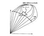
本発明の一実施形態に係る方法では、効果的にアンテナアレイを形成する少なくとも3つのアンテナ素子(受信装置、「RU」)によって受信されたトランスポンダ応答のTDOAデータに基づいてターゲットの方位角を計算する。ターゲットの距離が基線よりも非常に大きい場合には、方位角と仰角を計算する簡単な線形近似を使用することができる。距離のみまたは距離と高度が利用できる場合には、所与の距離と測定TDOAに最も適合する高度での方位角検索を行うことによって測定精度を大きく向上させることができる。 In a method according to an embodiment of the present invention, a target azimuth is calculated based on transponder response TDOA data received by at least three antenna elements (receiver, “RU”) effectively forming an antenna array. To do. If the target distance is much larger than the baseline, a simple linear approximation that calculates the azimuth and elevation can be used. If only distance or distance and altitude are available, the measurement accuracy can be greatly improved by performing an azimuth search at the altitude that best fits the given distance and measurement TDOA.
地上のRUによって受信される信号は、通常はターゲットである航空機のトランスポンダによって生成される。データが地上の送信器からの呼掛け信号に対する応答として受信された場合、メッセージの往復遅延を計算し、距離計算に使用するために保存する。 The signal received by the ground RU is typically generated by the target aircraft transponder. If data is received in response to an interrogation signal from a terrestrial transmitter, the round trip delay of the message is calculated and stored for use in distance calculations.
受信データはRUによって処理され、到着時間差(TDOA)の計算に使用される到着時間(TOA)情報が付加され、さらなる評価のために処理装置に送られる。処理装置は、各クラスタが所定のターゲットからの所定の送信情報(transmission)を表すクラスタにデータを分類し、評価して方位角の初期推定値を得る。次に、初期方位角の周辺で検索を行って非線型誤差を補償する。検索は、RTDデータから計算した距離とトランスポンダ応答内の高度データから計算した高度における初期方位角について円弧を作成することによって行われる。円弧の大きさは、アンテナ基線の大きさの約2倍に設定される。円弧に沿った所定数の点を評価のために選択し、各選択点はトランスポンダ返信信号から計算した同一のRTDを有する。 The received data is processed by the RU and appended with time-of-arrival (TOA) information that is used to calculate the time-of-arrival difference (TDOA) and sent to the processing unit for further evaluation. The processing device classifies data into clusters where each cluster represents predetermined transmission information from a predetermined target and evaluates to obtain an initial estimate of azimuth. Next, a search is performed around the initial azimuth to compensate for non-linear errors. The search is performed by creating an arc for the initial azimuth at the altitude calculated from the distance calculated from the RTD data and the altitude data in the transponder response. The size of the arc is set to about twice the size of the antenna baseline. A predetermined number of points along the arc are selected for evaluation, each selected point having the same RTD calculated from the transponder return signal.
円弧上の各選択点について予測TDOAを計算し、予測TDOAを測定TDOAと比較すると誤差が得られる。最小誤差を有する予測TDOAに関連付けられた方位角を、ターゲットのより正確な方位角として選択する。次に、得られたより正確な方位角とRTDデータを使用してターゲットのより正確な平面位置を計算する。 An error is obtained by calculating the predicted TDOA for each selected point on the arc and comparing the predicted TDOA with the measured TDOA. The azimuth angle associated with the predicted TDOA with the smallest error is selected as the more accurate azimuth angle of the target. The resulting more accurate azimuth and RTD data is then used to calculate a more accurate planar position of the target.
検索はより小さな円弧を使用して所定回数繰り返され、推定位置の精度を向上させる。距離が利用できない場合には、この方法では推定方位角と仰角のみを計算する。検索から最小誤差となる方位角を選択する。最後に、x,y位置を計算し、高度データから計算される場合には高度(z)を含める。 The search is repeated a predetermined number of times using smaller arcs to improve the accuracy of the estimated position. If the distance is not available, this method calculates only the estimated azimuth and elevation. Select the azimuth that gives the smallest error from the search. Finally, the x, y position is calculated, and if calculated from altitude data, the altitude (z) is included.
本発明の別の実施形態に係る方法は、上述したようにトランスポンダ信号が少なくとも3つの受信器によって受信された場合のTOA及びRTD情報を使用してターゲットの二次元推定位置を計算する。本実施形態によれば、ターゲットの高度は既知であり、z座標として使用してターゲットの推定位置の精度を向上させる。高度は、トランスポンダ信号に含まれるターゲットから供給された高度データを使用して計算でき、あるいはターゲットが地上にあるという判断から高度を得ることができる。本実施形態によれば、測定TOA、ターゲットの高度、計算距離をRUの座標とともにクローズド距離支援アルゴリズムに供給する。本発明のこの方法では、ターゲットの二次元(x,y)推定位置を計算し、高度をz座標として使用して三次元推定位置を得る。 A method according to another embodiment of the present invention uses the TOA and RTD information when a transponder signal is received by at least three receivers as described above to calculate a two-dimensional estimated position of the target. According to this embodiment, the altitude of the target is known and is used as the z coordinate to improve the accuracy of the estimated position of the target. The altitude can be calculated using altitude data supplied from the target included in the transponder signal, or the altitude can be obtained from a determination that the target is on the ground. According to this embodiment, the measurement TOA, the target altitude, and the calculation distance are supplied to the closed distance support algorithm together with the RU coordinates. In this method of the present invention, a two-dimensional (x, y) estimated position of the target is calculated and a three-dimensional estimated position is obtained using the altitude as the z coordinate.
次に、推定位置、ターゲットの高度、計算距離を検索に使用し、推定位置の精度をさらに向上させる。検索はターゲットの新しい推定位置を推定し、新しい推定位置に対応するTOAを計算する。検索は、元(現在)の推定位置のTOAと新しい推定位置のTOAとの間の誤差を計測するコスト関数をさらに含む。最小誤差をもたらす推定位置を新しい現在の推定位置として選択する。検索は、誤差が所定の最小値以下となるまで、最小誤差となる推定位置を新しい現在の推定位置として使用して繰り返される。 Next, the estimated position, the altitude of the target, and the calculated distance are used for the search to further improve the accuracy of the estimated position. The search estimates a new estimated position of the target and calculates a TOA corresponding to the new estimated position. The search further includes a cost function that measures an error between the TOA at the original (current) estimated position and the TOA at the new estimated position. The estimated position that yields the smallest error is selected as the new current estimated position. The search is repeated using the estimated position with the smallest error as the new current estimated position until the error is below a predetermined minimum value.
本発明のさらに別の実施形態に係る方法は、上述したようにトランスポンダ信号が少なくとも4つの受信器によって受信された場合のTOA及びRTD情報を使用してターゲットの三次元推定位置を計算する。本実施形態によれば、ターゲットの高度は未知である。従って、測定TOAと計算距離のみをRUの座標とともにクローズド距離支援アルゴリズムに供給する。この方法では、TOA及びRTDデータから直接ターゲットの三次元(x,y,z)推定位置を計算する。 A method according to yet another embodiment of the present invention uses the TOA and RTD information when the transponder signal is received by at least four receivers as described above to calculate a three-dimensional estimated position of the target. According to this embodiment, the altitude of the target is unknown. Therefore, only the measured TOA and the calculated distance are supplied to the closed distance support algorithm along with the RU coordinates. In this method, the three-dimensional (x, y, z) estimated position of the target is calculated directly from the TOA and RTD data.
次に、三次元推定位置と計算距離を使用して検索を行い、推定位置の精度をさらに向上させる。検索ではターゲットの新しい推定位置を推定し、新しい推定位置に対応するTOAを計算する。検索は、元(現在)の推定位置のTOAと新しい推定位置のTOAとの間の誤差を計測するコスト関数をさらに含む。最小誤差となる推定位置を新しい現在の推定位置として選択する。検索は、誤差が所定の最小値以下となるまで、最小誤差となる推定位置を新しい現在推定位置として使用して繰り返される。 Next, a search is performed using the three-dimensional estimated position and the calculated distance to further improve the accuracy of the estimated position. In the search, a new estimated position of the target is estimated, and a TOA corresponding to the new estimated position is calculated. The search further includes a cost function that measures an error between the TOA at the original (current) estimated position and the TOA at the new estimated position. The estimated position with the smallest error is selected as the new current estimated position. The search is repeated using the estimated position with the minimum error as the new current estimated position until the error is below a predetermined minimum value.
本発明の特徴及び目的のさらなる理解のために、添付図面を参照して本発明を実施するための好適な形態を以下に詳細に説明する。 For a further understanding of the features and objects of the present invention, preferred forms for carrying out the invention will now be described in detail with reference to the accompanying drawings.
以下、本発明の一実施形態を図1〜図9を参照して説明する。図1に示すように、複数のアンテナ素子1(以下「受信装置」(RU)という)が空港領域内の既知の位置に配置され、アンテナアレイを構成している。代表的なRUはセンシス社(Sensis Corporation)(型番100−008121−G001)から販売されている。RUの距離と配置は、アンテナアレイ基線(baseline)または基線と呼ぶ。本実施形態では、少なくとも1つの送信器と3つの受信器の組み合わせが空港内と空港周辺でのターゲットの三次元的な位置特定のために必要である。RUは、送信専用RU、受信専用RUまたは送受信RUであってもよい。空港内と空港周辺の地形と建物のレイアウトによっては、見通し線(Line of Sight;LOS)と多重通路の問題を解消するためにさらに多くのRUが必要な場合がある。本発明によれば、空港の領域内に全てのRUを配置することができ、メンテナンスとセキュリティが容易になると共に通信が簡素化される。好ましい実施形態では、送信アンテナ素子は1030MHzの位相変調アップリンク信号を送信することができ、受信アンテナ素子は1090MHzの振幅変調ダウンリンク信号を受信することができる。ただし、その他の信号も使用することができる。 Hereinafter, an embodiment of the present invention will be described with reference to FIGS. As shown in FIG. 1, a plurality of antenna elements 1 (hereinafter referred to as “receivers” (RU)) are arranged at known positions in the airport area to constitute an antenna array. A representative RU is sold by Sensis Corporation (model number 100-008121-G001). The distance and placement of RUs is referred to as the antenna array baseline or baseline. In this embodiment, a combination of at least one transmitter and three receivers is necessary for three-dimensional localization of the target in and around the airport. The RU may be a transmission-only RU, a reception-only RU, or a transmission / reception RU. Depending on the terrain and building layout in and around the airport, more RUs may be required to eliminate line of sight (LOS) and multipath problems. According to the present invention, all RUs can be arranged in the airport area, and maintenance and security are facilitated and communication is simplified. In a preferred embodiment, the transmit antenna element can transmit a 1030 MHz phase modulated uplink signal and the receive antenna element can receive a 1090 MHz amplitude modulated downlink signal. However, other signals can be used.
図2に示すように、各RU1は、ターゲットから受信した各トランスポンダ信号の到達時間(TOA)を正確に測定するTOA装置2を含む。RU1は、ローカルエリアネットワーク(LAN)等の通信手段によって、位置特定計算を行う処理装置3に接続されている。また、Rf(無線周波数)リンクや電話技術等の他の通信手段も使用することができ、本発明は通信手段によって限定されるものではない。 As shown in FIG. 2, each RU 1 includes a
ある意味では、図1に示すRUのレイアウトと図2に示す装置は、従来の多点計測技術を使用してターゲットの位置を特定するために採用されるものと同様である。しかし、上述したように、ターゲットの距離に関連付けられるGDOPは、ターゲットの距離に対するアンテナ基線(受信器間の距離)の比率が減少するに従ってかなり大きくなる。従って、「不確定の楕円」内でターゲットの位置を特定することはより困難になり、多点計測装置からターゲットまでの距離が増加するに従って多点計測装置の有効性は顕著に低下する。一方、本発明によれば、図1と図2に示すようなRUインフラの有効範囲を拡張するために距離支援位置アルゴリズム(range aided position algorithm)を使用し、以下に詳細に説明するように、装置から非常に離れたターゲットの位置を正確に特定する。 In a sense, the RU layout shown in FIG. 1 and the apparatus shown in FIG. 2 are similar to those employed to locate the target using conventional multipoint measurement techniques. However, as described above, the GDOP associated with the target distance increases considerably as the ratio of the antenna baseline (distance between the receivers) to the target distance decreases. Therefore, it becomes more difficult to specify the position of the target within the “indeterminate ellipse”, and the effectiveness of the multipoint measurement device is significantly reduced as the distance from the multipoint measurement device to the target increases. Meanwhile, according to the present invention, a range aided position algorithm is used to extend the effective range of the RU infrastructure as shown in FIGS. 1 and 2, as described in detail below. Accurately locate the target very far from the device.
図3は、送受信RU4と、ターゲット5と、2つの受信RU6との間の信号の流れを示す。送受信RU4は呼掛け信号7を送り、ターゲット5のトランスポンダからの応答8を要求する。送受信RU4は、ターゲットの距離を計算する際に使用するために呼掛け信号7の送信時間を記録する。ターゲット内のトランスポンダは、後述するように許容範囲の既知の時間(内部遅延)内で自動的に応答する。返信信号はRU4,6,6によって受信され、データが解読され、TOA装置2からの到達時間(TOA)が追加される。グローバルポジショニング装置(GPS)データ、局所的時計、内部カウンタなどの様々な方法を、TOAを決定するために使用することができるが、本発明はそれらに限定されるものではない。トランスポンダの返信信号は、航空交通管制官が使用するための豊富な情報を含んでいる。このような情報としては、要求された応答の種類に応じてモードSアドレス、飛行識別番号、高度データが挙げられるが、本発明はそれらに限定されるものではない。次に、各RUは、更なる評価のためにタイムスタンプを含むデータを、データリンクを介して処理装置3に送信する。また、送受信RU4は呼掛け信号7の送信時間を、データリンクを介して処理装置3に送信する。 FIG. 3 shows a signal flow among the transmission / reception RU 4, the
処理装置は解読データをクラスタ化し、各クラスタは所定のターゲットから各RUが受信した所定の送信情報を含む。クラスタ化(clustering)は、ターゲット識別番号、モードSアドレスまたはモード3/Aコードによって通常は行うが、その他の証明された方法も利用することができる。以下に詳細に説明するように、処理装置はRUから供給されたターゲットデータと記録された呼掛け信号の送信時間を利用して計算を行い、ターゲットの正確な位置を決定する。 The processing device clusters the decrypted data, and each cluster includes predetermined transmission information received by each RU from a predetermined target. Clustering is usually done by target identification number, mode S address or
送受信RU4からターゲットに呼掛け信号が送信された時間は、ターゲットのトランスポンダの内部遅延及び送受信RU4でのターゲットの返信信号の到達時間と共に既知である。このデータは、往復遅延を計算してターゲットの正確な距離を決定するために使用される。好ましい実施形態では、距離計算に使用される信号を送受信するために同一のアンテナを使用する。このようにして、往復遅延データのみに基づいてターゲットとなる航空機の正確な距離を下記式によって計算することができる。 The time when the interrogation signal is transmitted from the transmission / reception RU 4 to the target is known together with the internal delay of the target transponder and the arrival time of the return signal of the target at the transmission / reception RU 4. This data is used to calculate the round trip delay to determine the exact distance of the target. In the preferred embodiment, the same antenna is used to transmit and receive signals used for distance calculation. In this way, the exact distance of the target aircraft can be calculated by the following formula based only on the round trip delay data.

式中、Rは距離であり、RTDは往復遅延(呼掛け信号の送信から返信信号の受信までの経過時間)であり、delayはターゲットのトランスポンダの内部遅延であり、cは光速である。In the equation, R is a distance, RTD is a round trip delay (elapsed time from transmission of an interrogation signal to reception of a return signal), delay is an internal delay of the target transponder, and c is the speed of light.
別の実施形態では、図4に示すように、送信RU40を3つの受信RU60と組み合わせて使用することができる(すなわち、信号の送受信は同一のアンテナを介して行われない)。本実施形態を採用する場合、ターゲットの方位角を計算した後でなければターゲットの正確な距離は分からない。すなわち、往復遅延は送信RU40のアンテナから受信RU60の1つのアンテナまでにおいて測定されるため、ターゲットの方位角が計算されるまではターゲットの正確な距離は分からない。ただし、図3と図4に示すシナリオでは、距離が往復遅延データから計算されるため、従来技術の多点計測技術に関連するGDOPの問題を解消することができ、RUインフラに変更を加えることなく距離精度が劇的に向上する(例えば、空港外の20マイルを超える距離)。 In another embodiment, as shown in FIG. 4, a transmit
なお、ターゲットの距離を計算するために往復遅延を単独(図3)またはターゲットの方位角と組み合わせて(図4)使用することは、方法の一工程に過ぎない。次の工程では、各ターゲットに対してクラスタ化TDOAデータを使用することが必要である。すなわち、同一のクラスタに属するトランスポンダ応答間のTDOAは、時間的バイアスを効果的に排除する基準としての1つのRUからのTOAを利用することで計算される。これらのTDOAを測定TDOAと呼ぶ。次に、線形近似を使用して測定TDOAをRUの既知の位置と関連して評価することによって方位角の第1の近似値を計算する。 Note that using the round trip delay alone (FIG. 3) or in combination with the azimuth of the target (FIG. 4) to calculate the target distance is only one step of the method. In the next step, it is necessary to use clustered TDOA data for each target. That is, the TDOA between transponder responses belonging to the same cluster is calculated using the TOA from one RU as a criterion to effectively eliminate the time bias. These TDOAs are called measured TDOAs. A first approximation of the azimuth is then calculated by evaluating the measured TDOA relative to the known location of the RU using a linear approximation.
さらに、測定範囲及び高度における測定TDOAと最も一致する方位角の第1の近似値付近での方位角検索によってデータの精度をさらに向上させる。高度は、従来技術で知られているようにトランスポンダ応答に含まれる高度データから計算する。図5に示すように、トランスポンダ応答(返信信号)からの高度データから決定した高度と距離における方位角の第1の近似値について円弧9を生成する。本発明の好ましい実施形態(図3)では、検索を非常に簡素化するように、(往復遅延に基づく)距離計算に使用するために呼掛け信号を送信し、トランスポンダ返信信号を受信するために同一のアンテナが利用されているため、生成された円弧は円の一部を示す。呼掛け信号を送信し、トランスポンダ返信信号を受信するために異なるアンテナを利用した場合(図4)には、円弧は楕円の一部を示すことになる。この場合には検索アルゴリズムが多少複雑になるが、全くあるいはほとんど精度を低下させることなく検索を行うことができる。 Further, the accuracy of the data is further improved by searching for the azimuth angle near the first approximate value of the azimuth angle that most closely matches the measured TDOA at the measurement range and altitude. The altitude is calculated from altitude data contained in the transponder response as is known in the prior art. As shown in FIG. 5, an
例えば、円弧はアンテナ基線(最も離れた2つのRU間の距離)の大きさの約2倍(実質的に2倍)となるように選択し、それぞれが返信信号から計算した場合に同じ往復遅延(RTD)を有する10個の点(方位角)10を円弧9に沿って設定する。検索時の各方位角点について、TDOAを後述する公知のモデルから計算する。これらのTDOAを予測TDOAと呼ぶ。次に、予測TDOAと測定TDOAとの最小誤差を計算する。図6に示すように、最小誤差11となる予測TDOAに関連付けられた方位角を選択する。好ましくは、円弧は新しい方位角を中心として原寸の10分の1まで縮小し、第2の群の新しい10個の点を小さな円弧上に設定する。このプロセスは、例えばアンテナ基線サイズ及びアンテナの距離精度を含む装置パラメータに基づいて所定回数繰り返す。繰り返し数は所与の装置に特有であり、装置の展開時に決定する。 For example, the arc is selected to be approximately twice (substantially twice) the size of the antenna baseline (the distance between the two most distant RUs), and the same round trip delay when each is calculated from the return signal Ten points (azimuth angles) 10 having (RTD) are set along the
往復遅延データから正確な範囲を決定し、トランスポンダ応答によって得られる高度データから高度を計算しているため、検索は一次元で行われ、多点計測検索と比較して複雑さをかなり減少させることができる。最速降下法(Steepest Rate of Descent techniques)などの他の検索評価方法を使用しても同様の精度の結果を得ることができる。 Since the exact range is determined from the round trip delay data and the altitude is calculated from the altitude data obtained by the transponder response, the search is done in one dimension and significantly reduces the complexity compared to the multipoint measurement search Can do. Similar results can be obtained using other search evaluation methods such as the fastest descent method (Step of Rate of Descent Techniques).
次に、最終的に計算した方位角と距離及びトランスポンダの返信信号の高度データから計算した高度からx,y,z座標を決定し、ターゲットの正確な三次元位置を特定する。このデータは、航空管制オペレータに対して表示することができる。 Next, x, y, and z coordinates are determined from the altitude calculated from the finally calculated azimuth and distance and altitude data of the response signal of the transponder, and an accurate three-dimensional position of the target is specified. This data can be displayed to the air traffic control operator.
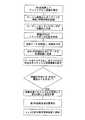
図7は、本実施形態に係る工程のフロー図である。第1の工程は、好ましくは空港の領域内に複数のアンテナ素子を配置することである。好ましい実施形態では、アンテナ素子の少なくとも1つは信号を送受信し(送受信RU)、その他のアンテナ素子は受信専用RUであってもよい。 FIG. 7 is a flowchart of the steps according to the present embodiment. The first step is preferably arranging a plurality of antenna elements in the area of the airport. In a preferred embodiment, at least one of the antenna elements transmits and receives signals (transmit / receive RU), and the other antenna elements may be receive-only RUs.
送受信RUは信号をターゲットに送信し、ターゲットは既知のデータ(例えば、航空機ID、高度など)を含む返信信号を送信する。返信信号は、呼掛け信号を送信した送受信RUのアンテナまたは別のRUのアンテナを介して受信される。また、返信信号は少なくとも2つの他のRUにも受信される。受信データは解読されてTOA情報が付加され、次に処理装置3に送信され、クラスタ化されると共にターゲットの距離と初期(ほぼ正確な)方位角を計算するために利用される。 The transmission / reception RU transmits a signal to the target, and the target transmits a return signal including known data (for example, aircraft ID, altitude, etc.). The reply signal is received via the antenna of the transmission / reception RU that transmitted the interrogation signal or the antenna of another RU. The return signal is also received by at least two other RUs. The received data is decrypted and appended with TOA information, then transmitted to the
図3に示す好ましい実施形態によれば、返信信号は呼掛け信号を送信したアンテナを介して受信され、ターゲットの正確な距離を得るために往復遅延を使用することができる。次に、測定TDOAを計算・評価してターゲットの初期方位角を決定し、初期方位角の周囲で検索を実行して非線型誤差を補償する。検索は、装置パラメータに基づいて所定回数繰り返される。次に、ターゲットの正確な三次元位置を決定する(ターゲットの高度はターゲットからの返信信号に含まれる高度データによって決定する)。 According to the preferred embodiment shown in FIG. 3, the return signal is received via the antenna that transmitted the interrogation signal and a round trip delay can be used to obtain the exact distance of the target. Next, the measured TDOA is calculated and evaluated to determine the initial azimuth of the target and a search is performed around the initial azimuth to compensate for non-linear errors. The search is repeated a predetermined number of times based on the device parameters. Next, an accurate three-dimensional position of the target is determined (the altitude of the target is determined by altitude data included in a return signal from the target).
本実施形態によれば、ターゲットの初期(ほぼ正確な)方位角を決定するために特定のアルゴリズムを使用する。初期方位角周辺で検索を実行し、ターゲットのより正確な方位角を得るためには別の特定のアルゴリズムを使用する。それらのアルゴリズムを開発した方法を以下に説明する。 According to this embodiment, a specific algorithm is used to determine the initial (almost accurate) azimuth of the target. Another specific algorithm is used to perform a search around the initial azimuth and to obtain a more accurate azimuth of the target. The method of developing these algorithms is described below.
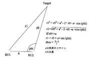
図8に、2つのRUによる返信信号受信の幾何学的表現を示す。測定TDOAのための正確な式は、コサイン定理を利用して以下のように導かれる。 FIG. 8 shows a geometric representation of response signal reception by two RUs. The exact formula for the measured TDOA is derived as follows using the cosine theorem.
テイラー級数に展開すると、a≪r0について一次式が得られる。 When expanded to the Taylor series, a linear expression is obtained for a << r0.
なお、r1−r0はターゲットと各RUとの距離の差を表す。変数uは、簡単な代数演算を使用して測定TDOAから直接計算することができる。 R1-r0 represents the difference in distance between the target and each RU. The variable u can be calculated directly from the measured TDOA using a simple algebraic operation.
(式中、uは角度phiのコサインであり、cは光速である。)
図9に示す座標系を使用することによって、この近似値は以下のように三次元に拡張される。(Where u is the cosine of the angle phi and c is the speed of light.)
By using the coordinate system shown in FIG. 9, this approximate value is extended to three dimensions as follows.
式中、rlはターゲットからRUまでの正確な距離であり、(x,y,z)はターゲットの座標であり、(x1,y1,z1)は受信RUの座標である。Where rl is the exact distance from the target to the RU, (x, y, z) are the coordinates of the target, and (x1, y1, z1) are the coordinates of the receiving RU.
原点からのターゲットの距離はr0と表される。 The distance of the target from the origin is represented as r0.
r0≫(x1,y1,z1)の場合、適切なテイラー級数からの一次展開近似値は以下のように表される。 In the case of r0 >> (x1, y1, z1), a first-order expansion approximation value from an appropriate Taylor series is expressed as follows.
(式中、azとelはそれぞれ方位角と仰角である。)
従って、距離の式は次のようになる。(In the formula, az and el are an azimuth angle and an elevation angle, respectively.)
Therefore, the equation for distance is as follows.
当業者には明らかなように、テイラー級数の一次部分のみを評価すると非線型誤差が引き起こされるが、許容できる方位角の一次近似値を得ることができる。これらの誤差の影響は、詳細を後述する検索によって緩和される。 As will be apparent to those skilled in the art, evaluating only the primary part of the Taylor series causes non-linear errors, but an acceptable first order approximation of azimuth can be obtained. The influence of these errors is mitigated by a search described in detail later.
各受信器(RU)へのTOAは以下のように表される。 The TOA to each receiver (RU) is expressed as follows:
測定TOAは時刻と完全に相対的ではないため、TOAバイアスが存在する。 Since the measured TOA is not completely relative to the time, there is a TOA bias.
複数の受信器を使用することによって、前記式は行列に一般化することができる。 By using multiple receivers, the equation can be generalized to a matrix.
または、短い表記法では以下のようになる。 Or in short notation:
(ru_mat_fullは全受信器の位置を含む)
(u_matは正弦空間の方向ベクトルである)
TOAバイアスは全受信器に共通である。従って、1つのRUを基準とし、他の全てのRUのTOAから基準RUのTOAを減算することによってTOAバイアスを排除でき、測定TDOAが決定される。データを供給する第1のRUを基準RUとして通常選択するが、任意のRUを使用することもできる。
従って、関連行列式は以下のようになる。(Ru_mat_full contains the location of all receivers)
(U_mat is a sine space direction vector)
The TOA bias is common to all receivers. Therefore, the TOA bias can be eliminated by subtracting the TOA of the reference RU from the TOA of all other RUs with one RU as the reference, and the measured TDOA is determined. The first RU that supplies the data is typically selected as the reference RU, but any RU can be used.
Thus, the related determinant is
式中、(9.1)TDOA1=TOA2−TOA1, TDOA2=TOA3−TOA1,....,TDOAn−1=TOAn−TOA1
変数wは以下の式に従ってu,vに依存する。(9.1) TDOA1 = TOA2-TOA1, TDOA2 = TOA3-TOA1,. . . . , TDOAn-1 = TOAn-TOA1
The variable w depends on u and v according to the following equation:
従って、u,vのみを求めれば十分であり、式(9)は以下のように変形することができる。 Therefore, it is sufficient to obtain only u and v, and Equation (9) can be modified as follows.
式(11)は、以下のように簡潔に記述することができる。 Equation (11) can be described briefly as follows.
式(12)の最適な推定解(MMSEまたはML)は以下のように表される。 The optimal estimated solution (MMSE or ML) of Expression (12) is expressed as follows.
正弦空間における方向ベクトルはRU位置と測定TDOAベクトルに依存し、初期方位角を与える固定行列の乗法である。 The direction vector in sine space depends on the RU position and the measured TDOA vector, and is a fixed matrix multiplication that gives the initial azimuth.
なお、式(11)は受信器のz座標を無視している。これは、式の一次性を維持するためである。受信器からターゲットへの距離に対するzの寄与はx,yと比較して無視できるものである。なお、アルゴリズムのその後の工程がzを補償する。 Note that equation (11) ignores the z-coordinate of the receiver. This is to maintain the primary nature of the equation. The contribution of z to the distance from the receiver to the target is negligible compared to x and y. Note that subsequent steps in the algorithm compensate for z.
方位角における一次元の最適化検索を実行することによって非線型誤差が補償される。検索は、トランスポンダの返信信号からの高度データから計算した距離と高度における方位角の第1の近似値について円弧を作成することによって行われる。円弧の所定数の点を評価のために選択し、各選択点はトランスポンダ返信信号から計算した同じ往復遅延(RTD)を有する。距離と高度はトランスポンダ返信信号によって与えられるため、距離と高度は一定であるものとする。高度を利用することができない場合には、高度を0に設定し、アルゴリズムによってxy面での推定座標を求める。 Non-linear errors are compensated by performing a one-dimensional optimization search in azimuth. The search is performed by creating an arc for the first approximate value of the azimuth at the distance and altitude calculated from the altitude data from the reply signal of the transponder. A predetermined number of points on the arc are selected for evaluation, each selected point having the same round trip delay (RTD) calculated from the transponder return signal. Since the distance and altitude are given by the transponder reply signal, the distance and altitude are assumed to be constant. If the altitude cannot be used, the altitude is set to 0 and the estimated coordinates on the xy plane are obtained by the algorithm.
検索を行うために、各方位角の予測TDOAを図9に示す公知のモデルから以下のように計算する。
1.円弧の選択された点のx,y,zを、同一のアンテナを使用する送受信器の場合には一定のRTDを有する円、送信器と受信器が異なるアンテナを使用する場合には一定のRTDを有する楕円を想定して簡単な三角方程式を使用して計算する。
2.各RUへの距離を、円弧上で既に計算したx,y,zと選択されたRUの既知のx1,y1,z1を使用して計算する。この工程は各RUについて繰り返す。
3.各RUでの予測TOAを、距離を光速(c)で除算することによって計算する。
4.基準RU(基準RUは測定TDOAを計算するために選択したRUと同一である)のTOAを各RUのTOAから減算する。
5.得られた結果は検索を評価する際に使用される予測TDOAベクトルである。In order to perform the search, the predicted TDOA of each azimuth is calculated from the known model shown in FIG. 9 as follows.
1. The x, y, z of the selected point of the arc is a circle with a constant RTD in the case of a transceiver using the same antenna, or a constant RTD when the transmitter and receiver use different antennas. Calculating using a simple trigonometric equation assuming an ellipse with
2. The distance to each RU is calculated using x, y, z already calculated on the arc and the known x1, y1, z1 of the selected RU. This process is repeated for each RU.
3. The predicted TOA at each RU is calculated by dividing the distance by the speed of light (c).
4). Subtract the TOA of the reference RU (the reference RU is the same as the RU selected to calculate the measured TDOA) from the TOA of each RU.
5). The result obtained is a predicted TDOA vector used in evaluating the search.
次に、以下のコスト関数(cost function)を方位角検索について評価する。 Next, the following cost function is evaluated for azimuth search.
式中、tdoa_measjはRU#jの測定TDOAであり、tdoa_expected(azij,R,H)はRU#jの方位角における予測TDOAである。Where tdoa_measj is the measured TDOA of RU # j and tdoa_expected (azij , R, H) is the predicted TDOA at the azimuth angle of RU # j.
距離Rと高度Hは、トランスポンダ返信信号から導かれた情報と等しく一定に維持される。関数はi点(例えば10)について計算し、各点はトランスポンダ返信信号から計算した同一の往復遅延(RTD)を有し、最小誤差を与える予測TDOAに関連付けられた方位角を選択する。高度を利用することができない場合には、高度を0に設定し、アルゴリズムによってxy平面での推定座標を求める。検索は、新しい方位角(すなわち、最小誤差を与えた方位角)に関してより小さな円弧(例えば、元の円弧の1/10の大きさ)を作成することによって繰り返す。次に、コスト関数を第2のi点(例えば10点)で繰り返す。再び、最小誤差となる予測TDOAに関連付けられた方位角を選択する。この検索プロセスは上述したように所定回数繰り返し、最終方位角はコスト関数から最小TDOA誤差を与える。 The distance R and altitude H are kept constant and equal to the information derived from the transponder return signal. The function calculates for i points (eg 10), each point has the same round trip delay (RTD) calculated from the transponder return signal, and selects the azimuth angle associated with the predicted TDOA that gives the smallest error. When the altitude cannot be used, the altitude is set to 0 and the estimated coordinates on the xy plane are obtained by the algorithm. The search is repeated by creating a smaller arc (eg, 1/10 the size of the original arc) for the new azimuth (ie, the azimuth that gave the smallest error). Next, the cost function is repeated at a second i point (for example, 10 points). Again, the azimuth angle associated with the predicted TDOA that results in the smallest error is selected. This search process is repeated a predetermined number of times as described above, and the final azimuth gives the minimum TDOA error from the cost function.
RTDデータから計算された距離を高度で除算し、得られた結果の逆正弦を取るとターゲットの仰角が得られる。仰角と最適方位角が決定されると、三次元座標は以下の通り計算される。 Dividing the distance calculated from the RTD data by the altitude and taking the arc sine of the result, the elevation angle of the target is obtained. Once the elevation and optimum azimuth are determined, the three-dimensional coordinates are calculated as follows:
式中、Rは測定距離であり、az_cは検索プロセスによって計算された最適方位角であり、Heightはトランスポンダ応答の高度データから計算した値である。Where R is the measured distance, az_c is the optimal azimuth calculated by the search process, and Height is the value calculated from the altitude data of the transponder response.
トランスポンダ応答から高度を計算することができない場合には、高度を0に設定し、x,y座標のみを計算する。 If the altitude cannot be calculated from the transponder response, the altitude is set to 0 and only the x and y coordinates are calculated.
RUからの呼掛けに応答するものではないトランスポンダ信号を受信した場合には、RTD情報から距離を決定することができない。このシナリオでは高度が得られない場合があり、ターゲットからの信号は高度データを含まない。高度と距離が利用できない場合には、この方法では式(13)から直接ほぼ正確な方位角と仰角を計算する。精度はアンテナ基線と距離の比率に依存し、距離が増加すると向上する。別の近似値はアンテナアレイのz次元である。アンテナアレイのz次元が基線と相対的に減少すると、近似値の精度は向上する。 When a transponder signal that does not respond to a call from the RU is received, the distance cannot be determined from the RTD information. In this scenario, altitude may not be obtained and the signal from the target does not contain altitude data. If the altitude and distance are not available, this method calculates the nearly accurate azimuth and elevation directly from equation (13). The accuracy depends on the ratio of the antenna base line to the distance and improves as the distance increases. Another approximation is the z dimension of the antenna array. As the z dimension of the antenna array decreases relative to the baseline, the accuracy of the approximate value improves.
1つのRUをレーダー送信機として使用し、複数のRUをレーダー受信機として使用すれば、レーダーによるターゲットの位置特定のために同じ方法を採用することができる。上述したように、TDOA情報からの往復遅延と方位角から距離を計算することができる。 If one RU is used as a radar transmitter and multiple RUs are used as radar receivers, the same method can be employed for target location by the radar. As described above, the distance can be calculated from the round trip delay and the azimuth angle from the TDOA information.
本発明の別の実施形態を図1〜図3及び図10を参照して説明する。第1の実施形態では、複数のRUを図1に示すように空港の領域内の既知の位置に配置し、少なくとも1つの送信器と3つの受信器の組み合わせが空港内と空港周辺でのターゲットの三次元的な位置特定のために必要であり、RUは送信専用RU、受信専用RUまたは送受信RUであってもよい。 Another embodiment of the present invention will be described with reference to FIGS. In the first embodiment, a plurality of RUs are arranged at known positions in the area of an airport as shown in FIG. 1, and a combination of at least one transmitter and three receivers is a target in and around the airport. The RU may be a transmission-only RU, a reception-only RU, or a transmission / reception RU.
第1の実施形態と同様に、各RUは、ターゲットから受信した各トランスポンダ信号の到達時間(TOA)の正確なタイムスタンプを供給するTOA装置2を含む。複数のRU1は、通信手段によって処理装置3に接続されている。送受信器RU4と、ターゲット5と、2つの受信器RU6との間の信号フローは図3に示す通りである。送受信器RU4は呼掛け信号7を送り、ターゲット5のトランスポンダからの応答8を要求する。送受信器RU4は、ターゲットの距離を計算する際に使用するために呼掛け信号7の送信時間を記録する。ターゲット内のトランスポンダは、後述するように許容範囲の既知の時間内で自動的に応答する。返信信号はRU4,6,6によって受信され、データが解読され、TOA装置2からの到達時間(TOA)が追加される。次に、各RUは、更なる評価のためにタイムスタンプを含むデータを、データリンクを介して処理装置3に送信する。また、送受信器RU4は呼掛け信号7の送信時間を、データリンクを介して処理装置3に送信する。 Similar to the first embodiment, each RU includes a
処理装置は解読データをクラスタ化し、各クラスタは所定のターゲットから各RUが受信した所定の送信情報を含む。クラスタ化は、ターゲット番号識別、モードSアドレスまたはモード3/Aコードによって通常は行うが、その他の証明された方法も利用することができる。以下に詳細に説明するように、処理装置はRUから供給されたターゲットデータと呼掛け信号の記録送信時間を利用して計算を行い、ターゲットの正確な位置を決定する。 The processing device clusters the decrypted data, and each cluster includes predetermined transmission information received by each RU from a predetermined target. Clustering is usually done by target number identification, mode S address or
ターゲットの高度が既知である場合には、ターゲットの二次元(x,y)推定位置を計算でき、高度をz座標として使用して三次元推定位置を得る。高度は、トランスポンダ返信信号内のターゲットによって供給された高度データから計算でき、あるいはターゲットが地上にあるという判断によって高度を知ることができる。いずれの場合でも、与えられた高度をz座標を供給するために使用するため、本実施形態の距離支援アルゴリズムの最終結果はターゲットの正確なx,y,z位置である。 If the altitude of the target is known, the two-dimensional (x, y) estimated position of the target can be calculated and the altitude is used as the z-coordinate to obtain a three-dimensional estimated position. The altitude can be calculated from the altitude data supplied by the target in the transponder reply signal, or the altitude can be known by determining that the target is on the ground. In any case, since the given altitude is used to supply the z-coordinate, the final result of the distance assistance algorithm of this embodiment is the exact x, y, z position of the target.
次の工程は、ターゲットの距離を推定位置計算に使用することができるか否かを決定することである。距離は先に開示した距離式によって計算する。計算した距離を使用できるか否かを決定するために距離閾値チェックを行う。距離閾値チェックは、ターゲットのトランスポンダによる呼掛け信号7の信号処理時間のばらつきのために必要となる。返信信号を生成するトランスポンダの処理時間には±0.5μ秒の許容差が適用され、誤差の範囲は約250フィートである。これらの誤差は空港から離れるに従って無視できるようになるが、ターゲットが近い場合には、誤差とターゲットの距離との比率のためにこれらの誤差は非常に大きくなる。従って、ターゲットが空港の所定の領域内にある場合には、RTDデータから計算された距離を使用せずにターゲットの位置を計算することが望ましい。距離閾値は装置展開時に決定し、処理装置3に供給される。 The next step is to determine whether the target distance can be used for the estimated position calculation. The distance is calculated by the distance formula disclosed above. A distance threshold check is performed to determine if the calculated distance can be used. The distance threshold check is necessary due to variations in the signal processing time of the
RTDデータから計算された距離を使用してターゲットの二次元位置を決定するために、信号を受信したRUの座標、測定TOA、与えられた高度、計算された距離、距離測定RUを、本発明の二次元クローズド距離支援アルゴリズムに入力する。二次元クローズド距離支援アルゴリズムは、与えられた高度をz座標として使用するx,y,z座標として、デカルト座標系におけるターゲットの位置を推定する。 In order to determine the two-dimensional position of the target using the distance calculated from the RTD data, the coordinates of the RU that received the signal, the measurement TOA, the given altitude, the calculated distance, the distance measurement RU To the two-dimensional closed distance support algorithm. The two-dimensional closed distance support algorithm estimates the target position in the Cartesian coordinate system as x, y, z coordinates using a given altitude as the z coordinate.
アルゴリズムは最初にRU座標とTOAを求め、距離測定RUとしてアルゴリズム内のRU1を設定する。次に、推定位置を計算するために使用される到達時間差(TDOA)を計算するために、その他のRUからのTOAをRU1のTOAから減算する。次に、RU1がデカルト座標系の原点に存在するようにRUの座標を変換し、他のRUから新しい原点(RU1)までの距離を計算する。RUの位置の値の行列を作成し、TDOAとRU距離を結合する新しいベクトルを計算し、推定位置が直接得られる。この時点での推定位置はRU1を原点とするデカルト座標系にあり、与えられた高度をz座標とするx,y,zでのターゲットの最終推定位置を得るためには系中心を原点とする元のデカルト座標系に変換し直すことが必要である。The algorithm first determines the RU coordinates and TOA, and sets RU1 in the algorithm as the distance measurement RU. Next, the TOA from the other RUs is subtracted from the RU1 TOA to calculate the time difference of arrival (TDOA) used to calculate the estimated position. Next, the coordinates of the RU are converted so that RU1 exists at the origin of the Cartesian coordinate system, and the distance from another RU to the new origin (RU1 ) is calculated. A matrix of RU position values is created and a new vector that combines the TDOA and RU distances is calculated and the estimated position is obtained directly. The estimated position at this point is in the Cartesian coordinate system with RU1 as the origin, and in order to obtain the final estimated position of the target at x, y, z with the given altitude as the z coordinate, the system center is the origin. It is necessary to convert back to the original Cartesian coordinate system.
最尤位置推定アルゴリズムの一例である二次元クローズド距離支援アルゴリズムからの推定位置は、MLE(Maximum Likehood Position algorithm:最尤位置推定)距離支援アルゴリズムによってさらに向上させる。二次元MLE距離支援アルゴリズムは、入力として、ターゲットの初期推定位置(高度をz座標として使用)、RUの座標、関連する測定TOA、距離測定値、距離測定RU(RU1)を必要とする。二次元MLE距離支援アルゴリズムは、連続的に新しい推定位置を推定し、新しい推定位置に対応する予測TOAを計算する反復解法である。二次元MLE距離支援アルゴリズムは、計算TOAと測定TOAとの間の誤差を測定するコスト関数をさらに含む。推定位置計算の場合には、コスト関数は、推定位置に対応する予測TOAと測定TOAとの間の標準になるように定義され、さらに詳しく後述するように距離計測が含まれる。最尤位置推定アルゴリズムとして、ニュートン−ラフソン法(Newton−Raphson Method)や滑降シンプレックス法(Simplex Downhill Method)等の他の検索評価方法を使用しても同様の精度の結果を得ることができる。The estimated position from the two-dimensional closed distance support algorithm, which is an example of the maximum likelihood position estimation algorithm, is further improved by an MLE (Maximum Like Position Position algorithm) distance support algorithm. The two-dimensional MLE distance support algorithm requires as input the initial estimated position of the target (using altitude as the z coordinate), the coordinates of the RU, the associated measurement TOA, the distance measurement, and the distance measurement RU (RU1 ). The two-dimensional MLE distance support algorithm is an iterative solution that continuously estimates new estimated positions and calculates a predicted TOA corresponding to the new estimated positions. The two-dimensional MLE distance assistance algorithm further includes a cost function that measures an error between the calculated TOA and the measured TOA. In the case of estimated position calculation, the cost function is defined to be a standard between the predicted TOA and the measured TOA corresponding to the estimated position, and includes distance measurement as described in more detail below. Similar search results can be obtained by using other search evaluation methods such as the Newton-Raphson method or the Downhill Simplex method as the maximum likelihood position estimation algorithm.
図10は、本実施形態に係る工程のフロー図である。第1の工程は、好ましくは空港の領域内に複数のアンテナ素子(RU)を配置することである。アンテナ素子の少なくとも1つは信号を送受信することができなければならず(送受信RU)、その他のアンテナ素子は受信専用RUであってもよい。 FIG. 10 is a flowchart of the steps according to the present embodiment. The first step is to place a plurality of antenna elements (RU), preferably in the area of the airport. At least one of the antenna elements must be able to transmit and receive signals (transmission / reception RU), and the other antenna elements may be reception-only RUs.
送受信RUは呼掛け信号をターゲットに送信し、送信時間を記録する。ターゲットのトランスポンダは、既知のデータ(例えば、モードSアドレス、航空機ID、高度など)を含む返信信号を送信する。呼掛け信号を送信した送受信RUと見通し線または多重通路の問題にさらされていない少なくとも2つの他のRUが応答を受信する。受信データは解読され、TOA情報が付加される。受信データ、TOA、記録された呼掛け信号の送信時間は処理装置3に送信される。処理装置3は、クラスタが複数のRUによって受信された同一のターゲットによる1回の送信からの情報を含むようにターゲットデータをクラスタ化する。 The transmission / reception RU transmits an interrogation signal to the target and records the transmission time. The target transponder transmits a return signal including known data (eg, mode S address, aircraft ID, altitude, etc.). The transmitting / receiving RU that transmitted the interrogation signal and at least two other RUs that are not exposed to line-of-sight or multipath problems receive the response. The received data is decrypted and TOA information is added. The transmission time of the received data, the TOA, and the recorded interrogation signal is transmitted to the
二次元推定位置を計算するために、RTDデータから計算された距離を推定位置の精度を向上させるために利用するか否かについて決定する。距離を計算に利用すると決定した場合には、本発明の二次元クローズド距離支援アルゴリズムを使用して二次元推定位置を計算する。計算された二次元推定位置は、上述したように与えられた高度をz座標として使用した二次元MLE距離支援アルゴリズムによってさらに精度を向上させる。 In order to calculate the two-dimensional estimated position, it is determined whether to use the distance calculated from the RTD data to improve the accuracy of the estimated position. If it is determined that the distance is used for the calculation, the two-dimensional estimated position is calculated using the two-dimensional closed distance support algorithm of the present invention. The calculated two-dimensional estimated position is further improved in accuracy by a two-dimensional MLE distance support algorithm using the given altitude as the z coordinate as described above.
以下、二次元距離支援アルゴリズムについて詳細に説明する。 Hereinafter, the two-dimensional distance support algorithm will be described in detail.
二次元クローズド距離支援アルゴリズム
二次元クローズド距離支援アルゴリズムの入力は以下の通りである。
・RU座標
・測定TOA
・ターゲット位置のZ成分z’
・測定距離(R)
・距離測定RU(RUr)
二次元クローズド距離支援アルゴリズムの出力は、ターゲットの位置の推定値である。Two-dimensional closed distance support algorithm The input of the two-dimensional closed distance support algorithm is as follows.
・ RU coordinates ・ Measurement TOA
・ Z component z 'of target position
・ Measurement distance (R)
・ Distance measurement RU (RUr )
The output of the two-dimensional closed distance assistance algorithm is an estimate of the target position.
第1の工程は、アルゴリズムにおいて距離測定RUがRU1となるようにRU座標とTOAを求めることである。次の工程は、第1のTOA(RU1からのTOA)を使用してTDOAを計算することである。The first step is to determine the RU coordinates and TOA so that the distance measurement RU is RU1 in the algorithm. The next step is to calculate TDOA using the first TOA (TOA from RU1 ).
次に、RU1が原点となるようにRU座標を変換する。Next, RU coordinates are converted so that RU1 is the origin.
次に、変換した座標系におけるRUから原点までの距離を計算する。 Next, the distance from the RU to the origin in the converted coordinate system is calculated.
次に、RU座標値の行列を作成する。 Next, a matrix of RU coordinate values is created.
なお、行列の成分は後にAijと言及し、(i,j)は行と列である。Note that the matrix component is referred to later as Aij, and (i, j) is a row and a column.
次に、TDOAとRU距離を結合する新しいベクトルを作成する。 Next, a new vector is created that combines the TDOA and RU distances.
そして、ターゲットの二次元推定位置を計算する。 Then, the two-dimensional estimated position of the target is calculated.
RUの座標はプロセスの開始時にRU1が原点となるように変換している。従って、最終推定位置を得るために推定位置を元の座標系に変換することが必要である。The coordinates of RU are transformed so that RU1 is the origin at the start of the process. Therefore, it is necessary to convert the estimated position to the original coordinate system in order to obtain the final estimated position.
二次元クローズド距離支援アルゴリズムの出力は推定位置(xi,yi,zi)である。The output of the two-dimensional closed distance support algorithm is the estimated position (xi , yi , zi ).
二次元MLE距離支援アルゴリズム
二次元MLE距離支援アルゴリズムの入力は以下の通りである。
・RU座標
・測定TOA
・初期推定位置(xi,yi,zi)
・距離測定値(Rm)
・距離測定RU
二次元MLE距離支援アルゴリズムの出力は、x,y,zで表されるターゲットの正確な位置である。Two-dimensional MLE distance support algorithm The input of the two-dimensional MLE distance support algorithm is as follows.
・ RU coordinates ・ Measurement TOA
Initial estimated position (xi , yi , zi )
And distance measurement value(R m)
・ Distance measurement RU
The output of the two-dimensional MLE distance assistance algorithm is the exact position of the target represented by x, y, z.
第1の工程は、アルゴリズムにおいて距離測定RUがRU1となるようにRUを求めることである。二次元MLE距離支援アルゴリズムは、最初に初期推定(xi,yi,zi推定位置)を必要とし、連続的に新しい推定位置を推定する反復解法である。予測TOAを新しい推定位置について計算し、二次元MLE距離支援アルゴリズムのコスト関数は、計算TOAと測定TOAとの間の誤差を計測する。最終位置の計算の場合には、コスト関数は、現在の推定位置(xi,yi,zi)から導かれた予測TOAと測定TOAとの差の標準となるように定義される。ここでも、ターゲットの最終計算位置の精度を向上させるために距離が含まれる。二次元MLE距離支援アルゴリズムは、コスト関数が所定の値以下の値を返すために推定値が十分に近くなるまで反復される。The first step is to determine the RU so that the distance measurement RU is RU1 in the algorithm. The two-dimensional MLE distance support algorithm is an iterative solution that first requires initial estimation (xi , yi , zi estimated positions) and continuously estimates new estimated positions. A predicted TOA is calculated for the new estimated position, and the cost function of the two-dimensional MLE distance assistance algorithm measures the error between the calculated TOA and the measured TOA. In the case of the final position calculation, the cost function is defined to be the standard for the difference between the predicted TOA and the measured TOA derived from the current estimated position (xi , yi , zi ). Again, distance is included to improve the accuracy of the final calculated position of the target. The two-dimensional MLE distance assistance algorithm is iterated until the estimate is close enough for the cost function to return a value below a predetermined value.
MLEは、関数fが最小となるまで推定値(xi,yi,zi)を変化させる。MLE changes the estimated values (xi , yi , zi ) until the function f is minimized.
本発明の別の実施形態を図1〜2及び図11〜12を参照して説明する。上述した実施形態では、図1に示すように、複数のRUが空港領域内の既知の位置に配置している。一方、本実施形態では、少なくとも4つの受信器と1つの送信器の組み合わせが空港内と空港周辺でのターゲットの三次元的な位置特定のために必要である。ここでも、RUは送信専用RU、受信専用RUまたは送受信RUであってもよく、見通し線(LOS)と多重通路の問題を解消するためにさらに多くのRUが必要な場合がある。 Another embodiment of the present invention will be described with reference to FIGS. 1-2 and 11-12. In the above-described embodiment, as shown in FIG. 1, a plurality of RUs are arranged at known positions in the airport area. On the other hand, in this embodiment, a combination of at least four receivers and one transmitter is necessary for the three-dimensional localization of the target in and around the airport. Again, the RU may be a transmission-only RU, a reception-only RU, or a transmission / reception RU, and may require more RUs to eliminate line of sight (LOS) and multipath issues.
上述した実施形態と同様に、各RUは、ターゲットから受信した各トランスポンダ信号の到達時間(TOA)の正確なタイムスタンプを供給するTOA装置2を含む。RU1は、通信手段によって処理装置3に接続されている。送受信器RU4と、ターゲット5と、3つの受信器RU6との間の信号フローは図11に示す通りである。送受信器RU4は呼掛け信号7を送り、ターゲット5のトランスポンダからの応答8を要求する。送受信器RU4は、ターゲットの範囲を計算する際に使用するために呼掛け信号7の送信時間を記録する。ターゲット内のトランスポンダは、上述したように許容範囲の既知の時間内で自動的に応答する。返信信号はRU4,6,6,6によって受信され、データが解読され、TOA装置2からの到達時間(TOA)が追加される。次に、各RUは、更なる評価のためにタイムスタンプを含むデータを、データリンクを介して処理装置3に送信する。また、送受信器RU4は呼掛け信号7の送信時間を、データリンクを介して処理装置3に送信する。 Similar to the embodiment described above, each RU includes a
処理装置は解読データをクラスタ化し、各クラスタは所定のターゲットから各RUが受信した所定の送信情報を含む。クラスタ化は、ターゲット番号識別、モードSアドレスまたはモード3/Aコードによって通常行うが、その他の証明された方法も利用することができる。以下に詳細に説明するように、処理装置はRUから供給されたターゲットデータと呼掛け信号の記録送信時間を利用して計算を行い、ターゲットの正確な位置を決定する。 The processing device clusters the decrypted data, and each cluster includes predetermined transmission information received by each RU from a predetermined target. Clustering is usually done by target number identification, mode S address or
次の工程は、ターゲットの距離を推定位置計算に使用することができるか否かを決定することである。距離閾値チェックは、上述したようにターゲットのトランスポンダの処理時間のばらつきのために行われる。本実施形態に従ってRTDデータから計算された範囲を使用してターゲットの三次元位置を決定するために、信号を受信したRUの座標、測定TOA、計算された距離、距離測定RUを、本発明の三次元クローズド距離支援アルゴリズムに入力する。三次元クローズド距離支援アルゴリズムは、デカルト座標系のターゲットの推定位置をx,y,zデータとして与え、以下の説明から明らかになるように二次元クローズド距離支援アルゴリズムと類似している。 The next step is to determine whether the target distance can be used for the estimated position calculation. The distance threshold check is performed due to variations in processing time of the target transponder as described above. In order to determine the three-dimensional position of the target using the range calculated from the RTD data according to this embodiment, the coordinates of the RU that received the signal, the measured TOA, the calculated distance, the distance measured RU, Input to 3D closed distance support algorithm. The three-dimensional closed distance assistance algorithm is similar to the two-dimensional closed distance assistance algorithm, as will be apparent from the following description, by giving the estimated position of the Cartesian coordinate system target as x, y, z data.
アルゴリズムは最初にRU座標と関連TOAを求め、距離測定RUとしてアルゴリズム内のRU1を設定する。次に、推定位置を計算するために使用される到達時間差(TDOA)を計算するために、その他のRUからのTOAをRU1のTOAから減算する。次に、RU1がデカルト座標系の原点に存在するようにRUの座標を変換し、他のRUから新しい原点(RU1)までの距離を計算する。RUの位置の値の行列を作成し、TDOAとRU距離を結合する新しいベクトルを計算し、推定位置が直接得られる。この時点での推定位置はRU1を原点とするデカルト座標系にあり、x,y,zでのターゲットの最終推定位置を得るためには系中心を原点とする元のデカルト座標系に変換し直すことが必要である。The algorithm first determines the RU coordinates and associated TOA and sets RU1 in the algorithm as the distance measurement RU. Next, the TOA from the other RUs is subtracted from the RU1 TOA to calculate the time difference of arrival (TDOA) used to calculate the estimated position. Next, the coordinates of the RU are converted so that RU1 exists at the origin of the Cartesian coordinate system, and the distance from another RU to the new origin (RU1 ) is calculated. A matrix of RU position values is created and a new vector that combines the TDOA and RU distances is calculated and the estimated position is obtained directly. The estimated position at this point is in the Cartesian coordinate system with RU1 as the origin, and in order to obtain the final estimated position of the target at x, y, z, it is converted to the original Cartesian coordinate system with the system center as the origin. It is necessary to fix.
三次元クローズド距離支援アルゴリズムからの推定位置は、三次元MLE(最尤推定位置)距離支援アルゴリズムによってさらに精度を向上させる。三次元MLE距離支援アルゴリズムは、入力として、ターゲットの初期推定位置、RUの座標、関連する測定TOA、距離測定値、距離測定RU(RU1)を必要とする。三次元MLE距離支援アルゴリズムは、連続的に新しい推定位置を推定し、新しい推定位置に対応する予測TOAを計算する反復解法である。三次元MLE距離支援アルゴリズムは、計算TOAと測定TOAとの間の誤差を測定するコスト関数をさらに含む。推定位置計算の場合には、コスト関数は、推定位置に対応する予測TOAと測定TOAとの間の標準になるように定義され、さらに詳しく後述するように距離測定値が含まれる。ニュートン−ラフソン法や滑降シンプレックス法等の他の検索評価方法を使用しても同様の精度の結果を得ることができる。The estimated position from the three-dimensional closed distance support algorithm is further improved in accuracy by a three-dimensional MLE (maximum likelihood estimation position) distance support algorithm. The 3D MLE distance support algorithm requires as input the initial estimated position of the target, the coordinates of the RU, the associated measurement TOA, the distance measurement, and the distance measurement RU (RU1 ). The three-dimensional MLE distance support algorithm is an iterative solution that continuously estimates new estimated positions and calculates a predicted TOA corresponding to the new estimated positions. The three-dimensional MLE distance assistance algorithm further includes a cost function that measures an error between the calculated TOA and the measured TOA. In the case of estimated position calculation, the cost function is defined to be a standard between the predicted TOA and the measured TOA corresponding to the estimated position, and includes distance measurements as will be described in more detail below. Similar accuracy results can be obtained using other search evaluation methods such as Newton-Raphson method and downhill simplex method.
図12は、本実施形態に係る工程のフロー図である。第1の工程は、好ましくは空港の領域内に最低で4つのアンテナ素子(RU)を配置することである。アンテナ素子の少なくとも1つは信号を送受信することができなければならず(送受信RU)、その他のアンテナ素子は受信専用RUであってもよい。 FIG. 12 is a flowchart of the steps according to the present embodiment. The first step is to place a minimum of four antenna elements (RU), preferably in the airport area. At least one of the antenna elements must be able to transmit and receive signals (transmission / reception RU), and the other antenna elements may be reception-only RUs.
送受信RUは呼掛け信号をターゲットに送信し、送信時間を記録する。ターゲットのトランスポンダは、既知のデータ(例えば、モードSアドレス、航空機ID、高度など)を含む返信信号を送信する。呼掛け信号を送信した送受信RUと見通し線または多重通路の問題にさらされていない少なくとも3つの他のRUが応答を受信する。受信データは解読され、TOA情報が付加される。受信データ、TOA、記録された呼掛け信号の送信時間は処理装置3に送信される。処理装置3は、クラスタが複数のRUによって受信された同一のターゲットによる1回の送信からの情報を含むようにターゲットデータをクラスタ化する。 The transmission / reception RU transmits an interrogation signal to the target and records the transmission time. The target transponder transmits a return signal including known data (eg, mode S address, aircraft ID, altitude, etc.). The sending and receiving RUs that transmitted the interrogation signal and at least three other RUs that are not exposed to line-of-sight or multipath problems receive the response. The received data is decrypted and TOA information is added. The transmission time of the received data, the TOA, and the recorded interrogation signal is transmitted to the
三次元位置を計算するために、RTDデータから計算された距離を推定位置の精度を向上させるために利用するか否かについて決定する。距離を計算に利用すると決定した場合には、本発明の三次元クローズド距離支援アルゴリズムを使用して三次元推定位置を計算する。三次元推定位置は、三次元MLE距離支援アルゴリズムによってさらに向上させる。 In order to calculate the three-dimensional position, it is determined whether to use the distance calculated from the RTD data to improve the accuracy of the estimated position. When it is determined that the distance is used for the calculation, the three-dimensional estimated position is calculated using the three-dimensional closed distance support algorithm of the present invention. The 3D estimated position is further improved by a 3D MLE distance support algorithm.
以下、三次元距離支援アルゴリズムについて詳細に説明する。 Hereinafter, the three-dimensional distance support algorithm will be described in detail.
三次元クローズド距離支援アルゴリズム
三次元クローズド距離支援アルゴリズムの入力は以下の通りである。
・RU座標
・測定TOA
・測定距離(R)
・距離測定RU(RUr)
三次元クローズド距離支援アルゴリズムの出力は、ターゲットの推定位置である。Three-dimensional closed distance support algorithm The input of the three-dimensional closed distance support algorithm is as follows.
・ RU coordinates ・ Measurement TOA
・ Measurement distance (R)
・ Distance measurement RU (RUr )
The output of the 3D closed distance support algorithm is the estimated position of the target.
第1の工程は、アルゴリズムにおいて距離を測定したRUがRU1となるようにRU座標と関連TOAを求めることである。次の工程は、第1のTOA(RU1からのTOA)を使用してTDOAを計算することである。The first step, RU measured the distance in the algorithm is to determine the relevant TOA and RU coordinates such that RU1. The next step is to calculate TDOA using the first TOA (TOA from RU1 ).
次に、RU1が原点となるようにRU座標を変換する。Next, RU coordinates are converted so that RU1 is the origin.
次に、変換した座標系におけるRUから原点までの距離を計算する。 Next, the distance from the RU to the origin in the converted coordinate system is calculated.
次に、RU座標値の行列を作成する。 Next, a matrix of RU coordinate values is created.
なお、行列の成分は後にAijと言及し、(i,j)は行と列である。Note that the matrix component is referred to later as Aij, and (i, j) is a row and a column.
次に、TDOAとRU距離を結合する新しいベクトルを作成する。 Next, a new vector is created that combines the TDOA and RU distances.
そして、ターゲットの三次元推定位置を計算する。 Then, the three-dimensional estimated position of the target is calculated.
RUの座標はプロセスの開始時にRU1が原点となるように変換している。従って、最終推定位置を得るために推定位置を元の座標系に変換することが必要である。The coordinates of RU are transformed so that RU1 is the origin at the start of the process. Therefore, it is necessary to convert the estimated position to the original coordinate system in order to obtain the final estimated position.
三次元クローズド距離支援アルゴリズムの出力はターゲットの推定位置(xi,yi,zi)である。The output of the three-dimensional closed distance support algorithm is the estimated position (xi , yi , zi ) of the target.
三次元MLE距離支援アルゴリズム
三次元MLE距離支援アルゴリズムの入力は以下の通りである。
・RU座標
・測定TOA
・初期推定位置(xi,yi,zi)
・距離測定値(Rm)
・距離測定RU
三次元MLE距離支援アルゴリズムの出力は、x,y,zで表されるターゲットの正確な位置である。Three-dimensional MLE distance support algorithm The input of the three-dimensional MLE distance support algorithm is as follows.
・ RU coordinates ・ Measurement TOA
Initial estimated position (xi , yi , zi )
And distance measurement value(R m)
・ Distance measurement RU
The output of the 3D MLE distance support algorithm is the exact position of the target represented by x, y, z.
三次元クローズド距離支援アルゴリズムと同様に、第1の工程は、アルゴリズムにおいて距離を測定したRUがRU1となるようにRUを求めることである。三次元MLE距離支援アルゴリズムは、最初に初期推測(xi,yi,zi推定位置)を必要とし、連続的に新しい推定位置を推定する反復解法である。予測TOAは新しい推定位置について計算し、三次元MLE距離支援アルゴリズムのコスト関数は、計算TOAと測定TOAとの間の誤差を測定する。最終位置の計算の場合には、コスト関数は、現在の推定位置(xi,yi,zi)から導かれた予測TOAと測定TOAとの差の標準になるように定義される。ターゲットの最終計算位置の精度を向上させるために距離が含まれる。三次元MLE距離支援アルゴリズムは、コスト関数が所定の最小値以下の値を返すために推定値が十分に近くなるまで反復される。Similar to the three-dimensional closed distance support algorithm, the first step is to determine the RU such that the RU whose distance is measured in the algorithm is RU1 . The three-dimensional MLE distance support algorithm is an iterative solution that first requires an initial guess (xi , yi , zi estimated positions) and continuously estimates new estimated positions. The predicted TOA is calculated for the new estimated position and the cost function of the 3D MLE distance assistance algorithm measures the error between the calculated TOA and the measured TOA. In the case of the final position calculation, the cost function is defined to be the standard for the difference between the predicted and measured TOA derived from the current estimated position (xi , yi , zi ). The distance is included to improve the accuracy of the final calculated position of the target. The three-dimensional MLE distance assistance algorithm is iterated until the estimate is close enough for the cost function to return a value below a predetermined minimum.
MLEは、関数fが最小となるまで推定値(xi,yi,zi)を変化させる。MLE changes the estimated values (xi , yi , zi ) until the function f is minimized.
上述したように、本発明は、高価なレーダー装置を有しないか、購入する余裕のない空港にとって特に有益である。また、本発明は、装置の境界の外部に配置されるアンテナまたはRUを追加することなく、現在の航空管制装置の有効範囲を大きく拡大させるために使用することができる。 As mentioned above, the present invention is particularly beneficial for airports that do not have expensive radar equipment or cannot afford to purchase. The present invention can also be used to greatly expand the effective range of current air traffic control devices without the addition of antennas or RUs located outside the device boundaries.
以上、図面と図面に含まれる表を参照して本発明を説明したが、当業者は請求項によって定義される本発明の範囲から逸脱しない限りにおいて様々な詳細な変更を加えることができることを理解されるだろう。 Although the present invention has been described with reference to the drawings and tables contained therein, it will be understood by those skilled in the art that various detailed modifications can be made without departing from the scope of the invention as defined by the claims. Will be done.
Claims (50)
Translated fromJapanese送信器からターゲットに信号を送信する工程と、
前記ターゲットからの返信信号を少なくとも1つの受信器を使用して受信する工程と、
前記送信器から前記ターゲット、前記ターゲットから前記少なくとも1つの受信器までの往復遅延(RTD)を計算する工程と、
少なくとも3つの受信器を使用して前記ターゲットからの信号を受信する工程と、
各受信器における前記信号の到達時間(TOA)を決定する工程と、
各受信器からの前記TOAを使用して、測定された到達時間差(測定TDOA)を計算する工程と、
前記測定TDOAと前記RTDのデータを使用して前記ターゲットの少なくとも推定位置を計算する工程と、
を含むことを特徴とするターゲット位置特定方法。A method for locating a target,
Transmitting a signal from a transmitter to a target;
Receiving a return signal from the target using at least one receiver;
Calculating a round trip delay (RTD) from the transmitter to the target and from the target to the at least one receiver;
Receiving signals from the target using at least three receivers;
Determining the time of arrival (TOA) of the signal at each receiver;
Using the TOA from each receiver to calculate a measured arrival time difference (measured TDOA);
Calculating at least an estimated position of the target using the measured TDOA and the RTD data;
A target position specifying method characterized by comprising:
前記ターゲットの少なくとも推定位置を計算する工程は、
前記測定TDOAのデータを使用して前記ターゲットの初期方位角を計算する工程と、
前記初期方位角と前記RTDのデータを使用して前記ターゲットの少なくともほぼ正確な平面位置を計算する工程と、
を含むことを特徴とするターゲット位置特定方法。In claim 1,
Calculating at least an estimated position of the target;
Calculating an initial azimuth of the target using the measured TDOA data;
Calculating at least a substantially accurate planar position of the target using the initial azimuth and the RTD data;
A target position specifying method characterized by comprising:
前記初期方位角と前記RTDのデータを使用して前記ターゲットが位置する円弧を定義する工程と、
前記円弧に沿って所定数の点を選択する工程と、
各点について予測TDOAを計算する工程と、
各点の前記予測TDOAを前記測定TDOAと比較して各点の前記予測TDOAと前記測定TDOAとの最小誤差を決定する工程と、
前記最小誤差を有する前記予測TDOAに関連付けられた方位角を前記ターゲットのより正確な方位角として選択する工程と、
前記より正確な方位角と前記RTDのデータを使用して前記ターゲットのより正確な平面位置を計算する工程と、
をさらに含むことを特徴とするターゲット位置特定方法。In claim 4,
Defining an arc in which the target is located using the initial azimuth and the RTD data;
Selecting a predetermined number of points along the arc;
Calculating a predicted TDOA for each point;
Comparing the predicted TDOA for each point with the measured TDOA to determine a minimum error between the predicted TDOA and the measured TDOA for each point;
Selecting an azimuth angle associated with the predicted TDOA having the minimum error as a more accurate azimuth angle of the target;
Calculating a more accurate planar position of the target using the more accurate azimuth and the RTD data;
The target position specifying method further comprising:
前記より正確な方位角と前記RTDのデータを使用して前記円弧のセグメントを定義する工程と、
前記円弧の前記セグメントに沿って第2群の所定数の点を選択する工程と、
前記第2群の各点について予測TDOAを計算する工程と、
前記第2群の各点の前記予測TDOAを前記測定TDOAと比較して前記第2群の各点の前記予測TDOAと前記測定TDOAとの最小誤差を決定する工程と、
前記最小誤差を有する前記予測TDOAに関連付けられた方位角を前記ターゲットのさらに正確な方位角として選択する工程と、
前記さらに正確な方位角と前記RTDのデータを使用して前記ターゲットのさらに正確な平面位置を計算する工程と、
をさらに含むことを特徴とするターゲット位置特定方法。In claim 8,
Defining the arc segment using the more accurate azimuth and the RTD data;
Selecting a predetermined number of points in a second group along the segment of the arc;
Calculating a predicted TDOA for each point of the second group;
Comparing the predicted TDOA of each point of the second group with the measured TDOA to determine a minimum error between the predicted TDOA and the measured TDOA of each point of the second group;
Selecting an azimuth angle associated with the predicted TDOA having the minimum error as a more accurate azimuth angle of the target;
Calculating a more accurate planar position of the target using the more accurate azimuth and the RTD data;
The target position specifying method further comprising:
ターゲットに信号を送信するための少なくとも1つの送信器と、
前記ターゲットからの返信信号を受信するための少なくとも1つの受信器と、
前記送信器から前記ターゲット、前記ターゲットから前記少なくとも1つの受信器までの往復遅延(RTD)を計算する装置と、
前記ターゲットからの信号を受信するための少なくとも3つの受信器と、
各受信器における前記信号の到達時間(TOA)を決定するための装置と、
各受信器からの前記TOAを使用して、測定された到達時間差(測定TDOA)を計算するための装置と、
前記測定TDOAのデータを使用して前記ターゲットの初期方位角を計算するための装置と、
前記初期方位角と前記RTDのデータを使用して前記ターゲットの少なくともほぼ正確な平面位置を計算するための装置と、
を含むことを特徴とするターゲット位置特定装置。A device for locating a target,
At least one transmitter for transmitting a signal to the target;
At least one receiver for receiving a return signal from the target;
An apparatus for calculating a round trip delay (RTD) from the transmitter to the target and from the target to the at least one receiver;
At least three receivers for receiving signals from the target;
An apparatus for determining the time of arrival (TOA) of the signal at each receiver;
An apparatus for calculating a measured time difference of arrival (measured TDOA) using the TOA from each receiver;
An apparatus for calculating an initial azimuth of the target using the measured TDOA data;
An apparatus for calculating at least a substantially accurate planar position of the target using the initial azimuth and the RTD data;
A target position specifying device comprising:
前記初期方位角と前記RTDのデータを使用して前記ターゲットが位置する円弧を定義するための装置と、
前記円弧に沿って所定数の点を選択するための装置と、
各点について予測TDOAを計算するための装置と、
各点の前記予測TDOAを前記測定TDOAと比較して各点の前記予測TDOAと前記測定TDOAとの最小誤差を決定するための装置と、
前記最小誤差を有する前記予測TDOAに関連付けられた方位角を前記ターゲットのより正確な方位角として選択するための装置と、
前記より正確な方位角と前記RTDのデータを使用して前記ターゲットのより正確な平面位置を計算するための装置と、
をさらに含むことを特徴とするターゲット位置特定装置。In claim 14,
An apparatus for defining an arc in which the target is located using the initial azimuth and the RTD data;
An apparatus for selecting a predetermined number of points along the arc;
An apparatus for calculating a predicted TDOA for each point;
An apparatus for comparing the predicted TDOA for each point with the measured TDOA to determine a minimum error between the predicted TDOA and the measured TDOA for each point;
An apparatus for selecting an azimuth angle associated with the predicted TDOA having the minimum error as a more accurate azimuth angle of the target;
An apparatus for calculating a more accurate planar position of the target using the more accurate azimuth and the RTD data;
The target position specifying device further comprising:
前記より正確な方位角と前記RTDのデータを使用して前記円弧のセグメントを定義するための装置と、
前記円弧の前記セグメントに沿って第2群の所定数の点を選択するための装置と、
前記第2群の各点について予測TDOAを計算するための装置と、
前記第2群の各点の前記予測TDOAを前記測定TDOAと比較して前記第2群の各点の前記予測TDOAと前記測定TDOAとの最小誤差を決定するための装置と、
前記最小誤差を有する前記予測TDOAに関連付けられた方位角を前記ターゲットのさらに正確な方位角として選択するための装置と、
前記さらに正確な方位角と前記RTDのデータを使用して前記ターゲットのさらに正確な平面位置を計算するための装置と、
をさらに含むことを特徴とするターゲット位置特定装置。In claim 16,
An apparatus for defining the arc segment using the more accurate azimuth and the RTD data;
An apparatus for selecting a predetermined number of points in a second group along the segment of the arc;
An apparatus for calculating a predicted TDOA for each point of the second group;
An apparatus for comparing the predicted TDOA of each point of the second group with the measured TDOA to determine a minimum error between the predicted TDOA of each point of the second group and the measured TDOA;
An apparatus for selecting an azimuth angle associated with the predicted TDOA having the minimum error as a more accurate azimuth angle of the target;
An apparatus for calculating a more accurate planar position of the target using the more accurate azimuth and the RTD data;
The target position specifying device further comprising:
ターゲットに信号を送信するための少なくとも1つの送信器と、
前記ターゲットからの返信信号を受信するための少なくとも1つの受信器と、
前記送信器から前記ターゲット、前記ターゲットから前記少なくとも1つの受信器までの往復遅延(RTD)を計算するための装置と、
前記ターゲットからの信号を受信するための少なくとも3つの受信器と、
各受信器における前記信号の到達時間(TOA)を決定するための装置と、
各受信器からの前記TOAを使用して、測定された到達時間差(測定TDOA)を計算するための装置と、
前記TDOAデータと前記RTDのデータを使用して前記ターゲットの少なくとも推定位置を計算するための装置と、
を含むことを特徴とするターゲット位置特定装置。A device for locating a target,
At least one transmitter for transmitting a signal to the target;
At least one receiver for receiving a return signal from the target;
An apparatus for calculating a round trip delay (RTD) from the transmitter to the target and from the target to the at least one receiver;
At least three receivers for receiving signals from the target;
An apparatus for determining the time of arrival (TOA) of the signal at each receiver;
An apparatus for calculating a measured time difference of arrival (measured TDOA) using the TOA from each receiver;
An apparatus for calculating at least an estimated position of the target using the TDOA data and the RTD data;
A target position specifying device comprising:
Applications Claiming Priority (3)
| Application Number | Priority Date | Filing Date | Title |
|---|---|---|---|
| US49496303P | 2003-08-14 | 2003-08-14 | |
| US50599703P | 2003-09-25 | 2003-09-25 | |
| PCT/US2004/025629WO2005017555A2 (en) | 2003-08-14 | 2004-08-09 | Target localization using tdoa distributed antenna |
Publications (2)
| Publication Number | Publication Date |
|---|---|
| JP2007502414Atrue JP2007502414A (en) | 2007-02-08 |
| JP4644197B2 JP4644197B2 (en) | 2011-03-02 |
Family
ID=34198017
Family Applications (1)
| Application Number | Title | Priority Date | Filing Date |
|---|---|---|---|
| JP2006523261AExpired - Fee RelatedJP4644197B2 (en) | 2003-08-14 | 2004-08-09 | Target location method and apparatus using TDOA distributed antenna |
Country Status (9)
| Country | Link |
|---|---|
| US (1) | US7170441B2 (en) |
| EP (1) | EP1654561B8 (en) |
| JP (1) | JP4644197B2 (en) |
| AU (1) | AU2004265974B2 (en) |
| CA (1) | CA2532050C (en) |
| DK (1) | DK1654561T3 (en) |
| PL (1) | PL1654561T3 (en) |
| PT (1) | PT1654561E (en) |
| WO (1) | WO2005017555A2 (en) |
Cited By (19)
| Publication number | Priority date | Publication date | Assignee | Title |
|---|---|---|---|---|
| JP2009077313A (en)* | 2007-09-21 | 2009-04-09 | Nippon Telegr & Teleph Corp <Ntt> | Position information detection device provided in a flying object |
| WO2009145325A1 (en)* | 2008-05-29 | 2009-12-03 | 株式会社日立製作所 | System to detect the relative position of a movable body, and movable body that detects relative positions |
| WO2013136648A1 (en)* | 2012-03-14 | 2013-09-19 | 日本電気株式会社 | Wide-area multilateration system, central station, and 2-dimensional-position calculation method using same |
| KR20180008159A (en)* | 2016-07-15 | 2018-01-24 | 국방과학연구소 | A Method for Target Localization by Stochastic Selection of Collected Information for Pulse Signal |
| JP2018048812A (en)* | 2016-09-19 | 2018-03-29 | 国立研究開発法人 海上・港湾・航空技術研究所 | Searching system, searching arithmetic device, and searching method |
| KR20180055469A (en)* | 2016-11-17 | 2018-05-25 | 한국기계연구원 | Space Coordinate Measurement System and Method of Space Coordinate Measurement Using the Same |
| KR20190002865A (en)* | 2017-06-30 | 2019-01-09 | 한양대학교 산학협력단 | Method for estimating position of signal source using distance estimation in mimo system |
| JPWO2017208277A1 (en)* | 2016-05-31 | 2019-03-14 | 日本電気株式会社 | MOBILE POSITION MEASUREMENT SYSTEM, CENTRAL OFFICE, QUESTION CONTROL METHOD AND PROGRAM |
| JP2020076751A (en)* | 2012-12-12 | 2020-05-21 | ポルテ・コーポレイションPoLTE Corporation | Multi-path mitigation in rangefinding and tracking objects using reduced attenuation rf technology |
| US10834531B2 (en) | 2005-12-15 | 2020-11-10 | Polte Corporation | Multi-path mitigation in rangefinding and tracking objects using reduced attenuation RF technology |
| US10845453B2 (en) | 2012-08-03 | 2020-11-24 | Polte Corporation | Network architecture and methods for location services |
| US10863313B2 (en) | 2014-08-01 | 2020-12-08 | Polte Corporation | Network architecture and methods for location services |
| JP2021060429A (en)* | 2021-01-19 | 2021-04-15 | 国立研究開発法人 海上・港湾・航空技術研究所 | Radar system and radar search method |
| US11125850B2 (en) | 2011-08-03 | 2021-09-21 | Polte Corporation | Systems and methods for determining a timing offset of emitter antennas in a wireless network |
| US11131744B2 (en) | 2005-12-15 | 2021-09-28 | Polte Corporation | Partially synchronized multilateration or trilateration method and system for positional finding using RF |
| US11255945B2 (en) | 2018-03-27 | 2022-02-22 | Polte Corporation | Multi-path mitigation in tracking objects using compressed RF data |
| JP2022521018A (en)* | 2019-02-24 | 2022-04-04 | ロシックス・インコーポレイテッド | Systems and methods for accurate radio frequency locating using time-to-reach sweep time differences |
| US11722840B2 (en) | 2012-08-03 | 2023-08-08 | Qualcomm Technologies, Inc | Angle of arrival (AOA) positioning method and system for positional finding and tracking objects using reduced attenuation RF technology |
| US11835639B2 (en) | 2011-08-03 | 2023-12-05 | Qualcomm Technologies, Inc. | Partially synchronized multilateration or trilateration method and system for positional finding using RF |
Families Citing this family (103)
| Publication number | Priority date | Publication date | Assignee | Title |
|---|---|---|---|---|
| US6448929B1 (en)* | 1998-07-14 | 2002-09-10 | Rannoch Corporation | Method and apparatus for correlating flight identification data with secondary surveillance radar data |
| US7889133B2 (en)* | 1999-03-05 | 2011-02-15 | Itt Manufacturing Enterprises, Inc. | Multilateration enhancements for noise and operations management |
| US7612716B2 (en) | 1999-03-05 | 2009-11-03 | Era Systems Corporation | Correlation of flight track data with other data sources |
| US7576695B2 (en)* | 1999-03-05 | 2009-08-18 | Era Systems Corporation | Multilateration enhancements for noise and operations management |
| US7667647B2 (en)* | 1999-03-05 | 2010-02-23 | Era Systems Corporation | Extension of aircraft tracking and positive identification from movement areas into non-movement areas |
| US8203486B1 (en) | 1999-03-05 | 2012-06-19 | Omnipol A.S. | Transmitter independent techniques to extend the performance of passive coherent location |
| US7908077B2 (en) | 2003-06-10 | 2011-03-15 | Itt Manufacturing Enterprises, Inc. | Land use compatibility planning software |
| US7570214B2 (en) | 1999-03-05 | 2009-08-04 | Era Systems, Inc. | Method and apparatus for ADS-B validation, active and passive multilateration, and elliptical surviellance |
| US7777675B2 (en) | 1999-03-05 | 2010-08-17 | Era Systems Corporation | Deployable passive broadband aircraft tracking |
| US7782256B2 (en)* | 1999-03-05 | 2010-08-24 | Era Systems Corporation | Enhanced passive coherent location techniques to track and identify UAVs, UCAVs, MAVs, and other objects |
| US7739167B2 (en) | 1999-03-05 | 2010-06-15 | Era Systems Corporation | Automated management of airport revenues |
| US8446321B2 (en) | 1999-03-05 | 2013-05-21 | Omnipol A.S. | Deployable intelligence and tracking system for homeland security and search and rescue |
| US20100079342A1 (en)* | 1999-03-05 | 2010-04-01 | Smith Alexander E | Multilateration enhancements for noise and operations management |
| AU2002251426A1 (en)* | 2002-02-15 | 2003-09-04 | Nokia Corporation | Positioning in a telecommunications system |
| PT1654561E (en)* | 2003-08-14 | 2012-10-24 | Saab Sensis Corp | Target localization using tdoa distributed antenna |
| WO2005086802A2 (en) | 2004-03-08 | 2005-09-22 | Proxense, Llc | Linked account system using personal digital key (pdk-las) |
| US7411551B2 (en)* | 2004-06-21 | 2008-08-12 | Korea Electrotechnology Research Institute | System and method for asynchronous wireless positioning by ordered transmission |
| WO2006013947A1 (en)* | 2004-08-06 | 2006-02-09 | Mitsubishi Gas Chemical Company, Inc. | Insulated ultrafine powder and high dielectric constant resin composite material |
| EP1829283A2 (en) | 2004-12-20 | 2007-09-05 | Proxense, LLC | Biometric personal data key (pdk) authentication |
| US7647177B2 (en)* | 2005-03-31 | 2010-01-12 | Deere & Company | System and method for determining a position of a vehicle |
| US7653483B2 (en)* | 2005-03-31 | 2010-01-26 | Deere & Company | System and method for determining a position of a vehicle |
| US7720598B2 (en)* | 2005-03-31 | 2010-05-18 | Deere & Company | System and method for determining a position of a vehicle with compensation for noise or measurement error |
| US7327306B2 (en)* | 2005-05-06 | 2008-02-05 | Orthosoft Inc. | RF system for tracking objects |
| WO2008048244A2 (en)* | 2005-09-28 | 2008-04-24 | Raytheon Company | Methods and apparatus for radar time sensor |
| US20110205121A1 (en)* | 2005-12-28 | 2011-08-25 | Camero-Tech Ltd. | Method of determining real time location of reflecting objects and system thereof |
| US11206664B2 (en) | 2006-01-06 | 2021-12-21 | Proxense, Llc | Wireless network synchronization of cells and client devices on a network |
| US8219129B2 (en) | 2006-01-06 | 2012-07-10 | Proxense, Llc | Dynamic real-time tiered client access |
| US7420501B2 (en)* | 2006-03-24 | 2008-09-02 | Sensis Corporation | Method and system for correlating radar position data with target identification data, and determining target position using round trip delay data |
| US7904718B2 (en) | 2006-05-05 | 2011-03-08 | Proxense, Llc | Personal digital key differentiation for secure transactions |
| US7965227B2 (en) | 2006-05-08 | 2011-06-21 | Era Systems, Inc. | Aircraft tracking using low cost tagging as a discriminator |
| US7577446B2 (en)* | 2006-08-03 | 2009-08-18 | Ntt Docomo, Inc. | Weighted least square localization method exploiting multipath channel statistics for non-line-of-sight mitigation |
| JP2008039738A (en)* | 2006-08-10 | 2008-02-21 | Fujitsu Ltd | Positioning method |
| JP4980021B2 (en)* | 2006-09-29 | 2012-07-18 | 三菱電機株式会社 | Positioning system, detection device, positioning device, positioning system positioning method, detection device detection method, positioning device positioning method, detection device detection program, and positioning device positioning program |
| US9269221B2 (en) | 2006-11-13 | 2016-02-23 | John J. Gobbi | Configuration of interfaces for a location detection system and application |
| GB0711531D0 (en)* | 2007-06-15 | 2007-07-25 | Qinetiq Ltd | Radar coordinate registration |
| KR100946988B1 (en)* | 2007-10-08 | 2010-03-10 | 전자부품연구원 | Apparatus and method for collaborative location recognition using maximum likelihood estimation including weights |
| TWI348555B (en)* | 2007-10-30 | 2011-09-11 | Univ Nat Taiwan | Target detection device and its detection method |
| US8659427B2 (en) | 2007-11-09 | 2014-02-25 | Proxense, Llc | Proximity-sensor supporting multiple application services |
| US8171528B1 (en) | 2007-12-06 | 2012-05-01 | Proxense, Llc | Hybrid device having a personal digital key and receiver-decoder circuit and methods of use |
| US9251332B2 (en) | 2007-12-19 | 2016-02-02 | Proxense, Llc | Security system and method for controlling access to computing resources |
| WO2009102979A2 (en) | 2008-02-14 | 2009-08-20 | Proxense, Llc | Proximity-based healthcare management system with automatic access to private information |
| WO2009126732A2 (en) | 2008-04-08 | 2009-10-15 | Proxense, Llc | Automated service-based order processing |
| IT1391337B1 (en) | 2008-08-07 | 2011-12-05 | Univ Roma | INTEGRATED RADIO-ELECTRIC LOCATION SYSTEM BASED ON NOISY OF WAVE |
| US8354951B2 (en)* | 2009-05-07 | 2013-01-15 | Intelligent Sciences, Ltd. | Short baseline helicopter positioning radar for low visibility |
| WO2010138696A1 (en)* | 2009-05-27 | 2010-12-02 | Sensis Corporation | System and method for passive range-aided multilateration using time lag of arrival (tloa) measurements |
| FR2949867B1 (en)* | 2009-09-04 | 2012-04-27 | Thales Sa | MULTIFUNCTION AIRBORNE RADAR DEVICE WITH BROADBAND LARGE ANGULAR COVERAGE FOR DETECTION AND TRACKING, IN PARTICULAR FOR A DETECTION AND EVACUATION FUNCTION |
| US9418205B2 (en) | 2010-03-15 | 2016-08-16 | Proxense, Llc | Proximity-based system for automatic application or data access and item tracking |
| WO2011113176A1 (en) | 2010-03-17 | 2011-09-22 | Honeywell International Inc. | Systems and methods for short baseline, low cost determination of airborne aircraft location |
| US8918854B1 (en) | 2010-07-15 | 2014-12-23 | Proxense, Llc | Proximity-based system for automatic application initialization |
| US8995227B1 (en)* | 2010-08-15 | 2015-03-31 | Shotspotter, Inc. | Systems and methods of processing information regarding weapon fire location using projectile shockwave and muzzle blast times of arrival data |
| US8857716B1 (en) | 2011-02-21 | 2014-10-14 | Proxense, Llc | Implementation of a proximity-based system for object tracking and automatic application initialization |
| KR101836427B1 (en)* | 2011-04-29 | 2018-03-09 | 오소트론 주식회사 | Ranging Method and Apparatus, and Positioning Method |
| US8493263B2 (en)* | 2011-06-28 | 2013-07-23 | Intelligent Sciences, Ltd. | Short baseline helicopter positioning radar for low visibility using combined phased array and phase difference array receivers |
| AU2011373542B2 (en)* | 2011-07-20 | 2016-09-15 | Commonwealth Scientific And Industrial Research Organisation | Wireless localisation system |
| US8521181B2 (en)* | 2011-09-19 | 2013-08-27 | Qualcomm Incorporated | Time of arrival based positioning system |
| US8949012B2 (en) | 2012-04-05 | 2015-02-03 | Her Majesty The Queen In Right Of Canada, As Represented By The Minister Of National Defence | Automated multi-vehicle position, orientation and identification system and method |
| US20140097988A1 (en)* | 2012-10-05 | 2014-04-10 | Qualcomm Incorporated | Speed estimation using delta rtt measurements and area maps |
| WO2014087683A1 (en) | 2012-12-05 | 2014-06-12 | 三菱電機株式会社 | Positioning and tracking device |
| US20140225780A1 (en)* | 2013-02-11 | 2014-08-14 | The State of Oregon acting by and through the State Board of Higher Education on behalf of Orego | Using time-difference-of-arrival to detect a position of a target transmitter |
| WO2014183106A2 (en) | 2013-05-10 | 2014-11-13 | Proxense, Llc | Secure element as a digital pocket |
| DE102013209235A1 (en)* | 2013-05-17 | 2014-11-20 | Siemens Aktiengesellschaft | Method and device for position determination |
| US9191912B2 (en) | 2013-09-26 | 2015-11-17 | Adc Telecommunications, Inc. | Systems and methods for location determination |
| US9807569B2 (en)* | 2014-02-17 | 2017-10-31 | Ubiqomm, Inc | Location based services provided via unmanned aerial vehicles (UAVs) |
| US9859972B2 (en) | 2014-02-17 | 2018-01-02 | Ubiqomm Llc | Broadband access to mobile platforms using drone/UAV background |
| US9479964B2 (en) | 2014-04-17 | 2016-10-25 | Ubiqomm Llc | Methods and apparatus for mitigating fading in a broadband access system using drone/UAV platforms |
| CN104053231B (en)* | 2014-06-17 | 2017-09-29 | 京信通信系统(中国)有限公司 | Real-time location method and system |
| US9614608B2 (en) | 2014-07-14 | 2017-04-04 | Ubiqomm Llc | Antenna beam management and gateway design for broadband access using unmanned aerial vehicle (UAV) platforms |
| CN105830510A (en)* | 2014-09-26 | 2016-08-03 | Adc电信公司 | Systems and methods for location determination |
| US9571180B2 (en) | 2014-10-16 | 2017-02-14 | Ubiqomm Llc | Unmanned aerial vehicle (UAV) beam forming and pointing toward ground coverage area cells for broadband access |
| US9712228B2 (en) | 2014-11-06 | 2017-07-18 | Ubiqomm Llc | Beam forming and pointing in a network of unmanned aerial vehicles (UAVs) for broadband access |
| US9590720B2 (en) | 2015-05-13 | 2017-03-07 | Ubiqomm Llc | Ground terminal and gateway beam pointing toward an unmanned aerial vehicle (UAV) for network access |
| US9660718B2 (en) | 2015-05-13 | 2017-05-23 | Ubiqomm, LLC | Ground terminal and UAV beam pointing in an unmanned aerial vehicle (UAV) for network access |
| JP6692129B2 (en)* | 2015-07-10 | 2020-05-13 | ルネサスエレクトロニクス株式会社 | Semiconductor device |
| CN105158730B (en)* | 2015-08-14 | 2017-07-18 | 上海交通大学 | TDOA localization methods based on MDS subspaces the 4th and the 5th characteristic vector |
| EP3193191B1 (en)* | 2016-01-15 | 2019-09-18 | Fraunhofer-Gesellschaft zur Förderung der angewandten Forschung e.V. | Method and system for measuring location and/or orientation |
| KR101760392B1 (en)* | 2016-04-27 | 2017-07-21 | 국방과학연구소 | Distributed mimo radar system and method of target position estimation thereof |
| US9853713B2 (en) | 2016-05-06 | 2017-12-26 | Ubiqomm Llc | Unmanned aerial vehicle (UAV) beam pointing and data rate optimization for high throughput broadband access |
| US10313686B2 (en) | 2016-09-20 | 2019-06-04 | Gopro, Inc. | Apparatus and methods for compressing video content using adaptive projection selection |
| JP2018054493A (en)* | 2016-09-29 | 2018-04-05 | 太陽誘電株式会社 | Millimeter wave radar and millimeter wave radar detection method |
| EP3415934B1 (en)* | 2017-06-13 | 2024-07-24 | Swiss Timing Ltd. | Method for estimating the covered area of a directive antenna of a local positioning system while setting up said system |
| EP3415946B1 (en)* | 2017-06-13 | 2021-08-04 | Swiss Timing Ltd. | Method for calculating a position of a transponder within an area of interest |
| US11280912B2 (en) | 2018-01-12 | 2022-03-22 | The Regents Of The University Of Colorado | Hybrid interference localization |
| JP7099161B2 (en)* | 2018-08-10 | 2022-07-12 | 株式会社Soken | Portable device position estimation system |
| CN109407084B (en)* | 2018-08-30 | 2023-05-05 | 河海大学 | Radar target positioning method based on Chan improved algorithm and data fusion |
| EP3671255A1 (en)* | 2018-12-20 | 2020-06-24 | FREQUENTIS COMSOFT GmbH | Method for determining the location of a plurality of targets |
| IT201900004801A1 (en) | 2019-03-29 | 2020-09-29 | Elett 80 S P A | Method for locating a moving target in an automated warehouse |
| CN110082718B (en)* | 2019-04-24 | 2023-07-28 | 武汉大数智联科技有限公司 | High-precision distributed AOA positioning system and method |
| US11226396B2 (en) | 2019-06-27 | 2022-01-18 | Gracenote, Inc. | Methods and apparatus to improve detection of audio signatures |
| CN110412505B (en)* | 2019-06-28 | 2023-08-29 | 同方电子科技有限公司 | Quick time difference positioning grid searching method |
| EP4013701B1 (en)* | 2019-08-16 | 2024-06-05 | Abb Schweiz Ag | Method and apparatus for determining object location |
| RU2717970C1 (en)* | 2019-10-07 | 2020-03-27 | Федеральное государственное унитарное предприятие "Ростовский-на-Дону научно-исследовательский институт радиосвязи" (ФГУП "РНИИРС") | Method for survey three-coordinate two-position lateration radar ranging of aerospace objects |
| CN111443365B (en)* | 2020-03-27 | 2022-06-17 | 维沃移动通信有限公司 | A positioning method and electronic device |
| JP2021183914A (en)* | 2020-05-21 | 2021-12-02 | 株式会社東海理化電機製作所 | Communication device and position estimation method |
| US11353541B2 (en) | 2020-06-03 | 2022-06-07 | Zhejiang University | Localizing a target device based on measurements from a measurement device array |
| CN114152910B (en)* | 2020-09-07 | 2024-09-20 | 罗维智联(北京)科技有限公司 | Positioning method and system based on active and passive base station information fusion |
| US11943738B2 (en)* | 2021-03-03 | 2024-03-26 | Qualcomm Incorporated | Shared requirement for a double differential timing procedure |
| CN113255872B (en)* | 2021-05-19 | 2022-11-18 | 河北科技大学 | Chan algorithm-based longicorn stigma exploration positioning method |
| EP4099043A1 (en)* | 2021-05-31 | 2022-12-07 | Siemens Aktiengesellschaft | Radio location system and base station and method for locating a transponder for a radio location system |
| EP4123331A1 (en)* | 2021-07-20 | 2023-01-25 | Siemens Aktiengesellschaft | Wireless location system, base station, transponder and method for operating a wireless location system |
| CN113552535B (en)* | 2021-07-21 | 2024-04-09 | 西安邮电大学 | Radio equipment monitoring method and device |
| CN114740428B (en)* | 2022-04-13 | 2024-09-10 | 厦门大学 | Underwater passive positioning method and system based on improved triangle method |
| CN117255404A (en)* | 2022-06-10 | 2023-12-19 | 中兴通讯股份有限公司 | Tunnel positioning method, device, system and storage medium |
| CN115327476B (en)* | 2022-07-23 | 2025-03-21 | 中国人民解放军网络空间部队信息工程大学 | Station deployment method and system under far-field time difference positioning conditions |
Citations (12)
| Publication number | Priority date | Publication date | Assignee | Title |
|---|---|---|---|---|
| JPS61147984U (en)* | 1985-03-06 | 1986-09-12 | ||
| JPH02500390A (en)* | 1987-05-18 | 1990-02-08 | アヴィオン・システムズ・インコーポレーテッド | Air surveillance method and system using the method |
| JPH04289481A (en)* | 1990-09-18 | 1992-10-14 | Soc Natl Etud Constr Mot Aviat <Snecma> | Continuous discharge radar equipment to determine relative position in the short distance of missile and target plane installed with this invention device |
| JPH052070A (en)* | 1991-06-26 | 1993-01-08 | Nec Corp | Azimuth/distance measuring device |
| JPH09159755A (en)* | 1995-12-06 | 1997-06-20 | Toyo Commun Equip Co Ltd | Secondary radar system |
| JPH09297175A (en)* | 1996-05-08 | 1997-11-18 | Mitsubishi Electric Corp | Tracking radar equipment |
| JPH11271418A (en)* | 1998-03-20 | 1999-10-08 | Fujitsu Ltd | Radio position locating system, device and method |
| US6208297B1 (en)* | 1998-10-09 | 2001-03-27 | Cell-Loc Inc. | Methods and apparatus to position a mobile receiver using downlink signals, part I |
| JP2001512240A (en)* | 1997-07-30 | 2001-08-21 | エリクソン インコーポレイテッド | System and method for mobile phone location using hybrid approach |
| JP2002296335A (en)* | 2001-03-30 | 2002-10-09 | Locus Corp | System of specifying position of mobile terminal |
| JP2002357651A (en)* | 2001-04-06 | 2002-12-13 | Nokia Corp | Method, apparatus and system for estimating user location in a weak signal condition satellite positioning system |
| JP2003215225A (en)* | 2002-01-28 | 2003-07-30 | Mitsubishi Electric Corp | Time-difference direction detector |
Family Cites Families (5)
| Publication number | Priority date | Publication date | Assignee | Title |
|---|---|---|---|---|
| US6873290B2 (en)* | 1999-01-08 | 2005-03-29 | Trueposition, Inc. | Multiple pass location processor |
| US6243648B1 (en)* | 1999-07-12 | 2001-06-05 | Eagle Eye, Inc. | Fast acquisition position reporting system |
| US6300905B1 (en)* | 1999-10-05 | 2001-10-09 | Lucent Technologies Inc. | Location finding using a single base station in CDMA/TDMA systems |
| US6876859B2 (en)* | 2001-07-18 | 2005-04-05 | Trueposition, Inc. | Method for estimating TDOA and FDOA in a wireless location system |
| PT1654561E (en)* | 2003-08-14 | 2012-10-24 | Saab Sensis Corp | Target localization using tdoa distributed antenna |
- 2004
- 2004-08-09PTPT04786473Tpatent/PT1654561E/enunknown
- 2004-08-09AUAU2004265974Apatent/AU2004265974B2/ennot_activeExpired
- 2004-08-09DKDK04786473.1Tpatent/DK1654561T3/enactive
- 2004-08-09CACA2532050Apatent/CA2532050C/ennot_activeExpired - Lifetime
- 2004-08-09JPJP2006523261Apatent/JP4644197B2/ennot_activeExpired - Fee Related
- 2004-08-09WOPCT/US2004/025629patent/WO2005017555A2/enactiveIP Right Grant
- 2004-08-09EPEP04786473Apatent/EP1654561B8/ennot_activeRevoked
- 2004-08-09PLPL04786473Tpatent/PL1654561T3/enunknown
- 2004-08-09USUS10/914,530patent/US7170441B2/ennot_activeExpired - Lifetime
Patent Citations (12)
| Publication number | Priority date | Publication date | Assignee | Title |
|---|---|---|---|---|
| JPS61147984U (en)* | 1985-03-06 | 1986-09-12 | ||
| JPH02500390A (en)* | 1987-05-18 | 1990-02-08 | アヴィオン・システムズ・インコーポレーテッド | Air surveillance method and system using the method |
| JPH04289481A (en)* | 1990-09-18 | 1992-10-14 | Soc Natl Etud Constr Mot Aviat <Snecma> | Continuous discharge radar equipment to determine relative position in the short distance of missile and target plane installed with this invention device |
| JPH052070A (en)* | 1991-06-26 | 1993-01-08 | Nec Corp | Azimuth/distance measuring device |
| JPH09159755A (en)* | 1995-12-06 | 1997-06-20 | Toyo Commun Equip Co Ltd | Secondary radar system |
| JPH09297175A (en)* | 1996-05-08 | 1997-11-18 | Mitsubishi Electric Corp | Tracking radar equipment |
| JP2001512240A (en)* | 1997-07-30 | 2001-08-21 | エリクソン インコーポレイテッド | System and method for mobile phone location using hybrid approach |
| JPH11271418A (en)* | 1998-03-20 | 1999-10-08 | Fujitsu Ltd | Radio position locating system, device and method |
| US6208297B1 (en)* | 1998-10-09 | 2001-03-27 | Cell-Loc Inc. | Methods and apparatus to position a mobile receiver using downlink signals, part I |
| JP2002296335A (en)* | 2001-03-30 | 2002-10-09 | Locus Corp | System of specifying position of mobile terminal |
| JP2002357651A (en)* | 2001-04-06 | 2002-12-13 | Nokia Corp | Method, apparatus and system for estimating user location in a weak signal condition satellite positioning system |
| JP2003215225A (en)* | 2002-01-28 | 2003-07-30 | Mitsubishi Electric Corp | Time-difference direction detector |
Cited By (34)
| Publication number | Priority date | Publication date | Assignee | Title |
|---|---|---|---|---|
| US11012811B2 (en) | 2005-12-15 | 2021-05-18 | Polte Corporation | Multi-path mitigation in tracking objects using a distributed antenna system |
| US11474188B2 (en) | 2005-12-15 | 2022-10-18 | Polte Corporation | Partially synchronized multilateration or trilateration method and system for positional finding using RF |
| US11131744B2 (en) | 2005-12-15 | 2021-09-28 | Polte Corporation | Partially synchronized multilateration or trilateration method and system for positional finding using RF |
| US10834531B2 (en) | 2005-12-15 | 2020-11-10 | Polte Corporation | Multi-path mitigation in rangefinding and tracking objects using reduced attenuation RF technology |
| JP2009077313A (en)* | 2007-09-21 | 2009-04-09 | Nippon Telegr & Teleph Corp <Ntt> | Position information detection device provided in a flying object |
| WO2009145325A1 (en)* | 2008-05-29 | 2009-12-03 | 株式会社日立製作所 | System to detect the relative position of a movable body, and movable body that detects relative positions |
| JPWO2009145325A1 (en)* | 2008-05-29 | 2011-10-20 | 株式会社日立製作所 | Mobile body relative position detection system and mobile body performing relative position detection |
| US11835639B2 (en) | 2011-08-03 | 2023-12-05 | Qualcomm Technologies, Inc. | Partially synchronized multilateration or trilateration method and system for positional finding using RF |
| US11125850B2 (en) | 2011-08-03 | 2021-09-21 | Polte Corporation | Systems and methods for determining a timing offset of emitter antennas in a wireless network |
| JPWO2013136648A1 (en)* | 2012-03-14 | 2015-08-03 | 日本電気株式会社 | Wide area multilateration system, central office, and two-dimensional position calculation method used therefor |
| WO2013136648A1 (en)* | 2012-03-14 | 2013-09-19 | 日本電気株式会社 | Wide-area multilateration system, central station, and 2-dimensional-position calculation method using same |
| US11722840B2 (en) | 2012-08-03 | 2023-08-08 | Qualcomm Technologies, Inc | Angle of arrival (AOA) positioning method and system for positional finding and tracking objects using reduced attenuation RF technology |
| US10845453B2 (en) | 2012-08-03 | 2020-11-24 | Polte Corporation | Network architecture and methods for location services |
| JP2020076751A (en)* | 2012-12-12 | 2020-05-21 | ポルテ・コーポレイションPoLTE Corporation | Multi-path mitigation in rangefinding and tracking objects using reduced attenuation rf technology |
| US11917493B2 (en) | 2014-08-01 | 2024-02-27 | Qualcomm Technologies, Inc. | Network architecture and methods for location services |
| US11388554B2 (en) | 2014-08-01 | 2022-07-12 | Polte Corporation | Network architecture and methods for location services |
| US10863313B2 (en) | 2014-08-01 | 2020-12-08 | Polte Corporation | Network architecture and methods for location services |
| US10873830B2 (en) | 2014-08-01 | 2020-12-22 | Polte Corporation | Network architecture and methods for location services |
| US11375341B2 (en) | 2014-08-01 | 2022-06-28 | Polte Corporation | Network architecture and methods for location services |
| US11395105B2 (en) | 2014-08-01 | 2022-07-19 | Polte Corporation | Network architecture and methods for location services |
| JPWO2017208277A1 (en)* | 2016-05-31 | 2019-03-14 | 日本電気株式会社 | MOBILE POSITION MEASUREMENT SYSTEM, CENTRAL OFFICE, QUESTION CONTROL METHOD AND PROGRAM |
| KR101881868B1 (en)* | 2016-07-15 | 2018-07-25 | 국방과학연구소 | A Method for Target Localization by Stochastic Selection of Collected Information for Pulse Signal |
| KR20180008159A (en)* | 2016-07-15 | 2018-01-24 | 국방과학연구소 | A Method for Target Localization by Stochastic Selection of Collected Information for Pulse Signal |
| JP2018048812A (en)* | 2016-09-19 | 2018-03-29 | 国立研究開発法人 海上・港湾・航空技術研究所 | Searching system, searching arithmetic device, and searching method |
| KR101911325B1 (en)* | 2016-11-17 | 2018-10-25 | 한국기계연구원 | Space Coordinate Measurement System and Method of Space Coordinate Measurement Using the Same |
| KR20180055469A (en)* | 2016-11-17 | 2018-05-25 | 한국기계연구원 | Space Coordinate Measurement System and Method of Space Coordinate Measurement Using the Same |
| KR101988109B1 (en) | 2017-06-30 | 2019-06-11 | 한양대학교 산학협력단 | Method for estimating position of signal source using distance estimation in mimo system |
| KR20190002865A (en)* | 2017-06-30 | 2019-01-09 | 한양대학교 산학협력단 | Method for estimating position of signal source using distance estimation in mimo system |
| US11255945B2 (en) | 2018-03-27 | 2022-02-22 | Polte Corporation | Multi-path mitigation in tracking objects using compressed RF data |
| US11733341B2 (en) | 2018-03-27 | 2023-08-22 | Qualcomm Technologies, Inc. | Multi-path mitigation in tracking objects using compressed RF data |
| JP2022521018A (en)* | 2019-02-24 | 2022-04-04 | ロシックス・インコーポレイテッド | Systems and methods for accurate radio frequency locating using time-to-reach sweep time differences |
| JP7503563B2 (en) | 2019-02-24 | 2024-06-20 | ザイナー, インコーポレイテッド | System and method for precise radio frequency location using time-swept time difference of arrival - Patents.com |
| JP6995326B2 (en) | 2021-01-19 | 2022-01-14 | 国立研究開発法人 海上・港湾・航空技術研究所 | Radar system and radar search method |
| JP2021060429A (en)* | 2021-01-19 | 2021-04-15 | 国立研究開発法人 海上・港湾・航空技術研究所 | Radar system and radar search method |
Also Published As
| Publication number | Publication date |
|---|---|
| EP1654561B8 (en) | 2012-09-05 |
| CA2532050C (en) | 2010-02-23 |
| HK1107593A1 (en) | 2008-04-11 |
| US7170441B2 (en) | 2007-01-30 |
| WO2005017555A2 (en) | 2005-02-24 |
| WO2005017555A3 (en) | 2005-04-14 |
| AU2004265974A1 (en) | 2005-02-24 |
| PT1654561E (en) | 2012-10-24 |
| EP1654561B1 (en) | 2012-07-25 |
| PL1654561T3 (en) | 2013-02-28 |
| US20050035897A1 (en) | 2005-02-17 |
| EP1654561A2 (en) | 2006-05-10 |
| CA2532050A1 (en) | 2005-02-24 |
| AU2004265974B2 (en) | 2007-08-02 |
| JP4644197B2 (en) | 2011-03-02 |
| DK1654561T3 (en) | 2012-10-22 |
Similar Documents
| Publication | Publication Date | Title |
|---|---|---|
| JP4644197B2 (en) | Target location method and apparatus using TDOA distributed antenna | |
| US10652695B2 (en) | Determining the geographic location of a portable electronic device | |
| CN110945382B (en) | Method for providing and improving position probability distribution for GNSS received data | |
| JP5026086B2 (en) | TDOA / GPS hybrid wireless position detection system | |
| US9453905B2 (en) | Geolocation | |
| US9625573B2 (en) | Geolocation leveraging spot beam overlap | |
| US20060250305A1 (en) | Method and system for determining the position of an object | |
| Kaune et al. | Wide area multilateration using ADS-B transponder signals | |
| JP2012514210A (en) | Location estimation method using generalized error distribution | |
| WO2005119288A9 (en) | Method and system for determining the position of an object | |
| Fokin et al. | Algorithm for positioning in non-line-of-sight conditions using unmanned aerial vehicles | |
| US20150241545A1 (en) | Single Platform Doppler Geolocation | |
| WO2012142688A1 (en) | Process and system to determine temporal changes in retransmission and propagation of signals used to measure distances, syncronize actuators and georeference applications | |
| CN100593733C (en) | Object location method using TDOA distributed antenna | |
| Fokin et al. | Model for 5G UDN positioning system topology search using dilution of precision criterion | |
| Grabbe et al. | Geo-location using direction finding angles | |
| US10547964B2 (en) | Method and device for estimating accuracy of a position determination | |
| Ramaneti et al. | IoT based 2D indoor navigation system using BLE beacons and Dijkstra's algorithm | |
| US7551138B2 (en) | Method and apparatus for signal tracking utilizing universal algorithm | |
| KR102810226B1 (en) | Method of 3-dimensionally positioning urban air mobility and system therefor | |
| EP4546000A1 (en) | Method and system for locating an emitter of an electromagnetic signal | |
| KR102657785B1 (en) | System and method for localization of mobile devices | |
| HK1107593B (en) | Target localization using tdoa distributed antenna | |
| Schmitz | Localization in a Distributed Software Defined Radio Framework | |
| Dobrev | Accurate and reliable mobile robots localization based on secondary radar and multi-modal sensor fusion |
Legal Events
| Date | Code | Title | Description |
|---|---|---|---|
| A131 | Notification of reasons for refusal | Free format text:JAPANESE INTERMEDIATE CODE: A131 Effective date:20090609 | |
| A601 | Written request for extension of time | Free format text:JAPANESE INTERMEDIATE CODE: A601 Effective date:20090909 | |
| A602 | Written permission of extension of time | Free format text:JAPANESE INTERMEDIATE CODE: A602 Effective date:20090916 | |
| A131 | Notification of reasons for refusal | Free format text:JAPANESE INTERMEDIATE CODE: A131 Effective date:20100223 | |
| A601 | Written request for extension of time | Free format text:JAPANESE INTERMEDIATE CODE: A601 Effective date:20100519 | |
| A602 | Written permission of extension of time | Free format text:JAPANESE INTERMEDIATE CODE: A602 Effective date:20100526 | |
| A601 | Written request for extension of time | Free format text:JAPANESE INTERMEDIATE CODE: A601 Effective date:20100623 | |
| A602 | Written permission of extension of time | Free format text:JAPANESE INTERMEDIATE CODE: A602 Effective date:20100630 | |
| A521 | Request for written amendment filed | Free format text:JAPANESE INTERMEDIATE CODE: A523 Effective date:20100723 | |
| A131 | Notification of reasons for refusal | Free format text:JAPANESE INTERMEDIATE CODE: A131 Effective date:20100817 | |
| A521 | Request for written amendment filed | Free format text:JAPANESE INTERMEDIATE CODE: A523 Effective date:20101001 | |
| TRDD | Decision of grant or rejection written | ||
| A01 | Written decision to grant a patent or to grant a registration (utility model) | Free format text:JAPANESE INTERMEDIATE CODE: A01 Effective date:20101130 | |
| A01 | Written decision to grant a patent or to grant a registration (utility model) | Free format text:JAPANESE INTERMEDIATE CODE: A01 | |
| A61 | First payment of annual fees (during grant procedure) | Free format text:JAPANESE INTERMEDIATE CODE: A61 Effective date:20101203 | |
| R150 | Certificate of patent or registration of utility model | Free format text:JAPANESE INTERMEDIATE CODE: R150 | |
| FPAY | Renewal fee payment (event date is renewal date of database) | Free format text:PAYMENT UNTIL: 20131210 Year of fee payment:3 | |
| S533 | Written request for registration of change of name | Free format text:JAPANESE INTERMEDIATE CODE: R313533 | |
| FPAY | Renewal fee payment (event date is renewal date of database) | Free format text:PAYMENT UNTIL: 20131210 Year of fee payment:3 | |
| R350 | Written notification of registration of transfer | Free format text:JAPANESE INTERMEDIATE CODE: R350 | |
| R250 | Receipt of annual fees | Free format text:JAPANESE INTERMEDIATE CODE: R250 | |
| R250 | Receipt of annual fees | Free format text:JAPANESE INTERMEDIATE CODE: R250 | |
| R250 | Receipt of annual fees | Free format text:JAPANESE INTERMEDIATE CODE: R250 | |
| R250 | Receipt of annual fees | Free format text:JAPANESE INTERMEDIATE CODE: R250 | |
| LAPS | Cancellation because of no payment of annual fees |