JP2007502152A - Distraction screw - Google Patents
Distraction screwDownload PDFInfo
- Publication number
- JP2007502152A JP2007502152AJP2006523211AJP2006523211AJP2007502152AJP 2007502152 AJP2007502152 AJP 2007502152AJP 2006523211 AJP2006523211 AJP 2006523211AJP 2006523211 AJP2006523211 AJP 2006523211AJP 2007502152 AJP2007502152 AJP 2007502152A
- Authority
- JP
- Japan
- Prior art keywords
- bone screw
- bone
- proximal
- proximal portion
- distal
- Prior art date
- Legal status (The legal status is an assumption and is not a legal conclusion. Google has not performed a legal analysis and makes no representation as to the accuracy of the status listed.)
- Pending
Links
Images


Classifications
- A—HUMAN NECESSITIES
- A61—MEDICAL OR VETERINARY SCIENCE; HYGIENE
- A61B—DIAGNOSIS; SURGERY; IDENTIFICATION
- A61B17/00—Surgical instruments, devices or methods
- A61B17/56—Surgical instruments or methods for treatment of bones or joints; Devices specially adapted therefor
- A61B17/58—Surgical instruments or methods for treatment of bones or joints; Devices specially adapted therefor for osteosynthesis, e.g. bone plates, screws or setting implements
- A61B17/68—Internal fixation devices, including fasteners and spinal fixators, even if a part thereof projects from the skin
- A61B17/84—Fasteners therefor or fasteners being internal fixation devices
- A61B17/86—Pins or screws or threaded wires; nuts therefor
- A61B17/8625—Shanks, i.e. parts contacting bone tissue
- A61B17/863—Shanks, i.e. parts contacting bone tissue with thread interrupted or changing its form along shank, other than constant taper
- A—HUMAN NECESSITIES
- A61—MEDICAL OR VETERINARY SCIENCE; HYGIENE
- A61B—DIAGNOSIS; SURGERY; IDENTIFICATION
- A61B17/00—Surgical instruments, devices or methods
- A61B17/56—Surgical instruments or methods for treatment of bones or joints; Devices specially adapted therefor
- A61B17/58—Surgical instruments or methods for treatment of bones or joints; Devices specially adapted therefor for osteosynthesis, e.g. bone plates, screws or setting implements
- A61B17/68—Internal fixation devices, including fasteners and spinal fixators, even if a part thereof projects from the skin
- A61B17/70—Spinal positioners or stabilisers, e.g. stabilisers comprising fluid filler in an implant
- A61B17/7071—Implants for expanding or repairing the vertebral arch or wedged between laminae or pedicles; Tools therefor
- A—HUMAN NECESSITIES
- A61—MEDICAL OR VETERINARY SCIENCE; HYGIENE
- A61B—DIAGNOSIS; SURGERY; IDENTIFICATION
- A61B17/00—Surgical instruments, devices or methods
- A61B17/56—Surgical instruments or methods for treatment of bones or joints; Devices specially adapted therefor
- A61B17/58—Surgical instruments or methods for treatment of bones or joints; Devices specially adapted therefor for osteosynthesis, e.g. bone plates, screws or setting implements
- A61B17/68—Internal fixation devices, including fasteners and spinal fixators, even if a part thereof projects from the skin
- A61B17/84—Fasteners therefor or fasteners being internal fixation devices
- A61B17/86—Pins or screws or threaded wires; nuts therefor
- A61B17/8625—Shanks, i.e. parts contacting bone tissue
- A61B17/8635—Tips of screws
- A—HUMAN NECESSITIES
- A61—MEDICAL OR VETERINARY SCIENCE; HYGIENE
- A61B—DIAGNOSIS; SURGERY; IDENTIFICATION
- A61B17/00—Surgical instruments, devices or methods
- A61B2017/00004—(bio)absorbable, (bio)resorbable or resorptive
Landscapes
- Health & Medical Sciences (AREA)
- Orthopedic Medicine & Surgery (AREA)
- Life Sciences & Earth Sciences (AREA)
- Surgery (AREA)
- Neurology (AREA)
- Heart & Thoracic Surgery (AREA)
- Engineering & Computer Science (AREA)
- Biomedical Technology (AREA)
- Nuclear Medicine, Radiotherapy & Molecular Imaging (AREA)
- Medical Informatics (AREA)
- Molecular Biology (AREA)
- Animal Behavior & Ethology (AREA)
- General Health & Medical Sciences (AREA)
- Public Health (AREA)
- Veterinary Medicine (AREA)
- Surgical Instruments (AREA)
- Prostheses (AREA)
Abstract
Translated fromJapaneseDescription
Translated fromJapanese〔発明の分野〕
本発明は、骨の2つのセグメントを伸延する骨ねじに関し、特に、脊柱管を拡張するよう脊椎手術で用いられる植え込み可能な骨ねじに関する。(Field of the Invention)
The present invention relates to a bone screw that distracts two segments of bone, and more particularly to an implantable bone screw used in spinal surgery to expand the spinal canal.
〔発明の背景〕
アンダーソンに付与された米国特許第6,358,254号明細書は、数百万人の人々に脊髄神経の圧迫に起因する背中および下肢の痛みを与える病態として、脊柱管狭窄を記載している。なお、かかる米国特許明細書の開示内容を参照によりここに引用する。重篤な症例では、神経への圧迫を無くし、背中および下肢の痛みを軽減するために、手術を必要とする場合が多い。脊柱椎弓切除術は、脊柱管狭窄を治療するために実施される伝統的な手術である。この手術では、脊柱の後方特徴部を除去して脊柱管に対する「覆いを取り除き」、神経に加わる圧力を除く。具体的に説明すると、椎間関節の棘突起、面関節の部分および薄板を切除して神経根への圧迫を無くす。BACKGROUND OF THE INVENTION
US Pat. No. 6,358,254 granted to Anderson describes spinal canal stenosis as a condition that causes back and lower limb pain due to spinal nerve compression in millions of people . It should be noted that the disclosure of this US patent specification is incorporated herein by reference. In severe cases, surgery is often required to eliminate nerve pressure and reduce back and lower limb pain. Spinal laminectomy is a traditional procedure performed to treat spinal stenosis. In this operation, the posterior features of the spinal column are removed to “uncover” the spinal canal and remove the pressure on the nerve. Specifically, the spinous process of the facet joint, the face joint part, and the thin plate are excised to eliminate pressure on the nerve root.
脊柱椎弓切除術は、脊柱管の神経に加わる圧力を軽減する上では好結果を収める場合が多いが、幾つかの欠点が椎弓切除術に伴う場合がある。第1に、椎弓切除術は、背部筋肉取付け部の重要な部位を除去し、これが原因となって、背部筋肉の機能障害および痛みが生じる場合がある。第2に、椎弓切除術は、神経嚢を露出させ、それにより、瘢痕組織が神経の周りに生じる場合があり、それにより反復性の痛みが生じることになる。第3に、椎弓切除術は、脊柱を不安定化させる場合があり、その結果、1つの椎骨の、別の椎骨上での前方への滑りが生じ、これにより、再発性の痛みおよび奇形が生じる場合がある。第4に、椎弓切除術は、大幅な外科的露出および相当な失血を必要とするので、椎弓切除術が老人患者にとって好ましくないものになっている。最後に、脊柱管狭窄は、椎弓切除術の実施後に再発する場合があり、再手術が必要になる。 While spinal laminectomy is often successful in reducing the pressure on the spinal canal nerves, several drawbacks may accompany laminectomy. First, laminectomy removes an important part of the back muscle attachment, which can cause back muscle dysfunction and pain. Second, laminectomy exposes the nerve sac, which can cause scar tissue around the nerve, thereby causing repetitive pain. Third, laminectomy may destabilize the spinal column, resulting in the forward sliding of one vertebra over another, thereby causing recurrent pain and malformations. May occur. Fourth, laminectomy makes it undesirable for elderly patients because it requires significant surgical exposure and considerable blood loss. Finally, spinal canal stenosis may recur after performing laminectomy and requires reoperation.
椎弓切除術に伴う危険性により、外科医たちは、重度の脊柱管狭窄のある患者について、別法を模索するに至った。何人かの外科医は、複数回の椎弓切開術を利用して脊柱管狭窄を治療した。椎弓切開術では、骨および軟組織を脊柱の後方特徴部から除去して、神経圧迫領域全体にわたって脊柱管に「窓」を形成する必要がある。複数回の椎弓切開術は、1回の椎弓切除術よりも取り除く組織の量が少なく、その結果、瘢痕化、椎骨不安定性および失血が減少する。しかしながら、複数回の椎弓切開術もまた、随伴する欠点を有している。複数回の椎弓切開術は、神経圧迫を適当に除去することはできず、したがって、痛みを十分に寛解させることができない。さらに、複数回の椎弓切開術は、1回の椎弓切除術よりも正確に実施するのが困難であり、やはり神経を露出させるので神経の瘢痕化が生じる。複数回の椎弓切開術を施される患者もまた、再置換術を必要とする再発性脊柱管狭窄を起こす場合が多い。 The risks associated with laminectomy have led surgeons to seek alternatives for patients with severe spinal stenosis. Some surgeons used multiple laminectomy to treat spinal stenosis. In laminectomy, bone and soft tissue need to be removed from the posterior features of the spine to form a “window” in the spinal canal over the entire area of the nerve compression. Multiple laminectomy removes less tissue than a single laminectomy, resulting in reduced scarring, vertebral instability and blood loss. However, multiple laminectomy also has associated disadvantages. Multiple laminectomy cannot adequately remove nerve compression and therefore does not ameliorate pain sufficiently. Furthermore, multiple laminectomy is more difficult to perform more accurately than a single laminectomy and also exposes the nerves, resulting in nerve scarring. Patients undergoing multiple laminectomy often also have recurrent spinal stenosis that requires revision surgery.
上述の理由で、現在利用できる方法が有する欠点が無く、脊柱管狭窄の症状を緩和する改良型方法および器具が要望されている。具体的には、脊髄神経に対する圧迫を除くよう脊柱管を拡張するための、単純で安全であり、しかも効果的で永続的な方法および器具が要望されている。 For the above reasons, there is a need for improved methods and instruments that alleviate the symptoms of spinal stenosis without the disadvantages currently available methods have. Specifically, there is a need for a simple, safe, effective and permanent method and instrument for dilating the spinal canal to eliminate compression on the spinal nerve.
〔発明の概要〕
本発明は、単純で安全な植込み型骨ねじと、2つの骨セグメントを互いに伸延し、好ましくは、脊柱管領域を拡張して脊髄神経のための追加の空間をもたらし、脊髄神経に対する圧迫を無くす方法と、を提供する。一実施形態では、骨ねじは、ねじ山付き近位部分と、ねじ山付き近位部分の小さい方の直径よりも小さな大きい方の直径とを有する遠位部分を備えた軸部を有する。この軸部の近位部分と遠位部分とは、骨の2つのセグメント内に挿入されると、互いの間に伸延力を生じさせるよう構成されている。[Summary of the Invention]
The present invention extends a simple and safe implantable bone screw and two bone segments to each other and preferably expands the spinal canal region to provide additional space for the spinal nerve and eliminates pressure on the spinal nerve And a method. In one embodiment, the bone screw has a shank with a threaded proximal portion and a distal portion having a larger diameter that is smaller than the smaller diameter of the threaded proximal portion. The proximal and distal portions of the shaft are configured to create a distraction force between each other when inserted into two segments of bone.
別の実施形態では、骨ねじの遠位部分には、ねじ山を形成することができ、このねじ山は好ましくは、ねじ山付き近位部分のねじ山のピッチよりも小さなピッチを有する。しかしながら、ねじ山付き近位部分のねじ山は、近位部分の長さに沿って変化するピッチを有するのがよい。非限定的な例を挙げると、ねじ山のピッチは、骨ねじの近位部分から骨ねじの遠位部分まで、次第にかつ漸進的に減少するのがよい。骨ねじの遠位部分には好ましくはねじ山が設けられているが、この遠位部分は、種々の他の形状のものであってもよい。非限定的な例を挙げると、軸部の遠位部分は、近位部分に取り外し自在に結合でき、近位部分は、遠位部分の少なくとも一部が、近位部分との係合の際に拡張するよう遠位部分に結合されるようになっているのがよい。別の実施形態では、遠位部分の外径は、近位側から遠位側への方向に減少するのがよい。非限定的な例を挙げると、遠位部分は、直径が近位側から遠位側の方向に小刻みに減少するよう、段付き直径を有するのがよい。変形例として、または前記に加えて、遠位部分には、骨に係合するようになった少なくとも1つの表面特徴部を形成してもよい。 In another embodiment, the distal portion of the bone screw can be threaded, and this thread preferably has a pitch that is less than the pitch of the threaded proximal portion thread. However, the thread of the threaded proximal portion may have a pitch that varies along the length of the proximal portion. By way of non-limiting example, the thread pitch may gradually and gradually decrease from the proximal portion of the bone screw to the distal portion of the bone screw. The distal portion of the bone screw is preferably threaded, but this distal portion may be of various other shapes. By way of non-limiting example, the distal portion of the shank can be removably coupled to the proximal portion, where the proximal portion is at least partially engaged with the proximal portion. It may be adapted to be coupled to the distal portion to expand. In another embodiment, the outer diameter of the distal portion may decrease in the proximal to distal direction. By way of non-limiting example, the distal portion may have a stepped diameter so that the diameter decreases in small increments from the proximal side to the distal side. Alternatively or in addition, the distal portion may be formed with at least one surface feature adapted to engage the bone.
更に別の実施形態では、少なくとも1条のねじ山が形成された近位部分を備える軸部を有する骨ねじが提供される。ねじ山は、近位部分の近位領域に第1のピッチを、また近位部分の遠位領域に第2のピッチを有する。軸部は、少なくとも1条のねじ山が形成された遠位部分を更に有し、この少なくとも1条のねじ山は、第3のピッチを有する。第2のピッチは、第3のピッチに寸法がほぼ等しく、第1のピッチとは寸法が異なる。 In yet another embodiment, a bone screw having a shank with a proximal portion formed with at least one thread is provided. The thread has a first pitch in the proximal region of the proximal portion and a second pitch in the distal region of the proximal portion. The shank further includes a distal portion formed with at least one thread, the at least one thread having a third pitch. The second pitch has substantially the same dimensions as the third pitch and is different from the first pitch.
本発明はまた、骨ねじを用いて脊柱管を伸延する方法をも提供する。骨ねじは近位部分および遠位部分を含む軸部を有し、この近位部分および遠位部分は、骨の2つのセグメント内に挿入されると、互いの間に伸延力を生じさせるよう構成されている。この方法は、椎弓根に穴を形成する段階と、椎弓根を切断して2つの骨部分を形成する段階と、骨ねじを穴の中へ前進させる段階とを更に有し、その穴の中で、骨ねじの近位部分および遠位部分が、2つの骨部分相互間の距離を広げる。 The present invention also provides a method of distracting the spinal canal using bone screws. The bone screw has a shaft portion that includes a proximal portion and a distal portion, such that the proximal portion and the distal portion cause a distraction force between each other when inserted into two segments of bone. It is configured. The method further includes the steps of forming a hole in the pedicle, cutting the pedicle to form two bone portions, and advancing the bone screw into the hole. The proximal and distal portions of the bone screw increase the distance between the two bone portions.
本発明は、添付の図面と合わせて以下の詳細な説明を読むと、より完全に理解されよう。 The invention will be more fully understood when the following detailed description is read in conjunction with the accompanying drawings.
〔発明の詳細な説明〕
本発明は、2つの骨を伸延し、より好ましくは、脊柱管を拡張する骨ねじを提供する。一般に、骨ねじは、骨の2つのセグメントに係合し、骨のこれら2つのセグメント相互間に伸延力を生じさせるよう構成された近位部分および遠位部分を備えた軸部を有する。骨ねじは、使用しやすく、通常の解剖学的構造および筋取付け部を維持し、しかも効率的に植え込み可能であり、それにより、脊柱手術を実施するのに必要な時間および費用が減少するので特に有利である。Detailed Description of the Invention
The present invention provides a bone screw that distracts two bones and more preferably expands the spinal canal. In general, a bone screw has a shaft with a proximal portion and a distal portion configured to engage two segments of bone and create a distraction force between the two segments of bone. Bone screws are easy to use, maintain normal anatomy and muscle attachment, and can be efficiently implanted, thereby reducing the time and cost required to perform spinal surgery Particularly advantageous.
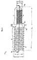
図1A〜図1Cは、本発明の一実施形態としての骨ねじ10を示している。図示のように、骨ねじ10は、少なくとも1条のねじ山13の形成された近位部分12、遠位部分14、およびねじ山付き近位部分12と遠位部分14との間に設けられた任意的に漸減直径の移行領域16を備えた軸部を有する。骨ねじ10の全体的な寸法は、使用意図に応じて様々であってよいが、好ましくは、骨ねじ10を椎骨の椎弓根中に植え込むことができる寸法である。骨ねじ10が脊柱での用途に用いられる例示の実施形態では、骨ねじ10は、約8mm〜100mmの長さlsを有する。1A to 1C show a bone screw 10 as an embodiment of the present invention. As shown, the bone screw 10 is provided between a
骨ねじ10の近位部分12は、種々の形態、形状および寸法のものであってよい。上述したように、近位部分12には好ましくは、少なくとも1条のねじ山13が形成されている。例示の実施形態では、ねじ山13は、近位端12aから、または近位端12aに隣接した地点から延び、移行領域16において、またはこれに隣接した地点で終端している。近位部分12の遠位端12bにおけるねじ山13の開始部は、近位部分12と骨との係合を容易にするよう、任意にセルフタッピング方式とすることができる。非限定的な例を挙げると、図1Cは、近位部分12の遠位端12bにあるねじ山13にセルフタッピング特徴3が形成された骨ねじ100を示している。 The
図1Bに戻ってこれを参照すると、近位部分12のねじ山13は、谷底13cと山の頂13dとの間に延びる、近位側へ向いたフランク13aおよび遠位側へ向いたフランク13bを有している。各フランク13a,13bは、寸法形状が様々であってよく、フランク13a,13bはそれぞれ、長手方向軸線Lに対し種々の角度αa,αbをなして延びるのがよい。非限定的な例を挙げると、フランク13a,13bは、図示のように互いに向かって収斂するのがよく、或いは、他の実施形態(図示せず)では、これらフランクは、互いに平行であってもよく、或いは種々の角度をなして互いに末広がりに広がっていてもよい。ねじ山13の山の頂13dもまた、種々の形状のものであってよく、例えば、鋭利なエッジを形成するよう尖っていてもよく、或いは、図示のように斜切されていてもよい。例示のねじ山形態は、角ねじ、のこ歯ねじ、海綿骨ねじ、皮質骨ねじ、またはこれらの幾つかの組合せを含む。Referring back to FIG. 1B, the
図1A〜図1Cに示す例示の実施形態では、ねじ山の寸法、形状およびピッチは、近位部分12の長さの少なくとも大部分に沿って一定のままである。しかしながら、他の実施形態では、ねじ山の寸法、形状およびピッチは、近位部分12の長さの少なくとも一部に沿って様々であってもよい。図1Aに示すように、近位部分12は、ねじ山13の谷底13cから測定した小さい方の直径(谷の径)D2およびねじ山13の山の頂13dから測定した大きい方の直径(外径)D1を有する。ねじ山13は、近位部分12の長さの大部分に沿って実質的に一定のままであるピッチP1を更に有し、したがって、ねじ山13は、各ねじ山形態相互間で軸線Lに沿って一様な間隔を有するようになっている。骨ねじ10が脊柱での用途に用いられる例示の実施形態では、近位部分12の小さい方の直径D2は、約2mm〜9mmであり、大きい方の直径D1は、約3mm〜12mmであり、ねじ山13のピッチP1は、約1〜12である。In the exemplary embodiment shown in FIGS. 1A-1C, the thread dimensions, shape, and pitch remain constant along at least most of the length of the
依然として図1A〜図1Cを参照すると、骨ねじ10の遠位部分14もまた、種々の形態のものであってよい。例示の実施形態では、遠位部分14にはねじ山15が形成され、このねじ山15は、谷底15cと山の頂15dとの間に延びる、近位側へ向いたフランク15aおよび遠位側へ向いたフランク15bを有している。遠位部分14に沿うねじ山15の形状、寸法およびピッチは、近位部分12に形成されたねじ山13に関して上述したように、様々であってよい。一実施形態では、遠位部分14は、ねじ山15の谷底15cから測定した小さい方の直径(谷の径)d2およびねじ山15の山の頂15dから測定した大きい方の直径(外径)d1を有している。遠位部分14の大きい方の直径d1は好ましくは、近位部分12の大きい方の直径D1よりも小さい。これは、遠位部分14が近位部分12よりも大きな骨トンネルを形成するのを阻止し、それにより、近位部分12が、既に遠位部分14を挿通した骨に係合することができるので、特に有利である。遠位部分14のねじ山15もまた、近位側ねじ山13のピッチP1よりも小さなピッチP2を有するのがよい。これにより、骨ねじの近位部分12は、遠位部分14よりも早く骨の中に進むことができ、それにより近位部分12と遠位部分14との間に伸長力を生じさせる。非限定的な例を挙げると、近位部分12のねじ山13は、遠位部分14のねじ山15のピッチP2の2倍であるピッチP1を有するのがよい。その結果、近位部分12は、遠位部分14の前進よりも2倍早く骨の中に前進することになる。骨ねじ10が脊柱での用途に用いられる例示の実施形態では、遠位部分14の小さい方の直径d2は、約1mm〜8mmであり、大きい方の直径d1は、約3mm〜10mmであり、ねじ山15のピッチP2は、約0〜10である。Still referring to FIGS. 1A-1C, the
図1A〜図1Cに示す例示の実施形態の近位部分12および遠位部分14は各々、1条のねじ山を有しているが、当業者であれば理解されるように、近位部分12および遠位部分14は、様々に変化する、または一様な寸法、形状およびピッチを有する任意の条数のねじ山を有することができる。 The
骨ねじ10の遠位部分14は、ねじ10の最も遠位側の端に形成された頂点14bを更に有する。頂点14bは、種々の形態のものであってよく、非限定的な例を挙げると、頂点14bは、円錐形またはねじ錐形の先端部の形態をしているのがよい。図1Aに示すように、ねじ10の頂点14bは、円錐形の形態をしており、ねじ山15は、遠位先端部14bの近くの位置で終端し、ねじ10のコアは、中実の円錐状構造体に形成されている。ねじ錐形先端部では、ねじ山は、ねじの遠位先端部のところまで延びてここで合体している。当業者であれば理解されるように、いずれの先端部を用いてもよく、或いは、変形例として頂点14bは、種々の他の形態のものであってもよい。頂点14bおよびねじ10の残部は、骨ねじをタップ立てすると共に/或いは、骨にあらかじめ穴をあける必要性をなくすために、セルフタッピングおよび/またはセルフドリリング骨ねじに形作られたものであってもよいが、このようにするかどうかは任意である。非限定的な例を挙げると、図1Cは、遠位部分14の遠位端14bの近くに位置するねじ山15に形成されたセルフタッピング特徴5および頂点14bに形成された別のセルフタッピング特徴7を示している。当業者であれば理解されるように、種々のセルフタッピングおよび/またはセルフドリリング特徴を用いることができる。 The
上述したように、骨ねじ10は、近位部分12と遠位部分14との間に延びる移行領域16を更に有することができる。移行領域16は好ましくは、ねじ10の近位部分12からねじ10の遠位部分14まで減少していく直径を持つ、軸部のねじ山が設けられていない(非螺設)領域である。図1Bに示すように、移行領域16は、遠位側直径dxよりも大きな近位側直径dyを有し、移行領域16の長さltに沿って近位側直径部と遠位側直径部との間に延びる移行領域16の表面は、好ましくは傾斜している。傾斜した移行領域16は、性能を向上させ、種々の直径およびピッチを有するねじを製造しやすくすることができる。傾斜した移行領域16が示されているが、移行領域16は、事実上任意の形態、形状および寸法を有することができ、例えば段付きの形態、または非テーパ形態のものであってよい。例示の実施形態(図示せず)では、移行領域16の長さltは、近位側ねじ山13がストリップではなく骨に確実に係合するよう、できるだけ小さい。As described above, the bone screw 10 can further include a transition region 16 that extends between the
骨ねじ10の植え込みを容易にするため、骨ねじ10を骨の中に押し込むねじ回し(図示せず)と嵌合するように、ねじ回し受入れ要素18(図1B)をねじ10の近位端12aに形成し、またはこれに取り付けるのがよい。ねじ回し受入れ要素18は、種々の形態のものであってよいが、例示の実施形態では、ねじ回し受入れ要素18は、近位部分12の最も近位側の端12aに形成された受口の形態をしている。受口18は、事実上任意の寸法形状のものであってよく、例えば、六角形のねじ回し部材を受け入れる六角形の受口とすることができる。変形例として、近位部分12には、ねじ回し工具に設けられた六角形の受口と嵌合する六角形のヘッドが形成されてもよい。当業者であれば理解されるように、種々のねじ回し受入れ要素を使用することができると共に/或いは骨ねじ10の近位端12aは、事実上任意の他の形態のものであってよい。他の実施形態では、骨ねじ10は、カニューレ挿入式のものであってもよく、例えば、骨ねじ10を貫通してガイドワイヤを受け入れるルーメンを有してもよいが、このようにするかどうかは任意である。 To facilitate implantation of the bone screw 10, the screwdriver receiving element 18 (FIG. 1B) is connected to the proximal end of the screw 10 so as to mate with a screwdriver (not shown) that pushes the bone screw 10 into the bone. It may be formed in or attached to 12a. Although the screwdriver receiving element 18 may take a variety of forms, in the illustrated embodiment, the screwdriver receiving element 18 is a receptacle formed at the most proximal end 12a of the
図2〜図5は、本発明の追加の実施形態としての骨ねじを示している。参照の目的で、同一の参照符号は、同一の部品を示すために用いられている。当業者であれば理解されるように、本発明の骨ねじは、本明細書において説明されると共に/或いは図示した特徴および当該技術分野において知られている他の特徴との任意の組合せを含むことが可能である。本発明の骨ねじは、図示の特定の実施形態には限定されない。 2-5 illustrate a bone screw as an additional embodiment of the present invention. For reference purposes, the same reference numerals are used to denote the same parts. As will be appreciated by those skilled in the art, the bone screw of the present invention includes any combination of the features described and / or illustrated herein and other features known in the art. It is possible. The bone screw of the present invention is not limited to the particular embodiment shown.
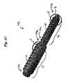
図2は、一実施形態としての骨ねじ100を示しており、この実施形態では、近位部分112に1条以上のねじ山が形成され、この近位部分が、伸延前および/または伸延中に骨ねじと骨との固定を達成するのを助けるために、漸変ねじ山形態を有している。特に、図示のように、骨ねじ100は、ピッチが互いに異なるねじ山113a,113bを備えた近位領域112aおよび遠位領域112bを含む近位部分112を有する。各領域112a,112bのねじ山113a,113bは、近位部分112の全長に沿って延びる1条のねじ山から形成することができ、或いは変形例として、近位部分112は、任意の条数のねじ山、例えば近位領域112aおよび遠位領域112bにそれぞれ形成された第1のねじ山および第2のねじ山を有してもよい。図2に示すように、近位部分112の遠位領域112bのねじ山113bは、ピッチが減少しており、したがって、近位部分112の近位領域112aのねじ山113aのピッチは、近位部分112の遠位領域112bのねじ山113bのピッチよりも大きくなっている。例示の実施形態では、遠位領域112bのねじ山113bのピッチは、以下に詳細に説明するように、ねじの遠位部分14に形成されたねじ山15のピッチに等しい。近位部分112の遠位領域112bのねじ山形態もまた様々であってよく、例示の実施形態では、ねじ山113bは、近位部分112に断続的に設けられており、これは、少なくとも部分的に棘付きであり、近位側へ向いたフランクが実質的に平らであって、遠位側へ向いたフランクが湾曲するようになっている。図2に示す実施形態の形態は、これにより、近位部分112bと遠位部分114bとの間に伸延力が形成される前に、近位部分112の遠位領域112bのねじ山113bを骨に係合させることができるので特に有利であり、これについても以下に詳細に説明する。さらに、ねじ山113bの棘付き形状は、骨内への挿入時に、骨ねじ100の戻りを阻止するのに役立つ。 FIG. 2 illustrates an
図3は、近位側から遠位側への方向に減少していく直径を有する遠位部分314を備えた骨ねじ300を示している。ねじ300の楔形遠位部分314には、いったん植え込まれると、骨に係合してねじ300の戻りを阻止する1つ以上の表面特徴部317が形成されるのがよいが、このようにするかどうかは任意である。この表面特徴部は、事実上任意の形態のものであってよいが、図3は、段付き形態の楔形遠位部分314を示しており、かかる段付き形態では、遠位部分314には、骨に係合するように構成された数個の環状隆起部317が形成されている。環状隆起部317は好ましくは、骨ねじ300の遠位端314bから近位端314aにかけて、周長が減少する。 FIG. 3 shows a bone screw 300 with a
植え込み時に拡張するように構成された遠位部分414を有する別の骨ねじ400が、図4に示されている。特に、骨ねじ400は、近位部分412を有し、この近位部分から延長部材416が遠位側に延びており、骨ねじ400は、延長部材416を受け入れるように構成された遠位部分414を有する。近位部分412の延長部材416は、事実上任意の形状、寸法および形態のものであってよいが、遠位部分414内に挿入されると、遠位部分414を拡張するようになっているべきである。遠位部分414は同様に、事実上任意の形状、寸法および形態のものであってよいが、延長部材416を受け入れると拡張して骨トンネルに係合するようになっているべきである。例示の実施形態では、遠位部分414は、その一部に沿って延びていて、遠位部分414を拡張させることができる少なくとも1つのスロット430を有する。別の実施形態では、延長部材416は、遠位部分414内に形成された、対応するねじ山と噛み合うよう、ねじ山(図示せず)が設けられたものであってよい。遠位部分414を別個の部品から形成することができるが、遠位部分414は、任意に、骨ねじ300の植え込みを容易にするよう、近位部分414に付一時的に取付け可能にしてもよい。。当業者であれば理解されるように、骨ねじは、種々の他の形態のものであってよい。 Another bone screw 400 having a
図5は、更に別の実施形態としての骨ねじ500を示しており、この骨ねじ500には、ピッチがねじ500の近位端500aから遠位端500bまで次第に減少していく1条のねじ山513が形成されている。ねじ軸部の実際の形状および寸法は、様々であってよいが、好ましくは、軸部の大きい方の直径と小さい方の直径が両方とも、近位端500aから遠位端500bまでテーパしている。使用にあたり、ねじ山513の漸減するピッチは、図1Aおよび図1Bを参照して説明した骨ねじ10と同一の効果をもたらすであろう。 FIG. 5 illustrates yet another embodiment of a
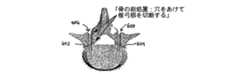
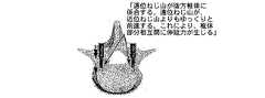
本発明の骨ねじは、骨の2つのセグメントを伸延するよう種々の医療手技で利用できるが、例示の実施形態では、骨ねじは、脊柱管を拡張するために用いられる。図6A〜図6Dは、使用中の骨ねじ10を示している。図6Aに示すように、椎骨600の椎弓根は、棘突起の両側が切断されていて、2つのギャップ602,604が形成されている。また、骨ねじ10を受け入れるために、2つのチャネル606,608を、横突起を貫通して椎弓根内へ、後方から前方の方向に穴あけすることもできるが、このようにするかどうかは任意である。各チャネル606,608は好ましくは、対応する骨ねじ10の近位部分12および遠位部分14を受け入れるために二重の直径を有している。具体的に説明すると、各チャネル606,608の後方部分は好ましくは、各チャネル606,608の前方部分よりも周長が長い。種々の寸法を有するドリルビットを用いて、二重直径のチャネルを形成することができる。 While the bone screw of the present invention can be used in various medical procedures to distract two segments of bone, in the illustrated embodiment, the bone screw is used to expand the spinal canal. 6A-6D show the bone screw 10 in use. As shown in FIG. 6A, the pedicle of the vertebra 600 is cut on both sides of the spinous process to form two gaps 602 and 604. It is also possible to pierce the two channels 606, 608 through the transverse process and into the pedicle in the posterior to anterior direction to receive the bone screw 10; Is optional. Each channel 606, 608 preferably has a double diameter for receiving the
図6Bに示すように、次に、骨ねじ10をねじ回し工具(図示せず)を用いて椎弓根のあらかじめ穴あけされたチャネル606,608の中に挿入する。ねじ10をチャネル606,608にねじ込むと、遠位部分14は、骨に係合しないで椎弓根の後方部分を通って前進する。ねじ10は、遠位部分14がチャネル606,608の後方部分を通り、近位側ねじ山13がまず最初にチャネル606,608の後方部分に係合するよう設計されている。遠位側ねじ山15が、チャネル606,608の前方部分に達すると、ねじ山15は、図6Cに示すように、骨の前方部分に係合し始める。遠位側ねじ山15は、近位側ねじ山13のピッチP1よりも小さなピッチP2を有しているので、遠位部分14は、ねじ10の近位部分12よりもゆっくりと前進する。これにより、椎骨の前方部分と後方部分との間に伸延力が与えられ、それにより、ねじ10を椎骨内にねじ込むと、椎骨の前方部分と後方部分が分離する。その結果、脊柱管は、図6Dに示すように拡張する。As shown in FIG. 6B, the bone screw 10 is then inserted into the pre-drilled channels 606, 608 of the pedicle using a screwdriver tool (not shown). When screw 10 is screwed into channels 606 and 608,
本発明の骨ねじ10は、種々の生物学的に適合性のある材料または例えば生分解性材料および/または非生分解性材料を含む材料の組合せから作られたものであってよい。適当な材料としては、例えば、骨伝導(osteoconductive)物質または死体の骨、例えば皮質骨が挙げられる。例示の実施形態では、近位部分12および遠位部分14に沿うねじ山13,15は、海綿骨で形成されるが、これらは、意図した使用領域に応じて皮質骨で作られたものであってもよい。他の適当な材料としては、例えば、ステンレス鋼、チタンのような金属や炭素繊維補強ポリマーまたはポリエチルエチルケトンが挙げられる。 The bone screw 10 of the present invention may be made from a variety of biologically compatible materials or combinations of materials including, for example, biodegradable materials and / or non-biodegradable materials. Suitable materials include, for example, osteoconductive materials or cadaver bone, such as cortical bone. In the illustrated embodiment, the
別の実施形態では、骨ねじ10または骨ねじ10の一部は、骨成長促進材料で被覆され、またはかかる材料から形成されたものであってよい。かかる材料の例としては、ヒドロキシアパタイト、燐酸カルシウムおよび他の材料、例えば生体活性ガラス、プラズマ、セラミック、多孔質材料、およびこれらの組合せが挙げられる。また、任意的にまたは変形例として、骨ねじ10または骨ねじ10の一部には、骨成長因子、例えば、幹細胞濃縮物および/または血小板の豊富な物質を注入してもよい。 In another embodiment, the bone screw 10 or a portion of the bone screw 10 may be coated with or formed from a bone growth promoting material. Examples of such materials include hydroxyapatite, calcium phosphate and other materials such as bioactive glass, plasma, ceramic, porous materials, and combinations thereof. Also, optionally or alternatively, bone screw 10 or a portion of bone screw 10 may be infused with a bone growth factor, such as a stem cell concentrate and / or a platelet rich substance.
当業者であれば理解されるように、本明細書において説明したインプラントは、脊柱手術用として説明したが、当該インプラントは、種々の医療手技での使用に適応可能である。したがって、本発明は、特許請求の範囲に示す内容を除き、具体的に図示すると共に説明した内容によっては限定されない。本明細書において引用した全ての刊行物および技術文献の記載内容全体を、参照によりここに引用する。 As will be appreciated by those skilled in the art, while the implants described herein have been described for spinal surgery, the implants are adaptable for use in a variety of medical procedures. Accordingly, the invention is not limited by what is specifically shown and described, except as indicated in the claims. The entire contents of all publications and technical literature cited herein are hereby incorporated by reference.
〔実施態様〕
(1)骨の2つのセグメントを伸延するための骨ねじにおいて、
ねじ山付き近位部分および遠位部分を備えた軸部を有し、前記遠位部分は、前記ねじ山付き近位部分の小さい方の直径よりも小さな大きい方の直径を有し、前記軸部の前記近位部分および前記遠位部分は、骨の2つのセグメント内に挿入されると、前記近位部分と前記遠位部分との間に伸延力を生じさせるよう構成されている、骨ねじ。
(2)実施態様1記載の骨ねじにおいて、
前記遠位部分には、ねじ山が形成されている、骨ねじ。
(3)実施態様1記載の骨ねじにおいて、
前記遠位部分の前記ねじ山のピッチは、前記ねじ山付き近位部分の前記ねじ山のピッチよりも小さい、骨ねじ。
(4)実施態様1記載の骨ねじにおいて、
前記骨ねじは、セルフタッピングおよび/またはセルフドリリング型である、骨ねじ。
(5)実施態様1記載の骨ねじにおいて、
前記ねじ山付き近位部分の前記ねじ山のピッチは、前記近位部分の長さに沿って変化している、骨ねじ。Embodiment
(1) In a bone screw for distracting two segments of bone,
A shaft with a threaded proximal portion and a distal portion, the distal portion having a larger diameter that is smaller than the smaller diameter of the threaded proximal portion; The proximal portion and the distal portion of a section configured to create a distraction force between the proximal portion and the distal portion when inserted into two segments of bone; screw.
(2) In the bone screw according to embodiment 1,
A bone screw, wherein the distal portion is threaded.
(3) In the bone screw according to embodiment 1,
The bone screw, wherein the thread pitch of the distal portion is less than the thread pitch of the threaded proximal portion.
(4) In the bone screw according to embodiment 1,
The bone screw is self-tapping and / or self-drilling.
(5) In the bone screw according to embodiment 1,
A bone screw, wherein a pitch of the thread of the threaded proximal portion varies along a length of the proximal portion.
(6)実施態様1記載の骨ねじにおいて、
前記軸部の前記近位部分と前記遠位部分は、互いに取り外し可能に結合し、前記近位部分は、前記遠位部分の少なくとも一部が前記近位部分との係合の際に拡張するよう前記遠位部分に結合するようになっている、骨ねじ。
(7)実施態様1記載の骨ねじにおいて、前記遠位部分の大きい方の直径は、近位側から遠位側の方向に減少している、骨ねじ。
(8)実施態様1記載の骨ねじにおいて、
前記遠位部分は、段付き直径を有し、前記段付き直径は、近位側から遠位側の方向に小刻みに減少するようになっている、骨ねじ。
(9)実施態様1記載の骨ねじにおいて、
前記遠位部分から少なくとも1つの棘が突き出ており、該棘は、骨に係合するようになっている、骨ねじ。
(10)実施態様1記載の骨ねじにおいて、
前記ねじ山付き近位部分と前記遠位部分との間に設けられた漸減直径の移行領域を更に有する、骨ねじ。(6) In the bone screw according to embodiment 1,
The proximal portion and the distal portion of the shaft portion are detachably coupled to each other and the proximal portion expands upon engagement of at least a portion of the distal portion with the proximal portion. A bone screw adapted to be coupled to the distal portion.
(7) The bone screw of embodiment 1, wherein the larger diameter of the distal portion decreases in the direction from the proximal side to the distal side.
(8) In the bone screw according to embodiment 1,
The bone screw, wherein the distal portion has a stepped diameter, the stepped diameter being adapted to gradually decrease from a proximal side to a distal side.
(9) In the bone screw according to embodiment 1,
A bone screw, wherein at least one barb protrudes from the distal portion, the barb adapted to engage bone.
(10) In the bone screw according to embodiment 1,
The bone screw further comprising a transitional area of decreasing diameter provided between the threaded proximal portion and the distal portion.
(11)実施態様10記載の骨ねじにおいて、
前記移行領域にはねじ山が設けられていない、骨ねじ。
(12)実施態様10記載の骨ねじにおいて、
前記移行領域はテーパしている、骨ねじ。
(13)実施態様1記載の骨ねじにおいて、
前記軸部は、カニューレ挿入式である、骨ねじ。
(14)実施態様1記載の骨ねじにおいて、
前記ねじの少なくとも一部は、骨成長促進材料で被覆されている、骨ねじ。
(15)実施態様14記載の骨ねじにおいて、
前記骨成長促進材料は、ヒドロキシアパタイト、燐酸カルシウム、生体活性ガラス、プラスマ、セラミックス、多孔質材料、およびこれらの組合せから成る群から選択される、骨ねじ。(11) In the bone screw according to embodiment 10,
Bone screw, wherein the transition region is not threaded.
(12) In the bone screw according to embodiment 10,
The transition region is tapered, bone screw.
(13) In the bone screw according to embodiment 1,
The shank is a cannulated bone screw.
(14) In the bone screw according to embodiment 1,
A bone screw, wherein at least a portion of the screw is coated with a bone growth promoting material.
(15) In the bone screw according to
The bone growth promoting material is a bone screw selected from the group consisting of hydroxyapatite, calcium phosphate, bioactive glass, plasma, ceramics, porous materials, and combinations thereof.
(16)実施態様1記載の骨ねじにおいて、
前記ねじの少なくとも一部は、皮質骨グラフトで作られている、骨ねじ。
(17)実施態様1記載の骨ねじにおいて、
前記骨ねじの近位端に設けられたねじ回し受入れ要素を更に有する、骨ねじ。
(18)実施態様17記載の骨ねじにおいて、
前記ねじ回し受入れ要素は、前記軸部の前記近位部分の最も近位側の端に形成された六角形の受口を含む、骨ねじ。
(19)実施態様17記載の骨ねじにおいて、
前記ねじ回し受入れ要素は、前記軸部の前記近位部分の最も近位側の端に形成された六角形のヘッドを含む、骨ねじ。
(20)骨ねじにおいて、
ねじ山付き近位部分およびねじ山付き遠位部分を備えた軸部を有し、前記ねじ山付き遠位部分は、ピッチが前記ねじ山付き近位部分のねじ山のピッチよりも小さな少なくとも1条のねじ山を有し、前記遠位部分の少なくとも一部の大きい方の直径は、前記ねじ山付き近位部分の小さい方の直径よりも小さい、骨ねじ。(16) In the bone screw according to embodiment 1,
A bone screw, wherein at least a portion of the screw is made of a cortical bone graft.
(17) In the bone screw according to embodiment 1,
The bone screw further comprising a screwdriver receiving element provided at a proximal end of the bone screw.
(18) In the bone screw according to embodiment 17,
The screwdriver receiving element includes a hexagonal receptacle formed at a proximal end of the proximal portion of the shank.
(19) In the bone screw according to embodiment 17,
The screw driver receiving element includes a hexagonal head formed at a most proximal end of the proximal portion of the shank.
(20) In the bone screw,
A shank having a threaded proximal portion and a threaded distal portion, the threaded distal portion having at least one pitch less than the thread pitch of the threaded proximal portion; A bone screw having a thread of threads, wherein the larger diameter of at least a portion of the distal portion is smaller than the smaller diameter of the threaded proximal portion.
(21) 骨ねじにおいて、
軸部を有し、
該軸部は、
少なくとも1条のねじ山が形成された近位部分であって、該少なくとも1条のねじ山は、前記近位部分の近位領域に第1のピッチおよび前記近位部分の遠位領域に第2のピッチを有する、近位部分と、
少なくとも1条のねじ山が形成された遠位部分であって、該少なくとも1条のねじ山は、第3のピッチを有する、遠位部分と、
を有し、
前記第2のピッチは、前記第3のピッチに寸法がほぼ等しく、前記第1のピッチとは寸法が異なる、骨ねじ。
(22)実施態様21記載の骨ねじにおいて、
前記第3のピッチは、前記第1のピッチよりも小さい、骨ねじ。
(23)実施態様21記載の骨ねじにおいて、
前記第2のピッチは、前記第3のピッチよりも大きいかまたはこれに等しくかつ前記第1のピッチよりも小さい、骨ねじ。
(24)実施態様21記載の骨ねじにおいて、
前記近位部分の前記遠位領域の前記少なくとも1条のねじ山は、前記骨ねじを骨内に植え込んだときに、前記骨ねじの戻りを阻止するよう形作られている、骨ねじ。
(25)実施態様21記載の骨ねじにおいて、
前記近位部分の前記少なくとも1条のねじ山は、前記近位部分の前記近位領域と前記遠位領域との間に延びる単一のねじ山を含む、骨ねじ。(21) In bone screws,
Having a shaft,
The shaft is
A proximal portion formed with at least one thread, the at least one thread having a first pitch in a proximal region of the proximal portion and a first region in a distal region of the proximal portion; A proximal portion having a pitch of two;
A distal portion formed with at least one thread, the at least one thread having a third pitch;
Have
The bone pitch, wherein the second pitch is substantially equal in size to the third pitch and is different in size from the first pitch.
(22) In the bone screw according to embodiment 21,
The third pitch is a bone screw smaller than the first pitch.
(23) In the bone screw according to embodiment 21,
The bone screw, wherein the second pitch is greater than or equal to the third pitch and smaller than the first pitch.
(24) In the bone screw according to embodiment 21,
The bone screw, wherein the at least one thread in the distal region of the proximal portion is shaped to prevent return of the bone screw when the bone screw is implanted in bone.
(25) In the bone screw according to embodiment 21,
The bone screw, wherein the at least one thread of the proximal portion includes a single thread extending between the proximal and distal regions of the proximal portion.
(26)実施態様21記載の骨ねじにおいて、
前記近位部分の前記少なくとも1条のねじ山は、前記近位部分の前記近位領域に形成された第1のねじ山および前記近位部分の前記遠位領域に形成された第2のねじ山を含む、骨ねじ。
(27)骨の2つのセグメントを伸延するための骨ねじにおいて、
ねじ山が形成されていて、近位端と遠位端との間に延びる軸部であって、前記ねじ山は、前記軸部の長さに沿って近位側から遠位側の方向に次第に減少したピッチを有する、軸部と、
前記軸部の近位端に形成されまたは該近位端に結合されたねじ回し受入れ要素と、
を有する、骨ねじ。
(28)脊柱管を拡張する方法において、
近位部分および遠位部分を含む軸部を有する骨ねじを提供する段階であって、前記近位部分および遠位部分は、骨の2つのセグメント内に挿入されると、前記近位部分と前記遠位部分との間に伸延力を生じさせるよう構成されている、段階と、
棘突起に隣接して椎体の椎弓根に穴を形成する段階と、
前記穴を横切ってかつ前記椎体に隣接して前記椎弓根を切断して2つの骨部分を形成する段階と、 前記骨ねじを前記穴の中へ前進させる段階であって、前記骨ねじの前記近位部分および前記遠位部分が、前記2つの骨部分の相互間の距離を広げる、段階と、
を有する、方法。
(29)実施態様28記載の方法において、
前記近位部分および前記遠位部分のうち少なくとも一方には、ねじ山が形成されている、方法。
(30)実施態様28記載の方法において、
前記近位部分および前記遠位部分の各々には、ねじ山が形成され、前記遠位部分の前記ねじ山のピッチは、前記近位部分の前記ねじ山のピッチよりも小さい、方法。(26) In the bone screw according to embodiment 21,
The at least one thread of the proximal portion includes a first thread formed in the proximal region of the proximal portion and a second screw formed in the distal region of the proximal portion. Bone screws, including mountains.
(27) In a bone screw for distracting two segments of bone,
A shaft formed with a thread and extending between a proximal end and a distal end, the thread being in a proximal-to-distal direction along the length of the shaft A shank having a progressively reduced pitch;
A screwdriver receiving element formed at or coupled to the proximal end of the shank;
Having a bone screw.
(28) In a method for dilating a spinal canal,
Providing a bone screw having a shank including a proximal portion and a distal portion, the proximal portion and the distal portion being inserted into two segments of bone and Configured to create a distraction force with the distal portion;
Forming a hole in the pedicle of the vertebral body adjacent to the spinous process;
Cutting the pedicles across the hole and adjacent to the vertebral body to form two bone portions; and advancing the bone screw into the hole, the bone screw The proximal portion and the distal portion of the second portion increase the distance between the two bone portions;
Having a method.
(29) In the method of embodiment 28,
A method wherein at least one of the proximal portion and the distal portion is threaded.
(30) In the method of embodiment 28,
Each of the proximal and distal portions is threaded, and the pitch of the threads of the distal portion is less than the pitch of the threads of the proximal portion.
(31)実施態様28記載の方法において、
前記近位部分には、前記近位部分の長さに沿って変化するピッチを有するねじ山が形成されている、方法。
(32)実施態様28記載の方法において、
前記骨ねじの少なくとも一部は、骨成長促進材料で被覆されまたは該骨成長促進材料で作られている、方法。
(33)実施態様28記載の方法において、
前記骨ねじは、前記軸部の前記近位部分の近位端に設けられたねじ回し受入れ要素を更に有する、方法。(31) In the method of embodiment 28,
The method wherein the proximal portion is threaded with a pitch that varies along the length of the proximal portion.
(32) In the method of embodiment 28,
The method wherein at least a portion of the bone screw is coated with or made of a bone growth promoting material.
(33) In the method of embodiment 28,
The bone screw further comprises a screwdriver receiving element provided at a proximal end of the proximal portion of the shank.
Claims (28)
Translated fromJapaneseねじ山付き近位部分および遠位部分を備えた軸部を有し、
前記遠位部分は、前記ねじ山付き近位部分の小さい方の直径よりも小さな大きい方の直径を有し、
前記軸部の前記近位部分および前記遠位部分は、骨の2つのセグメント内に挿入されると、前記近位部分と前記遠位部分との間に伸延力を生じさせるよう構成されている、
骨ねじ。In a bone screw for distracting two segments of bone,
Having a shank with a threaded proximal portion and a distal portion;
The distal portion has a larger diameter smaller than the smaller diameter of the threaded proximal portion;
The proximal portion and the distal portion of the shaft are configured to create a distraction force between the proximal portion and the distal portion when inserted into two segments of bone. ,
Bone screw.
前記遠位部分には、ねじ山が形成されている、骨ねじ。The bone screw of claim 1,
A bone screw, wherein the distal portion is threaded.
前記遠位部分の前記ねじ山のピッチは、前記ねじ山付き近位部分の前記ねじ山のピッチよりも小さい、骨ねじ。The bone screw of claim 1,
The bone screw, wherein the thread pitch of the distal portion is less than the thread pitch of the threaded proximal portion.
前記骨ねじは、セルフタッピングおよび/またはセルフドリリング型である、骨ねじ。The bone screw of claim 1,
The bone screw is self-tapping and / or self-drilling.
前記ねじ山付き近位部分の前記ねじ山のピッチは、前記近位部分の長さに沿って変化している、骨ねじ。The bone screw of claim 1,
A bone screw, wherein a pitch of the thread of the threaded proximal portion varies along a length of the proximal portion.
前記軸部の前記近位部分と前記遠位部分は、互いに取り外し可能に結合し、前記近位部分は、前記遠位部分の少なくとも一部が前記近位部分との係合の際に拡張するよう前記遠位部分に結合するようになっている、骨ねじ。The bone screw of claim 1,
The proximal portion and the distal portion of the shaft portion are detachably coupled to each other and the proximal portion expands upon engagement of at least a portion of the distal portion with the proximal portion. A bone screw adapted to be coupled to the distal portion.
前記遠位部分の大きい方の直径は、近位側から遠位側の方向に減少している、骨ねじ。The bone screw of claim 1,
The bone screw, wherein the larger diameter of the distal portion decreases in the proximal to distal direction.
前記遠位部分は、段付き直径を有し、前記段付き直径は、近位側から遠位側の方向に小刻みに減少するようになっている、骨ねじ。The bone screw of claim 1,
The bone screw, wherein the distal portion has a stepped diameter, the stepped diameter being adapted to gradually decrease from a proximal side to a distal side.
前記遠位部分から少なくとも1つの棘が突き出ており、該棘は、骨に係合するようになっている、骨ねじ。The bone screw of claim 1,
A bone screw, wherein at least one barb protrudes from the distal portion, the barb adapted to engage bone.
前記ねじ山付き近位部分と前記遠位部分との間に設けられた漸減直径の移行領域を更に有する、骨ねじ。The bone screw of claim 1,
The bone screw further comprising a transitional area of decreasing diameter provided between the threaded proximal portion and the distal portion.
前記移行領域にはねじ山が設けられていない、骨ねじ。The bone screw of claim 10,
Bone screw, wherein the transition region is not threaded.
前記移行領域はテーパしている、骨ねじ。The bone screw of claim 10,
The transition region is tapered, bone screw.
前記軸部は、カニューレ挿入式である、骨ねじ。The bone screw of claim 1,
The shank is a cannulated bone screw.
前記ねじの少なくとも一部は、骨成長促進材料で被覆されている、骨ねじ。The bone screw of claim 1,
A bone screw, wherein at least a portion of the screw is coated with a bone growth promoting material.
前記骨成長促進材料は、ヒドロキシアパタイト、燐酸カルシウム、生体活性ガラス、プラスマ、セラミックス、多孔質材料、およびこれらの組合せから成る群から選択される、骨ねじ。The bone screw of claim 14,
The bone growth promoting material is a bone screw selected from the group consisting of hydroxyapatite, calcium phosphate, bioactive glass, plasma, ceramics, porous materials, and combinations thereof.
前記ねじの少なくとも一部は、皮質骨グラフトで作られている、骨ねじ。The bone screw of claim 1,
A bone screw, wherein at least a portion of the screw is made of a cortical bone graft.
前記骨ねじの近位端に設けられたねじ回し受入れ要素を更に有する、骨ねじ。The bone screw of claim 1,
The bone screw further comprising a screwdriver receiving element provided at a proximal end of the bone screw.
前記ねじ回し受入れ要素は、前記軸部の前記近位部分の最も近位側の端に形成された六角形の受口を含む、骨ねじ。The bone screw of claim 17,
The screwdriver receiving element includes a hexagonal receptacle formed at a proximal end of the proximal portion of the shank.
前記ねじ回し受入れ要素は、前記軸部の前記近位部分の最も近位側の端に形成された六角形のヘッドを含む、骨ねじ。The bone screw of claim 17,
The screw driver receiving element includes a hexagonal head formed at a most proximal end of the proximal portion of the shank.
ねじ山付き近位部分およびねじ山付き遠位部分を備えた軸部を有し、前記ねじ山付き遠位部分は、ピッチが前記ねじ山付き近位部分のねじ山のピッチよりも小さな少なくとも1条のねじ山を有し、前記遠位部分の少なくとも一部の大きい方の直径は、前記ねじ山付き近位部分の小さい方の直径よりも小さい、骨ねじ。In bone screw,
A shank having a threaded proximal portion and a threaded distal portion, the threaded distal portion having at least one pitch less than the thread pitch of the threaded proximal portion; A bone screw having a thread of threads, wherein the larger diameter of at least a portion of the distal portion is smaller than the smaller diameter of the threaded proximal portion.
軸部を有し、
該軸部は、
少なくとも1条のねじ山が形成された近位部分であって、該少なくとも1条のねじ山は、前記近位部分の近位領域に第1のピッチおよび前記近位部分の遠位領域に第2のピッチを有する、近位部分と、
少なくとも1条のねじ山が形成された遠位部分であって、該少なくとも1条のねじ山は、第3のピッチを有する、遠位部分と、
を有し、
前記第2のピッチは、前記第3のピッチに寸法がほぼ等しく、前記第1のピッチとは寸法が異なる、骨ねじ。In bone screw,
Having a shaft,
The shaft is
A proximal portion formed with at least one thread, the at least one thread having a first pitch in a proximal region of the proximal portion and a first region in a distal region of the proximal portion; A proximal portion having a pitch of two;
A distal portion formed with at least one thread, the at least one thread having a third pitch;
Have
The bone pitch, wherein the second pitch is substantially equal in size to the third pitch and is different in size from the first pitch.
前記第3のピッチは、前記第1のピッチよりも小さい、骨ねじ。The bone screw of claim 21,
The third pitch is a bone screw smaller than the first pitch.
前記第2のピッチは、前記第3のピッチよりも大きいかまたはこれに等しくかつ前記第1のピッチよりも小さい、骨ねじ。The bone screw of claim 21,
The bone screw, wherein the second pitch is greater than or equal to the third pitch and smaller than the first pitch.
前記近位部分の前記遠位領域の前記少なくとも1条のねじ山は、前記骨ねじを骨内に植え込んだときに、前記骨ねじの戻りを阻止するよう形作られている、骨ねじ。The bone screw of claim 21,
The bone screw, wherein the at least one thread in the distal region of the proximal portion is shaped to prevent return of the bone screw when the bone screw is implanted in bone.
前記近位部分の前記少なくとも1条のねじ山は、前記近位部分の前記近位領域と前記遠位領域との間に延びる単一のねじ山を含む、骨ねじ。The bone screw of claim 21,
The bone screw, wherein the at least one thread of the proximal portion includes a single thread extending between the proximal and distal regions of the proximal portion.
前記近位部分の前記少なくとも1条のねじ山は、前記近位部分の前記近位領域に形成された第1のねじ山および前記近位部分の前記遠位領域に形成された第2のねじ山を含む、骨ねじ。The bone screw of claim 21,
The at least one thread of the proximal portion includes a first thread formed in the proximal region of the proximal portion and a second screw formed in the distal region of the proximal portion. Bone screws, including mountains.
ねじ山が形成されていて、近位端と遠位端との間に延びる軸部であって、前記ねじ山は、前記軸部の長さに沿って近位側から遠位側の方向に次第に減少したピッチを有する、軸部と、
前記軸部の近位端に形成されまたは該近位端に結合されたねじ回し受入れ要素と、
を有する、骨ねじ。In a bone screw for distracting two segments of bone,
A shaft formed with a thread and extending between a proximal end and a distal end, the thread being in a proximal-to-distal direction along the length of the shaft A shank having a progressively reduced pitch;
A screwdriver receiving element formed at or coupled to the proximal end of the shank;
Having a bone screw.
近位部分および遠位部分を含む軸部を有する骨ねじを提供する段階であって、前記近位部分および遠位部分は、骨の2つのセグメント内に挿入されると、前記近位部分と前記遠位部分との間に伸延力を生じさせるよう構成されている、段階と、
棘突起に隣接して椎体の椎弓根に穴を形成する段階と、
前記穴を横切ってかつ前記椎体に隣接して前記椎弓根を切断して2つの骨部分を形成する段階と、 前記骨ねじを前記穴の中へ前進させる段階であって、前記骨ねじの前記近位部分および前記遠位部分が、前記2つの骨部分の相互間の距離を広げる、段階と、
を有する、方法。In a method for dilating the spinal canal,
Providing a bone screw having a shank including a proximal portion and a distal portion, the proximal portion and the distal portion being inserted into two segments of bone and Configured to create a distraction force with the distal portion;
Forming a hole in the pedicle of the vertebral body adjacent to the spinous process;
Cutting the pedicles across the hole and adjacent to the vertebral body to form two bone portions; and advancing the bone screw into the hole, the bone screw The proximal portion and the distal portion of the second portion increase the distance between the two bone portions;
Having a method.
Applications Claiming Priority (2)
| Application Number | Priority Date | Filing Date | Title |
|---|---|---|---|
| US10/638,821US7708766B2 (en) | 2003-08-11 | 2003-08-11 | Distraction screw |
| PCT/US2004/024123WO2005018684A2 (en) | 2003-08-11 | 2004-07-27 | Distraction screw |
Publications (1)
| Publication Number | Publication Date |
|---|---|
| JP2007502152Atrue JP2007502152A (en) | 2007-02-08 |
Family
ID=34135741
Family Applications (1)
| Application Number | Title | Priority Date | Filing Date |
|---|---|---|---|
| JP2006523211APendingJP2007502152A (en) | 2003-08-11 | 2004-07-27 | Distraction screw |
Country Status (6)
| Country | Link |
|---|---|
| US (1) | US7708766B2 (en) |
| EP (1) | EP1653871A4 (en) |
| JP (1) | JP2007502152A (en) |
| AU (1) | AU2004266568B2 (en) |
| CA (1) | CA2535342C (en) |
| WO (1) | WO2005018684A2 (en) |
Cited By (8)
| Publication number | Priority date | Publication date | Assignee | Title |
|---|---|---|---|---|
| US9044277B2 (en) | 2010-07-12 | 2015-06-02 | DePuy Synthes Products, Inc. | Pedicular facet fusion screw with plate |
| JP2015531282A (en)* | 2012-10-03 | 2015-11-02 | ゲイリー ジャック リードGary Jack REED | Medical fastener |
| KR101834175B1 (en)* | 2010-09-30 | 2018-03-05 | 바이오테크놀로지 인스티튜트, 아이 엠에이에스 디, 에스. 엘. | Implant-expander for expanding the jawbone crest |
| US10085782B2 (en) | 2013-03-06 | 2018-10-02 | Rtg Scientific, Llc | Bone screw |
| JP2019534122A (en)* | 2016-11-07 | 2019-11-28 | アキュイティブ テクノロジーズ,インコーポレイティッド | Reinforced, in-situ curable biodegradable anchor |
| JP2021514811A (en)* | 2018-02-27 | 2021-06-17 | アキュームド・エルエルシー | Bone fasteners with partially overlapping threads and changing leads |
| JP2022167120A (en)* | 2021-04-22 | 2022-11-04 | 秀富 寺井 | medical bolt |
| JP2023517596A (en)* | 2020-03-11 | 2023-04-26 | デピュイ・シンセス・プロダクツ・インコーポレイテッド | Compression nut and system for treating bone |
Families Citing this family (80)
| Publication number | Priority date | Publication date | Assignee | Title |
|---|---|---|---|---|
| US7641657B2 (en)* | 2003-06-10 | 2010-01-05 | Trans1, Inc. | Method and apparatus for providing posterior or anterior trans-sacral access to spinal vertebrae |
| US7014633B2 (en) | 2000-02-16 | 2006-03-21 | Trans1, Inc. | Methods of performing procedures in the spine |
| US6558390B2 (en) | 2000-02-16 | 2003-05-06 | Axiamed, Inc. | Methods and apparatus for performing therapeutic procedures in the spine |
| US7744599B2 (en)* | 2000-02-16 | 2010-06-29 | Trans1 Inc. | Articulating spinal implant |
| DK1578315T3 (en)* | 2000-02-16 | 2008-10-06 | Trans1 Inc | Device for vertebral column distribution and fusion |
| US6558386B1 (en)* | 2000-02-16 | 2003-05-06 | Trans1 Inc. | Axial spinal implant and method and apparatus for implanting an axial spinal implant within the vertebrae of the spine |
| US20030191474A1 (en)* | 2000-02-16 | 2003-10-09 | Cragg Andrew H. | Apparatus for performing a discectomy through a trans-sacral axial bore within the vertebrae of the spine |
| US6740090B1 (en)* | 2000-02-16 | 2004-05-25 | Trans1 Inc. | Methods and apparatus for forming shaped axial bores through spinal vertebrae |
| US20050101961A1 (en)* | 2003-11-12 | 2005-05-12 | Huebner Randall J. | Bone screws |
| GB0320375D0 (en)* | 2003-08-30 | 2003-10-01 | Grampian Univ Hospitals | Apparatus and method |
| AU2004283727A1 (en)* | 2003-10-23 | 2005-05-06 | Trans1 Inc. | Tools and tool kits for performing minimally invasive procedures on the spine |
| US20060149265A1 (en)* | 2004-09-07 | 2006-07-06 | Anthony James | Minimal thickness bone plate locking mechanism |
| US9463012B2 (en) | 2004-10-26 | 2016-10-11 | P Tech, Llc | Apparatus for guiding and positioning an implant |
| FR2881942B1 (en)* | 2005-02-14 | 2007-04-06 | Fixano Soc Par Actions Simplif | OSTEOSYNTHESIS EQUIPMENT |
| US8057521B2 (en)* | 2005-06-03 | 2011-11-15 | Southern Spine, Llc | Surgical stabilization system |
| WO2007021772A2 (en)* | 2005-08-09 | 2007-02-22 | Trans1, Inc. | Exchange system for axial spinal procedures |
| ATE523155T1 (en)* | 2005-10-28 | 2011-09-15 | Medartis Ag | THREAD FORMING SCREW |
| WO2007086622A1 (en)* | 2006-01-27 | 2007-08-02 | Osstem Implant Co., Ltd | Fixture |
| US9849216B2 (en) | 2006-03-03 | 2017-12-26 | Smith & Nephew, Inc. | Systems and methods for delivering a medicament |
| US20070213731A1 (en)* | 2006-03-07 | 2007-09-13 | Prusmack Chad J | Pedicle Screws for Osteoporosis |
| US8147531B2 (en)* | 2006-03-17 | 2012-04-03 | Tornier, Inc. | Compression pin with opposed threaded regions |
| US8361129B2 (en)* | 2006-04-28 | 2013-01-29 | Depuy Spine, Inc. | Large diameter bone anchor assembly |
| US20070288024A1 (en)* | 2006-06-06 | 2007-12-13 | Sohrab Gollogly | Bone fixation |
| US20080177333A1 (en)* | 2006-10-24 | 2008-07-24 | Warsaw Orthopedic, Inc. | Adjustable jacking implant |
| US8414628B2 (en)* | 2006-10-26 | 2013-04-09 | Warsaw Orthopedic, Inc. | Bone screw |
| US20090198291A1 (en)* | 2006-10-26 | 2009-08-06 | Warsaw Orthopedic, Inc. | Bone screw |
| US7931651B2 (en)* | 2006-11-17 | 2011-04-26 | Wake Lake University Health Sciences | External fixation assembly and method of use |
| US9827023B2 (en) | 2007-01-29 | 2017-11-28 | Life Spine, Inc. | Craniospinal fusion method and apparatus |
| US8182511B2 (en)* | 2007-01-29 | 2012-05-22 | Polaris Biotechnology, Inc. | Craniospinal fusion method and apparatus |
| US8083743B2 (en) | 2007-01-29 | 2011-12-27 | Polaris Biotechnology, Inc. | Craniospinal fusion method and apparatus |
| US20090036894A1 (en)* | 2007-01-29 | 2009-02-05 | Polaris Biotechnology, Inc. | Method of treating a neurological condition through correction and stabilization of the clivo-axial angle |
| US8403965B2 (en)* | 2007-01-29 | 2013-03-26 | Polaris Biotechnology, Inc. | Vertebra attachment method and system |
| US8556939B2 (en)* | 2008-01-08 | 2013-10-15 | Fraser Cummins Henderson | Mathematical relationship of strain, neurological dysfunction and abnormal behavior resulting from neurological dysfunction of the brainstem |
| WO2008112831A1 (en)* | 2007-03-12 | 2008-09-18 | Arya Nick Shamie | Improved cervical support system |
| FR2916624B1 (en)* | 2007-05-29 | 2009-08-21 | Small Bone Innovations Interna | BONE SCREW, IN PARTICULAR OSTEOSYNTHESIS |
| US8668725B2 (en)* | 2007-07-13 | 2014-03-11 | Southern Spine, Llc | Bone screw |
| US20090043311A1 (en)* | 2007-08-07 | 2009-02-12 | Koros Tibor B | Offset distraction device and method of use |
| WO2009089395A2 (en)* | 2008-01-08 | 2009-07-16 | Polaris Biotechnology, Inc. | Osteointegration apparatus |
| CA2717610A1 (en)* | 2008-03-06 | 2009-09-11 | Synthes Usa, Llc | Facet interference screw |
| US11224521B2 (en) | 2008-06-06 | 2022-01-18 | Providence Medical Technology, Inc. | Cervical distraction/implant delivery device |
| CA2725811A1 (en)* | 2008-06-06 | 2009-12-10 | Providence Medical Technology, Inc. | Facet joint implants and delivery tools |
| WO2010017168A2 (en)* | 2008-08-05 | 2010-02-11 | University Of Toledo | Pedicle screw assembly having a retractable screw tip for facilitating the securement of the pedicle screw assembly to a spinal vertebra |
| US8403973B2 (en)* | 2008-08-05 | 2013-03-26 | The University Of Toledo | Pedicle screw assembly having a retractable screw tip for facilitating the securement of the pedicle screw assembly to a spinal vertebra |
| KR100890034B1 (en)* | 2008-10-09 | 2009-03-25 | (주)코리아 본 뱅크 | Spinal Screw |
| BRPI0920250A2 (en) | 2008-10-15 | 2016-11-22 | Smith & Nephew Inc | composite internal fasteners |
| EP2745789B1 (en) | 2008-10-30 | 2017-04-19 | Depuy Spine Inc. | Systems for delivering bone cement to a bone anchor |
| US9011504B2 (en)* | 2009-10-02 | 2015-04-21 | Gary Reed | Apparatus and method for use in the treatment of hammertoe |
| US8361123B2 (en) | 2009-10-16 | 2013-01-29 | Depuy Spine, Inc. | Bone anchor assemblies and methods of manufacturing and use thereof |
| US20110112373A1 (en)* | 2009-11-10 | 2011-05-12 | Trans1 Inc. | Soft tissue access apparatus and methods for spinal surgery |
| FR2957239B1 (en)* | 2010-03-09 | 2013-06-28 | Synchro Medical | SCREWS FOR BONE REPAIR |
| US8986355B2 (en) | 2010-07-09 | 2015-03-24 | DePuy Synthes Products, LLC | Facet fusion implant |
| US20120065692A1 (en)* | 2010-09-10 | 2012-03-15 | Lloyd Champagne | Proximal interphalangeal fusion device |
| US9606011B2 (en)* | 2010-09-21 | 2017-03-28 | Mayo Foundation For Medical Education And Research | Methods and materials for calibrating a caloric test |
| US20120116458A1 (en)* | 2010-11-08 | 2012-05-10 | Warsaw Orthopedic, Inc. | Modular pivotable screw assembly and method |
| US9155580B2 (en)* | 2011-08-25 | 2015-10-13 | Medos International Sarl | Multi-threaded cannulated bone anchors |
| WO2013052626A1 (en) | 2011-10-05 | 2013-04-11 | The Unversity Of Akron | Reduced shock breakaway set screw for use with a surgical construct |
| ES2676696T3 (en)* | 2011-10-21 | 2018-07-24 | Innovative Surgical Designs Inc. | Surgical implants for percutaneous lengthening of the spinal pedicles to correct spinal stenosis |
| WO2013082576A1 (en)* | 2011-12-01 | 2013-06-06 | Eminent Spine Llc | Bone screw |
| US20140277190A1 (en)* | 2013-03-14 | 2014-09-18 | Howmedica Osteonics Corp. | Compression screw with variable pitch thread |
| WO2014159225A2 (en) | 2013-03-14 | 2014-10-02 | Baxano Surgical, Inc. | Spinal implants and implantation system |
| US9968460B2 (en) | 2013-03-15 | 2018-05-15 | Medsmart Innovation Inc. | Dynamic spinal segment replacement |
| CN105916458B (en)* | 2013-06-24 | 2019-09-27 | 托莱多大学 | Bioactive Fusion Devices |
| DE102013106758B4 (en)* | 2013-06-27 | 2022-06-09 | Aesculap Aktiengesellschaft | Out-of-round pedicle screw |
| US10531900B2 (en)* | 2014-04-17 | 2020-01-14 | Zimmer Biomet CMF and Thoracic, LLC | Contourable plate |
| AU2015267055B2 (en) | 2014-05-27 | 2020-04-02 | Christopher U. Phan | Lateral mass fixation implant |
| CN105960211B (en)* | 2014-12-19 | 2019-01-11 | 瑞特医疗技术公司 | Intramedullary Anchors for Interphalangeal Arthrodesis |
| US10492838B2 (en)* | 2015-07-13 | 2019-12-03 | IntraFuse, LLC | Flexible bone implant |
| US10136902B2 (en)* | 2015-07-31 | 2018-11-27 | Warsaw Orthopedic, Inc. | Surgical instrument and method |
| US10188430B2 (en)* | 2015-11-16 | 2019-01-29 | Clariance | Double-threaded bone screw |
| US10426535B2 (en)* | 2017-01-05 | 2019-10-01 | Stryker European Holdings I, Llc | Self-holding screw head |
| US11871968B2 (en) | 2017-05-19 | 2024-01-16 | Providence Medical Technology, Inc. | Spinal fixation access and delivery system |
| WO2019074696A1 (en)* | 2017-10-09 | 2019-04-18 | Conmed Corporation | Easy start cannulated bone screw |
| US11648128B2 (en) | 2018-01-04 | 2023-05-16 | Providence Medical Technology, Inc. | Facet screw and delivery device |
| WO2019168817A1 (en)* | 2018-02-27 | 2019-09-06 | The University Of Toledo | Syndesmosis fixation and reconstruction system and method of using the same |
| WO2020061464A1 (en) | 2018-09-21 | 2020-03-26 | Providence Medical Technology, Inc. | Vertebral joint access and decortication devices and methods of using |
| AT522112B1 (en)* | 2019-01-16 | 2021-01-15 | Surgebright Gmbh | Bone graft |
| CN109938819B (en)* | 2019-03-27 | 2025-01-14 | 上海市浦东新区公利医院(第二军医大学附属公利医院) | Pedicle screw |
| US11918257B2 (en) | 2020-03-04 | 2024-03-05 | Orthofix Us Llc | Implant system and method for joint fusion |
| EP4389054B1 (en)* | 2021-06-02 | 2025-09-10 | Shanghai Droidsurg Medical Co., Ltd | Operation system for bone tissue |
| US20230285156A1 (en)* | 2022-03-11 | 2023-09-14 | University Of Maryland, Baltimore | Device and method for sacroiliac fusion |
Family Cites Families (82)
| Publication number | Priority date | Publication date | Assignee | Title |
|---|---|---|---|---|
| US408531A (en)* | 1889-08-06 | Island | ||
| US2382019A (en)* | 1944-05-02 | 1945-08-14 | Miller Edwin August | Compound screw |
| US2801631A (en)* | 1954-08-18 | 1957-08-06 | Charnley John | Fracture screw adjusting means |
| US3174387A (en)* | 1962-06-04 | 1965-03-23 | Fischer Artur | Expansion bolt |
| US3233500A (en)* | 1962-10-23 | 1966-02-08 | American Fastener Corp | Screw with main shank threads of a given pitch merging with threads of unlike pitch on a tapered bottom end of the screw shank |
| US3717067A (en)* | 1971-01-07 | 1973-02-20 | Us Agriculture | Underlayment fastening device |
| DE2250501C3 (en)* | 1972-10-14 | 1975-04-30 | Artur 7241 Tumlingen Fischer | Fixing means for the socket of a hip joint prosthesis |
| US4059102A (en)* | 1974-08-01 | 1977-11-22 | National Research Development Corporation | Bone securing devices |
| IL46030A0 (en)* | 1974-11-11 | 1975-02-10 | Rosenberg L | Orthopaedic screw |
| US4027573A (en)* | 1975-06-20 | 1977-06-07 | Interior Fasteners, Inc. | Self-tapping screw fastener with improved thread construction |
| AU516581B2 (en) | 1977-02-24 | 1981-06-11 | Interfix Ltd. | Bone screw |
| GB1565178A (en) | 1977-02-24 | 1980-04-16 | Interfix Ltd | Bone screw |
| US4621963A (en)* | 1984-03-26 | 1986-11-11 | Elco Industries, Inc. | Fastener for roof assemblies and the like |
| CN1006954B (en)* | 1985-03-11 | 1990-02-28 | 阿图尔·费希尔 | Fastening elements for osteosynthesis |
| US4717555A (en)* | 1986-01-29 | 1988-01-05 | Desoto, Inc. | Anticaking and antidusting composition for ammonium nitrate |
| CH672589A5 (en)* | 1987-07-09 | 1989-12-15 | Sulzer Ag | |
| CH672588A5 (en)* | 1987-07-09 | 1989-12-15 | Sulzer Ag | |
| US4938773A (en)* | 1989-01-18 | 1990-07-03 | Strand John A | Hip joint prosthesis |
| US4950270A (en)* | 1989-02-03 | 1990-08-21 | Boehringer Mannheim Corporation | Cannulated self-tapping bone screw |
| US4969888A (en)* | 1989-02-09 | 1990-11-13 | Arie Scholten | Surgical protocol for fixation of osteoporotic bone using inflatable device |
| IT1237496B (en)* | 1989-10-26 | 1993-06-08 | Giuseppe Vrespa | SCREW DEVICE FOR ANCHORING BONE PROSTHESES, METHOD FOR THE APPLICATION OF SUCH DEVICE AND RELATED EQUIPMENT |
| US5019079A (en)* | 1989-11-20 | 1991-05-28 | Zimmer, Inc. | Bone screw |
| US5059193A (en)* | 1989-11-20 | 1991-10-22 | Spine-Tech, Inc. | Expandable spinal implant and surgical method |
| AT397617B (en)* | 1990-04-20 | 1994-05-25 | Swarovski & Co | AREA ELECTRODE WITH CONNECTOR |
| CA2084762C (en)* | 1990-06-06 | 1996-02-20 | Ronald Sekel | Hip prosthesis |
| US5034011A (en)* | 1990-08-09 | 1991-07-23 | Advanced Spine Fixation Systems Incorporated | Segmental instrumentation of the posterior spine |
| US5990382A (en)* | 1990-08-29 | 1999-11-23 | Biomedical Enterprises, Inc. | Method and implant for surgical manipulation of bone |
| US5122133A (en)* | 1990-10-26 | 1992-06-16 | Smith & Nephew Richards Inc. | Compression screw for a joint endoprosthesis |
| US5176678A (en) | 1991-03-14 | 1993-01-05 | Tsou Paul M | Orthopaedic device with angularly adjustable anchor attachments to the vertebrae |
| US5222954A (en)* | 1991-06-21 | 1993-06-29 | Artifex, Ltd. | Spinal implant system and method for installing the implant |
| DE59203295D1 (en)* | 1991-06-25 | 1995-09-21 | Synthes Ag | FASTENING ELEMENT. |
| US5480440A (en)* | 1991-08-15 | 1996-01-02 | Smith & Nephew Richards, Inc. | Open surgical technique for vertebral fixation with subcutaneous fixators positioned between the skin and the lumbar fascia of a patient |
| US5258031A (en)* | 1992-01-06 | 1993-11-02 | Danek Medical | Intervertebral disk arthroplasty |
| US5766251A (en)* | 1992-03-13 | 1998-06-16 | Tomihisa Koshino | Wedge-shaped spacer for correction of deformed extremities |
| US5171279A (en)* | 1992-03-17 | 1992-12-15 | Danek Medical | Method for subcutaneous suprafascial pedicular internal fixation |
| GB9210235D0 (en)* | 1992-05-13 | 1992-07-01 | Emhart Inc | Anchor bolt |
| US5545165A (en)* | 1992-10-09 | 1996-08-13 | Biedermann Motech Gmbh | Anchoring member |
| US6030162A (en)* | 1998-12-18 | 2000-02-29 | Acumed, Inc. | Axial tension screw |
| CH687230A5 (en)* | 1993-02-18 | 1996-10-31 | Peter Prof Dr Schawalder | Stem component for a Endogelenkprothese. |
| US5425772A (en)* | 1993-09-20 | 1995-06-20 | Brantigan; John W. | Prosthetic implant for intervertebral spinal fusion |
| AU1967095A (en)* | 1994-02-17 | 1995-09-04 | Surgical Accessories, Inc. | Fastener and tensioner for bone securing cable |
| US5653762A (en)* | 1994-03-18 | 1997-08-05 | Pisharodi; Madhavan | Method of stabilizing adjacent vertebrae with rotating, lockable, middle-expanded intervertebral disk stabilizer |
| US5569253A (en)* | 1994-03-29 | 1996-10-29 | Danek Medical, Inc. | Variable-angle surgical cable crimp assembly and method |
| US5489210A (en)* | 1994-05-13 | 1996-02-06 | Hanosh; Frederick N. | Expanding dental implant and method for its use |
| US6001101A (en)* | 1994-07-05 | 1999-12-14 | Depuy France | Screw device with threaded head for permitting the coaptation of two bone fragments |
| US5536127A (en)* | 1994-10-13 | 1996-07-16 | Pennig; Dietmar | Headed screw construction for use in fixing the position of an intramedullary nail |
| US5725595A (en)* | 1994-11-08 | 1998-03-10 | Orthopaedic Innovations, Inc. | Cannulated cementless hip stem prosthesis |
| US5899906A (en)* | 1996-01-18 | 1999-05-04 | Synthes (U.S.A.) | Threaded washer |
| US5722977A (en)* | 1996-01-24 | 1998-03-03 | Danek Medical, Inc. | Method and means for anterior lumbar exact cut with quadrilateral osteotome and precision guide/spacer |
| US5653763A (en)* | 1996-03-29 | 1997-08-05 | Fastenetix, L.L.C. | Intervertebral space shape conforming cage device |
| FR2753368B1 (en)* | 1996-09-13 | 1999-01-08 | Chauvin Jean Luc | EXPANSIONAL OSTEOSYNTHESIS CAGE |
| US5827285A (en)* | 1996-12-12 | 1998-10-27 | Bramlet; Dale G. | Multipiece interfragmentary fixation assembly |
| US5836948A (en)* | 1997-01-02 | 1998-11-17 | Saint Francis Medical Technologies, Llc | Spine distraction implant and method |
| US5899940A (en)* | 1997-02-11 | 1999-05-04 | Carchidi; Joseph Edward | Maxillofacial anchoring system for alveolar and small bone skeletal distraction |
| JP3446113B2 (en)* | 1997-05-09 | 2003-09-16 | 株式会社サンノハシ | Two-member fastening method and bolt used in the method |
| US5964761A (en)* | 1997-07-15 | 1999-10-12 | Kambin; Parviz | Method and instruments for percutaneous arthroscopic disc removal, bone biopsy and fixation of vertebrae |
| US5971985A (en)* | 1997-09-12 | 1999-10-26 | Ace Surgical Supply Co., Inc. | Bone attachment device for use with tissue grafts and membranes |
| US6008433A (en)* | 1998-04-23 | 1999-12-28 | Stone; Kevin R. | Osteotomy wedge device, kit and methods for realignment of a varus angulated knee |
| US6099531A (en)* | 1998-08-20 | 2000-08-08 | Bonutti; Peter M. | Changing relationship between bones |
| JP4167398B2 (en)* | 1998-12-23 | 2008-10-15 | ネナド セシック, | Metaphyseal direction intramedullary screw for osteosynthesis of long bones |
| US6306143B1 (en)* | 1999-01-19 | 2001-10-23 | Nobel Biocere Ab | Distraction osteogenesis fixture |
| US6696073B2 (en)* | 1999-02-23 | 2004-02-24 | Osteotech, Inc. | Shaped load-bearing osteoimplant and methods of making same |
| US6125526A (en)* | 1999-05-12 | 2000-10-03 | Robert Bosch Corporation | Method of fastening a first member to a second member |
| US6224599B1 (en)* | 1999-05-19 | 2001-05-01 | Matthew G. Baynham | Viewable wedge distractor device |
| US6280191B1 (en)* | 1999-09-03 | 2001-08-28 | Christopher B. Gordon | Distractor suitable for permanent implantation into bone |
| US6270501B1 (en)* | 1999-11-08 | 2001-08-07 | The Regents Of The University Of Michigan | Surgical method and apparatus and cannulated scalpel for use therein |
| US6248106B1 (en)* | 2000-02-25 | 2001-06-19 | Bret Ferree | Cross-coupled vertebral stabilizers |
| WO2001064118A1 (en)* | 2000-02-29 | 2001-09-07 | Synthes Ag Chur | Endo-distractor |
| DE10012645A1 (en)* | 2000-03-15 | 2001-09-20 | Hilti Ag | Wall plug has cylindrical central bore connected to end section which tapers towards end of plug, but is in center of anchoring section which tapers in opposite direction and is divided by axial slits |
| US6402750B1 (en)* | 2000-04-04 | 2002-06-11 | Spinlabs, Llc | Devices and methods for the treatment of spinal disorders |
| US20020049447A1 (en)* | 2000-08-29 | 2002-04-25 | Li Medical Technologies, Inc. | Expandable surgical fastener and method |
| US6358254B1 (en) | 2000-09-11 | 2002-03-19 | D. Greg Anderson | Method and implant for expanding a spinal canal |
| US7166107B2 (en)* | 2000-09-11 | 2007-01-23 | D. Greg Anderson | Percutaneous technique and implant for expanding the spinal canal |
| US6743231B1 (en)* | 2000-10-02 | 2004-06-01 | Sulzer Spine-Tech Inc. | Temporary spinal fixation apparatuses and methods |
| US6306140B1 (en)* | 2001-01-17 | 2001-10-23 | Synthes (Usa) | Bone screw |
| TW520602B (en)* | 2001-06-28 | 2003-02-11 | Ulead Systems Inc | Device and method of editing video program |
| AUPR597701A0 (en) | 2001-06-28 | 2001-07-19 | Portland Orthopaedics Pty Limited | Joint prosthesis |
| US20030028251A1 (en) | 2001-07-30 | 2003-02-06 | Mathews Hallett H. | Methods and devices for interbody spinal stabilization |
| US6746449B2 (en)* | 2001-09-12 | 2004-06-08 | Spinal Concepts, Inc. | Spinal rod translation instrument |
| EP1435858A2 (en) | 2001-10-15 | 2004-07-14 | Gary J. Reed | Orthopedic stabilization device and method |
| DE20216048U1 (en) | 2001-11-16 | 2003-01-23 | Gerke, Heinrich, 31558 Hagenburg | Cutting head screw is formed by conical section and threaded section, whereby surface of conical section has means to cut out material and length of conical section is approximately a third to a half the overall length of screw |
| US20030212400A1 (en)* | 2002-03-12 | 2003-11-13 | Aesculap Ag & Co. Kg | Methods for treating spinal stenosis by pedicle distraction |
- 2003
- 2003-08-11USUS10/638,821patent/US7708766B2/ennot_activeExpired - Lifetime
- 2004
- 2004-07-27JPJP2006523211Apatent/JP2007502152A/enactivePending
- 2004-07-27WOPCT/US2004/024123patent/WO2005018684A2/enactiveApplication Filing
- 2004-07-27EPEP04779256Apatent/EP1653871A4/ennot_activeWithdrawn
- 2004-07-27AUAU2004266568Apatent/AU2004266568B2/ennot_activeCeased
- 2004-07-27CACA002535342Apatent/CA2535342C/ennot_activeExpired - Fee Related
Cited By (14)
| Publication number | Priority date | Publication date | Assignee | Title |
|---|---|---|---|---|
| US9044277B2 (en) | 2010-07-12 | 2015-06-02 | DePuy Synthes Products, Inc. | Pedicular facet fusion screw with plate |
| US9089372B2 (en) | 2010-07-12 | 2015-07-28 | DePuy Synthes Products, Inc. | Pedicular facet fusion screw with plate |
| KR101834175B1 (en)* | 2010-09-30 | 2018-03-05 | 바이오테크놀로지 인스티튜트, 아이 엠에이에스 디, 에스. 엘. | Implant-expander for expanding the jawbone crest |
| JP2015531282A (en)* | 2012-10-03 | 2015-11-02 | ゲイリー ジャック リードGary Jack REED | Medical fastener |
| JP2019034135A (en)* | 2012-10-03 | 2019-03-07 | アールティージー サイエンティフィック,リミテッド ライアビリティー カンパニーRtg Scientific, Llc. | Medical fastener |
| US10085782B2 (en) | 2013-03-06 | 2018-10-02 | Rtg Scientific, Llc | Bone screw |
| JP2019534122A (en)* | 2016-11-07 | 2019-11-28 | アキュイティブ テクノロジーズ,インコーポレイティッド | Reinforced, in-situ curable biodegradable anchor |
| JP2022078040A (en)* | 2016-11-07 | 2022-05-24 | アキュイティブ テクノロジーズ,インコーポレイティッド | In-situ curing biodegradable anchor with reinforcement |
| JP7451180B2 (en) | 2016-11-07 | 2024-03-18 | アキュイティブ テクノロジーズ,インコーポレイティッド | Reinforced, cure-in-place, biodegradable anchor |
| JP2024041870A (en)* | 2016-11-07 | 2024-03-27 | アキュイティブ テクノロジーズ,インコーポレイティッド | Reinforced, cure-in-place, biodegradable anchor |
| JP2021514811A (en)* | 2018-02-27 | 2021-06-17 | アキュームド・エルエルシー | Bone fasteners with partially overlapping threads and changing leads |
| JP7358402B2 (en) | 2018-02-27 | 2023-10-10 | アキュームド・エルエルシー | Bone fasteners with partially overlapping threads and varying leads |
| JP2023517596A (en)* | 2020-03-11 | 2023-04-26 | デピュイ・シンセス・プロダクツ・インコーポレイテッド | Compression nut and system for treating bone |
| JP2022167120A (en)* | 2021-04-22 | 2022-11-04 | 秀富 寺井 | medical bolt |
Also Published As
| Publication number | Publication date |
|---|---|
| CA2535342A1 (en) | 2005-03-03 |
| US7708766B2 (en) | 2010-05-04 |
| US20050038438A1 (en) | 2005-02-17 |
| AU2004266568A1 (en) | 2005-03-03 |
| EP1653871A2 (en) | 2006-05-10 |
| AU2004266568B2 (en) | 2009-05-28 |
| EP1653871A4 (en) | 2008-07-09 |
| CA2535342C (en) | 2009-01-27 |
| WO2005018684A3 (en) | 2005-05-19 |
| WO2005018684A2 (en) | 2005-03-03 |
Similar Documents
| Publication | Publication Date | Title |
|---|---|---|
| AU2004266568B2 (en) | Distraction screw | |
| US11653962B2 (en) | Apparatus for immobilization and fusion of a synovial joint | |
| US20240130866A1 (en) | Compound-arc, splined anchor | |
| US9924985B2 (en) | Intramedullary fixation devices | |
| US8734462B2 (en) | Systems and methods for the fixation or fusion of bone using compressive implants | |
| US9615869B2 (en) | Bone screw | |
| US7553313B2 (en) | Apparatus and method for preparing a spinal implant surgical site for receiving a spinal fusion implant | |
| JP4988203B2 (en) | Spinal fixation method and spinal fixation device | |
| US20110313465A1 (en) | Method and apparatus for spinal stabilization | |
| US10413334B2 (en) | Method and apparatus for spondylolysis repair | |
| US20100331891A1 (en) | System and method for spinal fixation | |
| CA3094191A1 (en) | Bone fixation implant and method of implantation | |
| JP2023152972A (en) | Expandable bone core for pedicle screw fixation |