JP2007501907A - Thermal management method for internal combustion engine - Google Patents
Thermal management method for internal combustion engineDownload PDFInfo
- Publication number
- JP2007501907A JP2007501907AJP2006522293AJP2006522293AJP2007501907AJP 2007501907 AJP2007501907 AJP 2007501907AJP 2006522293 AJP2006522293 AJP 2006522293AJP 2006522293 AJP2006522293 AJP 2006522293AJP 2007501907 AJP2007501907 AJP 2007501907A
- Authority
- JP
- Japan
- Prior art keywords
- temperature
- coolant
- determined
- engine
- internal combustion
- Prior art date
- Legal status (The legal status is an assumption and is not a legal conclusion. Google has not performed a legal analysis and makes no representation as to the accuracy of the status listed.)
- Abandoned
Links
Images

Classifications
- F—MECHANICAL ENGINEERING; LIGHTING; HEATING; WEAPONS; BLASTING
- F01—MACHINES OR ENGINES IN GENERAL; ENGINE PLANTS IN GENERAL; STEAM ENGINES
- F01P—COOLING OF MACHINES OR ENGINES IN GENERAL; COOLING OF INTERNAL-COMBUSTION ENGINES
- F01P7/00—Controlling of coolant flow
- F01P7/14—Controlling of coolant flow the coolant being liquid
- F01P7/16—Controlling of coolant flow the coolant being liquid by thermostatic control
- F01P7/167—Controlling of coolant flow the coolant being liquid by thermostatic control by adjusting the pre-set temperature according to engine parameters, e.g. engine load, engine speed
- F—MECHANICAL ENGINEERING; LIGHTING; HEATING; WEAPONS; BLASTING
- F01—MACHINES OR ENGINES IN GENERAL; ENGINE PLANTS IN GENERAL; STEAM ENGINES
- F01P—COOLING OF MACHINES OR ENGINES IN GENERAL; COOLING OF INTERNAL-COMBUSTION ENGINES
- F01P7/00—Controlling of coolant flow
- F01P7/14—Controlling of coolant flow the coolant being liquid
- F01P2007/146—Controlling of coolant flow the coolant being liquid using valves
- F—MECHANICAL ENGINEERING; LIGHTING; HEATING; WEAPONS; BLASTING
- F01—MACHINES OR ENGINES IN GENERAL; ENGINE PLANTS IN GENERAL; STEAM ENGINES
- F01P—COOLING OF MACHINES OR ENGINES IN GENERAL; COOLING OF INTERNAL-COMBUSTION ENGINES
- F01P2023/00—Signal processing; Details thereof
- F—MECHANICAL ENGINEERING; LIGHTING; HEATING; WEAPONS; BLASTING
- F01—MACHINES OR ENGINES IN GENERAL; ENGINE PLANTS IN GENERAL; STEAM ENGINES
- F01P—COOLING OF MACHINES OR ENGINES IN GENERAL; COOLING OF INTERNAL-COMBUSTION ENGINES
- F01P2025/00—Measuring
- F—MECHANICAL ENGINEERING; LIGHTING; HEATING; WEAPONS; BLASTING
- F01—MACHINES OR ENGINES IN GENERAL; ENGINE PLANTS IN GENERAL; STEAM ENGINES
- F01P—COOLING OF MACHINES OR ENGINES IN GENERAL; COOLING OF INTERNAL-COMBUSTION ENGINES
- F01P2025/00—Measuring
- F01P2025/08—Temperature
- F01P2025/13—Ambient temperature
- F—MECHANICAL ENGINEERING; LIGHTING; HEATING; WEAPONS; BLASTING
- F01—MACHINES OR ENGINES IN GENERAL; ENGINE PLANTS IN GENERAL; STEAM ENGINES
- F01P—COOLING OF MACHINES OR ENGINES IN GENERAL; COOLING OF INTERNAL-COMBUSTION ENGINES
- F01P2025/00—Measuring
- F01P2025/60—Operating parameters
- F01P2025/62—Load
- F—MECHANICAL ENGINEERING; LIGHTING; HEATING; WEAPONS; BLASTING
- F01—MACHINES OR ENGINES IN GENERAL; ENGINE PLANTS IN GENERAL; STEAM ENGINES
- F01P—COOLING OF MACHINES OR ENGINES IN GENERAL; COOLING OF INTERNAL-COMBUSTION ENGINES
- F01P2025/00—Measuring
- F01P2025/60—Operating parameters
- F01P2025/64—Number of revolutions
- F—MECHANICAL ENGINEERING; LIGHTING; HEATING; WEAPONS; BLASTING
- F01—MACHINES OR ENGINES IN GENERAL; ENGINE PLANTS IN GENERAL; STEAM ENGINES
- F01P—COOLING OF MACHINES OR ENGINES IN GENERAL; COOLING OF INTERNAL-COMBUSTION ENGINES
- F01P2025/00—Measuring
- F01P2025/60—Operating parameters
- F01P2025/66—Vehicle speed
- F—MECHANICAL ENGINEERING; LIGHTING; HEATING; WEAPONS; BLASTING
- F01—MACHINES OR ENGINES IN GENERAL; ENGINE PLANTS IN GENERAL; STEAM ENGINES
- F01P—COOLING OF MACHINES OR ENGINES IN GENERAL; COOLING OF INTERNAL-COMBUSTION ENGINES
- F01P2031/00—Fail safe
- F—MECHANICAL ENGINEERING; LIGHTING; HEATING; WEAPONS; BLASTING
- F01—MACHINES OR ENGINES IN GENERAL; ENGINE PLANTS IN GENERAL; STEAM ENGINES
- F01P—COOLING OF MACHINES OR ENGINES IN GENERAL; COOLING OF INTERNAL-COMBUSTION ENGINES
- F01P2031/00—Fail safe
- F01P2031/32—Deblocking of damaged thermostat
- F—MECHANICAL ENGINEERING; LIGHTING; HEATING; WEAPONS; BLASTING
- F01—MACHINES OR ENGINES IN GENERAL; ENGINE PLANTS IN GENERAL; STEAM ENGINES
- F01P—COOLING OF MACHINES OR ENGINES IN GENERAL; COOLING OF INTERNAL-COMBUSTION ENGINES
- F01P7/00—Controlling of coolant flow
- F01P7/02—Controlling of coolant flow the coolant being cooling-air
- F01P7/04—Controlling of coolant flow the coolant being cooling-air by varying pump speed, e.g. by changing pump-drive gear ratio
- F01P7/048—Controlling of coolant flow the coolant being cooling-air by varying pump speed, e.g. by changing pump-drive gear ratio using electrical drives
- F—MECHANICAL ENGINEERING; LIGHTING; HEATING; WEAPONS; BLASTING
- F01—MACHINES OR ENGINES IN GENERAL; ENGINE PLANTS IN GENERAL; STEAM ENGINES
- F01P—COOLING OF MACHINES OR ENGINES IN GENERAL; COOLING OF INTERNAL-COMBUSTION ENGINES
- F01P7/00—Controlling of coolant flow
- F01P7/14—Controlling of coolant flow the coolant being liquid
- F01P7/16—Controlling of coolant flow the coolant being liquid by thermostatic control
- F01P7/164—Controlling of coolant flow the coolant being liquid by thermostatic control by varying pump speed
Landscapes
- Engineering & Computer Science (AREA)
- Chemical & Material Sciences (AREA)
- Combustion & Propulsion (AREA)
- Mechanical Engineering (AREA)
- General Engineering & Computer Science (AREA)
- Combined Controls Of Internal Combustion Engines (AREA)
- Electrical Control Of Air Or Fuel Supplied To Internal-Combustion Engine (AREA)
Abstract
Translated fromJapaneseDescription
Translated fromJapanese本発明は、自動車の冷却システムのサーモスタットを作動するための方法に関する。 The present invention relates to a method for operating a thermostat of an automotive cooling system.
冷却システム、及び冷却システムを作動させる方法が、特許文献1から公知である。この冷却システムにより、車両の特定の運転パラメータの関数として2つの異なるクーラント温度を設定することが可能である。この場合、影響する運転パラメータは、車両の速度、内燃機関の負荷状態及び吸気温度である。上述のパラメータの関数として、設定されるクーラントの温度レベルを決定するために制御アルゴリズムが使用される。この場合、制御アルゴリズムが実施される制御ユニットを使用して、冷却システムでサーモスタットが作動される。温度レベルとして90℃又は110℃が設けられる。 A cooling system and a method for operating the cooling system are known from US Pat. With this cooling system, it is possible to set two different coolant temperatures as a function of specific operating parameters of the vehicle. In this case, the operating parameters that influence are the speed of the vehicle, the load state of the internal combustion engine and the intake air temperature. As a function of the parameters described above, a control algorithm is used to determine the coolant temperature level that is set. In this case, the thermostat is operated in the cooling system using a control unit in which the control algorithm is implemented. A temperature level of 90 ° C. or 110 ° C. is provided.
一般的な方法として、内燃機関に求められる要件に応じて、燃費に好ましい上側の高温レベルで、あるいは高出力を可能とする下側の温度レベルで、冷却システムを作動することが可能である。 As a general method, it is possible to operate the cooling system at an upper high temperature level that is favorable for fuel consumption or at a lower temperature level that enables high output, depending on the requirements required for an internal combustion engine.
公知の二位置制御器(two-position controller)は、レベルの設定状態が発振して、設定状態が頻繁に切り替わってしまう傾向がある。この問題は、影響する変数とその評価が設定範囲内にあり、それらのちょっとした変化がある場合に、制御アルゴリズムが他の温度レベルに調整するような場合に生じる。さらに、公知の方法では、周囲温度が大幅に変動して、極端な天候状態においてエンジン温度及び冷却システムの可能な冷却力に対し大きな影響を及ぼすことがあるとしても、外部温度、すなわち周囲温度を考慮しない。この結果、閉ループ制御用の基準変数がある程度の安全範囲も含まなければならないことになる。下方の温度レベルに関し、冬季又は冷たい周囲温度においてさえも、内燃機関の低汚染物質排出運転も保証されるように、そのために十分に高い冷却水温度の設定を選択する必要がある。高い周囲温度であっても、冷却水温度レベルのさらなる下降を実施してはならない。 Known two-position controllers tend to oscillate in the level setting state and frequently switch the setting state. This problem occurs when the control algorithm adjusts to other temperature levels when the affecting variables and their evaluation are within the set range and there is a slight change in them. Furthermore, the known method reduces the external temperature, i.e. the ambient temperature, even if the ambient temperature fluctuates significantly and can have a significant effect on the engine temperature and the possible cooling power of the cooling system in extreme weather conditions. Do not consider. As a result, the reference variable for closed loop control must also include a certain safety range. For lower temperature levels, it is necessary to choose a sufficiently high coolant temperature setting so that low pollutant emissions operation of the internal combustion engine is also guaranteed, even in winter or cold ambient temperatures. Even at high ambient temperatures, no further reduction of the cooling water temperature level should be carried out.
本発明の目的は、レベル設定状態が頻繁に切り替わってしまうことを回避でき、周囲条件に対する適応に関して改良をした、特に自動車用の冷却システムのサーモスタットを作動するための方法を提供することである。 The object of the present invention is to provide a method for operating a thermostat of a cooling system, in particular for motor vehicles, which avoids frequent switching of the level setting state and has improved with regard to adaptation to ambient conditions.
この目的は、請求項1による方法で達成される。さらに好適な実施形態が従属請求項及び以下に開示される。 This object is achieved with the method according to
上記目的は、主に、周囲温度を考慮しつつ、3つの異なる温度レベルにクーラント温度を調整する制御アルゴリズムを用いた方法によって達成される。この場合、制御アルゴリズムは、ソフトウェアにより実現され、エンジンエレクトロニクスのロジック要素で実施される。閉ループ制御設定の過度に頻繁な変更の結果としてのレベル設定を決めかねることを回避するために、制御アルゴリズムは、閉ループ制御設定が最小時間の間保持される保持機能を有する。最小時間が終了するまで、新しい閉ループ制御パラメータを再び設定することはできない。 The above objective is mainly achieved by a method using a control algorithm that adjusts the coolant temperature to three different temperature levels, taking into account the ambient temperature. In this case, the control algorithm is implemented by software and implemented with logic elements of engine electronics. In order to avoid losing the level setting as a result of overly frequent changes in the closed loop control settings, the control algorithm has a hold function in which the closed loop control settings are held for a minimum time. New closed-loop control parameters cannot be set again until the minimum time has expired.
主に、次の利点が、本発明によって達成される。 Mainly the following advantages are achieved by the present invention.
クーラント温度を調整できる3つの温度レベルに設定することによって、また選択すべき温度レベルについて決定する際に周囲温度を考慮することによって、内燃機関のパワー出力の改善及び消費の低減の両方が可能である。高温の周囲温度であっても、80℃の最低温度レベルを設定することにより、燃焼室への点火可能な燃料混合気の充填の改良が可能である。一方、設定温度を高めることによって、低温の周囲温度においてさえも105℃の最高温度レベルが確実に到達され、極めて低温の周囲温度においてさえもほとんど汚染物質を生成しない方法で、内燃機関はより確実に作動する。 By setting the coolant temperature to three temperature levels that can be adjusted, and by taking into account the ambient temperature when deciding on the temperature level to be selected, it is possible to both improve the power output of the internal combustion engine and reduce consumption. is there. Even at high ambient temperatures, it is possible to improve the filling of the combustion chamber with an ignitable fuel mixture by setting a minimum temperature level of 80 ° C. On the other hand, increasing the set temperature ensures that the highest temperature level of 105 ° C. is reached even at low ambient temperatures, and the internal combustion engine is more reliable in a way that produces little pollutants even at very low ambient temperatures. Operates on.
設定すべき温度レベルに関する決定プロセスで周囲温度を考慮することは、異なる周囲温度に内燃機関の作動をより良く適合できるという利点も有する。この結果、地理的な影響及び季節的影響の両方による温度変動は、設定すべき温度レベルに関する決定に含めることができ、内燃機関は、以前に可能であった場合よりも優れた動作点で作動することができる。 Considering the ambient temperature in the decision process regarding the temperature level to be set also has the advantage that the operation of the internal combustion engine can be better adapted to different ambient temperatures. As a result, temperature fluctuations due to both geographical and seasonal influences can be included in decisions regarding temperature levels to be set, and internal combustion engines operate at better operating points than previously possible. can do.
より優れたエンジンの動作点を設定するだけでなく、本発明において、クーラントの設定温度を3つの温度レベルに調整できるという利点を有する。 In addition to setting a better engine operating point, the present invention has the advantage that the set temperature of the coolant can be adjusted to three temperature levels.
本発明は、開ループ制御エレクトロニクスが故障した場合、あるいは制御アルゴリズムが不正確に動作した場合に頼ることができるフォールバックレベルを有する。この場合、故障の検出は、開ループ制御エレクトロニクスの自己テストによって、あるいはクーラント温度を監視することによって可能である。開ループ制御エレクトロニクスの自己テストにより、故障が検出されると故障信号が発生される。センサで監視されるクーラント温度が過度に高い場合、決定段階は、クーラント温度が臨界温度閾値を超えて位置するかどうか、またそれが当てはまる場合に故障信号を発生するかどうかを決定する。故障信号が存在する場合、温度閉ループ制御は、予備のPID制御器で調整されるか、あるいは予備のPID制御器がない場合、冷却システムは閉ループ制御なしに最大冷却力で作動される。 The present invention has a fallback level that can be relied upon if the open loop control electronics fail or if the control algorithm operates incorrectly. In this case, fault detection is possible by self-testing of the open loop control electronics or by monitoring the coolant temperature. A fault signal is generated when a fault is detected by self-testing of the open loop control electronics. If the coolant temperature monitored by the sensor is too high, the decision stage determines whether the coolant temperature is located above a critical temperature threshold and if it is true, a failure signal is generated. If a fault signal is present, the temperature closed loop control is adjusted with a spare PID controller, or if there is no spare PID controller, the cooling system is operated at maximum cooling without closed loop control.
本発明の他の有利な実施形態では、運転者タイプの分類が制御アルゴリズムに含まれる。運転者タイプの分類は、変速機制御器から得ることができ、エンジン制御ユニットに識別子として含まれる。このことにより、車両の運転者の個人的な挙動に沿って、冷却力を適合することが可能である。スポーティな運転者は、下方の温度範囲のクーラントの設定温度を好む傾向があるが、この理由は、その場合に燃焼シリンダの充填度がより優れ、より多くのトルク及びより多くのパワーが利用可能であるからである。 In another advantageous embodiment of the invention, driver type classification is included in the control algorithm. The driver type classification can be obtained from the transmission controller and included as an identifier in the engine control unit. This makes it possible to adapt the cooling power according to the personal behavior of the driver of the vehicle. Sporty drivers tend to prefer lower temperature range coolant setpoints because the combustion cylinder is better filled, more torque and more power available Because.
本発明の例示的な実施形態について、図面を参照して以下に詳細に説明する。 Exemplary embodiments of the present invention are described in detail below with reference to the drawings.
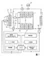
図1は、6気筒内燃機関1用の典型的な冷却システムの概略図である。内燃機関に加えて、ラジエータ2及び熱交換器3が冷却システム内に組み込まれている。ラジエータの冷却能力は、電気駆動式のファン4によって高めることができる。ファンのパワーを調整するために、制御ユニット5でファンの電気モータを閉ループ制御することができる。冷却されるクーラントは、送り管6によってラジエータから取り出され、クーラントポンプ7によって燃焼シリンダ9用の冷却ダクト(より詳細に図示せず)に供給するための冷却ライン8に送られる。加熱されたクーラントは、燃焼シリンダ9から戻りライン10を介してサーモスタット三方弁11に送られる。サーモスタット三方弁11の弁の位置に応じて、クーラントは、内燃機関からラジエータ戻り管12を介してラジエータ内に戻るか、あるいはラジエータバイパス管13とクーラントポンプ7とを介して再び内燃機関の冷却ライン8に戻る。 FIG. 1 is a schematic diagram of a typical cooling system for a six-cylinder
この場合、冷却システムは、サーモスタット三方弁11の弁の位置に応じて、公知の方法で、バイパス回路作動モードで、混合作動モード、又は、冷却回路作動モードで、作動されることが可能である。熱交換器3は、温度制御の遮断弁14を介して内燃機関の冷却システムの高温分岐管に接続される。遮断弁14の開放後の熱交換器を通したスループットは、加熱パワーを調整するために、追加の電気式クーラントポンプ15及びパルス幅変調(PWM)制御される遮断弁16で調整することができる。 In this case, the cooling system can be operated in a known manner, in the bypass circuit operating mode, in the mixing operating mode or in the cooling circuit operating mode, depending on the position of the valve of the thermostat three-way valve 11. . The
この場合、内燃機関のクーラントの温度レベルは、センサ信号をもとに制御を行う制御ユニット5によって設定される。マイクロコンピュータを有するロジック要素が制御ユニットに収容される。この制御ユニットは、エンジン制御用の制御ユニットに一体的に組み込まれることが好ましい。図2と図3で略述した制御アルゴリズムは、ロジック要素で実行されるソフトウェア(プログラム)の形態で実現されることが好ましい。制御アルゴリズムの入力変数として最も重要な動作データは、燃焼シリンダに導入される燃料量、エンジン回転数、吸気温度、外気温度、運転者タイプの分類及び車両の速度である。 In this case, the temperature level of the coolant of the internal combustion engine is set by the
燃料量は、直接噴射エンジンでは、測定又は制御された噴射量FJRATによって決定することができる。キャブレター式エンジンの場合、燃料量は、測定された吸気量MAF(空気質量)及び理論空燃比によって間接的に決定される。上述の動作データは、エンジン制御ユニットに通常格納されているか、あるいは燃焼行程を制御するためにエンジン制御ユニットによって検知され、収集される。運転者タイプの分類は、例えば、運転者に応じて異なる制御を行う自動変速機を有する車両で使用される。車両の内部のディスプレイ上の外気温度の表示は、最近、本出願人が製造する車両では一般的である。この結果、本発明を実施するために、既存のエンジン制御ユニット及び既存のエンジン制御ソフトウェアを利用することができ、内燃機関の動作データを準備又は決定するために、追加の出費は不要である。 The fuel quantity can be determined by the measured or controlled injection quantity FJRAT in a direct injection engine. In the case of a carburetor engine, the fuel amount is indirectly determined by the measured intake air amount MAF (air mass) and the stoichiometric air-fuel ratio. The operational data described above is usually stored in the engine control unit or is detected and collected by the engine control unit to control the combustion stroke. The classification of the driver type is used, for example, in a vehicle having an automatic transmission that performs different control depending on the driver. The indication of the outside temperature on the display inside the vehicle is recently common in vehicles manufactured by the applicant. As a result, existing engine control units and existing engine control software can be utilized to implement the present invention, and no additional expense is required to prepare or determine internal combustion engine operating data.
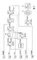
図2は、ソフトウェアアーキテクチャの単純化したマットラブ・シミュリンク(Matlab-Simulink)表示、及び設定すべきクーラント温度を本発明に従って決定するための信号フローチャートを示している。吸気温度21、空気流質量22、運転者タイプの分類23、エンジン回転数24、燃料噴射量25及び外気温度26を含む入力信号は、五段階の決定カスケードでさらに処理され、また現在の動作パラメータに整合されるクーラント設定温度27がそこから決定される。決定カスケードの各段階は、プログラム入力変数の関数として設定温度を決定して、計算するためのEDP(Electronic
Data Processing)プログラムから構成される。個々のソフトウェアプログラムは、以下にモジュールと称される。FIG. 2 shows a simplified Matlab-Simulink display of the software architecture and a signal flow chart for determining the coolant temperature to be set according to the present invention. Input signals including
Data Processing) program. Individual software programs are hereinafter referred to as modules.
この場合、五段階の決定カスケードは、ポート噴射によるエンジンでは、モジュールKE_ECT(ポート噴射器(Kanaleinspritzer)に従うエンジン冷却温度について)、ECT_FTK(運転者タイプの分類(Fahrertypklassifizierung)に従うエンジン冷却温度について)、ECT_AT(吸気温度(Ansauglufttemperatur)に従うエンジン冷却温度について)、ECT_VehSpd(車両速度に従うエンジン冷却温度について)及びモジュールECT_ExtAir(外気温度に従うエンジン冷却温度について)から構成される。 In this case, the five-stage decision cascade is for engines with port injection: modules KE_ECT (for engine cooling temperature according to port injector (Kanaleinspritzer)), ECT_FTK (for engine cooling temperature according to driver type classification (Fahrertypklassifizierung)), ECT_AT (For engine cooling temperature according to intake air temperature (Ansauglufttemperatur)), ECT_VehSpd (for engine cooling temperature according to vehicle speed) and module ECT_ExtAir (for engine cooling temperature according to outside air temperature).
直接噴射によるエンジンでは、燃料量は噴射量から決定される。これらのエンジンでは、モジュールDE_ECT(直接噴射(Dierekteinspritzung)に従うエンジン冷却温度について)が、モジュールKE_ECTの代わりに、第1のクーラント設定温度TMSoll1を計算するために使用される。制御アルゴリズムは、標準ベースで、ポート噴射器用ならびに直接噴射器用の両方のモジュールを含む。どちらのモジュールが使用されるかは、プログラムを用いて2つのモジュールの一方を作動することによって、エンジンの特性をベースにして設定される。この選択可能性は、図2による信号フローチャートでは、スイッチング要素28で示されている。この手順は、様々な種類の混合気形成のために1つの制御アルゴリズムを実施すればよく、前記アルゴリズムをそれぞれのエンジンバージョンに設定できるという利点を有する。 In an engine using direct injection, the fuel amount is determined from the injection amount. In these engines, the module DE_ECT (for engine cooling temperature according to Dierekteinspritzung) is used to calculate the first coolant set temperature TMSoll1 instead of the module KE_ECT. The control algorithm includes modules for both port injectors as well as direct injectors on a standards basis. Which module is used is set based on engine characteristics by operating one of the two modules using a program. This selectability is indicated by switching
燃料入力から計算される第1のクーラント設定温度TMSoll1は、エンジンの負荷に依存し、すなわち、エンジン回転数EngSpd及び燃料量の関数として105℃に又は80℃に設定される。第1のクーラント設定温度TMSoll1は、エンジン制御器からの運転者タイプの現在の分類FTKの関数として次のモジュールECT_FTKを用いて検討され、そこから、105℃又は80℃のクーラント温度が運転者タイプの分類に従って選択される。 The first coolant set temperature TMSoll1 calculated from the fuel input depends on the engine load, ie, is set to 105 ° C. or 80 ° C. as a function of the engine speed EngSpd and the fuel amount. The first coolant set temperature TMSoll1 is examined using the following module ECT_FTK as a function of the current classification FTK of the operator type from the engine controller, from which a coolant temperature of 105 ° C. or 80 ° C. is Selected according to the classification.
運転者タイプがスポーティ走行を好む人の分類に対して、80℃のクーラント温度がより広く用いられ、優先して選択される。この検討の結果が、第2のクーラント設定温度TMSoll2である。 A coolant temperature of 80 ° C. is more widely used and preferentially selected for the classification of people who prefer sporty driving. The result of this examination is the second coolant set temperature TMSoll2.
運転者タイプによる分類の後、吸気温度が決定カスケードの次の段階で考慮される。これは、モジュールECT_ATで行われる。吸気温度の感知は、渋滞状態を検出するために使用される。自動車が渋滞にあると検出された場合、クーラント設定温度を80℃又は90℃に下げることが望ましい。これは、吸気温度が40℃〜50℃の温度間隔にある基準値を超えた場合、クーラント温度を上述の2つの値の一方に下げることによって対応される。吸気温度を考慮した後の結果は、クーラント設定温度TMSoll3である。 After classification by driver type, the intake air temperature is considered in the next stage of the decision cascade. This is done in module ECT_AT. Intake air temperature sensing is used to detect congestion conditions. When it is detected that the automobile is congested, it is desirable to lower the coolant set temperature to 80 ° C or 90 ° C. This is dealt with by lowering the coolant temperature to one of the above two values when the intake air temperature exceeds a reference value in the temperature interval of 40 ° C. to 50 ° C. The result after considering the intake air temperature is the coolant set temperature TMSoll3.
決定されるこのクーラント設定温度TMSoll3は、車両の現在の速度を用いて、次のモジュールECT_VehSpdによって、決定カスケードで評価される。車両速度が第1の基準値、例えば120km/hを超えた場合、クーラント温度は90℃に設定され、また車両速度が第2の基準値、例えば160km/hを超えた場合、クーラント設定温度は80℃に設定される。 This determined coolant set temperature TMSoll3 is evaluated in a decision cascade by the next module ECT_VehSpd using the current speed of the vehicle. When the vehicle speed exceeds a first reference value, for example 120 km / h, the coolant temperature is set to 90 ° C., and when the vehicle speed exceeds a second reference value, for example 160 km / h, the coolant set temperature is Set to 80 ° C.
決定カスケードの最後の段階で、車両速度に従って評価されるクーラント設定温度TMSoll4が、外気温度を用いて評価され、決定される。この方法において、極端な環境状態、例えば極端な寒さが生じた場合、以前に取得されたクーラント設定温度を最終的に無視することができ、そして最終的に適用すべきクーラント設定温度TMSoll5を決定することができ、前記クーラント設定温度TMSoll5は、ファン4及びサーモスタット三方弁11用の作動手段に対する設定値変数として予め規定される。外部温度が、第1の基準値、例えば12℃を超えた場合、温度は、決定カスケードの最後の段階によって下げられない。温度が、第1の基準値、例えば、90℃のクーラント設定温度の場合、外気温度12℃未満に低下した場合、クーラント設定温度は外部温度に適合して変更される。外部温度がさらに低下した場合、また外部温度が、第2の基準値、例えばマイナス15℃未満に低下した場合、クーラント設定温度は他の影響変数と無関係に105℃に設定される。 In the final stage of the decision cascade, the coolant set temperature TMSoll4 evaluated according to the vehicle speed is evaluated and determined using the outside air temperature. In this way, in the event of extreme environmental conditions, such as extreme cold, the previously obtained coolant set temperature can eventually be ignored and finally the coolant set temperature TMSoll5 to be applied is determined. The coolant set temperature TMSoll5 is defined in advance as a set value variable for the operating means for the
第5の段階の後に最終的に存在するクーラント設定温度TMSoll5は、入力信号21、22、23、24、25、26及び車両速度と無関係に、例えば100秒の最小時間の間、ファン4及びサーモスタット三方弁11の作動用の設定値変数として保持される。この保持機能は、例えば、遅延手段又はプログラムの遅延ループを用いて実現することができる。図2の信号フローチャートでは、決定されるクーラント設定温度の保持機能は、タイミング遅延手段29によって表される。 The coolant set temperature TMSoll5 that finally exists after the fifth stage is independent of the input signals 21, 22, 23, 24, 25, 26 and the vehicle speed, for example for a minimum time of 100 seconds, the
図3は、本発明のさらなる実施態様を示すもので、具体的には、前述の制御アルゴリズムが故障した場合、フォールバックレベルの内燃機関の熱管理の補完を行う。フォールバックレベルへの切替の根拠となるものは、それに接続される作動手段によって点検されるファン4及びサーモスタット三方弁11用の特性信号がDisableになることである。この特性信号は、一般に、点検すべきプロセスで故障が決定されたかどうか設定される故障フラグである。故障フラグが設定された場合、図2による制御アルゴリズムで決定される可能なクーラント設定温度は、後続の制御器によって考慮されない。次に、内燃機関の冷却システムは、最大冷却力で連続的に運転されるか、あるいはクーラント温度は、存在するならば、余剰的に設けられたPID制御器を使用して従来の方法で単に温度制御して設定される。 FIG. 3 shows a further embodiment of the invention, in particular, complementing the thermal management of the fallback level internal combustion engine when the aforementioned control algorithm fails. The basis for switching to the fallback level is that the characteristic signal for the
この場合、図3の例示的な実施形態による故障検出動作は、Fail-Safeプログラムモジュールを使用するプログラミング手段によって、関連のデータ信号を監視することによって、クーラント温度を監視することによって、プログラム故障決定によって、または、モジュールTM_disableを使用して無効故障フラグを設定することによって実施される。代わりに、クーラント温度が、例えば108℃の予め規定された限界基準値を超えると直ちに、あるいは存在しないデータ信号又は許容されないデータ信号が、Fail-Safe信号フロー監視手段によって規定されると直ちに故障決定と判断される。故障の監視は、エンジンエレクトロニクスMEの制御ユニットの監視にも拡張することができる。制御ユニットは、利用可能な故障信号を生成する定期的自己試験を有し、信号フローを監視するためのモジュールを使用して、この信号も監視することができる。故障が信号フロー監視手段によって検出された場合、故障特性信号が決定段階TM_disableに送られる。次に、故障は、伝送された故障識別子によって決定段階で評価され、そして故障フラグを設定すべきかどうかについて決定が行われる。 In this case, the fault detection operation according to the exemplary embodiment of FIG. 3 is performed by a programmed fault determination by monitoring the coolant temperature by monitoring the associated data signal by means of programming using the Fail-Safe program module. Or by setting an invalid fault flag using the module TM_disable. Instead, a fault determination is made as soon as the coolant temperature exceeds a pre-defined limit reference value, eg 108 ° C., or as soon as a non-existent or unacceptable data signal is defined by the Fail-Safe signal flow monitoring means. It is judged. Fault monitoring can also be extended to engine electronics ME control unit monitoring. The control unit has a periodic self-test that generates an available fault signal, which can also be monitored using a module for monitoring the signal flow. If a fault is detected by the signal flow monitoring means, a fault characteristic signal is sent to the decision stage TM_disable. The fault is then evaluated at the decision stage by the transmitted fault identifier and a determination is made as to whether a fault flag should be set.
Claims (13)
Translated fromJapanese前記サーモスタット(11)の弁の作動ユニットはロジック要素(ロジック)によって作動され、前記サーモスタット(11)の弁の開放または閉鎖時間は、前記ロジック要素(ロジック)で実施される制御アルゴリズムによって決定される内燃機関(1)のクーラント回路のサーモスタット(11)を作動するための方法において、
前記制御アルゴリズムによって決定される閉ループ制御設定を用いて、前記冷却システムのクーラント温度が、内燃機関の運転パラメータの関数として3つの異なる温度レベルに設定され、この設定された閉ループ制御設定が、保持機能を使用して、予め規定された最小期間の間保持されることとを特徴とする方法。The circuit of bypassing the radiator (2) and the circuit passing through the radiator (2) can be switched by the closed loop temperature control by the valve of the thermostat (11), or mixing at a certain mixing ratio by the closed loop temperature control. You can select both in operation mode,
The valve operating unit of the thermostat (11) is operated by a logic element (logic), and the opening or closing time of the valve of the thermostat (11) is determined by a control algorithm implemented in the logic element (logic). In a method for operating a thermostat (11) of a coolant circuit of an internal combustion engine (1),
Using the closed-loop control settings determined by the control algorithm, the coolant temperature of the cooling system is set to three different temperature levels as a function of the operating parameters of the internal combustion engine, and the set closed-loop control settings are used as a holding function. And holding for a predefined minimum period of time.
−前記決定カスケードの第2の段階(ECT_FTK)で、105℃、90℃又は80℃の第2の温度設定値(TMSOLL2)が、前記第1の温度設定値(TMSOLL1)と前記運転者タイプの分類(FTK)に関する前記特性変数とから決定され、
−前記決定カスケードの第3の段階(ECT_AT)で、105℃、90℃又は80℃の第3の温度設定値(TMSOLL23)が、前記第2の温度設定値(TMSOLL2)と前記吸気温度とから決定され、
−前記決定カスケードの第4の段階(ECT_VehSpd)で、105℃、90℃又は80℃の第4の温度設定値(TMSOLL4)が、前記第3の温度設定値(TMSOLL3)と前記車両の速度(Veh−Spd)とから決定され、
−第5の段階(ECT_ExtAir)で、105℃、90℃又は80℃の第5の温度設定値(TMSOLL5)が、前記第4の温度設定値(TMSOLL4)と外気温度とから決定されることを特徴とする請求項5に記載の方法。-In the first stage of the decision cascade (KE_ECT), a first temperature setpoint (TMSOLL1) of 105 ° C, 90 ° C or 80 ° C is determined by the engine speed (EngSpd) of the cylinder and the fuel amount (MAF, FJRATE), and
-In the second stage of the decision cascade (ECT_FTK), a second temperature setpoint (TMSOLL2) of 105 ° C, 90 ° C or 80 ° C is changed between the first temperature setpoint (TMSOLL1) and the driver type Determined from the characteristic variables for classification (FTK),
-In the third stage (ECT_AT) of the decision cascade, a third temperature setpoint (TMSOLL23) of 105 ° C, 90 ° C or 80 ° C is obtained from the second temperature setpoint (TMSOLL2) and the intake air temperature. Determined,
-In the fourth stage of the decision cascade (ECT_VehSpd), a fourth temperature setpoint (TMSOLL4) of 105 ° C, 90 ° C or 80 ° C becomes the third temperature setpoint (TMSOLL3) and the speed of the vehicle ( Veh-Spd),
-In a fifth stage (ECT_ExtAir), a fifth temperature set value (TMSOLL5) of 105 ° C, 90 ° C or 80 ° C is determined from the fourth temperature set value (TMSOLL4) and the outside air temperature. 6. A method according to claim 5, characterized in that
−前記外部温度がマイナス15℃〜12℃の範囲にある場合、前記クーラント温度が、前記負荷の関数として90℃又は105℃に設定され、
−前記外部温度が12℃超である場合、前記クーラント温度が、前記負荷の関数として80℃又は105℃に調整されることを特徴とする請求項1〜6のいずれか1項に記載の方法。If the external temperature is below minus 15 ° C, the coolant temperature is set to 105 ° C irrespective of the load;
When the external temperature is in the range of minus 15 ° C. to 12 ° C., the coolant temperature is set to 90 ° C. or 105 ° C. as a function of the load;
The method according to any one of the preceding claims, wherein if the external temperature is above 12 ° C, the coolant temperature is adjusted to 80 ° C or 105 ° C as a function of the load. .
Applications Claiming Priority (2)
| Application Number | Priority Date | Filing Date | Title |
|---|---|---|---|
| DE10336599.0ADE10336599B4 (en) | 2003-08-08 | 2003-08-08 | Method for controlling a thermostat in a cooling circuit of an internal combustion engine |
| PCT/EP2004/008491WO2005017326A1 (en) | 2003-08-08 | 2004-07-29 | Heat management for an internal combustion engine |
Publications (1)
| Publication Number | Publication Date |
|---|---|
| JP2007501907Atrue JP2007501907A (en) | 2007-02-01 |
Family
ID=34089144
Family Applications (1)
| Application Number | Title | Priority Date | Filing Date |
|---|---|---|---|
| JP2006522293AAbandonedJP2007501907A (en) | 2003-08-08 | 2004-07-29 | Thermal management method for internal combustion engine |
Country Status (4)
| Country | Link |
|---|---|
| US (1) | US20060196451A1 (en) |
| JP (1) | JP2007501907A (en) |
| DE (1) | DE10336599B4 (en) |
| WO (1) | WO2005017326A1 (en) |
Cited By (4)
| Publication number | Priority date | Publication date | Assignee | Title |
|---|---|---|---|---|
| JP2013536539A (en)* | 2010-05-27 | 2013-09-19 | アプライド マテリアルズ インコーポレイテッド | Parts temperature control by controlling coolant flow rate and heater duty cycle |
| US9214315B2 (en) | 2010-01-29 | 2015-12-15 | Applied Materials, Inc. | Temperature control in plasma processing apparatus using pulsed heat transfer fluid flow |
| US9338871B2 (en) | 2010-01-29 | 2016-05-10 | Applied Materials, Inc. | Feedforward temperature control for plasma processing apparatus |
| US10274270B2 (en) | 2011-10-27 | 2019-04-30 | Applied Materials, Inc. | Dual zone common catch heat exchanger/chiller |
Families Citing this family (12)
| Publication number | Priority date | Publication date | Assignee | Title |
|---|---|---|---|---|
| GB2427482B (en)* | 2004-07-02 | 2007-05-02 | Ohm Ltd | Electromagnetic surveying |
| FR2901311A1 (en)* | 2006-05-16 | 2007-11-23 | Renault Sas | METHOD AND SYSTEM FOR CONTROLLING TEMPERATURE IN AN ENGINE |
| US7634323B2 (en)* | 2007-02-23 | 2009-12-15 | Toyota Motor Engineering & Manufacturing North America, Inc. | Optimization-based modular control system |
| US8849540B2 (en) | 2011-11-02 | 2014-09-30 | Honda Motor Co., Ltd. | Methods and systems for monitoring engine coolant temperature sensor |
| JP2014005894A (en)* | 2012-06-26 | 2014-01-16 | Suzuki Motor Corp | Shift control device of automatic transmission |
| DE102013005707B4 (en) | 2013-03-30 | 2018-01-18 | Audi Ag | Method for controlling and / or regulating the cooling capacity of a driver-type-influenced vehicle cooling system and corresponding vehicle cooling system |
| DE102015006365B4 (en)* | 2015-05-20 | 2021-09-30 | Deutz Aktiengesellschaft | Internal combustion engine with at least one electric motor |
| DE102017202638B4 (en) | 2017-02-20 | 2022-04-28 | Ford Global Technologies, Llc | Predictive thermal management for motor vehicles |
| US10662863B1 (en) | 2018-11-20 | 2020-05-26 | Caterpillar Inc. | Systems and methods for monitoring the performance of a heat exchanger |
| WO2021195029A1 (en)* | 2020-03-24 | 2021-09-30 | Cummins Inc. | Systems and methods for engine coolant temperature control |
| US12176844B2 (en) | 2021-03-16 | 2024-12-24 | Cummins Power Generation Limited | Systems and methods for genset coolant control |
| CN115234355B (en)* | 2022-08-02 | 2023-10-20 | 广州汽车集团股份有限公司 | Water temperature control method and water temperature control device |
Family Cites Families (33)
| Publication number | Priority date | Publication date | Assignee | Title |
|---|---|---|---|---|
| JPS62237023A (en)* | 1986-04-07 | 1987-10-17 | Mazda Motor Corp | Cooling water controller for engine |
| DE4109498B4 (en)* | 1991-03-22 | 2006-09-14 | Robert Bosch Gmbh | Device and method for controlling the temperature of an internal combustion engine |
| DE4324178A1 (en)* | 1993-07-19 | 1995-01-26 | Bayerische Motoren Werke Ag | Cooling system for an internal combustion engine of a motor vehicle with a thermostatic valve that contains an electrically heated expansion element |
| ES2112717B1 (en)* | 1993-07-19 | 1998-12-01 | Bayerische Motoren Werke Ag | COOLING ARRANGEMENT FOR AN INTERNAL COMBUSTION ENGINE OF AN AUTOMOBILE. |
| DE4409547C2 (en)* | 1993-07-19 | 1999-09-23 | Bayerische Motoren Werke Ag | Cooling system for an internal combustion engine of a motor vehicle with a thermostatic valve that contains an electrically heated expansion element |
| DE19504893B4 (en)* | 1995-02-14 | 2004-12-30 | Bayerische Motoren Werke Ag | Coolant temperature control system for the cooling system of an internal combustion engine |
| US5582138A (en)* | 1995-03-17 | 1996-12-10 | Standard-Thomson Corporation | Electronically controlled engine cooling apparatus |
| DE19728814A1 (en)* | 1997-07-05 | 1999-01-07 | Behr Thermot Tronik Gmbh & Co | Cooling system for an internal combustion engine of a motor vehicle |
| IT1293664B1 (en)* | 1997-08-01 | 1999-03-08 | C R F Societa Conosrtile Per A | COOLING SYSTEM FOR INTERNAL COMBUSTION ENGINE OF VEHICLE |
| JPH11117739A (en)* | 1997-10-09 | 1999-04-27 | Toyota Motor Corp | Cooling water circulation device for internal combustion engine |
| US6178928B1 (en)* | 1998-06-17 | 2001-01-30 | Siemens Canada Limited | Internal combustion engine total cooling control system |
| US6055947A (en)* | 1999-01-14 | 2000-05-02 | Tosok Corporation | Engine cooling water control system |
| IT1308421B1 (en)* | 1999-03-11 | 2001-12-17 | Fiat Ricerche | COOLING SYSTEM FOR AN INTERNAL COMBUSTION ENGINE. |
| DE19951362A1 (en)* | 1999-10-26 | 2001-05-03 | Bosch Gmbh Robert | Method for regulating the cooling water temperature of a motor vehicle with an internal combustion engine |
| JP4140160B2 (en)* | 2000-01-20 | 2008-08-27 | 株式会社デンソー | Cooling device for liquid-cooled internal combustion engine |
| US6520136B2 (en)* | 2000-09-13 | 2003-02-18 | Toyota Jidosha Kabushiki Kaisha | Warm-up control device for internal-combustion engine and warm-up control method |
| DE10145735B4 (en)* | 2000-09-18 | 2011-01-20 | DENSO CORPORATION, Kariya-shi | Cooling device for liquid-cooled internal combustion engine |
| US6364213B1 (en)* | 2001-04-18 | 2002-04-02 | Ford Global Technologies, Inc. | Engine cooling system |
| DE10155339A1 (en)* | 2001-11-10 | 2003-05-22 | Daimler Chrysler Ag | Method for operating an internal combustion engine and motor vehicle |
| JP3912104B2 (en)* | 2001-12-25 | 2007-05-09 | 三菱自動車工業株式会社 | Engine cooling system |
| KR100521913B1 (en)* | 2002-02-09 | 2005-10-13 | 현대자동차주식회사 | CONTROL METHOD OF Adjustable Electronic Thermostat |
| DE10215262B4 (en)* | 2002-04-06 | 2014-12-31 | Daimler Ag | Cooling system, in particular for a motor vehicle engine with indirect intercooling |
| DE10224063A1 (en)* | 2002-05-31 | 2003-12-11 | Daimler Chrysler Ag | Method for heat regulation of an internal combustion engine for vehicles |
| JP3932277B2 (en)* | 2002-10-18 | 2007-06-20 | 日本サーモスタット株式会社 | Control method of electronic control thermostat |
| US6764020B1 (en)* | 2003-02-28 | 2004-07-20 | Standard-Thomson Corporation | Thermostat apparatus for use with temperature control system |
| JP4103663B2 (en)* | 2003-03-31 | 2008-06-18 | トヨタ自動車株式会社 | Engine cooling system |
| DE10332947A1 (en)* | 2003-07-19 | 2005-02-03 | Daimlerchrysler Ag | Internal combustion engine for a motor vehicle |
| DE10335567A1 (en)* | 2003-07-31 | 2005-03-10 | Behr Gmbh & Co Kg | Circuit arrangement for cooling charge air and method for operating such a circuit arrangement |
| DE10337412A1 (en)* | 2003-08-14 | 2005-03-10 | Daimler Chrysler Ag | Method for controlling a thermostat |
| DE10337413A1 (en)* | 2003-08-14 | 2005-03-10 | Daimler Chrysler Ag | Method of regulating the flow of coolant with a heater shut-off valve |
| JP4196802B2 (en)* | 2003-10-07 | 2008-12-17 | 株式会社デンソー | Cooling water circuit |
| DE10348130A1 (en)* | 2003-10-16 | 2005-05-12 | Daimler Chrysler Ag | Cooling system for an internal combustion engine of a motor vehicle |
| DE10348133A1 (en)* | 2003-10-16 | 2005-05-12 | Daimler Chrysler Ag | Method for driving a fan with multiple characteristics and control program for the power control of the fan |
- 2003
- 2003-08-08DEDE10336599.0Apatent/DE10336599B4/ennot_activeExpired - Fee Related
- 2004
- 2004-07-29WOPCT/EP2004/008491patent/WO2005017326A1/enactiveApplication Filing
- 2004-07-29JPJP2006522293Apatent/JP2007501907A/ennot_activeAbandoned
- 2004-07-29USUS10/567,102patent/US20060196451A1/ennot_activeAbandoned
Cited By (7)
| Publication number | Priority date | Publication date | Assignee | Title |
|---|---|---|---|---|
| US9214315B2 (en) | 2010-01-29 | 2015-12-15 | Applied Materials, Inc. | Temperature control in plasma processing apparatus using pulsed heat transfer fluid flow |
| US9338871B2 (en) | 2010-01-29 | 2016-05-10 | Applied Materials, Inc. | Feedforward temperature control for plasma processing apparatus |
| US10854425B2 (en) | 2010-01-29 | 2020-12-01 | Applied Materials, Inc. | Feedforward temperature control for plasma processing apparatus |
| JP2013536539A (en)* | 2010-05-27 | 2013-09-19 | アプライド マテリアルズ インコーポレイテッド | Parts temperature control by controlling coolant flow rate and heater duty cycle |
| US9639097B2 (en) | 2010-05-27 | 2017-05-02 | Applied Materials, Inc. | Component temperature control by coolant flow control and heater duty cycle control |
| US10274270B2 (en) | 2011-10-27 | 2019-04-30 | Applied Materials, Inc. | Dual zone common catch heat exchanger/chiller |
| US10928145B2 (en) | 2011-10-27 | 2021-02-23 | Applied Materials, Inc. | Dual zone common catch heat exchanger/chiller |
Also Published As
| Publication number | Publication date |
|---|---|
| WO2005017326A1 (en) | 2005-02-24 |
| US20060196451A1 (en) | 2006-09-07 |
| DE10336599B4 (en) | 2016-08-04 |
| DE10336599A1 (en) | 2005-02-24 |
Similar Documents
| Publication | Publication Date | Title |
|---|---|---|
| JP2007501907A (en) | Thermal management method for internal combustion engine | |
| US7320434B2 (en) | Method of controlling electronic controlled thermostat | |
| US7010967B2 (en) | Thermostat malfunction detecting system for engine cooling system | |
| US7757649B2 (en) | Controller, cooling system abnormality diagnosis device and block heater determination device of internal combustion engine | |
| US6588380B2 (en) | Cooling system for a motor vehicle comprising a closing unit for the cooling airflow | |
| JP3932035B2 (en) | Abnormality diagnosis device for cooling system of internal combustion engine | |
| US6662761B1 (en) | Method for regulating the temperature of the coolant in an internal combustion engine using an electrically operated coolant pump | |
| JP4999863B2 (en) | Method and apparatus for controlling the initial opening of a thermostat for adjusting the temperature of an internal combustion engine | |
| US20160281586A1 (en) | Cooling system for engine | |
| US6817321B2 (en) | Method for controlling electronically-controlled thermostat | |
| US6851399B2 (en) | Method for monitoring a coolant circuit of an internal combustion engine | |
| US7299993B2 (en) | Apparatus for detecting a failure of a thermostat for an engine | |
| JP2006525462A (en) | Extended fan operation | |
| US7455239B2 (en) | Cooling system for an internal combustion engine of a motor vehicle | |
| US20070029396A1 (en) | Method for triggering a thermostat | |
| JP5878052B2 (en) | Engine control device | |
| KR100410518B1 (en) | a thermostat diagnosis method of engine for vehicles | |
| JP2007177707A (en) | Idling rotation speed control device for internal combustion engine | |
| JP4110523B2 (en) | Vehicle heating system |
Legal Events
| Date | Code | Title | Description |
|---|---|---|---|
| A621 | Written request for application examination | Free format text:JAPANESE INTERMEDIATE CODE: A621 Effective date:20070501 | |
| RD02 | Notification of acceptance of power of attorney | Free format text:JAPANESE INTERMEDIATE CODE: A7422 Effective date:20070710 | |
| RD04 | Notification of resignation of power of attorney | Free format text:JAPANESE INTERMEDIATE CODE: A7424 Effective date:20070720 | |
| RD04 | Notification of resignation of power of attorney | Free format text:JAPANESE INTERMEDIATE CODE: A7424 Effective date:20070710 | |
| A762 | Written abandonment of application | Free format text:JAPANESE INTERMEDIATE CODE: A762 Effective date:20080715 |