JP2007334379A - Processing equipment - Google Patents
Processing equipmentDownload PDFInfo
- Publication number
- JP2007334379A JP2007334379AJP2004293041AJP2004293041AJP2007334379AJP 2007334379 AJP2007334379 AJP 2007334379AJP 2004293041 AJP2004293041 AJP 2004293041AJP 2004293041 AJP2004293041 AJP 2004293041AJP 2007334379 AJP2007334379 AJP 2007334379A
- Authority
- JP
- Japan
- Prior art keywords
- processing
- lighting
- information
- requested
- color
- Prior art date
- Legal status (The legal status is an assumption and is not a legal conclusion. Google has not performed a legal analysis and makes no representation as to the accuracy of the status listed.)
- Pending
Links
Images


Classifications
- G—PHYSICS
- G06—COMPUTING OR CALCULATING; COUNTING
- G06F—ELECTRIC DIGITAL DATA PROCESSING
- G06F1/00—Details not covered by groups G06F3/00 - G06F13/00 and G06F21/00
- G06F1/16—Constructional details or arrangements
- G06F1/18—Packaging or power distribution
- G06F1/181—Enclosures
- H—ELECTRICITY
- H04—ELECTRIC COMMUNICATION TECHNIQUE
- H04L—TRANSMISSION OF DIGITAL INFORMATION, e.g. TELEGRAPHIC COMMUNICATION
- H04L12/00—Data switching networks
- H04L12/28—Data switching networks characterised by path configuration, e.g. LAN [Local Area Networks] or WAN [Wide Area Networks]
- H04L12/2803—Home automation networks
- H04L12/2816—Controlling appliance services of a home automation network by calling their functionalities
- H04L12/2821—Avoiding conflicts related to the use of home appliances
- H—ELECTRICITY
- H04—ELECTRIC COMMUNICATION TECHNIQUE
- H04L—TRANSMISSION OF DIGITAL INFORMATION, e.g. TELEGRAPHIC COMMUNICATION
- H04L67/00—Network arrangements or protocols for supporting network services or applications
- H04L67/01—Protocols
- H04L67/10—Protocols in which an application is distributed across nodes in the network
- H—ELECTRICITY
- H04—ELECTRIC COMMUNICATION TECHNIQUE
- H04L—TRANSMISSION OF DIGITAL INFORMATION, e.g. TELEGRAPHIC COMMUNICATION
- H04L12/00—Data switching networks
- H04L12/28—Data switching networks characterised by path configuration, e.g. LAN [Local Area Networks] or WAN [Wide Area Networks]
- H04L12/2803—Home automation networks
- H04L12/2816—Controlling appliance services of a home automation network by calling their functionalities
- H04L12/282—Controlling appliance services of a home automation network by calling their functionalities based on user interaction within the home
Landscapes
- Engineering & Computer Science (AREA)
- Signal Processing (AREA)
- Computer Networks & Wireless Communication (AREA)
- Theoretical Computer Science (AREA)
- General Physics & Mathematics (AREA)
- General Engineering & Computer Science (AREA)
- Physics & Mathematics (AREA)
- Human Computer Interaction (AREA)
- Computer Security & Cryptography (AREA)
- Automation & Control Theory (AREA)
- Power Engineering (AREA)
- Computer Hardware Design (AREA)
- Computer And Data Communications (AREA)
- Management, Administration, Business Operations System, And Electronic Commerce (AREA)
- User Interface Of Digital Computer (AREA)
Abstract
Translated fromJapaneseDescription
Translated fromJapanese本発明は、ネットワークにおける処理装置の利用技術に関し、特に、他の機器から処理を依頼されている装置を利用する場合の利便性を向上させる技術に関する。 The present invention relates to a technology for using a processing device in a network, and more particularly, to a technology for improving convenience when using a device requested to be processed by another device.
従来から、ネットワーク上の複数のコンピュータを利用し、分散して処理を行わせる技術が提供されている(特許文献1)。
この技術により、複数のコンピュータに並列処理を行わせ、1台1台の性能は低くとも、高速に大量の処理を行うことが出来るようになっている。
また、近年、一般家庭においては、一部の家電が情報処理機能を持つに至っており、このような家庭内の機器をネットワークで結び、その家電の処理機能を利用しようとする技術が提案されている(特許文献2)。すなわち、家庭内ネットワークで分散処理コンピューティングを行う技術である。例えば、画像データ等をトランスコードする場合のような時間を要する処理を行う場合に、他の家電の処理機能を利用して短時間で処理を完了させるような例である。
With this technology, a plurality of computers can perform parallel processing, and a large amount of processing can be performed at high speed even if the performance of each computer is low.
In recent years, some home appliances have information processing functions in general households, and a technology has been proposed to connect such home devices with a network and use the processing functions of the home appliances. (Patent Document 2). In other words, it is a technique for performing distributed processing computing in a home network. For example, in the case of performing a time-consuming process such as transcoding image data or the like, the process is completed in a short time using a processing function of another home appliance.
しかし、家庭内においては、ユーザである家人が、家電を本来の目的に使用する場合が当然ながら発生し、さらに、節電のために電源を切る場合もある。このような場合に、その家電が他の機器のために何かの処理を行っていたとすれば、家電本来の目的を果たすことができず、また、突然電源を切った場合には、処理中の機器にハードディスクのクラッシュが起こったり、処理を依頼した側の機器においては、処理の手戻り等の不都合が生ずる場合がある。 However, in the home, a householder who is a user naturally uses the home appliance for the original purpose, and the power may be turned off to save power. In such a case, if the home appliance is doing something for other devices, it cannot fulfill its intended purpose, and if it is suddenly turned off, In some cases, a hard disk crash may occur in this device, or inconveniences such as reworking of the processing may occur in the device that requested the processing.
また、将来においては、1つの機器が複数のユーザを識別し、使用しているユーザによって、表示メッセージや画面が変わるデジタルテレビやハイブリッドレコーダ、ゲーム機などの家電、すなわち、マルチユーザ対応の家電が登場することが予測される。
そこで、本発明は、家庭内の情報機器が、家庭内ネットワーク上の他の機器から処理を依頼されて実行している場合に、家人に対して、その機器を本来の目的に使用してよいのか、電源を切ってよいのか等の判断材料を簡便に通知する装置の提供を目的とする。In the future, a single device will identify multiple users, and the display message and screen will change depending on the user being used, such as digital TVs, hybrid recorders, game consoles, that is, multi-user compatible home appliances. Expected to appear.
Therefore, according to the present invention, when an information device in the home is requested and executed by another device on the home network, the device may be used for the purpose of the householder. It is an object of the present invention to provide an apparatus for simply notifying materials such as whether to turn off the power.
上記課題を解決する為に、本発明の処理装置は、他の処理装置とネットワーク接続されている処理装置であって、ネットワーク上の他の処理装置から、処理の依頼を受付ける受付手段と、前記処理装置の本来の目的を達成する処理を行っていない間に、前記受付手段により受付けた処理を実行する実行手段と、前記実行手段で、依頼された処理を実行していることを報知する報知手段とを備えることを特徴とする。 In order to solve the above problems, a processing device of the present invention is a processing device connected to another processing device over a network, and accepting means for receiving a processing request from another processing device on the network; An executing means for executing the process accepted by the accepting means and a notification for notifying that the requested process is being executed by the executing means while the process for achieving the original purpose of the processing apparatus is not performed. Means.
本発明に係る処理装置は、上述の構成を備えることにより、処理装置は、ネットワーク上の他の装置から依頼された処理を実行していることを報知することができるので、ユーザは、その装置を使用するか否かの判断をすることができるようになる。
また、前記処理装置は、点灯機器を備え、前記受付手段は、更に、点滅間隔を含む点灯情報を受け付け、前記報知手段は、前記実行手段が処理の実行を開始したときに、前記点灯情報に含まれる点滅間隔に基づき、前記点灯機器を点滅させ、前記処理を開始したことを報知することとしてもよい。Since the processing device according to the present invention has the above-described configuration, the processing device can notify that the processing requested by another device on the network is being performed. It becomes possible to determine whether or not to use.
In addition, the processing device includes a lighting device, the receiving unit further receives lighting information including a blinking interval, and the notification unit includes the lighting information when the execution unit starts executing the process. Based on the included blinking interval, the lighting device may blink to notify the start of the process.
さらに、前記処理装置は、点灯機器を備え、前記受付手段は、更に、点灯色を含む点灯情報を受け付け、前記報知手段は、前記実行手段が処理の実行を開始したときに、前記点灯情報に含まれる点灯色に基づき、前記点灯機器を点灯させ、前記処理を開始したことを報知することとしてもよい。
これにより処理装置は、ネットワーク上の他の装置から依頼された処理を実行しているときには、自装置の点灯機器を所定の間隔で点滅、または、所定の色で点灯することができるので、ユーザは、その装置を使用するか否かの判断をすることができるようになる。Furthermore, the processing device includes a lighting device, the receiving unit further receives lighting information including a lighting color, and the notification unit includes the lighting information when the execution unit starts executing the process. Based on the included lighting color, the lighting device may be turned on to notify the start of the process.
As a result, when the processing device is executing processing requested by another device on the network, the lighting device of the own device can blink at a predetermined interval or can be lit in a predetermined color. Can determine whether or not to use the device.
また、前記処理装置は、更に、点灯機器と、前記他の処理装置と、点滅間隔を含む点灯情報とを対応付けた情報を記憶する記憶手段とを備え、前記受付手段は、更に、処理を依頼した前記他の処理装置を示す情報を含む依頼元情報を受け付け、
前記報知手段は、前記実行手段が処理の実行を開始したときに、当該処理の依頼元情報で示される他の処理装置に対応した点灯属性情報に含まれる点滅間隔に基づいて、前記点灯機器を点滅させ、開始した処理の依頼元を報知することとしてもよい。In addition, the processing device further includes a storage device that stores information in which lighting devices, the other processing devices, and lighting information including blinking intervals are associated with each other, and the reception unit further performs processing. Accept request source information including information indicating the other processing device requested,
When the execution unit starts executing the process, the notification unit sets the lighting device based on the blinking interval included in the lighting attribute information corresponding to another processing device indicated by the request source information of the process. It is good also as making it blink and notifying the request origin of the process which started.
さらに、前記他の処理装置と、点灯色を含む点灯情報とを対応付けた情報を記憶する記憶手段とを備え、前記受付手段は、更に、処理を依頼した前記他の処理装置を示す情報を含む依頼元情報を受け付け、前記報知手段は、前記実行手段が処理の実行を開始したときに、当該処理の依頼元情報で示される他の処理装置に対応した点灯属性情報に含まれる点灯色に基づいて、前記点灯機器を点灯させ、開始した処理の依頼元を報知することとしてもよい。 Furthermore, the storage unit stores information that associates the other processing device with lighting information including a lighting color, and the reception unit further includes information indicating the other processing device that has requested processing. The requesting unit information is received, and when the execution unit starts executing the process, the notification unit sets the lighting color included in the lighting attribute information corresponding to the other processing device indicated by the requesting unit information of the process. Based on this, the lighting device may be turned on to notify the requester of the started process.
これにより処理装置は、ネットワーク上の他の装置から依頼された処理を実行しているときには、依頼元に応じて自装置の点灯機器を所定の間隔で点滅、または、所定の色で点灯することができるので、ユーザは、その装置がどの装置に依頼された処理をしているかを知ることができ、その装置を使用するか否かの判断をすることができるようになる。 As a result, when the processing device is executing a process requested by another device on the network, the lighting device of the own device blinks at a predetermined interval or lights in a predetermined color according to the request source. Therefore, the user can know to which apparatus the apparatus is performing the requested processing, and can determine whether or not to use the apparatus.
<概要>
本発明に係る処理装置は、本来の処理の空き時間に、ネットワーク上の他の装置からの依頼を受けて処理を行うものであり、その依頼された処理を行っていることをユーザに知らせる機能を持つものである。
本発明の特徴は、インジケータの色や点滅速度などで、どの装置から以来された処理をしているか等をユーザに視覚的に瞬時に認識させる点にある。<Overview>
The processing device according to the present invention performs processing in response to a request from another device on the network during the free time of the original processing, and a function for notifying the user that the requested processing is being performed. It has something.
The feature of the present invention is that the user can visually recognize instantly the processing performed from which device, etc., by the color of the indicator, the blinking speed, and the like.
ユーザは、わざわざコマンドを入力する等しなくても、その装置が他の装置のために処理をしていて、他の装置とは何であるか等が一目でわかる。従って、不注意から処理を止めてしまったりすることがなくなり、また、故意に処理を止めさせることができるようになる。
以下、本発明に係る処理装置の実施形態について説明する。Even if the user does not bother to input a command, the user can know at a glance what the other device is doing for the other device. Therefore, the process is not stopped due to carelessness, and the process can be stopped intentionally.
Hereinafter, embodiments of a processing apparatus according to the present invention will be described.
本実施形態では、ハイブリッドレコーダ1000において、内部のHDD(Hard Disk Drive)に記録されているコンテンツを、他の記憶媒体であるDVD(Digital Versatile Disk)に出力する場合を説明する。HDDとDVDでは、記憶するデータの圧縮方式が異なり、コンテンツの変換処理は時間を要する処理であるとする。 In the present embodiment, a case will be described in which content recorded in an internal HDD (Hard Disk Drive) is output to a DVD (Digital Versatile Disk) which is another storage medium in the
<構成>
図1は、本発明にかかる処理装置を用いて処理を行っている例を表す図である。
ホームネットワーク9000で、デジタルテレビ8000、パソコン7000、ハイブリッドレコーダ1000およびゲーム機2000がつながっている。
ハイブリッドレコーダ1000のHDDに記録されているコンテンツを、DVDに出力している。<Configuration>
FIG. 1 is a diagram illustrating an example in which processing is performed using a processing apparatus according to the present invention.
A
The content recorded on the HDD of the
ここで、HDDには圧縮方式MPEG2(Moving Picture Experts Group phase2)でコンテンツが記録され、DVDにはMPEG4(Moving Picture Experts Group phase4)で記憶されるものとする。
図1では、ハイブリッドレコーダ1000が、コンテンツの圧縮方式の変換処理の一部を、ゲーム機2000に依頼し、ゲーム機2000が依頼された処理を行っているところを表している。Here, it is assumed that the content is recorded on the HDD by the compression scheme MPEG2 (Moving Picture Experts Group phase 2), and the DVD is stored by the MPEG4 (Moving Picture Experts Group phase 4).
FIG. 1 shows that the
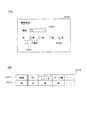
ゲーム機2000は、本来の処理ではない処理、すなわちゲームの処理ではないコンテンツの変換処理を行っているので、ゲーム機2000のインジケータに青色を点灯し、点滅させているものとする。このゲーム機2000のインジケータ部分を拡大図2900で示す。
図2は、ハイブリッドレコーダ1000、ゲーム機2000および点灯情報サーバ装置4000の構成を示す機能ブロック図である。Since the
FIG. 2 is a functional block diagram showing configurations of
ハイブリッドレコーダ1000は、処理を依頼する側であり、また、ゲーム機2000は処理を依頼される側であり、いわゆるサーバ装置とクライアント装置といえる。この例では、ハイブリッドレコーダ1000がサーバ側となっているが、その時に応じて、ネットワーク上のいずれの装置も、サーバ側にもクライアント側にも成り得る。
また、点灯情報サーバ装置4000は、各機器を示すインジケータの表示色を管理しているものである。本実施形態では、パソコン7000を点灯情報サーバ装置4000とする。The
In addition, the lighting
ハイブリッドレコーダ1000は、ユーザインターフェース部1100、点灯情報登録処理部1200、点灯情報記憶部1300、制御部1400、依頼ジョブデータ作成部1500および送受信部1600で構成される。
ユーザインターフェース部1100は、ハイブリッドレコーダ1000の操作パネル、リモコン、ディスプレイ、インジケータ等を含み、ユーザへの情報提示、ユーザからの指示の授受等、ユーザと情報のやり取りを行う機能を有する。The
The
本実施形態では、機器を表す点灯情報を登録するための画面などを表示し、ユーザの設定内容を取得する(図4(A)および図5(A)参照)。
次に、点灯情報登録処理部1200は、ユーザインターフェース部1100でユーザが入力した点灯情報を点灯情報記憶部1300に保存する機能を有する。
また、点灯情報登録処理部1200は、ユーザが入力した点灯情報を、点灯情報サーバ装置4000に送受信部1600を介して送信する機能を有する。In the present embodiment, a screen for registering lighting information representing the device is displayed, and the setting contents of the user are acquired (see FIGS. 4A and 5A).
Next, the lighting information
The lighting information
点灯情報記憶部1300は、点灯情報登録処理部1200から受け取ったデータを記憶しておく機能を有する。具体的には、後述する色データ3110および点滅間隔データ3210を記憶している(図4(B)および図5(B)参照)。
制御部1400は、ハイブリッドレコーダ1000の各機能を制御する機能を有する。ハイブリッドレコーダ1000は、通常のハイブリッドレコーダが有する録画機能、再生機能、ダビング機能等を有し、HDDとDVDの双方に対応しているものとする。これらの通常有する機能は図示していない。The lighting
The
また、ハイブリッドレコーダ1000は、MPEG2でHDDに記録されているコンテンツを、MPEG4に変換しDVDに記憶する機能を有し、その変換処理の一部の処理を、ホームネットワーク9000で繋がっている家電の1つ、本実施形態ではゲーム機2000に依頼して行う機能を有する。
制御部1400は、これらの通常有する機能を制御する他、本発明に係る機能を制御する。本発明に係る機能とは、例えば、ハイブリッドレコーダ1000がネットワーク上の他の機器に処理を依頼する場合に、依頼がハイブリッドレコーダ1000からの依頼であることを他の機器のユーザに認識させる為の情報を、処理の依頼と同時に送信することである。The
The
依頼ジョブデータ作成部1500は、制御部1400からの依頼を受けて、他の機器に処理を依頼するジョブデータを作成する機能を有する。
送受信部1600は、クライアント装置であるゲーム機2000とのデータのやり取りを行う機能を有する。
ゲーム機2000は、ユーザインターフェース部2100、点灯制御部2200、依頼ジョブ実行部2300、依頼ジョブデータ解析部2400および送受信部2500で構成される。The requested job
The transmission /
The
ユーザインターフェース部2100は、ゲーム機2000のコントローラ、操作パネル、インジケータ等を含み、ユーザへの情報提示、ユーザからのゲーム指示の授受等、ユーザと情報のやり取りを行う機能を有する。
本実施形態では、主に、ゲーム機2000の本来の処理、すなわちゲームの実行処理、以外の処理を行っていることを表すインジケータをいう。The
In the present embodiment, it mainly refers to an indicator indicating that processing other than the original processing of the
点灯制御部2200は、ユーザインターフェース部2100のインジケータの点灯と消去、および、色と点灯間隔を制御する機能を有する。
依頼ジョブ実行部2300は、ホームネットワーク9000上の他の機器から依頼された処理であるジョブを行う機能を有する。
依頼ジョブデータ解析部2400は、ホームネットワーク9000上の他の機器から依頼されたジョブデータを、依頼されたジョブデータの部分と点灯データの部分とに分けて、それぞれの情報に基づいて、依頼ジョブ実行部2300と点灯制御部2200とに処理を依頼する機能を有する。The
The requested job execution unit 2300 has a function of performing a job that is a process requested by another device on the
The requested job
また、依頼ジョブデータ解析部2400は、自機が本来の処理を実行中であるか否かを判断する機能を備えており、本来の処理を実行していない間に、依頼ジョブ実行部2300と点灯制御部2200に処理を依頼する。
送受信部2500は、サーバ装置であるハイブリッドレコーダ1000とのデータのやり取りを行う機能を有する。Further, the requested job
The transmission /
次に、点灯情報サーバ装置4000は、ユーザインターフェース部4100、点灯情報記憶部4200、および送受信部4300で構成される。
ユーザインターフェース部4100は、パソコン7000のディスプレイ、キーボード、インジケータ等を含み、ユーザへの情報提示、ユーザからの指示の授受等、ユーザと情報のやり取りを行う機能を有する。Next, the lighting
The
本実施形態では、主に、各機器の点灯情報を登録するための画面などを表示し、ユーザの設定内容を取得する機能をいう(図6(A)参照)。
点灯情報記憶部4200は、ユーザインターフェース部4100から受け取った各機器の色データを記憶しておく機能を有する。具体的には、後述する機器色データ3310を記憶している(図6(B)参照)。In the present embodiment, it mainly refers to a function for displaying a screen for registering lighting information of each device and acquiring user setting contents (see FIG. 6A).
The lighting
送受信部4300は、サーバ装置であるハイブリッドレコーダ1000とデータのやり取りを行う機能を有する。
<データ>
以下、本処理装置で用いる主なデータについて、図3から図6を用いて説明する。
図3は、依頼ジョブデータ1510の構成および内容例を示す図である。The transmission /
<Data>
Hereinafter, main data used in this processing apparatus will be described with reference to FIGS.
FIG. 3 is a diagram showing a configuration and example contents of the requested
この依頼ジョブデータ1510は、ハイブリッドレコーダ1000から、ゲーム機2000にジョブを依頼する場合のデータであり、依頼ジョブデータ作成部1500において作成される。
依頼ジョブデータ1510は、ジョブデータ1511と点灯データ1512とで構成される。The requested
The requested
ジョブデータ1511は、ハイブリッドレコーダ1000がゲーム機2000に依頼するジョブのデータである。例えば、MPEG2で作成されているコンテンツの部分と命令文などで構成される。
点灯データ1512は、インジケータの点灯情報であり、このデータに基づいてゲーム機のインジケータが点灯する。The
The
この点灯データ1512は、色1521と点滅間隔1522とで構成される。色1521は、インジケータの点灯色であり、点滅間隔1522は、インジケータの点滅の間隔である。
次に、図4から図6は、インジケータの点灯に関する情報の設定画面の例と、設定情報の構成および内容例を示した図である。The
Next, FIGS. 4 to 6 are diagrams showing an example of a setting screen for information related to lighting of the indicator, and an example of the configuration and contents of the setting information.
本実施形態では、インジケータの色でどの機器に依頼された処理を実行しているかを示し、インジケータの点滅の早さで、その処理は家人の内の誰が依頼した処理であるかを示すこととする。また、誰が依頼したかは、各機器ごとに設定できることとする。
図4(A)は、処理を依頼する側の機器において、自機の依頼であることを表すインジケータの色を設定する画面の例であり、図4(B)は、その色データの構成および内容例である。In the present embodiment, the color of the indicator indicates to which device the requested process is being executed, and the indicator blinks quickly, indicating that the process is requested by a householder. To do. In addition, it can be set for each device who requested.
FIG. 4A is an example of a screen for setting the color of an indicator indicating that it is a request of the own device in the device that requests processing, and FIG. 4B shows the configuration of the color data and It is a content example.
色登録画面3100は、各装置それぞれで表示し、その装置を示す色を指定する。
例では、ハイブリッドレコーダ1000の色登録を行っているところを示している。「青」のチェックボックス3101にチェックを入れている。尚、ここでは、「緑」は既に「PC使用」とメッセージ3103が表示されており、「緑」のチェックボックス3102にはチェックが出来なくなっている。The
In the example, the color registration of the
色データ3110は、自機の色を示している。例では、ハイブリッドレコーダの色登録画面3100で登録した、「青」が設定されている。この色データ3110は、各機器の点灯情報記憶部1300に記憶される。
次に、図5(A)は、処理を依頼するユーザが、自分の依頼であることを表すインジケータの点滅間隔を設定する画面の例であり、図5(B)は、その点滅間隔データの構成および内容例である。The
Next, FIG. 5A is an example of a screen in which the user who requests processing sets the blinking interval of the indicator indicating that it is his request, and FIG. 5B is a diagram of the blinking interval data. It is a structure and an example of contents.
点滅間隔設定画面3200は、各装置でそれぞれ表示し、その装置を利用しているユーザを示す点滅間隔を指定する。
例では、ハイブリッドレコーダ1000において、ユーザ名3201「ICHIRO」を示す点滅間隔の登録を行っているところを示している。「遅い」のチェックボックス3202にチェックを入れている。A blinking
In the example, the
点滅間隔データ3210は、ユーザ名3211と点滅間隔3212とで構成され、ユーザ毎の点滅間隔を示している。例では、ユーザ名3211が「PAPA」で表されるユーザは、点滅間隔3212が「速い」となっている。これは、例えば、ユーザ名「PAPA」が、ハイブリッドレコーダ1000でコンテンツをHDDからDVDにダビングをしている場合に、ゲーム機がハイブリッドレコーダから依頼されたトランスコード処理の一部を行っている時は、ゲーム機のインジケータが「速い」間隔で点滅することを意味する。 The blinking
この点滅間隔データ3210は、色データ3110と共に、各機器の点灯情報記憶部1300に記憶される。
色登録画面3100および点滅間隔設定画面3200は、ハイブリッドレコーダ1000のディスプレイまたは、デジタルテレビ8000の画面に表示される。
また、この登録および設定は、登録しようとする機器にディスプレイが具備されていなくても、ボタン等でも設定できてもよく、また、ネットワークに接続されている他の機器、例えばパソコンなどのディスプレイを利用して登録できることとしてもよい。The blinking
The
In addition, this registration and setting may be set with a button or the like, even if the device to be registered does not have a display, and other devices connected to the network, such as a display such as a personal computer, may be set. It is good also as being able to register using.
次に、図6(A)は、各機器を示す色を、一括で登録する画面の例であり、図6(B)は、各機器の色データの構成および内容例である。
機器色登録画面3300は、点灯情報サーバ装置4000で表示し、各機器を示すインジケータの色を指定する。
例では、点灯情報サーバ装置4000において、機器3301「TV」を示す色の登録を行っている。「TV」とは、ホームネットワーク9000に繋がっているデジタルテレビ8000を指す。Next, FIG. 6A is an example of a screen for collectively registering colors indicating each device, and FIG. 6B is a configuration and example of contents of color data of each device.
The device
In the example, the lighting
色「赤」のチェックボックス3303にチェックを入れている。また、色「青」のチェックボックスはチェックできなくなっており、「ハイブリッドレコーダ使用」3302と表示されている。
機器色データ3310は、機器3311と色3312とで構成される。各機器を表す色を示している。例では、機器3311が「TV」で表される機器、すなわち、デジタルテレビは、色3312が「赤」となっている。これは、例えば、機器「TV」が処理をゲーム機2000に依頼している場合に、ゲーム機がTVから依頼された処理、例えば、MPEG2で符号化された映像データを復号する処理を行っている時は、インジケータが「赤」で点灯されることを意味する。A
The
この機器色データ3310は、点灯情報サーバ装置4000の点灯情報記憶部4200に記憶される。
また、機器色登録画面3300は、点灯情報サーバ装置4000のディスプレイに表示される。点灯情報サーバ装置4000にディスプレイが具備されていなくても、ボタン等でも設定できてもよく、また、ネットワークに接続されている他の機器、例えばデジタルテレビなどのディスプレイを利用して登録できることとしてもよい。The
The device
本実施形態では、機器の色登録を、各機器と点灯情報サーバとの双方から登録を行うことができるが、最新の登録が有効であるとする。
<動作>
以下、上述した、サーバ装置であるハイブリッドレコーダ1000、クライアント装置であるゲーム機2000および点灯情報サーバ装置であるパソコン4000の動作について図7〜図9を用いて説明する。In this embodiment, device color registration can be performed from both the device and the lighting information server, but the latest registration is valid.
<Operation>
Hereinafter, the operations of the
具体的には、次の3つの動作について説明する。1つは、サーバ装置であるハイブリッドレコーダ1000が、クライアント装置であるゲーム機2000に対してジョブの依頼を行う処理である。2つ目は、依頼を受けたクライアント装置であるゲーム機2000が行う処理である。3つ目は、各機器で色の登録を行う処理である。
<1.サーバ装置のジョブ依頼処理>
図7を用いて説明する。図7は、サーバ装置のジョブ依頼処理を表すフローチャートである。Specifically, the following three operations will be described. One is processing in which the
<1. Job request processing of server device>
This will be described with reference to FIG. FIG. 7 is a flowchart showing job request processing of the server apparatus.
ユーザ名「ICIRO」である家人が、ハイブリッドレコーダ1000で、コンテンツをHDDからDVDにダビングするとする。ユーザは、自分のユーザ名を指定すると共に、リモコンのダビングのボタンを押下する。本実施形態では、リモコンの特定のボタンを押下することでユーザ名を指定することが出来るものとする。
ユーザからのダビングの指示を受け付けたユーザインターフェース部1100は、制御部1400にその旨を通知する。It is assumed that a householder with the user name “ICIRO” uses the
Upon receiving the dubbing instruction from the user, the
ダビングを行う旨の通知を受けた制御部1400は、MPEG2からMPEG4へのトランスコード処理うち、他の機器へ依頼する処理、すなわち依頼するジョブを決める。また、同時にホームネットワーク9000に繋がっている機器のうち、その情報処理機能が使われていない機器の1つを、処理を依頼する機器として決定する(ステップS10)。本実施形態では、決定された機器は、ゲーム機2000とする。 The
制御部1400は依頼ジョブデータ作成部1500に、依頼するジョブの内容と依頼する機器の情報を渡し、依頼ジョブのデータを作成するよう指示する。
データ作成の指示を受けた依頼ジョブデータ作成部1500は、受け取ったジョブ内容と依頼する機器情報とから依頼する依頼ジョブデータ1510を作成する(ステップS11)。The
Upon receiving the data creation instruction, the requested job
また、同時に、点灯データ1512を作成するために、点灯情報記憶部1300から点灯情報を読み出す(ステップS12)。具体的には、色データ3110と点滅間隔データ3210とを読み出し、点滅間隔データ3210のなかのユーザ名3211「ICHIRO」に対応する点滅間隔3212「遅い」と色データ3110とを基に、点灯データ1520を作成する。 At the same time, lighting information is read from the lighting
依頼ジョブデータ作成部1500は、作成したジョブデータ1511と点灯データ1512とから依頼ジョブデータ1510を作成し(ステップS13)、 作成した依頼ジョブデータ1510を、送受信部1600を介して、依頼する機器であるゲーム機2000に送信する(ステップS14)。
<2.クライアント装置の処理>
図8を用いて説明する。図8は、クライアント装置の処理を表すフローチャートである。The requested job
<2. Processing of client device>
This will be described with reference to FIG. FIG. 8 is a flowchart showing the processing of the client device.
依頼ジョブデータ1510を受信した(ステップS20)ゲーム機2000の送受信部2500は、受信したデータを依頼ジョブデータ解析部2400に渡す。
受信した依頼ジョブデータ1510を受け取った依頼ジョブデータ解析部2400は、依頼ジョブデータ1510をジョブデータ1511と点灯データ1512に分離し、ジョブデータ1511を依頼ジョブ実行部2300に渡す。また、点灯情報を点灯制御部2200に渡し、点灯を開始する旨通知する(ステップS21)。Upon receiving the requested job data 1510 (step S20), the transmission /
Upon receiving the received requested
ジョブデータ1511を受け取った依頼ジョブ実行部2300は、依頼されたジョブを実行する(ステップS24)。
一方、点灯を開始する旨の通知を受けた点灯制御部2200は、ユーザインターフェース部2100に指示を出し、インジケータを点灯データ1512に基づいて、点灯させる(ステップS22)。例では、ゲーム機2000のインジケータが、青色で遅く点滅する。The requested job execution unit 2300 that has received the
On the other hand, the
実行しているジョブが終了したら(ステップS23)、依頼ジョブ実行部2300は、点灯制御部2200に対して、ジョブが終了した旨を通知する。
ジョブが終了した旨の通知を受けた点灯制御部2200は、ユーザインターフェース部2100に点灯を停止する旨の指示を出す(ステップS25)。例では、ゲーム機2000のインジケータの点灯が停止する。When the job being executed ends (step S23), the requested job execution unit 2300 notifies the
The
<3.各機器での色登録処理>
図9を用いて説明する。図9は、各機器での色の登録処理を表すフローチャートである。
ここでは、ハイブリッドレコーダ1000が、色を登録する場合を説明する。
まず、ユーザは、色を登録する為の色登録画面3100を表示する操作を行う。表示操作を受け付けたユーザインターフェース部1100は、点灯情報登録処理部1200に、最新の機器色データ3310を要求する。<3. Color registration processing on each device>
This will be described with reference to FIG. FIG. 9 is a flowchart showing color registration processing in each device.
Here, a case where the
First, the user performs an operation of displaying a
最新の機器色データ3310を要求された点灯情報登録処理部1200は、送受信部を介して、点灯情報サーバ装置4000に機器色データ3310を要求する。
点灯情報サーバ装置4000は、点灯情報記憶部4200から機器色データ3310を読み出し、ハイブリッドレコーダ1000に返す。点灯情報登録処理部1200は、送受信部1600を介して、機器色データ3310を取得する(ステップS30)。The lighting information
The lighting
機器色データ3310を取得した点灯情報登録処理部1200は、ユーザインターフェース部1100に最新の機器色データ3310を渡す。
ユーザインターフェース部1100は、受け取った最新の機器色データ3310を基に、色登録画面を表示し、ユーザからの入力を得る(ステップS31)。
ユーザからの入力を取得したユーザインターフェース部1100は、取得した色を、点灯情報登録処理部1200に渡す。例では、青である。The lighting information
The
The
色を受け取った点灯情報登録処理部1200は、この色を自装置の色として、色データ3110を作成し、点灯情報記憶部1300に保存する(ステップS32)。
また、同時に、点灯情報登録処理部1200は、この色と自装置の識別情報とを、点灯情報サーバ装置4000に送信する(ステップS33)。
色と自装置の識別情報とを受信した点灯情報サーバ装置4000は、点灯情報記憶部4200に記憶している機器色データ3310の該当する機器の色を書き換える。The lighting information
At the same time, the lighting information
The lighting
<補足>
以上、本発明に係る処理装置について実施形態に基づいて説明したが、この処理装置を部分的に変形することもでき、本発明は上述の実施形態に限られないことは勿論である。即ち、
(1)実施形態では、点灯情報サーバ装置で、点灯情報を一括管理することとしているが、各装置で自装置の色のみを管理し、各装置の色はユーザが管理することとしてもよい。
(2)実施形態では、インジケータの色で各装置を識別し、点滅間隔でユーザを識別することとしているが、これに限らない。例えば、処理の重要度を色で表すなどとしてもよい。すなわち、インジケータの色と点滅間隔で、様々な情報を報知することができる。<Supplement>
The processing apparatus according to the present invention has been described above based on the embodiment. However, the processing apparatus can be partially modified, and the present invention is not limited to the above-described embodiment. That is,
(1) In the embodiment, the lighting information server apparatus collectively manages the lighting information. However, each apparatus may manage only the color of its own apparatus, and the color of each apparatus may be managed by the user.
(2) In the embodiment, each device is identified by the color of the indicator and the user is identified by the blinking interval, but this is not a limitation. For example, the degree of importance of processing may be expressed by color. That is, various information can be notified by the color of the indicator and the blinking interval.
例えば、クライアント装置が、複数の演算装置などを有している場合などは、依頼された処理を行うのに使用している演算装置の数などを表してもよく、また、使用している演算装置の数が多いほど、速く点滅するようにしてもよい。
(3)実施形態では、装置に付属したインジケータを点灯することで、処理中である等の情報を報知することとしているが、中継機器やケーブル、コンセントなどでもよい。For example, when the client device has a plurality of arithmetic devices, etc., it may represent the number of arithmetic devices used to perform the requested processing, etc. You may make it blink more rapidly, so that there are many apparatuses.
(3) In the embodiment, the indicator attached to the apparatus is turned on to notify information such as being processed, but a relay device, a cable, an outlet, or the like may be used.
また、視覚的に知覚できるものに限ることはなく、聴覚、触覚等により知覚できるものであってもよい。例えば、依頼元の機器に応じて異なる音楽が鳴る、振動するなどでもよい。
(4)実施形態では、インジケータは、1つの表示灯としているが(図1参照)、複数の表示灯で構成されていてもよい。また、表示灯の大きさは、同じ大きさでも、それぞれが異なる大きさであってもよく、その配置も直線的、円形等様々な形状であってもよい。Moreover, it is not restricted to what can be visually perceived, and what can be perceived by hearing, tactile sense, or the like may be used. For example, different music may sound or vibrate depending on the requesting device.
(4) In the embodiment, the indicator is a single indicator lamp (see FIG. 1), but may be composed of a plurality of indicator lamps. In addition, the size of the indicator lamp may be the same size or may be different from each other, and the arrangement may be various shapes such as a linear shape and a circular shape.
すなわち、表示灯の色と点滅間隔と表示灯の数で、様々な情報を報知する。
例えば、その複数の表示灯のうち、点灯している表示灯の数により、様々な情報を表すこととしてもよい。具体的には、依頼元毎に点灯する表示灯の個数を変える、依頼された処理の重要度で点灯する表示灯の個数を変えるなどである。
またさらに、点灯する表示灯の個数で、依頼された処理の進み具合などを表してもよい。この場合は、クライアント装置側で、例えば、依頼ジョブ実行部で処理の進み具合を管理して、点灯する表示灯の個数を制御する。
(5)実施形態では、サーバ装置は、点灯情報を付加したジョブデータをクライアント装置に送信しているが、サーバ装置の識別子等を付加したジョブデータを送信することとしてもよい。That is, various information is notified by the color of the indicator lamp, the blinking interval, and the number of indicator lights.
For example, various information may be represented by the number of indicator lights that are lit among the plurality of indicator lights. Specifically, the number of indicator lights that are turned on for each request source is changed, or the number of indicator lights that are turned on is changed according to the importance of the requested process.
Furthermore, the progress of requested processing may be represented by the number of indicator lights to be lit. In this case, on the client device side, for example, the progress of processing is managed by the request job execution unit, and the number of indicator lights to be lit is controlled.
(5) In the embodiment, the server device transmits the job data to which the lighting information is added to the client device. However, the server device may transmit the job data to which the identifier of the server device is added.
この場合は、例えば、クライアント装置側で、サーバ装置の識別子と点灯情報を対応付けた表などを記憶しておき、その表の該当する点灯情報を基に、インジケータを点灯する。
このサーバ装置の識別子と点灯情報を対応付けた表は、各装置がお互いに自装置の情報を登録し合う事で作成することとしてもよい。具体的には、各装置が自装置の識別子と自装置を表す点灯情報とを、他の装置に送信し合い、各装置において、送られてきた情報を基に、識別子と点灯情報の対応表を作成し記憶しておく。例えば、新しい装置がネットワークに登録された時点で、対応表を作成し直すことで、常に最新の情報を共有することができる。
(6)実施形態では、依頼された処理を実行している場合に、インジケータを点灯することとしているが、その場合に限らない。In this case, for example, on the client device side, a table in which the identifier of the server device is associated with the lighting information is stored, and the indicator is lit based on the corresponding lighting information in the table.
The table in which the identifier of the server device and the lighting information are associated with each other may be created by each device registering its own device information. Specifically, each device transmits its own identifier and lighting information representing the own device to other devices, and each device uses a correspondence table between the identifier and the lighting information based on the sent information. Create and remember. For example, when a new device is registered in the network, the latest information can always be shared by recreating the correspondence table.
(6) In the embodiment, the indicator is turned on when the requested process is being executed, but this is not a limitation.
例えば、ジョブを依頼された時、依頼されたジョブを実行する直前、依頼されたジョブが完了した時などであってもよい。
(7)実施形態では、原則として、装置ごとにインジケータの色を変え、ユーザごとに点滅間隔を異なるものとしているが、2つ以上の装置や2人以上のユーザが、重複する色、同じ点滅間隔であることとしてもよい。
(8)実施形態では、クライアント装置は、1つのサーバ装置から処理を依頼されることとしているが、複数のサーバ装置から処理を依頼されることも可能であることとしてもよい。For example, it may be when a job is requested, immediately before the requested job is executed, or when the requested job is completed.
(7) In the embodiment, in principle, the color of the indicator is changed for each device, and the blinking interval is different for each user. However, two or more devices or two or more users have overlapping colors and the same blinking. It may be an interval.
(8) In the embodiment, the client device is requested to process from one server device, but may be requested to process from a plurality of server devices.
この場合、クライアント装置は複数のサーバ装置から依頼される処理を、1つずつ順に行う方法のほか、マルチタスク処理で行ってももちろん良い。
マルチタスク処理で依頼された処理を行う場合、インジケータの点灯は、依頼を行った全てのサーバ装置から送信された点灯情報に基づく点灯処理を順次行う。これにより、複数のサーバ装置からの依頼を受けている場合でも、どの装置から依頼された処理をしているか等をユーザは視覚的に瞬時に認識することができる。
(9)本発明に係る処理装置は、様々な分散コンピューティング環境に適用が可能であることはもちろんである。In this case, the client device may of course execute multi-task processing in addition to a method of sequentially performing processing requested from a plurality of server devices one by one.
When performing the requested process in the multitask process, the lighting of the indicator sequentially performs the lighting process based on the lighting information transmitted from all the server apparatuses that have requested. As a result, even when requests from a plurality of server devices are received, the user can visually recognize instantly which device is performing the requested processing.
(9) The processing apparatus according to the present invention can be applied to various distributed computing environments.
例えば、複数の機器同士を、光ファイバ等の高速なネットワークで接続し、他の機器の計算資源やメモリ等を、あたかも自機の資源のように利用可能な分散コンピューティング環境においても、適用可能である。
(10)実施形態で示した処理装置の各機能を実現させる為の各制御処理(図2等参照)をCPUに実行させる為のプログラムを、記録媒体に記録し又は各種通信路等を介して、流通させ頒布することもできる。このような記録媒体には、ICカード、光ディスク、フレキシブルディスク、ROM、フラッシュメモリ等がある。流通、頒布されたプログラムは、機器におけるCPUで読み取り可能なメモリ等に格納されることにより利用に供され、そのCPUがそのプログラムを実行することにより実施形態で示した処理装置の各機能が実現される。
(11)尚、クライアント装置における依頼ジョブ実行部2300、依頼ジョブデータ解析部2400、点灯制御部2200等の各機能ブロックは典型的には集積回路であるLSIとして実現される。これらは個別に1チップ化されても良いし、一部又は全てを含むように1チップ化されても良い。サーバ装置における、点灯情報登録処理部1200、点灯情報記憶部1300、制御部1400、依頼ジョブデータ作成部1500も同様に個別に又は1チップ化されたLSIとして実現される。For example, it can be applied in a distributed computing environment in which multiple devices are connected to each other via a high-speed network such as optical fiber, and the computing resources and memory of other devices can be used as if they were resources of the device itself. It is.
(10) A program for causing the CPU to execute each control process (see FIG. 2 and the like) for realizing each function of the processing device shown in the embodiment is recorded on a recording medium or via various communication paths. It can also be distributed and distributed. Such a recording medium includes an IC card, an optical disk, a flexible disk, a ROM, a flash memory, and the like. The distributed and distributed program is used by being stored in a CPU-readable memory or the like in the device, and the CPU executes the program to realize each function of the processing device shown in the embodiment. Is done.
(11) Note that each functional block such as the requested job execution unit 2300, the requested job
ここでは、LSIとしたが、集積度の違いにより、IC、システムLSI、スーパーLSI、ウルトラLSIと呼称されることもある。
また、集積回路化の手法はLSIに限るものではなく、専用回路又は汎用プロセサで実現してもよい。LSI製造後に、プログラムすることが可能なFPGA(Field Programmable Gate Array)や、LSI内部の回路セルの接続や設定を再構成可能なリコンフィギュラブル・プロセッサー を利用しても良い。The name used here is LSI, but it may also be called IC, system LSI, super LSI, or ultra LSI depending on the degree of integration.
Further, the method of circuit integration is not limited to LSI's, and implementation using dedicated circuitry or general purpose processors is also possible. An FPGA (Field Programmable Gate Array) that can be programmed after manufacturing the LSI or a reconfigurable processor that can reconfigure the connection and setting of circuit cells inside the LSI may be used.
さらには、半導体技術の進歩又は派生する別技術によりLSIに置き換わる集積回路化の技術が登場すれば、当然、その技術を用いて機能ブロックの集積化を行ってもよい。バイオ技術の適応等が可能性としてありえる。 Further, if integrated circuit technology comes out to replace LSI's as a result of the advancement of semiconductor technology or a derivative other technology, it is naturally also possible to carry out function block integration using this technology. Biotechnology can be applied.
分散処理を行っている可能性のあるシステムにおいて、ユーザが特定の装置を使用できるか否かの判断を行う必要が生じた場合に、特に有用である。 This is particularly useful when it is necessary to determine whether a user can use a specific device in a system that may be performing distributed processing.
1000 ハイブリッドレコーダ
1100 2100 4100 ユーザインターフェース部
1200 点灯情報登録処理部
1300 点灯情報記憶部
1400 制御部
1500 依頼ジョブデータ作成部
1510 依頼ジョブデータ
1600 2500 4300 送受信部
2000 ゲーム機
2200 点灯制御部
2300 依頼ジョブ実行部
2400 依頼ジョブデータ解析部
2900 拡大図
3100 色登録画面
3110 色データ
3200 点滅間隔設定画面
3210 点滅間隔データ
3300 機器色登録画面
3310 機器色データ
4000 点灯情報サーバ装置
4200 点灯情報記憶部
7000 パソコン
8000 デジタルテレビ
9000 ホームネットワーク1000
Claims (8)
Translated fromJapaneseネットワーク上の他の処理装置から、処理の依頼を受付ける受付手段と、
前記処理装置の本来の目的を達成する処理を行っていない間に、前記受付手段により受付けた処理を実行する実行手段と、
前記実行手段で、依頼された処理を実行していることを報知する報知手段と
を備えることを特徴とする処理装置。A processing device connected to another processing device via a network,
Accepting means for accepting processing requests from other processing devices on the network;
An executing means for executing the process accepted by the accepting means while not performing the process for achieving the original purpose of the processing device;
An informing means for informing that the requested means is executing the requested process.
前記受付手段は、更に、点滅間隔を含む点灯情報を受け付け、
前記報知手段は、前記実行手段が処理の実行を開始したときに、前記点灯情報に含まれる点滅間隔に基づき、前記点灯機器を点滅させ、前記処理を開始したことを報知する
ことを特徴とする請求項1記載の処理装置。The processing apparatus includes a lighting device,
The receiving means further receives lighting information including a blinking interval,
When the execution means starts execution of the process, the notification means flashes the lighting device based on the blinking interval included in the lighting information, and notifies that the process has started. The processing apparatus according to claim 1.
前記受付手段は、更に、点灯色を含む点灯情報を受け付け、
前記報知手段は、前記実行手段が処理の実行を開始したときに、前記点灯情報に含まれる点灯色に基づき、前記点灯機器を点灯させ、前記処理を開始したことを報知する
ことを特徴とする請求項1記載の処理装置。The processing apparatus includes a lighting device,
The reception means further receives lighting information including a lighting color,
The informing means turns on the lighting device based on a lighting color included in the lighting information when the executing means starts execution of the process, and notifies that the process has started. The processing apparatus according to claim 1.
前記他の処理装置と、点滅間隔を含む点灯情報とを対応付けた情報を記憶する記憶手段とを備え、
前記受付手段は、更に、処理を依頼した前記他の処理装置を示す情報を含む依頼元情報を受け付け、
前記報知手段は、前記実行手段が処理の実行を開始したときに、当該処理の依頼元情報で示される他の処理装置に対応した点灯属性情報に含まれる点滅間隔に基づいて、前記点灯機器を点滅させ、開始した処理の依頼元を報知する
ことを特徴とする請求項1記載の処理装置。The processing device further includes a lighting device,
Storage means for storing information that associates the other processing device with lighting information including a blinking interval;
The accepting means further accepts request source information including information indicating the other processing apparatus that has requested processing,
When the execution unit starts executing the process, the notification unit sets the lighting device based on the blinking interval included in the lighting attribute information corresponding to another processing device indicated by the request source information of the process. The processing apparatus according to claim 1, wherein the processing apparatus is blinked to notify a requester of the started process.
前記受付手段は、更に、処理を依頼した前記他の処理装置を示す情報を含む依頼元情報を受け付け、
前記報知手段は、前記実行手段が処理の実行を開始したときに、当該処理の依頼元情報で示される他の処理装置に対応した点灯属性情報に含まれる点灯色に基づいて、前記点灯機器を点灯させ、開始した処理の依頼元を報知する
ことを特徴とする請求項1記載の処理装置。Storage means for storing information that associates the other processing device with lighting information including a lighting color;
The accepting means further accepts request source information including information indicating the other processing apparatus that has requested processing,
When the execution unit starts execution of the process, the notification unit determines the lighting device based on the lighting color included in the lighting attribute information corresponding to another processing device indicated by the request source information of the process. The processing apparatus according to claim 1, wherein the processing apparatus is turned on to notify a requester of the started processing.
ことを特徴とする請求項1記載の処理装置。The processing apparatus according to claim 1, wherein the process received by the receiving unit is a process of encoding image data.
ことを特徴とする請求項1記載の処理装置。The processing device according to claim 1, wherein the processing device is a home appliance, and performs processing as home appliance and other processing.
前記処理装置は、
点灯機器と、
ネットワーク上の他の処理装置から、処理の依頼と点滅間隔を示す情報を含む点灯情報とを受け付け、
を受付ける受付手段と、
前記処理装置の本来の処理を行っていない間に、前記受付手段により受付けた処理を実行する実行手段と、
前記実行手段が処理の実行を開始したときに、前記受信手段で受け取った点灯情報に基づき、前記点灯機器を点滅させ、前記処理を開始したことを報知する報知手段と
自装置の識別情報と自装置と対応付ける点灯情報とを、前記サーバ装置に送信する手段を備え、
前記サーバ装置は、
前記処理装置から、前記処理装置の識別情報と点灯情報とを受信した場合に、受信した処理装置と点灯情報とを対応させて記憶する記憶手段
を備えることを特徴とする処理システム。A processing system comprising a server device and a plurality of processing devices communicating with the server device,
The processor is
Lighting equipment,
Accepts a request for processing and lighting information including information indicating a blinking interval from other processing devices on the network,
Accepting means for accepting,
Execution means for executing processing received by the receiving means while not performing the original processing of the processing device;
When the execution means starts executing the process, based on the lighting information received by the receiving means, the lighting device blinks to notify the start of the process, the identification information of the device itself, Means for transmitting lighting information associated with the device to the server device;
The server device
A storage system comprising: storage means for storing the received processing device and lighting information in association with each other when the processing device identification information and lighting information are received from the processing device.
Priority Applications (3)
| Application Number | Priority Date | Filing Date | Title |
|---|---|---|---|
| JP2004293041AJP2007334379A (en) | 2004-10-05 | 2004-10-05 | Processing equipment |
| US11/597,415US7969322B2 (en) | 2004-10-05 | 2005-09-20 | Processor |
| PCT/JP2005/017310WO2006038455A1 (en) | 2004-10-05 | 2005-09-20 | Processor |
Applications Claiming Priority (1)
| Application Number | Priority Date | Filing Date | Title |
|---|---|---|---|
| JP2004293041AJP2007334379A (en) | 2004-10-05 | 2004-10-05 | Processing equipment |
Publications (1)
| Publication Number | Publication Date |
|---|---|
| JP2007334379Atrue JP2007334379A (en) | 2007-12-27 |
Family
ID=36142534
Family Applications (1)
| Application Number | Title | Priority Date | Filing Date |
|---|---|---|---|
| JP2004293041APendingJP2007334379A (en) | 2004-10-05 | 2004-10-05 | Processing equipment |
Country Status (3)
| Country | Link |
|---|---|
| US (1) | US7969322B2 (en) |
| JP (1) | JP2007334379A (en) |
| WO (1) | WO2006038455A1 (en) |
Families Citing this family (7)
| Publication number | Priority date | Publication date | Assignee | Title |
|---|---|---|---|---|
| JP5061541B2 (en)* | 2006-09-04 | 2012-10-31 | 日本電気株式会社 | Information processing system, information processing method, and program thereof |
| US9125255B2 (en) | 2012-05-03 | 2015-09-01 | Abl Ip Holding Llc | Networked architecture for system of lighting devices having sensors, for intelligent applications |
| US9137879B2 (en) | 2012-08-01 | 2015-09-15 | Abl Ip Holding Llc | Networked system of intelligent lighting devices with sharing of processing resources of the devices with other entities |
| US9504132B2 (en) | 2013-05-28 | 2016-11-22 | Abl Ip Holding Llc | Distributed processing using resources of intelligent lighting elements of a lighting system |
| US9612585B2 (en) | 2013-05-28 | 2017-04-04 | Abl Ip Holding Llc | Distributed building control system |
| US9462663B2 (en) | 2013-05-28 | 2016-10-04 | Abl Ip Holding Llc | Interactive user interface functionality for lighting devices or system |
| US9980351B2 (en) | 2013-08-12 | 2018-05-22 | Abl Ip Holding Llc | Lighting element-centric network of networks |
Family Cites Families (24)
| Publication number | Priority date | Publication date | Assignee | Title |
|---|---|---|---|---|
| JP3547781B2 (en)* | 1993-12-29 | 2004-07-28 | 株式会社東芝 | Image data transmission / reception device |
| US6067168A (en) | 1996-02-23 | 2000-05-23 | Sharp Kabushiki Kaisha | Shared memory image forming system |
| JP3299880B2 (en)* | 1996-02-23 | 2002-07-08 | シャープ株式会社 | Image forming system |
| US5978829A (en)* | 1996-11-05 | 1999-11-02 | A.T. & T. Corporation | Apparatus and methods for sharing idle workstations |
| US6268845B1 (en)* | 1997-06-11 | 2001-07-31 | Compaq Computer Corporation | Bezel button controls over USB |
| JPH11127478A (en)* | 1997-10-23 | 1999-05-11 | Matsushita Electric Ind Co Ltd | Mobile communication terminal |
| JP3318289B2 (en) | 1999-08-10 | 2002-08-26 | 松下電送システム株式会社 | Home network gateway equipment |
| JP2001325238A (en) | 2000-05-16 | 2001-11-22 | Hitachi Ltd | Processing progress display method in distributed object system |
| JP2001339484A (en)* | 2000-05-29 | 2001-12-07 | Nec Saitama Ltd | Folding type portable terminal |
| US6526491B2 (en) | 2001-03-22 | 2003-02-25 | Sony Corporation Entertainment Inc. | Memory protection system and method for computer architecture for broadband networks |
| US7231500B2 (en) | 2001-03-22 | 2007-06-12 | Sony Computer Entertainment Inc. | External data interface in a computer architecture for broadband networks |
| US6809734B2 (en) | 2001-03-22 | 2004-10-26 | Sony Computer Entertainment Inc. | Resource dedication system and method for a computer architecture for broadband networks |
| US7233998B2 (en) | 2001-03-22 | 2007-06-19 | Sony Computer Entertainment Inc. | Computer architecture and software cells for broadband networks |
| US7516334B2 (en) | 2001-03-22 | 2009-04-07 | Sony Computer Entertainment Inc. | Power management for processing modules |
| US6826662B2 (en) | 2001-03-22 | 2004-11-30 | Sony Computer Entertainment Inc. | System and method for data synchronization for a computer architecture for broadband networks |
| US7093104B2 (en) | 2001-03-22 | 2006-08-15 | Sony Computer Entertainment Inc. | Processing modules for computer architecture for broadband networks |
| US6720863B2 (en)* | 2001-08-16 | 2004-04-13 | Wildseed Ltd. | Mobile electronic communication device with lights to indicate received messages |
| JP4112196B2 (en)* | 2001-08-24 | 2008-07-02 | 株式会社リコー | Facsimile device and communication control device |
| US20040204151A1 (en)* | 2002-12-30 | 2004-10-14 | Sivakumar Muthuswamy | Method and apparatus for advising a user of a wireless device as to a connection status thereof |
| JP4374610B2 (en)* | 2003-04-18 | 2009-12-02 | カシオ計算機株式会社 | Imaging apparatus, image data storage method, and program |
| TWI278829B (en)* | 2003-10-28 | 2007-04-11 | Yamaha Corp | Tone generator device and portable phone using the same, and method for driving light emitting elements |
| US7546357B2 (en)* | 2004-01-07 | 2009-06-09 | Microsoft Corporation | Configuring network settings using portable storage media |
| US6993618B2 (en)* | 2004-01-15 | 2006-01-31 | Super Talent Electronics, Inc. | Dual-mode flash storage exchanger that transfers flash-card data to a removable USB flash key-drive with or without a PC host |
| US7769141B2 (en)* | 2005-09-23 | 2010-08-03 | Sorenson Communications, Inc. | Method and system for visual spatial caller identification |
- 2004
- 2004-10-05JPJP2004293041Apatent/JP2007334379A/enactivePending
- 2005
- 2005-09-20WOPCT/JP2005/017310patent/WO2006038455A1/ennot_activeCeased
- 2005-09-20USUS11/597,415patent/US7969322B2/enactiveActive
Also Published As
| Publication number | Publication date |
|---|---|
| US20080071933A1 (en) | 2008-03-20 |
| WO2006038455A1 (en) | 2006-04-13 |
| US7969322B2 (en) | 2011-06-28 |
Similar Documents
| Publication | Publication Date | Title |
|---|---|---|
| US20240149163A1 (en) | Software-Enabled Mobile Game Controller with Integrated Platform Operating Service | |
| JP5282447B2 (en) | Information processing apparatus, information processing method, program, and information processing system | |
| JP6013366B2 (en) | Virtualization embedded device | |
| US10025644B2 (en) | Information processing device and information processing system | |
| US20160317924A1 (en) | Information Processing Device and Information Processing System | |
| JP2008146495A (en) | Display control system, display controller, display control method, display control program, image output device, image output method, image output program, and display device | |
| WO2024097301A1 (en) | System and method for rich content browsing multitasking on device operating systems with multitasking limitations | |
| US20200374344A1 (en) | Information Processing Device and Information Processing System | |
| WO2013186971A1 (en) | Information processing device | |
| EP4611913A1 (en) | System and method for rich content browsing multitasking on device operating systems with multitasking limitations | |
| WO2015063966A1 (en) | Information processing system and information processing device | |
| US10286312B2 (en) | Information processing device and information processing system | |
| WO2011070734A1 (en) | Format conversion server, reproduction device and information reproduction system | |
| JP2007334379A (en) | Processing equipment | |
| JP2013051519A (en) | Information processing apparatus, information processing method, program, and information processing system | |
| CN112528051B (en) | Method, display device and server for publishing a singing work | |
| JP5140097B2 (en) | Device operation system, operation terminal, operated device, device operation method, device operation program, and recording medium | |
| JP2010056966A (en) | Server for transmitting image content, image display device, method of transmitting image content, and method of displaying image | |
| JP2015050709A (en) | Controller, control method and program | |
| CN114915833B (en) | Display control method, display device and terminal device | |
| KR102812546B1 (en) | Information processing device and image display method | |
| JP5120042B2 (en) | Information processing apparatus, information processing method, program, and information processing system | |
| KR100939809B1 (en) | How to Configure Computer Aids and User Interfaces | |
| JP2010193257A (en) | Server, remote operation system, transmission system selecting method, program, and recording medium | |
| JP6495976B2 (en) | Information processing apparatus and information display control method |