JP2007324681A - Devices connected to the IEEE serial bus - Google Patents
Devices connected to the IEEE serial busDownload PDFInfo
- Publication number
- JP2007324681A JP2007324681AJP2006149656AJP2006149656AJP2007324681AJP 2007324681 AJP2007324681 AJP 2007324681AJP 2006149656 AJP2006149656 AJP 2006149656AJP 2006149656 AJP2006149656 AJP 2006149656AJP 2007324681 AJP2007324681 AJP 2007324681A
- Authority
- JP
- Japan
- Prior art keywords
- connection
- physical connection
- bus
- bandwidth usage
- connected devices
- Prior art date
- Legal status (The legal status is an assumption and is not a legal conclusion. Google has not performed a legal analysis and makes no representation as to the accuracy of the status listed.)
- Withdrawn
Links
- 230000008859changeEffects0.000abstractdescription66
- 230000009467reductionEffects0.000description19
- 230000005540biological transmissionEffects0.000description12
- 238000000034methodMethods0.000description11
- 230000008569processEffects0.000description10
- 238000001514detection methodMethods0.000description9
- 238000012546transferMethods0.000description6
- 230000015654memoryEffects0.000description5
- 238000004891communicationMethods0.000description2
- 230000006870functionEffects0.000description2
- 238000012545processingMethods0.000description2
- 230000001360synchronised effectEffects0.000description2
- 230000001174ascending effectEffects0.000description1
- 230000001419dependent effectEffects0.000description1
- 230000000694effectsEffects0.000description1
- 238000012986modificationMethods0.000description1
- 230000004048modificationEffects0.000description1
- 238000011946reduction processMethods0.000description1
- 238000000547structure dataMethods0.000description1
Images


Classifications
- H—ELECTRICITY
- H04—ELECTRIC COMMUNICATION TECHNIQUE
- H04L—TRANSMISSION OF DIGITAL INFORMATION, e.g. TELEGRAPHIC COMMUNICATION
- H04L12/00—Data switching networks
- H04L12/28—Data switching networks characterised by path configuration, e.g. LAN [Local Area Networks] or WAN [Wide Area Networks]
- H04L12/40—Bus networks
- H04L12/40052—High-speed IEEE 1394 serial bus
- H04L12/40065—Bandwidth and channel allocation
- H—ELECTRICITY
- H04—ELECTRIC COMMUNICATION TECHNIQUE
- H04L—TRANSMISSION OF DIGITAL INFORMATION, e.g. TELEGRAPHIC COMMUNICATION
- H04L12/00—Data switching networks
- H04L12/28—Data switching networks characterised by path configuration, e.g. LAN [Local Area Networks] or WAN [Wide Area Networks]
- H04L12/40—Bus networks
- H04L12/40052—High-speed IEEE 1394 serial bus
- H04L12/40058—Isochronous transmission
- H—ELECTRICITY
- H04—ELECTRIC COMMUNICATION TECHNIQUE
- H04L—TRANSMISSION OF DIGITAL INFORMATION, e.g. TELEGRAPHIC COMMUNICATION
- H04L41/00—Arrangements for maintenance, administration or management of data switching networks, e.g. of packet switching networks
- H04L41/08—Configuration management of networks or network elements
- H04L41/0896—Bandwidth or capacity management, i.e. automatically increasing or decreasing capacities
Landscapes
- Engineering & Computer Science (AREA)
- Computer Networks & Wireless Communication (AREA)
- Signal Processing (AREA)
- Small-Scale Networks (AREA)
Abstract
Translated fromJapaneseDescription
Translated fromJapanese本発明は、IEEE1394シリアルバスへの接続機器に係り、特に、ネットワーク全体の帯域使用量を削減する技術に関する。 The present invention relates to a device connected to an IEEE 1394 serial bus, and more particularly to a technique for reducing the bandwidth usage of the entire network.
従来より、IEEE1394シリアルバス(以下、バスと略す)上の各接続機器は、他の接続機器との間でアイソクロナスデータの送受信を行う際に、チャンネルと帯域というネットワークリソースをIRM(Isochronous Resource Manager)から取得する必要がある。IRMは、バス上におけるリソースを管理している接続機器のことである。この場合のチャンネルとは、1台の送信機器と1台以上の受信機器との間でアイソクロナスデータを流す道(path)のことをいい、また、帯域とは、1つのチャンネル上に伝送されるパケットの大きさに比例し、伝送速度に反比例したアイソクロナス通信の帯域量(時間)のことをいう。チャンネルと帯域とは、レジスタ空間にマッピングされたBANDWIDTH_AVAILABLE(レジスタ)(図2の52参照)によって管理されている。 Conventionally, each connected device on an IEEE 1394 serial bus (hereinafter abbreviated as a bus) transmits and receives isochronous data to and from other connected devices, and network resources such as channels and bands are assigned to IRM (Isochronous Resource Manager). Need to get from. The IRM is a connected device that manages resources on the bus. In this case, the channel refers to a path through which isochronous data flows between one transmitting device and one or more receiving devices, and the band is transmitted on one channel. This means the amount (time) of isochronous communication that is proportional to the size of the packet and inversely proportional to the transmission rate. Channels and bands are managed by BANDWIDTH_AVAILABLE (register) (see 52 in FIG. 2) mapped in the register space.
上記のバス上のある接続機器が、他の接続機器との間でアイソクロナスデータの送受信を行うために、新たな論理的接続を確立しようとしたとき、バス上の帯域が既に他の論理的接続に使用されているために不足し、新たな論理的接続に必要な帯域を取得できない場合がある。この場合には、バス上の各接続機器は、帯域が開放されるまで待つしかなかった。けれども、上記のように、帯域は、伝送速度に反比例するため、その時点におけるバス上の各接続機器間の物理的な接続を変更することにより、その時点において既に確立されている論理的接続におけるリンク層レベルの最高転送速度を速めて、この論理的接続に必要な帯域使用量を削減することができれば、上記の既に確立されている論理的接続に使用されている帯域が解放される前に、上記の新たな論理的接続に必要な帯域を確保することができる。 When one connected device on the bus tries to establish a new logical connection to send / receive isochronous data to / from another connected device, the bandwidth on the bus already has another logical connection. In some cases, the bandwidth required for a new logical connection cannot be acquired. In this case, each connected device on the bus has to wait until the bandwidth is released. However, as described above, since the bandwidth is inversely proportional to the transmission speed, by changing the physical connection between each connected device on the bus at that time, in the logical connection already established at that time. If the maximum transfer rate at the link layer level can be increased to reduce the bandwidth usage required for this logical connection, the bandwidth used for the above already established logical connection will be released. Therefore, it is possible to secure a bandwidth necessary for the new logical connection.
ところで、この種の接続装置において、トポロジーマップからネットワークに接続されるノードの木構造データを生成し、最適なギャップカウンタとネットワークに接続された他の機器間の最大通信速度を算出するようにしたものが知られている(例えば特許文献1参照)。また、ネットワークシステムを構成する様々なコンポーネントを表示するため、ネットワークシステムのトポロジーマップを作成し、表示装置に表示するようにしたものが知られている(例えば特許文献2参照)。さらにまた、ネットワークを構成する複数台のデジタル機器について、トポロジーマップ上に表示される各ノードの位置関係を、対応するデジタル機器の実際の位置関係に合わせて表示することにより、ユーザがそれらの対応関係を容易に理解できるようにした機器接続状態表示装置が知られている(例えば特許文献3参照)。 By the way, in this kind of connection device, tree structure data of nodes connected to the network is generated from the topology map, and the maximum communication speed between the optimal gap counter and other devices connected to the network is calculated. Those are known (for example, see Patent Document 1). Further, in order to display various components constituting the network system, a network system topology map is created and displayed on a display device (for example, see Patent Document 2). Furthermore, for multiple digital devices that make up the network, the positional relationship of each node displayed on the topology map is displayed according to the actual positional relationship of the corresponding digital device, so that the user can A device connection state display device that can easily understand the relationship is known (see, for example, Patent Document 3).
けれども、上記特許文献1乃至3の発明では、バス上のある接続機器が、他の接続機器との間で新たな論理的接続を確立しようとしたときに、バス上の帯域が既に他の論理的接続に使用されているために不足し、新たな論理的接続に必要な帯域を取得できない場合に、ユーザが、新たな論理的接続に必要な帯域を確保するための物理的な接続の変更を容易に行うことができない。
本発明は、上記の問題を解決するためになされたものであり、バス上のある接続機器が、他の接続機器との間でアイソクロナスデータの送受信を行うために、新たな論理的接続を確立しようとしたときに、バス上の帯域が既に他の論理的接続に使用されているために不足し、新たな論理的接続に必要な帯域を取得できない場合でも、ユーザが、新たな論理的接続に必要な帯域を確保するための物理的な接続の変更を容易に行うことが可能なIEEEシリアルバスへの接続機器を提供することを目的とする。 The present invention has been made to solve the above problem, and establishes a new logical connection in order for a connected device on the bus to transmit / receive isochronous data to / from other connected devices. Even if the bandwidth on the bus is already insufficient for other logical connections and the bandwidth required for the new logical connection cannot be obtained when an attempt is made, the user can create a new logical connection. It is an object of the present invention to provide a device for connecting to an IEEE serial bus that can easily change a physical connection for securing a necessary bandwidth.
上記目的を達成するために請求項1の発明は、IEEE1394シリアルバス上における他の接続機器との間でデータを送受信するためのデータ送受信手段と、前記バス上における各接続機器間の接続状態に関する情報であるトポロジーマップ内の情報に基いて、どの接続機器間が物理的に接続されていて、どの接続機器間が物理的に接続されていないかを判定する物理的接続判定手段とを備えたIEEEシリアルバスへの接続機器において、前記バス上における各接続機器間の全ての論理的な接続を検出する論理的接続検出手段と、前記物理的接続判定手段により物理的に接続されていると判定された接続機器間の物理的な接続を切断して、その代わりに、前記物理的接続判定手段により物理的に接続されていないと判定された接続機器間を新たに物理的に接続した場合(以下、「接続機器間の物理的な接続を変更した場合」という)に、前記論理的接続検出手段により検出された全ての論理的な接続のうちのある論理的な接続についての帯域使用量を削減可能か否かを判定する第1の削減判定手段と、前記第1の削減判定手段によってある論理的な接続についての帯域使用量を削減可能と判定されたときに、前記接続機器間の物理的な接続を変更した場合、全ての論理的な接続についての帯域使用量の合計である、ネットワーク全体の帯域使用量を、前記接続機器間の物理的な接続を変更する前よりも削減可能か否かを判定する第2の削減判定手段と、前記第2の削減判定手段による判定の結果、ネットワーク全体の帯域使用量を削減可能と判定された、前記接続機器間の物理的な接続の変更の情報を、帯域使用量が小さい順になるように格納する格納手段と、前記格納手段に格納された、前記接続機器間の物理的な接続の変更の情報を、接続変更の候補として一覧表示する表示手段とをさらに備えたものである。 In order to achieve the above object, the invention of
請求項2の発明は、IEEE1394シリアルバス上における他の接続機器との間でデータを送受信するためのデータ送受信手段を備えたIEEEシリアルバスへの接続機器において、前記バス上における各接続機器間の全ての論理的な接続を検出する論理的接続検出手段と、前記バス上における各接続機器間の物理的な接続を変更した場合に、全ての論理的な接続についての帯域使用量の合計である、ネットワーク全体の帯域使用量を、前記接続機器間の物理的な接続を変更する前よりも削減可能か否かを判定する削減判定手段とをさらに備え、前記削減判定手段による判定の結果、ネットワーク全体の帯域使用量を削減可能と判定された、前記接続機器間の物理的な接続の変更の情報を、接続変更の候補として表示手段に一覧表示するようにしたものである。 The invention according to
請求項3の発明は、請求項2に記載のIEEEシリアルバスへの接続機器において、前記バス上における各接続機器間の接続状態に関する情報であるトポロジーマップ内の情報に基いて、どの接続機器間が物理的に接続されていて、どの接続機器間が物理的に接続されていないかを判定する物理的接続判定手段をさらに備え、前記削減判定手段は、前記物理的接続判定手段により物理的に接続されていると判定された接続機器間の物理的な接続を切断して、その代わりに、前記物理的接続判定手段により物理的に接続されていないと判定された接続機器間を新たに物理的に接続した場合(以下、「接続機器間の物理的な接続を変更した場合」という)に、前記論理的接続検出手段により検出された全ての論理的な接続のうちのある論理的な接続についての帯域使用量を削減可能か否かを判定する第1の削減判定手段と、前記第1の削減判定手段によってある論理的な接続についての帯域使用量を削減可能と判定されたときに、前記接続機器間の物理的な接続を変更した場合、全ての論理的な接続についての帯域使用量の合計である、ネットワーク全体の帯域使用量を、前記接続機器間の物理的な接続を変更する前よりも削減可能か否かを判定する第2の削減判定手段とを含むものである。 According to a third aspect of the present invention, there is provided a connection device to the IEEE serial bus according to the second aspect, which connection device is connected based on information in a topology map which is information on a connection state between the connection devices on the bus. Are further connected, and physical connection determination means for determining which connected devices are not physically connected is further provided, wherein the reduction determination means is physically connected by the physical connection determination means. The physical connection between the connected devices determined to be connected is disconnected, and instead, a new physical connection is established between the connected devices determined not to be physically connected by the physical connection determining means. Connection (hereinafter referred to as “when the physical connection between connected devices is changed”), a logical connection among all the logical connections detected by the logical connection detection means. When it is determined by the first reduction determination means that the bandwidth usage for a certain logical connection can be reduced, it is determined whether or not the bandwidth usage can be reduced. When the physical connection between the connected devices is changed, the bandwidth usage of the entire network, which is the total bandwidth usage for all logical connections, is changed to the physical connection between the connected devices. And a second reduction determination unit that determines whether or not reduction is possible than before.
請求項1の発明によれば、接続機器間の物理的な接続を変更することによって、全ての論理的な接続についての帯域使用量の合計である、ネットワーク全体の帯域使用量を、接続機器間の物理的な接続を変更する前よりも削減可能か否かが判定され、この判定の結果、ネットワーク全体の帯域使用量を削減可能と判定された、接続機器間の物理的な接続の変更の情報が、接続変更の候補として表示手段に一覧表示される。これにより、バス上のある接続機器が、他の接続機器との間でアイソクロナスデータの送受信を行うために、新たな論理的接続を確立しようとしたときに、バス上の帯域が既に他の論理的接続に使用されているために不足し、新たな論理的接続に必要な帯域を取得できない場合でも、ユーザが、上記の表示手段に一覧表示された接続変更の候補を参照することにより、新たな論理的接続に必要な帯域を確保するための接続機器間の物理的な接続の変更を容易に行うことができる。 According to the invention of
請求項2の発明によれば、各接続機器間の物理的な接続を変更した場合に、全ての論理的な接続についての帯域使用量の合計である、ネットワーク全体の帯域使用量を、前記接続機器間の物理的な接続を変更する前よりも削減可能か否かが判定され、この判定の結果、ネットワーク全体の帯域使用量を削減可能と判定された、接続機器間の物理的な接続の変更の情報が、接続変更の候補として表示手段に一覧表示される。これにより、上記請求項1と同様な効果を得ることができる。 According to the invention of
本発明を実施するための最良の形態について図面を参照して説明する。本発明は、IEEEシリアルバスへの接続機器に関する。以下の実施形態では、本発明の接続機器が、バスマネージャである場合の例について説明するが、必ずしもバスマネージャである必要はない。なお、以下に記載した実施形態は、本発明を網羅するものではなく、本発明は、下記の形態だけに限定されない。 The best mode for carrying out the present invention will be described with reference to the drawings. The present invention relates to a device connected to an IEEE serial bus. In the following embodiment, an example in which the connection device of the present invention is a bus manager will be described, but it is not always necessary to be a bus manager. In addition, embodiment described below does not cover this invention, and this invention is not limited only to the following form.
図1は、本実施形態によるバスマネージャーとIEEE1394シリアルバス(以下、バスと略す)上における他の接続機器の電気的ブロック構成を示す。バスマネージャー10は、ネットワーク1内の他の接続機器20,30に、電源管理、データ転送速度管理、構成管理等の各種のバス管理機能を提供する。以下の説明において、「ノード」とは、バス9に接続された各接続機器(図中におけるバスマネージャー10及び接続機器20,30)を指し、「自ノード」と「他ノード」とは、それぞれバスマネージャー10とバスマネージャー10以外の接続機器20,30とを指す。 FIG. 1 shows an electrical block configuration of other connected devices on a bus manager and an IEEE 1394 serial bus (hereinafter abbreviated as a bus) according to the present embodiment. The
上記のバスマネージャー10は、装置全体の制御を行うCPU11と、各種のデータを記憶するメモリ12(格納手段)と、ディスプレイ23(表示手段)とを有している。CPU11は、IEEE1394のプロトコル上におけるアプリケーション層の機能の提供も行う。また、メモリ12は、後述する接続変更候補一覧画面90の編集と表示を行うためのプログラムである接続変更候補一覧表示PG13と、この接続変更候補一覧表示PG13によりネットワーク全体の帯域使用量を削減可能と判定された、接続機器間の物理的な接続の変更の情報(以下、接続変更候補という)を、帯域使用量の小さい順に格納する接続変更候補ファイル14と、自ノード及び他ノードに関する各種の情報を格納したレジスタ空間15とを内包している。CPU11と接続変更候補一覧表示PG13とが、請求項における物理的接続判定手段、論理的接続検出手段、第1の削減判定手段、第2の削減判定手段、及び削減判定手段に相当する。また、バスマネージャー10は、IEEE1394のプロトコル上におけるリンク層レベルのサービスを提供するLINK16と、物理層レベルのサービスを提供するPHY17と、バス9のケーブルを接続するための入力ポート18及び出力ポート19とを有している。上記のLINK16、PHY17、入力ポート18及び出力ポート19が、請求項におけるデータ送受信手段に相当する。 The
また、上記の接続機器20、30も、バスマネージャー10と同様に、CPU21、31、メモリ22、32、LINK26、36、PHY27、37、入力ポート28、38、出力ポート29、39及びPHY27、37を有しているが、バスマネージャー10と異なり、メモリ22,32上に接続変更候補一覧表示PG13と接続変更候補ファイル14とを有していない。 Similarly to the
次に、図2を参照して、上記のレジスタ空間15に記憶されているデータの内容について説明する。レジスタ空間15は、自ノード及び他ノードの制御に用いられるCSR(Control and Status Registers)コア41と、バス9の管理用のレジスタであるシリアルバス依存レジスタ42と、自機の性能に関する情報等を記憶したコンフィグレーションROM43と、各機器固有のレジスタであるユニットレジスタ44とから構成されている。 Next, the contents of data stored in the
上記のシリアルバス依存レジスタ42には、バスマネジャー10の物理IDを格納したBUS_MANAGER_ID51、同期転送の帯域管理用のレジスタであるBANDWIDTH_AVAILABLE52、及び同期転送のチャンネル管理用のレジスタであるCHANNELS_AVAILABLE HI53とCHANNELS_AVAILABLE LO54が含まれる。 The serial
また、上記のユニットレジスタ44には、データ出力側の接続機器の接続管理用のレジスタであるoutput Plug Control Registers(以下、oPCRと略す)56と、データ入力側の接続機器の接続管理用のレジスタであるinput Plug Control Registers(以下、iPCRと略す)57とが含まれる。oPCR56は、各装置固有の属性を制御するoMPR(output Master Plug Registers)61と、各チャンネルに対応したレジスタであるoPCR[0]62,oPCR[1]63等とから構成される。また、iPCR57も、各装置固有の属性を制御するiMPR(input Master Plug Registers)64と、各チャンネルに対応したレジスタであるiPCR[0]65,iPCR[1]66等とから構成される。 The unit register 44 includes an output plug control register (hereinafter abbreviated as oPCR) 56 that is a connection management register for connection devices on the data output side, and a connection management register for connection devices on the data input side. Input Plug Control Registers (hereinafter abbreviated as iPCR) 57. The
上記のユニットレジスタ44は、上記のoPCR56、iPCR57に加えて、バス9上における各ノードの接続状態に関する情報であるTOPOLOGY_MAP(トポロジーマップ)58、及び各ノード間における物理層レベルの最高転送速度の情報であるSPEED_MAP(スピードマップ)59を格納している。TOPOLOGY_MAP58及びSPEED_MAP59は、バスリセット時にCPU11によって作成される。 In addition to the above-described
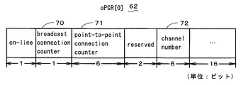
次に、図3及び図4を参照して、上記図2中におけるoPCR[0]62とiPCR[0]65の内容について説明する。oPCR[0]62は、図3に示されるように、ブロードキャスト接続でデータの送信を行う場合に1となるbroadcast connection counter70、ポイント・ツー・ポイント接続でデータの送信を行う場合に加算されるpoint-to-point connection counter71、データの送信に使用するバス9上のチャンネル番号を格納するchannel number72等より構成される。また、iPCR[0]65は、図4に示されるように、ブロードキャスト接続でデータの受信を行う場合に1となるbroadcast connection counter73、ポイント・ツー・ポイント接続でデータの受信を行う場合に加算されるpoint-to-point connection counter74、データの受信に使用するバス9上のチャンネル番号を格納するchannel number75等より構成される。 Next, the contents of oPCR [0] 62 and iPCR [0] 65 in FIG. 2 will be described with reference to FIGS. As shown in FIG. 3, the oPCR [0] 62 is a
次に、図5を参照して、図2中におけるTOPOLOGY_MAP58に格納されている情報の内容について説明する。TOPOLOGY_MAP58は、バス9上におけるノード数の情報であるnode_count76、TOPOLOGY_MAP58内に格納されているセルフIDパケットの数の情報であるself_id_count77、及び各ノードのセルフIDパケット(self_id_packet[0]〜self_id_packet[self_id_count-1])からなるセルフIDパケットテーブル78等から構成されている。 Next, the contents of the information stored in
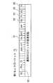
次に、図6を参照して、図5中におけるセルフIDパケットテーブル78に含まれる3種類のセルフIDパケットの内容について説明する。第1の種類のセルフIDパケット(以下、第1セルフIDパケットという)79は、図6に示されるように、該当のパケットを送出したノード(以下、送出元ノードという)の物理IDを示すPhy_ID80、送出元ノードの物理層レベルにおける最高転送速度の情報であるsp81、p0〜p2の各ポートの状態を示すp0情報82〜p2情報84、同じ物理IDを有するパケットが後に続いているか否かを示す追加パケット有無情報m85等を格納している。p0情報82〜p2情報84が“11”のときは、「該当のノードが動作中で子ポートに接続されている」ことを示し、“10”のときは、「該当のノードが動作中で親ポートに接続されている」ことを示す。また、“01”のときは、「該当のノードが動作していない」ことを示し、“00”のときは、「該当のポートが存在しない」ことを示す。 Next, the contents of the three types of self ID packets included in the self ID packet table 78 in FIG. 5 will be described with reference to FIG. As shown in FIG. 6, a first type self ID packet (hereinafter referred to as a first self ID packet) 79 is a
図5中におけるセルフIDパケットテーブル78に含まれるセルフIDパケットには、上記の第1セルフIDパケット79以外に、2つの種類のセルフIDパケットがあるが、これらのパケットのフォーマットについては、特開2000−282580等に開示されており、既知であるので、ここでは詳述しない。 The self ID packet included in the self ID packet table 78 in FIG. 5 includes two types of self ID packets in addition to the first self ID packet 79 described above. 2000-282580 and the like, which are known and will not be described in detail here.
次に、図7のフローチャートを参照して、本発明の中心となる接続変更候補一覧画面の表示処理の概略について説明する。ユーザが、ディジタルテレビ(以下、DTVと記す)から、HDDレコーダの再生映像を視聴しようとしたときに(S1)、バス9上の帯域が既に他の論理的接続(例えば、チューナとDTVとの論理的接続)に使用されているために不足し、DTVが、新たな論理的接続に必要な帯域を取得できず、HDDレコーダからの再生映像を受信することができなかったとする(S2)。この場合に、ユーザは、DTVに対して、どの接続機器間の物理的な接続を変更すればネットワーク全体の帯域使用量を削減することができるかを示した、接続変更の候補の一覧画面である接続変更候補一覧画面90(図8参照)を表示するための指示操作を行って、DTVのディスプレイ上に接続変更候補一覧画面90を表示し(S3)、どの接続機器間の物理的な接続を変更すればネットワーク全体の帯域使用量を削減することができるかを調べる(S4)。そして、ユーザは、接続変更候補一覧画面90に表示された接続変更候補から、現実的に無理のない(バスケーブルの配線上無理のない)接続変更を選んで、バスケーブルをつなぎ変え、接続機器間の物理的な接続を変更する。これにより、ネットワーク1全体の帯域使用量を削減して、バス9上における接続機器間の既存の論理的な接続を変更することなく、DTVとHDDレコーダとの間の新たな論理的接続に必要な帯域を取得できるようになるので、DTVがHDDレコーダからの再生映像を受信することができるようになる。従って、ユーザが、DTVから、HDDレコーダの再生映像を視聴することができるようになる(S5)。 Next, with reference to the flowchart of FIG. 7, the outline of the display process of the connection change candidate list screen used as the center of this invention is demonstrated. When the user tries to view the playback video of the HDD recorder from a digital television (hereinafter referred to as DTV) (S1), the bandwidth on the bus 9 is already set to another logical connection (for example, between the tuner and the DTV). It is assumed that the DTV cannot obtain a band necessary for a new logical connection and cannot receive a playback video from the HDD recorder (S2). In this case, the user can display a connection change candidate list screen indicating which connection device between the DTVs can be changed to reduce the bandwidth usage of the entire network. An instruction operation for displaying a certain connection change candidate list screen 90 (see FIG. 8) is performed, and the connection change candidate list screen 90 is displayed on the display of the DTV (S3). It is examined whether the bandwidth usage of the entire network can be reduced by changing (S4). Then, the user selects a connection change that is practically impossible (no problem in the wiring of the bus cable) from the connection change candidates displayed on the connection change candidate list screen 90, reconnects the bus cable, and connects the connected device. Change the physical connection between. This reduces the bandwidth usage of the
次に、図8及び図10に加えて、図9のフローチャートを参照して、上記の接続変更候補一覧画面を用いたネットワーク1全体の帯域使用量の削減処理について具体的に説明する。DTV2とHDDレコーダ3とチューナ4とが、図10に示されるような物理的接続であり、DTV2とHDDレコーダ3との間に既に論理的接続aが確立されているときに、ユーザが、チューナ4からHDDレコーダ3への映像の録画を行おうとしたとする(S11)。この場合に、バス9上の帯域が既に他の論理的接続aに使用されているために不足し、HDDレコーダ3が、新たな論理的接続bに必要な帯域を取得できず、チューナ4からの映像を受信することができなかったとする(S12)。このとき、ユーザは、DTV2に対して、上記の接続変更候補一覧画面90(図8参照)を表示するための指示操作を行って、DTV2のディスプレイ上に接続変更候補一覧画面90を表示し(S13)、どの接続機器間の物理的な接続を変更すればネットワーク全体の帯域使用量を削減することができるかを調べる。そして、ユーザは、接続変更候補一覧画面90に表示された接続変更候補から、現実的に無理のない(バスケーブルの配線上無理のない)接続変更を選んで(S14)、バスケーブルをつなぎ変え、接続機器間の物理的な接続を変更する。具体的には、ユーザは、図8に示される候補(1)を選んで、P社のP−XXXというモデル名で表されるDTV2と、G社のG−XXXというモデル名で表されるチューナ4との物理的接続Aを切断して、P社のP−XXXというモデル名で表されるDTV2と、T社のT−XXXというモデル名で表されるHDDレコーダ3とを物理的に接続する(図10中の物理的接続Cを行う)。これにより、ネットワーク1全体の帯域使用量を削減して、チューナ4とHDDレコーダ3との間の新たな論理的接続bに必要な帯域を取得できるようになるので、HDDレコーダ3がチューナ4からの再生映像を受信することができるようになる。従って、ユーザが、チューナ4からHDDレコーダ3への映像の録画を行うことができるようになる(S15)。 Next, referring to the flowchart of FIG. 9 in addition to FIG. 8 and FIG. 10, the bandwidth usage reduction process of the
次に、図11のフローチャートを参照して、上記の接続変更候補一覧画面90の表示処理の詳細について説明する。以下の説明では、図1におけるバスマネージャー10が、アイソクロナスリソースマネージャでもある場合の例について説明する。ユーザが、バスマネージャー10(例えば、上記のDTV2)に対して、上記の接続変更候補一覧画面90(図8参照)を表示するための指示操作を行うと、バスマネージャー10のCPU11は、TOPOLOGY_MAP58内の情報(第1セルフIDパケット79に含まれるp0情報82〜p2情報84等)に基いて、バス9上のどの接続機器間が物理的に接続されていて、どの接続機器間が物理的に接続されていないかを判定する(S21)。次に、バスマネージャー10のCPU11は、バス9上における各接続機器間の全ての論理的接続を検出する。具体的には、バスマネージャー10のCPU11は、自機のレジスタ空間15内のチャンネル管理用のレジスタであるCHANNELS_AVAILABLE HI53とCHANNELS_AVAILABLE LO54(図2参照)をチェックして、その時点で使用されているバス9上のチャンネルを検出すると共に、検出した各チャンネルを使用している送信側の接続機器と受信側の接続機器とを調べるために、バス9上の他の接続機器20、30のレジスタ空間15内のoPCR56とiPCR57の内容を読み込んで、バス9上における各接続機器間の論理的接続を検出する(S22)。 Next, the details of the display processing of the connection change candidate list screen 90 will be described with reference to the flowchart of FIG. In the following description, an example in which the
次に、バスマネージャー10のCPU11は、上記S21の判定処理において物理的に接続されていると判定された接続機器間の物理的接続を切断して、その代わりに、物理的に接続されていないと判定された接続機器間を新たに物理的に接続した場合(以下、「接続機器間の物理的な接続を変更した場合」という)に、上記S22の検出処理において検出された全ての論理的接続のうちのある論理的接続についての帯域使用量を削減可能か否かを判定する(S23)。この結果、ある論理的接続についての帯域使用量を削減可能であれば(S24でYES)、バスマネージャー10のCPU11は、該当の接続機器間の物理的な接続変更によって、バス9上の全ての論理的接続についての帯域使用量の合計である、ネットワーク1全体の帯域使用量を、該当の接続機器間の物理的な接続を変更する前よりも削減可能か否かを判定する(S25)。この結果、ネットワーク1全体の帯域使用量を削減可能であれば(S26でYES)、バスマネージャー10のCPU11は、該当の接続機器間の物理的な接続の変更の情報を、帯域使用量が小さい順になるように接続変更候補ファイル14に格納する(S27)。バスマネージャー10のCPU11は、上記S22の検出処理において検出された全ての論理的接続について、上記S23乃至S27の処理を行う。そして、バスマネージャー10のCPU11は、全ての論理的接続についての処理が終了すると(S28)、接続変更候補ファイル14に格納された、接続機器間の物理的な接続の変更の情報を、ディスプレイ23上の接続変更候補一覧画面90に接続変更の候補として一覧表示する(S29)。接続変更候補一覧画面90における接続変更の候補は、帯域使用量が小さい順に表示される。 Next, the CPU 11 of the
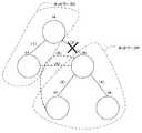
バスマネージャー10のCPU11は、上記S25の判定処理において、例え、ある接続機器間の物理的な接続変更によって、ネットワーク1全体の帯域使用量を削減可能であっても、いわゆる「ループ」になってしまうような接続変更については、接続変更候補一覧画面90上に接続変更の候補として表示しない。この場合の「ループ」になってしまうような接続変更とは、例えば、図12中の(2)で示される物理的接続を切断して、(5)で示されるように、接続機器96と接続機器97とを新たに接続することをいう。図12に示されるように、(2)の物理的接続を切断する場合には、この切断によって分断されてしまうネットワークEとネットワークFとを再度結ぶような新たな接続(例えば、(6)のような接続)を行う必要がある。 The CPU 11 of the
上述したように、本実施形態のバスマネージャー10によれば、バス9上の接続機器間の物理的接続を変更することによって、全ての論理的接続についての帯域使用量の合計である、ネットワーク1全体の帯域使用量を、接続機器間の物理的な接続を変更する前よりも削減可能か否かが判定され、この判定の結果、ネットワーク1全体の帯域使用量を削減可能と判定された、接続機器間の物理的な接続の変更の情報が、接続変更の候補としてバスマネージャー10のディスプレイ23上に一覧表示される。これにより、バス9上のある接続機器が、他の接続機器との間でアイソクロナスデータの送受信を行うために、新たな論理的接続を確立しようとしたときに、バス9上の帯域が既に他の論理的接続に使用されているために不足し、新たな論理的接続に必要な帯域を取得できない場合でも、ユーザが、上記のディスプレイ23上に一覧表示された接続変更の候補を参照することにより、新たな論理的接続に必要な帯域を確保するための接続機器間の物理的な接続の変更を容易に行うことができる。 As described above, according to the
なお、本発明は、上記実施形態に限られるものではなく、様々な変形が可能である。例えば、上記実施形態では、本発明に係るIEEEシリアルバスへの接続機器が、バスマネージャーであり、このバスマネージャーに対して、上記の接続変更候補一覧画面を表示するための指示操作を行う場合の例を示したが、本発明に係るIEEEシリアルバスへの接続機器は、必ずしもバスマネージャーである必要はない。 The present invention is not limited to the above embodiment, and various modifications can be made. For example, in the above-described embodiment, the device connected to the IEEE serial bus according to the present invention is a bus manager, and the bus manager performs an instruction operation for displaying the above connection change candidate list screen. Although an example has been shown, the device connected to the IEEE serial bus according to the present invention does not necessarily have to be a bus manager.
1 ネットワーク
10 バスマネージャー(IEEEシリアルバスへの接続機器)
11 CPU(物理的接続判定手段、論理的接続検出手段、第1の削減判定手段、第2の削減判定手段、削減判定手段)
12 メモリ(格納手段)
13 接続変更候補一覧表示PG(物理的接続判定手段、論理的接続検出手段、第1の削減判定手段、第2の削減判定手段、削減判定手段)
16 LINK(データ送受信手段)
17 PHY(データ送受信手段)
18 入力ポート(データ送受信手段)
19 出力ポート(データ送受信手段)
23 ディスプレイ(表示手段)
90 接続変更候補一覧画面1
11 CPU (physical connection determination means, logical connection detection means, first reduction determination means, second reduction determination means, reduction determination means)
12 Memory (storage means)
13 Connection change candidate list display PG (physical connection determination means, logical connection detection means, first reduction determination means, second reduction determination means, reduction determination means)
16 LINK (data transmission / reception means)
17 PHY (data transmission / reception means)
18 Input port (data transmission / reception means)
19 Output port (data transmission / reception means)
23 Display (display means)
90 Connection change candidate list screen
Claims (3)
Translated fromJapanese前記バス上における各接続機器間の接続状態に関する情報であるトポロジーマップ内の情報に基いて、どの接続機器間が物理的に接続されていて、どの接続機器間が物理的に接続されていないかを判定する物理的接続判定手段とを備えたIEEEシリアルバスへの接続機器において、
前記バス上における各接続機器間の全ての論理的な接続を検出する論理的接続検出手段と、
前記物理的接続判定手段により物理的に接続されていると判定された接続機器間の物理的な接続を切断して、その代わりに、前記物理的接続判定手段により物理的に接続されていないと判定された接続機器間を新たに物理的に接続した場合(以下、「接続機器間の物理的な接続を変更した場合」という)に、前記論理的接続検出手段により検出された全ての論理的な接続のうちのある論理的な接続についての帯域使用量を削減可能か否かを判定する第1の削減判定手段と、
前記第1の削減判定手段によってある論理的な接続についての帯域使用量を削減可能と判定されたときに、前記接続機器間の物理的な接続を変更した場合、全ての論理的な接続についての帯域使用量の合計である、ネットワーク全体の帯域使用量を、前記接続機器間の物理的な接続を変更する前よりも削減可能か否かを判定する第2の削減判定手段と、
前記第2の削減判定手段による判定の結果、ネットワーク全体の帯域使用量を削減可能と判定された、前記接続機器間の物理的な接続の変更の情報を、帯域使用量が小さい順になるように格納する格納手段と、
前記格納手段に格納された、前記接続機器間の物理的な接続の変更の情報を、接続変更の候補として一覧表示する表示手段とをさらに備えたことを特徴とするIEEEシリアルバスへの接続機器。Data transmitting / receiving means for transmitting / receiving data to / from other connected devices on the IEEE 1394 serial bus;
Based on the information in the topology map, which is information on the connection status between each connected device on the bus, which connected devices are physically connected and which connected devices are not physically connected A device for connecting to an IEEE serial bus comprising physical connection determination means for determining
Logical connection detection means for detecting all logical connections between the connected devices on the bus;
Disconnect the physical connection between the connected devices that are determined to be physically connected by the physical connection determination means, and instead of being physically connected by the physical connection determination means When the determined connection devices are newly physically connected (hereinafter referred to as “when the physical connection between the connection devices is changed”), all logical connections detected by the logical connection detection unit are detected. First reduction determination means for determining whether or not it is possible to reduce the bandwidth usage for a certain logical connection among the simple connections;
When it is determined by the first reduction determination means that the bandwidth usage for a certain logical connection can be reduced, if the physical connection between the connected devices is changed, all the logical connections Second reduction determination means for determining whether or not the bandwidth usage of the entire network, which is the total bandwidth usage, can be reduced as compared to before changing the physical connection between the connected devices;
As a result of the determination by the second reduction determination means, the information on the change in the physical connection between the connected devices that has been determined to be able to reduce the bandwidth usage of the entire network is arranged in ascending order of the bandwidth usage. Storage means for storing;
A device connected to the IEEE serial bus, further comprising display means for displaying a list of physical connection change information stored in the storage means as connection change candidates. .
前記バス上における各接続機器間の全ての論理的な接続を検出する論理的接続検出手段と、
前記バス上における各接続機器間の物理的な接続を変更した場合に、全ての論理的な接続についての帯域使用量の合計である、ネットワーク全体の帯域使用量を、前記接続機器間の物理的な接続を変更する前よりも削減可能か否かを判定する削減判定手段とをさらに備え、
前記削減判定手段による判定の結果、ネットワーク全体の帯域使用量を削減可能と判定された、前記接続機器間の物理的な接続の変更の情報を、接続変更の候補として表示手段に一覧表示するようにしたことを特徴とするIEEEシリアルバスへの接続機器。In a device connected to an IEEE serial bus having data transmission / reception means for transmitting / receiving data to / from other connected devices on the IEEE 1394 serial bus,
Logical connection detection means for detecting all logical connections between the connected devices on the bus;
When the physical connection between each connected device on the bus is changed, the bandwidth usage of the entire network, which is the sum of the bandwidth usage for all logical connections, is calculated as the physical amount between the connected devices. Further comprising a reduction determination means for determining whether or not the reduction can be made compared to before changing the connection,
As a result of the determination by the reduction determination unit, information on physical connection change between the connected devices determined to be able to reduce the bandwidth usage of the entire network is displayed on the display unit as a list of connection change candidates. A device connected to an IEEE serial bus, characterized in that
前記削減判定手段は、
前記物理的接続判定手段により物理的に接続されていると判定された接続機器間の物理的な接続を切断して、その代わりに、前記物理的接続判定手段により物理的に接続されていないと判定された接続機器間を新たに物理的に接続した場合(以下、「接続機器間の物理的な接続を変更した場合」という)に、前記論理的接続検出手段により検出された全ての論理的な接続のうちのある論理的な接続についての帯域使用量を削減可能か否かを判定する第1の削減判定手段と、
前記第1の削減判定手段によってある論理的な接続についての帯域使用量を削減可能と判定されたときに、前記接続機器間の物理的な接続を変更した場合、全ての論理的な接続についての帯域使用量の合計である、ネットワーク全体の帯域使用量を、前記接続機器間の物理的な接続を変更する前よりも削減可能か否かを判定する第2の削減判定手段とを含むことを特徴とする請求項2に記載のIEEEシリアルバスへの接続機器。Based on the information in the topology map, which is information on the connection status between each connected device on the bus, which connected devices are physically connected and which connected devices are not physically connected Further comprising physical connection determination means for determining
The reduction determination means includes
Disconnect the physical connection between the connected devices that are determined to be physically connected by the physical connection determination means, and instead of being physically connected by the physical connection determination means When the determined connection devices are newly physically connected (hereinafter referred to as “when the physical connection between the connection devices is changed”), all logical connections detected by the logical connection detection unit are detected. First reduction determination means for determining whether or not it is possible to reduce the bandwidth usage for a certain logical connection among the simple connections;
When it is determined by the first reduction determination means that the bandwidth usage for a certain logical connection can be reduced, if the physical connection between the connected devices is changed, all the logical connections Second reduction determination means for determining whether or not the bandwidth usage of the entire network, which is the sum of the bandwidth usage, can be reduced as compared to before changing the physical connection between the connected devices. The apparatus for connecting to an IEEE serial bus according to claim 2, characterized in that:
Priority Applications (2)
| Application Number | Priority Date | Filing Date | Title |
|---|---|---|---|
| JP2006149656AJP2007324681A (en) | 2006-05-30 | 2006-05-30 | Devices connected to the IEEE serial bus |
| US11/755,447US7903686B2 (en) | 2006-05-30 | 2007-05-30 | Connected device to be connected to an IEEE 1394 serial bus |
Applications Claiming Priority (1)
| Application Number | Priority Date | Filing Date | Title |
|---|---|---|---|
| JP2006149656AJP2007324681A (en) | 2006-05-30 | 2006-05-30 | Devices connected to the IEEE serial bus |
Publications (1)
| Publication Number | Publication Date |
|---|---|
| JP2007324681Atrue JP2007324681A (en) | 2007-12-13 |
Family
ID=38790010
Family Applications (1)
| Application Number | Title | Priority Date | Filing Date |
|---|---|---|---|
| JP2006149656AWithdrawnJP2007324681A (en) | 2006-05-30 | 2006-05-30 | Devices connected to the IEEE serial bus |
Country Status (2)
| Country | Link |
|---|---|
| US (1) | US7903686B2 (en) |
| JP (1) | JP2007324681A (en) |
Families Citing this family (3)
| Publication number | Priority date | Publication date | Assignee | Title |
|---|---|---|---|---|
| JP4336536B2 (en)* | 2003-07-18 | 2009-09-30 | パイオニア株式会社 | Transmission speed setting device, transmission speed setting method, information transmission system, transmission speed setting program, and information recording medium |
| GB2438017A (en) | 2006-05-02 | 2007-11-14 | Skype Ltd | Controlling communication quality by generating instructions providing a remedy to users to improve communication quality |
| GB0718980D0 (en)* | 2007-09-27 | 2007-11-07 | Skype Ltd | User interface |
Family Cites Families (15)
| Publication number | Priority date | Publication date | Assignee | Title |
|---|---|---|---|---|
| US5504757A (en)* | 1994-09-27 | 1996-04-02 | International Business Machines Corporation | Method for selecting transmission speeds for transmitting data packets over a serial bus |
| US6233637B1 (en)* | 1996-03-07 | 2001-05-15 | Sony Corporation | Isochronous data pipe for managing and manipulating a high-speed stream of isochronous data flowing between an application and a bus structure |
| JP2001503930A (en) | 1996-06-21 | 2001-03-21 | ソニー エレクトロニクス インク | Device user interface with topology map |
| JP2000013423A (en) | 1998-06-26 | 2000-01-14 | Sony Corp | Information processing apparatus and method, and providing medium |
| JP3436174B2 (en)* | 1999-03-09 | 2003-08-11 | 日本電気株式会社 | Communication method |
| US6986156B1 (en)* | 1999-06-11 | 2006-01-10 | Scientific Atlanta, Inc | Systems and methods for adaptive scheduling and dynamic bandwidth resource allocation management in a digital broadband delivery system |
| US6728821B1 (en)* | 1999-11-29 | 2004-04-27 | Sony Corporation | Method and system for adjusting isochronous bandwidths on a bus |
| AU2001260560A1 (en)* | 2000-05-18 | 2001-11-26 | Firemedia Communications (Israel) Ltd. | Bandwidth and path allocation method for a switched fabric connecting multiple multimedia buses |
| US7542474B2 (en)* | 2001-02-26 | 2009-06-02 | Sony Corporation | Method of and apparatus for providing isochronous services over switched ethernet including a home network wall plate having a combined IEEE 1394 and ethernet modified hub |
| JP2002305527A (en) | 2001-04-06 | 2002-10-18 | Toshiba Corp | Device connection status display device and method of displaying device connection status in the device |
| EP1263172A3 (en)* | 2001-05-29 | 2002-12-18 | Thomson Licensing S.A. | Method for managing resources of a link in a communication network |
| KR100456636B1 (en)* | 2002-11-25 | 2004-11-10 | 한국전자통신연구원 | Architecture of look-up service in jini-based home network supporting ieee 1394 and tcp/ip and method thereof |
| US7315985B1 (en)* | 2002-12-31 | 2008-01-01 | Emc Corporation | Methods and apparatus for managing network resources using a network topology view |
| US7158536B2 (en)* | 2004-01-28 | 2007-01-02 | Rambus Inc. | Adaptive-allocation of I/O bandwidth using a configurable interconnect topology |
| KR100617831B1 (en)* | 2005-02-18 | 2006-08-28 | 삼성전자주식회사 | IIEE 1394 Automatic channel selection method for receiving streams transmitted over a network |
- 2006
- 2006-05-30JPJP2006149656Apatent/JP2007324681A/ennot_activeWithdrawn
- 2007
- 2007-05-30USUS11/755,447patent/US7903686B2/ennot_activeExpired - Fee Related
Also Published As
| Publication number | Publication date |
|---|---|
| US20070280139A1 (en) | 2007-12-06 |
| US7903686B2 (en) | 2011-03-08 |
Similar Documents
| Publication | Publication Date | Title |
|---|---|---|
| US9413697B2 (en) | All delivered network adaptor | |
| US20080288638A1 (en) | Method and system for managing network resources in audio/video bridging enabled networks | |
| US6721818B1 (en) | Electronic device that stores information on its location based on information obtained from a node | |
| TW545014B (en) | Network bus bridge and system | |
| KR101394796B1 (en) | Message passing framework for audio/video streaming in a topology of devices | |
| RU2325765C2 (en) | Determining and configuring data transmission path in network | |
| US6122248A (en) | Data transmission system with bus failure recovery | |
| US20070208848A1 (en) | Device connection routing for controller | |
| Kunzman et al. | 1394 high performance serial bus: The digital interface for ATV | |
| KR100795257B1 (en) | Network error display device and error detection display method | |
| KR20010090768A (en) | Electronic equipment, and method for processing digital serial data at bus initialization phase in interface unit | |
| JP2007324681A (en) | Devices connected to the IEEE serial bus | |
| KR20050015534A (en) | IEEE 1394 Based Unidirectional Ring System for Indoor Backbone Network | |
| EP1472832A2 (en) | Method and device for managing a connection and resource reservation in a communication network comprising a bridge | |
| KR101337559B1 (en) | Virtualization support programmable platform and Method for transferring packet | |
| KR20000007567A (en) | Bus reset treatment method on the network connected to ieee 1394 | |
| JP4683120B2 (en) | Electronic device and communication method | |
| US7421507B2 (en) | Transmission of AV/C transactions over multiple transports method and apparatus | |
| JP2000151614A (en) | Device and method for communicating digital information | |
| US7042896B1 (en) | Method for managing a digital interface connection | |
| JP5618805B2 (en) | COMMUNICATION DEVICE, NETWORK SYSTEM, AND COMMUNICATION METHOD | |
| JP4060761B2 (en) | Optical transmission device and electronic device including the same | |
| KR100336876B1 (en) | A Real-Time Data Communication Device | |
| JPH11163866A (en) | Connection status transmission device, connection status display data creation device, and connection status display method | |
| JPH11163865A (en) | Connection status transmission device, connection status display data creation device, and connection status display method |
Legal Events
| Date | Code | Title | Description |
|---|---|---|---|
| A300 | Application deemed to be withdrawn because no request for examination was validly filed | Free format text:JAPANESE INTERMEDIATE CODE: A300 Effective date:20090804 |