JP2007322361A - Probe for nuclear magnetic resonance apparatus and nuclear magnetic resonance apparatus - Google Patents
Probe for nuclear magnetic resonance apparatus and nuclear magnetic resonance apparatusDownload PDFInfo
- Publication number
- JP2007322361A JP2007322361AJP2006155971AJP2006155971AJP2007322361AJP 2007322361 AJP2007322361 AJP 2007322361AJP 2006155971 AJP2006155971 AJP 2006155971AJP 2006155971 AJP2006155971 AJP 2006155971AJP 2007322361 AJP2007322361 AJP 2007322361A
- Authority
- JP
- Japan
- Prior art keywords
- coil
- probe
- nuclear magnetic
- magnetic resonance
- reception
- Prior art date
- Legal status (The legal status is an assumption and is not a legal conclusion. Google has not performed a legal analysis and makes no representation as to the accuracy of the status listed.)
- Pending
Links
Images


Classifications
- G—PHYSICS
- G01—MEASURING; TESTING
- G01R—MEASURING ELECTRIC VARIABLES; MEASURING MAGNETIC VARIABLES
- G01R33/00—Arrangements or instruments for measuring magnetic variables
- G01R33/20—Arrangements or instruments for measuring magnetic variables involving magnetic resonance
- G01R33/28—Details of apparatus provided for in groups G01R33/44 - G01R33/64
- G01R33/32—Excitation or detection systems, e.g. using radio frequency signals
- G01R33/36—Electrical details, e.g. matching or coupling of the coil to the receiver
- G01R33/3642—Mutual coupling or decoupling of multiple coils, e.g. decoupling of a receive coil from a transmission coil, or intentional coupling of RF coils, e.g. for RF magnetic field amplification
- G01R33/3657—Decoupling of multiple RF coils wherein the multiple RF coils do not have the same function in MR, e.g. decoupling of a transmission coil from a receive coil
- G—PHYSICS
- G01—MEASURING; TESTING
- G01R—MEASURING ELECTRIC VARIABLES; MEASURING MAGNETIC VARIABLES
- G01R33/00—Arrangements or instruments for measuring magnetic variables
- G01R33/20—Arrangements or instruments for measuring magnetic variables involving magnetic resonance
- G01R33/28—Details of apparatus provided for in groups G01R33/44 - G01R33/64
- G01R33/32—Excitation or detection systems, e.g. using radio frequency signals
- G01R33/34—Constructional details, e.g. resonators, specially adapted to MR
- G01R33/34046—Volume type coils, e.g. bird-cage coils; Quadrature bird-cage coils; Circularly polarised coils
- G01R33/34053—Solenoid coils; Toroidal coils
- G—PHYSICS
- G01—MEASURING; TESTING
- G01R—MEASURING ELECTRIC VARIABLES; MEASURING MAGNETIC VARIABLES
- G01R33/00—Arrangements or instruments for measuring magnetic variables
- G01R33/20—Arrangements or instruments for measuring magnetic variables involving magnetic resonance
- G01R33/28—Details of apparatus provided for in groups G01R33/44 - G01R33/64
- G01R33/32—Excitation or detection systems, e.g. using radio frequency signals
- G01R33/34—Constructional details, e.g. resonators, specially adapted to MR
- G01R33/34046—Volume type coils, e.g. bird-cage coils; Quadrature bird-cage coils; Circularly polarised coils
- G01R33/34069—Saddle coils
- G—PHYSICS
- G01—MEASURING; TESTING
- G01R—MEASURING ELECTRIC VARIABLES; MEASURING MAGNETIC VARIABLES
- G01R33/00—Arrangements or instruments for measuring magnetic variables
- G01R33/20—Arrangements or instruments for measuring magnetic variables involving magnetic resonance
- G01R33/28—Details of apparatus provided for in groups G01R33/44 - G01R33/64
- G01R33/32—Excitation or detection systems, e.g. using radio frequency signals
- G01R33/34—Constructional details, e.g. resonators, specially adapted to MR
- G01R33/34015—Temperature-controlled RF coils
- G01R33/34023—Superconducting RF coils
Landscapes
- Physics & Mathematics (AREA)
- Condensed Matter Physics & Semiconductors (AREA)
- General Physics & Mathematics (AREA)
- Magnetic Resonance Imaging Apparatus (AREA)
Abstract
Translated fromJapaneseDescription
Translated fromJapanese本発明は、核磁気共鳴装置に使用されるプローブと、そのプローブを備えた核磁気共鳴装置に関する。 The present invention relates to a probe used in a nuclear magnetic resonance apparatus and a nuclear magnetic resonance apparatus including the probe.
核磁気共鳴(NMR)装置は、マグネットによって形成される静磁場空間に設置された試料に高周波電磁波を照射し、試料が放出する核磁気共鳴信号を検出する分析装置であり、有機物の分子構造の解析などに好適とされている。この核磁気共鳴装置において、プローブコイルは試料に高周波磁場を照射する役割と、試料が放出する信号を検出する役割を併せ持つ。照射は送信コイルにより行い、検出は受信コイルにより行なう。両者は1つのコイルで兼用させるようにしても良いし、別々のコイルで行なうようにしてもよい。いずれにしても、照射の際には、送信コイルが発生する磁場が試料の領域で均一であることが望ましく、検出の際には、受信コイルが効率よく信号を検出できることが望ましい。 A nuclear magnetic resonance (NMR) device is an analyzer that irradiates a sample placed in a static magnetic field space formed by a magnet with high-frequency electromagnetic waves and detects a nuclear magnetic resonance signal emitted from the sample, and has a molecular structure of organic matter. It is suitable for analysis and the like. In this nuclear magnetic resonance apparatus, the probe coil has both the role of irradiating the sample with a high-frequency magnetic field and the role of detecting the signal emitted by the sample. Irradiation is performed by a transmitting coil, and detection is performed by a receiving coil. Both may be shared by one coil, or may be performed by separate coils. In any case, it is desirable that the magnetic field generated by the transmission coil is uniform in the region of the sample during irradiation, and it is desirable that the reception coil can efficiently detect the signal during detection.
送受兼用の1つのコイルとした場合には、1つの送受用コイルに対して1つの同調整合回路が必要である。同調整合回路には、共振周波数の調整とインピーダンスのマッチングを行なうために、可変コンデンサが2つ以上配置される。コイルが一つであるため、マッチングを行なう回路は1組でよいが、受信機と送信機への接続を切り替える切替回路が別途必要である。特許文献1には、このような切替回路を用いて、送信と受信を1つのコイルで行なう方法が記載されている。 When one coil is used for both transmission and reception, one tuning matching circuit is required for one transmission / reception coil. Two or more variable capacitors are arranged in the tuning matching circuit in order to adjust the resonance frequency and match the impedance. Since there is one coil, only one set of matching circuits is required, but a separate switching circuit for switching the connection between the receiver and the transmitter is necessary. Patent Document 1 describes a method of performing transmission and reception with one coil using such a switching circuit.
一方、送受(照射と検出)を別のコイルで行なう場合には、コイルは受信コイルと送信コイルの2つなので、マッチングを行なう同調整合回路は2組必要である。この方式では、それぞれのコイルの形を独立に最適化することができ、単一のコイルで行なう場合よりも、いろいろな面で有利となる。例えば、超電導体を用いたコイルでは抵抗が小さくなるので共振のQ(Quality−factor)値を高めることができ、感度がよくなる。しかし、送受分離式では、2つのコイルの間に起きる電磁気的な結合のために、受信コイルによる信号の検出感度が損なわれるという問題が起きる。従来は、それぞれのコイルが発生する磁場が直交するように厳密に配置したり、わずかに残る結合を試行錯誤的な相対位置の微調整をしたりすることで解決してきた。 On the other hand, when transmission / reception (irradiation and detection) are performed by different coils, two coils, that is, a reception coil and a transmission coil, and therefore two sets of tuning matching circuits for performing matching are required. In this method, the shape of each coil can be optimized independently, which is advantageous in various aspects as compared with the case of using a single coil. For example, in a coil using a superconductor, the resistance is reduced, so that the resonance Q (Quality-factor) value can be increased and the sensitivity is improved. However, in the transmission / reception separation type, there arises a problem that the detection sensitivity of the signal by the receiving coil is impaired due to electromagnetic coupling occurring between the two coils. Conventionally, they have been solved by arranging them strictly so that the magnetic fields generated by the respective coils are orthogonal to each other, or by finely adjusting the relative position by trial and error for the slight remaining coupling.
NMR装置を高感度化する方法としては、プローブコイルを冷却して感度を向上する手法がある。送受分離式のプローブコイルに、この方法を応用した場合、コイル間の結合を抑えるために従来行なわれてきた手法は適用しにくい。その理由は、プローブコイルを冷却するために、真空で断熱された容器の中に置かなければならないからである。このような環境下では、プローブコイルに外部から直接触れて微調整を行なうことは非常に難しい。また、冷却のため、熱抵抗が小さい伝熱経路を確保するという点でも微調整は期待できない。 As a method of increasing the sensitivity of the NMR apparatus, there is a method of improving the sensitivity by cooling the probe coil. When this method is applied to a transmission / reception separation type probe coil, it is difficult to apply the conventional method for suppressing the coupling between the coils. The reason is that in order to cool the probe coil, it must be placed in a vacuum insulated container. Under such circumstances, it is very difficult to perform fine adjustment by directly touching the probe coil from the outside. In addition, fine adjustment cannot be expected in terms of securing a heat transfer path with low thermal resistance for cooling.
本発明の目的は、送信コイルと受信コイルとの間に電磁気的な結合があったとしても、その影響を抑え、受信コイルが本来持つ検出効率を引き出すことができるようにしたNMR用プローブとそれを備えたNMR装置を提供することにある。 An object of the present invention is to provide an NMR probe capable of suppressing the influence of electromagnetic coupling between a transmitting coil and a receiving coil and extracting the inherent detection efficiency of the receiving coil, and the same. It is providing the NMR apparatus provided with.
本発明は、試料に高周波電磁波を照射する送信コイルと、試料が放出する核磁気共鳴信号を検出する受信コイルとを具備する核磁気共鳴装置用プローブにおいて、前記送信コイルに切替スイッチを備えたことを特徴とする。 The present invention provides a probe for a nuclear magnetic resonance apparatus including a transmission coil that irradiates a sample with high-frequency electromagnetic waves and a reception coil that detects a nuclear magnetic resonance signal emitted from the sample. It is characterized by.
送受分離式プローブの送信コイルに切替スイッチを配置したことで、照射時と検出時で送信回路の共振状態を切り替えることができ、送受間の電磁気的な結合が残っていたとしても受信コイルの感度の低下を抑えることができる。 By arranging a switch on the transmitter / receiver probe's transmitter coil, the resonance state of the transmitter circuit can be switched between irradiation and detection, and the sensitivity of the receiver coil even if electromagnetic coupling between transmitter and receiver remains. Can be suppressed.
切替スイッチには、超電導体又は半導体素子を用いることができるし、また、それは非常に好ましい。切替スイッチは送信コイルと直列または並列に挿入することができる。直列に挿入する場合には、切替スイッチが照射時に入、受信時に切と動作するようにする。また、並列に挿入する場合には、切替スイッチが照射時に切、受信時に入と動作するようにする。 A superconductor or a semiconductor element can be used for the changeover switch, and it is very preferable. The changeover switch can be inserted in series or in parallel with the transmission coil. When inserted in series, the changeover switch is turned on during irradiation and turned off during reception. In addition, when inserting in parallel, the changeover switch is turned off at the time of irradiation and turned on at the time of reception.
超電導体を用いた切替スイッチは、臨界電流を閾値として送受の状態に応じ受動的に切り替わるもの、或いは、ヒータ加熱による温度上昇により能動的に切り替わるものが望ましい。更に、ヒータ加熱の制御電流は平常時と送信時に入であり、受信時と受信切り替え動作時のみ切と動作し、平常時と送信時に切替スイッチを入、受信時に切替スイッチを切と動作させることが望ましい。 The changeover switch using a superconductor is preferably one that switches passively according to the state of transmission / reception with a critical current as a threshold, or one that switches actively due to a temperature rise due to heater heating. Furthermore, the heater heating control current is on during normal times and during transmission, operates only during reception and during reception switching operations, and is switched on during normal times and during transmission, and is switched off during reception. Is desirable.
本発明は、マグネットによって形成される静磁場空間に設置された試料に送受分離式プローブのコイルから高周波電磁波を照射し、試料が放出する核磁気共鳴信号を検出する核磁気共鳴装置において、前記プローブが試料に高周波電磁波を照射する送信コイルと、試料が放出する核磁気共鳴信号を検出する受信コイルを備え、前記送信コイルに切替スイッチを有することを特徴とする。 The present invention relates to a nuclear magnetic resonance apparatus for detecting a nuclear magnetic resonance signal emitted from a sample by irradiating a sample placed in a static magnetic field space formed by a magnet with a high frequency electromagnetic wave from a coil of a transmission / reception separation type probe. Comprises a transmission coil for irradiating the sample with high-frequency electromagnetic waves and a reception coil for detecting a nuclear magnetic resonance signal emitted from the sample, and the transmission coil has a changeover switch.
送信コイルでのエネルギーの浪費を抑えることができ、受信コイルが本来持つ検出効率を引き出して、高感度なNMR計測を達成することができる。 Energy waste in the transmission coil can be suppressed, the detection efficiency inherent in the reception coil can be extracted, and highly sensitive NMR measurement can be achieved.
以下、本発明の実施形態を、図面を用いて説明する。但し、以下の形態に限定されるものではない。 Hereinafter, embodiments of the present invention will be described with reference to the drawings. However, it is not limited to the following forms.
本発明に係るNMR用プローブの概略構成図を図1に示し、プローブコイルの拡大図を図2に示す。プローブコイルの構成は送受分離式であり、受信コイル1と送信コイル2を有する。送受分離式の場合には、送受兼用のコイルのように、受信機6と送信機7の接続を切り替える切替回路は不要である。受信コイル1は感度を最適化したコイルであり、送信コイル2は照射磁場均一性に優れたコイルであることが望ましい。受信コイルの感度を高めるためにはQ値を向上することが有効であり、コイルで発生する損失を抑えるために超電導体を用いた受信コイルがより高感度となる。金属などのコイルを冷却することでも、抵抗が減少するためQ値が改善され、感度が向上する。受信コイル1には同調整合回路4が備えられ、送信コイル2には同調整合回路3が備えられている。また、同調整合回路3,4には、共振周波数の調整とインピーダンスのマッチングを行なうために、それぞれ可変コンデンサ8が2つずつ備えられている。同調整合回路4と受信機6及び同調整合回路3と送信機7は、それぞれ、同軸ケーブル5によって接続される。なお、一般的な受信機の構成では、最前段に前置増幅器10が設置されている。 FIG. 1 shows a schematic configuration diagram of an NMR probe according to the present invention, and FIG. 2 shows an enlarged view of a probe coil. The configuration of the probe coil is a transmission / reception separation type, and has a reception coil 1 and a
プローブコイルは、感度向上のために冷却されており、プローブ容器22内は冷却のために真空に保たれている。プローブコイルを冷却すると熱雑音低減と共振のQ値向上の効果を得ることができ、感度が向上する。冷却の効果を十分得るために、プローブコイルは40K以下の温度まで冷却される。より安定して冷却するためには、独自の冷却源を持つ熱輻射シールド23や積層断熱材を真空部分に配置して、室温のプローブ容器22から低温のコイル部や回路部に輻射などによって熱が伝わるのを遮断することが望ましい。プローブコイル周辺には冷却のための熱交換器24が設置されている。 The probe coil is cooled to improve sensitivity, and the inside of the
プローブコイルは、図5に示すように受信コイル形状をソレノイド型にし、送信コイル形状をサドル型にすることが望ましく、より送受分離型の特徴を生かしたものとすることができる。 As shown in FIG. 5, it is desirable that the probe coil is a solenoid type and the transmission coil shape is a saddle type, and the probe coil can take advantage of the characteristics of the transmission / reception separation type.
ソレノイド型受信コイルは、試料の磁化との結合が比較的強く検出効率に優れている。一方、サドル型送信コイルは、照射磁場の均一性に優れている。サドル型送信コイルのコイルの高さをソレノイド型受信コイルのコイルの高さよりも高くすることで、ソレノイド型受信コイルの有効検出領域において、試料の核スピンを同じ強さで倒すことができる。このことは、有機物の測定から、複雑なタンパク質の構造解析まで、あらゆるNMR計測において利点となる。 The solenoid-type receiving coil has a relatively strong coupling with the magnetization of the sample and is excellent in detection efficiency. On the other hand, the saddle type transmission coil is excellent in the uniformity of the irradiation magnetic field. By making the height of the coil of the saddle type transmission coil higher than the height of the coil of the solenoid type reception coil, the nuclear spin of the sample can be brought down with the same strength in the effective detection region of the solenoid type reception coil. This is advantageous in every NMR measurement from measurement of organic matter to structural analysis of complex protein.
受信コイルは受信用の同調整合回路4で共振周波数とインピーダンスを整合され、雑音指数に優れた前置増幅器10に接続されている。前置増幅器10も雑音指数改善のため低温に冷却される。 The receiving coil is connected to the
送信コイルは送信用の同調整合回路3で共振周波数とインピーダンスを整合され、送信機7に接続されている。送信機7は、ラジオ波周波数のkWクラスのパワーアンプである。 The transmission coil is matched in resonance frequency and impedance with a tuning matching circuit 3 for transmission, and is connected to the
送信コイルと受信コイルは、2つのコイルの相対位置をできるだけ正確に決めるために、両者の間にスペーサ17を介して結合される。図5では、円筒状のスペーサ17の内側にソレノイド型の受信コイル1がスペーサと接して設置され、スペーサ17の外側にサドル型の送信コイル2がスペーサと接して設置されている。さらに、送信コイル2の高さは受信コイル1の高さよりも高いものとなっている。 The transmitting coil and the receiving coil are coupled via a
スペーサ17は熱交換器に接続され、コイルを冷却する熱伝導経路ともなっている。スペーサの材質は、電気絶縁性であり、且つ、コイルが冷却される低温で熱伝導のよい材料を選択することが望ましい。また、NMR信号の周波数は数十MHz〜数百MHzであるので、受信コイルのQ値を高めるためには、コイル周辺の空間の高周波損失を抑える必要があり、この周波数帯での誘電損失が小さい材料が望ましい。スペーサ材料の候補としてはサファイア(Al2O3)、窒化アルミニウム(AlN)、炭化ケイ素(SiC)、窒化ケイ素(Si3N4)などがあげられる。The
受信コイルは円筒状のボビンに巻きつけられた形態または平板状の基板に薄膜として形成された形態が考えられる。いずれの形態であっても受信効率に優れた受信コイルを実現できるので、受信コイルの形状は任意でよい。 The receiving coil may be wound around a cylindrical bobbin or formed as a thin film on a flat substrate. In any form, a receiving coil with excellent receiving efficiency can be realized, and the shape of the receiving coil may be arbitrary.
送受分離式プローブコイルでは、送信コイルと受信コイル間の電磁気的な結合が問題となる。双方のコイルがほぼ同じ周波数で共振するので、わずかな結合でもエネルギーの流れ込みが顕著に起こり、結果として受信コイルが本来持つ感度を損ねることとなる。取りうる対策の一つは、送信コイルと受信コイルの間の磁気的結合を抑えるために、それぞれのコイルに通電した際の発生磁場の方向を直行させ、鎖交磁束を極力小さくことである。しかしながら、2つのコイルの結合を完全に取り除くことは非常に難しい。なぜならば、2つのコイルの結合の度合いは冷却した動作状態でしか確認できない。例え室温で結合を取り除けたとしても、冷却すると物質は収縮するために位置関係が変わるようになり、その結果、冷却後に再度、結合が現れる。冷却状態では送信コイルと受信コイルは真空中に配置されているので、配置の微調整を行なおうとしても容易に触れることはできない。また、プローブコイルを十分安定に冷却するためには、コイルと伝熱経路であるスペーサが強固に固定されている必要がある。 In the transmission / reception separation type probe coil, electromagnetic coupling between the transmission coil and the reception coil becomes a problem. Since both coils resonate at substantially the same frequency, even a slight coupling causes a significant flow of energy, resulting in a loss of the inherent sensitivity of the receiving coil. One of the measures that can be taken is to reduce the magnetic flux linkage as much as possible by directing the direction of the magnetic field generated when each coil is energized in order to suppress the magnetic coupling between the transmitting coil and the receiving coil. However, it is very difficult to completely remove the coupling between the two coils. This is because the degree of coupling between the two coils can only be confirmed in a cooled operating state. Even if the bond can be removed at room temperature, the substance contracts when cooled, and the positional relationship changes. As a result, the bond appears again after cooling. Since the transmitting coil and the receiving coil are arranged in a vacuum in the cooled state, they cannot be easily touched even if fine adjustment of the arrangement is performed. In addition, in order to cool the probe coil sufficiently stably, the coil and the spacer as the heat transfer path need to be firmly fixed.
本発明においては、受信時に送信コイル側の共振のバランスを崩すことにより、カップリングによる感度低下の問題を解決する。このために、図1では、送信コイル2と電気的に並列に超電導ブリッジ11を挿入している。超電導ブリッジは基板13上に配置されており、コイルの引き出し線12と電気的に接続されている。この超電導ブリッジ11は、送信時には開放、受信時には短絡と切り替わることができる。超電導ブリッジによるスイッチの切り替えは、次のようにして実現する。 In the present invention, the problem of sensitivity reduction due to coupling is solved by breaking the balance of resonance on the transmission coil side during reception. For this purpose, a
NMR計測では、送信時の信号の大きさと、受信時の信号の大きさは大きく違うという特徴がある。送信時には、数W〜数十W程度の信号強度であり、受信時にはせいぜいμW程度の信号強度である。よって、この間に閾値を設けて受動的に切り替わるように超電導ブリッジの臨界電流を設定すると良い。スイッチの切り替えの閾値となるブリッジの臨界電流は1mA程度が良い。また、切時の電気抵抗は数百Ω程度になるように設定する。臨界電流及び電気抵抗の設定はブリッジの断面積と長さにより可能である。臨界電流は断面積が大きいほど大きくなる。電気抵抗は、断面積が小さく、経路が長いほど大きくなる。ブリッジの形状は極力インダクタンスを小さくするように決める。インダクタンスは幅広で短いほど小さくできる。超電導ブリッジには臨界電流密度が高い材料を用い、また扁平な断面で短い形状にすることが好ましい。例えば、厚さ0.4μm、幅0.1mm程度の二ホウ化マグネシウムの薄膜形状では、長さを10mm程度とすることで所望の臨界電流と抵抗を実現できる。また、ブリッジの形状は単純な直線状とするよりは、図3及び図4に示したように、蛇行形状などの発生磁場をキャンセルしインダクタンスを低くしたような形状がよい。図3及び図4では、往復の引き出し線12の間を単純に直線で結ぶよりも長い距離で接続しているが、蛇行している隣り同士の線で発生磁場を打ち消したことで、インダクタンスを直線で結んだときとほぼ同程度にすることができる。これにより、高周波信号においても、より低いインピーダンスでコイル両端を接続することができ、スイッチオフ時にはより高い抵抗で接続することができ、スイッチとして優れたものとなる。 The NMR measurement has a feature that the magnitude of the signal at the time of transmission is greatly different from the magnitude of the signal at the time of reception. At the time of transmission, the signal strength is about several W to several tens of W, and at the time of reception, the signal strength is about μW at most. Therefore, it is preferable to set a critical current of the superconducting bridge so that a threshold value is provided between them to switch passively. The critical current of the bridge serving as a switch switching threshold is preferably about 1 mA. In addition, the electrical resistance when turned off is set to be about several hundred Ω. The critical current and electrical resistance can be set by the cross-sectional area and length of the bridge. The critical current increases as the cross-sectional area increases. The electrical resistance increases as the cross-sectional area decreases and the path becomes longer. The shape of the bridge is determined so as to reduce the inductance as much as possible. Inductance can be made smaller as it is wider and shorter. It is preferable to use a material having a high critical current density for the superconducting bridge and to have a flat shape and a short shape. For example, in a thin film shape of magnesium diboride having a thickness of about 0.4 μm and a width of about 0.1 mm, a desired critical current and resistance can be realized by setting the length to about 10 mm. Further, the shape of the bridge is preferably a shape in which the generated magnetic field such as a meandering shape is canceled and the inductance is lowered, as shown in FIGS. 3 and 4, rather than a simple linear shape. In FIGS. 3 and 4, the
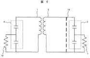
超電導ブリッジによるスイッチが開放となっている送信時の等価回路を図6に示す。スイッチは開放状態14となっているため、回路動作上は無視できる。このときには、通常の送受分離型プローブコイルとして動作する。共振回路となっている送信用回路に流れる電流が磁場を発生し、試料に高周波磁場が照射される。このとき、送信コイルと受信コイルはわずかに結合しているので、受信コイルにも電流が流れる。しかし、送信コイルのQ値は受信コイルのQ値に対して小さいので、回路の特性を損なうことは無く、送信の機能においては問題とならない。受信コイルに流れる電流が大きく、受信回路の後段に設置される前置増幅器10に大きな信号が入力され破損の可能性があるが、ダイオードなどを使用した保護回路を設置することで回避できる。 FIG. 6 shows an equivalent circuit at the time of transmission in which the switch by the superconducting bridge is open. Since the switch is in the
ブリッジによるスイッチが短絡となっている受信時の等価回路を図7に示す。このとき、受信回路は共振状態にあるが、送信コイルはコイル両端を短絡した短絡状態15であるために共振を起こさないか、もしくは目的とする信号の周波数から大きく外れた周波数で共振を起こすことになる。ブリッジがない場合は、受信時に受信回路から送信回路へ信号が流れ込むために、受信回路が本来持つ感度を損ねることとなるが、ブリッジを有する本実施例に示す形態では、送信回路側の共振が崩れるので、信号の流れ込みが大きく抑えられる。 FIG. 7 shows an equivalent circuit at the time of reception in which the switch by the bridge is short-circuited. At this time, although the receiving circuit is in a resonance state, the transmission coil is in a short-circuited
さらに詳しく説明すると、受信コイルが信号を検出すると、受信コイルの両端には電圧が誘起され、また、受信回路には電流が流れる。受信コイルには試料の回転磁化によって誘起される起電力16が生じている。受信回路は共振状態であり、インピーダンスは非常に低く、抵抗成分のみとなっている。このときに、抵抗成分に流れる電流によって消費される電力が観測される信号となる。このときの、受信コイルと送信コイルの磁気的な結合を考えると、2つのコイルは変圧器のように振る舞い、送信コイルには受信コイルに生じる電圧と結合の度合いに応じて、送信コイルに電圧が誘起される。今、送信コイルの両端は超電導ブリッジにより短絡されているので、送信回路の共振周波数が目的とする信号の核磁気共鳴周波数からずれており、検出信号の核磁気共鳴周波数に対しては非常に高いインピーダンスとして感じられる。よって、電流はほとんど流れることができず、送信回路で浪費される電力はほんのわずかとなる。よって、送信回路での浪費を抑えることで、受信コイルの本来の検出効率を引き出すことが可能となり、その結果、より高い感度が得られることとなる。 More specifically, when the receiving coil detects a signal, a voltage is induced across the receiving coil, and a current flows through the receiving circuit. An
回路シミュレーションにより1割ほどの磁気的な結合を仮定した場合のスイッチの効果を計算した。超電導ブリッジによるスイッチを配置しないときは50%ほど受信信号を損なうが、超電導ブリッジによるスイッチを配置しスイッチを入としたときは、受信信号の損失が4%程度にまで低減される。従来のスイッチが無い場合と比べると、受信感度としては約2倍程度優れたものとなる。 The effect of the switch when a magnetic coupling of about 10% was assumed by circuit simulation was calculated. When a switch using a superconducting bridge is not disposed, the received signal is impaired by about 50%. However, when a switch using a superconducting bridge is disposed and the switch is turned on, the loss of the received signal is reduced to about 4%. Compared with the case where there is no conventional switch, the reception sensitivity is about twice as good.
プローブコイルを試作し、スイッチの効果をQ値の測定により検証を行った。スイッチが切の場合には、双方が密に結合しているため、シミュレーションのように、受信コイルのマッチングを容易には取ることができず、Q値の観測まで至らなかった。一方、スイッチを入りとした場合には、送信コイルの影響が排除され、容易にマッチングを取ることができ、送信コイルがない場合のQ値から約10%程度の低減に抑えられていることがわかった。 A probe coil was prototyped and the effect of the switch was verified by measuring the Q value. When the switch is off, since both are closely coupled, the matching of the receiving coil cannot be easily performed as in the simulation, and the Q value has not been observed. On the other hand, when the switch is turned on, the influence of the transmission coil is eliminated, matching can be easily performed, and the reduction of about 10% from the Q value when there is no transmission coil is suppressed. all right.
以上の構成により、送信コイルに対して並列に超電導のブリッジを挿入することで、結合のための受信感度の低下を抑え、NMR用プローブの高感度化を得ることができた。 With the above configuration, by inserting a superconducting bridge in parallel with the transmission coil, it was possible to suppress a decrease in reception sensitivity for coupling and to increase the sensitivity of the NMR probe.
本実施例によるプローブの構成を図8に示す。実施例1の場合とはスイッチの切り替え方法が異なる。それ以外の部分は実施例1の構成と同様である。実施例1では超電導ブリッジの電流容量を決めて受動的に切り替える方式であったが、本実施例ではヒータ18により加熱することで超電導ブリッジの温度を変化させて、入切を切り替える。ヒータの発熱は、外部においた直流もしくは低周波数の電源19により制御する。臨界電流は受信に必要とされる量が十分に確保されていればよくなるが、切時の抵抗は数百Ω確保されなければならない。 The configuration of the probe according to this example is shown in FIG. The switch switching method is different from that in the first embodiment. The other parts are the same as those in the first embodiment. In the first embodiment, the current capacity of the superconducting bridge is determined and switched passively. However, in this embodiment, heating by the
入時及び切時の双方で高速に切り替えることは難しい。しかしながら、NMR計測の特徴として、送信後の受信時、つまりスイッチの動作としては入時にのみ高速の切り替えが要求される。よって、入時に高速の切り替え動作ができるようにする。これを実現するためには、受信時のみスイッチが入となるようにヒータを動作させる。スイッチを高速で切り替えるためには、熱容量が小さい方がよい。そのためには、臨界温度が20Kより小さい超電導材料をブリッジの材料として使用するのがよい。20K程度の温度以上では、物質の比熱がある程度大きくなり、温度の制御性が良くなる。超電導材料を選択する際には、環境の温度と磁場強度の双方を考慮する必要がある。スイッチは試料の近傍にあり、数T以上の強い磁場に晒される。この条件で、20K前後の臨界温度を有する超電導材料は二ホウ化マグネシウム(MgB2)、ニオブ3スズ(Nb3Sn)、ニオブ3アルミニウム(Nb3Al)などであり、これらの材料を使用するのがよい。また、スイッチを載せる基板材料は、ブリッジに用いる超電導材料の臨界温度以下で大きく熱伝導率が低下する材料がよい。これを満たす材料であれば、ヒータで加熱した際に急激に温度が上昇し、スイッチが切となり、加熱を止めた際に温度が復帰しスイッチを入とすることができる。It is difficult to switch at high speed both on and off. However, as a feature of NMR measurement, at the time of reception after transmission, that is, as a switch operation, high-speed switching is required only at the time of turning on. Therefore, a high-speed switching operation can be performed when entering. In order to realize this, the heater is operated so that the switch is turned on only during reception. In order to switch the switch at high speed, it is better that the heat capacity is small. For this purpose, it is preferable to use a superconducting material having a critical temperature lower than 20K as a material for the bridge. Above a temperature of about 20K, the specific heat of the substance increases to some extent, and the temperature controllability is improved. When selecting a superconducting material, it is necessary to consider both the environmental temperature and the magnetic field strength. The switch is in the vicinity of the sample and is exposed to a strong magnetic field of several T or more. Under these conditions, superconducting materials having a critical temperature of around 20K are magnesium diboride (MgB2 ), niobium 3 tin (Nb3 Sn), niobium 3 aluminum (Nb3 Al), etc., and these materials are used. It is good. The substrate material on which the switch is mounted is preferably a material whose thermal conductivity is greatly reduced below the critical temperature of the superconducting material used for the bridge. If the material satisfies this, the temperature rises rapidly when heated by the heater, the switch is turned off, and when the heating is stopped, the temperature returns and the switch can be turned on.
基板材料としては、サファイア(Al2O3)、窒化アルミニウム(AlN)、炭化ケイ素(SiC)、窒化ケイ素(Si3N4)などのセラミック材料が考えられる。いずれの材料でも低温での温度を下げたときの熱伝導率が急勾配で低下するため制御性に優れたものとなる。As the substrate material, ceramic materials such as sapphire (Al2 O3 ), aluminum nitride (AlN), silicon carbide (SiC), and silicon nitride (Si3 N4 ) are conceivable. Any of the materials has excellent controllability because the thermal conductivity when the temperature at a low temperature is lowered decreases steeply.
ヒータは基材のブリッジとは逆面に接着などによって熱的に密着させる。ヒータの導体のパターンは、外部に磁場を作らない無誘導形状となるのが良い。 The heater is thermally adhered to the surface opposite to the bridge of the base material by adhesion or the like. The conductor pattern of the heater should be a non-inductive shape that does not create a magnetic field outside.
以上のように、超電導のブリッジとヒータを用いたスイッチを使うことで、コイル間の結合の問題を解決し、実施例1と同様の効果を得ることができる。 As described above, by using a switch using a superconducting bridge and a heater, the problem of coupling between coils can be solved, and the same effect as in the first embodiment can be obtained.
実施例1,2ではスイッチを送信コイルに対して並列に挿入したが、スイッチを直列に挿入することでもコイル間の結合の問題を解決できる。本実施例によるプローブの構造を図9に示す。半導体を用いたスイッチ20により切り替えを行なうことで実現できる。スイッチの切り替え制御は、外部からの電源21で行なう。極低温に冷却されるので、ガリウム砒素(GaAs)や炭化ケイ素(SiC)を用いたダイオード素子が望ましい。 In the first and second embodiments, the switch is inserted in parallel with the transmission coil, but the problem of coupling between the coils can be solved by inserting the switch in series. The structure of the probe according to this example is shown in FIG. This can be realized by switching with a
直流電圧を別系統で供給し、スイッチ動作させる。ダイオードはオフ時の容量とオン時の抵抗を考慮する必要がある。オン時の抵抗は1Ωより十分小さければよい。オフ時の容量は通常1pFよりも小さいので、送信回路はオン時の共振周波数よりも高い周波数で共振を起こすようになる。このとき、オフ時に共振する周波数が観測しようとしているほかの核種の共鳴周波数と一致しないように注意しなければならない。 A DC voltage is supplied by a separate system and the switch is operated. The diode needs to consider the capacitance at the time of off and the resistance at the time of on. The on-resistance should be sufficiently smaller than 1Ω. Since the capacitance at the off time is usually smaller than 1 pF, the transmission circuit resonates at a frequency higher than the resonance frequency at the on time. At this time, care must be taken so that the frequency of resonance at the time of off does not coincide with the resonance frequency of other nuclides to be observed.
以上のように、コイルと直列に半導体素子によるスイッチを挿入することで、コイルの結合の問題を解決し、感度低下の問題を解決することができる。 As described above, by inserting a switch of a semiconductor element in series with the coil, the problem of coupling of the coil can be solved and the problem of sensitivity reduction can be solved.
1…受信コイル、2…送信コイル、3…同調整合回路、4…同調整合回路、5…同軸ケーブル、6…受信機、7…送信機、8…可変コンデンサ、10…前置増幅器、11…超電導ブリッジ、12…引き出し線、13…基板、14…開放状態、15…短絡状態、16…起電力、17…スペーサ、18…ヒータ、19…電源、20…スイッチ、21…電源、22…プローブ容器、23…断熱材、24…熱交換器。 DESCRIPTION OF SYMBOLS 1 ... Reception coil, 2 ... Transmission coil, 3 ... Tuning matching circuit, 4 ... Tuning matching circuit, 5 ... Coaxial cable, 6 ... Receiver, 7 ... Transmitter, 8 ... Variable capacitor, 10 ... Preamplifier, 11 ...
Claims (13)
Translated fromJapanesePriority Applications (2)
| Application Number | Priority Date | Filing Date | Title |
|---|---|---|---|
| JP2006155971AJP2007322361A (en) | 2006-06-05 | 2006-06-05 | Probe for nuclear magnetic resonance apparatus and nuclear magnetic resonance apparatus |
| US11/757,453US7609064B2 (en) | 2006-06-05 | 2007-06-04 | Probe configured for NMR apparatus and NMR apparatus using the same |
Applications Claiming Priority (1)
| Application Number | Priority Date | Filing Date | Title |
|---|---|---|---|
| JP2006155971AJP2007322361A (en) | 2006-06-05 | 2006-06-05 | Probe for nuclear magnetic resonance apparatus and nuclear magnetic resonance apparatus |
Publications (1)
| Publication Number | Publication Date |
|---|---|
| JP2007322361Atrue JP2007322361A (en) | 2007-12-13 |
Family
ID=38855310
Family Applications (1)
| Application Number | Title | Priority Date | Filing Date |
|---|---|---|---|
| JP2006155971APendingJP2007322361A (en) | 2006-06-05 | 2006-06-05 | Probe for nuclear magnetic resonance apparatus and nuclear magnetic resonance apparatus |
Country Status (2)
| Country | Link |
|---|---|
| US (1) | US7609064B2 (en) |
| JP (1) | JP2007322361A (en) |
Cited By (5)
| Publication number | Priority date | Publication date | Assignee | Title |
|---|---|---|---|---|
| JP2009216431A (en)* | 2008-03-07 | 2009-09-24 | Hitachi Ltd | NMR probe |
| JP2010210480A (en)* | 2009-03-11 | 2010-09-24 | Hitachi Ltd | Signal transmitting/receiving circuit, signal transmitting/receiving apparatus, nmr probe, and nuclear magnetic resonance apparatus |
| CN101923147A (en)* | 2010-07-17 | 2010-12-22 | 深圳市特深电气有限公司 | Probe for magnetic resonance equipment and magnetic resonance equipment |
| US8476905B2 (en) | 2008-12-11 | 2013-07-02 | Hitachi, Ltd. | Signal transmitting and receiving circuit, a NMR probe, and a nuclear magnetic resonance equipment |
| WO2020054686A1 (en)* | 2018-09-13 | 2020-03-19 | 国立研究開発法人理化学研究所 | Magnetic resonance measurement device |
Families Citing this family (5)
| Publication number | Priority date | Publication date | Assignee | Title |
|---|---|---|---|---|
| JP2007322361A (en)* | 2006-06-05 | 2007-12-13 | Hitachi Ltd | Probe for nuclear magnetic resonance apparatus and nuclear magnetic resonance apparatus |
| JP4879829B2 (en)* | 2007-07-19 | 2012-02-22 | 株式会社日立製作所 | High frequency coil and magnetic resonance imaging apparatus |
| JP5386550B2 (en)* | 2011-07-05 | 2014-01-15 | 株式会社日立製作所 | Superconducting switch, superconducting magnet, and MRI |
| CA2911646C (en) | 2013-05-31 | 2023-03-28 | Nuscale Power, Llc | Inspecting a steam generator |
| DE102013215918B4 (en)* | 2013-08-12 | 2017-07-27 | Siemens Healthcare Gmbh | Thermostabilization of an antenna arrangement for magnetic resonance tomography |
Family Cites Families (25)
| Publication number | Priority date | Publication date | Assignee | Title |
|---|---|---|---|---|
| US3430128A (en)* | 1965-03-26 | 1969-02-25 | Amory B Lovins | Method and means for observing nuclear magnetic resonances |
| US4535291A (en)* | 1982-08-09 | 1985-08-13 | Varian Associates, Inc. | Method for superconducting magnet shimming |
| JPH0799723B2 (en)* | 1985-10-24 | 1995-10-25 | 三菱電機株式会社 | Uniform magnetic field coil |
| US4769602A (en)* | 1986-07-02 | 1988-09-06 | Shell Oil Company | Determining multiphase saturations by NMR imaging of multiple nuclides |
| DE3914243A1 (en)* | 1989-04-29 | 1990-10-31 | Bruker Analytische Messtechnik | MAGNETIC SYSTEM WITH SUPERCONDUCTIVE FIELD PULES |
| JPH0415904U (en) | 1990-05-31 | 1992-02-10 | ||
| US6335622B1 (en)* | 1992-08-25 | 2002-01-01 | Superconductor Technologies, Inc. | Superconducting control elements for RF antennas |
| US5650903A (en)* | 1995-11-30 | 1997-07-22 | General Electric Company | Superconducting-magnet electrical circuit having voltage and quench protection |
| US5835995A (en)* | 1996-10-28 | 1998-11-10 | Macovski; Albert | Localized pulsed superconductive MRI system |
| US5898306A (en)* | 1997-04-09 | 1999-04-27 | Regents Of The University Of Minnesota | Single circuit ladder resonator quadrature surface RF coil |
| US6201395B1 (en)* | 1997-11-04 | 2001-03-13 | Crown Audio, Inc. | Dual mode gradient coil system |
| US6414488B1 (en)* | 2000-03-01 | 2002-07-02 | Koninklijke Philips Electronics N.V. | Method and apparatus for decoupling magnetic resonance receive coils |
| US6900638B1 (en)* | 2000-03-31 | 2005-05-31 | Ge Medical Technology Services, Inc. | Switching device to linearly conduct a current between a gradient amplifier and a gradient coil assembly of an MRI system |
| JP2002207072A (en) | 2001-01-09 | 2002-07-26 | Jeol Ltd | Transmission / reception circuit of NMR system |
| JP2006507913A (en)* | 2002-11-27 | 2006-03-09 | コーニンクレッカ フィリップス エレクトロニクス エヌ ヴィ | Degenerate cage coil, transmitter / receiver, and method thereof |
| DE102004053777B4 (en)* | 2003-11-19 | 2010-09-02 | Siemens Ag | Method for determining a setting parameter of a radio-frequency transmission arrangement for a magnetic resonance system |
| US7332910B2 (en)* | 2003-11-24 | 2008-02-19 | E.I. Du Pont De Nemours And Company | Frequency detection system comprising circuitry for adjusting the resonance frequency of a high temperature superconductor self-resonant coil |
| WO2005109023A2 (en)* | 2004-02-04 | 2005-11-17 | E.I. Dupont De Nemours And Company | Nqr rf coil assembly comprising two or more coils which may be made from hts |
| US7279897B2 (en)* | 2004-04-30 | 2007-10-09 | E. I. Du Pont De Nemours And Company | Scanning a band of frequencies using an array of high temperature superconductor sensors tuned to different frequencies |
| US7279896B2 (en)* | 2004-04-30 | 2007-10-09 | E. I. Du Pont De Nemours And Company | Methods and apparatus for scanning a band of frequencies using an array of high temperature superconductor sensors |
| US7265549B2 (en)* | 2004-04-30 | 2007-09-04 | E. I. Du Pont De Nemours And Company | Scanning a band of frequencies using an array of high temperature superconductor sensors tuned to the same frequency |
| US7081753B2 (en)* | 2004-07-26 | 2006-07-25 | Varian, Inc. | Multiple tuned scroll coil |
| EP1828797A1 (en)* | 2004-12-03 | 2007-09-05 | E.I. Dupont De Nemours And Company | Decoupling of excitation and receive coils of an nqr detection system during signal reception |
| US7227360B2 (en)* | 2005-01-14 | 2007-06-05 | Invivo Corporation | Phased array MRI coil with controllable coupled ring resonator |
| JP2007322361A (en)* | 2006-06-05 | 2007-12-13 | Hitachi Ltd | Probe for nuclear magnetic resonance apparatus and nuclear magnetic resonance apparatus |
- 2006
- 2006-06-05JPJP2006155971Apatent/JP2007322361A/enactivePending
- 2007
- 2007-06-04USUS11/757,453patent/US7609064B2/ennot_activeExpired - Fee Related
Cited By (9)
| Publication number | Priority date | Publication date | Assignee | Title |
|---|---|---|---|---|
| JP2009216431A (en)* | 2008-03-07 | 2009-09-24 | Hitachi Ltd | NMR probe |
| US8035386B2 (en) | 2008-03-07 | 2011-10-11 | Hitachi, Ltd. | NMR probe with magnetic field irradiating coil and NMR signal receiving coil |
| US8476905B2 (en) | 2008-12-11 | 2013-07-02 | Hitachi, Ltd. | Signal transmitting and receiving circuit, a NMR probe, and a nuclear magnetic resonance equipment |
| JP2010210480A (en)* | 2009-03-11 | 2010-09-24 | Hitachi Ltd | Signal transmitting/receiving circuit, signal transmitting/receiving apparatus, nmr probe, and nuclear magnetic resonance apparatus |
| CN101923147A (en)* | 2010-07-17 | 2010-12-22 | 深圳市特深电气有限公司 | Probe for magnetic resonance equipment and magnetic resonance equipment |
| WO2020054686A1 (en)* | 2018-09-13 | 2020-03-19 | 国立研究開発法人理化学研究所 | Magnetic resonance measurement device |
| JP2020041985A (en)* | 2018-09-13 | 2020-03-19 | 国立研究開発法人理化学研究所 | Magnetic resonance measurement apparatus |
| JP7321487B2 (en) | 2018-09-13 | 2023-08-07 | 国立研究開発法人理化学研究所 | Magnetic resonance measurement device |
| US11852702B2 (en) | 2018-09-13 | 2023-12-26 | Riken | Magnetic resonance measurement apparatus |
Also Published As
| Publication number | Publication date |
|---|---|
| US7609064B2 (en) | 2009-10-27 |
| US20080061786A1 (en) | 2008-03-13 |
Similar Documents
| Publication | Publication Date | Title |
|---|---|---|
| JP2007322361A (en) | Probe for nuclear magnetic resonance apparatus and nuclear magnetic resonance apparatus | |
| JP4303286B2 (en) | Superconducting quantum antenna | |
| JP5464445B2 (en) | Transmission / reception switching circuit for nuclear magnetic resonance apparatus and nuclear magnetic resonance apparatus | |
| US6121776A (en) | Superconducting hybrid-resonator for receiving NMR-signals | |
| JP5232379B2 (en) | NMR measurement probe and NMR apparatus using the same | |
| US9933501B2 (en) | Magnetic resonance imaging (MRI) coil with integrated decoupling | |
| EP2095145B1 (en) | Nmr probe containing coils with electric field shields | |
| US20100264959A1 (en) | Frequency conversion apparatus and frequency conversion method | |
| Byron et al. | An MRI compatible RF MEMs controlled wireless power transfer system | |
| JP2009541730A (en) | A system for measuring magnetic resonance signals based on a superconducting magnetoresistive hybrid sensor | |
| CN110168393A (en) | The magnetic resonance tomography equipment run under low magnetic field intensity and local coil matrix | |
| US7791339B2 (en) | RF-switched superconducting resonators and methods of switching thereof | |
| JP4938423B2 (en) | Nuclear magnetic resonance probe | |
| US20160169990A1 (en) | Laminate design-based radio frequency coil unit for mri | |
| US20020017970A1 (en) | Superconducting switching element and method | |
| JP2010197055A (en) | Nmr probe | |
| Macedo et al. | Self-powered, hybrid antenna-magnetoresistive sensor for magnetic field detection | |
| Lee et al. | Radiofrequency current source (RFCS) drive and decoupling technique for parallel transmit arrays using a high‐power metal oxide semiconductor field‐effect transistor (MOSFET) | |
| US20110001479A1 (en) | Millipede surface coils | |
| JP4673188B2 (en) | NMR probe for nuclear magnetic resonance apparatus | |
| EP2191286A1 (en) | Cryogenic nmr probe capacitors with dielectric heat sinks | |
| JPH10223365A (en) | Induction heating cooker | |
| US9606201B2 (en) | Electrical circuit in the magnetic field of an MR apparatus | |
| CN118763468B (en) | Coaxial connection device, detection method and control system for high-frequency current detection | |
| JP5320630B2 (en) | Sample heating method for magnetic resonance apparatus |
Legal Events
| Date | Code | Title | Description |
|---|---|---|---|
| A621 | Written request for application examination | Free format text:JAPANESE INTERMEDIATE CODE: A621 Effective date:20080424 | |
| A977 | Report on retrieval | Free format text:JAPANESE INTERMEDIATE CODE: A971007 Effective date:20080826 | |
| A131 | Notification of reasons for refusal | Free format text:JAPANESE INTERMEDIATE CODE: A131 Effective date:20080909 | |
| A521 | Request for written amendment filed | Free format text:JAPANESE INTERMEDIATE CODE: A523 Effective date:20081106 | |
| A131 | Notification of reasons for refusal | Free format text:JAPANESE INTERMEDIATE CODE: A131 Effective date:20081202 | |
| A521 | Request for written amendment filed | Free format text:JAPANESE INTERMEDIATE CODE: A523 Effective date:20090202 | |
| A02 | Decision of refusal | Free format text:JAPANESE INTERMEDIATE CODE: A02 Effective date:20090303 |