JP2007317849A - Backlight device and backlight control method - Google Patents
Backlight device and backlight control methodDownload PDFInfo
- Publication number
- JP2007317849A JP2007317849AJP2006145370AJP2006145370AJP2007317849AJP 2007317849 AJP2007317849 AJP 2007317849AJP 2006145370 AJP2006145370 AJP 2006145370AJP 2006145370 AJP2006145370 AJP 2006145370AJP 2007317849 AJP2007317849 AJP 2007317849A
- Authority
- JP
- Japan
- Prior art keywords
- sensor
- luminance
- output
- control
- light
- Prior art date
- Legal status (The legal status is an assumption and is not a legal conclusion. Google has not performed a legal analysis and makes no representation as to the accuracy of the status listed.)
- Pending
Links
Images


Landscapes
- Led Devices (AREA)
Abstract
Translated fromJapaneseDescription
Translated fromJapanese本発明は、非発光の透過型の表示部を用いた表示装置の背面側に設けられるバックライト装置およびその制御方法に関するものである。 The present invention relates to a backlight device provided on the back side of a display device using a non-light-emitting transmissive display unit and a control method thereof.
液晶パネルのバックライト光源としてはCCFL(Cold Cathode Fluorescent Lamp)を用いるものが主流であるが、近年、CCFLに変わる光源として発光ダイオード(LED)が注目されている。その中でも赤色(R)、緑色(G)、青色(B)の各LEDを光学的に混色して、白色を実現する方式のバックライトを搭載した液晶パネルは、CCFL方式のバックライト搭載の液晶パネルに比較して色再現範囲が広いという特徴があり特に注目を集めている。 As a backlight light source of a liquid crystal panel, a CCFL (Cold Cathode Fluorescent Lamp) is a mainstream, but in recent years, a light emitting diode (LED) has attracted attention as a light source replacing the CCFL. Among them, the liquid crystal panel equipped with a backlight that realizes white by optically mixing red (R), green (G), and blue (B) LEDs is a liquid crystal equipped with a CCFL backlight. It has a special feature that it has a wide color reproduction range compared to panels, and is attracting particular attention.
このように赤色、緑色、青色の各LEDをバックライトの光源に用いる場合、その色度(色み)および輝度の制御のために、各色のLEDの発光輝度を制御する必要がある。LEDの輝度を変化させる方法としては、印加する電流の波高値を変化させる方法と、印加電流の波高値は一定で印加する時間を変化させることで、等価的に電流値を変化させるいわゆるパルス幅変調(PWM)方式による方法が考えられる。しかしながら、前者の場合輝度の変化が電流の変化に対して比例関係にならない場合があることから、通常、LEDの輝度を変化させる方法としては、PWM方式が採用される。 Thus, when using each LED of red, green, and blue as the light source of the backlight, it is necessary to control the light emission luminance of each color LED in order to control the chromaticity (color) and luminance. As a method of changing the brightness of the LED, a method of changing the peak value of the applied current and a so-called pulse width that changes the current value equivalently by changing the application time while the peak value of the applied current is constant. A modulation (PWM) method can be considered. However, in the former case, since the change in luminance may not be proportional to the change in current, the PWM method is usually adopted as a method for changing the luminance of the LED.
ところで、一般的なLEDの特性として素子の温度が上昇すると発光効率が低下する。
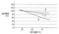
図11は、一般的なLEDの素子温度と赤色LED(R)、緑色LED(G)、青色LED(B)の各色の相対輝度との関係を表す特性図である。By the way, as a general LED characteristic, the luminous efficiency decreases as the temperature of the element increases.
FIG. 11 is a characteristic diagram showing the relationship between the element temperature of a general LED and the relative luminance of each color of the red LED (R), green LED (G), and blue LED (B).
図11においては素子温度が25℃の場合の輝度を100%とした場合の赤色R、緑色G、青色Bの各相対輝度を表している。図11に示すように赤色、緑色、青色の各色で輝度低下の割合が異なっており、特に赤色LEDの輝度低下は著しい。これらの輝度低下を補償するため、バックライト装置では各色の輝度検出が可能なカラーセンサで輝度を検出し、目標輝度になるようにフィードバック制御を行なうことが通常である。 FIG. 11 shows the relative luminance of red R, green G, and blue B when the luminance when the element temperature is 25 ° C. is 100%. As shown in FIG. 11, the ratio of luminance reduction is different for each of red, green, and blue, and the luminance reduction of the red LED is particularly remarkable. In order to compensate for such a decrease in luminance, the backlight device normally detects the luminance with a color sensor capable of detecting the luminance of each color, and performs feedback control so as to achieve the target luminance.
ここで、赤色LEDは輝度低下を起こすだけではなく、素子の温度が変化すると波長が変動する特性を示すことが知られている。 Here, it is known that the red LED not only causes a decrease in luminance, but also exhibits a characteristic that the wavelength varies as the temperature of the element changes.
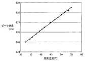
図12は、赤色LEDにおける周囲温度とピーク波長との関係の測定結果である。
図12を参照して、赤色LEDは素子の周囲温度が上昇すると、発光のピーク波長が長波長側にシフトすることがわかる。一方、図示はしないが青色、および緑色LEDのピーク波長は周囲温度が上昇しても、赤色LEDのように、顕著には変動はしない。つまり周囲の温度が上昇した場合、赤色LEDのみ波長が変動することとなり、温度上昇の前後でバックライトの色みが変化することになる。これは液晶用のバックライト装置としては好ましくない。FIG. 12 is a measurement result of the relationship between the ambient temperature and the peak wavelength in the red LED.
Referring to FIG. 12, it can be seen that when the ambient temperature of the red LED increases, the peak wavelength of light emission shifts to the long wavelength side. On the other hand, although not shown, the peak wavelengths of the blue and green LEDs do not change significantly as the red LEDs even when the ambient temperature rises. That is, when the ambient temperature rises, the wavelength of only the red LED changes, and the color of the backlight changes before and after the temperature rise. This is not preferable as a backlight device for liquid crystal.
特開2005−331644号公報(特許文献1)に記載されたバックライト装置においては、上記の温度上昇による色み変化の対策として、LED近傍の温度を検出する温度センサと、画面の色みおよび輝度を検出可能なカラーセンサを設け、上記温度センサによる検出温度によって上記カラーセンサを用いた各LEDの輝度制御の制御目標量を変化させている。
しかしながら、特開2005−331644号公報(特許文献1)に記載されたバックライト装置のように、LED近傍の温度を測定することで全体の制御量を調整する方式では、カラーセンサの他に温度センサを新たに設ける必要がありコストアップ要因となる。また、このバックライト装置ではLED近傍の温度を測定して制御量を変化させるとしている。このような構成では、測定した温度データとLEDの周囲温度との相関がとれていないと、正確な制御は行なえない。 However, as in the backlight device described in Japanese Patent Application Laid-Open No. 2005-331644 (Patent Document 1), in the method of adjusting the entire control amount by measuring the temperature in the vicinity of the LED, in addition to the color sensor, the temperature It is necessary to provide a new sensor, which increases the cost. In this backlight device, the control amount is changed by measuring the temperature in the vicinity of the LED. In such a configuration, accurate control cannot be performed unless the measured temperature data is correlated with the ambient temperature of the LED.
一方、小谷,「LEDバックライトがテレビの色を変える」,日経エレクトロニクス,日経BP社,2004年12月20日,第889号,p.57−62(非特許文献1)に示されるような、LEDを液晶パネルの直下に配置する直下型バックライト装置の場合、各LEDは液晶パネルの直下に広範囲に配置されるため、周囲の温度はそれぞれのLEDの配置されている場所によって大きく異なる。このため、測定した温度データと各LEDの周囲温度との相関を取ることは非常に困難である。 On the other hand, Otani, “LED backlights change the color of television”, Nikkei Electronics, Nikkei BP, December 20, 2004, No. 889, p. In the case of a direct type backlight device in which LEDs are arranged directly under a liquid crystal panel as shown in 57-62 (Non-Patent Document 1), each LED is arranged in a wide range directly under the liquid crystal panel, so that the ambient temperature Varies greatly depending on the location of each LED. For this reason, it is very difficult to correlate the measured temperature data with the ambient temperature of each LED.
これらの相関を取るためにLEDの個数と同等程度の温度センサを配置することも理論上考えられるが、非常にコストがかかり、かつ制御量が膨大となるので現実的ではない。 In order to obtain these correlations, it is theoretically possible to arrange a temperature sensor equivalent to the number of LEDs, but this is not practical because it is very costly and requires a large amount of control.
また、仮にLEDの個数と同等程度の温度センサを用意したとしても配置上の問題がある。すなわち、赤色、緑色、青色の各LEDは混色のために、それぞれ近接して配置する。このため温度センサを、これらのLEDに近接した位置に配置するのはスペース的に難しく、各LEDから、ある程度離れた位置に設けざるを得ない。結果として、測定した温度データはLED周囲温度と相関を取ることは困難となる。 Even if a temperature sensor equivalent to the number of LEDs is prepared, there is a problem in arrangement. That is, the red, green, and blue LEDs are arranged close to each other for color mixing. For this reason, it is difficult in terms of space to dispose the temperature sensor in a position close to these LEDs, and it is necessary to provide them at positions away from each LED to some extent. As a result, it is difficult to correlate the measured temperature data with the LED ambient temperature.
以上のように、温度センサにて検出される温度は、必ずしもLEDの周囲温度と相関が取れているとは限らない。このため、特許文献1記載のバックライト制御装置では、温度変化による色み、および輝度の変化を正確に補償できないという問題がある。 As described above, the temperature detected by the temperature sensor is not necessarily correlated with the ambient temperature of the LED. For this reason, the backlight control device described in
本発明の目的は、光源であるLEDの温度による輝度、色みの変化に対する補償を、簡易な構成で、かつ安定的に行なうことができるバックライト装置およびバックライト制御方法を提供することである。 An object of the present invention is to provide a backlight device and a backlight control method that can stably perform compensation for changes in luminance and color depending on the temperature of an LED, which is a light source, with a simple configuration. .
この発明は、要約すると、バックライト装置であって、発光輝度の調整が可能な複数種類の光源と、複数種類の光源における各種類の光源の発光輝度を検出するセンサ手段と、センサ手段の出力値を記憶するセンサ値メモリ手段と、センサ手段の出力基準値を予め記憶しているセンサ基準値メモリ手段と、センサ手段の出力とセンサ値メモリ手段の出力とセンサ基準値メモリ手段の出力とを受けて複数種類の光源の発光輝度をフィードバック制御する制御手段とを備える。制御手段は、センサ値メモリ手段とセンサ基準値メモリ手段との出力に応じて、各種類の光源の輝度目標値の演算を行なう補正値演算部と、補正値演算部にて演算された輝度目標値とセンサ手段にて検出された発光輝度とを比較して各種類の光源の発光輝度を制御するための制御量を演算する制御量演算部とを含む。 In summary, the present invention is a backlight device, which is a plurality of types of light sources capable of adjusting emission luminance, sensor means for detecting the emission luminance of each type of light source in the plurality of types of light sources, and output of the sensor means Sensor value memory means for storing the value, sensor reference value memory means for storing the output reference value of the sensor means in advance, output of the sensor means, output of the sensor value memory means, and output of the sensor reference value memory means And a control means for feedback-controlling the light emission luminance of the plurality of types of light sources. The control means includes a correction value calculation unit that calculates a luminance target value of each type of light source according to outputs from the sensor value memory means and the sensor reference value memory means, and a luminance target calculated by the correction value calculation unit. And a control amount calculation unit that calculates a control amount for controlling the light emission luminance of each type of light source by comparing the value and the light emission luminance detected by the sensor means.
好ましくは、制御手段は、補正値演算部において輝度目標値の演算を行なう場合、一旦、フィードバック制御を中断し、各種類の光源を予め設定している所定値で発光させる。センサ値メモリ手段は、センサ手段により検出された各種類の光源のうちの単一種類もしくは全てではない複数種類の光源の発光輝度を記憶する。補正値演算部は、センサ値メモリ手段の出力と、センサ基準値メモリ手段の出力とから、単一種類もしくは全てではない複数種類の光源の相対輝度を検出する。制御量演算部は、相対輝度に応じて全ての光源の輝度の制御目標値を演算し、その制御目標値を設定した後、制御手段のフィードバック制御を再開させる。 Preferably, when the correction value calculation unit calculates the luminance target value, the control unit temporarily interrupts the feedback control and causes each type of light source to emit light at a predetermined value set in advance. The sensor value memory means stores the light emission luminances of a single type or not all of the types of light sources detected by the sensor means. The correction value calculation unit detects the relative luminance of a single type or a plurality of types of light sources that are not all from the output of the sensor value memory unit and the output of the sensor reference value memory unit. The control amount calculation unit calculates the control target value of the luminance of all the light sources according to the relative luminance, sets the control target value, and then restarts the feedback control of the control means.
好ましくは、複数種類の光源は、赤、緑、青の3原色をそれぞれ発光波長とする発光ダイオードを含む。 Preferably, the plurality of types of light sources include light emitting diodes each having three primary colors of red, green, and blue as emission wavelengths.
好ましくは、制御手段は、複数種類の光源のうちの赤色以外の種類の光源に対応するセンサ手段の出力と赤色以外の種類の光源に対応するセンサ基準値メモリ手段の出力とを比較して、少なくとも赤色の光源の輝度目標値を設定する。 Preferably, the control means compares the output of the sensor means corresponding to the light source other than red among the plurality of types of light sources and the output of the sensor reference value memory means corresponding to the light source other than red, A luminance target value of at least a red light source is set.
この発明の他の局面に従うと、バックライト装置であって、発光輝度の調整が可能な複数種類の光源と、複数種類の光源の積算発光時間を計測する積算時間計測手段と、複数種類の光源における各種類の光源の発光輝度を検出するセンサ手段と、センサ手段の出力値を記憶するセンサ値メモリ手段と、積算時間計測手段の計測値に対応したセンサ手段の出力基準値を予め記憶しているセンサ基準値メモリ手段と、センサ手段の出力とセンサ値メモリ手段の出力とセンサ基準値メモリ手段の出力とを受けて複数種類の光源の発光輝度をフィードバック制御する制御手段とを備える。制御手段は、センサ値メモリ手段とセンサ基準値メモリ手段との出力に応じて、各種類の光源の輝度目標値の演算を行なう補正値演算部と、補正値演算部にて演算された輝度目標値とセンサ手段にて検出された発光輝度とを比較して各種類の光源の発光輝度を制御するための制御量を演算する制御量演算部とを含む。 According to another aspect of the present invention, the backlight device includes a plurality of types of light sources capable of adjusting the light emission luminance, an integrated time measuring unit that measures an integrated light emission time of the plurality of types of light sources, and a plurality of types of light sources. Sensor means for detecting the emission luminance of each type of light source, sensor value memory means for storing the output value of the sensor means, and output reference values of the sensor means corresponding to the measurement values of the integrated time measuring means are stored in advance. Sensor reference value memory means, and control means for feedback-controlling the light emission luminance of a plurality of types of light sources in response to the output of the sensor means, the output of the sensor value memory means, and the output of the sensor reference value memory means. The control means includes a correction value calculation unit that calculates a luminance target value of each type of light source according to outputs from the sensor value memory means and the sensor reference value memory means, and a luminance target calculated by the correction value calculation unit. And a control amount calculation unit that calculates a control amount for controlling the light emission luminance of each type of light source by comparing the value and the light emission luminance detected by the sensor means.
好ましくは、制御手段は、補正値演算部において輝度目標値の演算を行なう場合、一旦、フィードバック制御を中断し、各種類の光源を予め設定している所定値で発光させる。センサ値メモリ手段は、センサ手段により検出された各種類の光源のうちの単一種類もしくは全てではない複数種類の光源の発光輝度を記憶する。補正値演算部は、センサ値メモリ手段の出力と、センサ基準値メモリ手段の出力とから、単一種類もしくは全てではない複数種類の光源の相対輝度を検出する。制御量演算部は、相対輝度に応じて全ての光源の輝度の制御目標値を演算し、その制御目標値を設定した後、制御手段のフィードバック制御を再開させる。 Preferably, when the correction value calculation unit calculates the luminance target value, the control unit temporarily interrupts the feedback control and causes each type of light source to emit light at a predetermined value set in advance. The sensor value memory means stores the light emission luminances of a single type or not all of the types of light sources detected by the sensor means. The correction value calculation unit detects the relative luminance of a single type or a plurality of types of light sources that are not all from the output of the sensor value memory unit and the output of the sensor reference value memory unit. The control amount calculation unit calculates the control target value of the luminance of all the light sources according to the relative luminance, sets the control target value, and then restarts the feedback control of the control means.
好ましくは、複数種類の光源は、赤、緑、青の3原色をそれぞれ発光波長とする発光ダイオードを含む。 Preferably, the plurality of types of light sources include light emitting diodes each having three primary colors of red, green, and blue as emission wavelengths.
好ましくは、制御手段は、複数種類の光源のうちの赤色以外の種類の光源に対応するセンサ手段の出力と赤色以外の種類の光源に対応するセンサ基準値メモリ手段の出力とを比較して、少なくとも赤色の光源の輝度目標値を設定する。 Preferably, the control means compares the output of the sensor means corresponding to the light source other than red among the plurality of types of light sources and the output of the sensor reference value memory means corresponding to the light source other than red, A luminance target value of at least a red light source is set.
好ましくは、センサ基準値は、積算時間計測手段の計測結果が大きくなるにつれて小さくなるように設定されている。 Preferably, the sensor reference value is set so as to decrease as the measurement result of the integrated time measuring means increases.
この発明のさらに他の局面に従うと、バックライト装置であって、発光輝度の調整が可能な複数種類の光源と、複数種類の光源における各種類の光源の発光輝度を検出するセンサ手段と、センサ手段の出力基準値を予め記憶しているセンサ基準値メモリ手段と、センサ手段の出力とセンサ基準値メモリ手段の出力とに応じて複数種類の光源の発光輝度をフィードバック制御する制御手段とを備える。制御手段は、一旦、フィードバック制御を中断し、各種類の光源を予め設定している電流値で発光させて、センサ手段により検出された各種類の光源のうちの少なくとも一種類の光源の発光輝度に基づいて他の種類の光源の輝度の制御目標値を設定した後、フィードバック制御を再開させる。 According to still another aspect of the present invention, the backlight device is a plurality of types of light sources capable of adjusting the emission luminance, sensor means for detecting the emission luminance of each type of light source in the plurality of types of light sources, and a sensor. Sensor reference value memory means for storing the output reference value of the means in advance, and control means for performing feedback control of the light emission luminance of the plurality of types of light sources according to the output of the sensor means and the output of the sensor reference value memory means. . The control means temporarily interrupts the feedback control, causes each type of light source to emit light at a preset current value, and emits light of at least one type of light source detected by the sensor means. After setting the control target value of the brightness of another type of light source based on the above, the feedback control is resumed.
好ましくは、バックライト装置は、複数種類の光源の積算発光時間を計測する積算時間計測手段をさらに備える。センサ基準値メモリ手段は、積算時間計測手段の計測値に対応したセンサ手段の出力基準値を予め記憶する。 Preferably, the backlight device further includes an accumulated time measuring unit that measures accumulated light emission times of a plurality of types of light sources. The sensor reference value memory means stores in advance an output reference value of the sensor means corresponding to the measured value of the accumulated time measuring means.
好ましくは、出力基準値は、各種類の光源の積算発光時間が大きくなるにつれて、小さくなるように設定される。 Preferably, the output reference value is set so as to decrease as the accumulated light emission time of each type of light source increases.
この発明のさらに他の局面に従うと、発光輝度の調整が可能な複数種類の光源と、各種類の光源の発光輝度を検出するセンサ手段とを用いて各種類の光源の発光輝度をフィードバック制御するバックライト制御方法であって、各種類の光源の発光輝度の制御目標値設定のため、一旦、フィードバック制御を中断するステップと、各種類の光源を予め設定している所定値で発光させ、各種類の光源のうちの単一種類、もしくは全種類ではない複数種類の光源の発光状態をセンサ手段により検出するステップと、センサ手段によって検出した検出値と、予め記憶しているセンサ手段の出力基準値とを比較して、各種類の光源のうちの単一種類、もしくは全種類ではない複数種類の光源の出力基準値に対する相対輝度を検出し、相対輝度に応じて全種類の光源の発光輝度の制御目標値を演算するステップと、制御目標値を設定した後、フィードバック制御を再開するステップとを備える。 According to yet another aspect of the present invention, the emission luminance of each type of light source is feedback controlled using a plurality of types of light sources capable of adjusting the emission luminance and sensor means for detecting the emission luminance of each type of light source. In the backlight control method, in order to set the control target value of the emission luminance of each type of light source, the step of temporarily interrupting the feedback control, and each type of light source is made to emit light at a predetermined value, A step of detecting the light emission states of a single type of light sources among a plurality of types of light sources, or a detection value detected by the sensor means, and an output reference of the sensor means stored in advance The relative brightness of each type of light source with respect to the output reference value of a single type or multiple types of light sources is detected. Comprising a step of computing the control target value of the emission luminance of the kind of light source, after setting the control target value, and resuming feedback control.
好ましくは、複数種類の光源は赤、緑、青の3原色をそれぞれ発光波長とする発光ダイオードを含む。 Preferably, the plurality of types of light sources include light emitting diodes each having three primary colors of red, green, and blue as emission wavelengths.
好ましくは、制御目標値を演算するステップは、複数種類の光源のうちの赤色以外の種類の光源に対応するセンサ手段の出力と、赤色以外の種類の光源に対応する出力基準値とを比較して全光源の輝度の制御目標値を設定する。 Preferably, the step of calculating the control target value compares the output of the sensor means corresponding to a light source of a type other than red among the plurality of types of light sources and an output reference value corresponding to a light source of a type other than red. Set the control target value for the brightness of all light sources.
好ましくは、バックライト制御方法は、各種類の光源の積算発光時間を計測するステップをさらに備える。予め記憶しているセンサ手段の出力基準値は、各種類の光源の積算発光時間が大きくなるにつれて、小さくなるように設定される。 Preferably, the backlight control method further includes a step of measuring an accumulated light emission time of each type of light source. The output reference value of the sensor means stored in advance is set so as to decrease as the accumulated light emission time of each type of light source increases.
本願のバックライト制御装置によれば、温度センサ等を用いることなく周囲温度と相関のある赤色以外のLEDの相対輝度をカラーセンサで検出することで赤色LEDの波長変動の様子を推測するため、適切な輝度目標値を設定することができる。このため、温度変化に起因する赤色LEDの波長変動に対しても、何ら影響を受けないバックライト装置を、温度センサを新たに設けることなく実現することができる。さらに、青色、および緑色LEDは、赤色LEDの近傍に配置することが通常であるため、これらの周囲の温度が赤色LEDとほぼ同一である。その青色、および緑色LEDの相対輝度から赤色LEDの波長変動を推測し輝度目標値を変更する構成のため、非常に精度よくかつ安定にバックライト装置の色みを制御することが可能である。 According to the backlight control device of the present application, in order to infer the state of wavelength variation of the red LED by detecting the relative luminance of the LED other than the red color correlated with the ambient temperature without using a temperature sensor or the like, An appropriate luminance target value can be set. For this reason, it is possible to realize a backlight device that is not affected at all by the wavelength variation of the red LED caused by the temperature change without newly providing a temperature sensor. Further, since the blue and green LEDs are usually arranged in the vicinity of the red LED, the ambient temperature thereof is almost the same as that of the red LED. The configuration of estimating the wavelength variation of the red LED from the relative luminance of the blue and green LEDs and changing the luminance target value makes it possible to control the color of the backlight device very accurately and stably.
また本願の他のバックライト制御装置によれば、バックライト装置の積算点灯時間を計測して、その計測時間に応じて赤色LED以外のLEDの相対輝度を検出する基準値を変化させるため、LEDの経時変化による輝度低下が起こっても、相対輝度の検出には影響を及ぼさない。このため、常に、赤色LEDの波長の変動を検知することが可能であるので、LEDの経時変化が生じても安定して各LEDの制御目標値を設定でき、色みの変動がない安定したバックライト制御装置を得ることが可能である。 In addition, according to another backlight control device of the present application, the LED is used to measure the integrated lighting time of the backlight device and change the reference value for detecting the relative luminance of the LEDs other than the red LED according to the measurement time. Even if the luminance decreases due to the change with time, the detection of the relative luminance is not affected. Because of this, it is always possible to detect changes in the wavelength of the red LED, so even if the LED changes over time, the control target value for each LED can be set stably, and there is no change in color. It is possible to obtain a backlight control device.
さらに本願のバックライト制御方法によれば、温度センサ等を用いることなく、周囲温度と相関のある赤色以外のLEDの相対輝度をカラーセンサで検出することで、赤色LEDの波長変動の様子を推測するため、適切な輝度目標値を設定することができる。このため、温度変化に起因する赤色LEDの波長変動に対しても、何ら影響を受けないバックライト装置を、温度センサを新たに設けることなく実現することができる。さらに、赤色LEDの近傍に配置することが通常であるため、周囲の温度が赤色LEDとほぼ同一の青色、緑色のLEDの相対輝度から赤色LEDの波長変動を推測し輝度目標値を変更する構成のため、非常に精度よくかつ安定にバックライトの色みを制御することが可能である。 Furthermore, according to the backlight control method of the present application, the state of the wavelength variation of the red LED is estimated by detecting the relative luminance of the non-red LED correlated with the ambient temperature with the color sensor without using a temperature sensor or the like. Therefore, an appropriate luminance target value can be set. For this reason, it is possible to realize a backlight device that is not affected at all by the wavelength variation of the red LED caused by the temperature change without newly providing a temperature sensor. In addition, since it is usually placed near the red LED, the target temperature is changed by estimating the wavelength fluctuation of the red LED from the relative luminance of the blue and green LEDs whose ambient temperature is almost the same as the red LED. Therefore, it is possible to control the color of the backlight very accurately and stably.
さらに、本願の他のバックライト制御方法によれば、各光源の積算点灯時間を計測して、その計測時間に応じて、赤色LED以外のLEDの相対輝度を検出する基準値を変化させる。このため、LEDの経時変化による輝度低下が起こっても、相対輝度の検出には影響を及ぼさない。この結果、常に、赤色LEDの波長の変動を検知することが可能であるので、LEDの経時変化が生じても安定して各LEDの制御目標値を設定でき、非常に安定してバックライトの色みの変動を制御することが可能となる。 Furthermore, according to another backlight control method of the present application, the integrated lighting time of each light source is measured, and the reference value for detecting the relative luminance of the LEDs other than the red LED is changed according to the measurement time. For this reason, even if the luminance decreases due to the change of the LED over time, the detection of the relative luminance is not affected. As a result, it is always possible to detect changes in the wavelength of the red LED, so that even if the LED changes over time, the control target value of each LED can be set stably, and the backlight can be controlled very stably. It becomes possible to control variation in color.
以下、本発明の実施の形態について図面を参照しながら詳細に説明する。なお、図中同一または相当部分には同一符号を付してその説明は繰返さない。 Hereinafter, embodiments of the present invention will be described in detail with reference to the drawings. In the drawings, the same or corresponding parts are denoted by the same reference numerals and description thereof will not be repeated.
〔実施の形態1〕
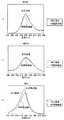
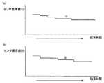
図1は、赤色、緑色、青色のLEDを長時間点灯させて、LEDの周囲温度が点灯直後に比較して約30℃上昇した場合の、LEDの輝度および波長を、分光放射輝度計にて測定したデータの一例である。図1(a)は青色LEDの点灯直後と温度上昇後、図1(b)は緑色LEDの点灯直後と温度上昇後、図1(c)は赤色LEDの点灯直後と温度上昇後の分光データをそれぞれ示している。[Embodiment 1]
Figure 1 shows the brightness and wavelength of a LED when the red, green, and blue LEDs are lit for a long time, and the ambient temperature of the LEDs has increased by about 30 ° C compared to immediately after lighting. It is an example of the measured data. Fig. 1 (a) shows the spectral data immediately after the blue LED lights up and after the temperature rises, Fig. 1 (b) shows the spectral data immediately after the green LED lights up and after the temperature rises, and Fig. 1 (c) shows the spectral data immediately after the red LED lights up and after the temperature rises. Respectively.
図1(a)、(b)より青色および緑色LEDは、温度上昇による効率の低下に起因する輝度低下が生じているが、ピーク波長は温度上昇の前後でほとんど変化していない。一方、図1(c)に示される赤色LEDは、輝度低下と同時にピーク波長が長波長側(635nm→639nm)に変動している。 From FIGS. 1 (a) and 1 (b), the blue and green LEDs have a decrease in luminance due to a decrease in efficiency due to a temperature increase, but the peak wavelength hardly changes before and after the temperature increase. On the other hand, in the red LED shown in FIG. 1 (c), the peak wavelength fluctuates to the long wavelength side (635 nm → 639 nm) simultaneously with the decrease in luminance.
上記のような特性を有するLEDを用いて、液晶用のバックライトを構成した場合、周囲温度の上昇に起因する輝度の低下を補償するため、各色の輝度検出が可能なカラーセンサで輝度を検出し、目標の輝度になるようにフィードバック制御を行なう。 When a liquid crystal backlight is configured using LEDs with the above characteristics, the brightness is detected by a color sensor that can detect the brightness of each color to compensate for the decrease in brightness caused by an increase in ambient temperature. Then, feedback control is performed to achieve the target luminance.
しかしながら、図1(c)に示すように、赤色LEDの波長は長波長側に変動するため、上記のようなフィードバック制御を施しても、赤色、緑色、青色を混色して実現した色みは一定にはならない。色みの変動を補償するには赤色LEDの波長変動を検出して、各色の輝度目標値を変動前の目標値と変更する必要がある。 However, as shown in FIG. 1 (c), since the wavelength of the red LED fluctuates to the long wavelength side, even if the feedback control as described above is performed, the color realized by mixing red, green, and blue is as follows. It will not be constant. To compensate for the color variation, it is necessary to detect the wavelength variation of the red LED and change the luminance target value of each color to the target value before the variation.
ここで、図11に示すように緑色、青色LEDの相対輝度と各LEDの周囲温度との間には相関がある。また、図12に示すようにLEDの周囲温度と赤色LEDの波長変動量にも相関がある。つまり、青色LEDおよび緑色LEDの相対輝度の変動量と赤色LEDの波長変動量には相関がある。以上より、青色および緑色LEDの相対輝度の変動量を検出することで、赤色LEDの波長変動量は推測できる。 Here, as shown in FIG. 11, there is a correlation between the relative luminance of the green and blue LEDs and the ambient temperature of each LED. Also, as shown in FIG. 12, there is a correlation between the ambient temperature of the LED and the wavelength variation of the red LED. That is, there is a correlation between the fluctuation amount of the relative luminance of the blue LED and the green LED and the fluctuation amount of the wavelength of the red LED. From the above, the wavelength fluctuation amount of the red LED can be estimated by detecting the fluctuation amount of the relative luminance of the blue and green LEDs.
このため、本実施の形態のバックライト装置およびその制御方法では、青色および緑色LEDの相対輝度から、各LEDの輝度目標値を変更することで、赤色LEDの波長変動による色みの変化を補償しようとするものである。 For this reason, the backlight device and its control method of the present embodiment compensate for changes in color due to wavelength fluctuations of the red LED by changing the target luminance value of each LED from the relative luminance of the blue and green LEDs. It is something to try.
続いて、図2、3、4、5を用いて本発明の実施の形態1におけるバックライト制御装置の具体的な構成を説明する。 Next, a specific configuration of the backlight control apparatus according to
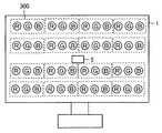
図2は、本発明の実施の形態1におけるバックライト制御装置で用いられる、LEDバックライト部分を示す概略模式図である。図2には液晶パネルと光学シート類を外した状態の液晶表示装置を前面から見た模式図が示されている。 FIG. 2 is a schematic diagram showing an LED backlight portion used in the backlight control apparatus according to
LEDバックライト部1は、LEDを液晶パネルの直下に配置して液晶パネルを照らす、いわゆる直下型のバックライトである。LED群300は、赤色(R)、緑色(G)、青色(B)の各LEDから構成される。このLED群は液晶パネルの直下に複数個、均等に配置され液晶パネルを照らしている。カラーセンサ5は、液晶パネルからの反射光を受光することで赤、緑、青の各LEDの発光輝度を検出するものである。 The
図2に示すように赤、緑、青の各色のLEDは混色が必要なため、各色は互いに近接して配置される。このため、各色LEDの周囲の温度は、ほぼ同一と見なしてよい。図2に示されるように、LEDバックライト部1は、LED群300とカラーセンサ5および後述するドライバ9を含むが、温度センサは設けられていない。 As shown in FIG. 2, the red, green, and blue LEDs need to be mixed, so that the colors are arranged close to each other. For this reason, the ambient temperature of each color LED may be regarded as substantially the same. As shown in FIG. 2, the
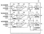
図3は、実施の形態1におけるバックライト制御装置の具体的な構成を示した構成図である。図2でその概略的な構成を示したLEDバックライト部1は、発光輝度の調整が可能な赤色LED部2、緑色LED部3、青色LED部4と、各LEDの発光輝度を検出するカラーセンサ5と、カラーセンサ5の出力基準値を予め記憶しているセンサ基準値メモリ15と、カラーセンサ5の出力とセンサ基準値メモリ15の出力とに応じてLEDの発光輝度をフィードバック制御する制御装置17と、ドライバ9とを備える。制御装置17は、一旦、フィードバック制御を中断し、各種類の光源を予め設定している電流値で発光させて、カラーセンサ5により検出された各LEDのうちの少なくとも一種類のLEDの発光輝度に基づいて他の種類のLEDの輝度の制御目標値を設定した後、フィードバック制御を再開させる。 FIG. 3 is a configuration diagram showing a specific configuration of the backlight control apparatus according to the first embodiment. The
カラーセンサ5は、赤色用センサ部6、緑色センサ部7、青色用センサ部8を含む。赤色用センサ部6は、赤色の波長領域のみを透過するフィルタと、受光部、および受光部からの電流出力を電圧変換するI/V変換部とを含む。緑色センサ部7は、緑色の波長領域のみを透過するフィルタと、受光部および受光部からの電流出力を電圧変換するI/V変換部とを含む。青色用センサ部8は、青色の波長領域のみを透過するフィルタと、受光部、および受光部からの電流出力を電圧変換するI/V変換部とを含む。 The
ドライバ9は、赤色LEDを駆動する赤色用ドライバ部10、緑色LEDを駆動する緑色用ドライバ部11、青色LEDを駆動する青色用ドライバ部12を含む。これらの各ドライバ部10、11、および12は後述する制御装置17から演算、送信されるPWMデータに応じて、赤色、緑色、青色の各LEDをそれぞれPWM駆動するものである。 The driver 9 includes a
A/D変換部13は、カラーセンサ5にて検出される各LEDのセンサ出力(輝度情報)をデジタルデータに変換する。センサ値メモリ14は、A/D変換部13にてデジタルデータに変換されたセンサ出力(輝度情報)を記憶するものである。センサ基準値メモリ15は、各色のカラーセンサの出力基準値を格納するものである。 The A /
各色のカラーセンサの出力基準値とは、出荷時等の初期状態において、予め設定している電流値(PWM値)を各LEDに印加した場合のカラーセンサの出力のことである。このセンサ基準値メモリ15に記憶されているデータは更新されるものではない。初期値メモリ16は、電源投入時や、相対輝度の検出時に各LEDを駆動する電流値(PWM値)を記憶しておくものである。なお、この初期値メモリ16の記憶内容も出荷時等の初期状態に設定されるものであり、更新されるものではない。 The output reference value of the color sensor for each color is the output of the color sensor when a preset current value (PWM value) is applied to each LED in an initial state such as at the time of shipment. The data stored in the sensor
制御装置17は、通常CPU等のプロセッサにより構成される。この制御装置17は全体制御部18、補正値演算部19、制御量演算部20を含む。全体制御部18はバックライトの点灯、消灯、カラーセンサ5の出力に基づいた輝度制御のON、OFF等、バックライト装置の全体動作を制御するものである。補正値演算部19は、各LEDの温度上昇に応じて制御目標値を変更して制御量演算部20に出力するものである。制御量演算部20は、補正値演算部19にて演算された各LEDの輝度目標値と、A/D変換部13からの入力である各LEDの輝度検出結果との誤差を算出し、その誤差がなくなるように各色のLEDのPWM値を変更する、いわゆる輝度フィードバックを行なうものである。 The
図4は、制御装置17における補正値演算部19の具体的な構成を示す構成図である。 図4を参照して、補正値演算部19は、規格化処理部191,192と、目標値テーブル193とを含む。規格化処理部191、192は、センサ値メモリより読み出した緑色および青色用センサ部の出力を、センサ基準値メモリ15の基準出力値で規格化するものであり、緑色、および青色LEDの相対輝度を演算する。 FIG. 4 is a configuration diagram illustrating a specific configuration of the correction
目標値テーブル193は、相対輝度に応じて赤色、緑色、青色の各LEDの輝度制御目標値を制御量演算部20に出力するものである。この目標値テーブル193に格納されているデータは、出荷時等の初期状態において予め格納されているものである。 The target value table 193 outputs the luminance control target values of the red, green, and blue LEDs to the control
目標値の設定方法としては、基準状態と比較した青色LED、緑色LEDの相対輝度と赤色LEDの波長変動量との関係を外部の測定器を用いて測定しておき、さらに赤色LEDの波長が変動した場合でも、所望の白色が得られるような各色の輝度を算出しておく。そして、この算出した目標値と相対輝度との関係をテーブル化して、目標値テーブル193に格納しておく。 The target value can be set by measuring the relationship between the relative luminance of the blue and green LEDs compared to the reference state and the amount of wavelength fluctuation of the red LED using an external measuring instrument. The luminance of each color is calculated so that a desired white color can be obtained even if it fluctuates. Then, the relationship between the calculated target value and relative luminance is tabulated and stored in the target value table 193.
図5は、図3における制御量演算部20の具体的な構成を示す構成図である。
図5を参照して、制御量演算部20は、差動増幅器201〜203と、ゲイン付加部204〜206と、積分器207〜209と、切替スイッチ210〜212と、PMW変換部213〜215とを含む。FIG. 5 is a configuration diagram illustrating a specific configuration of the control
Referring to FIG. 5, control
差動増幅器201、202、203は、赤色、緑色、青色の各センサ出力(デジタルデータ)と補正値演算部19にて演算された赤色、緑色、青色の各LEDの輝度目標値との誤差を演算するものである。 The
ゲイン付加部204、205、206は、差動増幅器の出力である各色の輝度目標値と、センサにより検出した現在輝度との誤差を所定ゲイン倍するものである。このゲイン付加部204、205、206によって、輝度を制御するフィードバック制御系の制御帯域を設定することができる。 The
積分器207、208、209は、ゲイン付加部204、205、206にてゲイン倍された各色の輝度誤差を積分することで、これらの誤差がなくなるように制御する。積分器207は赤色用、積分器208は緑色用、積分器209は青色用の誤差を、それぞれ積分する積分器である。 The
切替スイッチ210、211、212は、全体制御部18からの指示に応じて、それぞれ上記の積分器207、208、209の出力と初期値メモリ16の出力とを切り替えるものである。 The change-over
PWM変換部213、214、215は、切替スイッチ210、211、212の出力である制御量を、PWM値に変換するものであり、切替スイッチ210、211、212の出力に応じてドライバ9に出力するPWMのパルス幅を決定するものである。各色のLEDは、このPWM変換部213、214、215の各出力のPWM値に応じて駆動される。 The
上記のようにして、バックライト制御装置は構成される。続いて本発明のバックライト制御方法および装置の具体的な動作を、図6および図7を用いて詳細に説明する。 The backlight control device is configured as described above. Next, specific operations of the backlight control method and apparatus of the present invention will be described in detail with reference to FIGS.
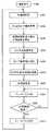
図6は、本発明の実施の形態1におけるバックライト装置およびその制御方法の具体的な動作を説明するフローチャートである。 FIG. 6 is a flowchart for explaining specific operations of the backlight device and the control method thereof according to
図6、図7を参照して、まず電源が投入される(ステップS100)と、制御装置17は切替スイッチ210、211、212が初期値メモリ16からの入力を選択するように設定する。つまり、初期値メモリ16に記憶されている所定のPWM値で各色のLEDは駆動される(ステップS101)。 Referring to FIGS. 6 and 7, when power is first turned on (step S <b> 100),
そして、予め設定されている所定のPWM値で各色のLEDを駆動している場合のカラーセンサ5の各色のセンサ出力(デジタルデータ)を、センサ値メモリ14に記憶し(ステップS102)、センサ基準値メモリ15の出力と比較して相対輝度を検出する(ステップS103)。検出した相対輝度にしたがって目標値テーブル193から目標値を出力し(ステップS104)、制御目標値として設定する(ステップS105)。 Then, the sensor output (digital data) of each color of the
制御目標値が設定された時点で制御装置17は切替スイッチ210、211、212がA/D変換部13からの入力を選択するように設定する。このことで、カラーセンサ5にて検出される各色の輝度が、制御目標値に一致するようにフィードバック制御が開始される(ステップS106)。 When the control target value is set, the
所定時間が経過するまでフィードバック制御をONの状態のまま、つまり目標値は一定のままで駆動が行われる(ステップS107)。ここでいう所定時間は、赤色LEDの波長が変動する時間を予め測定しておいた上で、その波長が変動することにより全体の色みが変わる時間よりも十分に短い間隔に設定しておく必要がある。 The drive is performed with the feedback control kept ON until the predetermined time has elapsed, that is, the target value remains constant (step S107). The predetermined time here is set to an interval sufficiently shorter than the time when the whole color changes due to the change of the wavelength after measuring the time when the wavelength of the red LED changes in advance. There is a need.
この所定時間が経過した場合、フィードバック制御をOFFするために、切替スイッチ210、211、212が初期値メモリ16からの入力を選択するように設定する(ステップS108)。そして、再び各色のLEDの相対輝度を検出し、目標値を演算、設定し、フィードバック制御をON(ステップS101〜S107)する。本発明におけるバックライト制御装置は、装置に電源が投入されている間、継続して本ステップに則って制御を行なう。 When the predetermined time has elapsed, in order to turn off the feedback control, the change-over
図7は、図6のステップS105において設定される赤色のLEDの輝度目標値の設定例を示した図である。 FIG. 7 is a diagram showing a setting example of the luminance target value of the red LED set in step S105 of FIG.
図7において、時刻t0に電源が投入されたとする。電源投入直後からLEDの周囲温度は上昇するため、赤色LEDの波長は、長波長側に変動する。赤色LEDの波長は通常635nm近辺であるため、この波長が長波長側に変動すると等色関数/x(λ) (エックス・バー・ラムダ)の感度が、元の波長に比較して小さくなる。(なお、ここでは「/]はxに付される上付きラインの代わりに用いるものとする。)このため、等色関数と輝度との乗算結果である刺激値xの値は小さくなる。つまり、波長変動の影響で全体の色みが変化する(x値が低下する)。 In FIG. 7, it is assumed that power is turned on at time t0. Since the ambient temperature of the LED rises immediately after the power is turned on, the wavelength of the red LED changes to the longer wavelength side. Since the wavelength of the red LED is usually around 635 nm, the sensitivity of the color matching function / x (λ) (X bar lambda) becomes smaller than the original wavelength when the wavelength fluctuates to the longer wavelength side. (Here, “/” is used in place of the superscript line attached to x.) For this reason, the value of the stimulus value x, which is the result of multiplication of the color matching function and the luminance, becomes small. The overall color changes due to the influence of wavelength fluctuation (x value decreases).
この状態において、赤色LEDの輝度が高くなるように設定すると、刺激値xの値を大きくすることができる。結果として、赤色LEDの波長変動に起因する色みの変化を補償することができる。図7では、時刻t1、t2、t3、t4の各時刻にて、赤色LEDの目標輝度を少しずつ高くすることで、赤色LEDの波長変動による色みの変化の補償を行っている。 In this state, if the brightness of the red LED is set to be high, the value of the stimulus value x can be increased. As a result, it is possible to compensate for the change in color caused by the wavelength variation of the red LED. In FIG. 7, at each of the times t1, t2, t3, and t4, the target luminance of the red LED is gradually increased to compensate for the change in color due to the wavelength variation of the red LED.
上記のような手順で、各色のLEDの輝度制御目標値を設定することにより、赤色LEDの波長が変動しても、各色のLEDを混色して実現する白色にはなんら影響を及ぼさないバックライト制御装置を実現することができる。 By setting the brightness control target value of each color LED in the above procedure, the backlight that does not affect the white color that is realized by mixing the LEDs of each color even if the wavelength of the red LED fluctuates A control device can be realized.
上記のようにして本発明のバックライト制御方法および装置は、各色のLEDの輝度を制御する。本発明の実施の形態1におけるバックライト装置によれば、赤色LEDの周囲温度と相関のある、赤色以外のLEDの相対輝度をカラーセンサで検出する。そして、この相対輝度から、赤色LEDの波長変動の様子を推測し、輝度目標値を設定する。 As described above, the backlight control method and apparatus of the present invention controls the luminance of each color LED. According to the backlight device in the first embodiment of the present invention, the color sensor detects the relative luminance of the LEDs other than red, which has a correlation with the ambient temperature of the red LED. Then, from this relative luminance, the state of wavelength variation of the red LED is estimated, and a luminance target value is set.
このため、温度センサ等の外部センサを新たに設けることなく、赤色LEDの波長が変動しても何ら影響を受けないバックライト制御装置を実現することができる。さらに、赤、緑、青の各色LEDはそれぞれ近傍に配置されるため、各LEDの周囲の温度は同一であると考えることができる。このため、温度センサで温度を検出する場合とは異なり、非常に精度よくかつ安定にバックライト装置の色みを制御することができる。 For this reason, it is possible to realize a backlight control device that is not affected even if the wavelength of the red LED fluctuates without newly providing an external sensor such as a temperature sensor. Furthermore, since the red, green, and blue color LEDs are arranged in the vicinity, it can be considered that the temperature around each LED is the same. Therefore, unlike the case where the temperature is detected by the temperature sensor, the color of the backlight device can be controlled with high accuracy and stability.
なお、本実施の形態1においては赤色以外の緑色、青色の両方の相対輝度検出結果から制御目標値を算出する構成としているが、青色のみ、あるいは緑色のみの相対輝度にて制御目標値を算出する構成としても、同様の効果が得られる。 In the first embodiment, the control target value is calculated from the relative luminance detection results of both green and blue other than red. However, the control target value is calculated using only blue or only green relative luminance. The same effect can be obtained with this configuration.
また、同様に本実施の形態1におけるバックライト装置では、説明の便宜上、赤色LEDの輝度目標値のみを変更する構成としているが、各色全てのLEDの輝度目標値を適切に変更する構成としてもよい。さらに本実施の形態1において、バックライトの光源としては赤色、緑色、青色の3種類のLEDの場合について説明を行ったが、上記の3種類だけではなく、他の色のLEDを追加して構成しても同様の効果が得られる。 Similarly, in the backlight device according to the first embodiment, only the luminance target value of the red LED is changed for convenience of explanation, but the luminance target value of the LEDs of all the colors may be appropriately changed. Good. Furthermore, in the first embodiment, the case of three types of LEDs of red, green, and blue has been described as the light source of the backlight. However, not only the above three types but also LEDs of other colors are added. Even if configured, the same effect can be obtained.
また、図1(b)に示す緑色の相対輝度の低下の度合いは、図1(a)に示す青色の相対輝度の低下の度合いに比較して小さくなっている。これは用いるLEDチップ固有のものである。本実施の形態1におけるバックライト制御方法および装置においては、出荷時等の初期状態で、各色のLEDの特性を測定、記憶するため、各色のLEDの温度特性がいかなる特性を取るものであっても、動作への影響はない。 In addition, the degree of decrease in green relative luminance shown in FIG. 1B is smaller than the degree of decrease in blue relative luminance shown in FIG. This is unique to the LED chip used. In the backlight control method and apparatus according to the first embodiment, the characteristics of the LED of each color are measured and stored in the initial state at the time of shipment or the like. However, there is no effect on the operation.
さらに、本実施の形態1においては、各色のLEDの発光輝度検出のために、カラーセンサを用いる構成としているが、カラーセンサ以外のセンサを用いても良い。例えば、カラーフィルタを持たない、受光素子のみからなるセンサを用いても発光輝度の検出は可能である。 Furthermore, in the first embodiment, a color sensor is used to detect the light emission luminance of each color LED, but a sensor other than the color sensor may be used. For example, it is possible to detect the light emission luminance even if a sensor having only a light receiving element without a color filter is used.
このようなセンサを用いる場合、赤、緑、青の各LEDの点灯タイミングをそれぞれ異ならせて、各LEDのうちの一色のみが点灯しているタイミングを設ける。そして、そのタイミングで各LEDの輝度を検出することで、カラーフィルタを用いた場合と同様の効果を得ることができる。 When such a sensor is used, the lighting timing of each of the red, green, and blue LEDs is made different so that only one color of each LED is lit. Then, by detecting the luminance of each LED at that timing, the same effect as when a color filter is used can be obtained.
〔実施の形態2〕
本発明のさらに別の実施形態について、図面に基づいて説明すれば以下の通りである。なお、説明の便宜上、実施の形態1で用いたものと同じ機能を有する部材には同じ符号を付して説明は繰返さない。[Embodiment 2]
Still another embodiment of the present invention will be described below with reference to the drawings. For convenience of explanation, members having the same functions as those used in
図8は、本発明における実施の形態2による、バックライト制御装置の具体的な構成を示した構成図である。 FIG. 8 is a configuration diagram showing a specific configuration of the backlight control apparatus according to the second embodiment of the present invention.
図8においてセンサ基準値メモリ15Aは、実施の形態1におけるセンサ基準値メモリ15と同等の目的をなすものであり、緑色および青色LEDの相対輝度を検出する際の基準となる輝度を予め記憶しているものである。積算時間計測部21は、本バックライト装置において、光源が点灯している総積算時間を計測するものである。 In FIG. 8, the sensor
ところで、センサ基準値メモリ15Aは、実施の形態1におけるセンサ基準値メモリ15とは異なり、積算時間計測部21の計測結果に応じてセンサ基準値の出力を変更する。LEDは、点灯している時間が経過すると共に、同じ電流値を投入しても発光輝度が小さくなっていく特性を有しているが、センサ基準値の出力の変更によりこの特性の変化による影響を補償する。 By the way, unlike the sensor
また、赤色、青色、緑色のLEDは、それぞれの組成が異なることから、長時間点灯による輝度の低下の度合いもそれぞれ異なる。つまり、初期状態にて、ある所定の電流量により各色のLEDを駆動した場合と、長時間点灯後に、所定の電流量で各色のLEDを駆動した場合とで、カラーセンサ5にて検出される各色の輝度検出値は異なった値となる。 Moreover, since red, blue, and green LEDs have different compositions, the degree of reduction in luminance due to long-time lighting is also different. That is, in the initial state, the
このため、センサ基準値メモリ15Aから出力されるセンサの基準値は、点灯した経過時間に応じて変更することが望ましい。そして、その基準値は予め使用する各色のLEDの点灯時間と、輝度との関係の代表特性値とすることが望ましい。 For this reason, it is desirable to change the sensor reference value output from the sensor
センサ基準値メモリ15Aでは、積算時間計測部21にて計測した総点灯時間と、そのときの輝度に基づいた基準値をテーブル形式で有しており、積算時間計測部21の出力に応じて、その基準値を制御装置17内の補正値演算部19に出力する構成としている。このことにより、本発明の実施の形態2におけるバックライト制御方法および装置では、LEDの経時変化に起因する輝度の低下が生じても、影響を受けることなく、安定した色の制御を行なうことができる。 The sensor
続いて、本実施の形態2におけるバックライト制御方法および装置の具体的な動作を、図9および図10を用いて説明を行なう。 Next, specific operations of the backlight control method and apparatus in the second embodiment will be described with reference to FIGS. 9 and 10.
図9は、実施の形態2におけるバックライト制御方法および装置の具体的な動作を説明するフローチャートである。 FIG. 9 is a flowchart for explaining specific operations of the backlight control method and apparatus according to the second embodiment.
まず電源が投入される(ステップS200)と、制御装置17は、切替スイッチ210、211、212が初期値メモリ16からの入力を選択するように切替スイッチ210、211、212に対する設定を行なう。このことで、初期値メモリ16に記憶されている予め設定しているPWM値で各色のLEDが駆動されることになる(ステップS201)。そして予め設定されたPWM値で各色のLEDを駆動している場合の、カラーセンサ5の各色のセンサ出力(デジタルデータ)が、センサ値メモリ14に記憶される(ステップS202)。 First, when the power is turned on (step S200), the
ここで、積算時間計測部21の計測結果が確認される(ステップS203)。そして、積算時間計測部21の計測時間に応じて、センサ基準値メモリ15Aが出力するセンサ値の基準値の設定が行なわれる(ステップS204)。 Here, the measurement result of the integrated
上述のように、積算時間と共に各色のLEDの輝度はそれぞれ低下するため、積算時間計測部21の計測結果に応じて、センサ基準値メモリ15A内に有している緑色用および青色用センサ部の基準出力値が、制御装置17内の補正値演算部19に出力される。 As described above, since the luminance of each color LED decreases with the integration time, the green and blue sensor units included in the sensor
補正値演算部19は、このセンサ基準値メモリ15Aからの入力と、センサ値メモリ14の出力を比較し(ステップS205)、赤色、緑色、青色のLEDの制御目標値を演算し(ステップS206)、各色の制御目標値として設定する(ステップS207)。そして、制御目標値が設定された時点で制御装置17は、切替スイッチ210、211、212がA/D変換部13からの入力を選択するように、切替スイッチ210、211、212に対する設定を行なう。このことで、カラーセンサ5にて検出される各色の輝度が、制御目標値に一致するようにフィードバック制御が開始される(ステップS208)。 The
フィードバック制御が開始されると、所定時間が経過するまでは制御目標値は更新されない。つまり、フィードバック制御をONの状態でかつ目標値は一定のままで駆動が行われる(ステップS209)。ここで所定時間は、先の実施の形態1でも説明を行ったように、赤色LEDの波長が変動する時間を予め測定しておいた上で、その波長が変動することで、全体の色みが変わる時間よりも十分に短い間隔に設定しておく。 When the feedback control is started, the control target value is not updated until a predetermined time has elapsed. That is, the drive is performed with the feedback control being ON and the target value is kept constant (step S209). Here, as described in the first embodiment, the predetermined time is the time when the wavelength of the red LED fluctuates in advance. Set an interval that is sufficiently shorter than the time at which changes.
この所定時間が経過した時点で、制御装置17は、フィードバック制御をOFFするために、切替スイッチ210、211、212が初期値メモリ16からの入力を選択するように切替スイッチ210、211、212に対して設定を行なう(ステップS210)。そして、積算時間計測部21にて計測した積算時間に応じたセンサ基準値を設定し、このセンサ基準値に応じた各色のLEDの相対輝度を検出する。この相対輝度から、各色の制御目標値を演算、設定し、再び、フィードバック制御をON(ステップS201〜S208)する。 When this predetermined time has elapsed, the
本発明におけるバックライト制御装置は装置に電源が投入されている間、継続してステップS201〜S210に則って制御を行なう。 The backlight control device according to the present invention performs control in accordance with steps S201 to S210 while the power is supplied to the device.
図10は、センサ基準値メモリ15Aにて設定される、各色のセンサ基準値とLED点灯積算時間との概念的な関係を示すグラフである。図10(a)、(b)は、それぞれ緑色および青色のセンサ基準値を示している。図10のようにセンサ基準値メモリ15Aは、積算時間と共に、制御装置17内の補正値演算部に出力するセンサ基準値を低下させていく。そして、このセンサ基準値は緑色と青色とでそれぞれ異なったプロファイルとなっている。これは、緑色と青色のLEDのそれぞれの経時変化の度合いが異なることに起因し、そのプロファイルは、それぞれ使用するLEDチップの代表的な経時変化特性に一致するものとする。 FIG. 10 is a graph showing a conceptual relationship between the sensor reference value of each color and the LED lighting integrated time set in the sensor
上記のように本発明の実施の形態2におけるバックライト制御方法および装置では、バックライト装置の積算点灯時間を計測して、その計測時間に応じて赤色LED以外のLEDの相対輝度を算出するための基準値を変化させるため、LEDの経時変化による輝度低下が起こっても相対輝度の検出には影響を及ぼさない。 As described above, in the backlight control method and apparatus according to
このため、常に赤色LEDの波長の変動を検知することが可能であるので、LEDの経時変化が生じても安定して各LEDの制御目標値を設定でき、ひいては色みの変動がない安定したバックライト装置を得ることができる。 Because of this, it is possible to detect changes in the wavelength of the red LED at all times, so that even if the LED changes over time, the control target value for each LED can be set stably, and as a result, there is no change in color. A backlight device can be obtained.
なお、本実施の形態2においては、赤色以外の緑色、青色の両方の相対輝度検出結果から制御目標値を算出する構成としているが、青色のみ、あるいは緑色のみの相対輝度にて制御目標値を算出する構成としても同様の効果が得られる。 In the second embodiment, the control target value is calculated from the relative luminance detection results for both green and blue other than red. However, the control target value is calculated using only the blue or green relative luminance. The same effect can be obtained with the calculation configuration.
また、同様に、本実施の形態2におけるバックライト制御方法および装置では、説明の便宜上赤色LEDの輝度目標値のみを変更する構成としているが、各色全てのLEDの輝度目標値を変更する構成としてもよい。さらに本実施の形態において、バックライトの光源としては赤色、緑色、青色の3種類のLEDの場合について説明を行ったが、上記の3種類だけではなく、他の色のLEDを追加した構成のバックライト装置に対しても、同様の効果が得られる。 Similarly, in the backlight control method and apparatus according to the second embodiment, only the luminance target value of the red LED is changed for convenience of explanation, but the luminance target value of the LEDs of all the colors is changed. Also good. Furthermore, in the present embodiment, the case of three types of LEDs of red, green, and blue has been described as the light source of the backlight. However, not only the above three types but also LEDs of other colors are added. The same effect can be obtained for the backlight device.
さらに、本実施の形態2においては、先の実施の形態1の場合と同様、各色のLEDの発光輝度検出のためにカラーセンサを用いる構成としているが、カラーセンサ以外のセンサを用いてもよい。例えば、カラーフィルタを持たない受光素子のみからなるセンサを用いても、発光輝度の検出は可能である。 Further, in the second embodiment, as in the case of the first embodiment, the color sensor is used for detecting the light emission luminance of each color LED, but a sensor other than the color sensor may be used. . For example, it is possible to detect the light emission luminance even when a sensor including only a light receiving element having no color filter is used.
このようなセンサを用いる場合、赤、緑、青の各LEDの点灯タイミングをそれぞれ異ならせて、各LEDのうちの一色のみが点灯しているタイミングを設ける。そして、そのタイミングで各LEDの輝度を検出することで、カラーフィルタを用いた場合と同様の効果を得ることができる。 When such a sensor is used, the lighting timing of each of the red, green, and blue LEDs is made different so that only one color of each LED is lit. Then, by detecting the luminance of each LED at that timing, the same effect as when a color filter is used can be obtained.
今回開示された実施の形態はすべての点で例示であって制限的なものではないと考えられるべきである。本発明の範囲は、上記した実施の形態の説明ではなくて特許請求の範囲によって示され、特許請求の範囲と均等の意味および範囲内でのすべての変更が含まれることが意図される。 The embodiment disclosed this time should be considered as illustrative in all points and not restrictive. The scope of the present invention is shown not by the above description of the embodiments but by the scope of claims for patent, and is intended to include meanings equivalent to the scope of claims for patent and all modifications within the scope.
本発明に係るバックライト装置およびその制御方法は、非発光の透過型の表示部を用いた表示装置の背面側に設けられるバックライトに関するものである。従って、非発光の透過型表示装置である液晶表示装置のバックライト装置に適用できる。 The backlight device and the control method thereof according to the present invention relate to a backlight provided on the back side of a display device using a non-light-emitting transmissive display unit. Therefore, the present invention can be applied to a backlight device of a liquid crystal display device which is a non-light-emitting transmissive display device.
1 バックライト部、2 赤色LED部、3 緑色LED部、4 青色LED部、5 カラーセンサ、6 赤色用センサ部、7 緑色センサ部、8 青色用センサ部、9 ドライバ、10 赤色用ドライバ部、11 緑色用ドライバ部、12 青色用ドライバ部、13 A/D変換部、14 センサ値メモリ、15,15A センサ基準値メモリ、16 初期値メモリ、17 制御装置、18 全体制御部、19 補正値演算部、20 制御量演算部、21 積算時間計測部、191,192 規格化処理部、193 目標値テーブル、201〜203 差動増幅器、204〜206 ゲイン付加部、207〜209 積分器、210〜212 切替スイッチ、213〜215 PWM変換部、300 LED群。 1 Backlight section, 2 Red LED section, 3 Green LED section, 4 Blue LED section, 5 Color sensor, 6 Red sensor section, 7 Green sensor section, 8 Blue sensor section, 9 Driver, 10 Red driver section, DESCRIPTION OF SYMBOLS 11 Driver part for green, 12 Driver part for blue, 13 A / D conversion part, 14 Sensor value memory, 15, 15A Sensor reference value memory, 16 Initial value memory, 17 Control apparatus, 18 Overall control part, 19 Correction value calculation Unit, 20 control amount calculation unit, 21 accumulated time measurement unit, 191, 192 normalization processing unit, 193 target value table, 201-203 differential amplifier, 204-206 gain addition unit, 207-209 integrator, 210-212 Changeover switch, 213-215 PWM converter, 300 LED group.
Claims (16)
Translated fromJapanese前記複数種類の光源における各種類の光源の発光輝度を検出するセンサ手段と、
前記センサ手段の出力値を記憶するセンサ値メモリ手段と、
前記センサ手段の出力基準値を予め記憶しているセンサ基準値メモリ手段と、
前記センサ手段の出力と前記センサ値メモリ手段の出力と前記センサ基準値メモリ手段の出力とを受けて前記複数種類の光源の発光輝度をフィードバック制御する制御手段とを備え、
前記制御手段は、
前記センサ値メモリ手段の出力と前記センサ基準値メモリ手段の出力とに応じて、前記各種類の光源の輝度目標値の演算を行なう補正値演算部と、
前記補正値演算部にて演算された輝度目標値と前記センサ手段にて検出された発光輝度とを比較して前記各種類の光源の発光輝度を制御するための制御量を演算する制御量演算部とを含む、バックライト装置。Multiple types of light sources that can adjust the emission brightness,
Sensor means for detecting light emission luminance of each type of light source in the plurality of types of light sources;
Sensor value memory means for storing an output value of the sensor means;
Sensor reference value memory means for storing in advance the output reference value of the sensor means;
Control means for receiving feedback of the output of the sensor means, the output of the sensor value memory means, and the output of the sensor reference value memory means, and feedback controlling the emission luminance of the plurality of types of light sources,
The control means includes
A correction value calculation unit for calculating a luminance target value of each type of light source according to the output of the sensor value memory means and the output of the sensor reference value memory means;
Control amount calculation for calculating a control amount for controlling the light emission luminance of each type of light source by comparing the luminance target value calculated by the correction value calculation unit with the light emission luminance detected by the sensor means And a backlight device.
前記センサ値メモリ手段は、前記センサ手段により検出された前記各種類の光源のうちの単一種類もしくは全てではない複数種類の光源の発光輝度を記憶し、
前記補正値演算部は、前記センサ値メモリ手段の出力と、前記センサ基準値メモリ手段の出力とから、前記単一種類もしくは全てではない複数種類の光源の相対輝度を検出し、
前記制御量演算部は、前記相対輝度に応じて全ての光源の輝度の制御目標値を演算し、その制御目標値を設定した後、前記制御手段のフィードバック制御を再開させる、請求項1に記載のバックライト装置。The control means, when performing the calculation of the luminance target value in the correction value calculation unit, temporarily interrupts the feedback control, and causes each type of light source to emit light at a predetermined value,
The sensor value memory means stores light emission luminances of a plurality of types of light sources that are not single or all of the types of light sources detected by the sensor means,
The correction value calculation unit detects the relative luminance of the light sources of the single type or not all from the output of the sensor value memory unit and the output of the sensor reference value memory unit,
The said control amount calculating part calculates the control target value of the brightness | luminance of all the light sources according to the said relative brightness | luminance, and after setting the control target value, it restarts the feedback control of the said control means. Backlight device.
前記複数種類の光源の積算発光時間を計測する積算時間計測手段と、
前記複数種類の光源における各種類の光源の発光輝度を検出するセンサ手段と、
前記センサ手段の出力値を記憶するセンサ値メモリ手段と、
前記積算時間計測手段の計測値に対応した前記センサ手段の出力基準値を予め記憶しているセンサ基準値メモリ手段と、
前記センサ手段の出力と前記センサ値メモリ手段の出力と前記センサ基準値メモリ手段の出力とを受けて前記複数種類の光源の発光輝度をフィードバック制御する制御手段とを備え、
前記制御手段は、
前記センサ値メモリ手段の出力と前記センサ基準値メモリ手段の出力とに応じて、前記各種類の光源の輝度目標値の演算を行なう補正値演算部と、
前記補正値演算部にて演算された輝度目標値と前記センサ手段にて検出された発光輝度とを比較して前記各種類の光源の発光輝度を制御するための制御量を演算する制御量演算部とを含む、バックライト装置。Multiple types of light sources that can adjust the emission brightness,
An accumulated time measuring means for measuring an accumulated light emission time of the plurality of types of light sources;
Sensor means for detecting the light emission luminance of each type of light source in the plurality of types of light sources;
Sensor value memory means for storing an output value of the sensor means;
Sensor reference value memory means for storing in advance an output reference value of the sensor means corresponding to the measurement value of the integrated time measuring means;
Control means for receiving feedback of the output of the sensor means, the output of the sensor value memory means, and the output of the sensor reference value memory means, and feedback controlling the emission luminance of the plurality of types of light sources;
The control means includes
A correction value calculation unit for calculating a luminance target value of each type of light source according to the output of the sensor value memory means and the output of the sensor reference value memory means;
Control amount calculation for calculating a control amount for controlling the light emission luminance of each type of light source by comparing the luminance target value calculated by the correction value calculation unit with the light emission luminance detected by the sensor means And a backlight device.
前記センサ値メモリ手段は、前記センサ手段により検出された前記各種類の光源のうちの単一種類もしくは全てではない複数種類の光源の発光輝度を記憶し、
前記補正値演算部は、前記センサ値メモリ手段の出力と、前記センサ基準値メモリ手段の出力とから、前記単一種類もしくは全てではない複数種類の光源の相対輝度を検出し、
前記制御量演算部は、前記相対輝度に応じて全ての光源の輝度の制御目標値を演算し、その制御目標値を設定した後、前記制御手段のフィードバック制御を再開させる、請求項5に記載のバックライト装置。The control means, when performing the calculation of the luminance target value in the correction value calculation unit, temporarily interrupts the feedback control, and causes each type of light source to emit light at a predetermined value,
The sensor value memory means stores light emission luminances of a plurality of types of light sources that are not single or all of the types of light sources detected by the sensor means,
The correction value calculation unit detects the relative luminance of the light sources of the single type or not all from the output of the sensor value memory unit and the output of the sensor reference value memory unit,
The said control amount calculating part calculates the control target value of the brightness | luminance of all the light sources according to the said relative brightness, and sets the control target value, Then, it restarts the feedback control of the said control means. Backlight device.
前記複数種類の光源における各種類の光源の発光輝度を検出するセンサ手段と、
前記センサ手段の出力基準値を予め記憶しているセンサ基準値メモリ手段と、
前記センサ手段の出力と前記センサ基準値メモリ手段の出力とに応じて前記複数種類の光源の発光輝度をフィードバック制御する制御手段とを備え、
前記制御手段は、一旦、フィードバック制御を中断し、前記各種類の光源を予め設定している電流値で発光させて、前記センサ手段により検出された前記各種類の光源のうちの少なくとも一種類の光源の発光輝度に基づいて他の種類の光源の輝度の制御目標値を設定した後、前記フィードバック制御を再開させる、バックライト装置。Multiple types of light sources that can adjust the emission brightness,
Sensor means for detecting light emission luminance of each type of light source in the plurality of types of light sources;
Sensor reference value memory means for storing in advance the output reference value of the sensor means;
Control means for feedback-controlling the light emission luminance of the plurality of types of light sources according to the output of the sensor means and the output of the sensor reference value memory means,
The control unit temporarily interrupts feedback control, causes each type of light source to emit light at a preset current value, and at least one type of each type of light source detected by the sensor unit. A backlight device that restarts the feedback control after setting a control target value of the brightness of another type of light source based on the light emission brightness of the light source.
前記センサ基準値メモリ手段は、前記積算時間計測手段の計測値に対応した前記センサ手段の前記出力基準値を予め記憶する、請求項10に記載のバックライト装置。Further comprising an accumulated time measuring means for measuring an accumulated light emission time of the plurality of types of light sources,
11. The backlight device according to claim 10, wherein the sensor reference value memory means stores in advance the output reference value of the sensor means corresponding to the measurement value of the integrated time measurement means.
前記各種類の光源の発光輝度の制御目標値設定のため、一旦、フィードバック制御を中断するステップと、
前記各種類の光源を予め設定している所定値で発光させ、前記各種類の光源のうちの単一種類、もしくは全種類ではない複数種類の光源の発光状態を前記センサ手段により検出するステップと、
前記センサ手段によって検出した検出値と、予め記憶している前記センサ手段の出力基準値とを比較して、前記各種類の光源のうちの単一種類、もしくは全種類ではない複数種類の光源の前記出力基準値に対する相対輝度を検出し、前記相対輝度に応じて全種類の光源の発光輝度の制御目標値を演算するステップと、
前記制御目標値を設定した後、フィードバック制御を再開するステップとを備える、バックライト制御方法。A backlight control method that feedback-controls the light emission luminance of each type of light source using a plurality of types of light sources capable of adjusting the light emission luminance and sensor means for detecting the light emission luminance of each type of light source,
For the purpose of setting the control target value of the light emission luminance of each type of light source, temporarily interrupting feedback control;
A step of causing each of the types of light sources to emit light at a predetermined value set in advance, and detecting the light emission states of a single type of the types of light sources or a plurality of types of light sources that are not all types by the sensor means; ,
By comparing the detection value detected by the sensor means with the output reference value of the sensor means stored in advance, a single type of each type of light source or a plurality of types of light sources that are not all types Detecting a relative luminance with respect to the output reference value, and calculating a control target value of the emission luminance of all types of light sources according to the relative luminance;
And a step of resuming feedback control after setting the control target value.
予め記憶している前記センサ手段の前記出力基準値は、前記各種類の光源の積算発光時間が大きくなるにつれて、小さくなるように設定される、請求項13〜15のいずれか1項に記載のバックライト制御方法。Further comprising the step of measuring the accumulated light emission time of each type of light source,
The said output reference value of the said sensor means memorize | stored previously is set so that it may become so small that the integrated light emission time of each said kind of light source becomes large. Backlight control method.
Priority Applications (1)
| Application Number | Priority Date | Filing Date | Title |
|---|---|---|---|
| JP2006145370AJP2007317849A (en) | 2006-05-25 | 2006-05-25 | Backlight device and backlight control method |
Applications Claiming Priority (1)
| Application Number | Priority Date | Filing Date | Title |
|---|---|---|---|
| JP2006145370AJP2007317849A (en) | 2006-05-25 | 2006-05-25 | Backlight device and backlight control method |
Publications (1)
| Publication Number | Publication Date |
|---|---|
| JP2007317849Atrue JP2007317849A (en) | 2007-12-06 |
Family
ID=38851455
Family Applications (1)
| Application Number | Title | Priority Date | Filing Date |
|---|---|---|---|
| JP2006145370APendingJP2007317849A (en) | 2006-05-25 | 2006-05-25 | Backlight device and backlight control method |
Country Status (1)
| Country | Link |
|---|---|
| JP (1) | JP2007317849A (en) |
Cited By (5)
| Publication number | Priority date | Publication date | Assignee | Title |
|---|---|---|---|---|
| JP2010141336A (en)* | 2008-12-12 | 2010-06-24 | Palo Alto Research Center Inc | Light-emitting device, and driving method thereof |
| JP2011166155A (en)* | 2010-02-11 | 2011-08-25 | Osram Gmbh | Method for operating light-emitting diode device, and circuit device |
| JP2015050225A (en)* | 2013-08-30 | 2015-03-16 | ウシオ電機株式会社 | Light source device |
| JP2019531583A (en)* | 2016-12-08 | 2019-10-31 | イノヴァ セミコンダクトルズ ゲーエムベーハー | Measuring device for detecting the aging process of individual light emitting diodes |
| CN118175706A (en)* | 2024-05-14 | 2024-06-11 | 深圳市兴邦维科科技有限公司 | Control method, device, equipment and storage medium of LED lamp module |
Citations (3)
| Publication number | Priority date | Publication date | Assignee | Title |
|---|---|---|---|---|
| JPH07226536A (en)* | 1994-02-14 | 1995-08-22 | Stanley Electric Co Ltd | LED color information display board |
| WO2006006537A1 (en)* | 2004-07-12 | 2006-01-19 | Sony Corporation | Drive device for back light unit and drive method therefor |
| JP2006031977A (en)* | 2004-07-12 | 2006-02-02 | Sony Corp | Display device and backlight device |
- 2006
- 2006-05-25JPJP2006145370Apatent/JP2007317849A/enactivePending
Patent Citations (3)
| Publication number | Priority date | Publication date | Assignee | Title |
|---|---|---|---|---|
| JPH07226536A (en)* | 1994-02-14 | 1995-08-22 | Stanley Electric Co Ltd | LED color information display board |
| WO2006006537A1 (en)* | 2004-07-12 | 2006-01-19 | Sony Corporation | Drive device for back light unit and drive method therefor |
| JP2006031977A (en)* | 2004-07-12 | 2006-02-02 | Sony Corp | Display device and backlight device |
Cited By (5)
| Publication number | Priority date | Publication date | Assignee | Title |
|---|---|---|---|---|
| JP2010141336A (en)* | 2008-12-12 | 2010-06-24 | Palo Alto Research Center Inc | Light-emitting device, and driving method thereof |
| JP2011166155A (en)* | 2010-02-11 | 2011-08-25 | Osram Gmbh | Method for operating light-emitting diode device, and circuit device |
| JP2015050225A (en)* | 2013-08-30 | 2015-03-16 | ウシオ電機株式会社 | Light source device |
| JP2019531583A (en)* | 2016-12-08 | 2019-10-31 | イノヴァ セミコンダクトルズ ゲーエムベーハー | Measuring device for detecting the aging process of individual light emitting diodes |
| CN118175706A (en)* | 2024-05-14 | 2024-06-11 | 深圳市兴邦维科科技有限公司 | Control method, device, equipment and storage medium of LED lamp module |
Similar Documents
| Publication | Publication Date | Title |
|---|---|---|
| TWI438742B (en) | Light emitting device and method for driving the same | |
| JP5071834B2 (en) | Lighting device and adjustment method | |
| JP4612452B2 (en) | Liquid crystal display device | |
| US7872621B2 (en) | Color LED driver | |
| JP5984398B2 (en) | Light emitting device and control method thereof | |
| KR101148703B1 (en) | Backlight driving device, backlight driving method, and liquid crystal display device | |
| KR100968451B1 (en) | Display device and control method | |
| US20080315800A1 (en) | Illumination brightness and color control system and method therefor | |
| US20080297066A1 (en) | Illumination Device and Method for Controlling an Illumination Device | |
| TWI383370B (en) | Chrominance compensation method and panel lightening method in a display apparatus | |
| JP3994514B2 (en) | Liquid crystal display | |
| CN101290744A (en) | Brightness Compensation Device and Method for Backlight Module | |
| US7638956B2 (en) | Method of calibrating monochromatic light beams outputted by light emitting diodes and related light emitting diode control system | |
| JP2007087720A (en) | Light source unit and lighting device | |
| US20090066634A1 (en) | Lighting device for display device and control circuit thereof | |
| KR20050052357A (en) | Image display apparatus | |
| JP5297986B2 (en) | Light source driving method and display device using the same | |
| JP2007317849A (en) | Backlight device and backlight control method | |
| US8305336B2 (en) | Method of driving a light source, light source apparatus for performing the method and display apparatus having the light source apparatus | |
| JP2006276784A (en) | Liquid crystal display device | |
| US8169164B2 (en) | Light output control device for laser light source | |
| JP2008097864A (en) | Backlight device and driving method of backlight device | |
| WO2007132573A1 (en) | Light source controller, light source control program and light source control method | |
| JP2007156211A (en) | Video display device | |
| TWI383354B (en) | Structure of feedback and method of driving for stabilizing brightness of the screened board |
Legal Events
| Date | Code | Title | Description |
|---|---|---|---|
| A621 | Written request for application examination | Free format text:JAPANESE INTERMEDIATE CODE: A621 Effective date:20080806 | |
| A977 | Report on retrieval | Free format text:JAPANESE INTERMEDIATE CODE: A971007 Effective date:20110329 | |
| A131 | Notification of reasons for refusal | Free format text:JAPANESE INTERMEDIATE CODE: A131 Effective date:20110405 | |
| A02 | Decision of refusal | Free format text:JAPANESE INTERMEDIATE CODE: A02 Effective date:20110802 |