JP2007304460A - Optical sheet, backlight unit, and liquid crystal display device - Google Patents
Optical sheet, backlight unit, and liquid crystal display deviceDownload PDFInfo
- Publication number
- JP2007304460A JP2007304460AJP2006134813AJP2006134813AJP2007304460AJP 2007304460 AJP2007304460 AJP 2007304460AJP 2006134813 AJP2006134813 AJP 2006134813AJP 2006134813 AJP2006134813 AJP 2006134813AJP 2007304460 AJP2007304460 AJP 2007304460A
- Authority
- JP
- Japan
- Prior art keywords
- light
- sheet
- lens
- polarization separation
- unit
- Prior art date
- Legal status (The legal status is an assumption and is not a legal conclusion. Google has not performed a legal analysis and makes no representation as to the accuracy of the status listed.)
- Pending
Links
Images


Classifications
- G—PHYSICS
- G02—OPTICS
- G02F—OPTICAL DEVICES OR ARRANGEMENTS FOR THE CONTROL OF LIGHT BY MODIFICATION OF THE OPTICAL PROPERTIES OF THE MEDIA OF THE ELEMENTS INVOLVED THEREIN; NON-LINEAR OPTICS; FREQUENCY-CHANGING OF LIGHT; OPTICAL LOGIC ELEMENTS; OPTICAL ANALOGUE/DIGITAL CONVERTERS
- G02F1/00—Devices or arrangements for the control of the intensity, colour, phase, polarisation or direction of light arriving from an independent light source, e.g. switching, gating or modulating; Non-linear optics
- G02F1/01—Devices or arrangements for the control of the intensity, colour, phase, polarisation or direction of light arriving from an independent light source, e.g. switching, gating or modulating; Non-linear optics for the control of the intensity, phase, polarisation or colour
- G02F1/13—Devices or arrangements for the control of the intensity, colour, phase, polarisation or direction of light arriving from an independent light source, e.g. switching, gating or modulating; Non-linear optics for the control of the intensity, phase, polarisation or colour based on liquid crystals, e.g. single liquid crystal display cells
- G02F1/133—Constructional arrangements; Operation of liquid crystal cells; Circuit arrangements
- G02F1/1333—Constructional arrangements; Manufacturing methods
- G02F1/1335—Structural association of cells with optical devices, e.g. polarisers or reflectors
- G02F1/1336—Illuminating devices
- G02F1/133602—Direct backlight
- G02F1/133606—Direct backlight including a specially adapted diffusing, scattering or light controlling members
- G02F1/133607—Direct backlight including a specially adapted diffusing, scattering or light controlling members the light controlling member including light directing or refracting elements, e.g. prisms or lenses
Landscapes
- Liquid Crystal (AREA)
- Planar Illumination Modules (AREA)
- Optical Elements Other Than Lenses (AREA)
- Polarising Elements (AREA)
Abstract
Translated fromJapaneseDescription
Translated fromJapanese本発明は、光源からの光を選択的に透過する光学シートに関し、さらに透過型液晶パネル等に対して背面から光を照射する光学シートを用いたバックライトユニット、及び液晶表示装置に関する。 The present invention relates to an optical sheet that selectively transmits light from a light source, and further relates to a backlight unit using an optical sheet that irradiates light from the back to a transmissive liquid crystal panel or the like, and a liquid crystal display device.
近年、液晶パネルを使用した液晶表示装置が、主としてノート型パソコンやデスクトップ型パソコン用ディスプレイ、大型液晶テレビのような情報家電の画像表示手段、携帯電話や個人用情報端末(PDA)の画像表示手段として利用されてきている。
このような液晶表示装置は、液晶の背面側に設置された光源から発せられた光を透過させて表示させるバックライト方式を採用している(例えば特許文献1参照)。In recent years, liquid crystal display devices using liquid crystal panels are mainly used for notebook personal computers and desktop personal computer displays, image display means for information appliances such as large liquid crystal televisions, and image display means for mobile phones and personal information terminals (PDAs). Has been used as.
Such a liquid crystal display device employs a backlight system that transmits and displays light emitted from a light source installed on the back side of the liquid crystal (see, for example, Patent Document 1).
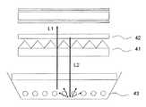
図4は従来の液晶表示装置の構成例を示す断面図である。
バックライトユニット33は、液晶パネル12の背面に光源ランプ22を設置し、この光源の光を透過照射するタイプの直下型方式のものと、液晶パネル32の側端部にランプを設置し、そこからの光を導光板内で多重反射させて液晶パネル32の背面から間接的に光を照射する導光板ライトガイド式(エッジライト式)に分類される。
光源ランプ22には、冷陰極管(CCFL)が一般的に用いられるが、それ以外にもRed(617nm)、Green(533nm)、Blue(451nm)のLEDをその輝度と色のバランスを考慮した順にライン状に並べた3波長タイプのLEDを用いても良い。FIG. 4 is a cross-sectional view showing a configuration example of a conventional liquid crystal display device.
The
A cold cathode fluorescent lamp (CCFL) is generally used for the
20インチ以上の大型液晶表示装置に関しては、薄型、視野角依存性の低さ、高輝度、低消費電力であることが求められ、液晶表示装置に搭載されるバックライトもそれに対応したものが要求されている。 Large liquid crystal display devices of 20 inches or more are required to be thin, have low viewing angle dependency, high brightness, and low power consumption, and the backlight mounted on the liquid crystal display device must also be compatible with it. Has been.
バックライトユニット33の光源手段23は、散乱反射層が内面に形成された筐体の内部に、略棒状をなす光源ランプ22が複数配列されてなるものであり、複数の光源ランプ22の出射側には、これらの光源ランプ22を覆うように拡散板21が設けられている。光源手段23から入射した光は拡散板21によって拡散された後、前記光学シート31に入射する。 The light source means 23 of the
光学シート31は、入射する光を拡散しムラをなくすための拡散シート18と、入射する光の指向性を制御するコントロールシート30と、前記光学シート31から出射した光のうち一方の偏光方向のみを透過し、他方の偏光の光を反射する反射型偏光分離シート13から構成される。 The
光学シート31のうち、コントロールシート30は、光源手段23から発せられ拡散板21によって拡散された光の指向性を液晶パネルの有効雄表示領域に方向付けるようにコントロールし、前記偏光分離シート13によって液晶パネル32で利用する偏光成分を持つ光のみを透過し、利用しない偏光の光は反射し再利用することによって、光の利用効率を高める働きをする。
上述のように、図4に示す構成において、反射型偏光分離シート42で反射した光は、プリズムシート41を透過して光源手段43まで戻り、この光源手段43の散乱反射層で偏光方向が乱れるように散乱反射することにより、再利用される。
しかし、光源手段には、拡散板以外にもさまざまなフィルムが使用されており、これらを光が透過するときにロスが生じてしまう問題がある。したがって、これまでの液晶表示装置では、光の利用効率を高めるために上記のような光学シートを用いたにもかかわらず、十分に光の利用効率を高めることができなかった。As described above, in the configuration shown in FIG. 4, the light reflected by the reflective
However, various films other than the diffusion plate are used for the light source means, and there is a problem that loss occurs when light passes through these films. Therefore, in the conventional liquid crystal display devices, although the above optical sheet is used to increase the light utilization efficiency, the light utilization efficiency cannot be sufficiently enhanced.
さらに、このようなバックライトユニットでは、光源手段23からの光を拡散するための拡散板が一枚では十分な拡散効果が得られず、複数枚の拡散板、あるいは拡散フィルムを用いることがある。この場合、厚みが増してしまうのみならず構造も煩雑となり、小型化への対応に対する阻害要因となってしまう。 Further, in such a backlight unit, a single diffusion plate for diffusing light from the light source means 23 cannot provide a sufficient diffusion effect, and a plurality of diffusion plates or diffusion films may be used. . In this case, not only the thickness is increased, but also the structure becomes complicated, which becomes an impediment to the reduction in size.
そこで本発明は、液晶パネルに対してその背面側から光を照射するバックライトユニットを備えた液晶表示装置において、光の利用効率を効果的に高めることを可能にする光学シートと、この光学シートを備えたバックライトユニットと、このバックライトユニットを備えた液晶表示装置を提供することを目的としている。 Accordingly, the present invention provides an optical sheet that can effectively increase the light use efficiency in a liquid crystal display device including a backlight unit that irradiates light from the back side of the liquid crystal panel, and the optical sheet. And a liquid crystal display device including the backlight unit.
上述の目的を達成するため、本発明の光学シートは、複数の単位レンズが配列されてなるレンズ部が出射面側に設けられると共に、前記単位レンズの焦点位置に対応した開口部を有する散乱反射層が入射面側に設けられ、入射する光のうち前記開口部を通過した光の指向性を前記レンズ部によってコントロールするコントロールシートと、前記コントロールシートの散乱反射層側に設けられ、前記光源から入射する光を拡散透過する光拡散層と、前記コントロールシートのレンズ部側に設けられ、前記レンズ部を透過する光のうち一方の偏光方向の光のみを透過し、他方の偏光方向の光は反射する反射型偏光分離シートとを備えていることを特徴とする。 In order to achieve the above-described object, the optical sheet of the present invention is provided with a lens portion in which a plurality of unit lenses are arranged on the exit surface side, and has a scattering reflection having an opening corresponding to the focal position of the unit lens. A layer is provided on the incident surface side, a control sheet that controls the directivity of light that has passed through the opening of incident light by the lens unit, and a scattering reflection layer side of the control sheet. A light diffusing layer that diffuses and transmits incident light and a lens portion side of the control sheet, and transmits only light in one polarization direction among the light transmitted through the lens portion, and light in the other polarization direction And a reflective polarization separation sheet for reflection.
また本発明バックライトユニットは、の光学シートと光源とを備え、前記光学シートは、複数の単位レンズが配列されてなるレンズ部が出射面側に設けられると共に、前記単位レンズの焦点位置に対応した開口部を有する散乱反射層が入射面側に設けられ、入射する光のうち前記開口部を通過した光の指向性を前記レンズ部によってコントロールするコントロールシートと、前記コントロールシートの散乱反射層側に設けられ、前記光源から入射する光を拡散透過する光拡散層と、前記コントロールシートのレンズ部側に設けられ、前記レンズ部を透過する光のうち一方の偏光方向の光のみを透過し、他方の偏光方向の光は反射する反射型偏光分離シートとを備えていることを特徴とする。 The backlight unit of the present invention includes an optical sheet and a light source. The optical sheet is provided with a lens portion in which a plurality of unit lenses are arranged on the exit surface side, and corresponds to a focal position of the unit lens. A control sheet for controlling the directivity of light that has passed through the opening of the incident light by the lens unit, and the scattering reflection layer side of the control sheet. A light diffusing layer that diffuses and transmits light incident from the light source, and is provided on the lens portion side of the control sheet, and transmits only light in one polarization direction among the light transmitted through the lens portion, The light of the other polarization direction is provided with the reflective polarization separation sheet | seat which reflects.
また本発明の液晶表示装置は、光学シートと光源とを備えたバックライトユニットと、前記バックライトユニットによって照射される液晶パネルとを備え、前記光学シートは、複数の単位レンズが配列されてなるレンズ部が出射面側に設けられると共に、前記単位レンズの焦点位置に対応した開口部を有する散乱反射層が入射面側に設けられ、入射する光のうち前記開口部を通過した光の指向性を前記レンズ部によってコントロールするコントロールシートと、前記コントロールシートの散乱反射層側に設けられ、前記光源から入射する光を拡散透過する光拡散層と、前記コントロールシートのレンズ部側に設けられ、前記レンズ部を透過する光のうち一方の偏光方向の光のみを透過し、他方の偏光方向の光は反射する反射型偏光分離シートとを備えていることを特徴とする。 The liquid crystal display device of the present invention includes a backlight unit including an optical sheet and a light source, and a liquid crystal panel irradiated by the backlight unit, and the optical sheet includes a plurality of unit lenses arranged. A lens portion is provided on the exit surface side, and a scattering reflection layer having an opening corresponding to the focal position of the unit lens is provided on the entrance surface side, and directivity of light that has passed through the opening portion of incident light A control sheet that is controlled by the lens unit, provided on the scattering reflection layer side of the control sheet, and provided on the lens unit side of the control sheet, a light diffusion layer that diffuses and transmits light incident from the light source, A reflective polarization separation sheet that transmits only light in one polarization direction and reflects light in the other polarization direction among light transmitted through the lens unit Characterized in that it comprises a.
本発明の光学シートによれば、光源からの入射光にコントロールシートで指向性を付与し、レンズ部を透過する光のうち一方の偏光光を反射型偏光分離シートで透過し、他方の偏光光を反射型偏光分離シートで反射することにより、この反射光を再度コントロールシートに送って再利用する構成により、単一の光学シートによって光源光の利用効率を向上することが可能となる。
したがって、このような光学シートを用いたバックライトユニット、および液晶表示装置では、単一の光学シートによって光源光の利用効率を向上することができ、輝度の向上、光源の小型、低廉化、消費電力の節約、光学系の簡素化、装置の小型化等を図ることが可能となる。According to the optical sheet of the present invention, directivity is imparted to the incident light from the light source by the control sheet, one polarized light of the light transmitted through the lens unit is transmitted by the reflective polarization separation sheet, and the other polarized light is transmitted. The reflected light is reflected by the reflection type polarization separation sheet, so that the reflected light is sent to the control sheet again and reused, so that the light source light utilization efficiency can be improved by a single optical sheet.
Therefore, in the backlight unit and the liquid crystal display device using such an optical sheet, the use efficiency of the light source light can be improved by a single optical sheet, and the luminance can be improved, the light source can be made smaller, cheaper, and consumed. It is possible to save power, simplify the optical system, reduce the size of the apparatus, and the like.
図1は本発明の実施の形態による液晶表示装置の構成例を示す概略断面図であり、図2は本発明の実施の形態による光学シートの構成例を示す概略断面図である。
また、図3は本実施の形態で用いる溶融押し出し法による光学シート製造方法の一例を示す概略説明図である。FIG. 1 is a schematic sectional view showing a configuration example of a liquid crystal display device according to an embodiment of the present invention, and FIG. 2 is a schematic sectional view showing a configuration example of an optical sheet according to the embodiment of the present invention.
FIG. 3 is a schematic explanatory view showing an example of an optical sheet manufacturing method by a melt extrusion method used in the present embodiment.
本実施の形態による光学シート31は、複数の単位レンズが配列されて構成されるレンズ部15が出射面内に設けられるととともに、単位レンズの焦点位置に対応した開口部を有する散乱反射層16が設けられ、コントロールシート30と、散乱反射層16側に設けられた光源からの光を拡散する拡散シート18と、コントロールシート30のレンズ部15側に設けられ、コントロールシート30から出射された光のうち、片方の偏光のみを透過し、他方の偏光の光を反射する反射型偏光分離シート13により構成される。
また、本実施の形態によるバックライトユニット33は、本発明の光学シート31と、前記光学シートに光を照射する光源手段23を備えている。
さらに、本実施の形態による液晶表示装置は、本実施の形態によるバックライトユニット33と、このバックライトユニットによって背面側から光が照射される液晶パネル12を備えている。The
The
Furthermore, the liquid crystal display device according to the present embodiment includes the
このように、光学シート31を備えたバックライトユニット33によって構成した液晶表示装置では、まず、光源手段23から照射された光が拡散シート18によって光の指向性が拡散され、前記拡散シート18により拡散された光が光指向性コントロールシート30に入射すると、この入射した光のうち散乱反射層16の開口部を通過した光はレンズ部15によって指向性をコントロールされ、前記コントロールシート30を出射した光は反射型偏光分離シート13に入射する。反射型偏光分離シート13に入射した光のうち、液晶パネルで用いられる一方の偏光をもつ光のみが透過し、他方の偏光の光は反射され、光指向性コントロールシート30を再度通過する。 In this way, in the liquid crystal display device constituted by the
なお、光指向性コントロールシート30の入射面側には散乱反射層16が設けられ、反射型偏光分離シート13で反射された光は散乱反射層16で散乱反射され、再度偏光分離シート13に入射することになる。
また、光指向性コントロールシート30と偏光分離シート13との間には、両者よりも低い屈折率を示す低屈折率材料からなる低屈折率材料層14を備えている。
本光学シート31と光拡散シート18との間には粘着層あるいは接着層17を介して積層一体型を構成する。この場合、開口部と光拡散層の間を粘着層、或いは接着層が埋める形となる場合、予期せぬ入射光の混入を引き起こす恐れがあり、設計通りの光学特性を発揮することが難しくなる。
従って、所望の光学特性を得るためには、開口部と光拡散層の間を空気層のような低屈折率層を介在させることが望ましく、そのために開口部とその周囲には明確な段差を設ける必要がある。In addition, the
Further, a low refractive
A laminated integrated type is formed between the
Therefore, in order to obtain the desired optical characteristics, it is desirable to interpose a low refractive index layer such as an air layer between the opening and the light diffusion layer. It is necessary to provide it.
以下、本実施の形態について個々の構成および動作を順次詳細に説明する。
まず、液晶表示装置は、図1に示すように、略長方形平板状をなすパネル本体12がその両面側を偏光板11で挟まれることによって構成された液晶パネル32と、この液晶パネル32の背面側に配置され、液晶パネル32に対してその背面側から光を照射するバックライトユニット33とを備えている。Hereinafter, the individual configurations and operations of the present embodiment will be sequentially described in detail.
First, as shown in FIG. 1, the liquid crystal display device includes a
また、バックライトユニット33は、後述する光学シート31と、この光学シート31に光を照射する光源手段23とを備えている。つまり、液晶パネル32の背面側には、光学シート31(後述する反射型偏光分離シート13、低屈折材料層14、光指向性コントロールシート30、粘着層17、光拡散シート18)、光源手段23が順次配置されているのである。
バックライトユニット33の光源手段23は、例えば空気の超微粒子が分散混入された白色のPETフィルムなどからなる散乱反射層が内面に形成された筐体の内部に、例えば冷陰極管(CCFL)などの略棒状をなす光源ランプ22が複数配列されることによって構成されている。Further, the
The light source means 23 of the
また、光源手段23において、複数の光源ランプ22の出射側には、これら光源ランプ22を覆うようにして、例えばフィラーが分散混入されたPMMA(ポリメチルメタクリレート)、PC(ポリカーボネート)、COP(シクロオレフィンポリマー)などからなる例えば厚み2mm程度の拡散板21が設けられている。そのため、光源手段23が光学シートに照射する光は、光源ランプ22の光が拡散板21によって拡散させられた光となる。 Further, in the light source means 23, on the emission side of the plurality of
バックライトユニット33の光学シート31は、図1及び図2に示すように、光源手段23から照射された光が入射する光拡散シート18と、光の指向性を制御する光指向性コントロールシート30と、この光指向性コントロールシート30から出射された光が入射する反射型偏光分離シート13と、これら光指向性コントロールシート30及び反射型偏光分離シート13を有効に機能させるために光指向性コントロールシート30と反射型偏光分離シート13との間に充填された低屈折材料層14とを備えている。 As shown in FIGS. 1 and 2, the
光指向性コントロールシート30は、シート本体における出射面側に、複数の単位レンズが配列されてなるレンズ部15が設けられるとともに、シート本体における入射面側に、単位レンズの焦点位置に対応した開口部を有する散乱反射層16が設けられることによって構成されている。 The light
レンズ部15の一例としては、例えば、略半円柱状をなす複数のシリンドリカルレンズ(単位レンズ)が略平行に配列されてなるレンチキュラーレンズ部や、略半球状をなす複数のマイクロレンズ(単位レンズ)がマトリックス状に配列されてなるマイクロレンズ部や、複数のシリンドリカルレンズ(単位レンズ)が略平行に配列された第1のレンズアレイと複数のシリンドリカルレンズ(単位レンズ)が略平行に配列された第2のレンズアレイとがそれらのシリンドリカルレンズの長さ方向を互いに交差させるように同一平面上に配置されてなるクロスレンチレンズ部などが挙げられる。レンズを構成する樹脂としては、熱可塑性樹脂であるCOPやPMMA、PCなどを用いる。 As an example of the
散乱反射層16は、例えば白色のTiO2微粒子が分散混入された透明樹脂などからなる。反射層を構成する顔料としては、TiO2の他にSiO2やBaSO4、Al2O3などを用いることもある。上記のような各種のレンズ部15に応じて、その単位レンズの焦点位置に対応した開口部を有している。例えば、レンズ部15が上記レンチキュラーレンズ部とされている場合には、散乱反射層16に形成される開口部がストライプ状となり、レンズ部15が上記マイクロレンズ部やクロスレンチレンズ部とされている場合には、散乱反射層16に形成される開口部がマトリックス状となる。なお、開口部の詳細な形状は、液晶表示装置としての液晶パネルに求められる視野角等に応じて適宜決定される。 The
図2に示すように、光源手段23から照射された光が光指向性コントロールシート30に入射すると、この入射する光のうち散乱反射層16に形成された開口部を通過した光LAが、その指向性を液晶パネルの有効表示領域に向けて方向付けられるようにコントロールされてから、反射型偏光分離シート13に向けて出射される。
これに対して、入射する光のうち散乱反射層16に形成された開口部を通過しない光LBは、散乱反射層16で反射されて光源手段23まで戻り、この光源手段23の散乱反射層16で偏光方向が乱れるように散乱反射されることにより、再利用される。As shown in FIG. 2, when the light emitted from the light source means 23 enters the light
On the other hand, light LB which does not pass through the opening formed in the
反射型偏光分離シート13は、光指向性コントロールシート30から出射された光のうち一方の偏光方向の直線偏光を透過するとともに他方の偏光方向の直線偏光を反射するように構成されている。なお、本実施形態では、反射型偏光分離シート13が、他方の偏光方向の直線偏光を散乱反射するものとなっている。
この反射型偏光分離シート13の一例としては、例えば、複屈折性多層膜からなるものや、コレステリック液晶層及び位相差板からなるものなどが挙げられる。The reflective
As an example of this reflection type
図2に示すように、光指向性コントロールシート30から出射された光が反射型偏光分離シート13に入射すると、この入射する光のうち液晶パネルで使用される一方の偏光方向の光L1(例えばp偏光の光)が、反射型偏光分離シート13を透過して液晶パネルに向けて出射される。
これに対して、入射する光のうち液晶パネルで使用されない他方の偏光方向の光L2は、反射型偏光分離シート13で反射されて光指向性コントロールシート30を再度透過することになる。As shown in FIG. 2, when the light emitted from the light
On the other hand, the light L2 having the other polarization direction that is not used in the liquid crystal panel among the incident light is reflected by the reflective
ここで、光指向性コントロールシート30の入射面側には散乱反射層16が設けられていることから、反射型偏光分離シート13で反射されて光指向性コントロールシート30を再度透過する光のうち、散乱反射層16に形成された開口部を通過しない光LXは、散乱反射層16で偏光方向が乱れるように散乱反射されて、反射型偏光分離シート13に向けて再度出射されることにより、再利用される。 Here, since the
低屈折材料層14は、光指向性コントロールシート30のレンズ部15及び反射型偏光分離シート13よりも低い屈折率を示す低屈折材料からなるものである。
この低屈折材料としては、例えば、もともと低い屈折率を示すアクリル系の樹脂や、空気あるいはシリカの超微粒子(大きさ10nm〜100nm)が分散混入された透明樹脂や、空気などが挙げられる。The low
Examples of the low-refractive material include an acrylic resin originally exhibiting a low refractive index, a transparent resin in which air or silica ultrafine particles (size: 10 nm to 100 nm) are dispersed and mixed, and air.
以上説明したような本実施の形態では、光源手段23からの光が光指向性コントロールシート30によって指向性をコントロールされてから反射型偏光分離シート13によって分離されてなる一方の偏光方向の光L1(液晶パネルで使用される例えばp偏光の光)を、バックライト33によって液晶パネルの背面に照射するようになっている。 In the present embodiment as described above, the light L1 in one polarization direction is formed by the light from the light source means 23 being controlled by the light
そして、反射型偏光分離シート13によって分離された他方の偏光方向の光L2(液晶パネルで使用されない例えばs偏光の光)のうち、光指向性コントロールシート30の散乱反射層16に形成された開口部を通過しない光を、ロスが大きく生じてしまう光源手段23にまで到達させることなく、この光指向性コントロールシート30の散乱反射層16で偏光方向が乱れるように散乱反射させて、反射型偏光分離シート13に向けて再度出射することにより、その再利用を図ることができる。 Of the light L2 in the other polarization direction separated by the reflective polarization separation sheet 13 (for example, s-polarized light not used in the liquid crystal panel), an opening formed in the
したがって、液晶表示装置のバックライトユニット33に上述したような光学シート31を設けたことによって得られる効果を存分に発揮することができ、光源手段23における光源ランプ22の光の利用効率を効果的に高めることができる。
つまり、従来と比較して、同じ電力を光源ランプ22に供給するのであれば、液晶パネルの明るさを増大させることができ、同じ液晶パネルの明るさを維持するのであれば、光源ランプ22に供給する電力を小さくすることができるのである。Therefore, the effect obtained by providing the
That is, the brightness of the liquid crystal panel can be increased if the same power is supplied to the
以下、光学シート31の具体的な例について説明する。
まず、レンズシート2は、はPET(ポリエチレンテレフタレート)、PC(ポリカーボネイト)、PP(ポリプロピレン)、COP(シクロオレフィンポリマー)などの樹脂を用いて、溶融押出し成形法により作製する。Hereinafter, a specific example of the
First, the
反射層1は、押出し時の基材の熱を用いて熱転写するのが望ましいが、特にこれに限定
するものではなく、適用可能である。The
最後に本実施の形態による光学シートを作成できる溶融押出し成形法による製造方法の例について説明する。
図3はこの溶融押出し成形法の概要を示している。図示のように、押し出し機5から送り出されたフィルム4は、成形ローラ6によって転写箔3と一体化される。
なお、押し出し機5としては、図示しない樹脂投入口となるホッパー、溶融混練しつつ押出すスクリュー、シート状に押出すためのT-ダイとからなるものが好適に用いられるが、特にこれに限定するものではなく、適用可能である。Finally, an example of a manufacturing method by a melt extrusion method that can produce an optical sheet according to the present embodiment will be described.
FIG. 3 shows an outline of this melt extrusion molding method. As shown in the figure, the film 4 fed from the extruder 5 is integrated with the transfer foil 3 by the forming roller 6.
The extruder 5 is preferably composed of a hopper serving as a resin inlet (not shown), a screw that is extruded while being melt-kneaded, and a T-die that is extruded into a sheet shape. It is not intended to be applied.
1……散乱反射層、2……光指向性コントロールシート、3……転写箔、4……フィルム、5……押し出し機、11……偏光板、12……液晶、13……偏光分離シート、14……低屈折率物質層、15……光指向性コントロールシート、16……散乱反射層、17……粘着層、18……拡散シート、21……拡散板、22……冷陰極管、23……光源手段、30……光指向性コントロールシート、31……光学シート、32……液晶パネル、33……バックライトユニット、41……プリズムシート、42……偏光分離シート、43……光源手段。
DESCRIPTION OF
Claims (21)
Translated fromJapanese前記コントロールシートの散乱反射層側に設けられ、前記光源から入射する光を拡散透過する光拡散層と、
前記コントロールシートのレンズ部側に設けられ、前記レンズ部を透過する光のうち一方の偏光方向の光のみを透過し、他方の偏光方向の光は反射する反射型偏光分離シートと、
を備えていることを特徴とする光学シート。A lens unit in which a plurality of unit lenses are arranged is provided on the exit surface side, and a scattering reflection layer having an opening corresponding to the focal position of the unit lens is provided on the entrance surface side, and the light out of the incident light A control sheet for controlling the directivity of the light that has passed through the opening by the lens unit;
A light diffusion layer that is provided on the scattering reflection layer side of the control sheet and diffuses and transmits light incident from the light source;
A reflective polarization separation sheet that is provided on the lens portion side of the control sheet and transmits only light in one polarization direction among light transmitted through the lens portion, and reflects light in the other polarization direction;
An optical sheet comprising:
複数の単位レンズが配列されてなるレンズ部が出射面側に設けられると共に、前記単位レンズの焦点位置に対応した開口部を有する散乱反射層が入射面側に設けられ、入射する光のうち前記開口部を通過した光の指向性を前記レンズ部によってコントロールするコントロールシートと、
前記コントロールシートの散乱反射層側に設けられ、前記光源から入射する光を拡散透過する光拡散層と、
前記コントロールシートのレンズ部側に設けられ、前記レンズ部を透過する光のうち一方の偏光方向の光のみを透過し、他方の偏光方向の光は反射する反射型偏光分離シートと、
を備えていることを特徴とするバックライトユニット。An optical sheet and a light source, the optical sheet,
A lens unit in which a plurality of unit lenses are arranged is provided on the exit surface side, and a scattering reflection layer having an opening corresponding to the focal position of the unit lens is provided on the entrance surface side, and the light out of the incident light A control sheet for controlling the directivity of the light that has passed through the opening by the lens unit;
A light diffusion layer that is provided on the scattering reflection layer side of the control sheet and diffuses and transmits light incident from the light source;
A reflective polarization separation sheet that is provided on the lens portion side of the control sheet and transmits only light in one polarization direction among light transmitted through the lens portion, and reflects light in the other polarization direction;
A backlight unit characterized by comprising:
複数の単位レンズが配列されてなるレンズ部が出射面側に設けられると共に、前記単位レンズの焦点位置に対応した開口部を有する散乱反射層が入射面側に設けられ、入射する光のうち前記開口部を通過した光の指向性を前記レンズ部によってコントロールするコントロールシートと、
前記コントロールシートの散乱反射層側に設けられ、前記光源から入射する光を拡散透過する光拡散層と、
前記コントロールシートのレンズ部側に設けられ、前記レンズ部を透過する光のうち一方の偏光方向の光のみを透過し、他方の偏光方向の光は反射する反射型偏光分離シートと、
を備えていることを特徴とする液晶表示装置。A backlight unit including an optical sheet and a light source, and a liquid crystal panel irradiated by the backlight unit, the optical sheet,
A lens unit in which a plurality of unit lenses are arranged is provided on the exit surface side, and a scattering reflection layer having an opening corresponding to the focal position of the unit lens is provided on the entrance surface side, and the light out of the incident light A control sheet for controlling the directivity of the light that has passed through the opening by the lens unit;
A light diffusion layer that is provided on the scattering reflection layer side of the control sheet and diffuses and transmits light incident from the light source;
A reflective polarization separation sheet that is provided on the lens portion side of the control sheet and transmits only light in one polarization direction among light transmitted through the lens portion, and reflects light in the other polarization direction;
A liquid crystal display device comprising:
16. The liquid crystal display device according to claim 15, wherein the reflective polarization separation sheet and the lens surface of the control sheet are laminated and integrated with each other through a low refractive index material.
Priority Applications (1)
| Application Number | Priority Date | Filing Date | Title |
|---|---|---|---|
| JP2006134813AJP2007304460A (en) | 2006-05-15 | 2006-05-15 | Optical sheet, backlight unit, and liquid crystal display device |
Applications Claiming Priority (1)
| Application Number | Priority Date | Filing Date | Title |
|---|---|---|---|
| JP2006134813AJP2007304460A (en) | 2006-05-15 | 2006-05-15 | Optical sheet, backlight unit, and liquid crystal display device |
Publications (1)
| Publication Number | Publication Date |
|---|---|
| JP2007304460Atrue JP2007304460A (en) | 2007-11-22 |
Family
ID=38838424
Family Applications (1)
| Application Number | Title | Priority Date | Filing Date |
|---|---|---|---|
| JP2006134813APendingJP2007304460A (en) | 2006-05-15 | 2006-05-15 | Optical sheet, backlight unit, and liquid crystal display device |
Country Status (1)
| Country | Link |
|---|---|
| JP (1) | JP2007304460A (en) |
Cited By (11)
| Publication number | Priority date | Publication date | Assignee | Title |
|---|---|---|---|---|
| WO2009047933A1 (en)* | 2007-10-09 | 2009-04-16 | Sharp Kabushiki Kaisha | Light control layer of backlight, backlight, liquid crystal display, and method of manufacturing light control layer of backlight |
| JP2009162843A (en)* | 2007-12-28 | 2009-07-23 | Toppan Printing Co Ltd | Double-sided lens sheet, optical sheet for display, backlight unit using the same, and display device |
| JP2009204781A (en)* | 2008-02-27 | 2009-09-10 | Toppan Printing Co Ltd | Lens sheet, optical sheet for display and backlight unit using the same, and display device |
| JP2009276616A (en)* | 2008-05-15 | 2009-11-26 | Dainippon Printing Co Ltd | Optical sheet, surface light source device, and transmission type display device |
| JP2011070118A (en)* | 2009-09-28 | 2011-04-07 | Dainippon Printing Co Ltd | Optical sheet, surface light source device, and transmission-type display device |
| EP2530515A3 (en)* | 2011-06-03 | 2012-12-19 | Innocom Technology (Shenzhen) Co., Ltd. | Optical film and method for manufacturing the same and liquid crystal display device using the same |
| DE102012210773A1 (en)* | 2012-06-25 | 2014-01-02 | Osram Gmbh | DEVICE FOR PRODUCING POLARIZED ELECTROMAGNETIC RADIATION AND PROJECTOR |
| KR101541279B1 (en)* | 2008-06-04 | 2015-08-03 | 삼성디스플레이 주식회사 | An optical film, a backlight unit having the optical film, and an LCD device having the backlight unit |
| US9477117B2 (en) | 2013-07-24 | 2016-10-25 | Samsung Display Co., Ltd. | Optical lens module and backlight unit |
| US10649274B2 (en) | 2009-04-15 | 2020-05-12 | 3M Innovative Properties Company | Optical construction and display system incorporating same |
| WO2023133762A1 (en)* | 2022-01-13 | 2023-07-20 | 厦门市芯颖显示科技有限公司 | Micro led display panel and fabricating method therefor |
- 2006
- 2006-05-15JPJP2006134813Apatent/JP2007304460A/enactivePending
Cited By (15)
| Publication number | Priority date | Publication date | Assignee | Title |
|---|---|---|---|---|
| WO2009047933A1 (en)* | 2007-10-09 | 2009-04-16 | Sharp Kabushiki Kaisha | Light control layer of backlight, backlight, liquid crystal display, and method of manufacturing light control layer of backlight |
| JP2009162843A (en)* | 2007-12-28 | 2009-07-23 | Toppan Printing Co Ltd | Double-sided lens sheet, optical sheet for display, backlight unit using the same, and display device |
| JP2009204781A (en)* | 2008-02-27 | 2009-09-10 | Toppan Printing Co Ltd | Lens sheet, optical sheet for display and backlight unit using the same, and display device |
| JP2009276616A (en)* | 2008-05-15 | 2009-11-26 | Dainippon Printing Co Ltd | Optical sheet, surface light source device, and transmission type display device |
| KR101541279B1 (en)* | 2008-06-04 | 2015-08-03 | 삼성디스플레이 주식회사 | An optical film, a backlight unit having the optical film, and an LCD device having the backlight unit |
| US10649274B2 (en) | 2009-04-15 | 2020-05-12 | 3M Innovative Properties Company | Optical construction and display system incorporating same |
| US11435616B2 (en) | 2009-04-15 | 2022-09-06 | 3M Innovative Properties Company | Optical construction and display system incorporating same |
| JP2011070118A (en)* | 2009-09-28 | 2011-04-07 | Dainippon Printing Co Ltd | Optical sheet, surface light source device, and transmission-type display device |
| EP2530515A3 (en)* | 2011-06-03 | 2012-12-19 | Innocom Technology (Shenzhen) Co., Ltd. | Optical film and method for manufacturing the same and liquid crystal display device using the same |
| US8730432B2 (en) | 2011-06-03 | 2014-05-20 | Innocom Technology (SHENZHEN) Co. Ltd. | Optical film and method for manufacturing the same and liquid crystal display device using the same |
| DE102012210773A1 (en)* | 2012-06-25 | 2014-01-02 | Osram Gmbh | DEVICE FOR PRODUCING POLARIZED ELECTROMAGNETIC RADIATION AND PROJECTOR |
| US9341881B2 (en) | 2012-06-25 | 2016-05-17 | Osram Gmbh | Device for generating polarized electromagnetic radiation and projector |
| DE102012210773B4 (en) | 2012-06-25 | 2022-10-06 | Osram Gmbh | Device for generating polarized electromagnetic radiation and projector |
| US9477117B2 (en) | 2013-07-24 | 2016-10-25 | Samsung Display Co., Ltd. | Optical lens module and backlight unit |
| WO2023133762A1 (en)* | 2022-01-13 | 2023-07-20 | 厦门市芯颖显示科技有限公司 | Micro led display panel and fabricating method therefor |
Similar Documents
| Publication | Publication Date | Title |
|---|---|---|
| JP2007304460A (en) | Optical sheet, backlight unit, and liquid crystal display device | |
| CN102224448B (en) | Semi-specular hollow backlight with gradient extraction | |
| JP5792464B2 (en) | BACKLIGHT HAVING SELECTIVE OUTPUT LIGHT DISTRIBUTION, DISPLAY SYSTEM USING SAME, AND METHOD FOR FORMING BACKLIGHT | |
| CN101487948B (en) | Optical sheet, and backlight unit and display using the same | |
| JP5071675B2 (en) | Illumination device and display device | |
| CN102313165A (en) | Lighting unit and display provided with the same | |
| JP2009187904A (en) | Light source unit, backlight unit and display device | |
| JP2010118240A (en) | Optical member, backlight unit, and display device | |
| US8118469B2 (en) | Surface illuminating device and image display apparatus | |
| WO2010095305A1 (en) | Illuminating device, surface light source, and liquid crystal display device | |
| JP2010072131A (en) | Light diffusion plate, optical sheet, backlight unit and display apparatus | |
| JP5098520B2 (en) | Light diffusing plate, backlight unit for display, display device | |
| JP5104459B2 (en) | Optical member and backlight unit and display using it | |
| WO2010001653A1 (en) | Light guide unit, planar light source device and liquid crystal display device | |
| KR102047232B1 (en) | Diffusing light guide film, backlight unit, and liquid crystal display device having thereof | |
| KR102591781B1 (en) | Display appartus | |
| JP2006330032A (en) | Optical sheet and backlight unit and display using the same | |
| JP2007256748A (en) | Optical sheet and backlight unit for display and image display | |
| JP2010032868A (en) | Lens sheet, display optical sheet, and illumination device, electronic signboard, back light unit and display all using this optical sheet | |
| WO2012002183A1 (en) | Liquid crystal display device and multilayer optical member | |
| JP5070891B2 (en) | Optical sheet and backlight unit and display using the same | |
| JP2012145951A (en) | Liquid crystal display device | |
| KR101560235B1 (en) | Backlight unit and liquid crystal display using the same | |
| JP2006030537A (en) | Optical sheet, backlight unit, and liquid crystal display device | |
| JP2009237475A (en) | Optical sheet, back light unit using the same, and display |