JP2007304236A - Liquid crystal display - Google Patents
Liquid crystal displayDownload PDFInfo
- Publication number
- JP2007304236A JP2007304236AJP2006131090AJP2006131090AJP2007304236AJP 2007304236 AJP2007304236 AJP 2007304236AJP 2006131090 AJP2006131090 AJP 2006131090AJP 2006131090 AJP2006131090 AJP 2006131090AJP 2007304236 AJP2007304236 AJP 2007304236A
- Authority
- JP
- Japan
- Prior art keywords
- liquid crystal
- stripe
- phase difference
- crystal panel
- stripe portion
- Prior art date
- Legal status (The legal status is an assumption and is not a legal conclusion. Google has not performed a legal analysis and makes no representation as to the accuracy of the status listed.)
- Granted
Links
Images


Landscapes
- Liquid Crystal (AREA)
- Devices For Indicating Variable Information By Combining Individual Elements (AREA)
- Polarising Elements (AREA)
Abstract
Translated fromJapaneseDescription
Translated fromJapanese本発明は、液晶表示装置に関し、特に、1つの液晶パネル上で2画面表示が可能な液晶表示装置に関する。 The present invention relates to a liquid crystal display device, and more particularly to a liquid crystal display device capable of displaying two screens on one liquid crystal panel.
従来より、テレビ受像機や情報機器等に搭載される表示装置として、表示用の液晶パネルを用いた液晶表示装置が知られている。この液晶表示装置に関しては、近年の情報機器の多様化に伴い、通常の1画面表示のみならず、1つの液晶パネル上で異なる2つの表示画像を2人の観察者が個別に視認できる2画面表示や、立体視を可能にする3次元表示等の多用な表示モードの実現が求められている。 2. Description of the Related Art Conventionally, a liquid crystal display device using a display liquid crystal panel is known as a display device mounted on a television receiver, information equipment, or the like. With respect to this liquid crystal display device, with the recent diversification of information devices, not only a normal one-screen display but also two screens on which two observers can visually recognize two different display images on one liquid crystal panel. Realization of various display modes such as display and three-dimensional display enabling stereoscopic viewing is required.
なお、本願に関連する技術文献としては、以下の特許文献が挙げられる。
しかしながら、2画面表示や3次元表示等の表示モードを有する液晶表示装置の開発は未だに不充分なものであり、さらなる進展が求められていた。また、2画面表示や3次元表示等の異なる表示モードを任意に切り替えることが可能な液晶表示装置についても、さらなる開発の要望があった。 However, development of a liquid crystal display device having a display mode such as two-screen display or three-dimensional display is still insufficient, and further progress has been demanded. There has also been a demand for further development of a liquid crystal display device that can arbitrarily switch between different display modes such as two-screen display and three-dimensional display.
本発明の液晶表示装置は、上記課題に鑑みて為されたものであり、光源と、光源に対向する偏光板と、偏光板上に配置され、第1の位相差もしくは第2の位相差が付与される第1のストライプ部及び第2のストライプ部からなる偏光制御液晶素子と、偏光制御液晶素子上で第1及び第2のストライプ部と平行に配置された複数のレンズ部と、第3の位相差を有した第3のストライプ部及び第4の位相差を有した第4のストライプ部が第1及び第2のストライプ部と直交して交互に配置された位相差板と、走査線及び表示信号線に接続された複数の表示画素が配置された液晶パネルと、第3及び第4のストライプ部のピッチに応じて走査線毎に表示信号線に印加される表示信号の極性を反転する制御回路と、を備えることを特徴とする。 The liquid crystal display device of the present invention has been made in view of the above problems, and is disposed on a light source, a polarizing plate facing the light source, and the polarizing plate, and has a first phase difference or a second phase difference. A polarization control liquid crystal element composed of a first stripe part and a second stripe part to be applied; a plurality of lens parts arranged in parallel with the first and second stripe parts on the polarization control liquid crystal element; A retardation plate in which a third stripe portion having a phase difference of 4 and a fourth stripe portion having a fourth phase difference are alternately arranged perpendicular to the first and second stripe portions, and a scanning line And the polarity of the display signal applied to the display signal line for each scanning line according to the pitch of the liquid crystal panel in which a plurality of display pixels connected to the display signal line are arranged and the third and fourth stripe portions And a control circuit.
本発明の液晶表示装置によれば、1つの液晶パネル上で異なる2つの表示画像を2人の観察者が個別に視認できる2画面表示が実現される。また、2画面表示において液晶パネルを水平ライン反転駆動する際に、表示品位の劣化を抑止することができる。 According to the liquid crystal display device of the present invention, a two-screen display is realized in which two observers can visually recognize two different display images on one liquid crystal panel. Further, when the liquid crystal panel is driven in the horizontal line inversion in the two-screen display, it is possible to suppress display quality deterioration.
さらに、上記2次元の2画面表示のみならず、2次元の1画面表示及び3次元の1画面表示の各表示モードを1つの液晶表示装置で任意に切り替えることが可能となる。 Further, not only the above-described two-dimensional two-screen display but also two display modes of two-dimensional one-screen display and three-dimensional one-screen display can be arbitrarily switched by one liquid crystal display device.
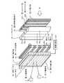
次に、本発明の第1の実施形態に係る液晶表示装置について図面を参照して説明する。図1は、本実施形態に係る液晶表示装置を模式的に説明する斜視図である。また、図2は、図1のX−X線に沿った断面図である。また、図3は、後述する図2の偏光制御液晶素子20を説明する平面図である。 Next, a liquid crystal display device according to a first embodiment of the present invention will be described with reference to the drawings. FIG. 1 is a perspective view schematically illustrating the liquid crystal display device according to the present embodiment. 2 is a cross-sectional view taken along line XX in FIG. FIG. 3 is a plan view for explaining the polarization control
図1及び図2に示すように、光源BLと対向して、その光(偏光されていない光)から直線偏光を抽出する第1の偏光板11が配置されている。光源BLと対向しない側の第1の偏光板11上には、第1の偏光板11により抽出された直線偏光の偏光軸の角度(直線偏光の進行方向と直交する平面における偏光軸の角度)を、所定の光学的位相差(以降、単に位相差と略称する)により制御する偏光制御液晶素子20が配置されている。 As shown in FIGS. 1 and 2, a first polarizing
偏光制御液晶素子20は、ガラス等の第1の透明基板21、第2の透明基板22及びシール23によって封止された液晶層LCからなる。液晶層LCは、特に限定されないが、ここでは一例として、電界制御複屈折(ECB; Electrically Controlled Birefringence)モードにより駆動するものとする。 The polarization control
第1の透明基板21上には、ITO(Indium Tin Oxide)等の透明金属からなる複数の第1の透明電極24が配置されている。第1の透明電極24は、図3のようにストライプ状に形成されており、互いに絶縁されている。また、第2の透明基板22上には、共通電位が供給される共通電極として、ITO等の透明金属からなる第2の透明電極25が配置されている。 A plurality of first
この偏光制御液晶素子20の液晶層LCは、複数の第1のストライプ部20A及び第2のストライプ部20Bに区分されている。第1のストライプ部20A及び第2のストライプ部20Bでは、第1の透明電極24への印加電圧を制御することにより、各液晶層LCに第1の位相差Φ1もしくは第2の位相差Φ2が付与される。第1の透明電極24へ電圧が印加される場合の位相差を第1の位相差Φ1とし、電圧が印加されない場合の位相差を第2の位相差Φ2とする。The liquid crystal layer LC of the polarization control
ここで、偏光制御液晶素子20に入射する直線偏光の波長をλとし、Rを任意の位相差とすると、第1の位相差Φ1はRであり、入射する直線偏光の偏光軸の角度を位相差Rに応じて回転させるものである。また、第2の位相差Φ2はR+λ/2であり、入射する直線偏光の偏光軸の角度を位相差R+λ/2に応じて回転させるものである。Here, when the wavelength of the linearly polarized light incident on the polarization control
さらに、第1の偏光板11と対向しない側の偏光制御液晶素子20上には、第1及び第2のストライプ部20A,20Bの長手方向に沿って平行に凸面が連続する複数のレンズ部30aが並ぶレンチキュラーレンズ30が配置されている。1つのレンズ部30aは、1対の第1のストライプ部20A及び第2のストライプ部20Bに対応して、これを覆うように配置されている。 Further, on the polarization control
これらのレンズ部30aは、第1及び第2のストライプ部20A,20Bから出射された直線偏光を、第1及び第2のストライプ部20A,20B毎に第1の観察者Aに向かう方向、もしくは第2の観察者Bに向かう方向に屈折させる。なお、第1の観察者A及び第2の観察者Bの存在する各領域は、第1及び第2のストライプ部20A,20Bの長手方向に沿って平行な線分によって区分される。 These
偏光制御液晶素子20と対向しない側のレンチキュラーレンズ30上には、第1の位相差板40が配置されている。第1の位相差板40には、複数の第3のストライプ部40A及び第4のストライプ部40Bが交互に配置されている。第3及び第4のストライプ部40A,40Bは、偏光制御液晶素子20の第1及び第2のストライプ部20A,20Bの長手方向と直交するように配置されている。 A
第3のストライプ部40Aには第3の位相差Φ3が付与され、第4のストライプ部40Bには第4の位相差Φ4が付与されている。第3の位相差Φ3は、0もしくはλ、もしくはそれらに近似した位相差であり、入射する直線偏光の偏光軸の角度を変化させないか、もしくは僅かに変化させるものである。また、第4の位相差Φ4はλ/2もしくはそれに近似した位相差であり、入射する直線偏光の偏光軸の角度を約90度回転させるものである。A third phase difference Φ3 is applied to the
また、第3のストライプ部40A及び第4のストライプ部40Bの各ピッチは、後述する液晶パネル50を構成する画素の垂直方向のピッチPと同一もしくは略同一である。この第1の位相差板40は、特に限定されないが、例えば、基材上に位相差を有した層をストライプ状にパターニングすることにより形成される。 The pitches of the
レンチキュラーレンズ30と対向しない側の第1の位相差板40上には、複数の画素50Pを有し第1の表示画像および第2の表示画像を提供する表示用の液晶パネル(以降、「液晶パネル」と略称する)50が配置されている。液晶パネル50は、ガラス等の第3の透明基板51、第4の透明基板52及びシール53によって封止された液晶層LCからなる。液晶パネル50の液晶層LCは、特に限定されないが、例えば、電界制御複屈折モードにより駆動する。 On the first
第3の透明基板51上には、ITO等の透明金属からなる複数の第3の透明電極54が配置されている。第3の透明電極54は、互いに絶縁され、マトリクス状に配置されている。また、第4の透明基板52上には、共通電位が供給される共通電極として、ITO等の透明金属からなる第4の透明電極55が配置されている。 A plurality of third
ここで、上記構成の画素50Pの等価回路図を図4に示す。図4に示すように、画素50Pは、画素選択信号が供給される走査線GLと、表示信号が供給される表示信号線DLとに囲まれる領域に配置されている。第3の透明電極54には、トランジスタTrを介して表示信号線DLから表示信号が印加される。 Here, an equivalent circuit diagram of the
さらに、液晶パネル50は、第2の偏光板12及び第3の偏光板13によって挟まれている。第2の偏光板12は第1の偏光板11と同一の偏光軸の角度を有している。また、第3の偏光板13は、第2の偏光板12に対してクロスニコル配置(偏光軸の角度が互いに直交する配置)されている。なお、液晶パネル50の画素50Pの垂直方向のピッチPは、上記第1の位相差板40の第3及び第4のストライプ部40A,40Bのピッチと同一もしくは略同一である。 Further, the
また、図5のように第1の偏光板11と対向する側の偏光制御液晶素子20上には、第2の位相差板42が配置されてもよい。この第2の位相差板42の位相差は、偏光制御液晶素子20の第1の位相差Φ1と同じ位相差Rである。以降、本実施形態ではR=λ/4として説明を行う。Further, a second retardation plate 42 may be disposed on the polarization control
さらに、本実施形態では、図2に示すように、第3の透明電極54に表示信号線DLを介して制御回路CNTが接続されている。この制御回路CNTは、図4の1つの走査線GLに接続されて水平方向に連なる一群の画素50P(以降、「液晶パネル50の行」と略称する)を単位として、表示信号の極性を反転する水平ライン反転駆動を行う。さらに、この制御回路CNTは、必要に応じて、液晶パネル50の連続する複数の行を単位として水平ライン反転駆動を行うように表示信号を制御する。 Furthermore, in the present embodiment, as shown in FIG. 2, the control circuit CNT is connected to the third
次に、本実施形態の液晶表示装置の動作について図面を参照して説明する。図5は、本実施形態の液晶表示装置の動作を説明する概念図である。 Next, the operation of the liquid crystal display device of this embodiment will be described with reference to the drawings. FIG. 5 is a conceptual diagram illustrating the operation of the liquid crystal display device of the present embodiment.
図5に示すように、最初に、第1の偏光板11により光源BLの光(偏光されていない光)から直線偏光が抽出される。この直線偏光は、第2の位相差板42に入射し、その偏光軸の角度が位相差Rに応じて回転して(R=λ/4の場合は円偏光となって)、偏光制御液晶素子20へ入射する。 As shown in FIG. 5, first, linearly polarized light is extracted from the light of the light source BL (unpolarized light) by the first
ここで、偏光制御液晶素子20の第1のストライプ部20Aへ入射した光は、第1の位相差Φ1即ちRにより、入射前の偏光軸の角度を保ったまま直線偏光となって出射される。一方、第2のストライプ部20Bへ入射した光は、第2の位相差Φ2即ちR+λ/2により、偏光軸の角度が入射前に比して約90度回転した直線偏光となって出射される。この直線偏光の偏光軸の角度は、第1及び第2の偏光板11,12の偏光軸と直交する角度となる。なお、このとき偏光制御液晶素子20内で生じる複屈折による不要な位相差が除去される。Here, the light incident on the
次に、第1のストライプ部20A及び第2のストライプ部20Bから出射された上記偏光軸の異なる2種類の直線偏光は、レンチキュラーレンズ30を透過する。これにより、第1のストライプ部20A及び第2のストライプ部20Bから出射された直線偏光は、それぞれ、第1の観察者Aに向かう方向、及び第2の観察者Bに向かう方向に屈折されると共に、第1の位相差板40に入射する。 Next, the two types of linearly polarized light having different polarization axes emitted from the
ここで、第1の位相差板40の第3のストライプ部40Aを透過する上記2種類の直線偏光は、第3の位相差Φ3により、そのままの偏光軸の角度を保ちながら第2の偏光板12へ入射する。このとき、上記2種類の直線偏光のうち、偏光制御液晶素子20の第1のストライプ部20Aを透過した第1の観察者Aに向かう直線偏光は、その偏光軸の角度が第2の偏光板12の偏光軸と一致するため、この第2の偏光板12を透過して液晶パネル50に入射する。一方、偏光制御液晶素子20の第2のストライプ部20Bを透過した第2の観察者Bに向かう直線偏光は、その偏光軸の角度が第2の偏光板12の偏光軸と直交するため、この第2の偏光板12を透過しない。即ち、第3のストライプ部40Aを透過する光は、第1の観察者Aの方向のみに向かう。Here, the two types of linearly polarized light transmitted through the
また、第1の位相差板40の第4のストライプ部40Bを透過する上記2種類の直線偏光は、第4の位相差Φ4により、その偏光軸が90度回転して第2の偏光板12へ入射する。このとき、上記2種類の直線偏光のうち、偏光制御液晶素子20の第1のストライプ部20Aを透過して第1の観察者Aに向かう直線偏光は、その偏光軸の角度が第2の偏光板12の偏光軸と直交するため、この第2の偏光板12を透過しない。一方、第2のストライプ部20Bを透過して第2の観察者Bに向かう直線偏光は、その偏光軸の角度が第2の偏光板12の偏光軸と一致するため、この第2の偏光板12を透過して液晶パネル50に入射する。即ち、第4のストライプ部40Bを透過する光は、第2の観察者Bの方向のみに向かう。Further, the two types of linearly polarized light transmitted through the first
このとき、液晶パネル50の各行のうち、第1の位相差板40の第3のストライプ部40Aに対応する行の画素50Pには、第1の表示画像に応じた表示信号が供給される。また、液晶パネル50の各行のうち、第4のストライプ部40Bに対応する行の画素50Pには、第2の表示画像に応じた表示信号が供給される。 At this time, a display signal corresponding to the first display image is supplied to the
そして、第1の位相差板40の第3のストライプ部40Aから第1の観察者Aの方向のみに向かう直線偏光は、その第3のストライプ部40Aに対応した液晶パネル50の行の画素50Pを通過し、第3の偏光板13を介して、第1の表示画像のみを第1の観察者Aのみに視認させる。 Then, the linearly polarized light directed only from the
また、第4のストライプ部40Bから第2の観察者Bの方向のみに向かう直線偏光は、その第4のストライプ部40Bに対応した液晶パネル50の行の画素50Pを通り、第3の偏光板13を介して、第2の表示画像のみを第2の観察者Bのみに視認させる。こうして、1つの液晶パネル50上で、異なる2つの表示画像を2人の観察者が個別に視認できる2画面表示が実現される。 Further, the linearly polarized light directed only from the
上記2画面表示の際、液晶パネル50の各行の画素50Pは、いわゆる焼き付きにより生じる残像現象等を抑止するため、制御回路CNTにより水平ライン反転駆動される。次に、その水平ライン反転駆動の様子について図面を参照して説明する。図6は、本実施形態に係る液晶表示装置の第1の位相差板40を説明する斜視図であり、図1及び図2に示したものと同様の液晶パネル50及び第1の位相差板40を示している。また、図7は、液晶パネル50の各行の表示信号と第1の位相差板40の第3及び第4のストライプ部40A,40Bとの関係を説明する図である。 During the above-described two-screen display, the
制御回路CNTは、液晶パネル50の1行毎に、即ち1つの走査線GL毎に、表示信号の極性を反転する。図6及び図7では反転する極性の一方を「+」で表し、他方の極性を「−」で表している。また、液晶パネル50の各行を、選択されるn行目の走査線GLの順に表している。 The control circuit CNT inverts the polarity of the display signal for each row of the
このとき、極性が「+」の表示信号が供給される液晶パネル50の行に対応する第1の位相差板40の第3のストライプ部40A及び第4のストライプ部40Bの行数は共に等しい。同様に、極性が「−」の表示信号が供給される液晶パネル50の行に対応する第1の位相差板40の第3のストライプ部40A及び第4のストライプ部40Bの行数は共に等しい。 At this time, the number of rows of the
ところで、通常の水平ライン反転駆動では、表示信号の極性の違いに応じて液晶パネル50の各行の画素50Pの輝度にばらつきが生じ、フリッカとなって表示品位が劣化することが知られている。 By the way, it is known that in normal horizontal line inversion driving, the luminance of the
これに対して本発明では、一方の極性の表示信号が供給される液晶パネル50の行に対応する第1の位相差板40の第3のストライプ部40A及び第4のストライプ部40Bの行数が等しい。そのため、表示信号の極性の違いに応じて液晶パネル50の各行の輝度にばらつきが生じても、第3のストライプ部40A及び第4のストライプ部40Bから出射される直線偏光は、それぞれ、各極性の表示信号が供給される液晶パネル50の行に平均的に入射する。結果として、上記のような表示品位の劣化を抑止することができる。 On the other hand, in the present invention, the number of rows of the
なお、制御回路CNTによる水平ライン反転駆動は上記に限定されず、次に示す第2の実施形態のように行われてもよい。図8は、本発明の第2の実施形態に係る液晶表示装置の第1の位相差板を説明する斜視図である。本実施形態では、図8の第1の位相差板70以外の構成は第1の実施形態と同様である。また、図9は、液晶パネル50の各行の表示信号と第1の位相差板70の第3及び第4のストライプ部70A,70Bとの関係を説明する図である。 The horizontal line inversion driving by the control circuit CNT is not limited to the above, and may be performed as in the second embodiment shown below. FIG. 8 is a perspective view for explaining the first retardation plate of the liquid crystal display device according to the second embodiment of the present invention. In the present embodiment, the configuration other than the
図8に示すように、第1の位相差板70の第3のストライプ部70A及び第4のストライプ部70Bは、それぞれ、液晶パネル50の画素50PのピッチPの奇数倍(3以上)と同一もしくは略同一のピッチを有して形成されている。本実施形態では一例として上記奇数が3である場合を示す。そして、図8及び図9に示すように、制御回路CNTは、液晶パネル50の連続する偶数個の行毎に、即ち連続する偶数個の走査線GL毎に、表示信号の極性を反転する。本実施形態では一例として上記偶数が4である場合を示す。 As shown in FIG. 8, the
この場合においても、一方の極性の表示信号が供給される液晶パネル50の行に対応する第1の位相差板70の第3のストライプ部70A及び第4のストライプ部70Bの行数が等しい。従って、第3のストライプ部70A及び第4のストライプ部70Bから出射される直線偏光は、それぞれ、各極性の表示信号が供給される液晶パネル50の行に平均的に入射する。結果として、上記表示品位の劣化を抑止することができる。 Even in this case, the number of rows of the
さらに、制御回路CNTによる水平ライン反転駆動は上記実施形態に限定されず、次に示す第3の実施形態のように行われてもよい。図10は、本発明の第3の実施形態に係る液晶表示装置の第1の位相差板を説明する斜視図である。本実施形態では、図10の第1の位相差板80以外の構成は第1の実施形態と同様である。また、図11は、液晶パネル50の各行の表示信号と第1の位相差板80の第3及び第4のストライプ部80A,80Bとの関係を説明する図である。 Further, the horizontal line inversion driving by the control circuit CNT is not limited to the above embodiment, and may be performed as in the following third embodiment. FIG. 10 is a perspective view illustrating a first retardation plate of a liquid crystal display device according to the third embodiment of the present invention. In the present embodiment, the configuration other than the
図10に示すように、第1の位相差板80の第3のストライプ部80A及び第4のストライプ部80Bは、それぞれ、液晶パネル50の画素50PのピッチPの偶数倍と同一もしくは略同一のピッチを有して形成されている。本実施形態では一例として上記偶数が2である場合を示す。そして、図10及び図11に示すように、制御回路CNTは、液晶パネル50の連続する奇数個の行毎に、即ち連続する奇数個の走査線GL毎に、表示信号の極性を反転する。本実施形態では上記奇数が1である場合を示す。 As shown in FIG. 10, the
この場合においても、一方の極性の表示信号が供給される液晶パネル50の行に対応する第1の位相差板80の第3のストライプ部80A及び第4のストライプ部80Bの行数が等しい。従って、第3のストライプ部80A及び第4のストライプ部80Bから出射される直線偏光は、それぞれ、各極性の表示信号が供給される液晶パネル50の行に平均的に入射する。結果として、上記表示品位の劣化を抑止することができる。 Also in this case, the number of rows of the
なお、上述した第1乃至第3の実施形態では、必要に応じて、偏光制御液晶素子20に対するレンチキュラーレンズ30の配置位置を調節することにより、偏光制御液晶素子20の第1及び第2のストライプ部20A,20Bから出射された直線偏光の進行方向を任意に変化させることができる。 In the first to third embodiments described above, the first and second stripes of the polarization control
例えば、偏光制御液晶素子20の第1及び第2のストライプ部20A,20Bから出射された直線偏光が屈折される方向を、1人の観察者の左眼及び右眼の各方向に合わせてもよい。この場合、液晶パネル50の各行に、交互に立体視用の2つの表示画像を表示すれば、3次元の1画面表示モードとなる。 For example, the direction in which the linearly polarized light emitted from the first and
また、必要に応じて、第1及び第2のストライプ部20A,20Bの全てが同一の位相差となるように第1の透明電極24への電圧印加の有無を制御してもよい。この場合、直線偏光が一方の方向のみに進行し、1人の観察者のみによる視認が行われる。 Further, if necessary, the presence or absence of voltage application to the first
即ち、2次元の2画面表示、2次元の1画面表示、及び3次元の1画面表示の各表示モードを、1つの液晶表示装置で任意に切り替えることが可能となる。 That is, each display mode of two-dimensional two-screen display, two-dimensional one-screen display, and three-dimensional one-screen display can be arbitrarily switched with one liquid crystal display device.
また、上述した第1乃至第3の実施形態では、偏光制御液晶素子20の液晶層LCは電界制御複屈折モードにより駆動するものとしたが、本発明はこれに限定されない。即ち、上記と同等の効果を奏する水平ライン反転駆動が行われるものであれば、液晶層LCは上記以外のモードにより駆動されるものでであってもよい。例えば、図示しないが、液晶層LCは、いわゆるVA(Vertically Aligned)モードにより駆動されるものであってもよい。この場合、第2の位相差板42の替わりに第3の位相差板が配置され、レンチキュラーレンズ30と液晶パネル50との間に第4の位相差板が配置される。第3の位相差板及び第4の位相差板の位相差は同一であり、例えばλ/4である。 In the first to third embodiments described above, the liquid crystal layer LC of the polarization control
11 第1の偏光板 12 第2の偏光板 13 第3の偏光板
20 偏光制御液晶素子 20A 第1のストライプ部
20B 第2のストライプ部 21 第1の透明基板
22 第2の透明基板 23,53 シール 24 第1の透明電極
25 第2の透明電極 30 レンチキュラーレンズ 30a レンズ部
40,70,80 第1の位相差板
40A,70A,80A 第3のストライプ部
40B,70B,80B 第4のストライプ部
42 第2の位相差板
50 液晶パネル 51 第3の透明基板 52 第4の透明基板
54 第3の透明電極 55 第4の透明電極
BL 光源 CNT 制御回路 LC 液晶層
GL 走査線 DL 表示信号線DESCRIPTION OF
Claims (3)
Translated fromJapanese前記光源に対向する偏光板と、
前記偏光板上に配置され、第1の位相差もしくは第2の位相差が付与される第1のストライプ部及び第2のストライプ部からなる偏光制御液晶素子と、
前記偏光制御液晶素子上で前記第1及び第2のストライプ部と平行に配置された複数のレンズ部と、
第3の位相差を有した第3のストライプ部及び第4の位相差を有した第4のストライプ部が前記第1及び第2のストライプ部と直交して交互に配置された位相差板と、
走査線及び表示信号線に接続された複数の表示画素が配置された液晶パネルと、
前記第3及び第4のストライプ部のピッチに応じて前記走査線毎に前記表示信号線に印加される表示信号の極性を反転する制御回路と、を備えることを特徴とする液晶表示装置。A light source;
A polarizing plate facing the light source;
A polarization control liquid crystal element that is arranged on the polarizing plate and includes a first stripe portion and a second stripe portion to which a first phase difference or a second phase difference is applied;
A plurality of lens portions arranged in parallel with the first and second stripe portions on the polarization control liquid crystal element;
A retardation plate in which a third stripe portion having a third phase difference and a fourth stripe portion having a fourth phase difference are alternately arranged perpendicular to the first and second stripe portions; ,
A liquid crystal panel in which a plurality of display pixels connected to scanning lines and display signal lines are arranged;
And a control circuit for inverting the polarity of a display signal applied to the display signal line for each scanning line in accordance with the pitch of the third and fourth stripe portions.
前記制御回路は、連続する偶数個の前記走査線毎に、前記表示信号の極性を反転することを特徴とする請求項1記載の液晶表示装置。The third stripe portion and the fourth stripe portion of the retardation film have a pitch substantially equal to an odd multiple of the pitch of the display pixels of the liquid crystal panel,
The liquid crystal display device according to claim 1, wherein the control circuit inverts the polarity of the display signal for every even number of the scanning lines.
前記制御回路は、1つの前記走査線毎に、もしくは連続する奇数個の前記走査線毎に前記表示信号の極性を反転すること特徴とする請求項1記載の液晶表示装置。The third stripe portion and the fourth stripe portion of the retardation plate have a pitch substantially equal to an even multiple of the pitch of the display pixels of the liquid crystal panel,
The liquid crystal display device according to claim 1, wherein the control circuit inverts the polarity of the display signal for each one of the scanning lines or for every odd number of consecutive scanning lines.
Priority Applications (1)
| Application Number | Priority Date | Filing Date | Title |
|---|---|---|---|
| JP2006131090AJP4998914B2 (en) | 2006-05-10 | 2006-05-10 | Liquid crystal display |
Applications Claiming Priority (1)
| Application Number | Priority Date | Filing Date | Title |
|---|---|---|---|
| JP2006131090AJP4998914B2 (en) | 2006-05-10 | 2006-05-10 | Liquid crystal display |
Publications (3)
| Publication Number | Publication Date |
|---|---|
| JP2007304236Atrue JP2007304236A (en) | 2007-11-22 |
| JP2007304236A5 JP2007304236A5 (en) | 2009-03-12 |
| JP4998914B2 JP4998914B2 (en) | 2012-08-15 |
Family
ID=38838221
Family Applications (1)
| Application Number | Title | Priority Date | Filing Date |
|---|---|---|---|
| JP2006131090AActiveJP4998914B2 (en) | 2006-05-10 | 2006-05-10 | Liquid crystal display |
Country Status (1)
| Country | Link |
|---|---|
| JP (1) | JP4998914B2 (en) |
Cited By (2)
| Publication number | Priority date | Publication date | Assignee | Title |
|---|---|---|---|---|
| US20130027525A1 (en)* | 2010-04-08 | 2013-01-31 | Sharp Kabushiki Kaisha | Liquid-crystal display device and three-dimensional display system |
| US9049436B2 (en) | 2011-11-30 | 2015-06-02 | Samsung Display Co., Ltd. | Three dimensional image display device using binocular parallax |
Citations (5)
| Publication number | Priority date | Publication date | Assignee | Title |
|---|---|---|---|---|
| JPH0775135A (en)* | 1993-09-01 | 1995-03-17 | Sharp Corp | 3D display device |
| JPH1063199A (en)* | 1996-08-22 | 1998-03-06 | Sony Corp | Liquid crystal display device |
| JPH10221644A (en)* | 1997-02-05 | 1998-08-21 | Canon Inc | 3D image display device |
| JP2004212648A (en)* | 2002-12-27 | 2004-07-29 | Olympus Corp | Video display device and video display method |
| JP2006030512A (en)* | 2004-07-15 | 2006-02-02 | Nec Corp | Liquid crystal display device, portable apparatus, and driving method for liquid crystal display device |
- 2006
- 2006-05-10JPJP2006131090Apatent/JP4998914B2/enactiveActive
Patent Citations (5)
| Publication number | Priority date | Publication date | Assignee | Title |
|---|---|---|---|---|
| JPH0775135A (en)* | 1993-09-01 | 1995-03-17 | Sharp Corp | 3D display device |
| JPH1063199A (en)* | 1996-08-22 | 1998-03-06 | Sony Corp | Liquid crystal display device |
| JPH10221644A (en)* | 1997-02-05 | 1998-08-21 | Canon Inc | 3D image display device |
| JP2004212648A (en)* | 2002-12-27 | 2004-07-29 | Olympus Corp | Video display device and video display method |
| JP2006030512A (en)* | 2004-07-15 | 2006-02-02 | Nec Corp | Liquid crystal display device, portable apparatus, and driving method for liquid crystal display device |
Cited By (2)
| Publication number | Priority date | Publication date | Assignee | Title |
|---|---|---|---|---|
| US20130027525A1 (en)* | 2010-04-08 | 2013-01-31 | Sharp Kabushiki Kaisha | Liquid-crystal display device and three-dimensional display system |
| US9049436B2 (en) | 2011-11-30 | 2015-06-02 | Samsung Display Co., Ltd. | Three dimensional image display device using binocular parallax |
Also Published As
| Publication number | Publication date |
|---|---|
| JP4998914B2 (en) | 2012-08-15 |
Similar Documents
| Publication | Publication Date | Title |
|---|---|---|
| CN100424563C (en) | Liquid crystal display device | |
| US9063382B2 (en) | Barrier panel and three dimensional image display device using the same | |
| US7646537B2 (en) | High-resolution field sequential autostereoscopic display | |
| KR100478804B1 (en) | Optical shifter and optical display system | |
| JP5426067B2 (en) | Two-dimensional stereoscopic display device | |
| US7986375B2 (en) | Multi-view autostereoscopic display device having particular driving means and driving method | |
| KR101268966B1 (en) | Image display device | |
| CN101836460B (en) | Auto-stereoscopic display device | |
| JP5876635B2 (en) | Electro-optical device drive device, electro-optical device, and electronic apparatus | |
| JP5852124B2 (en) | Stereoscopic display system, glasses used in the system, and display method therefor | |
| US20070035672A1 (en) | High-resolution autostereoscopic display | |
| JP5647237B2 (en) | Autostereoscopic display device | |
| US9772500B2 (en) | Double-layered liquid crystal lens and 3D display apparatus | |
| JP2012037808A (en) | Stereoscopic display device and liquid crystal barrier device | |
| CN111679461B (en) | Display device with switchable field of view and display method thereof | |
| JP2002296540A (en) | Stereoscopic image display device without spectacles | |
| JP4998914B2 (en) | Liquid crystal display | |
| WO2011117910A1 (en) | Display device and driving method | |
| CN102478730B (en) | Polarized three-dimensional (3D) display device and system | |
| JP3973524B2 (en) | Image shift element and image display device | |
| KR20120070986A (en) | Image display device | |
| JP2006251605A (en) | Liquid crystal device, electronic device and projection display device | |
| JP2012203111A (en) | Stereoscopic image display device | |
| JP4407176B2 (en) | Display device | |
| JP5311498B6 (en) | Display device |
Legal Events
| Date | Code | Title | Description |
|---|---|---|---|
| RD03 | Notification of appointment of power of attorney | Free format text:JAPANESE INTERMEDIATE CODE: A7423 Effective date:20080714 | |
| RD04 | Notification of resignation of power of attorney | Free format text:JAPANESE INTERMEDIATE CODE: A7424 Effective date:20080725 | |
| A521 | Request for written amendment filed | Free format text:JAPANESE INTERMEDIATE CODE: A523 Effective date:20090126 | |
| A621 | Written request for application examination | Free format text:JAPANESE INTERMEDIATE CODE: A621 Effective date:20090126 | |
| A711 | Notification of change in applicant | Free format text:JAPANESE INTERMEDIATE CODE: A711 Effective date:20100526 | |
| RD02 | Notification of acceptance of power of attorney | Free format text:JAPANESE INTERMEDIATE CODE: A7422 Effective date:20100526 | |
| A131 | Notification of reasons for refusal | Free format text:JAPANESE INTERMEDIATE CODE: A131 Effective date:20110802 | |
| A977 | Report on retrieval | Free format text:JAPANESE INTERMEDIATE CODE: A971007 Effective date:20110803 | |
| A521 | Request for written amendment filed | Free format text:JAPANESE INTERMEDIATE CODE: A523 Effective date:20110922 | |
| TRDD | Decision of grant or rejection written | ||
| A01 | Written decision to grant a patent or to grant a registration (utility model) | Free format text:JAPANESE INTERMEDIATE CODE: A01 Effective date:20120327 | |
| A711 | Notification of change in applicant | Free format text:JAPANESE INTERMEDIATE CODE: A711 Effective date:20120330 | |
| A01 | Written decision to grant a patent or to grant a registration (utility model) | Free format text:JAPANESE INTERMEDIATE CODE: A01 | |
| A61 | First payment of annual fees (during grant procedure) | Free format text:JAPANESE INTERMEDIATE CODE: A61 Effective date:20120508 | |
| R150 | Certificate of patent or registration of utility model | Free format text:JAPANESE INTERMEDIATE CODE: R150 Ref document number:4998914 Country of ref document:JP | |
| FPAY | Renewal fee payment (event date is renewal date of database) | Free format text:PAYMENT UNTIL: 20150525 Year of fee payment:3 | |
| R250 | Receipt of annual fees | Free format text:JAPANESE INTERMEDIATE CODE: R250 | |
| R250 | Receipt of annual fees | Free format text:JAPANESE INTERMEDIATE CODE: R250 | |
| R250 | Receipt of annual fees | Free format text:JAPANESE INTERMEDIATE CODE: R250 | |
| R250 | Receipt of annual fees | Free format text:JAPANESE INTERMEDIATE CODE: R250 | |
| R250 | Receipt of annual fees | Free format text:JAPANESE INTERMEDIATE CODE: R250 | |
| S111 | Request for change of ownership or part of ownership | Free format text:JAPANESE INTERMEDIATE CODE: R313111 | |
| R350 | Written notification of registration of transfer | Free format text:JAPANESE INTERMEDIATE CODE: R350 | |
| R250 | Receipt of annual fees | Free format text:JAPANESE INTERMEDIATE CODE: R250 | |
| R250 | Receipt of annual fees | Free format text:JAPANESE INTERMEDIATE CODE: R250 | |
| R250 | Receipt of annual fees | Free format text:JAPANESE INTERMEDIATE CODE: R250 | |
| R250 | Receipt of annual fees | Free format text:JAPANESE INTERMEDIATE CODE: R250 | |
| R250 | Receipt of annual fees | Free format text:JAPANESE INTERMEDIATE CODE: R250 | |
| R250 | Receipt of annual fees | Free format text:JAPANESE INTERMEDIATE CODE: R250 | |
| S111 | Request for change of ownership or part of ownership | Free format text:JAPANESE INTERMEDIATE CODE: R313113 | |
| R350 | Written notification of registration of transfer | Free format text:JAPANESE INTERMEDIATE CODE: R350 |