JP2007300645A - Code division multiple access communication system and Japanese code division multiple access communication system sharing device - Google Patents
Code division multiple access communication system and Japanese code division multiple access communication system sharing deviceDownload PDFInfo
- Publication number
- JP2007300645A JP2007300645AJP2007121186AJP2007121186AJP2007300645AJP 2007300645 AJP2007300645 AJP 2007300645AJP 2007121186 AJP2007121186 AJP 2007121186AJP 2007121186 AJP2007121186 AJP 2007121186AJP 2007300645 AJP2007300645 AJP 2007300645A
- Authority
- JP
- Japan
- Prior art keywords
- communication system
- multiple access
- code division
- division multiple
- access communication
- Prior art date
- Legal status (The legal status is an assumption and is not a legal conclusion. Google has not performed a legal analysis and makes no representation as to the accuracy of the status listed.)
- Pending
Links
Images

Classifications
- H—ELECTRICITY
- H04—ELECTRIC COMMUNICATION TECHNIQUE
- H04W—WIRELESS COMMUNICATION NETWORKS
- H04W88/00—Devices specially adapted for wireless communication networks, e.g. terminals, base stations or access point devices
- H04W88/02—Terminal devices
- H04W88/06—Terminal devices adapted for operation in multiple networks or having at least two operational modes, e.g. multi-mode terminals
- H—ELECTRICITY
- H04—ELECTRIC COMMUNICATION TECHNIQUE
- H04B—TRANSMISSION
- H04B1/00—Details of transmission systems, not covered by a single one of groups H04B3/00 - H04B13/00; Details of transmission systems not characterised by the medium used for transmission
- H04B1/38—Transceivers, i.e. devices in which transmitter and receiver form a structural unit and in which at least one part is used for functions of transmitting and receiving
- H04B1/40—Circuits
- H04B1/403—Circuits using the same oscillator for generating both the transmitter frequency and the receiver local oscillator frequency
- H04B1/406—Circuits using the same oscillator for generating both the transmitter frequency and the receiver local oscillator frequency with more than one transmission mode, e.g. analog and digital modes
- H—ELECTRICITY
- H04—ELECTRIC COMMUNICATION TECHNIQUE
- H04B—TRANSMISSION
- H04B1/00—Details of transmission systems, not covered by a single one of groups H04B3/00 - H04B13/00; Details of transmission systems not characterised by the medium used for transmission
- H04B1/69—Spread spectrum techniques
- H04B1/707—Spread spectrum techniques using direct sequence modulation
- H—ELECTRICITY
- H04—ELECTRIC COMMUNICATION TECHNIQUE
- H04B—TRANSMISSION
- H04B2201/00—Indexing scheme relating to details of transmission systems not covered by a single group of H04B3/00 - H04B13/00
- H04B2201/69—Orthogonal indexing scheme relating to spread spectrum techniques in general
- H04B2201/707—Orthogonal indexing scheme relating to spread spectrum techniques in general relating to direct sequence modulation
- H04B2201/70707—Efficiency-related aspects
- H04B2201/7071—Efficiency-related aspects with dynamic control of receiver resources
Landscapes
- Engineering & Computer Science (AREA)
- Computer Networks & Wireless Communication (AREA)
- Signal Processing (AREA)
- Transceivers (AREA)
- Mobile Radio Communication Systems (AREA)
Abstract
Translated fromJapaneseDescription
Translated fromJapanese本発明は、コード分割多重接続(CDMA:Code Division Multiple Access)通信システムと日本式コード分割多重接続(JCDMA:Japan Code Division Multiple Access)通信システムの選択的使用時の機能の共有に関し、特に、前記CDMA通信システムとJCDMA通信システムのうち一つを選択的に使用可能な携帯端末機で特定部分を共用できるようにする装置に関する。 The present invention relates to the sharing of functions during selective use of a code division multiple access (CDMA) communication system and a Japanese code division multiple access (JCDMA) communication system. The present invention relates to an apparatus that allows a mobile terminal that can selectively use one of a CDMA communication system and a JCDMA communication system to share a specific part.
携帯端末機の製造技術の進歩に伴って、異種の通信システムでも動作可能な携帯端末機が開発されている。現在、我が国で実用化されているCDMA通信システムが使う通信周波数は、1GHz未満の帯域を使用する場合は、送信周波数で約824MHz〜849MHz帯域、受信周波数で約869MHz〜894MHz帯域を使用している。 With the progress of manufacturing technology of portable terminals, portable terminals that can operate even in different types of communication systems have been developed. Currently, the communication frequency used by a CDMA communication system put into practical use in Japan uses a band of less than 1 GHz, a transmission frequency of about 824 MHz to 849 MHz, and a reception frequency of about 869 MHz to 894 MHz. .
一方、前記JCDMA通信システムも800MHz帯域の周波数を使用しているが、送信周波数で約898MHz〜924MHz帯域、受信周波数で約843MHz〜869MHz帯域を使用している。すなわち、前記CDMA通信システムと前記JCDMA通信システムでは、使用する周波数帯域は異なるが、前記CDMA通信システムの送信周波数帯域は、前記JCDMA通信システムの受信周波数帯域に近く、前記CDMA通信システムの受信周波数帯域は、前記JCDMA通信システムの送信周波数帯域に近い。 On the other hand, the JCDMA communication system also uses a frequency in the 800 MHz band, but uses a transmission frequency of about 898 MHz to 924 MHz and a reception frequency of about 843 MHz to 869 MHz. That is, although the CDMA communication system and the JCDMA communication system use different frequency bands, the transmission frequency band of the CDMA communication system is close to the reception frequency band of the JCDMA communication system, and the reception frequency band of the CDMA communication system. Is close to the transmission frequency band of the JCDMA communication system.
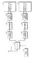
図1は、従来技術に係るCDMA通信システムとJCDMA通信システムが使用可能な携帯用端末機の受信機能ブロックとスイッチを図示した図面である。
図1に示すように、前記CDMA通信システムの送受信周波数帯域と前記JCDMA通信システムの送受信周波数帯域は互いに異なるので、送受転換器(Duplexer)105、113を含めて、受信部帯域濾波器(Band Pass Filter)109、117などのように、特定周波数だけに選択的に動作する機能ブロックは、それぞれの周波数帯域に対応して使われる。FIG. 1 is a diagram illustrating a reception function block and a switch of a portable terminal that can use a CDMA communication system and a JCDMA communication system according to the prior art.
As shown in FIG. 1, since the transmission / reception frequency band of the CDMA communication system and the transmission / reception frequency band of the JCDMA communication system are different from each other, including the
スイッチ103は、制御部101の制御によって、前記CDMA通信システムと前記JCDMA通信システムのうち、特定通信システムを選択する。前記制御部101は、使用者の選択によって前記スイッチ103を動作させて、前記特定通信システムを使うモードで前記携帯用端末機を動作させることができる。 The
CDMA送受転換器105、低雑音増幅器(LNA:Low Niose Amplifier)107、CDMA受信部帯域濾波器109、及び混合器(Mixer)111は、CDMA通信で使われ、JCDMA送受転換器113、低雑音増幅器115、JCDMA受信部帯域濾波器117、及び混合器119は、JCDMA通信で使われる。 A
前記スイッチ103によりアンテナ100と前記CDMA送受転換器105が連結された場合、すなわち、前記携帯用端末機がCDMAモードで動作する場合、前記アンテナ100から受信された信号は、前記CDMA送受転換器105、前記低雑音増幅器107、及び前記CDMA受信部帯域濾波器109を通して、前記混合器111に伝達される。 When the
前記スイッチ103により前記アンテナ100と前記JCDMA送受転換器113が連結された場合、すなわち、前記携帯用端末機がJCDMAモードで動作する場合、前記アンテナ100から受信された信号は、前記JCDMA送受転換器113、前記低雑音増幅器115、及び前記JCDMA受信部帯域濾波器117を通して、前記混合器119に伝達される。 When the
前記CDMA通信システムの機能ブロックのうち、前記CDMA送受転換器105は前記アンテナ100と連結され、前記アンテナ100を通して受信された信号から受信信号を選択する。
前記CDMA送受転換器105から出力された信号は、送信過程で減衰したり、または雑音の影響により前記雑音を含み、非常に低い信号レベルを持つため、前記低雑音増幅器107を使って、雑音を最小化した状態に増幅する。Of the functional blocks of the CDMA communication system, the
Since the signal output from the
前記低雑音増幅器107から出力された信号には、色々な帯域の周波数が含まれているので、前記CDMA受信部帯域濾波器109を使って、前記通信システムが使う周波数帯域のみを抽出する。 Since the signal output from the
前記受信部帯域濾波器109で抽出した信号は、基地局が提供した元の信号に対して位相差と時間遅延(Time Delay)が発生した信号でありうる。よって、前記位相差と時間遅延を補償するため、同一な信号が差動(Differential)出力されるよう、二つの出力端が構成されることができる。前記の従来技術による前記受信部帯域濾波器109は、一つの入力端と二つの出力端を備える。 The signal extracted by the
前記混合器111は、前記基地局からの元の信号を復元する。前記CDMA受信部帯域濾波器109から出力された信号は、前記基地局が前記元の信号を搬送周波数に含めて伝送した信号なので、前記混合器111は、前記搬送周波数を除去して前記元の信号を復元する。以後の過程は図示されていないが、前記元の信号からの同期化処理(synchronization process)と情報獲得処理(data acquisition process)が行われる。 The mixer 111 restores the original signal from the base station. Since the signal output from the CDMA
前記スィッチ103により前記アンテナ100と前記JCDMA送受転換器113が連結された場合、すなわち、前記携帯用端末機がJCDMAモードで動作する場合、それぞれの機能ブロック、すなわち、前記JCDMA送受転換器113、前記低雑音増幅器115、前記JCDMA受信部帯域濾波器117、及び前記混合器119の機能は、前記CDMA通信システムの機能ブロックと同様である。 When the
前記CDMA通信システムと前記JCDMA通信システムは、使用する周波数帯域には差があるが、前記CDMA通信システムの送信周波数帯域は前記JCDMA通信システムの受信周波数帯域に近く、前記CDMA通信システムの受信周波数帯域は、前記JCDMA通信システムの送信周波数帯域に近い。よって、図1において、前記低雑音増幅器107、115、及び前記混合器111、119の機能ブロックは、前記2種類の通信システムにより共有されることが可能である。 The CDMA communication system and the JCDMA communication system use different frequency bands, but the transmission frequency band of the CDMA communication system is close to the reception frequency band of the JCDMA communication system, and the reception frequency band of the CDMA communication system. Is close to the transmission frequency band of the JCDMA communication system. Therefore, in FIG. 1, the functional blocks of the
しかし、図1のような既存の構造には、使われる機能ブロックが重複されているので、実際の具現時に、重複されない場合と比べて、必要な実装面積が大きくなり、重複により構成が複雑になるという問題点がある。
本発明の目的は、コード分割多重接続(CDMA)通信システムと日本式コード分割多重接続(JCDMA)通信システムが選択的に使用可能な携帯用端末機で、特定機能を共有させる装置を提供することにある。 An object of the present invention is to provide an apparatus for sharing a specific function in a portable terminal capable of selectively using a code division multiple access (CDMA) communication system and a Japanese code division multiple access (JCDMA) communication system. It is in.
本発明の他の目的は、前記コード分割多重接続通信システムと日本式コード分割多重接続通信システムが選択的に使用可能な携帯用端末機で、具現時に共用可能な機能を共用させる装置を提供することにある。 Another object of the present invention is to provide a portable terminal capable of selectively using the code division multiple access communication system and the Japanese code division multiple access communication system, and sharing a function that can be shared when implemented. There is.
前記目的を達成すべく、本発明に係る形態端末機によれば、コード分割多重接続通信システムと日本式コード分割多重接続通信システムを選択的に使用可能な携帯端末機において、アンテナを介して受信した信号から前記コード分割多重接続通信システムが使用する受信信号または前記日本式コード分割多重接続通信システムが使用する受信信号のうち一つの受信信号を選択的に分離し、前記分離した信号を低雑音増幅器(LNA:Low Noise Amplifier)に出力する第1スイッチ部と、前記低雑音増幅器が出力した信号から使用中の通信システムの周波数帯域のみを分離した特定帯域の信号を混合器(Mixer)に出力する第2スイッチ部と、を含むことを特徴とする。 In order to achieve the above object, according to the mobile terminal according to the present invention, a mobile terminal capable of selectively using a code division multiple access communication system and a Japanese code division multiple access communication system receives via an antenna. One of the received signal used by the code division multiple access communication system or the received signal used by the Japanese code division multiple access communication system is selectively separated from the received signal, and the separated signal is reduced in noise. A first switch unit that outputs to an amplifier (LNA: Low Noise Amplifier) and a signal in a specific band obtained by separating only a frequency band of a communication system in use from a signal output from the low noise amplifier is output to a mixer (Mixer) And a second switch part.
また、本発明に係る携帯端末機によれば、コード分割多重接続通信システムと日本式コード分割多重接続通信システムを選択的に使用可能な携帯端末機において、前記アンテナと、前記コード分割多重接続通信システムの送受転換器または前記日本式コード分割多重接続通信システムの送受転換器のうち一つの送受転換器とを連結する第1スイッチと、前記コード分割多重接続通信システムの送受転換器または前記日本式コード分割多重接続通信システムの送受転換器のうち一つの送受転換器と、前記低雑音増幅器とを連結する第2スイッチと、を含むことを特徴とする。 Also, according to the mobile terminal of the present invention, in the mobile terminal capable of selectively using a code division multiple access communication system and a Japanese code division multiple access communication system, the antenna and the code division multiple access communication A first switch for connecting a transmission / reception converter of the system or one of the transmission / reception converters of the transmission / reception converter of the Japanese code division multiple access communication system; and the transmission / reception converter of the code division multiple access communication system or the Japanese type And a second switch that connects one of the transmitter / receiver converters of the code division multiple access communication system to the low-noise amplifier.
本発明によれば、共用可能な機能ブロックを共有することで、設計費用と特定機能の重複具現時の複雑度、実際具現時の実装面積を減らすことができる。 According to the present invention, by sharing sharable functional blocks, it is possible to reduce the design cost, the complexity when implementing specific functions overlapping, and the mounting area when actually implementing them.
以下、本発明の好ましい実施の形態を、添付図面に基づき詳細に説明する。本発明を説明するにあたって、関連した公知機能あるいは構成についての具体的な説明が本発明の要旨を逸脱すると判断された場合、その詳細な説明を省略する。
以下、本発明は、CDMA通信システムとJCDMA通信システムが使用可能な携帯用端末機装置を提供するだけでなく、共用可能な機能が重複されないようにする装置を提供する。Hereinafter, preferred embodiments of the present invention will be described in detail with reference to the accompanying drawings. In describing the present invention, if it is determined that a specific description of a related known function or configuration departs from the gist of the present invention, a detailed description thereof will be omitted.
Hereinafter, the present invention provides not only a portable terminal device that can be used by a CDMA communication system and a JCDMA communication system, but also a device that prevents duplication of sharable functions.
図2は、本発明の実施の形態に係るCDMA通信システムとJCDMA通信システムが使用可能な携帯用端末機の受信機能ブロックとスイッチを図示した図面である。
図2に示すように、前記CDMA通信システムとJCDMA通信システムが使用可能な携帯用端末機は、アンテナ200、第1スイッチ203、CDMA送受転換器205、JCDMA送受転換器219、第2スイッチ207、低雑音増幅器209、第3スイッチ211、CDMA受信部帯域濾波器213、JCDMA受信部帯域濾波器221、第4スイッチ215、第5スイッチ223、及び混合器217で構成されることができる。FIG. 2 is a diagram illustrating a reception function block and a switch of a portable terminal that can use a CDMA communication system and a JCDMA communication system according to an embodiment of the present invention.
As shown in FIG. 2, the portable terminal capable of using the CDMA communication system and the JCDMA communication system includes an
前記送受転換器205、219は、第1スイッチ203を介して前記アンテナ200に連結され、前記アンテナ200を介して受信した信号から、周波数帯域が相違する送・受信信号を分離する。また、前記送受転換器205、219は、前記二つの通信システムの送・受信周波数帯域が相違するので、各々の通信システム周波数帯域に対応する機能ブロックが使用される。そして、前記受信部帯域濾波器213、221は、所定の受信周波数帯域のみを抽出するので、前記二つの通信システムの規格に対応する機能ブロックが使用される。 The
一方、前記CDMA通信システムの送・受信周波数帯域と前記JCDMA通信システムの送・受信周波数帯域は相違するが、近似する帯域の周波数(すなわち、前記CDMA通信システムと前記JCDMA通信システムは、使用する周波数帯域の差はあるが、前記CDMA通信システムの送信周波数帯域は、前記JCDMA通信システムの受信周波数帯域に近く、前記CDMA通信システムの受信周波数帯域は、前記JCDMA通信システムの送信周波数帯域に近い)が使用されるので、前記低雑音増幅器209、前記混合器217のような機能ブロックは共有が可能である。 On the other hand, although the transmission / reception frequency band of the CDMA communication system is different from the transmission / reception frequency band of the JCDMA communication system, the frequencies of the approximate bands (that is, the CDMA communication system and the JCDMA communication system use frequencies). Although there is a band difference, the transmission frequency band of the CDMA communication system is close to the reception frequency band of the JCDMA communication system, and the reception frequency band of the CDMA communication system is close to the transmission frequency band of the JCDMA communication system) Since it is used, functional blocks such as the
前記CDMA通信システムと前記JCDMA通信システムが使用可能な携帯用端末機は、前記制御部201の指示による前記スイッチ203、207、211、215、223の動作により、前記CDMA通信システムまたはJCDMA通信システムのうち、一つの通信システムモードで動作することができる。 A portable terminal that can use the CDMA communication system and the JCDMA communication system is connected to the CDMA communication system or the JCDMA communication system according to the operation of the
前記第1スイッチ203は、前記制御部201の制御によって、前記アンテナ200を前記CDMA送受転換器205と前記JCDMA送受転換器219のうちの一つと連結する。
前記第2スイッチ207は、前記制御部201の制御によって、前記CDMA送受転換器205と前記低雑音増幅器209、または前記JCDMA送受転換器219と前記低雑音増幅器209を選択的に連結して、前記低雑音増幅器209の共有を可能とする。The
The
前記第3スイッチ211は、前記制御部201の制御によって、前記低雑音増幅器209を前記CDMA受信部帯域濾波器213と前記JCDMA受信部帯域濾波器221のうちの一つと連結する。 The third switch 211 connects the
前記CDMA受信部帯域濾波器213または前記JCDMA受信部帯域濾波器221から出力された信号は、基地局が提供した元の信号から位相差と時間遅延が発生した信号でありうる。よって、前記位相差と時間遅延を前記混合器217で補償するために、複数の出力ポートを具備して、入力された信号を濾波(filtering)して差動(Differential)出力することができる。 The signal output from the CDMA
図2では、一つの入力端と二つの出力端で構成された前記CDMA受信部帯域濾波器213と前記JCDMA受信部帯域濾波器221が使用される。したがって、前記CDMA受信部帯域濾波器213と前記JCDMA受信部帯域濾波器221各々の出力を前記混合器217に連結するスイッチは、二つの入力端を必要とする。 In FIG. 2, the CDMA receiver band-
前記第4スイッチ215の入力端Aは、前記CDMA受信部帯域濾波器213の出力端Aと連結され、前記第4スイッチ215の入力端Bは、前記JCDMA受信部帯域濾波器221の出力端Aと連結される。そして、前記第5スイッチ223の入力端Aは、前記CDMA受信部帯域濾波器213の出力端Bと連結され、前記第5スイッチ223の入力端Bは、前記JCDMA受信部帯域濾波器221の出力端Bと連結される。 The input terminal A of the fourth switch 215 is connected to the output terminal A of the CDMA
すなわち、前記第4スイッチ215と前記第5スイッチ223は、前記制御部201の制御によって、前記CDMA受信部帯域濾波器213またはJCDMA受信部帯域濾波器221のうちの一つと前記混合器217とを連結する。 That is, the fourth switch 215 and the
結果的に、前記携帯用端末機が前記CDMA通信システムモードで動作する場合、前記アンテナ200から受信された信号は、第1スイッチ203を介して前記CDMA送受転換器205に伝送され、前記CDMA送受転換器205から出力された信号は、前記第2スイッチ207を介して前記低雑音増幅器209に伝送される。前記低雑音増幅器209から出力された信号は、前記第3スイッチ211を介して前記CDMA受信部帯域濾波器213に伝送され、前記CDMA受信部帯域濾波器213から出力された信号は、前記第4スイッチ215と前記第5スイッチ223を介して、前記混合器217に伝送される。 As a result, when the portable terminal operates in the CDMA communication system mode, a signal received from the
一方、前記携帯用端末機が前記JCDMA通信システムモードで動作する場合、前記アンテナ200から受信された信号は、第1スイッチ203を介して前記JCDMA送受転換器219に伝送され、前記JCDMA送受転換器219から出力された信号は、前記第2スイッチ207を介して前記低雑音増幅器209に伝送される。前記低雑音増幅器209から出力された信号は、前記第3スイッチ211を介して前記JCDMA受信部帯域濾波器221に伝送され、前記JCDMA受信部帯域濾波器221から出力された信号は、前記第4スイッチ215と前記第5スイッチ223を介して前記混合器217に伝送される。 Meanwhile, when the portable terminal operates in the JCDMA communication system mode, a signal received from the
以上、本発明の詳細な説明では具体的な実施の形態について説明したが、本発明の範囲から逸脱しない限度内で様々な変形が可能であることは明白である。したがって、本発明の範囲は、上述の実施の形態に限定されるのではなく、添付の特許請求の範囲だけでなく本特許請求の範囲と均等なものにより定まるべきである。 As mentioned above, although specific embodiment was described in detailed description of this invention, it is clear that various deformation | transformation are possible within the limits which do not deviate from the scope of the present invention. Therefore, the scope of the present invention should not be limited to the above-described embodiments, but should be determined not only by the appended claims but also by the equivalents of the claims.
200;アンテナ
201;制御部
203;第1スイッチ
205;CDMA送受転換器
207;第2スイッチ
209;低雑音増幅器209
211;第3スイッチ
213;CDMA受信部帯域濾波器
215;第4スイッチ
217;混合器
219;JCDMA送受転換器
221;JCDMA受信部帯域濾波器
223;第5スイッチ200;
211;
Claims (19)
Translated fromJapaneseアンテナを介して受信した信号から前記コード分割多重接続通信システムが使用する受信信号または前記日本式コード分割多重接続通信システムが使用する受信信号のうち一つの受信信号を選択的に分離し、前記分離した信号を低雑音増幅器(LNA:Low Noise Amplifier)に出力する第1スイッチ部と、
前記低雑音増幅器が出力した信号から使用中の通信システムの周波数帯域のみを分離した特定帯域の信号を混合器(Mixer)に出力する第2スイッチ部と、を含むことを特徴とする携帯端末機。In a mobile terminal capable of selectively using a Code Division Multiple Access (CDMA) communication system and a Japanese Code Division Multiple Access (JCDMA) communication system,
One of the received signals used by the code division multiple access communication system or the received signal used by the Japanese code division multiple access communication system is selectively separated from a signal received via an antenna, and the separation is performed. A first switch unit that outputs the processed signal to a low noise amplifier (LNA);
And a second switch unit for outputting a signal in a specific band obtained by separating only a frequency band of a communication system in use from a signal output from the low noise amplifier to a mixer. .
前記アンテナと、前記コード分割多重接続通信システムの送受転換器または前記日本式コード分割多重接続通信システムの送受転換器のうち一つの送受転換器とを連結する第1スイッチと、
前記コード分割多重接続通信システムの送受転換器または前記日本式コード分割多重接続通信システムの送受転換器のうち一つの送受転換器と、前記低雑音増幅器とを連結する第2スイッチと、を含むことを特徴とする請求項1に記載の携帯端末機。The first switch unit includes:
A first switch that connects the antenna and one of the transmission / reception converters of the code division multiple access communication system or the transmission / reception converter of the Japanese code division multiple access communication system;
A transmission / reception converter of the code division multiple access communication system or a transmission / reception converter of the transmission / reception converter of the Japanese code division multiple access communication system, and a second switch for connecting the low noise amplifier. The mobile terminal according to claim 1.
前記低雑音増幅器と、前記コード分割多重接続通信システムの受信部帯域濾波器(Band Pass Filter)または前記日本式コード分割多重接続通信システムの受信部帯域濾波器のうち一つの濾波器とを連結する第3スイッチと、
前記コード分割多重接続通信システムの受信部帯域濾波器または前記日本式コード分割多重接続通信システムの受信部帯域濾波器のうち一つの受信部帯域濾波器と、前記混合器とを連結する第4スイッチと、を含むことを特徴とする請求項1に記載の携帯端末機。The second switch unit is
The low noise amplifier is connected to one of the receiver band filter of the code division multiple access communication system or one of the receiver band filters of the Japanese code division multiple access communication system. A third switch;
A fourth switch for connecting the mixer with the receiver band filter of the receiver band filter of the code division multiple access communication system or the receiver band filter of the Japanese code division multiple access communication system. The mobile terminal according to claim 1, further comprising:
前記第2スイッチ部は、
前記コード分割多重接続通信システムの受信部帯域濾波器または前記日本式コード分割多重接続通信システムの受信部帯域濾波器のうち一つの受信部帯域濾波器と、前記混合器とを連結する第5スイッチをさらに含むことを特徴とする請求項3に記載の携帯端末機。Two output ends of the receiver band filter of the code division multiple access communication system and the receiver band filter of the Japanese code division multiple access communication system, respectively,
The second switch unit is
A fifth switch for connecting the mixer to the receiver band filter of the receiver band filter of the code division multiple access communication system or the receiver band filter of the Japanese code division multiple access communication system. The mobile terminal according to claim 3, further comprising:
前記アンテナと、前記コード分割多重接続通信システムの送受転換器または前記日本式コード分割多重接続通信システムの送受転換器のうち一つの送受転換器とを連結する第1スイッチと、
前記コード分割多重接続通信システムの送受転換器または前記日本式コード分割多重接続通信システムの送受転換器のうち一つの送受転換器と、前記低雑音増幅器とを連結する第2スイッチと、を含むことを特徴とする携帯端末機。In a portable terminal capable of selectively using a code division multiple access communication system and a Japanese code division multiple access communication system,
A first switch that connects the antenna and one of the transmission / reception converters of the code division multiple access communication system or the transmission / reception converter of the Japanese code division multiple access communication system;
A transmission / reception converter of the code division multiple access communication system or a transmission / reception converter of the transmission / reception converter of the Japanese code division multiple access communication system, and a second switch for connecting the low noise amplifier. A portable terminal characterized by
前記低雑音増幅器と、前記コード分割多重接続通信システムの受信部帯域濾波器(Band Pass Filter)または前記日本式コード分割多重接続通信システムの受信部帯域濾波器のうち一つの濾波器とを連結する第3スイッチと、
前記コード分割多重接続通信システムの受信部帯域濾波器または前記日本式コード分割多重接続通信システムの受信部帯域濾波器のうち一つの受信部帯域濾波器と、前記混合器とを連結する第4スイッチと、をさらに含むことを特徴とする請求項11に記載の携帯端末機。The portable terminal is
The low noise amplifier is connected to one of the receiver band filter of the code division multiple access communication system or one of the receiver band filters of the Japanese code division multiple access communication system. A third switch;
A fourth switch for connecting the mixer with the receiver band filter of the receiver band filter of the code division multiple access communication system or the receiver band filter of the Japanese code division multiple access communication system. The mobile terminal according to claim 11, further comprising:
前記携帯端末機は、
前記コード分割多重接続通信システムの受信部帯域濾波器または前記日本式コード分割多重接続通信システムの受信部帯域濾波器のうち一つの受信部帯域濾波器と、前記混合器とを連結する第5スイッチをさらに含むことを特徴とする請求項12に記載の携帯端末機Two output ends of the receiver band filter of the code division multiple access communication system and the receiver band filter of the Japanese code division multiple access communication system, respectively,
The portable terminal is
A fifth switch for connecting the mixer to the receiver band filter of the receiver band filter of the code division multiple access communication system or the receiver band filter of the Japanese code division multiple access communication system. The mobile terminal according to claim 12, further comprising:
Applications Claiming Priority (1)
| Application Number | Priority Date | Filing Date | Title |
|---|---|---|---|
| KR20060038542AKR20070106091A (en) | 2006-04-28 | 2006-04-28 | Code Division Multiple Access Communication System and Japanese Code Division Multiple Access Communication System |
Publications (1)
| Publication Number | Publication Date |
|---|---|
| JP2007300645Atrue JP2007300645A (en) | 2007-11-15 |
Family
ID=38335652
Family Applications (1)
| Application Number | Title | Priority Date | Filing Date |
|---|---|---|---|
| JP2007121186APendingJP2007300645A (en) | 2006-04-28 | 2007-05-01 | Code division multiple access communication system and Japanese code division multiple access communication system sharing device |
Country Status (5)
| Country | Link |
|---|---|
| US (1) | US20070281736A1 (en) |
| EP (1) | EP1850492A3 (en) |
| JP (1) | JP2007300645A (en) |
| KR (1) | KR20070106091A (en) |
| CN (1) | CN101064580A (en) |
Families Citing this family (1)
| Publication number | Priority date | Publication date | Assignee | Title |
|---|---|---|---|---|
| CN101827050B (en)* | 2010-04-11 | 2012-11-28 | 哈尔滨工业大学(威海) | Novel CDMA downlink communication method and system |
Citations (6)
| Publication number | Priority date | Publication date | Assignee | Title |
|---|---|---|---|---|
| JPH09284168A (en)* | 1996-04-17 | 1997-10-31 | Sanyo Electric Co Ltd | Microwave integrated circuit and communication system terminal equipment using the microwave integrated circuit |
| JPH1032519A (en)* | 1996-07-16 | 1998-02-03 | Nec Corp | Radio communication equipment |
| JP2000188522A (en)* | 1998-12-22 | 2000-07-04 | Hitachi Ltd | Mobile radio terminal and surface acoustic wave antenna duplexer |
| US6097974A (en)* | 1997-12-12 | 2000-08-01 | Ericsson Inc. | Combined GPS and wide bandwidth radiotelephone terminals and methods |
| JP2002543658A (en)* | 1999-04-23 | 2002-12-17 | コネクサント システムズ インコーポレイテッド | System and process for shared function block CDMA / GSM communication transceiver |
| JP2007521762A (en)* | 2003-05-23 | 2007-08-02 | スカイワークス ソリューションズ,インコーポレイテッド | Shared function block / multimode / multiband communication transceiver |
Family Cites Families (9)
| Publication number | Priority date | Publication date | Assignee | Title |
|---|---|---|---|---|
| US6415001B1 (en)* | 1998-12-01 | 2002-07-02 | Conexant Systems, Inc. | System and process for shared frequency source multi-band transmitters and receivers |
| KR100276673B1 (en)* | 1998-12-26 | 2001-01-15 | 서평원 | Apparatus and method for data transmission / reception in WPU system |
| US6735426B1 (en)* | 2001-01-25 | 2004-05-11 | National Semiconductor Corporation | Multiple-band wireless transceiver with quadrature conversion transmitter and receiver circuits |
| KR100438425B1 (en)* | 2001-10-13 | 2004-07-03 | 삼성전자주식회사 | Mobile communication apparatus having multi-band antenna |
| JP2003347963A (en)* | 2002-05-27 | 2003-12-05 | Samsung Electro Mech Co Ltd | High frequency composite component |
| KR20040052286A (en)* | 2002-12-16 | 2004-06-23 | 삼성전기주식회사 | High frequency composite component |
| US6944427B2 (en)* | 2003-01-31 | 2005-09-13 | Motorola, Inc. | Reduced crossmodulation operation of a multimode communication device |
| US7376440B2 (en)* | 2003-04-16 | 2008-05-20 | Kyocera Wireless Corp. | N-plexer systems and methods for use in a wireless communications device |
| JP4487695B2 (en)* | 2004-09-07 | 2010-06-23 | 日本電気株式会社 | Multiband radio |
- 2006
- 2006-04-28KRKR20060038542Apatent/KR20070106091A/ennot_activeCeased
- 2007
- 2007-04-19USUS11/788,110patent/US20070281736A1/ennot_activeAbandoned
- 2007-04-27EPEP20070008630patent/EP1850492A3/ennot_activeWithdrawn
- 2007-04-28CNCNA200710100915XApatent/CN101064580A/enactivePending
- 2007-05-01JPJP2007121186Apatent/JP2007300645A/enactivePending
Patent Citations (6)
| Publication number | Priority date | Publication date | Assignee | Title |
|---|---|---|---|---|
| JPH09284168A (en)* | 1996-04-17 | 1997-10-31 | Sanyo Electric Co Ltd | Microwave integrated circuit and communication system terminal equipment using the microwave integrated circuit |
| JPH1032519A (en)* | 1996-07-16 | 1998-02-03 | Nec Corp | Radio communication equipment |
| US6097974A (en)* | 1997-12-12 | 2000-08-01 | Ericsson Inc. | Combined GPS and wide bandwidth radiotelephone terminals and methods |
| JP2000188522A (en)* | 1998-12-22 | 2000-07-04 | Hitachi Ltd | Mobile radio terminal and surface acoustic wave antenna duplexer |
| JP2002543658A (en)* | 1999-04-23 | 2002-12-17 | コネクサント システムズ インコーポレイテッド | System and process for shared function block CDMA / GSM communication transceiver |
| JP2007521762A (en)* | 2003-05-23 | 2007-08-02 | スカイワークス ソリューションズ,インコーポレイテッド | Shared function block / multimode / multiband communication transceiver |
Also Published As
| Publication number | Publication date |
|---|---|
| CN101064580A (en) | 2007-10-31 |
| EP1850492A2 (en) | 2007-10-31 |
| KR20070106091A (en) | 2007-11-01 |
| US20070281736A1 (en) | 2007-12-06 |
| EP1850492A3 (en) | 2007-12-19 |
Similar Documents
| Publication | Publication Date | Title |
|---|---|---|
| JP2586333B2 (en) | Wireless communication device | |
| CN211702017U (en) | Filter circuit and high-frequency module | |
| JPH0918397A (en) | Multiband high frequency circuit for mobile radio equipment | |
| JP2016519452A (en) | Wireless modem front-end partition implementation | |
| JP2002325049A (en) | Communication terminal that can be shared by different communication systems, antenna duplexer and power amplifier used therefor | |
| CN113037323A (en) | Radio frequency circuit, control method of radio frequency circuit and electronic equipment | |
| CN102404021A (en) | Duplex amplifying module, radio frequency front end module and multi-mode terminal | |
| EP1811678A2 (en) | Radio frequency signal transmission/reception apparatus and radio frequency signal transmission/reception method | |
| JP2009094713A (en) | Module and mobile communication terminal using the same | |
| JP4646827B2 (en) | Multiband wireless communication apparatus and filter operation control method | |
| GB2347292A (en) | Economical bandpass filter arrangement for a multi-band mobile phone receiver | |
| JP2006310968A (en) | Wireless communication device | |
| JP3816356B2 (en) | Wireless transmitter | |
| CN115664451A (en) | RF front-end circuits, equipment terminals and chips | |
| JP2002009679A (en) | Wireless terminal | |
| US7729448B2 (en) | Frontend module having two inputs for the reception of transmitted signals | |
| KR20040078699A (en) | Mobile multimode terminal with joint power amplifier | |
| JP4988630B2 (en) | Radio signal processing circuit and radio module | |
| WO2000051257A1 (en) | Radio terminal device | |
| EP1083673A1 (en) | Radio device and transmitting/receiving method | |
| JP2007300645A (en) | Code division multiple access communication system and Japanese code division multiple access communication system sharing device | |
| JPH09261104A (en) | Multi-mode mobile radio | |
| KR100384885B1 (en) | Transceiver of mobile communication terminal for dual band/tri mode | |
| KR100384882B1 (en) | Dual band transceiver of mobile communication terminal | |
| CN113872616A (en) | Communication device and communication method |
Legal Events
| Date | Code | Title | Description |
|---|---|---|---|
| A977 | Report on retrieval | Free format text:JAPANESE INTERMEDIATE CODE: A971007 Effective date:20091027 | |
| A131 | Notification of reasons for refusal | Free format text:JAPANESE INTERMEDIATE CODE: A131 Effective date:20091104 | |
| A02 | Decision of refusal | Free format text:JAPANESE INTERMEDIATE CODE: A02 Effective date:20100330 |