JP2007293042A - Music performance program and music performance apparatus - Google Patents
Music performance program and music performance apparatusDownload PDFInfo
- Publication number
- JP2007293042A JP2007293042AJP2006120926AJP2006120926AJP2007293042AJP 2007293042 AJP2007293042 AJP 2007293042AJP 2006120926 AJP2006120926 AJP 2006120926AJP 2006120926 AJP2006120926 AJP 2006120926AJP 2007293042 AJP2007293042 AJP 2007293042A
- Authority
- JP
- Japan
- Prior art keywords
- acceleration
- data
- track data
- peak value
- track
- Prior art date
- Legal status (The legal status is an assumption and is not a legal conclusion. Google has not performed a legal analysis and makes no representation as to the accuracy of the status listed.)
- Granted
Links
Images


Classifications
- G—PHYSICS
- G10—MUSICAL INSTRUMENTS; ACOUSTICS
- G10H—ELECTROPHONIC MUSICAL INSTRUMENTS; INSTRUMENTS IN WHICH THE TONES ARE GENERATED BY ELECTROMECHANICAL MEANS OR ELECTRONIC GENERATORS, OR IN WHICH THE TONES ARE SYNTHESISED FROM A DATA STORE
- G10H1/00—Details of electrophonic musical instruments
- G10H1/32—Constructional details
- G10H1/34—Switch arrangements, e.g. keyboards or mechanical switches specially adapted for electrophonic musical instruments
- G10H1/344—Structural association with individual keys
- G10H1/348—Switches actuated by parts of the body other than fingers
- A—HUMAN NECESSITIES
- A63—SPORTS; GAMES; AMUSEMENTS
- A63F—CARD, BOARD, OR ROULETTE GAMES; INDOOR GAMES USING SMALL MOVING PLAYING BODIES; VIDEO GAMES; GAMES NOT OTHERWISE PROVIDED FOR
- A63F2300/00—Features of games using an electronically generated display having two or more dimensions, e.g. on a television screen, showing representations related to the game
- A63F2300/10—Features of games using an electronically generated display having two or more dimensions, e.g. on a television screen, showing representations related to the game characterized by input arrangements for converting player-generated signals into game device control signals
- A63F2300/1006—Features of games using an electronically generated display having two or more dimensions, e.g. on a television screen, showing representations related to the game characterized by input arrangements for converting player-generated signals into game device control signals having additional degrees of freedom
- A—HUMAN NECESSITIES
- A63—SPORTS; GAMES; AMUSEMENTS
- A63F—CARD, BOARD, OR ROULETTE GAMES; INDOOR GAMES USING SMALL MOVING PLAYING BODIES; VIDEO GAMES; GAMES NOT OTHERWISE PROVIDED FOR
- A63F2300/00—Features of games using an electronically generated display having two or more dimensions, e.g. on a television screen, showing representations related to the game
- A63F2300/80—Features of games using an electronically generated display having two or more dimensions, e.g. on a television screen, showing representations related to the game specially adapted for executing a specific type of game
- A63F2300/8047—Music games
- G—PHYSICS
- G10—MUSICAL INSTRUMENTS; ACOUSTICS
- G10H—ELECTROPHONIC MUSICAL INSTRUMENTS; INSTRUMENTS IN WHICH THE TONES ARE GENERATED BY ELECTROMECHANICAL MEANS OR ELECTRONIC GENERATORS, OR IN WHICH THE TONES ARE SYNTHESISED FROM A DATA STORE
- G10H2220/00—Input/output interfacing specifically adapted for electrophonic musical tools or instruments
- G10H2220/155—User input interfaces for electrophonic musical instruments
- G10H2220/201—User input interfaces for electrophonic musical instruments for movement interpretation, i.e. capturing and recognizing a gesture or a specific kind of movement, e.g. to control a musical instrument
- G10H2220/206—Conductor baton movement detection used to adjust rhythm, tempo or expressivity of, e.g. the playback of musical pieces
- G—PHYSICS
- G10—MUSICAL INSTRUMENTS; ACOUSTICS
- G10H—ELECTROPHONIC MUSICAL INSTRUMENTS; INSTRUMENTS IN WHICH THE TONES ARE GENERATED BY ELECTROMECHANICAL MEANS OR ELECTRONIC GENERATORS, OR IN WHICH THE TONES ARE SYNTHESISED FROM A DATA STORE
- G10H2220/00—Input/output interfacing specifically adapted for electrophonic musical tools or instruments
- G10H2220/155—User input interfaces for electrophonic musical instruments
- G10H2220/395—Acceleration sensing or accelerometer use, e.g. 3D movement computation by integration of accelerometer data, angle sensing with respect to the vertical, i.e. gravity sensing
Landscapes
- Physics & Mathematics (AREA)
- Engineering & Computer Science (AREA)
- Acoustics & Sound (AREA)
- Multimedia (AREA)
- Electrophonic Musical Instruments (AREA)
- Indexing, Searching, Synchronizing, And The Amount Of Synchronization Travel Of Record Carriers (AREA)
Abstract
Translated fromJapaneseDescription
Translated fromJapanese本発明は、音楽演奏プログラムおよび音楽演奏装置に関し、より特定的には、加速度センサを備えた入力装置を振ることに応じて音楽を再生する音楽演奏プログラムおよび音楽演奏装置に関する。 The present invention relates to a music performance program and a music performance device, and more particularly to a music performance program and a music performance device that reproduce music in response to shaking an input device including an acceleration sensor.
従来、音楽の指揮を取り入れてゲームを行ったり、カラオケの興趣性を高めたりすることが知られている。例えば、加速度センサを備えた指揮棒の出力に応じて、楽譜データの音程および強度のデータを読み出すタイミングが追従するよう構成された装置が開示されている(例えば、特許文献1参照)。また、ユーザが所持またはユーザに取り付け可能な運動検出器および状態検出器に備えられた加速度センサの出力に応じて、MIDI(Musical Instrument Digital Interface)データ等の音量を変化させると共に、その再生テンポを追従させる装置が開示されている(例えば、特許文献2参照)。上記特許文献2で開示された装置では、加速度センサの出力に応じて再生テンポをどの程度追随させるのか、ユーザが指定するためのボタンを装備して、指揮に基づくテンポと本来のテンポとが大きくずれないように配慮した楽音再生装置を開示している。
しかしながら、上記特許文献1や特許文献2で開示された装置等の従来の技術では、あくまでも楽曲演奏のテンポを制御することや、せいぜい指揮の強弱で演奏音量を変化させる程度の興趣性しか提供することができない。したがって、従来の技術では、ユーザが指揮する操作自体に楽しさを感じられるような娯楽的な要素を加味することができなかった。 However, the conventional technologies such as the devices disclosed in
それ故に、本発明の目的は、入力装置の動作に応じて、多様な演奏変化を生じさせて音楽を演奏する音楽演奏プログラムおよび音楽演奏装置を提供することである。 SUMMARY OF THE INVENTION Therefore, an object of the present invention is to provide a music performance program and a music performance device that perform music by causing various performance changes according to the operation of the input device.
上記の目的を達成するために、本発明は以下の構成を採用した。なお、括弧内の参照符号やステップ番号等は、本発明の理解を助けるために後述する実施形態との対応関係を示したものであって、本発明の範囲を何ら限定するものではない。 In order to achieve the above object, the present invention employs the following configuration. Note that the reference numerals in parentheses, step numbers, and the like indicate correspondence with the embodiments described later in order to help understanding of the present invention, and do not limit the scope of the present invention.
第1の発明は、少なくとも1軸方向の加速度を検出する加速度センサ(701)を備えた入力装置(7)で検出された加速度に応じて操作される装置(3)のコンピュータ(30)で実行される音楽演奏プログラムである。音楽演奏プログラムは、加速度データ取得ステップ(S54)、加速度算出ステップ(S55、S58)、トラックデータ選択ステップ(S63、S66、S70)、および音楽演奏ステップ(S68)をコンピュータに実行させる。加速度データ取得ステップは、加速度センサから出力される加速度データ(Da)を取得する。加速度算出ステップは、取得した加速度データを用いて、加速度の大きさ(V、D)を算出する。トラックデータ選択ステップは、算出された加速度の大きさに基づいて、記憶手段(33)に記憶された複数のトラックデータ(Td、図16、図17)を含む楽曲データ(Dd)から演奏対象とするトラックデータを少なくとも1つ選択する。音楽演奏ステップは、トラックデータ選択ステップで選択されたトラックデータに基づいて、音響発生機器(2a)から発生する楽音を制御するためのデータを出力する。 The first invention is executed by the computer (30) of the device (3) operated according to the acceleration detected by the input device (7) provided with the acceleration sensor (701) for detecting acceleration in at least one axial direction. Is a music performance program. The music performance program causes the computer to execute an acceleration data acquisition step (S54), an acceleration calculation step (S55, S58), a track data selection step (S63, S66, S70), and a music performance step (S68). The acceleration data acquisition step acquires acceleration data (Da) output from the acceleration sensor. In the acceleration calculating step, the magnitude (V, D) of acceleration is calculated using the acquired acceleration data. In the track data selection step, based on the calculated magnitude of acceleration, the music data (Dd) including a plurality of track data (Td, FIG. 16, FIG. 17) stored in the storage means (33) is selected as a performance target. At least one track data to be selected is selected. The music performance step outputs data for controlling the musical sound generated from the sound generator (2a) based on the track data selected in the track data selection step.
第2の発明は、上記第1の発明において、加速度ピーク値検出ステップ(S61)を、さらにコンピュータに実行させる。加速度ピーク値検出ステップは、加速度算出ステップで算出された加速度の大きさ(V)の履歴(Db)を用いて、それら加速度の大きさのピーク値(Vp)を検出する。トラックデータ選択ステップでは、加速度ピーク値検出ステップで検出された加速度の大きさのピーク値に基づいて、演奏対象とするトラックデータが選択される(S63)。 In a second aspect based on the first aspect, the computer is further caused to execute the acceleration peak value detecting step (S61). In the acceleration peak value detection step, the acceleration magnitude (V) history (Db) calculated in the acceleration calculation step is used to detect the acceleration magnitude peak value (Vp). In the track data selection step, track data to be played is selected based on the peak value of the magnitude of acceleration detected in the acceleration peak value detection step (S63).
第3の発明は、上記第1の発明において、加速度算出ステップは、差分算出ステップ(S57、S58)を含む。差分算出ステップは、前回取得した加速度データを用いて算出した加速度(Xa0、Ya0、Za0)と今回取得した加速度データを用いて算出した加速度(Xa、Ya、Za)との差分(D)を算出する。トラックデータ選択ステップでは、差分算出ステップで算出された加速度の差分に基づいて、演奏対象とするトラックデータが選択される(S66、S70)。 In a third aspect based on the first aspect, the acceleration calculating step includes a difference calculating step (S57, S58). The difference calculating step calculates a difference (D) between the acceleration (Xa0, Ya0, Za0) calculated using the previously acquired acceleration data and the acceleration (Xa, Ya, Za) calculated using the acceleration data acquired this time. To do. In the track data selection step, track data to be played is selected based on the acceleration difference calculated in the difference calculation step (S66, S70).
第4の発明は、上記第3の発明において、加速度差分ピーク値検出ステップ(S64)を、さらにコンピュータに実行させる。加速度差分ピーク値検出ステップは、差分算出ステップで算出された加速度の差分の履歴(Dc)を用いて、それら加速度の差分のピーク値(Dp)を検出する。トラックデータ選択ステップでは、加速度差分ピーク値検出ステップで検出された加速度の差分のピーク値に基づいて、演奏対象とするトラックデータが選択される。 In a fourth aspect based on the third aspect, the computer further executes an acceleration difference peak value detecting step (S64). The acceleration difference peak value detection step detects the acceleration difference peak value (Dp) using the acceleration difference history (Dc) calculated in the difference calculation step. In the track data selection step, track data to be played is selected based on the peak value of the acceleration difference detected in the acceleration difference peak value detection step.
第5の発明は、上記第1の発明において、楽曲データは、それぞれ異なったトラックデータから成る複数のトラックデータ群(Sd)を含む。加速度算出ステップでは、今回取得した加速度データから算出した加速度の大きさ(V)、および前回取得した加速度データを用いて算出した加速度と今回取得した加速度データを用いて算出した加速度との差分(D)が算出される。音楽演奏プログラムは、加速度ピーク値検出ステップおよび加速度差分ピーク値検出ステップを、さらにコンピュータに実行させる。加速度ピーク値検出ステップは、加速度算出ステップで算出された加速度の大きさの履歴を用いて、それら加速度の大きさのピーク値を検出する。加速度差分ピーク値検出ステップは、加速度算出ステップで算出された加速度の差分の履歴を用いて、それら加速度の差分のピーク値を検出する。トラックデータ選択ステップでは、加速度差分ピーク値検出ステップで検出された加速度の差分のピーク値に基づいて演奏対象とするトラックデータ群が選択され、加速度ピーク値検出ステップで検出された加速度の大きさのピーク値に基づいて演奏対象のトラックデータ群から演奏対象のトラックデータが選択される。 In a fifth aspect based on the first aspect, the song data includes a plurality of track data groups (Sd) each consisting of different track data. In the acceleration calculation step, the magnitude (V) of the acceleration calculated from the acceleration data acquired this time and the difference between the acceleration calculated using the acceleration data acquired last time and the acceleration calculated using the acceleration data acquired this time (D ) Is calculated. The music performance program further causes the computer to execute an acceleration peak value detection step and an acceleration difference peak value detection step. In the acceleration peak value detection step, the peak value of the magnitude of acceleration is detected using the history of the magnitude of acceleration calculated in the acceleration calculation step. The acceleration difference peak value detection step detects the peak value of the acceleration difference using the acceleration difference history calculated in the acceleration calculation step. In the track data selection step, a track data group to be played is selected based on the peak value of the acceleration difference detected in the acceleration difference peak value detection step, and the magnitude of the acceleration detected in the acceleration peak value detection step is selected. Based on the peak value, performance target track data is selected from the performance target track data group.
第6の発明は、上記第1の発明において、加速度センサは、入力装置に対して互いに直交する複数軸方向(X、Y、Z軸方向)の加速度をそれぞれ検出する。加速度算出ステップでは、取得した加速度データを用いて、複数軸方向それぞれの加速度ベクトルを合成した合成ベクトルの大きさが算出される。 In a sixth aspect based on the first aspect, the acceleration sensor detects accelerations in a plurality of axial directions (X, Y, Z axis directions) orthogonal to each other with respect to the input device. In the acceleration calculation step, the size of a combined vector obtained by combining the acceleration vectors in the plurality of axial directions is calculated using the acquired acceleration data.
第7の発明は、上記第3の発明において、加速度センサは、入力装置に対して互いに直交する複数軸方向の加速度をそれぞれ検出する。差分算出ステップでは、前回取得した加速度データを用いて算出した加速度と今回取得した加速度データを用いて算出した加速度との差分を複数軸方向それぞれに算出し、それら複数軸方向それぞれの差分ベクトルを合成した差分合成ベクトルの大きさが加速度の差分として算出される。 In a seventh aspect based on the third aspect, the acceleration sensor detects accelerations in a plurality of axial directions orthogonal to the input device. In the difference calculation step, the difference between the acceleration calculated using the acceleration data acquired last time and the acceleration calculated using the acceleration data acquired this time is calculated for each of the multi-axis directions, and the difference vectors for each of the multi-axis directions are combined. The magnitude of the difference composite vector is calculated as the acceleration difference.
第8の発明は、上記第1の発明において、複数のトラックデータには、それぞれ異なった楽器が割り当てられている。表示処理ステップを、さらにコンピュータに実行させる。表示処理ステップは、トラックデータに割り当てられた楽器をそれぞれ仮想ゲーム世界に配置し、トラックデータ選択ステップで選択されたトラックデータに割り当てられた楽器のみが演奏されるアクションを表示装置(2)に表示する(図8、図9)。 In an eighth aspect based on the first aspect, different musical instruments are assigned to the plurality of track data. The display processing step is further executed by the computer. In the display processing step, the musical instrument assigned to the track data is arranged in the virtual game world, and an action in which only the musical instrument assigned to the track data selected in the track data selection step is played is displayed on the display device (2). (FIGS. 8 and 9).
第9の発明は、上記第1の発明において、複数のトラックデータには、それぞれ異なった楽器の演奏データが割り当てられている。 In a ninth aspect based on the first aspect, performance data of different instruments is assigned to the plurality of track data.
第10の発明は、上記第1の発明において、トラックデータ群に割り当てられる演奏データは、他のトラックデータ群に割り当てられる演奏データに対して、同じ楽曲で奏法、ビート数、および曲調の少なくとも1つが互いに異なる。 In a tenth aspect based on the first aspect, the performance data assigned to the track data group is at least one of the playing method, beat number, and tone of the same music with respect to the performance data assigned to the other track data group. Are different from each other.
第11の発明は、上記第1の発明において、装置は、音響発生機器から楽音を発生させる音源(34、35)を備えている。楽曲データに含まれる複数のトラックデータは、それぞれ音源の制御データで構成される。音楽演奏ステップでは、トラックデータ選択ステップで選択されたトラックデータに記述された制御データが出力されて音源が制御される。 In an eleventh aspect based on the first aspect, the apparatus includes a sound source (34, 35) for generating a musical sound from a sound generating device. Each of the plurality of track data included in the music data is composed of sound source control data. In the music performance step, the control data described in the track data selected in the track data selection step is output to control the sound source.
第12の発明は、少なくとも1軸方向の加速度を検出する加速度センサを備えた入力装置で検出された加速度に応じて操作される音楽演奏装置である。音楽演奏装置は、加速度データ取得手段、加速度算出手段、トラックデータ選択手段、および音楽演奏手段を備える。加速度データ取得手段は、加速度センサから出力される加速度データを取得する。加速度算出手段は、取得した加速度データを用いて、加速度の大きさを算出する。トラックデータ選択手段は、算出された加速度の大きさに基づいて、記憶手段に記憶された複数のトラックデータを含む楽曲データから演奏対象とするトラックデータを少なくとも1つ選択する。音楽演奏手段は、トラックデータ選択手段が選択したトラックデータに基づいて、音響発生機器から発生する楽音を制御するためのデータを出力する。 A twelfth aspect of the invention is a music performance device that is operated in accordance with acceleration detected by an input device that includes an acceleration sensor that detects acceleration in at least one axial direction. The music performance device includes acceleration data acquisition means, acceleration calculation means, track data selection means, and music performance means. The acceleration data acquisition means acquires acceleration data output from the acceleration sensor. The acceleration calculation means calculates the magnitude of acceleration using the acquired acceleration data. The track data selection means selects at least one track data to be played from music data including a plurality of track data stored in the storage means based on the calculated magnitude of acceleration. The music performance means outputs data for controlling the musical sound generated from the sound generating device based on the track data selected by the track data selection means.
上記第1の発明によれば、加速度センサの加速度の大きさによって、演奏対象とするトラックを変化させるので、入力装置の振り動かし方に応じて多様な演奏変化を生じさせることができる。 According to the first aspect, since the track to be played is changed according to the magnitude of the acceleration of the acceleration sensor, various performance changes can be caused depending on how the input device is swung.
上記第2の発明によれば、加速度の大きさのピーク値によって、演奏対象とするトラックを変化させるので、入力装置の振り動かす大きさや速度に応じて音楽演奏を変化させることができる。 According to the second aspect, since the track to be played is changed according to the peak value of the magnitude of acceleration, the music performance can be changed according to the magnitude and speed of the swinging of the input device.
上記第3の発明によれば、加速度の大きさの差分によって、演奏対象とするトラックを変化させるので、入力装置の振り動かすときの柔らかさ等に応じて音楽演奏を変化させることができる。 According to the third aspect, since the track to be played is changed according to the difference in the magnitude of acceleration, the music performance can be changed according to the softness when the input device is swung.
上記第4の発明によれば、加速度の大きさの差分のピーク値によって、演奏対象とするトラックを変化させるので、入力装置の振り動かすときの拍タイミングにおけるメリハリの有無等に応じて音楽演奏を変化させることができる。 According to the fourth aspect of the invention, since the performance target track is changed according to the peak value of the difference in acceleration magnitude, the music performance is performed according to the presence / absence of sharpness in the beat timing when the input device is swung. Can be changed.
上記第5の発明によれば、加速度の大きさの差分のピーク値によって演奏対象とするトラック群を変化させ、加速度の大きさのピーク値によって当該トラック群からトラックを変化させるので、さらに多様な演奏変化を生じさせることができる。 According to the fifth aspect, the track group to be played is changed by the peak value of the difference in acceleration magnitude, and the track is changed from the track group by the peak value of acceleration magnitude. A performance change can be caused.
上記第6および第7の発明によれば、互いに直交する複数軸方向の加速度をそれぞれ検出する加速度センサを用いているため、ユーザが入力装置を持つ方向に関わらず、入力装置の振り動かし方に応じて音楽演奏を変化させることができる。 According to the sixth and seventh inventions described above, since the acceleration sensor that detects accelerations in a plurality of directions orthogonal to each other is used, the user can swing the input device regardless of the direction in which the user holds the input device. The music performance can be changed accordingly.
上記第8の発明によれば、演奏対象とする楽器が変化している様子を表示装置に表示することができる。 According to the eighth aspect, it is possible to display on the display device how the musical instrument to be played has changed.
上記第9の発明によれば、選択するトラックデータを変化させることによって演奏される楽器種が変化するため、入力装置の振り動かし方に応じて楽曲の演奏内容を変化させることができる。 According to the ninth aspect, since the musical instrument type to be played is changed by changing the track data to be selected, the performance content of the music can be changed according to how the input device is swung.
上記第10の発明によれば、選択するトラックデータ群を変化させることによって演奏される奏法、ビート数、曲調等が変化するため、入力装置の振り動かし方に応じて演奏される楽曲の表現を変えることができる。 According to the tenth aspect of the invention, since the performance method, the number of beats, the tune, etc. that are played by changing the track data group to be selected change, the expression of the music that is played according to how the input device is swung can be expressed. Can be changed.
上記第11の発明によれば、MIDIデータを用いて容易に実現することができる。 According to the eleventh aspect, it can be easily realized using MIDI data.
本発明の音楽演奏装置によれば、上述した音楽演奏プログラムと同様の効果を得ることができる。 According to the music performance device of the present invention, the same effects as those of the music performance program described above can be obtained.
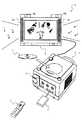
図1を参照して、本発明の一実施形態に係る音楽演奏装置について説明する。以下、説明を具体的にするために、当該音楽演奏装置を用いたゲームシステム1を一例として説明する。なお、図1は、当該ゲームシステム1を説明するための外観図である。以下、本発明の音楽演奏装置に相当する据置型ゲーム装置を一例にして、当該ゲームシステム1について説明する。 With reference to FIG. 1, a music performance device according to an embodiment of the present invention will be described. Hereinafter, for the sake of specific explanation, a
図1において、当該ゲームシステム1は、家庭用テレビジョン受像機等のスピーカ2aを備えたディスプレイ(以下、モニタと記載する)2に、接続コードを介して接続される据置型ゲーム装置(以下、単にゲーム装置と記載する)3および当該ゲーム装置3に操作情報を与えるコントローラ7によって構成される。ゲーム装置3は、接続端子を介して受信ユニット6が接続される。受信ユニット6は、コントローラ7から無線送信される送信データを受信し、コントローラ7とゲーム装置3とは無線通信によって接続される。また、ゲーム装置3には、当該ゲーム装置3に対して交換可能に用いられる情報記憶媒体の一例の光ディスク4が脱着される。ゲーム装置3の上部主面には、当該ゲーム装置3の電源ON/OFFスイッチ、ゲーム処理のリセットスイッチ、およびゲーム装置3上部の蓋を開くOPENスイッチが設けられている。ここで、プレイヤがOPENスイッチを押下することによって上記蓋が開き、光ディスク4の脱着が可能となる。 In FIG. 1, the
また、ゲーム装置3には、セーブデータ等を固定的に記憶するバックアップメモリ等を搭載する外部メモリカード5が必要に応じて着脱自在に装着される。ゲーム装置3は、光ディスク4に記憶されたゲームプログラムなどを実行することによって、その結果をゲーム画像としてモニタ2に表示する。さらに、ゲーム装置3は、外部メモリカード5に記憶されたセーブデータを用いて、過去に実行されたゲーム状態を再現して、ゲーム画像をモニタ2に表示することもできる。そして、ゲーム装置3のプレイヤは、モニタ2に表示されたゲーム画像を見ながら、コントローラ7を操作することによって、ゲーム進行を楽しむことができる。 Further, an
コントローラ7は、その内部に備える通信部75(後述)から受信ユニット6が接続されたゲーム装置3へ、例えばBluetooth(ブルートゥース;登録商標)の技術を用いて送信データを無線送信する。コントローラ7は、主にモニタ2に表示されるゲーム空間に登場するプレイヤオブジェクトを操作するための操作手段である。コントローラ7は、複数の操作ボタン、キー、およびスティック等の操作部が設けられている。また、後述により明らかとなるが、コントローラ7は、当該コントローラ7から見た画像を撮像する撮像情報演算部74を備えている。また、撮像情報演算部74の撮像対象の一例として、モニタ2の表示画面近傍に2つのLEDモジュール(以下、マーカと記載する)8Lおよび8Rが設置される。これらマーカ8Lおよび8Rは、それぞれモニタ2の前方に向かって赤外光を出力する。なお、本実施例では、撮像情報演算部74による撮像情報を用いないため、マーカ8Lおよび8Rを設置しなくてもかまわない。 The
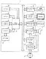
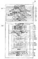
次に、図2を参照して、ゲーム装置3の構成について説明する。なお、図2は、ゲーム装置3の機能ブロック図である。 Next, the configuration of the
図2において、ゲーム装置3は、各種プログラムを実行する例えばリスク(RISC)CPU(セントラルプロセッシングユニット)30を備える。CPU30は、図示しないブートROMに記憶された起動プログラムを実行し、メインメモリ33等のメモリの初期化等を行った後、光ディスク4に記憶されているゲームプログラムの実行し、そのゲームプログラムに応じたゲーム処理等を行うものである。なお、光ディスク4に記憶されているゲームプログラムが本発明の音楽演奏プログラムを含んでおり、CPU30は、上記ゲーム処理の中でコントローラ7の動きに応じて演奏するための音楽演奏処理も行っている。CPU30には、メモリコントローラ31を介して、GPU(Graphics Processing Unit)32、メインメモリ33、DSP(Digital Signal Processor)34、およびARAM(Audio RAM)35が接続される。また、メモリコントローラ31には、所定のバスを介して、コントローラI/F(インターフェース)36、ビデオI/F37、外部メモリI/F38、オーディオI/F39、およびディスクI/F41が接続され、それぞれ受信ユニット6、モニタ2、外部メモリカード5、スピーカ2a、およびディスクドライブ40が接続されている。 In FIG. 2, the
GPU32は、CPU30の命令に基づいて画像処理を行うものあり、例えば、3Dグラフィックスの表示に必要な計算処理を行う半導体チップで構成される。GPU32は、図示しない画像処理専用のメモリやメインメモリ33の一部の記憶領域を用いて画像処理を行う。GPU32は、これらを用いてモニタ2に表示すべきゲーム画像データやムービ映像を生成し、適宜メモリコントローラ31およびビデオI/F37を介してモニタ2に出力する。 The
メインメモリ33は、CPU30で使用される記憶領域であって、CPU30の処理に必要なゲームプログラム等を適宜記憶する。例えば、メインメモリ33は、CPU30によって光ディスク4から読み出されたゲームプログラムや各種データ等を記憶する。このメインメモリ33に記憶されたゲームプログラムや各種データ等がCPU30によって実行される。 The
DSP34は、ゲームプログラム実行時にCPU30において処理されるサウンドデータ(例えば、MIDI(Musical Instrument Digital Interface)データ)等を処理するものであり、そのサウンドデータ等を記憶するためのARAM35が接続される。そして、MIDIデータに基づいて音楽を演奏する場合、DSP34およびARAM35がMIDI音源として機能する。ARAM35は、DSP34が所定の処理(例えば、先読みしておいたゲームプログラムやサウンドデータの記憶)を行う際に用いられる。DSP34は、ARAM35に記憶されたサウンドデータを読み出し、メモリコントローラ31およびオーディオI/F39を介してモニタ2に備えるスピーカ2aに出力させる。 The
メモリコントローラ31は、データ転送を統括的に制御するものであり、上述した各種I/Fが接続される。コントローラI/F36は、例えば4つのコントローラI/F36a〜36dで構成され、それらが有するコネクタを介して嵌合可能な外部機器とゲーム装置3とを通信可能に接続する。例えば、受信ユニット6は、上記コネクタと嵌合し、コントローラI/F36を介してゲーム装置3と接続される。上述したように受信ユニット6は、コントローラ7からの送信データを受信し、コントローラI/F36を介して当該送信データをCPU30へ出力する。ビデオI/F37には、モニタ2が接続される。外部メモリI/F38には、外部メモリカード5が接続され、その外部メモリカード5に設けられたバックアップメモリ等とアクセス可能となる。オーディオI/F39にはモニタ2に内蔵されるスピーカ2aが接続され、DSP34がARAM35から読み出したサウンドデータやディスクドライブ40から直接出力されるサウンドデータをスピーカ2aから出力可能に接続される。ディスクI/F41には、ディスクドライブ40が接続される。ディスクドライブ40は、所定の読み出し位置に配置された光ディスク4に記憶されたデータを読み出し、ゲーム装置3のバスやオーディオI/F39に出力する。 The
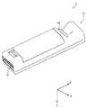
図3および図4を参照して、本発明の入力装置の一例であるコントローラ7について説明する。なお、図3は、コントローラ7の上面後方から見た斜視図である。図4は、コントローラ7を下面後方から見た斜視図である。 With reference to FIG. 3 and FIG. 4, the
図3および図4において、コントローラ7は、例えばプラスチック成型によって形成されたハウジング71を有しており、当該ハウジング71に複数の操作部72が設けられている。ハウジング71は、その前後方向を長手方向とした略直方体形状を有しており、全体として大人や子供の片手で把持可能な大きさである。 3 and 4, the
ハウジング71上面の中央前面側に、十字キー72aが設けられる。この十字キー72aは、十字型の4方向プッシュスイッチであり、矢印で示す4つの方向(前後左右)に対応する操作部分が十字の突出片にそれぞれ90°間隔で配置される。プレイヤが十字キー72aのいずれかの操作部分を押下することによって前後左右いずれかの方向を選択される。例えばプレイヤが十字キー72aを操作することによって、仮想ゲーム世界に登場するプレイヤキャラクタ等の移動方向を指示したり、カーソルの移動方向を指示したりすることができる。 A cross key 72 a is provided on the center front side of the upper surface of the
なお、十字キー72aは、上述したプレイヤの方向入力操作に応じて操作信号を出力する操作部であるが、他の態様の操作部でもかまわない。例えば、リング状に4方向の操作部分を備えたプッシュスイッチとその中央に設けられたセンタスイッチとを複合した複合スイッチを上記十字キー72aの代わりに設けてもかまわない。また、ハウジング71上面から突出した傾倒可能なスティックを倒すことによって、傾倒方向に応じて操作信号を出力する操作部を上記十字キー72aの代わりに設けてもかまわない。さらに、水平移動可能な円盤状部材をスライドさせることによって、当該スライド方向に応じた操作信号を出力する操作部を、上記十字キー72aの代わりに設けてもかまわない。また、タッチパッドを、上記十字キー72aの代わりに設けてもかまわない。また、少なくとも4つの方向(前後左右)をそれぞれ示すスイッチに対して、プレイヤによって押下されたスイッチに応じて操作信号を出力する操作部を上記十字キー72aの代わりに設けてもかまわない。 Note that the cross key 72a is an operation unit that outputs an operation signal in response to the above-described direction input operation of the player, but may be an operation unit of another mode. For example, instead of the cross key 72a, a composite switch in which a push switch having a four-direction operation portion in a ring shape and a center switch provided at the center thereof may be provided. Further, an operation unit that outputs an operation signal according to the tilt direction by tilting a tiltable stick protruding from the upper surface of the
ハウジング71上面の十字キー72aより後面側に、複数の操作ボタン72b〜72gが設けられる。操作ボタン72b〜72gは、プレイヤがボタン頭部を押下することによって、それぞれの操作ボタン72b〜72gに割り当てられた操作信号を出力する操作部である。例えば、操作ボタン72b〜72dには、Xボタン、Yボタン、およびAボタン等としての機能が割り当てられる。また、操作ボタン72e〜72gには、セレクトスイッチ、メニュースイッチ、およびスタートスイッチ等としての機能が割り当てられる。これら操作ボタン72b〜72gは、ゲーム装置3が実行するゲームプログラムに応じてそれぞれの機能が割り当てられるが、本発明の説明とは直接関連しないため詳細な説明を省略する。なお、図3に示した配置例では、操作ボタン72b〜72dは、ハウジング71上面の中央前後方向に沿って並設されている。また、操作ボタン72e〜72gは、ハウジング71上面の左右方向に沿って操作ボタン72bおよび72dの間に並設されている。そして、操作ボタン72fは、その上面がハウジング71の上面に埋没しており、プレイヤが不意に誤って押下することのないタイプのボタンである。 A plurality of
また、ハウジング71上面の十字キー72aより前面側に、操作ボタン72hが設けられる。操作ボタン72hは、遠隔からゲーム装置3本体の電源をオン/オフする電源スイッチである。この操作ボタン72hも、その上面がハウジング71の上面に埋没しており、プレイヤが不意に誤って押下することのないタイプのボタンである。 An
また、ハウジング71上面の操作ボタン72cより後面側に、複数のLED702が設けられる。ここで、コントローラ7は、他のコントローラ7と区別するためにコントローラ種別(番号)が設けられている。例えば、LED702は、コントローラ7に現在設定されている上記コントローラ種別をプレイヤに通知するために用いられる。具体的には、コントローラ7から受信ユニット6へ送信データを送信する際、上記コントローラ種別に応じて複数のLED702のうち、種別に対応するLEDが点灯する。 A plurality of
一方、ハウジング71下面には、凹部が形成されている。ハウジング71下面の凹部は、プレイヤがコントローラ7を把持したときに当該プレイヤの人差し指や中指が位置するような位置に形成される。そして、上記凹部の後面側傾斜面には、操作ボタン72iが設けられる。操作ボタン72iは、例えばBボタンとして機能する操作部であり、シューティングゲームにおけるトリガスイッチや、プレイヤオブジェクトを所定オブジェクトに対して注目させる操作等に用いられる。 On the other hand, a recess is formed on the lower surface of the
また、ハウジング71前面には、撮像情報演算部74の一部を構成する撮像素子743が設けられる。ここで、撮像情報演算部74は、コントローラ7が撮像した画像データを解析してその中で輝度が高い場所を判別してその場所の重心位置やサイズなどを検出するためのシステムであり、例えば、最大200フレーム/秒程度のサンプリング周期であるため比較的高速なコントローラ7の動きでも追跡して解析することができる。また、ハウジング70の後面には、コネクタ73が設けられている。コネクタ73は、例えば32ピンのエッジコネクタであり、例えば接続ケーブルと嵌合して接続するために利用される。なお、本発明では、この撮像情報演算部74からの情報を用いないため、ここではこれ以上の説明を省略する。 An
ここで、説明を具体的にするために、コントローラ7に対して設定する座標系について定義する。図3および図4に示すように、互いに直交するXYZ軸をコントローラ7に対して定義する。具体的には、コントローラ7の前後方向となるハウジング71の長手方向をZ軸とし、コントローラ7の前面(撮像情報演算部74が設けられている面)方向をZ軸正方向とする。また、コントローラ7の上下方向をY軸とし、ハウジング71の上面(十字キー72aが設けられた面)方向をY軸正方向とする。さらに、コントローラ7の左右方向をX軸とし、ハウジング71の左側面(図3では表されずに図4で表されている側面)方向をX軸正方向とする。 Here, in order to explain specifically, a coordinate system set for the
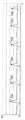
次に、図5Aおよび図5Bを参照して、コントローラ7の内部構造について説明する。なお、図5Aは、コントローラ7の上筐体(ハウジング71の一部)を外した状態を示す斜視図である。図5Bは、コントローラ7の下筐体(ハウジング71の一部)を外した状態を示す斜視図である。ここで、図5Bに示す基板700は、図5Aに示す基板700の裏面から見た斜視図となっている。 Next, the internal structure of the
図5Aにおいて、ハウジング71の内部には基板700が固設されており、当該基板700の上主面上に操作ボタン72a〜72h、加速度センサ701、LED702、水晶振動子703、無線モジュール753、およびアンテナ754等が設けられる。そして、これらは、基板700等に形成された配線(図示せず)によってマイコン751(図6参照)に接続される。加速度センサ701は、コントローラ7が配置された3次元空間における傾きや振動等の算出に用いることができる加速度を検出して出力する。 5A, a
より詳細には、図6に示すように、コントローラ7は3軸の加速度センサ701を備えていることが好ましい。この3軸の加速度センサ701は、3方向、すなわち、上下方向(図3に示すY軸)、左右方向(図3に示すX軸)、および前後方向(図3に示すZ軸)で直線加速度を検知する。また、他の実施形態においては、ゲーム処理に用いる制御信号の種類によっては、X軸とY軸(または他の対になった軸)とのそれぞれに沿った直線加速度のみを検知する2軸の加速度検出手段を使用してもよい。さらに、他の実施形態においては、ゲーム処理に用いる制御信号の種類によっては、XYZ軸のいずれか1軸に沿った直線加速度のみを検知する1軸の加速度検出手段を使用してもよい。例えば、この3軸、2軸、または1軸の加速度センサ701は、アナログ・デバイセズ株式会社(Analog Devices, Inc.)またはSTマイクロエレクトロニクス社(STMicroelectronics N.V.)から入手可能であるタイプのものでもよい。加速度センサ701は、シリコン微細加工されたMEMS(Micro Electro Mechanical Systems:微小電子機械システム)の技術に基づいた静電容量式(静電容量結合式)であることが好ましい。しかしながら、既存の加速度検出手段の技術(例えば、圧電方式や圧電抵抗方式)あるいは将来開発される他の適切な技術を用いて3軸、2軸、または1軸の加速度センサ701が提供されてもよい。 More specifically, as shown in FIG. 6, the
加速度センサ701に用いられるような加速度検出手段は、加速度センサ701の持つ各軸に対応する直線に沿った加速度(直線加速度)のみを検知することができる。つまり、加速度センサ701からの直接の出力は、その1軸、2軸、または3軸のそれぞれに沿った直線加速度(静的または動的)を示す信号である。このため、加速度センサ701は、非直線状(例えば、円弧状)の経路に沿った動き、回転、回転運動、角変位、傾斜、位置、または姿勢等の物理特性を直接検知することはできない。 The acceleration detecting means used in the
しかしながら、加速度センサ701から出力される加速度の信号に対して追加の処理を行うことによって、コントローラ7に関するさらなる情報を推測または算出(判定)することができることは、当業者であれば本明細書の説明から容易に理解できるであろう。例えば、静的な加速度(重力加速度)が検知されると、加速度センサ701からの出力を用いて、傾斜角度と検知された加速度とを用いた演算によって重力ベクトルに対する対象(コントローラ7)の傾きを判定することができる。このように、加速度センサ701をマイコン751(またはゲーム装置3に含まれるCPU30等の他のプロセッサ)と組み合わせて用いることによって、コントローラ7の傾き、姿勢、または位置を判定することができる。同様に、加速度センサ701を備えるコントローラ7がプレイヤの手で動的に加速されて動かされる場合に、加速度センサ701によって生成される加速度信号を処理することによって、コントローラ7の様々な動きおよび/または位置を算出することができる。他の実施例では、加速度センサ701は、信号をマイコン751に出力する前に内蔵の加速度検出手段から出力される加速度信号に対して所望の処理を行うための、組込み式の信号処理装置または他の種類の専用の処理装置を備えていてもよい。 However, it is understood by those skilled in the art that additional information regarding the
また、無線モジュール753およびアンテナ754を有する通信部75によって、コントローラ7がワイヤレスコントローラとして機能する。なお、水晶振動子703は、後述するマイコン751の基本クロックを生成する。 Further, the
一方、図5Bにおいて、基板700の下主面上の前端縁に撮像情報演算部74が設けられる。撮像情報演算部74は、コントローラ7の前方から順に赤外線フィルタ741、レンズ742、撮像素子743、および画像処理回路744によって構成されており、それぞれ基板700の下主面に取り付けられる。また、基板700の下主面上の後端縁にコネクタ73が取り付けられる。そして、操作ボタン72iが撮像情報演算部74の後方の基板700の下主面上に取り付けられていて、それよりさらに後方に、電池705が収容される。電池705とコネクタ73との間の基板700の下主面上には、バイブレータ704が取り付けられる。このバイブレータ704は、例えば振動モータやソレノイドであってよい。バイブレータ704が作動することによってコントローラ7に振動が発生するので、それを把持しているプレイヤの手にその振動が伝達され、いわゆる振動対応ゲームが実現できる。 On the other hand, in FIG. 5B, an imaging
次に、図6を参照して、コントローラ7の内部構成について説明する。なお、図6は、コントローラ7の構成を示すブロック図である。 Next, the internal configuration of the
撮像情報演算部74は、赤外線フィルタ741、レンズ742、撮像素子743、および画像処理回路744を含んでいる。赤外線フィルタ741は、コントローラ7の前方から入射する光から赤外線のみを通過させる。レンズ742は、赤外線フィルタ741を透過した赤外線を集光して撮像素子743へ出射する。撮像素子743は、例えばCMOSセンサやあるいはCCDのような固体撮像素子であり、レンズ742が集光した赤外線を撮像する。したがって、撮像素子743は、赤外線フィルタ741を通過した赤外線だけを撮像して画像データを生成する。撮像素子743で生成された画像データは、画像処理回路744で処理される。具体的には、画像処理回路744は、撮像素子743から得られた画像データを処理して高輝度部分を検知し、それらの位置座標や面積を検出した結果を示す処理結果データを通信部75へ出力する。なお、これらの撮像情報演算部74は、コントローラ7のハウジング71に固設されており、ハウジング71自体の方向を変えることによってその撮像方向を変更することができる。 The imaging
加速度センサ701は、上述したようにコントローラ7の上下方向(Y軸方向)、左右方向(X軸方向)、および前後方向(Z軸方向)の3軸成分に分けてそれぞれ加速度を検知して出力するセンサである。加速度センサ701が検知した3軸成分の加速度を示すデータは、それぞれ通信部75へ出力される。この加速度センサ701から出力される加速度データに基づいて、コントローラ7の傾きや動きを判別することができる。なお、加速度センサ701は、特定のアプリケーションで必要なデータに応じて何れか2軸に対してそれぞれ加速度を検出する加速度センサや何れか1軸(例えば、Y軸)に対して加速度を検出する加速度センサが用いられてもかまわない。 As described above, the
通信部75は、マイクロコンピュータ(Micro Computer:マイコン)751、メモリ752、無線モジュール753、およびアンテナ754を含んでいる。マイコン751は、処理の際にメモリ752を記憶領域として用いながら、送信データを無線送信する無線モジュール753を制御する。 The
コントローラ7に設けられた操作部72からの操作信号(キーデータ)、加速度センサ701からの3軸方向の加速度信号(X、Y、およびZ軸方向加速度データ)、および撮像情報演算部74からの処理結果データは、マイコン751に出力される。マイコン751は、入力した各データ(キーデータ、X、Y、およびZ軸方向加速度データ、処理結果データ)を受信ユニット6へ送信する送信データとして一時的にメモリ752に格納する。ここで、通信部75から受信ユニット6への無線送信は、所定の周期毎に行われるが、ゲームの処理は1/60秒を単位として行われることが一般的であるので、それよりも短い周期で送信を行うことが必要となる。具体的には、ゲームの処理単位は16.7ms(1/60秒)であり、ブルートゥース(登録商標)で構成される通信部75の送信間隔は5msである。マイコン751は、受信ユニット6への送信タイミングが到来すると、メモリ752に格納されている送信データを一連の操作情報として出力し、無線モジュール753へ出力する。そして、無線モジュール753は、例えばBluetooth(ブルートゥース;登録商標)の技術を用いて、所定周波数の搬送波を用いて操作情報をその電波信号としてアンテナ754から放射する。つまり、コントローラ7に設けられた操作部72からのキーデータ、加速度センサ701からのX、Y、およびZ軸方向加速度データ、および撮像情報演算部74からの処理結果データがコントローラ7から送信される。そして、ゲーム装置3の受信ユニット6でその電波信号を受信し、ゲーム装置3で当該電波信号を復調や復号することによって、一連の操作情報(キーデータ、X、Y、およびZ軸方向加速度データ、および処理結果データ)を取得する。そして、ゲーム装置3のCPU30は、取得した操作情報とゲームプログラムとに基づいて、ゲーム処理を行う。なお、Bluetooth(登録商標)の技術を用いて通信部75を構成する場合、通信部75は、他のデバイスから無線送信された送信データを受信する機能も備えることができる。 An operation signal (key data) from the
次に、ゲーム装置3が行う具体的な処理を説明する前に、本ゲーム装置3で行うゲームの概要について説明する。図7に示すように、コントローラ7は、全体として大人や子供の片手で把持可能な大きさである。そして、ゲームシステム1でコントローラ7を用いてゲームをプレイするためには、コントローラ7を指揮棒のように振り動かして、再生される音楽の変化を楽しむことができる。具体的には、プレイヤは、モニタ2で表現されている楽器群(または、楽器群をそれぞれ演奏するキャラクタ)を表すゲーム画像を見ながら、演奏する楽器数や種類(音の数)、奏法(レガートやスタッカート)、ビート数(8ビートや16ビート)、音調(長調や短調)、演奏テンポ、演奏音量等がプレイヤの望む演奏となるようにコントローラ7を指揮棒のように振り動かす。これによって、コントローラ7からプレイヤがコントローラ7を振り動かしたことによる操作情報(具体的には、X、Y、およびZ軸方向加速度データ)がゲーム装置3に与えられる。 Next, before describing specific processing performed by the
例えば、図8および図9に示すように、モニタ2にはプレイヤキャラクタPCと、当該プレイヤキャラクタPCが指揮する楽器群(または、楽器それぞれを演奏するキャラクタ群)とが表示される。なお、図8および図9の例では、ピアノP、サキソフォンSAX、クラリネットCL、ギターG、ホルンHRN、およびバイオリンVNが表示される楽器群の一例として示されている。後述により明らかとなるが、プレイヤは、例えばコントローラ7を振り動かす強弱に応じて演奏する楽器数や種類(音の数)を変化させることができ、モニタ2に表示されるゲーム画像も演奏している楽器種がわかるように表現される。図8に示したゲーム画像例では、プレイヤがコントローラ7を振り動かす動作に応じて、ピアノPおよびギターGが演奏している形態を示している。また、図9に示したゲーム画像例では、プレイヤがコントローラ7を振り動かす動作に応じて、全ての楽器が演奏している形態を示している。 For example, as shown in FIGS. 8 and 9, the
図10A〜図10Cは、コントローラ7を上下方向に振り上げまたは振り下げた状態とコントローラ7に加わる加速度との関係を説明するための図である。コントローラ7にはプレイヤが振り動かすことによって生じる動的な加速度(振り加速度)と静的な重力加速度とが加わっており、加速度センサ701は、これらの加速度によって生じる上下方向(Y軸)、左右方向(X軸)、および前後方向(Z軸)の直線加速度をそれぞれ検知する。 10A to 10C are diagrams for explaining the relationship between the state in which the
図10Aに示すように、プレイヤがコントローラ7の上面(十字キー72aが設けられた面)を上に向けて水平に静止させたとき、重力加速度がY軸負方向に作用する。 As shown in FIG. 10A, when the player rests horizontally with the upper surface of the controller 7 (the surface on which the cross key 72a is provided) facing upward, the gravitational acceleration acts in the negative Y-axis direction.
一方、図10Bに示すように、プレイヤがコントローラ7を上方向へ振り上げたとき、Y軸正方向の振り加速度が生じる。そして、コントローラ7を振り上げる速度が速い程、その振り加速度が大きくなる。なお、重力加速度は、コントローラ7のY軸負方向とZ軸負方向との間の方向に作用する。 On the other hand, as shown in FIG. 10B, when the player swings the
また、図10Cに示すように、プレイヤがコントローラ7を下方向へ振り下げたとき、Y軸負方向の振り加速度が生じる。そして、コントローラ7を振り下げる速度が速い程、その振り加速度が大きくなる。なお、重力加速度は、コントローラ7のY軸負方向とZ軸正方向との間の方向に作用する。 Also, as shown in FIG. 10C, when the player swings down the
このように、プレイヤがコントローラ7を振り動かしたとき、加速度センサ701は、その振り動かす方向にその速さに応じた大きさの動的な加速度を検出する。しかしながら、現実にコントローラ7に作用する加速度は図10A〜図10Cに示すような単純な方向や大きさで生じない。実際には、振り上げまたは振り下げによる遠心力等もコントローラ7に作用し、プレイヤが左右方向にコントローラ7を振ったりひねられたりすることによって加速度が生じる方向も様々に変化する。本実施形態では、加速度センサ701が検出した3軸方向の直線加速度から算出される合成ベクトルの大きさおよび3軸方向それぞれの直線加速度の差分(つまり、加速度の変化)から算出される差分合成ベクトルの大きさを用いて、プレイヤがコントローラ7を振り動かす動作を分析している。 Thus, when the player swings the
図11Aは、プレイヤがコントローラ7を大きく振り動かし、各拍子をとるタイミングでメリハリのある振り方をしたときに現れる合成ベクトルの大きさ変化の一例を示すグラフである。図11Bは、図11Aで示す合成ベクトルを得たときに3軸方向それぞれの直線加速度の差分から算出される差分合成ベクトルの大きさ変化の一例を示すグラフである。図11Cは、図11Aで示す合成ベクトルにおいて、Y軸正方向の直線加速度が得られた期間を大きさ0として当該合成ベクトルの大きさ変化の一例を示すグラフである。なお、図11A〜図11Cは、全て横軸が同じ時間軸である。 FIG. 11A is a graph showing an example of a change in the magnitude of the combined vector that appears when the player swings the
加速度センサ701から出力される加速度データが示すX軸方向の加速度をXa、Y軸方向の加速度をYa、Z軸方向の加速度をZaとすると、合成ベクトルの大きさVは、
しかしながら、プレイヤの振り方によっては、各拍子のタイミング以外で合成ベクトルの大きさVがピークを示すこともある。例えば、上下方向へコントローラ7を振り動かすときの振り下げ時に拍子をとる場合、振り上げから振り下げに移るときに合成ベクトルの大きさVが大きくなることもある。また、一般的な指揮棒の4拍子でプレイヤがコントローラ7を振るとき、1拍子目から2拍子目移る途中で合成ベクトルの大きさVが大きくなることもある。このような拍子のタイミング以外で生じる合成ベクトルの大きさVのピークを除去するため、所定軸方向(例えば、Y軸正方向)の直線加速度が得られた期間については、大きさV=0とする(図11C)。これによって、拍子のタイミングで生じる加速度とは逆方向に生じた成分による大きさVのピークを除去することができ、各拍子のタイミングに応じたピーク値のみ抽出することができる。そして、これらのピーク値の時間間隔を算出することによって、拍子のテンポを算出することができる。なお、図11Cにおいては、各拍子のタイミングに応じた合成ベクトルの大きさVのピーク値を、ピーク値Vp1〜Vp6(以下、合成ベクトルピーク値Vpと記載することがある)で示している。また、ピーク値Vp1〜Vp3を用いて得られるテンポを時間t1およびt2で示している。 However, depending on how the player swings, the magnitude V of the composite vector may show a peak other than the timing of each time signature. For example, in the case of taking a time signature when swinging down the
一方、加速度センサ701から出力される加速度データが示す前回のX軸方向の加速度をXa0、Y軸方向の加速度をYa0、Z軸方向の加速度をZa0とすると、差分合成ベクトルの大きさDは、
以下、図11〜図14を参照して、プレイヤがコントローラ7を振り動かす態様に応じて生じる合成ベクトルの大きさVおよび差分合成ベクトルの大きさDの例について説明する。具体的には、プレイヤがコントローラ7を振り動かす大きさと、プレイヤがコントローラ7を振り動かすやわらかさ(メリハリの有無)とを変えたときに生じる合成ベクトルの大きさVおよび差分合成ベクトルの大きさDについて説明する。なお、図12Aは、プレイヤがコントローラ7を小さく振り動かし、各拍子をとるタイミングでメリハリのある振り方をしたときに現れる合成ベクトルの大きさ変化の一例を示すグラフである。図12Bは、図12Aで示す合成ベクトルを得たときに3軸方向それぞれの直線加速度の差分から算出される差分合成ベクトルの大きさ変化の一例を示すグラフである。図12Cは、図12Aで示す合成ベクトルにおいて、Y軸正方向の直線加速度が得られた期間を大きさ0として当該合成ベクトルの大きさ変化の一例を示すグラフである。図13Aは、プレイヤがコントローラ7を大きく振り動かし、各拍子をとるタイミングをやわらかくメリハリが少ない振り方をしたときに現れる合成ベクトルの大きさ変化の一例を示すグラフである。図13Bは、図13Aで示す合成ベクトルを得たときに3軸方向それぞれの直線加速度の差分から算出される差分合成ベクトルの大きさ変化の一例を示すグラフである。図13Cは、図13Aで示す合成ベクトルにおいて、Y軸正方向の直線加速度が得られた期間を大きさ0として当該合成ベクトルの大きさ変化の一例を示すグラフである。図14Aは、プレイヤがコントローラ7を小さく振り動かし、各拍子をとるタイミングをやわらかくメリハリが少ない振り方をしたときに現れる合成ベクトルの大きさ変化の一例を示すグラフである。図14Bは、図14Aで示す合成ベクトルを得たときに3軸方向それぞれの直線加速度の差分から算出される差分合成ベクトルの大きさ変化の一例を示すグラフである。図14Cは、図14Aで示す合成ベクトルにおいて、Y軸正方向の直線加速度が得られた期間を大きさ0として当該合成ベクトルの大きさ変化の一例を示すグラフである。 Hereinafter, with reference to FIGS. 11 to 14, an example of the combined vector size V and the difference combined vector size D generated according to the manner in which the player swings the
コントローラ7を大きく振り動かしたときのピーク値Vp(図11Cおよび図13Cのピーク値Vp)と、コントローラ7を小さく振り動かしたときのピーク値Vp(図12Cおよび図14Cのピーク値Vp)とを比較すると、大きく振り動かしたときのピーク値Vpが大きくなる。これは、同じテンポでコントローラ7を振り動かした場合、相対的に大きく振り動かす方がコントローラ7を速く移動させることが必要となり、検出される加速度が大きくなるためであると考えられる。したがって、ピーク値Vpの値を用いて、プレイヤがコントローラ7を振り動かす大きさを判定することができる。 A peak value Vp when the
一方、コントローラ7を大きく振り動かして各拍子をとるタイミングでコントローラ7にメリハリをつけて振り動かしたときのピーク値Dp(図11Bのピーク値Dp)と、コントローラ7をやわらかくメリハリが少ない振り方で振り動かしたときのピーク値Dp(図13Bのピーク値Dp)とを比較すると、メリハリをつけて振り動かしたときのピーク値Dpが大きくなる。また、コントローラ7を小さく振り動かして各拍子をとるタイミングでコントローラ7にメリハリをつけて振り動かしたときのピーク値Dp(図12Bのピーク値Dp)と、コントローラ7をやわらかくメリハリが少ない振り方で振り動かしたときのピーク値Dp(図14Bのピーク値Dp)とを比較しても、メリハリをつけて振り動かしたときのピーク値Dpが大きくなる。したがって、ピーク値Dpの値を用いて、プレイヤがコントローラ7を振り動かすやわらかさ(メリハリの有無)を判定することができる。 On the other hand, the peak value Dp (the peak value Dp in FIG. 11B) when the
ここで、コントローラ7を小さくメリハリをつけて振り動かしたときのピーク値Dp(図12Bのピーク値Dp)と、コントローラ7を大きくやわらかく振り動かしたときのピーク値Dp(図13Bのピーク値Dp)とを比較すると、両者の差が小さく区別が困難となることがある。しかしながら、両者は、ピーク値Vpによって振り動かす大きさが区別されているため、ピーク値Vpによってピーク値Dpの判定基準(閾値D1)を変更すれば、コントローラ7を振り動かすときのメリハリの強弱をピーク値Dpの値によって判定することが可能となる。 Here, the peak value Dp when the
本実施形態では、加速度データを用いてプレイヤがコントローラ7を振り動かす大きさおよびメリハリの大小等を判定し、判定結果に基づいて音楽の演奏内容(演奏する楽器数や種類、奏法、ビート数、音調等)を変化させる。これによって、プレイヤは、コントローラ7の振り動かし方によって、演奏される楽曲の表現(アーティキュレーション;articulation)を変えることができる。さらに、プレイヤがコントローラ7を振り動かすタイミングに応じて演奏テンポを変化させ、振り動かす加速度の大きさに応じて演奏音量を変化させる。 In the present embodiment, the size of the player swinging the
次に、ゲームシステム1において行われる音楽演奏処理の詳細を説明する。まず、図15〜図19を参照して、音楽演奏処理において用いられる主なプログラムおよびデータについて説明する。なお、図15は、ゲーム装置3のメインメモリ33に記憶される主なプログラムおよびデータを示す図である。図16は、シーケンスデータの一例を示す図である。図17は、シーケンスデータの他の例を示す図である。図18は、トラック選択テーブルの一例を示す図である。図19は、シーケンス選択テーブルの一例を示す図である。 Next, details of the music performance process performed in the
図15に示すように、メインメモリ33には、プログラム記憶領域33Pおよびデータ記憶領域33Dが設定される。プログラム記憶領域33Pには、音楽演奏プログラムPa、加速度取得プログラムPb、合成ベクトル算出プログラムPc、合成ベクトルピーク値検出プログラムPd、加速度差分算出プログラムPe、差分合成ベクトル算出プログラムPf、差分合成ベクトルピーク値検出プログラムPg、トラック選択プログラムPh、シーケンス選択プログラムPi、テンポ算出プログラムPj、およびシーケンス演奏プログラムPk等が記憶される。また、データ記憶領域33Dには、加速度データDa、合成ベクトル履歴データDb、差分合成ベクトル履歴データDc、楽曲データDd、トラック選択テーブルデータDe、シーケンス選択テーブルデータDf、および画像データDg等が記憶される。なお、メインメモリ33には、図15に示す情報に含まれるデータの他、ゲームに登場するプレイヤキャラクタPCや他のキャラクタ等に関するデータ(位置データ等)や仮想ゲーム空間に関するデータ(背景データ等)等、ゲーム処理に必要なデータが記憶される。 As shown in FIG. 15, in the
音楽演奏プログラムPaは、音楽演奏処理全体(後述するステップ51〜ステップ70;以下、各プログラムに対応するステップ番号のみを示す)を定義するプログラムである。この音楽演奏プログラムPaの実行開始によって音楽演奏処理が開始される。加速度取得プログラムPbは、コントローラ7から送信された加速度データを受信して取得する処理(ステップ54)を定義する。合成ベクトル算出プログラムPcは、取得した加速度データに基づいて、合成ベクトルの大きさを算出する処理(ステップ55)を定義する。合成ベクトルピーク値検出プログラムPdは、所定のピーク検出アルゴリズムに基づいて、算出された合成ベクトルの大きさにおけるピーク値を検出する処理(ステップ61)を定義する。加速度差分算出プログラムPeは、取得した加速度データに基づいて、前回取得した加速度データとの差分を算出する処理(ステップ57)を定義する。差分合成ベクトル算出プログラムPfは、算出された各軸の差分を用いて、差分合成ベクトルの大きさを算出する処理(ステップ58)を定義する。差分合成ベクトルピーク値検出プログラムPgは、所定のピーク検出アルゴリズムに基づいて、算出された差分合成ベクトルの大きさにおけるピーク値を検出する処理(ステップ64)を定義する。トラック選択プログラムPhは、合成ベクトルの大きさにおけるピーク値に応じて、演奏するトラックを選択する処理(ステップ63)を定義する。シーケンス選択プログラムPiは、差分合成ベクトルの大きさにおけるピーク値や最大値に応じて、演奏するシーケンスを選択する処理(ステップ66、ステップ70)を定義する。テンポ算出プログラムPjは、合成ベクトルの大きさにおけるピーク値の時間間隔に応じて拍タイミングを決定する処理(ステップ67)を定義する。シーケンス演奏プログラムPkは、設定された演奏パラメータに基づいて、選択されているシーケンスデータおよびトラックデータに応じた演奏データを演奏する処理(ステップ68)を定義する。 The music performance program Pa is a program that defines the entire music performance processing (
加速度データDaは、コントローラ7から送信データとして送信されてくる一連の操作情報に含まれる加速度データである。加速度データDaには、加速度センサ701がX、Y、およびZ軸の3軸成分に分けてそれぞれ検出したX軸方向加速度データDa1、Y軸方向加速度データDa2、およびZ軸方向加速度データDa3が含まれる。なお、ゲーム装置3に備える受信ユニット6は、コントローラ7から所定間隔例えば5msごとに送信される操作情報に含まれる加速度データを受信し、受信ユニット6に備える図示しないバッファに蓄えられる。その後、所定の音楽演奏処理周期毎やゲーム処理間隔である1フレーム毎に読み出されてメインメモリ33の加速度データDaが更新される。本実施例では、加速度データDaは、コントローラ7から送信された最新の加速度データと前回取得した加速度データとが格納されればよいが、過去所定フレーム分の加速度データを格納するようにしてもよい。 The acceleration data Da is acceleration data included in a series of operation information transmitted as transmission data from the
合成ベクトル履歴データDbは、算出された合成ベクトルの大きさの履歴が所定期間分記録されたデータである。差分合成ベクトル履歴データDcは、算出された差分合成ベクトルの大きさの履歴が所定期間分記録されたデータである。 The combined vector history data Db is data in which a history of the size of the calculated combined vector is recorded for a predetermined period. The difference composite vector history data Dc is data in which a history of the size of the calculated difference composite vector is recorded for a predetermined period.
楽曲データDdは、例えばMIDI形式の音源制御データで構成され、複数の楽曲データDd1、Dd2、…を含んでいる。楽曲データDd1、Dd2、…は、それぞれ複数のシーケンスデータを含んでおり、図15においては楽曲データDd1に含まれるシーケンスデータSd1およびSd2を一例として示している。以下、図16および図17を参照して、シーケンスデータSd1およびSd2について説明する。 The music data Dd is composed of sound source control data in the MIDI format, for example, and includes a plurality of music data Dd1, Dd2,. Each piece of music data Dd1, Dd2,... Includes a plurality of sequence data. In FIG. 15, the sequence data Sd1 and Sd2 included in the music data Dd1 are shown as an example. Hereinafter, the sequence data Sd1 and Sd2 will be described with reference to FIGS.
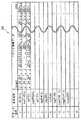
図16および図17において、シーケンスデータSd1およびSd2では、複数の楽器をMIDIチャンネルと称する複数のトラック(チャンネル)に割り当てることにより、各楽器に割り当てたトラック番号で各々の楽器を指定して、複数の楽器の動作を選択的に制御できるようにしている。つまり、シーケンスデータSd1およびSd2では、1つのトラック(チャンネル)が音楽演奏上の1パート(1つの楽器)に割り当てられて構成されている。シーケンスデータSd1およびSd2は、DSP34およびARAM35(音源)によって複数の楽器による演奏を行うために利用される。上記音源は、楽器それぞれに対応する音色を有しており、トラック毎に異なる音色を割り当てて、指定されたトラック番号に応じた音色の楽音を発生する。そして、上記音源は、CPU30から指示される演奏パラメータに基づいて指定された音程、音色、音量の楽音を指定された演奏テンポで発音する。 16 and 17, in the sequence data Sd1 and Sd2, by assigning a plurality of instruments to a plurality of tracks (channels) called MIDI channels, each instrument is designated by a track number assigned to each instrument. The operation of the instrument can be selectively controlled. That is, in the sequence data Sd1 and Sd2, one track (channel) is assigned to one part (one instrument) in music performance. The sequence data Sd1 and Sd2 are used to perform a performance with a plurality of musical instruments by the
具体的には、シーケンスデータSd1およびSd2は、16トラックのトラックデータTd101〜Td116およびTd201〜Td216をそれぞれ有している。各トラックには、トラック番号、楽器名称、およびトラック演奏データがそれぞれ記述されている。各トラックデータTdは、トラック番号「1」がフルート、トラック番号「2」がバイオリン、トラック番号「3」がピアノのように、各トラック番号に異なった楽器が割り当てられ、それぞれ対応するトラック演奏データが記述されている。トラック演奏データは、各楽器の発音開始(ノートオン)および発音停止(ノートオフ)を示す情報、音の高さを示す情報、発音の強さを示す情報等を含む音符的な情報である。DSP34およびARAM35は、トラック番号および演奏タイミングに応じたトラック演奏データとが指示されることによって、所定の音色の楽音を発生することができる。 Specifically, the sequence data Sd1 and Sd2 have 16 track data Td101 to Td116 and Td201 to Td216, respectively. In each track, a track number, an instrument name, and track performance data are described. Each track data Td is assigned a different instrument, such as a flute for track number “1”, a violin for track number “2” and a piano for track number “3”, and corresponding track performance data. Is described. The track performance data is musical note information including information indicating the start of sound generation (note on) and stop of sound generation (note off), information indicating the pitch, information indicating the strength of sound, and the like. The
シーケンスデータSd1およびSd2は、共に同じ楽曲を示すデータであるが、一例として奏法が異なったトラック演奏データが記述される。例えば、図16に示すシーケンスデータSd1は、各楽器(トラック)が音を滑らかに続けて発音する円滑奏法(レガート;Legato)によるトラック演奏データが記述されている。一方、図17に示すシーケンスデータSd2は、音楽的に適切な音符のみを1音符ずつ音を分離して各楽器が発音する分離奏法(スタッカート;Staccato)によるトラック演奏データが記述されている。 The sequence data Sd1 and Sd2 are data indicating the same music piece, but track performance data having different performance methods are described as an example. For example, the sequence data Sd1 shown in FIG. 16 describes track performance data by a smooth playing method (legato) in which each instrument (track) continuously produces sounds. On the other hand, the sequence data Sd2 shown in FIG. 17 describes track performance data according to a separated performance method (Staccato) in which only musically appropriate notes are separated into one note at a time, and each instrument produces a sound.
他のシーケンスデータSd1およびSd2の設定例として、シーケンスデータSd1に8ビートによるトラック演奏データを記述して、シーケンスデータSd2に16ビートによるトラック演奏データを記述する等、同じ楽曲でもビート数を変えたトラック演奏データを記述してもよい。また、シーケンスデータSd1に短調によるトラック演奏データを記述して、シーケンスデータSd2に長調によるトラック演奏データを記述する等、同じ楽曲でも曲調を変えたトラック演奏データを記述してもよい。シーケンスデータSd1およびSd2には、同じ楽曲でも楽曲の表現が異なるようなトラック演奏データがそれぞれ記述される。なお、1つの楽曲に対して3つ以上のシーケンスデータSdを設定してもかまわない。この場合、後述する選択シーケンステーブルを3区分以上に設定すれば、同様に本発明を実現することができる。 As an example of setting other sequence data Sd1 and Sd2, the number of beats is changed even for the same music, such as describing the track performance data with 8 beats in the sequence data Sd1 and describing the track performance data with 16 beats in the sequence data Sd2. Track performance data may be described. Alternatively, track performance data in which the same tone is changed may be described, for example, track performance data in minor key is described in sequence data Sd1 and track performance data in major key is described in sequence data Sd2. In the sequence data Sd1 and Sd2, track performance data in which the expression of music is different even for the same music is described. Note that three or more sequence data Sd may be set for one music piece. In this case, if the selection sequence table described later is set to three or more sections, the present invention can be similarly realized.
このように、1つの楽曲データDdは、奏法、ビート数、音調等が異なったシーケンスデータSdを含んでおり、各シーケンスデータSdは演奏対象となる楽器がそれぞれ異なったトラックデータTdを含んでいる。 Thus, one piece of music data Dd includes sequence data Sd having different performance styles, beat numbers, tones, and the like, and each sequence data Sd includes track data Td having different musical instruments to be played. .
トラック選択テーブルデータDeは、合成ベクトルの大きさにおけるピーク値に応じて選択されるトラック番号を示すテーブルデータであり、演奏対象となる楽曲毎に設定されている。以下、図18を参照して、トラック選択テーブルデータDeの一例について説明する。 The track selection table data De is table data indicating the track number selected according to the peak value in the size of the composite vector, and is set for each piece of music to be played. Hereinafter, an example of the track selection table data De will be described with reference to FIG.
図18において、トラック選択テーブルデータDeとして記憶されるトラック選択テーブルは、合成ベクトルピーク値Vpに対応する選択トラック番号が記述されている。例えば、合成ベクトルピーク値Vpが閾値V1未満の場合、トラック番号「1」、「3」、および「5」が選択されることがトラック選択テーブルに記述されている。合成ベクトルピーク値Vpが閾値V1以上で閾値V2未満の場合、トラック番号「1」〜「3」、「5」、「10」、および「12」が選択されることがトラック選択テーブルに記述されている。合成ベクトルピーク値Vpが閾値V2以上で閾値V3未満の場合、トラック番号「1」〜「3」、「5」、「7」、「8」、「10」、「12」、「15」、および「16」が選択されることがトラック選択テーブルに記述されている。そして、合成ベクトルピーク値Vpが閾値V3以上の場合、全てのトラック番号(つまり、トラック番号「1」〜「16」)が選択されることがトラック選択テーブルに記述されている。 In FIG. 18, the track selection table stored as the track selection table data De describes the selected track number corresponding to the combined vector peak value Vp. For example, the track selection table describes that the track numbers “1”, “3”, and “5” are selected when the combined vector peak value Vp is less than the threshold value V1. It is described in the track selection table that the track numbers “1” to “3”, “5”, “10”, and “12” are selected when the combined vector peak value Vp is greater than or equal to the threshold value V1 and less than the threshold value V2. ing. When the combined vector peak value Vp is not less than the threshold value V2 and less than the threshold value V3, the track numbers “1” to “3”, “5”, “7”, “8”, “10”, “12”, “15”, And “16” is selected in the track selection table. It is described in the track selection table that all track numbers (that is, track numbers “1” to “16”) are selected when the combined vector peak value Vp is equal to or greater than the threshold value V3.
シーケンス選択テーブルデータDfは、差分合成ベクトルの大きさにおけるピーク値に応じて選択されるシーケンス番号を示すテーブルデータであり、演奏対象となる楽曲毎に設定されている。以下、図19を参照して、シーケンス選択テーブルデータDfの一例について説明する。 The sequence selection table data Df is table data indicating a sequence number selected according to the peak value in the magnitude of the difference composite vector, and is set for each piece of music to be played. Hereinafter, an example of the sequence selection table data Df will be described with reference to FIG.
図19において、シーケンス選択テーブルデータDfとして記憶されるシーケンス選択テーブルは、差分合成ベクトルピーク値Dpに対応する選択シーケンス番号が記述されている。例えば、差分合成ベクトルピーク値Dpが閾値D1未満の場合、シーケンス番号「Sd1」が選択されることがシーケンス選択テーブルに記述されている。また、差分合成ベクトルピーク値Dpが閾値D1以上の場合、シーケンス番号「Sd2」が選択されることがシーケンス選択テーブルに記述されている。 In FIG. 19, the sequence selection table stored as the sequence selection table data Df describes the selected sequence number corresponding to the difference composite vector peak value Dp. For example, it is described in the sequence selection table that the sequence number “Sd1” is selected when the difference composite vector peak value Dp is less than the threshold value D1. Further, it is described in the sequence selection table that the sequence number “Sd2” is selected when the differential composite vector peak value Dp is equal to or greater than the threshold value D1.
画像データDgは、プレイヤキャラクタ画像データや他のキャラクタ画像データ等を含み、仮想ゲーム空間にプレイヤキャラクタや他のキャラクタを配置してゲーム画像を生成するためのデータである。 The image data Dg is data for generating a game image including player character image data, other character image data, and the like, and arranging the player character and other characters in the virtual game space.
次に、図20および図21を参照して、ゲーム装置3において行われる音楽演奏処理の詳細を説明する。なお、図20は、ゲーム装置3において実行される音楽演奏処理の流れの前半を示すフローチャートである。図21は、ゲーム装置3において実行される音楽演奏処理の流れの後半を示すフローチャートである。なお、図20および図21に示すフローチャートにおいては、ゲーム処理のうち、音楽演奏処理に関わる処理ついて説明し、本願発明と直接関連しない他のゲーム処理については詳細な説明を省略する。また、図20および図21では、CPU30が実行する各ステップを「S」と略称する。 Next, with reference to FIG. 20 and FIG. 21, the details of the music performance process performed in the
ゲーム装置3の電源が投入されると、ゲーム装置3のCPU30は、図示しないブートROMに記憶されている起動プログラムを実行し、これによってメインメモリ33等の各ユニットが初期化される。そして、光ディスク4に記憶されたゲームプログラムがメインメモリ33に読み込まれ、CPU30によって当該ゲームプログラムの実行が開始される。図20〜図21に示すフローチャートは、以上の処理が完了した後に行われる音楽演奏処理を示すフローチャートである。 When the power of the
図20において、CPU30は、音楽演奏処理を行うための初期設定を行い(ステップ51)、処理を次のステップに進める。例えば、CPU30は、初期設定として、音楽演奏処理処理を行う楽曲を選択して楽曲データDdから選択対象の楽曲データを抽出する。また、CPU30は、演奏対象とするシーケンスデータおよびトラックデータをデフォルト値に設定する。 In FIG. 20, the
次に、CPU30は、シーケンスのカウント処理を行い(ステップ52)、シーケンス終了か否かを判断する(ステップ53)。そして、演奏対象となっているシーケンスデータの最後までカウントされた場合、CPU30は、シーケンス終了と判断して、当該フローチャートによる処理を終了する。一方、CPU30は、演奏対象となっているシーケンスデータの途中までのカウントである場合、次のステップ54に処理を進める。ここで、上記ステップ52で行うカウント処理は、シーケンスデータ(図16、図17参照)からトラック演奏データを順番に読み出す際に、どのタイミングのトラック演奏データを読み出すのかを示すカウント値を設定する処理であり、設定される拍タイミングに応じてカウント値の進行が変化する。なお、後述により明らかとなるが、本実施形態ではプレイヤの操作に応じて演奏対象となるシーケンスデータが変化する。したがって、上記ステップ52で行うカウント処理で進行したカウント値は、演奏対象となりえる複数のシーケンスデータ(つまり、同じ楽曲データに所属するシーケンスデータ)を対象としており、複数のシーケンスデータに対するカウントが同時並行で進行することになる。 Next, the
ステップ54において、CPU30は、コントローラ7から受信した操作情報に含まれる各軸の加速度データを取得し、処理を次のステップに進める。そして、CPU30は、取得した加速度データを加速度データDaとしてメインメモリ33に記憶する。ここで、ステップ54で取得される加速度データには、加速度センサ701がX、Y、およびZ軸の3軸成分に分けてそれぞれ検出したX、Y、およびZ軸方向加速度データが含まれている。ここでは、通信部75は、所定の時間間隔(例えば5ms間隔)で操作情報をゲーム装置3へ送信しており、受信ユニット6に備える図示しないバッファに少なくとも加速度データが蓄えられる。そして、CPU30は、所定の音楽演奏処理周期毎やゲーム処理単位である1フレーム毎にバッファに蓄えられた加速度データを取得してメインメモリ33に格納する。なお、メインメモリ33に取得した最新の加速度データを格納する際、前回取得して格納された加速度データDaを少なくとも残すように、すなわち最新の2回取得分の加速度データが常に格納されているように加速度データDaが更新される。 In step 54, the
次に、CPU30は、上記ステップ54で取得したX軸方向加速度データDa1、Y軸方向加速度データDa2、およびZ軸方向加速度データDa3を用いて、合成ベクトルの大きさVを算出する(ステップ55)。具体的には、CPU30は、X軸方向加速度データDa1が示す加速度をXa、Y軸方向加速度データDa2が示す加速度をYa、およびZ軸方向加速度データDa3が示す加速度をZaとして、上記数式(1)を用いて大きさVを算出する。そして、CPU30は、算出した大きさVを合成ベクトル履歴データDbの最新データとして記録し(ステップ56)、処理を次のステップに進める。ここで、CPU30は、Y軸方向加速度データDa2がY軸正方向の加速度を示している場合、大きさV=0として記録する。これは、上述したように、拍子のタイミングで生じる加速度とは逆方向に生じた成分による大きさVのピークを除去するためであり、V=0として記録することによって後述するステップ61において各拍子のタイミングに応じたピーク値のみ抽出することができる。 Next, the
次に、CPU30は、上記ステップ54で取得したX軸方向加速度データDa1、Y軸方向加速度データDa2、およびZ軸方向加速度データDa3と、前回取得したX軸方向加速度データDa1、Y軸方向加速度データDa2、およびZ軸方向加速度データDa3とを用いて、各軸の加速度の差分を算出する(ステップ57)。そして、CPU30は、各軸の加速度の差分を用いて、差分合成ベクトルの大きさDを算出する(ステップ58)。具体的には、CPU30は、前回取得したX軸方向加速度データDa1が示す加速度をXa0、Y軸方向加速度データDa2が示す加速度をYa0、およびZ軸方向加速度データDa3が示す加速度をZa0として、上記数式(2)を用いて大きさDを算出する。そして、CPU30は、算出した大きさDを差分合成ベクトル履歴データDcの最新データとして記録し(ステップ59)、処理を次のステップに進める。 Next, the
図21に進み、CPU30は、合成ベクトル履歴データDbとして記録されている合成ベクトルの大きさVの履歴を参照して、合成ベクトルの大きさVのピークか否かを判定する(ステップ61)。なお、合成ベクトルの大きさVのピーク検出については、既に公知のピーク検出アルゴリズムを用いればよい。そして、CPU30は、合成ベクトルの大きさVのピークである場合(ステップ62でYes)、次のステップ63に処理を進める。一方、CPU30は、合成ベクトルの大きさVのピークでない場合(ステップ62でNo)、次のステップ68に処理を進める。 Proceeding to FIG. 21, the
ステップ63において、CPU30は、検出された合成ベクトルピーク値Vpに応じて、音量およびトラックデータを選択して、処理を次のステップに進める。CPU30は、例えば合成ベクトルピーク値Vpが相対的に大きいときに再生される楽曲の音量が大きくなるように、演奏パラメータの1つである演奏音量(ダイナミクス)を合成ベクトルピーク値Vpに応じて設定する。一例として、CPU30は、過去の合成ベクトルピーク値Vpの値を参照して、最新のピーク値Vpに所定の重み付けをした加重平均を取ることで演奏音量を算出する。 In step 63, the
上記ステップ63におけるトラックデータの選択については、例えば合成ベクトルピーク値Vpが取りうる数値範囲に対して、複数の閾値(例えば、3つの閾値V1、V2、V3;0<V1<V2<V3<取りうる最大値)が設定される。そして、それらの閾値と検出された合成ベクトルピーク値Vpとの関係に応じて、選択するトラックデータ(Td)が決定される。例えば、CPU30は、トラック選択テーブルデータDeから演奏対象となっている楽曲のトラック選択テーブル(図18)を参照し、合成ベクトルピーク値Vpに応じて選択するトラック番号を決定する。上述したように、各トラックデータTdは、異なった楽器がそれぞれ割り当てられ、その楽器に対応するトラック演奏データが記述されている。したがって、トラックデータを選択することによって、楽曲の演奏対象とする楽器数や種類を選択することになる。 With respect to the selection of the track data in step 63, for example, a plurality of threshold values (for example, three threshold values V1, V2, V3; 0 <V1 <V2 <V3 <take) with respect to a numerical range that the combined vector peak value Vp can take. The maximum possible value) is set. Then, the track data (Td) to be selected is determined according to the relationship between the threshold values and the detected combined vector peak value Vp. For example, the
ここで、合成ベクトルピーク値Vpは、プレイヤがコントローラ7を大きく速く振り動かすことによって、その値が上昇するパラメータである。したがって、図18に示した例のように、合成ベクトルピーク値Vpが大きくなるにしたがって選択されるトラック数を多くすることによって、プレイヤがコントローラ7を大きく速く振り動かすことに応じて演奏される楽器数や種類が増えることになる。したがって、コントローラ7を振り動かすことによって演奏される楽曲の表現が変化した印象をプレイヤに与えて、あたかもプレイヤが指揮をしているようなリアルな感覚を与えることができる。 Here, the combined vector peak value Vp is a parameter whose value increases when the player swings the
なお、上記ステップ63におけるトラックデータの選択は、選択トラックテーブルを参照することによって行われたが、他の態様でトラックデータが選択されてもかまわない。例えば、合成ベクトルピーク値Vpを変数として選択トラック数nが算出される数式を設定して、取得した合成ベクトルピーク値Vpに基づいて選択トラック数nを算出する。そして、演奏対象のシーケンスデータSdから選択トラック数nに応じた任意のトラックデータ、またはトラック番号「1」〜「n」までのトラックデータを選択してもかまわない。 Note that the selection of the track data in step 63 is performed by referring to the selected track table, but the track data may be selected in another manner. For example, an equation for calculating the selected track number n is set using the combined vector peak value Vp as a variable, and the selected track number n is calculated based on the acquired combined vector peak value Vp. Then, any track data corresponding to the selected track number n or track data from track numbers “1” to “n” may be selected from the sequence data Sd to be played.
次に、CPU30は、差分合成ベクトル履歴データDcとして記録されている差分合成ベクトルの大きさDの履歴を参照して、所定時間前(例えば、8フレーム前)から現在までに差分合成ベクトルの大きさDのピークがあるか否かを判定する(ステップ64)。なお、差分合成ベクトルの大きさDのピーク検出についても、既に公知のピーク検出アルゴリズムを用いればよい。そして、CPU30は、差分合成ベクトルの大きさDのピークがある場合(ステップ65でYes)、次のステップ66に処理を進める。一方、CPU30は、差分合成ベクトルの大きさDのピークでない場合(ステップ65でNo)、次のステップ70に処理を進める。 Next, the
ステップ66において、CPU30は、検出された差分合成ベクトルピーク値Dpに応じて、演奏対象とするシーケンスデータを選択して、次のステップ67に処理を進める。具体的には、例えば差分合成ベクトルピーク値Dpが取りうる数値範囲に対して、少なくとも1つの閾値D1が設定される。ここで、閾値D1は、予め設定された最大値D1maxと最小値D1minとの間でピーク値Vpに応じて線形に変化する。例えば、コントローラ7を振り動かす大きさを示すボリューム値Vmを、
Vm=Vp/(大きさVが取りうる最大値)
で算出して、閾値D1を
D1=D1min+(D1max−D1min)×Vm
として、最大値D1maxと最小値D1minとの間で閾値D1を変化させる。上述した図12Bのピーク値Dpと図13Bのピーク値Dpと差のように、コントローラ7を振り動かす大きさによってはピーク値Dpの差が表れないことがあるが、ピーク値Vpが相対的に小さいときに閾値D1の値を小さく変化させることによって、コントローラ7を振り動かすときのメリハリの強弱をピーク値Dpによって正確に判定することができる。In
Vm = Vp / (maximum value that size V can take)
And the threshold value D1 is calculated as follows: D1 = D1min + (D1max−D1min) × Vm
As described above, the threshold value D1 is changed between the maximum value D1max and the minimum value D1min. Like the difference between the peak value Dp of FIG. 12B and the peak value Dp of FIG. 13B described above, the difference in the peak value Dp may not appear depending on the magnitude of the swing of the
そして、CPU30は、閾値D1と検出された差分合成ベクトルピーク値Dpとの関係に応じて、選択するシーケンスデータ(Sd)を決定する。例えば、CPU30は、シーケンス選択テーブルデータDfから演奏対象となっている楽曲のシーケンス選択テーブル(図19)を参照し、差分合成ベクトルピーク値Dpに応じて選択するシーケンス番号を決定する。上述したように、各シーケンスデータSdは、共に同じ楽曲を示すデータであるが、奏法、ビート数、音調等が異なったトラック演奏データが記述されている。したがって、シーケンスデータを選択することによって、楽曲を演奏する奏法、ビート数、音調等を選択することになる。 And CPU30 determines the sequence data (Sd) to select according to the relationship between the threshold value D1 and the detected difference synthetic | combination vector peak value Dp. For example, the
ここで、差分合成ベクトルピーク値Dpは、プレイヤがコントローラ7を拍子のタイミングでメリハリをつけて振り動かすことによって、その値が上昇するパラメータである。例えば、図16、図17、および図19に示した例では、差分合成ベクトルピーク値Dpが大きくなると円滑奏法から分離奏法に変化するようにシーケンスデータが選択される。したがって、メリハリのある振り方でコントローラ7を振り動かすことによって演奏される楽曲の表現が変化した印象をプレイヤに与えて、あたかもプレイヤが指揮をしているようなリアルな感覚を与えることができる。 Here, the difference composite vector peak value Dp is a parameter whose value rises when the player swings the
一方、ステップ70において、CPU30は、差分合成ベクトル履歴データDcとして記録されている差分合成ベクトルの大きさDの履歴を参照して、所定時間前から現在までの差分合成ベクトルの大きさDの最大値に応じて、演奏シーケンスデータを選択して、次のステップ67に処理を進める。例えば、プレイヤによるコントローラ7の振り動かし方によっては、合成ベクトルピーク値Vpが検出される直前に差分合成ベクトルの大きさDのピークが表れないことがある。例えば、図14Bおよび図14Cに示すように、プレイヤがコントローラ7を小さく振り動かして各拍子をとるタイミングをやわらかくメリハリが少ない振り方をしたとき、差分合成ベクトルピーク値Vp5発生時点からピーク値Vp6発生時点までの期間には、差分合成ベクトルの大きさDのピークが表れていない。このような状態のときには、該当期間における大きさD最大値を採用して演奏シーケンスデータを選択する。なお、大きさDの最大値に応じて演奏シーケンスデータを選択する方法は、ピーク値Dpを用いて選択する方法と同様であるため、詳細な説明を省略する。 On the other hand, in
ステップ67において、CPU30は、前回取得した合成ベクトルの大きさVのピーク発生時点から今回取得した合成ベクトルの大きさVのピーク発生時点までの時間間隔(図11Cのt1、t2参照)を算出し、当該時間間隔を用いて演奏テンポを設定して、次のステップ68に処理を進める。具体的には、CPU30は、算出された時間間隔が相対的に長いときに再生される楽曲の演奏テンポが遅くなるように、演奏パラメータの1つである拍タイミングを設定する。一例として、CPU30は、過去に算出した時間間隔を参照して、最新の時間間隔に所定の重み付けをした加重平均を取ることで拍タイミングを算出する。 In
ステップ68において、CPU30は、設定されている演奏パラメータに基づいて制御し、現在選択されているシーケンスデータおよびトラックデータを演奏対象にして楽曲データDdを演奏して、処理を次のステップに進める。具体的には、CPU30は、現在の演奏パラメータによって、演奏音量および拍タイミング等を設定する。また、CPU30は、上記ステップ52のカウントされているカウント値に応じて、選択されているトラック演奏データから情報を読み出す。そして、音源(DSP34およびARAM35)は、読み出された各トラック演奏データに予め設定された音色を割り当て、演奏パラメータに基づいてスピーカ2aから音を再生する。これによって、プレイヤがコントローラ7を振り動かす動作に応じた所定の音色の楽曲が演奏される。 In
ここで、上記ステップ68では、プレイヤがコントローラ7を振り動かさなかった場合、シーケンスデータSdにおける拍の最後の時点で泊タイミング(演奏テンポ)を0にして楽曲演奏を停止させてもよい。また、演奏停止状態からコントローラ7を振り動かす動作が開始された場合、合成ベクトルの大きさVがピークを示した時点とシーケンスデータSdにおける拍の出だしとを一致させて楽曲演奏を開始してもよい。 Here, in
次に、CPU30は、例えば現在選択されているトラックデータに応じて演奏対象のキャラクタを設定して当該キャラクタが演奏している様子を表現し、プレイヤキャラクタPCが拍子タイミングに応じて指揮棒を振る様子を表現したゲーム画像(図8、図9参照)を生成してモニタ2に表示する(ステップ69)。そして、CPU30は、上記ステップ52に戻って処理を繰り返す。 Next, for example, the
このように、複数のトラックデータを有する楽曲に対して、加速度センサが検出した加速度の大きさに応じて演奏対象とするトラックデータを変化させるため、プレイヤがコントローラ7を振り動かす動作に応じて音楽の演奏の内容を変化させることができる。例えば、各トラックデータに対して異なった楽器を割り当てることによって、演奏対象とする楽器種を変化させることができるため、多様な演奏変化を生じさせてプレイヤにあたかも指揮棒を振って指揮しているような娯楽環境を提供することができる。また、複数のトラックデータを有するシーケンスデータを複数設定された楽曲に対して、加速度センサが検出した加速度の大きさに応じて演奏対象とするシーケンスデータを変化させる。例えば、各シーケンスデータに奏法、ビート数、曲調等が異なった演奏データを記述することによって、プレイヤがコントローラ7を振り動かす動作に応じて音楽の表現を変化させることができる。したがって、さらに多様な演奏変化を生じさせることが可能となる。 In this way, for music having a plurality of track data, the track data to be played is changed in accordance with the magnitude of the acceleration detected by the acceleration sensor. The contents of the performance can be changed. For example, by assigning a different instrument to each track data, it is possible to change the type of musical instrument to be played, so that various performance changes occur and the player is commanded by waving a command stick. Such an entertainment environment can be provided. In addition, the sequence data to be played is changed according to the magnitude of the acceleration detected by the acceleration sensor for the music set with a plurality of sequence data having a plurality of track data. For example, by describing performance data having different performance styles, beat numbers, tunes, etc. in each sequence data, the expression of music can be changed in accordance with the motion of the player swinging the
なお、上記ステップ66やステップ70では、検出された差分合成ベクトルピーク値Dpや大きさDの最大値に応じて、演奏対象とするシーケンスデータを変更する処理を行っていたが、演奏対象とするトラックデータを変更してもかまわない。技術的には、図15〜図17に示すようにシーケンスデータSdがトラックデータ群を含んでいることから、複数のシーケンスデータから1つのシーケンスデータを選択することは、複数のトラックデータ群から1つのトラックデータ群を選択することと同意である。例えば、図16等に示したシーケンスデータSdのように複数のトラックデータが含まれる場合、当該トラックデータを複数のトラックデータ群に区別して何れかのトラックデータ群を選択する。そして、上記ステップ63で選択されたトラックデータを、選択されたトラックデータ群に属するトラックデータのみに制限する、または選択されたトラックデータ群に属するトラックデータに所定の方式を用いて変更する、または上記ステップ63において選択されたトラックデータ群から演奏対象のトラックデータを選択する等を行って演奏対象のトラックデータを決定する。このように、音楽の表現が異なるように構成されたシーケンスデータと同様に、トラックデータに対して音楽の表現が互いに異なる複数のトラックデータ群を構成することによって、同様に本発明を実現することができる。 In
また、上述した楽曲データDdは、MIDI形式の音源制御データで構成された例を説明したが、他の形式のデータで構成してもかまわない。例えば、各トラックデータに含まれるトラック演奏データを、それぞれ各トラックに割り当てられた楽器の生演奏を録音すること等によって得られる波形情報(ストリーミング情報)やPCM(Pulse Code Modulation)データで構成してもかまわない。この場合、演奏テンポの制御が困難となるが、音の高さを変えずに演奏テンポを変える既に周知のタイムコンプレッションの技術を用いれば、同様にコントローラ7の動作によって得られる拍タイミングに応じた演奏テンポ制御が可能となる。 Further, although the above-described music data Dd has been described as being composed of sound source control data in the MIDI format, it may be composed of data in other formats. For example, the track performance data included in each track data is composed of waveform information (streaming information) or PCM (Pulse Code Modulation) data obtained by recording a live performance of the musical instrument assigned to each track. It doesn't matter. In this case, although it becomes difficult to control the performance tempo, if the already known time compression technique for changing the performance tempo without changing the pitch is used, the beat tempo obtained according to the operation of the
また、コントローラ7で検出されたY軸方向の加速度がY軸正方向である場合、合成ベクトルの大きさVを0とすることによって、拍子のタイミングで生じる加速度とは逆方向に生じた成分を除去したが、他の軸成分における正負方向の加速度検出や複数軸成分における正負方向の加速度検出によって同様の処理を行ってもかまわない。 Further, when the acceleration in the Y-axis direction detected by the
また、コントローラ7に設けられた加速度センサ701は、互いに直交する3軸成分に分けてそれぞれ検出して出力する3軸加速度センサを用いて説明したが、少なくとも直交する2軸成分をそれぞれ検出する加速度センサを用いれば本発明を実現することができる。例えば、コントローラ7が配置された3次元空間における加速度をX軸およびY軸(図3、図4参照)の2軸成分に分けてそれぞれ検出して出力する加速度センサを用いても、プレイヤが上下左右方向にコントローラ7を指揮棒のように振り動かす動作の判定を行うことができる。さらに、1軸方向のみの加速度を検出する加速度センサを用いても本発明を実現することができる。例えば、コントローラ7が配置された3次元空間における加速度をY軸(図3、図4参照)成分のみ検出して出力する加速度センサを用いても、プレイヤが上下方向にコントローラ7を指揮棒のように振り動かす動作の判定を行うことができる。 Further, although the
また、上述した説明では、コントローラ7とゲーム装置3とが無線通信によって接続された態様を用いたが、コントローラ7とゲーム装置3とがケーブルを介して電気的に接続されてもかまわない。この場合、コントローラ7に接続されたケーブルをゲーム装置3の接続端子に接続する。 In the above description, the
また、コントローラ7から無線送信される送信データを受信する受信手段として、ゲーム装置3の接続端子に接続された受信ユニット6を用いて説明したが、ゲーム装置3の本体内部に設けられた受信モジュールによって当該受信手段を構成してもかまわない。この場合、受信モジュールが受信した送信データは、所定のバスを介してCPU30に出力される。 Further, the
また、上述したコントローラ7の形状や、それらに設けられている操作部72の形状、数、および設置位置等は、単なる一例に過ぎず他の形状、数、および設置位置であっても、本発明を実現できることは言うまでもない。また、コントローラ7における撮像情報演算部74の位置(撮像情報演算部74の光入射口)は、ハウジング71の前面でなくてもよく、ハウジング71の外部から光を取り入れることができれば他の面に設けられてもかまわない。 In addition, the shape of the
本発明に係る音楽演奏プログラムおよび音楽演奏装置は、複数のトラックデータを有する楽曲に対して、加速度センサが検出した加速度の大きさに応じて演奏対象とするトラックデータを変化させることができ、入力装置等の動きに応じて音楽を演奏する装置やプログラムとして有用である。 The music performance program and the music performance device according to the present invention can change track data to be performed on music having a plurality of track data according to the magnitude of acceleration detected by the acceleration sensor, It is useful as a device or program for playing music according to the movement of the device or the like.
1…ゲームシステム
2…モニタ
2a…スピーカ
3…ゲーム装置
30…CPU
31…メモリコントローラ
32…GPU
33…メインメモリ
34…DSP
35…ARAM
36…コントローラI/F
37…ビデオI/F
38…外部メモリI/F
39…オーディオI/F
40…ディスクドライブ
41…ディスクI/F
4…光ディスク
5…外部メモリカード
6…受信ユニット
7…コントローラ
71…ハウジング
72…操作部
73…コネクタ
74…撮像情報演算部
741…赤外線フィルタ
742…レンズ
743…撮像素子
744…画像処理回路
75…通信部
751…マイコン
752…メモリ
753…無線モジュール
754…アンテナ
700…基板
701…加速度センサ
702…LED
703…水晶振動子
704…バイブレータ
705…電池
8…マーカ
DESCRIPTION OF
31 ...
33 ...
35 ... ARAM
36 ... Controller I / F
37 ... Video I / F
38 ... External memory I / F
39 ... Audio I / F
40 ...
DESCRIPTION OF
703 ...
Claims (12)
Translated fromJapanese前記コンピュータに、
前記加速度センサから出力される加速度データを取得する加速度データ取得ステップと、
取得した加速度データを用いて、加速度の大きさを算出する加速度算出ステップと、
算出された加速度の大きさに基づいて、記憶手段に記憶された複数のトラックデータを含む楽曲データから演奏対象とするトラックデータを少なくとも1つ選択するトラックデータ選択ステップと、
前記トラックデータ選択ステップで選択されたトラックデータに基づいて、音響発生機器から発生する楽音を制御するためのデータを出力する音楽演奏ステップとを実行させる、音楽演奏プログラム。A music performance program executed by a computer of a device operated in accordance with acceleration detected by an input device including an acceleration sensor for detecting acceleration in at least one axis direction,
In the computer,
An acceleration data acquisition step of acquiring acceleration data output from the acceleration sensor;
Using the acquired acceleration data, an acceleration calculating step for calculating the magnitude of acceleration;
A track data selection step of selecting at least one track data to be played from music data including a plurality of track data stored in the storage means based on the calculated magnitude of acceleration;
A music performance program for executing a music performance step of outputting data for controlling a musical sound generated from a sound generator based on the track data selected in the track data selection step.
前記トラックデータ選択ステップでは、前記加速度ピーク値検出ステップで検出された加速度の大きさのピーク値に基づいて、演奏対象とするトラックデータが選択される、請求項1に記載の音楽演奏プログラム。Using the history of the magnitude of acceleration calculated in the acceleration calculating step, causing the computer to further execute an acceleration peak value detecting step of detecting a peak value of the magnitude of the acceleration,
The music performance program according to claim 1, wherein in the track data selection step, track data to be played is selected based on a peak value of the magnitude of acceleration detected in the acceleration peak value detection step.
前記トラックデータ選択ステップでは、前記差分算出ステップで算出された加速度の差分に基づいて、演奏対象とするトラックデータが選択される、請求項1に記載の音楽演奏プログラム。The acceleration calculating step includes a difference calculating step of calculating a difference between the acceleration calculated using the previously acquired acceleration data and the acceleration calculated using the acceleration data acquired this time,
The music performance program according to claim 1, wherein in the track data selection step, track data to be played is selected based on the difference in acceleration calculated in the difference calculation step.
前記トラックデータ選択ステップでは、前記加速度差分ピーク値検出ステップで検出された加速度の差分のピーク値に基づいて、演奏対象とするトラックデータが選択される、請求項3に記載の音楽演奏プログラム。Using the history of acceleration differences calculated in the difference calculating step, further causing the computer to execute an acceleration difference peak value detecting step of detecting a peak value of the acceleration difference,
4. The music performance program according to claim 3, wherein in the track data selection step, track data to be played is selected based on a peak value of an acceleration difference detected in the acceleration difference peak value detection step.
前記加速度算出ステップでは、今回取得した加速度データから算出した加速度の大きさ、および前回取得した加速度データを用いて算出した加速度と今回取得した加速度データを用いて算出した加速度との差分が算出され、
前記音楽演奏プログラムは、
前記加速度算出ステップで算出された加速度の大きさの履歴を用いて、当該加速度の大きさのピーク値を検出する加速度ピーク値検出ステップと、
前記加速度算出ステップで算出された加速度の差分の履歴を用いて、当該加速度の差分のピーク値を検出する加速度差分ピーク値検出ステップとを、さらに前記コンピュータに実行させ、
前記トラックデータ選択ステップでは、前記加速度差分ピーク値検出ステップで検出された加速度の差分のピーク値に基づいて演奏対象とするトラックデータ群が選択され、前記加速度ピーク値検出ステップで検出された加速度の大きさのピーク値に基づいて演奏対象のトラックデータ群から演奏対象のトラックデータが選択される、請求項1に記載の音楽演奏プログラム。The music data includes a plurality of track data groups each consisting of different track data,
In the acceleration calculation step, the magnitude of the acceleration calculated from the acceleration data acquired this time, and the difference between the acceleration calculated using the acceleration data acquired last time and the acceleration calculated using the acceleration data acquired this time are calculated.
The music performance program is
An acceleration peak value detection step of detecting a peak value of the acceleration magnitude using the history of the magnitude of acceleration calculated in the acceleration calculation step;
Using the history of acceleration differences calculated in the acceleration calculating step, the acceleration difference peak value detecting step for detecting the peak value of the acceleration difference is further executed by the computer,
In the track data selection step, a track data group to be played is selected based on the peak value of the acceleration difference detected in the acceleration difference peak value detection step, and the acceleration data detected in the acceleration peak value detection step is selected. The music performance program according to claim 1, wherein track data to be played is selected from a track data group to be played based on a peak value of the size.
前記加速度算出ステップでは、取得した加速度データを用いて、前記複数軸方向それぞれの加速度ベクトルを合成した合成ベクトルの大きさが算出される、請求項1に記載の音楽演奏プログラム。The acceleration sensor detects accelerations in a plurality of axial directions orthogonal to the input device;
The music performance program according to claim 1, wherein in the acceleration calculation step, a magnitude of a combined vector obtained by combining the acceleration vectors in the plurality of axial directions is calculated using the acquired acceleration data.
前記差分算出ステップでは、前回取得した加速度データを用いて算出した加速度と今回取得した加速度データを用いて算出した加速度との差分を前記複数軸方向それぞれに算出し、当該複数軸方向それぞれの差分ベクトルを合成した差分合成ベクトルの大きさが加速度の差分として算出される、請求項3に記載の音楽演奏プログラム。The acceleration sensor detects accelerations in a plurality of axial directions orthogonal to the input device;
In the difference calculating step, a difference between the acceleration calculated using the acceleration data acquired last time and the acceleration calculated using the acceleration data acquired this time is calculated for each of the plurality of axis directions, and a difference vector for each of the plurality of axis directions is calculated. The music performance program according to claim 3, wherein the magnitude of the difference synthesis vector obtained by synthesizing is calculated as an acceleration difference.
前記トラックデータに割り当てられた楽器をそれぞれ仮想ゲーム世界に配置し、前記トラックデータ選択ステップで選択されたトラックデータに割り当てられた楽器のみが演奏されるアクションを表示装置に表示する表示処理ステップを、さらに前記コンピュータに実行させる、請求項1に記載の音楽演奏プログラム。Different instruments are assigned to the plurality of track data,
A display processing step of placing each instrument assigned to the track data in a virtual game world and displaying on the display device an action in which only the instrument assigned to the track data selected in the track data selection step is played; The music performance program according to claim 1, further executed by the computer.
前記楽曲データに含まれる複数のトラックデータは、それぞれ前記音源の制御データで構成され、
前記音楽演奏ステップでは、前記トラックデータ選択ステップで選択されたトラックデータに記述された制御データが出力されて前記音源が制御される、請求項1に記載の音楽演奏プログラム。The apparatus includes a sound source that generates a musical sound from a sound generating device,
The plurality of track data included in the music data are each composed of control data of the sound source,
2. The music performance program according to claim 1, wherein in the music performance step, control data described in the track data selected in the track data selection step is output to control the sound source.
前記加速度センサから出力される加速度データを取得する加速度データ取得手段と、
取得した加速度データを用いて、加速度の大きさを算出する加速度算出手段と、
算出された加速度の大きさに基づいて、記憶手段に記憶された複数のトラックデータを含む楽曲データから演奏対象とするトラックデータを少なくとも1つ選択するトラックデータ選択手段と、
前記トラックデータ選択手段が選択したトラックデータに基づいて、音響発生機器から発生する楽音を制御するためのデータを出力する音楽演奏手段とを備える、音楽演奏装置。
A music performance device operated according to acceleration detected by an input device including an acceleration sensor that detects acceleration in at least one axial direction,
Acceleration data acquisition means for acquiring acceleration data output from the acceleration sensor;
Acceleration calculation means for calculating the magnitude of acceleration using the acquired acceleration data;
Track data selection means for selecting at least one track data to be played from music data including a plurality of track data stored in the storage means based on the magnitude of the calculated acceleration;
A music performance device comprising: music performance means for outputting data for controlling musical sounds generated from a sound generator based on the track data selected by the track data selection means.
Priority Applications (3)
| Application Number | Priority Date | Filing Date | Title |
|---|---|---|---|
| JP2006120926AJP4757089B2 (en) | 2006-04-25 | 2006-04-25 | Music performance program and music performance apparatus |
| US11/542,243US7491879B2 (en) | 2006-04-25 | 2006-10-04 | Storage medium having music playing program stored therein and music playing apparatus therefor |
| EP06020833AEP1850318B1 (en) | 2006-04-25 | 2006-10-04 | Storage medium having music playing program stored therein and music playing apparatus thereof |
Applications Claiming Priority (1)
| Application Number | Priority Date | Filing Date | Title |
|---|---|---|---|
| JP2006120926AJP4757089B2 (en) | 2006-04-25 | 2006-04-25 | Music performance program and music performance apparatus |
Related Child Applications (1)
| Application Number | Title | Priority Date | Filing Date |
|---|---|---|---|
| JP2010183922ADivisionJP5036010B2 (en) | 2010-08-19 | 2010-08-19 | Music performance program, music performance device, music performance system, and music performance method |
Publications (2)
| Publication Number | Publication Date |
|---|---|
| JP2007293042Atrue JP2007293042A (en) | 2007-11-08 |
| JP4757089B2 JP4757089B2 (en) | 2011-08-24 |
Family
ID=38375769
Family Applications (1)
| Application Number | Title | Priority Date | Filing Date |
|---|---|---|---|
| JP2006120926AActiveJP4757089B2 (en) | 2006-04-25 | 2006-04-25 | Music performance program and music performance apparatus |
Country Status (3)
| Country | Link |
|---|---|
| US (1) | US7491879B2 (en) |
| EP (1) | EP1850318B1 (en) |
| JP (1) | JP4757089B2 (en) |
Cited By (4)
| Publication number | Priority date | Publication date | Assignee | Title |
|---|---|---|---|---|
| JP2011507098A (en)* | 2007-12-12 | 2011-03-03 | イマージョン コーポレーション | Method and apparatus for distributing haptic synchronization signals |
| WO2014118922A1 (en)* | 2013-01-30 | 2014-08-07 | 株式会社スクウェア・エニックス | Game program |
| US9079058B2 (en) | 2009-10-23 | 2015-07-14 | Sony Corporation | Motion coordination operation device and method, program, and motion coordination reproduction system |
| KR20180067964A (en)* | 2016-12-13 | 2018-06-21 | 계명대학교 산학협력단 | Conducting game apparatus based on user gesture and conducting game method using the same |
Families Citing this family (29)
| Publication number | Priority date | Publication date | Assignee | Title |
|---|---|---|---|---|
| US9229540B2 (en) | 2004-01-30 | 2016-01-05 | Electronic Scripting Products, Inc. | Deriving input from six degrees of freedom interfaces |
| US7961909B2 (en) | 2006-03-08 | 2011-06-14 | Electronic Scripting Products, Inc. | Computer interface employing a manipulated object with absolute pose detection component and a display |
| JP4679429B2 (en)* | 2006-04-27 | 2011-04-27 | 任天堂株式会社 | Sound output program and sound output device |
| JP4679431B2 (en)* | 2006-04-28 | 2011-04-27 | 任天堂株式会社 | Sound output control program and sound output control device |
| JP4916762B2 (en)* | 2006-05-02 | 2012-04-18 | 任天堂株式会社 | GAME PROGRAM AND GAME DEVICE |
| US7479595B2 (en)* | 2006-05-09 | 2009-01-20 | Concertizer Enterprises, Inc. | Method and system for processing music on a computer device |
| US20080223199A1 (en)* | 2007-03-16 | 2008-09-18 | Manfred Clynes | Instant Rehearseless Conducting |
| US7842875B2 (en)* | 2007-10-19 | 2010-11-30 | Sony Computer Entertainment America Inc. | Scheme for providing audio effects for a musical instrument and for controlling images with same |
| US9844730B1 (en)* | 2008-06-16 | 2017-12-19 | Disney Enterprises, Inc. | Method and apparatus for an interactive dancing video game |
| SG162624A1 (en)* | 2008-12-09 | 2010-07-29 | Creative Tech Ltd | A method and device for modifying playback of digital music content |
| EP2396711A2 (en)* | 2009-02-13 | 2011-12-21 | Movea S.A | Device and process interpreting musical gestures |
| FR2942345A1 (en)* | 2009-02-13 | 2010-08-20 | Movea | Gesture interpreting device for player of e.g. guitar, has gesture interpretation and analyze sub-module assuring gesture detection confirmation function by comparing variation between two values in sample of signal with threshold value |
| US20100313133A1 (en)* | 2009-06-08 | 2010-12-09 | Microsoft Corporation | Audio and position control of user interface |
| US20110136574A1 (en)* | 2009-12-03 | 2011-06-09 | Harris Technology, Llc | Interactive music game |
| CN102125760B (en)* | 2010-01-14 | 2014-04-30 | 鸿富锦精密工业(深圳)有限公司 | Game drum |
| US20110252951A1 (en)* | 2010-04-20 | 2011-10-20 | Leavitt And Zabriskie Llc | Real time control of midi parameters for live performance of midi sequences |
| JP5029732B2 (en)* | 2010-07-09 | 2012-09-19 | カシオ計算機株式会社 | Performance device and electronic musical instrument |
| TW201237741A (en)* | 2011-03-08 | 2012-09-16 | Univ Tamkang | Interactive sound and light art device with wireless transmission and sensing capability |
| CN102290045B (en)* | 2011-05-13 | 2013-05-01 | 北京瑞信在线系统技术有限公司 | Method and device for controlling music rhythm and mobile terminal |
| JP2013182195A (en)* | 2012-03-02 | 2013-09-12 | Casio Comput Co Ltd | Musical performance device and program |
| JP6127367B2 (en) | 2012-03-14 | 2017-05-17 | カシオ計算機株式会社 | Performance device and program |
| JP6024136B2 (en)* | 2012-03-15 | 2016-11-09 | カシオ計算機株式会社 | Performance device, performance method and program |
| WO2014058835A1 (en)* | 2012-10-08 | 2014-04-17 | Stc.Unm | System and methods for simulating real-time multisensory output |
| KR20170019651A (en)* | 2015-08-12 | 2017-02-22 | 삼성전자주식회사 | Method and electronic device for providing sound |
| US11577159B2 (en) | 2016-05-26 | 2023-02-14 | Electronic Scripting Products Inc. | Realistic virtual/augmented/mixed reality viewing and interactions |
| JP7140465B2 (en)* | 2016-06-10 | 2022-09-21 | 任天堂株式会社 | Game program, information processing device, information processing system, game processing method |
| DE102017003049A1 (en) | 2017-03-23 | 2018-09-27 | Martina Linden | Device for promoting movement by selecting and playing back audio files as a function of the movement |
| JP7081921B2 (en)* | 2017-12-28 | 2022-06-07 | 株式会社バンダイナムコエンターテインメント | Programs and game equipment |
| JP7081922B2 (en) | 2017-12-28 | 2022-06-07 | 株式会社バンダイナムコエンターテインメント | Programs, game consoles and methods for running games |
Citations (10)
| Publication number | Priority date | Publication date | Assignee | Title |
|---|---|---|---|---|
| JPH08305355A (en)* | 1995-05-09 | 1996-11-22 | Yamaha Corp | Automatic performance controller |
| JP2001195060A (en)* | 2000-01-11 | 2001-07-19 | Yamaha Corp | Musical performance interface |
| JP2002023742A (en)* | 2000-07-12 | 2002-01-25 | Yamaha Corp | Sounding control system, operation unit and electronic percussion instrument |
| JP2002196760A (en)* | 2001-10-22 | 2002-07-12 | Yamaha Corp | Musical sound generator |
| JP2003084779A (en)* | 2001-09-07 | 2003-03-19 | Yamaha Corp | Karaoke system |
| JP2004029847A (en)* | 2003-08-08 | 2004-01-29 | Yamaha Corp | Multimedia controller |
| JP2004029720A (en)* | 2003-02-24 | 2004-01-29 | Yamaha Corp | Information display method |
| JP2004177686A (en)* | 2002-11-27 | 2004-06-24 | Toyota Motor Corp | A device for recognizing the movement of a baton and a musical instrument playing robot |
| JP2005114537A (en)* | 2003-10-07 | 2005-04-28 | National Institute Of Advanced Industrial & Technology | Walking motion detection processing device and walking motion detection processing method |
| JP2005300629A (en)* | 2004-04-07 | 2005-10-27 | Yamaha Corp | Performance data editing device and program |
Family Cites Families (30)
| Publication number | Priority date | Publication date | Assignee | Title |
|---|---|---|---|---|
| JPS62143124A (en) | 1985-12-17 | 1987-06-26 | Agency Of Ind Science & Technol | Display mark moving system |
| US4839838A (en)* | 1987-03-30 | 1989-06-13 | Labiche Mitchell | Spatial input apparatus |
| US5005459A (en)* | 1987-08-14 | 1991-04-09 | Yamaha Corporation | Musical tone visualizing apparatus which displays an image of an animated object in accordance with a musical performance |
| US5440326A (en)* | 1990-03-21 | 1995-08-08 | Gyration, Inc. | Gyroscopic pointer |
| US5059958A (en)* | 1990-04-10 | 1991-10-22 | Jacobs Jordan S | Manually held tilt sensitive non-joystick control box |
| US5128671A (en)* | 1990-04-12 | 1992-07-07 | Ltv Aerospace And Defense Company | Control device having multiple degrees of freedom |
| JPH06161440A (en) | 1992-11-24 | 1994-06-07 | Sony Corp | Automatic playing device |
| US5913727A (en)* | 1995-06-02 | 1999-06-22 | Ahdoot; Ned | Interactive movement and contact simulation game |
| US5702323A (en)* | 1995-07-26 | 1997-12-30 | Poulton; Craig K. | Electronic exercise enhancer |
| US5920024A (en)* | 1996-01-02 | 1999-07-06 | Moore; Steven Jerome | Apparatus and method for coupling sound to motion |
| ES2231856T3 (en) | 1996-03-05 | 2005-05-16 | Sega Enterprises, Ltd. | CONTROLLER AND EXTENSION UNIT FOR THE CONTROLLER. |
| US6072467A (en)* | 1996-05-03 | 2000-06-06 | Mitsubishi Electric Information Technology Center America, Inc. (Ita) | Continuously variable control of animated on-screen characters |
| JP2000308756A (en) | 1999-04-27 | 2000-11-07 | Taito Corp | Input controller of game device |
| US6545661B1 (en)* | 1999-06-21 | 2003-04-08 | Midway Amusement Games, Llc | Video game system having a control unit with an accelerometer for controlling a video game |
| US6375572B1 (en)* | 1999-10-04 | 2002-04-23 | Nintendo Co., Ltd. | Portable game apparatus with acceleration sensor and information storage medium storing a game progam |
| US6315673B1 (en)* | 1999-10-05 | 2001-11-13 | Midway Amusement Games Llc | Motion simulator for a video game |
| JP3646599B2 (en) | 2000-01-11 | 2005-05-11 | ヤマハ株式会社 | Playing interface |
| EP1860642A3 (en)* | 2000-01-11 | 2008-06-11 | Yamaha Corporation | Apparatus and method for detecting performer´s motion to interactively control performance of music or the like |
| JP4694705B2 (en)* | 2001-02-23 | 2011-06-08 | ヤマハ株式会社 | Music control system |
| JP2003062341A (en)* | 2001-08-22 | 2003-03-04 | Nintendo Co Ltd | Game system, puzzle game program, and recording medium with program recorded thereon |
| JP2003325972A (en)* | 2002-05-17 | 2003-11-18 | Nintendo Co Ltd | Game device changing sound and image in association with tilt operation, and game program therefor |
| JP3902508B2 (en)* | 2002-05-20 | 2007-04-11 | 任天堂株式会社 | Game system and game program |
| JP4144269B2 (en)* | 2002-06-28 | 2008-09-03 | ヤマハ株式会社 | Performance processor |
| JP3867630B2 (en)* | 2002-07-19 | 2007-01-10 | ヤマハ株式会社 | Music playback system, music editing system, music editing device, music editing terminal, music playback terminal, and music editing device control method |
| JP2004086067A (en)* | 2002-08-28 | 2004-03-18 | Nintendo Co Ltd | Speech generator and speech generation program |
| KR100981691B1 (en)* | 2003-02-12 | 2010-09-14 | 코닌클리케 필립스 일렉트로닉스 엔.브이. | Audio playback apparatus, methods, computer readable recording media |
| US6969795B2 (en)* | 2003-11-12 | 2005-11-29 | Schulmerich Carillons, Inc. | Electronic tone generation system and batons therefor |
| US20060060068A1 (en)* | 2004-08-27 | 2006-03-23 | Samsung Electronics Co., Ltd. | Apparatus and method for controlling music play in mobile communication terminal |
| JP2006337505A (en)* | 2005-05-31 | 2006-12-14 | Sony Corp | Musical player and processing control method |
| US7728214B2 (en)* | 2005-11-23 | 2010-06-01 | Microsoft Corporation | Using music to influence a person's exercise performance |
- 2006
- 2006-04-25JPJP2006120926Apatent/JP4757089B2/enactiveActive
- 2006-10-04USUS11/542,243patent/US7491879B2/enactiveActive
- 2006-10-04EPEP06020833Apatent/EP1850318B1/enactiveActive
Patent Citations (10)
| Publication number | Priority date | Publication date | Assignee | Title |
|---|---|---|---|---|
| JPH08305355A (en)* | 1995-05-09 | 1996-11-22 | Yamaha Corp | Automatic performance controller |
| JP2001195060A (en)* | 2000-01-11 | 2001-07-19 | Yamaha Corp | Musical performance interface |
| JP2002023742A (en)* | 2000-07-12 | 2002-01-25 | Yamaha Corp | Sounding control system, operation unit and electronic percussion instrument |
| JP2003084779A (en)* | 2001-09-07 | 2003-03-19 | Yamaha Corp | Karaoke system |
| JP2002196760A (en)* | 2001-10-22 | 2002-07-12 | Yamaha Corp | Musical sound generator |
| JP2004177686A (en)* | 2002-11-27 | 2004-06-24 | Toyota Motor Corp | A device for recognizing the movement of a baton and a musical instrument playing robot |
| JP2004029720A (en)* | 2003-02-24 | 2004-01-29 | Yamaha Corp | Information display method |
| JP2004029847A (en)* | 2003-08-08 | 2004-01-29 | Yamaha Corp | Multimedia controller |
| JP2005114537A (en)* | 2003-10-07 | 2005-04-28 | National Institute Of Advanced Industrial & Technology | Walking motion detection processing device and walking motion detection processing method |
| JP2005300629A (en)* | 2004-04-07 | 2005-10-27 | Yamaha Corp | Performance data editing device and program |
Cited By (6)
| Publication number | Priority date | Publication date | Assignee | Title |
|---|---|---|---|---|
| JP2011507098A (en)* | 2007-12-12 | 2011-03-03 | イマージョン コーポレーション | Method and apparatus for distributing haptic synchronization signals |
| US9079058B2 (en) | 2009-10-23 | 2015-07-14 | Sony Corporation | Motion coordination operation device and method, program, and motion coordination reproduction system |
| WO2014118922A1 (en)* | 2013-01-30 | 2014-08-07 | 株式会社スクウェア・エニックス | Game program |
| JPWO2014118922A1 (en)* | 2013-01-30 | 2017-01-26 | 株式会社スクウェア・エニックス | Game program |
| KR20180067964A (en)* | 2016-12-13 | 2018-06-21 | 계명대학교 산학협력단 | Conducting game apparatus based on user gesture and conducting game method using the same |
| KR101895691B1 (en) | 2016-12-13 | 2018-09-05 | 계명대학교 산학협력단 | Conducting game apparatus based on user gesture and conducting game method using the same |
Also Published As
| Publication number | Publication date |
|---|---|
| US20070256546A1 (en) | 2007-11-08 |
| EP1850318A2 (en) | 2007-10-31 |
| US7491879B2 (en) | 2009-02-17 |
| EP1850318A3 (en) | 2010-07-07 |
| EP1850318B1 (en) | 2012-08-08 |
| JP4757089B2 (en) | 2011-08-24 |
Similar Documents
| Publication | Publication Date | Title |
|---|---|---|
| JP4757089B2 (en) | Music performance program and music performance apparatus | |
| US8246460B2 (en) | Game system | |
| JP4679431B2 (en) | Sound output control program and sound output control device | |
| US10384129B2 (en) | System and method for detecting moment of impact and/or strength of a swing based on accelerometer data | |
| JP5173174B2 (en) | GAME DEVICE, GAME PROGRAM, GAME SYSTEM, AND GAME PROCESSING METHOD | |
| US8858330B2 (en) | Music video game with virtual drums | |
| US9199169B2 (en) | Computer-readable storage medium and game apparatus | |
| JP5812663B2 (en) | Music performance program, music performance device, music performance system, and music performance method | |
| JP2008099755A (en) | GAME PROGRAM AND GAME DEVICE | |
| JP2013101570A (en) | Information processing program, information processing device, information processing system, and information processing method | |
| JP5441205B2 (en) | Music performance program, music performance device, music performance method, and music performance system | |
| JP6603734B2 (en) | GAME PROGRAM AND GAME DEVICE | |
| JP5702585B2 (en) | Input determination program, information processing apparatus, system, and information processing method | |
| JP5036010B2 (en) | Music performance program, music performance device, music performance system, and music performance method | |
| JP5302516B2 (en) | Sound reproduction program, sound reproduction device, sound reproduction system, and sound reproduction method | |
| KR100404917B1 (en) | Game System For Body Motion Combined With Karaoke Funtion | |
| JP5784672B2 (en) | Music performance program and music performance device |
Legal Events
| Date | Code | Title | Description |
|---|---|---|---|
| A621 | Written request for application examination | Free format text:JAPANESE INTERMEDIATE CODE: A621 Effective date:20090324 | |
| A977 | Report on retrieval | Free format text:JAPANESE INTERMEDIATE CODE: A971007 Effective date:20100319 | |
| A131 | Notification of reasons for refusal | Free format text:JAPANESE INTERMEDIATE CODE: A131 Effective date:20100712 | |
| A521 | Request for written amendment filed | Free format text:JAPANESE INTERMEDIATE CODE: A523 Effective date:20100819 | |
| A02 | Decision of refusal | Free format text:JAPANESE INTERMEDIATE CODE: A02 Effective date:20101220 | |
| A521 | Request for written amendment filed | Free format text:JAPANESE INTERMEDIATE CODE: A523 Effective date:20110221 | |
| A911 | Transfer to examiner for re-examination before appeal (zenchi) | Free format text:JAPANESE INTERMEDIATE CODE: A911 Effective date:20110302 | |
| TRDD | Decision of grant or rejection written | ||
| A01 | Written decision to grant a patent or to grant a registration (utility model) | Free format text:JAPANESE INTERMEDIATE CODE: A01 Effective date:20110527 | |
| A01 | Written decision to grant a patent or to grant a registration (utility model) | Free format text:JAPANESE INTERMEDIATE CODE: A01 | |
| A61 | First payment of annual fees (during grant procedure) | Free format text:JAPANESE INTERMEDIATE CODE: A61 Effective date:20110531 | |
| R150 | Certificate of patent or registration of utility model | Ref document number:4757089 Country of ref document:JP Free format text:JAPANESE INTERMEDIATE CODE: R150 Free format text:JAPANESE INTERMEDIATE CODE: R150 | |
| FPAY | Renewal fee payment (event date is renewal date of database) | Free format text:PAYMENT UNTIL: 20140610 Year of fee payment:3 | |
| R250 | Receipt of annual fees | Free format text:JAPANESE INTERMEDIATE CODE: R250 | |
| R250 | Receipt of annual fees | Free format text:JAPANESE INTERMEDIATE CODE: R250 | |
| R250 | Receipt of annual fees | Free format text:JAPANESE INTERMEDIATE CODE: R250 | |
| R250 | Receipt of annual fees | Free format text:JAPANESE INTERMEDIATE CODE: R250 | |
| R250 | Receipt of annual fees | Free format text:JAPANESE INTERMEDIATE CODE: R250 | |
| R250 | Receipt of annual fees | Free format text:JAPANESE INTERMEDIATE CODE: R250 | |
| R250 | Receipt of annual fees | Free format text:JAPANESE INTERMEDIATE CODE: R250 | |
| R250 | Receipt of annual fees | Free format text:JAPANESE INTERMEDIATE CODE: R250 | |
| R250 | Receipt of annual fees | Free format text:JAPANESE INTERMEDIATE CODE: R250 | |
| R250 | Receipt of annual fees | Free format text:JAPANESE INTERMEDIATE CODE: R250 | |
| R250 | Receipt of annual fees | Free format text:JAPANESE INTERMEDIATE CODE: R250 | |
| R250 | Receipt of annual fees | Free format text:JAPANESE INTERMEDIATE CODE: R250 |