JP2007292276A - Driving mechanism and low invasive surgical manipulator - Google Patents
Driving mechanism and low invasive surgical manipulatorDownload PDFInfo
- Publication number
- JP2007292276A JP2007292276AJP2006212396AJP2006212396AJP2007292276AJP 2007292276 AJP2007292276 AJP 2007292276AJP 2006212396 AJP2006212396 AJP 2006212396AJP 2006212396 AJP2006212396 AJP 2006212396AJP 2007292276 AJP2007292276 AJP 2007292276A
- Authority
- JP
- Japan
- Prior art keywords
- link
- connected member
- drive
- joint
- shaft
- Prior art date
- Legal status (The legal status is an assumption and is not a legal conclusion. Google has not performed a legal analysis and makes no representation as to the accuracy of the status listed.)
- Granted
Links
- 230000007246mechanismEffects0.000titleclaimsabstractdescription78
- 238000005452bendingMethods0.000claimsabstractdescription111
- 230000001105regulatory effectEffects0.000claimsdescription12
- 238000000926separation methodMethods0.000claimsdescription9
- 230000005540biological transmissionEffects0.000claimsdescription8
- 230000033001locomotionEffects0.000description11
- 239000012636effectorSubstances0.000description10
- 230000004048modificationEffects0.000description9
- 238000012986modificationMethods0.000description9
- 238000002324minimally invasive surgeryMethods0.000description8
- 230000007935neutral effectEffects0.000description6
- 230000002093peripheral effectEffects0.000description6
- 239000000853adhesiveSubstances0.000description4
- 230000001070adhesive effectEffects0.000description4
- 229910000679solderInorganic materials0.000description4
- 238000010586diagramMethods0.000description3
- 238000000034methodMethods0.000description3
- 241000406668Loxodonta cyclotisSpecies0.000description2
- 238000010276constructionMethods0.000description2
- 238000013461designMethods0.000description2
- 238000006073displacement reactionMethods0.000description2
- 230000000694effectsEffects0.000description2
- 238000012545processingMethods0.000description2
- 230000009467reductionEffects0.000description2
- 238000001356surgical procedureMethods0.000description2
- 229920001875EbonitePolymers0.000description1
- 230000008859changeEffects0.000description1
- 230000001276controlling effectEffects0.000description1
- 230000008878couplingEffects0.000description1
- 238000010168coupling processMethods0.000description1
- 238000005859coupling reactionMethods0.000description1
- 238000003780insertionMethods0.000description1
- 230000037431insertionEffects0.000description1
- 239000004973liquid crystal related substanceSubstances0.000description1
- 238000012423maintenanceMethods0.000description1
- 239000000463materialSubstances0.000description1
- 210000000056organAnatomy0.000description1
- 230000000149penetrating effectEffects0.000description1
- 230000004044responseEffects0.000description1
- 230000004043responsivenessEffects0.000description1
- 239000004576sandSubstances0.000description1
Images


Landscapes
- Surgical Instruments (AREA)
- Manipulator (AREA)
Abstract
Description
Translated fromJapanese本発明は、連結部の屈曲や湾曲により部材の向きを変える駆動機構に関し、例えば、低侵襲外科手術に用いられる鉗子の駆動機構、建築土木工事に用いられる建築土木用機械の駆動機構、玩具に用いられる駆動機構に関する。また、本発明は、前記駆動機構を備えた低侵襲外科手術用マニピュレータに関する。 The present invention relates to a drive mechanism that changes the direction of a member by bending or bending a connecting portion, for example, a drive mechanism of forceps used in minimally invasive surgery, a drive mechanism of a machine for architectural civil engineering used in architectural civil engineering, and a toy The present invention relates to a driving mechanism used. The present invention also relates to a minimally invasive surgical manipulator provided with the drive mechanism.
連結部における屈曲運動を実現するための駆動機構が種々提案されている。例えば、低侵襲外科手術用の鉗子の軸部と先端部との連結部を屈曲させる機構として、特許文献1〜3がある。 Various drive mechanisms for realizing a bending motion at the connecting portion have been proposed. For example, there are
特許文献1及び2では、いわゆるスライダ・リンク機構により屈曲運動を実現している。すなわち、鉗子の軸部と先端部とを連結する連結部にはスライダ・リンク機構が設けられるとともに、リンクには、鉗子の軸部に挿通された駆動軸が接続されている。患者の外部からモータにより駆動軸を直動させることにより、鉗子の連結部は屈曲する。なお、駆動軸に代えて、ワイヤーを用いるものも知られている。 In
特許文献3では、三脚プラットフォーム型と呼ばれる鉗子が開示されている。この鉗子では、鉗子先端に三本の脚部が形成されている。三本の脚部は、患者の外部から内部へ貫通される鉗子軸部に挿通された三本の駆動軸にボールジョイントを介してそれぞれ支持されている。患者の外部からモータにより三本の駆動軸を軸方向にそれぞれ独立に直動させることにより、鉗子の先端部は向きを変える。
上記の技術は、それぞれの技術に固有の問題を有している。例えば、ワイヤーによりリンクを駆動する場合には、ワイヤーの剛性や耐久性を確保することが難しく、ワイヤーが延びたり切れたりするおそれがあることから、屈曲部を比較的大きな力で屈曲させることが難しい。スライダ・リンク機構により多自由度の屈曲運動を実現する場合には、一方向への屈曲点と、他方向への屈曲点とが軸方向において互いに異なる位置に設けられることから、先端部の一方向への回転軌跡と他方向への回転軌跡は回転半径が異なり、先端部の移動範囲は非球面となる。三脚プラットフォーム型の駆動機構では、当該駆動機構により構成した関節部を複数連結することができないことから、屈曲角度を拡大することができない。 The above techniques have problems inherent to each technique. For example, when the link is driven by a wire, it is difficult to ensure the rigidity and durability of the wire, and the wire may be extended or cut. Therefore, it is possible to bend the bent portion with a relatively large force. difficult. When a bending motion with multiple degrees of freedom is realized by the slider-link mechanism, the bending point in one direction and the bending point in the other direction are provided at different positions in the axial direction. The rotation trajectory in the direction and the rotation trajectory in the other direction have different rotation radii, and the movement range of the tip is an aspherical surface. In a tripod platform type drive mechanism, a plurality of joint parts constituted by the drive mechanism cannot be connected, so that the bending angle cannot be expanded.
各種の技術分野では、各種の駆動機構の長所短所を考慮して、現在提案されている駆動機構から適切な駆動機構を選択して利用している。従って、他の駆動機構が提案されれば、設計の自由度が向上し、望ましい。ここで、上述の技術は、いずれも鉗子の軸部から連結部へ直動運動を入力するものであり、連結部に回転を入力する駆動機構は未だ提案されていない。 In various technical fields, in consideration of the advantages and disadvantages of various drive mechanisms, an appropriate drive mechanism is selected and used from the currently proposed drive mechanisms. Therefore, if another drive mechanism is proposed, the degree of freedom in design is improved, which is desirable. Here, any of the above-described techniques inputs a linear motion from the shaft portion of the forceps to the connecting portion, and a drive mechanism for inputting rotation to the connecting portion has not yet been proposed.
本発明は、連結部に回転を入力して連結部を屈曲又は湾曲させることができる駆動機構及び低侵襲外科手術用マニピュレータを提供することにある。 It is an object of the present invention to provide a drive mechanism and a minimally invasive surgical manipulator that can input rotation to a connecting portion to bend or curve the connecting portion.
本発明の第1の観点の駆動機構は、第1被連結部材及び第2被連結部材を連結する連結部を屈曲させる駆動機構であって、前記連結部は、前記第1被連結部材及び前記第2被連結部材を連結する規制用ユニバーサルジョイント及び駆動用ユニバーサルジョイントを備え、前記規制用ユニバーサルジョイントは、前記第1被連結部材及び前記第2被連結部材に対して軸方向に移動不可能に連結され、前記駆動用ユニバーサルジョイントの一方の軸部には、前記第1被連結部材に形成された第1雌ねじ部に螺合する第1雄ねじ部が形成され、前記駆動用ユニバーサルジョイントの他方の軸部には、前記第2被連結部材に形成された第2雌ねじ部に螺合する第2雄ねじ部が形成され、前記第1雄ねじ部及び前記第2雄ねじ部は、前記駆動用ユニバーサルジョイントを一方向へ回転させたときに前記第1被連結部材及び前記第2被連結部材を近接させ、他方向へ回転させたときに前記第1被連結部材及び前記第2被連結部材を離間させるように互いに逆方向に形成されるとともに、互いに同一ピッチに形成されている。 A drive mechanism according to a first aspect of the present invention is a drive mechanism that bends a connecting portion that connects a first connected member and a second connected member, and the connecting portion includes the first connected member and the first connected member. A restricting universal joint for connecting the second connected member and a driving universal joint are provided, and the restricting universal joint is not movable in the axial direction with respect to the first connected member and the second connected member. A first male threaded portion that is threadedly engaged with a first female threaded portion formed on the first connected member is formed on one shaft portion of the universal driving joint, and the other universal shaft for the driving universal joint is formed. The shaft portion is formed with a second male screw portion that is screwed into a second female screw portion formed on the second connected member, and the first male screw portion and the second male screw portion are the driving universe. The first connected member and the second connected member are brought close to each other when the joint is rotated in one direction, and the first connected member and the second connected member are moved when rotated in the other direction. They are formed in opposite directions so as to be separated from each other, and are formed at the same pitch.
本発明の第2の観点の駆動機構は、第1被連結部材と、第2被連結部材と、前記第1被連結部材の第1位置と前記第2被連結部材の第2位置とを近接及び離間を規制可能に連結する規制用リンクと、前記第1被連結部材の前記第1位置とは異なる第3位置と前記第2被連結部材の前記第2位置とは異なる第4位置とを連結する駆動用リンクと、を備え、前記駆動用リンクと前記第1被連結部材との第1接続部及び前記駆動用リンクと前記第2被連結部材との第2接続部のうち少なくとも一方には、前記駆動用リンクを一方向へ回転させたときに前記第1被連結部材及び前記第2被連結部材を近接させ、他方向へ回転させたときに前記第1被連結部材及び前記第2被連結部材を離間させるように、送りねじ機構が構成され、前記駆動用リンクは回転軸周りの全方向へ屈曲又は湾曲可能である。 The drive mechanism according to the second aspect of the present invention is configured such that the first connected member, the second connected member, the first position of the first connected member, and the second position of the second connected member are close to each other. And a regulation link that couples the first and second members to be regulated, a third position that is different from the first position of the first connected member, and a fourth position that is different from the second position of the second connected member. A drive link to be coupled, and at least one of a first connection portion between the drive link and the first connected member and a second connection portion between the drive link and the second connected member. When the drive link is rotated in one direction, the first connected member and the second connected member are brought close to each other, and when the drive link is rotated in the other direction, the first connected member and the second A feed screw mechanism is configured to separate the connected members, and the drive link is It can be bent or curved in all directions around the rotation axis.
好適には、前記送りねじ機構は、前記第1接続部及び前記第2接続部それぞれにおいて構成され、前記第1接続部の送りねじ機構及び前記第2接続部の送りねじ機構は、前記駆動用リンクの一方向への回転に対する送り方向が互いに逆方向、且つ、前記駆動用リンクの回転に対する送り量が互いに同一である。 Preferably, the feed screw mechanism is configured in each of the first connection portion and the second connection portion, and the feed screw mechanism of the first connection portion and the feed screw mechanism of the second connection portion are used for the driving. The feed directions for the rotation of the link in one direction are opposite to each other, and the feed amounts for the rotation of the drive link are the same.
好適には、前記駆動用リンクは、互いに異なる位置に2つ設けられている。 Preferably, the two driving links are provided at different positions.
好適には、前記規制用リンクは、前記駆動用リンクと同一の構成を有する。 Preferably, the restriction link has the same configuration as the drive link.
好適には、前記第1被連結部材、前記規制用リンク及び前記駆動用リンクを含んで一つの関節部が構成され、一の前記関節部の前記第1被連結部材が、隣接する他の前記関節部の第2被連結部材として機能するように連結された複数の前記関節部と、前記一の関節部の前記駆動用リンクの回転を前記隣接する他の関節部の前記駆動用リンクに伝達する伝達部と、を備える。 Preferably, one joint part is configured including the first connected member, the regulating link, and the driving link, and the first connected member of one joint part is adjacent to the other connected part. The rotation of the driving link of the one joint portion and the plurality of joint portions connected so as to function as a second connected member of the joint portion are transmitted to the driving link of the other adjacent joint portion. A transmission unit.
好適には、前記伝達部は、前記一の関節部の前記駆動用リンクと、前記隣接する他の関節部の前記駆動用リンクとを、近接及び離間可能に、且つ、相対回転不可能に連結するリンク連結部材を含む。 Preferably, the transmission portion connects the driving link of the one joint portion and the driving link of the other adjacent joint portion so that they can be brought close to and away from each other and relatively unrotatable. A link connecting member.
好適には、前記第1被連結部材、前記規制用リンク及び前記駆動用リンクを含んで一つの関節部が構成され、一の前記関節部の前記第1被連結部材が、隣接する他の前記関節部の第2被連結部材として機能するように連結された複数の前記関節部と、前記複数の関節部の駆動用リンクを互いに独立に回転駆動する複数の駆動源と、を備える。 Preferably, one joint part is configured including the first connected member, the regulating link, and the driving link, and the first connected member of one joint part is adjacent to the other connected part. A plurality of joints connected so as to function as second connected members of the joints; and a plurality of drive sources that rotate and drive the driving links of the joints independently of each other.
好適には、前記第2被連結部材には、当該第2被連結部材に対して移動可能な可動部材が設けられ、前記規制用リンクは、前記第1被連結部材及び前記第2被連結部材に回転可能に軸支され、且つ、回転軸周りの全方向へ屈曲又は湾曲可能であり、前記可動部材は、前記規制用リンクの回転により駆動される。 Preferably, the second connected member is provided with a movable member movable with respect to the second connected member, and the restriction link includes the first connected member and the second connected member. And can be bent or curved in all directions around the rotation axis, and the movable member is driven by the rotation of the restriction link.
好適には、前記可動部材は、他の部材と開閉動作可能に前記他の部材に対して所定の回転軸周りに揺動可能に連結されるものであり、前記規制用リンクの回転により開閉駆動される。 Preferably, the movable member is connected to the other member so as to be able to open and close with respect to the other member so as to be swingable around a predetermined rotation axis, and is opened and closed by rotation of the restriction link. Is done.
好適には、前記可動部材は、開閉動作可能な部材を保持するものであり、前記規制用リンクの回転により前記開閉動作可能な部材と共に第2被連結部材に対して回転駆動される。 Preferably, the movable member holds a member that can be opened and closed, and is driven to rotate with respect to the second connected member together with the member that can be opened and closed by the rotation of the restriction link.
好適には、前記第2被連結部材には、当該第2被連結部材に対して移動可能な可動部材が設けられ、前記可動部材は、前記規制用リンクに案内されたワイヤーの張力により駆動される。 Preferably, the second connected member is provided with a movable member movable with respect to the second connected member, and the movable member is driven by the tension of the wire guided by the restriction link. The
本発明の第3の観点の低侵襲外科手術用マニピュレータは、患者の外部から内部へ挿通される中空状軸部材と、前記中空状軸部材の先端に設けられる先端部材と、前記中空状軸部材の第1位置と前記先端部材の第2位置とを近接及び離間を規制可能に連結する規制用リンクと、前記中空状軸部材の前記第1位置とは異なる第3位置と前記先端部材の前記第2位置とは異なる第4位置とを近接又は離間可能に連結する駆動用リンクと、前記中空状軸部材に回転可能に挿通され、前記駆動用リンクを回転可能に前記駆動用リンクに連結される駆動軸と、を備え、前記駆動用リンクと前記第1被連結部材との第1接続部及び前記駆動用リンクと前記第2被連結部材との第2接続部のうち少なくとも一方には、前記駆動用リンクを一方向へ回転させたときに前記第1被連結部材及び前記第2被連結部材を近接させ、他方向へ回転させたときに前記第1被連結部材及び前記第2被連結部材を離間させるように、送りねじ機構が構成され、前記駆動用リンクは回転軸周りの全方向へ屈曲又は湾曲可能である。 A minimally invasive surgical manipulator according to a third aspect of the present invention includes a hollow shaft member inserted from the outside to the inside of a patient, a tip member provided at a tip of the hollow shaft member, and the hollow shaft member A restricting link for connecting the first position of the tip member and the second position of the tip member so as to be able to restrict proximity and separation, a third position different from the first position of the hollow shaft member, and the tip member A drive link for connecting a fourth position different from the second position so as to be close to or away from each other and a hollow shaft member rotatably inserted therein, and the drive link connected to the drive link rotatably. And at least one of a first connection portion between the drive link and the first connected member and a second connection portion between the drive link and the second connected member, The drive link was rotated in one direction A feed screw mechanism that causes the first connected member and the second connected member to move away from each other when the first connected member and the second connected member are brought close to each other and rotated in the other direction. The driving link can be bent or curved in all directions around the rotation axis.
本発明によれば、連結部に回転を入力して連結部を屈曲又は湾曲させることができる。 According to the present invention, rotation can be input to the connecting portion to bend or curve the connecting portion.
(第1の実施形態)
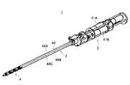
図1は、第1の実施形態の低侵襲外科手術用の鉗子1の外観を示す斜視図である。鉗子1は、ベース2と、ベース2から延びる軸部3と、軸部3の先端に設けられた作業部4とを備えている。(First embodiment)
FIG. 1 is a perspective view showing an appearance of a
低侵襲手術の際には、軸部3及び作業部4は患者の体内に挿入され、ベース2は患者の体外に配置される。ベース2において生じた駆動力が軸部3を介して作業部4に伝達され、作業部4が動作することにより、臓器の保持等の各種の作業が行われる。 In the case of minimally invasive surgery, the
具体的には、ベース2は、並列に配置された第1屈曲モータ41A、第2屈曲モータ41B、把持モータ41C(図1では、把持モータ41Cは第1屈曲モータ41A及び第2屈曲モータ41Bに隠れて不図示。把持モータ41Cは図8参照。以下、単に「モータ41」といい、これらを区別しないことがある。)と、これらモータ41の回転をそれぞれ適宜な減速比又は増速比で変速して伝達する不図示の伝達機構とを備えている。 Specifically, the
軸部3は、中空状軸部材43と、中空状軸部材43に挿通される3本の駆動軸44A、44B、44C(図1では点線で模式的に示す。以下、単に「駆動軸44」といい、これらを区別しないことがある)とを備えている。3本の駆動軸44A〜44Cは、それぞれ独立にモータ41A〜41Cによって回転駆動される。駆動軸44の回転が作業部4に伝達されることにより作業部4は動作する。 The
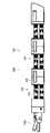
図2は、作業部4の外観を示す斜視図である。作業部4は、把持部6と、把持部6と軸部3とを連結するとともに、屈曲により把持部6を軸部3に対して任意の方向へ向ける屈曲部7とを備えている。屈曲部7は、3つの関節部9L、9M、9Nを連結して構成されている。なお、以下、単に「関節部9」といい、これらを区別しないことがある。 FIG. 2 is a perspective view showing an appearance of the working
図3(a)は、関節部9Mの外観斜視図であり、図3(b)は、関節部9Mの分解斜視図である。なお、後述するように、関節部9L及び9Nの主要な構成は関節部9Mと同様であるから、図3の説明において付加記号Mは省略する。 FIG. 3A is an external perspective view of the
関節部9は、ユニバーサルジョイント11A、11B、11Cを備えている。なお、以下では、単に、「ユニバーサルジョイント11」といい、これらを区別しないことがある。ユニバーサルジョイント11は、第1軸11aと第2軸11bとを備え、第1軸11aと第2軸11bとは、軸周りの任意の方向に、所定の角度範囲内で任意の角度を成し得るように連結されている。 The
関節部9は、ユニバーサルジョイント11A、11Bに対して同軸状に、第1ねじ12A、12B、スプライン中空部材13A、13B、第2ねじ14A、14Bを備えている。なお、以下では、ユニバーサルジョイント11A、11Bにそれぞれ対応することを示すA、Bの付加記号を省略することがある。 The
第1ねじ12は、ユニバーサルジョイント11の第2軸11bに形成された孔部に、雄ねじ部12aの先端が挿通されている。第1ねじ12の雄ねじ部12aの先端は回転不可能かつ軸方向に移動不可能に第2軸11bに対して固定されている。例えば、第2軸11bに圧入されることにより固定され、あるいは、接着剤や半田により固定されている。 As for the
スプライン中空部材13は概ね筒状に形成されており、孔部13aを有している。孔部13aは、第1ねじ12のボルト頭12b及び第2ねじ14のボルト頭14bと嵌合する形状である。換言すれば、スプライン中空部材13にはキー溝が形成されている。従って、第1ねじ12及び第2ねじ14は、ボルト頭12b、14bがスプライン中空部材13の孔部13aに挿通されることにより、互いに軸方向に近接及び離間可能、かつ、相対回転不可能に連結される。なお、ボルト頭12b、14b、孔部13aの断面形状は、例えば六角形である。 The spline
第2ねじ14は、隣接する他の関節部9のユニバーサルジョイント11の第1軸11aに形成された孔部に、雄ねじ部14aの先端が挿通されている。第2ねじ14の雄ねじ部14aの先端は回転不可能かつ軸方向に移動不可能に第1軸11aに対して固定されている。例えば、第1軸11aに圧入されることにより固定され、あるいは、接着剤や半田により固定されている。 As for the
なお、以下では、第2ねじ14、ユニバーサルジョイント11及び第1ねじ12を互いに固定した部材を、屈曲リンク21(図4参照)ということがある。 In the following, a member in which the
第1ねじ12と第2ねじ14とは、同一径、同一長さであり、また、雄ねじ部12aと雄ねじ部14aとは同一径、同一長さ、同一ピッチである。ただし、雄ねじ部12a、雄ねじ部14aの方向は逆方向である(例えば第1ねじ12が右ねじであれば第2ねじ12は左ねじ)。すなわち、第1ねじ12と第2ねじ14とは、雄ねじの切られる方向以外は同一である。 The
第1ねじ12の雄ねじ部12aには、ユニバーサルジョイント11の第2軸11bと第1ねじ12のボルト頭12bとの間において、第1プレート16の雌ねじ部16aが螺合している。換言すれば、第1ねじ12及び第1プレート16は、第1ねじ12の回転により第1プレート16を軸方向に送る送りねじ機構を構成している。 A female screw portion 16 a of the
また、第2ねじ14の雄ねじ部14aには、隣接する他のユニバーサルジョイント11の第1軸11aと第2ねじ14のボルト頭14bとの間において、第2プレート17の雌ねじ部17aが螺合している。換言すれば、第2ねじ14及び第2プレート17は、第2ねじ14の回転により第2プレート17を軸方向に送る送りねじ機構を構成している。 The female screw portion 14a of the
第1プレート16と第2プレート17との間には、第1プレート16と第2プレート17とを互いに固定する固定部材15が配置される。固定部材15は、例えば適宜な断面の柱状に形成されており、一方の端面に第1プレート16が、他方の端面に第2プレート17が当接し、第1プレート16及び第2プレート17に挿通された不図示のねじが固定部材15の端面に形成された雌ねじ部に螺合されることにより、第1プレート16及び第2プレート17を互いに固定する。 A fixing
なお、以下では、第1プレート16、第2プレート17、固定部材15を互いに固定した部材を、被連結部材23ということがある。 In the following, a member in which the
固定部材15は、スプライン中空部材13等が挿通される半円状の凹部を有している。また、第1プレート16及び第2プレート17の互いに対向する面には、スプライン中空部材13が挿通される軸受孔が雌ねじ部16a、17aと同心円状に形成されている。スプライン中空部材13は、固定部材15の凹部、第1プレート16及び第2プレート17の軸受孔により軸支されている。 The fixing
関節部9は、ユニバーサルジョイント11Cに対して同軸状に、固定軸18を備えている。固定軸18は、例えば、スプライン中空部材13と同径の大径部18aと、大径部18aから両側に延び、大径部18aよりも小径な第1小径部18b、第2小径部18cとを備えている。 The
第1小径部18bは、例えば第1ねじ12と同等の径であり、ワッシャー19に挿通されてから、ユニバーサルジョイント11Cの第2軸11bに形成された孔部に挿通され、回転不可能かつ軸方向に移動不可能に第2軸11bに対して固定されている。例えば、第2軸11bに圧入されることにより固定され、あるいは、接着剤や半田により固定されている。 The first
第2小径部18cは、例えば第2ねじ14と同等の径であり、不図示のワッシャーに挿通されてから、隣接する他の関節部9のユニバーサルジョイント11Cの第1軸11aに形成された孔部に挿通され、回転不可能かつ軸方向に移動不可能に第1軸11aに対して固定されている。例えば、第1軸11aに圧入されることにより固定され、あるいは、接着剤や半田により固定されている。 The second
なお、以下では、固定軸18の第2小径部18c、ユニバーサルジョイント11C及び固定軸18の第1小径部18bを互いに固定した部分を、把持リンク22(図4参照)ということがある。 Hereinafter, the portion where the second
第1プレート16の2つの雌ねじ部16aと、第1小径部18bを軸支する孔部とは、例えば正三角形を形成するように配置されている。第2プレート17の2つの雌ねじ部17a及び第2小径部18cを軸支する孔部も同様である。すなわち、2つの屈曲リンク21、把持リンク22は、均等な位置に配置されている。 The two female screw portions 16a of the
図2に示すように、関節部9Lは、図3に示した関節部9の構成要素を全て備えている。ただし、関節部9Lのユニバーサルジョイント11A及び11Bには、把持部6の把持プレート25に形成された雌ねじ部に螺合する第2ねじ14が挿通されて固定されている。また、関節部9Lのユニバーサルジョイント11Cには、把持プレート25に回転可能かつ軸方向に移動不可能に軸支された把持駆動軸26が挿通されて固定されている。 As shown in FIG. 2, the
関節部9Nは、図3に示した関節部9の構成要素のうち、ユニバーサルジョイント11と、第1ねじ12と、スプライン中空部材13(図2では不図示)と、第1プレート16とを備えている。第1プレート16は、中空状軸部材43の先端に設けられている。関節部9Nのユニバーサルジョイント11A及び11Bに対応する2つのスプライン中空部材13A、13Bは、それぞれ駆動軸44A、44B(図1参照)に対して固定されており、駆動軸44A、44Bの回転によりそれぞれ駆動される。関節部9Nのユニバーサルジョイント11Cには、関節部9Nの第1プレート16に軸支された軸部材46が挿通されて固定されている。軸部材46は、駆動軸44Cに対して固定されており、駆動軸44Cの回転により駆動される。 The
なお、図3においては、ユニバーサルジョイント11から、第1ねじ12、スプライン中空部材13を経由して、第2ねじ14までを1関節部として定義して説明した。しかし、図3では、図示の都合上、固定軸18の長さ相当を含むように1関節部を定義したに過ぎず、同一の部品の組が繰り返し連続する屈曲部7において、いずれの部品からいずれの部品までを1関節部として定義するかは適宜になし得る。例えば、第2ねじ14から、ユニバーサルジョイント11、第1ねじ12を経由して、スプライン中空部材13までを、換言すれば、屈曲リンク21からスプライン中空部材13までを1関節部として定義することもできる。本実施形態では、基本的に、図3に示した範囲を1関節部として説明するが、便宜的に、一の関節部9の第2ねじ14と、他の関節部9のユニバーサルジョイント11及び第1ねじ12とにより構成される屈曲リンク21を、前記他の関節部9(ユニバーサルジョイント11を含む関節部9)の屈曲リンク21として説明することがある。 In FIG. 3, the description has been made by defining from the universal joint 11 to the
図4は、関節部9の動作を説明する図であり、ユニバーサルジョイント11Aと11Bとが重なる方向に関節部9を見た側面図である。図4(a)は関節部9が真直ぐになる中立状態を、図4(b)は関節部9が最大屈曲角度σmaxまで曲がっている屈曲状態を示している。なお、図4では、ワッシャー19を省略して示している。FIG. 4 is a side view illustrating the operation of the
図4(a)に示すように、中立状態では、ユニバーサルジョイント11A〜11Cは真直ぐになっており、また、第1プレート16と第2プレート17とは平行である。第1ねじ12の第1プレート16に対する位置及び第2ねじ14の第2プレート17に対する位置は、ユニバーサルジョイント11A〜11Cの第1軸11aと第2軸11bとの交点を含む平面(直線Lcで示す)が、真直ぐな状態のユニバーサルジョイント11A〜11Cに直交するとともに、第1プレート16と第2プレート17との中間位置に位置するように、設定されている。 As shown in FIG. 4A, in the neutral state, the
図4(a)の中立状態から、ユニバーサルジョイント11A及び11Bを一方向へ回転させると、第1ねじ12と第2ねじ14とは雄ねじが互いに逆方向に形成されていることから、図4(b)に示すように、第1プレート16と第2プレート17とは、ユニバーサルジョイント11A及び11Bの位置において近接する。一方、ユニバーサルジョイント11Cの位置では、第1プレート16と第2プレート17とは、互いの近接及び離間が規制されている。従って、関節部9は、ユニバーサルジョイント11A及び11B側(図4の右側)へ屈曲することになる。 When the
この際、第1ねじ12と、第2ねじ14とは、同一ピッチで雄ねじが形成されており、屈曲リンク21の回転に対する送り量が同一であることから、屈曲に応じて直線Lcは屈曲角σを2分割するように移動する。すなわち、ユニバーサルジョイント11A〜11Cは、屈曲後も第1軸11a同士及び第2軸11b同士が互いに平行に保たれる。なお、第1ねじ12及び第2ねじ14の送り量が同一でない場合には、ユニバーサルジョイント11A〜11Cは、第1軸11a同士及び第2軸11b同士が互いに平行に保たれないことから、第1ねじ12及び第2ねじ14と、第1プレート16及び第2プレート17との嵌合ガタによって生じる傾斜量しか屈曲できない。 At this time, the
図示は省略するが、図4(a)の中立状態から、ユニバーサルジョイント11A及び11Bを他方向へ回転させた場合には、第1プレート16と第2プレート17とは、ユニバーサルジョイント11A及び11Bの位置において離間し、関節部9は図4(b)とは反対側へ屈曲する。また、ユニバーサルジョイント11Aの回転量と、ユニバーサルジョイント11Bの回転量とを互いに異ならせれば、関節部9はユニバーサルジョイント11A寄り、又は、ユニバーサルジョイント11B寄りに屈曲する。すなわち、関節部9は、ユニバーサルジョイント11周りの全方向へ屈曲可能である。 Although illustration is omitted, when the
関節部9の最大屈曲角度σmaxは、ユニバーサルジョイント11の最大屈曲角度により規定される。また、図4(b)においてユニバーサルジョイント11Aが第1プレート16や第2プレート17に当接し、第1ねじ12及び第2ねじ14の送りが規制されていることからも理解されるように、第1ねじ12及び第2ねじ14の第1プレート16や第2プレート17に対する可動範囲によっても規定される。従って、関節部9の最大屈曲角度σmaxを大きくするためには、第1ねじ12及び第2ねじ14の可動範囲を、ユニバーサルジョイント11の最大屈曲角度相当に設定しておくことが望ましい。なお、第1ねじ12及び第2ねじ14の可動範囲は、第1ねじ12の雄ねじ部12a及び第2ねじ14の雄ねじ部14aのユニバーサルジョイント11から突出する長さ、図4(a)に示す中立位置における第1ねじ12及び第2ねじ14の第1プレート16及び第2プレート17に対する螺合位置等により決定される。The maximum bending angle σmax of the
図5は、屈曲部7全体の動作を説明する図である。駆動軸44A(図5では不図示)の回転は、図2〜図4においても示したように、第1ねじ12A、ユニバーサルジョイント11A、第2ねじ14、スプライン中空部材13、再び第1ねじ12A、ユニバーサルジョイント11A、…の順で伝達されていくことにより、関節部9Nから関節部9Lまで順次伝達される。駆動軸44Bの回転も同様である。従って、関節部9L〜9Nは、互いに同一の方向へ同一の屈曲角度で屈曲する。そして、エンドエフェクタである把持部6は、軸部3に対して、関節部9L〜9Nの屈曲角度の総和に相当する角度だけ向きを変えつつ揺動する。 FIG. 5 is a diagram for explaining the operation of the entire
なお、屈曲部7全体の屈曲角度θは、以下のようになる。図4に示すように関節部9を見たとき、リンク間が最も離れている距離をx、第1ねじ12又は第2ねじ14の送り量をyとすると、各関節部9の屈曲角度σは、
σ=2tan-1(y/x) …(1)
となる。In addition, the bending angle θ of the
σ = 2 tan−1 (y / x) (1)
It becomes.
従って、屈曲部7全体の屈曲角度θは、屈曲部7の関節部9の数をNとすると、
θ=σ×N …(2)
となる。Accordingly, the bending angle θ of the
θ = σ × N (2)
It becomes.
一例として、3つの関節部9を有する屈曲部7において、最大屈曲角度θmax=90°とするためには、関節部9の最大屈曲角度σmax=30°である必要がある。図4の紙面上方側から見て、2つの屈曲リンク21及び把持リンク22を直径6mmの円状に120°刻みで配置した場合、2つの屈曲リンク21及び把持リンク22がなす正三角形の一辺の距離は5.2mm、頂点から対面の辺までの距離は4.5mmである。(1)式にσmax=30°、xmax=5.2mmを代入すると、ymaxは約1.4mmとなる。すなわち、第1ねじ12(第2ねじ14)が第1プレート16(第2プレート17)に対して1.4mm移動したとき、3つの関節部9からなる屈曲部7の最大屈曲角度θmaxは90°となる。As an example, in the bending
以下では、鉗子1の屈曲部7の任意の屈曲状態における屈曲角度θと屈曲方向φから、屈曲リンク21の回転量を求める逆運動学について述べる。 Hereinafter, the inverse kinematics for obtaining the amount of rotation of the bending
図6は、屈曲部7における座標系の定義を示している。把持部6の把持プレート25(図2も参照)には、関節部9Lの屈曲リンク21が螺合する雌ねじ部25a、25bが設けられるとともに、把持駆動軸26を軸支する軸受孔25cが設けられている。雌ねじ部25a、25b、軸受孔25cは例えば正三角形を成す。座標系の原点Oは把持プレート25の中央(雌ねじ部25a、25b、軸受孔25cの中央)とする。屈曲部7の屈曲方向φは、中立状態の屈曲部7の軸線方向に平行な軸Z1回りに、原点Oから軸受孔25c方向へ延びる軸X1の位置を基準として定義する。屈曲部7の屈曲角度θは、軸Z1から屈曲方向φへの傾斜角により定義する。 FIG. 6 shows the definition of the coordinate system in the
雌ねじ部25a、25bに螺合する第2ねじ14や各関節部9の第1ねじ12及び第1ねじ14のピッチをp、屈曲角度θのときの最大移動距離をyθmaxとすると、屈曲角度θのときの最大回転量δは、
δ=yθmax/p …(3)
となる。Assuming that the pitch of the
δ = y θmax / p ... ( 3)
It becomes.
(1)式及び(2)式より、最大移動距離をyθmaxは、
yθmax=xmaxtan(σ/2)=xmaxtan(θ/2/N) …(4)
となる。From equation (1) and equation (2), the maximum travel distance yθmax is
yθmax = xmax tan (σ / 2) = xmax tan (θ / 2 / N) (4)
It becomes.
2つの屈曲リンク21の回転量はそれぞれ、
α=δcos(φ−30°) …(5)
β=δcos(φ+30°) …(6)
となる。従って、屈曲角度θと屈曲方向φが決まれば、屈曲リンク21の回転量α、βが求まる。The amount of rotation of the two
α = δcos (φ-30 °) (5)
β = δcos (φ + 30 °) (6)
It becomes. Therefore, if the bending angle θ and the bending direction φ are determined, the rotation amounts α and β of the bending
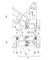
図7は、把持部6の構成を示す透視図であり、図7(a)は把持部6の閉状態を、図7(b)は把持部6の開状態を示している。 FIG. 7 is a perspective view showing the configuration of the
把持部6は、第1把持片28及び第2把持片29を備えている。第1把持片28及び第2把持片29は、軸部材30が挿通されることにより、軸部材30を回転軸として回動可能に連結されている。 The
第1把持片28及び第2把持片29は、スライダ・リンク機構により開閉方向に駆動される。具体的には、第1把持片28及び第2把持片29のうち、軸部材30よりも把持プレート25側の部分には、スリットがそれぞれ形成されている(第2把持片29のスリット29aのみ図示)。スリットは、把持プレート25側ほど内側(第1把持片28では図7の紙面下方側、第2把持片29では図7の紙面上方側)へ位置するように、第1把持片28、第2把持片29の長手方向に対してそれぞれ傾斜している。スリットには、リンク部材31に設けられた摺動軸31aが挿入されている。従って、リンク部材31が軸方向(図7の紙面左右方向)に移動することにより、摺動軸31aがスリット内を摺動し、第1把持片28及び第2把持片29は開閉する。 The
リンク部材31は、把持駆動軸26の回転運動が送りねじ機構により並進運動に変換されてリンク部材31に伝達されることにより駆動される。具体的には、リンク部材31に対して固定され、雌ねじ部が形成された雌ねじ部材32と、把持駆動軸26に対して同軸状に固定され、雌ねじ部材32に螺合する送りねじ33とにより、送りねじ機構が構成されている。 The
なお、把持駆動軸26は、駆動軸44C(図1参照)の回転が、軸部材46(図2参照)、ユニバーサルジョイント11C、固定軸18(図3参照)、再びユニバーサルジョイント11C、…の順で、関節部9Nから関節部9Lまで伝達されることにより、駆動される。 In the
図8は、鉗子1を含む手術システム51の信号処理系の構成を示すブロック図である。ただし、各種信号に付したαやβ等の記号は、信号の含む情報を概念的に説明するために付したものであり、各要素から入出力される信号を正確に示したものではない。 FIG. 8 is a block diagram showing the configuration of the signal processing system of the
手術システム51は、鉗子1の動作を制御するための操作装置52を備えている。操作装置52は鉗子1と電気的に接続されている。例えば、操作装置52は、基台を備え、その基台に鉗子1のベース2が固定されるなど、鉗子1と一体的に構成されて鉗子1と接続されている。あるいは、操作装置52は、操作装置52の一部又は全部が鉗子1とは離れた場所に設けられ、インターネット等のネットワークを介して鉗子1と接続されている。 The
操作装置52は、ユーザの操作を受け付ける操作部54、操作部54から出力される信号に基づいて鉗子1に制御信号を出力する制御部55、制御部55からの信号に基づいて所定の情報を表示する表示部56を備えている。 The operating
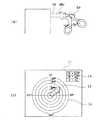
図9(a)は、操作部54の外観を示す側面図である。操作部54は、ジョイスティック58と、ジョイススティック58のレバー58aに設けられ、通常の(マニピュレータ鉗子でない)鉗子のレバー側の部分を模したコントローラ鉗子59とを備えている。なお、コントローラ鉗子59は、通常の鉗子をレバー58aに挿入することにより構成してよい。 FIG. 9A is a side view showing the appearance of the
ユーザは、レバー58aを倒す程度により屈曲部7の屈曲角度θを指定することができ、レバー58aを倒す方向により屈曲部7の屈曲方向φを指定することができ、コントローラ鉗子59の開閉度により把持部6の開閉度を指定することができる。 The user can specify the bending angle θ of the bending
すなわち、図8に示すように、操作部54は、レバー58aの傾斜角に応じた信号を屈曲角度θを指定する情報として、レバー58aの傾斜方向に応じた信号を屈曲方向φを指定する情報として、コントローラ鉗子59の開閉度に応じた信号を把持部6の開閉度(例えば軸心からの変位d)を指定する情報として、制御部55へ出力する。 That is, as shown in FIG. 8, the
制御部55は、例えばコンピュータにより構成されており、不図示のCPU、ROM、RAM、外部記憶装置等を含んで構成されている。制御部55は、(4)式、(3)式、(5)式及び(6)式に基づいて、操作部54からの信号から特定される屈曲角度θ及び屈曲方向φに対応する回転量α、βを算出する。また、変位dに対応する把持部6の送りねじ33の回転量γを送りねじ33のピッチ等に基づいて算出する。そして、回転量α、β、γを、あるいは、回転量α、β、γを伝達機構の増速比又は減速比等を考慮してモータ41A〜41Cの回転量に変換したものを第1屈曲駆動部61A、第2屈曲駆動部61B、把持駆動部61C(以下、単に「駆動部61」といい、これらを区別しないことがある)にそれぞれ出力する。 The
駆動部61は、入力された信号に応じた駆動電力をモータ41に出力する。また、モータ41に設けられた不図示のエンコーダにより検出される回転数に基づいて、モータ41の回転量が目標値に収束するようにフィードバック制御を行う。フィードバック制御は、例えば、PI制御である。 The
表示部56は、例えばCRTや液晶表示ディスプレイにより構成されている。制御部55は、算出したθ、φ、dに基づいて画像データを生成し、当該画像データを映像信号に変換して表示部56に出力する。表示部56は制御部55からの映像信号に基づく画像を表示する。 The
図9(b)は、表示部56の画面の一部又は全部に表示される画像I1の例を示している。画像I1にはベクトルI2が表示されている。ベクトルI2は、長さによって操作部54に入力された屈曲角度θを、指し示す方向によって操作部54に入力された屈曲方向φを示している。ベクトルI2の表示領域には、ベクトルI2の長さ及び方向を測るための目盛I3が表示されている。また、操作部54に入力されたθ、φ、dを数字で示すテーブルI4も画像I1に表示されている。 FIG. 9B shows an example of an image I1 displayed on a part or all of the screen of the
以上の第1の実施形態によれば、図4に示したように、把持リンク22が一の関節部9の被連結部材23と他の関節部9の被連結部材23との近接及び離間を規制する一方で、屈曲リンク21が一の関節部9の被連結部材23及び他の関節部9の被連結部材23にそれぞれ螺合して送りねじ機構を構成するとともに全方向に屈曲可能であることから、屈曲リンク21を回転させることにより、関節部9を屈曲させることができる。すなわち、関節部9に回転を入力して関節部9を屈曲又は湾曲させることができる。 According to the first embodiment described above, as shown in FIG. 4, the
屈曲リンク21の送りねじ機構は、ユニバーサルジョイント11の第1軸11a側及び第2軸11b側のそれぞれにおいて構成されるとともに、これら送りねじ機構は、屈曲リンク21の一方向への回転に対する送り方向が互いに逆方向、且つ、屈曲リンク21の回転に対する送り量が互いに同一であることから、図4において示したように、ユニバーサルジョイント11A〜11Cは、第1軸11a同士及び第2軸11b同士が互いに平行に保たれる。従って、屈曲リンク21の嵌合ガタを小さくしても屈曲可能であり、エンドエフェクタである把持部6の精密な位置制御が可能となる。 The feed screw mechanism of the bending
屈曲リンク21は、互いに異なる位置に2つ設けられていることから、2つの屈曲リンク21をそれぞれ独立に制御することにより、全方向への屈曲、すなわち、多自由度の屈曲が可能となる。多自由度の屈曲は、屈曲リンク21を3つ以上設けても可能であるが、2つとするのが最も部品点数を少なくすることができるとともに、制御も最も簡単である。また、従来のように、スライダ・リンク機構により多自由度の屈曲を実現した場合、一方向への屈曲と、当該一方向へ直交する方向への屈曲とは互いに異なる位置を支点として行われ、エンドエフェクタを球面状に移動させることができないが、本実施形態の関節部9では、一方向への屈曲も、当該一方向へ直交する方向への屈曲も同一位置(把持リンク22のユニバーサルジョイント11Cの第1軸11aと第2軸11bとの交点)を支点として行なわれるから、球面状にエンドエフェクタ等を移動させることが可能である。球面状にエンドエフェクタを移動させることができることから、例えば、屈曲部7を患者に挿入した状態で、屈曲部7の患者に対する姿勢を同一に保ちつつベース2を回転させることができる。 Since the two
関節部9を複数連結し、一の関節部9の屈曲リンク21と、他の関節部9の屈曲リンク21とを、近接及び離間可能に、且つ、相対回転不可能にスプライン中空部材13により連結していることから、連結した関節部9を同時に屈曲させ、屈曲部7全体における屈曲角度θを大きくすることができる。すなわち、エンドエフェクタである把持部6の位置や向きを大きく変化させることができる。 A plurality of
把持部6は、把持リンク22の回転により開閉駆動されることから、屈曲を実現するための把持リンク22を、把持部6の駆動機構の一部として兼用できる。すなわち、部材点数の削減、構成の簡素化が図られる。また、ワイヤーの張力により開閉する場合に比較して、把持に必要な剛性、耐久性を得ることが容易である。エンドエフェクタとしての把持部6に送りねじ機構を設けていることから、把持リンク22の回転をエンドエフェクタに入力して適宜な動作を行うことができる。 Since the
本実施形態の駆動軸44は回転駆動される。従来の低侵襲手術用のマニピュレータでは駆動軸は軸方向に直動されていた。直動される駆動軸と、回転駆動される駆動軸とは要求される強度が異なることから、駆動軸の材質や径の選定範囲が広がり、設計の自由度が向上する。また、例えば、モータ41等の回転を並進運動に変換して駆動軸44に伝達する機構を省略することができる。 The drive shaft 44 of this embodiment is rotationally driven. In a conventional manipulator for minimally invasive surgery, the drive shaft is linearly moved in the axial direction. Since the drive shaft that is linearly driven and the drive shaft that is rotationally driven have different required strengths, the selection range of the material and diameter of the drive shaft is expanded, and the degree of freedom in design is improved. Further, for example, a mechanism for converting rotation of the motor 41 or the like into translational motion and transmitting it to the drive shaft 44 can be omitted.
なお、第1の実施形態において、本発明の第1の観点の駆動機構に関し、屈曲部7を構成する機構は、駆動機構の一例であり、屈曲リンク21は、駆動用ユニバーサルジョイントの一例であり、把持リンク22は、規制用ユニバーサルジョイントの一例であり、屈曲リンク21及び把持リンク22の組合せは連結部の一例であり、第1ねじ12の雄ねじ部12a及び第2ねじ14の雄ねじ部14aは第1雄ねじ部及び第2雄ねじ部の一例である。 In the first embodiment, regarding the drive mechanism according to the first aspect of the present invention, the mechanism constituting the
第1の実施形態において、本発明の第2の観点の駆動機構に関し、屈曲部7を構成する機構は、駆動機構の一例であり、屈曲リンク21は、駆動用リンクの一例であり、把持リンク22は、規制用リンクの一例であり、把持リンク22と被連結部材23との連結位置は、第1位置及び第2位置の一例であり、屈曲リンク21と被連結部材23との連結位置は、第3位置及び第4位置の一例であり、第1ねじ12と第1プレート16とにより構成される送りねじ機構及び第2ねじ14と第2プレート17とにより構成される送りねじ機構は、第1接続部及び第2接続部に構成された送りねじ機構の一例であり、被連結部材23、屈曲リンク21、把持リンク22の組合せは関節部の一例であり、スプライン中空部材13は伝達部及びリンク連結部材の一例であり、把持部6の第1把持片28及び第2把持片29は、可動部材の一例である。 In the first embodiment, regarding the drive mechanism according to the second aspect of the present invention, the mechanism constituting the
第1の実施形態において、本発明の第3の観点の低侵襲外科手術用マニピュレータに関し、鉗子1は、低侵襲外科手術用マニピュレータの一例であり、把持部6の把持プレート25は、先端部材の一例である。 The first embodiment relates to a minimally invasive surgical manipulator according to the third aspect of the present invention. The
(第2の実施形態)
図10は、本発明の第2の実施形態の鉗子101の作業部104の外観を示す側面図である。作業部104は、第1の実施形態と同様に、把持部106と、屈曲部107とを備えており、屈曲部107は、3つの関節部109を連結して構成されている。関節部109を屈曲させる原理も第1の実施形態と同様である。すなわち、関節部109は、全方向に屈曲可能であるとともに送りねじとして機能し、被連結部材123同士を近接又は離間させる屈曲リンク121と、被連結部材123同士の近接又は離間を規制する規制リンク(不図示)とを備えている。(Second Embodiment)
FIG. 10 is a side view showing the appearance of the working
ただし、第2の実施形態では、屈曲リンク121の構成及び被連結部材123の構成の簡素化や部品点数の削減を図っている。なお、規制リンクの構成は第1の実施形態と同様としてよい。 However, in the second embodiment, the configuration of the
図11は、関節部109の一部分解斜視図である。なお、規制リンク等の一部の部材については図示を省略し、また、便宜的に他の関節部109の部材を一部示している。 FIG. 11 is a partially exploded perspective view of the joint 109. Note that illustration of some members such as the restriction link is omitted, and some members of other
屈曲リンク121は、いわば第1の実施形態の第2ねじ14、ユニバーサルジョイント11、第1ねじ12を一体化した構成となっている。すなわち、屈曲リンク121は第1軸121aと第2軸121bとを有し、第1軸121aと第2軸121bとは、全方向に屈曲可能に連結されてユニバーサルジョイントを構成しているとともに、第1軸121a及び第2軸121bにはそれぞれ、ねじ溝の方向が互いに逆方向でピッチが同一の第1雄ねじ部121c、第2雄ねじ部121dが形成されている。第1雄ねじ部121c及び第2雄ねじ部121dにはそれぞれ、軸方向に延びる第1スプライン溝121e、第2スプライン溝121fが3本ずつ形成されている。 In other words, the
被連結部材123は、第1プレート116と、第2プレート117とを有し、第1プレート116と、第2プレート117とは互いに当接して固定されている。すなわち、第1の実施形態の固定部材115は省略されている。第1プレート116には、他の関節部9の第2雄ねじ部121dに螺合する雌ねじ部116aが、第2プレート117には、第1雄ねじ部121cに螺合する雌ねじ部(不図示)が形成されている。すなわち、送りねじ機構が構成されている。 The
被連結部材123内部には、スプライン中空部材113が収納される。なお、紙面下方に示したのは、隣接する他の関節部9のスプライン中空部材113である。スプライン中空部材113は、第1雄ねじ部121c、第2雄ねじ部121dを挿通可能な筒状に形成されており、内周面には、第1スプライン溝121e、第2スプライン溝121fに嵌合する突条部113aが形成されている。従って、第1雄ねじ部121cと、隣接する他の関節部9の第2雄ねじ部121dとは、スプライン中空部材113によって、互いに近接及び離間可能に、かつ、相対回転不可能に連結される。 A spline
以上の第2の実施形態によれば、第1の実施形態と同様の効果が得られる。さらに、部品点数の削減等によりコスト低減が期待される。 According to the second embodiment described above, the same effect as in the first embodiment can be obtained. Furthermore, cost reduction is expected by reducing the number of parts.
(第3の実施形態)
図14は、本発明の第3の実施形態の鉗子301の外観を示す図であり、図14(a)は斜視図、図14(b)は側面図、図14(c)は図14(b)とは異なる方向から見た側面図である。鉗子301は、第1の実施形態や第2の実施形態と同様に、ベース302と、軸部303と、作業部304とを備えている。作業部304は、第1の実施形態や第2の実施形態と同様に、把持部306と、屈曲部307とを備えており、屈曲部307は、3つの関節部309を連結して構成されている。関節部309を屈曲させる原理も第1の実施形態や第2の実施形態と同様である。すなわち、関節部309は、全方向に屈曲可能であるとともに送りねじとして機能し、被連結部材323同士を近接又は離間させる屈曲リンク321と、被連結部材323同士の近接又は離間を規制する把持リンク322とを備えている。(Third embodiment)
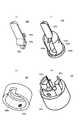
14A and 14B are views showing the appearance of the
ただし、第3の実施形態では、把持部306が回転軸RA周りに回転可能に構成されている点、把持部306の開閉動作がワイヤー331の張力によって行われる点が第1の実施形態や第2の実施形態と異なる。 However, in the third embodiment, the gripping
図15(a)は把持部306を開状態で示す斜視図、図15(b)は図15(a)のXVb−XVb線矢視方向における断面図である。 FIG. 15A is a perspective view showing the
把持部306は、把持片328と、把持片328を揺動可能に軸支する把持基部329と、把持基部329を回転軸RA周りに回転可能に保持する連結基体335及び支持基体325とを備えている。 The
図16(a)は把持片328を示す斜視図、図16(b)は把持基部329を示す斜視図、図16(c)は連結基体335を示す斜視図、図16(d)は支持基体325を示す斜視図である。 16 (a) is a perspective view showing the
把持片328及び把持基部329は、いわゆる片ばさみ構造により構成されており、把持片328は、揺動可能に把持基部329に保持されている。具体的には以下のとおりである。 The
図16(a)に示すように、把持片328は、全体として長尺状(例えば半円柱形状)に形成されている。把持片328の一端には軸支孔328aが形成されている。一方、図16(b)に示すように、把持基部329は、概略円筒状に形成された支持部329bと、支持部329bの先端に形成され、把持片328と同様に長尺状(例えば半円筒形状)に形成された把持突起329cとを備えている。支持部329bの側面には互いに対向する2つの支持孔329aが形成されている。 As shown in FIG. 16A, the
そして、図15(a)及び図15(b)に示すように、把持片328は軸支孔328a側の部分が支持部329bの内部に挿入され、軸支孔328a及び支持孔329aには支持軸330が挿通されている。支持軸330は、軸支孔328a及び支持孔329aの少なくとも一方に対して回転可能に軸支されている。従って、把持片328は把持基部329に対して支持軸330周りに揺動可能に軸支され、把持片328の揺動により、把持片328及び把持突起329cの開閉動作が行われる。 As shown in FIGS. 15A and 15B, the
把持基部329は、回転軸RA周りに回転可能に連結基体335及び支持基体325に保持される。具体的には、以下のとおりである。 The
図16(b)に示すように、把持基部329の支持部329bには、把持突起329cとは反対側の端部に外周側に突出するフランジ部329dが形成されている。フランジ部329dの外周縁は円形である。 As shown in FIG. 16B, a
一方、図16(d)に示すように、支持基体325は、先端側(図16(d)の紙面上方側)に縮径部325cを有しており、縮径部325cには、フランジ部329dを収容可能な凹部325aが形成されている。凹部325aの内周面は円形である。底面は例えば平面である。ただし、支持基体325には、屈曲リンク321や把持リンク322等が挿入される穴部が3つ形成されており、凹部325aの内周面は3つに分割されている。 On the other hand, as shown in FIG. 16D, the
また、図16(c)に示すように、連結基体335は、概ね円筒状に形成されている。連結基体335の内径は、支持基体325の縮径部325cの外径と同等である。連結基体335の一方の端面(図16(c)の紙面下方側)は開放されており、他方の端面には、フランジ部329dの外径よりも小さく、支持部329bの外径よりも大きい開口部335aが形成されている。 Further, as shown in FIG. 16C, the
そして、図15(a)及び図15(b)に示すように、把持基部329のフランジ部329dは支持基体325の凹部325aに挿入される。従って、把持基部329は回転軸RA周りに回転可能に支持基体325に支持される。なお、回転軸RAは、屈曲リンク321や把持リンク322の支持基体325への挿入方向と平行であり、また、2本の屈曲リンク321及び把持リンク322の中心に位置する。 Then, as shown in FIGS. 15A and 15B, the
把持基部329の把持突起329c及び支持部329bは、連結基体335の開口部335aに挿通され、把持基部329のフランジ部329dは、連結基体335の開口部335aの外周部分に係合する。また、支持基体325の縮径部325cは連結基体335に嵌合挿入される。従って、把持基部329の凹部325aからの抜け止めがなされる。 The
連結基体335と支持基体325との固定は、例えば、ねじ等の固定を解除可能な連結部材により行う。例えば、連結基体335のうち、支持基体325の縮径部325cを覆う側面に雌ねじ部335b(図16(c)参照)を、縮径部325cの側面に雌ねじ部335bと略同径の穴部325b(図16(d)参照)を形成し、雄ねじ339を雌ねじ部335bに螺合しつつ穴部325bに挿通することにより、連結基体335と支持基体325とを固定する。 The
把持基部329は、把持リンク322の回転により回転駆動される。具体的には以下のとおりである。 The
図15(a)及び図15(b)に示すように、支持基体325には、第1の実施形態の把持プレート25と同様に、被連結部材を近接又は離間させるための屈曲リンク321が螺合され、また、被連結部材の近接又は離間を規制するための把持リンク322が回転可能に且つ軸方向に移動不可能に軸支されている。 As shown in FIGS. 15A and 15B, the
図15(b)に示すように、把持リンク322の支持基体325に挿入されている軸部には、ギア336が固定されている。また、把持基部329の穴部には、ギア336に噛合するギア337が挿入及び固定されている。従って、把持リンク322の回転は、ギア336及びギア337からなる歯車装置(歯車列)により把持基部329に伝達され、把持基部329は回転軸RA周りに回転する。なお、把持リンク322は、第1の実施形態と同様に、ベース302に設けられたモータの回転が伝達されて回転する。 As shown in FIG. 15B, a
把持片328は、ワイヤー331の張力によって駆動される。具体的には以下のとおりである。 The
図16(a)に示すように、把持片328の軸支孔328a側の端部には、把持片328の長手方向に対して若干把持突起329c側(図16(a)の紙面下方側)に突出する閉動作用突起328bと、把持片328の長手方向に対して把持突起329cとは反対側に突出する開動作用突起328cとが設けられている。閉動作用突起328b及び開動作用突起328cには、例えば、ワイヤー331を固定し易いように、ワイヤー331を挿通可能な孔部が設けられている。 As shown in FIG. 16 (a), at the end of the
図14(b)及び図14(c)に示すように、ワイヤー331は、一端がベース302に設けられた閉動作用モータ332の出力軸に固定され、閉動作用突起328b及び開動作用突起328c(図16(a))を経由して、他端がベース302に設けられた開動作用モータ333の出力軸に固定されている。 As shown in FIGS. 14B and 14C, one end of the
具体的には、ワイヤー331は、閉動作用モータ332の出力軸から、滑車などに案内されつつ、軸部303の内部へ挿通され、軸部303の内部を通って屈曲部307に到達し、屈曲部307では、被連結部材323の中心に設けられた孔部などに案内されて把持部306に到達している。把持部306内では、ワイヤー331は、図15(b)に示すように、支持基体325に設けられた不図示の穴部やギア337の中心穴を通って把持片328に到達する。そして、把持片328の閉動作用突起328bに固定された後、開動作用突起328cにも固定される。その後、ワイヤー331は、往路と同様に、屈曲部307、軸部303を経由して開動作用モータ333の出力軸に固定されている。 Specifically, the
従って、閉動作用モータ332の駆動によりワイヤー331が巻き取られると、ワイヤー331の張力により閉動作用突起328bが引っ張られ、把持片328は軸支孔328aを中心として閉方向へ回転する。逆に、開動作用モータ333の駆動によりワイヤー331が巻き取られると、ワイヤー331の張力により開動作用突起328cが引っ張られ、把持片328は軸支孔328aを中心として開方向へ回転する。 Therefore, when the
以上の実施形態によれば、第1の実施形態及び第2の実施形態と同様の効果が得られる。さらに、把持リンク322の回転により把持部306を回転させることから、把持部306の姿勢変更が容易になるとともに、把持リンク322の有効利用が図られる。 According to the above embodiment, the same effect as the first embodiment and the second embodiment can be obtained. Furthermore, since the
把持部306の開閉をワイヤー331によって行っていることから、開閉動作の応答性を向上させることができる。また、連結基体335と支持基体325とを分離することにより把持片328を含む先端部だけを取り外すことができることから、ワイヤー331の交換等が容易である。
なお、第3の実施形態において、把持基部329は、本発明の開閉動作可能な部材(一例として把持片328)と共に第2被連結部材に対して回転可能な可動部材の一例である。Since the holding
In the third embodiment, the
本発明は、以上の実施形態に限定されず、種々の態様で実施してよい。 The present invention is not limited to the above embodiment, and may be implemented in various aspects.
本発明の駆動機構が適用される技術分野は、低侵襲手術用のマニピュレータに限定されず、あらゆる技術分野に亘る。例えば、建築土木工事において地面を掘りおこして土砂を運搬するのに用いられるパワーショベル等、土木建築用機械に適用されてもよいし、人間の手を模したマジックハンドの指、象のロボットの鼻等、玩具に用いられてもよい。また、マニピュレータに適用される場合には、低侵襲手術用のものに限定されず、原子炉に対する各種の作業や人工衛星における作業を行うマニピュレータなど、各種の分野のマニピュレータに適用されてよい。低侵襲手術用のマニピュレータに適用される場合には、その適用対象は鉗子に限定されず、例えば剪刀、ナイフ、キュレット、持針器に適用されてもよい。 The technical field to which the drive mechanism of the present invention is applied is not limited to a manipulator for minimally invasive surgery, but covers all technical fields. For example, it may be applied to civil engineering and construction machines such as excavators used to dig the ground and carry earth and sand in construction and civil engineering work. Etc., and may be used for toys. Further, when applied to a manipulator, it is not limited to those for minimally invasive surgery, and may be applied to manipulators in various fields such as manipulators for performing various operations on nuclear reactors and operations on artificial satellites. When applied to a manipulator for minimally invasive surgery, the application target is not limited to forceps, and may be applied to, for example, a scissors, a knife, a curette, or a needle holder.
本発明の駆動機構は、第1被連結部材と第2被連結部材とが相対運動をすればよく、エンドエフェクタを適宜な位置、向きにするものに限定されない。上述のマジックハンドの指や象のロボットの鼻のように、駆動機構自体が最終的な制御対象であってもよい。 The drive mechanism of the present invention is not limited to a mechanism in which the first connected member and the second connected member are allowed to move relative to each other, and the end effector is set to an appropriate position and orientation. The drive mechanism itself may be the final control target, such as the above-mentioned magic hand finger or elephant robot nose.
駆動用リンクの本数は適宜に設定してよく、2本に限定されない。2本の屈曲リンク21が重なる方向の図である図4からも理解されるように、1自由度の屈曲を得るだけであれば、駆動用リンクは1本でもよい。また、多自由度の屈曲を得るために3本以上の駆動用リンクを設けてもよい。 The number of drive links may be set as appropriate and is not limited to two. As can be understood from FIG. 4, which is a view in a direction in which two
送りねじ機構は駆動用リンクの両端のうち、一方のみに設けられていてもよい。 The feed screw mechanism may be provided on only one of the ends of the drive link.
図12(a)は、駆動用リンクの両端のうち、一方のみに送りねじ機構を設けた変形例を示している。この変形例では、駆動用リンク201の第1軸201a及び第2軸201bのうち、第1軸201aのみに送りねじ機構が設けられている。この変形例においても、駆動用リンク201を回転させて、被連結部材203及び204を近接又は離間させる一方で、規制用リンク202により被連結部材203及び204の近接及び離間を規制することにより、屈曲動作を実現できる。 FIG. 12A shows a modified example in which a feed screw mechanism is provided on only one of both ends of the drive link. In this modification, a feed screw mechanism is provided only on the
ただし、図12(a)の変形例では、例えば、規制用リンク202をユニバーサルジョイントにより構成すると、駆動用リンクと規制用リンクとを平行に保つことができないことから(図4参照)、ガタ等に相当する傾きしか屈曲させることができない。そこで、規制用リンク202は、例えば、蛇腹管等の屈曲点が複数ある部材、換言すれば、適宜な形状に湾曲できる部材により構成する。図12(a)の変形例は、例えば、象のロボット玩具の鼻など、精密な制御を必要としない技術分野において利用できる。 However, in the modified example of FIG. 12A, for example, if the
規制用リンクは、駆動用リンクと同一の構成であってもよい。換言すれば、規制用リンクを設けない一方で、駆動用リンクを複数設け、1の駆動用リンクを他の駆動用リンクに対して規制用リンクとして機能させるようにしてもよい。 The restriction link may have the same configuration as the drive link. In other words, while providing no restriction link, a plurality of drive links may be provided, and one drive link may function as a restriction link with respect to other drive links.
図12(b)は、規制用リンクを、駆動用リンクと同一の構成とした変形例を示している。この変形例では、2つの駆動用リンク206により1自由度の屈曲機構が構成されている。一方の駆動用リンク206を規制用リンクとして機能させることにより、すなわち、一方の駆動用リンク206の回転を規制することにより、屈曲動作が行われる。 FIG. 12B shows a modification in which the restriction link has the same configuration as the drive link. In this modification, a bending mechanism having one degree of freedom is constituted by the two
さらに、この変形例では、一方の駆動用リンク206を、被連結部材207、208を近接させる方向に、他方の駆動用リンク206を、被連結部材207、208を離間させる方向に回転させれば、2倍の速度で屈曲動作を行うことができるとともに、駆動用リンク206、207の中央を屈曲点とすることができる。また、双方の駆動用リンク206を、被連結部材207、208を近接させる方向に、又は、双方の駆動用リンクを、被連結部材207、208を離間させる方向に回転させれば、屈曲させずに被連結部材207、208間の距離を変化させることができる。なお、駆動用リンクを3つ以上設けて多自由度の屈曲機構とした場合も同様である。 Furthermore, in this modified example, if one
一の関節部の駆動用リンクの回転を他の関節部の駆動用リンクに伝達する伝達部は、駆動用リンク同士を同一方向へ回転させるものに限定されない。例えば、駆動用リンク間にディファレンシャルギアを設け、一の関節部の駆動用リンクの回転を逆方向の回転に変換して他の関節部の駆動用リンクに伝達してもよい。 The transmission unit that transmits the rotation of the drive link of one joint part to the drive link of the other joint part is not limited to one that rotates the drive links in the same direction. For example, a differential gear may be provided between the driving links, and the rotation of the driving link of one joint portion may be converted into the rotation in the reverse direction and transmitted to the driving link of the other joint portion.
複数の関節部を連結する場合、駆動用リンクは、互いに独立に回転可能であってもよい。 When connecting a plurality of joint portions, the drive links may be rotatable independently of each other.
図13(a)は、2つの関節部211の駆動用リンク212を互いに独立に回転可能とした変形例を示している。各関節部211の被連結部材213には、駆動用リンク212を回転駆動するモータ214がそれぞれ設けられている。各モータ214は、駆動用リンク212等により案内されるケーブル等を介して駆動電力が供給され、それぞれ独立に制御される。図13(a)の変形例では、複数の被連結部材213を互いに異なる方向へ向けるなど、複雑な動作が可能となる。 FIG. 13A shows a modification in which the driving
可動部材(実施形態の把持片など)は、規制用リンクの回転によって駆動されるものに限定されない。 The movable member (such as the grip piece in the embodiment) is not limited to one driven by the rotation of the restriction link.
図13(b)は、規制用リンク216に案内されるワイヤー217の張力によって把持片218が被連結部材220に対して回転軸221回りに回転駆動され、把持片218及び把持片219の閉動作が行われる変形例を示している。なお、把持片218及び把持片219の開動作はバネ等の不図示の付勢手段により行われる。規制用リンク216は、例えば、筒状の第1軸216a及び第2軸216bを含んで構成されており、ワイヤー217は、規制用リンク216に挿通されて案内されており、規制用リンク216の屈曲に応じて屈曲する。この変形例では、規制用リンク216がワイヤー217を案内する案内部材として兼用されており、部品点数の削減が図られる。なお、規制用リンク216によるワイヤー217の案内は、規制用リンク216の内部においてワイヤー217を案内するものに限定されず、規制用リンク216の外部にワイヤー217が挿通されるリングを形成するなどして、規制用リンク216の外部においてワイヤー217を案内するものでもよい。 FIG. 13B shows the closing operation of the
可動部材が規制用リンクの回転によって駆動されるものである場合、可動部材は、開閉動作を行うものや第2被連結部材に対して回転動作を行うものに限定されない。例えば、単に第2被連結部材に揺動するもの、第2被連結部材に対して規制用リンクの軸方向に進退動作するものであってもよい。 When the movable member is driven by the rotation of the restriction link, the movable member is not limited to one that performs an opening / closing operation or one that performs a rotation operation on the second connected member. For example, it may simply swing on the second connected member, or move forward and backward in the axial direction of the regulating link relative to the second connected member.
可動部材が規制用リンクの回転によって開閉駆動されるものである場合、可動部材は、他の部材と開閉動作可能に他の部材に対して所定の回転軸周りに揺動可能に連結されるものであればよい。従って、第1の実施形態のように両開きになるものであってもよいし、第3の実施形態のように片開きになるものであってもよい。また、可動部材は、駆動用リンクや規制用リンクの伸長方向の先端側を開閉するもの、換言すれば、揺動の回転軸が駆動用リンクや規制用リンクに直交するものに限定されない。例えば揺動の回転軸が駆動用リンクや規制用リンクの伸長方向に沿っていてもよい。可動部材は把持部を構成するものに限定されず、例えば剪刀であってもよい。 In the case where the movable member is driven to open and close by the rotation of the restriction link, the movable member is connected to the other member so as to be able to open and close with respect to the other member so as to be swingable around a predetermined rotation axis. If it is. Therefore, it may be a double opening as in the first embodiment, or a single opening as in the third embodiment. Further, the movable member is not limited to a member that opens and closes the distal end side in the extending direction of the driving link or the regulating link, in other words, a swinging rotation axis that is orthogonal to the driving link or the regulating link. For example, the swinging rotation axis may be along the extending direction of the drive link or the regulation link. A movable member is not limited to what comprises a holding part, For example, a scissors may be sufficient.
可動部材が規制用リンクの回転によって回転駆動されるものである場合、可動部材は、開閉動作可能な部材を保持して当該部材の姿勢を変更するものに限定されない。例えば、可動部材は、当該可動部材自体がエンドエフェクタである、ドリル等の部材であってもよい。また、可動部材が他の部材を保持して当該他の部材の姿勢を変更するものである場合、他の部材は、開閉動作可能な部材に限定されず、例えば単に揺動する部材や進退動作する部材であってもよい。可動部材が開閉動作可能な部材を保持して当該部材の姿勢を変更するものである場合、開閉動作可能な部材は、上述のように、開閉方向の向きや種類(用途)は適宜に選択可能である。 When the movable member is rotationally driven by the rotation of the restriction link, the movable member is not limited to a member that holds a member that can be opened and closed and changes the posture of the member. For example, the movable member may be a member such as a drill whose movable member itself is an end effector. When the movable member holds another member and changes the posture of the other member, the other member is not limited to a member that can be opened and closed. It may be a member. When the movable member holds a member that can be opened and closed and changes the posture of the member, the direction and type (use) of the opening and closing direction can be appropriately selected as described above. It is.
駆動用リンクは、全方向へ屈曲又は湾曲することができればよく、ユニバーサルジョイントを含んで構成されるものに限定されない。すなわち、駆動用リンクは、軸方向の剛性が比較的高く、曲げ剛性が比較的低ければ、被連結部材と被連結部材とを近接又は離間させるとともに、被連結部材と被連結部材との相対角度の変化に応じて屈曲又は湾曲し、屈曲動作を実現できる。従って、駆動用リンクは、例えば、ユニバーサルジョイントに代えてボールジョイントを含んで構成されてもよい。図12(a)において規制用リンクとして例示したような蛇腹管を含んで構成されてもよい。比較的硬質のゴムを含んで構成されてもよい。 The drive link only needs to be able to bend or bend in all directions, and is not limited to a structure including a universal joint. That is, if the drive link has a relatively high axial rigidity and a relatively low bending rigidity, the connected member and the connected member are brought close to or separated from each other, and the relative angle between the connected member and the connected member It bends or curves in accordance with the change in the angle, and a bending operation can be realized. Therefore, the drive link may be configured to include a ball joint instead of the universal joint, for example. You may comprise including the bellows pipe which was illustrated as a link for control in Drawing 12 (a). A relatively hard rubber may be included.
規制用リンクは、駆動用リンクによる連結位置とは異なる位置において、第1被連結部材と第2被連結部材との近接及び離間を規制できればよく、回転できなくてもよいし、屈曲できなくてもよい。例えば、一の軸状部材により規制用リンクを形成し、その両端に球体を設けて、当該球体を第1被連結部材及び第2被連結部材により、ボールジョイントのように支持してもよい。 The restriction link only needs to be able to restrict the proximity and separation between the first connected member and the second connected member at a position different from the connection position by the drive link, and may not be able to rotate or bend. Also good. For example, the restriction link may be formed by one shaft-shaped member, and spheres may be provided at both ends thereof, and the sphere may be supported like a ball joint by the first connected member and the second connected member.
送りねじ機構は、駆動用リンクに雄ねじ部が、被連結部材に雌ねじ部が形成されるものに限定されず、駆動用リンクに雌ねじ部が、被連結部材に雄ねじ部が形成されてもよい。 The feed screw mechanism is not limited to the one in which the male screw portion is formed in the driving link and the female screw portion is formed in the connected member, and the female screw portion may be formed in the driving link and the male screw portion may be formed in the connected member.
1…鉗子、11a…第1軸(軸部)、11b…第2軸(軸部)、12a…雄ねじ部(第1雄ねじ部又は第2雄ねじ部)、14a…雄ねじ部(第1雄ねじ部又は第2雄ねじ部)、21…屈曲リンク(駆動用ユニバーサルジョイント、駆動用リンク)、22…把持リンク(規制用ユニバーサルジョイント、規制用リンク)、23…被連結部材。
DESCRIPTION OF
Claims (13)
Translated fromJapanese前記連結部は、前記第1被連結部材及び前記第2被連結部材を連結する規制用ユニバーサルジョイント及び駆動用ユニバーサルジョイントを備え、
前記規制用ユニバーサルジョイントは、前記第1被連結部材及び前記第2被連結部材に対して軸方向に移動不可能に連結され、
前記駆動用ユニバーサルジョイントの一方の軸部には、前記第1被連結部材に形成された第1雌ねじ部に螺合する第1雄ねじ部が形成され、
前記駆動用ユニバーサルジョイントの他方の軸部には、前記第2被連結部材に形成された第2雌ねじ部に螺合する第2雄ねじ部が形成され、
前記第1雄ねじ部及び前記第2雄ねじ部は、前記駆動用ユニバーサルジョイントを一方向へ回転させたときに前記第1被連結部材及び前記第2被連結部材を近接させ、他方向へ回転させたときに前記第1被連結部材及び前記第2被連結部材を離間させるように互いに逆方向に形成されるとともに、互いに同一ピッチに形成されている
駆動機構。A drive mechanism that bends a connecting portion that connects the first connected member and the second connected member,
The connecting portion includes a regulating universal joint and a driving universal joint for connecting the first connected member and the second connected member,
The regulating universal joint is connected to the first connected member and the second connected member so as not to move in the axial direction,
A first male screw portion that is screwed into a first female screw portion formed in the first connected member is formed on one shaft portion of the driving universal joint,
A second male screw portion that is screwed into a second female screw portion formed on the second connected member is formed on the other shaft portion of the universal joint for driving,
The first male screw portion and the second male screw portion are rotated in the other direction by causing the first connected member and the second connected member to approach each other when the driving universal joint is rotated in one direction. Sometimes the first connected member and the second connected member are formed in opposite directions so as to be separated from each other, and are formed at the same pitch.
第2被連結部材と、
前記第1被連結部材の第1位置と前記第2被連結部材の第2位置とを近接及び離間を規制可能に連結する規制用リンクと、
前記第1被連結部材の前記第1位置とは異なる第3位置と前記第2被連結部材の前記第2位置とは異なる第4位置とを連結する駆動用リンクと、
を備え、
前記駆動用リンクと前記第1被連結部材との第1接続部及び前記駆動用リンクと前記第2被連結部材との第2接続部のうち少なくとも一方には、前記駆動用リンクを一方向へ回転させたときに前記第1被連結部材及び前記第2被連結部材を近接させ、他方向へ回転させたときに前記第1被連結部材及び前記第2被連結部材を離間させるように、送りねじ機構が構成され、
前記駆動用リンクは回転軸周りの全方向へ屈曲又は湾曲可能である
駆動機構。A first connected member;
A second connected member;
A regulating link that couples the first position of the first coupled member and the second position of the second coupled member so as to regulate proximity and separation; and
A drive link for connecting a third position different from the first position of the first connected member and a fourth position different from the second position of the second connected member;
With
At least one of the first connection portion between the drive link and the first connected member and the second connection portion between the drive link and the second connected member is provided with the drive link in one direction. The first connected member and the second connected member are brought close to each other when rotated, and the first connected member and the second connected member are separated when rotated in the other direction. The screw mechanism is configured,
The drive link is capable of bending or bending in all directions around a rotation axis.
前記第1接続部の送りねじ機構及び前記第2接続部の送りねじ機構は、前記駆動用リンクの一方向への回転に対する送り方向が互いに逆方向、且つ、前記駆動用リンクの回転に対する送り量が互いに同一である
請求項2に記載の駆動機構。The feed screw mechanism is configured in each of the first connection portion and the second connection portion,
In the feed screw mechanism of the first connection part and the feed screw mechanism of the second connection part, the feed directions with respect to the rotation of the drive link in one direction are opposite to each other, and the feed amount with respect to the rotation of the drive link The drive mechanism according to claim 2, wherein are identical to each other.
請求項2に記載の駆動機構。The drive mechanism according to claim 2, wherein two drive links are provided at different positions.
請求項2に記載の駆動機構。The drive mechanism according to claim 2, wherein the restriction link has the same configuration as the drive link.
前記一の関節部の前記駆動用リンクの回転を前記隣接する他の関節部の前記駆動用リンクに伝達する伝達部と、
を備えた請求項2に記載の駆動機構。One joint part is configured including the first connected member, the regulating link, and the driving link, and the first connected member of one joint part is the first of the other joint parts adjacent to each other. A plurality of joints connected to function as two connected members;
A transmission unit for transmitting rotation of the driving link of the one joint part to the driving link of the other adjacent joint part;
The drive mechanism according to claim 2, comprising:
請求項6に記載の駆動機構。The transmission part is a link connecting member that connects the driving link of the one joint part and the driving link of the other adjacent joint part so as to be close to and away from each other and not to be relatively rotatable. The drive mechanism according to claim 6.
前記複数の関節部の駆動用リンクを互いに独立に回転駆動する複数の駆動源と、
を備えた請求項2に記載の駆動機構。One joint part is configured including the first connected member, the regulating link, and the driving link, and the first connected member of one joint part is the first of the other joint parts adjacent to each other. A plurality of joints connected to function as two connected members;
A plurality of drive sources for rotationally driving the drive links of the plurality of joints independently of each other;
The drive mechanism according to claim 2, comprising:
前記規制用リンクは、前記第1被連結部材及び前記第2被連結部材に回転可能に軸支され、且つ、回転軸周りの全方向へ屈曲又は湾曲可能であり、
前記可動部材は、前記規制用リンクの回転により駆動される
請求項2に記載の駆動機構。The second connected member is provided with a movable member movable with respect to the second connected member,
The restriction link is rotatably supported by the first connected member and the second connected member, and can be bent or curved in all directions around the rotation axis.
The drive mechanism according to claim 2, wherein the movable member is driven by rotation of the restriction link.
請求項9に記載の駆動機構。The movable member is connected to another member so as to be able to open and close with respect to the other member so as to be swingable around a predetermined rotation axis, and is opened and closed by rotation of the restriction link. 9. The drive mechanism according to 9.
請求項9に記載の駆動機構。The drive according to claim 9, wherein the movable member holds a member that can be opened and closed, and is rotationally driven with respect to the second connected member together with the member that can be opened and closed by rotation of the restriction link. mechanism.
前記可動部材は、前記規制用リンクに案内されたワイヤーの張力により駆動される
請求項2に記載の駆動機構。The second connected member is provided with a movable member movable with respect to the second connected member,
The drive mechanism according to claim 2, wherein the movable member is driven by a tension of a wire guided by the restriction link.
患者の外部から内部へ挿通される中空状軸部材と、
前記中空状軸部材の先端に設けられる先端部材と、
前記中空状軸部材の第1位置と前記先端部材の第2位置とを近接及び離間を規制可能に連結する規制用リンクと、
前記中空状軸部材の前記第1位置とは異なる第3位置と前記先端部材の前記第2位置とは異なる第4位置とを連結する駆動用リンクと、
前記中空状軸部材に回転可能に挿通され、前記駆動用リンクを回転可能に前記駆動用リンクに連結される駆動軸と、
を備え、
前記駆動用リンクと前記第1被連結部材との第1接続部及び前記駆動用リンクと前記第2被連結部材との第2接続部のうち少なくとも一方には、前記駆動用リンクを一方向へ回転させたときに前記第1被連結部材及び前記第2被連結部材を近接させ、他方向へ回転させたときに前記第1被連結部材及び前記第2被連結部材を離間させるように、送りねじ機構が構成され、
前記駆動用リンクは回転軸周りの全方向へ屈曲又は湾曲可能である
低侵襲外科手術用マニピュレータ。
A minimally invasive surgical manipulator comprising:
A hollow shaft member inserted from the outside to the inside of the patient;
A tip member provided at the tip of the hollow shaft member;
A restricting link for connecting the first position of the hollow shaft member and the second position of the tip member so as to be able to restrict proximity and separation;
A drive link connecting a third position different from the first position of the hollow shaft member and a fourth position different from the second position of the tip member;
A drive shaft rotatably inserted into the hollow shaft member and coupled to the drive link to rotate the drive link;
With
At least one of the first connection portion between the drive link and the first connected member and the second connection portion between the drive link and the second connected member is provided with the drive link in one direction. The first connected member and the second connected member are brought close to each other when rotated, and the first connected member and the second connected member are separated when rotated in the other direction. The screw mechanism is configured,
The manipulator for minimally invasive surgical operation, wherein the drive link can be bent or bent in all directions around a rotation axis.
Priority Applications (1)
| Application Number | Priority Date | Filing Date | Title |
|---|---|---|---|
| JP2006212396AJP4984280B2 (en) | 2006-03-27 | 2006-08-03 | Drive mechanism |
Applications Claiming Priority (3)
| Application Number | Priority Date | Filing Date | Title |
|---|---|---|---|
| JP2006085324 | 2006-03-27 | ||
| JP2006085324 | 2006-03-27 | ||
| JP2006212396AJP4984280B2 (en) | 2006-03-27 | 2006-08-03 | Drive mechanism |
Publications (2)
| Publication Number | Publication Date |
|---|---|
| JP2007292276Atrue JP2007292276A (en) | 2007-11-08 |
| JP4984280B2 JP4984280B2 (en) | 2012-07-25 |
Family
ID=38763074
Family Applications (1)
| Application Number | Title | Priority Date | Filing Date |
|---|---|---|---|
| JP2006212396AExpired - Fee RelatedJP4984280B2 (en) | 2006-03-27 | 2006-08-03 | Drive mechanism |
Country Status (1)
| Country | Link |
|---|---|
| JP (1) | JP4984280B2 (en) |
Cited By (7)
| Publication number | Priority date | Publication date | Assignee | Title |
|---|---|---|---|---|
| JP2016036426A (en)* | 2014-08-06 | 2016-03-22 | パナソニックIpマネジメント株式会社 | Suction tool and vacuum cleaner using the same |
| JP2016154717A (en)* | 2015-02-25 | 2016-09-01 | 日本トムソン株式会社 | Forceps of articulated structure |
| JP2017038776A (en)* | 2015-08-19 | 2017-02-23 | 日本トムソン株式会社 | Forceps having multi-joint structure |
| US9796092B2 (en) | 2015-01-21 | 2017-10-24 | Nippon Thompson Co., Ltd. | Multi-articulated manipulator |
| JP2018008335A (en)* | 2016-07-13 | 2018-01-18 | キヤノン株式会社 | Continuum robot, method of correcting kinematics of the same, and control method of continuum robot |
| JP2018094290A (en)* | 2016-12-16 | 2018-06-21 | 上銀科技股▲分▼有限公司 | Clamp device |
| CN113319887A (en)* | 2021-06-15 | 2021-08-31 | 郑州科技学院 | Adjustable numerical control mechanical arm joint |
Citations (12)
| Publication number | Priority date | Publication date | Assignee | Title |
|---|---|---|---|---|
| JPS609676A (en)* | 1983-06-30 | 1985-01-18 | 株式会社東芝 | Manipulator structure |
| JPS6048293A (en)* | 1983-08-29 | 1985-03-15 | 川崎重工業株式会社 | industrial robot arm |
| JPS60108291A (en)* | 1983-11-16 | 1985-06-13 | 日本精工株式会社 | Joint section structure |
| JPS61236493A (en)* | 1985-04-12 | 1986-10-21 | 三菱重工業株式会社 | Multi-joint robot arm |
| JPS61243399A (en)* | 1985-04-18 | 1986-10-29 | ドイツチエ・ゲゼルシヤフト・フユ−ル・ヴイ−ダ−アウフアルバイツンク・フオン・ケルンブレンシユトツフエン・ミツト・ベシユレンクテル・ハフツング | Remote controllable supporter combining positioning for remote treater |
| JPS62193790A (en)* | 1986-02-19 | 1987-08-25 | 三菱重工業株式会社 | Flexible robot arm |
| JPH0253389U (en)* | 1988-10-13 | 1990-04-17 | ||
| JPH0833644A (en)* | 1994-03-17 | 1996-02-06 | Terumo Corp | Appliance for surgery |
| JP2002113681A (en)* | 2000-08-04 | 2002-04-16 | Thk Co Ltd | Robot joint structure |
| JP2004154877A (en)* | 2002-11-05 | 2004-06-03 | Japan Science & Technology Agency | Bending mechanism with multi-joint slider link |
| JP2004187798A (en)* | 2002-12-09 | 2004-07-08 | Univ Tokyo | High rigid forceps tip structure for active forceps and active forceps including the same |
| JP2005169011A (en)* | 2003-12-15 | 2005-06-30 | Mamoru Mitsuishi | Multi-degree-of-freedom manipulator |
- 2006
- 2006-08-03JPJP2006212396Apatent/JP4984280B2/ennot_activeExpired - Fee Related
Patent Citations (12)
| Publication number | Priority date | Publication date | Assignee | Title |
|---|---|---|---|---|
| JPS609676A (en)* | 1983-06-30 | 1985-01-18 | 株式会社東芝 | Manipulator structure |
| JPS6048293A (en)* | 1983-08-29 | 1985-03-15 | 川崎重工業株式会社 | industrial robot arm |
| JPS60108291A (en)* | 1983-11-16 | 1985-06-13 | 日本精工株式会社 | Joint section structure |
| JPS61236493A (en)* | 1985-04-12 | 1986-10-21 | 三菱重工業株式会社 | Multi-joint robot arm |
| JPS61243399A (en)* | 1985-04-18 | 1986-10-29 | ドイツチエ・ゲゼルシヤフト・フユ−ル・ヴイ−ダ−アウフアルバイツンク・フオン・ケルンブレンシユトツフエン・ミツト・ベシユレンクテル・ハフツング | Remote controllable supporter combining positioning for remote treater |
| JPS62193790A (en)* | 1986-02-19 | 1987-08-25 | 三菱重工業株式会社 | Flexible robot arm |
| JPH0253389U (en)* | 1988-10-13 | 1990-04-17 | ||
| JPH0833644A (en)* | 1994-03-17 | 1996-02-06 | Terumo Corp | Appliance for surgery |
| JP2002113681A (en)* | 2000-08-04 | 2002-04-16 | Thk Co Ltd | Robot joint structure |
| JP2004154877A (en)* | 2002-11-05 | 2004-06-03 | Japan Science & Technology Agency | Bending mechanism with multi-joint slider link |
| JP2004187798A (en)* | 2002-12-09 | 2004-07-08 | Univ Tokyo | High rigid forceps tip structure for active forceps and active forceps including the same |
| JP2005169011A (en)* | 2003-12-15 | 2005-06-30 | Mamoru Mitsuishi | Multi-degree-of-freedom manipulator |
Cited By (12)
| Publication number | Priority date | Publication date | Assignee | Title |
|---|---|---|---|---|
| JP2016036426A (en)* | 2014-08-06 | 2016-03-22 | パナソニックIpマネジメント株式会社 | Suction tool and vacuum cleaner using the same |
| US9796092B2 (en) | 2015-01-21 | 2017-10-24 | Nippon Thompson Co., Ltd. | Multi-articulated manipulator |
| JP2016154717A (en)* | 2015-02-25 | 2016-09-01 | 日本トムソン株式会社 | Forceps of articulated structure |
| US10173317B2 (en) | 2015-02-25 | 2019-01-08 | Nippon Thompson Co., Ltd. | Multi-articulated manipulator |
| JP2017038776A (en)* | 2015-08-19 | 2017-02-23 | 日本トムソン株式会社 | Forceps having multi-joint structure |
| US10137569B2 (en) | 2015-08-19 | 2018-11-27 | Nippon Thompson Co., Ltd. | Multi-articulated manipulator |
| JP2018008335A (en)* | 2016-07-13 | 2018-01-18 | キヤノン株式会社 | Continuum robot, method of correcting kinematics of the same, and control method of continuum robot |
| CN109414816A (en)* | 2016-07-13 | 2019-03-01 | 佳能株式会社 | The amending method of non-individual body robot and its kinematics model and its control method |
| US11331797B2 (en) | 2016-07-13 | 2022-05-17 | Canon Kabushiki Kaisha | Continuum robot, modification method of kinematic model of continuum robot, and control method of continuum robot |
| CN109414816B (en)* | 2016-07-13 | 2022-08-23 | 佳能株式会社 | Continuum robot, method for modifying kinematic model of continuum robot, and method for controlling continuum robot |
| JP2018094290A (en)* | 2016-12-16 | 2018-06-21 | 上銀科技股▲分▼有限公司 | Clamp device |
| CN113319887A (en)* | 2021-06-15 | 2021-08-31 | 郑州科技学院 | Adjustable numerical control mechanical arm joint |
Also Published As
| Publication number | Publication date |
|---|---|
| JP4984280B2 (en) | 2012-07-25 |
Similar Documents
| Publication | Publication Date | Title |
|---|---|---|
| JP4984280B2 (en) | Drive mechanism | |
| JP4287354B2 (en) | Surgical instruments | |
| JP6486715B2 (en) | Articulated forceps | |
| EP3409232B1 (en) | Grip force sensation feedback device | |
| JP2016131773A (en) | Multijoint-structured forceps | |
| US20160346513A1 (en) | Surgical device tip with arc length varying curvature | |
| US20080262492A1 (en) | Surgical Instrument | |
| WO2017006377A1 (en) | Surgical robot | |
| AU2010214687A1 (en) | Surgical instrument | |
| JP2009018027A (en) | Device for operating endoscopic surgical instrument | |
| JP5320121B2 (en) | Medical manipulator | |
| KR20210076300A (en) | Finger apparatus being close to humman finger and robot hand having the finger apparatus | |
| US20130197535A1 (en) | Overcoat tube | |
| KR102434463B1 (en) | Cable actuation mechanism for steerable endoscope | |
| US11540890B2 (en) | Haptic user interface for robotically controlled surgical instruments | |
| US12426982B2 (en) | Surgical tool and assembly | |
| US20220401168A1 (en) | Slave Device and Control Method Therefor, and Eye Surgery Device and Control Method Therefor | |
| US20240008944A1 (en) | Treatment instrument | |
| US20230040475A1 (en) | Surgical tool and assembly | |
| KR101603044B1 (en) | 6 degree-of-freedom mechanism haptic device | |
| KR20230037045A (en) | Handle assembly providing unlimited-roll | |
| CN115297787A (en) | End effector for endoscopic surgical equipment | |
| WO2024086086A1 (en) | Surgical tool and assembly | |
| KR100681768B1 (en) | Compact Haptic Device | |
| WO2011034081A1 (en) | Remote operation actuator |
Legal Events
| Date | Code | Title | Description |
|---|---|---|---|
| A621 | Written request for application examination | Free format text:JAPANESE INTERMEDIATE CODE: A621 Effective date:20090803 | |
| A521 | Written amendment | Free format text:JAPANESE INTERMEDIATE CODE: A523 Effective date:20090907 | |
| A711 | Notification of change in applicant | Free format text:JAPANESE INTERMEDIATE CODE: A711 Effective date:20090908 | |
| A521 | Written amendment | Free format text:JAPANESE INTERMEDIATE CODE: A821 Effective date:20090908 | |
| A711 | Notification of change in applicant | Free format text:JAPANESE INTERMEDIATE CODE: A711 Effective date:20100907 | |
| A521 | Written amendment | Free format text:JAPANESE INTERMEDIATE CODE: A821 Effective date:20100907 | |
| A131 | Notification of reasons for refusal | Free format text:JAPANESE INTERMEDIATE CODE: A131 Effective date:20111206 | |
| A521 | Written amendment | Free format text:JAPANESE INTERMEDIATE CODE: A523 Effective date:20120206 | |
| TRDD | Decision of grant or rejection written | ||
| A01 | Written decision to grant a patent or to grant a registration (utility model) | Free format text:JAPANESE INTERMEDIATE CODE: A01 Effective date:20120403 | |
| A01 | Written decision to grant a patent or to grant a registration (utility model) | Free format text:JAPANESE INTERMEDIATE CODE: A01 | |
| A61 | First payment of annual fees (during grant procedure) | Free format text:JAPANESE INTERMEDIATE CODE: A61 Effective date:20120413 | |
| R150 | Certificate of patent or registration of utility model | Free format text:JAPANESE INTERMEDIATE CODE: R150 | |
| FPAY | Renewal fee payment (event date is renewal date of database) | Free format text:PAYMENT UNTIL: 20150511 Year of fee payment:3 | |
| R250 | Receipt of annual fees | Free format text:JAPANESE INTERMEDIATE CODE: R250 | |
| R250 | Receipt of annual fees | Free format text:JAPANESE INTERMEDIATE CODE: R250 | |
| R250 | Receipt of annual fees | Free format text:JAPANESE INTERMEDIATE CODE: R250 | |
| LAPS | Cancellation because of no payment of annual fees |