JP2007292022A - Compressor - Google Patents
CompressorDownload PDFInfo
- Publication number
- JP2007292022A JP2007292022AJP2006123246AJP2006123246AJP2007292022AJP 2007292022 AJP2007292022 AJP 2007292022AJP 2006123246 AJP2006123246 AJP 2006123246AJP 2006123246 AJP2006123246 AJP 2006123246AJP 2007292022 AJP2007292022 AJP 2007292022A
- Authority
- JP
- Japan
- Prior art keywords
- compression element
- snubber bar
- compressor
- sealed container
- compression
- Prior art date
- Legal status (The legal status is an assumption and is not a legal conclusion. Google has not performed a legal analysis and makes no representation as to the accuracy of the status listed.)
- Pending
Links
Images


Landscapes
- Compressor (AREA)
Abstract
Translated fromJapaneseDescription
Translated fromJapanese本発明は、冷凍冷蔵冷却装置等に用いられる圧縮機に関するものである。 The present invention relates to a compressor used in a freezer / refrigerator / cooler or the like.
従来の圧縮機としては、振動や騒音を低減する弾性支持装置を密閉容器内に備えたものがある(例えば、特許文献1参照)。 As a conventional compressor, there is a compressor provided with an elastic support device for reducing vibration and noise in an airtight container (for example, see Patent Document 1).
以下、図面を参照しながら上記従来の圧縮機を説明する。 The conventional compressor will be described below with reference to the drawings.
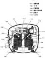
図5は特許文献1に記載された従来の圧縮機の縦断面図、図6は特許文献1に記載された従来の圧縮機の平面断面図、図7は特許文献1に記載された従来の圧縮機の要部拡大断面図、図8は特許文献1に記載された従来の圧縮機の動作説明図である。 5 is a longitudinal sectional view of a conventional compressor described in
図5、図6、図7、図8において、密閉容器1はモータ2と機械部3とからなる圧縮要素4を、複数の弾性支持装置5によって弾性支持し,収容している。モータ2は固定子6と回転子7とからなり、機械部3を駆動する。 5, 6, 7, and 8, the sealed
次に機械部3の主な構成について説明する。 Next, the main structure of the machine part 3 is demonstrated.
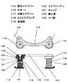
シリンダブロック8は軸受け部9を備えている。シャフト10は主軸部11と偏心部12とを備え、主軸部11はシリンダブロック8の軸受け部9に軸支されるとともに回転子7が圧入固定され、偏心部12は連結機構13により圧縮機構14と連結している。 The
次に弾性支持装置5の構成について説明する。 Next, the configuration of the
弾性支持装置5は、固定スナブバー15とサポート16と可動スナブバー17とコイルスプリング18とから構成されている。固定スナブバー15は密閉容器1の底部に固定されている。可動スナブバー17は、サポート16に設けたスナブバーピン19に圧入固定されており、サポート16はボルト(図示しない)にて、圧縮要素4に固定されている。 The
コイルスプリング18は固定スナブバー15と可動スナブバー17に両端が挟持されている。また、サポート16には可動スナブバー17より外周方向に張り出した当接部20を設けている。 The
以上のように構成された圧縮機について、以下その動作を説明する。 The operation of the compressor configured as described above will be described below.
運転時においては、モータ2に電気が供給されると回転子7が回転し、シャフト10は回転駆動され、シャフト10の回転運動が連結機構13によって圧縮機構14に伝えられ、圧縮動作を行う。 During operation, when electricity is supplied to the motor 2, the
このとき、圧縮機構14で発生する圧縮負荷に応じてモータ2は回転トルクを発生し、圧縮動作を続ける。 At this time, the motor 2 generates rotational torque according to the compression load generated by the
この際、圧縮動作に伴い圧縮要素4は振動するが、弾性支持装置5が、密閉容器1への伝達を減衰し、圧縮機全体の振動を低減する。 At this time, the
また、停止時、モータ2への電気供給が止まると、モータ2が発生していた回転トルクが無くなるので、圧縮機構14で発生する圧縮負荷が連結機構13によって、シャフト10と回転子7にブレーキトルクを与え、回転運動が停止する。その際、ブレーキトルクに応じて、圧縮要素4はシャフト10の主軸部11を略中心として回転子7の回転方向へと回動するが、弾性支持装置5がそのエネルギーを吸収し、回転方向と反回転方向の回転揺動運動を繰り返しながら減衰させることで、密閉容器1への伝達を減衰し、停止時の圧縮機全体の揺動をも低減する。
しかしながら、上記従来の構成では、停止直前の吐出圧力や、吸入圧力が高い場合には圧縮負荷が大きいことから、停止時に回転運動していた回転子7やシャフト10に掛かるブレーキトルクも大きくなり、圧縮要素4の主軸部11を略中心にした回転揺動も大きくなる。 However, in the conventional configuration described above, since the compression load is large when the discharge pressure immediately before the stop or the suction pressure is high, the brake torque applied to the
このとき、回動量が所定の量を超え、図8に示すようにサポート16の当接部20が密閉容器1の内面に当接してしまう場合があり、結果、密閉容器1を衝撃加振し、異常音を発生してしまうといった課題があった。 At this time, the rotation amount exceeds a predetermined amount, and the
一方、圧縮要素の回動量を抑える為に弾性支持装置5のコイルスプリング18のバネ力を上げるといった手法があるが、バネ力を上げると運転時の振動の減衰力が低下するので、圧縮機全体の振動を上げてしまう事になる。 On the other hand, there is a method of increasing the spring force of the
本発明は、上記従来の課題を解決するもので、停止時に圧縮要素が密閉容器へ衝突する際の衝撃力を低減し、異常騒音の発生を低減した圧縮機を提供する事を目的とする。 The present invention solves the above-described conventional problems, and an object of the present invention is to provide a compressor that reduces the impact force when the compression element collides with the hermetic container at the time of stop and reduces the occurrence of abnormal noise.
上記従来の課題を解決するために、本発明の圧縮機は、圧縮要素が前記シャフトを中心に回動したとき密閉容器内に衝突するように、前記圧縮要素側に配置されたスナブバーの外周に前記密閉容器内との当接部を樹脂で形成したもので、停止時に圧縮要素が所定量を越えて回動した場合においても、樹脂で形成した当接部が密閉容器と当接するので、密閉容器への衝撃加振力を低減する作用を有する。 In order to solve the above conventional problems, the compressor of the present invention is provided on the outer periphery of the snubber bar arranged on the compression element side so that the compression element collides with the sealed container when the compression element rotates around the shaft. The abutting portion with the inside of the sealed container is made of resin, and even when the compression element rotates beyond a predetermined amount when stopped, the abutting portion made of resin abuts on the sealed container. It has the effect of reducing the impact excitation force on the container.
本発明の圧縮機は、圧縮要素が所定量以上に回動しても密閉容器への衝撃加振力を低減する事ができるので、停止時の異常騒音の発生を低減した圧縮機を提供することができる。 The compressor of the present invention can reduce the impact excitation force to the sealed container even if the compression element rotates more than a predetermined amount, and thus provides a compressor that reduces the occurrence of abnormal noise when stopped. be able to.
請求項1に記載の発明は、圧縮要素を密閉容器内に弾性的に支持する複数の弾性支持装置を有し、前記弾性支持装置は前記圧縮要素と前記密閉容器にそれぞれ配置されたスナブバーと、前記スナブバーに両端が挟持されるコイルスプリングを備え、前記圧縮要素が前記シャフトを中心に回動したとき前記密閉容器内に衝突するように、前記圧縮要素側に配置されたスナブバーの外周に前記密閉容器内との当接部を樹脂で形成したもので、停止時に圧縮要素が所定量を越えて回動した場合においても、樹脂で形成した当接部が密閉容器と当接するので、樹脂の弾性力により密閉容器への衝撃加振力を減衰、低減し、停止時の異常騒音の発生を低減した圧縮機を提供することができる。 The invention according to
請求項2に記載の発明は、請求項1に記載の発明において、当接部をフッ素系樹脂で形成したもので、化学安定性、耐膨潤性、耐熱性、耐摩耗性に優れているので、冷媒、オイル雰囲気中の高温条件下においても長期間の使用に耐え、請求項1に記載の発明の効果に加えさらに信頼性の高い圧縮機を提供する事ができる。 The invention according to claim 2 is the invention according to
請求項3に記載の発明は、請求項1または請求項2に記載の発明において、圧縮要素側に配置されたスナブバーは、前記圧縮要素に固定されたサポートに立設されたスナブバーピンに、コイルスプリングの内径を保持する挿入部とコイルスプリングの端面を保持するツバ部を有するキャップを備え、前記ツバ部の外径を延出させることで当接部を形成したもので、圧縮要素側に配置されたスナブバーは、サポートに立設されたスナブバーピンにキャップを固定し形成されるとともに、キャップと当接部が一体成形されているので、当接部をサポートに確実に固定でき、横方向の剛性も増すので、当接部が閉容器と当接し横方向の衝撃荷を受けた際の強度を上げることができ、さらには、当接部をキャップに接合する必要もないので、請求項1または請求項2に記載の発明の効果に加えさらに信頼性が高く安価な圧縮機を提供する事ができる。 According to a third aspect of the present invention, in the first or second aspect of the present invention, the snubber bar disposed on the compression element side is connected to a snubber bar pin standing on a support fixed to the compression element. And a cap having a flange portion that holds the end face of the coil spring, and an abutment portion is formed by extending the outer diameter of the flange portion, and is disposed on the compression element side. The snubber bar is formed by fixing the cap to the snubber bar pin standing on the support, and the cap and the abutment part are integrally molded, so the abutment part can be securely fixed to the support and the lateral rigidity is also improved. Therefore, the strength of the contact portion when it comes into contact with the closed container and receives a lateral impact load can be increased, and further, it is not necessary to join the contact portion to the cap. Others can provide a more reliable inexpensive compressor in addition to the effect of the invention according to claim 2.
請求項4に記載の発明は、請求項3に記載の発明において、スナブバーピンはサポートと一体形成されたもので、スナブバーピンがサポートと一体となっている為、スナッパーピンの剛性があがり、当接部が閉容器と当接し横方向の衝撃荷重を受けた際の強度をさらに上げることができ、さらには、スナブバーピンとサポートが一体に成形されるので、請求項3に記載の発明の効果に加えさらに信頼性が高くさらに安価な圧縮機を提供することができる。 The invention according to
請求項5に記載の発明は、請求項3または請求項4に記載の発明において、キャップは回転体形状であるもので、キャップはスナブバーピンを中心軸として回転方向に方向性がないので、組み立て性が向上し、請求項3または請求項4に記載の発明の効果に加えさらに安価な圧縮機を提供することができる。 The invention according to
以下、本発明による圧縮機の実施の形態について、図面を参照しながら説明する。 Embodiments of a compressor according to the present invention will be described below with reference to the drawings.
(実施の形態1)
図1は本発明の実施の形態1における圧縮機の縦断面図、図2は本発明の実施の形態1における圧縮機の平面断面図、図3は本発明の実施の形態1における圧縮機の要部拡大断面図、図4は本発明の実施の形態1における圧縮機の動作説明図である。(Embodiment 1)
1 is a longitudinal sectional view of a compressor according to
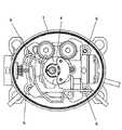
図1、図2、図3、図4において、密閉容器101はモータ102と機械部103とからなる圧縮要素104を、複数の弾性支持装置105によって弾性支持し,収容している。 1, 2, 3, and 4, the sealed
モータ102は固定子106と回転子107とからなり、機械部103を駆動する。 The
次に機械部103の主な構成について説明する。 Next, a main configuration of the
シリンダブロック108は軸受け部109を備えている。シャフト110は主軸部111と偏心部112とを備え、主軸部111はシリンダブロック108の軸受け部109に軸支されるとともに回転子107が圧入固定され、偏心部112は連結機構113により圧縮機構114と連結している。 The
次に弾性支持装置105の構成について説明する。 Next, the configuration of the
弾性支持装置105は、固定スナブバー115とサポート116と可動スナブバー117とコイルスプリング118とから構成されている。固定スナブバー115は密閉容器101の底部に固定されている。可動スナブバー117は、サポート116に固定されており、サポート116はボルト(図示しない)にて、圧縮要素104に固定されている。コイルスプリング118は固定スナブバー115と可動スナブバー117に両端が挟持されている。 The
ここで、圧縮要素104がシャフト110の主軸部111を中心に回動したとき密閉容器101内に衝突するように可動スナブバー117の外周にはサポート116より張り出した樹脂製の当接部119を設けている。 Here, a
ここで当接部119は、フッ素系樹脂、より具体的には四フッ化エチレン樹脂で形成されている。 Here, the
また、可動スナブバー117はサポート116に設けたスナブバーピン120と、スナブバーピン120に圧入固定されたキャップ121とから成り、キャップ121にはコイルスプリング118の内径を保持する挿入部122とコイルスプリング118の端面を保持するツバ部123とを有し、ツバ部123の外径を延出させることで当接部119を形成している。 The
スナブバーピン120はサポート116とプレス等により一体形成されている。また、キャップ121はスナブバーピン120を軸とした回転体形状である。 The
以上のように構成された圧縮機について、以下その動作を説明する。 The operation of the compressor configured as described above will be described below.
運転時においては、モータ102に電気が供給されると回転子107が回転し、シャフト110は回転駆動され、シャフト110の回転運動が連結機構113によって圧縮機構114に伝えられ、圧縮動作を行う。 During operation, when electricity is supplied to the
このとき、圧縮機構114で発生する圧縮負荷に応じてモータ102は回転トルクを発生し、圧縮動作を続ける。 At this time, the
この際、圧縮動作に伴い圧縮要素104は振動するが、弾性支持装置105が、密閉容器101への伝達を減衰し、圧縮機全体の振動を低減する。 At this time, the
また、停止時、モータ102への電気供給が止まると、モータ102が発生していた回転トルクが無くなるので、圧縮機構114で発生する圧縮負荷が連結機構113によって、シャフト110と回転子107にブレーキトルクを与え、回転運動が停止する。その際、ブレーキトルクに応じて、圧縮要素104はシャフト110の主軸部111を略中心として回転子107の回転方向へと回動するが、弾性支持装置105がそのエネルギーを吸収し、回転方向と反回転方向の回転揺動運動を繰り返しながら減衰させることで、密閉容器101への伝達を減衰し、停止時の圧縮機全体の揺動をも低減する。 Further, when the electric supply to the
ここで、停止直前の吐出圧力や、吸入圧力が高い場合には、圧縮負荷が大きいことから、停止時に回転運動していた回転子107とシャフト110に掛かるブレーキトルクも大きくなり、圧縮要素104の主軸部111を略中心にした回転揺動も大きくなる。 Here, when the discharge pressure immediately before the stop or the suction pressure is high, the compression load is large, so that the brake torque applied to the
このとき、回動量が所定の量を超え、図4に示すように当接部119が密閉容器101の内面に当接してしまうが、当接部119は樹脂で形成されているので、樹脂の弾性力により密閉容器101への衝撃伝達を減衰し、密閉容器101への加振力を低減する。従って、停止時の異常騒音の発生を低減した圧縮機を提供することができる。 At this time, the rotation amount exceeds a predetermined amount, and the
また、当接部119をフッ素系樹脂、より具体的には四フッ化エチレン樹脂で形成しているので、化学安定性、耐膨潤性、耐熱性、耐摩耗性に優れているので、冷媒、オイル雰囲気中の高温条件下においても長期間の使用に耐える。従って、さらに信頼性の高い圧縮機を提供する事ができる。 Further, since the
ここで、当接部119はキャップ121と一体成型され、サポート116に設けたスナブバーピン120に圧入固定されているので、当接部119をサポート116に確実に固定でき、横方向の剛性も増す。その結果、当接部119が密閉容器101と当接し横方向の衝撃荷重を受けた際の強度を上げることができる。さらには、当接部119とキャップ121が射出成型等により一体で形成されているので、当接部119をキャップ121に接合する必要もない。従って、さらに信頼性が高く安価な圧縮機を提供する事ができる。 Here, since the
また、スナブバーピン120はサポート116とプレス等により一体形成されているのでスナブバーピン120とサポート116との接合部がなく、スナブバーピン120の剛性が上がる。その結果、当接部119が密閉容器101と当接し横方向の衝撃荷を受けた際の強度をさらに上げることができる。 Further, since the
さらには、スナブバーピン120とサポート116が一体に成形されるので、スナブバーピン120とサポート116との接合の工数が削減できる。従って、さらに信頼性が高く、さらに安価な圧縮機を提供することができる。 Furthermore, since the
また、キャップ121はスナブバーピン120を中心軸とした回転体形状であるので、キャップ121をスナブバーピン120に圧入する際に、回転方向に方向性がない。その結果、組み立て性が向上する。従って、さらに安価な圧縮機を提供することができる。 Further, since the
以上のように、本発明にかかる圧縮機は、負荷が高い場合に停止しても、密閉容器への衝撃加振力を低減し、停止時の異常騒音の発生を低減した圧縮機を提供することができるので、負荷の高い業務用や空調用の用途にも適用できる。 As described above, the compressor according to the present invention provides a compressor that reduces the impact excitation force to the hermetic container even when the load is high, and reduces the occurrence of abnormal noise when stopped. Therefore, it can be applied to high-load business use and air conditioning use.
101 密閉容器
102 モータ
104 圧縮要素
105 弾性支持装置
107 回転子
110 シャフト
115 固定スナブバー
116 サポート
117 可動スナブバー
118 コイルスプリング
119 当接部
120 スナブバーピン
121 キャップ
122 挿入部
123 ツバ部DESCRIPTION OF
Claims (5)
Translated fromJapanesePriority Applications (1)
| Application Number | Priority Date | Filing Date | Title |
|---|---|---|---|
| JP2006123246AJP2007292022A (en) | 2006-04-27 | 2006-04-27 | Compressor |
Applications Claiming Priority (1)
| Application Number | Priority Date | Filing Date | Title |
|---|---|---|---|
| JP2006123246AJP2007292022A (en) | 2006-04-27 | 2006-04-27 | Compressor |
Publications (1)
| Publication Number | Publication Date |
|---|---|
| JP2007292022Atrue JP2007292022A (en) | 2007-11-08 |
Family
ID=38762865
Family Applications (1)
| Application Number | Title | Priority Date | Filing Date |
|---|---|---|---|
| JP2006123246APendingJP2007292022A (en) | 2006-04-27 | 2006-04-27 | Compressor |
Country Status (1)
| Country | Link |
|---|---|
| JP (1) | JP2007292022A (en) |
- 2006
- 2006-04-27JPJP2006123246Apatent/JP2007292022A/enactivePending
Similar Documents
| Publication | Publication Date | Title |
|---|---|---|
| AU2007230458B2 (en) | Compressor | |
| EP3242026B1 (en) | Linear compressor | |
| CN101184919B (en) | Electric compressor | |
| JP2008151104A (en) | Reciprocating compressor crankshaft | |
| JP2009041393A (en) | Hermetic electric compressor | |
| JP4753731B2 (en) | Rotary compressor and refrigeration cycle apparatus using the same | |
| JP2010229833A (en) | Hermetic compressor | |
| CN209943101U (en) | Compressor with a compressor housing having a plurality of compressor blades | |
| CN100416098C (en) | Cylinder support structure of reciprocating compressor | |
| JP2007292021A (en) | Compressor support device | |
| JP2007292022A (en) | Compressor | |
| JP5235962B2 (en) | Scroll compressor | |
| JP2008121554A (en) | Compressor | |
| KR101164489B1 (en) | Hermetic compressor | |
| JP2006144578A (en) | Expander integrated compressor | |
| JP6686994B2 (en) | Scroll compressor | |
| JP2010101278A (en) | Hermetic compressor | |
| CN116457578B (en) | Scroll compressor and refrigeration cycle device | |
| JP2009085194A (en) | Hermetic compressor | |
| CN220415615U (en) | Compressor of movable refrigerator | |
| KR101214484B1 (en) | Crankshaft supporting device for compressor | |
| KR102861984B1 (en) | Scroll compressor | |
| KR101366566B1 (en) | A hermetic type compressor | |
| KR101366563B1 (en) | A reciprocating compressor | |
| JP2010242590A (en) | Hermetic compressor |