JP2007292011A - Liquid feed pump and liquid chromatograph using the liquid feed pump - Google Patents
Liquid feed pump and liquid chromatograph using the liquid feed pumpDownload PDFInfo
- Publication number
- JP2007292011A JP2007292011AJP2006123135AJP2006123135AJP2007292011AJP 2007292011 AJP2007292011 AJP 2007292011AJP 2006123135 AJP2006123135 AJP 2006123135AJP 2006123135 AJP2006123135 AJP 2006123135AJP 2007292011 AJP2007292011 AJP 2007292011A
- Authority
- JP
- Japan
- Prior art keywords
- plunger
- crosshead
- liquid feed
- feed pump
- holder
- Prior art date
- Legal status (The legal status is an assumption and is not a legal conclusion. Google has not performed a legal analysis and makes no representation as to the accuracy of the status listed.)
- Pending
Links
Images


Landscapes
- Reciprocating Pumps (AREA)
Abstract
Translated fromJapaneseDescription
Translated fromJapanese本発明は、例えば液体クロマトグラフなどに用いる送液ポンプに関し、特にプランジャの先端部分をポンプ室内で往復運動させて送液を行なうプランジャポンプに関するものである。 The present invention relates to a liquid feed pump used in, for example, a liquid chromatograph, and more particularly to a plunger pump that feeds liquid by reciprocating a tip portion of a plunger in a pump chamber.
従来のプランジャポンプを説明する。図4は従来のプランジャポンプを示す断面図であり、(B),(C)はプランジャ部分の挙動を示す図である。 A conventional plunger pump will be described. FIG. 4 is a sectional view showing a conventional plunger pump, and (B) and (C) are views showing the behavior of the plunger portion.
ポンプボディ10は、液をポンプ室16内に吸入するための吸入流路12と、吸入した液を送液するための送液流路14を備えている。12a及び14aは吸入流路12と送液流路14に設けられた逆止弁である。ポンプ室16にはシール材18を通してプランジャ34の先端部分が挿入されている。プランジャ34は、ポンプボディ10内に離間して配置されたすべり軸受24,26に保持されたクロスヘッド32に従動するようにクロスヘッド32の先端側に回動可能に取り付けられている。クロスヘッド32はポンプボディ10に固着されたバネ22の弾性力によって常時基端側に押されており、クロスヘッド32の基端側にカム20の周面上を摺動するカムフォロワ38が設けられている。これにより、クロスヘッド32とプランジャ34はカム20が回転することで左右方向に往復運動する。 The
プランジャ34の基端側にプランジャホルダー36が固着されている。プランジャホルダー36はクロスヘッド32の先端側に空洞部分として設けられたプランジャ保持部33の内部のリング状の保持部材35と係合し、プランジャ保持部33の内部に保持されている。プランジャホルダー36の保持部材35と接する面は球面状であり、保持部材35のプランジャホルダー36と接する面はプランジャホルダー36の球面に対応する凹形状である。さらに、プランジャ34の基端部端面は球面状であり、その端面がクロスヘッド32の空洞部分内部の壁面に当接してその壁面に対して摺動することができるようになっている。これにより、プランジャ34はクロスヘッド32に対してプランジャホルダー36を中心とする回転方向にある程度の自由度をもっている。 A
クロスヘッド32は離間して配置されたすべり軸受24,26に保持された状態で往復運動するため、クロスヘッド32とすべり軸受24,26との間の摩擦によって磨耗粉が出る。この磨耗粉がクロスヘッド32とすべり軸受24,26との間に溜まるとクロスヘッド32の摺動の妨げになるため、磨耗粉の排出を目的としてクロスヘッド32とすべり軸受24,26の間に隙間が設けられている。 Since the
クロスヘッド32とすべり軸受24,26との間に隙間が設けられていることで、クロスヘッド32が左右方向に往復運動する際、カム20の圧力角の影響(クロスヘッド32は前進時にはカム20によって上方向に押し出される力が働き、後退時にはバネ22によって下方向に押される力が働くこと)によって、例えば図4(B),(C)に示されるように上下方向に揺れ動き、プランジャ保持部33の位置が上下に変動する。すなわち、プランジャホルダー36の位置が上下に変動し、これに起因してプランジャ34が傾斜する。その結果、プランジャ34とシール材18の接触状態が変動し、シール材18の磨耗が促進されて寿命が低下する。 Since the clearance is provided between the
プランジャ34にクロスヘッド32に対する回転方向の自由度を与えて、クロスヘッド32が揺れ動いても往復運動させることができるようにすることは他にも提案されている(例えば、特許文献1参照。)。
プランジャホルダー36に回転方向の自由度を与えただけでは、プランジャ保持部33の位置が上下に変動することによって生じるプランジャ34の傾斜をなくすことはできない。プランジャ保持部33の変動の影響を小さくするためには、プランジャホルダー36をプランジャ保持部33に対して上下方向への平行移動の自由度をもたせることが考えられる。しかし、平行移動の自由度を与えるためには面と面のすべりを利用する必要があり、このことはプランジャホルダー36及びプランジャ34のクロスヘッド32に対する追従性が悪くなることにつながり、結果的にシール寿命にばらつきが生じるという問題が生じる。 By simply providing the
そこで本発明は、クロスヘッドに対するプランジャの追従性を低下させることなくプランジャの往復運動を安定して行なわせ、ポンプ室入口に設けられたプランジャ用シール材の長寿命化を図ることを目的としている。 Accordingly, an object of the present invention is to stabilize the reciprocating motion of the plunger without deteriorating the followability of the plunger with respect to the cross head, and to extend the life of the plunger sealing material provided at the pump chamber inlet. .
本発明の送液ポンプは、ポンプボディ内部に摺動可能に保持され、カムの回転に追従して往復運動するクロスヘッドと、基端側にプランジャホルダーを備え、クロスヘッド内部に設けられたプランジャ保持部にそのプランジャホルダーが回転可能に保持されてクロスヘッドに従動するプランジャと、プランジャの先端部分がシール部材を通して挿入されたポンプ室と、を備えた送液ポンプであって、プランジャホルダーはクロスヘッドの往復運動における揺れ動きの中心位置に配置されていることを特徴とするものである。
クロスヘッドの往復運動方向におけるクロスヘッドの中央部分にプランジャ保持部を設けることで、クロスヘッドの揺れ動きの中心部分、すなわちクロスヘッドの揺れ動きに起因した位置の変動の小さい位置にプランジャの挙動の中心であるプランジャホルダーを保持することができる。The liquid feed pump of the present invention includes a crosshead that is slidably held inside the pump body and reciprocates following the rotation of the cam, a plunger holder on the base end side, and a plunger provided inside the crosshead. A liquid feed pump comprising: a plunger whose plunger holder is rotatably held by a holding portion and driven by a cross head; and a pump chamber in which a tip portion of the plunger is inserted through a seal member. It is arranged at the center position of the shaking motion in the reciprocating motion of the head.
By providing a plunger holder at the center of the crosshead in the reciprocating direction of the crosshead, the center of the plunger moves to the center of the crosshead swaying movement, that is, to the position where the position fluctuation due to the swaying movement of the crosshead is small. A plunger holder can be held.
ポンプボディ内部に2つのすべり軸受が離間して配置され、クロスヘッドは常時2つのすべり軸受の間にプランジャ保持部が位置するようにすべり軸受に保持されており、プランジャホルダーの配置位置は上記2つのすべり軸受の中間位置となっているのが好ましい。 The two slide bearings are spaced apart from each other inside the pump body, and the crosshead is always held by the slide bearing so that the plunger holding portion is located between the two slide bearings. It is preferably in the middle position between the two plain bearings.
プランジャホルダーの好ましい形態の一例は、プランジャの基端部に着脱可能に取り付けられた球体である。 An example of a preferable form of the plunger holder is a sphere removably attached to the proximal end portion of the plunger.
本発明の液体クロマトグラフは、分析流路に移動相を供給する移動相供給部と、分析流路中に試料を注入するための試料注入部と、試料注入部に注入された試料の分離を行なう分離カラムと、分離カラムで分離された試料を検出する検出部と、を備えた液体クロマトグラフであって、移動相供給部は本発明の送液ポンプを備えていることを特徴とする。 The liquid chromatograph of the present invention includes a mobile phase supply unit for supplying a mobile phase to an analysis channel, a sample injection unit for injecting a sample into the analysis channel, and separation of a sample injected into the sample injection unit. A liquid chromatograph comprising a separation column to be performed and a detection unit for detecting a sample separated by the separation column, wherein the mobile phase supply unit includes the liquid feed pump of the present invention.
本発明の送液ポンプは、クロスヘッドの往復運動における揺れ動きの中心位置にプランジャ保持部が設けられているので、プランジャホルダーがクロスヘッドの揺れ動きの中心位置で保持され、クロスヘッドの揺れ動きの中心とプランジャの挙動の中心が一致する。これにより、プランジャの挙動の中心は安定した往復運動を行なうようになるので、プランジャの往復運動が安定して行なわれ、ポンプ室入口のシール材とプランジャとの接触状態が安定し、シール材の極度な磨耗がなくなってシール材の寿命を安定させることができる。 In the liquid feed pump of the present invention, since the plunger holding portion is provided at the center position of the swing motion in the reciprocating motion of the cross head, the plunger holder is held at the center position of the swing motion of the cross head, and the center of the swing motion of the cross head is The center of plunger behavior matches. As a result, the center of the plunger behavior is reciprocated stably, so that the plunger reciprocates stably, the contact state between the seal material at the pump chamber inlet and the plunger is stable, and the seal material Extreme wear is eliminated and the life of the sealing material can be stabilized.
ポンプボディ内部にクロスヘッドを保持する2つのすべり軸受が離間して配置されている場合、クロスヘッドが常時2つのすべり軸受の間にプランジャ保持部が位置するようにすべり軸受に保持され、プランジャホルダーの配置位置は上記2つのすべり軸受の中間位置となっていれば、クロスヘッドの揺れ動きの中心部分でプランジャホルダーを保持することができるので、プランジャの挙動が安定する。 When two slide bearings that hold the cross head are arranged apart from each other inside the pump body, the cross head is always held by the slide bearing so that the plunger holding portion is located between the two slide bearings. Since the plunger holder can be held at the center portion of the swing motion of the cross head if the position of is the intermediate position between the two sliding bearings, the behavior of the plunger is stabilized.
図1は本発明の送液ポンプの一実施例を示す断面図であり、(B),(C)はプランジャ部分の挙動を示す断面図である。
ポンプボディ10は、液をポンプ室16内に吸入するための吸入流路12と、吸入した液を送液するための送液流路14を備えている。12a及び14aは吸入流路12と送液流路14に設けられた逆止弁である。ポンプ室16入口にシール材18が設けられており、シール材18を通してプランジャ4の先端部分が挿入されている。FIG. 1 is a cross-sectional view showing an embodiment of the liquid feed pump of the present invention, and (B) and (C) are cross-sectional views showing the behavior of the plunger portion.
The
2はカム20の回転によって往復運動するクロスヘッドである。クロスヘッド2は基端部にカム20の周面に追従するカムフォロワ8を備えている。クロスヘッド2はポンプボディ10内に離間して配置されたすべり軸受24,26に保持されている。クロスヘッド2はポンプボディ10に固着されたバネ22の弾性力によって常時基端側に押されている。クロスヘッド2はカム20が回転することで左右方向に往復運動する。クロスヘッド2内部ですべり軸受24,26の外側からほぼ等距離にあるすべり軸受24,26の中間部にリング状の保持部材5を備えたプランジャ保持部3が設けられている。プランジャ保持部3は常時すべり軸受24と26の間に位置するように配置されている。
すべり軸受24,26としては、例えば潤滑油を含んだ樹脂からなる中空円筒状のベアリングを用いることができる。A
As the
プランジャ4の基端側に球体からなるプランジャホルダー6がプランジャ4の基端に設けられたピンに差し込まれて、着脱可能に取り付けられている。プランジャホルダー6はクロスヘッド2のプランジャ保持部3内部の保持部材5と係合するとともにプランジャ保持部3内部の壁面に接しながらプランジャ保持部3に回転可能に保持されている。すなわち、プランジャ4はクロスヘッド2に対して従動するとともに一定範囲内において回転方向への自由度をもっている。プランジャ4の回転の中心はプランジャホルダー6である。 A
クロスヘッド2とすべり軸受24,26との間には磨耗粉排出のための隙間が設けられている。そのため、図1(B),(C)に示されるように、クロスヘッド2は圧力角の影響によって傾斜し、上下に揺れ動きながら往復運動する。クロスヘッド2の揺れ動きの中心はすべり軸受24と26の中間部に存在する。クロスヘッド2の揺れ動きの中心とは、ここでは上下方向への位置の変動が最も小さい位置であることを意味する。プランジャホルダー6を保持するプランジャ保持部3もすべり軸受24と26の中間部に設けられているので、プランジャ4の挙動の中心であるプランジャホルダー6の位置とクロスヘッド2の揺れ動きの中心位置がほぼ一致する。したがって、プランジャ4の挙動の中心はクロスヘッド2の揺れ動きの影響をほとんど受けることなく挙動が安定し、プランジャ4の往復運動が安定して行なわれる。これにより、プランジャ4とシール材18の接触状態が安定するので、シール材18の極端な磨耗がなくなり、寿命を延ばすことができる。 A gap is provided between the
また、本発明の送液ポンプはこの実施例に限定されるものではない。例えば図2に示された送液ポンプは、図1に示された送液ポンプとは異なるプランジャ部分を備えたものである。すなわち、ポンプヘッド10内部に摺動可能に配置され、カム20に追従するカムフォロワ8aを備えてカム20が回転することによって往復運動するクロスヘッド2aは、その中央部分のプランジャ保持部3aでプランジャ4aの基端側に固着された球体ではないプランジャホルダー6aを保持している。プランジャ保持部3aはプランジャ4aと係合するリング状の保持部材5aを備えている。プランジャホルダー6aの保持部材5aに対向する面は球面状となっており、保持部材5aのプランジャホルダー6aに接する面はプランジャホルダー6aの球面状の面に対応する凹形状になっている。これにより、プランジャホルダー6aは保持部材5aの対向面上を摺動する。プランジャ4aの基端側先端部は球面状となっており、プランジャ保持部3a内部の壁面に接している。この構造により、プランジャ4aはクロスヘッド2aに保持されながらもクロスヘッド2aに対して回転方向に自由度をもっており、その回転の中心はクロスヘッド2aの揺れ動きの中心とほぼ一致する。この場合も図1の実施例と同様に、プランジャホルダー6aの位置は、クロスヘッド2aの揺れ動きの中心位置とほぼ一致するように、すべり軸受24,26の中間部の位置に設定されている。 Further, the liquid feed pump of the present invention is not limited to this embodiment. For example, the liquid feed pump shown in FIG. 2 includes a plunger portion different from the liquid feed pump shown in FIG. That is, the
図1に示した送液ポンプの動作を説明する。
図1(A)に示されるように、プランジャ4の先端部分がポンプ室16内に押し込まれてポンプ室16内の空間が押し潰された状態(以下、上死点という。)からカム20の回転によってプランジャ4が徐々に基端側に移動して後退し、ポンプ室16内に空間ができる。ポンプ室16内にできた空間の圧力は吸引により減圧となるため、圧力差の関係によって逆止弁12aは開いて逆止弁14aは閉じ、吸入流路12から送液対象である移動相が供給される。この動作は、(C)に示されるように、プランジャ4が最も後退し、ポンプ室16内にできた空間が最大となる状態(以下、下死点という。)まで行なわれ、その空間内に移動相が貯留される。The operation of the liquid feed pump shown in FIG. 1 will be described.
As shown in FIG. 1A, the
下死点を越えると、プランジャ4は徐々に先端側に移動して前進し、プランジャ4の先端部分がポンプ室16内の空間を押しつぶしていく。これにより、ポンプ室16内の圧力は上昇して逆止弁12aは閉じて逆止弁14aは開くので、ポンプ室16の空間内に貯留されていた移動相は送液流路14へと押し出されていく。この動作は(A)の上死点の状態になるまで行なわれ、ポンプ室16内に貯留されていた移動相が送液流路14側に押し出される。
さらに、上死点を越えた後は同じ動作が繰り返し行なわれ、移動相が吸入流路12側から送液流路14側へ送液される。When the bottom dead center is exceeded, the
Further, after the top dead center is exceeded, the same operation is repeated, and the mobile phase is sent from the
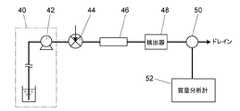
次に、本発明の送液ポンプを用いた液体クロマトグラフの一実施例を説明する。図3は液体クロマトグラフの一実施例を示す概略構成図である。
分析流路に移動相として溶離液を供給するための移動相供給部40が配置されている。さらに分析流路上に、分析流路中に試料を注入するための試料注入部44と、分析流路中に注入された試料を分離するための分離カラム46と、分離カラム46で分離された試料成分を検出する紫外、吸光度計などの検出器48と、分析流路をドレイン側と他の検出器としての質量分析計52側に選択的に接続する流路切替バルブ50とを備えている。Next, an example of a liquid chromatograph using the liquid feed pump of the present invention will be described. FIG. 3 is a schematic configuration diagram showing an embodiment of a liquid chromatograph.
A mobile
移動相供給部40は溶離液を送液するための送液ポンプ42を備えている。送液ポンプ42は、例えば図1や図2に示された本発明の送液ポンプである。送液ポンプ42の構成は、1つの送液ポンプが図1や図2に示された送液ポンプ機構を1つだけ備えたものであってもよいし、同じポンプ機構を2つ備え、1つのモータで位相の異なるそれぞれのカム20を駆動するダブルプランジャ方式のものであってもよい。 The mobile
2,2a クロスヘッド
3,3a プランジャ保持部
4,4a プランジャ
5,5a 保持部材
6,6a プランジャホルダー
8,8a カムフォロワ
10 ポンプボディ
12 吸入流路
12a,14a 逆止弁
14 送液流路
16 ポンプ室
18 シール材
20 カム
22 ばね
24,26 すべり軸受
40 移動相供給部
42 送液ポンプ
44 試料注入部
46 分離カラム
48 検出器
50 流路切替バルブ
52 質量分析計2,
Claims (4)
Translated fromJapanese前記プランジャホルダーは前記クロスヘッドの往復運動における揺れ動きの中心位置に配置されていることを特徴とする送液ポンプ。A crosshead that is slidably held inside the pump body and reciprocates following the rotation of the cam, and a plunger holder on the base end side. The plunger holder In a liquid feed pump comprising: a plunger that is rotatably held and is driven by the crosshead; and a pump chamber in which a tip portion of the plunger is inserted through a seal member.
The liquid feed pump according to claim 1, wherein the plunger holder is disposed at a center position of a shaking motion in the reciprocating motion of the cross head.
前記移動相供給部は請求項1から3のいずれかに記載の送液ポンプを備えていることを特徴とする液体クロマトグラフ。
A mobile phase supply section for supplying a mobile phase to the analysis flow path; a sample injection section for injecting a sample into the analysis flow path; a separation column for separating the sample injected into the sample injection section; In a liquid chromatograph comprising a detection unit for detecting a sample separated by a separation column,
A liquid chromatograph, wherein the mobile phase supply unit includes the liquid feeding pump according to any one of claims 1 to 3.
Priority Applications (1)
| Application Number | Priority Date | Filing Date | Title |
|---|---|---|---|
| JP2006123135AJP2007292011A (en) | 2006-04-27 | 2006-04-27 | Liquid feed pump and liquid chromatograph using the liquid feed pump |
Applications Claiming Priority (1)
| Application Number | Priority Date | Filing Date | Title |
|---|---|---|---|
| JP2006123135AJP2007292011A (en) | 2006-04-27 | 2006-04-27 | Liquid feed pump and liquid chromatograph using the liquid feed pump |
Publications (1)
| Publication Number | Publication Date |
|---|---|
| JP2007292011Atrue JP2007292011A (en) | 2007-11-08 |
Family
ID=38762856
Family Applications (1)
| Application Number | Title | Priority Date | Filing Date |
|---|---|---|---|
| JP2006123135APendingJP2007292011A (en) | 2006-04-27 | 2006-04-27 | Liquid feed pump and liquid chromatograph using the liquid feed pump |
Country Status (1)
| Country | Link |
|---|---|
| JP (1) | JP2007292011A (en) |
Cited By (4)
| Publication number | Priority date | Publication date | Assignee | Title |
|---|---|---|---|---|
| WO2011050586A1 (en)* | 2009-10-30 | 2011-05-05 | 北京普析通用仪器有限责任公司 | Serial-parallel liquid-phase chromatographic pump |
| WO2012147477A1 (en) | 2011-04-27 | 2012-11-01 | シーケーディ株式会社 | Multilayer diaphragm |
| WO2012147476A1 (en) | 2011-04-27 | 2012-11-01 | シーケーディ株式会社 | Liquid feed pump and flow rate control device |
| JP2015017590A (en)* | 2013-07-12 | 2015-01-29 | 三菱重工業株式会社 | Rotating machine |
Citations (3)
| Publication number | Priority date | Publication date | Assignee | Title |
|---|---|---|---|---|
| JPH06108966A (en)* | 1992-09-28 | 1994-04-19 | Tosoh Corp | pump |
| JP2005221405A (en)* | 2004-02-06 | 2005-08-18 | Shimadzu Corp | Chromatographic analyzer |
| JP2005274391A (en)* | 2004-03-25 | 2005-10-06 | Shimadzu Corp | Liquid chromatograph pump |
- 2006
- 2006-04-27JPJP2006123135Apatent/JP2007292011A/enactivePending
Patent Citations (3)
| Publication number | Priority date | Publication date | Assignee | Title |
|---|---|---|---|---|
| JPH06108966A (en)* | 1992-09-28 | 1994-04-19 | Tosoh Corp | pump |
| JP2005221405A (en)* | 2004-02-06 | 2005-08-18 | Shimadzu Corp | Chromatographic analyzer |
| JP2005274391A (en)* | 2004-03-25 | 2005-10-06 | Shimadzu Corp | Liquid chromatograph pump |
Cited By (9)
| Publication number | Priority date | Publication date | Assignee | Title |
|---|---|---|---|---|
| WO2011050586A1 (en)* | 2009-10-30 | 2011-05-05 | 北京普析通用仪器有限责任公司 | Serial-parallel liquid-phase chromatographic pump |
| CN102052276B (en)* | 2009-10-30 | 2013-09-11 | 北京普析通用仪器有限责任公司 | Series-parallel connection liquid chromatogram pump |
| WO2012147477A1 (en) | 2011-04-27 | 2012-11-01 | シーケーディ株式会社 | Multilayer diaphragm |
| WO2012147476A1 (en) | 2011-04-27 | 2012-11-01 | シーケーディ株式会社 | Liquid feed pump and flow rate control device |
| CN103429894A (en)* | 2011-04-27 | 2013-12-04 | Ckd株式会社 | Multilayer diaphragm |
| US8807014B2 (en) | 2011-04-27 | 2014-08-19 | Ckd Corporation | Multi-layer diaphragm |
| US8888471B2 (en) | 2011-04-27 | 2014-11-18 | Ckd Corporation | Liquid feed pump and flow control device |
| CN103429894B (en)* | 2011-04-27 | 2016-06-29 | Ckd株式会社 | Laminated diaphragm |
| JP2015017590A (en)* | 2013-07-12 | 2015-01-29 | 三菱重工業株式会社 | Rotating machine |
Similar Documents
| Publication | Publication Date | Title |
|---|---|---|
| CN106104267B (en) | Seal moving with piston in high pressure pump | |
| WO2016103554A1 (en) | Variable length connecting rod and variable compression ratio internal combustion engine | |
| US20100012682A1 (en) | Pumps and Methods for Using the Same | |
| JP2007292011A (en) | Liquid feed pump and liquid chromatograph using the liquid feed pump | |
| US9803628B2 (en) | Compressor with drive and tilt mechanisms located on the same side of a swash plate | |
| CN108474337B (en) | High-pressure pump with pump spring sealing sleeve | |
| CN110418693B (en) | Rotary clamping device | |
| WO2016038753A1 (en) | Hydraulic lash adjuster | |
| JP4086001B2 (en) | Liquid chromatograph pump | |
| US9133943B2 (en) | Flow path switching valve and discharge control apparatus for fluid material using the same | |
| WO2021022650A1 (en) | Pumping device | |
| JP2008101508A (en) | Reciprocating compressor | |
| JP6424965B2 (en) | Check valve and liquid pump | |
| JP2015098855A (en) | Diaphragm pump | |
| KR101777183B1 (en) | Variable-capacity swash plate-type compressor | |
| JP6141930B2 (en) | Capacity control valve | |
| US9784259B2 (en) | Variable displacement swash plate type compressor | |
| US20170218796A1 (en) | Hydraulic lash adjuster and method for using hydraulic lash adjuster | |
| JP6032146B2 (en) | Double-head piston type swash plate compressor | |
| JP2010285898A (en) | Variable capacity compressor | |
| CN116255334B (en) | Sliding structure and compressor | |
| KR102868746B1 (en) | Variable Capacity External Control Valve | |
| JP2001099057A (en) | Swash plate compressor | |
| JP2007136412A (en) | Trigger type liquid injector | |
| KR102818412B1 (en) | Variable Capacity External Control Valve |
Legal Events
| Date | Code | Title | Description |
|---|---|---|---|
| A621 | Written request for application examination | Effective date:20080801 Free format text:JAPANESE INTERMEDIATE CODE: A621 | |
| A977 | Report on retrieval | Effective date:20101227 Free format text:JAPANESE INTERMEDIATE CODE: A971007 | |
| A131 | Notification of reasons for refusal | Free format text:JAPANESE INTERMEDIATE CODE: A131 Effective date:20110125 | |
| A521 | Written amendment | Effective date:20110328 Free format text:JAPANESE INTERMEDIATE CODE: A523 | |
| A02 | Decision of refusal | Effective date:20111004 Free format text:JAPANESE INTERMEDIATE CODE: A02 |