JP2007291937A - Protective member structure of heat exchanger for vehicles - Google Patents
Protective member structure of heat exchanger for vehiclesDownload PDFInfo
- Publication number
- JP2007291937A JP2007291937AJP2006120316AJP2006120316AJP2007291937AJP 2007291937 AJP2007291937 AJP 2007291937AJP 2006120316 AJP2006120316 AJP 2006120316AJP 2006120316 AJP2006120316 AJP 2006120316AJP 2007291937 AJP2007291937 AJP 2007291937A
- Authority
- JP
- Japan
- Prior art keywords
- heat exchanger
- vehicle
- protection
- member structure
- protective member
- Prior art date
- Legal status (The legal status is an assumption and is not a legal conclusion. Google has not performed a legal analysis and makes no representation as to the accuracy of the status listed.)
- Withdrawn
Links
- 230000001681protective effectEffects0.000titleclaimsabstractdescription31
- 230000000694effectsEffects0.000description5
- 238000010586diagramMethods0.000description4
- 239000000470constituentSubstances0.000description3
- 230000015572biosynthetic processEffects0.000description2
- 238000005219brazingMethods0.000description2
- 230000008878couplingEffects0.000description2
- 238000010168coupling processMethods0.000description2
- 238000005859coupling reactionMethods0.000description2
- 239000000463materialSubstances0.000description2
- XAGFODPZIPBFFR-UHFFFAOYSA-NaluminiumChemical compound[Al]XAGFODPZIPBFFR-UHFFFAOYSA-N0.000description1
- 229910052782aluminiumInorganic materials0.000description1
- 238000005516engineering processMethods0.000description1
- 238000010438heat treatmentMethods0.000description1
- 238000010030laminatingMethods0.000description1
- 239000011347resinSubstances0.000description1
- 229920005989resinPolymers0.000description1
- 239000004575stoneSubstances0.000description1
Images


Classifications
- F—MECHANICAL ENGINEERING; LIGHTING; HEATING; WEAPONS; BLASTING
- F28—HEAT EXCHANGE IN GENERAL
- F28D—HEAT-EXCHANGE APPARATUS, NOT PROVIDED FOR IN ANOTHER SUBCLASS, IN WHICH THE HEAT-EXCHANGE MEDIA DO NOT COME INTO DIRECT CONTACT
- F28D1/00—Heat-exchange apparatus having stationary conduit assemblies for one heat-exchange medium only, the media being in contact with different sides of the conduit wall, in which the other heat-exchange medium is a large body of fluid, e.g. domestic or motor car radiators
- F28D1/02—Heat-exchange apparatus having stationary conduit assemblies for one heat-exchange medium only, the media being in contact with different sides of the conduit wall, in which the other heat-exchange medium is a large body of fluid, e.g. domestic or motor car radiators with heat-exchange conduits immersed in the body of fluid
- F28D1/03—Heat-exchange apparatus having stationary conduit assemblies for one heat-exchange medium only, the media being in contact with different sides of the conduit wall, in which the other heat-exchange medium is a large body of fluid, e.g. domestic or motor car radiators with heat-exchange conduits immersed in the body of fluid with plate-like or laminated conduits
- F28D1/0308—Heat-exchange apparatus having stationary conduit assemblies for one heat-exchange medium only, the media being in contact with different sides of the conduit wall, in which the other heat-exchange medium is a large body of fluid, e.g. domestic or motor car radiators with heat-exchange conduits immersed in the body of fluid with plate-like or laminated conduits the conduits being formed by paired plates touching each other
- F28D1/0325—Heat-exchange apparatus having stationary conduit assemblies for one heat-exchange medium only, the media being in contact with different sides of the conduit wall, in which the other heat-exchange medium is a large body of fluid, e.g. domestic or motor car radiators with heat-exchange conduits immersed in the body of fluid with plate-like or laminated conduits the conduits being formed by paired plates touching each other the plates having lateral openings therein for circulation of the heat-exchange medium from one conduit to another
- F28D1/0333—Heat-exchange apparatus having stationary conduit assemblies for one heat-exchange medium only, the media being in contact with different sides of the conduit wall, in which the other heat-exchange medium is a large body of fluid, e.g. domestic or motor car radiators with heat-exchange conduits immersed in the body of fluid with plate-like or laminated conduits the conduits being formed by paired plates touching each other the plates having lateral openings therein for circulation of the heat-exchange medium from one conduit to another the plates having integrated connecting members
- F—MECHANICAL ENGINEERING; LIGHTING; HEATING; WEAPONS; BLASTING
- F28—HEAT EXCHANGE IN GENERAL
- F28F—DETAILS OF HEAT-EXCHANGE AND HEAT-TRANSFER APPARATUS, OF GENERAL APPLICATION
- F28F19/00—Preventing the formation of deposits or corrosion, e.g. by using filters or scrapers
- F28F19/002—Preventing the formation of deposits or corrosion, e.g. by using filters or scrapers by using inserts or attachments
- F—MECHANICAL ENGINEERING; LIGHTING; HEATING; WEAPONS; BLASTING
- F28—HEAT EXCHANGE IN GENERAL
- F28F—DETAILS OF HEAT-EXCHANGE AND HEAT-TRANSFER APPARATUS, OF GENERAL APPLICATION
- F28F3/00—Plate-like or laminated elements; Assemblies of plate-like or laminated elements
- F28F3/02—Elements or assemblies thereof with means for increasing heat-transfer area, e.g. with fins, with recesses, with corrugations
- F28F3/025—Elements or assemblies thereof with means for increasing heat-transfer area, e.g. with fins, with recesses, with corrugations the means being corrugated, plate-like elements
- F—MECHANICAL ENGINEERING; LIGHTING; HEATING; WEAPONS; BLASTING
- F28—HEAT EXCHANGE IN GENERAL
- F28F—DETAILS OF HEAT-EXCHANGE AND HEAT-TRANSFER APPARATUS, OF GENERAL APPLICATION
- F28F2265/00—Safety or protection arrangements; Arrangements for preventing malfunction
Landscapes
- Engineering & Computer Science (AREA)
- Physics & Mathematics (AREA)
- Thermal Sciences (AREA)
- Mechanical Engineering (AREA)
- General Engineering & Computer Science (AREA)
- Heat-Exchange Devices With Radiators And Conduit Assemblies (AREA)
- Cooling, Air Intake And Gas Exhaust, And Fuel Tank Arrangements In Propulsion Units (AREA)
Abstract
Description
Translated fromJapanese本発明は、車両用熱交換器の保護部材構造に関する。 The present invention relates to a protection member structure for a vehicle heat exchanger.
従来、交互に配置された複数のチューブとフィンで構成されたコア部の前面に保護部材が設けられた車両用熱交換器の保護部材構造の技術が公知になっている(特許文献1参照)。
しかしながら、従来の発明にあっては、保護部材が複数のルーバで構成されていたため、車両前方からルーバの傾斜角度に沿って斜め上方に向かう攻撃物がルーバの隙間を介してチューブに衝突する可能性が高いという問題点があった。 However, in the conventional invention, since the protective member is composed of a plurality of louvers, it is possible that an attacking object that goes diagonally upward along the inclination angle of the louver from the front of the vehicle collides with the tube via the gap of the louver. There was a problem of high nature.
本発明は上記課題を解決するためになされたものであって、その目的とするところは、各チューブを確実に保護できると同時に車両斜め前方からコア部へ向かう攻撃物とコア部の衝突を防止できる車両用熱交換器の保護部材構造を提供することである。 The present invention has been made in order to solve the above-described problems, and the object of the present invention is to reliably protect each tube and at the same time prevent the collision between the attacking object and the core portion from the diagonally front of the vehicle toward the core portion. It is providing the protection member structure of the heat exchanger for vehicles which can be performed.
本発明の請求項1記載の発明では、交互に配置された複数のチューブとフィンでコア部が構成されると共に、このコア部の前面に保護部材が設けられた車両用熱交換器の保護部材構造において、前記保護部材が、コア部の各チューブの前方側を覆った状態で該チューブの長手方向に延在し、且つ、車両斜め前方からコア部へ向かう攻撃物と該コア部との衝突を防止する保護部を備えることを特徴とする。 According to the first aspect of the present invention, the core part is constituted by a plurality of alternately arranged tubes and fins, and the protective member for the vehicle heat exchanger is provided with a protective member on the front surface of the core part. In the structure, the protective member extends in the longitudinal direction of the tube in a state where the front side of each tube of the core portion is covered, and the collision between the attacking object and the core portion from the diagonally front of the vehicle toward the core portion It is provided with the protection part which prevents this.
本発明の請求項1記載の発明にあっては、交互に配置された複数のチューブとフィンでコア部が構成されると共に、このコア部の前面に保護部材が設けられた車両用熱交換器の保護部材構造において、前記保護部材が、コア部の各チューブの前方側を覆った状態で該チューブの長手方向に延在し、且つ、車両斜め前方からコア部へ向かう攻撃物と該コア部との衝突を防止する保護部を備えるため、各チューブを確実に保護できると同時に車両斜め前方からコア部へ向かう攻撃物とコア部の衝突を防止できる。 In the invention according to claim 1 of the present invention, the core portion is constituted by a plurality of alternately arranged tubes and fins, and the heat exchanger for vehicles is provided with a protective member on the front surface of the core portion. In the protective member structure, the protective member extends in the longitudinal direction of the tube in a state of covering the front side of each tube of the core portion, and the attacking object heading from the diagonally front of the vehicle toward the core portion and the core portion Therefore, each tube can be reliably protected, and at the same time, a collision between the attacking object heading from the oblique front of the vehicle to the core portion and the core portion can be prevented.
以下、この発明の実施例を図面に基づいて説明する。 Embodiments of the present invention will be described below with reference to the drawings.
以下、実施例1を説明する。
なお、車両前後方向及び車幅方向を前後方向及び左右方向と称して説明する。
図1は本発明の実施例1の車両用熱交換器の保護部材構造を示す全体正面図、図2は同右側面図(ルーバは省略)、図3は本実施例1の車両用熱交換器の正面図、図4は本実施例1のチューブを説明する図、図5は本実施例1のインナーフィンを説明する図、図6は本実施例1のエンボス部を説明する図である。
図7は本実施例1の車両用熱交換器の内部を説明する側断面図(インナーフィンは省略)、図8は本実施例1の保護部材の正面図、図9は同背面図、図10は同右側面図、図11は図8のS11−S11線における断面図であり、保護部の断面形状を説明する図、図12は作用を説明する図である。
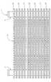
図1、2に示すように、本実施例1では車両用熱交換器1と、この車両用熱交換器1の前方側に配置された保護部材20が備えられている。
図3に示すように、車両用熱交換器1は、過給機付きエンジンにおいて、過給の効果を十分に引き出すために、圧縮した吸入空気を車両走行風またはファンの強制風で冷却する所謂空冷式インタークーラであって、コア部2と、吸入ポート3と、排出ポート4が備えられている。Example 1 will be described below.
The vehicle front-rear direction and the vehicle width direction will be described as the front-rear direction and the left-right direction.
1 is an overall front view showing a protective member structure of a heat exchanger for a vehicle according to a first embodiment of the present invention, FIG. 2 is a right side view thereof (the louver is omitted), and FIG. 3 is a heat exchanger for a vehicle according to the first embodiment. FIG. 4 is a diagram for explaining the tube of the first embodiment, FIG. 5 is a diagram for explaining the inner fin of the first embodiment, and FIG. 6 is a diagram for explaining the embossed portion of the first embodiment. .
7 is a side sectional view for explaining the inside of the vehicle heat exchanger of the first embodiment (the inner fin is omitted), FIG. 8 is a front view of the protective member of the first embodiment, and FIG. 9 is a rear view of the same. 10 is a right side view of the same, FIG. 11 is a cross-sectional view taken along the line S11-S11 of FIG. 8, illustrating a cross-sectional shape of the protection portion, and FIG.
As shown in FIGS. 1 and 2, the first embodiment includes a vehicle heat exchanger 1 and a
As shown in FIG. 3, the vehicle heat exchanger 1 is a so-called so-called cooler that cools the compressed intake air with the vehicle wind or the forced air of the fan in the engine with a supercharger in order to sufficiently bring out the supercharging effect. An air-cooled intercooler, which includes a
コア部2は、交互に配置された複数のチューブ5とアウターフィン6で構成され、図4に示すように、各チューブ5は最中状に重ねられる皿状の一対のシェル7,8と、この一対のシェル7,8の間に介装されるインナーフィン9で構成されている。
両シェル7,8のうち、シェル7の長手方向両端部には上方に開口する環状突起部7aが形成され、シェル8の長手方向両端部には下方に突出する円筒状の環状突起部8aがそれぞれ形成されている。The
Of the
インナーフィン9は、図5に示すような複数の柱部9aがチューブ5の長手方向と平行になるように配置された所謂オフセットフィンが採用される他、図4に示すようにシェル7,8の各環状突起部7a,8aと同軸上に開口部9bが形成されている。なお、インナーフィン9はオフセットフィンに限らず、波状のフィンでも良い。
また、図6に示すように、シェル7,8の環状突起部7a,8aに近接した位置には内側へ半円球状に窪んだエンボス部10が前後方向に離間して形成されると共に、これら両シェル7,8が重ねられた際にインナーフィン9が各エンボス部10により押圧された状態で位置決めされるようになっている。
さらに、図4に示すように、チューブ5におけるシェル7の環状突起部7aの外径W1は、シェル8の環状突起部8aの内径W2よりも小さく形成されており、これによって、図7に示すように、波状のアウターフィン6を介在させた状態で隣り合うチューブ5の環状突起部8aと環状突起部7aを嵌合させて複数積層することによりコア部2が形成されている。The
Further, as shown in FIG. 6, embossed
Further, as shown in FIG. 4, the outer diameter W1 of the
また、コア部2の最外端のチューブ5aの両端部の環状突起部7aには、円筒状の吸入ポート3と排出ポート4が挿入された状態で設けられる一方、コア部2の最外端のチューブ5bの両端部の環状突起部8aは省略されて塞がれた状態となっている。 In addition, the
従って、コア部2の一方側には、各チューブ5の一端側に連通し、且つ、吸入ポート3に連通する入口通路R1が形成され、コア部2の他方側には、各チューブ5の他端側に連通し、且つ、排出ポート4に連通する出口通路R2が形成されている。 Accordingly, an inlet passage R1 that communicates with one end of each
その他、本実施例1のアウターフィン6には波の頂部と谷部との間に複数のルーバ6a(図12参照)が形成されているが、この限りでない。 In addition, although the plurality of
また、本実施例1の車両用熱交換器1を構成する全ての構成部材はアルミ製であり、各構成部材が接合する接合部のうち、少なくとも一方側にはろう材から成るクラッド層(ブレージングシート)が設けられ、これらは予め仮組みされた状態で図外の加熱炉に搬送されて熱処理されることにより各接合部が一体的にろう付け固定されている。
なお、車両用熱交換器1の詳細な部位の形状、形成数、形成位置等については適宜設計変更可能である。In addition, all the constituent members constituting the vehicle heat exchanger 1 of the first embodiment are made of aluminum, and at least one side of the joint portion to which each constituent member is joined is a clad layer (brazing brazing material). Sheets) are provided, and these are transported to a heating furnace (not shown) in a pre-assembled state and heat-treated, whereby each joint is integrally brazed and fixed.
In addition, about the shape of the detailed site | part of the heat exchanger 1 for vehicles, the number of formation, a formation position, etc., a design change is possible suitably.
図8〜10に示すように、保護部材20は車両用熱交換器1のコア部2の長手方向の長さと同じ長さを有する複数の保護部21と、各保護部21の両端部同士を上下方向に結合する結合部22,23を備えて樹脂で一体的に形成されている。 As shown in FIGS. 8 to 10, the
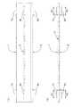
図2に示すように、各保護部21は車両用熱交換器1のコア部2の各チューブ5にそれぞれ対応した位置に設けられる他、図11に示すように、車両前方側に先細りした頂点21a部分を有する三角形断面形状に形成され、これによって隣接する保護部21同士における後端部21b同士間の開口幅W3が前端部21a同士間の開口幅W4よりも小さくなっている。
また、各保護部21の前後方向の寸法H、後面21dの上下方向の寸法W、頂点21aの角度αは適宜設定できるが、少なくとも上記寸法Wは車両用熱交換器2のチューブ5の上下方向の寸法以上の長さとなっている。As shown in FIG. 2, each
Moreover, although the dimension H of the front-back direction of each
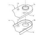
さらに、図9、10に示すように、結合部22,23の後面には後方へ円柱状に突出した固定部24が複数(本実施例では3カ所)形成されると共に、各固定部24の先端には上下方向に突出した円柱状のピン24a,24bが形成されている。 Further, as shown in FIGS. 9 and 10, a plurality of fixing portions 24 (three in this embodiment) are formed on the rear surfaces of the connecting
そして、各固定部24のピン24a,24bが車両用熱交換器2のそれぞれ対応するシェル7,8のエンボス部10に嵌合されることにより、車両用熱交換器1のコア部2の前方側に保護部材20が固定されている(図2参照)。
従って、各エンボス部10の内側でインナーフィン9を押圧して位置決めできると同時に、各エンボス部10の外側に固定部24のそれぞれ対応するピン24a,24bを嵌合させて固定できるようになっている。
また、この際、保護部材20の各保護部21がそれぞれ対応するチューブ5を覆う他、隣接する保護部21の後端部21b同士間にそれぞれ対応するアウターフィン6が配置されることとなる。Then, the
Accordingly, the
At this time, each of the
なお、本実施例1では車両用熱交換器1の各チューブ5と保護部材20との間には僅かな隙間W5(図12に参照)が形成されているが、これら両者は当接させても良い。 In the first embodiment, a slight gap W5 (see FIG. 12) is formed between each
次に、作用を説明する。
このように構成されたインタークーラは、図7に示すように、図外の過給機で圧縮された160℃前後の吸入空気(波線矢印で図示)が、吸入ポート3から入口通路R1に流入し、各チューブ5内を流通して出口通路R2に流入する間に、アウターフィン6を介して車両走行風または図外のファンによる強制風と熱交換して40℃前後まで冷却された後、排出ポート4から排出されてエンジンへ流入する。Next, the operation will be described.
In the intercooler configured as described above, as shown in FIG. 7, intake air of about 160 ° C. (illustrated by a wavy arrow) compressed by a supercharger (not shown) flows from the
この際、図12に示すように、上記車両走行風または図外のファンによる強制風Zは、各保護部21の頂点21aから上下方向に分かれて各傾斜部21dに沿ってそれぞれ対応するアウターフィン6へスムーズに進入する。 At this time, as shown in FIG. 12, the vehicle running wind or the forced wind Z generated by a fan not shown in the drawing is separated from the
従って、各保護部21は上記風Zをアウターフィン6へスムーズに導く導風機能を果たすことができる。 Therefore, each
また、前方からコア部2へ飛んできた飛び石等の攻撃物を保護部21で保護でき、チューブ5の破損・亀裂を防止できる。
この際、斜め前方から所定の角度α1で攻撃物Xがコア部2へ向かって飛んできた場合にも保護部5でコア部2、特にコア部2のチューブ5を確実に保護できる。
また、上記攻撃物Xが角度α1よりも小さい角度、つまり、水平方向に近い角度でコア部2へ飛んできた場合は、各保護部21同士間を通過しようとするが、前述したように、隣接する保護部21同士における後端部21b同士間の開口幅W3が前端21c同士間の開口幅W4よりも小さくなっているため、開口幅W3よりも大きな攻撃物が保護部21同士間を通過する虞がなく、コア部2の損傷を最小限に留めることができる。
また、例え開口幅W3よりも小さい攻撃物であっても該攻撃物はアウターフィン6に衝突するため、チューブ5が破損する虞がない。Further, an attacking object such as a stepping stone flying from the front to the
At this time, even when the attack object X flies toward the
In addition, when the attack object X flies to the
Further, even if the attacking object is smaller than the opening width W3, the attacking object collides with the
次に、効果を説明する。
以上、説明したように、本実施例1の車両用熱交換器の保護部材構造にあっては、交互に配置された複数のチューブ5とアウターフィン6でコア部2が構成されると共に、このコア部2の前面に保護部材20が設けられた車両用熱交換器1の保護部材構造において、保護部材20が、コア部2の各チューブ5の前方側を覆った状態で該チューブ5の長手方向に延在し、且つ、車両斜め前方からコア部2へ向かう攻撃物Xと該コア部2との衝突を防止する保護部21を備えるため、各チューブ5を確実に保護できると同時に車両斜め前方からコア部2へ向かう攻撃物Xとコア部2の衝突を防止できる。Next, the effect will be described.
As described above, in the protection member structure for a vehicle heat exchanger according to the first embodiment, the
また、隣接する保護部21同士における後端部21b同士間の開口幅W3が前端部21a同士間の開口幅W4よりも小さくなるように各保護部21の断面形状を形成したため、導風効果を得ることができると共に、開口幅W3よりも大きな攻撃物の保護部21同士間への通過を防止できる。 Moreover, since the cross-sectional shape of each
また、各保護部21の断面形状を車両前方側に先細りした略三角形断面形状に形成したため、上記風Zを効率よく導風するのに適した形状の保護部21となる。 Moreover, since the cross-sectional shape of each
また、車両用熱交換器1の各チューブ5の内部にインナーフィン9を介装すると共に、このインナーフィン9を各チューブ5に設けられたエンボス部10によって位置決めし、保護部材20にエンボス部10と嵌合する固定部24を設けて該保護部材20と車両用熱交換器1を固定したため、エンボス部10をインナーフィン9の位置決めと、保護部材20の固定の両方に兼用できる。 In addition, an
以下、実施例2を説明する。
本実施例2において実施例1と同一形状の構成部材については同じ符号を付してその説明は省略し、相違点のみ詳述する。Example 2 will be described below.
In the second embodiment, constituent members having the same shape as those in the first embodiment are denoted by the same reference numerals, description thereof is omitted, and only differences are described in detail.
図13は本実施例2の保護部の断面形状を説明する図である。 FIG. 13 is a diagram for explaining the cross-sectional shape of the protective portion of the second embodiment.
図13に示すように、本実施例2の車両用熱交換器の保護部材構造では、各保護部30が前方側に円弧形状を有する略半円形断面形状に形成されている点が実施例と異なる。 As shown in FIG. 13, in the protection member structure for a vehicle heat exchanger according to the second embodiment, each
従って、実施例1と同様の効果を得ることができる他、保護部30に必要な材料を削減して軽量化できる上、前方側に尖った部位がないため、攻撃物が保護部30に刺さって付着する虞がないという利点を有する。 Therefore, in addition to obtaining the same effect as that of the first embodiment, the material required for the
以上、本実施例を説明してきたが、本発明は上述の実施例に限られるものではなく、本発明の要旨を逸脱しない範囲の設計変更等があっても、本発明に含まれる。
例えば、車両用熱交換器はインタークーラに限らず、ラジエータ、コンデンサ、ラジエータとコンデンサが一体的に固設された一体型熱交換器、オイルクーラ等の一般的な全ての車両用熱交換器に適用可能である。
また、保護部の断面形状は略三角形断面形状や略半円形状に限らず、適宜設定できる。Although the present embodiment has been described above, the present invention is not limited to the above-described embodiment, and design changes and the like within the scope not departing from the gist of the present invention are included in the present invention.
For example, a vehicle heat exchanger is not limited to an intercooler, but can be applied to all general vehicle heat exchangers such as a radiator, a condenser, an integrated heat exchanger in which a radiator and a condenser are integrally fixed, and an oil cooler. Applicable.
Moreover, the cross-sectional shape of the protection part is not limited to a substantially triangular cross-sectional shape or a substantially semicircular shape, and can be set as appropriate.
R1 入口通路
R2 出口通路
1 車両用熱交換器
2 コア部
3 吸入ポート
4 排出ポート
5、5a、5b チューブ
6 アウターフィン
6a ルーバ
7、8 シェル
7a、8a 環状突起部
9 インナーフィン
9a 柱部
9b 開口部
10 ボス部
20 保護部材
21、30 保護部
21a 頂点
21b 後端部
21c 前端部
21d 後面
22、23 結合部
24 固定部
24a、24b ピンR1 Inlet passage R2 Outlet passage 1
Claims (5)
Translated fromJapanese前記保護部材が、コア部の各チューブの前方側を覆った状態で該チューブの長手方向に延在し、且つ、車両斜め前方からコア部へ向かう攻撃物と該コア部との衝突を防止する保護部を備えることを特徴とする車両用熱交換器の保護部材構造。In the protective member structure of the vehicle heat exchanger in which the core portion is configured by a plurality of alternately arranged tubes and fins, and a protective member is provided on the front surface of the core portion,
The protective member covers the front side of each tube of the core portion, extends in the longitudinal direction of the tube, and prevents collision between the attacking object heading from the diagonally front of the vehicle toward the core portion and the core portion. A protection member structure for a heat exchanger for a vehicle, comprising a protection part.
前記隣接する保護部同士における後端部同士間の開口幅が前端部同士間の開口幅よりも小さくなるように各保護部の断面形状を形成したことを特徴とする車両用熱交換器の保護部材構造。In the protection member structure of the heat exchanger for vehicles according to claim 1,
The protection of a vehicle heat exchanger characterized in that the cross-sectional shape of each protection portion is formed such that the opening width between the rear end portions of the adjacent protection portions is smaller than the opening width between the front end portions. Member structure.
前記各保護部の断面形状を車両前方側に先細りした略三角形断面形状に形成したことを特徴とする車両用熱交換器の保護部材構造。In the protection member structure of the heat exchanger for vehicles according to claim 1 or 2,
A protection member structure for a heat exchanger for a vehicle, wherein the cross-sectional shape of each of the protection portions is formed into a substantially triangular cross-sectional shape that tapers toward the vehicle front side.
前記各保護部の断面形状を車両前方側に円弧形状を有する略半円形断面形状に形成したことを特徴とする車両用熱交換器の保護部材構造。In the protection member structure of the heat exchanger for vehicles according to claim 1 or 2,
A protection member structure for a heat exchanger for a vehicle, wherein a cross-sectional shape of each of the protection portions is formed into a substantially semicircular cross-sectional shape having an arc shape on the front side of the vehicle.
前記車両用熱交換器の各チューブの内部にインナーフィンを介装すると共に、このインナーフィンを各チューブに設けられたエンボス部によって位置決めし、
前記保護部材に前記エンボス部と嵌合する固定部を設けて該保護部材と車両用熱交換器を固定したことを特徴とする車両用熱交換器の保護部材構造。In the protection member structure of the heat exchanger for vehicles in any one of Claims 1-4,
While interposing an inner fin inside each tube of the vehicle heat exchanger, the inner fin is positioned by an embossed portion provided in each tube,
A protective member structure for a heat exchanger for a vehicle, wherein the protective member is provided with a fixing portion that fits with the embossed portion to fix the protective member and the vehicle heat exchanger.
Priority Applications (4)
| Application Number | Priority Date | Filing Date | Title |
|---|---|---|---|
| JP2006120316AJP2007291937A (en) | 2006-04-25 | 2006-04-25 | Protective member structure of heat exchanger for vehicles |
| US12/294,356US20090126916A1 (en) | 2006-04-25 | 2007-04-02 | Protecting structure of heat exchanger for motor vehicle |
| EP07740812AEP2011976A1 (en) | 2006-04-25 | 2007-04-02 | Structure of protective member for vehicle heat exchanger |
| PCT/JP2007/057376WO2007125727A1 (en) | 2006-04-25 | 2007-04-02 | Structure of protective member for vehicle heat exchanger |
Applications Claiming Priority (1)
| Application Number | Priority Date | Filing Date | Title |
|---|---|---|---|
| JP2006120316AJP2007291937A (en) | 2006-04-25 | 2006-04-25 | Protective member structure of heat exchanger for vehicles |
Publications (1)
| Publication Number | Publication Date |
|---|---|
| JP2007291937Atrue JP2007291937A (en) | 2007-11-08 |
Family
ID=38655262
Family Applications (1)
| Application Number | Title | Priority Date | Filing Date |
|---|---|---|---|
| JP2006120316AWithdrawnJP2007291937A (en) | 2006-04-25 | 2006-04-25 | Protective member structure of heat exchanger for vehicles |
Country Status (4)
| Country | Link |
|---|---|
| US (1) | US20090126916A1 (en) |
| EP (1) | EP2011976A1 (en) |
| JP (1) | JP2007291937A (en) |
| WO (1) | WO2007125727A1 (en) |
Cited By (4)
| Publication number | Priority date | Publication date | Assignee | Title |
|---|---|---|---|---|
| JP2015007519A (en)* | 2013-06-26 | 2015-01-15 | サンデン株式会社 | Cold storage vessel |
| JP2015059732A (en)* | 2013-09-20 | 2015-03-30 | 株式会社デンソー | Heat exchanger |
| JP2015087045A (en)* | 2013-10-29 | 2015-05-07 | 株式会社デンソー | Heat exchanger |
| KR20160118572A (en)* | 2015-04-02 | 2016-10-12 | 한온시스템 주식회사 | Protective device of condenser for vehicle |
Families Citing this family (11)
| Publication number | Priority date | Publication date | Assignee | Title |
|---|---|---|---|---|
| WO2011106063A2 (en)* | 2010-02-26 | 2011-09-01 | Carrier Corporation | Refrigerated case |
| CN103229014B (en)* | 2010-05-28 | 2015-11-25 | 丰田自动车株式会社 | Heat exchanger and manufacture method thereof |
| CA2914453A1 (en)* | 2013-06-27 | 2014-12-31 | Dana Canada Corporation | Fluid channels having performance enhancement features and devices incorporating same |
| FR3035955B1 (en)* | 2015-05-06 | 2019-04-19 | Valeo Systemes Thermiques | HEAT EXCHANGER HAVING A PROTECTION DEVICE |
| US10222130B2 (en)* | 2016-08-08 | 2019-03-05 | Caterpillar Inc. | Work machine heat exchanger |
| FR3060106B1 (en)* | 2016-12-12 | 2019-05-17 | Valeo Systemes Thermiques | HEAT EXCHANGE DEVICE HAVING A PROTECTION DEVICE |
| FR3073453B1 (en)* | 2017-05-02 | 2021-03-05 | Valeo Systemes Thermiques | HEAT EXCHANGER PROTECTION DEVICE |
| FR3079453B1 (en)* | 2017-05-02 | 2021-03-05 | Valeo Systemes Thermiques | HEAT EXCHANGE DEVICE INCLUDING A PROTECTION NET |
| DE102017221083A1 (en)* | 2017-11-24 | 2019-05-29 | Mahle International Gmbh | Heat exchanger for a motor vehicle |
| FR3088711B1 (en)* | 2018-11-16 | 2021-07-30 | Valeo Systemes Thermiques | MOTOR VEHICLE HEAT EXCHANGER |
| EP3943865A1 (en)* | 2020-07-23 | 2022-01-26 | Valeo Autosystemy SP. Z.O.O. | A heat exchanger assembly |
Family Cites Families (8)
| Publication number | Priority date | Publication date | Assignee | Title |
|---|---|---|---|---|
| JPH0293299A (en)* | 1988-09-30 | 1990-04-04 | Komatsu Ltd | Variable wind direction heat exchanger |
| AU2114299A (en)* | 1998-01-14 | 1999-08-02 | Conway-Stuart Medical, Inc. | Electrosurgical device for sphincter treatment |
| JP3983898B2 (en) | 1998-08-10 | 2007-09-26 | カルソニックカンセイ株式会社 | Condenser for automotive air conditioner |
| US20030094260A1 (en)* | 2001-11-19 | 2003-05-22 | Whitlow Gregory Alan | Heat exchanger tube with stone protection appendage |
| JP2003279278A (en)* | 2002-01-15 | 2003-10-02 | Denso Corp | Heat exchanger |
| JP3879614B2 (en)* | 2002-07-25 | 2007-02-14 | 株式会社デンソー | Heat exchanger |
| JP2004263997A (en)* | 2003-03-04 | 2004-09-24 | Calsonic Kansei Corp | Evaporator |
| JP2006064345A (en)* | 2004-08-30 | 2006-03-09 | T Rad Co Ltd | Heat transfer fins |
- 2006
- 2006-04-25JPJP2006120316Apatent/JP2007291937A/ennot_activeWithdrawn
- 2007
- 2007-04-02WOPCT/JP2007/057376patent/WO2007125727A1/enactiveApplication Filing
- 2007-04-02USUS12/294,356patent/US20090126916A1/ennot_activeAbandoned
- 2007-04-02EPEP07740812Apatent/EP2011976A1/ennot_activeWithdrawn
Cited By (6)
| Publication number | Priority date | Publication date | Assignee | Title |
|---|---|---|---|---|
| JP2015007519A (en)* | 2013-06-26 | 2015-01-15 | サンデン株式会社 | Cold storage vessel |
| US9803933B2 (en) | 2013-06-26 | 2017-10-31 | Sanden Holdings Corporation | Cold storage medium container |
| JP2015059732A (en)* | 2013-09-20 | 2015-03-30 | 株式会社デンソー | Heat exchanger |
| JP2015087045A (en)* | 2013-10-29 | 2015-05-07 | 株式会社デンソー | Heat exchanger |
| KR20160118572A (en)* | 2015-04-02 | 2016-10-12 | 한온시스템 주식회사 | Protective device of condenser for vehicle |
| KR102141872B1 (en) | 2015-04-02 | 2020-08-07 | 한온시스템 주식회사 | Protective device of condenser for vehicle |
Also Published As
| Publication number | Publication date |
|---|---|
| EP2011976A1 (en) | 2009-01-07 |
| US20090126916A1 (en) | 2009-05-21 |
| WO2007125727A1 (en) | 2007-11-08 |
Similar Documents
| Publication | Publication Date | Title |
|---|---|---|
| JP2007291937A (en) | Protective member structure of heat exchanger for vehicles | |
| JP5473656B2 (en) | Protection device for vehicle heat exchanger | |
| US8915292B2 (en) | Exhaust gas heat exchanger and method of operating the same | |
| JP5803768B2 (en) | Heat exchanger fins and heat exchangers | |
| ES2394406B1 (en) | HEAT EXCHANGER FOR GASES, ESPECIALLY EXHAUST GASES FROM AN ENGINE. | |
| WO2014013725A1 (en) | Heat exchanger | |
| US20020129929A1 (en) | Core structure of integral heat-exchanger | |
| WO2015059890A1 (en) | Cooling system | |
| JP2005221127A (en) | Core part structure of heat exchanger | |
| JP2008069756A (en) | Cooling device for vehicle | |
| JP2006336890A (en) | Intercooler | |
| JP2006284107A (en) | Heat exchanger | |
| JP6577282B2 (en) | Heat exchanger | |
| JP4173959B2 (en) | Integrated heat exchanger core structure | |
| JP6051641B2 (en) | Intercooler for vehicle | |
| JP2007216748A (en) | Air guide for vehicle | |
| JP2006207966A (en) | Heat exchanger | |
| JP2017101842A (en) | Heat exchanger | |
| US20090114366A1 (en) | Heat exchanger for vehicle | |
| CN113085473B (en) | Layout structure of refrigerant piping near heat accumulator in vehicle | |
| JP6079562B2 (en) | Heat exchanger | |
| JP2008309377A (en) | Tank structure of radiator | |
| JP2010032074A (en) | Heat exchanger | |
| JP6787301B2 (en) | Heat exchanger tube and heat exchanger | |
| JP2009074768A (en) | Heat exchanger |
Legal Events
| Date | Code | Title | Description |
|---|---|---|---|
| A621 | Written request for application examination | Free format text:JAPANESE INTERMEDIATE CODE: A621 Effective date:20090223 | |
| A761 | Written withdrawal of application | Free format text:JAPANESE INTERMEDIATE CODE: A761 Effective date:20100223 |