JP2007289715A - Ultrasonic diagnostic and therapeutic system - Google Patents
Ultrasonic diagnostic and therapeutic systemDownload PDFInfo
- Publication number
- JP2007289715A JP2007289715AJP2007122726AJP2007122726AJP2007289715AJP 2007289715 AJP2007289715 AJP 2007289715AJP 2007122726 AJP2007122726 AJP 2007122726AJP 2007122726 AJP2007122726 AJP 2007122726AJP 2007289715 AJP2007289715 AJP 2007289715A
- Authority
- JP
- Japan
- Prior art keywords
- ultrasonic
- therapeutic
- treatment
- observation
- transducer
- Prior art date
- Legal status (The legal status is an assumption and is not a legal conclusion. Google has not performed a legal analysis and makes no representation as to the accuracy of the status listed.)
- Pending
Links
- 230000001225therapeutic effectEffects0.000titleclaimsabstractdescription137
- 239000000523sampleSubstances0.000claimsabstractdescription112
- 238000011282treatmentMethods0.000claimsdescription156
- 238000003780insertionMethods0.000claimsdescription45
- 230000037431insertionEffects0.000claimsdescription45
- 238000002604ultrasonographyMethods0.000claimsdescription22
- 238000006073displacement reactionMethods0.000claimsdescription4
- 238000005452bendingMethods0.000abstractdescription22
- 238000009210therapy by ultrasoundMethods0.000description34
- 238000010586diagramMethods0.000description20
- 230000033001locomotionEffects0.000description19
- 238000001514detection methodMethods0.000description13
- 230000003287optical effectEffects0.000description13
- 238000002560therapeutic procedureMethods0.000description13
- 230000005540biological transmissionEffects0.000description11
- 210000001519tissueAnatomy0.000description11
- 210000000683abdominal cavityAnatomy0.000description10
- 230000000694effectsEffects0.000description10
- 238000007912intraperitoneal administrationMethods0.000description10
- 238000005286illuminationMethods0.000description9
- WABPQHHGFIMREM-UHFFFAOYSA-Nlead(0)Chemical compound[Pb]WABPQHHGFIMREM-UHFFFAOYSA-N0.000description9
- 238000003745diagnosisMethods0.000description8
- FAPWRFPIFSIZLT-UHFFFAOYSA-MSodium chlorideChemical compound[Na+].[Cl-]FAPWRFPIFSIZLT-UHFFFAOYSA-M0.000description7
- 210000001035gastrointestinal tractAnatomy0.000description7
- 239000004973liquid crystal related substanceSubstances0.000description7
- 239000011780sodium chlorideSubstances0.000description7
- 238000000034methodMethods0.000description6
- 238000006243chemical reactionMethods0.000description4
- 210000000056organAnatomy0.000description4
- 238000003384imaging methodMethods0.000description3
- 238000002347injectionMethods0.000description3
- 239000007924injectionSubstances0.000description3
- 230000001678irradiating effectEffects0.000description3
- 230000003902lesionEffects0.000description3
- 206010028980NeoplasmDiseases0.000description2
- VYPSYNLAJGMNEJ-UHFFFAOYSA-NSilicium dioxideChemical compoundO=[Si]=OVYPSYNLAJGMNEJ-UHFFFAOYSA-N0.000description2
- XUIMIQQOPSSXEZ-UHFFFAOYSA-NSiliconChemical compound[Si]XUIMIQQOPSSXEZ-UHFFFAOYSA-N0.000description2
- 230000007850degenerationEffects0.000description2
- 210000003238esophagusAnatomy0.000description2
- 239000000945fillerSubstances0.000description2
- 230000001151other effectEffects0.000description2
- 102000004169proteins and genesHuman genes0.000description2
- 108090000623proteins and genesProteins0.000description2
- 210000000664rectumAnatomy0.000description2
- 229910052710siliconInorganic materials0.000description2
- 239000010703siliconSubstances0.000description2
- 210000000115thoracic cavityAnatomy0.000description2
- 210000005239tubuleAnatomy0.000description2
- XLYOFNOQVPJJNP-UHFFFAOYSA-NwaterSubstancesOXLYOFNOQVPJJNP-UHFFFAOYSA-N0.000description2
- JOYRKODLDBILNP-UHFFFAOYSA-NEthyl urethaneChemical compoundCCOC(N)=OJOYRKODLDBILNP-UHFFFAOYSA-N0.000description1
- 206010051482ProstatomegalyDiseases0.000description1
- 229910052581Si3N4Inorganic materials0.000description1
- XAGFODPZIPBFFR-UHFFFAOYSA-NaluminiumChemical compound[Al]XAGFODPZIPBFFR-UHFFFAOYSA-N0.000description1
- 229910052782aluminiumInorganic materials0.000description1
- 201000011510cancerDiseases0.000description1
- 230000005674electromagnetic inductionEffects0.000description1
- 230000007274generation of a signal involved in cell-cell signalingEffects0.000description1
- 210000002429large intestineAnatomy0.000description1
- 210000003750lower gastrointestinal tractAnatomy0.000description1
- 230000017074necrotic cell deathEffects0.000description1
- 230000005855radiationEffects0.000description1
- 230000002040relaxant effectEffects0.000description1
- 239000004065semiconductorSubstances0.000description1
- 235000012239silicon dioxideNutrition0.000description1
- 239000000377silicon dioxideSubstances0.000description1
- HQVNEWCFYHHQES-UHFFFAOYSA-Nsilicon nitrideChemical compoundN12[Si]34N5[Si]62N3[Si]51N64HQVNEWCFYHHQES-UHFFFAOYSA-N0.000description1
- 239000004575stoneSubstances0.000description1
- 239000000126substanceSubstances0.000description1
- 239000000758substrateSubstances0.000description1
- 238000000015thermotherapyMethods0.000description1
- 210000004888thoracic abdominal cavityAnatomy0.000description1
- 210000002438upper gastrointestinal tractAnatomy0.000description1
Images


Landscapes
- Surgical Instruments (AREA)
- Ultra Sonic Daignosis Equipment (AREA)
Abstract
Description
Translated fromJapanese本発明は、体腔内に挿入して超音波診断と集束超音波による超音波治療とを行う超音波プローブを有する超音波診断治療システムに関する。 The present invention relates to an ultrasonic diagnostic treatment system having an ultrasonic probe that is inserted into a body cavity and performs ultrasonic diagnosis and ultrasonic treatment using focused ultrasound.
近年、超音波振動子から生体組織内に超音波パルスを繰り返し送信し、この生体組織から反射される超音波パルスのエコーを同一、或は、別体に設けた超音波振動子で受信して、この超音波パルスを送受信する方向を徐々にずらすことによって、生体内の複数の方向から収集した情報を可視像の超音波診断画像として表示する超音波診断装置が種々提案されている。 In recent years, an ultrasonic pulse is repeatedly transmitted from an ultrasonic transducer into a living tissue, and an echo of the ultrasonic pulse reflected from the living tissue is received by an ultrasonic transducer provided on the same or separate body. Various ultrasonic diagnostic apparatuses have been proposed in which information collected from a plurality of directions in a living body is displayed as a visible ultrasonic diagnostic image by gradually shifting the direction in which the ultrasonic pulse is transmitted and received.
これらは、体外式超音波プローブによるものが一般的であるが、内視鏡に組み合わせたものや、細径の超音波プローブ、体腔内に挿入する体腔内超音波プローブなどの体内式超音波プローブも広く用いられている。 These are generally based on an external ultrasound probe, but are combined with an endoscope, an ultrasound probe with a small diameter, or an intracorporeal ultrasound probe to be inserted into a body cavity. Is also widely used.
一方、結石破砕装置や超音波温熱治療装置など、集束した超音波により種々の治療を行う超音波治療装置も種々提案されている。これらの超音波による治療装置の中には、集束した高強度の超音波により癌細胞などの生体組織を瞬時に高温焼灼して治療する超音波高温治療装置があった。 On the other hand, various ultrasonic treatment apparatuses that perform various treatments using focused ultrasonic waves, such as a stone crushing apparatus and an ultrasonic thermotherapy apparatus, have been proposed. Among these ultrasonic treatment devices, there is an ultrasonic high-temperature treatment device that instantaneously cauterizes a living tissue such as cancer cells with focused high-intensity ultrasonic waves.
この超音波高温治療装置は、高強度の集束超音波を得るため、大きな開口の超音波振動子を有する体外アプリケータから目的部位に集束させるもののほかに、例えばPCT WO93/16641号公報に示されるように、比較的小型の超音波振動子を内蔵し、直腸に挿入して肥大した前立腺を治療する体腔内プローブが知られている。 This ultrasonic high-temperature treatment apparatus is shown in, for example, PCT WO 93/16641, in addition to focusing on an objective site from an extracorporeal applicator having an ultrasonic transducer with a large aperture in order to obtain high-intensity focused ultrasound. As described above, an intracavity probe is known that incorporates a relatively small ultrasonic transducer and treats an enlarged prostate by inserting it into the rectum.
また、前記PCT WO93/16641号公報に示される超音波治療装置には深部処置部位(焦点)の位置決めを行うための位置決め手段として例えば、超音波断層像を得る超音波診断装置などが組み合わされている。従って、体外アプリケータや体腔内プローブに焦点位置決め用の診断用超音波振動子が内蔵されているものが種々提案されている。 Further, the ultrasonic therapy apparatus disclosed in the PCT WO 93/16641 is combined with, for example, an ultrasonic diagnostic apparatus for obtaining an ultrasonic tomographic image as positioning means for positioning a deep treatment site (focal point). Yes. Accordingly, various proposals have been made in which an extracorporeal applicator or an intracavity probe incorporates a diagnostic ultrasound transducer for focus positioning.
しかしながら、PCT WO93/16641号公報に示される体腔内プローブではプローブ本体の外径寸法が太径であると共に、硬性であり、診断用及び治療用超音波を放射するプローブ先端部を自由に湾曲させることができなかった。このため、体腔内プローブの適用が直腸や大腸など、極めて限られた部位となり、上部消化管,下部消化管,或は、腹腔などに挿入するのに適さなかった。 However, in the body cavity probe shown in PCT WO93 / 16641, the outer diameter of the probe body is large and rigid, and the tip of the probe that emits diagnostic and therapeutic ultrasound is freely curved. I couldn't. For this reason, the application of the body cavity probe has become a very limited site such as the rectum or the large intestine, and is not suitable for insertion into the upper digestive tract, the lower digestive tract, or the abdominal cavity.
また、プローブ先端部を自由に湾曲させることができないため及び、治療用超音波トランスデューサの照射方向を変えるための駆動性が十分でないため、目的とする処置部位へ超音波エネルギーを的確に照射し難いという問題があった。 In addition, since the probe tip cannot be bent freely and the driveability for changing the irradiation direction of the therapeutic ultrasonic transducer is not sufficient, it is difficult to accurately irradiate the target treatment site with ultrasonic energy. There was a problem.
本発明は前記事情に鑑みてなされたものであり、上部消化管、下部消化管、胸腔、腹腔や脳室などの体腔内に挿入して、処置部位の所望の位置に容易、且つ、的確に高密度の超音波エネルギーを照射することができる超音波プローブを有する超音波診断治療システムを提供することを目的としている。 The present invention has been made in view of the above circumstances, and can be inserted into a body cavity such as the upper digestive tract, the lower digestive tract, the thoracic cavity, the abdominal cavity or the ventricle, and easily and accurately at a desired position of the treatment site. An object of the present invention is to provide an ultrasonic diagnostic treatment system having an ultrasonic probe capable of irradiating high-density ultrasonic energy.
本発明の超音波診断治療システムは、体腔内に挿入可能な挿入部を備えたプローブと、前記挿入部に設けられ、極座標的な超音波を出射し、前記体腔内の超音波画像を得るために、前記体腔内から反射される超音波エコーを受信する超音波観測手段と、前記挿入部に設けられ、収束するように超音波を出射可能な治療用超音波出射手段と、前記治療用超音波出射手段により収束位置および収束方向の少なくとも一方を可変する第2の可変手段と、前記治療用超音波出射手段からの収束した超音波を前記患部に対して出射するように前記第2の可変手段を制御する第2の制御手段と、前記プローブの先端部に設けられ、形状を変位することにより、前記治療用超音波出射手段から治療対象部位である患部までに超音波集束距離を変位せしめることにより、前記超音波観測手段により得られる観察領域を可変可能とする第1の可変手段と、患部を含む前記観察領域の超音波画像を得るように前記第1の可変手段の形状の変位を制御する第1の制御手段と、前記第1の制御手段の制御による前記第1の可変手段の変位によって前記超音波集束距離の調整終了後、前記治療用超音波出射手段からの収束した超音波が、前記超音波観測手段により観察される患部を含む観察領域に対して含まれるように、前記第2の制御手段を制御する第3の制御手段と、を備えることを特徴とする。 An ultrasonic diagnostic treatment system of the present invention is provided with a probe having an insertion part that can be inserted into a body cavity, and is provided in the insertion part to emit a polar coordinate ultrasonic wave to obtain an ultrasound image in the body cavity. In addition, an ultrasonic observation unit that receives an ultrasonic echo reflected from the body cavity, a therapeutic ultrasonic wave output unit that is provided in the insertion portion and can output an ultrasonic wave so as to converge, and the therapeutic ultrasonic wave A second variable means for varying at least one of a convergence position and a convergence direction by a sound wave emitting means; and the second variable so that the converged ultrasonic wave from the therapeutic ultrasonic wave emitting means is emitted to the affected area. A second control means for controlling the means, and a distal end portion of the probe, and by displacing the shape, the ultrasonic focusing distance is displaced from the therapeutic ultrasonic wave emitting means to the affected area which is a treatment target site. This To control the displacement of the shape of the first variable means so as to obtain an ultrasonic image of the observation area including the affected area, and a first variable means that makes the observation area obtained by the ultrasonic observation means variable. After the adjustment of the ultrasonic focusing distance due to the displacement of the first control means and the first variable means under the control of the first control means, the converged ultrasonic waves from the therapeutic ultrasonic wave emitting means are And third control means for controlling the second control means so as to be included in an observation region including an affected part observed by the ultrasonic observation means.
本発明によれば、上部消化管、下部消化管、胸腔、腹腔や脳室などの体腔内に挿入して、処置部位の所望の位置に容易、且つ、的確に高密度の超音波エネルギーを照射することができる超音波プローブを有する超音波診断治療システムを提供することができる。 According to the present invention, it is inserted into a body cavity such as the upper gastrointestinal tract, lower gastrointestinal tract, thoracic cavity, abdominal cavity or ventricle, and a desired position of the treatment site is easily and accurately irradiated with high-density ultrasonic energy. An ultrasonic diagnostic treatment system having an ultrasonic probe that can be provided can be provided.
以下、図面を参照して本発明の実施の形態を説明する。 Embodiments of the present invention will be described below with reference to the drawings.
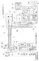
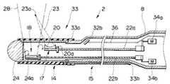
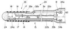
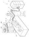
図1ないし図4は本発明の第1実施の形態に係り、図1は超音波診断治療システムの概略構成を示す全体図、図2は電子内視鏡的な光学観察手段を有する超音波プローブの斜視図、図3は超音波プローブの先端部の概略構成を示す断面図、図4は超音波プローブの作用を示す説明図である。 1 to 4 relate to a first embodiment of the present invention, FIG. 1 is an overall view showing a schematic configuration of an ultrasonic diagnostic treatment system, and FIG. 2 is an ultrasonic probe having an electronic endoscopic optical observation means. FIG. 3 is a cross-sectional view showing a schematic configuration of the distal end portion of the ultrasonic probe, and FIG. 4 is an explanatory view showing the operation of the ultrasonic probe.
図1に示すように第1実施の形態の超音波診断治療システム1は、例えば電子内視鏡的な構成を有する超音波プローブ2と、この超音波プローブ2に照明光を供給する光源装置3と、超音波プローブ2に内蔵された撮像手段に対する信号処理を行うカメラコントロールユニット(以下、CCUと略記)4と、超音波画像を生成する信号処理系5Aと治療のための信号を生成する治療用信号生成系5Bとを内蔵した超音波診断治療回路5と、CCU4の映像信号処理系(不図示)及び超音波信号処理系5Aの映像信号より内視鏡画像と超音波画像とを表示するカラーモニタ6などから構成されている。 As shown in FIG. 1, the ultrasonic
図1及び図2に示すように前記電子内視鏡的な構成の超音波プローブ2は、体腔内に挿入可能なように細管状になった挿入部7と、この挿入部7の後端に形成され、術者が把持し操作を行う操作部8と、この操作部8から延出されたユニバーサルケーブル9とを有している。このユニバーサルケーブル9の端部に設けた光源コネクタ10を介して光源装置3に着脱自在に接続することができるようになっている。 As shown in FIGS. 1 and 2, the
この光源コネクタ10には信号ケーブル11の一端の信号コネクタ12aが接続される一方、この信号ケーブル11の他端側にはCCU4に接続されるCCUコネクタ12bと、超音波診断治療回路5に接続される超音波コネクタ12cとが設けられている。 A signal connector 12 a at one end of the signal cable 11 is connected to the
前記挿入部7は、硬質な先端部14と、湾曲自在な湾曲部15と、可撓性を有する可撓部16とが先端側から順次連接して形成されている。そして、この先端部14には後述する超音波治療手段17,超音波観測手段18,処置機能ガイド部19,光学的観察手段30,超音波集束点調整手段33などが配設されるようになっている。 The
光学的観察手段30は、ライトガイド31a及び照明窓のレンズ31bを経て照明光を出射する照明光出射手段と、この照明光で照明された対象組織側の光学像を結ぶ対物レンズ32a及びこの対物レンズ32aの焦点面に配置したCCD32bとを有する撮像手段とで構成されている。 The
前記ライトガイド31aは、挿入部内などを挿通して、光源コネクタ10を介して光源装置3に接続されるようになっており、ランプ34で発生した照明光をレンズでライトガイド31aの後端面に集光させてライトガイド31aの先端部側に伝送し、照明レンズ31bを透過して斜め前方を照らすようになっている。 The light guide 31a is inserted into the insertion portion or the like and is connected to the
この斜め前方に出射された照明光で照明される範囲は、対物レンズ32aによる観察範囲と略一致し、この対物レンズ32aによって、照明光で照明された観察部位の被写体像がCCD32bの撮像面に結像するようになっている。このCCD32bに結像した被写体像の電気信号は、信号線36によってCCU4内の映像信号処理系に伝達され、映像信号に変換されて、スーパインポーズ回路29を経てカラーモニタ6に内視鏡画像37として表示されるようになっている。 The range illuminated by the illumination light emitted obliquely forward substantially coincides with the observation range by the objective lens 32a, and the object image of the observation site illuminated by the illumination light is reflected on the imaging surface of the
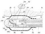
図3に示すように超音波を処置部に出射して超音波高温治療などを行うための超音波治療手段17は、例えば挿入軸方向に円弧状の凹面を形成し、一端を第1のフレキシブルシャフト22aに接続し、挿入軸方向に対して直角方向に回転自在な固定部材20aに一体的に固定したメカニカルラジアルスキャン型の治療用超音波振動子20である。この治療用振動子20は、操作部8に配設したモータ34aの回転力が第1のフレキシブルシャフト22aに伝達されることによって挿入軸方向に対して直角方向に回転するようになっている。そして、図1に示す挿入部内などを挿通するリード線21に接続された超音波診断治療回路5に設けた駆動電圧発生回路22で駆動信号を印加することにより、治療用超音波が凹面状部から指向性を有する治療用超音波ビームとなって破線(図3参照)に示すような出射範囲23で出射され、所定の距離の収束点23aに収束するようになっている。 As shown in FIG. 3, the ultrasonic treatment means 17 for emitting ultrasonic waves to the treatment section and performing ultrasonic high-temperature treatment or the like forms, for example, an arc-shaped concave surface in the insertion axis direction, and one end of the first flexible treatment means This is a mechanical radial scan type ultrasonic transducer for
この治療用超音波振動子20から出射される治療用超音波は、収束点23aで非常に高強度の超音波ビーム、つまり、音響的に高エネルギ密度になる。従って、収束点23a付近に例えば、腫瘍などの病変組織を位置させた状態で、治療用超音波振動子20に駆動信号を印加して、高密度の音響的エネルギを病変組織に照射することによって、病変組織を焼灼して治療処置が行えるようになっている。 The therapeutic ultrasonic wave emitted from the therapeutic
なお、この治療用超音波振動子20が挿入軸方向に対して直角方向に回転自在であることから、治療用超音波振動子20を挿入軸方向に対して直角方向に回転させることによって、治療用超音波振動子20の出射面を処置部に容易に対設させることができるので、後述する超音波集束点調整手段をも兼ねる構成となっている。 Since the therapeutic
また、超音波画像を得るための超音波観測手段18は、例えば平板状に構成され、一端を第2のフレキシブルシャフト22bに接続し、挿入軸方向に対して直角方向に回転自在な固定部材24aに一体的に固定したメカニカルラジアルスキャン型の観察用超音波振動子24である。この観察用超音波振動子24は、操作部8に配設したモータ34bの回転を第2のフレキシブルシャフト22bに伝達することによって挿入軸方向に対して直角方向に回転するようになっている。そして、図1に示す挿入部内などを挿通するリード線24を介して送信パルス発生回路26及び受信処理回路27を備えた信号処理系5Aに接続され、送信パルス発生回路26の送信パルスを印加することにより、観察用超音波振動子24から図中一点鎖線に示すように放射状の超音波観測領域28に超音波を対象組織側に送波し、対象組織側で反射した超音波を再び観察用超音波振動子24で受波し、電気信号に変換した後、受信処理回路27で信号処理され、超音波画像に対応する映像信号に変換した後、スーパインポーズ回路29を経てカラーモニタ6に入力して、内視鏡的画像37と共に超音波断層画像37′が表示されるようになっている。 The ultrasonic observation means 18 for obtaining an ultrasonic image is configured, for example, in a flat plate shape, one end connected to the second
さらに、前記観察用超音波振動子24及び治療用超音波振動子20を配設した超音波プローブ2の先端部14の外周には治療用超音波振動子20から出射される超音波を治療対象部位へ高エネルギ密度で照射することが可能なように治療用超音波振動子20から治療対象部位までの超音波集束距離を制御する超音波集束点調整手段33として、バルーン33aが設けられている。このバルーン33aは、手元側に設けた注入孔33bより音響伝達媒体としての生食水などを注入することによって膨張可能となっている。 Furthermore, ultrasonic waves emitted from the therapeutic
なお、湾曲部15は、多数の湾曲駒を互いに回動自在に連接して形成され、湾曲部15の一端側を先端部14に固定し、他端側を可撓部16に固定している。そして、操作部内のプーリ38に接続されたアングルワイヤ39をアングルノブ40の回動操作によって牽引・弛緩させることにより、湾曲部15をアングルワイヤ39が牽引される方向、すなわち上下左右の4方向、或は、上下ないし左右の2方向に湾曲するようにしている。このように、超音波プローブ2の湾曲部15の構成は通常の内視鏡に用いられる湾曲部と略同様の構成となっている。
また、前記操作部8の先端部付近には鉗子などの処置具を導入する導入口41が設けてあり、この導入口41は挿入部内に設けた処置具チャンネル42と連通し、先端部14に設けた処置機能ガイド部19の開口を鉗子出口42aとしている。この鉗子出口42aは、光学的観察手段30の至近位置に開口するように設けることによって、この鉗子出口42aから例えば処置具を突出させて生体に対して処置などを行う場合、鉗子出口42aから突出する処置具及び処置具による処置状況を容易に観察することができるようになっている。The bending
An
さらに、操作部8には符号45に示す送気・送水釦や、この送気・送水釦45に隣接して吸引釦46が設けられると共に、光学的観察手段30の撮像手段による内視鏡的画像のフリーズ、或は、表示切換え制御などをそれぞれ行う画像制御釦(又は画像制御スイッチ)47,48が設けられている。これら画像制御釦47,48から出力される信号は、CCU4及びコントローラ49に入力されるようになっている。このコントローラ49は、キーボード50及びフットスイッチ51に接続され、このキーボード50によって、超音波治療手段17から出射する超音波出射時間の設定や患者のカルテ情報などを入力することが可能となっている。そして、フットスイッチ51を操作することによって超音波治療手段17による治療開始及び停止を行えるようになっている。 Further, the
又、コントローラ49は、超音波診断治療回路5内の送信回路26などと接続され、超音波観測画像の超音波送信条件の変更や、受信した信号に対する信号処理の条件変更及び超音波治療の出力条件の変更などを行うことができるようになっている。 The
更に、コントローラ49は、CCU4とも接続され、キーボード50からCCU4を制御することができるようになっている。 Further, the
上述のように構成した超音波診断治療システム1の作用を説明する。
図4に示すように例えば、食道などの管腔臓器内61に、まず、超音波プローブ2の挿入部15を挿入していく。このとき、挿入部15に設けた湾曲部15を湾曲操作しながら光学観察手段30による光学像並びに超音波観察手段18による超音波診断画像を元に先端部14を治療処置する処置部62の近傍に配置させる。このとき、モータ34bで観察用超音波振動子24を回転させてラジアル走査を行って、挿入軸方向に対して直角方向の位置制御を行い、処置部62の超音波が像をモニタ6に映し出すと共に、モータ34aで治療用超音波振動子20を所望の量だけ回転させて、治療用超音波振動子20の出射面の挿入軸方向に対して直角方向の位置制御を行う。The operation of the ultrasonic
As shown in FIG. 4, for example, the
次に、管腔臓器内61の病変部近傍に配置した先端部内に設けた治療用超音波振動子20の出射面に対して処置部62の深さ方向の位置が治療用超音波の集束点となるように、先端部外周に配設したバルーン33aに注入孔33bより生食水を注入してバルーン33aを徐々に膨張させ、処置部62が治療用超音波振動子20の超音波集束点の位置調整を行う。 Next, the position of the
次いで、コントローラ49,キーボード50により処置部62に出射される超音波の出力条件を確認後、モニタ6の内視鏡画像37及び超音波画像37′を観察しながら、フットスイッチ51を操作して治療用超音波振動子20から処置部62に向かって治療用超音波を出射する。 Next, after confirming the output conditions of the ultrasonic waves emitted to the
すると、集束点に位置する処置部62に高エネルギ密度の治療用超音波が集束し、処置部62が急激に温度上昇して焼灼される。この焼灼による組織の蛋白質変性の様子を超音波断層画像37′を観察しながら、病変細胞が壊死を起こすに必要なだけの蛋白質変性が進むまで治療用超音波を処置部62に照射する。しかる後、フットスイッチ51を操作して治療用超音波の処置部62への照射を停止し、治療の達成度を超音波断層画像37′上で確認し、不十分であるときには再び処置部62に治療用超音波を追加照射し、治療の達成度を再確認して十分であるとき治療を終了する。 Then, high-energy-density therapeutic ultrasonic waves are focused on the
このように、超音波治療手段を挿入軸方向に対して直角方向に回転自在で超音波集束点調整手段を兼ねるメカニカルラジアルスキャン型の治療用超音波振動子を用いると共に、超音波治療手段を配設した先端部を超音波集束点調整手段としてのバルーンで覆うことにより、治療用超音波振動子を挿入軸方向に対して直角方向に回転し、治療用超音波振動子の出射面を処置部に対設させ、バルーンの膨張径を適宜調整して、治療用超音波振動子の超音波集束点と処置部の深さ方向とを一致させることによって、処置部に高エネルギ密度の超音波を照射して所望の治療を達成することができる。 In this way, the ultrasonic therapeutic means is used in a mechanical radial scan type ultrasonic transducer that can rotate in the direction perpendicular to the insertion axis direction and also serves as an ultrasonic focusing point adjusting means, and the ultrasonic therapeutic means is arranged. By covering the provided tip with a balloon as an ultrasonic focusing point adjusting means, the therapeutic ultrasonic transducer is rotated in a direction perpendicular to the insertion axis direction, and the exit surface of the therapeutic ultrasonic transducer is treated as the treatment section By adjusting the expansion diameter of the balloon appropriately and matching the ultrasonic focusing point of the therapeutic ultrasonic transducer with the depth direction of the treatment portion, high-energy density ultrasonic waves are applied to the treatment portion. Irradiation can achieve the desired treatment.
なお、メカニカルラジアルスキャン型の観察用超音波振動子及び治療用超音波振動子を接着等により一つの固定部材に一体的に固定して同時にメカニカルラジアル走査するようにしたり、超音波プローブに観察用超音波振動子と治療用超音波振動子との2つを設ける代わりに観察及び治療の両機能を有する1つの観察・治療用超音波振動子を設けることによって、固定部材を1つだけにすることができるので超音波プローブの外形寸法を細径にすることができる。 The mechanical radial scan type ultrasonic transducer for observation and the ultrasonic transducer for treatment are fixed to a single fixed member by bonding or the like, and mechanical radial scanning is performed simultaneously, or an ultrasonic probe is used for observation. Instead of providing two ultrasonic transducers and therapeutic ultrasonic transducers, only one fixing member is provided by providing one observation / treatment ultrasonic transducer having both observation and treatment functions. Therefore, the outer dimension of the ultrasonic probe can be reduced.
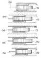
図5は本発明の第2実施の形態に係る超音波プローブの概略構成を示す断面図である。
図に示すように本実施の形態においては、超音波プローブ2の超音波治療手段を挿入軸方向に対して直角方向に回転自在なメカニカルラジアルスキャン型の治療用超音波振動子を配設する代わりに、モータ34aの回転をラックアンドピニオン機構63を介してシャフト64に伝達して治療用振動子20を挿入軸方向(図中矢印方向)に直線運動させて、メカニカルリニア走査させて、治療用振動子20の出射面を処置部位に対設するように位置制御を行うようにしている。その他の構成は前記第1実施の形態と同様であり同部材には同符号を付して説明を省略する。FIG. 5 is a cross-sectional view showing a schematic configuration of an ultrasonic probe according to the second embodiment of the present invention.
As shown in the figure, in the present embodiment, instead of providing a mechanical radial scan type therapeutic ultrasonic transducer capable of rotating the ultrasonic treatment means of the
前記第1実施の形態の図4に示すように例えば、食道などの管腔臓器内61に、まず、超音波プローブ2の挿入部15を挿入していく。このとき、光学観察手段30による光学像並びに超音波観察手段18による超音波診断画像を元に先端部14を治療処置する処置部62の近傍に配置する。そして、超音波プローブ2の操作部8を捻るようにして、挿入軸方向に対して直角方向の位置制御を行って、処置部62をモニタ6に映し出すと共に、モータ34aで治療用超音波振動子20を軸方向に移動させて、治療用超音波振動子20の出射面を処置部62に対設させる。その他の作用及び効果は前記第1実施の形態と同様である。 As shown in FIG. 4 of the first embodiment, for example, the
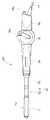
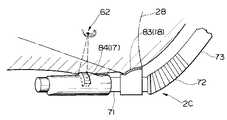
図6ないし図10は本発明の第3実施の形態に係り、図6は腹腔内用の超音波プローブの外形形状を示す説明図、図7は腹腔内用超音波プローブの先端部の概略構成を示す断面図、図8はプローブ先端部の超音波振動子の拡大図、図9は腹腔内用超音波プローブを腹腔内に挿入した状態を示す図、図10は腹腔内用超音波プローブの作用を示す説明図である。 6 to 10 relate to a third embodiment of the present invention, FIG. 6 is an explanatory view showing the outer shape of the intraperitoneal ultrasonic probe, and FIG. 7 is a schematic configuration of the distal end portion of the intraabdominal ultrasonic probe. FIG. 8 is an enlarged view of the ultrasonic transducer at the tip of the probe, FIG. 9 is a view showing a state where the intraabdominal ultrasonic probe is inserted into the abdominal cavity, and FIG. 10 is an illustration of the intraabdominal ultrasonic probe. It is explanatory drawing which shows an effect | action.
図6に示すように本実施の形態においては、超音波診断治療システム1に用いる超音波プローブが腹腔内用超音波プローブ2Aである。この腹腔内用超音波プローブ2Aは、先端側より後述する超音波治療手段17及び超音波観測手段18を内設した先端部71,例えば上下左右方向に湾曲自在な湾曲部72及び硬性な挿入管73を連接して形成した挿入部70と、腹腔内に超音波プローブ2Aの挿入部70を挿抜する際に把持する第1の把持部74と、前記湾曲部72を湾曲操作する湾曲操作ノブ75aを備えた操作部75と、腹腔内に挿抜する際及び腹腔内の超音波プローブ2Aの先端部71を所望の位置に配置させる際に把持する第2の把持部76などから構成されている。 As shown in FIG. 6, in this embodiment, the ultrasonic probe used in the ultrasonic
前記先端部71には生食水などの音響伝達媒体を注入することによって、膨張自在なバルーン71aが着脱自在に取り付けられるようになっている。また、第2の把持部76の後端側からユニバーサルケーブル77を延出している。 An inflatable balloon 71a is detachably attached to the
なお、生食水は、第2の把持部76に設けた注入孔76aより、バルーン71a内に注入されるようになっている。 The saline is injected into the balloon 71 a through an injection hole 76 a provided in the
図7に示すように腹腔内用超音波プローブ2Aの先端部71には先端部71の略中央部に超音波観測手段18として帯状で全周に渡り電子ラジアルアレイ型の観察用超音波振動子78が固定され、この観察用超音波振動子78の両側に超音波治療手段17として帯状で全周に渡り電子ラジアルアレイ型の治療用超音波振動子79,79′とが固定されている。 As shown in FIG. 7, the
図8に示すように治療用超音波振動子79,79′は、同じ曲率で対称的に形成されており、観察用超音波振動子78の照射範囲内に集束するようになっている。観察用超音波振動子78及び治療用超音波振動子79,79′から延出するリード線78a,79a,79bは前記第1実施の形態と同様に図示しない超音波診断治療回路に導出されている。その他の構成は前記第1実施の形態と同様である。 As shown in FIG. 8, the therapeutic
上述のように構成した超音波診断治療システム1の腹腔内用超音波プローブ2Aの作用を説明する。
まず、図9に示すように超音波プローブ2Aの挿入部70は、気腹した腹腔内80にトラカール81を介して挿入して、先端部71を処置部近傍に配置する。次に、処置部近傍に配置させた先端部71が所望の位置(処置部表面にほぼ接触するぐらい)になるように湾曲操作ノブ75aを操作して湾曲部72を湾曲させる。次いで、観察用超音波振動子78を走査させ超音波信号を送受信して、モニター上に臓器内部の病変部を描出する。The operation of the intraabdominal
First, as shown in FIG. 9, the
次に、図10に示すように観察用超音波振動子78の超音波観測領域内に処置部62をとらえた後、治療用超音波振動子79,79′から処置部62に向かって出射される治療用超音波集束ビームの集束点が処置部62の所望の位置となるように、超音波断層画像を参考にバルーン71aを少しづつ膨張させると共に、超音波プローブ2Aの湾曲操作及び治療用超音波振動子79,79′を挿入軸方向に対して直角方向に電子ラジアルスキャンさせて位置調整を行う。 Next, as shown in FIG. 10, the
そして、前記治療用超音波振動子79,79′と処置部62との位置調整が完了した時点で、前記第1実施の形態と同様に治療用超音波振動子79,79′から処置部62に超音波エネルギーを照射して病変組織を焼灼する。 When the position adjustment between the therapeutic
このように、超音波プローブは、軟性鏡に限定されるものではなく、硬性鏡に用いるようにしても良い。その他の作用及び効果は前記第1実施の形態と同様である。 Thus, the ultrasonic probe is not limited to a flexible mirror, and may be used for a rigid mirror. Other operations and effects are the same as those in the first embodiment.
なお、前記第1実施の形態の応用例で示した電子ラジアルアレイ型の観察用超音波振動子78及び治療用超音波振動子79,79′の代わりに、図11に示すように腹腔内用超音波プローブ2Bの先端部71に超音波観測手段18として軸方向に電子リニアアレイ型の観察用超音波振動子81を配設すると共に、超音波治療手段17として治療用超音波振動子82,82′を設け処置部62に対して超音波を軸方向に走査して位置調整を行うようにしても良い。 In place of the electronic radial array type observation
また、図12に示すように腹腔内用超音波プローブ2Cの先端部71の湾曲部前方の先端部手元側部に超音波観測手段18として超音波観測領域28を前方斜視方向に設定したコンベックスアレイ型の観察用超音波振動子83を固定し、先端部71の略中央に超音波治療手段17として電子セクタアレイ型の治療用超音波振動子84を固定して処置部62に対して集束点を位置調整して治療処置が行えるようになっている。この腹腔内用超音波プローブ2Cでは観察用超音波振動子83が前方斜視にオフセットしているため、観察用超音波振動子83と治療用超音波振動子84とを分離して配設することができるため、構成が簡単になると共に、治療用超音波振動子84の開口径を大きく形成して治療効率を高めることができる。 Further, as shown in FIG. 12, a convex array in which an
なお、治療用超音波振動子84は、この治療用超音波振動子84が対設する挿入軸方向に対して直角方向に対して、電子的に超音波照射制御可能になっている。その他の構成は前述の実施の形態と同様であり、同部材には同符号を付して説明を省略する。。 The therapeutic
また、図12に示した電子セクタアレイ型の治療用超音波振動子84を、図13に示すようにドラム85上に治療用超音波振動子86を固定して、例えば操作部内に設けたモータ87の回転をラックアンドピニオン機構88で直線運動に変換してシャフト89に伝達することによって、ドラム85上に固定した治療用超音波振動子86をセクタ走査するようにした、いわゆる、メカニカルセクタ型の治療用超音波振動子84′であっても良い。 In addition, the therapeutic
以下、第1実施の形態を基に他の実施の形態を説明する。
図14は本発明の第4実施の形態に係る超音波プローブ2Dの先端部の概略構成を示す断面図である。Hereinafter, other embodiments will be described based on the first embodiment.
FIG. 14 is a cross-sectional view showing a schematic configuration of a distal end portion of an ultrasonic probe 2D according to the fourth embodiment of the present invention.
図に示すように本実施の形態では前記第1実施の形態の超音波治療手段17である治療用超音波振動子20を固定部材20aに固定してモーター34aの回転をフレキシブルシャフト22aに伝達してメカニカルラジアル走査させていたのに対して、固定部材20aに超音波治療手段17としてリニア型振動子アレイの超音波振動子91を固定している。このリニア型振動子アレイの超音波振動子91から操作部側に導出したリード線92を介して軸方向の走査を電子的に可能としている。また、第1実施の形態と同様に手元側のモータ34aを回転させることでメカニカルラジアル的走査が可能である。すなわち、本実施の形態において超音波治療手段17である治療用超音波振動子91は、電子リニア的走査及びメカニカルラジアル的に走査の両方が可能となっている。その他の構成は前記第1実施の形態と同様であり、同部材には同符号を付して説明を省略する。 As shown in the figure, in the present embodiment, the therapeutic
上述のように構成した超音波治療診断システムでは、挿入部先端部14を前記第1実施の形態と同様に処置部近傍まで挿入後、観察用超音波振動子24をメカニカルラジアル走査させて処置部位の超音波断層画像を得る。そして、モニタ上の超音波断層画像を観察しながら、治療用のリニア型振動子アレイの超音波振動子91を電子リニア走査させて軸方向の制御を行う一方、モータ34aの回転で前記超音波振動子91をメカニカルラジアル走査させて軸方向に対して直角方向の位置制御を行うと共に、バルーン33aの膨張量を調整して深さ方向の距離調整を行って、処置部に対する集束点の位置調整終了後、超音波を処置部に照射するようになっている。その他の作用は前記第1実施の形態と同様である。 In the ultrasonic therapy diagnosis system configured as described above, after inserting the
このように、超音波治療手段である超音波振動子をリニア型振動子アレイとして、軸方向の走査を電子走査可能とすると共に、手元側で軸方向に対して直角方向にメカニカルラジアル走査可能とし、且つ、バルーンの膨張量で深さ方向の制御を可能としているため、処置部に対して照射する超音波の集束点を三次元的に位置調整することができるので、超音波の処置部への照射精度を向上させて、治療処置を確実に行うことができる。 In this way, the ultrasonic transducer as an ultrasonic therapy means is a linear transducer array, and the axial scanning can be electronically scanned, and the mechanical radial scanning can be performed in the direction perpendicular to the axial direction at the hand side. In addition, since the depth direction can be controlled by the amount of balloon expansion, the focal point of the ultrasonic wave irradiated to the treatment part can be adjusted three-dimensionally. The irradiation accuracy can be improved and the therapeutic treatment can be performed reliably.
なお、前記超音波治療手段である超音波振動子をリニア型振動子アレイにする代わりに、先端側に配設した超音波観測手段である電子ラジアル型振動子アレイを手元側の操作部に配設したモータに接続してメカニカルリニア走査可能とする構成としても同様の効果を得ることができる。また、先端側に配設した超音波観測手段である電子セクタ型振動子アレイを手元側の操作部に配設したモータに接続してメカニカルリニア走査可能とする構成であっても良い。さらに、先端側に配設した超音波観測手段であるメカニカルセクタ型振動子を手元側の操作部に配設したモータに接続してメカニカルリニア走査可能とする構成にしても良い。さらに又、先端側に配設した超音波観測手段であるメカニカルリニア型振動子を手元側の操作部に配設したモータに接続してメカニカルラジアル走査可能とする構成にしても良い。 Instead of using a linear transducer array as an ultrasonic transducer as the ultrasonic treatment means, an electronic radial transducer array as an ultrasonic observation means arranged at the distal end side is arranged at the operation unit on the hand side. A similar effect can be obtained even if the configuration is such that mechanical linear scanning is possible by connecting to a provided motor. Further, an electronic sector type transducer array, which is an ultrasonic observation means disposed on the distal end side, may be connected to a motor disposed on the operation unit on the hand side to enable mechanical linear scanning. Further, a mechanical sector type transducer that is an ultrasonic observation means disposed on the distal end side may be connected to a motor disposed on the operation unit on the hand side to enable mechanical linear scanning. Further, a mechanical linear type transducer that is an ultrasonic observation means disposed on the distal end side may be connected to a motor disposed on the operation unit on the hand side so that mechanical radial scanning is possible.
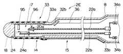
図15は本発明の第5実施の形態に係る超音波プローブ2Eの先端部の概略構成を示す断面図である。 FIG. 15 is a cross-sectional view showing a schematic configuration of a distal end portion of an
図に示すように本実施の形態においては、前記第1実施の形態と同様、超音波観測手段18である観察用超音波振動子24が固定部材24aに固定され、手元側の操作部内に配設したモータ34bの回転をフレキシブルシャフト22bに伝達してメカニカルラジアル走査可能である。そして、超音波治療手段17としては治療用の平板振動子95が先端部14の先端側に固定される一方、モータ34aの回転をフレキシブルシャフト22aに伝達して回転可能な固定部材20aには前記治療用平板振動子95から出射される超音波を所定の方向に反射するための反射出射面鏡96を固定している。その他の構成は前記第1実施の形態と同様であり、同部材には同符号を付して説明を省略する。 As shown in the figure, in the present embodiment, as in the first embodiment, the observation
上述のように構成した超音波治療診断システムでは、挿入部先端部14を前記第1実施の形態と同様に処置部近傍まで挿入後、観察用超音波振動子24を手元側の操作部8に配設したモータ34bの回転でメカニカルラジアル走査させて処置部の超音波断層画像を得る。そして、モニタ上の超音波断層画像を観察しながら、手元側の操作部8に配設したモータ34aを回転させて反射出射面鏡96をメカニカルラジアル走査して、処置部に対する反射出射面鏡96の集束位置制御を行う。集束位置制御後、先端に固定した治療用の平板振動子95から超音波を反射出射面鏡96に向かって出射する。すると、平板振動子95から出射した超音波は、反射出射面鏡96で反射して、目的とする処置部に超音波が集束して処置が行えるようになっている。その他の作用及び効果は前記実施の形態と同様である。 In the ultrasonic therapy diagnosis system configured as described above, after inserting the insertion portion
図16は本発明の第6実施の形態に係る超音波プローブ2Fの先端部の概略構成を示す断面図である。 FIG. 16 is a cross-sectional view showing a schematic configuration of a distal end portion of an
図に示すように本実施の形態においては、超音波観測手段18として超音波プローブ2Fの先端部に観察用電子リニア型振動子アレイ101を配設し、この観察用電子リニア型振動子アレイ101から手元側に導出したリード線102で軸方向の観察が可能となっている。 As shown in the figure, in the present embodiment, an observation electronic
一方、超音波治療手段17である治療用超音波振動子20は、前記第1実施の形態と同様に固定部材20aに固定されているが、この固定部材20aはシャフト103が接続されている。このシャフト103は、超音波プローブ手元側の操作部8に配設したモータ104の回転を直線運動に変換するラックアンドピニオン機構105によって軸方向に対して直線運動するようになっている。 On the other hand, the therapeutic
なお、超音波プローブ2Fの先端部14のシャフト103に接するように、シャフト103の直線運動を回転運動に変換する変換部106と、この変換部106の回転量を読み取ってシャフト103の直線運動距離を計測する小型エンコーダ107が接続されている。その他の構成は前記第1実施の形態と同様であり、同部材には同符号を付して説明を省略する。 A
上述のように構成した超音波治療診断システムでは、挿入部先端部14を前記第1実施の形態と同様に処置部近傍まで挿入後、まず、観察用電子リニア型振動子アレイ101を走査させて処置部の軸方向の観察を行う。次いで、処置部が定まった時点で、モータ104の回転をラックアンドピニオン機構105を介してシャフト103を直線駆動させて、治療用超音波振動子20をリニア走査する。このとき、治療用超音波振動子20の軸方向への移動量を変換部106,小型エンコーダ107で読み取ると共に、前記観察用電子リニア型振動子アレイ101の超音波断層画像と検出した移動量とを元にして、モータ104の回転量を調節し、治療用超音波振動子20の軸方向への移動量を数値的に制御することによって、移動量を適宜調整して、治療用超音波振動子20から出射される超音波を治療部位に効率良く集束することができる。その他の作用は前記実施の形態と同様である。 In the ultrasonic therapy diagnosis system configured as described above, after the insertion portion
このように、治療用超音波振動子の軸方向への移動量を変換部を介してエンコーダで読み取ることによって、治療用超音波振動子から出射される超音波の治療部位への集束精度を向上させることができる。その他の効果は前記第1実施の形態と同様である。 In this way, the amount of movement of the therapeutic ultrasonic transducer in the axial direction is read by the encoder via the converter, thereby improving the focusing accuracy of the ultrasonic wave emitted from the therapeutic ultrasonic transducer to the treatment site. Can be made. Other effects are the same as those of the first embodiment.
なお、治療用超音波振動子の移動量を検出するエンコーダは、先端部のみに配設するように構成されるものではなく、先端部及び手元側部の両方、或は、手元側部のみに設けるように構成しても良い。 Note that the encoder for detecting the amount of movement of the therapeutic ultrasonic transducer is not configured to be disposed only at the distal end, but only at the distal end and the proximal side, or only at the proximal side. You may comprise so that it may provide.
図17ないし図19は本発明の第7実施の形態に係り、図17は超音波プローブ2Fの先端部の概略構成を示す図、図18は回転検出部の構成を示す拡大図、図19は回転検出部の回路図である。 FIGS. 17 to 19 relate to a seventh embodiment of the present invention, FIG. 17 is a diagram showing a schematic configuration of the distal end portion of the
図17に示すように超音波プローブ2Gの先端部14には前記第1実施の形態と同様に、治療用超音波振動子20及び観察用超音波振動子24は、固定部材20a,24aに各々固定して設けられ、図示しないモータの回転をフレキシブルシャフト22a,22bに伝達してメカニカルラジアル走査可能な構成となっている。そして、前記治療用超音波振動子20を回転させるフレキシブルシャフト22aに後述する回転検出部111を設けている。 As shown in FIG. 17, at the
図18に示すように回転検出部111は、治療用超音波振動子20に対して並列にインダクタ112を接続し、このインダクタ112の外側に治療用超音波振動子20の回転に応じてインダクタ112に電磁誘導による起電力が発生させるうに永久磁石113,113′を配設している。治療用超音波振動子20にはフレキシブルシャフト22aの一端が接続され、このフレキシブルシャフト22aの他端は図示しない駆動ユニット内のモータの回転軸に連結するようになっている。 As shown in FIG. 18, the rotation detection unit 111 connects an
また、治療用超音波振動子20及びインダクタ112には同軸ケーブル114が接続され、この同軸ケーブル114がフレキシブルシャフト22aの略中心を挿通して後述する送受信回路に接続するようになっている。 A
図19に示すように治療用超音波振動子20から延出する同軸ケーブル114はスリップリング115を介して送受信切り換え回路116に接続されている。そして、送受信切り換え回路116は、送受駆動パルスを発生する駆動パルサ回路117,プリアンプ118にそれぞれ接続している。 As shown in FIG. 19, the
前記プリアンプ118の出力は、ローパスフィルタ(LPF)119を介してコンパレータ120に供給され、このコンパレータ120の出力がエンコーダ121に供給される。エンコーダ121の出力は、駆動パルサ回路117の制御回路122に供給されるようになっている。 The output of the
上述のように構成した超音波治療診断システムでは、挿入部先端部14を前記第1実施の形態と同様に処置部近傍まで挿入後、観察用超音波振動子24で目的患部の横方向の観察を行う。そして、前記観察用超音波振動子24からの超音波断層画像及び回転検出部111からの検出振動(治療用超音波振動子20の回転によって発生する電極誘導で発生する振動)を読み取り、治療用超音波の集束位置を決定して、位置補正が必要な場合には検出信号を元にモータで治療用超音波振動子20を回転させ、適宜な位置となるように位置補正を行う。その後、治療用超音波振動子20から超音波を処置部に照射して治療処置が行なえるようになっている。 In the ultrasonic therapy diagnosis system configured as described above, the insertion portion
このように、治療用超音波振動子の近傍にその挿入軸方向に対して直角方向の移動量を読み取る検出部を設けることにより、前記第6実施の形態と同様に、治療部位への超音波の集束度を向上させることができる。 In this way, by providing a detection unit that reads the amount of movement in the direction perpendicular to the insertion axis direction in the vicinity of the therapeutic ultrasonic transducer, as in the sixth embodiment, ultrasonic waves to the treatment site are obtained. The degree of focusing can be improved.
図20は本発明の第8実施の形態に係る治療用超音波振動子のリニア走査を示す説明図である。 FIG. 20 is an explanatory view showing linear scanning of the therapeutic ultrasonic transducer according to the eighth embodiment of the present invention.
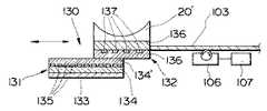
本発明は前記第6実施の形態の超音波プローブ2Fに設けた治療用超音波振動子20′のリニア走査を手元側に設けたモータ104で行う代わりに、先端部14に設けた静電モータ130で行うようにしたものである。 In the present invention, instead of performing linear scanning of the therapeutic
前記静電モータ130は、ステータ131と、これに対設するロータ132とで構成されており、ステータ131は例えば、シリコン半導体基板133上に二酸化シリコンや窒化シリコンなどで形成した第1の絶縁層134が設けられ、第1の絶縁層134上に第2の絶縁層134′が設けられ、第1の絶縁層134と第2の絶縁層134′との間にアルミニウムなどで形成した複数の電極135を設けて形成されている。 The
一方、ロータ132は、第1の絶縁層136下に第2の絶縁層136′が固定され、第1の絶縁層136と第2の絶縁層136′との間に複数の電極137を設けている。 On the other hand, the
そして、前記ステータ131の第2の絶縁層134′と、ロータ132の第2の絶縁層136′とが摺動自在に摺接している。 The second
なお、前記ステータ131に設けられている電極135のピッチは、ロータ132に設けられている電極137のピッチより短く設定しているので、電極に電圧を印加することで、ロータ132はステータ131に対して左右即ち挿入部軸方向に移動するようになっている。また、前記ロータ132にはシャフト103が接続されている。その他の構成は前記第6実施の形態と同様であり、同部材には同符号を付して説明を省略する。 Since the pitch of the
上述のように構成した超音波治療診断システムでは、挿入部先端部14を前記第1実施の形態と同様に処置部近傍まで挿入後、処置部が定まった時点で、静電モータ130の電極135に電圧を印加し、シャフト103を直線駆動させて、治療用超音波振動子20′をリニア走査する。このとき、治療用超音波振動子20′の軸方向への移動量を変換部106,小型エンコーダ107で読み取ると共に、前記観察用電子リニア型振動子アレイ101の超音波断層画像と検出した移動量とを元にして、治療用超音波振動子20′の軸方向への移動量を数値的に制御することによって、移動量を適宜調整して、治療用超音波振動子20′から出射される超音波を治療部位に効率良く集束することができる。その他の作用は前記第6実施の形態と同様である。 In the ultrasonic therapy diagnosis system configured as described above, after the insertion portion
このように、前記第6実施の形態と同様に治療用超音波振動子の移動量をエンコーダで読み取るため、治療部位への超音波集束精度が向上するばかりでなく、先端アクチュエータにより治療用振動子が駆動するため、術者の操作性が大幅に向上する。 As described above, since the amount of movement of the therapeutic ultrasonic transducer is read by the encoder as in the sixth embodiment, not only the accuracy of ultrasonic focusing to the treatment site is improved, but also the therapeutic transducer is provided by the tip actuator. Because of this, the operability for the surgeon is greatly improved.
なお、図21及び図22に示すように静電モータ130にシャフト138の一端を接続し、このシャフト138の他端を治療用超音波振動子139aを固定したドラム139に固定して、静電モータ130の直線運動により、治療用超音波振動子139aをセクタ走査させるようにしても良い。このとき、ドラム139の近傍にエンコーダ107を接続すれば、ドラム139の移動量を検出することによって治療用超音波振動子139aの位置を正確に把握することができるので、治療部位への超音波の集束精度が向上する。 As shown in FIGS. 21 and 22, one end of a
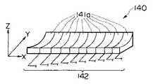
図23は本発明の第9実施の形態に係る治療用超音波振動子の概略構成を示す説明図である。 FIG. 23 is an explanatory diagram showing a schematic configuration of the therapeutic ultrasonic transducer according to the ninth embodiment of the present invention.
図に示すように治療用超音波振動子140は、一定の曲率で構成された複数の治療用超音波振動子141a,141a,141a...からなるフェーズドアレイを挿入軸に対して先端側から順次で配列させて形成したものであり、各々の治療用超音波振動子141a,,141a,141a...から延出するリード線142が手元側の図示しない制御部に接続されている。 As shown in the figure, the therapeutic
上述のように構成された治療用超音波振動子140は、一定の曲率の治療用超音波振動子141a,141a,141a...を複数配設して形成されているので、Y方向の集束位置は曲率によって一義的に決定する。そして、図示しない手元側の制御部からリード線142を介して印加する電圧を制御することによって、XZ方向の集束位置が所望の位置となるようになっている。 The therapeutic
このように、フェーズドアレイを用いて治療用超音波振動子を形成することによって、印加する電圧を制御することによって、超音波集束位置を制御して超音波の集束精度を向上させることができる。 Thus, by forming a therapeutic ultrasonic transducer using a phased array, by controlling the voltage to be applied, the ultrasonic focusing position can be controlled and the ultrasonic focusing accuracy can be improved.
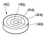
なお、前記軸方向に配列されたの一定の曲率のフェーズドアレイ141aの代わりに図24に示すような円形型のアニュラ振動子141bを中心側から順次配列して、挿入軸方向に対して直角方向の超音波の集束制御を行うようにしてもよい。また、図示しない厚みが連続的に変化する単板出射面振動子で集束点深さ制御を行うようにしても良い。 In addition, instead of the phased array 141a having a constant curvature arranged in the axial direction, circular
図25ないし図28は本発明の第10実施の形態に係り、図25は超音波プローブ2Gの先端部の概略構成を示す図、図26は治療用超音波振動子の集束点を調整する状態を示す図、図27は治療用超音波振動子の概略構成を示す平面,背面及び側面図、図28は超音波プローブ2Gの全体構成の概略を示す図である。 25 to 28 relate to the tenth embodiment of the present invention, FIG. 25 is a diagram showing a schematic configuration of the distal end portion of the
図25に示すように超音波観測手段18である診断用超音波振動子24は、固定部材24aに固定されており、この固定部材24aに一端を固定した回転自在な回転シャフト151によりラジアルスキャン可能となっている。 As shown in FIG. 25, a diagnostic
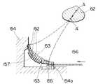
一方、図25及び図27に示すように超音波治療手段17は、複数の治療用超音波振動子152,152,152...をシリコン,ウレタンなど弾性板153上に配設して形成している。この弾性板153の一端部は、内視鏡先端部154に固定され、他端部はガイド部材155に固定されている。 On the other hand, as shown in FIGS. 25 and 27, the ultrasonic treatment means 17 includes a plurality of therapeutic
図26に示すように前記ガイド部材155は、内視鏡先端部154に形成した溝部154aに摺動自在に配設されている。なお、ガイド部材155は、このガイド部材155に接続したワイヤ156を押し引きして溝部154aを軸方向に摺動させることによって、弾性板153を所定の曲率で撓ませて超音波の処置部に対する集束点を集束点Aや集束点A′のように変化させることができるようになっている。 As shown in FIG. 26, the
そして、前記弾性板153の裏面にはこの弾性板153の撓み量を検出するためのひずみセンサ157が設けられている。 A
図27及び図29に示すように前記弾性板153の治療用超音波振動子152,152,152...は電極158a,158bを介してリード線159と接続され、手元側の操作部8に導出している。また、ひずみセンサ157の両端は、電極161a,161bを介してリード線160と接続され、手元側の操作部8に導出している。 As shown in FIGS. 27 and 29, the therapeutic
なお、前記図25に示すように内視鏡の先端部には管路162に連通するバルーン33aが設けられている。 As shown in FIG. 25, a
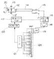
上述のように構成した超音波診断治療システム1は、図28に示すように超音波プローブ2Gに配設したCCDなどの画像素子32bでとらえた光学像をビデオプロセッサ163を介してTVモニタ164に映し出す一方、超音波観測手段18で送受した電気信号を超音波画像用プロセッサ165を介してTVモニタ166に超音波診断画像として映し出すようになっている。 In the ultrasonic
そして、複数の治療用超音波波振動子152を弾性板153に固定して構成した超音波治療手段17は、振動子駆動回路167に接続され、この弾性板153の裏面に配設されたひずみセンサ157はひずみ量検出部168,集束点検出部169,及び超音波画像用プロセッサ165にそれぞれ接続して、弾性板153の撓み量をひずみセンサ157でとらえ、このひずみ量から超音波の集束点位置を演算してTVモニタ166に表示することができるようになっている。 The ultrasonic treatment means 17 configured by fixing a plurality of therapeutic
このため、先端部に配設したバルーン33aを膨張させた後、TVモニタ166を観察しながらワイヤ156を押し引きして、弾性板153を湾曲させることによって、ひずみセンサ157が弾性板153の撓み量を検出し、ひずみ量検出部168及び集束点検出部169で演算した超音波集束点をTVモニタ166上で確認しながら適宜な位置になるように調整する。 For this reason, after inflating the
このように、超音波治療手段である治療用超音波振動子を湾曲自在な弾性板に配設して構成したことにより、ワイヤを押し引きして弾性板の湾曲率を変化させることにより、超音波集束点位置を移動することができる。 In this way, by arranging the ultrasonic transducer for treatment, which is an ultrasonic treatment means, on a bendable elastic plate, it is possible to push and pull the wire to change the bending rate of the elastic plate. The position of the acoustic wave focusing point can be moved.
また、弾性板に取り付けたひずみセンサによって治療用超音波振動子を取り付けた弾性板の撓み量を演算で求め、超音波集束点をTVモニタ上に表示して、作業性を大幅に向上させることができる。 In addition, the amount of bending of the elastic plate attached with the therapeutic ultrasonic transducer can be calculated by a strain sensor attached to the elastic plate, and the ultrasonic focusing point is displayed on the TV monitor, thereby greatly improving workability. Can do.
図29ないし図31は本発明の第11実施の形態に係り、図29は治療用超音波振動子の集束点調整手段を示す図、図30は集束点調整手段の圧電アクチュエータの動作を説明する図、図31は圧電アクチュエータに負荷する電圧パターンを示す図である。 FIGS. 29 to 31 relate to the eleventh embodiment of the present invention, FIG. 29 is a diagram showing the focusing point adjusting means of the therapeutic ultrasonic transducer, and FIG. 30 is a diagram for explaining the operation of the piezoelectric actuator of the focusing point adjusting means. FIG. 31 is a diagram showing a voltage pattern applied to the piezoelectric actuator.
図29に示すように本実施の形態においては前記第10実施の形態の複数の超音波治療用振動子152を配設した弾性板153をワイヤ156の押し引き動作で撓ませて湾曲率を変化させる代わりに、内視鏡先端に配設した圧電アクチュエータ170で行なうようにしたものである。この圧電アクチュエータ170は、本出願人が特願平5―44140号に提案しているものであり、移動体171及び積層圧電素子172から構成されており、図31の(a)に示すような電圧パターンをa、b、cや同図(b)に示すような電圧パターンをd、eと変化させることにより、図30に示すように積層圧電素子172が電圧パターンに対応して伸縮して移動体171を軸方向に移動させて、弾性板の湾曲率を変化させるようになっている。その他の構成及び作用は前記第9実施の形態と同様であり、同部材には同符号を付して説明を省略する。 As shown in FIG. 29, in this embodiment, the
このように、治療用超音波振動子を固定している湾曲板の湾曲率を変化させる際、、圧電アクチュエータを駆動する電圧を印加するだけで、弾性板を所望の量だけ撓ませて、超音波集束点を容易に変化させることができる。その他の効果は前述の実施の形態と同様である。 In this way, when changing the curvature rate of the curved plate to which the therapeutic ultrasonic transducer is fixed, the elastic plate is bent by a desired amount only by applying a voltage for driving the piezoelectric actuator. The sound wave focusing point can be easily changed. Other effects are the same as those of the above-described embodiment.
図32は本発明の第12実施の形態に係る超音波プローブ2Hの先端部の概略構成を示す図である。 FIG. 32 is a diagram showing a schematic configuration of the distal end portion of the
本実施の形態においては、超音波プローブ2Hの先端部14にモータ181を内蔵し、このモータ181の回転によって診断用超音波振動子24を回転させてメカニカルラジアル走査可能としている。 In the present embodiment, a
また、超音波プローブ2Hの先端部14に曲率がR,R′と異なる、すなわち集束点の異なる2つの治療用超音波振動子182a,182bを予め固定している。その他の構成は前述の実施の形態と同様であり、同部材には同符号を付して説明を省略する。 Further, two therapeutic
このように、診断用超音波振動子に直接モータの回転を伝達して回転させることにより、安定したメカニカルラジアル走査が可能となる。 Thus, stable mechanical radial scanning is possible by transmitting the rotation of the motor directly to the diagnostic ultrasonic transducer and rotating it.
また、集束点の異なる治療用超音波振動子を配設したことにより、治療処置に対応する集束点を有する治療用超音波振動子を用いることによって的確に処置部の処置治療を行うことができる。その他の作用及び効果は前述の実施の形態と同様である。 In addition, since the therapeutic ultrasonic transducers having different focal points are arranged, the treatment treatment of the treatment section can be performed accurately by using the therapeutic ultrasonic transducers having the focal points corresponding to the therapeutic treatment. . Other operations and effects are the same as those of the above-described embodiment.
さらに、同時に2つの治療用超音波振動子から超音波を照射することで、広範な治療部位を同時に処置治療することができる。 Furthermore, by irradiating ultrasonic waves from two therapeutic ultrasonic transducers simultaneously, a wide range of treatment sites can be treated and treated simultaneously.
なお、本実施の形態では曲率の異なる治療用超音波振動子を2つ設けるようにしているが、先端部に配設する治療用超音波振動子は、2つに限定されるものではなく、3つ以上の治療用超音波振動子を設けるようにしても良い。 In this embodiment, two therapeutic ultrasonic transducers having different curvatures are provided. However, the number of therapeutic ultrasonic transducers disposed at the distal end is not limited to two. Three or more therapeutic ultrasonic transducers may be provided.
また、図33に示すように前記図32に示した曲率がR,R′と異なる2つの治療用超音波振動子182a,182bを配設する代わりに、平板振動子185a,185b上に曲率がR,R′と異なる音響レンズ186a、186bを設けるようにしても同様の作用及び効果を得ることができる。 Further, as shown in FIG. 33, instead of disposing two therapeutic
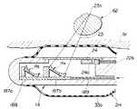
さらに、図34及び図35に示すように超音波プローブ2Hの先端部14の内部に観察用超音波振動子24を固定する固定部材24aにフレキシブルシャフト22bを固定してメカニカルラジアル走査可能とする一方、超音波集束点位置を制御するバルーン33aを設けると共に、この超音波プローブ2Hの先端部14に曲率R3 ,R4 の2つの異なる治療用超音波振動子187a,187bを軸方向に摺動自在な摺動ユニット188上に固定している。なお、ワイヤ189を押し引きすることで、摺動ユニット188が内視鏡先端部内の軸方向に摺動させて治療に適した超音波集束点23aを有する治療用超音波振動子を適宜選択することができる。 Further, as shown in FIGS. 34 and 35, the
図36は本発明の第13実施の形態に係り、同図の(a)は超音波プローブ2Iの先端部の概略構成を示す図、同図の(b)は超音波プローブ先端部に着脱自在に設けられる振動子ユニット単体を示す図である。 FIG. 36 relates to a thirteenth embodiment of the present invention. FIG. 36 (a) is a diagram showing a schematic configuration of the tip of the ultrasonic probe 2I, and FIG. 36 (b) is detachable from the tip of the ultrasonic probe. It is a figure which shows the vibrator unit single-piece | unit provided in.
同図(a)に示すように超音波プローブ2Iの先端部14には曲率R1 の治療用超音波振動子191aを配設した第1の振動子ユニット190aが着脱自在に設けられている。前記振動子ユニット190aの上部には弾性膜192が設けられ、振動子ユニット190a内部には生食水などの充填物193が充填されている。 As shown in FIG. 6A, a first transducer unit 190a having a therapeutic ultrasonic transducer 191a having a curvature R1 is detachably provided at the
そして、超音波プローブ本体に内蔵されたリード線194と振動子ユニット190aの電極195とが装着状態で電気的に接続するようになっている。 The
なお、同図(b)の符号190bは、前記振動子ユニット190aと交換可能な外形形状が第1の振動子ユニット190aと同じな第2の振動子ユニットであり、振動子ユニット内部に曲率R2 の治療用超音波振動子191b、弾性膜192、充填物193を内蔵して超音波の集束点を換えられるようになっている。
体腔内に振動子ユニット190aを配設した超音波プローブ2Iを挿入した後、治療用超音波振動子191aから治療用超音波を処置部に向かって照射する。このとき万一、超音波集束点が合わないようなら、超音波プローブ2Iを一旦、体腔内から抜去して、適切な超音波集束点を有する別の振動子ユニット190bに交換して処置部の治療処置を行うことができる。 After inserting the ultrasonic probe 2I having the transducer unit 190a in the body cavity, the therapeutic ultrasonic wave is irradiated from the therapeutic ultrasonic transducer 191a toward the treatment portion. If the ultrasonic focusing point does not match at this time, the ultrasonic probe 2I is once removed from the body cavity and replaced with another
このように、曲率の異なる治療用振動子を有する振動子ユニットを形成して、超音波プローブに対して交換可能とすることにより、様々な超音波集束点を有する超音波プローブを提供することができる。 Thus, an ultrasonic probe having various ultrasonic focusing points can be provided by forming a transducer unit having therapeutic transducers having different curvatures and making it replaceable with the ultrasonic probe. it can.
また、振動子ユニットを交換する構成とすることによって先端部の形状を簡略することができることにより、プローブ本体の細径化を図ることができる。 In addition, the configuration of exchanging the transducer unit can simplify the shape of the tip, thereby reducing the diameter of the probe body.
さらに、治療用振動子を交換可能としているため、治療用振動子及び超音波プローブの洗浄,消毒,滅菌を容易に行うことができる。 Further, since the therapeutic transducer can be replaced, the therapeutic transducer and the ultrasonic probe can be easily cleaned, disinfected, and sterilized.
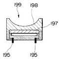
なお、図37に示すように出射面型超音波振動子191a,191bを配設した振動子ユニット190a,190bの代わりに、平板型振動子197を設け、この平板型振動子197の上部に出射面型音響レンズ198を固定して形成する振動子ユニット199であっても良い。 As shown in FIG. 37, instead of the
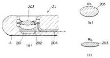
図38は本発明の第14実施の形態に係り、図38の(a)は本発明の第14実施の形態に係る超音波プローブ2Jの先端部の概略構成を示す図、同図の(b)は音響レンズ厚みを厚くして焦点を変えた状態を示す図、同図の(c)は音響レンズ厚みを薄くして焦点を変えた状態を示す図である。 FIG. 38 relates to a fourteenth embodiment of the present invention, and FIG. 38 (a) is a diagram showing a schematic configuration of a distal end portion of an
図の(a)に示すように超音波プローブ2Jの先端部14には、平板の治療用超音波振動子201と、音響レンズ202と、焦点可変用音響レンズ203とが配設されている。 As shown in (a) of the figure, a flat-plate therapeutic
焦点可変用音響レンズ203は、弾性袋体の中に生食水やゲル状物質などが封入されており、この焦点可変用音響レンズ203の端部に接続したワイヤ204を進退させることによって、図(b),図(c)に示すように焦点可変用音響レンズ203の曲率を例えばR5 ,R6 と変化させて、治療用超音波振動子から出射されるの超音波集束点を可変することができるようになっている。その他の構成及び作用効果は前述の実施の形態と同様であり、同部材には同符号を付して説明を省略する。
ところで、内視鏡像や超音波像,X線像あるいはCT像など様々な像を観察しながら治療処置を施す場合、術者は、それぞれの像が写し出されているモニタ画面に視野を移動して像の観察を行っていた。しかしながら、それぞれの像が写し出されているモニタ画面に視野を移動させて観察させていたのでは瞬時に適切な像を選択することができなかった。そこで、図39ないし図42に示すような像観察手段を設けることによって術者の負担を軽減して瞬時に適切な画像を選択することができる。The focus-changing
By the way, when performing treatment while observing various images such as an endoscopic image, an ultrasonic image, an X-ray image, or a CT image, the operator moves the field of view to the monitor screen on which each image is projected. The image was observed. However, if the field of view is moved to the monitor screen on which each image is projected for observation, an appropriate image cannot be selected instantaneously. Therefore, by providing image observation means as shown in FIGS. 39 to 42, the burden on the operator can be reduced and an appropriate image can be selected instantaneously.
図39に示すように像観察手段であるフェイスマウントディスプレイ(以下FMDと記載)301には3次元位置センサ302と、レンズ等の光学部303と、液晶ディスプレイ304などが内蔵されている。そして、このFMD301には画像切換え部305が接続されている。この画像切換え部305に超音波画像用プロセッサ306,ビデオプロセッサ307,CT画像ファイル308,X線画像ファイル309が接続されると共に、3次元位置センサ受信部310,位置演算部311が接続されている。 As shown in FIG. 39, a face mount display (hereinafter referred to as FMD) 301 as an image observation means includes a three-
すなわち、FMD301の液晶ディスプレイ304には画像切換え部305に接続された超音波画像用プロセッサ306,ビデオプロセッサ307,CT画像ファイル308,X線画像ファイル309から超音波像,内視鏡像,CT像,X線像が表示されるようになっている。 That is, the
図40に示すように例えば、術者Aが患者Bに超音波プローブ2を挿入する場合、まず、図41の(a)に示すように、3次元位置センサ302の初期状態設定後、FMD301を前方・水平方向に向けた状態のとき、内視鏡像312がFMD301の液晶ディスプレイ304に表示され、次に、FMD301を水平方向に対してθz上向きにしたとき、MRI画像313が液晶ディスプレイ304に表示され、FMD301を水平方向に対して−θZ 下向きにしたとき、液晶ディスプレイ304がシースルー状態となって患者を見ることができるように設定する。 As shown in FIG. 40, for example, when the operator A inserts the
次いで、図の(b)に示すようにFMD301を前方方向に対してθxy傾けた状態のとき、FMD301の液晶ディスプレイ304に超音波画像314が表示される。又、FMD301を前方方向に対してθxy傾けた状態でFMD301を水平方向に対してθZ 上向きにしたとき、X線画像315が液晶ディスプレイ304に表示され、FMD301を水平方向に対してθxy傾けた状態でFMD301を水平方向に対して−θZ 下向きにしたとき、FMD301がシースルーと状態となって、患者を見ることができるようにしている。このため、術者は身体の向きを上下左右方向に移動させることによって所望の像を得ることができ、術者の操作性が向上する。 Next, when the
なお、前記図40に示すようにMRI像313,内視鏡像312,X線画像315,超音波画像314を手術室や検査室の大モニターに映し出すようにすれば、複数の術者によって診断を行うことができる。 As shown in FIG. 40, if the
[付記]
(1)上部消化管,下部消化管,腹腔等の体腔内に挿入可能な細管を備えると共に、超音波を用いて生体の治療を行う超音波治療手段及び超音波を用いて生体の診断を行う超音波観測手段を備えた細管を有する超音波診断治療システムにおいて、前記細管に超音波治療手段から処置部位へ出射する超音波を処置部位の所定位置に集束させる超音波集束点調整手段を設けた超音波診断治療システム。[Appendix]
(1) Provided with tubules that can be inserted into body cavities such as the upper digestive tract, the lower digestive tract, and the abdominal cavity, and ultrasonic treatment means for treating the living body using ultrasound and diagnosis of the living body using ultrasound In the ultrasonic diagnostic treatment system having a thin tube provided with ultrasonic observation means, an ultrasonic focusing point adjusting means for focusing the ultrasonic wave emitted from the ultrasonic therapeutic means to the treatment site on the capillary tube is provided on the thin tube. Ultrasound diagnostic treatment system.
(2)前記体腔内に挿入可能な細管が可撓性プローブである付記1記載の超音波診断治療システム。 (2) The ultrasonic diagnostic treatment system according to
細管を上部消化管,下部消化管など複雑な湾曲形状の体腔内に挿入を行える。 The tubules can be inserted into complex curved body cavities such as the upper and lower digestive tracts.
(3)前記体腔内に挿入可能な細管が硬性プローブである付記1記載の超音波診断治療システム。 (3) The ultrasonic diagnostic treatment system according to
(4)前記超音波集束点調整手段がプローブ先端部に配設するバルーンである付記1記載の超音波診断治療システム。 (4) The ultrasonic diagnostic treatment system according to
超音波集束点をバルーンの膨張量で調整することによって深さ方向の位置調整を確実に行える。 The position adjustment in the depth direction can be reliably performed by adjusting the ultrasonic focusing point by the balloon expansion amount.
(5)前記超音波治療手段がメカニカルラジアル走査方式であり、メカニカルラジアル走査で焦点位置制御を行う付記1記載の超音波診断治療システム。 (5) The ultrasonic diagnostic treatment system according to
(6)前記超音波治療手段が電子ラジアル走査方式であり、電子ラジアル走査で焦点位置制御を行う付記1記載の超音波診断治療システム。 (6) The ultrasonic diagnostic treatment system according to
(7)前記超音波治療手段が電子セクタ走査方式であり、電子セクタ走査で焦点位置制御を行う付記1記載の超音波診断治療システム。 (7) The ultrasonic diagnostic treatment system according to
(8)前記超音波治療手段がメカニカルセクタ走査方式であり、メカニカルセクタ走査で焦点位置制御を行う付記1記載の超音波診断治療システム。 (8) The ultrasonic diagnostic treatment system according to
(9)前記超音波治療手段がメカニカルリニア走査方式であり、メカニカルリニア走査で焦点位置制御を行う付記1記載の超音波診断治療システム。 (9) The ultrasonic diagnostic treatment system according to
(10)前記超音波治療手段が電子リニア走査方式であり、電子リニア走査で焦点位置制御を行う付記1記載の超音波診断治療システム。 (10) The ultrasonic diagnostic treatment system according to
(11)前記超音波治療手段を超音波プローブ先端部に設けた小型アクチュエータで少なくともラジアル,リニア,セクタの一方向以上を走査して、焦点位置制御を行う付記1記載の超音波診断治療システム。 (11) The ultrasonic diagnostic treatment system according to
(12)前記小型アクチュエータが圧電アクチュエータである付記11記載の超音波診断治療システム。 (12) The ultrasonic diagnostic treatment system according to appendix 11, wherein the small actuator is a piezoelectric actuator.
(13)前記小型アクチュエータが静電アクチュエータである付記11記載の超音波診断治療システム。 (13) The ultrasonic diagnostic treatment system according to appendix 11, wherein the small actuator is an electrostatic actuator.
(14)前記超音波治療手段がラジアル,リニア,セクタの少なくとも2方式以上を組み合わせて焦点位置制御を行う付記1記載の超音波診断治療システム。 (14) The ultrasonic diagnostic treatment system according to
(15)前記超音波治療手段が駆動位相制御可能な振動子であり、焦点位置を制御可能な付記1記載の超音波診断治療システム。 (15) The ultrasonic diagnostic treatment system according to
(16)前記超音波治療手段が曲率の異なる複数の音響レンズと超音波振動子との組み合わせによる付記1記載の超音波診断治療システム。 (16) The ultrasonic diagnostic treatment system according to
(17)前記超音波治療手段の超音波振動子が超音波本体に対して着脱自在で、交換可能である振動子ユニットである付記1記載の超音波診断治療システム。 (17) The ultrasonic diagnostic treatment system according to
(18)前記超音波治療手段が曲率可変の音響レンズである付記1記載の超音波診断治療システム。 (18) The ultrasonic diagnostic treatment system according to
(19)前記超音波治療手段が曲率の異なる複数の凹面振動子を組み合わせた付記1記載の超音波診断治療システム。 (19) The ultrasonic diagnostic treatment system according to
(20)前記超音波治療手段が平板振動子であり、この平板振動子の放射面に対設させて反射凹面鏡を設けた付記1記載の超音波診断治療システム。 (20) The ultrasonic diagnostic treatment system according to
(21)前記超音波治療手段の移動量を検出する移動量検出手段を設けた付記1記載の超音波診断治療システム。 (21) The ultrasonic diagnostic treatment system according to
(22)前記移動量検出手段がエンコーダであること付記21記載の超音波診断治療システム。 (22) The ultrasonic diagnostic treatment system according to
1…超音波診断治療システム
17…超音波治療手段
18…超音波観測手段
33…超音波集束点調整手段1. Ultrasonic diagnostic treatment system
17 ... Ultrasonic therapy
18 ... Ultrasonic observation means
33 ... Ultrasonic focusing point adjusting means
Claims (1)
Translated fromJapanese前記挿入部に設けられ、極座標的な超音波を出射し、前記体腔内の超音波画像を得るために、前記体腔内から反射される超音波エコーを受信する超音波観測手段と、
前記挿入部に設けられ、収束するように超音波を出射可能な治療用超音波出射手段と、
前記治療用超音波出射手段により収束位置および収束方向の少なくとも一方を可変する第2の可変手段と、
前記治療用超音波出射手段からの収束した超音波を前記患部に対して出射するように前記第2の可変手段を制御する第2の制御手段と、
前記プローブの先端部に設けられ、形状を変位することにより、前記治療用超音波出射手段から治療対象部位である患部までに超音波集束距離を変位せしめることにより、前記超音波観測手段により得られる観察領域を可変可能とする第1の可変手段と、
患部を含む前記観察領域の超音波画像を得るように前記第1の可変手段の形状の変位を制御する第1の制御手段と、
前記第1の制御手段の制御による前記第1の可変手段の変位によって前記超音波集束距離の調整終了後、前記治療用超音波出射手段からの収束した超音波が、前記超音波観測手段により観察される患部を含む観察領域に対して含まれるように、前記第2の制御手段を制御する第3の制御手段と、
を備えることを特徴とする超音波診断治療システム。A probe having an insertion portion that can be inserted into a body cavity;
An ultrasonic observation means that is provided in the insertion portion, emits an ultrasonic wave in polar coordinates, and receives an ultrasonic echo reflected from the body cavity in order to obtain an ultrasound image in the body cavity;
An ultrasonic wave emitting means for treatment that is provided in the insertion portion and can emit an ultrasonic wave so as to converge;
Second variable means for changing at least one of a convergence position and a convergence direction by the therapeutic ultrasonic wave emitting means;
Second control means for controlling the second variable means so as to emit the focused ultrasound from the therapeutic ultrasound emitting means to the affected area;
Obtained by the ultrasonic observation means by displacing the ultrasonic focusing distance from the therapeutic ultrasonic wave emitting means to the affected part which is the treatment target site by displacing the shape provided at the tip of the probe A first variable means for changing the observation area;
First control means for controlling displacement of the shape of the first variable means so as to obtain an ultrasonic image of the observation region including an affected area;
After the adjustment of the ultrasonic focusing distance due to the displacement of the first variable means under the control of the first control means, the converged ultrasonic waves from the therapeutic ultrasonic wave emitting means are observed by the ultrasonic observation means. A third control means for controlling the second control means so as to be included for an observation region including the affected area;
An ultrasonic diagnostic treatment system comprising:
Priority Applications (1)
| Application Number | Priority Date | Filing Date | Title |
|---|---|---|---|
| JP2007122726AJP2007289715A (en) | 2007-05-07 | 2007-05-07 | Ultrasonic diagnostic and therapeutic system |
Applications Claiming Priority (1)
| Application Number | Priority Date | Filing Date | Title |
|---|---|---|---|
| JP2007122726AJP2007289715A (en) | 2007-05-07 | 2007-05-07 | Ultrasonic diagnostic and therapeutic system |
Related Parent Applications (1)
| Application Number | Title | Priority Date | Filing Date |
|---|---|---|---|
| JP6024516ADivisionJPH07231894A (en) | 1993-12-24 | 1994-02-22 | Ultrasonic diagnostic and therapeutic system |
Publications (1)
| Publication Number | Publication Date |
|---|---|
| JP2007289715Atrue JP2007289715A (en) | 2007-11-08 |
Family
ID=38760873
Family Applications (1)
| Application Number | Title | Priority Date | Filing Date |
|---|---|---|---|
| JP2007122726APendingJP2007289715A (en) | 2007-05-07 | 2007-05-07 | Ultrasonic diagnostic and therapeutic system |
Country Status (1)
| Country | Link |
|---|---|
| JP (1) | JP2007289715A (en) |
Cited By (365)
| Publication number | Priority date | Publication date | Assignee | Title |
|---|---|---|---|---|
| JP2011518583A (en)* | 2008-04-09 | 2011-06-30 | イツコヴィツ,ジュリアン | Medical system with percutaneous probe |
| WO2013140738A1 (en)* | 2012-03-23 | 2013-09-26 | テルモ株式会社 | Therapeutic device of blood vessel insertion type |
| US9669239B2 (en) | 2011-07-27 | 2017-06-06 | Universite Pierre Et Marie Curie (Paris 6) | Device for treating the sensory capacity of a person and method of treatment with the help of such a device |
| WO2017153798A1 (en) | 2016-03-11 | 2017-09-14 | Université Pierre Et Marie Curie (Paris 6) | Implantable ultrasound generating treating device for spinal cord and/or spinal nerve treatment, apparatus comprising such device and method |
| WO2017153799A1 (en) | 2016-03-11 | 2017-09-14 | Universite Pierre Et Marie Curie (Paris 6) | External ultrasound generating treating device for spinal cord and spinal nerves treatment, apparatus comprising such device and method implementing such device |
| JP2018507070A (en)* | 2015-03-06 | 2018-03-15 | エシコン エルエルシーEthicon LLC | Signal and power communication system located on a rotatable shaft |
| US10736634B2 (en) | 2011-05-27 | 2020-08-11 | Ethicon Llc | Robotically-driven surgical instrument including a drive system |
| US10743870B2 (en) | 2008-02-14 | 2020-08-18 | Ethicon Llc | Surgical stapling apparatus with interlockable firing system |
| US10758232B2 (en) | 2017-06-28 | 2020-09-01 | Ethicon Llc | Surgical instrument with positive jaw opening features |
| US10779824B2 (en) | 2017-06-28 | 2020-09-22 | Ethicon Llc | Surgical instrument comprising an articulation system lockable by a closure system |
| US10779825B2 (en) | 2017-12-15 | 2020-09-22 | Ethicon Llc | Adapters with end effector position sensing and control arrangements for use in connection with electromechanical surgical instruments |
| US10779823B2 (en) | 2016-12-21 | 2020-09-22 | Ethicon Llc | Firing member pin angle |
| US10780539B2 (en) | 2011-05-27 | 2020-09-22 | Ethicon Llc | Stapling instrument for use with a robotic system |
| US10806449B2 (en) | 2005-11-09 | 2020-10-20 | Ethicon Llc | End effectors for surgical staplers |
| US10806450B2 (en) | 2008-02-14 | 2020-10-20 | Ethicon Llc | Surgical cutting and fastening instrument having a control system |
| US10806448B2 (en) | 2014-12-18 | 2020-10-20 | Ethicon Llc | Surgical instrument assembly comprising a flexible articulation system |
| US10828033B2 (en) | 2017-12-15 | 2020-11-10 | Ethicon Llc | Handheld electromechanical surgical instruments with improved motor control arrangements for positioning components of an adapter coupled thereto |
| US10835330B2 (en) | 2017-12-19 | 2020-11-17 | Ethicon Llc | Method for determining the position of a rotatable jaw of a surgical instrument attachment assembly |
| US10835249B2 (en) | 2015-08-17 | 2020-11-17 | Ethicon Llc | Implantable layers for a surgical instrument |
| US10856870B2 (en) | 2018-08-20 | 2020-12-08 | Ethicon Llc | Switching arrangements for motor powered articulatable surgical instruments |
| US10863981B2 (en) | 2014-03-26 | 2020-12-15 | Ethicon Llc | Interface systems for use with surgical instruments |
| US10863986B2 (en) | 2015-09-23 | 2020-12-15 | Ethicon Llc | Surgical stapler having downstream current-based motor control |
| US10869665B2 (en) | 2013-08-23 | 2020-12-22 | Ethicon Llc | Surgical instrument system including a control system |
| US10869666B2 (en) | 2017-12-15 | 2020-12-22 | Ethicon Llc | Adapters with control systems for controlling multiple motors of an electromechanical surgical instrument |
| US10874391B2 (en) | 2012-06-28 | 2020-12-29 | Ethicon Llc | Surgical instrument system including replaceable end effectors |
| USD906355S1 (en) | 2017-06-28 | 2020-12-29 | Ethicon Llc | Display screen or portion thereof with a graphical user interface for a surgical instrument |
| US10874396B2 (en) | 2008-02-14 | 2020-12-29 | Ethicon Llc | Stapling instrument for use with a surgical robot |
| US10881399B2 (en) | 2017-06-20 | 2021-01-05 | Ethicon Llc | Techniques for adaptive control of motor velocity of a surgical stapling and cutting instrument |
| US10888321B2 (en) | 2017-06-20 | 2021-01-12 | Ethicon Llc | Systems and methods for controlling velocity of a displacement member of a surgical stapling and cutting instrument |
| USD907648S1 (en) | 2017-09-29 | 2021-01-12 | Ethicon Llc | Display screen or portion thereof with animated graphical user interface |
| USD907647S1 (en) | 2017-09-29 | 2021-01-12 | Ethicon Llc | Display screen or portion thereof with animated graphical user interface |
| US10888318B2 (en) | 2013-04-16 | 2021-01-12 | Ethicon Llc | Powered surgical stapler |
| US10893853B2 (en) | 2006-01-31 | 2021-01-19 | Ethicon Llc | Stapling assembly including motor drive systems |
| US10893864B2 (en) | 2016-12-21 | 2021-01-19 | Ethicon | Staple cartridges and arrangements of staples and staple cavities therein |
| US10893867B2 (en) | 2013-03-14 | 2021-01-19 | Ethicon Llc | Drive train control arrangements for modular surgical instruments |
| US10898186B2 (en) | 2016-12-21 | 2021-01-26 | Ethicon Llc | Staple forming pocket arrangements comprising primary sidewalls and pocket sidewalls |
| US10898184B2 (en) | 2008-09-23 | 2021-01-26 | Ethicon Llc | Motor-driven surgical cutting instrument |
| US10903685B2 (en) | 2017-06-28 | 2021-01-26 | Ethicon Llc | Surgical shaft assemblies with slip ring assemblies forming capacitive channels |
| US10905418B2 (en) | 2014-10-16 | 2021-02-02 | Ethicon Llc | Staple cartridge comprising a tissue thickness compensator |
| US10905423B2 (en) | 2014-09-05 | 2021-02-02 | Ethicon Llc | Smart cartridge wake up operation and data retention |
| US10905422B2 (en) | 2016-12-21 | 2021-02-02 | Ethicon Llc | Surgical instrument for use with a robotic surgical system |
| US10912559B2 (en) | 2018-08-20 | 2021-02-09 | Ethicon Llc | Reinforced deformable anvil tip for surgical stapler anvil |
| US10918386B2 (en) | 2007-01-10 | 2021-02-16 | Ethicon Llc | Interlock and surgical instrument including same |
| USD910847S1 (en) | 2017-12-19 | 2021-02-16 | Ethicon Llc | Surgical instrument assembly |
| US10932778B2 (en) | 2008-10-10 | 2021-03-02 | Ethicon Llc | Powered surgical cutting and stapling apparatus with manually retractable firing system |
| US10932775B2 (en) | 2012-06-28 | 2021-03-02 | Ethicon Llc | Firing system lockout arrangements for surgical instruments |
| US10932774B2 (en) | 2005-08-31 | 2021-03-02 | Ethicon Llc | Surgical end effector for forming staples to different heights |
| US10932779B2 (en) | 2015-09-30 | 2021-03-02 | Ethicon Llc | Compressible adjunct with crossing spacer fibers |
| US10945731B2 (en) | 2010-09-30 | 2021-03-16 | Ethicon Llc | Tissue thickness compensator comprising controlled release and expansion |
| US10945728B2 (en) | 2014-12-18 | 2021-03-16 | Ethicon Llc | Locking arrangements for detachable shaft assemblies with articulatable surgical end effectors |
| US10952728B2 (en) | 2006-01-31 | 2021-03-23 | Ethicon Llc | Powered surgical instruments with firing system lockout arrangements |
| US10959725B2 (en) | 2012-06-15 | 2021-03-30 | Ethicon Llc | Articulatable surgical instrument comprising a firing drive |
| USD914878S1 (en) | 2018-08-20 | 2021-03-30 | Ethicon Llc | Surgical instrument anvil |
| US10959727B2 (en) | 2016-12-21 | 2021-03-30 | Ethicon Llc | Articulatable surgical end effector with asymmetric shaft arrangement |
| US10966718B2 (en) | 2017-12-15 | 2021-04-06 | Ethicon Llc | Dynamic clamping assemblies with improved wear characteristics for use in connection with electromechanical surgical instruments |
| US10966627B2 (en) | 2015-03-06 | 2021-04-06 | Ethicon Llc | Time dependent evaluation of sensor data to determine stability, creep, and viscoelastic elements of measures |
| US10980537B2 (en) | 2017-06-20 | 2021-04-20 | Ethicon Llc | Closed loop feedback control of motor velocity of a surgical stapling and cutting instrument based on measured time over a specified number of shaft rotations |
| US10980539B2 (en) | 2015-09-30 | 2021-04-20 | Ethicon Llc | Implantable adjunct comprising bonded layers |
| US10980534B2 (en) | 2011-05-27 | 2021-04-20 | Ethicon Llc | Robotically-controlled motorized surgical instrument with an end effector |
| US10987102B2 (en) | 2010-09-30 | 2021-04-27 | Ethicon Llc | Tissue thickness compensator comprising a plurality of layers |
| USD917500S1 (en) | 2017-09-29 | 2021-04-27 | Ethicon Llc | Display screen or portion thereof with graphical user interface |
| US11000275B2 (en) | 2006-01-31 | 2021-05-11 | Ethicon Llc | Surgical instrument |
| US11006951B2 (en) | 2007-01-10 | 2021-05-18 | Ethicon Llc | Surgical instrument with wireless communication between control unit and sensor transponders |
| US11013511B2 (en) | 2007-06-22 | 2021-05-25 | Ethicon Llc | Surgical stapling instrument with an articulatable end effector |
| US11020112B2 (en) | 2017-12-19 | 2021-06-01 | Ethicon Llc | Surgical tools configured for interchangeable use with different controller interfaces |
| US11020115B2 (en) | 2014-02-12 | 2021-06-01 | Cilag Gmbh International | Deliverable surgical instrument |
| US11026684B2 (en) | 2016-04-15 | 2021-06-08 | Ethicon Llc | Surgical instrument with multiple program responses during a firing motion |
| US11026678B2 (en) | 2015-09-23 | 2021-06-08 | Cilag Gmbh International | Surgical stapler having motor control based on an electrical parameter related to a motor current |
| US11033267B2 (en) | 2017-12-15 | 2021-06-15 | Ethicon Llc | Systems and methods of controlling a clamping member firing rate of a surgical instrument |
| US11039834B2 (en) | 2018-08-20 | 2021-06-22 | Cilag Gmbh International | Surgical stapler anvils with staple directing protrusions and tissue stability features |
| US11039836B2 (en) | 2007-01-11 | 2021-06-22 | Cilag Gmbh International | Staple cartridge for use with a surgical stapling instrument |
| US11045192B2 (en) | 2018-08-20 | 2021-06-29 | Cilag Gmbh International | Fabricating techniques for surgical stapler anvils |
| US11051813B2 (en) | 2006-01-31 | 2021-07-06 | Cilag Gmbh International | Powered surgical instruments with firing system lockout arrangements |
| US11051810B2 (en) | 2016-04-15 | 2021-07-06 | Cilag Gmbh International | Modular surgical instrument with configurable operating mode |
| US11051807B2 (en) | 2019-06-28 | 2021-07-06 | Cilag Gmbh International | Packaging assembly including a particulate trap |
| US11058422B2 (en) | 2015-12-30 | 2021-07-13 | Cilag Gmbh International | Mechanisms for compensating for battery pack failure in powered surgical instruments |
| US11071554B2 (en) | 2017-06-20 | 2021-07-27 | Cilag Gmbh International | Closed loop feedback control of motor velocity of a surgical stapling and cutting instrument based on magnitude of velocity error measurements |
| US11071543B2 (en) | 2017-12-15 | 2021-07-27 | Cilag Gmbh International | Surgical end effectors with clamping assemblies configured to increase jaw aperture ranges |
| US11071545B2 (en) | 2014-09-05 | 2021-07-27 | Cilag Gmbh International | Smart cartridge wake up operation and data retention |
| US11076853B2 (en) | 2017-12-21 | 2021-08-03 | Cilag Gmbh International | Systems and methods of displaying a knife position during transection for a surgical instrument |
| US11076929B2 (en) | 2015-09-25 | 2021-08-03 | Cilag Gmbh International | Implantable adjunct systems for determining adjunct skew |
| US11083456B2 (en) | 2004-07-28 | 2021-08-10 | Cilag Gmbh International | Articulating surgical instrument incorporating a two-piece firing mechanism |
| US11083453B2 (en) | 2014-12-18 | 2021-08-10 | Cilag Gmbh International | Surgical stapling system including a flexible firing actuator and lateral buckling supports |
| US11083454B2 (en) | 2015-12-30 | 2021-08-10 | Cilag Gmbh International | Mechanisms for compensating for drivetrain failure in powered surgical instruments |
| US11083458B2 (en) | 2018-08-20 | 2021-08-10 | Cilag Gmbh International | Powered surgical instruments with clutching arrangements to convert linear drive motions to rotary drive motions |
| US11083452B2 (en) | 2010-09-30 | 2021-08-10 | Cilag Gmbh International | Staple cartridge including a tissue thickness compensator |
| US11090075B2 (en) | 2017-10-30 | 2021-08-17 | Cilag Gmbh International | Articulation features for surgical end effector |
| US11090046B2 (en) | 2017-06-20 | 2021-08-17 | Cilag Gmbh International | Systems and methods for controlling displacement member motion of a surgical stapling and cutting instrument |
| US11090045B2 (en) | 2005-08-31 | 2021-08-17 | Cilag Gmbh International | Staple cartridges for forming staples having differing formed staple heights |
| US11090049B2 (en) | 2017-06-27 | 2021-08-17 | Cilag Gmbh International | Staple forming pocket arrangements |
| US11096689B2 (en) | 2016-12-21 | 2021-08-24 | Cilag Gmbh International | Shaft assembly comprising a lockout |
| US11103269B2 (en) | 2006-01-31 | 2021-08-31 | Cilag Gmbh International | Motor-driven surgical cutting and fastening instrument with tactile position feedback |
| US11109859B2 (en) | 2015-03-06 | 2021-09-07 | Cilag Gmbh International | Surgical instrument comprising a lockable battery housing |
| US11129615B2 (en) | 2009-02-05 | 2021-09-28 | Cilag Gmbh International | Surgical stapling system |
| US11129616B2 (en) | 2011-05-27 | 2021-09-28 | Cilag Gmbh International | Surgical stapling system |
| US11129680B2 (en) | 2017-12-21 | 2021-09-28 | Cilag Gmbh International | Surgical instrument comprising a projector |
| US11129613B2 (en) | 2015-12-30 | 2021-09-28 | Cilag Gmbh International | Surgical instruments with separable motors and motor control circuits |
| US11133106B2 (en) | 2013-08-23 | 2021-09-28 | Cilag Gmbh International | Surgical instrument assembly comprising a retraction assembly |
| US11134947B2 (en) | 2005-08-31 | 2021-10-05 | Cilag Gmbh International | Fastener cartridge assembly comprising a camming sled with variable cam arrangements |
| US11134942B2 (en) | 2016-12-21 | 2021-10-05 | Cilag Gmbh International | Surgical stapling instruments and staple-forming anvils |
| US11135352B2 (en) | 2004-07-28 | 2021-10-05 | Cilag Gmbh International | End effector including a gradually releasable medical adjunct |
| US11134944B2 (en) | 2017-10-30 | 2021-10-05 | Cilag Gmbh International | Surgical stapler knife motion controls |
| US11134938B2 (en) | 2007-06-04 | 2021-10-05 | Cilag Gmbh International | Robotically-controlled shaft based rotary drive systems for surgical instruments |
| US11141153B2 (en) | 2014-10-29 | 2021-10-12 | Cilag Gmbh International | Staple cartridges comprising driver arrangements |
| US11147547B2 (en) | 2017-12-21 | 2021-10-19 | Cilag Gmbh International | Surgical stapler comprising storable cartridges having different staple sizes |
| US11147553B2 (en) | 2019-03-25 | 2021-10-19 | Cilag Gmbh International | Firing drive arrangements for surgical systems |
| US11147554B2 (en) | 2016-04-18 | 2021-10-19 | Cilag Gmbh International | Surgical instrument system comprising a magnetic lockout |
| US11147551B2 (en) | 2019-03-25 | 2021-10-19 | Cilag Gmbh International | Firing drive arrangements for surgical systems |
| US11154296B2 (en) | 2010-09-30 | 2021-10-26 | Cilag Gmbh International | Anvil layer attached to a proximal end of an end effector |
| US11154297B2 (en) | 2008-02-15 | 2021-10-26 | Cilag Gmbh International | Layer arrangements for surgical staple cartridges |
| US11154301B2 (en) | 2015-02-27 | 2021-10-26 | Cilag Gmbh International | Modular stapling assembly |
| US11160551B2 (en) | 2016-12-21 | 2021-11-02 | Cilag Gmbh International | Articulatable surgical stapling instruments |
| US11172929B2 (en) | 2019-03-25 | 2021-11-16 | Cilag Gmbh International | Articulation drive arrangements for surgical systems |
| US11179150B2 (en) | 2016-04-15 | 2021-11-23 | Cilag Gmbh International | Systems and methods for controlling a surgical stapling and cutting instrument |
| US11179155B2 (en) | 2016-12-21 | 2021-11-23 | Cilag Gmbh International | Anvil arrangements for surgical staplers |
| US11191545B2 (en) | 2016-04-15 | 2021-12-07 | Cilag Gmbh International | Staple formation detection mechanisms |
| US11197670B2 (en) | 2017-12-15 | 2021-12-14 | Cilag Gmbh International | Surgical end effectors with pivotal jaws configured to touch at their respective distal ends when fully closed |
| US11197671B2 (en) | 2012-06-28 | 2021-12-14 | Cilag Gmbh International | Stapling assembly comprising a lockout |
| US11202633B2 (en) | 2014-09-26 | 2021-12-21 | Cilag Gmbh International | Surgical stapling buttresses and adjunct materials |
| US11207065B2 (en) | 2018-08-20 | 2021-12-28 | Cilag Gmbh International | Method for fabricating surgical stapler anvils |
| US11207064B2 (en) | 2011-05-27 | 2021-12-28 | Cilag Gmbh International | Automated end effector component reloading system for use with a robotic system |
| US11213293B2 (en) | 2016-02-09 | 2022-01-04 | Cilag Gmbh International | Articulatable surgical instruments with single articulation link arrangements |
| US11213302B2 (en) | 2017-06-20 | 2022-01-04 | Cilag Gmbh International | Method for closed loop control of motor velocity of a surgical stapling and cutting instrument |
| US11219455B2 (en) | 2019-06-28 | 2022-01-11 | Cilag Gmbh International | Surgical instrument including a lockout key |
| US11224497B2 (en) | 2019-06-28 | 2022-01-18 | Cilag Gmbh International | Surgical systems with multiple RFID tags |
| US11224427B2 (en) | 2006-01-31 | 2022-01-18 | Cilag Gmbh International | Surgical stapling system including a console and retraction assembly |
| US11224423B2 (en) | 2015-03-06 | 2022-01-18 | Cilag Gmbh International | Smart sensors with local signal processing |
| US11224428B2 (en) | 2016-12-21 | 2022-01-18 | Cilag Gmbh International | Surgical stapling systems |
| US11224426B2 (en) | 2016-02-12 | 2022-01-18 | Cilag Gmbh International | Mechanisms for compensating for drivetrain failure in powered surgical instruments |
| US11229437B2 (en) | 2019-06-28 | 2022-01-25 | Cilag Gmbh International | Method for authenticating the compatibility of a staple cartridge with a surgical instrument |
| US11234698B2 (en) | 2019-12-19 | 2022-02-01 | Cilag Gmbh International | Stapling system comprising a clamp lockout and a firing lockout |
| US11241230B2 (en) | 2012-06-28 | 2022-02-08 | Cilag Gmbh International | Clip applier tool for use with a robotic surgical system |
| US11246678B2 (en) | 2019-06-28 | 2022-02-15 | Cilag Gmbh International | Surgical stapling system having a frangible RFID tag |
| US11246592B2 (en) | 2017-06-28 | 2022-02-15 | Cilag Gmbh International | Surgical instrument comprising an articulation system lockable to a frame |
| US11246590B2 (en) | 2005-08-31 | 2022-02-15 | Cilag Gmbh International | Staple cartridge including staple drivers having different unfired heights |
| US11246618B2 (en) | 2013-03-01 | 2022-02-15 | Cilag Gmbh International | Surgical instrument soft stop |
| US11253256B2 (en) | 2018-08-20 | 2022-02-22 | Cilag Gmbh International | Articulatable motor powered surgical instruments with dedicated articulation motor arrangements |
| US11253254B2 (en) | 2019-04-30 | 2022-02-22 | Cilag Gmbh International | Shaft rotation actuator on a surgical instrument |
| US11259803B2 (en) | 2019-06-28 | 2022-03-01 | Cilag Gmbh International | Surgical stapling system having an information encryption protocol |
| US11259799B2 (en) | 2014-03-26 | 2022-03-01 | Cilag Gmbh International | Interface systems for use with surgical instruments |
| US11259805B2 (en) | 2017-06-28 | 2022-03-01 | Cilag Gmbh International | Surgical instrument comprising firing member supports |
| US11266405B2 (en) | 2017-06-27 | 2022-03-08 | Cilag Gmbh International | Surgical anvil manufacturing methods |
| US11266406B2 (en) | 2013-03-14 | 2022-03-08 | Cilag Gmbh International | Control systems for surgical instruments |
| US11266409B2 (en) | 2014-04-16 | 2022-03-08 | Cilag Gmbh International | Fastener cartridge comprising a sled including longitudinally-staggered ramps |
| US11272938B2 (en) | 2006-06-27 | 2022-03-15 | Cilag Gmbh International | Surgical instrument including dedicated firing and retraction assemblies |
| US11278279B2 (en) | 2006-01-31 | 2022-03-22 | Cilag Gmbh International | Surgical instrument assembly |
| US11284898B2 (en) | 2014-09-18 | 2022-03-29 | Cilag Gmbh International | Surgical instrument including a deployable knife |
| US11291451B2 (en) | 2019-06-28 | 2022-04-05 | Cilag Gmbh International | Surgical instrument with battery compatibility verification functionality |
| US11291441B2 (en) | 2007-01-10 | 2022-04-05 | Cilag Gmbh International | Surgical instrument with wireless communication between control unit and remote sensor |
| US11291449B2 (en) | 2009-12-24 | 2022-04-05 | Cilag Gmbh International | Surgical cutting instrument that analyzes tissue thickness |
| US11291440B2 (en) | 2018-08-20 | 2022-04-05 | Cilag Gmbh International | Method for operating a powered articulatable surgical instrument |
| US11291447B2 (en) | 2019-12-19 | 2022-04-05 | Cilag Gmbh International | Stapling instrument comprising independent jaw closing and staple firing systems |
| US11298132B2 (en) | 2019-06-28 | 2022-04-12 | Cilag GmbH Inlernational | Staple cartridge including a honeycomb extension |
| US11298127B2 (en) | 2019-06-28 | 2022-04-12 | Cilag GmbH Interational | Surgical stapling system having a lockout mechanism for an incompatible cartridge |
| US11298125B2 (en) | 2010-09-30 | 2022-04-12 | Cilag Gmbh International | Tissue stapler having a thickness compensator |
| US11304696B2 (en) | 2019-12-19 | 2022-04-19 | Cilag Gmbh International | Surgical instrument comprising a powered articulation system |
| US11304695B2 (en) | 2017-08-03 | 2022-04-19 | Cilag Gmbh International | Surgical system shaft interconnection |
| US11311290B2 (en) | 2017-12-21 | 2022-04-26 | Cilag Gmbh International | Surgical instrument comprising an end effector dampener |
| US11311292B2 (en) | 2016-04-15 | 2022-04-26 | Cilag Gmbh International | Surgical instrument with detection sensors |
| US11311294B2 (en) | 2014-09-05 | 2022-04-26 | Cilag Gmbh International | Powered medical device including measurement of closure state of jaws |
| US11317913B2 (en) | 2016-12-21 | 2022-05-03 | Cilag Gmbh International | Lockout arrangements for surgical end effectors and replaceable tool assemblies |
| US11317917B2 (en) | 2016-04-18 | 2022-05-03 | Cilag Gmbh International | Surgical stapling system comprising a lockable firing assembly |
| US11324501B2 (en) | 2018-08-20 | 2022-05-10 | Cilag Gmbh International | Surgical stapling devices with improved closure members |
| US11324503B2 (en) | 2017-06-27 | 2022-05-10 | Cilag Gmbh International | Surgical firing member arrangements |
| US11337698B2 (en) | 2014-11-06 | 2022-05-24 | Cilag Gmbh International | Staple cartridge comprising a releasable adjunct material |
| US11337693B2 (en) | 2007-03-15 | 2022-05-24 | Cilag Gmbh International | Surgical stapling instrument having a releasable buttress material |
| US11344303B2 (en) | 2016-02-12 | 2022-05-31 | Cilag Gmbh International | Mechanisms for compensating for drivetrain failure in powered surgical instruments |
| US11350935B2 (en) | 2016-12-21 | 2022-06-07 | Cilag Gmbh International | Surgical tool assemblies with closure stroke reduction features |
| US11350928B2 (en) | 2016-04-18 | 2022-06-07 | Cilag Gmbh International | Surgical instrument comprising a tissue thickness lockout and speed control system |
| US11350932B2 (en) | 2016-04-15 | 2022-06-07 | Cilag Gmbh International | Surgical instrument with improved stop/start control during a firing motion |
| US11376098B2 (en) | 2019-06-28 | 2022-07-05 | Cilag Gmbh International | Surgical instrument system comprising an RFID system |
| US11382627B2 (en) | 2014-04-16 | 2022-07-12 | Cilag Gmbh International | Surgical stapling assembly comprising a firing member including a lateral extension |
| US11382638B2 (en) | 2017-06-20 | 2022-07-12 | Cilag Gmbh International | Closed loop feedback control of motor velocity of a surgical stapling and cutting instrument based on measured time over a specified displacement distance |
| US11382628B2 (en) | 2014-12-10 | 2022-07-12 | Cilag Gmbh International | Articulatable surgical instrument system |
| US11399837B2 (en) | 2019-06-28 | 2022-08-02 | Cilag Gmbh International | Mechanisms for motor control adjustments of a motorized surgical instrument |
| US11399829B2 (en) | 2017-09-29 | 2022-08-02 | Cilag Gmbh International | Systems and methods of initiating a power shutdown mode for a surgical instrument |
| US11399831B2 (en) | 2014-12-18 | 2022-08-02 | Cilag Gmbh International | Drive arrangements for articulatable surgical instruments |
| US11406378B2 (en) | 2012-03-28 | 2022-08-09 | Cilag Gmbh International | Staple cartridge comprising a compressible tissue thickness compensator |
| US11406380B2 (en) | 2008-09-23 | 2022-08-09 | Cilag Gmbh International | Motorized surgical instrument |
| US11419606B2 (en) | 2016-12-21 | 2022-08-23 | Cilag Gmbh International | Shaft assembly comprising a clutch configured to adapt the output of a rotary firing member to two different systems |
| US11426251B2 (en) | 2019-04-30 | 2022-08-30 | Cilag Gmbh International | Articulation directional lights on a surgical instrument |
| US11426167B2 (en) | 2019-06-28 | 2022-08-30 | Cilag Gmbh International | Mechanisms for proper anvil attachment surgical stapling head assembly |
| US11432816B2 (en) | 2019-04-30 | 2022-09-06 | Cilag Gmbh International | Articulation pin for a surgical instrument |
| US11439470B2 (en) | 2011-05-27 | 2022-09-13 | Cilag Gmbh International | Robotically-controlled surgical instrument with selectively articulatable end effector |
| US11446034B2 (en) | 2008-02-14 | 2022-09-20 | Cilag Gmbh International | Surgical stapling assembly comprising first and second actuation systems configured to perform different functions |
| US11446029B2 (en) | 2019-12-19 | 2022-09-20 | Cilag Gmbh International | Staple cartridge comprising projections extending from a curved deck surface |
| US11452526B2 (en) | 2020-10-29 | 2022-09-27 | Cilag Gmbh International | Surgical instrument comprising a staged voltage regulation start-up system |
| US11452528B2 (en) | 2019-04-30 | 2022-09-27 | Cilag Gmbh International | Articulation actuators for a surgical instrument |
| US11457918B2 (en) | 2014-10-29 | 2022-10-04 | Cilag Gmbh International | Cartridge assemblies for surgical staplers |
| US11464514B2 (en) | 2008-02-14 | 2022-10-11 | Cilag Gmbh International | Motorized surgical stapling system including a sensing array |
| US11464601B2 (en) | 2019-06-28 | 2022-10-11 | Cilag Gmbh International | Surgical instrument comprising an RFID system for tracking a movable component |
| USD966512S1 (en) | 2020-06-02 | 2022-10-11 | Cilag Gmbh International | Staple cartridge |
| US11464512B2 (en) | 2019-12-19 | 2022-10-11 | Cilag Gmbh International | Staple cartridge comprising a curved deck surface |
| US11464513B2 (en) | 2012-06-28 | 2022-10-11 | Cilag Gmbh International | Surgical instrument system including replaceable end effectors |
| US11471157B2 (en) | 2019-04-30 | 2022-10-18 | Cilag Gmbh International | Articulation control mapping for a surgical instrument |
| USD967421S1 (en) | 2020-06-02 | 2022-10-18 | Cilag Gmbh International | Staple cartridge |
| US11471155B2 (en) | 2017-08-03 | 2022-10-18 | Cilag Gmbh International | Surgical system bailout |
| US11478247B2 (en) | 2010-07-30 | 2022-10-25 | Cilag Gmbh International | Tissue acquisition arrangements and methods for surgical stapling devices |
| US11478241B2 (en) | 2019-06-28 | 2022-10-25 | Cilag Gmbh International | Staple cartridge including projections |
| US11478244B2 (en) | 2017-10-31 | 2022-10-25 | Cilag Gmbh International | Cartridge body design with force reduction based on firing completion |
| US11484311B2 (en) | 2005-08-31 | 2022-11-01 | Cilag Gmbh International | Staple cartridge comprising a staple driver arrangement |
| US11484312B2 (en) | 2005-08-31 | 2022-11-01 | Cilag Gmbh International | Staple cartridge comprising a staple driver arrangement |
| US11497492B2 (en) | 2019-06-28 | 2022-11-15 | Cilag Gmbh International | Surgical instrument including an articulation lock |
| US11497488B2 (en) | 2014-03-26 | 2022-11-15 | Cilag Gmbh International | Systems and methods for controlling a segmented circuit |
| US11504122B2 (en) | 2019-12-19 | 2022-11-22 | Cilag Gmbh International | Surgical instrument comprising a nested firing member |
| US11504116B2 (en) | 2011-04-29 | 2022-11-22 | Cilag Gmbh International | Layer of material for a surgical end effector |
| US11517390B2 (en) | 2020-10-29 | 2022-12-06 | Cilag Gmbh International | Surgical instrument comprising a limited travel switch |
| US11517325B2 (en) | 2017-06-20 | 2022-12-06 | Cilag Gmbh International | Closed loop feedback control of motor velocity of a surgical stapling and cutting instrument based on measured displacement distance traveled over a specified time interval |
| US11517311B2 (en) | 2014-12-18 | 2022-12-06 | Cilag Gmbh International | Surgical instrument systems comprising an articulatable end effector and means for adjusting the firing stroke of a firing member |
| US11517315B2 (en) | 2014-04-16 | 2022-12-06 | Cilag Gmbh International | Fastener cartridges including extensions having different configurations |
| US11523821B2 (en) | 2014-09-26 | 2022-12-13 | Cilag Gmbh International | Method for creating a flexible staple line |
| US11523822B2 (en) | 2019-06-28 | 2022-12-13 | Cilag Gmbh International | Battery pack including a circuit interrupter |
| US11523823B2 (en) | 2016-02-09 | 2022-12-13 | Cilag Gmbh International | Surgical instruments with non-symmetrical articulation arrangements |
| US11529137B2 (en) | 2019-12-19 | 2022-12-20 | Cilag Gmbh International | Staple cartridge comprising driver retention members |
| US11529139B2 (en) | 2019-12-19 | 2022-12-20 | Cilag Gmbh International | Motor driven surgical instrument |
| US11529138B2 (en) | 2013-03-01 | 2022-12-20 | Cilag Gmbh International | Powered surgical instrument including a rotary drive screw |
| US11529142B2 (en) | 2010-10-01 | 2022-12-20 | Cilag Gmbh International | Surgical instrument having a power control circuit |
| US11534259B2 (en) | 2020-10-29 | 2022-12-27 | Cilag Gmbh International | Surgical instrument comprising an articulation indicator |
| USD974560S1 (en) | 2020-06-02 | 2023-01-03 | Cilag Gmbh International | Staple cartridge |
| USD975278S1 (en) | 2020-06-02 | 2023-01-10 | Cilag Gmbh International | Staple cartridge |
| US11553971B2 (en) | 2019-06-28 | 2023-01-17 | Cilag Gmbh International | Surgical RFID assemblies for display and communication |
| USD975850S1 (en) | 2020-06-02 | 2023-01-17 | Cilag Gmbh International | Staple cartridge |
| USD975851S1 (en) | 2020-06-02 | 2023-01-17 | Cilag Gmbh International | Staple cartridge |
| USD976401S1 (en) | 2020-06-02 | 2023-01-24 | Cilag Gmbh International | Staple cartridge |
| US11559304B2 (en) | 2019-12-19 | 2023-01-24 | Cilag Gmbh International | Surgical instrument comprising a rapid closure mechanism |
| US11559496B2 (en) | 2010-09-30 | 2023-01-24 | Cilag Gmbh International | Tissue thickness compensator configured to redistribute compressive forces |
| US11564686B2 (en) | 2017-06-28 | 2023-01-31 | Cilag Gmbh International | Surgical shaft assemblies with flexible interfaces |
| US11564682B2 (en) | 2007-06-04 | 2023-01-31 | Cilag Gmbh International | Surgical stapler device |
| US11571215B2 (en) | 2010-09-30 | 2023-02-07 | Cilag Gmbh International | Layer of material for a surgical end effector |
| US11571231B2 (en) | 2006-09-29 | 2023-02-07 | Cilag Gmbh International | Staple cartridge having a driver for driving multiple staples |
| US11571212B2 (en) | 2008-02-14 | 2023-02-07 | Cilag Gmbh International | Surgical stapling system including an impedance sensor |
| US11576672B2 (en) | 2019-12-19 | 2023-02-14 | Cilag Gmbh International | Surgical instrument comprising a closure system including a closure member and an opening member driven by a drive screw |
| USD980425S1 (en) | 2020-10-29 | 2023-03-07 | Cilag Gmbh International | Surgical instrument assembly |
| US11607239B2 (en) | 2016-04-15 | 2023-03-21 | Cilag Gmbh International | Systems and methods for controlling a surgical stapling and cutting instrument |
| US11607219B2 (en) | 2019-12-19 | 2023-03-21 | Cilag Gmbh International | Staple cartridge comprising a detachable tissue cutting knife |
| US11612393B2 (en) | 2006-01-31 | 2023-03-28 | Cilag Gmbh International | Robotically-controlled end effector |
| US11617577B2 (en) | 2020-10-29 | 2023-04-04 | Cilag Gmbh International | Surgical instrument comprising a sensor configured to sense whether an articulation drive of the surgical instrument is actuatable |
| US11622766B2 (en) | 2012-06-28 | 2023-04-11 | Cilag Gmbh International | Empty clip cartridge lockout |
| US11622763B2 (en) | 2013-04-16 | 2023-04-11 | Cilag Gmbh International | Stapling assembly comprising a shiftable drive |
| US11627960B2 (en) | 2020-12-02 | 2023-04-18 | Cilag Gmbh International | Powered surgical instruments with smart reload with separately attachable exteriorly mounted wiring connections |
| US11627959B2 (en) | 2019-06-28 | 2023-04-18 | Cilag Gmbh International | Surgical instruments including manual and powered system lockouts |
| US11638582B2 (en) | 2020-07-28 | 2023-05-02 | Cilag Gmbh International | Surgical instruments with torsion spine drive arrangements |
| US11638587B2 (en) | 2019-06-28 | 2023-05-02 | Cilag Gmbh International | RFID identification systems for surgical instruments |
| US11642128B2 (en) | 2017-06-28 | 2023-05-09 | Cilag Gmbh International | Method for articulating a surgical instrument |
| US11642125B2 (en) | 2016-04-15 | 2023-05-09 | Cilag Gmbh International | Robotic surgical system including a user interface and a control circuit |
| US11648005B2 (en) | 2008-09-23 | 2023-05-16 | Cilag Gmbh International | Robotically-controlled motorized surgical instrument with an end effector |
| US11648009B2 (en) | 2019-04-30 | 2023-05-16 | Cilag Gmbh International | Rotatable jaw tip for a surgical instrument |
| US11653920B2 (en) | 2020-12-02 | 2023-05-23 | Cilag Gmbh International | Powered surgical instruments with communication interfaces through sterile barrier |
| US11653915B2 (en) | 2020-12-02 | 2023-05-23 | Cilag Gmbh International | Surgical instruments with sled location detection and adjustment features |
| US11653914B2 (en) | 2017-06-20 | 2023-05-23 | Cilag Gmbh International | Systems and methods for controlling motor velocity of a surgical stapling and cutting instrument according to articulation angle of end effector |
| US11660163B2 (en) | 2019-06-28 | 2023-05-30 | Cilag Gmbh International | Surgical system with RFID tags for updating motor assembly parameters |
| US11678882B2 (en) | 2020-12-02 | 2023-06-20 | Cilag Gmbh International | Surgical instruments with interactive features to remedy incidental sled movements |
| US11678877B2 (en) | 2014-12-18 | 2023-06-20 | Cilag Gmbh International | Surgical instrument including a flexible support configured to support a flexible firing member |
| US11684434B2 (en) | 2019-06-28 | 2023-06-27 | Cilag Gmbh International | Surgical RFID assemblies for instrument operational setting control |
| US11684360B2 (en) | 2010-09-30 | 2023-06-27 | Cilag Gmbh International | Staple cartridge comprising a variable thickness compressible portion |
| US11690623B2 (en) | 2015-09-30 | 2023-07-04 | Cilag Gmbh International | Method for applying an implantable layer to a fastener cartridge |
| US11696761B2 (en) | 2019-03-25 | 2023-07-11 | Cilag Gmbh International | Firing drive arrangements for surgical systems |
| US11696757B2 (en) | 2021-02-26 | 2023-07-11 | Cilag Gmbh International | Monitoring of internal systems to detect and track cartridge motion status |
| US11701111B2 (en) | 2019-12-19 | 2023-07-18 | Cilag Gmbh International | Method for operating a surgical stapling instrument |
| US11701113B2 (en) | 2021-02-26 | 2023-07-18 | Cilag Gmbh International | Stapling instrument comprising a separate power antenna and a data transfer antenna |
| US11717294B2 (en) | 2014-04-16 | 2023-08-08 | Cilag Gmbh International | End effector arrangements comprising indicators |
| US11717289B2 (en) | 2020-10-29 | 2023-08-08 | Cilag Gmbh International | Surgical instrument comprising an indicator which indicates that an articulation drive is actuatable |
| US11717291B2 (en) | 2021-03-22 | 2023-08-08 | Cilag Gmbh International | Staple cartridge comprising staples configured to apply different tissue compression |
| US11723657B2 (en) | 2021-02-26 | 2023-08-15 | Cilag Gmbh International | Adjustable communication based on available bandwidth and power capacity |
| US11723658B2 (en) | 2021-03-22 | 2023-08-15 | Cilag Gmbh International | Staple cartridge comprising a firing lockout |
| US11723662B2 (en) | 2021-05-28 | 2023-08-15 | Cilag Gmbh International | Stapling instrument comprising an articulation control display |
| US11730473B2 (en) | 2021-02-26 | 2023-08-22 | Cilag Gmbh International | Monitoring of manufacturing life-cycle |
| US11737751B2 (en) | 2020-12-02 | 2023-08-29 | Cilag Gmbh International | Devices and methods of managing energy dissipated within sterile barriers of surgical instrument housings |
| US11737749B2 (en) | 2021-03-22 | 2023-08-29 | Cilag Gmbh International | Surgical stapling instrument comprising a retraction system |
| US11738214B2 (en) | 2014-12-19 | 2023-08-29 | Sorbonne Universite | Implantable ultrasound generating treating device for brain treatment, apparatus comprising such device and method implementing such device |
| US11737754B2 (en) | 2010-09-30 | 2023-08-29 | Cilag Gmbh International | Surgical stapler with floating anvil |
| US11749877B2 (en) | 2021-02-26 | 2023-09-05 | Cilag Gmbh International | Stapling instrument comprising a signal antenna |
| US11744603B2 (en) | 2021-03-24 | 2023-09-05 | Cilag Gmbh International | Multi-axis pivot joints for surgical instruments and methods for manufacturing same |
| US11744581B2 (en) | 2020-12-02 | 2023-09-05 | Cilag Gmbh International | Powered surgical instruments with multi-phase tissue treatment |
| US11744583B2 (en) | 2021-02-26 | 2023-09-05 | Cilag Gmbh International | Distal communication array to tune frequency of RF systems |
| US11751869B2 (en) | 2021-02-26 | 2023-09-12 | Cilag Gmbh International | Monitoring of multiple sensors over time to detect moving characteristics of tissue |
| US11759202B2 (en) | 2021-03-22 | 2023-09-19 | Cilag Gmbh International | Staple cartridge comprising an implantable layer |
| US11766260B2 (en) | 2016-12-21 | 2023-09-26 | Cilag Gmbh International | Methods of stapling tissue |
| US11766259B2 (en) | 2016-12-21 | 2023-09-26 | Cilag Gmbh International | Method of deforming staples from two different types of staple cartridges with the same surgical stapling instrument |
| US11766258B2 (en) | 2017-06-27 | 2023-09-26 | Cilag Gmbh International | Surgical anvil arrangements |
| US11771419B2 (en) | 2019-06-28 | 2023-10-03 | Cilag Gmbh International | Packaging for a replaceable component of a surgical stapling system |
| US11779330B2 (en) | 2020-10-29 | 2023-10-10 | Cilag Gmbh International | Surgical instrument comprising a jaw alignment system |
| US11779420B2 (en) | 2012-06-28 | 2023-10-10 | Cilag Gmbh International | Robotic surgical attachments having manually-actuated retraction assemblies |
| US11786239B2 (en) | 2021-03-24 | 2023-10-17 | Cilag Gmbh International | Surgical instrument articulation joint arrangements comprising multiple moving linkage features |
| US11786243B2 (en) | 2021-03-24 | 2023-10-17 | Cilag Gmbh International | Firing members having flexible portions for adapting to a load during a surgical firing stroke |
| US11793513B2 (en) | 2017-06-20 | 2023-10-24 | Cilag Gmbh International | Systems and methods for controlling motor speed according to user input for a surgical instrument |
| US11793514B2 (en) | 2021-02-26 | 2023-10-24 | Cilag Gmbh International | Staple cartridge comprising sensor array which may be embedded in cartridge body |
| US11793518B2 (en) | 2006-01-31 | 2023-10-24 | Cilag Gmbh International | Powered surgical instruments with firing system lockout arrangements |
| US11793516B2 (en) | 2021-03-24 | 2023-10-24 | Cilag Gmbh International | Surgical staple cartridge comprising longitudinal support beam |
| US11793522B2 (en) | 2015-09-30 | 2023-10-24 | Cilag Gmbh International | Staple cartridge assembly including a compressible adjunct |
| US11801051B2 (en) | 2006-01-31 | 2023-10-31 | Cilag Gmbh International | Accessing data stored in a memory of a surgical instrument |
| US11806011B2 (en) | 2021-03-22 | 2023-11-07 | Cilag Gmbh International | Stapling instrument comprising tissue compression systems |
| US11812964B2 (en) | 2021-02-26 | 2023-11-14 | Cilag Gmbh International | Staple cartridge comprising a power management circuit |
| US11826132B2 (en) | 2015-03-06 | 2023-11-28 | Cilag Gmbh International | Time dependent evaluation of sensor data to determine stability, creep, and viscoelastic elements of measures |
| US11826048B2 (en) | 2017-06-28 | 2023-11-28 | Cilag Gmbh International | Surgical instrument comprising selectively actuatable rotatable couplers |
| US11826012B2 (en) | 2021-03-22 | 2023-11-28 | Cilag Gmbh International | Stapling instrument comprising a pulsed motor-driven firing rack |
| US11826042B2 (en) | 2021-03-22 | 2023-11-28 | Cilag Gmbh International | Surgical instrument comprising a firing drive including a selectable leverage mechanism |
| US11832816B2 (en) | 2021-03-24 | 2023-12-05 | Cilag Gmbh International | Surgical stapling assembly comprising nonplanar staples and planar staples |
| US11839352B2 (en) | 2007-01-11 | 2023-12-12 | Cilag Gmbh International | Surgical stapling device with an end effector |
| US11844520B2 (en) | 2019-12-19 | 2023-12-19 | Cilag Gmbh International | Staple cartridge comprising driver retention members |
| US11844518B2 (en) | 2020-10-29 | 2023-12-19 | Cilag Gmbh International | Method for operating a surgical instrument |
| US11849941B2 (en) | 2007-06-29 | 2023-12-26 | Cilag Gmbh International | Staple cartridge having staple cavities extending at a transverse angle relative to a longitudinal cartridge axis |
| US11849952B2 (en) | 2010-09-30 | 2023-12-26 | Cilag Gmbh International | Staple cartridge comprising staples positioned within a compressible portion thereof |
| US11849944B2 (en) | 2021-03-24 | 2023-12-26 | Cilag Gmbh International | Drivers for fastener cartridge assemblies having rotary drive screws |
| US11849945B2 (en) | 2021-03-24 | 2023-12-26 | Cilag Gmbh International | Rotary-driven surgical stapling assembly comprising eccentrically driven firing member |
| US11849943B2 (en) | 2020-12-02 | 2023-12-26 | Cilag Gmbh International | Surgical instrument with cartridge release mechanisms |
| US11857183B2 (en) | 2021-03-24 | 2024-01-02 | Cilag Gmbh International | Stapling assembly components having metal substrates and plastic bodies |
| US11877745B2 (en) | 2021-10-18 | 2024-01-23 | Cilag Gmbh International | Surgical stapling assembly having longitudinally-repeating staple leg clusters |
| US11883020B2 (en) | 2006-01-31 | 2024-01-30 | Cilag Gmbh International | Surgical instrument having a feedback system |
| US11883026B2 (en) | 2014-04-16 | 2024-01-30 | Cilag Gmbh International | Fastener cartridge assemblies and staple retainer cover arrangements |
| USD1013170S1 (en) | 2020-10-29 | 2024-01-30 | Cilag Gmbh International | Surgical instrument assembly |
| US11890010B2 (en) | 2020-12-02 | 2024-02-06 | Cllag GmbH International | Dual-sided reinforced reload for surgical instruments |
| US11890005B2 (en) | 2017-06-29 | 2024-02-06 | Cilag Gmbh International | Methods for closed loop velocity control for robotic surgical instrument |
| US11890012B2 (en) | 2004-07-28 | 2024-02-06 | Cilag Gmbh International | Staple cartridge comprising cartridge body and attached support |
| US11896222B2 (en) | 2017-12-15 | 2024-02-13 | Cilag Gmbh International | Methods of operating surgical end effectors |
| US11896217B2 (en) | 2020-10-29 | 2024-02-13 | Cilag Gmbh International | Surgical instrument comprising an articulation lock |
| US11896219B2 (en) | 2021-03-24 | 2024-02-13 | Cilag Gmbh International | Mating features between drivers and underside of a cartridge deck |
| US11896218B2 (en) | 2021-03-24 | 2024-02-13 | Cilag Gmbh International | Method of using a powered stapling device |
| US11903582B2 (en) | 2021-03-24 | 2024-02-20 | Cilag Gmbh International | Leveraging surfaces for cartridge installation |
| US11903581B2 (en) | 2019-04-30 | 2024-02-20 | Cilag Gmbh International | Methods for stapling tissue using a surgical instrument |
| US11911032B2 (en) | 2019-12-19 | 2024-02-27 | Cilag Gmbh International | Staple cartridge comprising a seating cam |
| US11918220B2 (en) | 2012-03-28 | 2024-03-05 | Cilag Gmbh International | Tissue thickness compensator comprising tissue ingrowth features |
| US11918212B2 (en) | 2015-03-31 | 2024-03-05 | Cilag Gmbh International | Surgical instrument with selectively disengageable drive systems |
| US11925349B2 (en) | 2021-02-26 | 2024-03-12 | Cilag Gmbh International | Adjustment to transfer parameters to improve available power |
| US11931033B2 (en) | 2019-12-19 | 2024-03-19 | Cilag Gmbh International | Staple cartridge comprising a latch lockout |
| US11931034B2 (en) | 2016-12-21 | 2024-03-19 | Cilag Gmbh International | Surgical stapling instruments with smart staple cartridges |
| US11931025B2 (en) | 2020-10-29 | 2024-03-19 | Cilag Gmbh International | Surgical instrument comprising a releasable closure drive lock |
| US11937816B2 (en) | 2021-10-28 | 2024-03-26 | Cilag Gmbh International | Electrical lead arrangements for surgical instruments |
| US11944338B2 (en) | 2015-03-06 | 2024-04-02 | Cilag Gmbh International | Multiple level thresholds to modify operation of powered surgical instruments |
| US11944296B2 (en) | 2020-12-02 | 2024-04-02 | Cilag Gmbh International | Powered surgical instruments with external connectors |
| US11944336B2 (en) | 2021-03-24 | 2024-04-02 | Cilag Gmbh International | Joint arrangements for multi-planar alignment and support of operational drive shafts in articulatable surgical instruments |
| US11944300B2 (en) | 2017-08-03 | 2024-04-02 | Cilag Gmbh International | Method for operating a surgical system bailout |
| US11950777B2 (en) | 2021-02-26 | 2024-04-09 | Cilag Gmbh International | Staple cartridge comprising an information access control system |
| US11950779B2 (en) | 2021-02-26 | 2024-04-09 | Cilag Gmbh International | Method of powering and communicating with a staple cartridge |
| US11957337B2 (en) | 2021-10-18 | 2024-04-16 | Cilag Gmbh International | Surgical stapling assembly with offset ramped drive surfaces |
| US11974742B2 (en) | 2017-08-03 | 2024-05-07 | Cilag Gmbh International | Surgical system comprising an articulation bailout |
| US11980363B2 (en) | 2021-10-18 | 2024-05-14 | Cilag Gmbh International | Row-to-row staple array variations |
| US11980362B2 (en) | 2021-02-26 | 2024-05-14 | Cilag Gmbh International | Surgical instrument system comprising a power transfer coil |
| US11980366B2 (en) | 2006-10-03 | 2024-05-14 | Cilag Gmbh International | Surgical instrument |
| US11986183B2 (en) | 2008-02-14 | 2024-05-21 | Cilag Gmbh International | Surgical cutting and fastening instrument comprising a plurality of sensors to measure an electrical parameter |
| US11998198B2 (en) | 2004-07-28 | 2024-06-04 | Cilag Gmbh International | Surgical stapling instrument incorporating a two-piece E-beam firing mechanism |
| US11998199B2 (en) | 2017-09-29 | 2024-06-04 | Cllag GmbH International | System and methods for controlling a display of a surgical instrument |
| US12004740B2 (en) | 2019-06-28 | 2024-06-11 | Cilag Gmbh International | Surgical stapling system having an information decryption protocol |
| US12004745B2 (en) | 2016-12-21 | 2024-06-11 | Cilag Gmbh International | Surgical instrument system comprising an end effector lockout and a firing assembly lockout |
| US12016564B2 (en) | 2014-09-26 | 2024-06-25 | Cilag Gmbh International | Circular fastener cartridges for applying radially expandable fastener lines |
| US12035913B2 (en) | 2019-12-19 | 2024-07-16 | Cilag Gmbh International | Staple cartridge comprising a deployable knife |
| US12053175B2 (en) | 2020-10-29 | 2024-08-06 | Cilag Gmbh International | Surgical instrument comprising a stowed closure actuator stop |
| USD1039559S1 (en) | 2017-06-20 | 2024-08-20 | Cilag Gmbh International | Display panel with changeable graphical user interface |
| US12089841B2 (en) | 2021-10-28 | 2024-09-17 | Cilag CmbH International | Staple cartridge identification systems |
| US12102323B2 (en) | 2021-03-24 | 2024-10-01 | Cilag Gmbh International | Rotary-driven surgical stapling assembly comprising a floatable component |
| US12108951B2 (en) | 2021-02-26 | 2024-10-08 | Cilag Gmbh International | Staple cartridge comprising a sensing array and a temperature control system |
| US12171507B2 (en) | 2016-08-16 | 2024-12-24 | Cilag Gmbh International | Surgical tool with manual control of end effector jaws |
| US12207835B2 (en) | 2009-12-24 | 2025-01-28 | Cilag Gmbh International | Motor-driven surgical cutting instrument with electric actuator directional control assembly |
| US12213666B2 (en) | 2010-09-30 | 2025-02-04 | Cilag Gmbh International | Tissue thickness compensator comprising layers |
| US12232723B2 (en) | 2014-03-26 | 2025-02-25 | Cilag Gmbh International | Systems and methods for controlling a segmented circuit |
| US12239317B2 (en) | 2021-10-18 | 2025-03-04 | Cilag Gmbh International | Anvil comprising an arrangement of forming pockets proximal to tissue stop |
| US12245764B2 (en) | 2016-12-21 | 2025-03-11 | Cilag Gmbh International | Shaft assembly comprising a lockout |
| US12262888B2 (en) | 2018-08-20 | 2025-04-01 | Cilag Gmbh International | Surgical instruments with progressive jaw closure arrangements |
| US12274442B2 (en) | 2016-12-21 | 2025-04-15 | Cilag Gmbh International | Surgical staple cartridge alignment features |
| US12285166B2 (en) | 2014-03-26 | 2025-04-29 | Cilag Gmbh International | Feedback algorithms for manual bailout systems for surgical instruments |
| US12324580B2 (en) | 2021-02-26 | 2025-06-10 | Cilag Gmbh International | Method of powering and communicating with a staple cartridge |
| US12336705B2 (en) | 2017-12-21 | 2025-06-24 | Cilag Gmbh International | Continuous use self-propelled stapling instrument |
| US12383267B2 (en) | 2012-06-28 | 2025-08-12 | Cilag Gmbh International | Robotically powered surgical device with manually-actuatable reversing system |
| US12432790B2 (en) | 2021-10-28 | 2025-09-30 | Cilag Gmbh International | Method and device for transmitting UART communications over a security short range wireless communication |
| US12440209B2 (en) | 2023-05-09 | 2025-10-14 | Cilag Gmbh International | Surgical instrument with multiple program responses during a firing motion |
- 2007
- 2007-05-07JPJP2007122726Apatent/JP2007289715A/enactivePending
Cited By (699)
| Publication number | Priority date | Publication date | Assignee | Title |
|---|---|---|---|---|
| US11083456B2 (en) | 2004-07-28 | 2021-08-10 | Cilag Gmbh International | Articulating surgical instrument incorporating a two-piece firing mechanism |
| US11998198B2 (en) | 2004-07-28 | 2024-06-04 | Cilag Gmbh International | Surgical stapling instrument incorporating a two-piece E-beam firing mechanism |
| US11135352B2 (en) | 2004-07-28 | 2021-10-05 | Cilag Gmbh International | End effector including a gradually releasable medical adjunct |
| US12011165B2 (en) | 2004-07-28 | 2024-06-18 | Cilag Gmbh International | Surgical stapling instrument comprising replaceable staple cartridge |
| US11882987B2 (en) | 2004-07-28 | 2024-01-30 | Cilag Gmbh International | Articulating surgical stapling instrument incorporating a two-piece E-beam firing mechanism |
| US11890012B2 (en) | 2004-07-28 | 2024-02-06 | Cilag Gmbh International | Staple cartridge comprising cartridge body and attached support |
| US12029423B2 (en) | 2004-07-28 | 2024-07-09 | Cilag Gmbh International | Surgical stapling instrument comprising a staple cartridge |
| US11116502B2 (en) | 2004-07-28 | 2021-09-14 | Cilag Gmbh International | Surgical stapling instrument incorporating a two-piece firing mechanism |
| US11896225B2 (en) | 2004-07-28 | 2024-02-13 | Cilag Gmbh International | Staple cartridge comprising a pan |
| US11684365B2 (en) | 2004-07-28 | 2023-06-27 | Cilag Gmbh International | Replaceable staple cartridges for surgical instruments |
| US11812960B2 (en) | 2004-07-28 | 2023-11-14 | Cilag Gmbh International | Method of segmenting the operation of a surgical stapling instrument |
| US11963679B2 (en) | 2004-07-28 | 2024-04-23 | Cilag Gmbh International | Articulating surgical stapling instrument incorporating a two-piece E-beam firing mechanism |
| US11134947B2 (en) | 2005-08-31 | 2021-10-05 | Cilag Gmbh International | Fastener cartridge assembly comprising a camming sled with variable cam arrangements |
| US11179153B2 (en) | 2005-08-31 | 2021-11-23 | Cilag Gmbh International | Staple cartridges for forming staples having differing formed staple heights |
| US11272928B2 (en) | 2005-08-31 | 2022-03-15 | Cilag GmbH Intemational | Staple cartridges for forming staples having differing formed staple heights |
| US11839375B2 (en) | 2005-08-31 | 2023-12-12 | Cilag Gmbh International | Fastener cartridge assembly comprising an anvil and different staple heights |
| US11399828B2 (en) | 2005-08-31 | 2022-08-02 | Cilag Gmbh International | Fastener cartridge assembly comprising a fixed anvil and different staple heights |
| US10932774B2 (en) | 2005-08-31 | 2021-03-02 | Ethicon Llc | Surgical end effector for forming staples to different heights |
| US11793512B2 (en) | 2005-08-31 | 2023-10-24 | Cilag Gmbh International | Staple cartridges for forming staples having differing formed staple heights |
| US11484312B2 (en) | 2005-08-31 | 2022-11-01 | Cilag Gmbh International | Staple cartridge comprising a staple driver arrangement |
| US11484311B2 (en) | 2005-08-31 | 2022-11-01 | Cilag Gmbh International | Staple cartridge comprising a staple driver arrangement |
| US11730474B2 (en) | 2005-08-31 | 2023-08-22 | Cilag Gmbh International | Fastener cartridge assembly comprising a movable cartridge and a staple driver arrangement |
| US11576673B2 (en) | 2005-08-31 | 2023-02-14 | Cilag Gmbh International | Stapling assembly for forming staples to different heights |
| US11172927B2 (en) | 2005-08-31 | 2021-11-16 | Cilag Gmbh International | Staple cartridges for forming staples having differing formed staple heights |
| US11246590B2 (en) | 2005-08-31 | 2022-02-15 | Cilag Gmbh International | Staple cartridge including staple drivers having different unfired heights |
| US11771425B2 (en) | 2005-08-31 | 2023-10-03 | Cilag Gmbh International | Stapling assembly for forming staples to different formed heights |
| US11090045B2 (en) | 2005-08-31 | 2021-08-17 | Cilag Gmbh International | Staple cartridges for forming staples having differing formed staple heights |
| US11793511B2 (en) | 2005-11-09 | 2023-10-24 | Cilag Gmbh International | Surgical instruments |
| US10993713B2 (en) | 2005-11-09 | 2021-05-04 | Ethicon Llc | Surgical instruments |
| US10806449B2 (en) | 2005-11-09 | 2020-10-20 | Ethicon Llc | End effectors for surgical staplers |
| US11224454B2 (en) | 2006-01-31 | 2022-01-18 | Cilag Gmbh International | Motor-driven surgical cutting and fastening instrument with tactile position feedback |
| US11890008B2 (en) | 2006-01-31 | 2024-02-06 | Cilag Gmbh International | Surgical instrument with firing lockout |
| US11648008B2 (en) | 2006-01-31 | 2023-05-16 | Cilag Gmbh International | Surgical instrument having force feedback capabilities |
| US11224427B2 (en) | 2006-01-31 | 2022-01-18 | Cilag Gmbh International | Surgical stapling system including a console and retraction assembly |
| US11000275B2 (en) | 2006-01-31 | 2021-05-11 | Ethicon Llc | Surgical instrument |
| US11883020B2 (en) | 2006-01-31 | 2024-01-30 | Cilag Gmbh International | Surgical instrument having a feedback system |
| US12433584B2 (en) | 2006-01-31 | 2025-10-07 | Cilag Gmbh International | Robotically-controlled end effector |
| US12161329B2 (en) | 2006-01-31 | 2024-12-10 | Cilag Gmbh International | Surgical systems comprising a control circuit including a timer |
| US10893853B2 (en) | 2006-01-31 | 2021-01-19 | Ethicon Llc | Stapling assembly including motor drive systems |
| US11278279B2 (en) | 2006-01-31 | 2022-03-22 | Cilag Gmbh International | Surgical instrument assembly |
| US11020113B2 (en) | 2006-01-31 | 2021-06-01 | Cilag Gmbh International | Surgical instrument having force feedback capabilities |
| US11166717B2 (en) | 2006-01-31 | 2021-11-09 | Cilag Gmbh International | Surgical instrument with firing lockout |
| US11793518B2 (en) | 2006-01-31 | 2023-10-24 | Cilag Gmbh International | Powered surgical instruments with firing system lockout arrangements |
| US11801051B2 (en) | 2006-01-31 | 2023-10-31 | Cilag Gmbh International | Accessing data stored in a memory of a surgical instrument |
| US11058420B2 (en) | 2006-01-31 | 2021-07-13 | Cilag Gmbh International | Surgical stapling apparatus comprising a lockout system |
| US11890029B2 (en) | 2006-01-31 | 2024-02-06 | Cilag Gmbh International | Motor-driven surgical cutting and fastening instrument |
| US11648024B2 (en) | 2006-01-31 | 2023-05-16 | Cilag Gmbh International | Motor-driven surgical cutting and fastening instrument with position feedback |
| US11944299B2 (en) | 2006-01-31 | 2024-04-02 | Cilag Gmbh International | Surgical instrument having force feedback capabilities |
| US11246616B2 (en) | 2006-01-31 | 2022-02-15 | Cilag Gmbh International | Motor-driven surgical cutting and fastening instrument with tactile position feedback |
| US11103269B2 (en) | 2006-01-31 | 2021-08-31 | Cilag Gmbh International | Motor-driven surgical cutting and fastening instrument with tactile position feedback |
| US10952728B2 (en) | 2006-01-31 | 2021-03-23 | Ethicon Llc | Powered surgical instruments with firing system lockout arrangements |
| US11612393B2 (en) | 2006-01-31 | 2023-03-28 | Cilag Gmbh International | Robotically-controlled end effector |
| US11660110B2 (en) | 2006-01-31 | 2023-05-30 | Cilag Gmbh International | Motor-driven surgical cutting and fastening instrument with tactile position feedback |
| US11364046B2 (en) | 2006-01-31 | 2022-06-21 | Cilag Gmbh International | Motor-driven surgical cutting and fastening instrument with tactile position feedback |
| US11350916B2 (en) | 2006-01-31 | 2022-06-07 | Cilag Gmbh International | Endoscopic surgical instrument with a handle that can articulate with respect to the shaft |
| US11051813B2 (en) | 2006-01-31 | 2021-07-06 | Cilag Gmbh International | Powered surgical instruments with firing system lockout arrangements |
| US12171508B2 (en) | 2006-03-23 | 2024-12-24 | Cilag Gmbh International | Robotically-controlled surgical instrument with selectively articulatable end effector |
| US11272938B2 (en) | 2006-06-27 | 2022-03-15 | Cilag Gmbh International | Surgical instrument including dedicated firing and retraction assemblies |
| US11571231B2 (en) | 2006-09-29 | 2023-02-07 | Cilag Gmbh International | Staple cartridge having a driver for driving multiple staples |
| US11622785B2 (en) | 2006-09-29 | 2023-04-11 | Cilag Gmbh International | Surgical staples having attached drivers and stapling instruments for deploying the same |
| US11877748B2 (en) | 2006-10-03 | 2024-01-23 | Cilag Gmbh International | Robotically-driven surgical instrument with E-beam driver |
| US11382626B2 (en) | 2006-10-03 | 2022-07-12 | Cilag Gmbh International | Surgical system including a knife bar supported for rotational and axial travel |
| US11980366B2 (en) | 2006-10-03 | 2024-05-14 | Cilag Gmbh International | Surgical instrument |
| US12178434B2 (en) | 2006-10-03 | 2024-12-31 | Cilag Gmbh International | Surgical stapling system including control circuit to monitor clamping pressure |
| US11849947B2 (en) | 2007-01-10 | 2023-12-26 | Cilag Gmbh International | Surgical system including a control circuit and a passively-powered transponder |
| US11134943B2 (en) | 2007-01-10 | 2021-10-05 | Cilag Gmbh International | Powered surgical instrument including a control unit and sensor |
| US10952727B2 (en) | 2007-01-10 | 2021-03-23 | Ethicon Llc | Surgical instrument for assessing the state of a staple cartridge |
| US11812961B2 (en) | 2007-01-10 | 2023-11-14 | Cilag Gmbh International | Surgical instrument including a motor control system |
| US11844521B2 (en) | 2007-01-10 | 2023-12-19 | Cilag Gmbh International | Surgical instrument for use with a robotic system |
| US11918211B2 (en) | 2007-01-10 | 2024-03-05 | Cilag Gmbh International | Surgical stapling instrument for use with a robotic system |
| US12004743B2 (en) | 2007-01-10 | 2024-06-11 | Cilag Gmbh International | Staple cartridge comprising a sloped wall |
| US10945729B2 (en) | 2007-01-10 | 2021-03-16 | Ethicon Llc | Interlock and surgical instrument including same |
| US11291441B2 (en) | 2007-01-10 | 2022-04-05 | Cilag Gmbh International | Surgical instrument with wireless communication between control unit and remote sensor |
| US11937814B2 (en) | 2007-01-10 | 2024-03-26 | Cilag Gmbh International | Surgical instrument for use with a robotic system |
| US11166720B2 (en) | 2007-01-10 | 2021-11-09 | Cilag Gmbh International | Surgical instrument including a control module for assessing an end effector |
| US11931032B2 (en) | 2007-01-10 | 2024-03-19 | Cilag Gmbh International | Surgical instrument with wireless communication between a control unit of a robotic system and remote sensor |
| US11350929B2 (en) | 2007-01-10 | 2022-06-07 | Cilag Gmbh International | Surgical instrument with wireless communication between control unit and sensor transponders |
| US11666332B2 (en) | 2007-01-10 | 2023-06-06 | Cilag Gmbh International | Surgical instrument comprising a control circuit configured to adjust the operation of a motor |
| US12082806B2 (en) | 2007-01-10 | 2024-09-10 | Cilag Gmbh International | Surgical instrument with wireless communication between control unit and sensor transponders |
| US11771426B2 (en) | 2007-01-10 | 2023-10-03 | Cilag Gmbh International | Surgical instrument with wireless communication |
| US11000277B2 (en) | 2007-01-10 | 2021-05-11 | Ethicon Llc | Surgical instrument with wireless communication between control unit and remote sensor |
| US10918386B2 (en) | 2007-01-10 | 2021-02-16 | Ethicon Llc | Interlock and surgical instrument including same |
| US11006951B2 (en) | 2007-01-10 | 2021-05-18 | Ethicon Llc | Surgical instrument with wireless communication between control unit and sensor transponders |
| US11039836B2 (en) | 2007-01-11 | 2021-06-22 | Cilag Gmbh International | Staple cartridge for use with a surgical stapling instrument |
| US11839352B2 (en) | 2007-01-11 | 2023-12-12 | Cilag Gmbh International | Surgical stapling device with an end effector |
| US11337693B2 (en) | 2007-03-15 | 2022-05-24 | Cilag Gmbh International | Surgical stapling instrument having a releasable buttress material |
| US12035906B2 (en) | 2007-06-04 | 2024-07-16 | Cilag Gmbh International | Surgical instrument including a handle system for advancing a cutting member |
| US11672531B2 (en) | 2007-06-04 | 2023-06-13 | Cilag Gmbh International | Rotary drive systems for surgical instruments |
| US11154298B2 (en) | 2007-06-04 | 2021-10-26 | Cilag Gmbh International | Stapling system for use with a robotic surgical system |
| US11911028B2 (en) | 2007-06-04 | 2024-02-27 | Cilag Gmbh International | Surgical instruments for use with a robotic surgical system |
| US11147549B2 (en) | 2007-06-04 | 2021-10-19 | Cilag Gmbh International | Stapling instrument including a firing system and a closure system |
| US11564682B2 (en) | 2007-06-04 | 2023-01-31 | Cilag Gmbh International | Surgical stapler device |
| US11134938B2 (en) | 2007-06-04 | 2021-10-05 | Cilag Gmbh International | Robotically-controlled shaft based rotary drive systems for surgical instruments |
| US11559302B2 (en) | 2007-06-04 | 2023-01-24 | Cilag Gmbh International | Surgical instrument including a firing member movable at different speeds |
| US11648006B2 (en) | 2007-06-04 | 2023-05-16 | Cilag Gmbh International | Robotically-controlled shaft based rotary drive systems for surgical instruments |
| US11857181B2 (en) | 2007-06-04 | 2024-01-02 | Cilag Gmbh International | Robotically-controlled shaft based rotary drive systems for surgical instruments |
| US11992208B2 (en) | 2007-06-04 | 2024-05-28 | Cilag Gmbh International | Rotary drive systems for surgical instruments |
| US12023024B2 (en) | 2007-06-04 | 2024-07-02 | Cilag Gmbh International | Robotically-controlled shaft based rotary drive systems for surgical instruments |
| US11013511B2 (en) | 2007-06-22 | 2021-05-25 | Ethicon Llc | Surgical stapling instrument with an articulatable end effector |
| US11998200B2 (en) | 2007-06-22 | 2024-06-04 | Cilag Gmbh International | Surgical stapling instrument with an articulatable end effector |
| US12023025B2 (en) | 2007-06-29 | 2024-07-02 | Cilag Gmbh International | Surgical stapling instrument having a releasable buttress material |
| US11925346B2 (en) | 2007-06-29 | 2024-03-12 | Cilag Gmbh International | Surgical staple cartridge including tissue supporting surfaces |
| US11849941B2 (en) | 2007-06-29 | 2023-12-26 | Cilag Gmbh International | Staple cartridge having staple cavities extending at a transverse angle relative to a longitudinal cartridge axis |
| US10925605B2 (en) | 2008-02-14 | 2021-02-23 | Ethicon Llc | Surgical stapling system |
| US11484307B2 (en) | 2008-02-14 | 2022-11-01 | Cilag Gmbh International | Loading unit coupleable to a surgical stapling system |
| US11801047B2 (en) | 2008-02-14 | 2023-10-31 | Cilag Gmbh International | Surgical stapling system comprising a control circuit configured to selectively monitor tissue impedance and adjust control of a motor |
| US10898195B2 (en) | 2008-02-14 | 2021-01-26 | Ethicon Llc | Detachable motor powered surgical instrument |
| US11446034B2 (en) | 2008-02-14 | 2022-09-20 | Cilag Gmbh International | Surgical stapling assembly comprising first and second actuation systems configured to perform different functions |
| US11986183B2 (en) | 2008-02-14 | 2024-05-21 | Cilag Gmbh International | Surgical cutting and fastening instrument comprising a plurality of sensors to measure an electrical parameter |
| US10898194B2 (en) | 2008-02-14 | 2021-01-26 | Ethicon Llc | Detachable motor powered surgical instrument |
| US11638583B2 (en) | 2008-02-14 | 2023-05-02 | Cilag Gmbh International | Motorized surgical system having a plurality of power sources |
| US11571212B2 (en) | 2008-02-14 | 2023-02-07 | Cilag Gmbh International | Surgical stapling system including an impedance sensor |
| US10743870B2 (en) | 2008-02-14 | 2020-08-18 | Ethicon Llc | Surgical stapling apparatus with interlockable firing system |
| US10888330B2 (en) | 2008-02-14 | 2021-01-12 | Ethicon Llc | Surgical system |
| US11464514B2 (en) | 2008-02-14 | 2022-10-11 | Cilag Gmbh International | Motorized surgical stapling system including a sensing array |
| US10888329B2 (en) | 2008-02-14 | 2021-01-12 | Ethicon Llc | Detachable motor powered surgical instrument |
| US11998206B2 (en) | 2008-02-14 | 2024-06-04 | Cilag Gmbh International | Detachable motor powered surgical instrument |
| US10874396B2 (en) | 2008-02-14 | 2020-12-29 | Ethicon Llc | Stapling instrument for use with a surgical robot |
| US11717285B2 (en) | 2008-02-14 | 2023-08-08 | Cilag Gmbh International | Surgical cutting and fastening instrument having RF electrodes |
| US10905426B2 (en) | 2008-02-14 | 2021-02-02 | Ethicon Llc | Detachable motor powered surgical instrument |
| US10905427B2 (en) | 2008-02-14 | 2021-02-02 | Ethicon Llc | Surgical System |
| US11612395B2 (en) | 2008-02-14 | 2023-03-28 | Cilag Gmbh International | Surgical system including a control system having an RFID tag reader |
| US10806450B2 (en) | 2008-02-14 | 2020-10-20 | Ethicon Llc | Surgical cutting and fastening instrument having a control system |
| US12213671B2 (en) | 2008-02-14 | 2025-02-04 | Cilag Gmbh International | Motorized system having a plurality of power sources |
| US11154297B2 (en) | 2008-02-15 | 2021-10-26 | Cilag Gmbh International | Layer arrangements for surgical staple cartridges |
| US11998194B2 (en) | 2008-02-15 | 2024-06-04 | Cilag Gmbh International | Surgical stapling assembly comprising an adjunct applicator |
| JP2011518583A (en)* | 2008-04-09 | 2011-06-30 | イツコヴィツ,ジュリアン | Medical system with percutaneous probe |
| US11812954B2 (en) | 2008-09-23 | 2023-11-14 | Cilag Gmbh International | Robotically-controlled motorized surgical instrument with an end effector |
| US11617576B2 (en) | 2008-09-23 | 2023-04-04 | Cilag Gmbh International | Motor-driven surgical cutting instrument |
| US11103241B2 (en) | 2008-09-23 | 2021-08-31 | Cilag Gmbh International | Motor-driven surgical cutting instrument |
| US11871923B2 (en) | 2008-09-23 | 2024-01-16 | Cilag Gmbh International | Motorized surgical instrument |
| US11045189B2 (en) | 2008-09-23 | 2021-06-29 | Cilag Gmbh International | Robotically-controlled motorized surgical instrument with an end effector |
| US11684361B2 (en) | 2008-09-23 | 2023-06-27 | Cilag Gmbh International | Motor-driven surgical cutting instrument |
| US10980535B2 (en) | 2008-09-23 | 2021-04-20 | Ethicon Llc | Motorized surgical instrument with an end effector |
| US12029415B2 (en) | 2008-09-23 | 2024-07-09 | Cilag Gmbh International | Motor-driven surgical cutting instrument |
| US11406380B2 (en) | 2008-09-23 | 2022-08-09 | Cilag Gmbh International | Motorized surgical instrument |
| US11648005B2 (en) | 2008-09-23 | 2023-05-16 | Cilag Gmbh International | Robotically-controlled motorized surgical instrument with an end effector |
| US11617575B2 (en) | 2008-09-23 | 2023-04-04 | Cilag Gmbh International | Motor-driven surgical cutting instrument |
| US10898184B2 (en) | 2008-09-23 | 2021-01-26 | Ethicon Llc | Motor-driven surgical cutting instrument |
| US11517304B2 (en) | 2008-09-23 | 2022-12-06 | Cilag Gmbh International | Motor-driven surgical cutting instrument |
| US10932778B2 (en) | 2008-10-10 | 2021-03-02 | Ethicon Llc | Powered surgical cutting and stapling apparatus with manually retractable firing system |
| US11793521B2 (en) | 2008-10-10 | 2023-10-24 | Cilag Gmbh International | Powered surgical cutting and stapling apparatus with manually retractable firing system |
| US11583279B2 (en) | 2008-10-10 | 2023-02-21 | Cilag Gmbh International | Powered surgical cutting and stapling apparatus with manually retractable firing system |
| US11730477B2 (en) | 2008-10-10 | 2023-08-22 | Cilag Gmbh International | Powered surgical system with manually retractable firing system |
| US11129615B2 (en) | 2009-02-05 | 2021-09-28 | Cilag Gmbh International | Surgical stapling system |
| US12207835B2 (en) | 2009-12-24 | 2025-01-28 | Cilag Gmbh International | Motor-driven surgical cutting instrument with electric actuator directional control assembly |
| US11291449B2 (en) | 2009-12-24 | 2022-04-05 | Cilag Gmbh International | Surgical cutting instrument that analyzes tissue thickness |
| US11478247B2 (en) | 2010-07-30 | 2022-10-25 | Cilag Gmbh International | Tissue acquisition arrangements and methods for surgical stapling devices |
| US11559496B2 (en) | 2010-09-30 | 2023-01-24 | Cilag Gmbh International | Tissue thickness compensator configured to redistribute compressive forces |
| US11944292B2 (en) | 2010-09-30 | 2024-04-02 | Cilag Gmbh International | Anvil layer attached to a proximal end of an end effector |
| US11850310B2 (en) | 2010-09-30 | 2023-12-26 | Cilag Gmbh International | Staple cartridge including an adjunct |
| US11154296B2 (en) | 2010-09-30 | 2021-10-26 | Cilag Gmbh International | Anvil layer attached to a proximal end of an end effector |
| US11857187B2 (en) | 2010-09-30 | 2024-01-02 | Cilag Gmbh International | Tissue thickness compensator comprising controlled release and expansion |
| US11849952B2 (en) | 2010-09-30 | 2023-12-26 | Cilag Gmbh International | Staple cartridge comprising staples positioned within a compressible portion thereof |
| US11583277B2 (en) | 2010-09-30 | 2023-02-21 | Cilag Gmbh International | Layer of material for a surgical end effector |
| US11298125B2 (en) | 2010-09-30 | 2022-04-12 | Cilag Gmbh International | Tissue stapler having a thickness compensator |
| US11883025B2 (en) | 2010-09-30 | 2024-01-30 | Cilag Gmbh International | Tissue thickness compensator comprising a plurality of layers |
| US10987102B2 (en) | 2010-09-30 | 2021-04-27 | Ethicon Llc | Tissue thickness compensator comprising a plurality of layers |
| US12213666B2 (en) | 2010-09-30 | 2025-02-04 | Cilag Gmbh International | Tissue thickness compensator comprising layers |
| US11684360B2 (en) | 2010-09-30 | 2023-06-27 | Cilag Gmbh International | Staple cartridge comprising a variable thickness compressible portion |
| US11911027B2 (en) | 2010-09-30 | 2024-02-27 | Cilag Gmbh International | Adhesive film laminate |
| US12178432B2 (en) | 2010-09-30 | 2024-12-31 | Cilag Gmbh International | Tissue thickness compensator comprising laterally offset layers |
| US11571215B2 (en) | 2010-09-30 | 2023-02-07 | Cilag Gmbh International | Layer of material for a surgical end effector |
| US10945731B2 (en) | 2010-09-30 | 2021-03-16 | Ethicon Llc | Tissue thickness compensator comprising controlled release and expansion |
| US11672536B2 (en) | 2010-09-30 | 2023-06-13 | Cilag Gmbh International | Layer of material for a surgical end effector |
| US11395651B2 (en) | 2010-09-30 | 2022-07-26 | Cilag Gmbh International | Adhesive film laminate |
| US11406377B2 (en) | 2010-09-30 | 2022-08-09 | Cilag Gmbh International | Adhesive film laminate |
| US11540824B2 (en) | 2010-09-30 | 2023-01-03 | Cilag Gmbh International | Tissue thickness compensator |
| US11083452B2 (en) | 2010-09-30 | 2021-08-10 | Cilag Gmbh International | Staple cartridge including a tissue thickness compensator |
| US11812965B2 (en) | 2010-09-30 | 2023-11-14 | Cilag Gmbh International | Layer of material for a surgical end effector |
| US11737754B2 (en) | 2010-09-30 | 2023-08-29 | Cilag Gmbh International | Surgical stapler with floating anvil |
| US11957795B2 (en) | 2010-09-30 | 2024-04-16 | Cilag Gmbh International | Tissue thickness compensator configured to redistribute compressive forces |
| US11925354B2 (en) | 2010-09-30 | 2024-03-12 | Cilag Gmbh International | Staple cartridge comprising staples positioned within a compressible portion thereof |
| US11602340B2 (en) | 2010-09-30 | 2023-03-14 | Cilag Gmbh International | Adhesive film laminate |
| US11529142B2 (en) | 2010-10-01 | 2022-12-20 | Cilag Gmbh International | Surgical instrument having a power control circuit |
| US11504116B2 (en) | 2011-04-29 | 2022-11-22 | Cilag Gmbh International | Layer of material for a surgical end effector |
| US11583278B2 (en) | 2011-05-27 | 2023-02-21 | Cilag Gmbh International | Surgical stapling system having multi-direction articulation |
| US10780539B2 (en) | 2011-05-27 | 2020-09-22 | Ethicon Llc | Stapling instrument for use with a robotic system |
| US11974747B2 (en) | 2011-05-27 | 2024-05-07 | Cilag Gmbh International | Surgical stapling instruments with rotatable staple deployment arrangements |
| US11439470B2 (en) | 2011-05-27 | 2022-09-13 | Cilag Gmbh International | Robotically-controlled surgical instrument with selectively articulatable end effector |
| US11266410B2 (en) | 2011-05-27 | 2022-03-08 | Cilag Gmbh International | Surgical device for use with a robotic system |
| US12290261B2 (en) | 2011-05-27 | 2025-05-06 | Cilag Gmbh International | Robotically-driven surgical instrument with E-beam driver |
| US10813641B2 (en) | 2011-05-27 | 2020-10-27 | Ethicon Llc | Robotically-driven surgical instrument |
| US12256930B2 (en) | 2011-05-27 | 2025-03-25 | Cilag Gmbh International | Robotically-driven surgical instrument with E-beam driver |
| US12059154B2 (en) | 2011-05-27 | 2024-08-13 | Cilag Gmbh International | Surgical instrument with detachable motor control unit |
| US11918208B2 (en) | 2011-05-27 | 2024-03-05 | Cilag Gmbh International | Robotically-controlled shaft based rotary drive systems for surgical instruments |
| US11207064B2 (en) | 2011-05-27 | 2021-12-28 | Cilag Gmbh International | Automated end effector component reloading system for use with a robotic system |
| US10736634B2 (en) | 2011-05-27 | 2020-08-11 | Ethicon Llc | Robotically-driven surgical instrument including a drive system |
| US12239316B2 (en) | 2011-05-27 | 2025-03-04 | Cilag Gmbh International | Automated end effector component reloading system for use with a robotic system |
| US11129616B2 (en) | 2011-05-27 | 2021-09-28 | Cilag Gmbh International | Surgical stapling system |
| US10980534B2 (en) | 2011-05-27 | 2021-04-20 | Ethicon Llc | Robotically-controlled motorized surgical instrument with an end effector |
| US11612394B2 (en) | 2011-05-27 | 2023-03-28 | Cilag Gmbh International | Automated end effector component reloading system for use with a robotic system |
| US9669239B2 (en) | 2011-07-27 | 2017-06-06 | Universite Pierre Et Marie Curie (Paris 6) | Device for treating the sensory capacity of a person and method of treatment with the help of such a device |
| WO2013140738A1 (en)* | 2012-03-23 | 2013-09-26 | テルモ株式会社 | Therapeutic device of blood vessel insertion type |
| US12121234B2 (en) | 2012-03-28 | 2024-10-22 | Cilag Gmbh International | Staple cartridge assembly comprising a compensator |
| US11793509B2 (en) | 2012-03-28 | 2023-10-24 | Cilag Gmbh International | Staple cartridge including an implantable layer |
| US11406378B2 (en) | 2012-03-28 | 2022-08-09 | Cilag Gmbh International | Staple cartridge comprising a compressible tissue thickness compensator |
| US11918220B2 (en) | 2012-03-28 | 2024-03-05 | Cilag Gmbh International | Tissue thickness compensator comprising tissue ingrowth features |
| US10959725B2 (en) | 2012-06-15 | 2021-03-30 | Ethicon Llc | Articulatable surgical instrument comprising a firing drive |
| US11707273B2 (en) | 2012-06-15 | 2023-07-25 | Cilag Gmbh International | Articulatable surgical instrument comprising a firing drive |
| US11202631B2 (en) | 2012-06-28 | 2021-12-21 | Cilag Gmbh International | Stapling assembly comprising a firing lockout |
| US10874391B2 (en) | 2012-06-28 | 2020-12-29 | Ethicon Llc | Surgical instrument system including replaceable end effectors |
| US11534162B2 (en) | 2012-06-28 | 2022-12-27 | Cilag GmbH Inlernational | Robotically powered surgical device with manually-actuatable reversing system |
| US11540829B2 (en) | 2012-06-28 | 2023-01-03 | Cilag Gmbh International | Surgical instrument system including replaceable end effectors |
| US12383267B2 (en) | 2012-06-28 | 2025-08-12 | Cilag Gmbh International | Robotically powered surgical device with manually-actuatable reversing system |
| US11058423B2 (en) | 2012-06-28 | 2021-07-13 | Cilag Gmbh International | Stapling system including first and second closure systems for use with a surgical robot |
| US11464513B2 (en) | 2012-06-28 | 2022-10-11 | Cilag Gmbh International | Surgical instrument system including replaceable end effectors |
| US11918213B2 (en) | 2012-06-28 | 2024-03-05 | Cilag Gmbh International | Surgical stapler including couplers for attaching a shaft to an end effector |
| US12369911B2 (en) | 2012-06-28 | 2025-07-29 | Cilag Gmbh International | Firing system lockout arrangements for surgical instruments |
| US11278284B2 (en) | 2012-06-28 | 2022-03-22 | Cilag Gmbh International | Rotary drive arrangements for surgical instruments |
| US12343013B2 (en) | 2012-06-28 | 2025-07-01 | Cilag Gmbh International | Interconnected joint segments forming drive tube for stapling assembly |
| US10932775B2 (en) | 2012-06-28 | 2021-03-02 | Ethicon Llc | Firing system lockout arrangements for surgical instruments |
| US11241230B2 (en) | 2012-06-28 | 2022-02-08 | Cilag Gmbh International | Clip applier tool for use with a robotic surgical system |
| US11197671B2 (en) | 2012-06-28 | 2021-12-14 | Cilag Gmbh International | Stapling assembly comprising a lockout |
| US11141155B2 (en) | 2012-06-28 | 2021-10-12 | Cilag Gmbh International | Drive system for surgical tool |
| US11806013B2 (en) | 2012-06-28 | 2023-11-07 | Cilag Gmbh International | Firing system arrangements for surgical instruments |
| US11779420B2 (en) | 2012-06-28 | 2023-10-10 | Cilag Gmbh International | Robotic surgical attachments having manually-actuated retraction assemblies |
| US11039837B2 (en) | 2012-06-28 | 2021-06-22 | Cilag Gmbh International | Firing system lockout arrangements for surgical instruments |
| US11083457B2 (en) | 2012-06-28 | 2021-08-10 | Cilag Gmbh International | Surgical instrument system including replaceable end effectors |
| US11622766B2 (en) | 2012-06-28 | 2023-04-11 | Cilag Gmbh International | Empty clip cartridge lockout |
| US11154299B2 (en) | 2012-06-28 | 2021-10-26 | Cilag Gmbh International | Stapling assembly comprising a firing lockout |
| US11857189B2 (en) | 2012-06-28 | 2024-01-02 | Cilag Gmbh International | Surgical instrument including first and second articulation joints |
| US11141156B2 (en) | 2012-06-28 | 2021-10-12 | Cilag Gmbh International | Surgical stapling assembly comprising flexible output shaft |
| US11602346B2 (en) | 2012-06-28 | 2023-03-14 | Cilag Gmbh International | Robotically powered surgical device with manually-actuatable reversing system |
| US11510671B2 (en) | 2012-06-28 | 2022-11-29 | Cilag Gmbh International | Firing system lockout arrangements for surgical instruments |
| US11109860B2 (en) | 2012-06-28 | 2021-09-07 | Cilag Gmbh International | Surgical end effectors for use with hand-held and robotically-controlled rotary powered surgical systems |
| US11373755B2 (en) | 2012-08-23 | 2022-06-28 | Cilag Gmbh International | Surgical device drive system including a ratchet mechanism |
| US12433627B2 (en) | 2013-03-01 | 2025-10-07 | Cilag Gmbh International | Surgical instrument soft stop |
| US11246618B2 (en) | 2013-03-01 | 2022-02-15 | Cilag Gmbh International | Surgical instrument soft stop |
| US11957345B2 (en) | 2013-03-01 | 2024-04-16 | Cilag Gmbh International | Articulatable surgical instruments with conductive pathways for signal communication |
| US11529138B2 (en) | 2013-03-01 | 2022-12-20 | Cilag Gmbh International | Powered surgical instrument including a rotary drive screw |
| US11992214B2 (en) | 2013-03-14 | 2024-05-28 | Cilag Gmbh International | Control systems for surgical instruments |
| US10893867B2 (en) | 2013-03-14 | 2021-01-19 | Ethicon Llc | Drive train control arrangements for modular surgical instruments |
| US11266406B2 (en) | 2013-03-14 | 2022-03-08 | Cilag Gmbh International | Control systems for surgical instruments |
| US10888318B2 (en) | 2013-04-16 | 2021-01-12 | Ethicon Llc | Powered surgical stapler |
| US11638581B2 (en) | 2013-04-16 | 2023-05-02 | Cilag Gmbh International | Powered surgical stapler |
| US11406381B2 (en) | 2013-04-16 | 2022-08-09 | Cilag Gmbh International | Powered surgical stapler |
| US11564679B2 (en) | 2013-04-16 | 2023-01-31 | Cilag Gmbh International | Powered surgical stapler |
| US12178429B2 (en) | 2013-04-16 | 2024-12-31 | Cilag Gmbh International | Surgical instruments having modular end effector selectively coupleable to housing assembly |
| US11690615B2 (en) | 2013-04-16 | 2023-07-04 | Cilag Gmbh International | Surgical system including an electric motor and a surgical instrument |
| US12161320B2 (en) | 2013-04-16 | 2024-12-10 | Cilag Gmbh International | Powered surgical stapler |
| US11622763B2 (en) | 2013-04-16 | 2023-04-11 | Cilag Gmbh International | Stapling assembly comprising a shiftable drive |
| US11633183B2 (en) | 2013-04-16 | 2023-04-25 | Cilag International GmbH | Stapling assembly comprising a retraction drive |
| US11395652B2 (en) | 2013-04-16 | 2022-07-26 | Cilag Gmbh International | Powered surgical stapler |
| US11389160B2 (en) | 2013-08-23 | 2022-07-19 | Cilag Gmbh International | Surgical system comprising a display |
| US11504119B2 (en) | 2013-08-23 | 2022-11-22 | Cilag Gmbh International | Surgical instrument including an electronic firing lockout |
| US11918209B2 (en) | 2013-08-23 | 2024-03-05 | Cilag Gmbh International | Torque optimization for surgical instruments |
| US11134940B2 (en) | 2013-08-23 | 2021-10-05 | Cilag Gmbh International | Surgical instrument including a variable speed firing member |
| US11133106B2 (en) | 2013-08-23 | 2021-09-28 | Cilag Gmbh International | Surgical instrument assembly comprising a retraction assembly |
| US10869665B2 (en) | 2013-08-23 | 2020-12-22 | Ethicon Llc | Surgical instrument system including a control system |
| US10898190B2 (en) | 2013-08-23 | 2021-01-26 | Ethicon Llc | Secondary battery arrangements for powered surgical instruments |
| US11026680B2 (en) | 2013-08-23 | 2021-06-08 | Cilag Gmbh International | Surgical instrument configured to operate in different states |
| US11376001B2 (en) | 2013-08-23 | 2022-07-05 | Cilag Gmbh International | Surgical stapling device with rotary multi-turn retraction mechanism |
| US11000274B2 (en) | 2013-08-23 | 2021-05-11 | Ethicon Llc | Powered surgical instrument |
| US12053176B2 (en) | 2013-08-23 | 2024-08-06 | Cilag Gmbh International | End effector detention systems for surgical instruments |
| US11109858B2 (en) | 2013-08-23 | 2021-09-07 | Cilag Gmbh International | Surgical instrument including a display which displays the position of a firing element |
| US11701110B2 (en) | 2013-08-23 | 2023-07-18 | Cilag Gmbh International | Surgical instrument including a drive assembly movable in a non-motorized mode of operation |
| US11020115B2 (en) | 2014-02-12 | 2021-06-01 | Cilag Gmbh International | Deliverable surgical instrument |
| US12232723B2 (en) | 2014-03-26 | 2025-02-25 | Cilag Gmbh International | Systems and methods for controlling a segmented circuit |
| US12023022B2 (en) | 2014-03-26 | 2024-07-02 | Cilag Gmbh International | Systems and methods for controlling a segmented circuit |
| US10863981B2 (en) | 2014-03-26 | 2020-12-15 | Ethicon Llc | Interface systems for use with surgical instruments |
| US11259799B2 (en) | 2014-03-26 | 2022-03-01 | Cilag Gmbh International | Interface systems for use with surgical instruments |
| US10898185B2 (en) | 2014-03-26 | 2021-01-26 | Ethicon Llc | Surgical instrument power management through sleep and wake up control |
| US12285166B2 (en) | 2014-03-26 | 2025-04-29 | Cilag Gmbh International | Feedback algorithms for manual bailout systems for surgical instruments |
| US12023023B2 (en) | 2014-03-26 | 2024-07-02 | Cilag Gmbh International | Interface systems for use with surgical instruments |
| US11497488B2 (en) | 2014-03-26 | 2022-11-15 | Cilag Gmbh International | Systems and methods for controlling a segmented circuit |
| US12256931B2 (en) | 2014-04-16 | 2025-03-25 | Cilag Gmbh International | Fastener cartridges including extensions having different configurations |
| US11883026B2 (en) | 2014-04-16 | 2024-01-30 | Cilag Gmbh International | Fastener cartridge assemblies and staple retainer cover arrangements |
| US11717294B2 (en) | 2014-04-16 | 2023-08-08 | Cilag Gmbh International | End effector arrangements comprising indicators |
| US12285171B2 (en) | 2014-04-16 | 2025-04-29 | Cilag Gmbh International | Fastener cartridges including extensions having different configurations |
| US11974746B2 (en) | 2014-04-16 | 2024-05-07 | Cilag Gmbh International | Anvil for use with a surgical stapling assembly |
| US11596406B2 (en) | 2014-04-16 | 2023-03-07 | Cilag Gmbh International | Fastener cartridges including extensions having different configurations |
| US11298134B2 (en) | 2014-04-16 | 2022-04-12 | Cilag Gmbh International | Fastener cartridge comprising non-uniform fasteners |
| US11963678B2 (en) | 2014-04-16 | 2024-04-23 | Cilag Gmbh International | Fastener cartridges including extensions having different configurations |
| US11517315B2 (en) | 2014-04-16 | 2022-12-06 | Cilag Gmbh International | Fastener cartridges including extensions having different configurations |
| US12274445B2 (en) | 2014-04-16 | 2025-04-15 | Cilag Gmbh International | Fastener cartridges including extensions having different configurations |
| US12324585B2 (en) | 2014-04-16 | 2025-06-10 | Cilag Gmbh International | Fastener cartridges including extensions having different configurations |
| US11944307B2 (en) | 2014-04-16 | 2024-04-02 | Cilag Gmbh International | Surgical stapling system including jaw windows |
| US11382625B2 (en) | 2014-04-16 | 2022-07-12 | Cilag Gmbh International | Fastener cartridge comprising non-uniform fasteners |
| US11918222B2 (en) | 2014-04-16 | 2024-03-05 | Cilag Gmbh International | Stapling assembly having firing member viewing windows |
| US12089849B2 (en) | 2014-04-16 | 2024-09-17 | Cilag Gmbh International | Staple cartridges including a projection |
| US11925353B2 (en) | 2014-04-16 | 2024-03-12 | Cilag Gmbh International | Surgical stapling instrument comprising internal passage between stapling cartridge and elongate channel |
| US11266409B2 (en) | 2014-04-16 | 2022-03-08 | Cilag Gmbh International | Fastener cartridge comprising a sled including longitudinally-staggered ramps |
| US11382627B2 (en) | 2014-04-16 | 2022-07-12 | Cilag Gmbh International | Surgical stapling assembly comprising a firing member including a lateral extension |
| US12042147B2 (en) | 2014-09-05 | 2024-07-23 | Cllag GmbH International | Smart cartridge wake up operation and data retention |
| US12336709B2 (en) | 2014-09-05 | 2025-06-24 | Cilag Gmbh International | Smart cartridge wake up operation and data retention |
| US11076854B2 (en) | 2014-09-05 | 2021-08-03 | Cilag Gmbh International | Smart cartridge wake up operation and data retention |
| US11389162B2 (en) | 2014-09-05 | 2022-07-19 | Cilag Gmbh International | Smart cartridge wake up operation and data retention |
| US12414768B2 (en) | 2014-09-05 | 2025-09-16 | Cilag Gmbh International | Staple cartridge electrical contacts |
| US10905423B2 (en) | 2014-09-05 | 2021-02-02 | Ethicon Llc | Smart cartridge wake up operation and data retention |
| US11311294B2 (en) | 2014-09-05 | 2022-04-26 | Cilag Gmbh International | Powered medical device including measurement of closure state of jaws |
| US11406386B2 (en) | 2014-09-05 | 2022-08-09 | Cilag Gmbh International | End effector including magnetic and impedance sensors |
| US11071545B2 (en) | 2014-09-05 | 2021-07-27 | Cilag Gmbh International | Smart cartridge wake up operation and data retention |
| US11717297B2 (en) | 2014-09-05 | 2023-08-08 | Cilag Gmbh International | Smart cartridge wake up operation and data retention |
| US11653918B2 (en) | 2014-09-05 | 2023-05-23 | Cilag Gmbh International | Local display of tissue parameter stabilization |
| US11284898B2 (en) | 2014-09-18 | 2022-03-29 | Cilag Gmbh International | Surgical instrument including a deployable knife |
| US12076017B2 (en) | 2014-09-18 | 2024-09-03 | Cilag Gmbh International | Surgical instrument including a deployable knife |
| US11202633B2 (en) | 2014-09-26 | 2021-12-21 | Cilag Gmbh International | Surgical stapling buttresses and adjunct materials |
| US12383259B2 (en) | 2014-09-26 | 2025-08-12 | Cilag Gmbh International | Method for creating a flexible staple line |
| US12016564B2 (en) | 2014-09-26 | 2024-06-25 | Cilag Gmbh International | Circular fastener cartridges for applying radially expandable fastener lines |
| US11523821B2 (en) | 2014-09-26 | 2022-12-13 | Cilag Gmbh International | Method for creating a flexible staple line |
| US11701114B2 (en) | 2014-10-16 | 2023-07-18 | Cilag Gmbh International | Staple cartridge |
| US10905418B2 (en) | 2014-10-16 | 2021-02-02 | Ethicon Llc | Staple cartridge comprising a tissue thickness compensator |
| US11185325B2 (en) | 2014-10-16 | 2021-11-30 | Cilag Gmbh International | End effector including different tissue gaps |
| US12004741B2 (en) | 2014-10-16 | 2024-06-11 | Cilag Gmbh International | Staple cartridge comprising a tissue thickness compensator |
| US11918210B2 (en) | 2014-10-16 | 2024-03-05 | Cilag Gmbh International | Staple cartridge comprising a cartridge body including a plurality of wells |
| US11931031B2 (en) | 2014-10-16 | 2024-03-19 | Cilag Gmbh International | Staple cartridge comprising a deck including an upper surface and a lower surface |
| US11864760B2 (en) | 2014-10-29 | 2024-01-09 | Cilag Gmbh International | Staple cartridges comprising driver arrangements |
| US11241229B2 (en) | 2014-10-29 | 2022-02-08 | Cilag Gmbh International | Staple cartridges comprising driver arrangements |
| US11141153B2 (en) | 2014-10-29 | 2021-10-12 | Cilag Gmbh International | Staple cartridges comprising driver arrangements |
| US11931038B2 (en) | 2014-10-29 | 2024-03-19 | Cilag Gmbh International | Cartridge assemblies for surgical staplers |
| US11457918B2 (en) | 2014-10-29 | 2022-10-04 | Cilag Gmbh International | Cartridge assemblies for surgical staplers |
| US11337698B2 (en) | 2014-11-06 | 2022-05-24 | Cilag Gmbh International | Staple cartridge comprising a releasable adjunct material |
| US12114859B2 (en) | 2014-12-10 | 2024-10-15 | Cilag Gmbh International | Articulatable surgical instrument system |
| US11382628B2 (en) | 2014-12-10 | 2022-07-12 | Cilag Gmbh International | Articulatable surgical instrument system |
| US11547403B2 (en) | 2014-12-18 | 2023-01-10 | Cilag Gmbh International | Surgical instrument having a laminate firing actuator and lateral buckling supports |
| US11812958B2 (en) | 2014-12-18 | 2023-11-14 | Cilag Gmbh International | Locking arrangements for detachable shaft assemblies with articulatable surgical end effectors |
| US10945728B2 (en) | 2014-12-18 | 2021-03-16 | Ethicon Llc | Locking arrangements for detachable shaft assemblies with articulatable surgical end effectors |
| US10806448B2 (en) | 2014-12-18 | 2020-10-20 | Ethicon Llc | Surgical instrument assembly comprising a flexible articulation system |
| US11678877B2 (en) | 2014-12-18 | 2023-06-20 | Cilag Gmbh International | Surgical instrument including a flexible support configured to support a flexible firing member |
| US11517311B2 (en) | 2014-12-18 | 2022-12-06 | Cilag Gmbh International | Surgical instrument systems comprising an articulatable end effector and means for adjusting the firing stroke of a firing member |
| US12029419B2 (en) | 2014-12-18 | 2024-07-09 | Cilag Gmbh International | Surgical instrument including a flexible support configured to support a flexible firing member |
| US11553911B2 (en) | 2014-12-18 | 2023-01-17 | Cilag Gmbh International | Surgical instrument assembly comprising a flexible articulation system |
| US11547404B2 (en) | 2014-12-18 | 2023-01-10 | Cilag Gmbh International | Surgical instrument assembly comprising a flexible articulation system |
| US11083453B2 (en) | 2014-12-18 | 2021-08-10 | Cilag Gmbh International | Surgical stapling system including a flexible firing actuator and lateral buckling supports |
| US12108950B2 (en) | 2014-12-18 | 2024-10-08 | Cilag Gmbh International | Surgical instrument assembly comprising a flexible articulation system |
| US11571207B2 (en) | 2014-12-18 | 2023-02-07 | Cilag Gmbh International | Surgical system including lateral supports for a flexible drive member |
| US11399831B2 (en) | 2014-12-18 | 2022-08-02 | Cilag Gmbh International | Drive arrangements for articulatable surgical instruments |
| US11738214B2 (en) | 2014-12-19 | 2023-08-29 | Sorbonne Universite | Implantable ultrasound generating treating device for brain treatment, apparatus comprising such device and method implementing such device |
| US11744588B2 (en) | 2015-02-27 | 2023-09-05 | Cilag Gmbh International | Surgical stapling instrument including a removably attachable battery pack |
| US12076018B2 (en) | 2015-02-27 | 2024-09-03 | Cilag Gmbh International | Modular stapling assembly |
| US11154301B2 (en) | 2015-02-27 | 2021-10-26 | Cilag Gmbh International | Modular stapling assembly |
| US11324506B2 (en) | 2015-02-27 | 2022-05-10 | Cilag Gmbh International | Modular stapling assembly |
| US11426160B2 (en) | 2015-03-06 | 2022-08-30 | Cilag Gmbh International | Smart sensors with local signal processing |
| US11224423B2 (en) | 2015-03-06 | 2022-01-18 | Cilag Gmbh International | Smart sensors with local signal processing |
| US11944338B2 (en) | 2015-03-06 | 2024-04-02 | Cilag Gmbh International | Multiple level thresholds to modify operation of powered surgical instruments |
| JP2018507070A (en)* | 2015-03-06 | 2018-03-15 | エシコン エルエルシーEthicon LLC | Signal and power communication system located on a rotatable shaft |
| US10772625B2 (en) | 2015-03-06 | 2020-09-15 | Ethicon Llc | Signal and power communication system positioned on a rotatable shaft |
| US11109859B2 (en) | 2015-03-06 | 2021-09-07 | Cilag Gmbh International | Surgical instrument comprising a lockable battery housing |
| US11826132B2 (en) | 2015-03-06 | 2023-11-28 | Cilag Gmbh International | Time dependent evaluation of sensor data to determine stability, creep, and viscoelastic elements of measures |
| US10966627B2 (en) | 2015-03-06 | 2021-04-06 | Ethicon Llc | Time dependent evaluation of sensor data to determine stability, creep, and viscoelastic elements of measures |
| US11350843B2 (en) | 2015-03-06 | 2022-06-07 | Cilag Gmbh International | Time dependent evaluation of sensor data to determine stability, creep, and viscoelastic elements of measures |
| US11918212B2 (en) | 2015-03-31 | 2024-03-05 | Cilag Gmbh International | Surgical instrument with selectively disengageable drive systems |
| US11058425B2 (en) | 2015-08-17 | 2021-07-13 | Ethicon Llc | Implantable layers for a surgical instrument |
| US10835249B2 (en) | 2015-08-17 | 2020-11-17 | Ethicon Llc | Implantable layers for a surgical instrument |
| US11490889B2 (en) | 2015-09-23 | 2022-11-08 | Cilag Gmbh International | Surgical stapler having motor control based on an electrical parameter related to a motor current |
| US10863986B2 (en) | 2015-09-23 | 2020-12-15 | Ethicon Llc | Surgical stapler having downstream current-based motor control |
| US11344299B2 (en) | 2015-09-23 | 2022-05-31 | Cilag Gmbh International | Surgical stapler having downstream current-based motor control |
| US11849946B2 (en) | 2015-09-23 | 2023-12-26 | Cilag Gmbh International | Surgical stapler having downstream current-based motor control |
| US11026678B2 (en) | 2015-09-23 | 2021-06-08 | Cilag Gmbh International | Surgical stapler having motor control based on an electrical parameter related to a motor current |
| US11076929B2 (en) | 2015-09-25 | 2021-08-03 | Cilag Gmbh International | Implantable adjunct systems for determining adjunct skew |
| US12245901B2 (en) | 2015-09-25 | 2025-03-11 | Cilag Gmbh International | Implantable layer comprising boundary indicators |
| US11890015B2 (en) | 2015-09-30 | 2024-02-06 | Cilag Gmbh International | Compressible adjunct with crossing spacer fibers |
| US11712244B2 (en) | 2015-09-30 | 2023-08-01 | Cilag Gmbh International | Implantable layer with spacer fibers |
| US11553916B2 (en) | 2015-09-30 | 2023-01-17 | Cilag Gmbh International | Compressible adjunct with crossing spacer fibers |
| US10980539B2 (en) | 2015-09-30 | 2021-04-20 | Ethicon Llc | Implantable adjunct comprising bonded layers |
| US11944308B2 (en) | 2015-09-30 | 2024-04-02 | Cilag Gmbh International | Compressible adjunct with crossing spacer fibers |
| US11903586B2 (en) | 2015-09-30 | 2024-02-20 | Cilag Gmbh International | Compressible adjunct with crossing spacer fibers |
| US12137912B2 (en) | 2015-09-30 | 2024-11-12 | Cilag Gmbh International | Compressible adjunct with attachment regions |
| US11690623B2 (en) | 2015-09-30 | 2023-07-04 | Cilag Gmbh International | Method for applying an implantable layer to a fastener cartridge |
| US10932779B2 (en) | 2015-09-30 | 2021-03-02 | Ethicon Llc | Compressible adjunct with crossing spacer fibers |
| US11793522B2 (en) | 2015-09-30 | 2023-10-24 | Cilag Gmbh International | Staple cartridge assembly including a compressible adjunct |
| US12156653B2 (en) | 2015-12-30 | 2024-12-03 | Cilag Gmbh International | Surgical instruments with motor control circuits |
| US11129613B2 (en) | 2015-12-30 | 2021-09-28 | Cilag Gmbh International | Surgical instruments with separable motors and motor control circuits |
| US11083454B2 (en) | 2015-12-30 | 2021-08-10 | Cilag Gmbh International | Mechanisms for compensating for drivetrain failure in powered surgical instruments |
| US11759208B2 (en) | 2015-12-30 | 2023-09-19 | Cilag Gmbh International | Mechanisms for compensating for battery pack failure in powered surgical instruments |
| US12324579B2 (en) | 2015-12-30 | 2025-06-10 | Cilag Gmbh International | Mechanisms for compensating for battery pack failure in powered surgical instruments |
| US11484309B2 (en) | 2015-12-30 | 2022-11-01 | Cilag Gmbh International | Surgical stapling system comprising a controller configured to cause a motor to reset a firing sequence |
| US11058422B2 (en) | 2015-12-30 | 2021-07-13 | Cilag Gmbh International | Mechanisms for compensating for battery pack failure in powered surgical instruments |
| US11730471B2 (en) | 2016-02-09 | 2023-08-22 | Cilag Gmbh International | Articulatable surgical instruments with single articulation link arrangements |
| US11523823B2 (en) | 2016-02-09 | 2022-12-13 | Cilag Gmbh International | Surgical instruments with non-symmetrical articulation arrangements |
| US11213293B2 (en) | 2016-02-09 | 2022-01-04 | Cilag Gmbh International | Articulatable surgical instruments with single articulation link arrangements |
| US11344303B2 (en) | 2016-02-12 | 2022-05-31 | Cilag Gmbh International | Mechanisms for compensating for drivetrain failure in powered surgical instruments |
| US11826045B2 (en) | 2016-02-12 | 2023-11-28 | Cilag Gmbh International | Mechanisms for compensating for drivetrain failure in powered surgical instruments |
| US11224426B2 (en) | 2016-02-12 | 2022-01-18 | Cilag Gmbh International | Mechanisms for compensating for drivetrain failure in powered surgical instruments |
| US11779336B2 (en) | 2016-02-12 | 2023-10-10 | Cilag Gmbh International | Mechanisms for compensating for drivetrain failure in powered surgical instruments |
| US11771925B2 (en) | 2016-03-11 | 2023-10-03 | Sorbonne Universite | Implantable ultrasound generating treating device for spinal cord and/or spinal nerve treatment, apparatus comprising such device and method |
| US11253729B2 (en) | 2016-03-11 | 2022-02-22 | Sorbonne Universite | External ultrasound generating treating device for spinal cord and/or spinal nerve treatment, apparatus comprising such device and method |
| WO2017153798A1 (en) | 2016-03-11 | 2017-09-14 | Université Pierre Et Marie Curie (Paris 6) | Implantable ultrasound generating treating device for spinal cord and/or spinal nerve treatment, apparatus comprising such device and method |
| US11420078B2 (en) | 2016-03-11 | 2022-08-23 | Sorbonne Universite | Implantable ultrasound generating treating device for spinal cord and/or spinal nerve treatment, apparatus comprising such device and method |
| WO2017153799A1 (en) | 2016-03-11 | 2017-09-14 | Universite Pierre Et Marie Curie (Paris 6) | External ultrasound generating treating device for spinal cord and spinal nerves treatment, apparatus comprising such device and method implementing such device |
| US11350932B2 (en) | 2016-04-15 | 2022-06-07 | Cilag Gmbh International | Surgical instrument with improved stop/start control during a firing motion |
| US11607239B2 (en) | 2016-04-15 | 2023-03-21 | Cilag Gmbh International | Systems and methods for controlling a surgical stapling and cutting instrument |
| US11311292B2 (en) | 2016-04-15 | 2022-04-26 | Cilag Gmbh International | Surgical instrument with detection sensors |
| US11191545B2 (en) | 2016-04-15 | 2021-12-07 | Cilag Gmbh International | Staple formation detection mechanisms |
| US11051810B2 (en) | 2016-04-15 | 2021-07-06 | Cilag Gmbh International | Modular surgical instrument with configurable operating mode |
| US11026684B2 (en) | 2016-04-15 | 2021-06-08 | Ethicon Llc | Surgical instrument with multiple program responses during a firing motion |
| US12144500B2 (en) | 2016-04-15 | 2024-11-19 | Cilag Gmbh International | Surgical instrument with multiple program responses during a firing motion |
| US11931028B2 (en) | 2016-04-15 | 2024-03-19 | Cilag Gmbh International | Surgical instrument with multiple program responses during a firing motion |
| US11642125B2 (en) | 2016-04-15 | 2023-05-09 | Cilag Gmbh International | Robotic surgical system including a user interface and a control circuit |
| US11317910B2 (en) | 2016-04-15 | 2022-05-03 | Cilag Gmbh International | Surgical instrument with detection sensors |
| US11179150B2 (en) | 2016-04-15 | 2021-11-23 | Cilag Gmbh International | Systems and methods for controlling a surgical stapling and cutting instrument |
| US11284891B2 (en) | 2016-04-15 | 2022-03-29 | Cilag Gmbh International | Surgical instrument with multiple program responses during a firing motion |
| US11517306B2 (en) | 2016-04-15 | 2022-12-06 | Cilag Gmbh International | Surgical instrument with detection sensors |
| US12261471B2 (en) | 2016-04-18 | 2025-03-25 | Cilag Gmbh International | Technologies for detection of drive train failures in a surgical instrument |
| US11350928B2 (en) | 2016-04-18 | 2022-06-07 | Cilag Gmbh International | Surgical instrument comprising a tissue thickness lockout and speed control system |
| US11559303B2 (en) | 2016-04-18 | 2023-01-24 | Cilag Gmbh International | Cartridge lockout arrangements for rotary powered surgical cutting and stapling instruments |
| US11811253B2 (en) | 2016-04-18 | 2023-11-07 | Cilag Gmbh International | Surgical robotic system with fault state detection configurations based on motor current draw |
| US11147554B2 (en) | 2016-04-18 | 2021-10-19 | Cilag Gmbh International | Surgical instrument system comprising a magnetic lockout |
| US11317917B2 (en) | 2016-04-18 | 2022-05-03 | Cilag Gmbh International | Surgical stapling system comprising a lockable firing assembly |
| US12171507B2 (en) | 2016-08-16 | 2024-12-24 | Cilag Gmbh International | Surgical tool with manual control of end effector jaws |
| US12226100B2 (en) | 2016-12-21 | 2025-02-18 | Cilag Gmbh International | Method of deforming staples from two different types of staple cartridges with the same surgical stapling instrument |
| US11918215B2 (en) | 2016-12-21 | 2024-03-05 | Cilag Gmbh International | Staple cartridge with array of staple pockets |
| US11350934B2 (en) | 2016-12-21 | 2022-06-07 | Cilag Gmbh International | Staple forming pocket arrangement to accommodate different types of staples |
| US11096689B2 (en) | 2016-12-21 | 2021-08-24 | Cilag Gmbh International | Shaft assembly comprising a lockout |
| US11090048B2 (en) | 2016-12-21 | 2021-08-17 | Cilag Gmbh International | Method for resetting a fuse of a surgical instrument shaft |
| US10905422B2 (en) | 2016-12-21 | 2021-02-02 | Ethicon Llc | Surgical instrument for use with a robotic surgical system |
| US11653917B2 (en) | 2016-12-21 | 2023-05-23 | Cilag Gmbh International | Surgical stapling systems |
| US11134942B2 (en) | 2016-12-21 | 2021-10-05 | Cilag Gmbh International | Surgical stapling instruments and staple-forming anvils |
| US11350935B2 (en) | 2016-12-21 | 2022-06-07 | Cilag Gmbh International | Surgical tool assemblies with closure stroke reduction features |
| US11191539B2 (en) | 2016-12-21 | 2021-12-07 | Cilag Gmbh International | Shaft assembly comprising a manually-operable retraction system for use with a motorized surgical instrument system |
| US12245764B2 (en) | 2016-12-21 | 2025-03-11 | Cilag Gmbh International | Shaft assembly comprising a lockout |
| US12011166B2 (en) | 2016-12-21 | 2024-06-18 | Cilag Gmbh International | Articulatable surgical stapling instruments |
| US11701115B2 (en) | 2016-12-21 | 2023-07-18 | Cilag Gmbh International | Methods of stapling tissue |
| US12004745B2 (en) | 2016-12-21 | 2024-06-11 | Cilag Gmbh International | Surgical instrument system comprising an end effector lockout and a firing assembly lockout |
| US11931034B2 (en) | 2016-12-21 | 2024-03-19 | Cilag Gmbh International | Surgical stapling instruments with smart staple cartridges |
| US11419606B2 (en) | 2016-12-21 | 2022-08-23 | Cilag Gmbh International | Shaft assembly comprising a clutch configured to adapt the output of a rotary firing member to two different systems |
| US11957344B2 (en) | 2016-12-21 | 2024-04-16 | Cilag Gmbh International | Surgical stapler having rows of obliquely oriented staples |
| US11849948B2 (en) | 2016-12-21 | 2023-12-26 | Cilag Gmbh International | Method for resetting a fuse of a surgical instrument shaft |
| US11160551B2 (en) | 2016-12-21 | 2021-11-02 | Cilag Gmbh International | Articulatable surgical stapling instruments |
| US11497499B2 (en) | 2016-12-21 | 2022-11-15 | Cilag Gmbh International | Articulatable surgical stapling instruments |
| US11766259B2 (en) | 2016-12-21 | 2023-09-26 | Cilag Gmbh International | Method of deforming staples from two different types of staple cartridges with the same surgical stapling instrument |
| US11766260B2 (en) | 2016-12-21 | 2023-09-26 | Cilag Gmbh International | Methods of stapling tissue |
| US11564688B2 (en) | 2016-12-21 | 2023-01-31 | Cilag Gmbh International | Robotic surgical tool having a retraction mechanism |
| US12185946B2 (en) | 2016-12-21 | 2025-01-07 | Cilag Gmbh International | Articulatable surgical stapling instruments |
| US11317913B2 (en) | 2016-12-21 | 2022-05-03 | Cilag Gmbh International | Lockout arrangements for surgical end effectors and replaceable tool assemblies |
| US11179155B2 (en) | 2016-12-21 | 2021-11-23 | Cilag Gmbh International | Anvil arrangements for surgical staplers |
| US11191540B2 (en) | 2016-12-21 | 2021-12-07 | Cilag Gmbh International | Protective cover arrangements for a joint interface between a movable jaw and actuator shaft of a surgical instrument |
| US11369376B2 (en) | 2016-12-21 | 2022-06-28 | Cilag Gmbh International | Surgical stapling systems |
| US12274442B2 (en) | 2016-12-21 | 2025-04-15 | Cilag Gmbh International | Surgical staple cartridge alignment features |
| US11160553B2 (en) | 2016-12-21 | 2021-11-02 | Cilag Gmbh International | Surgical stapling systems |
| US11992213B2 (en) | 2016-12-21 | 2024-05-28 | Cilag Gmbh International | Surgical stapling instruments with replaceable staple cartridges |
| US10959727B2 (en) | 2016-12-21 | 2021-03-30 | Ethicon Llc | Articulatable surgical end effector with asymmetric shaft arrangement |
| US10893864B2 (en) | 2016-12-21 | 2021-01-19 | Ethicon | Staple cartridges and arrangements of staples and staple cavities therein |
| US11224428B2 (en) | 2016-12-21 | 2022-01-18 | Cilag Gmbh International | Surgical stapling systems |
| US10856868B2 (en) | 2016-12-21 | 2020-12-08 | Ethicon Llc | Firing member pin configurations |
| US10779823B2 (en) | 2016-12-21 | 2020-09-22 | Ethicon Llc | Firing member pin angle |
| US10898186B2 (en) | 2016-12-21 | 2021-01-26 | Ethicon Llc | Staple forming pocket arrangements comprising primary sidewalls and pocket sidewalls |
| US11191543B2 (en) | 2016-12-21 | 2021-12-07 | Cilag Gmbh International | Assembly comprising a lock |
| US10881399B2 (en) | 2017-06-20 | 2021-01-05 | Ethicon Llc | Techniques for adaptive control of motor velocity of a surgical stapling and cutting instrument |
| US11090046B2 (en) | 2017-06-20 | 2021-08-17 | Cilag Gmbh International | Systems and methods for controlling displacement member motion of a surgical stapling and cutting instrument |
| US10888321B2 (en) | 2017-06-20 | 2021-01-12 | Ethicon Llc | Systems and methods for controlling velocity of a displacement member of a surgical stapling and cutting instrument |
| US11653914B2 (en) | 2017-06-20 | 2023-05-23 | Cilag Gmbh International | Systems and methods for controlling motor velocity of a surgical stapling and cutting instrument according to articulation angle of end effector |
| US11793513B2 (en) | 2017-06-20 | 2023-10-24 | Cilag Gmbh International | Systems and methods for controlling motor speed according to user input for a surgical instrument |
| US11213302B2 (en) | 2017-06-20 | 2022-01-04 | Cilag Gmbh International | Method for closed loop control of motor velocity of a surgical stapling and cutting instrument |
| US11871939B2 (en) | 2017-06-20 | 2024-01-16 | Cilag Gmbh International | Method for closed loop control of motor velocity of a surgical stapling and cutting instrument |
| US11672532B2 (en) | 2017-06-20 | 2023-06-13 | Cilag Gmbh International | Techniques for adaptive control of motor velocity of a surgical stapling and cutting instrument |
| USD1039559S1 (en) | 2017-06-20 | 2024-08-20 | Cilag Gmbh International | Display panel with changeable graphical user interface |
| US11382638B2 (en) | 2017-06-20 | 2022-07-12 | Cilag Gmbh International | Closed loop feedback control of motor velocity of a surgical stapling and cutting instrument based on measured time over a specified displacement distance |
| US11517325B2 (en) | 2017-06-20 | 2022-12-06 | Cilag Gmbh International | Closed loop feedback control of motor velocity of a surgical stapling and cutting instrument based on measured displacement distance traveled over a specified time interval |
| US12274438B2 (en) | 2017-06-20 | 2025-04-15 | Cilag Gmbh International | Systems and methods for controlling motor velocity of a surgical stapling and cutting instrument according to articulation angle of end effector |
| US10980537B2 (en) | 2017-06-20 | 2021-04-20 | Ethicon Llc | Closed loop feedback control of motor velocity of a surgical stapling and cutting instrument based on measured time over a specified number of shaft rotations |
| US11071554B2 (en) | 2017-06-20 | 2021-07-27 | Cilag Gmbh International | Closed loop feedback control of motor velocity of a surgical stapling and cutting instrument based on magnitude of velocity error measurements |
| US11141154B2 (en) | 2017-06-27 | 2021-10-12 | Cilag Gmbh International | Surgical end effectors and anvils |
| US12207820B2 (en) | 2017-06-27 | 2025-01-28 | Cilag Gmbh International | Surgical anvil arrangements |
| US12161326B2 (en) | 2017-06-27 | 2024-12-10 | Cilag Gmbh International | Surgical anvil manufacturing methods |
| US11766258B2 (en) | 2017-06-27 | 2023-09-26 | Cilag Gmbh International | Surgical anvil arrangements |
| US11324503B2 (en) | 2017-06-27 | 2022-05-10 | Cilag Gmbh International | Surgical firing member arrangements |
| US11266405B2 (en) | 2017-06-27 | 2022-03-08 | Cilag Gmbh International | Surgical anvil manufacturing methods |
| US11090049B2 (en) | 2017-06-27 | 2021-08-17 | Cilag Gmbh International | Staple forming pocket arrangements |
| US11083455B2 (en) | 2017-06-28 | 2021-08-10 | Cilag Gmbh International | Surgical instrument comprising an articulation system ratio |
| US11000279B2 (en) | 2017-06-28 | 2021-05-11 | Ethicon Llc | Surgical instrument comprising an articulation system ratio |
| US11678880B2 (en) | 2017-06-28 | 2023-06-20 | Cilag Gmbh International | Surgical instrument comprising a shaft including a housing arrangement |
| US10779824B2 (en) | 2017-06-28 | 2020-09-22 | Ethicon Llc | Surgical instrument comprising an articulation system lockable by a closure system |
| US11642128B2 (en) | 2017-06-28 | 2023-05-09 | Cilag Gmbh International | Method for articulating a surgical instrument |
| US10758232B2 (en) | 2017-06-28 | 2020-09-01 | Ethicon Llc | Surgical instrument with positive jaw opening features |
| US11259805B2 (en) | 2017-06-28 | 2022-03-01 | Cilag Gmbh International | Surgical instrument comprising firing member supports |
| US11020114B2 (en) | 2017-06-28 | 2021-06-01 | Cilag Gmbh International | Surgical instruments with articulatable end effector with axially shortened articulation joint configurations |
| US11058424B2 (en) | 2017-06-28 | 2021-07-13 | Cilag Gmbh International | Surgical instrument comprising an offset articulation joint |
| USD1018577S1 (en) | 2017-06-28 | 2024-03-19 | Cilag Gmbh International | Display screen or portion thereof with a graphical user interface for a surgical instrument |
| US10903685B2 (en) | 2017-06-28 | 2021-01-26 | Ethicon Llc | Surgical shaft assemblies with slip ring assemblies forming capacitive channels |
| US11564686B2 (en) | 2017-06-28 | 2023-01-31 | Cilag Gmbh International | Surgical shaft assemblies with flexible interfaces |
| US12324581B2 (en) | 2017-06-28 | 2025-06-10 | Cilag Gmbh International | Surgical instrument comprising selectively actuatable rotatable couplers |
| US11696759B2 (en) | 2017-06-28 | 2023-07-11 | Cilag Gmbh International | Surgical stapling instruments comprising shortened staple cartridge noses |
| US11389161B2 (en) | 2017-06-28 | 2022-07-19 | Cilag Gmbh International | Surgical instrument comprising selectively actuatable rotatable couplers |
| US11478242B2 (en) | 2017-06-28 | 2022-10-25 | Cilag Gmbh International | Jaw retainer arrangement for retaining a pivotable surgical instrument jaw in pivotable retaining engagement with a second surgical instrument jaw |
| USD906355S1 (en) | 2017-06-28 | 2020-12-29 | Ethicon Llc | Display screen or portion thereof with a graphical user interface for a surgical instrument |
| US11246592B2 (en) | 2017-06-28 | 2022-02-15 | Cilag Gmbh International | Surgical instrument comprising an articulation system lockable to a frame |
| US11529140B2 (en) | 2017-06-28 | 2022-12-20 | Cilag Gmbh International | Surgical instrument lockout arrangement |
| US10786253B2 (en) | 2017-06-28 | 2020-09-29 | Ethicon Llc | Surgical end effectors with improved jaw aperture arrangements |
| US11484310B2 (en) | 2017-06-28 | 2022-11-01 | Cilag Gmbh International | Surgical instrument comprising a shaft including a closure tube profile |
| US11826048B2 (en) | 2017-06-28 | 2023-11-28 | Cilag Gmbh International | Surgical instrument comprising selectively actuatable rotatable couplers |
| US11890005B2 (en) | 2017-06-29 | 2024-02-06 | Cilag Gmbh International | Methods for closed loop velocity control for robotic surgical instrument |
| US11304695B2 (en) | 2017-08-03 | 2022-04-19 | Cilag Gmbh International | Surgical system shaft interconnection |
| US11471155B2 (en) | 2017-08-03 | 2022-10-18 | Cilag Gmbh International | Surgical system bailout |
| US11944300B2 (en) | 2017-08-03 | 2024-04-02 | Cilag Gmbh International | Method for operating a surgical system bailout |
| US11974742B2 (en) | 2017-08-03 | 2024-05-07 | Cilag Gmbh International | Surgical system comprising an articulation bailout |
| USD917500S1 (en) | 2017-09-29 | 2021-04-27 | Ethicon Llc | Display screen or portion thereof with graphical user interface |
| USD907648S1 (en) | 2017-09-29 | 2021-01-12 | Ethicon Llc | Display screen or portion thereof with animated graphical user interface |
| USD907647S1 (en) | 2017-09-29 | 2021-01-12 | Ethicon Llc | Display screen or portion thereof with animated graphical user interface |
| US11998199B2 (en) | 2017-09-29 | 2024-06-04 | Cllag GmbH International | System and methods for controlling a display of a surgical instrument |
| US11399829B2 (en) | 2017-09-29 | 2022-08-02 | Cilag Gmbh International | Systems and methods of initiating a power shutdown mode for a surgical instrument |
| US11134944B2 (en) | 2017-10-30 | 2021-10-05 | Cilag Gmbh International | Surgical stapler knife motion controls |
| US12076011B2 (en) | 2017-10-30 | 2024-09-03 | Cilag Gmbh International | Surgical stapler knife motion controls |
| US11090075B2 (en) | 2017-10-30 | 2021-08-17 | Cilag Gmbh International | Articulation features for surgical end effector |
| US11478244B2 (en) | 2017-10-31 | 2022-10-25 | Cilag Gmbh International | Cartridge body design with force reduction based on firing completion |
| US11963680B2 (en) | 2017-10-31 | 2024-04-23 | Cilag Gmbh International | Cartridge body design with force reduction based on firing completion |
| US11197670B2 (en) | 2017-12-15 | 2021-12-14 | Cilag Gmbh International | Surgical end effectors with pivotal jaws configured to touch at their respective distal ends when fully closed |
| US11033267B2 (en) | 2017-12-15 | 2021-06-15 | Ethicon Llc | Systems and methods of controlling a clamping member firing rate of a surgical instrument |
| US10779825B2 (en) | 2017-12-15 | 2020-09-22 | Ethicon Llc | Adapters with end effector position sensing and control arrangements for use in connection with electromechanical surgical instruments |
| US10828033B2 (en) | 2017-12-15 | 2020-11-10 | Ethicon Llc | Handheld electromechanical surgical instruments with improved motor control arrangements for positioning components of an adapter coupled thereto |
| US10869666B2 (en) | 2017-12-15 | 2020-12-22 | Ethicon Llc | Adapters with control systems for controlling multiple motors of an electromechanical surgical instrument |
| US11071543B2 (en) | 2017-12-15 | 2021-07-27 | Cilag Gmbh International | Surgical end effectors with clamping assemblies configured to increase jaw aperture ranges |
| US11896222B2 (en) | 2017-12-15 | 2024-02-13 | Cilag Gmbh International | Methods of operating surgical end effectors |
| US10966718B2 (en) | 2017-12-15 | 2021-04-06 | Ethicon Llc | Dynamic clamping assemblies with improved wear characteristics for use in connection with electromechanical surgical instruments |
| US11020112B2 (en) | 2017-12-19 | 2021-06-01 | Ethicon Llc | Surgical tools configured for interchangeable use with different controller interfaces |
| US12076096B2 (en) | 2017-12-19 | 2024-09-03 | Cilag Gmbh International | Method for determining the position of a rotatable jaw of a surgical instrument attachment assembly |
| US10835330B2 (en) | 2017-12-19 | 2020-11-17 | Ethicon Llc | Method for determining the position of a rotatable jaw of a surgical instrument attachment assembly |
| USD910847S1 (en) | 2017-12-19 | 2021-02-16 | Ethicon Llc | Surgical instrument assembly |
| US11284953B2 (en) | 2017-12-19 | 2022-03-29 | Cilag Gmbh International | Method for determining the position of a rotatable jaw of a surgical instrument attachment assembly |
| US11179152B2 (en) | 2017-12-21 | 2021-11-23 | Cilag Gmbh International | Surgical instrument comprising a tissue grasping system |
| US11179151B2 (en) | 2017-12-21 | 2021-11-23 | Cilag Gmbh International | Surgical instrument comprising a display |
| US11076853B2 (en) | 2017-12-21 | 2021-08-03 | Cilag Gmbh International | Systems and methods of displaying a knife position during transection for a surgical instrument |
| US11883019B2 (en) | 2017-12-21 | 2024-01-30 | Cilag Gmbh International | Stapling instrument comprising a staple feeding system |
| US11576668B2 (en) | 2017-12-21 | 2023-02-14 | Cilag Gmbh International | Staple instrument comprising a firing path display |
| US11129680B2 (en) | 2017-12-21 | 2021-09-28 | Cilag Gmbh International | Surgical instrument comprising a projector |
| US11147547B2 (en) | 2017-12-21 | 2021-10-19 | Cilag Gmbh International | Surgical stapler comprising storable cartridges having different staple sizes |
| US11849939B2 (en) | 2017-12-21 | 2023-12-26 | Cilag Gmbh International | Continuous use self-propelled stapling instrument |
| US11751867B2 (en) | 2017-12-21 | 2023-09-12 | Cilag Gmbh International | Surgical instrument comprising sequenced systems |
| US11364027B2 (en) | 2017-12-21 | 2022-06-21 | Cilag Gmbh International | Surgical instrument comprising speed control |
| US11369368B2 (en) | 2017-12-21 | 2022-06-28 | Cilag Gmbh International | Surgical instrument comprising synchronized drive systems |
| US12336705B2 (en) | 2017-12-21 | 2025-06-24 | Cilag Gmbh International | Continuous use self-propelled stapling instrument |
| US11337691B2 (en) | 2017-12-21 | 2022-05-24 | Cilag Gmbh International | Surgical instrument configured to determine firing path |
| US11311290B2 (en) | 2017-12-21 | 2022-04-26 | Cilag Gmbh International | Surgical instrument comprising an end effector dampener |
| US11583274B2 (en) | 2017-12-21 | 2023-02-21 | Cilag Gmbh International | Self-guiding stapling instrument |
| US11083458B2 (en) | 2018-08-20 | 2021-08-10 | Cilag Gmbh International | Powered surgical instruments with clutching arrangements to convert linear drive motions to rotary drive motions |
| US11957339B2 (en) | 2018-08-20 | 2024-04-16 | Cilag Gmbh International | Method for fabricating surgical stapler anvils |
| US11324501B2 (en) | 2018-08-20 | 2022-05-10 | Cilag Gmbh International | Surgical stapling devices with improved closure members |
| US10912559B2 (en) | 2018-08-20 | 2021-02-09 | Ethicon Llc | Reinforced deformable anvil tip for surgical stapler anvil |
| US11253256B2 (en) | 2018-08-20 | 2022-02-22 | Cilag Gmbh International | Articulatable motor powered surgical instruments with dedicated articulation motor arrangements |
| US12262888B2 (en) | 2018-08-20 | 2025-04-01 | Cilag Gmbh International | Surgical instruments with progressive jaw closure arrangements |
| US11207065B2 (en) | 2018-08-20 | 2021-12-28 | Cilag Gmbh International | Method for fabricating surgical stapler anvils |
| US11045192B2 (en) | 2018-08-20 | 2021-06-29 | Cilag Gmbh International | Fabricating techniques for surgical stapler anvils |
| US12076008B2 (en) | 2018-08-20 | 2024-09-03 | Cilag Gmbh International | Method for operating a powered articulatable surgical instrument |
| US11291440B2 (en) | 2018-08-20 | 2022-04-05 | Cilag Gmbh International | Method for operating a powered articulatable surgical instrument |
| USD914878S1 (en) | 2018-08-20 | 2021-03-30 | Ethicon Llc | Surgical instrument anvil |
| US11039834B2 (en) | 2018-08-20 | 2021-06-22 | Cilag Gmbh International | Surgical stapler anvils with staple directing protrusions and tissue stability features |
| US10856870B2 (en) | 2018-08-20 | 2020-12-08 | Ethicon Llc | Switching arrangements for motor powered articulatable surgical instruments |
| US11696761B2 (en) | 2019-03-25 | 2023-07-11 | Cilag Gmbh International | Firing drive arrangements for surgical systems |
| US11147553B2 (en) | 2019-03-25 | 2021-10-19 | Cilag Gmbh International | Firing drive arrangements for surgical systems |
| US11147551B2 (en) | 2019-03-25 | 2021-10-19 | Cilag Gmbh International | Firing drive arrangements for surgical systems |
| US11172929B2 (en) | 2019-03-25 | 2021-11-16 | Cilag Gmbh International | Articulation drive arrangements for surgical systems |
| US12290259B2 (en) | 2019-03-25 | 2025-05-06 | Cilag Gmbh International | Firing drive arrangements for surgical systems |
| US11903581B2 (en) | 2019-04-30 | 2024-02-20 | Cilag Gmbh International | Methods for stapling tissue using a surgical instrument |
| US11432816B2 (en) | 2019-04-30 | 2022-09-06 | Cilag Gmbh International | Articulation pin for a surgical instrument |
| US11648009B2 (en) | 2019-04-30 | 2023-05-16 | Cilag Gmbh International | Rotatable jaw tip for a surgical instrument |
| US11452528B2 (en) | 2019-04-30 | 2022-09-27 | Cilag Gmbh International | Articulation actuators for a surgical instrument |
| US11471157B2 (en) | 2019-04-30 | 2022-10-18 | Cilag Gmbh International | Articulation control mapping for a surgical instrument |
| US11426251B2 (en) | 2019-04-30 | 2022-08-30 | Cilag Gmbh International | Articulation directional lights on a surgical instrument |
| US11253254B2 (en) | 2019-04-30 | 2022-02-22 | Cilag Gmbh International | Shaft rotation actuator on a surgical instrument |
| US11684369B2 (en) | 2019-06-28 | 2023-06-27 | Cilag Gmbh International | Method of using multiple RFID chips with a surgical assembly |
| US12004740B2 (en) | 2019-06-28 | 2024-06-11 | Cilag Gmbh International | Surgical stapling system having an information decryption protocol |
| US11464601B2 (en) | 2019-06-28 | 2022-10-11 | Cilag Gmbh International | Surgical instrument comprising an RFID system for tracking a movable component |
| US11638587B2 (en) | 2019-06-28 | 2023-05-02 | Cilag Gmbh International | RFID identification systems for surgical instruments |
| US11627959B2 (en) | 2019-06-28 | 2023-04-18 | Cilag Gmbh International | Surgical instruments including manual and powered system lockouts |
| US11246678B2 (en) | 2019-06-28 | 2022-02-15 | Cilag Gmbh International | Surgical stapling system having a frangible RFID tag |
| US11241235B2 (en) | 2019-06-28 | 2022-02-08 | Cilag Gmbh International | Method of using multiple RFID chips with a surgical assembly |
| US11350938B2 (en) | 2019-06-28 | 2022-06-07 | Cilag Gmbh International | Surgical instrument comprising an aligned rfid sensor |
| US11553919B2 (en) | 2019-06-28 | 2023-01-17 | Cilag Gmbh International | Method for authenticating the compatibility of a staple cartridge with a surgical instrument |
| US11523822B2 (en) | 2019-06-28 | 2022-12-13 | Cilag Gmbh International | Battery pack including a circuit interrupter |
| US11660163B2 (en) | 2019-06-28 | 2023-05-30 | Cilag Gmbh International | Surgical system with RFID tags for updating motor assembly parameters |
| US11298127B2 (en) | 2019-06-28 | 2022-04-12 | Cilag GmbH Interational | Surgical stapling system having a lockout mechanism for an incompatible cartridge |
| US11497492B2 (en) | 2019-06-28 | 2022-11-15 | Cilag Gmbh International | Surgical instrument including an articulation lock |
| US11376098B2 (en) | 2019-06-28 | 2022-07-05 | Cilag Gmbh International | Surgical instrument system comprising an RFID system |
| US11684434B2 (en) | 2019-06-28 | 2023-06-27 | Cilag Gmbh International | Surgical RFID assemblies for instrument operational setting control |
| US11229437B2 (en) | 2019-06-28 | 2022-01-25 | Cilag Gmbh International | Method for authenticating the compatibility of a staple cartridge with a surgical instrument |
| US11553971B2 (en) | 2019-06-28 | 2023-01-17 | Cilag Gmbh International | Surgical RFID assemblies for display and communication |
| US11426167B2 (en) | 2019-06-28 | 2022-08-30 | Cilag Gmbh International | Mechanisms for proper anvil attachment surgical stapling head assembly |
| US11259803B2 (en) | 2019-06-28 | 2022-03-01 | Cilag Gmbh International | Surgical stapling system having an information encryption protocol |
| US11298132B2 (en) | 2019-06-28 | 2022-04-12 | Cilag GmbH Inlernational | Staple cartridge including a honeycomb extension |
| US11399837B2 (en) | 2019-06-28 | 2022-08-02 | Cilag Gmbh International | Mechanisms for motor control adjustments of a motorized surgical instrument |
| US11744593B2 (en) | 2019-06-28 | 2023-09-05 | Cilag Gmbh International | Method for authenticating the compatibility of a staple cartridge with a surgical instrument |
| US11771419B2 (en) | 2019-06-28 | 2023-10-03 | Cilag Gmbh International | Packaging for a replaceable component of a surgical stapling system |
| US11224497B2 (en) | 2019-06-28 | 2022-01-18 | Cilag Gmbh International | Surgical systems with multiple RFID tags |
| US11478241B2 (en) | 2019-06-28 | 2022-10-25 | Cilag Gmbh International | Staple cartridge including projections |
| US11051807B2 (en) | 2019-06-28 | 2021-07-06 | Cilag Gmbh International | Packaging assembly including a particulate trap |
| US11291451B2 (en) | 2019-06-28 | 2022-04-05 | Cilag Gmbh International | Surgical instrument with battery compatibility verification functionality |
| US11219455B2 (en) | 2019-06-28 | 2022-01-11 | Cilag Gmbh International | Surgical instrument including a lockout key |
| US11576672B2 (en) | 2019-12-19 | 2023-02-14 | Cilag Gmbh International | Surgical instrument comprising a closure system including a closure member and an opening member driven by a drive screw |
| US11911032B2 (en) | 2019-12-19 | 2024-02-27 | Cilag Gmbh International | Staple cartridge comprising a seating cam |
| US11529139B2 (en) | 2019-12-19 | 2022-12-20 | Cilag Gmbh International | Motor driven surgical instrument |
| US12035913B2 (en) | 2019-12-19 | 2024-07-16 | Cilag Gmbh International | Staple cartridge comprising a deployable knife |
| US11291447B2 (en) | 2019-12-19 | 2022-04-05 | Cilag Gmbh International | Stapling instrument comprising independent jaw closing and staple firing systems |
| US11234698B2 (en) | 2019-12-19 | 2022-02-01 | Cilag Gmbh International | Stapling system comprising a clamp lockout and a firing lockout |
| US11559304B2 (en) | 2019-12-19 | 2023-01-24 | Cilag Gmbh International | Surgical instrument comprising a rapid closure mechanism |
| US11931033B2 (en) | 2019-12-19 | 2024-03-19 | Cilag Gmbh International | Staple cartridge comprising a latch lockout |
| US11607219B2 (en) | 2019-12-19 | 2023-03-21 | Cilag Gmbh International | Staple cartridge comprising a detachable tissue cutting knife |
| US11304696B2 (en) | 2019-12-19 | 2022-04-19 | Cilag Gmbh International | Surgical instrument comprising a powered articulation system |
| US11446029B2 (en) | 2019-12-19 | 2022-09-20 | Cilag Gmbh International | Staple cartridge comprising projections extending from a curved deck surface |
| US11504122B2 (en) | 2019-12-19 | 2022-11-22 | Cilag Gmbh International | Surgical instrument comprising a nested firing member |
| US11464512B2 (en) | 2019-12-19 | 2022-10-11 | Cilag Gmbh International | Staple cartridge comprising a curved deck surface |
| US11701111B2 (en) | 2019-12-19 | 2023-07-18 | Cilag Gmbh International | Method for operating a surgical stapling instrument |
| US11529137B2 (en) | 2019-12-19 | 2022-12-20 | Cilag Gmbh International | Staple cartridge comprising driver retention members |
| US11844520B2 (en) | 2019-12-19 | 2023-12-19 | Cilag Gmbh International | Staple cartridge comprising driver retention members |
| USD974560S1 (en) | 2020-06-02 | 2023-01-03 | Cilag Gmbh International | Staple cartridge |
| USD966512S1 (en) | 2020-06-02 | 2022-10-11 | Cilag Gmbh International | Staple cartridge |
| USD967421S1 (en) | 2020-06-02 | 2022-10-18 | Cilag Gmbh International | Staple cartridge |
| USD975851S1 (en) | 2020-06-02 | 2023-01-17 | Cilag Gmbh International | Staple cartridge |
| USD975278S1 (en) | 2020-06-02 | 2023-01-10 | Cilag Gmbh International | Staple cartridge |
| USD975850S1 (en) | 2020-06-02 | 2023-01-17 | Cilag Gmbh International | Staple cartridge |
| USD976401S1 (en) | 2020-06-02 | 2023-01-24 | Cilag Gmbh International | Staple cartridge |
| US12064107B2 (en) | 2020-07-28 | 2024-08-20 | Cilag Gmbh International | Articulatable surgical instruments with articulation joints comprising flexible exoskeleton arrangements |
| US11871925B2 (en) | 2020-07-28 | 2024-01-16 | Cilag Gmbh International | Surgical instruments with dual spherical articulation joint arrangements |
| US11660090B2 (en) | 2020-07-28 | 2023-05-30 | Cllag GmbH International | Surgical instruments with segmented flexible drive arrangements |
| US11883024B2 (en) | 2020-07-28 | 2024-01-30 | Cilag Gmbh International | Method of operating a surgical instrument |
| US12161323B2 (en) | 2020-07-28 | 2024-12-10 | Cilag Gmbh International | Surgical instruments with torsion spine drive arrangements |
| US11864756B2 (en) | 2020-07-28 | 2024-01-09 | Cilag Gmbh International | Surgical instruments with flexible ball chain drive arrangements |
| US11857182B2 (en) | 2020-07-28 | 2024-01-02 | Cilag Gmbh International | Surgical instruments with combination function articulation joint arrangements |
| US12220126B2 (en) | 2020-07-28 | 2025-02-11 | Cilag Gmbh International | Surgical instruments with double pivot articulation joint arrangements |
| US11737748B2 (en) | 2020-07-28 | 2023-08-29 | Cilag Gmbh International | Surgical instruments with double spherical articulation joints with pivotable links |
| US11826013B2 (en) | 2020-07-28 | 2023-11-28 | Cilag Gmbh International | Surgical instruments with firing member closure features |
| US11638582B2 (en) | 2020-07-28 | 2023-05-02 | Cilag Gmbh International | Surgical instruments with torsion spine drive arrangements |
| US11974741B2 (en) | 2020-07-28 | 2024-05-07 | Cilag Gmbh International | Surgical instruments with differential articulation joint arrangements for accommodating flexible actuators |
| US12029421B2 (en) | 2020-10-29 | 2024-07-09 | Cilag Gmbh International | Surgical instrument comprising a staged voltage regulation start-up system |
| US11617577B2 (en) | 2020-10-29 | 2023-04-04 | Cilag Gmbh International | Surgical instrument comprising a sensor configured to sense whether an articulation drive of the surgical instrument is actuatable |
| US12226099B2 (en) | 2020-10-29 | 2025-02-18 | Cilag Gmbh International | Surgical stapler with pulse width modulated driven adjustable speed staple firing stroke |
| USD1013170S1 (en) | 2020-10-29 | 2024-01-30 | Cilag Gmbh International | Surgical instrument assembly |
| US11779330B2 (en) | 2020-10-29 | 2023-10-10 | Cilag Gmbh International | Surgical instrument comprising a jaw alignment system |
| US11517390B2 (en) | 2020-10-29 | 2022-12-06 | Cilag Gmbh International | Surgical instrument comprising a limited travel switch |
| US11931025B2 (en) | 2020-10-29 | 2024-03-19 | Cilag Gmbh International | Surgical instrument comprising a releasable closure drive lock |
| US11452526B2 (en) | 2020-10-29 | 2022-09-27 | Cilag Gmbh International | Surgical instrument comprising a staged voltage regulation start-up system |
| US12053175B2 (en) | 2020-10-29 | 2024-08-06 | Cilag Gmbh International | Surgical instrument comprising a stowed closure actuator stop |
| USD980425S1 (en) | 2020-10-29 | 2023-03-07 | Cilag Gmbh International | Surgical instrument assembly |
| US11896217B2 (en) | 2020-10-29 | 2024-02-13 | Cilag Gmbh International | Surgical instrument comprising an articulation lock |
| US11844518B2 (en) | 2020-10-29 | 2023-12-19 | Cilag Gmbh International | Method for operating a surgical instrument |
| US11717289B2 (en) | 2020-10-29 | 2023-08-08 | Cilag Gmbh International | Surgical instrument comprising an indicator which indicates that an articulation drive is actuatable |
| US11534259B2 (en) | 2020-10-29 | 2022-12-27 | Cilag Gmbh International | Surgical instrument comprising an articulation indicator |
| US12076194B2 (en) | 2020-10-29 | 2024-09-03 | Cilag Gmbh International | Surgical instrument comprising an articulation indicator |
| US11849943B2 (en) | 2020-12-02 | 2023-12-26 | Cilag Gmbh International | Surgical instrument with cartridge release mechanisms |
| US11653920B2 (en) | 2020-12-02 | 2023-05-23 | Cilag Gmbh International | Powered surgical instruments with communication interfaces through sterile barrier |
| US11653915B2 (en) | 2020-12-02 | 2023-05-23 | Cilag Gmbh International | Surgical instruments with sled location detection and adjustment features |
| US12016559B2 (en) | 2020-12-02 | 2024-06-25 | Cllag GmbH International | Powered surgical instruments with communication interfaces through sterile barrier |
| US11944296B2 (en) | 2020-12-02 | 2024-04-02 | Cilag Gmbh International | Powered surgical instruments with external connectors |
| US11890010B2 (en) | 2020-12-02 | 2024-02-06 | Cllag GmbH International | Dual-sided reinforced reload for surgical instruments |
| US12232724B2 (en) | 2020-12-02 | 2025-02-25 | Cilag Gmbh International | Surgical instruments with sled location detection and adjustment features |
| US12171427B2 (en) | 2020-12-02 | 2024-12-24 | Cilag Gmbh International | Powered surgical instruments with smart reload with separately attachable exteriorly mounted wiring connections |
| US11627960B2 (en) | 2020-12-02 | 2023-04-18 | Cilag Gmbh International | Powered surgical instruments with smart reload with separately attachable exteriorly mounted wiring connections |
| US12369912B2 (en) | 2020-12-02 | 2025-07-29 | Cilag Gmbh International | Surgical instruments with interactive features to remedy incidental sled movements |
| US11744581B2 (en) | 2020-12-02 | 2023-09-05 | Cilag Gmbh International | Powered surgical instruments with multi-phase tissue treatment |
| US12133648B2 (en) | 2020-12-02 | 2024-11-05 | Cilag Gmbh International | Surgical instrument with cartridge release mechanisms |
| US11737751B2 (en) | 2020-12-02 | 2023-08-29 | Cilag Gmbh International | Devices and methods of managing energy dissipated within sterile barriers of surgical instrument housings |
| US11678882B2 (en) | 2020-12-02 | 2023-06-20 | Cilag Gmbh International | Surgical instruments with interactive features to remedy incidental sled movements |
| US12035912B2 (en) | 2021-02-26 | 2024-07-16 | Cilag Gmbh International | Adjustable communication based on available bandwidth and power capacity |
| US12144501B2 (en) | 2021-02-26 | 2024-11-19 | Cilag Gmbh International | Monitoring of manufacturing life-cycle |
| US12108951B2 (en) | 2021-02-26 | 2024-10-08 | Cilag Gmbh International | Staple cartridge comprising a sensing array and a temperature control system |
| US11696757B2 (en) | 2021-02-26 | 2023-07-11 | Cilag Gmbh International | Monitoring of internal systems to detect and track cartridge motion status |
| US11701113B2 (en) | 2021-02-26 | 2023-07-18 | Cilag Gmbh International | Stapling instrument comprising a separate power antenna and a data transfer antenna |
| US11723657B2 (en) | 2021-02-26 | 2023-08-15 | Cilag Gmbh International | Adjustable communication based on available bandwidth and power capacity |
| US12035911B2 (en) | 2021-02-26 | 2024-07-16 | Cilag Gmbh International | Stapling instrument comprising a separate power antenna and a data transfer antenna |
| US12035910B2 (en) | 2021-02-26 | 2024-07-16 | Cllag GmbH International | Monitoring of internal systems to detect and track cartridge motion status |
| US12369909B2 (en) | 2021-02-26 | 2025-07-29 | Cilag Gmbh International | Monitoring of multiple sensors over time to detect moving characteristics of tissue |
| US11730473B2 (en) | 2021-02-26 | 2023-08-22 | Cilag Gmbh International | Monitoring of manufacturing life-cycle |
| US11980362B2 (en) | 2021-02-26 | 2024-05-14 | Cilag Gmbh International | Surgical instrument system comprising a power transfer coil |
| US12357309B2 (en) | 2021-02-26 | 2025-07-15 | Cilag Gmbh International | Staple cartridge comprising a power management circuit |
| US11749877B2 (en) | 2021-02-26 | 2023-09-05 | Cilag Gmbh International | Stapling instrument comprising a signal antenna |
| US11950779B2 (en) | 2021-02-26 | 2024-04-09 | Cilag Gmbh International | Method of powering and communicating with a staple cartridge |
| US11950777B2 (en) | 2021-02-26 | 2024-04-09 | Cilag Gmbh International | Staple cartridge comprising an information access control system |
| US11744583B2 (en) | 2021-02-26 | 2023-09-05 | Cilag Gmbh International | Distal communication array to tune frequency of RF systems |
| US11751869B2 (en) | 2021-02-26 | 2023-09-12 | Cilag Gmbh International | Monitoring of multiple sensors over time to detect moving characteristics of tissue |
| US11925349B2 (en) | 2021-02-26 | 2024-03-12 | Cilag Gmbh International | Adjustment to transfer parameters to improve available power |
| US12324580B2 (en) | 2021-02-26 | 2025-06-10 | Cilag Gmbh International | Method of powering and communicating with a staple cartridge |
| US11793514B2 (en) | 2021-02-26 | 2023-10-24 | Cilag Gmbh International | Staple cartridge comprising sensor array which may be embedded in cartridge body |
| US11812964B2 (en) | 2021-02-26 | 2023-11-14 | Cilag Gmbh International | Staple cartridge comprising a power management circuit |
| US11826012B2 (en) | 2021-03-22 | 2023-11-28 | Cilag Gmbh International | Stapling instrument comprising a pulsed motor-driven firing rack |
| US11759202B2 (en) | 2021-03-22 | 2023-09-19 | Cilag Gmbh International | Staple cartridge comprising an implantable layer |
| US12023026B2 (en) | 2021-03-22 | 2024-07-02 | Cilag Gmbh International | Staple cartridge comprising a firing lockout |
| US11723658B2 (en) | 2021-03-22 | 2023-08-15 | Cilag Gmbh International | Staple cartridge comprising a firing lockout |
| US12042146B2 (en) | 2021-03-22 | 2024-07-23 | Cilag Gmbh International | Surgical stapling instrument comprising a retraction system |
| US11737749B2 (en) | 2021-03-22 | 2023-08-29 | Cilag Gmbh International | Surgical stapling instrument comprising a retraction system |
| US11806011B2 (en) | 2021-03-22 | 2023-11-07 | Cilag Gmbh International | Stapling instrument comprising tissue compression systems |
| US11826042B2 (en) | 2021-03-22 | 2023-11-28 | Cilag Gmbh International | Surgical instrument comprising a firing drive including a selectable leverage mechanism |
| US11717291B2 (en) | 2021-03-22 | 2023-08-08 | Cilag Gmbh International | Staple cartridge comprising staples configured to apply different tissue compression |
| US11786239B2 (en) | 2021-03-24 | 2023-10-17 | Cilag Gmbh International | Surgical instrument articulation joint arrangements comprising multiple moving linkage features |
| US11896218B2 (en) | 2021-03-24 | 2024-02-13 | Cilag Gmbh International | Method of using a powered stapling device |
| US11832816B2 (en) | 2021-03-24 | 2023-12-05 | Cilag Gmbh International | Surgical stapling assembly comprising nonplanar staples and planar staples |
| US11793516B2 (en) | 2021-03-24 | 2023-10-24 | Cilag Gmbh International | Surgical staple cartridge comprising longitudinal support beam |
| US11903582B2 (en) | 2021-03-24 | 2024-02-20 | Cilag Gmbh International | Leveraging surfaces for cartridge installation |
| US11786243B2 (en) | 2021-03-24 | 2023-10-17 | Cilag Gmbh International | Firing members having flexible portions for adapting to a load during a surgical firing stroke |
| US11896219B2 (en) | 2021-03-24 | 2024-02-13 | Cilag Gmbh International | Mating features between drivers and underside of a cartridge deck |
| US11849944B2 (en) | 2021-03-24 | 2023-12-26 | Cilag Gmbh International | Drivers for fastener cartridge assemblies having rotary drive screws |
| US11849945B2 (en) | 2021-03-24 | 2023-12-26 | Cilag Gmbh International | Rotary-driven surgical stapling assembly comprising eccentrically driven firing member |
| US11857183B2 (en) | 2021-03-24 | 2024-01-02 | Cilag Gmbh International | Stapling assembly components having metal substrates and plastic bodies |
| US11944336B2 (en) | 2021-03-24 | 2024-04-02 | Cilag Gmbh International | Joint arrangements for multi-planar alignment and support of operational drive shafts in articulatable surgical instruments |
| US11744603B2 (en) | 2021-03-24 | 2023-09-05 | Cilag Gmbh International | Multi-axis pivot joints for surgical instruments and methods for manufacturing same |
| US12102323B2 (en) | 2021-03-24 | 2024-10-01 | Cilag Gmbh International | Rotary-driven surgical stapling assembly comprising a floatable component |
| US11918217B2 (en) | 2021-05-28 | 2024-03-05 | Cilag Gmbh International | Stapling instrument comprising a staple cartridge insertion stop |
| US11826047B2 (en) | 2021-05-28 | 2023-11-28 | Cilag Gmbh International | Stapling instrument comprising jaw mounts |
| US11998201B2 (en) | 2021-05-28 | 2024-06-04 | Cilag CmbH International | Stapling instrument comprising a firing lockout |
| US11723662B2 (en) | 2021-05-28 | 2023-08-15 | Cilag Gmbh International | Stapling instrument comprising an articulation control display |
| US11957337B2 (en) | 2021-10-18 | 2024-04-16 | Cilag Gmbh International | Surgical stapling assembly with offset ramped drive surfaces |
| US12239317B2 (en) | 2021-10-18 | 2025-03-04 | Cilag Gmbh International | Anvil comprising an arrangement of forming pockets proximal to tissue stop |
| US11980363B2 (en) | 2021-10-18 | 2024-05-14 | Cilag Gmbh International | Row-to-row staple array variations |
| US11877745B2 (en) | 2021-10-18 | 2024-01-23 | Cilag Gmbh International | Surgical stapling assembly having longitudinally-repeating staple leg clusters |
| US11937816B2 (en) | 2021-10-28 | 2024-03-26 | Cilag Gmbh International | Electrical lead arrangements for surgical instruments |
| US12432790B2 (en) | 2021-10-28 | 2025-09-30 | Cilag Gmbh International | Method and device for transmitting UART communications over a security short range wireless communication |
| US12089841B2 (en) | 2021-10-28 | 2024-09-17 | Cilag CmbH International | Staple cartridge identification systems |
| US12440213B2 (en) | 2022-12-05 | 2025-10-14 | Cilag Gmbh International | Surgical instrument having a power control circuit |
| US12440209B2 (en) | 2023-05-09 | 2025-10-14 | Cilag Gmbh International | Surgical instrument with multiple program responses during a firing motion |
| US12440208B2 (en) | 2023-08-23 | 2025-10-14 | Cilag Gmbh International | Powered surgical instrument |
Similar Documents
| Publication | Publication Date | Title |
|---|---|---|
| JP2007289715A (en) | Ultrasonic diagnostic and therapeutic system | |
| US5471988A (en) | Ultrasonic diagnosis and therapy system in which focusing point of therapeutic ultrasonic wave is locked at predetermined position within observation ultrasonic scanning range | |
| JPH07231894A (en) | Ultrasonic diagnostic and therapeutic system | |
| EP0659387A2 (en) | Ultrasonic diagnosis and therapy system in which focusing point of therapeutic ultrasonic wave is locked at predetermined position within observation ultrasonic scanning range | |
| EP0668052B1 (en) | Ultrasonic diagnosis and treatment system | |
| US5687729A (en) | Source of therapeutic acoustic waves introducible into the body of a patient | |
| JP4581036B2 (en) | Ultrasound endoscope system, ultrasound probe, and ultrasound endoscope | |
| JPH07227394A (en) | Ultrasonic diagnostic and curing system | |
| CN113143188B (en) | Ultrasonic and endoscope combined system | |
| CN105148416A (en) | Medical systems including percutaneous probes | |
| JP2004535860A (en) | Treatment of lung lesions using ultrasound | |
| AU2002312086A1 (en) | Guiding ultrasound end effector for medical treatment | |
| JP7073460B2 (en) | Medical device for ultrasound imaging | |
| JP4434668B2 (en) | Treatment system and treatment support system | |
| JP3850094B2 (en) | Ultrasound diagnostic treatment system and treatment adapter | |
| US20220378400A1 (en) | Combined ultrasound and endoscopy | |
| CN109431547B (en) | Multi-frequency area array ultrasonic endoscope system | |
| JPH07227395A (en) | Ultrasonic diagnostic and curing system | |
| JP3514854B2 (en) | Ultrasound diagnostic treatment system | |
| JP2015130968A (en) | Optoacoustic imaging device, operation method of optoacoustic imaging device, and operation program of optoacoustic imaging device | |
| JPH10248854A (en) | Ultrasonic treatment device | |
| CN210130867U (en) | Multi-frequency area array ultrasonic endoscope system | |
| JPH10127678A (en) | Ultrasonic diagnostic treatment system | |
| JP2005287832A (en) | Heat treatment apparatus | |
| JP2014176429A (en) | Trans-body cavity cauterization device |
Legal Events
| Date | Code | Title | Description |
|---|---|---|---|
| A131 | Notification of reasons for refusal | Free format text:JAPANESE INTERMEDIATE CODE: A131 Effective date:20071211 | |
| A521 | Written amendment | Free format text:JAPANESE INTERMEDIATE CODE: A523 Effective date:20080212 | |
| A02 | Decision of refusal | Free format text:JAPANESE INTERMEDIATE CODE: A02 Effective date:20080415 |