JP2007289638A - Automatic excreta treating apparatus - Google Patents
Automatic excreta treating apparatusDownload PDFInfo
- Publication number
- JP2007289638A JP2007289638AJP2006258156AJP2006258156AJP2007289638AJP 2007289638 AJP2007289638 AJP 2007289638AJP 2006258156 AJP2006258156 AJP 2006258156AJP 2006258156 AJP2006258156 AJP 2006258156AJP 2007289638 AJP2007289638 AJP 2007289638A
- Authority
- JP
- Japan
- Prior art keywords
- tank
- waste
- shutter member
- pipe
- disposal apparatus
- Prior art date
- Legal status (The legal status is an assumption and is not a legal conclusion. Google has not performed a legal analysis and makes no representation as to the accuracy of the status listed.)
- Pending
Links
- 210000003608feceAnatomy0.000titleabstractdescription5
- 239000002699waste materialSubstances0.000claimsabstractdescription44
- 230000001877deodorizing effectEffects0.000claimsdescription10
- 238000012856packingMethods0.000claimsdescription10
- 238000004332deodorizationMethods0.000abstract1
- 230000029142excretionEffects0.000description15
- XLYOFNOQVPJJNP-UHFFFAOYSA-NwaterSubstancesOXLYOFNOQVPJJNP-UHFFFAOYSA-N0.000description14
- 230000002093peripheral effectEffects0.000description10
- 238000005406washingMethods0.000description10
- 239000010865sewageSubstances0.000description6
- 238000004140cleaningMethods0.000description5
- 238000001514detection methodMethods0.000description5
- 238000009423ventilationMethods0.000description3
- 238000013459approachMethods0.000description2
- 210000001217buttockAnatomy0.000description2
- 238000010586diagramMethods0.000description2
- 238000003780insertionMethods0.000description2
- 230000037431insertionEffects0.000description2
- 210000002700urineAnatomy0.000description2
- 235000002597Solanum melongenaNutrition0.000description1
- 244000061458Solanum melongenaSpecies0.000description1
- 238000007664blowingMethods0.000description1
- 230000007423decreaseEffects0.000description1
- 238000007599dischargingMethods0.000description1
- 239000007788liquidSubstances0.000description1
- 230000001105regulatory effectEffects0.000description1
- 238000007789sealingMethods0.000description1
- 239000007779soft materialSubstances0.000description1
- 239000002689soilSubstances0.000description1
- 229920003002synthetic resinPolymers0.000description1
- 239000000057synthetic resinSubstances0.000description1
Images


Landscapes
- Orthopedics, Nursing, And Contraception (AREA)
- Accommodation For Nursing Or Treatment Tables (AREA)
Abstract
Description
Translated fromJapanese 本発明は、自力で歩けない状態でベッドに収容されている例えば病人や怪我人、或いは
寝たきり老人等が使用するのに好適な自動排泄物処理装置に関する。The present invention relates to an automatic excrement disposal apparatus suitable for use by, for example, a sick person, an injured person, or a bedridden elderly person who is accommodated in a bed in a state where he cannot walk by himself.
従来、この種の自動排泄物処理装置は種々の形態や方式のものが提案され、実用化され
てきている。自動排泄物処理装置の代表的な構成としては、股部に装着するおむつ本体又
は略U字形のパッド等からなる排泄物受容手段と、排泄物を収納する汚物タンクと、前記
排泄物受容手段と汚物タンクとを接続する接続管とを備えている。これに加えて、排泄物
吸引手段と、装着人の局部や尻部及び排泄物受容手段内を洗浄するための洗浄水を供給す
る洗浄水供給手段と、洗浄後に温風を供給する温風供給手段とが併設されているのが一般
的である。又、通常前記排泄物受容手段には排泄物を検出するためのセンサが設けられ、
このセンサと制御装置とが電気的に接続されている。Conventionally, this type of automatic excrement disposal apparatus has been proposed and put into practical use in various forms and systems. As a typical configuration of the automatic excrement disposal apparatus, excrement receiving means including a diaper main body or a substantially U-shaped pad attached to the crotch, a waste tank for storing excrement, and the excrement receiving means, And a connecting pipe for connecting the waste tank. In addition to this, excrement suction means, washing water supply means for supplying washing water for cleaning the wearer's local and buttocks and excrement receiving means, and hot air supply for supplying warm air after washing It is common for a means to be added. The excrement receiving means is usually provided with a sensor for detecting excrement,
This sensor and the control device are electrically connected.
上記のような構成の自動排泄物処理装置においては、前記センサが排泄物を検出すると
、その検出信号が制御装置に入力され、この制御装置から排泄物吸引手段に信号が出力さ
れ、当該排泄物吸引手段が作動して排泄物を吸引する。そして、排泄物受容手段から吸引
された排泄物は、接続管を介して汚物タンクまで搬送されて収納される。In the automatic excrement disposal apparatus configured as described above, when the sensor detects excrement, a detection signal is input to the control device, and a signal is output from the control device to the excrement suction means, and the excrement is detected. The suction means operates to suck the excrement. And the excrement sucked from the excretion receiving means is conveyed to the filth tank through the connecting pipe and stored.
例えば、特許文献1には、ベッドの下方に排泄タンク(汚物タンク)が設けられ、この
排泄タンクはベッドの穴に取り付けた便器の排泄口にバルブを備えた接続管により接続さ
れ、接続管内に排泄物が溜まると、それをセンサが検出してバルブの電磁弁が一定時間(
例えば5秒間)開き、排泄物が洗浄温水と共に排泄タンクに落下するように構成した自動
排泄物処理装置が開示されている。この自動排泄物処理装置によると、排泄物が排泄タン
ク内に多量に溜まると、排泄タンクを接続管から外してトイレまで運び、排泄物を排出し
なければならない。この際、排泄タンクを接続管から外すと、排泄タンクの接続口が露出
するため悪臭が漏れ出ることになる。For example, in Patent Document 1, an excretion tank (dirt tank) is provided below a bed, and this excretion tank is connected to an excretion port of a toilet attached to a hole in the bed by a connecting pipe having a valve, When excrement accumulates, the sensor detects it and the solenoid valve of the valve stays for a certain period of time (
An automatic excrement disposal apparatus is disclosed which is configured to open for 5 seconds, for example, so that excrement falls into an excretion tank together with hot washing water. According to this automatic excrement disposal apparatus, if a large amount of excreta accumulates in the excretion tank, the excretion tank must be removed from the connecting pipe and carried to the toilet to discharge the excrement. At this time, if the excretion tank is removed from the connection pipe, the connection port of the excretion tank is exposed, and a bad odor leaks out.
特許文献2には、汚水タンク(汚物タンク)の接続口に吸引ホースの端部を接続するよ
うにした介護用クリーナーが開示されている。この介護用クリーナーによると、汚水タン
クが一杯になって汚物を排出する場合には、吸引ホースの端部を外さなければならない。
この際、汚物タンクの接続口は露出するため前記と同じく悪臭の漏出問題が発生すること
になる。
At this time, since the connection port of the filth tank is exposed, the problem of leakage of bad odor occurs as described above.
本発明は、上記のような悪臭の漏出問題を解決するためになされ、接続管を外しても汚
物タンクからの悪臭漏れを防止できるようにした自動排泄物処理装置を提供することを目
的とする。The present invention has been made to solve the problem of leakage of malodors as described above, and an object thereof is to provide an automatic excrement disposal apparatus that can prevent malodor leakage from a waste tank even if a connecting pipe is removed. .
上記の目的を達成するための手段として、請求項1の発明は、股部に装着して排泄物を
受ける排泄物受容手段と、この排泄物受容手段から吸引された排泄物を収納する汚物タン
クとが接続管によって接続された自動排泄物処理装置において、前記汚物タンクと接続管
との接続部に防臭手段を設けたことを特徴とする。As means for achieving the above-mentioned object, the invention of claim 1 is directed to excrement receiving means attached to the crotch portion for receiving excrement, and a waste tank for storing excrement sucked from the excrement receiving means. In the automatic excrement disposal apparatus connected by a connecting pipe, a deodorizing means is provided at a connecting portion between the filth tank and the connecting pipe.
請求項2の発明は、請求項1の自動排泄物処理装置において、前記防臭手段は、前記汚
物タンクに設けられたシャッタ部材から構成されていることを特徴とする。According to a second aspect of the present invention, in the automatic excrement disposal apparatus according to the first aspect, the deodorizing means is composed of a shutter member provided in the filth tank.
請求項3の発明は、請求項2に記載の自動排泄物処理装置において、前記シャッタ部材
は、前記汚物タンクに設けられた管接続口に対して開閉自在に形成されていることを特徴
とする。According to a third aspect of the present invention, in the automatic excrement disposal apparatus according to the second aspect, the shutter member is formed to be openable and closable with respect to a pipe connection port provided in the filth tank. .
請求項4の発明は、請求項3の自動排泄物処理装置において、前記シャッタ部材は、前
記汚物タンクに戻しバネを介して取り付けられ、汚物タンクの管接続口に前記接続管が接
続している時は開いており、前記接続管が外された時に前記戻しバネを介して自動的に閉
じることを特徴とする。According to a fourth aspect of the present invention, in the automatic excrement disposal apparatus according to the third aspect, the shutter member is attached to the filth tank via a return spring, and the connection pipe is connected to a pipe connection port of the filth tank. The time is open, and when the connecting pipe is removed, it is automatically closed via the return spring.
請求項5の発明は、請求項4の自動排泄物処理装置において、前記シャッタ部材は、前
記汚物タンクに固定される支持部材と、この支持部材に枢支軸を介して開閉自在に取り付
けられる蓋板とを備え、前記支持部材の両端部における前記汚物タンクに対向する面に凹
部を設け、この凹部内に前記枢支軸を軸回転可能に嵌め込むと共に、この枢支軸の一方の
端部を支持部材の側方に突出させて前記蓋板の上部両側にそれぞれ軸着し、前記枢支軸の
他方の端部と前記凹部の端壁との間に戻しバネをそれぞれ取り付けたことを特徴とする。According to a fifth aspect of the present invention, in the automatic excrement disposal apparatus according to the fourth aspect, the shutter member includes a support member fixed to the waste tank and a lid attached to the support member so as to be freely opened and closed via a pivot shaft. A recess is formed in a surface facing the filth tank at both ends of the support member, and the pivot shaft is fitted into the recess so as to be rotatable, and one end portion of the pivot shaft. Projecting to the side of the support member and pivotally attached to both upper sides of the lid plate, and a return spring is attached between the other end of the pivot shaft and the end wall of the recess. And
請求項6の発明は、請求項2ないし請求項5のいずれかの自動排泄物処理装置において
、前記シャッタ部材は、前記汚物タンクの管接続口を塞ぐ面にパッキンが取り付けられて
いることを特徴とする。According to a sixth aspect of the present invention, in the automatic excrement disposal apparatus according to any of the second to fifth aspects, the shutter member has a packing attached to a surface that closes the pipe connection port of the filth tank. And
上記請求項1の発明によれば、股部に装着して排泄物を受ける排泄物受容手段と、この
排泄物受容手段から吸引された排泄物を収納する汚物タンクとが接続管によって接続され
た自動排泄物処理装置において、前記汚物タンクと接続管との接続部に防臭手段を設けた
ので、接続管を外した時に汚物タンクから漏れ出る悪臭を抑えることができる。According to the first aspect of the present invention, the excrement receiving means that is attached to the crotch portion and receives excrement and the filth tank for storing excrement sucked from the excrement receiving means are connected by the connecting pipe. In the automatic excrement disposal apparatus, since the deodorizing means is provided at the connecting portion between the filth tank and the connecting pipe, it is possible to suppress bad odor leaking from the filth tank when the connecting pipe is removed.
請求項2の発明によれば、請求項1の自動排泄物処理装置において、前記防臭手段は、
前記汚物タンクに設けられたシャッタ部材から構成されているので、接続管を外した時に
汚物タンクの管接続口をシャッタ部材で閉塞することにより、悪臭の漏出を抑えることが
できる。According to the invention of
Since it consists of the shutter member provided in the said filth tank, when the connection pipe is removed, the leakage of bad odor can be suppressed by closing the pipe connection port of the filth tank with the shutter member.
請求項3の発明によれば、請求項2の自動排泄物処理装置において、前記シャッタ部材
は、汚物タンクに設けられた管接続口に対して開閉自在に形成されているので、接続管を
接続する時はシャッタ部材を開くことにより容易に管接続でき、接続管を外した時はシャ
ッタ部材を閉じることにより汚物タンクからの悪臭の漏出を抑えることができる。According to the invention of
請求項4の発明によれば、請求項3の自動排泄物処理装置において、前記シャッタ部材
は、汚物タンクに戻しバネを介して取り付けられ、汚物タンクの管接続口に接続管が接続
している時は開いており、接続管が外された時に戻しバネを介して自動的に閉じる。これ
により、接続管を外した時に手作業によってシャッタ部材を閉じる必要がないことから極
めて衛生的である。According to a fourth aspect of the present invention, in the automatic excrement disposal apparatus according to the third aspect, the shutter member is attached to the filth tank via a return spring, and a connection pipe is connected to the pipe connection port of the filth tank. The time is open and automatically closes via a return spring when the connecting tube is removed. This is extremely hygienic because it is not necessary to manually close the shutter member when the connecting pipe is removed.
請求項5の発明によれば、請求項4の自動排泄物処理装置において、前記シャッタ部材
は、汚物タンクに固定される支持部材と、この支持部材に枢支軸を介して開閉自在に取り
付けられる蓋板とを備え、支持部材の両端部における汚物タンクに対向する面(内面側)
に凹部を設け、この凹部内に枢支軸を軸回転可能に嵌め込むと共に、この枢支軸の一方の
端部を支持部材の側方に突出させて前記蓋板の上部両側にそれぞれ軸着し、枢支軸の他方
の端部と凹部の端壁との間に戻しバネをそれぞれ取り付けたので、戻しバネは支持部材の
凹部内に収容されていて外部に露出していない。このため、汚物タンクを着脱する際又は
汚物タンクを持ち運びする際に、戻しバネが看護人の衣服等に接触することは無く、きわ
めて清潔であると共に持ち運びが安全にでき、かつ戻しバネに外力が加わって伸びたり外
れたりすることはない。According to a fifth aspect of the present invention, in the automatic excrement disposal apparatus according to the fourth aspect, the shutter member is attached to the support member fixed to the filth tank, and can be freely opened and closed to the support member via the pivot shaft. A surface (inner surface side) provided with a cover plate and facing the waste tank at both ends of the support member
A recess is formed in the recess, and the pivot shaft is fitted into the recess so as to be pivotable. One end of the pivot shaft protrudes to the side of the support member and is pivotally attached to both upper sides of the lid plate. Since the return spring is attached between the other end of the pivot shaft and the end wall of the recess, the return spring is accommodated in the recess of the support member and is not exposed to the outside. For this reason, when attaching / detaching the filth tank or carrying the filth tank, the return spring does not come into contact with the nurse's clothes, etc., it is extremely clean and can be carried safely, and external force is applied to the return spring. It does not stretch and come off.
請求項6の発明よれば、請求項2ないし請求項5のいずれかの自動排泄物処理装置にお
いて、前記シャッタ部材は、前記汚物タンクの管接続口を塞ぐ面にパッキンが取り付けら
れているので、接続管を外した時に汚物タンクの管接続口を密閉することができる。これ
により、汚物タンクからの悪臭漏れをほぼ完全に防止することができる。According to the invention of claim 6, in the automatic excrement disposal apparatus according to any one of
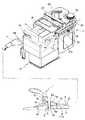
次に、本発明に係る自動排泄物処理装置の一実施形態に付いて、添付図面を参照しなが
ら説明する。図1は、本発明に係る自動排泄物処理装置を示す概略構成図であり、1は排
泄物を受ける排泄物受容手段、2は排泄物を収納する汚物タンクであり、排泄物受容手段
1と汚物タンク2とは第1の接続管3と第2の接続管4とにより接続するように構成して
ある。Next, an automatic excrement disposal apparatus according to an embodiment of the present invention will be described with reference to the accompanying drawings. FIG. 1 is a schematic configuration diagram showing an automatic excrement disposal apparatus according to the present invention, in which 1 is an excrement receiving means for receiving excrement, 2 is a filth tank for storing excrement, The
上記排泄物受容手段1は、例えば軟質合成樹脂等の軟質材で略U字形に形成されたパッ
ドから構成され、図示しないベッドに収容されている病人や怪我人、或いは寝たきり老人
等の股部分を前後に包囲して密着可能に装着できるようにしてある。この排泄物受容手段
1は、底部1aの内側に排泄物受け面が設けられ、この排泄物受け面の要所に尿検出用の
センサと便検出用のセンサとが配設されており、排泄物受け面は前方に傾斜して形成され
て排出口5に連通している。The excrement receiving means 1 is composed of a pad formed in a substantially U shape with a soft material such as a soft synthetic resin, for example, and a crotch portion of a sick person, an injured person, a bedridden elderly person, etc. accommodated in a bed (not shown). It is designed so that it can be attached in close contact with the front and back. The excrement receiving means 1 is provided with an excrement receiving surface inside the
前記第1の接続管3は、排泄物受容手段1の排出口5に外嵌挿着する接続端部3aを備
えると共に、前記第2の接続管4の端部に内嵌挿着する接続端部3bを備えている。この
第1の接続管3は、他の接続管例えば洗浄水供給管6、温風供給管7及び前記尿検出用の
センサと便検出用のセンサとにそれぞれ電気的に接続するための配線コード8と共に外管
9内に格納されている。温風供給管7は外管9に兼ねさせることが可能である。The
前記外管9の一方の端部にはプラグ10が設けられ、このプラグ10の内側に前記第1
の接続管3の接続端部3a、洗浄水供給管6の接続端部6a、温風供給管7の接続端部7
a、配線コード8の接続端子8aが間隔をあけてそれぞれ突出している。又、プラグ10
に対応させて前記排泄物受容手段1の前面下方部にはコネクタ12が設けられ、このコネ
クタ12は第1の接続管3の接続端部3aと接続する前記排出口5、洗浄水供給管6の接
続端部6aと接続する送水口14、温風供給管7の接続端部7aと接続する送風口15、
配線コード8の接続端子8aと電気的に接続する端子受け16がそれぞれ対応して突出し
ている。これにより、プラグ10をコネクタ12に嵌め合わせると上記各管の接続と配線
コード8の電気的接続とが同時に行えるようにしてある。これと同様に、外管9の他方の
端部にはプラグ11が設けられ、このプラグ11を駆動ユニット17側のコネクタ13に
嵌め合わせると各管の接続と配線コード8の電気的接続とが同時に行える。A plug 10 is provided at one end of the
a, the
Correspondingly, a
この場合は、図示は省略するが前記駆動ユニット17の内部に排泄物吸引手段と、洗浄
水供給手段と、温風供給手段と、制御装置とが配置されている。そして、駆動ユニット1
7の上部には前記第2の接続管4が水平に保持して固定され、この第2の接続管4の他方
の端部は前記汚物タンク2の接続口に挿入して接続されている。又、駆動ユニット17の
上部には通気管18が第2の接続管4と平行に位置して固定され、この通気管18の一方
の端部は前記排泄物吸引手段に接続され、他方の端部は汚水タンク2の気液分離用セパレ
ータ(図略)に接続されている。In this case, although not shown, excrement suction means, washing water supply means, hot air supply means, and a control device are arranged inside the
The second connecting
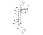
更に、駆動ユニット17の上部の両側部には直線状のガイドレール19が水平に対設さ
れ、このガイドレール19に沿って図1で左右方向に移動する移動枠20が摺動自在に嵌
合されている。そして、前記汚物タンク2は、上部に対設した張出片2aを移動枠20の
上面に係止することにより吊持状態で保持されている。21はロックハンドルであり、両
側のレバーの先端部がそれぞれガイドレールの上面要所に取り付けられたブラケット22
にピンで枢支され、このピンを軸として回動可能に形成されている。前記両側のレバーに
はそれぞれ略円弧状のロック片21aが設けられ、このロック片21aがそれぞれ移動枠
20に形成された長孔20a(図2)と、これに合致するようにしてガイドレール19に
形成された長孔19a(図2)とを貫通して嵌まり込んだ状態でロックされ、ロックハン
ドル21を回動してロック片21aを双方の長孔から抜いた状態でロックが解除されるよ
うにしてある。Further,
It is pivotally supported by a pin and is formed to be rotatable about this pin. Each of the levers on both sides is provided with a substantially arc-shaped
図2は、前記汚物タンク2と移動枠20の外観を示す斜視図であり、前記駆動ユニット
17に対向する面の上部に防臭手段23が設けられている。防臭手段23は例えばシャッ
タ部材24から構成され、このシャッタ部材24の上端の両側部はそれぞれピンを介して
汚物タンク2に枢支され、且つシャッタ部材24と汚物タンク2の間に戻しバネ25が設
けられている。これにより、シャッタ部材24は閉じた状態であり、前記第2の接続管4
を接続する接続口2bと、前記通気管18を接続する接続口2cとを閉塞している。FIG. 2 is a perspective view showing the appearance of the
The
この汚物タンク2を前記移動枠20に落とし込むと、前記のように両側の張出片2aが
それぞれ移動枠20の上面に受止されて吊持状態に保持される。この落とし込みの際に、
図3に仮想線で示すように前記シャッタ部材24は移動枠20に接触しながら、戻しバネ
25を徐々に伸ばして上向きに回転し、ほぼ水平状態となって移動枠20上に保持される
。これにより、シャッタ部材24は開状態となって前記接続口2b及び接続口2cを開放
する。シャッタ部材24の下端部には傾斜面24aを形成してあり、移動枠20との接触
時に当該傾斜面24aをガイドとしてシャッタ部材24が回転し易いようにしてある。When the
As shown by phantom lines in FIG. 3, the
この状態のまま、移動枠20を前記ガイドレール19に沿って移動すると、移動枠20
と共に汚物タンク2が前記駆動ユニット17に接近する。そして、前記ロックハンドル2
1を下向きに回転させてロック片21aを移動枠20の長孔20aに係合させると共に、
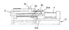
ロックハンドル21を更に回転させると移動枠20を強く引き寄せる。これにより、図4
に示すようにロックハンドル21はガイドレール19の前記長孔19aにも完全に係合し
てロック状態となり、同時に汚物タンク2と第2の接続管4及び通気管18との接続がな
される。尚、移動枠20には、図2に示すように第2の接続管4及び通気管18を通すた
めの通孔20bが設けられている。図5は、第2の接続管4と汚物タンク2の接続口2b
とが接続された状態を示す一部破断面図である。If the moving
At the same time, the
1 is rotated downward to engage the
When the lock handle 21 is further rotated, the moving
As shown in FIG. 4, the lock handle 21 is completely engaged with the
It is a partially broken sectional view which shows the state to which and were connected.
このように構成された自動排泄物処理装置は、前記排泄部受容手段1における排泄物検
出センサが排泄物を検出すると、その検出信号が駆動ユニット17の制御装置に入力され
、この制御装置から信号が出力されて洗浄水供給手段が作動し、洗浄水が洗浄水供給管6
を通って排泄物受容手段1に供給され、当該排泄物受容手段1を装着している装着人の局
部や尻部を洗浄する。一定時間経過後に洗浄水供給手段が停止し、制御装置から信号が出
力されて排泄物吸引手段が作動し、排泄物受容手段1内の排泄物を洗浄後の汚水と共に排
出口5から排出する。排出された汚物は、第1の接続管3を通って第2の接続管4内に流
入し、この第2の接続管4から汚物タンク2内に収納される。排泄物吸引手段の停止後に
、制御装置から信号が出力されて温風供給手段が作動し、温風が温風供給管7を通って排
泄物受容手段1に供給され、装着人の局部や尻部を乾かすと共に排泄物受容手段1内を乾
燥させる。この温風供給手段は一定時間作動した後停止する。In the automatic excrement disposal apparatus configured as described above, when the excrement detection sensor in the excretion part receiving means 1 detects excrement, the detection signal is input to the control device of the
Then, it is supplied to the excretion receiving means 1 and the local part and the buttocks of the wearer wearing the excretion receiving means 1 are washed. After a predetermined time elapses, the washing water supply means stops, a signal is output from the control device, the excrement suction means operates, and the excrement in the excretion receiving means 1 is discharged from the
汚物タンク2内に多量の汚物が溜まったら、前記ロックハンドル21を上向きに回転さ
せてロックを解除し、移動枠20をガイドレール19に沿って図1で右方向に移動させ、
汚物タンク2と前記第2の接続管4及び通気管18との接続を離す。この後、汚物タンク
2の上面に設けられている把手29(図1、図2)を起立させて手に持ち、汚物タンク2
を持ち上げて移動枠20から外す。When a large amount of filth accumulates in the
The connection between the
Is removed from the moving
汚物タンク2を持ち上げて前記シャッタ部材24が移動枠20から離れた時に、前記戻
しバネ25の復元力によってシャッタ部材24が下向きに回転して閉状態となり、前記接
続口2b及び接続口2cを自動的に閉塞する。これにより、汚物タンク2から悪臭が漏れ
出るのを抑えることができる。図6は、シャッタ部材24の閉状態を示す汚物タンクの側
面図である。When the
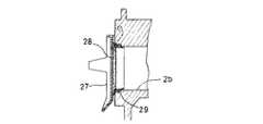
図7は、シャッタ部材の他の実施形態を示すもので、基本的な構成は前記シャッタ部材
24と同じであるが、シャッタ部材27の内側面(汚物タンク2の管接続口を塞ぐ面)に
パッキン28を取り付けたことが構成上相違している。この場合、図8に示すようにシャ
ッタ部材27が閉じると、汚物タンク2の管接続口がパッキン28により密閉されるため
、悪臭の漏れ出しをほぼ完全に防止することができる。特に第2の接続管4を接続する接
続口2bの開口端の内周面にもリング状のパッキン29を嵌着しておけば、シャッタ部材
27のパッキン28が接続口2bのパッキン29に密着することにより密着性を更に向上
させることができる。又、接続口2bのパッキン29は、図7のように第2の接続管4の
接続時においてその接続部分を密閉する機能を発揮する。更に、第2の接続管4を外す際
に、その端部の外周面を移動することで汚物を掻き取る機能も発揮する。FIG. 7 shows another embodiment of the shutter member. The basic configuration is the same as that of the
前記移動枠20から外した汚物タンク2は、例えばトイレまで運んでキャップ30を外
し汚物を排出する。この搬送中もシャッタ部材24の閉状態は保持されているので周囲に
悪臭を放出することはない。尚、駆動ユニット17側で露出した第1の接続管3の端部及
び通気管18の端部にもそれぞれ別途用意した適宜キャップ(図示せず)を被せるように
するとよい。The
図9は、前記キャップ30を着脱する汚物排出口31を示す断面図である。この汚物排
出口31は、外周面にネジ部31a(雄ネジ部)が設けられ、このネジ部31aは外周面
の上端からではなくほぼ中間部から下方に位置させて形成されている。これにより、汚物
排出口31の外周面において、その上端からネジ部31aの始端までの高さhの領域は無
ネジ部31bとなっている。又、汚物排出口31の内周面の上部には、上端に行くに連れ
て漸次縮径するテーパ面31cが形成されている。FIG. 9 is a cross-sectional view showing a
前記キャップ30は、内周面にネジ溝部30a(雌ネジ部)が設けられ、このネジ溝部
30aは内周面の下端からほぼ中間部に位置させて形成され、それより上部は無ネジ溝部
30bとなっている。これにより、図10に示すようにキャップ30を上記汚物排出口3
1に螺着する際に、キャップ30のネジ溝部30aは前記無ネジ部31bにガイドされて
そのまま下降して前記高さh分だけ嵌まり込み、この後ネジ部31aに螺合することによ
りキャップ30を汚物排出口31に螺着することができる。汚物排出口31のネジ部31
aが外周面の上端から始まっていると、キャップ30を螺合する際に嵌め難いことがある
が、先ず高さh分だけ落とし込んでから螺合する構成を採用することで、嵌め合わせを容
易にしたのである。又、キャップ30を外す時も、ネジ部31aの高さが低いために外し
易い利点がある。The
When screwed to 1, the
If a starts from the upper end of the outer peripheral surface, it may be difficult to fit when the
前記汚物排出口31の内周面の上部にはテーパ面31cを形成してあるため、図11に
示すように汚物排出口31から汚物を排出する際に、テーパ面31cが汚水切れの作用を
なす。これにより、汚物排出口31からの汚水の滴下を抑えることができ、汚物排出直後
においてトイレの周囲に汚水の一部が滴下して悪臭が漂うのを防ぐことができる。Since the tapered
汚物タンク2は、図1に示すようにセパレータ(図略)が内蔵されている上部と、汚物
を収納する下部タンクとがパッチン錠32によって着脱自在になっており、このパッチン
錠32を外せば汚物排出後に下部タンク内を洗浄することが可能である。As shown in FIG. 1, the
汚物排出後に、前記と同様に汚物タンク2を移動枠20に上から落とし込んで張出片2
aを係止させることで移動枠20に吊持状態で保持させることができる。この時、前記シ
ャッタ部材24は移動枠20により戻しバネ25に抗して上向きに回転させられ、接続口
2b及び接続口2cを露出させる。この状態を保持して汚物タンク2を移動枠20と共に
図1で左方に移動すると、第2の接続管4の端部が接続口2bに挿入すると共に通気管1
8の端部が接続口2cに挿入することでそれぞれ接続する。そして、前記ロックハンドル
21を回転させてロック片21aを、互いに合致している長孔(移動枠20の長孔20a
とガイドレール19の長孔19a)に差し込めば汚物タンク2を引き寄せた接続状態でロ
ックすることができる。After the filth is discharged, the
By locking a, the
8 end portions are connected to each other by being inserted into the connection port 2c. Then, the lock handle 21 is rotated so that the
And the
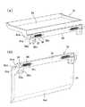
図12は、シャッタ部材の更に他の実施形態を示すもので、(a)はシャッタ部材32
が開いた状態での内面側から見た斜視図、(b)はシャッタ部材32が閉じた状態での内
面側から見た斜視図である。このシャッタ部材32は、前記汚物タンク2に固定される支
持部材33と、この支持部材33に枢支軸35を介して開閉自在に取り付けられる蓋板3
4とを備えている。FIG. 12 shows still another embodiment of the shutter member, and FIG.
The perspective view seen from the inner surface side in the state which opened, (b) is the perspective view seen from the inner surface side in the state which the
4 is provided.
上記支持部材33は細長い板状を呈しており、その両端部の下方に取付部33aが設け
られると共に、ねじ挿通用の孔33bがそれぞれ設けられ、又図13に示すように両端部
の内面(汚物タンク2に対向する面)には凹部33cが設けられ、この凹部33cに連通
する断面略半円状の通孔33dがそれぞれ設けられ、凹部33cの奥端面ににはバネ取付
孔33eがそれぞれ設けられている。The
支持部材33の凹部33cには前記枢支軸35が軸回転可能に嵌め込まれ、この枢支軸
35の縮径部35aは前記通孔33dを介して支持部材33の側面から突出させる。当該
縮径部35aの端部に、対向平面を有する断面非円形の係合部35bが設けられており、
この係合部35bを前記蓋板34の上部両端に設けた取付部34aの係合孔34bにそれ
ぞれ係合させる。この蓋板34の係合孔34bは、枢支軸35の係合部35bに対応させ
て設けたものであり、蓋体34と枢支軸35とが同時に回転するようにしてある。これに
より、支持部材33に対して蓋板34が枢支軸35を介して開閉自在に取り付けられる。The
The engaging
更に、支持部材33の両端部の凹部33c内に戻しバネ36が挿入され、その一端は前
記枢支軸35の縮径部35aと反対側の端部に形成されているバネ取付孔35cに挿着さ
れ、他端は凹部33cにおける前記バネ取付孔33eに挿着される。この戻しバネ36と
しては、捻じりコイルバネを使用することができ、この戻しバネ36によって蓋板34の
開閉動作が規制される。Further, a
このようにして一体化されたシャッタ部材32は、図14に示すように前記支持部材3
3における取付部33aのねじ挿通用の孔33bを利用して、支持部材33の両端部を前
記汚物タンク2にねじ37でそれぞれ固定することにより取り付けることができる。これ
により、支持部材33の内面は汚物タンク2の外面に密接して前記凹部33cは外から見
えなくなり、戻しバネ36も外から見えず外部に露出しない状態となる。又、蓋板34は
前記汚物タンク2の接続口2b及び2cを閉塞した閉状態であり、この閉状態は前記戻し
バネ36により保持される。このシャッタ部材32においても、図7に示すシャッタ部材
24と同様に内面側(この場合は、蓋板34の内面側)にパッキン(図略)を取り付けて
、汚物タンク2の接続口2b及び2cを密閉することが好ましい。The
3 can be attached by fixing both ends of the
このシャッタ部材32の動作は前記シャッタ部材と同じであり、前記汚物タンク2を移
動枠20に落とし込むと、前記のように両側の張出片2aがそれぞれ移動枠20の上面に
受止されて吊持状態に保持される。この落とし込みの際に、シャッタ部材32の蓋板34
は移動枠20に接触しながら、戻しバネ36を徐々に捻じりながら上向きに回転し、ほぼ
水平状態となって移動枠20上に保持される。これにより、シャッタ部材32は開状態と
なって前記接続口2b及び接続口2cを開放する。蓋板34の下端部には傾斜面34cを
形成してあり、移動枠20との接触時に当該傾斜面34cをガイドとして蓋板34が回転
し易いようにしてある。The operation of the
Is rotated upward while gradually twisting the
この状態のまま、移動枠20を前記ガイドレール19に沿って移動すると、移動枠20
と共に汚物タンク2が前記駆動ユニット17に接近する。そして、前記ロックハンドル2
1を下向きに回転させてロック片21aを移動枠20の長孔20aに係合させると共に、
ロックハンドル21を更に回転させると移動枠20を強く引き寄せる。これにより、ロッ
クハンドル21はガイドレール19の前記長孔19aにも完全に係合してロック状態とな
り、同時に汚物タンク2と第2の接続管4及び通気管18との接続がなされる。If the moving
At the same time, the
1 is rotated downward to engage the
When the lock handle 21 is further rotated, the moving
汚物タンク2内に多量の汚物が溜まったら、前記のようにロックハンドル21を上向き
に回転させてロックを解除し、移動枠20をガイドレール19に沿って移動させ、汚物タ
ンク2と前記第2の接続管4及び通気管18との接続を離す。この後、汚物タンク2の上
面に設けられている把手29を起立させて手に持ち、汚物タンク2を持ち上げて移動枠2
0から外す。When a large amount of filth accumulates in the
Remove from zero.
汚物タンク2を持ち上げて前記シャッタ部材32が移動枠20から離れた時に、前記戻
しバネ36の捻じり復元力によって蓋板34が下向きに回転して閉状態となり、前記接続
口2b及び接続口2cを自動的に閉塞する。これにより、汚物タンク2から悪臭が漏れ出
るのを抑えることができる。When the
戻しバネ36は、前記支持部材33の凹部33c内に収容されていて外部に露出してい
ない。このため、汚物タンク2を着脱する際又は汚物タンク2を持ち運びする際に、戻し
バネ36が看護人の衣服等に接触することは無く、きわめて清潔であると共に持ち運びが
安全にでき、かつ戻しバネ36に外力が加わって伸びたり外れたりするようなことはない
。The
本発明は、自力で歩けずにベッドに収容されている病人や怪我人、或いは寝たきり老人
等が使用する自動排泄物処理装置に適用することができ、汚物タンクを外しても接続口が
防臭手段として設けたシャッタ部材により閉塞されるため悪臭の漏出を防ぐことができ、
良好な環境を保つことができる。INDUSTRIAL APPLICABILITY The present invention can be applied to an automatic excrement disposal apparatus used by a sick person, an injured person, a bedridden elderly person or the like who is not allowed to walk on his own, and the connection port has a deodorizing means even when the filth tank is removed. Can be prevented from leaking offensive odor because it is blocked by the shutter member provided as,
A good environment can be maintained.
1 排泄物受容手段
2 汚物タンク
2b、2c 接続口
3 第1の接続管
4 第2の接続管
5 排出口
6 洗浄水供給管
7 温風供給管
8 配線コード
9 外管
10、11 プラグ
12、13 コネクタ
14 送水口
15 送風口
16 端子受け
17 駆動ユニット
18 通気管
19 ガイドレール
20 移動枠
21 ロックハンドル
22 ブラケット
23 防臭手段
24 シャッタ部材
25 戻しバネ
32 シャッタ部材
33 支持部材
33c 凹部
34 蓋板
35 枢支軸
36 戻しバネ
37 ねじDESCRIPTION OF SYMBOLS 1 Excrement receiving means 2
Claims (6)
Translated fromJapanese排泄物を収納する汚物タンクとが接続管によって接続された自動排泄物処理装置において
、前記汚物タンクと接続管との接続部に防臭手段を設けたことを特徴とする自動排泄物処
理装置。In the automatic waste disposal apparatus in which a waste receiving means attached to the crotch portion for receiving waste and a waste tank for storing waste sucked from the waste receiving means are connected by a connecting pipe, the waste tank An automatic excrement disposal apparatus, characterized in that a deodorizing means is provided at a connection portion between the connection pipe and the connection pipe.
特徴とする請求項1に記載の自動排泄物処理装置。2. The automatic excrement disposal apparatus according to claim 1, wherein the deodorizing means is composed of a shutter member provided in the filth tank.
れていることを特徴とする請求項2に記載の自動排泄物処理装置。The automatic excrement disposal apparatus according to claim 2, wherein the shutter member is formed to be openable and closable with respect to a pipe connection port provided in the filth tank.
管接続口に前記接続管が接続している時は開いており、前記接続管が外された時に前記戻
しバネを介して自動的に閉じることを特徴とする請求項3に記載の自動排泄物処理装置。The shutter member is attached to the waste tank via a return spring, and is open when the connection pipe is connected to a pipe connection port of the waste tank, and the return spring is opened when the connection pipe is removed. The automatic waste disposal apparatus according to claim 3, wherein the automatic waste disposal apparatus closes automatically.
を介して開閉自在に取り付けられる蓋板とを備え、前記支持部材の両端部における前記汚
物タンクに対向する面に凹部を設け、この凹部内に前記枢支軸を軸回転可能に嵌め込むと
共に、この枢支軸の一方の端部を支持部材の側方に突出させて前記蓋板の上部両側にそれ
ぞれ軸着し、前記枢支軸の他方の端部と前記凹部の端壁との間に戻しバネをそれぞれ取り
付けたことを特徴とする請求項4に記載の自動排泄物処理装置。The shutter member includes a support member fixed to the waste tank and a cover plate attached to the support member via a pivot shaft so as to be freely opened and closed, and faces the waste tank at both ends of the support member. A concave portion is provided on the surface, and the pivot shaft is fitted into the concave portion so as to be axially rotatable, and one end portion of the pivot shaft is protruded to the side of the support member to be respectively provided on both upper sides of the lid plate. The automatic excrement disposal apparatus according to claim 4, wherein a return spring is attached between the other end of the pivot shaft and the end wall of the recess.
いることを特徴とする請求項2ないし請求項5のいずれかに記載の自動排泄物処理装置。6. The automatic excrement disposal apparatus according to claim 2, wherein a packing is attached to a surface of the shutter member that closes a pipe connection port of the waste tank.
Priority Applications (1)
| Application Number | Priority Date | Filing Date | Title |
|---|---|---|---|
| JP2006258156AJP2007289638A (en) | 2006-03-29 | 2006-09-25 | Automatic excreta treating apparatus |
Applications Claiming Priority (2)
| Application Number | Priority Date | Filing Date | Title |
|---|---|---|---|
| JP2006092223 | 2006-03-29 | ||
| JP2006258156AJP2007289638A (en) | 2006-03-29 | 2006-09-25 | Automatic excreta treating apparatus |
Publications (1)
| Publication Number | Publication Date |
|---|---|
| JP2007289638Atrue JP2007289638A (en) | 2007-11-08 |
Family
ID=38760841
Family Applications (1)
| Application Number | Title | Priority Date | Filing Date |
|---|---|---|---|
| JP2006258156APendingJP2007289638A (en) | 2006-03-29 | 2006-09-25 | Automatic excreta treating apparatus |
Country Status (1)
| Country | Link |
|---|---|
| JP (1) | JP2007289638A (en) |
Cited By (9)
| Publication number | Priority date | Publication date | Assignee | Title |
|---|---|---|---|---|
| JP2012525906A (en)* | 2009-05-07 | 2012-10-25 | 株式会社キュラコ | Excrement disposal apparatus and method |
| US8771393B1 (en) | 2011-08-29 | 2014-07-08 | Exelis, Inc. | Integrated polar cap for a vacuum waste tank system |
| CN108577895A (en)* | 2018-03-19 | 2018-09-28 | 马奔腾 | A kind of routine urinalysis sample reception device |
| CN109248098A (en)* | 2018-11-23 | 2019-01-22 | 邓琴 | A kind of puerpera's vomitus holder |
| CN111449828A (en)* | 2019-01-18 | 2020-07-28 | 酷洁有限公司 | Backflow prevention device |
| US12310921B2 (en) | 2020-07-21 | 2025-05-27 | Icu Medical, Inc. | Fluid transfer devices and methods of use |
| US12333201B2 (en) | 2017-12-27 | 2025-06-17 | Icu Medical, Inc. | Synchronized display of screen content on networked devices |
| US12346879B2 (en) | 2011-08-19 | 2025-07-01 | Icu Medical, Inc. | Systems and methods for a graphical interface including a graphical representation of medical data |
| US12350233B2 (en) | 2021-12-10 | 2025-07-08 | Icu Medical, Inc. | Medical fluid compounding systems with coordinated flow control |
- 2006
- 2006-09-25JPJP2006258156Apatent/JP2007289638A/enactivePending
Cited By (12)
| Publication number | Priority date | Publication date | Assignee | Title |
|---|---|---|---|---|
| JP2012525906A (en)* | 2009-05-07 | 2012-10-25 | 株式会社キュラコ | Excrement disposal apparatus and method |
| US12346879B2 (en) | 2011-08-19 | 2025-07-01 | Icu Medical, Inc. | Systems and methods for a graphical interface including a graphical representation of medical data |
| US8771393B1 (en) | 2011-08-29 | 2014-07-08 | Exelis, Inc. | Integrated polar cap for a vacuum waste tank system |
| US12333201B2 (en) | 2017-12-27 | 2025-06-17 | Icu Medical, Inc. | Synchronized display of screen content on networked devices |
| CN108577895A (en)* | 2018-03-19 | 2018-09-28 | 马奔腾 | A kind of routine urinalysis sample reception device |
| CN108577895B (en)* | 2018-03-19 | 2021-02-19 | 白玉 | Urine conventional sample stays gets device |
| CN109248098A (en)* | 2018-11-23 | 2019-01-22 | 邓琴 | A kind of puerpera's vomitus holder |
| CN109248098B (en)* | 2018-11-23 | 2021-02-05 | 荣月华 | Vomitus container for lying-in woman |
| CN111449828A (en)* | 2019-01-18 | 2020-07-28 | 酷洁有限公司 | Backflow prevention device |
| JP2020116375A (en)* | 2019-01-18 | 2020-08-06 | キュラコ・インコーポレイテッドCURACO,Inc. | Backflow prevention device |
| US12310921B2 (en) | 2020-07-21 | 2025-05-27 | Icu Medical, Inc. | Fluid transfer devices and methods of use |
| US12350233B2 (en) | 2021-12-10 | 2025-07-08 | Icu Medical, Inc. | Medical fluid compounding systems with coordinated flow control |
Similar Documents
| Publication | Publication Date | Title |
|---|---|---|
| JP2007289638A (en) | Automatic excreta treating apparatus | |
| JP4643523B2 (en) | Automatic defecation processing device | |
| JP4119462B2 (en) | Automatic defecation processing device | |
| KR20190061457A (en) | Apparatus to remove foul odor for toilet | |
| JP2003153933A (en) | Nursing toilet system | |
| KR100777165B1 (en) | Toilet seat with a urinal for men | |
| KR101257204B1 (en) | Automatic operation toilet | |
| JP2007285070A (en) | Vacuum type toilet device | |
| KR100924812B1 (en) | Excretion processing device and processing method | |
| KR20180047315A (en) | Flush toilet having a separate urinal fow male | |
| CN110117982B (en) | Urinals and toilet facilities | |
| JP2002165821A (en) | Excreta disposer | |
| CN208563510U (en) | Urinal and the equipment that goes to the toilet | |
| KR101417576B1 (en) | Automatic excretion cleaner with improved connection structure of connecting pipe | |
| KR20180009299A (en) | Deodorizer for toilet seat | |
| JP2006026124A (en) | Excrement disposal device | |
| JP4467361B2 (en) | Excrement disposal apparatus and hose cleaning method for waste disposal apparatus | |
| JP2007167599A (en) | Small male urinal housing toilet seat | |
| CN107923171B (en) | Toilet deodorizer | |
| JP2017048553A (en) | Deodorization device and toilet bowl | |
| JP2007289637A (en) | Automatic excreta disposal apparatus | |
| JP2005334545A (en) | Excreta disposer | |
| JP2008025171A (en) | Toilet bowl | |
| JP7399506B2 (en) | Excrement treatment equipment and its cleaning method | |
| KR101544165B1 (en) | A Urinal Comprising Ammonia Removing Functionality |