JP2007287203A - Optical system drive unit - Google Patents
Optical system drive unitDownload PDFInfo
- Publication number
- JP2007287203A JP2007287203AJP2006110829AJP2006110829AJP2007287203AJP 2007287203 AJP2007287203 AJP 2007287203AJP 2006110829 AJP2006110829 AJP 2006110829AJP 2006110829 AJP2006110829 AJP 2006110829AJP 2007287203 AJP2007287203 AJP 2007287203A
- Authority
- JP
- Japan
- Prior art keywords
- carriage
- coil
- tracking direction
- frame
- objective lens
- Prior art date
- Legal status (The legal status is an assumption and is not a legal conclusion. Google has not performed a legal analysis and makes no representation as to the accuracy of the status listed.)
- Pending
Links
- 230000003287optical effectEffects0.000titleclaimsabstractdescription18
- 238000004804windingMethods0.000description6
- 238000005452bendingMethods0.000description1
- 238000010586diagramMethods0.000description1
Images


Classifications
- G—PHYSICS
- G11—INFORMATION STORAGE
- G11B—INFORMATION STORAGE BASED ON RELATIVE MOVEMENT BETWEEN RECORD CARRIER AND TRANSDUCER
- G11B7/00—Recording or reproducing by optical means, e.g. recording using a thermal beam of optical radiation by modifying optical properties or the physical structure, reproducing using an optical beam at lower power by sensing optical properties; Record carriers therefor
- G11B7/08—Disposition or mounting of heads or light sources relatively to record carriers
- G11B7/085—Disposition or mounting of heads or light sources relatively to record carriers with provision for moving the light beam into, or out of, its operative position or across tracks, otherwise than during the transducing operation, e.g. for adjustment or preliminary positioning or track change or selection
- G11B7/0857—Arrangements for mechanically moving the whole head
- G11B7/08582—Sled-type positioners
- G—PHYSICS
- G11—INFORMATION STORAGE
- G11B—INFORMATION STORAGE BASED ON RELATIVE MOVEMENT BETWEEN RECORD CARRIER AND TRANSDUCER
- G11B7/00—Recording or reproducing by optical means, e.g. recording using a thermal beam of optical radiation by modifying optical properties or the physical structure, reproducing using an optical beam at lower power by sensing optical properties; Record carriers therefor
- G11B7/08—Disposition or mounting of heads or light sources relatively to record carriers
- G11B7/09—Disposition or mounting of heads or light sources relatively to record carriers with provision for moving the light beam or focus plane for the purpose of maintaining alignment of the light beam relative to the record carrier during transducing operation, e.g. to compensate for surface irregularities of the latter or for track following
- G11B7/0925—Electromechanical actuators for lens positioning
- G11B7/0929—Electromechanical actuators for lens positioning for tracking only
- G—PHYSICS
- G11—INFORMATION STORAGE
- G11B—INFORMATION STORAGE BASED ON RELATIVE MOVEMENT BETWEEN RECORD CARRIER AND TRANSDUCER
- G11B7/00—Recording or reproducing by optical means, e.g. recording using a thermal beam of optical radiation by modifying optical properties or the physical structure, reproducing using an optical beam at lower power by sensing optical properties; Record carriers therefor
- G11B7/08—Disposition or mounting of heads or light sources relatively to record carriers
- G11B7/09—Disposition or mounting of heads or light sources relatively to record carriers with provision for moving the light beam or focus plane for the purpose of maintaining alignment of the light beam relative to the record carrier during transducing operation, e.g. to compensate for surface irregularities of the latter or for track following
- G11B7/0925—Electromechanical actuators for lens positioning
- G11B7/0935—Details of the moving parts
Landscapes
- Optical Recording Or Reproduction (AREA)
- Moving Of The Head For Recording And Reproducing By Optical Means (AREA)
Abstract
Description
Translated fromJapanese本発明は、光学系駆動装置に係り、特に、CD、DVD等を読み取るピックアップ装置に搭載される光学系駆動装置に関する。 The present invention relates to an optical system drive device, and more particularly to an optical system drive device mounted on a pickup device that reads a CD, a DVD, or the like.
ピックアップ装置に搭載されている光学系駆動装置は、電磁力によって対物レンズをトラッキング方向に移動させるようになっている(例えば特許文献1参照)。具体的には、光学系駆動装置100には、図4に示すように対物レンズ101と、対物レンズ101を搭載するキャリッジ102とが設けられている。キャリッジ102は、一対のガイド103によってスライド自在に支持されている。ガイド103はトラッキング方向に沿うように配置されている。キャリッジ102がガイド103に沿ってスライドすると、対物レンズ101がトラッキング方向に沿って移動することになる。 The optical system driving device mounted on the pickup device moves the objective lens in the tracking direction by electromagnetic force (see, for example, Patent Document 1). Specifically, the optical
また、キャリッジ102の両側面にはそれぞれコイル104が、巻き方向がトラッキング方向に沿うように取り付けられている。コイル104は、ガイド103と平行な内ヨーク105が挿入されている。内ヨーク105の外側には、外ヨーク106が内ヨーク105とともに枠を形成するように配置されている。外ヨーク106の内側には、当該内ヨーク105に沿って棒状の永久磁石107が配置されている。 In addition,
そして、コイル104に電流が流れると、永久磁石107との電磁力が発生することになる。この電磁力によって、キャリッジ102がガイド103に沿って移動し、対物レンズ101をトラッキング方向に移動させることになる。また、コイルに流れる電流を制御すると、対物レンズ101の位置制御が実行されることになっている。
ところで、巻き方向がトラッキング方向に沿うようにコイル104がキャリッジ102に固定されていると、一番外側に巻かれたコイルの一面のみが固定されるために強度が不安定となっている。特に、コイル104は、内ヨーク105を囲う構成なので強度を保ちにくい。これらのことから、移動時にはコイル104自体が共振しやすくなっていて、共振してしまうと対物レンズの位置制御が不安定になってしまう。 By the way, when the
本発明の課題は、コイルの共振を抑制して、対物レンズの位置制御の正確性を高めることである。 The subject of this invention is suppressing the resonance of a coil and improving the precision of position control of an objective lens.
請求項1記載の発明における光学系駆動装置は、
対物レンズを搭載するキャリッジと、
前記キャリッジをスライド自在に支持して、トラッキング方向に案内するガイドと、
前記キャリッジの両側部に取り付けられて、前記トラッキング方向に直交する方向に巻かれた少なくとも一対のコイルと、
前記キャリッジを挟んで前記コイルに対向する少なくとも一対の磁石部とを備え、
前記一対の磁石部は、それぞれ2つの磁極が前記トラッキング方向に直交する方向に沿うように配置された永久磁石を有し、
前記2つの磁極は互いに反対向きであることを特徴としている。The optical system driving device according to the invention of
A carriage carrying an objective lens;
A guide that slidably supports the carriage and guides it in the tracking direction;
At least a pair of coils attached to both sides of the carriage and wound in a direction orthogonal to the tracking direction;
And at least a pair of magnet portions facing the coil across the carriage,
Each of the pair of magnet portions includes permanent magnets arranged such that two magnetic poles are along a direction perpendicular to the tracking direction,
The two magnetic poles are opposite to each other.
請求項2記載の発明は、請求項1記載の光学系駆動装置において、
前記永久磁石及び前記ガイドを保持するフレームと、
前記フレームをスライド自在に支持して、前記トラッキング方向に案内するフレーム用ガイドと、
前記フレームに係合して、当該フレームを前記トラッキング方向に移動させる送り機構とを備えることを特徴としている。According to a second aspect of the present invention, in the optical system driving device according to the first aspect,
A frame for holding the permanent magnet and the guide;
A frame guide that supports the frame slidably and guides the frame in the tracking direction;
And a feed mechanism that engages with the frame and moves the frame in the tracking direction.
本発明によれば、キャリッジの両側部に、トラッキング方向に直交する方向に巻かれたコイルが取り付けられているので、キャリッジの移動方向(トラッキング方向)とコイルの巻き方向とが直交することになる。コイルの巻き方向とキャリッジの移動方向とが同じ方向であると、上記したように固定面積が小さいためにコイルが共振しやすい状態であるが、本発明では巻き方向と移動方向とが直交するようにコイルがキャリッジに取り付けられているので、コイルの基端側で巻かれている複数層の線材がキャリッジに固定されることになり、前者の場合と比較してもコイル自体がたわみにくくなる。このように、コイル全体に対して固定に用いられる面積割合が増加されることと、たわみにくくなることから、コイルの共振を抑制することができる。そして、キャリッジを挟んでコイルに対向する一対の磁石部は、それぞれ2つの磁極が前記トラッキング方向に直交する方向に沿うように配置された永久磁石を有していて、この2つの磁極が反対向きであるので、コイルに電流を付与すると、コイルと磁石部との間に電磁力が作用することになって、キャリッジをトラッキング方向に移動させることができる。つまり、電流量を調整すれば対物レンズの位置制御も実行することができるのである。このように、コイルがトラッキング方向に直交する方向に巻かれていても、対物レンズの位置制御ができるので、従来よりもコイルの安定性の高まった正確な対物レンズの位置制御が可能となる。 According to the present invention, since the coils wound in the direction orthogonal to the tracking direction are attached to both sides of the carriage, the moving direction of the carriage (tracking direction) and the winding direction of the coil are orthogonal. . If the winding direction of the coil and the moving direction of the carriage are the same direction, the coil is likely to resonate because the fixed area is small as described above. However, in the present invention, the winding direction and the moving direction are orthogonal to each other. Since the coil is attached to the carriage, a plurality of layers of wire wound around the base end side of the coil are fixed to the carriage, and the coil itself is less likely to bend than in the former case. Thus, since the area ratio used for fixation with respect to the whole coil is increased and bending becomes difficult, resonance of the coil can be suppressed. Each of the pair of magnet portions facing the coil across the carriage has permanent magnets arranged so that the two magnetic poles are along the direction orthogonal to the tracking direction, and the two magnetic poles face in opposite directions. Therefore, when a current is applied to the coil, an electromagnetic force acts between the coil and the magnet portion, and the carriage can be moved in the tracking direction. That is, the position control of the objective lens can be executed by adjusting the amount of current. As described above, since the position of the objective lens can be controlled even when the coil is wound in the direction orthogonal to the tracking direction, it is possible to accurately control the position of the objective lens with higher stability of the coil than in the prior art.
また、永久磁石及びガイドを保持するフレームは、送り機構によってトラッキング方向に移動するので、移動範囲が長くなる。これにより上記のトラッキング方向に直交する方向に沿って巻かれたコイルと、永久磁石とではカバーしきれない範囲でも、フレームを移動させることができる。したがって、トラッキング移動範囲の全域にわたって対物レンズの位置制御が可能となる。そして、対物レンズのトラッキング方向に対する大まかな位置調整はフレームを移動させて、微調整は対物レンズ自体を移動させるという2段階で実行することが可能となる。 Further, since the frame holding the permanent magnet and the guide is moved in the tracking direction by the feed mechanism, the moving range becomes long. Accordingly, the frame can be moved even in a range that cannot be covered by the coil wound along the direction orthogonal to the tracking direction and the permanent magnet. Therefore, the position of the objective lens can be controlled over the entire tracking movement range. Then, rough position adjustment of the objective lens with respect to the tracking direction can be performed in two stages, ie, the frame is moved, and fine adjustment is performed by moving the objective lens itself.
以下、本実施形態における光学系駆動装置について図を参照にして説明する。図1は光学系駆動装置1の概略構成を表す斜視図である。この図1に示すように、光学系駆動装置1には、対物レンズ2の位置を微調整する第1移動機構3と、第1移動機構3による微調整前に、トラッキング方向Aの移動範囲の全域にわたって対物レンズ2を移動させる第2移動機構4と、第1移動機構3及び第2移動機構3を制御する制御部(図示省略)が設けられている。 Hereinafter, the optical system driving apparatus in the present embodiment will be described with reference to the drawings. FIG. 1 is a perspective view illustrating a schematic configuration of the optical
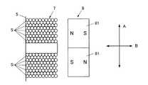
図2は第1移動機構3の概略構成を表す斜視図である。この図2に示すように、第1移動機構3には、対物レンズ2を搭載するキャリッジ5と、キャリッジ5をスライド自在に支持して、トラッキング方向Aに案内する一対のガイド6と、キャリッジ5の両側部に取り付けられた一対のコイル7と、キャリッジ5を挟んでコイル7に対向する一対の磁石部8とが設けられている。 FIG. 2 is a perspective view illustrating a schematic configuration of the
図3は、コイル7と磁石部8との位置関係を表す説明図である。この図3に示すように一対の磁石部8は、それぞれ2つの磁極がトラッキング方向Aに直交する方向Bに沿うように配置された少なくとも一対の永久磁石81を有している。この一対の永久磁石81の2つの磁極は互いに反対向きとなっている。また、コイル7も、トラッキング方向Aに直交する方向Bに沿って巻かれている。このように、コイル7が巻かれていると、コイル9の基端側で巻かれている複数層の線材Sがキャリッジ5に固定されることになる。
そして、コイル7に電流が流れると、コイル7に電磁力が発生し、当該電磁力によりトラッキング方向Aに沿ってコイル7が移動することになる。この移動に伴って、キャリッジ5がガイド6に沿って移動し、対物レンズ2の位置制御が可能となる。FIG. 3 is an explanatory diagram showing the positional relationship between the
When a current flows through the
第2移動機構4には、図1に示すように第1移動機構3の磁石部8及びガイド6を保持するフレーム9と、フレーム9をスライド自在に支持して、トラッキング方向Aに案内するフレーム用ガイド10と、フレーム9に係合して、当該フレーム9をトラッキング方向Aに移動させる送り機構11とが設けられている。 As shown in FIG. 1, the second moving mechanism 4 includes a frame 9 that holds the
送り機構11には、トラッキング方向Aに沿って複数の歯(図示省略)が形成されている連結部12がフレーム9の一側部に固定されて設けられている。また、送り機構11には、トラッキング方向Aに沿って配置されて、連結部12の歯に噛合するリードスクリュー13と、当該リードスクリュー13を回転させるモータ14とが設けられている。モータ14がリードスクリュー13を回転させることで、連結部12を介してフレーム9をトラッキング方向Aに移動させるようになっている。リードスクリュー13の長さは少なくとも対物レンズ2の移動範囲以上に設定されている。これにより、対物レンズ2の移動範囲内をフレーム9がフレーム用ガイド10に沿ってトラッキング方向Aに移動することができ、対物レンズ2の位置制御が可能となる。 The
次に、本実施形態の作用について説明する。
対物レンズ2の位置制御時においては、制御部はまず第2移動機構4により対物レンズ2を移動させる。この際、制御部は、モータ14を制御して、リードスクリュー13を回転させて、フレーム9をトラッキング方向Aに移動させる。その後、制御部はフレーム9が所定のトラッキング位置近傍で停止するように、モータ14を停止して、第2移動機構4による対物レンズ2の移動を終了する。Next, the operation of this embodiment will be described.
When the position of the
その後、制御部は第1移動機構3により対物レンズ2を移動させる。この際、制御部は、コイル7に対して所定の電流を付与する。これにより、コイル7と磁石部8との間に電磁力が作用し、当該力によってキャリッジ5がガイド6に沿ってトラッキング方向Aに移動する。その後、制御部は、対物レンズ2がディスク上の所定位置を追従するようにコイル7に対して電流を付与して、第1移動機構3による対物レンズ2の移動を実行する。 Thereafter, the control unit moves the
以上のように、本実施形態によれば、キャリッジ5の両側部に、トラッキング方向Aに直交する方向Bに巻かれたコイル7が取り付けられているので、トラッキング方向Aとコイル7の巻き方向とが直交することになる。このようにコイル7がキャリッジ5に取り付けられていれば、コイル7の基端側で巻かれている複数層の線材Sがキャリッジ5に固定されることになるので、コイル7自体がたわみにくくなり強度が増す。このように、コイル7全体に対して固定に用いられる面積割合が増加されることと、強度が増すことから、コイル7の共振を抑制することができる。したがって、コイル7の安定性を維持しやすくなるので、対物レンズ2の位置制御の正確性が高められることになる。 As described above, according to the present embodiment, the
そして、第2移動機構4の送り機構11によってフレーム9がトラッキング方向Aに移動されるので、対物レンズ2のトラッキング位置が大まかに調整されることになる。この第2移動機構4の位置調整後に、第1移動機構3のコイル7と磁石部8との電磁力によってキャリッジ5がトラッキング方向に移動することで、対物レンズのトラッキング位置が微調整されている。
なお、本発明は上記実施の形態に限らず適宜変更可能であるのは勿論である。Then, since the frame 9 is moved in the tracking direction A by the
It is needless to say that the present invention is not limited to the above embodiment and can be modified as appropriate.
1 光学系駆動装置
2 対物レンズ
3 第1移動機構
4 第2移動機構
5 キャリッジ
6 ガイド
7 コイル
8 永久磁石
9 フレーム
10 フレーム用ガイド
11 送り機構
12 連結部
13 リードスクリュー
14 モータ
A トラッキング方向
B 直交する方向
S 線材DESCRIPTION OF
Claims (2)
Translated fromJapanese前記キャリッジをスライド自在に支持して、トラッキング方向に案内するガイドと、
前記キャリッジの両側部に取り付けられて、前記トラッキング方向に直交する方向に巻かれた少なくとも一対のコイルと、
前記キャリッジを挟んで前記コイルに対向する少なくとも一対の磁石部とを備え、
前記一対の磁石部は、それぞれ2つの磁極が前記トラッキング方向に直交する方向に沿うように配置された永久磁石を有し、
前記2つの磁極は互いに反対向きであることを特徴とする光学系駆動装置。A carriage carrying an objective lens;
A guide that slidably supports the carriage and guides it in the tracking direction;
At least a pair of coils attached to both sides of the carriage and wound in a direction perpendicular to the tracking direction;
And at least a pair of magnet portions facing the coil across the carriage,
Each of the pair of magnet portions includes permanent magnets arranged such that two magnetic poles are along a direction perpendicular to the tracking direction,
The optical system driving apparatus according to claim 1, wherein the two magnetic poles are opposite to each other.
前記永久磁石及び前記ガイドを保持するフレームと、
前記フレームをスライド自在に支持して、前記トラッキング方向に案内するフレーム用ガイドと、
前記フレームに係合して、当該フレームを前記トラッキング方向に移動させる移動機構とを備えることを特徴とする光学系駆動装置。The optical system driving device according to claim 1,
A frame for holding the permanent magnet and the guide;
A frame guide that supports the frame slidably and guides the frame in the tracking direction;
An optical system driving device comprising: a moving mechanism that engages with the frame and moves the frame in the tracking direction.
Priority Applications (2)
| Application Number | Priority Date | Filing Date | Title |
|---|---|---|---|
| JP2006110829AJP2007287203A (en) | 2006-04-13 | 2006-04-13 | Optical system drive unit |
| US11/786,533US20070242573A1 (en) | 2006-04-13 | 2007-04-12 | Optical system driving device |
Applications Claiming Priority (1)
| Application Number | Priority Date | Filing Date | Title |
|---|---|---|---|
| JP2006110829AJP2007287203A (en) | 2006-04-13 | 2006-04-13 | Optical system drive unit |
Publications (1)
| Publication Number | Publication Date |
|---|---|
| JP2007287203Atrue JP2007287203A (en) | 2007-11-01 |
Family
ID=38604728
Family Applications (1)
| Application Number | Title | Priority Date | Filing Date |
|---|---|---|---|
| JP2006110829APendingJP2007287203A (en) | 2006-04-13 | 2006-04-13 | Optical system drive unit |
Country Status (2)
| Country | Link |
|---|---|
| US (1) | US20070242573A1 (en) |
| JP (1) | JP2007287203A (en) |
Citations (6)
| Publication number | Priority date | Publication date | Assignee | Title |
|---|---|---|---|---|
| JPS58179635U (en)* | 1982-05-25 | 1983-12-01 | 株式会社三協精機製作所 | Pickup objective lens drive device |
| JPS59110046A (en)* | 1982-12-14 | 1984-06-25 | Ricoh Co Ltd | Optical disk positioner device |
| JPS60127629U (en)* | 1984-01-31 | 1985-08-27 | 三洋電機株式会社 | Objective lens drive device |
| JPS6134623U (en)* | 1984-08-04 | 1986-03-03 | ソニー株式会社 | 2-axis drive device |
| JP2003123291A (en)* | 2001-10-16 | 2003-04-25 | Olympus Optical Co Ltd | Actuator for optical element |
| JP2004110997A (en)* | 2002-09-20 | 2004-04-08 | Ricoh Co Ltd | Lens drive device, optical pickup and optical disk device |
Family Cites Families (4)
| Publication number | Priority date | Publication date | Assignee | Title |
|---|---|---|---|---|
| US5265079A (en)* | 1991-02-15 | 1993-11-23 | Applied Magnetics Corporation | Seek actuator for optical recording |
| JP3895471B2 (en)* | 1998-07-17 | 2007-03-22 | 富士通株式会社 | Lens actuator |
| KR100522232B1 (en)* | 2003-12-24 | 2005-10-17 | 엘지전자 주식회사 | Optical pick-up actuator of slim type |
| JPWO2005112012A1 (en)* | 2004-05-14 | 2008-03-27 | ソニー株式会社 | Optical pickup and optical disk device |
- 2006
- 2006-04-13JPJP2006110829Apatent/JP2007287203A/enactivePending
- 2007
- 2007-04-12USUS11/786,533patent/US20070242573A1/ennot_activeAbandoned
Patent Citations (6)
| Publication number | Priority date | Publication date | Assignee | Title |
|---|---|---|---|---|
| JPS58179635U (en)* | 1982-05-25 | 1983-12-01 | 株式会社三協精機製作所 | Pickup objective lens drive device |
| JPS59110046A (en)* | 1982-12-14 | 1984-06-25 | Ricoh Co Ltd | Optical disk positioner device |
| JPS60127629U (en)* | 1984-01-31 | 1985-08-27 | 三洋電機株式会社 | Objective lens drive device |
| JPS6134623U (en)* | 1984-08-04 | 1986-03-03 | ソニー株式会社 | 2-axis drive device |
| JP2003123291A (en)* | 2001-10-16 | 2003-04-25 | Olympus Optical Co Ltd | Actuator for optical element |
| JP2004110997A (en)* | 2002-09-20 | 2004-04-08 | Ricoh Co Ltd | Lens drive device, optical pickup and optical disk device |
Also Published As
| Publication number | Publication date |
|---|---|
| US20070242573A1 (en) | 2007-10-18 |
Similar Documents
| Publication | Publication Date | Title |
|---|---|---|
| JP6507384B2 (en) | Lens drive device, camera device and electronic device | |
| US20090195878A1 (en) | Linear swing actuator | |
| CN111868622A (en) | Lens position adjustment device, camera module, information device, and camera driving method | |
| CN1501414A (en) | Operating device, manufacturing method of operating device, and opening and closing device having the operating device | |
| JP2015041096A (en) | Lens holder, lens driving device, camera device and electronic device | |
| WO2007116505A1 (en) | Linear motor | |
| JP5932295B2 (en) | LENS DRIVE UNIT, LENS DEVICE HAVING THE SAME, AND IMAGING DEVICE | |
| WO2015048928A1 (en) | Lens driving apparatus | |
| JP2006259032A (en) | Lens driving device | |
| JP2009230025A (en) | Coil drive unit, blur correction mechanism and imaging apparatus | |
| JP2007287203A (en) | Optical system drive unit | |
| JP5431295B2 (en) | XY stage | |
| JP2007199253A (en) | Lens driving apparatus, and manufacturing method of coil body used for lens driving apparatus | |
| JP2001148398A (en) | Xy stage | |
| JP2013164580A (en) | Zoom lens barrel | |
| JP2006121829A (en) | Drive device and optical apparatus | |
| US10170971B1 (en) | Dual pole dual bucking magnet linear actuator | |
| US20070274168A1 (en) | Optical pickup | |
| JP4036207B2 (en) | XY stage | |
| JPH1124125A (en) | Optical equipment | |
| JP2011075674A (en) | Lens barrel and imaging apparatus | |
| JP7023668B2 (en) | Lens barrel | |
| JP2007334978A (en) | Optical system driving device | |
| JP2006220776A (en) | Drive unit and lens drive unit | |
| JP4389123B2 (en) | Anti-vibration lens device |
Legal Events
| Date | Code | Title | Description |
|---|---|---|---|
| A621 | Written request for application examination | Free format text:JAPANESE INTERMEDIATE CODE: A621 Effective date:20090309 | |
| A977 | Report on retrieval | Free format text:JAPANESE INTERMEDIATE CODE: A971007 Effective date:20100415 | |
| A131 | Notification of reasons for refusal | Free format text:JAPANESE INTERMEDIATE CODE: A131 Effective date:20100420 | |
| A02 | Decision of refusal | Free format text:JAPANESE INTERMEDIATE CODE: A02 Effective date:20100817 |