JP2007286652A - Liquid crystal display - Google Patents
Liquid crystal displayDownload PDFInfo
- Publication number
- JP2007286652A JP2007286652AJP2007207261AJP2007207261AJP2007286652AJP 2007286652 AJP2007286652 AJP 2007286652AJP 2007207261 AJP2007207261 AJP 2007207261AJP 2007207261 AJP2007207261 AJP 2007207261AJP 2007286652 AJP2007286652 AJP 2007286652A
- Authority
- JP
- Japan
- Prior art keywords
- liquid crystal
- light
- crystal display
- polarization
- selective reflection
- Prior art date
- Legal status (The legal status is an assumption and is not a legal conclusion. Google has not performed a legal analysis and makes no representation as to the accuracy of the status listed.)
- Granted
Links
Images


Landscapes
- Liquid Crystal (AREA)
Abstract
Translated fromJapaneseDescription
Translated fromJapanese本発明は、液晶表示装置に関する。より詳しくは、強い周囲光下でも、視認性に優れた透過型液晶表示装置に関する。 The present invention relates to a liquid crystal display device. More specifically, the present invention relates to a transmissive liquid crystal display device having excellent visibility even under strong ambient light.
近年、数ある表示媒体の中でも、液晶を用いた液晶表示装置(Liquid Crystal Display ;LCD)は、低消費電力で表示が可能であるために最も実用化が進んでいる。この液晶表示装置の表示モード及び駆動方法として、単純マトリクス方式及びアクティブマトリクス方式の2方式が提案されている。一方、情報のマルチメディア化が進むにつれ、ディスプレイの高解像度化、高コントラスト化、多諧調(マルチカラー、フルカラー)化及び高視野角化が要求されるようになっている。このような要求に対し、単純マトリクス方式では対応が困難であると考えられる。そこで、個々の画素にスイッチング素子(アクティブ素子)を設けて、駆動可能な走査線電極の本数を増加させるアクティブマトリクス方式が提案されている。 In recent years, among many display media, a liquid crystal display (LCD) using liquid crystal has been most practically used because it can display with low power consumption. As a display mode and a driving method of this liquid crystal display device, two methods of a simple matrix method and an active matrix method have been proposed. On the other hand, as information becomes more and more multimedia, there is a demand for higher resolution, higher contrast, multi-tone (multicolor, full color) and higher viewing angle of the display. It is considered that it is difficult to cope with such a demand with the simple matrix method. In view of this, an active matrix system has been proposed in which switching elements (active elements) are provided in individual pixels to increase the number of scan line electrodes that can be driven.
このアクティブマトリクス方式の技術により、ディスプレイの高解像度化、高コントラスト化、多諧調化及び高視野角化が達成されつつある。アクティブマトリクス方式の液晶表示装置では、マトリクス状に設けられた画素電極と、該画素電極の近傍を通る走査線とが、スイッチング素子を介して電気的に接続された構成になっている。このスイッチング素子としては、2端子の非線形素子と3端子の非線形素子とがあり、現在採用されているスイッチング素子の代表格は、3端子素子の薄膜トランジスタ(Thin Film Transistor; TFT)である。 With this active matrix system technology, higher resolution, higher contrast, higher gradation, and higher viewing angle are being achieved. In an active matrix liquid crystal display device, a pixel electrode provided in a matrix and a scanning line passing through the vicinity of the pixel electrode are electrically connected via a switching element. The switching element includes a two-terminal nonlinear element and a three-terminal nonlinear element. A typical example of a switching element currently employed is a three-terminal thin film transistor (TFT).
また、近年、このようなアクティブマトリクス方式の液晶表示装置は、携帯電話等に代表されるモバイル機器に急速に普及している。 In recent years, such an active matrix liquid crystal display device has been rapidly spread in mobile devices such as mobile phones.
従来の透過型液晶表示装置は、液晶表示パネルの裏面にバックライトユニットを配置して透過表示を行っている。この方法は、室内など周囲光が比較的弱い環境下では、良好な画面表示を得ることができる。しかしながら、屋外や窓際などの直射日光が当たる、周囲光が強い環境下では、液晶表示パネルの表面や内部配線で周囲光が反射する。この反射光の光量はバックライトユニットから出射され液晶パネルを透過する光の光量を上回るため、実質的には周囲光の強い環境下で画面表示を確認すること(良好な視認性を得ること)は不可能であった。 A conventional transmissive liquid crystal display device performs transmissive display by arranging a backlight unit on the back surface of a liquid crystal display panel. This method can provide a good screen display under an environment where ambient light is relatively weak, such as indoors. However, ambient light is reflected by the surface of the liquid crystal display panel and the internal wiring in an environment where strong ambient light is exposed to direct sunlight such as outdoors or near a window. Since the amount of reflected light exceeds the amount of light emitted from the backlight unit and transmitted through the liquid crystal panel, the screen display should be checked in an environment with strong ambient light (to obtain good visibility). Was impossible.
そこで、周囲光の強い環境下においても良好な視認性を得ることができる技術として、反射型及び半透過型液晶表示装置が開発されてきた。この反射型及び半透過型液晶表示装置は、周囲光を液晶表示パネルの内部で反射し画面表示を行うための反射部(反射板)を有している。このような構造では、明るさは確保することができるが色純度は低下する。また、反射部に対応するカラーフィルター濃度を高くすると、明るさが不足する。このように反射部を用いた表示では、実質的に美しい画像表示を実現することは不可能であった。 In view of this, reflective and transflective liquid crystal display devices have been developed as techniques that can provide good visibility even in an environment with strong ambient light. The reflective and transflective liquid crystal display devices have a reflecting portion (reflecting plate) for performing screen display by reflecting ambient light inside the liquid crystal display panel. With such a structure, brightness can be ensured, but color purity decreases. Further, when the color filter density corresponding to the reflection portion is increased, the brightness is insufficient. Thus, it has been impossible to realize a substantially beautiful image display with the display using the reflection portion.
これに対して、例えば、特許文献1(以下、従来例1とする)または特許文献2(以下、従来例2とする)には、透過型液晶表示装置の裏面に設けられた導光板に外部光(周囲光)を集める手段を備えた集光機構付液晶表示装置が開示されている。これらの特許文献に開示されている液晶表示装置は導光板の端部にレンズ形状の集光部(採光部)を形成している。 On the other hand, for example, in Patent Document 1 (hereinafter referred to as Conventional Example 1) or Patent Document 2 (hereinafter referred to as Conventional Example 2), the light guide plate provided on the back surface of the transmissive liquid crystal display device is externally provided. A liquid crystal display device with a condensing mechanism having means for collecting light (ambient light) is disclosed. In the liquid crystal display devices disclosed in these patent documents, a lens-shaped condensing part (lighting part) is formed at the end of the light guide plate.
従来例1の液晶表示装置は、楔形の集光部である第1の照光部と、楔形の光源部である第2の照光部とが、互いに厚みを補完する形で、LCDパネルとともに重ね合わされた構成になっている。一方、従来例2の液晶表示装置は、LCDの背後に導光部が設けられ、この導光部と光路を接続する集光部が設けられている。導光部には、LCDへの光射出面及び集光部からの光導入口を除き、周囲に鏡面が形成されている。これら従来例1及び従来例2のいずれの液晶表示装置でも、上記集光部にて集光された外部光は、導光部(照光部)に導かれて乱反射されて、平面光源としてLCDへ照射される。 In the liquid crystal display device of Conventional Example 1, the first illuminating unit that is a wedge-shaped light condensing unit and the second illuminating unit that is a wedge-shaped light source unit are overlapped with the LCD panel so as to complement each other. It has a configuration. On the other hand, in the liquid crystal display device of Conventional Example 2, a light guide unit is provided behind the LCD, and a light collecting unit that connects the light guide unit and the optical path is provided. The light guide part has a mirror surface around it except for the light exit surface to the LCD and the light entrance from the light collecting part. In any of the liquid crystal display devices of the conventional example 1 and the conventional example 2, the external light collected by the light collecting unit is guided to the light guide unit (illuminating unit) and irregularly reflected to the LCD as a planar light source. Irradiated.
また、周囲光を利用して表示を行う液晶表示装置としては、透過型液晶表示装置に利用されている導光板の、液晶パネルとは反対側(裏面側)に配置した反射シートをなくし、裏面側を透明にした液晶表示装置(以下、従来例3とする)がある。この構造では周囲光が液晶表示パネルの裏面から入射するため、十分な光取り込み口を確保することができ、強い周囲光の環境下で良好な表示を行うことが可能になる。 Further, as a liquid crystal display device that performs display using ambient light, the back surface of the light guide plate used in the transmissive liquid crystal display device is eliminated on the side opposite to the liquid crystal panel (back side), and the back side. There is a liquid crystal display device (hereinafter referred to as Conventional Example 3) having a transparent side. In this structure, since ambient light is incident from the back surface of the liquid crystal display panel, it is possible to secure a sufficient light intake port, and it is possible to perform good display in an environment of strong ambient light.
さらに、周囲光を利用して表示を行う他の液晶表示装置としては、導光体の裏面に半透過板を設けるものが、例えば、特許文献3に開示されている。特許文献3(以下、従来例4とする)に開示されている液晶表示装置は、バックライトを用いて画面表示を行う透過型液晶表示装置である。この透過型液晶表示装置は、導光体の後方に半透過板(半透過部材)及び遮光用液晶素子(TN型液晶素子)を配した構成になっている。すなわち、この液晶表示装置において、遮光用液晶素子は、半透過板の導光体側とは反対側に設けられ、外部光を透過させる透過状態と外部光を遮る遮光状態とに切換可能である。この遮光用液晶素子を透過状態とすることにより、裏面側からの外部光を利用することができ、さらに遮光状態とすることにより、裏面側から表示画面が見えることを防止してプライバシーを保護することが可能になる。また、半透過板によって、導光体の裏面側から出射する光を利用することができる。
しかしながら、上述した従来の液晶表示装置において、それぞれ次に示すような課題を有している。 However, each of the conventional liquid crystal display devices described above has the following problems.
まず、従来例1及び従来例2の液晶表示装置では、導光部(照光部)の端部にレンズ形状を形成している。このため、このレンズにより取り込むことができる周囲光の量は、レンズ部の面積に比例する。したがって、より多くの周囲光を取り込むためには、上記レンズ部の面積を増大させなければならない。これにより、レンズ部が形成された導光部の厚みを増大させなければならない。しかしながら、実際の導光部は数ミリ厚にしか増大することができないため、十分な光量の周囲光を利用することは不可能である。したがって、上記の液晶表示装置では、周囲光を有効に利用し良好な画面表示を行うことができない。 First, in the liquid crystal display devices of Conventional Example 1 and Conventional Example 2, a lens shape is formed at the end of the light guide part (illumination part). For this reason, the amount of ambient light that can be captured by this lens is proportional to the area of the lens portion. Therefore, in order to capture more ambient light, the area of the lens portion must be increased. Thereby, the thickness of the light guide part in which the lens part was formed must be increased. However, since the actual light guide can only be increased to a few millimeters thick, it is impossible to use a sufficient amount of ambient light. Therefore, in the above liquid crystal display device, it is not possible to effectively use ambient light and perform good screen display.
また、従来例3の液晶表示装置では、液晶表示パネルの裏面側が透明であるため、裏面側からも液晶表示パネルの表示画面が見えてしまい、プライバシーの点で問題が生じる。 Further, in the liquid crystal display device of Conventional Example 3, since the back side of the liquid crystal display panel is transparent, the display screen of the liquid crystal display panel can be seen from the back side, which causes a problem in terms of privacy.
一方、従来例4の液晶表示装置は、遮光用液晶素子を備えているため、プライバシーを守りながら周囲光を利用することができる。しかしながら、周囲光が強い環境下で遮光用液晶素子を透過状態に切り換えたとき、プライバシーの問題を解決することができない。すなわち、従来例4の液晶表示装置では、プライバシーの保護と、周囲光が強い環境下での視認性の向上とを両立することができない。さらに、従来例4の液晶表示装置では、上記遮光用液晶素子を遮光状態にしたとき、導光体から裏面方向へ出射する光の利用効率を向上させるために、導光体と遮光用液晶素子との間に半透過板が配置されている。しかしながら、この半透過板は光の透過率が低く、遮光用液晶素子を透過状態に切り換えたとき、周囲光の光利用効率が低下してしまうという問題を有している。 On the other hand, since the liquid crystal display device of Conventional Example 4 includes a light-shielding liquid crystal element, ambient light can be used while protecting privacy. However, the privacy problem cannot be solved when the light-shielding liquid crystal element is switched to the transmissive state in an environment with strong ambient light. That is, in the liquid crystal display device of Conventional Example 4, it is impossible to achieve both protection of privacy and improvement of visibility in an environment where ambient light is strong. Furthermore, in the liquid crystal display device of Conventional Example 4, when the light-shielding liquid crystal element is in a light-shielded state, the light guide and the light-shielding liquid crystal element are used in order to improve the utilization efficiency of light emitted from the light guide toward the back surface. A semi-transmissive plate is disposed between the two. However, the transflective plate has a low light transmittance, and has a problem that the light use efficiency of ambient light is reduced when the light-shielding liquid crystal element is switched to the transmissive state.
本発明は、上記の問題に鑑みてなされたものであり、その目的は、周囲光が強い環境下でも良好な画面表示を可能にしながら、プライバシーを保護することができる液晶表示装置を提供することにある。 The present invention has been made in view of the above problems, and an object thereof is to provide a liquid crystal display device capable of protecting privacy while enabling good screen display even in an environment with strong ambient light. It is in.
本発明にかかる液晶表示装置は、上記の課題を解決するために、一対をなす第1および第2の偏光板の間に液晶層が設けられている液晶表示媒体と、上記液晶表示媒体に対向して第1の偏光板側の位置に設けられ、上記液晶表示媒体側の面とは反対側の面から入射する光のうち、第1の偏光状態を有する成分の光を透過する一方、第1の偏光状態とは異なる第2の偏光状態を有する成分の光を反射する偏光選択反射手段と、上記偏光選択反射手段と上記液晶表示媒体との間に設けられ、光源からの光を液晶表示媒体に照射する光照射手段とを備えていることを特徴としている。 In order to solve the above-described problems, a liquid crystal display device according to the present invention has a liquid crystal display medium in which a liquid crystal layer is provided between a pair of first and second polarizing plates, and is opposed to the liquid crystal display medium. Of the light that is provided at the position on the first polarizing plate side and is incident from the surface opposite to the surface on the liquid crystal display medium side, the light of the component having the first polarization state is transmitted. Polarization selective reflection means for reflecting light of a component having a second polarization state different from the polarization state, and provided between the polarization selective reflection means and the liquid crystal display medium, and the light from the light source is applied to the liquid crystal display medium. And a light irradiating means for irradiating.
上記の構成によれば、例えば、液晶表示媒体における第1の偏光板は第1の偏光状態を有する成分の光を透過させ、第2の偏光板は第2の偏光状態を有する成分の光を透過させる。 According to the above configuration, for example, the first polarizing plate in the liquid crystal display medium transmits the light of the component having the first polarization state, and the second polarizing plate transmits the light of the component having the second polarization state. Make it transparent.
したがって、光照射手段から液晶表示媒体側へ出射する光源からの光のうち、第1の偏光状態の成分を有する光は第1の偏光板を透過し、液晶層に入射する。このとき、第1の偏光板を通過した第1の偏光状態を有する成分の光が第2の偏光状態を有する光の成分となるように、液晶層を動作させれば、その光は観察者に到達する。これにより、光照射手段から液晶表示媒体側へ出射した光源からの光を用いて、良好な画面表示を行うことができる。 Therefore, of the light from the light source emitted from the light irradiation means to the liquid crystal display medium side, the light having the first polarization state component is transmitted through the first polarizing plate and is incident on the liquid crystal layer. At this time, if the liquid crystal layer is operated so that the light component having the first polarization state that has passed through the first polarizing plate becomes the light component having the second polarization state, the light is transmitted to the observer. To reach. Thereby, a favorable screen display can be performed using the light from the light source emitted from the light irradiation means to the liquid crystal display medium side.
一方、光照射手段から偏光選択反射手段側へ出射した光源からの光のうち、第1の偏光状態の成分を有する光は、偏光選択反射手段を透過する。また、第2の偏光状態の成分の光は、偏光選択反射手段にて反射され、液晶表示媒体に照射されるものの、第1の偏光板にて吸収される。したがって、光照射手段から偏光選択反射手段へ出射された光源からの光は、画面表示に利用されない。 On the other hand, out of the light from the light source emitted from the light irradiation means to the polarization selective reflection means side, the light having the first polarization state component is transmitted through the polarization selective reflection means. The light having the second polarization state component is reflected by the polarization selective reflection means and irradiated on the liquid crystal display medium, but is absorbed by the first polarizing plate. Therefore, the light from the light source emitted from the light irradiation means to the polarization selective reflection means is not used for screen display.
また、偏光選択反射手段に対して液晶表示媒体側の面とは反対側の面から入射する光(周囲光)のうち、第1の偏光状態を有する成分の光は偏光選択反射手段を透過する一方、第2の偏光状態を有する成分の光は偏光選択反射手段にて反射される。 Of the light (ambient light) incident from the surface opposite to the surface on the liquid crystal display medium side with respect to the polarization selective reflection means, the light of the component having the first polarization state is transmitted through the polarization selective reflection means. On the other hand, the component light having the second polarization state is reflected by the polarization selective reflection means.
偏光選択反射手段を透過した第1の偏光状態を有する成分の光は、液晶表示媒体の第1の偏光板を透過して液晶層に入射し、この液晶層を経て第2の偏光状態を有する成分の光となり、第2の偏光板を透過して観察者に到達する。これにより、液晶表示媒体側の面とは反対側の面から入射する光(周囲光)を有効に利用することができ、周囲光が強い環境下でも良好な画面表示が可能となる。 The component light having the first polarization state transmitted through the polarization selective reflection means is transmitted through the first polarizing plate of the liquid crystal display medium and incident on the liquid crystal layer, and has the second polarization state through the liquid crystal layer. It becomes the component light, passes through the second polarizing plate, and reaches the observer. Thereby, light (ambient light) incident from a surface opposite to the surface on the liquid crystal display medium side can be effectively used, and a good screen display can be performed even in an environment with strong ambient light.
また、上記のように、周囲光のうち、第2の偏光状態を有する成分の光は偏光選択反射手段にて反射されるので、液晶表示装置の裏面側からは表示画面を見ることができなくなる。したがって、使用者のプライバシーを保護することができる。 Further, as described above, the light of the component having the second polarization state in the ambient light is reflected by the polarization selective reflection means, so that the display screen cannot be seen from the back side of the liquid crystal display device. . Therefore, the privacy of the user can be protected.
この結果、周囲光が強い環境下でも良好な画面表示を可能にしながら、周囲光が弱い環境下においても明るい画面表示を得ることができる液晶表示装置を提供することができる。 As a result, it is possible to provide a liquid crystal display device capable of obtaining a bright screen display even in an environment with low ambient light while enabling good screen display even in an environment with strong ambient light.
上記の液晶表示装置は、外面を覆う筐体を有し、この筐体における上記液晶表示媒体側の面に表示窓が形成され、上記偏光選択反射手段側の面に採光窓が形成されている構成である。 The liquid crystal display device has a housing that covers an outer surface, a display window is formed on the surface of the housing on the liquid crystal display medium side, and a lighting window is formed on the surface on the polarization selective reflection means side. It is a configuration.
上記の構成によれば、上記液晶表示媒体、上記光照射手段、及び上記偏光選択反射手段は、筐体により外面を覆われている。また、この筐体における上記液晶表示媒体側の面に表示窓が形成され、上記偏光選択反射手段側の面に採光窓が形成されている。 According to said structure, the liquid crystal display medium, the said light irradiation means, and the said polarization | polarized-light selective reflection means are covered by the housing | casing. Further, a display window is formed on the surface of the casing on the liquid crystal display medium side, and a daylighting window is formed on the surface of the polarization selective reflection means side.
これにより、この液晶表示装置を携帯電話等に採用することができ、採光窓からの光を有効に利用できると共に、裏面側から表示画面を見ることができない液晶表示装置を実現することができる。 Thereby, this liquid crystal display device can be employed in a mobile phone or the like, and a liquid crystal display device that can effectively use the light from the daylighting window and cannot see the display screen from the back side can be realized.
上記の液晶表示装置において、上記偏光選択反射手段は、上記液晶表示媒体側の面とは反対側の面から入射する光のうち、第1の直線偏光を透過する一方、第1の直線偏光に垂直な第2の直線偏光を反射する構成である。 In the liquid crystal display device, the polarization selective reflection means transmits the first linearly polarized light out of the light incident from the surface opposite to the surface on the liquid crystal display medium side, while converting the light to the first linearly polarized light. In this configuration, the second linearly polarized light that is perpendicular is reflected.
例えば、第1の偏光板は第1の直線偏光を透過し、第2の偏光板は第2の直線偏光を透過するとする。上記の構成によれば、液晶表示媒体側の面とは反対側の面から入射する光(周囲光)のうち、第1の直線偏光は偏光選択反射手段を透過する。この直線偏光は、第1の偏光板をそのまま透過し、液晶層で第2の直線偏光になり、第2の偏光板を透過し観察者へ到達する。これにより、周囲光を有効に利用することができる液晶表示装置を実現することができる。 For example, it is assumed that the first polarizing plate transmits the first linearly polarized light and the second polarizing plate transmits the second linearly polarized light. According to said structure, 1st linearly polarized light permeate | transmits a polarization | polarized-light selective reflection means among the light (ambient light) which injects from the surface on the opposite side to the surface at the side of a liquid crystal display medium. This linearly polarized light passes through the first polarizing plate as it is, becomes a second linearly polarized light in the liquid crystal layer, passes through the second polarizing plate, and reaches the observer. As a result, a liquid crystal display device that can effectively use ambient light can be realized.
さらに、上記の構成によれば、液晶表示媒体側の面とは反対側の面から入射する光(周囲光)のうち、第2の直線偏光は偏光選択反射手段にて反射される。この反射光により、裏面側から、表示画面を見ることができなくなる。 Further, according to the above configuration, of the light (ambient light) incident from the surface opposite to the surface on the liquid crystal display medium side, the second linearly polarized light is reflected by the polarization selective reflection means. This reflected light makes it impossible to see the display screen from the back side.
上記の液晶表示装置において、上記偏光選択反射手段は、上記液晶表示媒体側の面とは反対側の面から入射する光のうち、第1の円偏光を透過し、第1の円偏光とは回転方向が逆の第2の円偏光を反射するものであり、上記偏光選択反射手段が透過した第1の円偏光を直線偏光に変える位相差板をさらに備えている構成である。 In the liquid crystal display device, the polarization selective reflection unit transmits the first circularly polarized light out of the light incident from the surface opposite to the surface on the liquid crystal display medium side. The second circularly polarized light having a reverse rotation direction is reflected, and further includes a phase difference plate that converts the first circularly polarized light transmitted by the polarization selective reflection means into linearly polarized light.
上記の構成によれば、液晶表示媒体側の面とは反対側の面から入射する光のうち、第1の円偏光は偏光選択反射手段を透過する。この第1の円偏光は、位相差板により直線偏光に変わる。この直線偏光は偏光制御液晶媒体を通過する。このとき、偏光制御液晶媒体がこの直線偏光の向きを第1の偏光板の透過軸の方向と平行になる方向になるようにすれば、この直線偏光は偏光状態を変えずに第1の偏光板を透過する。そして、液晶表示媒体及び第2の偏光板を経て観察者に到達する。これにより、周囲光を有効に利用することができる液晶表示装置を実現することができる。 According to said structure, 1st circularly polarized light permeate | transmits a polarization | polarized-light selective reflection means among the light which injects from the surface on the opposite side to the surface at the side of a liquid crystal display medium. The first circularly polarized light is changed to linearly polarized light by the retardation plate. This linearly polarized light passes through the polarization control liquid crystal medium. At this time, if the polarization control liquid crystal medium is set so that the direction of the linearly polarized light is parallel to the direction of the transmission axis of the first polarizing plate, the linearly polarized light does not change the polarization state. It penetrates the plate. And it reaches an observer through a liquid crystal display medium and the 2nd polarizing plate. As a result, a liquid crystal display device that can effectively use ambient light can be realized.
さらに、上記の構成によれば、従来のように、周囲光が強い環境下で、裏面側から表示画面が見えるという問題は招来しない。すなわち、上記の構成によれば、偏光選択反射手段は、液晶表示媒体側の面とは反対側の面から入射する光のうち、第2の円偏光を反射している。この反射光により、第1の側から表示画面を見ることができなくなる。 Furthermore, according to the above configuration, there is no problem that the display screen can be seen from the back side in an environment where ambient light is strong as in the prior art. That is, according to the above configuration, the polarization selective reflection means reflects the second circularly polarized light out of the light incident from the surface opposite to the surface on the liquid crystal display medium side. This reflected light makes it impossible to see the display screen from the first side.
よって、上記の構成によれば、周囲光を有効に利用することができると共に裏面側から表示画面を見ることができない液晶表示装置を実現することができる。 Therefore, according to said structure, the liquid crystal display device which can use ambient light effectively and cannot see a display screen from the back side is realizable.
本発明のさらに他の目的、特徴、および優れた点は、以下に示す記載によって十分わかるであろう。また、本発明の利益は、添付図面を参照した次の説明で明白になるであろう。 Other objects, features, and advantages of the present invention will be fully understood from the following description. The benefits of the present invention will become apparent from the following description with reference to the accompanying drawings.
〔実施の形態1〕
本発明の実施の一形態について、図1〜図5に基づいて説明すれば、以下の通りである。[Embodiment 1]
An embodiment of the present invention will be described below with reference to FIGS.
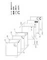
図2(a)に、本実施例にかかる液晶表示装置100の構成の断面を示す。図2(a)に示すように、液晶表示装置100は、光源1、導光板2、液晶表示パネル(液晶表示媒体)13、及び偏光選択反射板(偏光選択反射手段)12よりなっている。光源1及び導光板2によりバックライト(光照射手段)14を構成し、このバックライト14を挟んで、液晶表示パネル13と偏光選択反射板12とが設けられている。また、本明細書では、バックライト14に対して、液晶表示パネル13が設けられている側を表面側(第2の側)とし、その反対の偏光選択反射板12が設けられている側を裏面側(第1の側)とする。また、導光板2から液晶表示パネル13への方向を上方向とし、その反対方向を下方向とする。また、種々の部材において、表面側の面を単に表面とし裏面側の面を裏面とする。 FIG. 2A shows a cross section of the configuration of the liquid
上記導光板2は散乱加工面を有している。光源1から発せられた光は、導光板2の散乱加工面3により散乱され、該導光板2から前面側へ向けて照射される光と、裏面側へ向けて照射される光とに分かれる。なお、バックライト14は、光源1及び導光板2を備えていれば、図示のものに特に限定しない。 The
液晶表示装置100の裏面側に配置されている偏光選択反射板12は、自身に入射する直線偏光の偏光方向が反射軸と平行であるときには、この光を反射し、偏光方向が透過軸と平行であるときにはこの光を透過させる。これにより、バックライト14から無偏光の光が偏光選択反射板12に入射すると、特定の偏光方向の光(一方直線偏光)は反射し、それとは異なる偏光方向の光(他方直線偏光)は透過する。すなわち、偏光選択反射板12は、透過軸及び反射軸の設定により、異なる偏光方向の光を選択的に透過もしくは反射させる機能を有する。本実施の形態では、高分子膜を積層することで作成された既知の偏光選択反射板を用いたが、一方直線偏光を透過し、他方直線偏光を反射する偏光選択反射板であればよい。 The polarization
また図2(b)に、上記液晶表示装置100を携帯電話等に採用した場合の構成の概略断面図を示す。ケース613の表面側には液晶表示パネル13の画面表示領域を空けた表示窓615を、裏面側には表示窓615とほぼ同じ大きさの採光窓616を設けている。 FIG. 2B shows a schematic cross-sectional view of the configuration when the liquid
上記液晶表示パネル13は、第1偏光板4、第1透明基板5、スイッチング素子605、液晶層6、透明電極607、カラーフィルター608、第2透明基板7、及び第2偏光板8を備えている。一対の透明基板である第1透明基板5と第2透明基板7との間に液晶層6を挟んだ構成になっており、裏面側に第1透明基板5、表面側に第2透明基板7が設けられている。第1偏光板4は、第1透明基板5の裏面に設けられており、第2偏光板8は第2透明基板7の表面に設けられている。なお、第1透明基板5にはスイッチング素子605が設けられ、第2透明基板7にはカラーフィルター608及び透明電極607が設けられている。 The liquid
液晶層6は、例えばTN(Twist Nematic)液晶からなる。本実施の形態では、液晶層6は、自身に入射されて通過する直線偏光の光に対して電圧の無印加時に偏光方向を90°回転させる制御を行い、電圧の印加時に偏光方向を回転させない制御を行う。液晶層6は、TN液晶に限定されず、通過する光の偏光状態を制御することができる液晶であればよい。 The
第1偏光板4及び第2偏光板8は、所定の向きに設定された透過軸を有し、透過軸方向の直線偏光の成分となる光のみを透過させる。バックライト14から無偏光の光が第1偏光板4に入射すると、第1偏光板4はその透過軸に平行な直線偏光のみを透過する。また、上記液晶層6を透過した直線偏光が、第2偏光板8に入射すると、第2偏光板8はその透過軸に平行な直線偏光のみを透過する。 The first polarizing plate 4 and the second
第1偏光板4及び第2偏光板8の材料としては、高分子樹脂フィルムにヨウ素、二色性染料等の吸収体を混入し延伸することで配向させたものが好ましいが、これに限定されず、特定の直線偏光を透過させることができるものであればよい。 The material of the first polarizing plate 4 and the second
カラーフィルター608は、第2透明基板7の裏面にRGBの3色分がそれぞれ設けられている。 The
透明電極607は、第2透明基板7上でカラーフィルター608の液晶層6側の面に設けられている。透明電極材料としてはITO(酸化インジウムと酸化錫からなる合金)が好適であるが、これに限定されず、他の透明性を有する導電性金属膜を用いてもよい。又、本実施例では金属からなる透明電極材料を用いた例を記載しているが、金属以外の樹脂、半導体等の透明性を有する導電性材料であればよい。 The
スイッチング素子605は、第1透明基板5の表面に設けられ、各画素を駆動するためにスイッチングするTFTなどのアクティブ素子である。 The switching
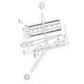
ここで、例えばTFT素子を用いた場合のスイッチング素子605の構成について、図3及び図4を用いて説明する。 Here, for example, a configuration of the
スイッチング素子605は、図3に示すように、ゲート電極(ゲート電極線)701、ゲート絶縁膜702、i型アモルファスシリコン層703、n+型アモルファスシリコン層704、ソース電極(ソース電極線)705、画素電極706により形成されている。 As shown in FIG. 3, the switching
また、図4に示すように、第1透明基板5上において、ゲート電極(ゲート電極線)701とソース電極(ソース電極線)705とが格子状に設けられている。さらに、隣り合うゲート電極(ゲート電極線)701の間には、該ゲート電極(ゲート電極線)701と平行して補助容量配線802が配置されている。 Further, as shown in FIG. 4, on the first
スイッチング素子605は、図3に示すように、第1透明基板5上に、ゲート電極701を有し、その上にゲート絶縁層702を有している。 As shown in FIG. 3, the switching
ゲート電極701上には上記ゲート絶縁層702を介してi型アモルファスシリコン層703が形成されている。さらにその上にn+型アモルファスシリコン層704を介してソース電極705及び画素電極706が形成されている。ソース電極705及び画素電極706の端部はi型アモルファスシリコン層703上に位置する。ソース電極705の他端部はゲート絶縁層702上に位置する。また、画素電極706の他端部はゲート絶縁層702上に位置する。 An i-type
ここで、液晶表示装置100において、偏光を制御する部材の軸構成(ここで、軸構成とは、透過軸、反射軸、及び液晶層の配向方向の構成とする)について図5を用いて説明する。上記部材として、偏光選択反射板12、第1偏光板4、液晶層6及び第2偏光板8が挙げられる。図5の白抜き矢印は偏光板の透過軸を示している。また、参照符号6a及び6bは、それぞれ液晶層6の表面側の液晶分子層と裏面側の液晶分子層を示しており、実線の矢印は液晶分子の配向方向を示している。 Here, in the liquid
液晶表示パネル13は、図5に示すように、第1偏光板4及び第2偏光板8によって液晶層6を挟む構造となっており、液晶層6は厚さ方向に90°捩れたTN配向を有している。 As shown in FIG. 5, the liquid
また、第1偏光板4及び第2偏光板8の透過軸は、互いに直交するように設定されている。さらに、偏光選択反射板12の透過軸は、第1偏光板4と同じ方向になるように設定されている。また、反射軸は、この透過軸と直交するように設定されている。 The transmission axes of the first polarizing plate 4 and the second
このような構造を用いることにより、偏光選択反射板12の裏面から入射した周囲光が、第1偏光板4をほとんどロス無く通過できるため、強い周囲光下でも十分な視認性を得ることができる。 By using such a structure, since the ambient light incident from the back surface of the polarization
例えば、直射日光下(60000ルクス)で、通常の透過型液晶表示装置はバックライトからの光の輝度が、液晶表示パネル表面反射に対して十分でないため、コントラストは10以下に低下するのに対して、本実施の形態にかかる液晶表示装置100は裏面からの光を利用することでコントラスト20以上が確保でき、非常に美しい画像が表示できることが確認できた。さらに、液晶表示装置100の最も裏面側に偏光選択反射板12を配置しているため、裏面からは表示を確認することができず、十分にプライバシーを保護できる事が確認できた。 For example, under direct sunlight (60000 lux), the contrast of the normal transmissive liquid crystal display device is reduced to 10 or less because the luminance of light from the backlight is not sufficient for reflection on the surface of the liquid crystal display panel. Thus, it was confirmed that the liquid
次に、上記液晶層6がTN層である場合の表示方法について、図1を用いて説明する。図1は、本実施の形態にかかる液晶表示装置100の構成の概略及び画面表示の原理を示す断面図である。ここでは、第1偏光板4、第2偏光板8、及び偏光選択反射板12の軸構成を、下記のように、紙面に対して平行方向(以下、x方向(図5に示すx方向)とする)もしくは垂直方向(以下、y方向(図5に示すy方向)とする)に設定した場合について説明する。 Next, a display method when the
図1では、第1偏光板4の透過軸は、x方向(第1の偏光状態)に設定され、第2偏光板8の透過軸は、y方向(第2の偏光状態)に設定されている。また、偏光選択反射板12の反射軸をy方向に設定し、透過軸をx方向に設定している。 In FIG. 1, the transmission axis of the first polarizing plate 4 is set in the x direction (first polarization state), and the transmission axis of the second
液晶表示装置100は、画面表示のために、バックライト14から発せられる光及び裏面に照射される周囲光を利用することができる。 The liquid
まず、液晶表示装置100の裏面に照射される周囲光(無偏光の光)の動作について図1により説明する。なお、図1、図8、図9、図12、及び図13において、両方向矢印及び八方方向の矢印並びに○付の×印は、それぞれ光の偏光状態を示している。すなわち、両方向矢印はx方向の偏光状態を表わし、八方方向の矢印は無偏光の状態を表わし、○付の×印はy方向の偏光状態を表わしている。図1に示すように、液晶表示装置100の裏面に照射される周囲光のうち、偏光選択反射板12によりy方向の直線偏光は反射され、x方向の直線偏光は透過する。偏光選択反射板12を透過したx方向の直線偏光(第1の直線偏光)は、液晶表示パネル13へ到達する。そして、第1偏光板4を偏光方向を変えずに透過し、液晶層6により偏光方向を90°回転してy方向の直線偏光(第2の直線偏光)になる。さらに、この光は、第2偏光板8を偏光方向を変えずに透過し、観察者に到達する。 First, the operation of ambient light (non-polarized light) irradiated on the back surface of the liquid
このように、液晶表示装置100の裏面に照射される周囲光(無偏光の光)のうち、y方向の直線偏光は偏光選択反射板12で反射する。したがって、観察者が液晶表示装置100の裏面側から観察すると鏡のように見える。このため、観察者は、液晶表示装置100の裏面側から表示画面を確認することができなくなりプライバシーを保護することができる。 Thus, of the ambient light (non-polarized light) irradiated on the back surface of the liquid
また、偏光選択反射板12は、周囲光のうちx方向の直線偏光を透過する。そして、その光が液晶表示装置100の画面表示に使用される。これにより、液晶表示装置100の裏面に照射される周囲光を効率的に画面表示に利用することができる。すなわち、周囲光が強い環境下でも良好な画面表示を可能にする液晶表示装置を実現することができる。 The polarization
次に、バックライト14から発せられた光の動作について説明する。この光は、上述したように、導光板2に形成された散乱加工面3で散乱され、上方向の光と下方向の光に分かれる。上方向の光は液晶表示パネル13に到達し、下方向の光は偏光選択反射板12に到達する。 Next, the operation of light emitted from the
上記の上方向の光(無偏光の光)は、第1偏光板4を通過しx方向の直線偏光になる。さらに液晶層6にて偏光方向を90°回転しy方向の直線偏光となる。この光は、偏光方向を変えずに第2偏光板8を通過して観察者に到達する。 The upward light (unpolarized light) passes through the first polarizing plate 4 and becomes linearly polarized light in the x direction. Further, the polarization direction is rotated by 90 ° in the
一方、上記の下方向の光(無偏光の光)のうち、偏光選択反射板12でy方向の直線偏光成分は反射され、液晶表示パネル13に到達する。また、x方向の直線偏光成分は偏光選択反射板12を透過し裏面側へ出射される。上記の液晶表示パネル13に到達した、y方向の直線偏光成分の反射光は、その偏光方向が第1偏光板4の透過軸方向と異なることから、第1偏光板4で吸収される。したがって、この下方向の光は画面表示に使用されない。 On the other hand, among the downward light (unpolarized light), the linearly polarized light component in the y direction is reflected by the polarization
ここでは、偏光選択反射板12の反射軸及び透過軸を、y方向の直線偏光を反射して、x方向の直線偏光を透過するように設定したが、これに限らず、偏光選択反射板12の透過軸をy方向から0°から90°のうち任意の角度に捻った配置とすることも可能である。これにより、バックライト14から偏光選択反射板12に反射した光と液晶表示装置100の裏面へ入射する周囲光との利用程度を制御することができる。 Here, the reflection axis and the transmission axis of the polarization
また、ここでは特定の直線偏光を反射し、これに垂直な直線偏光を透過する偏光選択反射板12を使用した場合について説明したが、これに限らず、特定の円偏光を反射し、これと逆回転の円偏光を透過する円偏光選択反射板を用いても同様の効果が得られる。このとき、円偏光選択反射板と導光板の間に位相差板を配置し、任意の位相差を選択する事で、上記した偏光選択反射板12の透過軸方向を変化させるのと同等の効果が得られる。 In addition, although the case where the polarization
〔実施の形態2〕
本発明にかかる他の実施形態について、図6〜図9に基づいて説明すれば、以下のとおりである。なお、説明の便宜上、上記実施の形態1にて説明した部材と同じ機能を有する部材については、同じ符号を付記し、その説明を省略する。また、上記実施の形態1で述べた各種の特徴点については、本実施の形態についても組み合わせて適用し得るものとする。[Embodiment 2]
Another embodiment according to the present invention will be described below with reference to FIGS. For convenience of explanation, members having the same functions as those described in the first embodiment are given the same reference numerals, and descriptions thereof are omitted. In addition, the various feature points described in the first embodiment can be applied in combination with the present embodiment.
図6は、本実施の形態にかかる液晶表示装置101の概略構成を示す断面図である。 FIG. 6 is a cross-sectional view showing a schematic configuration of the liquid
上記実施の形態1にかかる液晶表示装置100では、バックライト14において液晶表示パネル13と反対側に偏光選択反射板12を設けた構成であった。これに対して、本実施の形態にかかる液晶表示装置101は、バックライト14の裏面側において、偏光選択反射板212に加えて偏光制御液晶パネル15を設けることにより、バックライト14から発せられた光をより有効に利用することができるものである。 The liquid
すなわち、液晶表示装置101は、光源1及び導光板2からなるバックライト14、液晶表示パネル(液晶表示媒体)13、偏光制御液晶パネル(偏光制御液晶媒体)15、及び偏光選択反射板(偏光選択反射手段)212を備えている。バックライト14に対して表面側に液晶表示パネル13が設けられ、裏面側に偏光選択反射板212が設けられている。また、バックライト14と偏光選択反射板212との間に偏光制御液晶パネル15が配置されている。 That is, the liquid
この構成において、偏光制御液晶パネル15は、駆動電圧の印加の有無により、自身を通過する光の偏光方向を制御することができる。これにより、バックライト14から下方向に照射される光を有効に画面表示に利用することができる。 In this configuration, the polarization control
上記偏光制御液晶パネル15は、第1透明基板9、第1透明電極1002、偏光制御用液晶層10、第2透明電極1004、第2透明基板11、及び駆動回路1006を備えている。第1透明基板9と第2透明基板11との間に偏光制御用液晶層10を挟んだ構成になっており、表面側に第1透明基板9、裏面側に第2透明基板11が設けられている。 The polarization control
また、第1透明基板9及び第2透明基板11は、それぞれ第1透明電極1002及び第2透明電極1004を介して偏光制御用液晶層10と接触している。ここで第1透明電極1002及び第2透明電極1004は、少なくとも液晶表示パネル13の画面表示領域を含むように一面に配置されており、偏光制御用液晶層10は、駆動回路1006によって全面同時に駆動される。 The first
偏光制御用液晶層10は、例えばTN液晶からなる。本実施の形態では、偏光制御用液晶層10は、自身に入射されて通過する直線偏光の光に対して電圧の無印加時に偏光方向を90°回転させる制御を行い、電圧の印加時に偏光方向を回転させない制御を行う。液晶層10は、TN液晶に限定されず、通過する光の偏光状態を制御することができる液晶であればよい。 The polarization control
このような液晶としては、例えば、平行配向液晶が挙げられる。この場合、その位相差をλ/2となるように設定することにより、TN液晶の場合と同様に直線偏光を90°捻ることができる。さらに電圧を印加することにより、液晶分子を基板に対して垂直に配向させると、位相差が消失し、通過する光の偏光軸は変化しない。このように、平行配向液晶を用いても、TN液晶と全く同様の動作を行うことが可能になる。 An example of such a liquid crystal is a parallel alignment liquid crystal. In this case, by setting the phase difference to be λ / 2, the linearly polarized light can be twisted by 90 ° as in the case of the TN liquid crystal. Further, when liquid crystal molecules are aligned perpendicularly to the substrate by applying a voltage, the phase difference disappears and the polarization axis of the light passing therethrough does not change. As described above, even when the parallel alignment liquid crystal is used, the same operation as that of the TN liquid crystal can be performed.
次に、液晶表示装置101において偏光方向を制御する部材の軸構成を図7に示す。図7において、偏光方向を制御するものとしては、液晶表示パネル13と偏光制御用液晶層10と偏光選択反射板212が挙げられる。液晶表示パネル13の軸構成は上記実施の形態1と同一である。したがって、ここでは、偏光制御用液晶層10及び偏光選択反射板212の軸構成に関して説明する。 Next, FIG. 7 shows a shaft configuration of a member that controls the polarization direction in the liquid
ここで、10a及び10bはそれぞれ偏光制御用液晶層10の表面側の液晶分子層と裏面側の液晶分子層を示している。図7に示すように、偏光制御用液晶層10は厚さ方向に90°捩れたTN配向を有している。 Here, 10a and 10b respectively indicate a liquid crystal molecular layer on the front surface side and a liquid crystal molecular layer on the back surface side of the
さらに、偏光選択反射板212の透過軸は、第1偏光板4の透過軸に直交するように設定されている。そして、反射軸はこの透過軸と直交するように設定されている。ここで、液晶表示装置101の偏光選択反射板212としては、住友3M社製のD−BEFフィルムを用いた。しかし、偏光選択反射板212として、これに限定されず、Al薄膜を1/4波長以下でスリット状に形成するワイヤーグリッド偏光板なども使用可能である。また、偏光選択反射板212の軸構成は、これに限定されず、透過軸を第1偏光板4の透過軸に対して平行に設定することも可能である。 Further, the transmission axis of the polarization
上述のように軸構成を設定すると、偏光制御用液晶層10に電圧を印加しない状態では、偏光選択反射板212を透過した周囲光の直線偏光は、偏光制御用液晶層10によって90°捻られ、第1偏光板4の透過軸と同じになる。そして、ほとんどロス無く第1偏光板4を通過することができるため、強い周囲光下でも十分な視認性を得ることができる。 When the axis configuration is set as described above, in the state where no voltage is applied to the polarization control
例えば、直射日光下(60000ルクス)で、通常の透過型液晶表示装置は、バックライトからの光の輝度がパネル表面反射に対して十分でないため、コントラストが10以下に低下してしまう。これに対して、液晶表示装置101は、裏面からの周囲光を利用することにより、コントラストを20以上に確保することができる。したがって、周囲光が十分強い環境下でも非常に美しい画像が表示することができる液晶表示装置を提供することができる。 For example, under direct sunlight (60000 lux), a normal transmissive liquid crystal display device has a contrast of 10 or less because the luminance of light from the backlight is not sufficient for panel surface reflection. On the other hand, the liquid
ただし、この場合、後述するバックライト14から下方向に出射した光は有効に使うことができないため、室内など周囲光が比較的弱い環境では、通常の透過型液晶表示装置より暗くなる。 However, in this case, light emitted downward from the
そこで、偏光制御用液晶層10に十分に大きな電圧を印加すると、偏光制御用液晶層10の液晶分子は基板に対し垂直に配向する。これにより偏光制御用液晶層10を通過する光の偏光状態は変化しなくなる。 Therefore, when a sufficiently large voltage is applied to the polarization control
このような状態では、偏光選択反射板212を反射した導光板2からの光は、偏光状態を変化することなく偏光制御用液晶層10を透過し第1偏光板4に到達するため、導光板2からの光を最も効率よく利用することが可能となる。また、このときの画面表示が通常の透過型液晶表示装置と全く同等の明るさである事を確認することができた。 In such a state, the light from the
ここでは、偏光制御液晶パネル15に対して十分に大きな電圧を印加した場合と、電圧を印加しない場合とを記載したが、その中間の電圧を印加することで、周囲光を利用する状態と導光板裏面出射光を利用する状態を連続的に切り換えることも可能である。 Here, a case where a sufficiently large voltage is applied to the polarization control
また、液晶表示装置101の最も裏面側に偏光選択反射板212を配置しているため、裏面からは表示を確認することができず、十分にプライバシーを保護することができる。 Further, since the polarization
次に、上記液晶層6及び偏光制御用液晶層10がTN層である場合の表示方法について、図8及び図9を用いて詳細に説明する。ここで偏光選択反射板212は、x方向の直線偏光は反射し、y方向の偏光は透過するように軸構成を設定している。 Next, a display method when the
はじめに、図8を用いて、室内など比較的周囲光が強くない環境で、光源1から発せられる光を最も有効に利用する場合を説明する。 First, the case where the light emitted from the
上述したように、光源1より出射した光は、導光板2に形成された散乱加工面3で散乱し、上方向に出射した光(無偏光)と下方向に出射した光(無偏光)とに分かれる。 As described above, the light emitted from the
上方向に出射した光は、液晶表示パネル13に到達し、第1偏光板4を通過する時、x方向の偏光だけが選択的に透過し、液晶層6にて90°捻られ、y方向の偏光となり、第2偏光板8を通過して観察者に到達する。 When the light emitted upward reaches the liquid
一方、下方向に出射した光は、偏光制御液晶パネル15を通過し、偏光反射板212に到達する。そして、偏光選択反射板212でx方向の直線偏光のみが反射される。偏光制御液晶パネル15に電圧を印加して偏光制御用液晶層10を垂直配向状態にすると、反射されたx方向の直線偏光は、偏光方向を変えずに偏光制御液晶パネル15を透過し液晶表示パネル13に到達する。そして、この光は第1偏光板4をロス無く透過し、液晶層6及び第2偏光板8を経て観察者に到達する。このように、偏光制御液晶パネル15に電圧を印加することにより、下方向に出射した光を有効に画面表示に利用することができる。 On the other hand, the light emitted downward passes through the polarization control
次に、図9を用いて、周囲光が強い環境で、裏面からの周囲光を有効に利用する方法を説明する。この環境下では、偏光制御液晶パネル15に電圧を印加しないことにより、裏面からの周囲光を有効に画面表示に利用することができる。 Next, a method for effectively using ambient light from the back surface in an environment with strong ambient light will be described with reference to FIG. Under this environment, by applying no voltage to the polarization control
光源1より出射した光は導光板2に入射し、導光板2に形成された散乱加工面3で散乱し、上下方向に出射される。上方向に出射した光は、画像表示用の第一の液晶表示パネル13に到達し、第1偏光板4を通過する時、x方向の直線偏光だけが選択的に透過し、液晶層6にて90°捻られy方向の直線偏光となり、第2偏光板8を通過して観察者に到達する。 The light emitted from the
下方向に出射した光は、偏光制御液晶パネル15を通過し、偏光選択反射板212に到達する。偏光制御液晶パネル15に電圧を印加しない状態にすると、偏光制御用液晶層10はTN液晶になる。これにより、偏光選択反射板212で反射したx方向の直線偏光は、偏光制御用液晶層10を通過すると90°捻られy方向の直線偏光になり、第1偏光板4にて吸収される。したがって、この下方向に出射した光は、画面表示に利用されない。 The light emitted downward passes through the polarization control
一方、偏光選択反射板212の裏面側から入射した周囲光は、偏光選択反射板212を通過する時、y方向の直線偏光になる。さらに、偏光制御液晶パネル15を通過すると90°捻られ、x方向の直線偏光となる。そして、この光は、液晶表示パネル13の第1偏光板4をロス無く透過し、液晶層6及び第2偏光板8を経て観察者に到達する。このように、偏光制御液晶パネル15に電圧を印加しない状態にすることにより、周囲光が強い環境下でも画面表示が良好な液晶表示装置101を実現することができる。 On the other hand, ambient light incident from the back side of the polarization
以上のことから、電圧の印加、無印加により光の偏光方向を制御する偏光制御液晶パネル15を設けることにより、周囲光が比較的強くない環境下でも、光源1からの光を画面表示に有効に利用できる液晶表示装置を実現することができる。 As described above, by providing the polarization control
また、偏光選択反射板212の軸構成を、x方向の直線偏光は反射しy方向の偏光は透過するように設定していたが、これに限定されず、y方向の直線偏光は反射し、x方向の偏光は透過するように設定してもよい。 In addition, although the axial configuration of the polarization
この場合、周囲光が強い環境下で偏光制御用液晶層10の駆動電圧を印加し、周囲光が比較的強くない環境下でこの駆動電圧を印加しないことにより、上記の光源1からの光を有効に利用できる液晶表示装置を実現することができる。 In this case, the drive voltage of the polarization control
〔実施の形態3〕
本発明にかかるさらに他の実施形態について、図10〜図13に基づいて説明すれば、以下のとおりである。なお、説明の便宜上、前記実施の形態1及び実施の形態2にて説明した部材と同じ機能を有する部材については、同じ符号を付記し、その説明を省略する。また、前記実施の形態1及び実施の形態2で述べた各種の特徴点については、本実施の形態についても組み合わせて適用し得るものとする。[Embodiment 3]
Still another embodiment according to the present invention will be described below with reference to FIGS. For convenience of explanation, members having the same functions as those described in the first and second embodiments are denoted by the same reference numerals, and the description thereof is omitted. Further, the various feature points described in the first embodiment and the second embodiment can be applied in combination with the present embodiment.
実施の形態1ないし2では、偏光選択反射板として、直線偏光を透過もしくは反射させるものを用いたが、他の偏光選択反射板を用いても同じことが言える。本実施の形態では、偏光選択反射板として、円偏光を透過もしくは反射させるものを用いた場合を説明する。 In
図10に、液晶表示装置102の断面構成を示す。液晶表示装置102は、液晶表示パネル13、光源1、導光板2、偏光制御液晶パネル315、位相差板16、及び偏光選択反射板312を備えている。光源1及び導光板2でバックライト14を形成している。バックライト14に対して最も裏面側に偏光選択反射板312が設けられている。偏光選択反射板312からバックライト14に向かって順に位相差板16及び偏光制御液晶パネル315が設けられている。 FIG. 10 shows a cross-sectional configuration of the liquid
上記偏光制御液晶パネル315は、第1透明基板39、第1透明電極3002、偏光制御用液晶層310、第2透明電極3004、第2透明基板311、及び駆動回路3006を備えている。第1透明基板39と第2透明基板311との間に偏光制御用液晶層310を挟んだ構成になっており、表面側に第1透明基板39、裏面側に第2透明基板311が設けられている。 The polarization control
また、第1透明基板39及び第2透明基板311は、それぞれ第1透明電極3002及び第2透明電極3004を介して偏光制御用液晶層310と接触している。ここで第1透明電極3002及び第2透明電極3004は、少なくとも液晶表示パネル13の画面表示領域を含むように一面に配置されており、偏光制御用液晶層310は、駆動回路3006によって全面同時に駆動される。 The first
上記偏光制御用液晶層310は、リタデーションが約λ/2(△n・d=220nm:ここで△nは液晶の複屈折、dは液晶のセル厚)の平行配向のネマティック液晶層である。 The polarization control
上記位相差板16は、裏面側から入射する円偏光の光を直線偏光にする。 The
また、偏光選択反射板312は、入射する右円偏光の光を反射させ左円偏光の光を透過させるものである。液晶表示装置103では、偏光選択反射板312として日東電工製PCFフィルムを用いたが、これに限らず、コレステリック液晶を高分子に分散させた、コレステリック液晶ポリマーなども使用可能である。また、左円偏光の光を反射させ右円偏光の光を透過させた偏光選択反射板でもよい。 The polarization
次に、液晶表示装置102において偏光方向を制御する部材の軸構成を図11に示す。偏光方向を制御するものとして、液晶表示パネル13と偏光制御用液晶層310と位相差板16と偏光選択反射板312が挙げられる。液晶表示パネル13の軸構成は上記実施の形態1及び実施の形態2と同一である。ここでは、偏光制御用液晶層310及び位相差板16並びに偏光選択反射板312の軸構成に関して説明する。 Next, FIG. 11 shows an axis configuration of a member that controls the polarization direction in the liquid
ここで、310a及び310bはそれぞれ偏光制御用液晶層310の表面側の液晶分子層と裏面側の液晶分子層を示している。図11に示すように、偏光制御用液晶層310は厚さ方向に捩れのない平行配向を有しており、その配向方向は第1偏光板4の透過軸に対して45°右捩れの方向となるよう設定されている。 Here,
さらに、位相差板16の遅相軸は、偏光制御用液晶層310の配向方向と90°捩れた方向とし、そのリタデーションはλ/4となるように設定した。 Further, the slow axis of the
偏光選択反射板312の透過回転方向は左回りであるものを配置した。 The polarization
上述のような構造を用いると、偏光制御用液晶層310に電圧を印加しない状態では、偏光選択反射板312の裏面側から入射した左回りの直線偏光が、位相差板16によって、第1偏光板4の透過軸に垂直な方向の直線偏光となり、更に偏光制御用液晶層310によって、第1偏光板4の透過軸に平行な方向の直線偏光となる。従って、第1偏光板4をほとんどロス無く通過できるため、強い周囲光下でも十分な視認性を得ることができた。 When the structure as described above is used, in the state where no voltage is applied to the polarization control
例えば、直射日光下(60000ルクス)で、通常の透過型液晶表示装置はバックライトの輝度が、パネル表面反射に対して十分でないため、コントラストは10以下に低下するのに対して、液晶表示装置103は裏面からの光を利用することでコントラスト50以上が確保でき、非常に美しい画像が表示できることが確認できた。ただし、この場合導光板2から下方向に出射した光は有効に使うことができないため、室内など周囲光が比較的弱い環境では、通常の透過型液晶表示装置より暗くなる。 For example, under direct sunlight (60000 lux), a normal transmissive liquid crystal display device has a backlight whose luminance is not sufficient for reflection on the panel surface. It was confirmed that No. 103 can secure a contrast of 50 or more by using light from the back surface and can display a very beautiful image. However, in this case, since the light emitted downward from the
そこで偏光制御用液晶層310に十分に大きな電圧を印加すると、偏光制御用液晶層310の液晶分子が立ち上がり、自身を通過する光の偏光状態は変化しなくなる。このような状態では導光板2より下向きに出射した光のうち、右回りの円偏光が偏光選択反射板312で反射し、位相差板16を通過することで、第1偏光板4の透過軸と平行な直線偏光となる。ここで、偏光制御用液晶層310には十分な電圧を印加され、垂直配向をしているため、偏光状態を変化させないので、導光板からの光を最も効率よく利用することが可能となる。このような状態では通常の透過型液晶表示装置と全く同等の明るさである事が確認できた。 Therefore, when a sufficiently large voltage is applied to the polarization control
ここでは、偏光制御用液晶層310に対して十分に大きな電圧を印加した場合と、電圧を印加しない場合を記載したが、その中間の電圧を印加することで、周囲光を利用する状態と導光板2から下向きに出射された光を利用する状態とを連続的に切り換えることも可能である。 Here, a case where a sufficiently large voltage is applied to the polarization control
また、偏光制御用液晶層310の最も裏面側に偏光選択反射板312を配置しているため、裏面側からは表示を確認することができず、十分にプライバシーを保護することができる。 In addition, since the polarization
次に、液晶表示装置103の表示方法について、図12及び図13を用いて詳細に説明する。ここで、偏光選択反射板312は、右円偏光の光を反射させ左円偏光の光を透過させるように設定されている。 Next, a display method of the liquid crystal display device 103 will be described in detail with reference to FIGS. Here, the polarization
はじめに、図12を用いて、室内など周囲光の強くない環境で、バックライト14からの光を最も有効に利用する場合を説明する。 First, the case where the light from the
上述のように、バックライト14から上方向に出射した光は、偏光板4を通過する時、x方向の直線偏光だけが選択的に透過し、液晶層6にて90°捻られy方向の直線偏光となり、偏光板8を通過して観察者に到達する。 As described above, when the light emitted upward from the
一方、下方向に出射した光は、偏光制御用液晶層310、位相差板16を経て、偏光反射板12に到達する。下方向に出射した光は偏光選択反射板312に到達したときは、まだランダム偏光のままである。しかしながら、偏光選択反射板312によって、右円偏光は反射し左円偏光は透過する。反射された右円偏光は位相差板16を通過するとき偏光状態が変化し、位相差板16をλ/4条件に設定すると、位相差板16の遅相軸に対して右45°方向の直線偏光となる。ここでは簡単のためx方向の直線偏光となることとする。 On the other hand, the light emitted downward passes through the polarization control
さらに、偏光制御用液晶層310に電圧を印加して垂直配向状態にすると、このx方向の直線偏光は、偏光状態を変えずに液晶表示パネル13に到達する。そして、この光は、第1偏光板4をロス無く透過し、液晶層6及び第2偏光板8を経て観察者に到達する。 Further, when a voltage is applied to the polarization control
次に、周囲光が強い環境で、液晶表示装置103の裏面側からの入射光を有効に利用する方法を、図13を用いて説明する。 Next, a method of effectively using incident light from the back side of the liquid crystal display device 103 in an environment with strong ambient light will be described with reference to FIG.
光源1から発せられた光のうち、導光板2の散乱加工面3により上方向に出射した光は、図12と同様に液晶表示パネル13を経て観察者に到達する。 Of the light emitted from the
一方、下方向に出射した光は、偏光制御用液晶層310及び位相差板16を通過し、偏光選択反射板312に到達する。偏光選択反射板312で反射した右円偏光の光は、位相差板16によりx方向の直線偏光になる。 On the other hand, the light emitted downward passes through the polarization control
さらに、偏光制御用液晶層310に電圧を印加せずに平行配向状態にする。ここで偏光制御用液晶層310は平行配向状態で位相差板16の遅相軸と垂直な方向に遅相軸を有しており、その位相差はλ/2であるように設定されている。このような構成により、x方向の直線偏光は偏光制御用液晶層310を通過することで90°捩れ、y方向の直線偏光となる。従って、上記のx方向の直線偏光は、第1偏光板4に到達すると吸収されるため、有効に利用することはできない。 Further, the
しかしながら、裏面から入射した周囲光は、偏光選択反射板312を透過するとき、左円偏光となり、更に位相差板16、偏光制御用液晶層310を通過するとx方向の直線偏光となり、更に液晶表示パネル13に到達し、ロス無く利用することが可能となる。 However, the ambient light incident from the back surface becomes left circularly polarized light when passing through the polarization
このように液晶表示パネル13には第1偏光板4が配置されており、この場合はx方向の直線偏光だけを利用するため、裏面側に配置した偏光反射板12が、左円偏光だけを透過してもロスは発生せず、全く有効に光を利用することが可能となる。 In this way, the first polarizing plate 4 is arranged on the liquid
この時、図12,5おいて、偏光制御用液晶層310の平行配向液晶に代わって、TN液晶を配置しても平行配向液晶と同様に偏光軸を90°捻ることが可能となる。更に偏光制御用液晶層310に電圧を印加する事によって、液晶分子を垂直配向させると、通過する光の偏光方向は変化しない。この様にTN液晶を用いても、平行配向液晶と全く同等の動作を行うことが可能となる。 At this time, in FIGS. 12 and 5, even if a TN liquid crystal is arranged instead of the parallel alignment liquid crystal of the polarization controlling
〔実施の形態4〕
本発明にかかるさらに他の実施形態について、図14に基づいて説明すれば、以下のとおりである。なお、説明の便宜上、前記実施の形態にて説明した部材と同じ機能を有する部材については、同じ符号を付記し、その説明を省略する。また、前記実施の形態で述べた各種の特徴点については、本実施の形態についても組み合わせて適用し得るものとする。[Embodiment 4]
Still another embodiment according to the present invention will be described below with reference to FIG. For convenience of explanation, members having the same functions as those described in the above embodiment are given the same reference numerals and explanation thereof is omitted. Further, the various feature points described in the above embodiment can be applied in combination with this embodiment.
図14は、本実施の形態における液晶表示装置104の構成を示す断面図である。同図に示すように、液晶表示装置104は、前面側から背面側に向かって、液晶表示パネル(液晶表示媒体)13、バックライト14、図示しない前記の偏光選択反射板(偏光選択反射手段)12、およびプリズムアレイ(光屈折手段)17を備えている。プリズムアレイ17は、液晶表示装置104の最背面側の位置に設けられている。 FIG. 14 is a cross-sectional view showing a configuration of the liquid
液晶表示装置104は、図2(b)に示したケース(筐体)613にて外面が覆われている。このケース613における背面側の採光窓616は、液晶表示パネル13の全背面からの採光が可能な大きさに形成されている。前記プリズムアレイ17は例えばケース613の採光窓616に嵌め込まれていてもよい。 The outer surface of the liquid
液晶表示装置104は、プリズムアレイ17が設けられている構成およびこれによる作用以外は、実施の形態1において示した液晶表示装置100と同一の構成および作用を有するである。 The liquid
ここで、液晶表示装置104を屋外のような周囲が明るい環境にて使用する場合、液晶表示装置104の背面の採光窓616から採光すると液晶表示装置104の輝度が向上し、視認性が向上する。しかしながら、液晶表示パネル13は、表示面が上を向くように傾けた状態にて使用されるのが通常である。したがって、この場合には、採光方位が背面下方となってしまい(液晶表示装置104の背面に対して垂直な入射方向が斜め上向きとなってしまい)、大きな採光効果が得られない。そこで、液晶表示装置104では、より光量の多い液晶表示装置104の背面上方から採光するために、上記のようにプリズムアレイ17を設けている。即ち、プリズムアレイ17は、液晶表示装置104の背面に対して斜め上方から入射した光を液晶表示装置104の前面方向に屈折させる機能を有する。 Here, in the case where the liquid
上記のプリズムアレイ17は、例えば光屈折フィルムからなり、複数のプリズム17aが並設された構造を有する透明基材である。各プリズム17aは、液晶表示パネル13の表示面に対して傾いた傾斜面17a1を有し、この面の境界前後で屈折率が異なる。 Said
本実施の形態において、プリズムアレイ17は、屈折率が1.57の透明基材にて形成され、各プリズム17aは、空気界面に対して22度傾斜した傾斜面17a1を有する。このプリズムアレイ17は、プリズム17aの形成面である凹凸面が液晶表示パネル13側を向き、かつ傾斜面17a1が液晶表示装置104の上方を向く状態にて配置されている。 In the present embodiment, the
上記の構成において、液晶表示装置104の背面の斜め上方から液晶表示装置104の背面に入射した光は、直進するのではなく、観察者が液晶表示装置104を観視する方向(液晶表示装置104の前面方向)にプリズムアレイ17によって屈折される。 In the above configuration, light incident on the back surface of the liquid
実際に様々な環境にて照度を測定した結果を表1に示す。測定環境は屋外(直射日光下)、屋外(日陰)、室内、室内(廊下)、室内(窓際)であり、それぞれの環境下において測定器を上方、横方向、下方に向けてそれぞれ測定した。その結果、各所の照度はいずれの場所であっても、測定器を上方に向けて測定した場合の方が下方に向けて測定した場合よりも3〜6倍の照度があった。この結果から、下方からよりも上方から採光した場合の方が大きな採光効果が得られることが容易に理解できる。 Table 1 shows the results of actually measuring the illuminance in various environments. The measurement environment was outdoor (in direct sunlight), outdoor (in the shade), indoors, indoors (corridor), and indoors (by the window). Under each environment, the measuring instrument was measured upward, laterally, and downward. As a result, the illuminance at each location was 3-6 times higher when measured with the measuring device facing upward than when measured with the measuring device facing downward. From this result, it can be easily understood that a larger lighting effect can be obtained when the lighting is performed from above than from below.

また、プリズムアレイ17を配置した構成(液晶表示装置104)とそうでない構成(液晶表示装置104からプリズムアレイ17を除いた構成)とにおいて、表示装置の正面輝度を測定したところ、特に屋外や窓際において採光効果の差が顕著に現れ、プリズムアレイ17を配置した場合の方が輝度が高く視認性の高い表示が得られた。 Further, when the front luminance of the display device was measured in a configuration in which the
本実施の形態においては、光屈折手段として傾斜角22度、屈折率1.57のプリズムアレイを用いた。しかしながら、本質的には表示装置背面の光量が大きい方位からの光を観察者の方位へ屈折する作用を有する部材であれば問題無く本発明に適用でき、基材の材質や形状は適宜選択される。例えば3M社製のBEFと呼ばれる、図14に示したものとは異なる形状のプリズムアレイや透過ホログラムディフューザーなども使用できる。 In the present embodiment, a prism array having an inclination angle of 22 degrees and a refractive index of 1.57 is used as the light refracting means. However, it can be applied to the present invention without any problem as long as it is essentially a member having an action of refracting light from the direction with a large amount of light on the back of the display device to the direction of the observer, and the material and shape of the substrate are appropriately selected. The For example, a prism array or a transmission hologram diffuser having a shape different from that shown in FIG.
本発明にかかる液晶表示装置は、一対をなす第1および第2の偏光板の間に液晶層が設けられている液晶表示媒体と、上記液晶表示媒体に対向して第1の偏光板側の位置に設けられ、上記液晶表示媒体側の面とは反対側の面から入射する光のうち、第1の偏光状態を有する成分の光を透過する一方、第1の偏光状態とは異なる第2の偏光状態を有する成分の光を反射する偏光選択反射手段とを備えるとしてもよい。 The liquid crystal display device according to the present invention includes a liquid crystal display medium in which a liquid crystal layer is provided between a pair of first and second polarizing plates, and a position on the first polarizing plate side facing the liquid crystal display medium. Of the light incident from the surface opposite to the surface on the liquid crystal display medium side, the second polarized light that transmits the component light having the first polarization state but is different from the first polarization state. Polarization selective reflection means for reflecting light of a component having a state may be provided.
上記の構成によれば、例えば、液晶表示媒体における第1の偏光板は第1の偏光状態を有する成分の光を透過させ、第2の偏光板は第2の偏光状態を有する成分の光を透過させる。 According to the above configuration, for example, the first polarizing plate in the liquid crystal display medium transmits the light of the component having the first polarization state, and the second polarizing plate transmits the light of the component having the second polarization state. Make it transparent.
偏光選択反射手段に対して液晶表示媒体側の面とは反対側の面から入射する光(周囲光)のうち、第1の偏光状態を有する成分の光は偏光選択反射手段を透過する一方、第2の偏光状態を有する成分の光は偏光選択反射手段にて反射される。 Among the light (ambient light) incident from the surface opposite to the surface on the liquid crystal display medium side with respect to the polarization selective reflection means, the light of the component having the first polarization state is transmitted through the polarization selective reflection means. The component light having the second polarization state is reflected by the polarization selective reflection means.
偏光選択反射手段を透過した第1の偏光状態を有する成分の光は、液晶表示媒体の第1の偏光板を透過して液晶層に入射し、この液晶層を経て第2の偏光状態を有する成分の光となり、第2の偏光板を透過して観察者に到達する。これにより、液晶表示媒体側の面とは反対側の面から入射する光(周囲光)を有効に利用することができ、周囲光が強い環境下でも良好な画面表示が可能となる。 The component light having the first polarization state transmitted through the polarization selective reflection means is transmitted through the first polarizing plate of the liquid crystal display medium and incident on the liquid crystal layer, and has the second polarization state through the liquid crystal layer. It becomes the component light, passes through the second polarizing plate, and reaches the observer. Thereby, light (ambient light) incident from a surface opposite to the surface on the liquid crystal display medium side can be effectively used, and a good screen display can be performed even in an environment with strong ambient light.
また、上記のように、周囲光のうち、第2の偏光状態を有する成分の光は偏光選択反射手段にて反射されるので、液晶表示装置の裏面側からは表示画面を見ることができなくなる。したがって、使用者のプライバシーを保護することができる。 Further, as described above, the light of the component having the second polarization state in the ambient light is reflected by the polarization selective reflection means, so that the display screen cannot be seen from the back side of the liquid crystal display device. . Therefore, the privacy of the user can be protected.
本発明の液晶表示装置は、一対をなす第1および第2の偏光板の間に液晶層が設けられている液晶表示媒体と、上記液晶表示媒体に対向して第1の偏光板側の位置に設けられ、上記液晶表示媒体側の面とは反対側の面から入射する光のうち、第1の偏光状態を有する成分の光を透過する一方、第1の偏光状態とは異なる第2の偏光状態を有する成分の光を反射する偏光選択反射手段と、上記偏光選択反射手段と上記液晶表示媒体との間に設けられ、光源からの光を液晶表示媒体に照射する光照射手段と、上記偏光選択反射手段と上記光照射手段との間に設けられ、偏光選択反射手段から液晶表示媒体へ向かう光の偏光状態を制御する偏光制御手段とを備えている構成としてもよい。 A liquid crystal display device according to the present invention includes a liquid crystal display medium in which a liquid crystal layer is provided between a pair of first and second polarizing plates, and a liquid crystal display medium provided at a position on the first polarizing plate side so as to face the liquid crystal display medium. Among the light incident from the surface opposite to the surface on the liquid crystal display medium side, the light having the first polarization state is transmitted, while the second polarization state is different from the first polarization state. A polarization selective reflection unit that reflects light having a component having light, a light irradiation unit that is provided between the polarization selective reflection unit and the liquid crystal display medium, and irradiates the liquid crystal display medium with light from a light source, and the polarization selection unit. It is good also as a structure provided with the polarization control means which controls the polarization state of the light which is provided between a reflection means and the said light irradiation means, and goes to a liquid crystal display medium from a polarization selective reflection means.
上記の構成によれば、例えば、液晶表示媒体における第1の偏光板は第1の偏光状態を有する成分の光を透過させ、第2の偏光板は第2の偏光状態を有する成分の光を透過させる。 According to the above configuration, for example, the first polarizing plate in the liquid crystal display medium transmits the light of the component having the first polarization state, and the second polarizing plate transmits the light of the component having the second polarization state. Make it transparent.
したがって、光照射手段から液晶表示媒体側へ出射する光源からの光うち、第1の偏光状態の成分を有する光は第1の偏光板を透過し、液晶層に入射する。このとき、第1の偏光板を通過した第1の偏光状態を有する成分の光が第2の偏光状態を有する光の成分となるように、液晶層を動作させれば、その光は観察者に到達する。 Therefore, among the light from the light source emitted from the light irradiation means to the liquid crystal display medium side, the light having the first polarization state component is transmitted through the first polarizing plate and is incident on the liquid crystal layer. At this time, if the liquid crystal layer is operated so that the light component having the first polarization state that has passed through the first polarizing plate becomes the light component having the second polarization state, the light is transmitted to the observer. To reach.
一方、光照射手段から偏光選択反射手段側へ出射した光のうち、第2の偏光状態の成分を有する光は、偏光選択反射手段にて反射され、液晶表示媒体へ向かう。この場合、偏光制御手段は、液晶表示媒体へ向かう光の偏光状態を制御する。このとき、偏光制御手段は、例えば液晶層における液晶分子の配向状態により、偏光選択反射手段にて反射された第2の偏光状態を有する成分の光を第1の偏光状態を有する成分の光に変化させる。これにより、偏光制御手段を経た光は、液晶表示媒体の第1の偏光板を透過し、第2の偏光板を経て観察者に到達する。したがって、光照射手段から出射した光を有効に利用することができる。これにより、周囲光が弱い環境下においても明るい画面表示を得ることができる。 On the other hand, of the light emitted from the light irradiation means to the polarization selective reflection means side, the light having the second polarization state component is reflected by the polarization selective reflection means and travels toward the liquid crystal display medium. In this case, the polarization control unit controls the polarization state of the light traveling toward the liquid crystal display medium. At this time, the polarization control means converts the light of the component having the second polarization state reflected by the polarization selective reflection means into the light of the component having the first polarization state, for example, depending on the alignment state of the liquid crystal molecules in the liquid crystal layer. Change. Thereby, the light that has passed through the polarization control means passes through the first polarizing plate of the liquid crystal display medium, and reaches the observer through the second polarizing plate. Therefore, the light emitted from the light irradiation means can be used effectively. Thereby, a bright screen display can be obtained even in an environment where ambient light is weak.
さらに、偏光選択反射手段の液晶表示媒体側の面とは反対側の面から入射した光(周囲光)のうち、第1の偏光状態を有する成分の光は偏光選択反射手段を透過し、第2の偏光状態を有する成分の光は偏光選択反射手段にて反射される。 Further, of the light (ambient light) incident from the surface opposite to the surface of the polarization selective reflection means on the liquid crystal display medium side, the component light having the first polarization state is transmitted through the polarization selective reflection means. The component light having two polarization states is reflected by the polarization selective reflection means.
このとき、偏光制御手段は例えば液晶層における液晶分子の配向状態により第1の偏光状態を有する成分の光の偏光状態を変えないようにすれば、偏光選択反射手段を透過した光は、偏光制御手段を第1の偏光状態で透過し、さらに液晶表示媒体の第1の偏光板を透過し、第2の偏光板を経て観察者に到達する。 At this time, for example, if the polarization control means does not change the polarization state of the component light having the first polarization state according to the alignment state of the liquid crystal molecules in the liquid crystal layer, the light transmitted through the polarization selective reflection means is polarized. The means is transmitted in the first polarization state, further transmitted through the first polarizing plate of the liquid crystal display medium, and reaches the observer through the second polarizing plate.
すなわち、偏光選択反射手段の液晶表示媒体側の面とは反対側の面から入射する光が強い環境下でも、上記偏光制御液晶媒体による偏光制御により良好な画面表示を行う液晶表示装置を実現することができる。 That is, a liquid crystal display device that realizes a good screen display by polarization control using the polarization control liquid crystal medium is realized even in an environment where light incident from a surface opposite to the liquid crystal display medium side of the polarization selective reflection means is strong. be able to.
また、上記のように、周囲光のうち、第2の偏光状態を有する成分の光は偏光選択反射手段にて反射されるので、液晶表示装置の裏面側からは表示画面を見ることができなくなる。したがって、使用者のプライバシーを保護することができる。 Further, as described above, the light of the component having the second polarization state in the ambient light is reflected by the polarization selective reflection means, so that the display screen cannot be seen from the back side of the liquid crystal display device. . Therefore, the privacy of the user can be protected.
この結果、周囲光が強い環境下でも良好な画面表示を可能にしながら、周囲光が弱い環境下においても明るい画面表示を得ることができるとともに、周囲光が弱い環境下においても明るい画面表示を得ることができる。 As a result, a bright screen display can be obtained even in an environment where the ambient light is weak, and a bright screen display can be obtained even in an environment where the ambient light is weak. be able to.
上記の液晶表示装置において、上記偏光制御手段は、液晶層における液晶分子の配向状態により光の偏光状態を制御する偏光制御液晶媒体である構成としてもよい。 In the liquid crystal display device, the polarization control unit may be a polarization control liquid crystal medium that controls a polarization state of light according to an alignment state of liquid crystal molecules in a liquid crystal layer.
上記の構成によれば、上記偏光制御手段として偏光制御液晶媒体を用いることにより、上記の光照射手段から偏光選択反射手段側へ出射した光を有効に画面表示に利用することができる。 According to said structure, the light radiate | emitted from the said light irradiation means to the polarized-light selective reflection means side can be effectively utilized for a screen display by using a polarization control liquid crystal medium as said polarization control means.
上記の液晶表示装置において、上記偏光制御液晶媒体の液晶層はツイストネマティック液晶層である構成としてもよい。 In the above liquid crystal display device, the liquid crystal layer of the polarization control liquid crystal medium may be a twisted nematic liquid crystal layer.
上記の構成によれば、ツイストネマティック液晶層である偏光制御液晶媒体は、この液晶層における液晶分子の配向状態により、直線偏光の向きを変えることができる。これにより、周囲光を有効に利用することができると共に裏面側から表示画面を見ることができない液晶表示装置を実現することができる。 According to the above configuration, the polarization control liquid crystal medium that is a twisted nematic liquid crystal layer can change the direction of linearly polarized light depending on the alignment state of the liquid crystal molecules in the liquid crystal layer. Accordingly, it is possible to realize a liquid crystal display device that can effectively use ambient light and cannot view the display screen from the back side.
上記の液晶表示装置において、上記偏光制御液晶媒体の液晶層は平行配向のネマティック液晶層である構成としてもよい。 In the above liquid crystal display device, the liquid crystal layer of the polarization control liquid crystal medium may be a nematic liquid crystal layer having a parallel alignment.
上記の構成によれば、平行配向のネマティック液晶層である偏光制御液晶媒体を、上記直線偏光の方向が90°捻れるように設定することにより、上記ネマティック液晶層のときと同様に、直線偏光の方向を制御することが可能になる。 According to the above configuration, by setting the polarization control liquid crystal medium, which is a nematic liquid crystal layer of parallel alignment, so that the direction of the linear polarization is twisted by 90 °, linear polarization can be achieved as in the case of the nematic liquid crystal layer. It becomes possible to control the direction.
尚、発明を実施するための最良の形態の項においてなした具体的な実施態様または実施例は、あくまでも、本発明の技術内容を明らかにするものであって、そのような具体例にのみ限定して狭義に解釈されるべきものではなく、本発明の精神と次に記載する特許請求の範囲内で、いろいろと変更して実施することができるものである。 It should be noted that the specific embodiments or examples made in the best mode for carrying out the invention are merely to clarify the technical contents of the present invention, and are limited to such specific examples. The present invention should not be construed as narrowly defined but can be implemented with various modifications within the spirit of the present invention and the scope of the following claims.
本発明は、周囲光が強い環境下でも良好な画面表示が求められる例えばアクティブマトリクス型の透過型液晶表示装置において好適に利用できる。 The present invention can be suitably used in, for example, an active matrix type transmissive liquid crystal display device in which good screen display is required even in an environment with strong ambient light.
Claims (3)
Translated fromJapanese上記液晶表示媒体に対向して第1の偏光板側の位置に設けられ、上記液晶表示媒体側の面とは反対側の面から入射する光のうち、第1の偏光状態を有する成分の光を透過する一方、第1の偏光状態とは異なる第2の偏光状態を有する成分の光を反射する偏光選択反射手段と、
上記偏光選択反射手段と上記液晶表示媒体との間に設けられ、光源からの光を液晶表示媒体に照射する光照射手段とを備え、
上記第1の偏光板と上記偏光選択反射手段との透過軸の方向が同一であり、
外面を覆う筐体を有し、この筐体における上記液晶表示媒体側の面に表示窓が形成され、上記偏光選択反射手段側の面に採光窓が形成され、
上記偏光選択反射手段は、上記液晶表示媒体側の面とは反対側の面から入射する光のうち、第1の直線偏光を透過する一方、第1の直線偏光に垂直な第2の直線偏光を反射することを特徴とする液晶表示装置。A liquid crystal display medium in which a liquid crystal layer is provided between a pair of first and second polarizing plates;
Light of a component having a first polarization state out of light that is provided at a position on the first polarizing plate side facing the liquid crystal display medium and is incident from a surface opposite to the surface on the liquid crystal display medium side Polarization selective reflection means that reflects light of a component having a second polarization state different from the first polarization state,
A light irradiation means provided between the polarization selective reflection means and the liquid crystal display medium, and irradiating the liquid crystal display medium with light from a light source;
The direction of the transmission axis of the first polarizing plate and the polarization selective reflection means is the same,
A housing that covers the outer surface, a display window is formed on the surface of the housing on the liquid crystal display medium side, and a daylighting window is formed on the surface of the polarization selective reflection means side;
The polarization selective reflection means transmits the first linearly polarized light out of the light incident from the surface opposite to the surface on the liquid crystal display medium side, and is a second linearly polarized light perpendicular to the first linearly polarized light. A liquid crystal display device characterized by reflecting light.
上記液晶表示媒体に対向して第1の偏光板側の位置に設けられ、上記液晶表示媒体側の面とは反対側の面から入射する光のうち、第1の偏光状態を有する成分の光を透過する一方、第1の偏光状態とは異なる第2の偏光状態を有する成分の光を反射する偏光選択反射手段と、
上記偏光選択反射手段と上記液晶表示媒体との間に設けられ、光源からの光を液晶表示媒体に照射する光照射手段とを備え、
上記第1の偏光板と上記偏光選択反射手段との透過軸の方向が同一であり、
外面を覆う筐体を有し、この筐体における上記液晶表示媒体側の面に表示窓が形成され、上記偏光選択反射手段側の面に採光窓が形成され、
上記偏光選択反射手段は、上記液晶表示媒体側の面とは反対側の面から入射する光のうち、第1の円偏光を透過し、第1の円偏光とは回転方向が逆の第2の円偏光を反射するものであり、
上記偏光選択反射手段が透過した第1の円偏光を直線偏光に変える位相差板をさらに備えていることを特徴とする液晶表示装置。A liquid crystal display medium in which a liquid crystal layer is provided between a pair of first and second polarizing plates;
Light of a component having a first polarization state out of light that is provided at a position on the first polarizing plate side facing the liquid crystal display medium and is incident from a surface opposite to the surface on the liquid crystal display medium side Polarization selective reflection means that reflects light of a component having a second polarization state different from the first polarization state,
A light irradiation means provided between the polarization selective reflection means and the liquid crystal display medium, and irradiating the liquid crystal display medium with light from a light source;
The direction of the transmission axis of the first polarizing plate and the polarization selective reflection means is the same,
A housing that covers the outer surface, a display window is formed on the surface of the housing on the liquid crystal display medium side, and a daylighting window is formed on the surface of the polarization selective reflection means side;
The polarized light selective reflection means transmits a first circularly polarized light out of a light incident from a surface opposite to the surface on the liquid crystal display medium side, and a second rotational direction opposite to the first circularly polarized light. It reflects the circularly polarized light of
A liquid crystal display device further comprising a retardation plate for converting the first circularly polarized light transmitted by the polarization selective reflection means into linearly polarized light.
Priority Applications (1)
| Application Number | Priority Date | Filing Date | Title |
|---|---|---|---|
| JP2007207261AJP4727629B2 (en) | 2003-07-23 | 2007-08-08 | Liquid crystal display |
Applications Claiming Priority (3)
| Application Number | Priority Date | Filing Date | Title |
|---|---|---|---|
| JP2003200607 | 2003-07-23 | ||
| JP2003200607 | 2003-07-23 | ||
| JP2007207261AJP4727629B2 (en) | 2003-07-23 | 2007-08-08 | Liquid crystal display |
Related Parent Applications (1)
| Application Number | Title | Priority Date | Filing Date |
|---|---|---|---|
| JP2005511884ADivisionJP4060332B2 (en) | 2003-07-23 | 2004-07-21 | Liquid crystal display |
Publications (2)
| Publication Number | Publication Date |
|---|---|
| JP2007286652Atrue JP2007286652A (en) | 2007-11-01 |
| JP4727629B2 JP4727629B2 (en) | 2011-07-20 |
Family
ID=38758398
Family Applications (1)
| Application Number | Title | Priority Date | Filing Date |
|---|---|---|---|
| JP2007207261AExpired - Fee RelatedJP4727629B2 (en) | 2003-07-23 | 2007-08-08 | Liquid crystal display |
Country Status (1)
| Country | Link |
|---|---|
| JP (1) | JP4727629B2 (en) |
Cited By (19)
| Publication number | Priority date | Publication date | Assignee | Title |
|---|---|---|---|---|
| WO2013173514A3 (en)* | 2012-05-18 | 2014-04-17 | Reald Inc. | Polarization recovery in a directional display device |
| US9678267B2 (en) | 2012-05-18 | 2017-06-13 | Reald Spark, Llc | Wide angle imaging directional backlights |
| US9709723B2 (en) | 2012-05-18 | 2017-07-18 | Reald Spark, Llc | Directional backlight |
| US9740034B2 (en) | 2013-10-14 | 2017-08-22 | Reald Spark, Llc | Control of directional display |
| US9739928B2 (en) | 2013-10-14 | 2017-08-22 | Reald Spark, Llc | Light input for directional backlight |
| US9835792B2 (en) | 2014-10-08 | 2017-12-05 | Reald Spark, Llc | Directional backlight |
| US9872007B2 (en) | 2013-06-17 | 2018-01-16 | Reald Spark, Llc | Controlling light sources of a directional backlight |
| US10054732B2 (en) | 2013-02-22 | 2018-08-21 | Reald Spark, Llc | Directional backlight having a rear reflector |
| US10228505B2 (en) | 2015-05-27 | 2019-03-12 | Reald Spark, Llc | Wide angle imaging directional backlights |
| US10321123B2 (en) | 2016-01-05 | 2019-06-11 | Reald Spark, Llc | Gaze correction of multi-view images |
| US10330843B2 (en) | 2015-11-13 | 2019-06-25 | Reald Spark, Llc | Wide angle imaging directional backlights |
| US10356383B2 (en) | 2014-12-24 | 2019-07-16 | Reald Spark, Llc | Adjustment of perceived roundness in stereoscopic image of a head |
| US10359561B2 (en) | 2015-11-13 | 2019-07-23 | Reald Spark, Llc | Waveguide comprising surface relief feature and directional backlight, directional display device, and directional display apparatus comprising said waveguide |
| US10359560B2 (en) | 2015-04-13 | 2019-07-23 | Reald Spark, Llc | Wide angle imaging directional backlights |
| US10365426B2 (en) | 2012-05-18 | 2019-07-30 | Reald Spark, Llc | Directional backlight |
| US10459321B2 (en) | 2015-11-10 | 2019-10-29 | Reald Inc. | Distortion matching polarization conversion systems and methods thereof |
| US10475418B2 (en) | 2015-10-26 | 2019-11-12 | Reald Spark, Llc | Intelligent privacy system, apparatus, and method thereof |
| US11067736B2 (en) | 2014-06-26 | 2021-07-20 | Reald Spark, Llc | Directional privacy display |
| US11287878B2 (en) | 2012-05-18 | 2022-03-29 | ReaID Spark, LLC | Controlling light sources of a directional backlight |
Citations (2)
| Publication number | Priority date | Publication date | Assignee | Title |
|---|---|---|---|---|
| JPH10268297A (en)* | 1997-03-21 | 1998-10-09 | Sony Corp | Liquid crystal display device |
| JPH11508377A (en)* | 1995-06-26 | 1999-07-21 | ミネソタ・マイニング・アンド・マニュファクチャリング・カンパニー | Optical panel switchable between reflective and transmissive states |
- 2007
- 2007-08-08JPJP2007207261Apatent/JP4727629B2/ennot_activeExpired - Fee Related
Patent Citations (2)
| Publication number | Priority date | Publication date | Assignee | Title |
|---|---|---|---|---|
| JPH11508377A (en)* | 1995-06-26 | 1999-07-21 | ミネソタ・マイニング・アンド・マニュファクチャリング・カンパニー | Optical panel switchable between reflective and transmissive states |
| JPH10268297A (en)* | 1997-03-21 | 1998-10-09 | Sony Corp | Liquid crystal display device |
Cited By (31)
| Publication number | Priority date | Publication date | Assignee | Title |
|---|---|---|---|---|
| US10365426B2 (en) | 2012-05-18 | 2019-07-30 | Reald Spark, Llc | Directional backlight |
| JP2015520415A (en)* | 2012-05-18 | 2015-07-16 | リアルディー インコーポレイテッド | Polarization recovery in directional displays. |
| US9678267B2 (en) | 2012-05-18 | 2017-06-13 | Reald Spark, Llc | Wide angle imaging directional backlights |
| US9709723B2 (en) | 2012-05-18 | 2017-07-18 | Reald Spark, Llc | Directional backlight |
| US11681359B2 (en) | 2012-05-18 | 2023-06-20 | Reald Spark, Llc | Controlling light sources of a directional backlight |
| US11287878B2 (en) | 2012-05-18 | 2022-03-29 | ReaID Spark, LLC | Controlling light sources of a directional backlight |
| WO2013173514A3 (en)* | 2012-05-18 | 2014-04-17 | Reald Inc. | Polarization recovery in a directional display device |
| US9910207B2 (en) | 2012-05-18 | 2018-03-06 | Reald Spark, Llc | Polarization recovery in a directional display device |
| US10175418B2 (en) | 2012-05-18 | 2019-01-08 | Reald Spark, Llc | Wide angle imaging directional backlights |
| US10054732B2 (en) | 2013-02-22 | 2018-08-21 | Reald Spark, Llc | Directional backlight having a rear reflector |
| US9872007B2 (en) | 2013-06-17 | 2018-01-16 | Reald Spark, Llc | Controlling light sources of a directional backlight |
| US10488578B2 (en) | 2013-10-14 | 2019-11-26 | Reald Spark, Llc | Light input for directional backlight |
| US9740034B2 (en) | 2013-10-14 | 2017-08-22 | Reald Spark, Llc | Control of directional display |
| US9739928B2 (en) | 2013-10-14 | 2017-08-22 | Reald Spark, Llc | Light input for directional backlight |
| US11067736B2 (en) | 2014-06-26 | 2021-07-20 | Reald Spark, Llc | Directional privacy display |
| US9835792B2 (en) | 2014-10-08 | 2017-12-05 | Reald Spark, Llc | Directional backlight |
| US10356383B2 (en) | 2014-12-24 | 2019-07-16 | Reald Spark, Llc | Adjustment of perceived roundness in stereoscopic image of a head |
| US10634840B2 (en) | 2015-04-13 | 2020-04-28 | Reald Spark, Llc | Wide angle imaging directional backlights |
| US10359560B2 (en) | 2015-04-13 | 2019-07-23 | Reald Spark, Llc | Wide angle imaging directional backlights |
| US10459152B2 (en) | 2015-04-13 | 2019-10-29 | Reald Spark, Llc | Wide angle imaging directional backlights |
| US11061181B2 (en) | 2015-04-13 | 2021-07-13 | Reald Spark, Llc | Wide angle imaging directional backlights |
| US10228505B2 (en) | 2015-05-27 | 2019-03-12 | Reald Spark, Llc | Wide angle imaging directional backlights |
| US10475418B2 (en) | 2015-10-26 | 2019-11-12 | Reald Spark, Llc | Intelligent privacy system, apparatus, and method thereof |
| US11030981B2 (en) | 2015-10-26 | 2021-06-08 | Reald Spark, Llc | Intelligent privacy system, apparatus, and method thereof |
| US10459321B2 (en) | 2015-11-10 | 2019-10-29 | Reald Inc. | Distortion matching polarization conversion systems and methods thereof |
| US10712490B2 (en) | 2015-11-13 | 2020-07-14 | Reald Spark, Llc | Backlight having a waveguide with a plurality of extraction facets, array of light sources, a rear reflector having reflective facets and a transmissive sheet disposed between the waveguide and reflector |
| US11067738B2 (en) | 2015-11-13 | 2021-07-20 | Reald Spark, Llc | Surface features for imaging directional backlights |
| US10359561B2 (en) | 2015-11-13 | 2019-07-23 | Reald Spark, Llc | Waveguide comprising surface relief feature and directional backlight, directional display device, and directional display apparatus comprising said waveguide |
| US10330843B2 (en) | 2015-11-13 | 2019-06-25 | Reald Spark, Llc | Wide angle imaging directional backlights |
| US10750160B2 (en) | 2016-01-05 | 2020-08-18 | Reald Spark, Llc | Gaze correction of multi-view images |
| US10321123B2 (en) | 2016-01-05 | 2019-06-11 | Reald Spark, Llc | Gaze correction of multi-view images |
Also Published As
| Publication number | Publication date |
|---|---|
| JP4727629B2 (en) | 2011-07-20 |
Similar Documents
| Publication | Publication Date | Title |
|---|---|---|
| JP4060332B2 (en) | Liquid crystal display | |
| JP4727629B2 (en) | Liquid crystal display | |
| JP3858581B2 (en) | Liquid crystal device and electronic device | |
| TWI316630B (en) | ||
| JP4122808B2 (en) | Liquid crystal display device and electronic device | |
| JP4176766B2 (en) | Display device and display device-equipped device | |
| JP3666181B2 (en) | Reflective and transmissive display device | |
| US6744480B2 (en) | Liquid crystal display device | |
| US7643107B2 (en) | Liquid crystal display apparatus | |
| US20070171333A1 (en) | Display unit and electronic apparatus | |
| JP2005055902A (en) | Optical film assembly and liquid crystal display device having the same | |
| CN104570454A (en) | Liquid crystal display device and electronic device | |
| KR20080094286A (en) | LCD Display | |
| JP2010009040A (en) | Display apparatus switchable between transmissive mode and reflective mode | |
| JP2007127724A (en) | Liquid crystal display device | |
| KR20040031858A (en) | Liquid crystal display | |
| JP2003172931A (en) | Liquid crystal display and electronic equipment | |
| JP4176816B2 (en) | Liquid crystal display | |
| JP2007219172A (en) | Liquid crystal display | |
| JP3760656B2 (en) | Liquid crystal device and electronic device | |
| JP2007025228A (en) | Liquid crystal display device | |
| JP2008298947A (en) | Liquid crystal display device | |
| JP2001209048A (en) | Liquid crystal display | |
| JP2006058704A (en) | Liquid crystal display | |
| KR20060059430A (en) | Liquid crystal display |
Legal Events
| Date | Code | Title | Description |
|---|---|---|---|
| A621 | Written request for application examination | Free format text:JAPANESE INTERMEDIATE CODE: A621 Effective date:20070808 | |
| A977 | Report on retrieval | Free format text:JAPANESE INTERMEDIATE CODE: A971007 Effective date:20100622 | |
| A131 | Notification of reasons for refusal | Free format text:JAPANESE INTERMEDIATE CODE: A131 Effective date:20100727 | |
| A521 | Written amendment | Free format text:JAPANESE INTERMEDIATE CODE: A523 Effective date:20100922 | |
| A131 | Notification of reasons for refusal | Free format text:JAPANESE INTERMEDIATE CODE: A131 Effective date:20101102 | |
| A521 | Written amendment | Free format text:JAPANESE INTERMEDIATE CODE: A523 Effective date:20101227 | |
| TRDD | Decision of grant or rejection written | ||
| A01 | Written decision to grant a patent or to grant a registration (utility model) | Free format text:JAPANESE INTERMEDIATE CODE: A01 Effective date:20110412 | |
| A01 | Written decision to grant a patent or to grant a registration (utility model) | Free format text:JAPANESE INTERMEDIATE CODE: A01 | |
| A61 | First payment of annual fees (during grant procedure) | Free format text:JAPANESE INTERMEDIATE CODE: A61 Effective date:20110413 | |
| R150 | Certificate of patent or registration of utility model | Free format text:JAPANESE INTERMEDIATE CODE: R150 Ref document number:4727629 Country of ref document:JP Free format text:JAPANESE INTERMEDIATE CODE: R150 | |
| FPAY | Renewal fee payment (event date is renewal date of database) | Free format text:PAYMENT UNTIL: 20140422 Year of fee payment:3 | |
| LAPS | Cancellation because of no payment of annual fees |