JP2007282102A - Portable apparatus - Google Patents
Portable apparatusDownload PDFInfo
- Publication number
- JP2007282102A JP2007282102AJP2006108872AJP2006108872AJP2007282102AJP 2007282102 AJP2007282102 AJP 2007282102AJP 2006108872 AJP2006108872 AJP 2006108872AJP 2006108872 AJP2006108872 AJP 2006108872AJP 2007282102 AJP2007282102 AJP 2007282102A
- Authority
- JP
- Japan
- Prior art keywords
- battery
- antenna
- uwb
- antenna device
- planar antenna
- Prior art date
- Legal status (The legal status is an assumption and is not a legal conclusion. Google has not performed a legal analysis and makes no representation as to the accuracy of the status listed.)
- Granted
Links
- 238000000465mouldingMethods0.000abstractdescription2
- 239000011347resinSubstances0.000abstractdescription2
- 229920005989resinPolymers0.000abstractdescription2
- 238000004891communicationMethods0.000description15
- 239000004973liquid crystal related substanceSubstances0.000description5
- XEEYBQQBJWHFJM-UHFFFAOYSA-NIronChemical compound[Fe]XEEYBQQBJWHFJM-UHFFFAOYSA-N0.000description4
- 238000010586diagramMethods0.000description2
- 238000005516engineering processMethods0.000description2
- 229910052742ironInorganic materials0.000description2
- 230000005540biological transmissionEffects0.000description1
- 230000001413cellular effectEffects0.000description1
- 239000000758substrateSubstances0.000description1
Images


Classifications
- H—ELECTRICITY
- H01—ELECTRIC ELEMENTS
- H01Q—ANTENNAS, i.e. RADIO AERIALS
- H01Q1/00—Details of, or arrangements associated with, antennas
- H01Q1/36—Structural form of radiating elements, e.g. cone, spiral, umbrella; Particular materials used therewith
- H01Q1/38—Structural form of radiating elements, e.g. cone, spiral, umbrella; Particular materials used therewith formed by a conductive layer on an insulating support
- H—ELECTRICITY
- H01—ELECTRIC ELEMENTS
- H01Q—ANTENNAS, i.e. RADIO AERIALS
- H01Q1/00—Details of, or arrangements associated with, antennas
- H01Q1/12—Supports; Mounting means
- H01Q1/22—Supports; Mounting means by structural association with other equipment or articles
- H01Q1/24—Supports; Mounting means by structural association with other equipment or articles with receiving set
- H01Q1/241—Supports; Mounting means by structural association with other equipment or articles with receiving set used in mobile communications, e.g. GSM
- H01Q1/242—Supports; Mounting means by structural association with other equipment or articles with receiving set used in mobile communications, e.g. GSM specially adapted for hand-held use
- H01Q1/243—Supports; Mounting means by structural association with other equipment or articles with receiving set used in mobile communications, e.g. GSM specially adapted for hand-held use with built-in antennas
- H—ELECTRICITY
- H01—ELECTRIC ELEMENTS
- H01Q—ANTENNAS, i.e. RADIO AERIALS
- H01Q9/00—Electrically-short antennas having dimensions not more than twice the operating wavelength and consisting of conductive active radiating elements
- H01Q9/04—Resonant antennas
- H01Q9/30—Resonant antennas with feed to end of elongated active element, e.g. unipole
Landscapes
- Engineering & Computer Science (AREA)
- Computer Networks & Wireless Communication (AREA)
- Support Of Aerials (AREA)
Abstract
Description
Translated fromJapanese本発明は携帯機器に係り、特にUWB(ultra-wide band)を利用するアンテナ装置を備えた携帯機器に関する。 The present invention relates to a portable device, and more particularly to a portable device including an antenna device that uses an ultra-wide band (UWB).
近年、レーダー測位や大伝送容量の通信が可能であることからUWBを利用した無線通信技術が注目されている。特に、2002年に米国FCC(federal communication commission)が3.1〜10.6GHzの周波数帯域でUWBを民生で利用するこを認可してから、UWB技術の実用化に向けた開発が活発に行なわれている。 In recent years, radar communication and communication with a large transmission capacity are possible, and wireless communication technology using UWB has attracted attention. In particular, in 2002, the US FCC (federal communication commission) authorized UWB to be used in the consumer in the 3.1 to 10.6 GHz frequency band, and development for the practical application of UWB technology was actively conducted. It is.
UWBは、上記のように超広帯域を使用して通信を行う通信方式であるので、UWBに用いられるアンテナ装置には超広帯域で送受信が可能な構造が求められている。 Since UWB is a communication system that performs communication using ultra-wideband as described above, a structure capable of transmitting and receiving in ultra-wideband is required for an antenna device used for UWB.
また、アンテナ装置の利用分野としては、屋外で使用される携帯機器が考えられる。 In addition, as a field of use of the antenna device, portable devices used outdoors can be considered.
FCCで認可された3.1〜10.6GHzの周波数帯域での使用を目的としたアンテナとして、地板と給電体から構成されたアンテナが提案されている(非特許文献1)。 As an antenna intended for use in the frequency band of 3.1 to 10.6 GHz approved by the FCC, an antenna composed of a ground plane and a feeder has been proposed (Non-Patent Document 1).
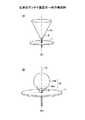
図1は従来のアンテナ装置を示す。図1(A)に示すアンテナ装置10は、地板11上に、円錐を反転させた形状の給電体12を配置した構成である。給電体12を構成する円錐は、その側面が軸線に対して角度θとなるように設定されている。この角度θによって所望能特性が得られる。 FIG. 1 shows a conventional antenna device. The
図1(B)に示すアンテナ装置20は、地板11上に、円錐体22aとそれに内接する球体22bとから構成される涙滴状の給電体22を配置した構成である。
従来の広帯域アンテナ装置は、平板状の地板上に円錐形状又は涙滴形状の給電体を配置した構成であるので、大型であり、小型化、薄型化が望まれていた。 The conventional broadband antenna device has a configuration in which a conical or teardrop-shaped power feeder is disposed on a flat base plate, so that it is large, and a reduction in size and thickness has been desired.
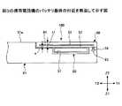
図2(A),(B)は本出願人が先に特願2005−378396号において出願した明細書及び図面に記載してあるUWB平面アンテナ装置30の基本構成であり、小型化、薄型化が図られている。 FIGS. 2A and 2B show the basic configuration of the UWB
UWB平面アンテナ装置30は、誘電体製の基板31の上面31aにホームベース形状のアンテナエレメントパターン32及びこのアンテナエレメントパターン32より延在してマイクロストリップ線路33が形成してあり、且つ、基板31の裏面31bにはマイクロストリップ線路33に対面する部分にグランドパターン34が形成してある構成である。 The UWB
このUWB平面アンテナ装置30は図1に示すアンテナ装置10,20に比較すると相当に小型化、薄型化されているけれども、これを携帯機器に設ける場合には、携帯機器にUWB平面アンテナ装置30が収まる大きさの空間を予め用意しておく必要があり、携帯機器の薄型化には不利であった。 Although the UWB
本発明は上記の点に鑑みてなされた携帯機器を提供することを目的とする。 An object of this invention is to provide the portable apparatus made in view of said point.
本発明は、バッテリが装着されて使用され、前記バッテリが装着された状態で該バッテリの表面がグランド電位となっている構成の携帯機器において、
該携帯機器の本体に取り付けられて前記バッテリを覆う蓋体を、平面状のアンテナエレメント部を有する構成とし、
前記蓋体が前記携帯機器の本体に取り付けられたときに、前記アンテナエレメント部が前記バッテリに接近して配置され、
前記バッテリの表面がグランドエレメントとして機能して、前記アンテナエレメント部と前記バッテリの表面とによって平面アンテナ装置が構成される構成としたことを特徴とする。The present invention is a portable device in which a battery is mounted and used, and the surface of the battery is at a ground potential when the battery is mounted.
The lid attached to the main body of the portable device and covering the battery is configured to have a planar antenna element portion,
When the lid is attached to the main body of the portable device, the antenna element portion is disposed close to the battery,
The surface of the battery functions as a ground element, and a planar antenna device is configured by the antenna element portion and the surface of the battery.
バッテリの面がグランドエレメントとして機能するようにして構成してあるため、完成品としての平面アンテナ装置を携帯機器に組み込んだ構成とした場合に比較して、携帯機器を、厚くすることなく構成出来る。 Since the battery surface functions as a ground element, the portable device can be configured without increasing the thickness compared to a configuration in which the planar antenna device as a finished product is incorporated in the portable device. .
また、バッテリが装着された状態でバッテリの表面がグランド電位となっていることを利用しているため、同軸ケーブルの接続が不要となり、その分構成が簡単となる。 In addition, since the fact that the surface of the battery is at the ground potential when the battery is mounted is used, the connection of the coaxial cable is unnecessary, and the configuration is simplified correspondingly.
次に本発明の実施の形態について説明する。 Next, an embodiment of the present invention will be described.
図3(A)、(B)は本発明の実施例1になる携帯電話機50を示す。携帯電話機50は、UWB平面アンテナ装置100を備えた構成である。このUWB平面アンテナ装置100は、バッテリ80の面(表面)83をグランドパターンとして利用した構成である。X1−X2は幅方向、Y1−Y2は長手方向、Z1−Z2は厚さ方向である。 3A and 3B show a
携帯電話機50は、本体51の上面51aに、スピーカ52、液晶パネル53、操作部54、マイク55が配置してあり、本体51の下面51bに、カメラ部56が設けてあり、更に、下面51bに、バッテリ収容部57及びコネクタ58が設けてあり、且つ、本体51の下面51b側において、バッテリ収容部57内にバッテリ80が装着してあり、バッテリ蓋体60がバッテリ80を覆っており、本体51の内側がシールド部材59によって囲まれている構成である。 In the
コネクタ58は、図7に示すように、UWB通信部70と電気的に接続してあり、且つ、図3(B)に示すように、バッテリ収容部57の近くに配置してある。 The
この携帯電話機50は、図7に示すように、従来の携帯電話機とは、UWB通信部70及びコネクタ58を有している点が相違する。操作部54から制御部71に指令が送られる。制御部71は、UWB通信部70と、電話通信部72と、画像処理部73とを制御する。電話部74は、スピーカ52及びマイク55を含む部分であり、電話通信部72によって動作され、UWB平面アンテナ装置100を通して通信が行なわれる。液晶パネル53は画像処理部71よりの信号によって駆動される。カメラ部56によって撮影された画像データは、画像処理部71によって処理され、液晶パネル53に表示され、また、UWB平面アンテナ装置100より送信される。バッテリ80は、制御部71、UWB通信部70、電話通信部72、画像処理部73等に駆動電圧Vccを供給する。 As shown in FIG. 7, the
バッテリ80は、図5に示すように、偏平な四角形状である鉄板製の箱体81の内部にバッテリ本体82が収まっている構成である。このバッテリ80は、バッテリ収容部57内に装着された状態で、制御部71等に電圧Vccを供給する。また、バッテリ80は、バッテリ収容部57内に装着された状態で、箱体81がシールド部材59と電気的に接続されている。図7中、点75は、箱体81がシールド部材59と電気的に接続されている箇所を示す。よって、図5に示すように、バッテリ80がバッテリ収容部57内に装着された状態で、Z2側には、平面であり、四角形であり、電位がグランドレベルとなっている面83が露出している。 As shown in FIG. 5, the
図4及び図5に示すように、バッテリ蓋体60は、板状の樹脂成形部品であり、内部に、アンテナフィルム90がインサート成形してある構成である。アンテナフィルム90は、フィルムに、ホームベース形状のアンテナエレメント部91と、このアンテナエレメント部91の突部(給電点)91aの部分から延びている線エレメント部92とが形成してあり、線エレメント部92の端のコンタクト部93を有する構成である。コンタクト部93は、線エレメント部92に対して直角に曲げてあり、バッテリ蓋体60の下面より突き出ている。アンテナエレメント部91の突部(給電点)91aの開き角度θは約60度である
バッテリ蓋体60のサイズは、上記のバッテリ収容部57に対応するサイズよりも大きいサイズであり、線エレメント部92の部分が上記のバッテリ収容部57に対応する部分に相当し、アンテナエレメント部91の部分が、上記のバッテリ収容部57に対応する部分よりもY2方向に延びている。このバッテリ蓋体60は、アンテナエレメント部91がバッテリ収容部57の直ぐY2側に位置する配置でもって本体51に取り付けられる。As shown in FIG.4 and FIG.5, the
図4に示すように、バッテリ80がバッテリ収容部57内に装着され、バッテリ蓋体60がバッテリ80を覆うように本体51の下面51bに取り付けられた状態において、アンテナエレメント部材90と、バッテリ80の面83とは、図6に示す位置関係となる。即ち、アンテナエレメント部91は、面83に対しては、面83よりZ2方向にバッテリ蓋体60の厚さt1の1/2の寸法a離れた位置であって、面82の直ぐY2側の位置に、即ち、Z2側から見て、突部91aが面83のY2側の辺83aに略一致する位置に、面83と平行に位置している。線エレメント部92は、面83よりZ2方向に寸法a離れた位置に維持されて、面83を横切っている。また、コンタクト部93がコネクタ58に接続してある。上記の寸法aは1mm以下である。 As shown in FIG. 4, in a state where the
よって、面82がグランドエレメントとして機能して、アンテナエレメント部91と、面82と、線エレメント部92とによって、UWB平面アンテナ装置100が構成される。ここで、バッテリ80は、バッテリ収容部57内に装着された状態で、箱体81がシールド部材59と電気的に接続されているため、同軸ケーブルをUWB平面アンテナ装置100に接続することは不要となり、その分、構成が簡単となっている。 Therefore, the
上記の携帯電話機50は、UWB平面アンテナ装置100が、バッテリ80の面83がグランドエレメントとして機能するようにして構成してあるため、完成品としてのUWB平面アンテナ装置を組み込んだ構成の携帯電話機に比較して小型に、特に厚さを薄くして構成してある。 Since the UWB
図8は本発明の実施例2になるデジタルカメラ110を示す。デジタルカメラ110は、本体111のレンズ(図示せず)とは反対側の面111bに、液晶パネル112、バッテリ収容部113及びコネクタ114を有し、バッテリ収容部113に偏平な四角形状のバッテリ80Aが装着してあり、内部に、アンテナフィルム90Aがインサート成形してあるバッテリ蓋体60Aが、本体111に取り付けてあり、バッテリ80Aを覆っている構成である。また、コンタクト部93Aがコネクタ114に接続してある。 FIG. 8 shows a
バッテリ80Aの面83Aがグランドエレメントとして機能して、アンテナエレメント部91Aと、面83Aと、線エレメント部92Aとによって、UWB平面アンテナ装置100Aが構成されている。 The
上記のデジタルカメラ110は、専用のグランドエレメントを有するUWB平面アンテナ装置を備えた構成のデジタルカメラに比較して小型に、特に厚さを薄くして構成してある。 The above-described
50 携帯電話機
51 本体
52 スピーカ
53 液晶パネル
54 操作部
55 マイク
56 カメラ部
57 バッテリ収容部
58 コネクタ
59 シールド部材
60 バッテリ蓋体
70 UWB通信部
71 制御部
80 バッテリ
81 鉄板製の箱体
82 バッテリ本体
83 面(表面)
90 アンテナフィルム
91 アンテナエレメント部
92 線エレメント部
93 コンタクト部
100、100A UWB平面アンテナ装置
110 デジタルカメラDESCRIPTION OF
DESCRIPTION OF
Claims (3)
Translated fromJapanese該携帯機器の本体に取り付けられて前記バッテリを覆う蓋体を、平面状のアンテナエレメント部を有する構成とし、
前記蓋体が前記携帯機器の本体に取り付けられたときに、前記アンテナエレメント部が前記バッテリに接近して配置され、
前記バッテリの表面がグランドエレメントとして機能して、前記アンテナエレメント部と前記バッテリの表面とによって平面アンテナ装置が構成される構成としたことを特徴とする携帯機器。In a portable device having a configuration in which a battery is used and the surface of the battery is at a ground potential when the battery is installed,
The lid attached to the main body of the portable device and covering the battery is configured to have a planar antenna element portion,
When the lid is attached to the main body of the portable device, the antenna element portion is disposed close to the battery,
A portable device in which the surface of the battery functions as a ground element and a planar antenna device is configured by the antenna element portion and the surface of the battery.
前記バッテリを覆う蓋体は、前記アンテナエレメント部を内部に有する構成であることを特徴とする携帯機器。The mobile device according to claim 1,
The lid that covers the battery is configured to have the antenna element portion therein.
前記アンテナエレメントと、携帯機器に装着されたバッテリとが接近して配置してあり、
前記バッテリの表面を前記グランドエレメントとして利用した構成としたことを特徴とする平面アンテナ装置。In a planar antenna device in which both a planar antenna element and a ground element are arranged close to each other,
The antenna element and the battery attached to the portable device are arranged close to each other,
A planar antenna device characterized in that the surface of the battery is used as the ground element.
Priority Applications (2)
| Application Number | Priority Date | Filing Date | Title |
|---|---|---|---|
| JP2006108872AJP4783194B2 (en) | 2006-04-11 | 2006-04-11 | Portable device |
| US11/528,313US8326376B2 (en) | 2006-04-11 | 2006-09-28 | Portable apparatus |
Applications Claiming Priority (1)
| Application Number | Priority Date | Filing Date | Title |
|---|---|---|---|
| JP2006108872AJP4783194B2 (en) | 2006-04-11 | 2006-04-11 | Portable device |
Publications (2)
| Publication Number | Publication Date |
|---|---|
| JP2007282102Atrue JP2007282102A (en) | 2007-10-25 |
| JP4783194B2 JP4783194B2 (en) | 2011-09-28 |
Family
ID=38575986
Family Applications (1)
| Application Number | Title | Priority Date | Filing Date |
|---|---|---|---|
| JP2006108872AExpired - Fee RelatedJP4783194B2 (en) | 2006-04-11 | 2006-04-11 | Portable device |
Country Status (2)
| Country | Link |
|---|---|
| US (1) | US8326376B2 (en) |
| JP (1) | JP4783194B2 (en) |
Cited By (4)
| Publication number | Priority date | Publication date | Assignee | Title |
|---|---|---|---|---|
| JP2012182727A (en)* | 2011-03-02 | 2012-09-20 | Fujikura Ltd | Antenna device and planar type radio device |
| KR101433669B1 (en)* | 2012-01-20 | 2014-08-25 | 주식회사 엘지화학 | Battery Module Having Planar Inverted-F Antenna |
| JP2014179614A (en)* | 2013-03-13 | 2014-09-25 | Samsung Electronics Co Ltd | Electronic device |
| JP2020513220A (en)* | 2016-11-01 | 2020-05-07 | デュラセル、ユーエス、オペレーションズ、インコーポレーテッド | Positive electrode Battery terminal Antenna ground plane |
Families Citing this family (10)
| Publication number | Priority date | Publication date | Assignee | Title |
|---|---|---|---|---|
| US20080194288A1 (en)* | 2007-02-12 | 2008-08-14 | Broadcom Corporation | Integrated circuit including packet network transceivers and fm receiver with fm antenna control |
| US8501342B2 (en)* | 2007-04-11 | 2013-08-06 | Samsung Sdi Co., Ltd. | Rechargeable battery with an antenna assembly |
| KR101127101B1 (en)* | 2009-02-10 | 2012-03-23 | 제일모직주식회사 | In-mold type roof antena and it's manufacturing method |
| KR20110003854A (en)* | 2009-07-06 | 2011-01-13 | 엘지전자 주식회사 | Mobile terminal |
| CN102055063B (en)* | 2009-11-06 | 2013-09-04 | 富港电子(昆山)有限公司 | Hand-held device with short-range wireless communication antenna and assembly method thereof |
| KR101240273B1 (en)* | 2011-06-01 | 2013-03-11 | 엘지전자 주식회사 | Mobile terminal |
| KR101863924B1 (en)* | 2011-06-21 | 2018-06-01 | 엘지전자 주식회사 | Mobile terminal |
| DE102011107303A1 (en)* | 2011-07-06 | 2013-01-10 | Techem Energy Services Gmbh | Device for holding an antenna and a battery |
| PL2774212T3 (en) | 2011-11-03 | 2017-07-31 | Nokia Technologies Oy | Apparatus for wireless communication |
| EP3110174B1 (en)* | 2015-06-24 | 2021-02-17 | Oticon A/s | Hearing device including antenna unit and shielded transmission line |
Citations (6)
| Publication number | Priority date | Publication date | Assignee | Title |
|---|---|---|---|---|
| JPH10190331A (en)* | 1996-12-27 | 1998-07-21 | Nec Shizuoka Ltd | Antenna system for mobile communication |
| JP2000013119A (en)* | 1998-06-25 | 2000-01-14 | Matsushita Electric Ind Co Ltd | Antenna device for mobile communication terminal |
| JP2000013118A (en)* | 1998-06-25 | 2000-01-14 | Matsushita Electric Ind Co Ltd | Antenna device for mobile communication terminal |
| JP2000209013A (en)* | 1999-01-14 | 2000-07-28 | Nec Saitama Ltd | Mobile radio terminal and built-in antenna |
| JP2004328693A (en)* | 2002-11-27 | 2004-11-18 | Taiyo Yuden Co Ltd | Antenna and dielectric substrate for antenna |
| JP2005110123A (en)* | 2003-10-01 | 2005-04-21 | Alps Electric Co Ltd | Pattern antenna |
Family Cites Families (15)
| Publication number | Priority date | Publication date | Assignee | Title |
|---|---|---|---|---|
| US4780724A (en)* | 1986-04-18 | 1988-10-25 | General Electric Company | Antenna with integral tuning element |
| US5736965A (en)* | 1996-02-07 | 1998-04-07 | Lutron Electronics Co. Inc. | Compact radio frequency transmitting and receiving antenna and control device employing same |
| JP3039951U (en)* | 1996-11-25 | 1997-08-05 | 有限会社 夢創 | Planar antenna device for mobile communication equipment |
| JP2000196327A (en) | 1998-12-25 | 2000-07-14 | Harada Ind Co Ltd | Film antenna device |
| US6380899B1 (en)* | 2000-09-20 | 2002-04-30 | 3Com Corporation | Case with communication module having a passive radiator for a handheld computer system |
| US6421016B1 (en)* | 2000-10-23 | 2002-07-16 | Motorola, Inc. | Antenna system with channeled RF currents |
| DE10156073B4 (en)* | 2001-11-16 | 2008-08-21 | Giesecke & Devrient Gmbh | Foil battery for portable data carriers with antenna function |
| US20040204188A1 (en)* | 2002-04-04 | 2004-10-14 | Stevens Mark Anthony | Grounding system for a cell phone |
| US7319433B2 (en)* | 2002-06-13 | 2008-01-15 | Sony Ericsson Mobile Communications Ab | Wideband antenna device with extended ground plane in a portable device |
| JP2006517370A (en)* | 2003-02-04 | 2006-07-20 | コーニンクレッカ フィリップス エレクトロニクス エヌ ヴィ | Planar high frequency or microwave antenna |
| JPWO2005004342A1 (en)* | 2003-07-08 | 2006-08-17 | 富士通株式会社 | Communication terminal device and power supply method |
| KR100740083B1 (en)* | 2004-11-24 | 2007-07-16 | 삼성전자주식회사 | Built-in antenna device of portable wireless terminal |
| US20060281500A1 (en)* | 2005-06-14 | 2006-12-14 | Inventec Appliances Corp. | Mobile telecommunication apparatus having antenna assembly compatible with different communication protocols |
| JP4607009B2 (en)* | 2005-12-28 | 2011-01-05 | 富士通コンポーネント株式会社 | Antenna device |
| US7327318B2 (en)* | 2006-02-28 | 2008-02-05 | Mti Wireless Edge, Ltd. | Ultra wide band flat antenna |
- 2006
- 2006-04-11JPJP2006108872Apatent/JP4783194B2/ennot_activeExpired - Fee Related
- 2006-09-28USUS11/528,313patent/US8326376B2/ennot_activeExpired - Fee Related
Patent Citations (6)
| Publication number | Priority date | Publication date | Assignee | Title |
|---|---|---|---|---|
| JPH10190331A (en)* | 1996-12-27 | 1998-07-21 | Nec Shizuoka Ltd | Antenna system for mobile communication |
| JP2000013119A (en)* | 1998-06-25 | 2000-01-14 | Matsushita Electric Ind Co Ltd | Antenna device for mobile communication terminal |
| JP2000013118A (en)* | 1998-06-25 | 2000-01-14 | Matsushita Electric Ind Co Ltd | Antenna device for mobile communication terminal |
| JP2000209013A (en)* | 1999-01-14 | 2000-07-28 | Nec Saitama Ltd | Mobile radio terminal and built-in antenna |
| JP2004328693A (en)* | 2002-11-27 | 2004-11-18 | Taiyo Yuden Co Ltd | Antenna and dielectric substrate for antenna |
| JP2005110123A (en)* | 2003-10-01 | 2005-04-21 | Alps Electric Co Ltd | Pattern antenna |
Cited By (6)
| Publication number | Priority date | Publication date | Assignee | Title |
|---|---|---|---|---|
| JP2012182727A (en)* | 2011-03-02 | 2012-09-20 | Fujikura Ltd | Antenna device and planar type radio device |
| KR101433669B1 (en)* | 2012-01-20 | 2014-08-25 | 주식회사 엘지화학 | Battery Module Having Planar Inverted-F Antenna |
| JP2014179614A (en)* | 2013-03-13 | 2014-09-25 | Samsung Electronics Co Ltd | Electronic device |
| TWI645617B (en)* | 2013-03-13 | 2018-12-21 | 三星電子股份有限公司 | Electronic device |
| JP2020513220A (en)* | 2016-11-01 | 2020-05-07 | デュラセル、ユーエス、オペレーションズ、インコーポレーテッド | Positive electrode Battery terminal Antenna ground plane |
| JP7064492B2 (en) | 2016-11-01 | 2022-05-10 | デュラセル、ユーエス、オペレーションズ、インコーポレーテッド | Ground plane of positive electrode battery terminal antenna |
Also Published As
| Publication number | Publication date |
|---|---|
| US20070238492A1 (en) | 2007-10-11 |
| US8326376B2 (en) | 2012-12-04 |
| JP4783194B2 (en) | 2011-09-28 |
Similar Documents
| Publication | Publication Date | Title |
|---|---|---|
| JP4783194B2 (en) | Portable device | |
| KR102176373B1 (en) | Mobile terminal | |
| CN109546295B (en) | electronic device | |
| CN106067826B (en) | Mobile terminal | |
| JP4633605B2 (en) | ANTENNA DEVICE AND ELECTRONIC DEVICE, ELECTRONIC CAMERA, ELECTRONIC CAMERA LIGHT EMITTING DEVICE, AND PERIPHERAL DEVICE | |
| CN111492644B (en) | Antenna device and mobile terminal with same | |
| JP5005508B2 (en) | Antenna device mounting structure | |
| JP4754601B2 (en) | Antenna device | |
| KR20160034042A (en) | Mobile terminal | |
| US8406828B2 (en) | Mobile terminal | |
| JP5032962B2 (en) | Antenna device | |
| US8525740B2 (en) | Mobile terminal | |
| CN104838539A (en) | Loop antenna having a parasitically coupled element | |
| KR20180122231A (en) | Mobile terminal | |
| KR20190036438A (en) | Electronic device | |
| CN108281767A (en) | Antenna module and electronic equipment | |
| CN104538741A (en) | Slot antenna and electronic equipment with conducting border | |
| CN108550979A (en) | Antenna assembly, housing assembly and electronic equipment | |
| KR20200089330A (en) | Antenna device and mobile terminal having same | |
| KR102192822B1 (en) | Mobile terminal | |
| JP2008259102A (en) | Antenna unit | |
| KR20160084745A (en) | Antenna apparatus and mobile terminal having the same | |
| KR20130106213A (en) | Mobile terminal | |
| CN112821046B (en) | Antenna structure and terminal equipment | |
| US7692589B2 (en) | Antenna device, electronic device, and method of manufacturing antenna device |
Legal Events
| Date | Code | Title | Description |
|---|---|---|---|
| A621 | Written request for application examination | Free format text:JAPANESE INTERMEDIATE CODE: A621 Effective date:20090413 | |
| A977 | Report on retrieval | Free format text:JAPANESE INTERMEDIATE CODE: A971007 Effective date:20110120 | |
| A131 | Notification of reasons for refusal | Free format text:JAPANESE INTERMEDIATE CODE: A131 Effective date:20110222 | |
| A521 | Written amendment | Free format text:JAPANESE INTERMEDIATE CODE: A523 Effective date:20110304 | |
| TRDD | Decision of grant or rejection written | ||
| A01 | Written decision to grant a patent or to grant a registration (utility model) | Free format text:JAPANESE INTERMEDIATE CODE: A01 Effective date:20110705 | |
| A01 | Written decision to grant a patent or to grant a registration (utility model) | Free format text:JAPANESE INTERMEDIATE CODE: A01 | |
| A61 | First payment of annual fees (during grant procedure) | Free format text:JAPANESE INTERMEDIATE CODE: A61 Effective date:20110708 | |
| FPAY | Renewal fee payment (event date is renewal date of database) | Free format text:PAYMENT UNTIL: 20140715 Year of fee payment:3 | |
| R150 | Certificate of patent or registration of utility model | Free format text:JAPANESE INTERMEDIATE CODE: R150 | |
| R250 | Receipt of annual fees | Free format text:JAPANESE INTERMEDIATE CODE: R250 | |
| S531 | Written request for registration of change of domicile | Free format text:JAPANESE INTERMEDIATE CODE: R313531 | |
| R350 | Written notification of registration of transfer | Free format text:JAPANESE INTERMEDIATE CODE: R350 | |
| R250 | Receipt of annual fees | Free format text:JAPANESE INTERMEDIATE CODE: R250 | |
| R250 | Receipt of annual fees | Free format text:JAPANESE INTERMEDIATE CODE: R250 | |
| LAPS | Cancellation because of no payment of annual fees |