JP2007280414A - Receiver and content storage device - Google Patents
Receiver and content storage deviceDownload PDFInfo
- Publication number
- JP2007280414A JP2007280414AJP2007143397AJP2007143397AJP2007280414AJP 2007280414 AJP2007280414 AJP 2007280414AJP 2007143397 AJP2007143397 AJP 2007143397AJP 2007143397 AJP2007143397 AJP 2007143397AJP 2007280414 AJP2007280414 AJP 2007280414A
- Authority
- JP
- Japan
- Prior art keywords
- portable memory
- card
- contacts
- memory card
- contact
- Prior art date
- Legal status (The legal status is an assumption and is not a legal conclusion. Google has not performed a legal analysis and makes no representation as to the accuracy of the status listed.)
- Pending
Links
Images


Classifications
- G—PHYSICS
- G06—COMPUTING OR CALCULATING; COUNTING
- G06K—GRAPHICAL DATA READING; PRESENTATION OF DATA; RECORD CARRIERS; HANDLING RECORD CARRIERS
- G06K7/00—Methods or arrangements for sensing record carriers, e.g. for reading patterns
- G06K7/0013—Methods or arrangements for sensing record carriers, e.g. for reading patterns by galvanic contacts, e.g. card connectors for ISO-7816 compliant smart cards or memory cards, e.g. SD card readers
- G06K7/0034—Methods or arrangements for sensing record carriers, e.g. for reading patterns by galvanic contacts, e.g. card connectors for ISO-7816 compliant smart cards or memory cards, e.g. SD card readers the connector being capable of simultaneously receiving a plurality of cards in the same insertion slot
- G—PHYSICS
- G06—COMPUTING OR CALCULATING; COUNTING
- G06K—GRAPHICAL DATA READING; PRESENTATION OF DATA; RECORD CARRIERS; HANDLING RECORD CARRIERS
- G06K19/00—Record carriers for use with machines and with at least a part designed to carry digital markings
- G06K19/06—Record carriers for use with machines and with at least a part designed to carry digital markings characterised by the kind of the digital marking, e.g. shape, nature, code
- G06K19/067—Record carriers with conductive marks, printed circuits or semiconductor circuit elements, e.g. credit or identity cards also with resonating or responding marks without active components
- G06K19/07—Record carriers with conductive marks, printed circuits or semiconductor circuit elements, e.g. credit or identity cards also with resonating or responding marks without active components with integrated circuit chips
- G06K19/077—Constructional details, e.g. mounting of circuits in the carrier
- G06K19/07743—External electrical contacts
- G—PHYSICS
- G06—COMPUTING OR CALCULATING; COUNTING
- G06K—GRAPHICAL DATA READING; PRESENTATION OF DATA; RECORD CARRIERS; HANDLING RECORD CARRIERS
- G06K7/00—Methods or arrangements for sensing record carriers, e.g. for reading patterns
- G06K7/0013—Methods or arrangements for sensing record carriers, e.g. for reading patterns by galvanic contacts, e.g. card connectors for ISO-7816 compliant smart cards or memory cards, e.g. SD card readers
- G06K7/0021—Methods or arrangements for sensing record carriers, e.g. for reading patterns by galvanic contacts, e.g. card connectors for ISO-7816 compliant smart cards or memory cards, e.g. SD card readers for reading/sensing record carriers having surface contacts
Landscapes
- Engineering & Computer Science (AREA)
- Physics & Mathematics (AREA)
- General Physics & Mathematics (AREA)
- Theoretical Computer Science (AREA)
- Artificial Intelligence (AREA)
- Computer Vision & Pattern Recognition (AREA)
- Computer Hardware Design (AREA)
- Microelectronics & Electronic Packaging (AREA)
- Credit Cards Or The Like (AREA)
- Coupling Device And Connection With Printed Circuit (AREA)
Abstract
Description
Translated fromJapanese本発明は、データ記憶に関し、特に、データの記憶および再生のために利用されるポータブルメモリ記憶カードを備えたレシーバとコンテンツ記憶装置とに関する。 The present invention relates to data storage, and more particularly, to a receiver and portable storage device with a portable memory storage card used for data storage and playback.
多くの人々が、映画、音楽、ゲーム、ソフトウェアまたは他のコンテンツが記憶される、コンパクトディスク、ビデオテープ、ゲームソフトウェアカートリッジまたはディスク、DVD、レーザディスク等の媒体のコレクションを有している。これらコレクションが増大するに従い、それらのためのスペースを見つけることはしばしば難しい問題となる。更に、媒体が異なると通常は必要なプレイヤも異なり、それらは場所を取り、購入するには高価である可能性がある。大抵のかかるプレイヤは、可動部品と複雑な回路とを有する。更に、プレイヤが受付けることができる独立した媒体項目の数が増大するに従い、可動部品の数と結果としての誤動作の可能性とがしばしば増大する。例えば、DVDプレイヤによっては、2つの別々のDVDを収容することができるものがあり、その場合、各DVDは別々の駆動機構により別々のトレイに配置される。プレイヤにおける機構の数が2倍になることにより、プレイヤの信頼性は低減し、そのコストは増大する。他の例として、コンパクトディスクプレイヤによっては、様々な機構を使用して複数のコンパクトディスクを挿入することができるものがある。しかしながら、これら機構は各々、機械的に、ディスクを再生するためにハブおよびレーザを有する特定の駆動場所に特定のディスクを配置し、その後他のディスクが再生される時はディスクをその場所から移動させなければならない。 Many people have collections of media such as compact discs, video tapes, game software cartridges or discs, DVDs, laser discs, etc., on which movies, music, games, software or other content is stored. As these collections grow, finding space for them is often a difficult problem. In addition, different media usually require different players, which can be expensive to take up and purchase. Most such players have moving parts and complex circuits. Furthermore, as the number of independent media items that a player can accept increases, the number of moving parts and the resulting potential for malfunctions often increase. For example, some DVD players can accommodate two separate DVDs, in which case each DVD is placed on a separate tray by a separate drive mechanism. By doubling the number of mechanisms in the player, the player's reliability is reduced and its cost is increased. As another example, some compact disc players can insert a plurality of compact discs using various mechanisms. However, each of these mechanisms mechanically places a particular disk at a particular drive location with a hub and laser to play the disk, and then moves the disk from that location when another disk is played. I have to let it.
媒体のサイズを縮小するために、より小さいメモリ記憶装置が開発された。かかるメモリ記憶装置には、フラッシュメモリカード、PCMCIAカード、Smart Media(登録商標)(スマートメディア)カード、SecureDigital(セキュアデジタル)カード、MMC Card(Multi−Media Card(マルチメディアカード))およびソニー株式会社のMemory Stick(メモリースティック)が含まれる。これらメモリ記憶装置は、先の装置より小さくなり得るが、まだ集合的にまとめて取り扱い保管することが困難である。実際に、これらメモリ記憶装置は、サイズが小さいことにより、置き忘れられるか遺失される可能性が高くなる。そこで、本発明は、複数のカードをまとめて取り扱う利便性が高い構成を提供することを目的とする。 In order to reduce the size of the media, smaller memory storage devices have been developed. Such memory storage devices include flash memory cards, PCMCIA cards, Smart Media (registered trademark) (smart media) cards, SecureDigital (secure digital) cards, MMC Card (Multi-Media Card (multimedia card)) and Sony Corporation. Memory Stick is included. These memory storage devices can be smaller than previous devices, but are still difficult to handle and store collectively. In fact, these memory storage devices are likely to be misplaced or lost due to their small size. Accordingly, an object of the present invention is to provide a configuration that is highly convenient for handling a plurality of cards together.
各側面に接点を有するポータブルメモリ記憶カードを、カードに記憶された情報にアクセスすることができるレシーバに積み重ねることができ、それによりそれらカードのコンパクトで効率的な記憶および使用が可能となる。 Portable memory storage cards with contacts on each side can be stacked on a receiver that can access the information stored on the cards, thereby enabling compact and efficient storage and use of the cards.
本発明の1つの態様では、ポータブルメモリ記憶カードは、反転可能(リバーシブル)であるように、両面に接点を有する。メモリ記憶カードは、音声、映像、ソフトウェアまたは他のコンテンツを記憶するように適合させられる。 In one aspect of the invention, the portable memory storage card has contacts on both sides so that it is reversible. The memory storage card is adapted to store audio, video, software or other content.
本発明の他の態様では、カード用のレシーバはまた、カードに記憶される情報へのアクセスを可能にする装置としての役割も果たす。内部に任意に多数のカードが積み重ねられ得る格納キャビティの一端には、一組の接点が設けられ、それらの接点が接触してバスを形成するようになっている。積み重ねられたカードが一組の接点に対して付勢されることにより、格納キャビティの一組の接点と隣接するカードの接点との間の物理的接触が確立される。隣接するカードとの接触によってカードを互いに接続することができることにより、カードからのデータアクセスが簡易化される。カードの両面に接点が設けられるため、カードは任意に厚くても良く、すべてが同じ厚さである必要はない。データは、カードによって形成されるバスに沿って、キャビティの少なくとも1つの接点を通って伝わる。従って、レシーバは、プレイヤも兼ねるため、カードに記憶されたコンテンツにアクセスするために別個のプレイヤが必要ではない。更に、カードは、再生されるレシーバから取除かれる必要がないため、通常の使用中に遺失されるかまたは置き忘れられる可能性が低くなる。 In another aspect of the invention, the receiver for the card also serves as a device that allows access to information stored on the card. One end of the storage cavity in which an arbitrarily large number of cards can be stacked is provided with a set of contacts, which contact to form a bus. The stacked cards are biased against a set of contacts to establish physical contact between the set of contacts in the storage cavity and the contacts of adjacent cards. Since the cards can be connected to each other by contact with adjacent cards, data access from the cards is simplified. Since contacts are provided on both sides of the card, the card may be arbitrarily thick and not all have the same thickness. Data travels along the bus formed by the card through at least one contact in the cavity. Therefore, since the receiver also serves as a player, a separate player is not required to access the content stored on the card. Further, since the card does not need to be removed from the replayed receiver, it is less likely to be lost or misplaced during normal use.
本発明の他の態様では、カードは各々少なくとも1つの位置合せガイドを有する。位置合せガイドは、カードがレシーバのキャビティに格納された時に隣接するカードの互いに対する移動を制限することにより、隣接するカード間の接点の位置合せを確実にする一助となる。 In another aspect of the invention, each card has at least one alignment guide. The alignment guide helps to ensure the alignment of the contacts between adjacent cards by limiting the movement of adjacent cards relative to each other when the cards are stored in the receiver cavity.
本発明は、添付図面と共に下の詳細な説明を考慮することにより、より十分に理解されよう。 The present invention will be more fully understood upon consideration of the detailed description below in conjunction with the accompanying drawings.
異なる図面における同じ参照符号の使用は、同様のまたは全く同じ項目を示す。 The use of the same reference symbols in different drawings indicates similar or identical items.
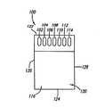
図1ないし図3を参照すると、ポータブルメモリ記憶カード100が示されている。一実施形態では、ポータブルメモリ記憶カード100は、実質的に中空の内部304を備えた実質的に箱型の本体120を有する。ポータブルメモリ記憶カード100の本体120は、実質的に同じ表面積を有し本体120上に互いに対向しかつ実質的に平行に配置された、第1面116と第2面118とを有する。第1面116と第2面118とは、本体120の最大表面積を有する。第1面116と第2面118とは、各々が第1面116と第2面118との両方に対して実質的に直角に配置された、上面122および底面124と、左側面126および右側面128と、によって接続される。上面122と底面124とは共に、実質的に同じ表面積を有し、互いに対向しかつ実質的に平行に本体120に配置される。更に、左側面126と右側面128とは共に、実質的に同じ表面積を有し、互いに対向しかつ実質的に平行に本体120に配置される。 With reference to FIGS. 1-3, a portable
ポータブルメモリ記憶カード100の本体120は、実質的に剛性かつ耐久性のある材料かまたはかかる材料の組合せから構成されても良い。一実施形態では、本体120は実質的に非導電性である。本体120は、プラスチック、ポリカーボネート、セラミックあるいは1つまたは複数の他の適当な材料から構成されても良い。本体120の特定の材料組成は、本発明には重要ではない。 The
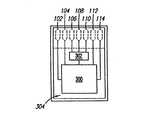
本体120の中空の内部304内には、メモリ記憶ユニット300が配置される。メモリ記憶ユニット300は、データを記憶することができる、あらゆるタイプの装置または装置の組合せであり得る。例えば、メモリ記憶ユニット300は、ソリッドステートメモリ、リライタブル光ドライブ、リードオンリー光ドライブまたは他の装置であり得る。一実施形態では、メモリ記憶ユニット300はリードオンリであり、それは、メモリ記憶ユニット300が、1回だけ書込まれるデータを受取るのに適するように構成され、その後メモリ記憶ユニット300からはデータを読出すことしかできないことを意味する。他の実施形態では、メモリ記憶ユニット300はリライタブルであり、それは、メモリ記憶ユニット300に対し、すでに存在するデータに追加してまたはその代りに、データを複数回書込むことができることを意味する。メモリ記憶ユニット300として使用される特定の装置は、本発明には重要ではない。 A
一実施形態では、メモリ記憶ユニット300には、電気インタフェースモジュール302が電気的に接続される。一実施形態では、電気インタフェースモジュール302はバッファを含み、特定用途向け集積回路(ASIC)、フィールドプログラマブルゲートアレイ(FPGA:現場でプログラム可能な論理列)または他のかかる装置である。バッファは、メモリ記憶ユニット300とは別のメモリを含むかまたはそれに電気的に接続されてもよい。他の実施形態では、バッファは、メモリ記憶ユニット300の一部として含まれる。バスとメモリ記憶ユニット300等のメモリとの間のバッファは、本技術分野において標準的である。電気インタフェースモジュール302は、他の回路を含んでも良く、および/または異なるかまたは追加の機能を実行しても良い。例えば、電気インタフェースモジュール302は、レジスタ、電圧プロテクタ、電源、プロセッサ、バスコントローラ、暗号化ロジック、認証ロジックまたは他のロジックを含んでも良い。更に、異なる機能を実行するために複数の電気インタフェースモジュール302が設けられても良い。 In one embodiment, the
ポータブルメモリ記憶カード100の第1面116には、多数の接点102〜114が設けられる。望ましい場合は、それより多いかまたは少ない接点が設けられても良い。ひとまとめにして、接点102〜114のセットを、本技術分野における標準の専門語であるコネクタと呼ぶことができる。一実施形態において、第1接点102、第2接点104、第3接点112および第4接点114は、トレース、ワイヤまたは他の導体を介して電気インタフェースモジュール302に電気的に接続される。第1接点102、第2接点104、第3接点112および第4接点114は、まとめてデータ接点102、104、112、114と呼ばれ、ポータブルメモリ記憶カード100に対しおよび/またはポータブルメモリ記憶カード100からデータを伝達する。第5接点106および第6接点110は、トレース、ワイヤまたは他の導体を介して、メモリ記憶ユニット300に電気的に接続される。第5接点106および第6接点110は、まとめて電源用接点106、110と呼ばれ、ポータブルメモリ記憶カード100内の回路に電力を伝える。電源用接点106、110は、電気インタフェースモジュール302にも接続されるか、またはメモリ記憶ユニット300の代りに電気インタフェースモジュール302に接続されても良く、あるいは、電気インタフェースモジュール302は、メモリ記憶ユニット300を介して電源を受取っても良い。第7接点108は、トレース、ワイヤまたは他の導体を介して、メモリ記憶ユニット300に電気的に接続される。第7接点108は接地接点であり、ポータブルメモリ記憶カード100の接地を実現する。接地接点108は、メモリ記憶ユニット300、もしくは電気インタフェースモジュール302またはそれら両方に接続されても良い。 A large number of contacts 102-114 are provided on the
一実施形態では、第1面116の各接点102〜114は、コンタクトパッドである。かかるコンタクトパッドは、ポータブルメモリ記憶カード100の内部の金属トレースまたはワイヤと外部回路との間の接点を提供する、第1面116上の金属被覆された領域であり、本技術分野では標準的である。コンタクトパッドは、後により詳細に説明するように、これらのコンタクトパッドと隣接するポータブルメモリ記憶カード100のコンタクトパッドとの間の接続を向上させるために、第1面116の表面をわずかに越えるように延在しても良い。代りに、コンタクトパッドは、所望の場合は、第1面116の表面と実質的に同一平面であっても良い。 In one embodiment, each contact 102-114 of the
他の実施形態では、各接点102〜114は、金属板、棒、板ばね、重ね板ばねまたは他の実質的に平坦な導体である。接点102〜114は各々、ばねであるか、または本体120内のばね(図示せず)に連結されても良い。各接点102〜114は、個別のばねに連結されても良く、あるいは、接点102〜114のうちの2つ以上が同じばねに接続されても良い。この実施形態では、各接点102〜114は、ポータブルメモリ記憶装置100の本体120から外側へと付勢される。このため、各接点102〜114は、外面に対して配置される時に、本体に向かって戻る方向に撓むことができるように動くことができる。この可撓性により、接点102〜114は、接点102〜114の表面が実質的に第1面116と同一平面である位置まで撓むことができる。このように、接点102〜114は、後により詳細に説明するように、個々のポータブルメモリ記憶装置100を複数個一緒に積み重ねることができることの妨げとならない。 In other embodiments, each contact 102-114 is a metal plate, bar, leaf spring, lap leaf spring or other substantially flat conductor. Each of the contacts 102-114 is a spring or may be coupled to a spring (not shown) in the
一実施形態では、接点102〜114は、第1面116上に対称的に配置される。対称の1つの例として、接地接点108が、接点102〜114の列の中心に配置される。一方の電源用接点106が接地接点108の一方の側に配置され、他方の電源用接点110が接地接点108の反対側に配置される。2つのデータ接点102、104は、1つの電源用接点106に隣接するように配置され、他方のデータ接点112、114は、他方の電源用接点110に隣接するように配置される。このように接点102〜114は、左右対称の列を形成する。 In one embodiment, the contacts 102-114 are symmetrically disposed on the
接点102〜114は、対称的であるために本明細書で説明する特定の順序で配置される必要はなく、望ましい場合は、接点102〜114の他の構成も利用され得る。更に、接点102〜114は、左右対称であるように1列に配置される必要はない。例えば、接点102〜114は、左右対称を保持しながら水平線に対して互い違いにされても良い。他の実施形態では、接点102〜114は、左右対称ではなく放射対称の構成で配置されても良い。1つの放射状に対称的な構成の実施の形態として、接点102〜114は円の周辺に沿って配置され得る。 The contacts 102-114 need not be arranged in the particular order described herein to be symmetric, and other configurations of the contacts 102-114 may be utilized if desired. Furthermore, the contacts 102-114 need not be arranged in a row so as to be symmetrical. For example, the
また、ポータブルメモリ記憶装置100の本体120の第2面118も、複数の接点202〜214を有する。第2面118の接点202〜214の特性は、第1面116の接点102〜114に関して上述したものと実質的に同じである。第2面118には、第1面116と同じ数の接点202〜214が設けられる。一実施形態では、第2面118において、第1接点202、第2接点204、第3接点212および第4接点214は、トレース、ワイヤまたは他の導体を介して電気インタフェースモジュール302に電気的に接続される。第1接点202、第2接点204、第3接点212および第4接点214は、まとめてデータ接点202、204、212、214と呼ばれ、ポータブルメモリ記憶カード100におよび/またはポータブルメモリ記憶カードからデータを伝達する。第5接点206および第6接点210は、トレース、ワイヤまたは他の導体を介してメモリ記憶ユニット300に電気的に接続される。第5接点206および第6接点210は、まとめて電源用接点206、210と呼ばれ、ポータブルメモリ記憶カード100内の回路に電力を伝える。電源用接点206、210は、電気インタフェースモジュール302にも接続され、またはメモリ記憶ユニット300の代りに電気インタフェースモジュール302に接続されても良く、あるいは、電気インタフェースモジュール302は、メモリ記憶ユニット300を介して電源を受取っても良い。第7接点208は、トレース、ワイヤまたは他の導体を介してメモリ記憶ユニット300に電気的に接続される。第7接点208は接地接点であり、ポータブルメモリ記憶カード100の接地を実現する。接地接点208は、メモリ記憶ユニット300、電気インタフェースモジュール302またはそれら両方に接続されても良い。接点202〜214は、第1面116の接点102〜114の他の構成に関して上述したように、代替的な構成では第2面118上に配置されても良い。 The
一実施形態では、接点202〜214は、第2面118に対称的に配置されることにより、互いに対して、本体120の第1面116の接点102〜114と同じ対称性を有する。また、接点202〜214は、接点102〜114が第1面116に配置されるのと同じように、第2面118に配置される。その結果、ポータブルメモリ記憶カード100は回転対称である。すなわち、ポータブルメモリ記憶カード100は、第1面116および第2面118に対して平行にかつ上面112および底面124に対して垂直に延在するその中心線を中心に対称的であり、そのため、カード100は、その中心線の周りを実質的に180度回転した時に対称的である。その結果、第1面116と第2面118とは各々、外見的に見ると同じ構成を有する。このため、識別マークまたは他の知覚的手掛かりが無ければ、第1面116を第2面118から識別することができない。従って、後により詳細に説明するように、ポータブルメモリ記憶カード100を、レシーバに、2つの別々の方向のいずれの方向にも挿入することができる。 In one embodiment, the contacts 202-214 are symmetrically disposed on the
他の実施形態では、接点102〜114と接点202〜214とは対称的に配置されず、そのためポータブルメモリ記憶カード100は反転可能(リバーシブル)ではない。かかるポータブルメモリ記憶カード100の第1面116を第2面118から識別するために、視覚的マーキング、位置決め特徴等の知覚的手掛かりを使用しても良い。かかる実施形態では、接点102〜114を隆起させても良く、接点202〜214を窪ませても良く、またはその逆であっても良い。例えば、接点102〜114は、第1面116に対して隆起して凸状であっても良く、対応する接点202〜214は、第2面118に対して窪んで凹状であっても良い。このように、接点102〜114、202〜214自体が、隣接するカード100を相互に位置合せする助けとなる。 In other embodiments, the contacts 102-114 and contacts 202-214 are not symmetrically arranged, so the portable
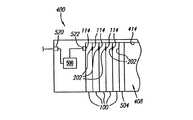
同様に図4ないし図7を参照すると、多数のポータブルメモリ記憶カード100を収容するレシーバ400が示されている。レシーバ400は、複数のポータブルメモリ記憶カード100を収容するようにサイズが決められたキャビティ408を有する。一実施形態では、キャビティ408は、上面410と、上面410に対して実質的に平行な下面412と、上面410と下面412との両方に接続されかつそれらに対して実質的に垂直な後面414と、上面410、下面412および後面414の一端に接続されかつそれらに対して実質的に垂直な第1壁416と、第1壁416に対して実質的に平行であり、上面410、下面412および後面414の他端に接続された第2壁418と、によって画定される。キャビティ408は、ポータブルメモリ記憶カード100を挿入することができるようにサイズが決められている。その場合、カード100の左面126はキャビティ408の下面412と実質的に接触し、カード100の右面128はキャビティ408の上面410と実質的に接触し、カード100の上面122はキャビティ408の後面414と接触する。しかしながら、カード100が容易に滑動(スライド移動)してキャビティ408内に出入りすることができるように、適当な隙間が設けられる。 Similarly, with reference to FIGS. 4-7, a
キャビティ408は、多数のカード100を保持するのに適するように構成される。キャビティ408に挿入される第1のカード100は、その第1面116またはその第2面118が第1壁416に隣接し、その上面122がキャビティ408の後面414に隣接するように、配置される。第1壁416は、多数のレシーバ接点522〜534を有し、それらをまとめてレシーバコネクタと呼んでも良い。一実施形態では、各カード100の接点の数と同じ数のレシーバ接点522〜534が設けられる。更に、レシーバ接点522〜534は、第1面116が第1壁416に隣接するように配置されると各接点102〜114が対応するレシーバ接点522〜534と接触するように、互いに対しおよびカード100に対して配置される。例えば、カード100の第1面116が第1壁416に隣接するように配置されると、カード100の第1接点102が第1レシーバ接点534と接触し、カード100の第2接点104が第2レシーバ接点532と接触し、カード100の第3接点112が第3レシーバ接点524と接触し、カード100の第4接点114が第4レシーバ接点522と接触する。これにより、データが、カードデータ接点102、104、112、114とレシーバデータ接点522、524、532、534とを介して、カード100とレシーバ400との間で伝わる。同様に、カード100の第5接点106が第5レシーバ接点530に接触し、カード100の第6接点110が第6レシーバ接点526と接触する。このため、カード電源用接点106、110とレシーバ電源用接点526、530とを介して、カード100とレシーバ400との間を電流が伝わる。更に、カード100の第7接点108が第7レシーバ接点528と接触する。このため、カード接地接点108とレシーバ接地接点528との間に共通の接地が確立される。 The
代りに、カード100の回転対称性により、第2面118が第1壁416に隣接するように配置されても良い。レシーバ接点522〜534は、第2面118が第1壁416に隣接すると各接点202〜214が対応するレシーバ接点522〜534と接触するように、互いに対しおよびカード100に対して配置される。第2面118の接点202〜214と第1壁416の接点522〜534との間の接続は、第1面116に関して上述したように行われる。 Alternatively, the
一実施形態では、レシーバ接点522〜534は、カード100に関して上述したようなコンタクトパッドである。他の実施形態では、各接点522〜534は、金属板、棒、板ばね、重ね板ばねまたは他の実質的に平坦な導体である。接点522〜534は各々、ばねであるか、またはレシーバ400内のばね(図示せず)に連結されても良い。各接点522〜534は個々のばねに連結されても良く、あるいは、接点522〜534のうちの2つ以上が同じばねに接続されても良い。この実施形態では、各接点522〜534は第1壁416から外側に付勢される。このため、各接点522〜534は、カード100が第1壁416に隣接するように配置された時に、第1壁に向かって戻る方向に撓むことができるように動くことができる。この可撓性により、接点102〜114は、接点202〜214の表面が第2面118と実質的に同一平面になる位置まで撓み得る。望ましい場合は、他のタイプのレシーバ接点522〜534が使用されても良い。レシーバ接点522〜534は、カード100に対する電気的接続を生じさせ保持することができる限り、上述したカード接点102〜114、202〜214のタイプとまったく同じである必要はない。 In one embodiment, receiver contacts 522-534 are contact pads as described above with respect to
キャビティ408内には、リテイナ(保持装置)504が配置される。リテイナ504は、キャビティ408内のいかなるカード100もリテイナ504と第1壁416との間に位置するように配置される。リテイナ504は、第1壁416に向かって付勢され、それによってリテイナ504と第1壁416との間のいかなるカード100もまとめて押圧され、第1壁416に隣接する特定のカード100が第1壁416に対して押圧される。リテイナ504によって加えられる付勢力は、第1壁416に対して実質的に垂直である。リテイナ504は、カード100に対し押圧することができる、あらゆる実質的に剛性の構造であり得る。リテイナ504が第1壁416に向かって付勢されるための機構は定番(標準)的である。例えば、一実施形態では、リテイナ504はばね式である。使用される特定の付勢機構は、本発明には重要ではない。 A retainer (holding device) 504 is disposed in the
キャビティ408内に存在するカード100が1枚であるか複数枚であるかに関らず、第1壁416に隣接するカード100は、リテイナ504の付勢作用によって第1壁416に押圧される。この例では、カード100の第1面116は、第1壁416に向き合うように押圧されてそれと接触するように方向付けられ、カード100は、その上面112がキャビティ408の後面414と接触するように配置される。その結果、カード100の接点102〜114は、第1壁416の接点522〜534と係合し、それによりカード100の接点102〜114と第1壁416の接点522〜534との間に電気的接続が形成される。カード100の接点102〜114は、第1壁416の接点522〜534と同じタイプである必要はない。一実施形態では、カード100の接点102〜114は、第1壁416の接点522〜534と同様にコンタクトパッドである。リテイナ504はカード100を第1壁416に対して押圧することにより、カード100のコンタクトパッド102〜114を第1壁416のコンタクトパッド522〜534に対して押圧し、それらの間の電気的接続を確立する。他の実施形態では、カード100の接点102〜114は比較的平坦な表面を有する導体であり、各接点102〜114が、導体をカード100から外側に付勢するばねに連結される。同様に、第1壁416の接点522〜534は比較的平坦な表面を有する導体であり、各接点522〜534は、導体を第1壁416から外側に付勢するばねに連結される。リテイナ504は、カード100を第1壁426に対して押圧することにより、接点102〜114を対応する接点522〜534と係合させる。カード100の接点102〜114は、カード100が第1壁416にもたれると撓み、第1壁416の接点522〜534に対して押圧される。同様に、第1壁の接点522〜53も同様に撓む。接点102〜114は、カードの本体120と実質的に同一平面である位置で停止する場合があり、接点522〜534は、第1壁416と実質的に同一平面である位置で停止する場合がある。他の実施形態では、カード100の接点102〜114は、比較的平坦な表面を有する導体であり、各接点102〜114は、導体をカード100から外側に付勢するばねに連結される。第1壁416の接点522〜534は、コンタクトパッドである。リテイナ504は、カード100を第1壁416に対して押圧することにより、接点102〜114を対応する接点522〜534に係合させる。カード100の接点102〜114は、カード100が第1壁416に対して取り付けられると、逆向きに撓む。これに従い、カード100の接点102〜114は、第1壁416のコンタクトパッド522〜534に対して押圧される。他の実施形態では、カード100の接点102〜114はコンタクトパッドであり、第1壁416の接点522〜534は、比較的平坦な平面を有する導体であって、各接点522〜534は第1壁416から外側に導体を付勢するばねに連結される。第1壁416の接点522〜534は、カード100が第1壁416に対して取り付けられると逆方向に撓み、カード100のコンタクトパッド102〜114は、第1壁416の接点522〜534に対して押圧される。 The
一実施形態では、複数のポータブルメモリ記憶カード100がキャビティ408内に収容され得る。これらのカード100は、第1壁416とリテイナ504との間のキャビティ408に収容される。リテイナ504は、第1壁416に向かって付勢され、カード100を互いに対して押圧することにより、1つのカード100の面が第1壁416に対して押圧されるようにする。キャビティ408内で共に押圧されるカード100群を、スタックと呼んでも良い。カード100は、各カード100の接点102〜114、202〜214が、スタックの各端部のカード100を除いて隣接する各カード100のコネクタと実質的に位置合せされかつ実質的に係合されるように、キャビティ408内に配置される。すなわち、各カード100は、その上面122がキャビティの後面414と接触するようにキャビティ408内に挿入される。各カード100が回転対称的であり、同じ構成で配置された接点102〜114、202〜214を有するため、隣接するカード100の接点は揃い並ぶ。カード100の第1壁416に隣接する面の接点は、上述したように、第1壁416の接点522〜534と接続する。一実施形態では、リテイナ504は、データおよび/または電源がリテイナ504を伝わることができるように、リテイナ504に隣接するカード100の面の接点に電気的に接続するように適合された接点を有しても良い。他の実施形態では、リテイナ504は、電気的機能ではなく機械的機能を提供し、接点を有してない。他の実施形態では、リテイナ504は、リテイナ504に接触するカード100の面のデータ接点と接触するのに適するように構成された1つまたは複数のバスターミネータ(図示せず)を有しても良い。リテイナ504は、他の電気的コンポーネントを有しても良く、またはスタックの機能を拡張するように適合された他の機能を提供しても良い。 In one embodiment, a plurality of portable
他の実施形態では、各カード100は、第1面116および第2面118に対して平行でありかつ左側面126および右側面128に対して垂直な第2の中心線を中心に、回転対称的である。かかる実施形態では、接点102〜114、202〜214は、実質的に各面116、118の中心に配置され、それによって各カード100を、キャビティ408内に4つの異なる方向のいずれか1つに挿入することができる。 In other embodiments, each
隣接するカード100の接点は、第1壁に隣接するカード100と第1壁416の接点522〜534との間のコネクタの係合に対し上述した方法と実質的に同じ方法で相互に係合する。各カード100は、各カード100の回転対称性と結果としての反転可能性とにより、隣接するカード100に対し2つの方向のうちの1方向に方向付けられ得る。すなわち、各カード100の第1面116は、キャビティ408の第1壁416かまたは第2壁418のいずれの方向に向けられてもよい。
隣接するカード100の面116、118の接点102〜114、202〜214を介してそれらのカード100間の接続のみがなされるため、スタックのカード100は、すべてが同じ厚さである必要はない。このように、異なる厚さを有するカードの使用が容易になる。例として、図7に示すように、第1の厚さを有する多数のカード100が、スタック内において、1つまたは複数のより大きいカード602と1つまたは複数の更に大きいカード600と共に入り混じっている。カード100、600、602の厚さが異なることは、カード100またはレシーバ400の動作に影響を与えない。それは、隣接するカード100の面116、118が、カード100の厚さに関りなく相互接続されるためである。カード100に厚さ制限が課されないため、カード100は、異なるニーズを満たすかまたは異なる記憶テクノロジを利用するために異なる厚さで作成されることが可能となる。更に、隣接するカード100の面116、118が相互接続されるため、任意に多数のカード100を積み重ねることができる。 Since only the connections between the
望ましい場合は、レシーバ400にコントローラ500が含まれても良い。コントローラ500は、後により詳細に説明するように、キャビティ408に積み重ねられるポータブルメモリ記憶カード100に対するおよび/またはそこからのデータの流れを制御するのに適するように構成される。コントローラ500には外部コネクタ520が接続され、それを通して、コントローラ500とスタックとが外部情報ハンドリングシステムまたは他の装置と接続される。外部コネクタ520は、単純な機械的コネクタであっても良く、または遠隔情報ハンドリングシステムにデータを送信しかつそこからデータを受信するのに適するように構成された電子コンポーネントを含んでも良い。すなわち、外部コネクタ520は、モデム、ネットワークインタフェースカードまたは他の通信インタフェースハードウェアを含んでも良い。使用される外部コネクタ520の特定のタイプは、本発明に対して重要ではない。コントローラ500は省略されても良く、その場合、外部コネクタ520は、第1壁416の接点522〜534を介してポータブルメモリ記憶カード100に直接接続されても良い。かかる構成では、データは、外部コネクタ520を通して、レシーバ400のカード100(単数または複数)にコンテンツを記録するかまたはそこからコンテンツを再生するのに適するように構成された外部情報ハンドリングシステムに対しまたはそこから伝送される。レシーバ400は任意に、表示装置、リモートコントロールセンサ、ボリュームコントロール、記録および再生コントロールまたは他のコンポーネント等、ユーザからの入力を受取り、ユーザに対して出力を提供するために使用される、他のコンポーネントを含んでも良い。かかるコンポーネントは標準的である。 If desired, the
同様に図8を参照すると、カード100のスタックを通るデータバス702、電源ループ704および共通接地706のブロック図が示されている。第1壁416とリテイナ504との間でカード100を積み重ねることにより、カード100を経由して、第1壁416のデータ接点522、524、532、534を介してコントローラ500および/または外部コネクタ520まで延在するデータバス702が形成される。カード100は、電気的に互いに接触することによりデータバス702を形成する。キャビティ408の1つの場所(第1壁416)にデータ接点522、524、532、534が設けられることにより、レシーバ400がカード100のスタックによって形成されるデータバス702に接続される。接点522、524、532、534の単一セットを使用してスタックにおよびスタックからデータを伝送することにより、レシーバ400のコストおよび複雑性が最小化される。データは、適切なプロトコルを使用してデータバス702を通過させて送信することができ、利用される特定のバスプロトコルは本発明に対して重要ではない。一実施形態では、各カード100は、2つの隣接するカード100に信号を送信しかつそれらから信号を受信する。そうすることにより、負荷要求が最小化される。カード間の距離が非常に短いため、それらの間でデータを送信するために高クロックレートを使用することができる。高クロックレートにより使用するピンの数を少なくすることを見越したものであり、バス実現性に対応したものである。例として、一実施形態では、データバス702は、高精細テレビ(HDTV)信号の送信および記憶に関連するデータレートをサポートするクロックレートを有する。一実施形態では、電気インタフェースモジュール302はバッファを含み、各カード100を通過する信号は、各カードにおいて電気インタフェースモジュール302を介してバッファリングされる。そこでは、データは先入れ先出し(FIFO)順を使用してカード100間で転送される。このように、バス負荷は低くなりかつ抑制される。望ましい場合は、他のバスプロトコルまたは動作方法が使用されても良い。データバス702を通過して送信されるデータには、アクセスされるメモリアドレスと、そのメモリアドレスに格納されるかまたはそこから検索されたデータと、制御情報と、1つまたは複数のカード100への情報の格納かまたはそこからの情報の検索に関連する他の情報と、が含まれ得る。 Similarly, referring to FIG. 8, a block diagram of a
また、カード100のスタックは、第1壁の電源用接点526、530を通してコントローラ500、外部コネクタ520および/または電源まで延在する、カード100を通る電源ループ704(図8)も形成する。カード100は、電気的に互いに接触することにより、電源ループ704を形成する。キャビティ408の1つの場所(第1壁416)に電源用接点526、530が設けられることにより、レシーバ400がカード100のスタックによって形成される電源ループ704に接続される。一実施形態では、電源ループ704は各カード100の電気インタフェースモジュール302に接続され、それが、関連するメモリ記憶ユニット300に電力を提供する。一実施形態では、電源用接点106、110、206、210は、各カード100において直線状に連なり、それらが各カード100を貫通して直接的なワイヤとして作用することを意味する。このため、スタックのすべてのカード100を通過する電源ループを介して、各カード100に電流が提供される。一実施形態では、リテイナ504は、電源ループ704を完全なものにするために、リテイナ504に隣接するカード100の第2面118の両電源接点206、210に接続するように適応(調整、調節)された導体を含む。その結果、カード100内ではスイッチングが不要となり、それらの構成が簡略化される。他の実施形態では、示されているように、リテイナ504に隣接するカード100が電源ループ704を完全なものとする。すなわち、カード100内の回路(図示せず)が、電流がカード100の第1面116の一方の電源用接点106からカード100の第1面116の他方の電源用接点110まで流れるように、カード100内の導体を切換え、それによって電源ループ704が完成する。 The stack of
また、カード100のスタックは、カード100を通る共通接地706を形成し、それは、キャビティ408の第1壁416の接地接点528を通って延在する。スタックのカード100は、互いに接触することによって共通接地706を形成する。キャビティ408の1つの場所(第1壁416)に接地接点528が提供されることにより、レシーバ400がカード100のスタックによって形成される共通接地706に接続される。一実施形態では、共通接地706は、各カード100内のメモリ記憶ユニット300に接続される。このように、実質的に同じ接地レベルが各カード100に提供され、メモリ記憶ユニット300および電気インタフェースモジュール302と、カード100内に存在する可能性のある他の回路と、による論理演算での使用が可能になる。 The stack of
一実施形態では、キャビティ408は、多数のカード100を保持するようにサイズが決められている。カード100は、格納されている間、レシーバ400に電気的に接続され、各カード100のメモリ記憶ユニット300に記憶されたコンテンツは、レシーバ400を介してユーザがアクセス可能である。すなわち、カード100はすべて、キャビティ408内に積み重ねられている間、データバス702を介してアクセス可能である。このため、レシーバ400は、同時に記憶装置と媒体プレイヤとの両方として機能する。このように、レシーバ400は、例えば個人の音楽コレクションを保持することができると同時に、キャビティ408のカードに記憶された音楽をユーザが再生することができるようにする。レシーバ400は、多数の場所でまたは多数の用途に利用されても良い。レシーバ400は、独立型(スタンドアロン)装置であっても良く、または情報ハンドリングシステム、カーステレオ、ポータブルステレオ、デジタルカメラ、携帯情報端末、無線電話、ラップトップコンピュータまたは他の装置等のような別の装置に組み込まれても良い。レシーバ400が別の装置に組み込まれる場合、コントローラ500および/または外部コネクタ520は、省略されるか、またはレシーバ400のホストである装置の構造に組み込まれても良い。1つの実施の形態として、レシーバ400は、ホームエンタテイメントシステムのコンポーネントとしてオーディオアンプに接続されても良く、それによって、キャビティ408に格納されるカード100内に記憶された音楽を、そのホームエンタテイメントシステムにより再生することができる。他の実施の形態として、レシーバ400は、ホームシアターシステムの一部であっても良く、それにより、キャビティ408に格納されるカード100に記憶された映画または映像を、そのホームシアターシステムにより再生することができる。他の実施の形態として、レシーバ400は、自動車オーディオシステムの一部として自動車のダッシュボードに組み込まれても良く、それによって、キャビティ408に格納されるカード100に記憶された音楽を、その自動車オーディオシステムにより再生することができる。他の実施の形態として、レシーバ400は、パーソナルコンピュータ等の情報ハンドリングシステムに接続されても良く、それによって、キャビティ408に格納されるカード100に記憶されたソフトウェアに、その情報ハンドリングシステムによってアクセスすることができる。他の実施の形態では、情報ハンドリングシステムが、キャビティ408に格納されるカード100の1つまたは複数にデータを書込む。他の実施の形態として、レシーバ400は情報ハンドリングシステムに接続され、それによって、デジタルカメラで取り込まれキャビティ408内に格納されるカードに記憶された写真データを、その情報ハンドリングシステムを使用して見ることができる。他の実施の形態として、レシーバ400は、情報ハンドリングシステムに接続され、キャビティ408に格納されるカードに記憶されたビデオゲームソフトウェアを、その情報ハンドリングシステムを使用して再生することができる。他の実施の形態として、レシーバ400は、単一のカード100を保持するのに適するように構成されても良く、音楽の再生に関連する可動部品を有していない、軽くかつ耐久性のあるポータブルミュージックシステムの一部を形成するように改造されても良い。 In one embodiment, the
図9ないし図11を参照すると、位置合せガイド800を有するカード100が示されている。キャビティ408内に積み重ねられるカード100の位置合せを容易にするために、各カード100に1つまたは複数の位置合せガイド800が設けられても良い。一実施形態では、各位置合せガイド800は、溝802と、反対側の畝804とを含む。一実施形態では、各カード100において、カード100の反対側の側部に、2つの位置合せガイド800が設けられる。例えば、1つの位置合せガイド800は、カードの左側面126に沿って設けられても良く、他の位置合せガイド800は、カードの右側面128に沿って設けられても良い。カード100の左側面126に沿った位置合せガイド800は、カード100の第1面116に隣接する畝804とカード100の第2面118に隣接する溝802とを有する。溝802は、好ましくは、第2面118の方向に開口し、カード100のキャビティ408への挿入方向に沿って延在する。カード100の右側面128に沿った位置合せガイド800は、カード100の第2面118に隣接する畝804とカード100の第1面116に隣接する溝802とを有する。溝802は、好ましくは、第1面116の方向に開口し、カード100のキャビティ408への挿入方向に沿って延在する。このように、カード100は反転可能(リバーシブル)である。すなわち、第1面116および第2面118に対し実質的に平行でありかつ上面122および底面124に対し実質的に垂直である中心線に沿って、その回転対称性を保持する。言換えれば、その中心線は、カード100のキャビティ408への挿入方向に対して実質的に平行であり、それによって、カード100をキャビティ408の2つの方向のいずれにも挿入することができる。位置合せガイド800は、他の実施形態で他の形態をとっても良い。例えば、複数の別個の畝804と対応する溝802とが利用されても良い。他の実施の形態として、畝804の代りに、カード100に1つまたは複数の凸状のディンプル(dimple)が設けられても良く、溝802の代りに、カード100に1つまたは複数の凹状のディボット(divot)が設けられても良い。 Referring to FIGS. 9-11, a
位置合せガイド800は、キャビティ408におけるカード100の互いに対する位置合せを容易にする。2つのカード100が積み重ねられる場合、第1のカードの畝804が第2のカードの対応する溝802に嵌入し、第2のカードの畝804が第1のカードの対応する溝802に嵌入する。畝804は、他のカードの溝802と嵌合するように構成される。このように、溝802と畝804とは、相互にかみ合う。畝804と溝802とがかみ合うことにより、溝802に対して実質的に垂直でありかつカード100の面116、118に対して実質的に平行な方向である、隣接するカード100の動きを低減する。このように、位置合せガイド800は、隣接するカード間の接点102〜114、202〜214の位置合せを助ける。各位置合せガイド800の溝802は、実質的にカード100のキャビティ408への挿入の方向に沿って方向付けられているため、実質的に干渉無しに、カード100をスタックに挿入することができ、またはスタックから取外すことができる。 The
位置合せガイド800の他の実施形態が使用される場合、それらは、1つのカード100の位置合せガイド800が、隣接するカード100の位置合せガイド800に嵌入し、かみ合い、または他の方法で連携して動作してカード100を位置合わせし、カード100を安定させるように、同様に対応する。例えば、位置合せガイド800にディンプルおよびディボットが使用される場合、嵌合する1つのカード100の1つまたは複数のディンプルが隣接するカード100の対応する1つまたは複数のディボットに嵌入するように適合させられる。 When other embodiments of the
他の実施形態では、カード100のスタックに安定性を追加するために、カード100の他の方向に沿って、1つまたは複数の追加の位置合せガイド(図示せず)が設けられても良い。 In other embodiments, one or more additional alignment guides (not shown) may be provided along other directions of the
本発明を特定の実施形態に関して説明したが、本説明は、単に発明の適用の実施の形態であって、限定するものとしてとられるべきではない。従って、開示した実施形態の特徴のあらゆる適応および組合せは、上述した特許請求の範囲とそれらの適法な均等物とによって画定される発明の範囲内にある。本発明には、以下のような実施の態様が含まれる。 Although the present invention has been described with reference to particular embodiments, the description is merely an embodiment of the invention's application and should not be taken as limiting. Accordingly, all adaptations and combinations of the features of the disclosed embodiments are within the scope of the invention as defined by the appended claims and their legal equivalents. The present invention includes the following embodiments.
(実施の態様1)ポータブルメモリカードであって、第1面と、反対側の第2面とを有する本体と、前記本体内のメモリ記憶ユニットと、前記第1面および前記第2面の各々に、前記メモリ記憶ユニットに電気的に接続された少なくとも1つの接点と、を具備するカード。 (Embodiment 1) A portable memory card, a main body having a first surface and a second surface on the opposite side, a memory storage unit in the main body, each of the first surface and the second surface And at least one contact electrically connected to the memory storage unit.
(実施の態様2)前記本体の前記第1面と前記第2面とは、互いに対し実質的に平行である実施の態様1記載のカード。 (Embodiment 2) The card according to Embodiment 1, wherein the first surface and the second surface of the main body are substantially parallel to each other.
(実施の態様3)前記ポータブルメモリカードは回転対称である実施の態様1記載のカード。 (Embodiment 3) The card according to embodiment 1, wherein the portable memory card is rotationally symmetric.
(実施の態様4) 前記本体において画定される少なくとも1つの位置合せガイドを更に具備する実施の態様1記載のカード。 Embodiment 4 The card according to Embodiment 1, further comprising at least one alignment guide defined in the main body.
(実施の態様5)ポータブルメモリカードを格納し、ポータブルメモリカードにアクセスするシステムであって、複数のポータブルメモリカードを収容するように構成され、壁を有するキャビティと、前記壁上の複数の接点と、を備えたレシーバと、第1面と、反対側の第2面とを有する本体と、前記本体内のメモリ記憶ユニットと、前記メモリ記憶ユニットに電気的に接続されたバッファと、前記バッファを介して前記メモリ記憶ユニットに電気的に接続された、前記第1面および前記第2面の各々上の少なくとも1つの接点と、をそれぞれが備えた、前記キャビティ内に積み重ねられる複数のポータブルメモリカードと、を具備し、前記キャビティ内の1つの前記ポータブルメモリカードは、前記キャビティ壁に隣接し、該キャビティ壁上の前記複数の接点に電気的に接続され、前記積み重ねられたポータブルメモリカードは、前記キャビティ壁上の前記接点に接続されたデータバスを形成するシステム。 (Embodiment 5) A system for storing a portable memory card and accessing the portable memory card, the cavity configured to receive a plurality of portable memory cards, having a wall, and a plurality of contacts on the wall A main body having a first surface and an opposite second surface, a memory storage unit in the main body, a buffer electrically connected to the memory storage unit, and the buffer A plurality of portable memories stacked in the cavity, each having at least one contact on each of the first surface and the second surface electrically connected to the memory storage unit via A portable memory card in the cavity adjacent to the cavity wall, the cavity wall Wherein the plurality of contacts are electrically connected, the stacked portable memory card, a system for forming a connected data bus to said contacts on said cavity wall.
(実施の態様6)各ポータブルメモリカードは回転対称であり、それにより、前記キャビティに、少なくとも2つの異なる向きのうちの1つの方向で挿入され得る実施の態様5記載のシステム。 Embodiment 6 The system according to embodiment 5, wherein each portable memory card is rotationally symmetric so that it can be inserted into the cavity in one of at least two different orientations.
(実施の態様7)各ポータブルメモリカードは、前記面の各々に少なくとも1つの位置合せガイドを更に備え、前記スタック内の隣接する前記ポータブルメモリカードは、前記位置合せガイドによって互いに連結する実施の態様5記載のシステム。 Embodiment 7 Each portable memory card further includes at least one alignment guide on each of the surfaces, and adjacent portable memory cards in the stack are connected to each other by the alignment guide. 5. The system according to 5.
(実施の態様8)前記キャビティ内へと延在するリテイナをさらに具備し、前記リテイナは、前記キャビティ壁に対して前記スタックを付勢する実施の態様5記載のシステム。 (Embodiment 8) The system according to embodiment 5, further comprising a retainer extending into the cavity, the retainer biasing the stack against the cavity wall.
(実施の態様9)ポータブルメモリカードをレシーバに格納し、該ポータブルメモリカード内のデータにアクセスする、ポータブルメモリカードの取り扱い方法であり、各ポータブルメモリカードが、2つの対向する面の各々に少なくとも1つの接点を有し、前記レシーバが、複数の接点が配置されるキャビティ壁によって画定されたキャビティを含む方法であって、複数のポータブルメモリカードを前記キャビティ内に積み重ねて、隣接するポータブルメモリカードの前記接点を、該積み重ねられたカードを貫通するデータバスを形成するように互いに接触させるステップと、前記積み重ねられたカードを前記キャビティ壁に対して付勢し、該キャビティ壁に隣接する前記ポータブルメモリカードの前記接点を、該キャビティ壁の前記接点に位置合せしかつ電気的に接続することにより、前記データバスを前記レシーバに接続するステップと、前記データバスを経由させてデータを伝送するステップと、を含む方法。 (Embodiment 9) A portable memory card handling method for storing a portable memory card in a receiver and accessing data in the portable memory card, wherein each portable memory card is at least on each of two opposing surfaces. A method having one contact and wherein the receiver includes a cavity defined by a cavity wall in which a plurality of contacts are disposed, wherein a plurality of portable memory cards are stacked in the cavity, adjacent portable memory cards The contacts of each other to form a data bus that penetrates the stacked cards, and urges the stacked cards against the cavity wall and the portable wall adjacent to the cavity wall. The contact of the memory card is connected to the contact of the cavity wall By connecting aligned using merge electrically, a method comprising the steps of connecting said data bus to said receiver, and transmitting the data by way of the data bus, the.
(実施の態様10)隣接するポータブルメモリカード上の接点は、互いに接触することにより電源ループを形成し、前記電源ループを用いて電流を伝導させるステップを更に含む実施の態様9記載の方法。 (Embodiment 10) The method according to embodiment 9, further comprising the step of contacting the contacts on adjacent portable memory cards with each other to form a power supply loop and conducting current using the power supply loop.
100、600、602:ポータブルメモリ記憶カード
102〜114、202〜214、522〜534:接点
400:レシーバ
408:キャビティ
504:リテイナ
702:データバス
800:位置あわせガイド100, 600, 602: portable memory storage card 102-114, 202-214, 522-534: contact 400: receiver 408: cavity 504: retainer 702: data bus 800: alignment guide
Claims (6)
Translated fromJapanese各ポータブルメモリカードは、第1の面と第2の面とを有する本体と、該本体内のメモリ記憶ユニットと、前記メモリ記憶ユニットに電気的に接続された、前記第1の面および前記第2の面の各々上の少なくとも1つの接点とを備え、
前記レシーバは、
壁を有し、複数の前記ポータブルメモリカードを格納することができるキャビティと、
前記壁上の少なくとも1つの接点であって、前記ポータブルメモリカードが前記壁に隣接したときに、前記キャビティの前記壁上で位置決めされて前記ポータブルメモリカードの前記少なくとも1つの接点と位置合わせされて接続される前記壁上の少なくとも1つの接点と、
前記キャビティ内に伸張して少なくとも1つの前記ポータブルメモリカードを前記キャビティの前記壁にバイアスし、バイアスされた該ポータブルメモリカードからデータや電源が伝わるようにするようにするための接点とコンポーネントを有するリテイナと、
を備えることを特徴とする、レシーバ。A receiver for storing and accessing a portable memory card,
Each portable memory card includes a main body having a first surface and a second surface, a memory storage unit in the main body, and the first surface and the first surface electrically connected to the memory storage unit. At least one contact on each of the two surfaces,
The receiver is
A cavity having a wall and capable of storing a plurality of said portable memory cards;
At least one contact on the wall, wherein the portable memory card is positioned on the wall of the cavity and aligned with the at least one contact of the portable memory card when the portable memory card is adjacent to the wall. At least one contact on the wall to be connected;
Contacts and components for extending into the cavity to bias the at least one portable memory card against the wall of the cavity so that data and power can be transmitted from the biased portable memory card With the retainer,
A receiver comprising:
前記ポータブルメモリカードは相互に対向する第1、第2の面と該第1、第2の面上の接点とを有し、前記ポータブルメモリカードと前記接点とは、前記ポータブルメモリカードが前記コンテンツ記憶装置に挿入されて前記第1、第2の面を合わせて積み重ねられると、挿入された前記ポータブルメモリカードの前記接点が接触してバスを形成するように構成されており、
前記コンテンツ記憶装置は、
1つの方向に伸張する内部キャビティであって、前記1つの方向に沿って少なくとも1つの前記ポータブルメモリカードを積み重ねられるようにした該内部キャビティを画定する複数の壁を備えたレシーバと、
前記1つの方向に沿って前記内部キャビティ内で位置決めされ、前記ポータブルメモリカードの1つをバイアスして前記少なくとも1つの積み重ねられたポータブルメモリカードを前記1つの方向に沿ってかつ該1つの方向に垂直に前記レシーバの壁に規制して、前記少なくとも1つの積み重ねられたポータブルメモリカードの前記接点が電気的に接続されるようにするとともに、前記バイアスされたポータブルメモリカードからデータや電源が伝わるようにするようにするための接点とコンポーネントを有するリテイナと、
前記レシーバに結合され前記バスを接続する少なくとも1つの接点と、
を有することを特徴とする、コンテンツ記憶装置。A content storage device capable of storing a plurality of portable memory cards and accessing the portable memory card,
The portable memory card has first and second surfaces facing each other and contacts on the first and second surfaces, and the portable memory card and the contacts are connected to each other by the portable memory card. When inserted into a storage device and stacked with the first and second surfaces aligned, the contacts of the inserted portable memory card come into contact to form a bus,
The content storage device includes:
A receiver comprising an inner cavity extending in one direction, wherein the walls define at least one portable memory card to be stacked along the one direction and defining the inner cavity;
Positioned within the internal cavity along the one direction and biasing one of the portable memory cards to move the at least one stacked portable memory card along the one direction and into the one direction. Vertically regulating the receiver wall to electrically connect the contacts of the at least one stacked portable memory card and to transmit data and power from the biased portable memory card A retainer having contacts and components to ensure that
At least one contact coupled to the receiver and connecting the bus;
A content storage device comprising:
Applications Claiming Priority (1)
| Application Number | Priority Date | Filing Date | Title |
|---|---|---|---|
| US09/853,729US6618258B2 (en) | 2001-05-10 | 2001-05-10 | Portable memory card system |
Related Parent Applications (1)
| Application Number | Title | Priority Date | Filing Date |
|---|---|---|---|
| JP2002132643ADivisionJP2002352214A (en) | 2001-05-10 | 2002-05-08 | Portable memory card, portable memory card system and method for handling portable memory card |
Publications (1)
| Publication Number | Publication Date |
|---|---|
| JP2007280414Atrue JP2007280414A (en) | 2007-10-25 |
Family
ID=25316750
Family Applications (2)
| Application Number | Title | Priority Date | Filing Date |
|---|---|---|---|
| JP2002132643APendingJP2002352214A (en) | 2001-05-10 | 2002-05-08 | Portable memory card, portable memory card system and method for handling portable memory card |
| JP2007143397APendingJP2007280414A (en) | 2001-05-10 | 2007-05-30 | Receiver and content storage device |
Family Applications Before (1)
| Application Number | Title | Priority Date | Filing Date |
|---|---|---|---|
| JP2002132643APendingJP2002352214A (en) | 2001-05-10 | 2002-05-08 | Portable memory card, portable memory card system and method for handling portable memory card |
Country Status (2)
| Country | Link |
|---|---|
| US (1) | US6618258B2 (en) |
| JP (2) | JP2002352214A (en) |
Families Citing this family (24)
| Publication number | Priority date | Publication date | Assignee | Title |
|---|---|---|---|---|
| US7065557B2 (en)* | 2001-04-12 | 2006-06-20 | Hewlett-Packard Development Company, L.P. | Method and apparatus for consuming content at a network address |
| US20040254940A1 (en)* | 2003-01-31 | 2004-12-16 | Brush Hector Cesar | Digital media distribution method and system |
| EP1649410A2 (en)* | 2003-07-17 | 2006-04-26 | SanDisk Corporation | Memory card with raised portion |
| US20050013106A1 (en)* | 2003-07-17 | 2005-01-20 | Takiar Hem P. | Peripheral card with hidden test pins |
| US7416132B2 (en)* | 2003-07-17 | 2008-08-26 | Sandisk Corporation | Memory card with and without enclosure |
| US7386765B2 (en)* | 2003-09-29 | 2008-06-10 | Intel Corporation | Memory device having error checking and correction |
| US20050155787A1 (en)* | 2004-01-20 | 2005-07-21 | Pierre Liu | Transparent small memory card |
| CA2570715A1 (en)* | 2004-06-17 | 2005-12-29 | Walletex Microelectronics Ltd. | Improved connector and device for flexibly connectable computer systems |
| US7495926B2 (en)* | 2004-10-05 | 2009-02-24 | Sony Ericsson Mobile Communications Ab | Interface module for electronic devices |
| KR100674926B1 (en)* | 2004-12-08 | 2007-01-26 | 삼성전자주식회사 | Memory card and its manufacturing method |
| KR100843274B1 (en)* | 2007-01-02 | 2008-07-03 | 삼성전자주식회사 | Memory card having double-sided contact pad and method for manufacturing same |
| EP2410469A1 (en)* | 2010-07-19 | 2012-01-25 | SmarDTV S.A. | Adaptor for connection of a host device to a digital communication network |
| TWI415232B (en)* | 2010-11-15 | 2013-11-11 | Walton Advanced Eng Inc | Screen type storage device |
| US8649820B2 (en) | 2011-11-07 | 2014-02-11 | Blackberry Limited | Universal integrated circuit card apparatus and related methods |
| US8936199B2 (en) | 2012-04-13 | 2015-01-20 | Blackberry Limited | UICC apparatus and related methods |
| USD703208S1 (en) | 2012-04-13 | 2014-04-22 | Blackberry Limited | UICC apparatus |
| USD701864S1 (en) | 2012-04-23 | 2014-04-01 | Blackberry Limited | UICC apparatus |
| CN103870870A (en)* | 2012-12-13 | 2014-06-18 | 鸿富锦精密工业(深圳)有限公司 | Data storage card |
| USD759022S1 (en)* | 2013-03-13 | 2016-06-14 | Nagrastar Llc | Smart card interface |
| USD758372S1 (en) | 2013-03-13 | 2016-06-07 | Nagrastar Llc | Smart card interface |
| USD729808S1 (en)* | 2013-03-13 | 2015-05-19 | Nagrastar Llc | Smart card interface |
| USD780763S1 (en)* | 2015-03-20 | 2017-03-07 | Nagrastar Llc | Smart card interface |
| USD864968S1 (en) | 2015-04-30 | 2019-10-29 | Echostar Technologies L.L.C. | Smart card interface |
| US12102583B2 (en)* | 2021-05-17 | 2024-10-01 | MerchSource, LLC | Temperature-controlled massage node light indicator |
Citations (1)
| Publication number | Priority date | Publication date | Assignee | Title |
|---|---|---|---|---|
| JP2000306070A (en)* | 1999-04-19 | 2000-11-02 | Sony Corp | Card type information recording medium and recording and reproducing device therefor |
Family Cites Families (4)
| Publication number | Priority date | Publication date | Assignee | Title |
|---|---|---|---|---|
| JPH02111861U (en)* | 1989-02-27 | 1990-09-06 | ||
| US5664228A (en)* | 1995-08-09 | 1997-09-02 | Microsoft Corporation | Portable information device and system and method for downloading executable instructions from a computer to the portable information device |
| US5883377A (en)* | 1995-11-20 | 1999-03-16 | International Card Technologies, Inc. | Multiple magnetic stripe transaction cards and systems for the utilization thereof |
| US6276608B1 (en)* | 1998-12-29 | 2001-08-21 | Daimlerchrysler Ag | Data storage and communication system |
- 2001
- 2001-05-10USUS09/853,729patent/US6618258B2/ennot_activeExpired - Fee Related
- 2002
- 2002-05-08JPJP2002132643Apatent/JP2002352214A/enactivePending
- 2007
- 2007-05-30JPJP2007143397Apatent/JP2007280414A/enactivePending
Patent Citations (1)
| Publication number | Priority date | Publication date | Assignee | Title |
|---|---|---|---|---|
| JP2000306070A (en)* | 1999-04-19 | 2000-11-02 | Sony Corp | Card type information recording medium and recording and reproducing device therefor |
Also Published As
| Publication number | Publication date |
|---|---|
| US6618258B2 (en) | 2003-09-09 |
| US20020167791A1 (en) | 2002-11-14 |
| JP2002352214A (en) | 2002-12-06 |
Similar Documents
| Publication | Publication Date | Title |
|---|---|---|
| JP2007280414A (en) | Receiver and content storage device | |
| US20050079738A1 (en) | USB storage device including USB plug with top and bottom terminals | |
| KR100839034B1 (en) | How to record and play back portable storage devices and video signals | |
| US7443690B2 (en) | Adapter device, memory device and integrated circuit chip | |
| JP3886561B2 (en) | Memory chip architecture | |
| US20030221066A1 (en) | Memory card and memory card data recording method | |
| US20040252560A1 (en) | Multifunctional flash memory drive | |
| TWI224775B (en) | Portable data storage drive cartridge with external interface at each end | |
| US20060075342A1 (en) | Handheld pda video accessory | |
| US6695637B1 (en) | Tray-style memory card connector | |
| US6728108B2 (en) | Access device of memory card | |
| US8146166B2 (en) | System and method for providing content in two formats on one DRM disk | |
| EP0744751A2 (en) | Smart tray for audio player | |
| US7900009B2 (en) | Prerecorded digital portable personal stereo | |
| CN100381979C (en) | Multi-interface memory card and conversion module thereof | |
| US20020167470A1 (en) | Mouse with data-transmission function | |
| US20070058923A1 (en) | Use of flash based memory to store and play feature length licensed movie or TV productions | |
| JP2003196606A (en) | Loading mechanism of recording medium and recording medium drive device | |
| US20050152231A1 (en) | Conversion device of MP3 | |
| US7346916B2 (en) | Disk cartridge and device to which disk cartridge is inserted | |
| TW200842690A (en) | Memory card, imaging apparatus, and recording/reproducing apparatus | |
| US20060187194A1 (en) | Multimedia player having a detachable display screen | |
| CN2498709Y (en) | Digital video playback device | |
| JP3383167B2 (en) | Card type optical disk cartridge and drive device thereof | |
| KR200309594Y1 (en) | Combination system with the common memory |
Legal Events
| Date | Code | Title | Description |
|---|---|---|---|
| A977 | Report on retrieval | Free format text:JAPANESE INTERMEDIATE CODE: A971007 Effective date:20100201 | |
| A131 | Notification of reasons for refusal | Free format text:JAPANESE INTERMEDIATE CODE: A131 Effective date:20100209 | |
| A521 | Written amendment | Free format text:JAPANESE INTERMEDIATE CODE: A523 Effective date:20100423 | |
| A131 | Notification of reasons for refusal | Free format text:JAPANESE INTERMEDIATE CODE: A131 Effective date:20100727 | |
| A02 | Decision of refusal | Free format text:JAPANESE INTERMEDIATE CODE: A02 Effective date:20110104 |