JP2007279577A - Electronic equipment - Google Patents
Electronic equipmentDownload PDFInfo
- Publication number
- JP2007279577A JP2007279577AJP2006108660AJP2006108660AJP2007279577AJP 2007279577 AJP2007279577 AJP 2007279577AJP 2006108660 AJP2006108660 AJP 2006108660AJP 2006108660 AJP2006108660 AJP 2006108660AJP 2007279577 AJP2007279577 AJP 2007279577A
- Authority
- JP
- Japan
- Prior art keywords
- base chassis
- stand
- outer peripheral
- electronic device
- attached
- Prior art date
- Legal status (The legal status is an assumption and is not a legal conclusion. Google has not performed a legal analysis and makes no representation as to the accuracy of the status listed.)
- Pending
Links
Images


Classifications
- G—PHYSICS
- G06—COMPUTING OR CALCULATING; COUNTING
- G06F—ELECTRIC DIGITAL DATA PROCESSING
- G06F1/00—Details not covered by groups G06F3/00 - G06F13/00 and G06F21/00
- G06F1/16—Constructional details or arrangements
- G—PHYSICS
- G06—COMPUTING OR CALCULATING; COUNTING
- G06F—ELECTRIC DIGITAL DATA PROCESSING
- G06F1/00—Details not covered by groups G06F3/00 - G06F13/00 and G06F21/00
- G06F1/16—Constructional details or arrangements
- G06F1/1601—Constructional details related to the housing of computer displays, e.g. of CRT monitors, of flat displays
- G06F1/1605—Multimedia displays, e.g. with integrated or attached speakers, cameras, microphones
- G—PHYSICS
- G06—COMPUTING OR CALCULATING; COUNTING
- G06F—ELECTRIC DIGITAL DATA PROCESSING
- G06F2200/00—Indexing scheme relating to G06F1/04 - G06F1/32
- G06F2200/16—Indexing scheme relating to G06F1/16 - G06F1/18
- G06F2200/163—Indexing scheme relating to constructional details of the computer
- G06F2200/1631—Panel PC, e.g. single housing hosting PC and display panel
Landscapes
- Engineering & Computer Science (AREA)
- Theoretical Computer Science (AREA)
- General Engineering & Computer Science (AREA)
- Human Computer Interaction (AREA)
- Physics & Mathematics (AREA)
- General Physics & Mathematics (AREA)
- Computer Hardware Design (AREA)
- Multimedia (AREA)
- Devices For Indicating Variable Information By Combining Individual Elements (AREA)
- Microelectronics & Electronic Packaging (AREA)
- Casings For Electric Apparatus (AREA)
Abstract
Description
Translated fromJapanese本発明は電子機器についての技術分野に関する。詳しくは、透明材料によって各部が一体に形成されたベースシャーシの両面に所要の各部を取り付けて構成の簡素化及び良好な組立性の確保を図る技術分野に関する。 The present invention relates to the technical field of electronic equipment. More specifically, the present invention relates to a technical field in which required parts are attached to both surfaces of a base chassis in which the parts are integrally formed of a transparent material, thereby simplifying the configuration and ensuring good assembly.
電子機器、例えば、パーソナルコンピューター、PDA(Personal Digital Assistant)、テレビ等は、画像を表示するための表示パネルを有している。 Electronic devices such as personal computers, PDAs (Personal Digital Assistants), and televisions have a display panel for displaying images.
このような電子機器にあっては、表示パネルの前面側にパネル部が設けられ、該パネル部が透明材料によって形成されているものがある(例えば、特許文献1参照)。 In such an electronic device, there is one in which a panel portion is provided on the front side of the display panel, and the panel portion is formed of a transparent material (for example, see Patent Document 1).
特許文献1に記載された電子機器にあっては、矩形の枠状に形成されたブラケットの内側に表示パネルを有する表示ユニットが配置され、ブラケットの前面に表示ユニットを前方から覆う透明な前面パネルが取り付けられている。前面パネルの外形は表示パネルの外形より大きくされ、表示パネルの外周側に前面パネルの外周部が位置されている。 In the electronic device described in
ところが、上記した従来の電子機器にあっては、透明材料によって形成された前面パネルが表示ユニットを前方から覆う飾り板として機能するのみであるため、前面パネルと各部を取り付けるためのブラケットとが各別に存在し、構成が複雑であると共に部品点数も多く組立工数が多いと言う問題がある。 However, in the above-described conventional electronic device, the front panel formed of a transparent material only functions as a decorative plate that covers the display unit from the front. There exists a problem that it exists separately, the configuration is complicated, the number of parts is large, and the number of assembly steps is large.
そこで、本発明電子機器は、上記した問題点を克服し、構成の簡素化及び良好な組立性の確保を図ることを課題とする。 Therefore, an object of the electronic device of the present invention is to overcome the above-described problems and to simplify the configuration and ensure good assemblability.
本発明電子機器は、上記した課題を解決するために、透明材料によって各部が一体に形成されると共に互いに反対側に位置する両面がそれぞれ第1の取付面部及び第2の取付面部として形成されたベースシャーシを設け、該ベースシャーシの第1の取付面部に表示パネルを有する表示ユニットを取り付け、ベースシャーシの第2の取付面部に少なくとも制御回路基板と該制御回路基板を覆うリアカバーとを取り付けたものである。 In order to solve the above-described problems, the electronic device according to the present invention is formed by integrally forming each part with a transparent material, and both surfaces positioned on opposite sides are formed as a first mounting surface part and a second mounting surface part, respectively. A base chassis is provided, a display unit having a display panel is attached to a first attachment surface portion of the base chassis, and at least a control circuit board and a rear cover that covers the control circuit board are attached to a second attachment surface portion of the base chassis. It is.
従って、本発明電子機器にあっては、ベースシャーシが飾り板として機能すると共に各部が取り付けられるブラケットとしても機能する。 Therefore, in the electronic device of the present invention, the base chassis functions as a decorative plate and also functions as a bracket to which each part is attached.
本発明電子機器は、透明材料によって各部が一体に形成されると共に互いに反対側に位置する両面がそれぞれ第1の取付面部及び第2の取付面部として形成されたベースシャーシを備え、該ベースシャーシの第1の取付面部に表示パネルを有する表示ユニットを取り付け、ベースシャーシの第2の取付面部に少なくとも制御回路基板と該制御回路基板を覆うリアカバーとを取り付けたことを特徴とする。 The electronic apparatus of the present invention includes a base chassis in which the respective parts are integrally formed of a transparent material and both surfaces located on opposite sides are formed as a first mounting surface part and a second mounting surface part, respectively. A display unit having a display panel is attached to the first attachment surface, and at least a control circuit board and a rear cover that covers the control circuit board are attached to the second attachment surface of the base chassis.
従って、構成が簡素であると共に部品点数も少なく組立工数の低減を図ることができる。 Therefore, the structure is simple and the number of parts is small, so that the number of assembling steps can be reduced.
請求項2に記載した発明にあっては、ベースシャーシの第1の取付面部における外周部を除いた部分に取付用凹部を形成し、ベースシャーシを、上記外周部と、該外周部の内側に位置し外周部と平行な底面部と、外周部の内周縁と底面部の外周縁に連続し外周部及び底面部に対して折り曲げられた連結部とによって構成し、上記表示パネルを取付用凹部に挿入して配置しベースシャーシに取り付けるようにしたので、ベースシャーシの強度を上げることができる。 In the invention described in
請求項3に記載した発明にあっては、ベースシャーシの底面部の厚みを外周部の厚みより薄く形成したので、ベースシャーシの高い強度を確保した上で薄型化を図ることができる。 In the invention described in
請求項4に記載した発明にあっては、上記リアカバーの背面に回動自在に支持されたスタンドを設け、該スタンドとベースシャーシによって支えて載置面に載置するようにしたので、ベースシャーシの他に専用の支えを設ける必要がなく、部品点数の削減及び構造の簡素化を図ることができる。 In the invention described in
請求項5に記載した発明にあっては、ベースシャーシの下端部に保持部材を取り付け、該保持部材に、弾性を有し載置面に接する載置用パッドを取り付けたので、電子機器の載置面に対する載置状態の安定化を図ることができる。 In the invention described in
以下に、本発明を実施するための最良の形態を添付図面に従って説明する。以下に示す最良の形態は、本発明電子機器をパーソナルコンピューターに適用したものである。 The best mode for carrying out the present invention will be described below with reference to the accompanying drawings. In the following best mode, the electronic device of the present invention is applied to a personal computer.
尚、本発明電子機器の適用範囲はパーソナルコンピューターに限られることはなく、本発明電子機器は、例えば、PDA(Personal Digital Assistant)、ネットワーク端末、携帯情報端末、ワークステーション等の各種の情報処理装置や音響機器、家庭用家電製品等の各種の電子機器に広く適用することができる。 Note that the application range of the electronic device of the present invention is not limited to a personal computer, and the electronic device of the present invention is, for example, various information processing apparatuses such as a PDA (Personal Digital Assistant), a network terminal, a portable information terminal, and a workstation. It can be widely applied to various electronic devices such as audio equipment, household appliances and the like.
以下の説明にあっては、説明の便宜上、使用者がパーソナルコンピューターの表示画面を視認する方向を上下前後左右の各方向とし、手前側(使用者側)を前方、使用者の左手方向及び右手方向をそれぞれ左方及び右方とする。 In the following explanation, for convenience of explanation, the direction in which the user visually recognizes the display screen of the personal computer is defined as the up / down / front / back / left / right directions, the front side (user side) is the front, the user's left hand direction and the right hand The directions are left and right, respectively.
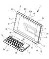
電子機器(パーソナルコンピューター)1は装置本体2とキーボード3と装置本体2の背面2aに回動自在に支持されたスタンド4とを備えている(図1参照)。 An electronic apparatus (personal computer) 1 includes an apparatus
キーボード3は、例えば、装置本体2から分離されており、キーボード3には所定の操作キー3a、3a、・・・が設けられている。キーボード3の操作キー3a、3a、・・・を操作すると、操作した操作キー3aに応じた信号が出力され、この出力された信号が装置本体2に設けられた図示しない受信部に無線で入力されて操作キー3aの操作に応じた各種の処理が実行される。 The
このように電子機器1にあっては、キーボード3が装置本体2から分離されているため、無線信号が装置本体2で受信可能な範囲内において、必要に応じてキーボード3を任意の位置で使用することが可能である。 As described above, in the
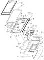
尚、電子機器は上記したキーボード3が装置本体2から分離したタイプに限られることはなく、例えば、図2に示すように、装置本体2と該装置本体2の前面2bに折畳自在に支持されたキーボード3と装置本体2の背面2aに回動自在に支持されたスタンド4とを備えた電子機器1Aであってもよい。電子機器1Aにあっては、不使用時にキーボード3を折り畳んでおくことが可能であるため、キーボード3の不使用時における配置スペースが小さくなるという利点を有する。 The electronic device is not limited to the type in which the
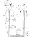
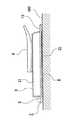
装置本体2は、図3及び図4に示すように、ベースシャーシ5の前後両面に所要の各部が取り付けられて構成され、ベースシャーシ5と該ベースシャーシ5の前面に取り付けられた表示ユニット6とベースシャーシ5の後面に取り付けられた制御回路基板7及びリアカバー8とを有している。 As shown in FIGS. 3 and 4, the apparatus
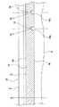
ベースシャーシ5は、例えば、アクリル樹脂等の透明材料を用いた射出成形によって前後方向を向く板状に形成されている。ベースシャーシ5は前面が第1の取付面部5aとされ、後面が第2の取付面部5bとされている。 The
ベースシャーシ5には前方に開口された取付用凹部9が形成されている。取付用凹部9はベースシャーシ5の外周部10を除いた部分に形成され、図3及び図5に示すように、外周部10に平行な底面部11と、外周部10の内周縁と底面部11の外周縁を連結し外周部10及び底面部11に対して略直交する連結部12とに囲まれた空間として形成されている。 The
このように外周部10と底面部11を両者に対して屈曲する連結部12によって連結してベースシャーシ5を形成することにより、ベースシャーシ5の強度を上げることができる。 In this way, the
ベースシャーシ5は、図5に示すように、外周部10の厚みT1が底面部12の厚みT2より厚くされ、例えば、外周部10の厚みT1が5mmとされ、底面部12の厚みT2が2.4mmとされている。 As shown in FIG. 5, the
このように外周部10の厚みT1を底面部12の厚みT2より厚くすることにより、ベースシャーシ5の高い強度を確保した上で薄型化を図ることができる。 Thus, by making the thickness T1 of the outer
ベースシャーシ5の外周部10には、左右方向における中央部に上方に開口された配置用切欠10aが形成されている(図6参照)。 The outer
ベースシャーシ5の外周部10の下端部には、その左右両端部を除いた部分に下方に開口された浅い取付用切欠10bが形成されている。取付用切欠10bの左端寄りの位置及び右端寄りの位置には、それぞれ下方に開口された三つずつの保持凹部10c、10c、10cが左右に離隔して形成されている。 At the lower end of the outer
ベースシャーシ5の外周部10には、右端部における上端部に蓄光ランプ部13が形成されている。蓄光ランプ部13は、例えば、電源の投入状態を示すランプ部であり、電源が投入されている状態において点灯し、電源が投入されていない状態において消灯する。 On the outer
蓄光ランプ部13はベースシャーシ5に後方に開口された溝形状を形成することにより形成されている(図7参照)。蓄光ランプ部13は、図6及び図7に示すように、上方に開口された円弧状を為す円弧状部14と該円弧状部14の先端間に位置する上下に延びる直線部15とからなる。 The
円弧状部14の奥面部14aは上方へ行くに従って前方へ変位するように傾斜され、円弧状部14の溝の深さは上方へ行くに従って深くなるように形成されている(図7及び図8参照)。 The
直線部15の奥面部15aは、図7に示すように、上方へ行くに従って前方へ変位するように傾斜され、直線部15の溝の深さは上方へ行くに従って深くなるように形成されている。直線部15の下端の溝の深さは、円弧状部14における直線部15の真下に位置する部分の上端の溝の深さと同じに形成されている。 As shown in FIG. 7, the
円弧状部14及び直線部15の各奥面部14a、15aには、微細な凹凸形状、例えば、シボ加工等が施されている。 Each of the
蓄光ランプ部13の下方には第1の素子搭載用基板16が配置されている(図7及び図9参照)。第1の素子搭載用基板16は上下方向を向き、一部がベースシャーシ5に形成された上側素子配置孔10d(図6参照)に挿入された状態で配置されている。上側素子配置孔10dは蓄光ランプ部13の直ぐ下側に形成されている。 A first
第1の素子搭載用基板16の上面には、例えば、三つの第1の半導体発光素子17、17、17が左右に離隔して搭載され(図9参照)、該第1の半導体発光素子17、17、17は蓄光ランプ部16の真下に位置されている。第1の半導体発光素子17、17、17は、例えば、中央のものが橙色の光を発光する素子であり、左右のものが緑色の光を発光する素子である。 On the upper surface of the first
蓄光ランプ部13には、奥面部14a、15aに第1の半導体発光素子17、17、17から発光された光P1(図7参照)が入射されるが、上記したように、奥面部14a、15aを傾斜させ、円弧状部14及び直線部15の溝の深さを上方へ行くに従って深くなるように形成し、直線部15の下端の溝の深さを円弧状部14における直線部15の真下に位置する部分の上端の溝の深さと同じに形成することにより、光P1が奥面部14a、15aに満遍なく入射され、光の入射光率の向上を図ることができる。 Light P1 (see FIG. 7) emitted from the first semiconductor
蓄光ランプ部13に光P1が入射されると、光P1は奥面部14a、15aに形成された微細な凹凸形状によって乱反射され、光P1が蓄光ランプ部13からベースシャーシ5の内部を透過して前方側へ出射される。 When the light P1 is incident on the
電子機器1においては、例えば、通常の動作モードにおいて左右に位置する第1の半導体発光素子17、17から光P1が発光され、休止モードにおいて中央に位置する第1の半導体発光素子17から光P1が発光される。 In the
上記のように、電子機器1にあっては、ベースシャーシ5に蓄光ランプ部13を設け、半導体発光素子17、17、17から発光された光P1を蓄光ランプ部13によって出射するようにしているため、ベースシャーシ5に蓄光ランプ部13を形成すると言う簡素な構造を確保した上で、視認性の向上を図ることができる。 As described above, in the
ベースシャーシ5の外周部10には、右端部における下端部に反射ランプ部18、18が形成されている(図6参照)。反射ランプ部18、18は、例えば、それぞれワイヤレスLAN(Local Area Network)の接続状態やハードディスクドライブのアクセス状態等を示すランプ部であり、ワイヤレスLANの接続又はハードディスクドライブのアクセスが行われている状態において点灯又は点滅し、これらの接続又はアクセスが行われていない状態において消灯する。 In the outer
反射ランプ部18、18はベースシャーシ5に後方に開口された溝形状を形成することにより形成されている(図10参照)。 The
反射ランプ部18、18の奥面部18a、18aは下方へ行くに従って前方へ変位するように傾斜されている(図10参照)。また、反射ランプ部18、18の奥面部18a、18aは右方へ行くに従って前方へ変位するようにも傾斜されている(図11参照)。 The
反射ランプ部18、18の奥面部18a、18aは、鏡面に形成されている。 反射ランプ部18、18の上方には前後方向を向く第2の素子搭載用基板19が配置されている(図9及び図10参照)。 The
第2の素子搭載用基板19の前面には、例えば、二つの第2の半導体発光素子20、20が左右に離隔して搭載され、該第2の半導体発光素子20、20はベースシャーシ5に形成された下側素子配置孔10e(図6参照)に配置され、それぞれ反射ランプ部18、18の真上に位置されている(図10参照)。下側素子配置孔10eは反射ランプ部18、18の直ぐ上側に形成されている。 On the front surface of the second
反射ランプ部18、18には、奥面部18a、18aに第2の半導体発光素子20、20から発光された光P2(図10参照)が入射される。 The light P2 (see FIG. 10) emitted from the second semiconductor
反射ランプ部18、18に光P2が入射されると、光P2は奥面部18a、18aで内面反射され、反射ランプ部18、18からベースシャーシ5の内部を透過して前方側へ出射される。 When the light P2 is incident on the
このとき、上記したように、反射ランプ部18、18の奥面部18a、18aが右方へ行くに従って前方へ変位するように傾斜されているため、光P2は電子機器1の中央側、即ち、表示ユニット6の中央を横切る法線H(図11参照)に寄る方向へ向けて反射される。 At this time, as described above, since the
従って、反射ランプ部18、18で反射された光P2が電子機器1の使用者に視認し易く、ベースシャーシ5に溝形状を形成することにより反射ランプ部18、18を形成すると言う簡素な構造を確保した上で、視認性の向上を図ることができる。 Therefore, the light P2 reflected by the
ベースシャーシ5の底面部11には、それぞれ所定の位置に、スピーカー配置孔11a、11a、接続線通し孔11b及び冷却空気流通孔11c、11c、・・・等が形成されている。また、底面部11及び連結部12の各位置には、ネジ止め用の取付ボスや位置決め突部、位置決め孔、取付用突起、取付孔等の各部も形成されている。 Speaker placement holes 11a and 11a, connection line through
表示ユニット6は、表示パネル21とフロントパネル22を有している(図1乃至図4参照)。 The
表示パネル21は、例えば、液晶パネルであり、外形がベースシャーシ5の底面部11の外形より一回り小さくされている。 The
フロントパネル22は矩形の枠状に形成され、外形がベースシャーシ5の底面部11の外形より一回り大きくされている。 The
表示パネル21はベースシャーシ5の取付用凹部9に挿入されて配置され、ネジ止め等の適宜の手段によってベースシャーシ5の底面部11に取り付けられる。表示パネル21がベースシャーシ5に取り付けられた状態において、フロントパネル22が外周部10の内周縁を前方から覆った状態でネジ止め等の適宜の手段によってベースシャーシ5に取り付けられる。表示パネル21は、その外周縁がフロントパネル22によって前方から押さえられる。 The
表示パネル21の駆動時には、該表示パネル21の駆動に伴う熱が生じるが、発生した熱はベースシャーシ5に形成された冷却空気流通孔11c、11c、・・・を介してベースシャーシ5の背面側に流通され、リアカバー8に形成された図示しない放熱孔から外部へ放出される。従って、表示パネル21の温度上昇が抑制される。 When the
制御回路基板7は、電子機器1の全体の制御処理を行う基板である。制御回路基板7は、基板23と該基板23上に搭載されたCPU(中央演算処理装置)やチップセット等の所定の電子部品23a、23a、・・・とを有している(図3及び図4参照)。 The
制御回路基板7は、ベースシャーシ5の背面である第2の取付面部5bの所定の位置にネジ止め等の適宜の手段によって取り付けられる。制御回路基板7が第2の取付面部5bに取り付けられた状態において、図示しない接続線がベースシャーシ5に形成された接続線通し孔11bを挿通され、接続線によって表示パネル21と制御回路基板7のパネル駆動回路とが接続される。 The
ベースシャーシ5の第2の取付面部5bには、ディスクドライブやカードスロット等のメディア駆動部24及び冷却用ファン25等の所定の部品がネジ止め等の適宜の手段によって取り付けられる。 Predetermined parts such as a
ベースシャーシ5に形成されたスピーカー配置孔11a、11aにはそれぞれスピーカー26、26が挿入されて配置され、ベースシャーシ5にネジ止め等の適宜の手段によって取り付けられる。
スピーカー配置孔11a、11aにスピーカー26、26を挿入して取り付けることにより、ベースシャーシ5の第1の取付面部5a上にスピーカー26、26を取り付ける場合に比し、スピーカー26、26の前方への突出量が小さく、電子機器1の薄型化を図ることができる。 By inserting the
上記のように、ベースシャーシ5の第2の取付面部5bに制御回路基板7、メディア駆動部24、冷却用ファン25等の所定の部品及びスピーカー26、26等の所要の各部が取り付けられた状態において、これらの各部を後方から覆うようにリアカバー8が第2の取付面部5bにネジ止め等の適宜の手段によって取り付けられる。 As described above, predetermined parts such as the
リアカバー8は略前後方向を向く基部27と該基部27の上下両側縁から前方へ突出された突部28、28とを有している。リアカバー8には図示しない複数の放熱孔が形成されている。 The
基部27の略中央部にはスタンド支持部29が設けられ(図4参照)、該スタンド支持部29の下側にメンテナンス用開口27aを有している。メンテナンス用開口27aは基部27に対して着脱自在とされた蓋30によって開閉される。 A
蓋30を基部27から取り外し、メンテナンス用開口27aを開放することにより、制御回路基板7等が露出され、該制御回路基板7等に対するメンテナンスを行うことができる。 By removing the
リアカバー8の左右両側部にはそれぞれサイドカバー31、31が取り付けられる。 Side covers 31 and 31 are attached to the left and right sides of the
以上に記載した通り、電子機器1にあっては、透明材料によって各部が一体に形成されたベースシャーシ5の第1の取付面部5aと第2の取付面部5bにそれぞれ所要の各部を取り付けて構成するようにしているため、構成が簡素であると共に部品点数も少なく組立工数の低減を図ることができる。 As described above, the
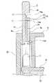
ベースシャーシ5の下端部には保持部材32が取り付けられる(図3及び図4参照)。保持部材32は厚みの薄い板状の金属材料が所定の形状に折り曲げられることによって形成され(図12参照)、上下方向を向く下面部33と該下面部33の前後両側縁から上方へ突出された突面部34、34とから成る。下面部33には、左右両端寄りの位置に、それぞれ3つずつの挿入孔35、35、・・・が形成されている。挿入孔35、35、35はそれぞれ幅広部35a、35a、・・・と該幅広部35a、35a、・・・より前後の幅が小さい幅狭部35b、35b、・・・とが左右に連続して成る。 A holding
保持部材32はベースシャーシ5に形成された取付用切欠10bを覆うようにして取り付けられる。保持部材32がベースシャーシ5に取り付けられた状態においては、下面部33とベースシャーシ5の下面との間に一定の隙間が形成される(図13参照)。保持部材32がベースシャーシ5に取り付けられた状態においては、挿入孔32、32、・・・の幅狭部32b、32b、・・・がベースシャーシ5の保持凹部10c、10c、10cの真下に位置される。 The holding
保持部材32には載置用パッド36、36が取り付けられる(図12参照)。載置用パッド36は上下方向を向く板状に形成された載置面部37と該載置面部37から上方へ突出された被保持部38、38、38とがゴム等の弾性を有する材料によって一体に形成されて成る。被保持部38、38、38は左右に離隔して設けられ、それぞれ被挿入部38a、38a、38aと該被挿入部38a、38a、38aより前後方向における幅が小さい括れ部38b、38b、38bとが上下に連続して成る。括れ部38b、38b、38bの前後幅は、それぞれ保持部材32の幅狭部35b、35b、35bの前後幅と略同じ幅に形成されている。 Mounting
載置用パッド36は以下のようにして保持部材32に取り付けられる(図14及び図15参照)。 The mounting
先ず、保持部材32がベースシャーシ5に取り付けられた状態(図13参照)において、載置用パッド36の被保持部38、38、38をそれぞれ保持部材32の挿入孔35、35、35の幅広部35a、35a、35aに挿入し、被保持部38、38、38をベースシャーシ5の下面に下方から強く押し付ける。 First, in a state where the holding
被保持部38、38、38をベースシャーシ5の下面に下方から強く押し付けると、被保持部38、38、38が弾性変形され上下方向において潰れた形状とされる(図14参照)。 When the held
この状態で載置用パッド36を側方へスライドさせると、括れ部38b、38b、38bがそれぞれ幅狭部35b、35b、35bに挿入され、被挿入部38a、38a、38aがそれぞれベースシャーシ5の保持凹部10c、10c、10cに対応して位置される。従って、被保持部38、38、38が弾性復帰して、それぞれ被挿入部38a、38a、38aが保持凹部10c、10c、10cに挿入され(図15参照)、載置用パッド36が保持部材32に取り付けられる。 When the mounting
保持部材32、32に取り付けられた載置用パッド36、36の載置面部37、37は、後述するように、電子機器1が机上等の載置面に載置された状態において該載置面に接する。 The mounting
このように、電子機器1にあっては、ベースシャーシ5の下端部に保持部材32を取り付け、該保持部材32に弾性を有する載置用パッド36、36を取り付け、電子機器1が机上等の載置面に載置された状態において該載置面に載置面部37、37が接するようにしているため、電子機器1の載置面に対する載置状態の安定化を図ることができる。 As described above, in the
また、載置用パッド36、36が載置面に接するため、載置面及びベースシャーシ5の下端部の傷付きや損傷を防止することができる。 Further, since the mounting
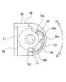
リアカバー8のスタンド支持部29にはスタンド4が回動機構39によって回動自在に支持される(図1乃至図4参照)。 The
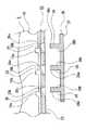
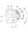
回動機構39は、図16及び図17に示すように、装置本体2に固定される本体側被固定部40と、スタンド4に固定されるスタンド側被固定部41、41と、本体側被固定部40とスタンド側被固定部41を連結する回動軸42、43とを有している。 As shown in FIGS. 16 and 17, the
本体側被固定部40は被固定板44と該被固定板44の後面に取り付けられた軸受部材45、46とから成り、該軸受部材45、46は左右に離隔して位置されている。 The body-side fixed
被固定板44は装置本体2の内部において固定される被固定部44aと該被固定部44aの左右両側縁からそれぞれ後方へ突出された軸支持突部44b、44cとから成る。 The fixed
軸受部材45は、被固定板44に取り付けられた被取付板部45aと、該被取付板部45aの一方の側縁から後方へ突出された軸受部45bとから成る。 The bearing
軸受部材46は、被固定板44に取り付けられた被取付板部47と、該被取付板部47の一方の側縁から後方へ突出された軸受部48と、該軸受部48の右側面に設けられたロック部49とから成る。 The bearing
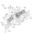
ロック部49は周方向に離隔して設けられた3つの規制部によって構成され、図18に示すように、該規制部は、上方側から順に第1の規制部50、第2の規制部51及び第3の規制部52とされている。第1の規制部50の周方向における反対側の面は、図18の拡大図に示すように、それぞれ第1の規制面50a及び第2の規制面50bとして形成されている。第1の規制面50aは右方へ行くに従って第2の規制面50bに近付く傾斜面に形成されている。第1の規制部50と第2の規制部51は左右方向において同じ位置に存在するが、第3の規制部52は第1の規制部50と第2の規制部51より右方に位置されている。 The
回動軸42、43は左右方向に延び、図16及び図17に示すように、それぞれ被固定板44の軸支持突部44b、44cに挿入され、軸受部材45、46の軸受部45b、48に軸回り方向へ回転自在に支持されている。回動軸42、43は軸受部45b、48に支持された状態において、一部が軸受部45b、48からそれぞれ外方へ突出されている。 The
回動軸42、43の軸方向における外側の端部には、それぞれスタンド側被固定部41、41が取り付けられている。スタンド側被固定部41は被固定部41a、41aと該被固定部41a、41aの内側の側縁からそれぞれ前方へ突出された被取付突部41b、41bとから成る。スタンド側被固定部41、41は、被固定部41a、41aがスタンド4の内部において固定され、被取付突部41b、41bがそれぞれ回動軸42、43に取り付けられている。 Stand side fixed
回動軸42、43にはそれぞれコイルバネであるバネ部材53、53が支持されている。バネ部材53、53は、それぞれ一端部が軸受部材45、46の軸受部45b、48に支持され、他端部がスタンド側被固定部41、41の被取付突部41b、41bに支持されている。従って、スタンド側被固定部41、41はバネ部材53、53によって本体側被固定部40に対して回動軸42、43の軸回り方向における一方向(図7に示すR1方向)、即ち、スタンド4の下端部が装置本体2の下端部に近付く方向への回動力が付与される。
左側に位置する回動軸43には被規制部材54が軸回り方向へ回転不能かつ軸方向へ移動自在に支持されている。 A
被規制部材54は、図18に示すように、略円環状に形成された軸挿通部55と該軸挿通部55の外周部の一部から左方へ突出された突出部56とから成る。突出部56の内面における左端部にはそれぞれ突状の第1の被規制部56aと第2の被規制部56bが設けられ、第1の被規制部56aと第2の被規制部56bは周方向に離隔して位置されている。 As shown in FIG. 18, the
被規制部材54は軸挿通部55に回動軸43が挿通され、該回動軸43の右端部、即ち、軸受部材46から右方へ突出された部分に支持されている。 The
上記のように、被規制部材54は回動軸43に軸回り方向へ回転不能に支持されているため、バネ部材53によって回動軸43に付与される回動力と同じ方向へ、バネ部材53によって付勢されている。 As described above, since the
回動軸43には回動角度変更レバー57が軸回り方向へ回転不能かつ軸方向へ移動自在に支持されている(図16及び図17参照)。 A rotation
回動角度変更レバー57は略上下方向を向くベース面部57aと該ベース面部57aから下方へ突出された被操作部57bとベース面部57aから上方へ突出された被支持筒部57cとから成る。回動角度変更レバー57は被支持筒部57cに回動軸43が挿通され、該回動軸43に軸回り方向へ回転可能かつ軸方向へ移動自在に支持されている。回動角度変更レバー57は被支持筒部57cが被規制部材54の軸挿通部55と軸受部材46の軸受部48との間に位置され、ベース面部57a及び被操作部57bが被規制部材54の下側に位置されている。 The rotation
回動角度変更レバー58は操作方向における左端である第1の操作位置と操作方向における右端である第2の操作位置との間で移動可能とされ、被操作部57bがリアカバー8のスタンド支持部29の外方に位置され、手動操作可能な状態とされている。 The rotation
回動軸43の右端部にはストッパーリング58が固定されている。ストッパーリング58と被規制部材54の軸挿通部55との間には圧縮コイルバネである付勢バネ59が支持されている。従って、被規制部材54は付勢バネ59によって軸受部材46の軸受部48に近付く方向へ付勢されている。 A
以下に、回動機構の動作及びこれに伴うスタンド4の動作について説明する(図19乃至図30参照)。 Below, operation | movement of a rotation mechanism and operation | movement of the
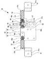
装置本体2に対するスタンド4の回動可能角度のモードとしては第1のモードと第2のモードがあり、第1のモードは電子機器1をパーソナルコンピューターとして通常使用するモードであり、第2のモードは電子機器1のパーソナルコンピューターとしての非使用時、例えば、持ち運び時やメンテナンス時のモードである。第1のモードにおいては、例えば、スタンド4が装置本体2に対して30°乃至60°の範囲(第1の回動可能角度)で回動可能とされ、第2のモードにおいては、例えば、スタンド4が装置本体2に対して0°乃至90°の範囲(第2の回動可能角度)で回動可能とされる。 There are a first mode and a second mode as the rotation angle of the
第1のモードにおいては、図19に示すように、被規制部材54及び回動角度変更レバー57は付勢バネ59の付勢力によって移動範囲における左端、即ち、第1の操作位置にあり、被規制部材54の軸挿通部55が回動角度変更レバー57のベース面部57aに右方から押し付けられると共に被規制部材54の突出部56が軸受部材46の軸受部48に右方から押し付けられている。 In the first mode, as shown in FIG. 19, the
第1のモードにおいてスタンド4の回動角度が30°の状態では、図20に示すように、軸受部材46のロック部49の第2の規制部51に被規制部材54の第2の被規制部56bが上方から係合され、スタンド4が装置本体2に対して30°の状態に保持されている(図21参照)。 In the state where the rotation angle of the
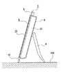
このとき電子機器1は、ベースシャーシ5の下端部に設けられた載置用パッド36、36とスタンド4の下端とが机上等の載置面100に接した状態で載置される。尚、電子機器1にあっては、保持部材32及び該保持部材32に取り付けられる載置パッド36、36を設けずに、ベースシャーシ5の下端とスタンド4の下端によって支え、載置面100に載置することも可能である。 At this time, the
上記のように、電子機器1にあっては、ベースシャーシ5とスタンド4に支えられて載置面100に載置されるため、ベースシャーシ5の他に専用の支えを設ける必要がなく、部品点数の削減及び構造の簡素化を図ることができる。 As described above, the
第1のモードにおいて、例えば、装置本体2に対するスタンド4の回動角度を30°より大きな角度となるように装置本体2を傾斜していくと、回動軸42、43がバネ部材53、53の付勢力に抗して図20に示すR2方向へ回転され、同時に被規制部材54が回動軸43と一体となって回転される。 In the first mode, for example, when the apparatus
被規制部材54は第1の被規制部56aがロック部49の第1の規制部50の第2の規制面50bに接するまで回転可能とされる。第1の被規制部56aが第1の規制部50の第2の規制面50bに接した状態(図22参照)が、装置本体2に対するスタンド4の回動角度が60°の状態である(図23参照)。 The
逆に、第1のモードにおいて、装置本体2に対するスタンド4の回動角度を60°より小さな角度となるように装置本体2を傾斜していくと、回動軸42、43がバネ部材53、53の付勢力によって図22に示すR1方向へ回転され、同時に被規制部材54が回動軸43と一体となって回転される。このとき、スタンド4は下端部が装置本体2の下端部に近付く方向へ付勢されているため、装置本体2の角度変更に追従してスタンド4が載置面100に接しながら回動される。従って、装置本体2の角度調節をした後にスタンド4の下端部が装置本体2に近付く方向へ手動で回動させる必要がなく、利便性の向上を図ることができる。 Conversely, in the first mode, when the apparatus
第1のモードにおいては、上記のようにスタンド4の回動角度を30°から60°の範囲で変更可能であり、このとき常にスタンド4に回動軸42、43を介してバネ部材53、53のR1方向への付勢力が付与されているが、電子機器1にあっては、スタンド4と載置面100との間の摩擦力や電子機器1の自重によって載置面100に対して付与される力が、バネ部材53、53の付勢力に打ち勝つように設定されているため、上記した30°乃至60°の範囲内でスタンド4を載置面100に対して滑ることなく任意の角度に保持することが可能とされている。 In the first mode, the rotation angle of the
装置本体2に対するスタンド4の回動角度が30°乃至60°の範囲内で保持されている状態において、回動角度変更レバー57を操作して第1の操作位置から第2の操作位置まで右方へ移動させると、第2のモードが設定される(図24参照)。 In a state where the rotation angle of the
第2のモードは、上記したように、電子機器1の非使用時やメンテナンス時のモードであるため、通常、スタンド4を用いては電子機器1を載置面100に載置させない状態、例えば、表示ユニット6を載置面100に接するようにして載置した状態(図25参照)で設定される。 As described above, since the second mode is a mode when the
回動角度変更レバー57を右方へ移動させるときには、該回動角度変更レバー57のベース面部57aによって被規制部材54の軸挿通部55が押圧されて被規制部材54が右方へ移動される。 When the rotation
回動角度変更レバー57を第2の操作位置まで移動させると、被規制部材54の第1の被規制部56a及び第2の被規制部56bがロック部49の第1の規制部50及び第2の規制部51から右方へ離隔した位置に移動されるため、スタンド4を把持しない状態においては、被規制部材54がバネ部材53の付勢力によってR1方向へ回転され、第2の被規制部56bがロック部49の第3の規制部52に接して押し付けられる(図26参照)。 When the rotation
第2の被規制部56bが第3の規制部52に接した状態において、回動角度変更レバー57に対する手動による操作を解除すると、付勢バネ59によって被規制部材54に左方への移動力が付与され、第2の被規制部56bがロック部49の第2の規制部51に側方から押し付けられる。従って、回動角度変更レバー57は第2の操作位置に保持される。 In the state where the second restricted
第2の被規制部56bがロック部49の第3の規制部52に接した状態が、装置本体2に対するスタンド4の回動角度が0°の状態である(図27参照)。装置本体2に対するスタンド4の回動角度が0°の状態においては、スタンド4が装置本体2から斜め方向へ突出されないため、例えば、電子機器1の持ち運び時にスタンド4が邪魔とならず、持ち運び等の利便性の向上を図ることができる。 The state in which the second restricted
尚、上記には、被規制部材54の第2の被規制部56bがロック部49の第3の規制部52に接して押し付けられることによりスタンド4を回動角度0°に保持する例を示したが、例えば、スタンド4が装置本体2の背面2aに接することによりスタンド4を回動角度0°に保持するようにすることも可能である。 In the above, an example is shown in which the second
このようにスタンド4が装置本体2の背面2aに接することによりスタンド4を回動角度0°に保持することにより、スタンド4を0°の状態に保持するための専用の規制部を必要とせず、部品点数の削減及び機構の簡素化を図ることができる。 In this way, the
スタンド4の回動角度が0°の状態において、スタンド4を装置本体2に対する回動角度が大きくなる方向へ回動していくと、被規制部材54の第2の被規制部56bがロック部49の第2の規制部51の右側面と摺接され、第2の被規制部56bが第2の規制部51から離隔されたところで付勢バネ59の付勢力によって被規制部材54が左方へ移動される。被規制部材54の左方への移動によって回動角度変更レバー57の被支持筒部57cが軸挿通部55によって左方へ押圧され、回動角度変更レバー57が第2の操作位置から第1の操作位置まで移動される。 When the rotation angle of the
このようにスタンド4を0°の状態から回動させたときに、付勢バネ59によって回動角度変更レバー57を第2の操作位置から第1の操作位置へ移動させることにより、回動角度変更レバー57を手動操作により第2の操作位置から第1の操作位置に移動させる必要がなく、操作性の向上を図ることができる。 Thus, when the
回動角度変更レバー57を第2の操作位置まで移動させると、被規制部材54の第1の被規制部56a及び第2の被規制部56bがロック部49の第1の規制部50及び第2の規制部51から右方へ離隔した位置に移動されるため、スタンド4を把持し該スタンド4の下端部が装置本体2の下端部から離隔する方向へ90°の状態まで回動させることが可能となる。 When the rotation
スタンド4を90°の状態まで回動し、第2の操作位置に保持していた回動角度変更レバー57の手動による操作を解除すると、付勢バネ59の付勢力によって被規制部材54及び回動角度変更レバー57が左方へ移動され、該回動角度変更レバー57が第2の操作位置から第1の操作位置まで移動される。 When the
被規制部材54が左方へ移動されると、第1の被規制部56aがロック部49の第1の規制部50の上側に位置される。このときスタンド4に対する手動による回動動作を解除すると、バネ部材53、53の付勢力によってスタンド4に回動角度0°の方向へ回動する向きの回動力が付与され、第1の被規制部56aが第1の規制部50の第1の規制面50aに押し付けられて係合する(図28参照)。従って、スタンド4は装置本体2に対する回動角度が90°の状態に保持される(図29参照)。 When the
装置本体2に対するスタンド4の回動角度が90°の状態においては、スタンド4がリアカバー8のメンテナンス用開口27aを開閉する蓋30の開閉動作に邪魔とならず、蓋30の開閉を容易に行うことができる。 When the rotation angle of the
また、メンテナンス用開口27aを介してのメンテナンス時にもスタンド4が邪魔となることがなく、メンテナンスを容易に行うことができる。 In addition, the
装置本体2に対するスタンド4の回動角度が90°で保持されている状態において、回動角度変更レバー57を第1の操作位置から操作して第2の操作位置まで右方へ移動させると、第1のモードが設定される。 When the rotation angle of the
回動角度変更レバー57が第2の操作位置まで移動されるときには、被規制部材54の第1の被規制部56aがロック部49の第1の規制部50の第1の規制面50aと摺動される(図30参照)。このとき被規制部材54はバネ部材53、53の付勢力によって第1の被規制部56aが第1の規制面50aに押し付けられているが、該第1の規制面50aが傾斜面に形成されているため、被規制部材54及び回動角度変更レバー57が右方へ向けて円滑に移動され、第1の被規制部56aと第1の規制面50aの接触が解除される。 When the rotation
従って、回動角度変更レバー57の第1の操作位置から第2の操作位置へ向けての操作を円滑に行うことができる。 Therefore, the operation of the rotation
第1の被規制部56aと第1の規制面50aの接触が解除されたときに、回動角度変更レバー57に対する手動による操作を解除すると、付勢バネ59によって被規制部材54に左方への移動力が付与され、該被規制部材54と回動角度変更レバー57が一体となって左方へ移動される。被規制部材54は第1の被規制部56a及び第2の被規制部56bがともにロック部49の第1の規制部50と第2の規制部51の間に位置され、被規制部材54がバネ部材53の付勢力によって回転されることにより第2の被規制部56bが第2の規制部51に接して係合され、被規制部材54の回転が停止される(図20参照)。 When the contact between the first restricted
従って、第1のモードが設定され、スタンド4は装置本体2に対する回動角度が30°の状態に保持される(図21参照)。回動角度変更レバー57は第1の操作位置に保持される(図19参照)。 Accordingly, the first mode is set, and the
以上に記載した通り、電子機器1にあっては、回動角度変更レバー57を操作することにより第1のモードと第2のモードの切替を行うことができ、電子機器1をパーソナルコンピューターとして通常使用することができる他、電子機器1のパーソナルコンピューターとしての非使用時、例えば、持ち運び時やメンテナンス時のモードを簡単に設定することができる。 As described above, in the
また、第2のモードにおいてスタンド4の角度を0°から90°まで変更することが可能であるため、電子機器1に対する必要な作業、例えば、持ち運びやメンテナンスを不都合なく容易に行うことができる。 In addition, since the angle of the
ベースシャーシ5の配置用切欠10aにはカメラユニット60が配置されている(図1乃至図4参照)。カメラユニット60は、例えば、テレビ電話用であり、横長の形状に形成され、ベースシャーシ5に図示しないヒンジ機構によって左右に延びる支点軸を介して回動自在に支持されている。カメラユニット60のベースシャーシ5に対する回動可能角度は、例えば、基準位置に対して±10°とされ、カメラユニット60を回動可能角度の範囲内において任意の角度で保持することが可能とされている。 A
カメラユニット60の前面には撮影用レンズ60aが設けられている。撮影用レンズ60aの画角は、例えば、55°とされている(図31参照)。撮影用レンズ60aの光軸方向は、以下のように設定されている。 A photographing
使用者101が電子機器1を使用する際の標準的な使用状態は、一般に、図31に示すように、椅子102の高さが40cm、机103の高さが70cm、使用者101の床104からの目の高さが120cmとされる。 As shown in FIG. 31, the standard use state when the
机102上に載置された電子機器1は、表示パネルの表示面が垂直方向に対して25°の角度で傾斜され、使用者101は表示パネルの表示面を85°の角度から視認している。 In the
カメラユニット60の上記基準位置、即ち、基準状態における撮影用レンズ60aの光軸方向Sは、表示パネル21の法線Lに対して稍下向き、例えば、7°下向きに設定されている。従って、カメラユニット60は7°下向きの状態を基準として、±10°の範囲で回動可能とされている。 The reference position of the
このように基準位置においてカメラユニット60を法線Lに対して下向き、例えば、7°下向きの状態とすることにより、相手先の機器における表示画面の中央部に使用者101の顔が映し出され易く、テレビ電話等の使用時における使い勝手の向上を図ることができる。 In this way, by setting the
また、電子機器1にあっては、カメラユニット60がベースシャーシ5に対して回動可能とされているため、映像の位置調整を行うことができる。 In the
尚、上記に示した前後上下左右の方向は説明の便宜上のものであり、本発明の適用においては、これらの方向に限定されることはない。 It should be noted that the front, rear, up, down, left, and right directions shown above are for convenience of explanation, and the application of the present invention is not limited to these directions.
上記した最良の形態において示した各部の具体的な形状及び構造は、何れも本発明を実施する際の具体化のほんの一例を示したものにすぎず、これらによって本発明の技術的範囲が限定的に解釈されることがあってはならないものである。 The specific shapes and structures of the respective parts shown in the above-described best mode are merely examples of the implementation of the present invention, and the technical scope of the present invention is limited by these. It should not be interpreted in a general way.
1…電子機器、4…スタンド、5…ベースシャーシ、5a…第1の取付面部、5b…第2の取付面部、6…表示ユニット、7…制御回路基板、8…リアカバー、9…取付用凹部、10…外周部、11…底面部、12…連結部、21…表示パネル、32…保持部材、36…載置用パッド、100…載置面 DESCRIPTION OF
Claims (5)
Translated fromJapanese該ベースシャーシの第1の取付面部に表示パネルを有する表示ユニットを取り付け、
ベースシャーシの第2の取付面部に少なくとも制御回路基板と該制御回路基板を覆うリアカバーとを取り付けた
ことを特徴とする電子機器。Each part is integrally formed of a transparent material and has a base chassis in which both surfaces located on opposite sides are formed as a first mounting surface portion and a second mounting surface portion, respectively.
A display unit having a display panel is attached to the first attachment surface portion of the base chassis,
At least a control circuit board and a rear cover that covers the control circuit board are attached to the second attachment surface portion of the base chassis.
ベースシャーシを、上記外周部と、該外周部の内側に位置し外周部と平行な底面部と、外周部の内周縁と底面部の外周縁に連続し外周部及び底面部に対して折り曲げられた連結部とによって構成し、
上記表示パネルを取付用凹部に挿入して配置しベースシャーシに取り付けるようにした
ことを特徴とする請求項1に記載の電子機器。A mounting recess is formed in a portion excluding the outer peripheral portion of the first mounting surface portion of the base chassis,
The base chassis is bent with respect to the outer peripheral portion and the bottom surface portion continuously from the outer peripheral portion, the bottom surface portion located inside the outer peripheral portion and parallel to the outer peripheral portion, the inner peripheral edge of the outer peripheral portion and the outer peripheral edge of the bottom surface portion. With a connected part,
The electronic device according to claim 1, wherein the display panel is inserted and disposed in an attachment recess and attached to a base chassis.
ことを特徴とする請求項2に記載の電子機器。The electronic device according to claim 2, wherein a thickness of a bottom surface portion of the base chassis is formed thinner than a thickness of an outer peripheral portion.
該スタンドとベースシャーシによって支えて載置面に載置するようにした
ことを特徴とする請求項1に記載の電子機器。Provide a stand that is rotatably supported on the back of the rear cover,
The electronic apparatus according to claim 1, wherein the electronic apparatus is supported by the stand and the base chassis and placed on a placement surface.
該保持部材に、弾性を有し載置面に接する載置用パッドを取り付けた
ことを特徴とする請求項4に記載の電子機器。Attach the holding member to the lower end of the base chassis,
The electronic device according to claim 4, wherein a mounting pad that has elasticity and contacts the mounting surface is attached to the holding member.
Priority Applications (6)
| Application Number | Priority Date | Filing Date | Title |
|---|---|---|---|
| JP2006108660AJP2007279577A (en) | 2006-04-11 | 2006-04-11 | Electronic equipment |
| US11/687,742US8125771B2 (en) | 2006-04-11 | 2007-03-19 | Electronic apparatus |
| TW96109364ATWI331708B (en) | 2006-04-11 | 2007-03-19 | Electronic apparatus |
| KR1020070034848AKR20070101140A (en) | 2006-04-11 | 2007-04-10 | Electronic device |
| CN 200710096531CN101056507B (en) | 2006-04-11 | 2007-04-11 | Electronic apparatus |
| US13/355,021US9047043B2 (en) | 2006-04-11 | 2012-01-20 | Electronic apparatus |
Applications Claiming Priority (1)
| Application Number | Priority Date | Filing Date | Title |
|---|---|---|---|
| JP2006108660AJP2007279577A (en) | 2006-04-11 | 2006-04-11 | Electronic equipment |
Publications (1)
| Publication Number | Publication Date |
|---|---|
| JP2007279577Atrue JP2007279577A (en) | 2007-10-25 |
Family
ID=38574995
Family Applications (1)
| Application Number | Title | Priority Date | Filing Date |
|---|---|---|---|
| JP2006108660APendingJP2007279577A (en) | 2006-04-11 | 2006-04-11 | Electronic equipment |
Country Status (5)
| Country | Link |
|---|---|
| US (2) | US8125771B2 (en) |
| JP (1) | JP2007279577A (en) |
| KR (1) | KR20070101140A (en) |
| CN (1) | CN101056507B (en) |
| TW (1) | TWI331708B (en) |
Cited By (12)
| Publication number | Priority date | Publication date | Assignee | Title |
|---|---|---|---|---|
| JP2009259165A (en)* | 2008-04-21 | 2009-11-05 | Fujitsu Ltd | Electronic apparatus |
| JP2009259166A (en)* | 2008-04-21 | 2009-11-05 | Fujitsu Ltd | Electronics |
| JP2011081808A (en)* | 2009-10-12 | 2011-04-21 | Pegatron Corp | Desktop personal computer |
| JP2016516952A (en)* | 2013-03-28 | 2016-06-09 | マイクロソフト テクノロジー ライセンシング,エルエルシー | Hinge mechanism for mounting rotatable parts |
| JP2017157706A (en)* | 2016-03-02 | 2017-09-07 | レノボ・シンガポール・プライベート・リミテッド | Electronics |
| US9964998B2 (en) | 2014-09-30 | 2018-05-08 | Microsoft Technology Licensing, Llc | Hinge mechanism with multiple preset positions |
| US10013030B2 (en) | 2012-03-02 | 2018-07-03 | Microsoft Technology Licensing, Llc | Multiple position input device cover |
| US10037057B2 (en) | 2016-09-22 | 2018-07-31 | Microsoft Technology Licensing, Llc | Friction hinge |
| US10344797B2 (en) | 2016-04-05 | 2019-07-09 | Microsoft Technology Licensing, Llc | Hinge with multiple preset positions |
| US10606322B2 (en) | 2015-06-30 | 2020-03-31 | Microsoft Technology Licensing, Llc | Multistage friction hinge |
| US10678743B2 (en) | 2012-05-14 | 2020-06-09 | Microsoft Technology Licensing, Llc | System and method for accessory device architecture that passes via intermediate processor a descriptor when processing in a low power state |
| US10963087B2 (en) | 2012-03-02 | 2021-03-30 | Microsoft Technology Licensing, Llc | Pressure sensitive keys |
Families Citing this family (54)
| Publication number | Priority date | Publication date | Assignee | Title |
|---|---|---|---|---|
| JP2007279577A (en)* | 2006-04-11 | 2007-10-25 | Sony Corp | Electronic equipment |
| JP4725792B2 (en) | 2006-04-11 | 2011-07-13 | ソニー株式会社 | Electronics |
| US20080243970A1 (en)* | 2007-03-30 | 2008-10-02 | Sap Ag | Method and system for providing loitering trace in virtual machines |
| TW200951680A (en)* | 2008-06-04 | 2009-12-16 | Pegatron Corp | Desktop computer and manufacturing method thereof |
| JP2011081213A (en)* | 2009-10-07 | 2011-04-21 | Fujitsu Ltd | Image display panel, electronic apparatus, and disassembly method of image display panel |
| JP5218367B2 (en)* | 2009-10-07 | 2013-06-26 | 富士通株式会社 | Cable wiring structure and electronic equipment |
| JP2011081212A (en)* | 2009-10-07 | 2011-04-21 | Fujitsu Ltd | Electronic device |
| JP5263113B2 (en)* | 2009-10-07 | 2013-08-14 | 富士通株式会社 | Electronics |
| US8649166B2 (en)* | 2011-01-11 | 2014-02-11 | Z124 | Multi-positionable portable computer |
| US8648821B2 (en) | 2011-01-18 | 2014-02-11 | Flextronics Id, Llc | Spheroidal pivot for an electronic device |
| US8526178B2 (en) | 2011-05-17 | 2013-09-03 | Flextronics Ap, Llc | All-in-one computing device with an adjustable screen height |
| JP2012253094A (en)* | 2011-05-31 | 2012-12-20 | Sony Corp | Electronic apparatus |
| US8681113B1 (en) | 2011-09-27 | 2014-03-25 | Flextronics Ap, Llc | Concept and operation mode for multi media AIO |
| WO2013058978A1 (en) | 2011-10-17 | 2013-04-25 | Kimmel Zebadiah M | Method and apparatus for sizing and fitting an individual for apparel, accessories, or prosthetics |
| US9974466B2 (en) | 2011-10-17 | 2018-05-22 | Atlas5D, Inc. | Method and apparatus for detecting change in health status |
| US9817017B2 (en) | 2011-10-17 | 2017-11-14 | Atlas5D, Inc. | Method and apparatus for monitoring individuals while protecting their privacy |
| US9354748B2 (en) | 2012-02-13 | 2016-05-31 | Microsoft Technology Licensing, Llc | Optical stylus interaction |
| US9706089B2 (en) | 2012-03-02 | 2017-07-11 | Microsoft Technology Licensing, Llc | Shifted lens camera for mobile computing devices |
| US9064654B2 (en) | 2012-03-02 | 2015-06-23 | Microsoft Technology Licensing, Llc | Method of manufacturing an input device |
| US9298236B2 (en) | 2012-03-02 | 2016-03-29 | Microsoft Technology Licensing, Llc | Multi-stage power adapter configured to provide a first power level upon initial connection of the power adapter to the host device and a second power level thereafter upon notification from the host device to the power adapter |
| US8873227B2 (en) | 2012-03-02 | 2014-10-28 | Microsoft Corporation | Flexible hinge support layer |
| US9870066B2 (en) | 2012-03-02 | 2018-01-16 | Microsoft Technology Licensing, Llc | Method of manufacturing an input device |
| US9426905B2 (en) | 2012-03-02 | 2016-08-23 | Microsoft Technology Licensing, Llc | Connection device for computing devices |
| US9360893B2 (en) | 2012-03-02 | 2016-06-07 | Microsoft Technology Licensing, Llc | Input device writing surface |
| USRE48963E1 (en) | 2012-03-02 | 2022-03-08 | Microsoft Technology Licensing, Llc | Connection device for computing devices |
| US8922983B1 (en)* | 2012-03-27 | 2014-12-30 | Amazon Technologies, Inc. | Internal metal support structure for mobile device |
| US8861198B1 (en) | 2012-03-27 | 2014-10-14 | Amazon Technologies, Inc. | Device frame having mechanically bonded metal and plastic |
| US8804321B2 (en) | 2012-05-25 | 2014-08-12 | Steelcase, Inc. | Work and videoconference assembly |
| US10031556B2 (en) | 2012-06-08 | 2018-07-24 | Microsoft Technology Licensing, Llc | User experience adaptation |
| US9019615B2 (en) | 2012-06-12 | 2015-04-28 | Microsoft Technology Licensing, Llc | Wide field-of-view virtual image projector |
| US8964379B2 (en) | 2012-08-20 | 2015-02-24 | Microsoft Corporation | Switchable magnetic lock |
| US20140226267A1 (en)* | 2013-02-12 | 2014-08-14 | Panasonic Corporation | Display device |
| US9835933B2 (en) | 2013-02-18 | 2017-12-05 | Sony Interactive Entertainment Inc. | Camera and camera assembly |
| US9468112B2 (en)* | 2013-08-09 | 2016-10-11 | Shenzhen China Star Optoelectronics Technology Co., Ltd. | Display device with narrow frame |
| US9317072B2 (en) | 2014-01-28 | 2016-04-19 | Microsoft Technology Licensing, Llc | Hinge mechanism with preset positions |
| US10120420B2 (en) | 2014-03-21 | 2018-11-06 | Microsoft Technology Licensing, Llc | Lockable display and techniques enabling use of lockable displays |
| US10324733B2 (en) | 2014-07-30 | 2019-06-18 | Microsoft Technology Licensing, Llc | Shutdown notifications |
| US9424048B2 (en) | 2014-09-15 | 2016-08-23 | Microsoft Technology Licensing, Llc | Inductive peripheral retention device |
| KR101643402B1 (en)* | 2015-01-14 | 2016-08-10 | 주식회사 뉴트리케어 | Cleansing apparatus |
| US10013756B2 (en) | 2015-03-13 | 2018-07-03 | Atlas5D, Inc. | Methods and systems for measuring use of an assistive device for ambulation |
| US9752361B2 (en) | 2015-06-18 | 2017-09-05 | Microsoft Technology Licensing, Llc | Multistage hinge |
| CN105007402B (en)* | 2015-07-03 | 2018-01-23 | 广东欧珀移动通信有限公司 | Mobile terminal |
| CN105049557B (en)* | 2015-07-03 | 2018-12-11 | 广东欧珀移动通信有限公司 | Terminal |
| DE202016101176U1 (en)* | 2016-03-04 | 2016-06-03 | Omron Corporation | Housing for a monitor of an industrial computer, monitor for an industrial computer and industrial computer |
| US9888594B1 (en)* | 2016-09-30 | 2018-02-06 | Hewlett Packard Enterprise Development Lp | Devices including a cavity region to house ports |
| WO2018093093A1 (en)* | 2016-11-18 | 2018-05-24 | 주식회사 포스뱅크 | Hinge coupling structure for pos device |
| KR101826345B1 (en) | 2016-11-30 | 2018-02-06 | 주식회사 포스뱅크 | POS Apparatus |
| CN108319327A (en)* | 2017-01-16 | 2018-07-24 | 晶达光电股份有限公司 | Suspension type display structure |
| JP6563965B2 (en)* | 2017-01-31 | 2019-08-21 | 矢崎総業株式会社 | Vehicle display device |
| TWI673545B (en)* | 2018-06-21 | 2019-10-01 | 兆利科技工業股份有限公司 | A Hinge Module For The Foldable Type Device |
| US10829039B2 (en)* | 2019-02-18 | 2020-11-10 | Visteon Global Technologies, Inc. | Display arrangement for an instrument cluster |
| KR102730876B1 (en)* | 2019-06-04 | 2024-11-18 | 삼성전자주식회사 | Display apparatus |
| CN112105218B (en)* | 2019-06-17 | 2022-02-25 | 华为技术有限公司 | Foldable electronic equipment and pivoting type heat dissipation device thereof |
| US11334120B2 (en)* | 2020-07-21 | 2022-05-17 | Dell Products L.P. | Information handling system kickstand hinge |
Citations (10)
| Publication number | Priority date | Publication date | Assignee | Title |
|---|---|---|---|---|
| JPH0396746U (en)* | 1990-01-25 | 1991-10-03 | ||
| JPH10312160A (en)* | 1997-05-14 | 1998-11-24 | Kunihiko Koike | Display device |
| JP2000340991A (en)* | 1999-05-31 | 2000-12-08 | Sony Corp | Display device |
| JP2002260426A (en)* | 2001-02-28 | 2002-09-13 | Sharp Corp | Display device and lighting device |
| JP2003029649A (en)* | 2001-07-10 | 2003-01-31 | Samsung Electronics Co Ltd | Liquid crystal display |
| JP2005070662A (en)* | 2003-08-27 | 2005-03-17 | Sony Corp | Panel type display device |
| JP2005070661A (en)* | 2003-08-27 | 2005-03-17 | Sony Corp | Panel type display device |
| JP2005136651A (en)* | 2003-10-30 | 2005-05-26 | Sharp Corp | Thin display device |
| JP2006030313A (en)* | 2004-07-12 | 2006-02-02 | Sony Corp | Symbol illumination device and graphic display device |
| JP2006058587A (en)* | 2004-08-20 | 2006-03-02 | Sharp Corp | Thin display device |
Family Cites Families (48)
| Publication number | Priority date | Publication date | Assignee | Title |
|---|---|---|---|---|
| US305409A (en)* | 1884-09-16 | Davis tillsojt | ||
| US301640A (en)* | 1884-07-08 | George e | ||
| US5268816A (en)* | 1982-09-28 | 1993-12-07 | Lexmark International, Inc. | Movable display screen for a computer |
| US4748756A (en)* | 1987-01-23 | 1988-06-07 | Bruce Ross | Touch activated enhanced picture frame |
| JPH061422B2 (en)* | 1988-09-22 | 1994-01-05 | インターナショナル・ビジネス・マシーンズ・コーポレーション | Electronics with keyboard |
| DE3929753C1 (en) | 1989-09-07 | 1991-01-10 | Skf Gmbh, 8720 Schweinfurt, De | Fan belt tensioner for vehicle - has pivot arm with tension roller, cooperating with torsional damper(s) |
| USD324036S (en)* | 1989-12-06 | 1992-02-18 | Kabushi Kaisha Toshiba | Combined electronic computer and telephone |
| US5157585A (en)* | 1991-06-27 | 1992-10-20 | Compaq Computer Corporation | Compact AC-powerable portable computer having a CPU and expansion bay in an upper housing pivotally attached to a lower housing |
| JP3096746B2 (en) | 1992-01-06 | 2000-10-10 | 芝浦メカトロニクス株式会社 | vending machine |
| US5450221A (en)* | 1993-09-08 | 1995-09-12 | Delco Electronics Corporation | Compact liquid crystal display for instrument panel having a wrap around flexible printed circuit board and translucent web |
| US5570267A (en)* | 1995-07-12 | 1996-10-29 | Ma; Hsi-Kuang | Flat display module |
| JP2839085B2 (en)* | 1996-07-25 | 1998-12-16 | 日本電気株式会社 | Liquid crystal display |
| US5815225A (en)* | 1997-01-22 | 1998-09-29 | Gateway 2000, Inc. | Lighting apparatus for a portable computer with illumination apertures |
| KR100218581B1 (en)* | 1997-04-08 | 1999-09-01 | 구자홍 | Portable computer with LCD |
| US5887962A (en)* | 1997-07-17 | 1999-03-30 | Tsai; Kun-Ming | Foot adapted for stabilizing the bottom of a computer case |
| US5927673A (en)* | 1997-09-26 | 1999-07-27 | Ericsson Inc. | Adjustable viewing stand |
| KR100296829B1 (en)* | 1997-11-28 | 2001-10-24 | 윤종용 | Portable computer with shock protection structure of electronic system and shock protection structure of electronic system |
| JP4060441B2 (en)* | 1998-05-22 | 2008-03-12 | 東芝松下ディスプレイテクノロジー株式会社 | Flat panel display |
| US6028764A (en)* | 1998-09-28 | 2000-02-22 | Intel Corporation | Portable computer with separable screen |
| TW550428B (en)* | 1999-07-12 | 2003-09-01 | Nec Lcd Technologies Ltd | Flat panel display device and manufacturing method thereof |
| KR100603838B1 (en)* | 1999-09-20 | 2006-07-24 | 엘지.필립스 엘시디 주식회사 | Liquid crystal display |
| TW569059B (en)* | 1999-12-09 | 2004-01-01 | Samsung Electronics Co Ltd | Liquid crystal display device |
| JP3645770B2 (en)* | 2000-01-28 | 2005-05-11 | 株式会社日立製作所 | Liquid crystal display |
| JP2001249324A (en)* | 2000-03-03 | 2001-09-14 | Hitachi Ltd | Liquid crystal display |
| US6480372B1 (en)* | 2000-04-24 | 2002-11-12 | Microsoft Corporation | Computer with a hidden keyboard |
| JP3628235B2 (en)* | 2000-04-26 | 2005-03-09 | 株式会社アドバンスト・ディスプレイ | Display device |
| CN2446583Y (en) | 2000-06-21 | 2001-09-05 | 北京创纪电子有限公司 | Computer liquid crystal display |
| TWI286629B (en)* | 2000-07-20 | 2007-09-11 | Samsung Electronics Co Ltd | Liquid crystal display device and flexible circuit board |
| JP3501218B2 (en)* | 2000-08-11 | 2004-03-02 | 日本電気株式会社 | Flat panel display module and manufacturing method thereof |
| US20020149905A1 (en)* | 2001-04-11 | 2002-10-17 | Jackson, Louiss R. | Flat hanging computer |
| TW583529B (en)* | 2001-11-15 | 2004-04-11 | Wistron Corp | Liquid crystal display computer with a removable device frame |
| JP2004061922A (en)* | 2002-07-30 | 2004-02-26 | Sony Corp | Light reflection display method, light reflection display device and electronic equipment |
| JP3603885B2 (en) | 2002-08-02 | 2004-12-22 | ソニー株式会社 | Flat panel image display |
| US6776497B1 (en)* | 2002-11-19 | 2004-08-17 | Apple Computer, Inc. | Apparatuses and methods for illuminating a keyboard |
| TWM246656U (en)* | 2003-08-28 | 2004-10-11 | Quanta Comp Inc | Notebook computer having night illumination device |
| US7457120B2 (en)* | 2004-04-29 | 2008-11-25 | Samsung Sdi Co., Ltd. | Plasma display apparatus |
| KR100617116B1 (en)* | 2004-08-06 | 2006-08-31 | 엘지전자 주식회사 | Video display device |
| JP2006133555A (en)* | 2004-11-08 | 2006-05-25 | Seiko Epson Corp | Electro-optical device and electronic apparatus |
| TWM263516U (en)* | 2004-12-21 | 2005-05-01 | Hannspree Inc | Liquid crystal display (LCD) with night light function |
| JP4581726B2 (en)* | 2004-12-28 | 2010-11-17 | ソニー株式会社 | Display device and portable device |
| TWI250790B (en)* | 2005-01-07 | 2006-03-01 | Asustek Comp Inc | Display device having rotational image-capturing module |
| KR100765478B1 (en)* | 2005-08-12 | 2007-10-09 | 삼성전자주식회사 | Tape wiring board with holes formed therein, tape package and flat panel display using the same |
| JP2007279577A (en)* | 2006-04-11 | 2007-10-25 | Sony Corp | Electronic equipment |
| JP4725792B2 (en)* | 2006-04-11 | 2011-07-13 | ソニー株式会社 | Electronics |
| JP2007281345A (en)* | 2006-04-11 | 2007-10-25 | Sony Corp | Stand rotation mechanism, and electronic apparatus |
| JP4091959B2 (en)* | 2006-04-28 | 2008-05-28 | インターナショナル・ビジネス・マシーンズ・コーポレーション | Keyboard lighting device for portable computers |
| US8619040B2 (en)* | 2007-07-05 | 2013-12-31 | Sony Corporation | Electronic apparatus |
| US7929287B2 (en)* | 2007-07-05 | 2011-04-19 | Sony Corporation | Electronic apparatus |
- 2006
- 2006-04-11JPJP2006108660Apatent/JP2007279577A/enactivePending
- 2007
- 2007-03-19TWTW96109364Apatent/TWI331708B/ennot_activeIP Right Cessation
- 2007-03-19USUS11/687,742patent/US8125771B2/ennot_activeExpired - Fee Related
- 2007-04-10KRKR1020070034848Apatent/KR20070101140A/ennot_activeCeased
- 2007-04-11CNCN 200710096531patent/CN101056507B/ennot_activeExpired - Fee Related
- 2012
- 2012-01-20USUS13/355,021patent/US9047043B2/ennot_activeExpired - Fee Related
Patent Citations (10)
| Publication number | Priority date | Publication date | Assignee | Title |
|---|---|---|---|---|
| JPH0396746U (en)* | 1990-01-25 | 1991-10-03 | ||
| JPH10312160A (en)* | 1997-05-14 | 1998-11-24 | Kunihiko Koike | Display device |
| JP2000340991A (en)* | 1999-05-31 | 2000-12-08 | Sony Corp | Display device |
| JP2002260426A (en)* | 2001-02-28 | 2002-09-13 | Sharp Corp | Display device and lighting device |
| JP2003029649A (en)* | 2001-07-10 | 2003-01-31 | Samsung Electronics Co Ltd | Liquid crystal display |
| JP2005070662A (en)* | 2003-08-27 | 2005-03-17 | Sony Corp | Panel type display device |
| JP2005070661A (en)* | 2003-08-27 | 2005-03-17 | Sony Corp | Panel type display device |
| JP2005136651A (en)* | 2003-10-30 | 2005-05-26 | Sharp Corp | Thin display device |
| JP2006030313A (en)* | 2004-07-12 | 2006-02-02 | Sony Corp | Symbol illumination device and graphic display device |
| JP2006058587A (en)* | 2004-08-20 | 2006-03-02 | Sharp Corp | Thin display device |
Cited By (12)
| Publication number | Priority date | Publication date | Assignee | Title |
|---|---|---|---|---|
| JP2009259165A (en)* | 2008-04-21 | 2009-11-05 | Fujitsu Ltd | Electronic apparatus |
| JP2009259166A (en)* | 2008-04-21 | 2009-11-05 | Fujitsu Ltd | Electronics |
| JP2011081808A (en)* | 2009-10-12 | 2011-04-21 | Pegatron Corp | Desktop personal computer |
| US10013030B2 (en) | 2012-03-02 | 2018-07-03 | Microsoft Technology Licensing, Llc | Multiple position input device cover |
| US10963087B2 (en) | 2012-03-02 | 2021-03-30 | Microsoft Technology Licensing, Llc | Pressure sensitive keys |
| US10678743B2 (en) | 2012-05-14 | 2020-06-09 | Microsoft Technology Licensing, Llc | System and method for accessory device architecture that passes via intermediate processor a descriptor when processing in a low power state |
| JP2016516952A (en)* | 2013-03-28 | 2016-06-09 | マイクロソフト テクノロジー ライセンシング,エルエルシー | Hinge mechanism for mounting rotatable parts |
| US9964998B2 (en) | 2014-09-30 | 2018-05-08 | Microsoft Technology Licensing, Llc | Hinge mechanism with multiple preset positions |
| US10606322B2 (en) | 2015-06-30 | 2020-03-31 | Microsoft Technology Licensing, Llc | Multistage friction hinge |
| JP2017157706A (en)* | 2016-03-02 | 2017-09-07 | レノボ・シンガポール・プライベート・リミテッド | Electronics |
| US10344797B2 (en) | 2016-04-05 | 2019-07-09 | Microsoft Technology Licensing, Llc | Hinge with multiple preset positions |
| US10037057B2 (en) | 2016-09-22 | 2018-07-31 | Microsoft Technology Licensing, Llc | Friction hinge |
Also Published As
| Publication number | Publication date |
|---|---|
| US8125771B2 (en) | 2012-02-28 |
| TWI331708B (en) | 2010-10-11 |
| TW200809465A (en) | 2008-02-16 |
| US9047043B2 (en) | 2015-06-02 |
| KR20070101140A (en) | 2007-10-16 |
| CN101056507A (en) | 2007-10-17 |
| US20070236873A1 (en) | 2007-10-11 |
| CN101056507B (en) | 2012-12-05 |
| US20120120580A1 (en) | 2012-05-17 |
Similar Documents
| Publication | Publication Date | Title |
|---|---|---|
| JP4725792B2 (en) | Electronics | |
| JP2007279577A (en) | Electronic equipment | |
| JP2007281345A (en) | Stand rotation mechanism, and electronic apparatus | |
| US6912122B2 (en) | Rotatable display fixing module | |
| US6587333B2 (en) | Flat panel display apparatus and tilt/swivel mechanism therein | |
| TWI669593B (en) | Adjustable display housing assembly | |
| CN101995920A (en) | Electronic equipment | |
| CN1734392A (en) | Electronic device with universal human-machine interface | |
| US9052583B2 (en) | Portable electronic device with multiple projecting functions | |
| US20030061684A1 (en) | Electronic apparatus | |
| JP2009128763A (en) | projector | |
| JP5102170B2 (en) | Electronics | |
| JP2013143603A (en) | Electronic apparatus | |
| JP4917517B2 (en) | Slide rotation mounting unit and mobile phone | |
| HK1109297B (en) | Electronic apparatus | |
| JP5431504B2 (en) | Electronics | |
| KR20100037837A (en) | Camera assembly for computer | |
| HK1109298B (en) | Pivoting mechanism for stand and eletronic apparatus | |
| JP2024152278A (en) | Electronics | |
| CN117628371A (en) | Electronic equipment | |
| JP2006065738A (en) | Information processing apparatus |
Legal Events
| Date | Code | Title | Description |
|---|---|---|---|
| A621 | Written request for application examination | Free format text:JAPANESE INTERMEDIATE CODE: A621 Effective date:20090330 | |
| A131 | Notification of reasons for refusal | Free format text:JAPANESE INTERMEDIATE CODE: A131 Effective date:20111111 | |
| A521 | Written amendment | Free format text:JAPANESE INTERMEDIATE CODE: A523 Effective date:20120106 | |
| A131 | Notification of reasons for refusal | Free format text:JAPANESE INTERMEDIATE CODE: A131 Effective date:20120501 | |
| A02 | Decision of refusal | Free format text:JAPANESE INTERMEDIATE CODE: A02 Effective date:20120918 |