JP2007279020A - Wearable electronic device and biometric apparatus using wearable electronic device - Google Patents
Wearable electronic device and biometric apparatus using wearable electronic deviceDownload PDFInfo
- Publication number
- JP2007279020A JP2007279020AJP2007032296AJP2007032296AJP2007279020AJP 2007279020 AJP2007279020 AJP 2007279020AJP 2007032296 AJP2007032296 AJP 2007032296AJP 2007032296 AJP2007032296 AJP 2007032296AJP 2007279020 AJP2007279020 AJP 2007279020A
- Authority
- JP
- Japan
- Prior art keywords
- light
- band
- light guide
- guide means
- electronic device
- Prior art date
- Legal status (The legal status is an assumption and is not a legal conclusion. Google has not performed a legal analysis and makes no representation as to the accuracy of the status listed.)
- Pending
Links
- 238000012549trainingMethods0.000claimsdescription58
- 239000004973liquid crystal related substanceSubstances0.000claimsdescription47
- 238000010894electron beam technologyMethods0.000claimsdescription11
- 230000036760body temperatureEffects0.000claimsdescription8
- 239000013307optical fiberSubstances0.000claimsdescription8
- 238000005259measurementMethods0.000claimsdescription7
- 238000003860storageMethods0.000claimsdescription7
- 230000007423decreaseEffects0.000claimsdescription5
- 230000035900sweatingEffects0.000claimsdescription4
- 210000004243sweatAnatomy0.000claimsdescription2
- 230000000694effectsEffects0.000abstractdescription16
- 238000013461designMethods0.000abstractdescription4
- 210000000707wristAnatomy0.000description33
- 238000005401electroluminescenceMethods0.000description21
- 238000010586diagramMethods0.000description18
- 230000006870functionEffects0.000description15
- 238000001514detection methodMethods0.000description14
- 230000008859changeEffects0.000description9
- 239000003086colorantSubstances0.000description9
- 230000002829reductive effectEffects0.000description8
- 239000011347resinSubstances0.000description8
- 229920005989resinPolymers0.000description8
- 150000002632lipidsChemical class0.000description7
- 238000000034methodMethods0.000description7
- 230000003287optical effectEffects0.000description7
- QVGXLLKOCUKJST-UHFFFAOYSA-Natomic oxygenChemical compound[O]QVGXLLKOCUKJST-UHFFFAOYSA-N0.000description6
- 235000014633carbohydratesNutrition0.000description6
- 150000001720carbohydratesChemical class0.000description6
- 239000000463materialSubstances0.000description6
- 239000011159matrix materialSubstances0.000description6
- 229910052760oxygenInorganic materials0.000description6
- 239000001301oxygenSubstances0.000description6
- 238000012545processingMethods0.000description6
- 230000002159abnormal effectEffects0.000description5
- 230000006872improvementEffects0.000description5
- 230000001133accelerationEffects0.000description4
- 238000005034decorationMethods0.000description4
- 230000000284resting effectEffects0.000description4
- AUNGANRZJHBGPY-SCRDCRAPSA-NRiboflavinChemical compoundOC[C@@H](O)[C@@H](O)[C@@H](O)CN1C=2C=C(C)C(C)=CC=2N=C2C1=NC(=O)NC2=OAUNGANRZJHBGPY-SCRDCRAPSA-N0.000description3
- 238000007796conventional methodMethods0.000description3
- 210000004247handAnatomy0.000description3
- 238000004519manufacturing processMethods0.000description3
- 230000004060metabolic processEffects0.000description3
- 102000004169proteins and genesHuman genes0.000description3
- 108090000623proteins and genesProteins0.000description3
- 241001481833Coryphaena hippurusSpecies0.000description2
- AUNGANRZJHBGPY-UHFFFAOYSA-ND-LyxoflavinNatural productsOCC(O)C(O)C(O)CN1C=2C=C(C)C(C)=CC=2N=C2C1=NC(=O)NC2=OAUNGANRZJHBGPY-UHFFFAOYSA-N0.000description2
- OAICVXFJPJFONN-UHFFFAOYSA-NPhosphorusChemical compound[P]OAICVXFJPJFONN-UHFFFAOYSA-N0.000description2
- 230000005540biological transmissionEffects0.000description2
- 230000004397blinkingEffects0.000description2
- 230000017531blood circulationEffects0.000description2
- 238000005253claddingMethods0.000description2
- 201000010099diseaseDiseases0.000description2
- 208000037265diseases, disorders, signs and symptomsDiseases0.000description2
- 238000005265energy consumptionMethods0.000description2
- 238000009434installationMethods0.000description2
- 230000031700light absorptionEffects0.000description2
- 210000003205muscleAnatomy0.000description2
- 229960002477riboflavinDrugs0.000description2
- 239000004925Acrylic resinSubstances0.000description1
- 229920000178Acrylic resinPolymers0.000description1
- PEDCQBHIVMGVHV-UHFFFAOYSA-NGlycerineChemical compoundOCC(O)COPEDCQBHIVMGVHV-UHFFFAOYSA-N0.000description1
- 241001465754MetazoaSpecies0.000description1
- 241000282579PanSpecies0.000description1
- 206010039203Road traffic accidentDiseases0.000description1
- VYPSYNLAJGMNEJ-UHFFFAOYSA-NSilicium dioxideChemical compoundO=[Si]=OVYPSYNLAJGMNEJ-UHFFFAOYSA-N0.000description1
- 239000004904UV filterSubstances0.000description1
- 229930003471Vitamin B2Natural products0.000description1
- 210000003423ankleAnatomy0.000description1
- 239000007864aqueous solutionSubstances0.000description1
- 238000000149argon plasma sinteringMethods0.000description1
- 230000000903blocking effectEffects0.000description1
- 230000036772blood pressureEffects0.000description1
- 210000004204blood vesselAnatomy0.000description1
- 238000009529body temperature measurementMethods0.000description1
- 210000005252bulbus oculiAnatomy0.000description1
- 230000000747cardiac effectEffects0.000description1
- 238000004891communicationMethods0.000description1
- 239000000470constituentSubstances0.000description1
- 230000008602contractionEffects0.000description1
- 238000012937correctionMethods0.000description1
- 230000007812deficiencyEffects0.000description1
- 238000011161developmentMethods0.000description1
- 235000005911dietNutrition0.000description1
- 230000037213dietEffects0.000description1
- 230000010339dilationEffects0.000description1
- 210000000624ear auricleAnatomy0.000description1
- 230000005611electricityEffects0.000description1
- 230000005284excitationEffects0.000description1
- 210000001508eyeAnatomy0.000description1
- 239000005262ferroelectric liquid crystals (FLCs)Substances0.000description1
- 239000011521glassSubstances0.000description1
- 230000036541healthEffects0.000description1
- 238000005286illuminationMethods0.000description1
- 230000002452interceptive effectEffects0.000description1
- 230000001678irradiating effectEffects0.000description1
- 230000001788irregularEffects0.000description1
- 210000003127kneeAnatomy0.000description1
- 239000010985leatherSubstances0.000description1
- 210000004185liverAnatomy0.000description1
- 230000007774longtermEffects0.000description1
- 230000005389magnetismEffects0.000description1
- 238000012423maintenanceMethods0.000description1
- 230000007257malfunctionEffects0.000description1
- 239000002184metalSubstances0.000description1
- 239000007769metal materialSubstances0.000description1
- 238000012986modificationMethods0.000description1
- 230000004048modificationEffects0.000description1
- 238000007747platingMethods0.000description1
- 230000002265preventionEffects0.000description1
- 230000004044responseEffects0.000description1
- 230000000717retained effectEffects0.000description1
- 235000019192riboflavinNutrition0.000description1
- 239000002151riboflavinSubstances0.000description1
- 238000007789sealingMethods0.000description1
- 230000008054signal transmissionEffects0.000description1
- 230000011664signalingEffects0.000description1
- 230000003068static effectEffects0.000description1
- 239000000126substanceSubstances0.000description1
- 235000000346sugarNutrition0.000description1
- 150000008163sugarsChemical class0.000description1
- 230000001052transient effectEffects0.000description1
- 230000000007visual effectEffects0.000description1
- 239000011716vitamin B2Substances0.000description1
- 235000019164vitamin B2Nutrition0.000description1
Images


Classifications
- A—HUMAN NECESSITIES
- A61—MEDICAL OR VETERINARY SCIENCE; HYGIENE
- A61B—DIAGNOSIS; SURGERY; IDENTIFICATION
- A61B5/00—Measuring for diagnostic purposes; Identification of persons
- A—HUMAN NECESSITIES
- A44—HABERDASHERY; JEWELLERY
- A44C—PERSONAL ADORNMENTS, e.g. JEWELLERY; COINS
- A44C5/00—Bracelets; Wrist-watch straps; Fastenings for bracelets or wrist-watch straps
- A44C5/0007—Bracelets specially adapted for other functions or with means for attaching other articles
- A44C5/0015—Bracelets specially adapted for other functions or with means for attaching other articles providing information, e.g. bracelets with calendars
- A—HUMAN NECESSITIES
- A61—MEDICAL OR VETERINARY SCIENCE; HYGIENE
- A61B—DIAGNOSIS; SURGERY; IDENTIFICATION
- A61B5/00—Measuring for diagnostic purposes; Identification of persons
- A61B5/68—Arrangements of detecting, measuring or recording means, e.g. sensors, in relation to patient
- A61B5/6801—Arrangements of detecting, measuring or recording means, e.g. sensors, in relation to patient specially adapted to be attached to or worn on the body surface
- A61B5/6802—Sensor mounted on worn items
- A61B5/681—Wristwatch-type devices
- A—HUMAN NECESSITIES
- A61—MEDICAL OR VETERINARY SCIENCE; HYGIENE
- A61B—DIAGNOSIS; SURGERY; IDENTIFICATION
- A61B5/00—Measuring for diagnostic purposes; Identification of persons
- A61B5/74—Details of notification to user or communication with user or patient; User input means
- A61B5/742—Details of notification to user or communication with user or patient; User input means using visual displays
- G—PHYSICS
- G04—HOROLOGY
- G04G—ELECTRONIC TIME-PIECES
- G04G17/00—Structural details; Housings
- G04G17/08—Housings
- G04G17/083—Watches distributed over several housings
- G—PHYSICS
- G04—HOROLOGY
- G04G—ELECTRONIC TIME-PIECES
- G04G9/00—Visual time or date indication means
Landscapes
- Life Sciences & Earth Sciences (AREA)
- Health & Medical Sciences (AREA)
- Physics & Mathematics (AREA)
- Heart & Thoracic Surgery (AREA)
- Molecular Biology (AREA)
- Pathology (AREA)
- Engineering & Computer Science (AREA)
- Biomedical Technology (AREA)
- Veterinary Medicine (AREA)
- Medical Informatics (AREA)
- Biophysics (AREA)
- Surgery (AREA)
- Animal Behavior & Ethology (AREA)
- General Health & Medical Sciences (AREA)
- Public Health (AREA)
- General Physics & Mathematics (AREA)
- Measuring Pulse, Heart Rate, Blood Pressure Or Blood Flow (AREA)
- Electric Clocks (AREA)
Abstract
Description
Translated fromJapanese本発明は、装着型電子機器を発光させる発光手段を備える装着型電子機器、例えば、電子腕時計などを構成するバンドや本体に発光手段を有するような装着型電子機器、および、装着型電子機器を用いた生体測定装置に関する。 The present invention relates to a wearable electronic device having light emitting means for emitting light from the wearable electronic device, for example, a wearable electronic device having a light emitting means in a band or a main body constituting an electronic wristwatch, and the wearable electronic device. The present invention relates to a biometric apparatus used.
また、本発明は、例えば、脈波を測定するため脈波測定装置、体温を測定するための体温測定装置、発汗度を測定するための発汗測定装置などを備えた装着型電子機器を用いた使用者の生体情報を測定する生体測定装置、特に、運動トレーニングを行う使用者へ助言を与える機能を備えた身体装着型運動トレーニング支援装置に関する。 Further, the present invention uses, for example, a wearable electronic device equipped with a pulse wave measuring device for measuring pulse waves, a body temperature measuring device for measuring body temperature, a sweat measuring device for measuring the degree of sweating, and the like. More particularly, the present invention relates to a body-worn exercise training support device having a function of giving advice to a user who performs exercise training.
電子腕時計においては、小型のランプやLED(Light Emitting Diode)、物質が励起源から得たエネルギーで光を放出するEL(Electro Luminescence)素子などの発光手段を備えており、暗い場所であっても表示装置を照射することによって、時刻情報などを読み取ることができる。 Electronic wristwatches are equipped with light-emitting means such as small lamps, LEDs (Light Emitting Diodes), and EL (Electro Luminescence) elements that emit light with energy obtained from the excitation source of the substance. Time information and the like can be read by irradiating the display device.
近年では、表示装置以外を照射するか、あるいは時計本体を発光させる機能を有する電子腕時計が提案されている。このような電子腕時計は、時計本体の側面などに発光手段を備え、懐中電灯のように周囲を照らしたり、時計本体の一部が発光するものであって、電子腕時計自体のファッション性や他者からの視認性向上の目的でなされているものである。 In recent years, an electronic wristwatch having a function of illuminating a part other than a display device or causing a watch body to emit light has been proposed. Such an electronic wristwatch is equipped with light emitting means on the side of the watch body, etc., and illuminates the surroundings like a flashlight, or a part of the watch body emits light. It is made for the purpose of improving the visibility.
特に、電子腕時計本体に接続するバンドに発光体を設けるものにおいては、発光する面積を比較的大きくすることができるために、表示装置部分の発光だけでは表現不可能な発光の演出ができるばかりか、周囲からの視認性が向上することにより夜間の装着においては、目立つことにより安全性も向上することが知られている。(例えば、特許文献1(特開平11−103912号公報)、特許文献2(登録実用新案第3063339号公報)参照。)。 In particular, in the case where a light emitting body is provided in a band connected to the electronic wristwatch body, the light emitting area can be made relatively large. It has been known that safety is improved by being conspicuous when wearing at night due to improved visibility from the surroundings. (See, for example, Patent Document 1 (Japanese Patent Laid-Open No. 11-103912) and Patent Document 2 (Registered Utility Model No. 3063339).)
特許文献1に示した従来技術は、電子腕時計のバンドにEL素子を備えている。このEL素子によりバンドが発光するために、装身具としてのファッション性が向上することや、可撓性の高いEL素子を使用するため発光手段の耐久性が向上する旨の記載がある。 The prior art disclosed in
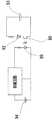
図を用いて説明する。図23は、特許文献1に示した従来技術を説明しやすいようにその主旨を逸脱しない程度に書き直した図である。100は電子腕時計本体、101はバンド、102はケーシング、103は電源部、104はスイッチ手段、105は電池、106はEL素子である。 This will be described with reference to the drawings. FIG. 23 is a diagram rewritten to the extent that it does not depart from the gist of the prior art disclosed in
特許文献1に示した従来技術は、電子腕時計本体100に接続しているバンド101にEL素子106を設け、このEL素子106が発光するものである。透明または半透明の樹脂部材で構成されるバンド101に設置されたEL素子106に対して、バンド101に設けたケーシング102内部に設置された電池105から電力を供給する。 In the prior art disclosed in
電源部103では、電池105からの電力供給を制御することによって、EL素子106への給電方法を定常的、間欠的、過渡的など変化させて、所定の発光パターンを生成する。また、電源部103には図示しない振動センサを設置し、使用者の動きをトリガにして発光を行うこともできる。ケーシング102に設置されたスイッチ手段104を操作す
ることによって、図示しない振動センサのセンシングを有効または無効に切り替えることもできる。In the
特許文献2に示した従来技術は、電子腕時計の文字盤とバンドとにEL素子を備えている。図を用いて説明する。図24は、特許文献2に示した従来技術を説明しやすいようにその主旨を逸脱しない程度に書き直した図である。 The prior art disclosed in
200は電子腕時計本体、201は文字盤、202はバンド、203はフレキシブルパネル、204はスイッチ手段、291〜298はEL素子である。EL素子291〜298は個々が所定の絵柄(例えば、イルカ)が表示できるようになっており、通電することにより発光し、文字盤201の背面およびフレキシブルパネル203上に配置されている。 200 is an electronic wristwatch body, 201 is a dial, 202 is a band, 203 is a flexible panel, 204 is switch means, and 291 to 298 are EL elements. Each of the
また、フレキシブルパネル203はバンド202内部に配置されている。バンド202は、EL素子291〜298の発光を外部から視認できるように、透光性をもつ部材により構成されている。文字盤201は、EL素子294,295が、外部から視認することができるように開口している。 The
フレキシブルパネル203は、電子腕時計本体200の図示しない開口部を通り、電子腕時計本体200内部に配置された図示しない制御部と電気的に接続されている。この制御部は、EL素子291〜298を所定のパターンで発光制御し、例えば、イルカの絵柄がバンド202上を移動したり、バンド202から文字盤201に移動したりといった演出効果をもたらす。 The
また、スイッチ手段204は、それ自身が発光開始のトリガとなったり、あるいは発光開始のトリガとなる図示しない振動センサや角度センサを有効化または無効化する手段となるのである。 Further, the switch means 204 is a means for enabling or disabling a vibration sensor or an angle sensor (not shown) that itself triggers light emission or triggers light emission.
このような構成とすることによって、文字盤とバンドとが一体に発光するように見え、遊び心と夜間歩行時の視認性が向上する旨の記載がある。
一般に、人間が活動するときに必要な所謂エネルギー源は、たんぱく質,糖質,脂質の3つであるといわれている。この3つは常に均等にエネルギーに変換されるのではなく、人間の活動状況に応じて順番がある。There is a description that, by adopting such a configuration, the dial and the band appear to emit light integrally, and playability and visibility at night walking are improved.
In general, it is said that there are three so-called energy sources necessary for human activities, namely protein, carbohydrate and lipid. These three are not always converted to energy evenly, but in order according to the human activity.
このうち、もっとも後に変換されるのがたんぱく質であって、たんぱく質は、糖質や脂質をエネルギーに変換しつくしたときに筋肉などを分解してエネルギーとするものである。従って、通常の生活や運動状態においては、そのエネルギー源は、糖質と脂質との2つを考えればよい。 Among these, the protein that is converted most recently is protein, which breaks down muscles and the like into energy when sugars and lipids are completely converted into energy. Therefore, in normal life and exercise state, the energy source may be two, carbohydrate and lipid.
糖質と脂質とは、運動強度によってその使われ方が異なっている。運動強度が上がるほど肝臓や筋肉に蓄積している糖質をエネルギー源とし、その逆の低い運動強度においては脂質をエネルギー源としている。また、エネルギーは、エネルギー源を酸素によって分解する有酸素性代謝と、酸素を使わない無酸素性代謝とから得られる。 Carbohydrates and lipids are used differently depending on exercise intensity. As the exercise intensity increases, carbohydrates accumulated in the liver and muscles are used as energy sources, and vice versa, lipids are used as energy sources. Energy is obtained from aerobic metabolism in which an energy source is decomposed by oxygen and anaerobic metabolism without using oxygen.
無酸素性代謝で得られるエネルギーは、瞬発力を必要とするような運動に利用されるが、40秒程度の全力運動でエネルギー源を使い切るほどに少なく、長時間の運動では無視することができる。このため、長時間運動時のエネルギー消費量は、酸素摂取量と概ね比例する。 The energy obtained by anaerobic metabolism is used for exercise that requires instantaneous force, but it is so small that the energy source is used up for about 40 seconds, and can be ignored for long-term exercise. . For this reason, the energy consumption during long exercise is generally proportional to the oxygen intake.
運動強度とは、運動の強さや身体にかかる負荷を指し示す指標で、最大酸素摂取量を1
00%としてその何%で運動するかを示す。その数値が大きいほどエネルギー消費量が増え、すなわち、身体にかかる負荷が大きくなると言い換えられる。Exercise intensity is an index that indicates the intensity of exercise and the load on the body. The maximum oxygen intake is 1
00% indicates the percentage of exercise. In other words, the larger the value, the greater the energy consumption, that is, the greater the load on the body.
運動強度は、行う運動やその種別によってその数値が特定されているものではなく、また、同じ運動を行ったとしても個人によってその数値は異なり、その数値を正確に知るには運動中の酸素摂取量を計測する必要がある。 The value of exercise intensity is not specified by the type of exercise to be performed or its type, and even if the same exercise is performed, the value varies depending on the individual, and in order to know the value accurately, oxygen intake during exercise It is necessary to measure the amount.
しかし、そのために大掛かりな装置と専門的な知識とが必要で、一般にその数値を知ることは難しい。そこで近年では、酸素摂取量と概ね比例する心臓の心拍数を基に数値化されることが多い。すなわち、身体にかかる負荷を心拍数をもって把握するのである。 However, this requires a large-scale device and specialized knowledge, and it is generally difficult to know the numerical values. Therefore, in recent years, it is often quantified based on the heart rate of the heart which is roughly proportional to the oxygen intake. That is, the load on the body is grasped from the heart rate.
心拍数とは、一定期間の間に得られる心拍の数のことであるが、一般には、理解しやすいように1分間の心拍の数として表す場合が多い。
すでに述べたとおり、低い運動強度の運動時は脂質がエネルギー源となり、高い運動強度の運動時には糖質がエネルギー源となる。昨今これらを鑑みて、糖質と脂質とのどちらを利用してエネルギー源とするかが多く議論されており、この考え方を身体の筋力アップやダイエット、生活習慣病の予防などに適用しようという提案も多い。The heart rate is the number of heart beats obtained during a certain period, but in general, it is often expressed as the number of heart beats per minute for easy understanding.
As already mentioned, lipids serve as energy sources during exercise with low exercise intensity, and carbohydrates serve as energy sources during exercise with high exercise intensity. In recent years, there are many discussions on whether to use carbohydrates or lipids as an energy source. Proposal to apply this concept to physical strength improvement, diet, prevention of lifestyle-related diseases, etc. There are many.
さらに近年では、運動強度を運動トレーニングに用いることも行われている。例えば、持久力や基礎体力向上には運動強度70〜80%程度、生活習慣病予防には運動強度40〜60%程度を維持するように運動トレーニングを行うと良いとされる報告もある。 Furthermore, in recent years, exercise intensity is also used for exercise training. For example, there are reports that exercise training should be performed so as to maintain an exercise intensity of about 70 to 80% for improving endurance and basic physical strength, and an exercise intensity of about 40 to 60% for preventing lifestyle-related diseases.
このような事情から、運動トレーニングにおいて、過不足のない運動トレーニングを実現する方法の1つとして、運動強度から算出される心拍数を運動トレーニング指標として用い、運動量を調整する方法が知られている。すなわち、目標運動強度を設定し、これを目標心拍数で管理するのである。 Under such circumstances, as a method for realizing exercise training without excess or deficiency in exercise training, a method of adjusting the amount of exercise using a heart rate calculated from exercise intensity as an exercise training index is known. . That is, the target exercise intensity is set and managed by the target heart rate.
目標運動強度とは、これから運動トレーニングなどを行おうとするときに目標とする運動強度であって、それに相当する心拍数を目標心拍数という。目標心拍数は、次の式より数値化される。 The target exercise intensity is an exercise intensity targeted when exercise training or the like is to be performed from now on, and a heart rate corresponding to the exercise intensity is called a target heart rate. The target heart rate is quantified by the following formula.
目標心拍数=(最大心拍数−安静時心拍数)×目標運動強度+安静時心拍数
また、最大心拍数の計測は難しいが、一般に加齢と共にその値は低下することから、次の式により置き換え可能なことが知られている。Target heart rate = (Maximum heart rate-Resting heart rate) x Target exercise intensity + Resting heart rate Although it is difficult to measure the maximum heart rate, the value generally decreases with age. It is known that it can be replaced.
最大心拍数=220−年齢
先にも述べたが、運動強度は、行う運動ごとに正確にその値が特定されているわけではないが、運動の種別と運動強度との間には、おおよそ次のような関係があることが知られている。例えば、短距離を全力疾走する程度の運動のときは運動強度90%、ジョギングをする程度のときは運動強度60%、ウォーキングをする程度のときは運動強度40%などである。Maximum heart rate = 220-age As mentioned earlier, the value of exercise intensity is not accurately specified for each exercise to be performed. It is known that there is such a relationship. For example, the exercise intensity is 90% when exercising at a short distance, the exercise intensity is 60% when jogging, and the exercise intensity is 40% when walking.
上述の目標心拍数の算出においては、このような運動の種別と運動強度との関係を鑑みて運動強度の数値を入力する場合も多く、例えば、40歳の人がジョギング程度の運動を想定した場合の目標心拍数は、100〜120程度であると知りえることができる。 In the calculation of the target heart rate described above, in many cases, a numerical value of exercise intensity is input in consideration of the relationship between the type of exercise and the exercise intensity. For example, a 40-year-old person assumed an exercise of jogging degree. In this case, it can be known that the target heart rate is about 100 to 120.
心拍数の測定にあっては、指を手首の内側や首に当てて、皮膚が心臓の鼓動に応じて振動する様子をその指で感じることをもって測ることができるが、目標心拍数を自分なりに設定して心拍数を運動トレーニング指標とすることが盛んに行われるようになってくると、運動中やトレーニング直後であっても心拍数を測りたいという要望があり、そのような
状況にあっても簡便に心拍数を測定できる心拍計が求められるようになってきた。このような事情から、近年、多くの電子心拍計の提案がなされている。You can measure your heart rate by placing your finger on the inside or neck of your wrist and feeling the skin vibrating with the heartbeat. When heart rate is set to be used as an exercise training index, there is a demand for measuring heart rate even during exercise or immediately after training. However, a heart rate monitor that can easily measure the heart rate has been demanded. In recent years, many electronic heart rate monitors have been proposed.
このような電子心拍計にあっては、一般に心電位検出方式が広く知られている。例えば、指や胸部に脈波を検出する電極を持ったベルト状の脈波検出部を装着し、これとは独立した表示部に有線または無線で情報を送信し、表示するものである。 In such an electronic heart rate monitor, a cardiac potential detection method is generally widely known. For example, a belt-like pulse wave detection unit having an electrode for detecting a pulse wave is attached to a finger or a chest, and information is transmitted and displayed on a display unit independent of this by wire or wireless.
表示部は、腕などに装着して脈波検出部が検出した脈波の周期から心拍数を求めて表示する。もちろん、脈波検出部と表示部を一体化したものもある。
脈波検出部には、電極を用いた電極式のほかに血流の変化を光で捕らえる光学式や血圧の変化を圧力で捉える圧力式などもある。The display unit obtains and displays the heart rate from the cycle of the pulse wave detected by the pulse wave detection unit attached to the arm or the like. Of course, there is also an integrated pulse wave detection unit and display unit.
In addition to the electrode type using electrodes, the pulse wave detection unit includes an optical type that captures changes in blood flow with light and a pressure type that captures changes in blood pressure with pressure.
もちろん、使用者情報である年齢や安静時心拍数や最大心拍数や目標運動強度などを簡単に心拍計に設定できる装置も多くの提案を見るものであり、幅を持った目標心拍数を算出したり、計測中の心拍数と使用者情報とを比較して得られる結果を運動トレーニング指標として文字や絵や音で報知したりするものもある(例えば、特許文献3(特開平9−75491号公報)参照。)。 Of course, there are many proposals for devices that can easily set user information such as age, resting heart rate, maximum heart rate, and target exercise intensity in the heart rate monitor, and calculate the target heart rate with a wide range. Or the result obtained by comparing the heart rate being measured and the user information is reported as an exercise training index with characters, pictures or sounds (for example, Japanese Patent Laid-Open No. 9-75491). No.))).
特許文献3に示した従来技術を説明する。図25は特許文献3に示した従来技術をその主旨を逸脱しない程度に書き直した図である。図25において、299は使用者、300は装置本体、301はケーブル、302はセンサユニット、303はリストバンド、308は液晶表示装置、311a〜311gはスイッチである。 The prior art shown in
装置本体300は、リストバンド303によって使用者299の腕に装着されている。この装置本体300には、センサユニット302がケーブル301で接続されており、このセンサユニット302は、使用者299の指に装着されている。 The apparatus main body 300 is attached to the arm of the
このセンサユニット302によって検出される脈波を装置本体300で信号処理することで心拍数を求め、スイッチ311a〜311gから入力される使用者情報を基に演算し、得られた運動トレーニング指標や心拍数などの報知情報を報知する。報知は、液晶表示装置308による表示や図示しない発音手段によるアラーム音などにより行われる。 A pulse rate detected by the
このように、特許文献3に示した従来技術は、運動トレーニング指標を文字や音で報知することができる。心拍を計測できる装置本体300を装着した状態で運動することにより、その運動が運動トレーニング指標となる目標心拍数に在るか否かをリアルタイムに知ることができる。使用者は、これらの報知情報を利用して運動量を調整することができる。 As described above, the prior art disclosed in
また、使用者が運動に夢中になり過度の運動に陥ったり、体調が平常時から逸脱したりといった所謂オーバートレーニングの防止などにも用いることができる。
特許文献1と特許文献2とに示した従来技術は、電子腕時計のバンドが発光することで視認性などは向上するが、電子腕時計としては、使い勝手が悪いという問題があった。
すなわち、特許文献1と特許文献2とに示した従来技術は、電子腕時計のバンドにEL素子などの発光体を組み込む必要があって、従来知られている電子腕時計のバンドと比較
してバンドの構造が複雑になり、バンド自体の可撓性も悪化することにより、電子腕時計においては非常に重要な腕とのフィット感や装着感が悪化してしまうという問題があった。Although the prior arts shown in
That is, in the conventional techniques shown in
さらに、通常必要となるバンドの長さ調節ができないといったメンテナンス上の問題もあった。
また、電子腕時計の製造工程も複雑になるため、製造コストが増加してしまうという問題もあった。In addition, there is a maintenance problem that the band length that is normally required cannot be adjusted.
In addition, since the manufacturing process of the electronic wrist watch is complicated, there is a problem that the manufacturing cost increases.
さらにまた、電子腕時計の文字盤などの表示装置だけを発光させる場合に較べてバンド自体の発光面積が大きくなるため、発光体が消費する電力も大きくなり、電子腕時計に搭載する電池など電源手段の消耗によって、電子腕時計の稼働時間が短くなってしまうという問題があった。 Furthermore, since the light emitting area of the band itself is larger than when only the display device such as the dial of the electronic wristwatch emits light, the power consumed by the light emitter is also increased, and the power supply means such as a battery mounted on the electronic wristwatch is increased. There is a problem that the operating time of the electronic wristwatch is shortened due to wear.
この問題は、電源手段の大型化で改善するが、近年の小型軽量化の傾向がある電子腕時計への要求に逆行するため好ましくないばかりか、大型化した電源手段は、電子腕時計のデザインも制限してしまうという新たな問題も生じてしまう。 This problem can be improved by increasing the size of the power supply means, but it is not preferable because it goes against the recent demand for electronic watches that tend to be smaller and lighter. A new problem will occur.
従って、バンドの発光による視認性やファッション性の向上と電子腕時計としての装着感や十分な稼働時間などとを両立する電子腕時計は、いまだ提案されていないのが実情である。 Therefore, in reality, no electronic wristwatch has yet been proposed that achieves both improved visibility and fashionability due to light emission of the band and a feeling of wearing as an electronic wristwatch and sufficient operating time.
また、上記のような電子腕時計だけではなく、例えば、腕に装着するタイプの携帯電話などの多機能を併せ持つ装着型電子機器の開発が盛んになっているが、このような電子機器において、例えば、着信音などの音声による報知だけでなく、上記のようにバンド、電子機器本体の発光による報知があれば、確実に使用者に情報を報知することができ、極めて便利である。 In addition to the electronic wristwatch as described above, for example, the development of wearable electronic devices having multiple functions such as a mobile phone of the type worn on the wrist has been actively developed. In addition to notifying by sound such as a ring tone, if there is notifying by light emission of the band or the electronic device main body as described above, it is possible to reliably notify the user of information, which is extremely convenient.
本発明の目的は、上記課題を解決しようとするもので、バンドの製造およびメンテナンスが容易で、かつデザインの制約が少なく、また、十分なバンドの発光効果を持ち、さらに、消費電力を少なくすることが可能な装着型電子機器を提供することにある。 An object of the present invention is to solve the above-mentioned problems, and it is easy to manufacture and maintain a band, has few design restrictions, has a sufficient band light emitting effect, and further reduces power consumption. An object of the present invention is to provide a wearable electronic device that can perform the above-described operation.
近年では、夜間に運動トレーニングを行う場合も増え、暗い所で心拍計を活用することも増えている。しかしながら、特許文献3に示した従来技術は、液晶表示装置308にバックライトが用意されているものの、運動中、特に腕が揺れたり、眼球が上下動したりするような運動を行う場合にあっては、その液晶表示装置308自体が小さいために、運動トレーニング指標などの報知情報を瞬時に把握することができないという問題があった。 In recent years, the number of exercise training at night has increased, and the use of heart rate monitors in dark places has also increased. However, the conventional technique disclosed in
特に、液晶表示装置308が手の甲側にあるために腕をひねって見る必要もあり、例えば、ランニング中においては不自然なフォームを強いられることによりランニングフォームが乱れたりすることで、正常な運動トレーニングを妨げていた。 In particular, since the liquid
また、野外での使用においては、音による報知も公道を走る自動車などの騒音により聞き漏らす場合が少なくなかった。
すなわち、特許文献3に示す従来技術は、運動トレーニングに関わる報知情報が使用者に充分報知しきれないという問題があり、運動中に使用するという前提から、このような問題は大きな問題となっていた。In addition, when used outdoors, it is often the case that sound notifications are missed by the noise of automobiles running on public roads.
That is, the conventional technique shown in
本発明のもう1つの目的は、上記課題を解決しようとするもので、激しい運動中であっても、騒音がある環境下であっても、自然な運動フォームを維持したままにトレーニング
指標を容易に認識することが可能な生体測定装置を提供することにある。Another object of the present invention is to solve the above-mentioned problems. Even during intense exercise or in a noisy environment, the training index can be easily maintained while maintaining a natural exercise form. An object of the present invention is to provide a biometric apparatus that can be recognized by the user.
本発明は、前述したような従来技術における課題及び目的を達成するために発明されたものであって、本発明の装着型電子機器は、
装着型電子機器を発光させる発光手段を備える装着型電子機器であって、
前記発光手段が、所定の波長の光を発する発光素子と、該発光素子が発する光を所定の方向に導光する導光手段とを備え、
前記発光素子が、装着型電子機器の本体に備えられるとともに、装着型電子機器の制御に基づいて発光が制御されるように構成され、
前記導光手段が、装着型電子機器の本体に備えられた本体側導光手段、バンドに備えられたバンド側導光手段のうち少なくとも1つの導光手段を備え、
前記本体側導光手段が、装着型電子機器の本体の表面に所定の面を向けて配置されるとともに、
前記発光素子からの光が、本体側導光手段を介して、装着型電子機器の本体の表面から放出されるように構成されているか、または、
前記バンド側導光手段が、バンドの表面に所定の面を向けて配置されるとともに、
前記発光素子からの光が、バンド側導光手段を介して、バンド表面から放出されるように構成されていることを特徴とする。The present invention has been invented in order to achieve the above-described problems and objects in the prior art.
A wearable electronic device comprising light emitting means for emitting light from the wearable electronic device,
The light emitting means includes a light emitting element that emits light of a predetermined wavelength, and a light guide means that guides light emitted from the light emitting element in a predetermined direction,
The light emitting element is provided in the body of the wearable electronic device, and configured to control light emission based on the control of the wearable electronic device,
The light guide means includes at least one light guide means of a main body side light guide means provided in a main body of the wearable electronic device and a band side light guide means provided in a band,
The body side light guide means is disposed with a predetermined surface facing the surface of the body of the wearable electronic device,
The light from the light emitting element is configured to be emitted from the surface of the main body of the wearable electronic device via the main body side light guide means, or
The band side light guide means is disposed with a predetermined surface facing the surface of the band,
The light from the light emitting element is configured to be emitted from the band surface through the band side light guide means.
また、本発明の装着型電子機器は、前記導光手段が、装着型電子機器の本体に備えられた本体側導光手段と、バンドに備えられたバンド側導光手段とを備え、
前記発光素子から発せられた光が、本体側導光手段を介して、バンド側導光手段に導光されて、バンド側導光手段を介して、バンドの表面から放出されるように構成されていることを特徴とする。Further, in the wearable electronic device of the present invention, the light guide means includes a main body side light guide means provided in the main body of the wearable electronic device, and a band side light guide means provided in the band,
The light emitted from the light emitting element is guided to the band side light guide means via the main body side light guide means, and is emitted from the surface of the band via the band side light guide means. It is characterized by.
また、本発明の装着型電子機器は、前記導光手段が、装着型電子機器の本体に備えられた本体側導光手段と、バンドに備えられたバンド側導光手段とを備え、
前記発光素子からの光が、本体側導光手段を介して、装着型電子機器の本体の表面から放出されるように構成されているとともに、
前記発光素子から発せられた光が、本体側導光手段を介して、バンド側導光手段に導光されて、バンド側導光手段を介して、バンドの表面から放出されるように構成されていることを特徴とする。Further, in the wearable electronic device of the present invention, the light guide means includes a main body side light guide means provided in the main body of the wearable electronic device, and a band side light guide means provided in the band,
The light from the light emitting element is configured to be emitted from the surface of the main body of the wearable electronic device through the main body side light guide means,
The light emitted from the light emitting element is guided to the band side light guide means via the main body side light guide means, and is emitted from the surface of the band via the band side light guide means. It is characterized by.
このように構成することによって、装着型電子機器の本体に備えられた発光素子が発する光が、導光手段に導かれ、本体側導光手段を介して、装着型電子機器の本体の表面から放出されるか、または、バンド側導光手段を介して、バンド表面から放出されるか、あるいは、これらの装着型電子機器の本体の表面、バンド表面の両方から放出されるようになっている。 With this configuration, light emitted from the light emitting element provided in the main body of the wearable electronic device is guided to the light guide means, and from the surface of the main body of the wearable electronic device via the main body side light guide means. It is emitted from the surface of the band via the band side light guiding means, or from both the surface of the main body of the wearable electronic device and the surface of the band. .
従って、装着型電子機器の本体の一部またはバンドを発光させることができる。これにより、本発明の装着型電子機器は、バンドの発光に際して、バンド自体に発光する手段を搭載していなくても、あたかもバンド自体が発光するように見えるものである。 Therefore, a part or band of the main body of the wearable electronic device can be made to emit light. As a result, the wearable electronic device of the present invention appears as if the band itself emits light even when the band itself is not equipped with means for emitting light.
また、導光手段の形状などにより、バンドを所定の状態に発光させることができるか
ら、バンドの発光面積を大きくしても、装着型電子機器としての消費電力が増加することはないものである。Further, since the band can emit light in a predetermined state depending on the shape of the light guide means, etc., even if the light emission area of the band is increased, the power consumption as the wearable electronic device does not increase. .
また、このような構成とすることにより、バンドの構造を複雑にすることなくバンドの発光による視認性やファッション性の向上と電子腕時計としての装着感や十分な稼働時間
などとを両立する、例えば、電子腕時計などの装着型電子機器を構成することができる。In addition, by adopting such a configuration, without complicating the structure of the band, it is possible to achieve both improvement in visibility and fashionability due to light emission of the band and a feeling of wearing as an electronic watch, sufficient operation time, etc. A wearable electronic device such as an electronic wristwatch can be configured.
従って、例えば、腕に装着するタイプの携帯電話などの多機能を併せ持つ装着型電子機器の開発が盛んになっているが、このような電子機器において、例えば、着信音などの音声による報知だけでなく、上記のようにバンド、電子機器本体またはバンドの発光による報知が可能であるので、確実に使用者に情報を報知することができ、極めて便利である。 Accordingly, for example, wearable electronic devices that have multiple functions such as a mobile phone that is worn on the wrist have been actively developed. However, in such electronic devices, for example, only notification by sound such as a ringtone is possible. In addition, since notification by light emission of the band, the electronic device main body or the band is possible as described above, information can be reliably notified to the user, which is extremely convenient.
また、本発明の装着型電子機器は、前記バンド側導光手段が、バンドの表面または内部に備えられていることを特徴とする。
このようにバンド側導光手段が、バンドの表面または内部に備えられていることによって、装着型電子機器の本体に備えられた発光素子が発する光が、バンドの表面または内部を介して導光されて、バンドの表面から確実に放出されるとともに、バンドの構造を複雑にすることなく、バンドの発光による視認性やファッション性の向上を図ることができる。The wearable electronic device of the present invention is characterized in that the band-side light guide means is provided on the surface or inside of the band.
Since the band-side light guide means is provided on the surface or inside of the band as described above, the light emitted from the light emitting element provided on the body of the wearable electronic device is guided through the surface or inside of the band. As a result, it can be surely emitted from the surface of the band, and the visibility and fashionability by the emission of the band can be improved without complicating the structure of the band.
また、本発明の装着型電子機器は、前記発光素子が、装着型電子機器の本体に複数個設けられ、それぞれの発光素子に対応して、複数個のバンド側導光手段がバンドに備えられていることを特徴とする。 In the wearable electronic device of the present invention, a plurality of the light emitting elements are provided in the body of the wearable electronic device, and a plurality of band-side light guides are provided in the band corresponding to each light emitting element. It is characterized by.
このように発光素子が、装着型電子機器の本体に複数個設けられ、それぞれの発光素子に対応して、複数個のバンド側導光手段がバンドに備えられていることによって、発光素子が発する光をより多くバンドに伝達し、バンドをより鮮明に発光させることができる。また、発光箇所を自由に選択できることから、発光箇所やその模様を自由に演出することができる。 As described above, a plurality of light emitting elements are provided in the main body of the wearable electronic device, and a plurality of band-side light guides are provided in the band corresponding to each light emitting element, whereby the light emitting element emits light. More light can be transmitted to the band, and the band can be emitted more clearly. Moreover, since the light emission location can be freely selected, the light emission location and the pattern can be freely produced.
また、本発明の装着型電子機器は、前記バンド側導光手段が、装着型電子機器の本体から離間するにつれて漸次その幅が小さくなるように形成されていることを特徴とする。
このように構成することによって、本発明の装着型電子機器を腕に装着した際、バンドの6時方向が使用者側となるから、バンド側導光手段の幅を使用者の目につく部分を広くすることで、発光素子の発光輝度が同一であっても見かけ上明るく感じるようになるのである。従って、発光素子に印加する駆動電力を低減しても、使用者が感じるバンドの発光状態は、さほど暗くならないので、発光素子の駆動に伴う消費電力を低減することができる。The wearable electronic device according to the present invention is characterized in that the band-side light guide means is formed so that the width thereof gradually decreases as the distance from the main body of the wearable electronic device increases.
With this configuration, when the wearable electronic device of the present invention is worn on the arm, the 6 o'clock direction of the band is on the user side. By widening, it seems that even if the light emitting luminance of the light emitting element is the same, it appears to be bright. Therefore, even if the driving power applied to the light emitting element is reduced, the light emission state of the band felt by the user is not so dark, so that power consumption associated with driving the light emitting element can be reduced.
また、本発明の装着型電子機器は、前記バンドの表面に遮光性の指標部が形成されていることを特徴とする。
このように構成することによって、バンドの表面に形成した遮光性の指標部を、例えば、文字、記号、図形などの形状とすることによって、バンド側導光手段に光が入射すると、バンド表面の遮光性の指標部の周囲は発光するが、遮光性の指標部の下からの光は遮光されるので、遮光性の指標部の形状が際立ち、バンドを所定の形状や模様にワンポイントで発光させることができ、高い装飾効果を得ることができる。The wearable electronic device according to the present invention is characterized in that a light-shielding index portion is formed on the surface of the band.
By configuring in this way, the light-shielding index portion formed on the surface of the band is formed into a shape such as a character, a symbol, a figure, etc. Light is emitted around the light-shielding index part, but light from below the light-shielding index part is shielded, so the shape of the light-shielding index part stands out and the band emits light at a single point in a predetermined shape or pattern And a high decorative effect can be obtained.
また、本発明の装着型電子機器は、前記バンドの表面が、遮光性であって、バンドの表面に指標開口部が形成されていることを特徴とする。
このようにバンドの表面が、遮光性であって、バンドの表面に指標開口部を形成することによって、この指標開口部から、バンド側導光手段の発光を視認できるようになっている。The wearable electronic device of the present invention is characterized in that the surface of the band is light-shielding and an index opening is formed on the surface of the band.
In this way, the surface of the band is light-shielding, and by forming the index opening on the surface of the band, the light emission of the band-side light guide means can be visually recognized from the index opening.
従って、指標開口部を、例えば、文字、記号、図形などの形状とすることによって、バンド側導光手段に光が入射すると、バンド表面の指標開口部は発光するが、その周囲の遮
光性の指標部の下からの光は遮光されるので、バンド表面の指標開口部の形状が際立ち、バンドを所定の形状や模様にワンポイントで発光させることができ、高い装飾効果を得ることができる。Therefore, by setting the index opening to a shape such as a character, symbol, figure, etc., when light is incident on the band side light guide means, the index opening on the surface of the band emits light, but the surrounding light shielding property is reduced. Since the light from under the index portion is shielded, the shape of the index opening on the surface of the band stands out, and the band can be made to emit light at a single point in a predetermined shape or pattern, so that a high decorative effect can be obtained.
また、本発明の装着型電子機器は、前記本体側導光手段側の表面に、遮光性の指標部が形成されていることを特徴とする。
このように構成することによって、本体側導光手段側の表面に形成した遮光性の指標部を、例えば、文字、記号、図形などの形状とすることによって、本体側導光手段に光が入射すると、本体側導光手段の表面の遮光性の指標部の周囲は発光するが、遮光性の指標部の下からの光は遮光されるので、遮光性の指標部の形状が際立ち、本体側導光手段の表面を所定の形状や模様にワンポイントで発光させることができ、高い装飾効果を得ることができる。The wearable electronic apparatus according to the present invention is characterized in that a light-shielding index portion is formed on the surface on the main body side light guide means side.
By configuring in this way, the light-shielding indicator portion formed on the surface on the main body side light guide means side has a shape such as a character, symbol, figure, etc., so that light is incident on the main body light guide means. Then, the area around the light-shielding index portion on the surface of the light guide means on the main body emits light, but the light from the bottom of the light-shielding index portion is shielded, so that the shape of the light-shielding index portion stands out and the main body side The surface of the light guide means can be made to emit light at a single point in a predetermined shape or pattern, and a high decorative effect can be obtained.
また、本発明の装着型電子機器は、前記本体側導光手段側の表面が、遮光性であって、本体側導光手段側の表面に指標開口部が形成されていることを特徴とする。
このように本体側導光手段側の表面が、遮光性であって、本体側導光手段側の表面に指標開口部を形成することによって、この指標開口部から、本体側導光手段の発光を視認できるようになっている。The wearable electronic device according to the present invention is characterized in that the surface on the main body side light guide means side is light-shielding and an index opening is formed on the surface on the main body side light guide means side. .
Thus, the surface on the main body side light guide means side is light-shielding, and by forming the index opening on the surface on the main body side light guide means side, the light emission of the main body side light guide means from this index opening. Can be visually recognized.
従って、指標開口部を、例えば、文字、記号、図形などの形状とすることによって、本体側導光手段に光が入射すると、本体側導光手段の表面の指標開口部は発光するが、その周囲の遮光性の指標部の下からの光は遮光されるので、本体側導光手段の表面の指標開口部の形状が際立ち、バンドを所定の形状や模様にワンポイントで発光させることができ、高い装飾効果を得ることができる。 Therefore, for example, when the indicator opening is formed into a shape such as a character, symbol, figure, etc., when light is incident on the main body-side light guide means, the indicator opening on the surface of the main body-side light guide means emits light. Since the light from under the surrounding light-shielding indicator part is shielded, the shape of the indicator opening on the surface of the light guide means on the body side stands out, and the band can be made to emit light at a single point in a predetermined shape or pattern High decorative effect can be obtained.
また、本発明の装着型電子機器は、前記導光手段の発光側表面に、前記発光素子からの光のうち、所定の波長の光のみを透過させるフィルターが配置されていることを特徴とする。 In the wearable electronic device according to the present invention, a filter that transmits only light having a predetermined wavelength out of light from the light emitting element is disposed on a light emitting side surface of the light guide unit. .
このように構成することによって、フィルターを介して、発光素子からの光のうち、所定の波長の光のみを透過させることができるので、使用者に所定の波長の光による情報の報知ができ、フィルターの形状、種類、配置位置を変更することによって、発光色、発光箇所を自由に選択できるので、発光箇所やその模様を自由に演出することができ、発光による視認性やファッション性の向上を図ることができる。 By configuring in this way, it is possible to transmit only light of a predetermined wavelength out of the light from the light emitting element through the filter, so that the user can be notified of information by the light of the predetermined wavelength, By changing the shape, type, and position of the filter, the light emission color and light emission location can be freely selected, so the light emission location and its pattern can be freely produced, improving the visibility and fashionability of the light emission. Can be planned.
また、本発明の装着型電子機器は、前記フィルターの表面に、前記発光素子からの光のうち、フィルターを透過した所定の波長の光により発光する指標部が形成されていることを特徴とする。 The wearable electronic device according to the present invention is characterized in that an index portion that emits light of a predetermined wavelength that has passed through the filter out of the light from the light emitting element is formed on the surface of the filter. .
このようにフィルターの表面に、前記発光素子からの光のうち、フィルターを透過した所定の波長の光により発光する指標部が形成されていれば、この指標部の形状、種類、配置位置を変更することによって、発光色、発光箇所を自由に選択できるので、発光箇所やその模様を自由に演出することができ、発光による視認性やファッション性の向上を図ることができる。 In this way, if an indicator portion that emits light of a predetermined wavelength that has passed through the filter out of the light from the light emitting element is formed on the surface of the filter, the shape, type, and position of the indicator portion are changed. By doing so, the light emission color and the light emission location can be freely selected, so that the light emission location and the pattern can be freely produced, and the visibility and fashionability by the light emission can be improved.
また、本発明の装着型電子機器は、前記発光素子が、LED発光素子、紫外線発光素子、電子線発光素子から選択した少なくとも1つの発光素子から構成されていることを特徴とする。 The wearable electronic device of the present invention is characterized in that the light emitting element is composed of at least one light emitting element selected from an LED light emitting element, an ultraviolet light emitting element, and an electron beam light emitting element.
このように発光素子を選択することによって、種々の所定の波長の光により、装着型電
子機器の本体の一部またはバンドを発光させることができ、発光による視認性やファッション性の向上を図ることができる。By selecting the light emitting element in this way, a part or band of the main body of the wearable electronic device can be emitted by light of various predetermined wavelengths, and visibility and fashionability are improved by light emission. Can do.
すなわち、例えば、発光素子が、LED発光素子の場合に、LED発光素子を、赤色(R)LED発光素子、緑色(G)LED発光素子、青色(B)LED発光素子の3色のLEDから構成し、フィルターR,G,BをこれらのLEDから発せられたR,G,Bのそれぞれの光のみを透過するフィルターとすれば、R,G,Bの発光箇所、形状などを選択することができ、発光による視認性やファッション性の向上を図ることができる。 That is, for example, when the light-emitting element is an LED light-emitting element, the LED light-emitting element is composed of three color LEDs, a red (R) LED light-emitting element, a green (G) LED light-emitting element, and a blue (B) LED light-emitting element. If the filters R, G, and B are filters that transmit only the R, G, and B light emitted from these LEDs, the light emission locations and shapes of the R, G, and B can be selected. It is possible to improve visibility and fashionability by light emission.
また、発光素子が、紫外線発光素子(UV−LED)、電子線発光素子である場合には、バンドパスフィルタを配置することによって、UV−LED、電子線発光素子から発せられた紫外線の波長、電子線の波長を選択して透過させ、紫外線、電子線により所定の色に発光する蛍光体を配置しておけば、発光箇所、形状などを選択することができ、発光による視認性やファッション性の向上を図ることができる。 In addition, when the light emitting element is an ultraviolet light emitting element (UV-LED) or an electron beam light emitting element, by arranging a band pass filter, the wavelength of the ultraviolet light emitted from the UV-LED or the electron beam light emitting element, By selecting the wavelength of the electron beam and transmitting it, and placing a phosphor that emits light in a predetermined color by ultraviolet light or electron beam, the light emission location, shape, etc. can be selected, and visibility and fashionability due to light emission Can be improved.
また、本発明の装着型電子機器は、前記バンド側導光手段が、光ファイバーから構成されていることを特徴とする。
このように構成することによって、装着型電子機器の本体に備えられた発光素子が発する光が、光ファイバーを介して確実に導光されて、バンドの表面から確実に放出されるとともに、バンドの構造を複雑にすることなく、バンドの発光による視認性やファッション性の向上を図ることができる。Moreover, the wearable electronic device of the present invention is characterized in that the band-side light guide means is composed of an optical fiber.
With this configuration, the light emitted from the light emitting element provided in the main body of the wearable electronic device is reliably guided through the optical fiber and is reliably emitted from the surface of the band, and the structure of the band. It is possible to improve visibility and fashionability due to light emission of the band without complicating.
また、本発明の装着型電子機器は、前記バンド側導光手段が、両面に回折格子を備えた導光部材から構成されていることを特徴とする。
このように構成することによって、装着型電子機器の本体に備えられた発光素子が発する光が、両面に回折格子を備えた導光部材によって、確実に導光されて、回折格子のスリットの隙間で回折されてバンド表面から確実に放出されるとともに、バンドの構造を複雑にすることなく、バンドの発光による視認性やファッション性の向上を図ることができる。The wearable electronic apparatus according to the present invention is characterized in that the band-side light guide means includes a light guide member having diffraction gratings on both sides.
With this configuration, the light emitted from the light emitting element provided in the main body of the wearable electronic device is reliably guided by the light guide member provided with the diffraction grating on both surfaces, and the gap between the slits of the diffraction grating. And is reliably emitted from the surface of the band, and visibility and fashionability due to light emission of the band can be improved without complicating the structure of the band.
また、本発明の装着型電子機器は、前記発光素子とバンド側導光手段との間に、液晶素子が配置され、
前記バンド側導光手段の表面に、相互に直交する偏向角を有する複数の指標偏向部材が設けられ、
前記液晶素子に印加する電圧を変化させることにより、複数の指標偏向部材を選択して散光させるように構成されていることを特徴とする。Further, in the wearable electronic device of the present invention, a liquid crystal element is disposed between the light emitting element and the band side light guide means,
A plurality of indicator deflection members having deflection angles orthogonal to each other are provided on the surface of the band side light guide means,
By changing the voltage applied to the liquid crystal element, a plurality of index deflecting members are selected and diffused.
このように構成することによって、装着型電子機器の本体に備えられた発光素子が発する光が、液晶素子を通過して、バンド側導光手段に導かれる。
そして、液晶素子に印加する電圧を変化させることにより、液晶素子を通過した光は所定の偏向角度を有しているので、この偏向角度に応じた偏向角を有する指標偏向部材から、バンド表面から光を放出させることができる。With this configuration, light emitted from the light emitting element provided in the body of the wearable electronic device passes through the liquid crystal element and is guided to the band-side light guide unit.
Then, by changing the voltage applied to the liquid crystal element, the light that has passed through the liquid crystal element has a predetermined deflection angle. From the index deflection member having the deflection angle corresponding to this deflection angle, from the band surface Light can be emitted.
従って、液晶素子に印加する電圧を変化させるだけで、発光箇所、形状などを選択することができ、発光による視認性やファッション性の向上を図ることができ、バンドの構造を複雑にすることなく、バンドの発光による視認性やファッション性の向上を図ることができる。 Therefore, by changing the voltage applied to the liquid crystal element, it is possible to select the light emission location, shape, etc., and to improve visibility and fashionability by light emission, without complicating the band structure. It is possible to improve visibility and fashionability due to light emission of the band.
また、本発明の装着型電子機器は、前記導光手段が、蓄光手段を備え、導光手段が導光する光を蓄光するように構成されていることを特徴とする。
また、本発明の装着型電子機器は、前記蓄光手段が、導光手段に隣接して備えられていることを特徴とする。The wearable electronic device of the present invention is characterized in that the light guide means includes a light storage means, and is configured to store light guided by the light guide means.
The wearable electronic device of the present invention is characterized in that the light storage means is provided adjacent to the light guide means.
また、本発明の装着型電子機器は、前記蓄光手段を備えた導光手段が、バンド側導光手段であることを特徴とする。
このように蓄光手段による光の吸収、発光を利用して、制御手段によって発光素子を所定の時間間隔で間欠駆動すると、発光素子が発光していない期間も蓄光手段が発光を継続するので、装着型電子機器の本体またはバンドの発光を維持することができる。The wearable electronic device according to the present invention is characterized in that the light guide means provided with the light storage means is a band-side light guide means.
As described above, when the light emitting element is intermittently driven by the control means at a predetermined time interval by utilizing the light absorption and light emission by the light storing means, the light storing means continues to emit light even when the light emitting element is not emitting light. The light emission of the main body or band of the electronic device can be maintained.
従って、非常に少ない消費電力で、装着型電子機器の本体またはバンドを長時間に渡って連続的に発光させることが可能となる。
また、前述のいずれか1つに記載の装着型電子機器を用いた使用者の生体情報を測定する生体測定装置であって、
前記発光素子からの光が、装着型電子機器の本体に備えられた本体側導光手段、バンドに備えられたバンド側導光手段のうち少なくとも1つの導光手段を介して、
装着型電子機器の本体の表面、バンドの表面からの少なくとも1つの表面から放出されることによって、生体情報を報知するように構成されていることを特徴とする。Therefore, the main body or band of the wearable electronic device can be continuously emitted for a long time with very little power consumption.
A biometric apparatus for measuring biometric information of a user using the wearable electronic device according to any one of the above,
The light from the light emitting element is transmitted through at least one light guide means of a main body side light guide means provided in the main body of the wearable electronic device and a band side light guide means provided in the band.
It is configured to notify biological information by being emitted from at least one surface from the surface of the main body of the wearable electronic device and the surface of the band.
このように構成することによって、装着型電子機器の本体に備えられた発光素子が発する光が、導光手段に導かれ、本体側導光手段を介して、装着型電子機器の本体の表面から放出されるか、または、バンド側導光手段を介して、バンド表面から放出されるか、あるいは、これらの装着型電子機器の本体の表面、バンド表面の両方から放出されることになり、例えば、心拍数、体温などの生体情報を確実に報知することができる。 With this configuration, light emitted from the light emitting element provided in the main body of the wearable electronic device is guided to the light guide means, and from the surface of the main body of the wearable electronic device via the main body side light guide means. Emitted from the band surface via the band-side light guiding means, or from both the surface of the wearable electronic device body and the band surface, for example, Biological information such as heart rate and body temperature can be reliably notified.
また、本発明の生体測定装置は、前記生体測定装置が、前記使用者の生体情報を検出し、該生体情報から所定の生体情報値を算出する生体情報値算出手段と、
前記使用者の使用者情報を入力する使用者情報入力手段と、
前記使用者情報と生体情報値とを比較する比較演算手段と、
前記比較演算手段の比較結果に応じて支援情報を報知する報知手段とを備え、
前記報知手段が、発光素子からの光が、装着型電子機器の本体に備えられた本体側導光手段、バンドに備えられたバンド側導光手段のうち少なくとも1つの導光手段を介して、
装着型電子機器の本体の表面、バンドの表面からの少なくとも1つの表面から放出されることによって、支援情報を報知する第1の報知手段を備えることを特徴とする。Further, the biometric device of the present invention is a biometric information value calculating means for detecting the biometric information of the user and calculating a predetermined biometric information value from the biometric information.
User information input means for inputting the user information of the user;
Comparison operation means for comparing the user information and the biological information value;
Informing means for informing support information according to the comparison result of the comparison operation means,
The notifying means is configured such that the light from the light emitting element is transmitted through at least one light guide means of a main body side light guide means provided in the main body of the wearable electronic device and a band side light guide means provided in the band.
It is provided with the 1st alerting | reporting means which alert | reports assistance information by being discharge | released from at least 1 surface from the surface of the main body of a wearable electronic device, and the surface of a band.
このように構成することによって、生体情報値算出手段によって、使用者の生体情報を検出して、生体情報値を求めるとともに、使用者情報入力手段を介して、使用者があらかじめ入力した使用者情報と生体情報値とを比較演算手段によって比較し、この比較演算手段の比較結果に応じて報知手段により、支援情報を報知するようになっている。 With this configuration, the biometric information value calculating unit detects the biometric information of the user to obtain the biometric information value, and the user information input by the user in advance via the user information input unit. And the biometric information value are compared by the comparison calculation means, and the support information is notified by the notification means according to the comparison result of the comparison calculation means.
そして、報知手段が、装着型電子機器の本体に備えられた発光素子が発する光が、導光手段に導かれ、本体側導光手段を介して、装着型電子機器の本体の表面から放出されるか、または、バンド側導光手段を介して、バンド表面から放出されるか、あるいは、これらの装着型電子機器の本体の表面、バンド表面の両方から放出されることになり、例えば、目標心拍数や任意の心拍数との関係を示すトレーニング指標や心拍情報などの支援情報を確実に報知することができる。 Then, the notification means causes the light emitted from the light emitting element provided in the main body of the wearable electronic device to be guided to the light guide means and emitted from the surface of the main body of the wearable electronic device via the main body side light guide means. Or is emitted from the band surface via the band-side light guide means or from both the surface of the body of the wearable electronic device and the band surface, for example, the target Support information such as a training index indicating a relationship with a heart rate or an arbitrary heart rate and heart rate information can be reliably notified.
また、本発明の生体測定装置は、前記報知手段が、文字または絵文字を用いて支援情報を報知する第2の報知手段をさらに備えることを特徴とする。
このように構成することによって、報知手段は、発光による第1の報知手段と、文字や絵文字による第2の報知手段とから構成されるので、第1の報知手段によって、発光を行
うことでいち早く使用者に報知情報があることを伝えることができるとともに、この第2の報知手段によって、使用者に対して詳細に報知情報を報知することができる。The biometric apparatus of the present invention is characterized in that the notification means further includes a second notification means for notifying support information using a character or a pictograph.
By configuring in this way, the notification means is composed of the first notification means by light emission and the second notification means by characters or pictograms, so that the first notification means promptly emits light. The user can be notified that the notification information is present, and the second notification means can notify the user of the notification information in detail.
また、発光は、発光箇所,発光条件,発光パターンのいずれかまたはその組み合わせで行うことができるため、視認性と表現の多様性が向上する。
このように、第1の報知手段と第2の報知手段との報知の役割を変えることで、使用者に適切に報知情報を伝達することができる。Further, since light emission can be performed at any one of light emission locations, light emission conditions, and light emission patterns, or a combination thereof, visibility and diversity of expression are improved.
Thus, the notification information can be appropriately transmitted to the user by changing the roles of notification between the first notification means and the second notification means.
また、本発明の生体測定装置は、前記生体測定装置が、運動トレーニングを行う使用者へ助言を与える機能を有する身体装着型運動トレーニング支援装置であって、
前記生体情報値算出手段が、使用者の生体情報を検出し、該生体情報から心拍数を算出する心拍数算出手段を備え、
前記比較演算手段が、使用者情報と心拍数とを比較する心拍数比較演算手段を備え、
前記報知手段が、心拍数比較演算手段の比較結果に応じて支援情報を報知する心拍数報知手段を備えることを特徴とする。The biometric device of the present invention is a body-worn exercise training support device having a function in which the biometric device gives advice to a user who performs exercise training,
The biological information value calculating means includes heart rate calculating means for detecting a user's biological information and calculating a heart rate from the biological information;
The comparison calculation means includes heart rate comparison calculation means for comparing user information and heart rate,
The notifying means includes a heart rate notifying means for notifying support information according to a comparison result of the heart rate comparison calculating means.
このように構成することによって、使用者の生体情報である脈波を検出して、心拍数を求めると共に、使用者があらかじめ入力した使用者情報である目標運動強度から算出される目標心拍数や任意の心拍数との関係を示すトレーニング指標や心拍情報を報知するようにしたもので、身体装着型の限られたスペースを変えずして、報知する手段を増やし、本体や係止バンドの構造を複雑にすることなく報知することができる。 By configuring in this way, the pulse wave that is the user's biological information is detected to obtain the heart rate, and the target heart rate calculated from the target exercise intensity that is the user information input in advance by the user, It is designed to notify the training index and heart rate information indicating the relationship with an arbitrary heart rate, without changing the limited space of the body-worn type, increasing the means of notification, the structure of the main body and the locking band Can be notified without complication.
また、本発明の生体測定装置は、前記報知手段が、前記第2の報知手段より先に、第1の報知手段が支援情報を報知するように構成されていることを特徴とする。
このように構成することによって、発光による第1の報知手段によって、発光を行うことでいち早く使用者に報知情報があることを伝えることができる。Moreover, the biometric device of the present invention is characterized in that the notification means is configured such that the first notification means notifies the support information prior to the second notification means.
By comprising in this way, it can tell to a user that there exists alerting | reporting information quickly by performing light emission by the 1st alerting | reporting means by light emission.
また、本発明の生体測定装置は、前記生体測定装置が、脈波を測定するため脈波測定装置、体温を測定するための体温測定装置、発汗度を測定するための発汗測定装置のうちの少なくとも1つ、またはそれらの組み合わせの測定装置であることを特徴とする。 Further, the biometric device of the present invention is characterized in that the biometric device is a pulse wave measuring device for measuring a pulse wave, a body temperature measuring device for measuring body temperature, or a perspiration measuring device for measuring the degree of sweating. It is a measuring device of at least one or a combination thereof.
このように構成することによって、脈波の測定、体温の測定、発汗度の測定に対応することができ、極めて便利である。 This configuration is extremely convenient because it can cope with pulse wave measurement, body temperature measurement, and sweating degree measurement.
本発明の装着型電子機器によれば、装着型電子機器の本体に備えられた発光素子が発する光が、導光手段に導かれ、本体側導光手段を介して、装着型電子機器の本体の表面から放出されるか、または、バンド側導光手段を介して、バンド表面から放出されるか、あるいは、これらの装着型電子機器の本体の表面、バンド表面の両方から放出されるようになっている。 According to the wearable electronic device of the present invention, the light emitted from the light emitting element provided in the main body of the wearable electronic device is guided to the light guide means, and the main body of the wearable electronic device via the main body side light guide means. So that it is emitted from the surface of the band, or from the surface of the band via the band side light guiding means, or from both the surface of the body of the wearable electronic device and the surface of the band. It has become.
従って、装着型電子機器の本体の一部またはバンドを発光させることができる。これにより、本発明の装着型電子機器は、バンドの発光に際して、バンド自体に発光する手段を搭載していなくても、あたかもバンド自体が発光するように見えるものである。 Therefore, a part or band of the main body of the wearable electronic device can be made to emit light. As a result, the wearable electronic device of the present invention appears as if the band itself emits light even when the band itself is not equipped with means for emitting light.
また、導光手段の形状などにより、バンドを所定の状態に発光させることができるか
ら、バンドの発光面積を大きくしても、装着型電子機器としての消費電力が増加することはないものである。Further, since the band can emit light in a predetermined state depending on the shape of the light guide means, etc., even if the light emission area of the band is increased, the power consumption as the wearable electronic device does not increase. .
また、このような構成とすることにより、バンドの構造を複雑にすることなくバンドの
発光による視認性やファッション性の向上と電子腕時計としての装着感や十分な稼働時間などとを両立する、例えば、電子腕時計などの装着型電子機器を構成することができる。In addition, by adopting such a configuration, without complicating the structure of the band, it is possible to achieve both improvement in visibility and fashionability due to light emission of the band and a feeling of wearing as an electronic watch, sufficient operation time, etc. A wearable electronic device such as an electronic wristwatch can be configured.
従って、例えば、腕に装着するタイプの携帯電話などの多機能を併せ持つ装着型電子機器の開発が盛んになっているが、このような電子機器において、例えば、着信音などの音声による報知だけでなく、上記のようにバンド、電子機器本体またはバンドの発光による報知が可能であるので、確実に使用者に情報を報知することができ、極めて便利である。 Accordingly, for example, wearable electronic devices that have multiple functions such as a mobile phone that is worn on the wrist have been actively developed. However, in such electronic devices, for example, only notification by sound such as a ringtone is possible. In addition, since notification by light emission of the band, the electronic device main body or the band is possible as described above, information can be reliably notified to the user, which is extremely convenient.
また、本発明の装着型電子機器を用いた生体測定装置によれば、装着型電子機器の本体に備えられた発光素子が発する光が、導光手段に導かれ、本体側導光手段を介して、装着型電子機器の本体の表面から放出されるか、または、バンド側導光手段を介して、バンド表面から放出されるか、あるいは、これらの装着型電子機器の本体の表面、バンド表面の両方から放出されることになり、例えば、心拍数、体温などの生体情報を確実に報知することができる。 Further, according to the biometric apparatus using the wearable electronic device of the present invention, the light emitted from the light emitting element provided in the main body of the wearable electronic device is guided to the light guide means and passes through the main body side light guide means. Or from the surface of the band of the wearable electronic device, or from the surface of the band via the band-side light guiding means, or the surface of the band of the wearable electronic device, the band surface. For example, biological information such as heart rate and body temperature can be reliably notified.
また、本発明の装着型電子機器を用いた生体測定装置によれば、生体情報値算出手段によって、使用者の生体情報を検出して、生体情報値を求めるとともに、使用者情報入力手段を介して、使用者があらかじめ入力した使用者情報と生体情報値とを比較演算手段によって比較し、この比較演算手段の比較結果に応じて報知手段により、支援情報を報知するようになっている。 In addition, according to the biometric apparatus using the wearable electronic apparatus of the present invention, the biometric information value calculating means detects the biometric information of the user to obtain the biometric information value, and the user information input means. Thus, the user information input in advance by the user is compared with the biological information value by the comparison calculation means, and the support information is notified by the notification means according to the comparison result of the comparison calculation means.
そして、報知手段が、装着型電子機器の本体に備えられた発光素子が発する光が、導光手段に導かれ、本体側導光手段を介して、装着型電子機器の本体の表面から放出されるか、または、バンド側導光手段を介して、バンド表面から放出されるか、あるいは、これらの装着型電子機器の本体の表面、バンド表面の両方から放出されることになり、例えば、目標心拍数や任意の心拍数との関係を示すトレーニング指標や心拍情報をなどの支援情報を確実に報知することができる。 Then, the notification means causes the light emitted from the light emitting element provided in the main body of the wearable electronic device to be guided to the light guide means and emitted from the surface of the main body of the wearable electronic device via the main body side light guide means. Or is emitted from the band surface via the band-side light guide means or from both the surface of the body of the wearable electronic device and the band surface, for example, the target Support information such as a training index indicating a relationship with a heart rate or an arbitrary heart rate and heart rate information can be reliably notified.
また、報知手段は、発光による第1の報知手段と、文字や絵文字による第2の報知手段とから構成されるので、第1の報知手段によって、発光を行うことでいち早く使用者に報知情報があることを伝えることができるとともに、この第2の報知手段によって、使用者に対して詳細に報知情報を報知することができる。 Further, since the notification means is composed of the first notification means by light emission and the second notification means by characters and pictograms, the notification information is promptly given to the user by emitting light by the first notification means. In addition to being able to tell that there is, the second notification means can notify the user of the notification information in detail.
また、発光は、発光個所,発光条件,発光パターンのいずれかまたはその組み合わせで行うことができるため、視認性と表現の多様性が向上する。
このように、第1の報知手段と第2の報知手段との報知の役割を変えることで、使用者に適切に報知情報を伝達することができる。Further, since light emission can be performed by any one or a combination of light emission locations, light emission conditions, and light emission patterns, visibility and diversity of expression are improved.
Thus, the notification information can be appropriately transmitted to the user by changing the roles of notification between the first notification means and the second notification means.
本発明の装着型電子機器を用いた生体測定装置は、第1の報知手段と第2の報知手段とを有している。計測した生体情報から支援情報を算出し、これら2つの報知手段を用いて支援情報を報知する。 The biometric apparatus using the wearable electronic device of the present invention has a first notification means and a second notification means. Support information is calculated from the measured biological information, and the support information is notified using these two notification means.
第1の報知手段は、光による報知を行うものである。発光部位は、装置本体または係止バンドであって、係止バンドにその部位を設ける場合は、そのバンド内において自由に形状や大きさを決めることができるから、装置本体のサイズによる制限を受けずによりその面積を広くすることができる。このため、使用者は運動中であっても支援情報をすぐさま知りえることができる。 A 1st alerting | reporting means performs alerting | reporting by light. The light emitting part is the main body of the device or the locking band. When the portion is provided on the locking band, the shape and size can be freely determined within the band, and therefore, the light emitting part is limited by the size of the device main body. Therefore, the area can be increased. For this reason, the user can know support information immediately even if exercising.
報知手段が報知するのは、支援情報の全てではなくその一部を報知してもよい。例えば、計測した心拍数のみの情報などである。また、装置情報も報知することができる。装置
情報とは、本発明の装着型電子機器を用いた生体測定装置のインフォメーションであって、例えば、電池の残量の情報などである。The notification means may notify a part of the support information instead of all of the support information. For example, information on only the measured heart rate. Moreover, apparatus information can also be notified. The device information is information on a biometric device using the wearable electronic device of the present invention, for example, information on the remaining battery level.
第1の報知手段は、本発明の装着型電子機器を用いた生体測定装置からの支援情報や装置情報がある場合、使用者がいち早くそれに気づくように光を利用して報知するものである。第2の報知手段については、より詳細な情報を文字または絵文字を用いて表示する。 When there is support information or device information from the biometric device using the wearable electronic device of the present invention, the first notification means notifies the user using light so that the user can quickly notice it. About the 2nd alerting | reporting means, more detailed information is displayed using a character or a pictograph.
このように、運動中に利用することを想定している本発明の装着型電子機器を用いた生体測定装置は、この第1の報知手段によって、まず使用者の注意を引き付け、より詳細な情報の報知は、第2の報知手段によって行うことができる。このような2ステップの報知よって支援情報の見落としがなくなるのである。 As described above, the biometric apparatus using the wearable electronic device according to the present invention which is assumed to be used during exercise first attracts the user's attention by the first notification means, and more detailed information. This notification can be performed by the second notification means. Such two-step notification eliminates oversight of support information.
以下、本発明の実施の形態(実施例)を図面に基づいてより詳細に説明する。 Hereinafter, embodiments (examples) of the present invention will be described in more detail with reference to the drawings.
[第1の実施例:図1]
以下、本発明の装着型電子機器として、電子腕時計に適用した場合の最良の形態を図を用いて説明する。[First embodiment: FIG. 1]
Hereinafter, the best mode when applied to an electronic wristwatch as a wearable electronic device of the present invention will be described with reference to the drawings.
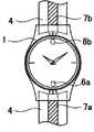
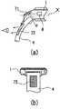
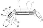
図1は、本発明の第1の実施例の電子腕時計を説明する図であって、図1(a)は電子腕時計の正面図であり、図1(b)は電子腕時計を6時方向から見た側面図である。
これらの図において、1は本体ケース、2は表示装置、3はスイッチ手段、4はバンド、5は開口部、6は発光素子、7は導光手段である。図1においては、発光素子6から出射した光は矢印で示している。1A and 1B are diagrams for explaining an electronic wristwatch according to a first embodiment of the present invention. FIG. 1A is a front view of the electronic wristwatch, and FIG. FIG.
In these drawings, 1 is a main body case, 2 is a display device, 3 is switch means, 4 is a band, 5 is an opening, 6 is a light emitting element, and 7 is light guide means. In FIG. 1, the light emitted from the
発光素子6を本体ケース1の内部に配置し、導光手段7をバンド4に配置することにより、発光素子6が発した光が、本体ケース1の6時方向に設ける開口部5を通り、バンド4に設置された導光手段7に入射する。導光手段7は、所定の方向に発光素子6の光を導くことができる。 By arranging the
所定の方向とは、光を発したい方向であって、例えば、本体ケース1の表面方向やバンド4の表面方向である。導光手段7は、その方向に所定の面が向くように配置されている。この所定の面とは、導光手段7の一平面や端面であって、光を発する面である。 The predetermined direction is a direction in which light is desired to be emitted, for example, the surface direction of the
このようにすることで、入射した光をその所定の面方向に導き使用者から視認可能となるのであるが、バンド4自体に発光素子を設けなくても、使用者からはあたかもバンド4が発光しているように見えるのである。 By doing so, the incident light is guided in the predetermined plane direction and can be visually recognized by the user. However, even if no light emitting element is provided in the
開口部5は、バンド4の端面と本体ケース1とが嵌合する際に、本体ケース1に設ける発光素子6とバンド4に設ける導光手段7とが遮蔽物なく対向するように本体ケース1に開口したものである。このようにすることで、発光素子6からの光が本体ケース1に遮蔽されることなく導光手段7に到達し、導光手段7は所定の方向に光を発することができる。 When the end face of the
バンド4と本体ケース1との接続は、知られている時計のバンド留め構造をもって行うことができるから、その説明は省略する。
表示装置2は、針による時刻の報知を行う、所謂アナログ表示式の文字盤を例にして説明しているが、もちろんそれに限定するものではなく、数字や絵文字を用いて時刻を報知する、所謂デジタル表示式のものでもよい。Since the connection between the
The
本体ケース1またはバンド4には、知られている金属素材や樹脂素材などを用いることができる。図1に示した実施例では、可撓性のある樹脂素材または皮革素材でバンドを構成する例を示しているが、もちろんこれに限定されない。知られている複数のコマを回動部で連結した形状のバンドや、ブレスレット形状であってもかまわない。複数のコマを用いるバンドの構成については後述する。 For the
発光素子6は、特に限定しないが、LED(Light Emitting Diode:発光ダイオード)を用いることができる。EL(Electro Luminescence)素子や電球なども用いることができるが、発光するために必要な電力がより少なくて済むものが好ましい。 Although it does not specifically limit the
本発明の実施例では、発光色は特に限定しないが、発光させたときの視認性やファッション性(表現)を鑑みるならば、発光色は、多色が好ましい。例えば、LEDに印加する駆動電流を制御することにより白,青,緑,黄,橙,赤等を発色できるカラーLEDや、これらを複数組み合わせてもかまわない。 In the examples of the present invention, the emission color is not particularly limited, but the emission color is preferably multicolored in view of the visibility and fashionability (expression) when the light is emitted. For example, a color LED that can develop white, blue, green, yellow, orange, red, etc. by controlling the drive current applied to the LED, or a combination of these may be used.
また、この場合、例えば、発光素子が、LED発光素子の場合に、LED発光素子を、赤色(R)LED発光素子、緑色(G)LED発光素子、青色(B)LED発光素子の3色のLEDから構成し、フィルターR,G,BをこれらのLEDから発せられたR,G,Bのそれぞれの光のみを透過するフィルターとすれば、R,G,Bの発光箇所、形状などを選択することができ、発光による視認性やファッション性の向上を図ることができる。 In this case, for example, when the light emitting element is an LED light emitting element, the LED light emitting element is selected from three colors of a red (R) LED light emitting element, a green (G) LED light emitting element, and a blue (B) LED light emitting element. If it is composed of LEDs and the filters R, G, B are filters that transmit only the R, G, B light emitted from these LEDs, the light emission location, shape, etc. of R, G, B can be selected. It is possible to improve visibility and fashionability by light emission.
もちろん、発光は可視光に限定するものではなく、紫外線等も使用できる。例えば、365nmの波長を有する紫外線である。この場合、後述する導光手段7の中にビタミンB2(リボフラビン)を含有する水溶液または素材を封止することで、紫外線域の非可視光束を照射すると、導光手段7を緑黄色に蛍光発光させることができる。 Of course, light emission is not limited to visible light, and ultraviolet light or the like can be used. For example, ultraviolet rays having a wavelength of 365 nm. In this case, by sealing an aqueous solution or material containing vitamin B2 (riboflavin) in the light guide means 7 to be described later, when the invisible light beam in the ultraviolet region is irradiated, the light guide means 7 emits fluorescent light in green and yellow. be able to.
すなわち、後述するように、発光素子が、紫外線発光素子(UV−LED)、電子線発光素子とすることもでき、この場合には、バンドパスフィルタを配置することによって、UV−LED、電子線発光素子から発せられた紫外線の波長、電子線の波長を選択して透過させ、紫外線、電子線により所定の色に発光する蛍光体を配置しておけば、発光箇所、形状などを選択することができ、発光による視認性やファッション性の向上を図ることができる。 That is, as will be described later, the light emitting element may be an ultraviolet light emitting element (UV-LED) or an electron beam light emitting element. In this case, by arranging a band pass filter, the UV-LED, the electron beam If you select the wavelength of ultraviolet rays emitted from the light-emitting element and the wavelength of electron beams and transmit them, and place a phosphor that emits light of a predetermined color by ultraviolet rays and electron beams, you can select the light emission location, shape, etc. It is possible to improve visibility and fashionability by light emission.
導光手段7は、空気と構成する材質との間の屈折率差による反射を利用して、光を所定の方向へ導くものであって、知られている部材を用いることができる。特に限定しないが、導光手段7は、アクリル樹脂で構成する透明板で構成することができ、所定の面に光をむらなく散光させるための微細な模様が印刷またはパターニングされている。 The light guide means 7 guides light in a predetermined direction by utilizing reflection due to a difference in refractive index between air and a constituent material, and a known member can be used. Although it does not specifically limit, the light guide means 7 can be comprised with the transparent plate comprised with an acrylic resin, and the fine pattern for making light diffuse evenly on the predetermined surface is printed or patterned.
もちろん、知られている液晶表示装置のバックライト等に採用されている導光板を用いることができる。また、光ファイバを用いてもかまわない。
また、導光手段7の表面の一部または全体に、知られている光散乱部材を貼り付けてもかまわない。さらにまた、ハーフミラー処理層や反射部材、着色層やめっき処理層を形成してもかまわない。Of course, it is possible to use a light guide plate employed in a backlight or the like of a known liquid crystal display device. An optical fiber may be used.
Further, a known light scattering member may be attached to a part or the whole of the surface of the light guide means 7. Furthermore, a half mirror treatment layer, a reflective member, a colored layer, or a plating treatment layer may be formed.
重要なことは、発光素子6からの光を所定の方向に導光することである。導光手段7の発光明度を均一化したり、非発光時の装飾性を向上させることは、視認性やファッション性の向上を鑑みてより好ましいものである。 What is important is to guide the light from the
さらにバンド4には導光手段7に隣接して知られている蓄光部材を設置することができる。蓄光部材による光の吸収,発光を利用して、後述するCPU21などの電子腕時計の制御手段によって発光素子6を所定の時間間隔で間欠駆動すると、発光素子6が発光していない期間も蓄光部材が発光を継続するので、バンド4の発光を維持することができる。そのため、非常に少ない消費電力でバンド4を長時間に渡って連続的に発光させることが可能となる。 Furthermore, a known phosphorescent member can be installed in the
スイッチ手段3は、図示しない電子腕時計の制御手段と電気的に接続されており、使用者が操作することによって、発光素子6の発光を制御する。例えば、連続点灯,点滅,間欠点灯,消灯,発光色の変更などである。 The switch means 3 is electrically connected to control means of an electronic wristwatch (not shown), and controls the light emission of the
また、発光素子6を図示しないセンシング手段からの信号入力をトリガとして発光するようにして、スイッチ手段3によってセンシング手段を有効化したり無効化したりしてもよい。 Further, the
センシング手段としては、例えば、振動を検知して信号を出力する振動センサ、傾斜を検知して信号を出力する傾斜センサ、加速度を検知して信号を出力する加速度センサ、温度センサや気圧センサ、通信手段を有する情報装置において電波の受信を検知して信号を出力するセンサなどである。
[第2の実施例:図2]
図2は、本発明の第2の実施例の電子腕時計を説明する正面図であり、電子腕時計の6時方向と12時方向との両方にそれぞれ発光素子6a,6bと導光手段7a,7bとを設置するものである。発光素子6a,6bは、それぞれが配置される側のバンド4の方向に光を発し、導光手段7a,7bがそれを受光する。各導光手段は、受光した光を導いて使用者が発光を視認できるようにする。As a sensing means, for example, a vibration sensor that detects vibration and outputs a signal, an inclination sensor that detects inclination and outputs a signal, an acceleration sensor that detects acceleration and outputs a signal, a temperature sensor or an atmospheric pressure sensor, communication A sensor that detects reception of radio waves and outputs a signal in an information device having a means.
[Second Embodiment: FIG. 2]
FIG. 2 is a front view for explaining an electronic wristwatch according to a second embodiment of the present invention.
また、発光素子6a,6bを同時または交互に点滅させたり、それぞれ異なる色で発
光させたりしてもよいのはもちろんである。
このような構成とすることによって、バンド4の発光範囲をより大きくすることができるため、使用者のみならず周囲からの視認性も一層向上する。
[第3の実施例:図3]
図3は、本発明の第3の実施例の電子腕時計を説明する正面図であり、電子腕時計の6時方向に発光素子6a,6bと導光手段7a,7bとを設置するものである。Of course, the
By adopting such a configuration, the light emission range of the
[Third embodiment: FIG. 3]
FIG. 3 is a front view for explaining an electronic wrist watch according to a third embodiment of the present invention, in which light emitting
これら2つの導光手段7a,7bの間には、遮光性部材8が設けてある。この遮光性部材8により、発光や導光が互いに干渉しないようになっている。
このような構成とすることによって、個々の発光素子が、それぞれバンド4上の所定位置に独立して設置された導光手段を発光させるので、例えば、発光素子の発光を報知手段として用いる場合に、導光手段7a,7bの発光状態により報知する情報を変更したり、導光手段7a,7bの組み合わせによって報知する情報に所定の意味を持たせることもできる。A light shielding member 8 is provided between the two light guiding means 7a and 7b. The light shielding member 8 prevents light emission and light guide from interfering with each other.
By adopting such a configuration, each light emitting element causes the light guide means installed independently at a predetermined position on the
例えば、導光手段7aを赤色,導光手段7bを青色に発光させるようにすることができる。また、一方の導光手段、例えば、導光手段7bのみ毎正時に点滅させてもよい。このように、それぞれ異なる色で発光させたりすることで、より一層の視認性と表現の多様性、を有する情報の報知が可能となるとともに、装飾効果を得られる。 For example, the light guide means 7a can emit light in red and the light guide means 7b can emit light in blue. Further, only one of the light guide means, for example, the light guide means 7b may be blinked every hour. As described above, by emitting light with different colors, it is possible to notify information having further visibility and diversity of expression and obtain a decoration effect.
図3に示した実施例では、上述の構成を本体ケース1の6時方向に設ける場合を説明したが、もちろん、本体ケース1の12時方向に設けてもよいし、12時方向と6時方向との両方に設けてもよい。
[第4の実施例:図4]
図4(a)(b)は、本発明の第4の実施例の電子腕時計を説明する正面図であり、電子腕時計の6時方向に発光素子6と導光手段7とを設置するものであるが、導光手段7の形状が第1の実施例とは異なる例を示すものである。バンド4の短手方向を導光手段7の幅とすると、この幅が本体ケース1から遠ざかるにつれ漸次細くなるようになっている。In the embodiment shown in FIG. 3, the case where the above-described configuration is provided in the 6 o'clock direction of the
[Fourth embodiment: FIG. 4]
4 (a) and 4 (b) are front views for explaining an electronic wristwatch according to a fourth embodiment of the present invention, in which a
本発明の装着型電子機器である電子腕時計を腕に装着した際、バンド4の6時方向が使用者側となるから、導光手段7の幅を使用者の目につく部分を広くすることで、発光素子6の発光輝度が同一であっても見かけ上明るく感じるようになるのである。 When the electronic wrist watch, which is the wearable electronic device of the present invention, is worn on the wrist, the 6 o'clock direction of the
従って、発光素子6に印加する駆動電力を低減しても、使用者が感じるバンド4の発光状態は、さほど暗くならないのであるから、発光素子6の駆動に伴う消費電力を低減することができる。 Therefore, even if the driving power applied to the
図4(b)に示した実施例では、発光素子6を2つ設ける例を示したが、これに限定するものではない。発光素子6を構成するLEDの発光輝度や消費電力などを鑑みて自由に選択することができる。また、2つの発光素子を交互に点滅させたり、それぞれ異なる色で発光させたりしてもよいのはもちろんである。 In the embodiment shown in FIG. 4B, an example in which two
図4に示した実施例では、導光手段7は本体ケース1の6時方向に設ける場合を説明したが、もちろん、このような形状の導光手段7を本体ケース1の12時方向に設けてもよい。そのような構成とすれば、使用者のみならず、12時方向のバンド4が発光するので、第三者にも発光状態が視認し易くなるので、第三者に対しても視認性と表現の多様性が向上する。例えば、夜間外出時に発光しておけば、他の交通機関の運転者からの視認性も向上し、交通事故などの不測の事態を回避することができる。もちろん、12時方向と6時方向との両方に設けてもよい。
[第5の実施例:図5]
図5は、本発明の第5の実施例の電子腕時計を説明する正面図である。In the embodiment shown in FIG. 4, the light guide means 7 is provided in the 6 o'clock direction of the
[Fifth embodiment: FIG. 5]
FIG. 5 is a front view for explaining an electronic wrist watch according to a fifth embodiment of the present invention.
図5に示したように、本発明の電子腕時計の6時方向に発光素子6a,6b,6cと、それぞれに対応する導光手段7と開口部70a,70b,70cとを設置するものである。 As shown in FIG. 5, the light-emitting
図5は、本発明の装着型電子機器である電子腕時計の6時方向に発光素子6a,6b,6cと開口部70a,70b,70cとをそれぞれの導光手段7の表面の一部に配置するものであり、この開口部70a,70b,70cから、それぞれの導光手段7の発光を視認できるようになっている。それぞれの導光手段7は、図示しない遮光性部材によって仕切られており、発光や導光が互いに干渉しないようになっている。 FIG. 5 shows that the
開口部70a,70b,70cは、文字,記号,図形などの形状にすることができる。このようにすることで、発光をより際立たせることができる。
また、発光素子6a,6b,6cにそれぞれ対応して個別に発光を制御するようにしてもよい。例えば、本発明の装着型電子機器を電子腕時計型の生体測定装置とし、ある計測した生体情報からトレーニング状態を報知するとき、目標に対してオーバートレーニング状態であれば発光素子6aを、アンダートレーニング状態であれば発光素子6cを、目標のトレーニング状態であれば発光素子6bをそれぞれ所定の時間、点滅させるのである。もちろん、発光色を変えることで更に注意を促すようにしてもよい。The
Moreover, you may make it control light emission separately corresponding to each light emitting
このような構成とすれば、より一層の視認性と表現の多様性が得られる情報の報知が可能となる。さらに、開口部70a,70b,70cを透明樹脂や半透明樹脂などで封止さ
せてもよい。これにより、非発光時の質感や装飾性を向上させることもできる。With such a configuration, it is possible to notify information that provides further visibility and diversity of expression. Furthermore, the
図5に示した実施例では、上述の構成を本体ケース1の6時方向に設ける場合を説明したが、もちろん、本体ケース1の12時方向に設けても、12時方向と6時方向との両方に設けてもよい。
[第6の実施例:図6]
図6は、本発明の第6の実施例の電子腕時計を説明する図であって、図6(a)は、電子腕時計を3時方向側面から見た内部の状態を模式的に示す側面図であり、図6(b)は、電子腕時計を6時方向のバンド4から見た側面図である。In the embodiment shown in FIG. 5, the case where the above-described configuration is provided in the 6 o'clock direction of the
[Sixth embodiment: FIG. 6]
FIG. 6 is a diagram for explaining an electronic wrist watch according to a sixth embodiment of the present invention. FIG. 6 (a) is a side view schematically showing an internal state of the electronic wrist watch viewed from the side of the 3 o'clock direction. FIG. 6B is a side view of the electronic wrist watch viewed from the
図6に示す実施例においては、1つの発光素子に対して2つの導光手段を用いる場合を示すものである。71は第1の導光手段、72は第2の導光手段、Xは仮想直線である。
図6(a)に示したように、本体ケース1内部の6時方向端部付近には、反射部材で構成する第1の導光手段71が設置されており、発光素子6が発した光をバンド4上に設置された第2の導光手段72に導く。In the embodiment shown in FIG. 6, a case where two light guide means are used for one light emitting element is shown. 71 is a first light guiding means, 72 is a second light guiding means, and X is a virtual straight line.
As shown in FIG. 6 (a), the first light guide means 71 made of a reflective member is installed in the vicinity of the 6 o'clock direction end inside the
また、第1の導光手段71は、図示しない表示装置2に平行な仮想直線Xに対して所定の角度θを持ち、発光素子6が発した光を散乱や拡散等を行わずに本体ケース1の6時方向のバンド4の表面方向に反射させる。 The first light guiding means 71 has a predetermined angle θ with respect to a virtual straight line X parallel to the display device 2 (not shown), and does not scatter or diffuse light emitted from the
第2の導光手段72は、反射部材で構成され、入射したこの光を散乱や拡散等を行わずに所定の方向、例えばバンド4の表面方向へ反射させる。図6(a)においては、発光素子6から出射した光は矢印で示している。 The second light guiding means 72 is formed of a reflecting member, and reflects the incident light in a predetermined direction, for example, the surface direction of the
図6(a)において、この矢印は、第1の導光手段71から第2の導光手段72への導光を本体ケース1の外側を通る実施例を示しているが、もちろんこれに限定されない。
第1の導光手段71で導光された光は、バンド4の内部を通り第2の導光手段72に到達するようにしてもかまわない。In FIG. 6A, this arrow indicates an embodiment in which the light guide from the first light guide means 71 to the second light guide means 72 passes through the outside of the
The light guided by the first light guiding means 71 may pass through the
その場合は、第2の導光手段72は、反射部材ではなく、すでに説明した所定の方向に導光する導光手段とすることで、第2の導光手段72の所定の面から発光素子6の光を発することができる。 In that case, the second light guide means 72 is not a reflecting member but a light guide means for guiding light in the predetermined direction already described, so that a light emitting element is formed from a predetermined surface of the second light guide means 72. 6 light can be emitted.
図6(b)に示したように、第2の導光手段72は、バンド4上において本体ケース1と離間して設けることができるから、デザイン上の制約を受けずにバンド4を発光させることができる。 As shown in FIG. 6B, since the second light guiding means 72 can be provided on the
発光素子6は、指向性の高い光を発する発光素子で構成することもできる。この場合、発光素子6が発した光を、拡散や散乱を行わずに、第1の導光手段71から第2の導光手段72への導光を介して、使用者の顔面の方向に導けば、周囲を照明せずに使用者のみがバンドの発光を確認できる。 The
例えば、映画館や消灯中の航空機の客室内などの周囲を照明してしまうと不都合が生じるような場所においても、周囲を照明せずにバンドの発光を使用者が視認することができる。 For example, even in places where it would be inconvenient to illuminate the surroundings such as in a movie theater or in a passenger cabin of an unlit aircraft, the user can visually recognize the emission of the band without illuminating the surroundings.
本発明の装着型電子機器である電子腕時計に、先に説明したセンシング手段を搭載し、このセンシング手段からの情報に基づいてバンド4を発光させる場合においては、発光が予期せず発生することがあって、そのような状況であっても、発光素子6が発した光を、拡散や散乱を行わずに、第1の導光手段71から第2の導光手段72への導光を介して、
使用者の顔面の方向に導けば、発光を周囲の第三者に知られることなく使用者が認識することができる。When the electronic wristwatch that is the wearable electronic device of the present invention is equipped with the sensing means described above, and the
If the user is guided in the direction of the user's face, the user can recognize the light emission without the surrounding third party knowing it.
このように、導光手段を第1の導光手段71,第2の導光手段72で構成することによよって、導光手段を本体ケース1に配置される発光素子6の近傍まで延長しなくともバンド4を発光させることが可能となる。
[第7の実施例:図7]
図7は、本発明の第7の実施例の電子腕時計を説明する図であって、図7(a)は、電子腕時計の正面図であり、図7(b)は、電子腕時計を3時方向側面から内部を見た状態を模式的に示す側面図である。In this way, by configuring the light guide means by the first light guide means 71 and the second light guide means 72, the light guide means is extended to the vicinity of the
[Seventh embodiment: FIG. 7]
7A and 7B are diagrams for explaining an electronic wristwatch according to a seventh embodiment of the present invention. FIG. 7A is a front view of the electronic wristwatch, and FIG. It is a side view which shows typically the state which looked at the inside from the direction side surface.
図7において、32は、第1の導光手段71の端部に設ける突起部であり、発光素子6から出射した光は矢印で示している。
図7に示した実施例では、発光素子6を本体ケース1の12時方向に設置している。表示装置2は、例えば、針による時刻の報知を行うアナログ表示式の文字盤であり、透光性部材で構成されている。この表示装置2の裏側に、第1の導光手段71を設置している。In FIG. 7, 32 is a projection provided at the end of the first light guide means 71, and the light emitted from the
In the embodiment shown in FIG. 7, the
第1の導光手段71は、表示装置2の方向に光を導く構成を有するとともに、6時方向の端部には突起部32を有している。突起部32は、第1の導光手段71に入射した光をバンド4上に設置する第2の導光手段72に導く導光機能を持つ。 The first light guiding means 71 has a configuration for guiding light in the direction of the
すなわち、発光素子6から出射した光は、第1の導光手段71により表示装置2を通して本発明の電子腕時計の正面に導かれ、あたかも表示装置2が発光しているがごとく見えるのである。またその光は、突起部32により第2の導光手段72に導かれ、バンド4の表面も発光させるのである。 That is, the light emitted from the
このような構成とすることにより、発光素子6が発する光が、バンド4の発光だけでなく、表示装置2の照明効果も有するため、時刻の認識のために必要な表示装置2を照明する手段が不要となり、本発明の電子腕時計をより小型にすることができる。もちろん、表示装置2も発光することから、より一層の装飾効果が得られることはもちろんである。 With such a configuration, the light emitted from the
また、突起部32や発光素子6の設置位置は、図7に示す例に限定されるものではない。発光素子6を本体ケース1の3時方向に設け表示装置2の中心方向に光を照射するようにし、突起部32を6時方向と12時方向との両方に設け、それぞれの方向のバンド4に設ける第2の導光手段72に光を導いてもよい。また、この場合、発光素子6を本体ケース1の9時方向、3時方向に設けるなど、発光素子6の位置は特に限定されるものではなく、適宜変更することができる。 Moreover, the installation position of the
さらに、突起部32は、第1の導光手段71と別体で形成してもよい。
さらにまた、図7(b)では、突起部32の端面と第2の導光手段72の端面とがわずかに離間して対向している実施例を示したが、この端面同士を接してもかまわない。
[第8の実施例:図8]
図8は、本発明の第8の実施例の電子腕時計を説明する図であって、図8(a)は、電子腕時計の正面図であり、図8(b)は、電子腕時計を3時方向側面から見た内部の状態を模式的に示す側面図である。Further, the
Furthermore, FIG. 7B shows an embodiment in which the end face of the
[Eighth embodiment: FIG. 8]
FIG. 8 is a diagram for explaining an electronic wrist watch according to an eighth embodiment of the present invention. FIG. 8 (a) is a front view of the electronic wrist watch, and FIG. It is a side view which shows typically the internal state seen from the direction side surface.
図8において、5は本体ケース1に設ける開口部であり、発光素子6から出射した光は矢印で示している。11は表示装置2を保護する風防ガラスである。
図8に示した実施例では、開口部5を本体ケース1の風防ガラス11方向とバンド4に設置する第2の導光手段72の方向との両方に設けている。そして、風防ガラス11方向
の開口部5は、この開口部5を埋めるように第1の導光手段71が嵌合し、本体ケース1からは突出しないように設けている。In FIG. 8,
In the embodiment shown in FIG. 8, the
従って、第1の導光手段71は、光を発する方向が風防ガラス11方向と第2導光手段72の2方向となる。
発光素子6は、本体ケース1内部に設置しており、光の出射方向は、第1の導光手段71側である。Therefore, the first light guide means 71 emits light in the two directions of the
The
このような構成とすることにより、発光素子6が発した光の一部が、第1の導光手段71に入射し、第1の導光手段71を介して、風防ガラス11方向へと光が導かれて、第1の導光手段71の開口部5から上方へ放出される。 With such a configuration, a part of the light emitted from the
また、発光素子6が発した光の一部は、第1の導光手段71の開口部5からバンド4の第2の導光手段72の方向へと光が導かれ、バンド4の表面から放出される。
従って、発光素子6が発した光が、これらの両方向へ導かれることになるため、使用者は、本体ケース1の一部とバンド4とが発光しているように見えるのである。Further, part of the light emitted from the
Accordingly, since the light emitted from the
図8に示した実施例では、第1の導光手段71は、図8(a)に示したように、開口部5に嵌合しているため矩形形状を有しているが、もちろんこれに限定するものではない。
また、時計本体に開口部を設ける代わりに、または時計本体に開口部を設けるとともに、電子腕時計の所謂ベゼル部分に開口部5を設け、第1の導光手段71の端面を露出しておけば、表示装置2の周囲を発光させることができる。このような構成とすれば、より一層の視認効果、装飾効果を得ることができる。
[第9の実施例:図9]
図9は、本発明の第9の実施例の電子腕時計を説明する正面図である。図9において、30は遮光性部材、31はバンド4の開口部である。In the embodiment shown in FIG. 8, the first light guide means 71 has a rectangular shape because it is fitted in the
Further, instead of providing an opening in the watch body, or providing an opening in the watch body and providing an
[Ninth embodiment: FIG. 9]
FIG. 9 is a front view for explaining an electronic wrist watch according to a ninth embodiment of the present invention. In FIG. 9, 30 is a light shielding member, and 31 is an opening of the
図9(a)は、導光手段7a,7bの表面の一部に、遮光性部材30を配置している。
遮光性部材30は、文字,記号,図形等の形状をしており、導光手段7a,7bに光が入射すると、遮光性部材30の周囲は発光するが、遮光性部材30の下からの光は遮光されるので、遮光性部材30の形状が際立ち、高い装飾効果を得ることができる。In FIG. 9A, the
The
図9(a)に示した実施例では、遮光性部材30は、「1」と「2」という文字の形状である。
また、遮光性部材30を含む導光手段7a,7bの表面に、図示しないが、知られているハーフミラー処理層を設置することにより、導光手段7a,7bに光が入射した場合のみに、遮光性部材30の形状が視認可能とすることができる。これにより、より一層の装飾効果を得ることができる。In the embodiment shown in FIG. 9A, the light-shielding
Further, although not shown in the figure, on the surface of the light guide means 7a and 7b including the
図9(b)は、導光手段7a,7bの表面の一部に、開口部31を配置しており、この開口部31から、導光手段7a,7bの発光を視認できるようになっている。
開口部31は、文字,記号,図形等の形状をしており、導光手段7a,7bに光が入射すると、バンド4の表面は開口部31の周囲が遮光性であるので、バンド4の開口部31のみが発光するので、所定の形状の模様などを発光により際立たせることができる。In FIG. 9B, an
The
図9(b)に示した実施例では、開口部31は、月と星との模様である。
これにより、バンド4を所定の形状や模様にワンポイントで発光させることができ、高い装飾効果を得ることができる。In the embodiment shown in FIG. 9B, the
Thereby, the
また、開口部31を透明樹脂や半透明樹脂などで封止させてもよい。これにより、非発
光時の質感や装飾性を向上させることができる。
[第10の実施例:図10]
図10は、本発明の第10の実施例の電子腕時計を説明する正面図である。Further, the
[Tenth embodiment: FIG. 10]
FIG. 10 is a front view for explaining an electronic wrist watch according to a tenth embodiment of the present invention.
図10において、符号41は、バンド4を構成するコマである。
図10は、金属や樹脂部材よりなる複数のコマを繋ぎ合わせて構成するバンド4において、本体ケース1との接続端部となるコマ41に導光手段7を設置している実施例を示すものである。In FIG. 10,
FIG. 10 shows an embodiment in which a light guide means 7 is installed on a
このような構成とすることにより、バンド4の長さを調節するときには、導光手段7を設置しているコマ41とは異なるコマ41を取り除いたり加えたりすることによって、バンド4の発光機能を維持したまま容易にバンド4の長さ調節が可能である。 With this configuration, when the length of the
また、図示はしないが、コマごとに導光手段7を設けてもよい。その場合は、コマ同士が当接する端部に開口部を設け、導光手段7の端部を設けて、複数のコマの導光手段7をを連続して光が導光されるようにすることにより、コマ同士を連結する連結具があっても発光素子6から出射される光を導光することができる。 Further, although not shown, the light guide means 7 may be provided for each frame. In that case, an opening is provided at an end where the frames come into contact with each other, and an end of the light guide means 7 is provided so that light is continuously guided through the light guide means 7 of the plurality of frames. Thereby, even if there exists a connection tool which connects tops, the light radiate | emitted from the
すなわち、導光手段7を持つコマを取り除いたり追加したりしても、バンド4の発光機能に支障がなく、バンド4の発光機能を維持したまま容易に長さを調節することができる。 That is, even if a frame having the light guide means 7 is removed or added, the light emission function of the
また、複数のコマのうち、発光させるコマは、全部を発光させる場合の他、例えば、1個おきに発光させるなど、適宜選択することができ、このような発光状態を選択することによって、装着者に異なる情報を報知することができる。 In addition, among the plurality of frames, the light-emitting frames can be selected as appropriate, for example, every other light-emitting element, for example, every other light-emitting element. Different information can be notified to the person.
以下、本発明の装着型電子機器を生体測定装置として、身体装着型運動トレーニング支援装置に適用した最良の形態を構成図を用いて説明する。
以下の実施例においては、単に身体装着型運動トレーニング支援装置と称することにする。また、生体情報を脈波として、この脈波を計測することで生体情報を得る場合を例にして説明する。Hereinafter, the best mode of applying the wearable electronic apparatus of the present invention to a body wearable exercise training support device as a biometric device will be described with reference to the configuration diagram.
In the following embodiment, it will be simply referred to as a body-mounted exercise training support device. Further, a case where biological information is obtained by measuring the pulse wave using biological information as a pulse wave will be described as an example.
さらにまた、身体装着型運動トレーニング支援装置の動作に関わる制御をCPU(Central Processing Unit:中央処理装置)を用いて行う場合を例にして説明する。 Furthermore, a case where control related to the operation of the body-worn exercise training support apparatus is performed using a CPU (Central Processing Unit) will be described as an example.
さらに、以下の実施例の身体装着型運動トレーニング支援装置は、腕時計型とし使用者の手首などに装着する場合を例にして説明する。
[第11の実施例:図11、図12]
図11は、本発明の第11の実施例の身体装着型運動トレーニング支援装置の3時方向側面から見た内部の状態を模式的に示す側面図である。Further, the body-worn exercise training support apparatus of the following embodiment will be described by taking as an example a case of wearing a wristwatch type on a wrist of a user.
[Eleventh embodiment: FIGS. 11 and 12]
FIG. 11: is a side view which shows typically the internal state seen from the 3 o'clock direction side surface of the body mounting type | mold exercise training assistance apparatus of the 11th Example of this invention.
図11において、1は本体ケース、2は表示装置、3はスイッチ手段、4はバンド、6は発光素子、7は導光手段、21はCPU、24は脈波検出部、25は脈波I/F(インターフェース)、26は発光駆動回路、27は表示駆動回路、28はスイッチI/Fである。99は使用者であり、その視線を模式的に示している。 In FIG. 11, 1 is a main body case, 2 is a display device, 3 is a switch means, 4 is a band, 6 is a light emitting element, 7 is a light guide means, 21 is a CPU, 24 is a pulse wave detector, and 25 is a pulse wave I. / F (interface), 26 is a light emission drive circuit, 27 is a display drive circuit, and 28 is a switch I /
なお、点線矢印は光路を、実践矢印は電気的な信号の流れを模式的に示している。
図12は、本発明の身体装着型運動トレーニング支援装置の電気回路を説明するための
ブロック図である。The dotted arrow indicates the optical path, and the practical arrow schematically indicates the flow of electrical signals.
FIG. 12 is a block diagram for explaining an electric circuit of the body-worn exercise training support apparatus of the present invention.
図12において、22はROM(Read Only Memory:読み出し専用記憶装置)、23はRAM(Random Access Memory:随時読み出し書き込み記憶装置)である。 In FIG. 12, 22 is a ROM (Read Only Memory), and 23 is a RAM (Random Access Memory).
図11においては、図面左側に本体ケース1を腕時計でいえば3時方向または9時方向から見た断面を模式的に示しており、この本体ケース1内に配設する要素への電気的な接続は、図面右側に回路ブロック図形式で表記している。 In FIG. 11, a cross section of the
発光素子6および導光手段7で第1の報知手段を構成し、表示装置2が第2の報知手段となっている。これら報知手段の動作は、CPU21で制御されている。
スイッチ手段3は、使用者情報入力手段である。少なくとも1つのスイッチからなる。使用者は、このスイッチ手段3を操作して使用者情報を入力する。入力された使用者情報は、スイッチI/F28を介してCPU21に送られる。The
The switch means 3 is a user information input means. It consists of at least one switch. The user operates the switch means 3 to input user information. The input user information is sent to the
CPU21は、本発明の身体装着型運動トレーニング支援装置の各回路を制御する中枢部となる演算処理ユニットである。
ROM22は、CPU21が実行する処理プログラムや演算処理などに必要な定数などが格納されている。ROM22に格納しているプログラムについては後述する。The
The
RAM23は、CPU21が実行する演算処理結果などを一時的に格納しておくことのほか、使用者の年齢や安静時心拍数などの使用者情報を格納する。
また、本発明の身体装着型運動トレーニング支援装置を使用するたびに使用者情報を入力することはわずらわしいため、使用者情報を保持しておくことが望ましい。このため、RAM23は、電気的に書き換え可能な不揮発性記憶装置で構成することができる。The
Moreover, it is troublesome to input user information every time the body-worn exercise training support apparatus of the present invention is used, so it is desirable to retain user information. Therefore, the
脈波検出部24は、使用者の脈波を検出する検出部であって、特に限定しないが、胸部に装着して脈波を検出する電極を持った胸ベルト状の心電位検出方式や、耳朶や指先に挟んで装着して血流の変化を発光素子と受光素子とを利用して光で脈波を検出する光学方式、生体の心臓の鼓動が血管の拡張と収縮運動となって皮膚に伝達し、この皮膚の表面振動を検出する圧力容積振動法を用いた方式などを用いることができる。 The pulse
これらの構成や動作については、すでに知られているものであるからその説明は省略する。
脈波検出部24は、本体ケース1またはバンド4に設けることもできるが、これらと独立した別体とすることもできる。そのような場合は、脈波検出部24とCPU21とは、有線または無線で信号の送受を行う。Since these configurations and operations are already known, description thereof will be omitted.
The pulse
脈波I/F25は、脈波検出部24のアナログ出力信号を所定の間隔で取り込み、デジタル信号に変換して出力する。図示はしないが、脈波検出部24からの出力信号が無線送信される場合は、これを受信するための受信回路を有する。 The pulse wave I /
発光駆動回路26は、CPU21からの制御情報に応じて発光素子6に流れる電流を制御する。電流制御は、アナログ制御であっても、時分割駆動によるデジタル制御であってもよい。 The light
発光素子6は、本体ケース1の内部に配置し、導光手段7をバンド4に配置することにより、発光素子6が発した光が、バンド4に設置された導光手段7に入射する。
導光手段7は、入射光をバンド4の厚さ方向外側に散光することで、使用者から視認可
能となるようにする。このようにすることで、バンド4に発光素子を設けなくても、バンド4を発光させることができる。The
The light guide means 7 makes the incident light visible to the user by scattering the incident light outward in the thickness direction of the
もちろん、本体ケース1に図示しない開口部を設け、図8の実施例と同様に、風防ガラス11方向の開口部5を埋めるように、開口部に導光手段7を嵌合しておけば、その開口部から発光素子6からの光を散光させることができる。 Of course, if the
このような構成とすることによって、本体ケース1の一部を発光させることができる。
この発光素子6および導光手段7で第1の報知手段を構成するが、導光手段7は、複数設けることができる。これにより、発光素子6が発する光をより多くバンド4に伝達し、バンド4をより鮮明に発光させることができる。By setting it as such a structure, a part of
The
また、導光手段の形状などにより、バンド4を所定の状態に発光させることができるから、バンド4の発光面積を大きくしても、本装置としての消費電力が増加することはないのである。 Further, because the
なお、バンド4と本体ケース1との接続は、知られている腕時計のバンド留め構造をもって行うことができるから、その説明は省略する。
表示駆動回路27は、CPU21からの表示情報を受け取ると、表示装置2に必要な形式の電気信号に変換して出力することで表示装置2を駆動する。Note that the connection between the
When the
スイッチI/F28は、スイッチ手段3を操作して入力された使用者情報をCPU21が受信できる形式の電気信号に変換して出力する。CPU21はこれを受け取り、使用者情報として取り込みRAM23に格納する。 The switch I /
表示装置2は、第2の報知手段であって、心拍数やトレーニング指標や時刻や使用者情報や装置情報などを表示する。
発光素子6および導光手段7による第1の報知手段は、使用者が運動中であっても本発明の身体装着型運動トレーニング支援装置からの支援情報や装置情報を報知することができ、これは使用者の注意を引き付ける役割が強い報知手段であるのに対して、この第2の報知手段は、より詳細な情報の報知を行うものである。The
The first notification means by the
表示装置2は、例えば、液晶表示装置を用いることができる。液晶表示装置は、文字または絵文字を表示することができるとともに、軽量で低消費電力な表示装置として好適である。液晶表示装置は、カラー表示ができるもの、ドットマトリクス表示によるグラフィックス表示ができるものを用いてもかまわない。 As the
また、表示装置2は、強誘電性液晶表示装置などのメモリ性を有する液晶表示装置を用いることもできる。メモリ性を有する液晶表示装置は、表示を切り替えるときのみ電力を必要とし、一度表示をするとその状態を保持し、その保持には電力を消費しないという特性を有している。このため表示装置2は、その表示中は電力を消費せず、装置として低消費電力化が行える。 The
もちろん、アナログ表示式時計のように指針により情報を表示する、所謂アナログ表示式の文字盤であってもよい。
CPU21は、脈波I/F25からのデジタル信号から脈波を検出し、使用者の心拍数を心拍数算出手段を用いて算出する。Of course, it may be a so-called analog display type dial that displays information with hands as in an analog display type timepiece.
CPU21 detects a pulse wave from the digital signal from pulse wave I / F25, and calculates a user's heart rate using a heart rate calculation means.
心拍数とは、すでに説明したとおり、1分間の心拍の数として扱うことが一般的であるが、その心拍数の算出方法は、特に限定しないが、例えば、10秒間脈波を検出し、その
脈波の検出数を6倍して1分間の心拍数を得る方法や、一定の間生体の脈波を検出し、その脈波の周期の平均値を出し、1分間をその平均値で除算して心拍数を得る方法などがある。As described above, the heart rate is generally handled as the number of heartbeats per minute, but the method for calculating the heart rate is not particularly limited, but for example, a pulse wave is detected for 10 seconds, The number of detected pulse waves is multiplied by 6 to obtain a heart rate for 1 minute, or the pulse wave of a living body is detected for a certain period, the average value of the pulse wave period is calculated, and 1 minute is divided by the average value And how to get your heart rate.
心拍数算出手段はこれらの方法を用いており、ROM22に動作プログラムとして格納している。CPU21はこれを読み出して実行する。
スイッチ手段3は、スイッチI/F28を介してCPU21と電気的に接続されている。すでに説明したように、スイッチI/F28は、スイッチ手段3の操作をCPU21が利用できる電気信号に変換して出力する。The heart rate calculation means uses these methods, and is stored in the
The switch means 3 is electrically connected to the
使用者の操作によるスイッチ手段3によって、使用者の年齢や安静時心拍数や目標心拍数や目標運動強度などの使用者情報を入力したり、本発明の身体装着型運動トレーニング支援装置の機能の選択や機能の開始や停止や有効や無効などを指示したりすることができる。例えば、発光素子6の発光個所,発光条件,発光パターンの変更などである。 User information such as the user's age, resting heart rate, target heart rate and target exercise intensity is input by the switch means 3 operated by the user, or the function of the body-mounted exercise training support device of the present invention is It is possible to instruct selection, start / stop, enable / disable, etc. of the function. For example, the light emission location, the light emission conditions, the light emission pattern, etc. of the
スイッチ手段3には、ROM22に格納されている動作プログラムに対応して複数の文字列や機能が割り当てられており、操作によって、それらの文字列や機能を入力する。なお、1つのスイッチに複数の文字列などを割り当てておき、それらを操作して情報を入力する構成は、携帯型電話機やPDA(Personal Digital Assistants:個人用携帯情報端末)などの小型情報機器の入力手段に広く用いられているものであるので、その説明は省略する。 A plurality of character strings and functions are assigned to the switch means 3 corresponding to the operation program stored in the
スイッチ手段3は、複数個を用意することが望ましいが、それぞれのスイッチ手段3に割り当てる機能によって、それぞれの大きさや形状を変えることもできる。このようにすることで、より一層の操作性の向上が期待できる。 Although it is desirable to prepare a plurality of switch means 3, the size and shape of each switch means 3 can be changed by the function assigned to each switch means 3. By doing so, further improvement in operability can be expected.
CPU21は、使用者情報入力手段であるスイッチ手段3を用いて予め入力する使用者情報を基にして、目標心拍数を算出する。あるいは、使用者情報に目標心拍数が入力されていればそれを任意に設定した目標心拍数とする。 The
CPU21は、入力された使用者情報から算出した目標心拍数と計測した生体情報から算出した心拍数とを比較演算手段を用いて比較する。この比較演算手段は、ROM22に動作プログラムとして格納しており、CPU21はこれを読み出して実行する。 The
この比較演算手段により得られた比較結果や計測した心拍数などの支援情報は、適宜RAM23に格納されるが、報知手段を用いて報知する。
報知手段は、第1の報知手段と第2の報知手段とを有しているから、第1の報知手段である発光素子6および導光手段7の発光を制御してバンド4を発光させて報知し、第2の報知手段である表示装置2へ文字や絵文字を用いて詳細を表示して報知する。Support information such as the comparison result and the measured heart rate obtained by the comparison calculation means is appropriately stored in the
Since the notification means has the first notification means and the second notification means, the light emission of the
このように、脈波から得られる情報を基にトレーニング指標となる支援情報を生成して、2つの報知手段を用いて使用者へ情報の伝達を行うものである。
なお、説明では心拍数を基準にしているが、逆算して運動強度を基準にしてもよい。In this way, support information serving as a training index is generated based on information obtained from a pulse wave, and information is transmitted to the user using two notification means.
In the description, the heart rate is used as a reference, but it may be calculated backward and the exercise intensity may be used as a reference.
第1の報知手段と第2の報知手段とは、それぞれ所定の周期で支援情報を更新することもできる。もちろん、それぞれを同期あるいは非同期にして支援情報を更新して報知してもよい。 The first notifying unit and the second notifying unit can also update the support information at a predetermined cycle. Of course, the support information may be updated and notified in synchronization or asynchronously.
支援情報の更新とは、例えば、第2の報知手段である表示装置2に表示している情報を一定時間ごと書き換えるものである。
表示駆動回路27が外部から印加する静電気や磁気などによって誤動作し、表示装置2に意味不明の文字列の表示などがあったとしても、半ば強制的に所定の周期で表示装置2に表示すべき情報を再度CPU21からの指示で書き直すことで、表示装置2は誤った表示を続けることはないのである。所定の周期とは、特に限定しないが、例えば、1秒である。The update of the support information is, for example, rewriting information displayed on the
Even if the
また、計測した心拍数の変化を検出したり、計測した心拍数と目標心拍数との比較結果の変化を検出したりした場合に支援情報を更新して報知するようにしてもよい。
さらに、所定の周期で支援情報を更新して報知するようにして、計測した心拍数の変化を検出したり、計測した心拍数と目標心拍数との比較結果の変化を検出したりした場合は即座に支援情報を更新して報知するようにしてもよい。Further, the support information may be updated and notified when a change in the measured heart rate is detected or a change in the comparison result between the measured heart rate and the target heart rate is detected.
In addition, when the support information is updated and notified at a predetermined cycle to detect a change in the measured heart rate or a change in the comparison result between the measured heart rate and the target heart rate, The support information may be immediately updated and notified.
表示装置2は、すでに説明したように、メモリ性を有する液晶表示装置を用いることができる。
メモリ性を有する液晶表示装置を用いた場合は、表示されている情報はその情報や表示内容が改変されるときまで保持されるから、所定の周期が到来しても書き換えないことにすれば、無駄な情報の書き換えを低減することができる。このように構成することによって、さらに表示に関わる消費電力を低減することができる。As described above, the
When using a liquid crystal display device having a memory property, the displayed information is retained until the information or display content is modified. Unnecessary rewriting of information can be reduced. With this configuration, it is possible to further reduce power consumption related to display.
このように、支援情報を更新することで、第1の報知手段によるトレーニング指標の報知の即時性を維持し、かつ、第2の報知手段による情報の表示に関わる消費電力の上昇を抑制することができるのである。 In this way, by updating the support information, the immediacy of the training index notification by the first notification unit is maintained, and the increase in power consumption related to the display of information by the second notification unit is suppressed. Can do it.
なお、第1の報知手段と第2の報知手段とは、複数の支援情報を時分割にして報知してもよい。
検出される脈波に同期して発光素子6を制御してもよい。例えば、計測開始から所定の時間、あるいは、所定の脈数を検出するまで、脈波に同期して発光素子6を制御することで、正しく装置を装着して動作できているか否かを表すことができる。Note that the first notification unit and the second notification unit may notify a plurality of pieces of support information in a time-sharing manner.
The
このようにすることで、使用者は正しく計測が開始できているかを知りえることができるため、使用者へ安心感を与えることができる。
逆に、所定の時間、脈波を検出できない状態が続いた場合、発光素子6を制御して、使用者へ装置の再装着を促すようにしてもよいし、使用者が装置を外したと判断して、計測を中断することで、消費電力の上昇を制限するようにしてもよい。By doing in this way, since the user can know whether the measurement has been started correctly, a sense of security can be given to the user.
On the contrary, when the state where the pulse wave cannot be detected continues for a predetermined time, the
もちろん、装置の再装着を促す報知と計測の中断とをそれぞれ順に処理するようにしてもよい。
発光素子6による報知は、例えば、オーバートレーニング状態(トレーニングのやりすぎ状態)であれば速い点滅、アンダートレーニング状態(トレーニングが足りない状態)であれば遅い点滅、目標のトレーニング状態であれば消灯、など発光の変化をもって表現してもよいし、発光素子6の輝度の変化、発光素子6の発光色の変化、複数の発光素子6の発光の選択をもって表現してもよい。Needless to say, notification for prompting re-installation of the apparatus and interruption of measurement may be processed in order.
The notification by the
もちろん、自由に組み合わせて表現してもよいし、トレーニング指標以外の情報を報知してもよい。
例えば、第1の報知手段には、本発明の身体装着型運動トレーニング支援装置の情報も表示することができる。Of course, they may be freely combined and information other than the training index may be notified.
For example, information on the body-worn exercise training support apparatus of the present invention can also be displayed on the first notification means.
すなわち、図示しない電池残量検出手段からの情報を元に発光素子6を制御して一定時間、電池残量を報知するようにすることができる。もちろん、スイッチ手段3の操作によ
って、電池残量検出手段による発光素子6の制御を有効化したり無効化したりすることもできる。That is, it is possible to control the
電池残量検出手段としては、例えば、A/D変換器により電池電圧を検出して電池残量を推定する。これにより、例えば、電池残量が著しく減ったことを検出した場合に発光素子6の制御において点灯時間を所定の時間より短くしたり、発光素子6の発光を無効化したりすることで消費電力の上昇を制限でき、本発明の身体装着型運動トレーニング支援装置の稼働時間を増やすことができる。 As the remaining battery level detection means, for example, the remaining battery level is estimated by detecting the battery voltage with an A / D converter. Thereby, for example, when it is detected that the remaining battery level is remarkably reduced, the lighting time is made shorter than a predetermined time in the control of the
また、電池残量がほとんどない状態や一部のシステムの稼動停止などの装置の異常状態が起きた場合は、これを報知するようにすることができる。その報知として、発光素子6を制御して一定時間、装置の異常状態を報知する。 Further, when an abnormal state of the apparatus such as a state where the battery level is almost absent or a part of the system is stopped, this can be notified. As the notification, the
もちろん、スイッチ手段3の操作によって装置の異常状態による発光素子6の制御を有効化したり無効化したりしてもよい。
異常状態の検出手段としては、所定の回路の応答が一定時間なくなったことを検出したりすることで検出することができる。Of course, the operation of the switch means 3 may enable or disable the control of the
As an abnormal state detecting means, it is possible to detect by detecting that the response of a predetermined circuit has disappeared for a certain period of time.
装置の異常状態の報知は、装置が正常状態であるときの報知と異なるようにしなければならないが、例えば、心拍数としては有り得ない周期、例えば、1分間におおよそ30回以下、あるいは、1分間におおよそ220回以上で点滅したり、明らかに脈とは異なる不規則な点滅周期で繰り返して点滅したりすればよい。 The notification of the abnormal state of the device must be different from the notification when the device is in a normal state. For example, a period that is not possible as a heart rate, for example, approximately 30 times or less per minute, or one minute The flashing may be performed approximately 220 times or more, or the flashing may be repeated repeatedly with an irregular flashing period clearly different from the pulse.
既に述べてきたように、特に視認性に優れる第1の報知手段である発光素子6および導光手段7の報知に重要度の高い意味を持たせて報知することで、使用者はいち早い運動トレーニングの修正や装置の状態に対応した対処が可能となる。 As described above, the user is notified of the lightness of the
しかしながら、第1の報知手段による報知の意味を使用者が忘れてしまう場合も考えられる。例えば、電池残量の低下などは頻繁に発生せず、その報知パターンを見ることは少なく、その報知により使用者は何等かの変化があったことを認識してもその意味を理解できないなどの場合である。 However, there may be a case where the user forgets the meaning of the notification by the first notification means. For example, a decrease in the remaining battery level does not occur frequently, it is rare to see the notification pattern, and even if the user recognizes that there is some change due to the notification, the meaning cannot be understood. Is the case.
このために、第2の報知手段である表示装置2へ第1の報知手段の報知内容の詳細をも表示して報知している。これにより本発明の身体装着型運動トレーニング支援装置に慣れていない使用者であったとしても表示装置2を見ることで、発光素子6の報知とその意味とその関連性とを確認することが可能となり、本発明の身体装着型運動トレーニング支援装置を活用する手助けにもなるのである。 For this reason, the
図13は、第2の報知手段である表示装置2に情報を表示している実施例を説明する正面図である。
図13において、51はドットマトリクス表示エリア、52はセグメント表示エリア、56,57はアイコン(絵文字)である。FIG. 13 is a front view for explaining an embodiment in which information is displayed on the
In FIG. 13, 51 is a dot matrix display area, 52 is a segment display area, and 56 and 57 are icons (pictograms).
すでに説明した構成には同一の番号を付与している。
ドットマトリクス表示エリア51には、目標心拍数と搭載されている電池残量とを表示している。セグメント表示エリア52には、現在計測している心拍数を表示している。The same numbers are assigned to the configurations already described.
In the dot
図13の実施例では、目標心拍数表示53は心拍数が120、現在の心拍数表示55は心拍数が132という値を示している。電池残量表示54は、電池を指し示す模様が空欄となっており、しかも「LowBattery」と表示し、電池残量がほとんどないとい
う状態を示している。In the embodiment of FIG. 13, the target
アイコン57は、入力して設定した目標心拍数より現在の心拍数が高いことを示す表示になっている。また、アイコン56は脈波に同期して点滅することで脈波を正しく検出していることを示す表示になっている。 The
もちろん、本発明の身体装着型運動トレーニング支援装置の表示例はこれに限定されないが、このように、第1の報知手段を光による報知とし、第2の報知手段を文字や絵文字とすることで、使用者が欲する情報をいち早く報知することができる。 Of course, the display example of the body-worn exercise training support device of the present invention is not limited to this, but in this way, the first notification means is a light notification, and the second notification means is a character or a pictogram. The information that the user wants can be notified quickly.
以上説明した実施例では、第1の報知手段と第2の報知手段とがほぼ同一の報知内容か、その報知内容が重複する場合を説明したが、もちろんこれに限定するものではない。例えば、発光素子6を使用者への報知のトリガとして、表示装置2の閲覧を促すようにしてもよい。一例をあげると、第1の報知手段が激しく点滅するなどである。 In the embodiment described above, the case where the first notification unit and the second notification unit are substantially the same notification content or the case where the notification content overlaps has been described, but the present invention is not limited to this. For example, the
そのような場合、第1の報知手段の報知内容と第2の報知手段の報知内容とが異なっていてもよいのである。例えば、運動中に目標心拍数に到達しそうな状態になったとすると、第1の報知手段では、その旨を示す発光パターンで報知し、第2の報知手段では、計測している現在の心拍数を表示するのである。 In such a case, the notification content of the first notification means and the notification content of the second notification means may be different. For example, if the target heart rate is likely to be reached during exercise, the first notification means notifies the user with a light emission pattern indicating that, and the second notification means indicates the current heart rate being measured. Is displayed.
本発明の身体装着型運動トレーニング支援装置において、発光素子6および導光手段7からなる第1の報知手段の形状は、図11に示した実施例に限定されるものではなく、例えば、上述した図1〜図10の実施例と同様に自由に選択することができる。 In the body-worn exercise training support apparatus according to the present invention, the shape of the first notification means including the
なお、図示していないが、発光素子6は、表示装置2を背面から照らすバックライトと兼用になる構成にしてもよい。
また、本発明の身体装着型運動トレーニング支援装置は、発光素子6を図示しないセンシング手段からの信号入力をトリガとして所定の時間、トレーニング指標を報知するようにしてもよい。その際は、スイッチ手段3によってセンシング手段を有効化したり無効化したりしてもよい。Although not shown, the
In addition, the body-worn exercise training support device of the present invention may notify the training index for a predetermined time using a signal input from a sensing means (not shown) as a trigger. In that case, the sensing means may be validated or invalidated by the switch means 3.
センシング手段としては、例えば、振動を検知して信号を出力する振動センサ、傾斜を検知して信号を出力する傾斜センサ、加速度を検知して信号を出力する加速度センサ、温度センサや気圧センサ、電波の受信を検知して信号を出力するセンサなどである。 Examples of the sensing means include a vibration sensor that detects vibration and outputs a signal, an inclination sensor that detects inclination and outputs a signal, an acceleration sensor that detects acceleration and outputs a signal, a temperature sensor and an atmospheric pressure sensor, a radio wave A sensor that detects reception of the signal and outputs a signal.
これらのセンシング手段は、スイッチ手段3の役割を持たせることができる。すなわち、例えば、使用者は本発明の身体装着型運動トレーニング支援装置を装着した腕を強く振ったり、叩いたりすることで、スイッチ手段3を操作せずともトレーニング指標を報知するための発光素子6の制御を一時的に作動させることが可能になる。このように構成することによって、消費電力を低減させて、かつ、煩わしいスイッチ操作から開放することができる。特に運動中においては有用である。 These sensing means can have the role of the switch means 3. That is, for example, the user strongly shakes or strikes the arm on which the body-worn type exercise training support apparatus of the present invention is mounted, so that the
以上説明した本発明の身体装着型運動トレーニング支援装置は、搭載する表示装置2を必要以上に拡大することなくバンド4の発光による視認性と表現の多様性の向上と装置としての装着感や十分な稼働時間、更にはファッション性の向上をも成しえることができる。 The body-worn exercise training support device of the present invention described above improves the visibility and the diversity of expression by the emission of the
[第12の実施例:図14、図15]
図14は、本発明の第12の実施例の電子腕時計を説明する正面図、図15は、図14
の電子腕時計を3時方向側面から見た内部の状態を模式的に示す側面図である。[Twelfth embodiment: FIGS. 14 and 15]
FIG. 14 is a front view for explaining an electronic wrist watch according to a twelfth embodiment of the present invention, and FIG.
It is a side view which shows typically the internal state which looked at the electronic wristwatch from the 3 o'clock direction side.
この実施例の電子腕時計は、図1に示した実施例と基本的には同様な構成であり、同一の構成部材には、同一の参照番号を付して、その詳細な説明を省略する。
この実施例の電子腕時計では、本体ケース1内に、赤色(R)LED発光素子、緑色(G)LED発光素子、青色(B)LED発光素子の3色のLEDから一体に構成したLED発光素子34を配設している。The electronic wristwatch of this embodiment has basically the same configuration as that of the embodiment shown in FIG. 1, and the same components are denoted by the same reference numerals, and detailed description thereof is omitted.
In the electronic wristwatch of this embodiment, an LED light emitting element integrally formed from three colors of LEDs, a red (R) LED light emitting element, a green (G) LED light emitting element, and a blue (B) LED light emitting element, in the
そして、このLED発光素子34は、図示しない、本体ケース1内に配置した制御装置の制御によって、赤色(R)、緑色(G)、青色(B)の3色の波長を選択的に発光できるように構成されている。 The LED
一方、バンド4には、図14および図15に示したように、導光手段7が配設されており、この導光手段7のバンドの表面側に、LED発光素子34の赤色(R)LED発光素子から発光された赤色(R)の光のみを透過する赤色(R)フィルター35、LED発光素子34の緑色(G)LED発光素子から発光された緑色(G)の光のみを透過する緑色(G)フィルター36、LED発光素子34の青色(B)LED発光素子から発光された青色(B)の光のみを透過する青色(B)フィルター37、がそれぞれ配置されている。 On the other hand, as shown in FIGS. 14 and 15, the light guide means 7 is disposed in the
そして、これらの赤色(R)フィルター35、緑色(G)フィルター36、青色(B)フィルター37のそれぞれの上面(バンドの表面側)に、赤色(R)指標部38、緑色(G)指標部39、青色(B)指標部40が形成されており、フィルター35〜37を透過した赤色(R)、緑色(G)、青色(B)の光により発光するようになっている。 A red (R)
このようにフィルター35〜37の表面に、LED発光素子34からの光のうち、フィルター35〜37を透過した所定の波長の光により発光する指標部38〜40が形成されていれば、この指標部の形状、種類、配置位置を変更することによって、発光色、発光箇所を自由に選択できるので、発光箇所やその模様を自由に演出することができ、発光による視認性やファッション性の向上を図ることができる。 In this manner, if the
なお、上記実施例では、本体ケース1内に、赤色(R)LED発光素子、緑色(G)LED発光素子、青色(B)LED発光素子の3色のLEDから一体に構成したLED発光素子34を配設したが、もちろん、LED発光素子34は、印加する駆動電流を制御することにより赤色(R)、緑色(G)、青色(B)を発色できるカラーLEDであってもよい。 In the above-described embodiment, the
また、別々の赤色(R)LED発光素子、緑色(G)LED発光素子、青色(B)LED発光素子を配設することももちろん可能である。
なお、この場合、LED発光素子34の赤色(R)LED発光素子、緑色(G)LED発光素子、青色(B)LED発光素子の3色のLEDを個別に発光させて、指標部38〜40を個別発光させることも、これらのLEDの発光させる組み合わせを変えて、発光させる指標部38〜40を選択することも可能である。It is of course possible to arrange separate red (R) LED light emitting elements, green (G) LED light emitting elements, and blue (B) LED light emitting elements.
In this case, the LED
さらには、LED発光素子34の赤色(R)LED発光素子、緑色(G)LED発光素子、青色(B)LED発光素子の3色のLEDを全て発光させて、指標部38〜40を全て発光させることももちろん可能である。 Further, the LED
この実施例の場合にも、導光手段7、指標部などの配置、形状などは、この実施例に限定されるものではなく、例えば、上述した図1〜図10の実施例と同様に自由に選択することができる。
[第13の実施例:図16]
図16は、本発明の第13の実施例の電子腕時計を説明する電子腕時計を3時方向側面から見た内部の状態を模式的に示す側面図である。Also in the case of this embodiment, the arrangement and shape of the light guide means 7 and the indicator portion are not limited to this embodiment. For example, as in the above-described embodiments of FIGS. Can be selected.
[Thirteenth embodiment: FIG. 16]
FIG. 16: is a side view which shows typically the internal state which looked at the electronic wristwatch explaining the electronic wristwatch of the 13th Example of this invention from the 3 o'clock direction side surface.
この実施例の電子腕時計は、図14〜図15に示したと基本的には同様な構成であり、同一の構成部材には、同一の参照番号を付して、その詳細な説明を省略する。
この実施例の電子腕時計では、図16に示したように、本体ケース1内に、複数の紫外線発光素子(UV−LED)61を配設している。The electronic wristwatch of this embodiment has basically the same configuration as shown in FIGS. 14 to 15, and the same components are denoted by the same reference numerals, and detailed description thereof is omitted.
In the electronic wristwatch of this embodiment, as shown in FIG. 16, a plurality of ultraviolet light emitting elements (UV-LEDs) 61 are arranged in the
そして、この紫外線発光素子61はそれぞれ、図示しない、本体ケース1内に配置した制御装置の制御によって、独立してそれぞれ異なった波長幅を持つ紫外線を発光できるように構成されている。 Each of the ultraviolet
一方、バンド4には、図16に示したように、導光手段7が配設されており、この導光手段7のバンドの表面側に、紫外線発光素子61それぞれに対応して、紫外線発光素子61から発せられたそれぞれ異なった波長幅を持つ紫外線を選択して透過できる、バンドパスフィルタ62,63,64がそれぞれ配置されている。 On the other hand, as shown in FIG. 16, the light guide means 7 is disposed in the
そして、これらのバンドパスフィルタ62,63,64のそれぞれの上面に、バンドパスフィルタ62,63,64を透過し、異なった波長幅を持つ紫外線により、それぞれ選択的に発光する蛍光体から構成される指標部65,66,67が形成されている。 The upper surfaces of these
さらに、指標部65,66,67の上面(バンドの表面側)には、紫外線フィルター68が配設されている。この紫外線フィルター68は、外部の紫外線によって、指標部65,66,67が発光しないように、例えば、波長400nm以下の紫外線をカットするように構成されている。 Further, an
このように、発光素子6が、紫外線発光素子(UV−LED)61である場合には、バンドパスフィルタ62,63,64を配置することによって、紫外線発光素子61から発せられた紫外線の波長を選択して透過させ、紫外線により所定の色に発光する蛍光体を配置しておけば、発光箇所、形状などを選択することができ、発光による視認性やファッション性の向上を図ることができる。 Thus, when the
なお、この場合、紫外線発光素子61から発せられた紫外線の波長を選択して個別に発光させて、指標部65〜67を個別発光させることも、これらの紫外線発光素子61の発光させる組み合わせを変えて、発光させる指標部65〜67を選択することも可能である。 In this case, the wavelength of the ultraviolet light emitted from the ultraviolet
さらには、紫外線発光素子61を全て発光させて、指標部65〜67を全て発光させることももちろん可能である。
なお、この実施例では、発光素子6として、紫外線発光素子(UV−LED)61を用いた実施例について説明したが、発光素子6として、紫外線以外の波長を有する発光素子、例えば、電子線発光素子を用いることも可能であることはもちろんである。Furthermore, it is of course possible to cause all the ultraviolet
In this embodiment, an example in which an ultraviolet light emitting element (UV-LED) 61 is used as the
この実施例の場合にも、導光手段7、指標部などの配置、形状などは、この実施例に限定されるものではなく、例えば、上述した図1〜図10の実施例と同様に自由に選択することができる。
[第14の実施例:図17]
図17は、本発明の第14の実施例の電子腕時計を説明する電子腕時計を3時方向側面から見た内部の状態を模式的に示す側面図である。Also in the case of this embodiment, the arrangement and shape of the light guide means 7 and the indicator portion are not limited to this embodiment. For example, as in the above-described embodiments of FIGS. Can be selected.
[Fourteenth embodiment: FIG. 17]
FIG. 17: is a side view which shows typically the internal state which looked at the electronic wristwatch explaining the electronic wristwatch of the 14th Example of this invention from the 3 o'clock direction side surface.
この実施例の電子腕時計は、図1に示した実施例と基本的には同様な構成であり、同一の構成部材には、同一の参照番号を付して、その詳細な説明を省略する。
この実施例の電子腕時計では、図17に示したように、バンド4に配置した導光手段7が、光ファイバー69から構成されている。The electronic wristwatch of this embodiment has basically the same configuration as that of the embodiment shown in FIG. 1, and the same components are denoted by the same reference numerals, and detailed description thereof is omitted.
In the electronic wristwatch of this embodiment, as shown in FIG. 17, the light guide means 7 arranged in the
この光ファイバー69は、石英ガラスやプラスチックで形成される屈折率の高い中心部のコア80と、その周囲を覆う屈折率の低いクラッド81の二層構造で構成されている。そして、設計に際してバンド4を真っ直ぐな状態として構成して、人の手首に装着して曲げた状態で、矢印Aで示したように、光の入射角度が反射の臨界角度を越えた場合に、バンド4の表面側のクラッド81から放出されるようになっている。 The
このように構成することによって、本体ケース1内に配設した発光素子6が発する光が、光ファイバー69を介して確実に導光されて、バンド4の表面から確実に放出されるとともに、バンド4の構造を複雑にすることなく、バンド4の発光による視認性やファッション性の向上を図ることができる。 With this configuration, light emitted from the
この実施例の場合にも、導光手段7、指標部などの配置、形状などは、この実施例に限定されるものではなく、例えば、上述した図1〜図10の実施例と同様に自由に選択することができる。
[第15の実施例:図18]
図18は、本発明の第15の実施例の電子腕時計を説明する電子腕時計を3時方向側面から見た内部の状態を模式的に示す側面図である。Also in the case of this embodiment, the arrangement and shape of the light guide means 7 and the indicator portion are not limited to this embodiment. For example, as in the above-described embodiments of FIGS. Can be selected.
[Fifteenth embodiment: FIG. 18]
FIG. 18 is a side view schematically showing an internal state of an electronic wristwatch for explaining an electronic wristwatch according to a fifteenth embodiment of the present invention as viewed from the side of the 3 o'clock direction.
この実施例の電子腕時計は、図1に示した実施例と基本的には同様な構成であり、同一の構成部材には、同一の参照番号を付して、その詳細な説明を省略する。
この実施例の電子腕時計では、図18に示したように、バンド4に配置した導光手段7が、両面に回折格子(ホログラム)82,83を備えた導光部材84から構成されている。The electronic wristwatch of this embodiment has basically the same configuration as that of the embodiment shown in FIG. 1, and the same components are denoted by the same reference numerals, and detailed description thereof is omitted.
In the electronic wristwatch of this embodiment, as shown in FIG. 18, the light guide means 7 arranged in the
そして、この導光部材84の発光素子6側には、入射プリズム85が形成されている。なお、この入射プリズム85は、導光部材84と一体成形されるか、または、プリズム単体にて作製されたものを導光部材84に接着させることによって作製することができる。 An
上記の回折格子(ホログラム)82,83は、所定の角度で入射した所定の波長の光を回折して、図18の矢印Bで示したように、所定角度で出射するように構成されている。
従って、このような導光部材84をバンド4の全体または一部に配置することによって、バンド全体またはバンドの一部を選択的に発光させることができる。The diffraction gratings (holograms) 82 and 83 are configured to diffract light having a predetermined wavelength incident at a predetermined angle and emit the light at a predetermined angle as shown by an arrow B in FIG. .
Therefore, by arranging such a
また、バンド4の表面に回折格子(ホログラム)82の形状を、文字、絵などの形状とすることによって、視認性やファッション性の向上を図ることができる。
なお、この場合に、発光素子6として、白色光を用いることによって、回折格子72から放出される光が、見る角度によって色が変化して、視認性やファッション性の向上を図ることができる。Further, by making the shape of the diffraction grating (hologram) 82 on the surface of the band 4 a shape such as a character or a picture, visibility and fashionability can be improved.
In this case, by using white light as the light-emitting
このように構成することによって、本体ケース1内に配設した発光素子6が発する光が、両面に回折格子82,83を備えた導光部材84によって、確実に導光されて、回折格子のスリットの隙間で回折されて、バンド4の表面から確実に放出されるとともに、バンド4の構造を複雑にすることなく、バンド4の発光による視認性やファッション性の向上を図ることができる。 With this configuration, the light emitted from the
この実施例の場合にも、導光手段7、指標部などの配置、形状などは、この実施例に限定されるものではなく、例えば、上述した図1〜図10の実施例と同様に自由に選択することができる。
[第16の実施例:図19、図20]
図19は、本発明の第16の実施例の電子腕時計を説明する電子腕時計を3時方向側面から見た内部の状態を模式的に示す側面図、図20は、図19の電子腕時計の正面図である。Also in the case of this embodiment, the arrangement and shape of the light guide means 7 and the indicator portion are not limited to this embodiment. For example, as in the above-described embodiments of FIGS. Can be selected.
[Sixteenth embodiment: FIGS. 19 and 20]
FIG. 19 is a side view schematically showing an internal state of an electronic wristwatch for explaining an electronic wristwatch according to a sixteenth embodiment of the present invention as viewed from the side of the 3 o'clock direction, and FIG. 20 is a front view of the electronic wristwatch of FIG. FIG.
この実施例の電子腕時計は、図1に示した実施例と基本的には同様な構成であり、同一の構成部材には、同一の参照番号を付して、その詳細な説明を省略する。
この実施例の電子腕時計では、図19に示したように、本体ケース1の開口部5に、液晶素子86が配置されている。The electronic wristwatch of this embodiment has basically the same configuration as that of the embodiment shown in FIG. 1, and the same components are denoted by the same reference numerals, and detailed description thereof is omitted.
In the electronic wristwatch of this embodiment, a
そして、図19および図20に示したように、バンド4の導光手段7のバンド表面側に、相互に直交する偏向角を有する複数の指標偏向部材、この実施例では、2個の指標偏向部材87,88が設けられている。 19 and 20, a plurality of indicator deflection members having deflection angles orthogonal to each other on the band surface side of the light guide means 7 of the
これらの指標偏向部材87,88は、図19に示したように、バンド4の短手方向に位置をずらして配置することによって、互いの光路を妨害しないように構成されている。
また、このようにバンド4の短手方向に位置をずらして配置された指標偏向部材87,88の真下の位置には、導光手段7内に、例えば、ミラーやプリズムなどの光路変更手段95,96を設けてあり、これにより、図19の矢印で示したように、本体ケース1内に配置された発光素子6が発する光が、液晶素子86を通過して、バンド4側の導光手段7に導かれ、その後、光路変更手段95,96によって、指標偏向部材87,88に向かって光の向きが変更されるように構成されている。As shown in FIG. 19, these
Further, in the light guide means 7, for example, an optical path changing means 95 such as a mirror or a prism is provided at a position directly below the
そして、本体ケース1に設けられた図示しない制御装置によって、液晶素子86に印加する電圧を変化させることにより、指標部を構成する複数の指標偏向部材87,88を選択して散光させるように構成されている。 Then, the control device (not shown) provided in the
このように構成することによって、本体ケース1内に配置された発光素子6が発する光が、液晶素子86を通過して、バンド4側の導光手段7に導かれる。
そして、液晶素子86に印加する電圧を変化させることにより、液晶素子86を通過した光は、所定の偏向角度を有するようになるので、この偏向角度に応じた偏向角を有する指標偏向部材87,88から、バンド4の表面から光を放出させることができる。With this configuration, light emitted from the
Then, by changing the voltage applied to the
すなわち、図示しないが、本体ケース1内に配置された発光素子6と液晶素子86との間に、例えば、水平振幅を持つ光を透過する指標偏向部材を配置して、液晶素子86の電圧を制御することによって90度偏向を有効化(ON制御)する。 That is, although not shown, for example, an indicator deflecting member that transmits light having a horizontal amplitude is disposed between the light emitting
これにより、液晶素子86を通過した光は、垂直方向に偏向された光となり、例えば、指標偏向部材87が、水平振幅を持つ光を透過する指標偏向部材であれば、液晶素子86を通過した光は、液晶素子86を通過した垂直方向に偏向された光が遮断されることになる。 Thereby, the light that has passed through the
一方、この場合、例えば、指標偏向部材88が、垂直振幅を持つ光を透過する指標偏向部材であれば、液晶素子86を通過した垂直方向に偏向された光が透過されることになる。 On the other hand, in this case, for example, if the
さらに、液晶素子86の電圧を制御することによって90度偏向を無効化(OFF制御)することによって、液晶素子86を水平振幅を持つ光が透過して、例えば、指標偏向部材87が、水平振幅を持つ光を透過する指標偏向部材であれば、液晶素子86を通過した水平振幅を持つ光が透過されることになる。 Further, by disabling the 90-degree deflection (OFF control) by controlling the voltage of the
一方、この場合、例えば、指標偏向部材88が、垂直振幅を持つ光を透過する指標偏向部材であれば、液晶素子86を通過した水平振幅を持つ光が遮断されることになる。
この場合、液晶素子86には、知られているセグメント液晶パネルやドットマトリクス液晶パネルや、絵、文字、記号などのパターンを、液晶素子86のバンド4側の表面86aに備える液晶パネルを使用でき、CPU21の制御に基づき、例えば、点滅や液晶パター
ンの変更を行なっても良い。On the other hand, in this case, for example, if the
In this case, the
すなわち、ドットマトリックス液晶パターンを適宜変更することができ、そのパターンは何ら限定されるものではないが、図示しないが、例えば、全透過パターン、斑点模様に透過するパターン、縞模様(縦縞、横縞、斜め縞)に透過するパターン、透過領域を制限するパターンなどとすることができ、また、これらのパターン領域を任意に選択して点滅させることも可能である。 That is, the dot matrix liquid crystal pattern can be appropriately changed, and the pattern is not limited in any way, but although not illustrated, for example, a total transmission pattern, a pattern that transmits a spotted pattern, a striped pattern (vertical stripe, horizontal stripe, It is possible to use a pattern that transmits through a diagonal stripe, a pattern that restricts a transmission region, and the like, and it is also possible to arbitrarily select and blink these pattern regions.
従って、液晶素子86に印加する電圧を変化させるだけで、発光箇所、形状などを選択することができ、発光による視認性やファッション性の向上を図ることができ、バンド4の構造を複雑にすることなく、バンド4の発光による視認性やファッション性の向上を図ることができる。 Accordingly, it is possible to select a light emitting location, shape, and the like only by changing the voltage applied to the
この実施例の場合にも、導光手段7、指標部などの配置、形状などは、この実施例に限定されるものではなく、例えば、上述した図1〜図10の実施例と同様に自由に選択することができる。
[第17の実施例:図21、図22]
図21は、本発明の第17の実施例の電子腕時計を説明する電子腕時計を3時方向側面から見た内部の状態を模式的に示す側面図、図22は、図21の電子腕時計の回路構成図である。Also in the case of this embodiment, the arrangement and shape of the light guide means 7 and the indicator portion are not limited to this embodiment. For example, as in the above-described embodiments of FIGS. Can be selected.
[Seventeenth embodiment: FIGS. 21 and 22]
FIG. 21 is a side view schematically showing an internal state of an electronic wristwatch for explaining an electronic wristwatch according to a seventeenth embodiment of the present invention when viewed from the side of the 3 o'clock direction, and FIG. 22 is a circuit diagram of the electronic wristwatch of FIG. It is a block diagram.
この実施例の電子腕時計は、図1に示した実施例と基本的には同様な構成であり、同一の構成部材には、同一の参照番号を付して、その詳細な説明を省略する。
この実施例の電子腕時計では、図21に示したように、発光素子6が、本体ケース1内に配設した信号用LED89を構成している。The electronic wristwatch of this embodiment has basically the same configuration as that of the embodiment shown in FIG. 1, and the same components are denoted by the same reference numerals, and detailed description thereof is omitted.
In the electronic wristwatch of this embodiment, as shown in FIG. 21, the
そして、本体ケース1の開口部5を介して、信号用LED89に対向するように、バンド4の内部に、フォトディテクター90が配置されている。
また、このフォトディテクター90は、バンド4の内部に配置されたFPC(フレキシブルプリント基板)91に実装されており、このFPC(フレキシブルプリント基板)91には、表示用LED92と、表示用電池93とが配置され、これらの部材とフォトディテクター90とが配線パターンによって接続されている。A
The
従って、この実施例では、フォトディテクター90,FPC(フレキシブルプリント基板)91,表示用LED92と、表示用電池93とによって、導光手段7が構成されていることになる。 Therefore, in this embodiment, the light guide means 7 is constituted by the
このように構成することによって、図21および図22に示したように、本体ケース1内に配設した信号用LED89からの光が、バンド4内に配置したフォトディテクター90で受光される。そして、フォトディテクター90によって、表示用LED92を駆動し
て点灯するように構成されている。なお、図22中、符号94は、信号用LED89を点灯させるための電源手段であり、電子腕時計の電源と兼ねることもできる時計用電池である。With this configuration, as shown in FIGS. 21 and 22, the light from the
このように構成することによって、本体ケース1、バンド4にそれぞれ、時計用電池94,表示用電池93が配置されているので、電源のやり取りが必要でないので、接続用のコネクターが不要になるため、バンド接続構造が単純になる。また、専用電池で表示するため時計内部の電池を消費せず、時計の動作に影響を与えることがない。さらに、バンド4の側の表示用LED92だけの交換が可能で便利である。 With this configuration, since the
なお、上記実施例では、バンド4を手首に装着するようにしたが、例えば、腕、足首、膝部、指、首などその他の生体部位に装着するように構成することも可能であり、また、上記実施例では、生体として人体に適用したが、例えば、チンパンジーなどの動物の健康管理などのために装着するようにすることも可能であるなど本発明の目的を逸脱しない範囲で種々の変更が可能である。 In the above embodiment, the
また、上記実施例では、本発明の装着型電子機器として、電子腕時計に適用した場合について説明したが、本発明は何らこれらに限定されるものではなく、例えば、装着型の腕携帯電話、テレビ、玩具、電子情報端末など様々な装着型の電子機器に適用することができる。 In the above-described embodiments, the case where the present invention is applied to an electronic wristwatch has been described as the wearable electronic device of the present invention. However, the present invention is not limited to these. It can be applied to various wearable electronic devices such as toys and electronic information terminals.
本発明の装着型電子機器は、本体ケースに設ける発光手段とバンドに設ける導光手段とによってバンドを発光させることができるため、ファッション性や他者からの視認性が高い、例えば、電子腕時計として適用することができる。本発明の装着型電子機器は、バンドには発光手段やこの発光手段を駆動するための電源手段などは必要なく、バンド自体のフィット性を損なうことはないため、特に人体へのフィット性を重視する電子腕時計として好適である。 The wearable electronic device of the present invention can emit a band by the light emitting means provided in the main body case and the light guiding means provided in the band, so that it has high fashionability and visibility from others, for example, as an electronic watch Can be applied. The wearable electronic device of the present invention does not require a light emitting means or a power supply means for driving the light emitting means for the band, and does not impair the fit of the band itself. It is suitable as an electronic wristwatch.
本発明の装着型電子機器を用いた生体測定装置は、本体ケースが限られた大きさであっても視認性と表現の多様性を向上させることができる。従って、腕時計型のような小型軽量を要求される装置として好適である。このため、特に精密に生体情報を測定する装置に好適である。 The biometric apparatus using the wearable electronic device of the present invention can improve visibility and diversity of expression even if the main body case has a limited size. Therefore, it is suitable as a device requiring a small size and light weight such as a wristwatch type. For this reason, it is suitable for the apparatus which measures biological information especially precisely.
1 本体ケース
2 表示装置
3 スイッチ手段
4 バンド
5 開口部
6 発光素子
6a,6b,6c 発光素子
7 導光手段
7a,7b 導光手段
8 遮光性部材
11 風防ガラス
24 脈波検出部
26 発光駆動回路
27 表示駆動回路
30 遮光性部材
31 開口部
32 突起部
34 発光素子
35 赤色(R)フィルター
36 緑色(G)フィルター
37 青色(B)フィルター
38 赤色(R)指標部
39 緑色(G)指標部
40 青色(B)指標部
41 コマ
51 ドットマトリクス表示エリア
52 セグメント表示エリア
53 目標心拍数表示
54 電池残量表示
55 心拍数表示
56 アイコン
57 アイコン
61 紫外線発光素子
62〜64 バンドパスフィルタ
65〜67 指標部
68 紫外線フィルター
69 光ファイバー
70a,70b,70c 開口部
71 第1の導光手段
72 第2の導光手段
80 コア
81 クラッド
82,83 回折格子
84 導光部材
85 入射プリズム
86 液晶素子
87,88 指標偏向部材
89 信号用LED
90 フォトディテクター
91 FPC(フレキシブルプリント基板)
92 表示用LED
93 表示用電池
94 時計用電池
95,96 光路変更手段
99 使用者
100 電子腕時計本体
101 バンド
102 ケーシング
103 電源部
104 スイッチ手段
105 電池
106 EL素子
200 電子腕時計本体
201 文字盤
202 バンド
203 フレキシブルパネル
204 スイッチ手段
291〜298 EL素子
299 使用者
300 装置本体
301 ケーブル
302 センサユニット
303 リストバンド
308 液晶表示装置
X 仮想直線DESCRIPTION OF
90
92 LED for display
93
Claims (25)
Translated fromJapanese前記発光手段が、所定の波長の光を発する発光素子と、該発光素子が発する光を所定の方向に導光する導光手段とを備え、
前記発光素子が、装着型電子機器の本体に備えられるとともに、装着型電子機器の制御に基づいて発光が制御されるように構成され、
前記導光手段が、装着型電子機器の本体に備えられた本体側導光手段、バンドに備えられたバンド側導光手段のうち少なくとも1つの導光手段を備え、
前記本体側導光手段が、装着型電子機器の本体の表面に所定の面を向けて配置されるとともに、
前記発光素子からの光が、本体側導光手段を介して、装着型電子機器の本体の表面から放出されるように構成されているか、または、
前記バンド側導光手段が、バンドの表面に所定の面を向けて配置されるとともに、
前記発光素子からの光が、バンド側導光手段を介して、バンド表面から放出されるように構成されていることを特徴とする装着型電子機器。A wearable electronic device comprising light emitting means for emitting light from the wearable electronic device,
The light emitting means includes a light emitting element that emits light of a predetermined wavelength, and a light guide means that guides light emitted from the light emitting element in a predetermined direction,
The light emitting element is provided in the body of the wearable electronic device, and configured to control light emission based on the control of the wearable electronic device,
The light guide means includes at least one light guide means of a main body side light guide means provided in a main body of the wearable electronic device and a band side light guide means provided in a band,
The body side light guide means is disposed with a predetermined surface facing the surface of the body of the wearable electronic device,
The light from the light emitting element is configured to be emitted from the surface of the main body of the wearable electronic device via the main body side light guide means, or
The band side light guide means is disposed with a predetermined surface facing the surface of the band,
A wearable electronic device configured so that light from the light emitting element is emitted from a band surface through a band side light guide.
前記発光素子から発せられた光が、本体側導光手段を介して、バンド側導光手段に導光されて、バンド側導光手段を介して、バンドの表面から放出されるように構成されていることを特徴とする請求項1に記載の装着型電子機器。The light guide means includes a main body side light guide means provided in a main body of the wearable electronic device, and a band side light guide means provided in a band,
The light emitted from the light emitting element is guided to the band side light guide means via the main body side light guide means, and is emitted from the surface of the band via the band side light guide means. The wearable electronic device according to claim 1, wherein
前記発光素子からの光が、本体側導光手段を介して、装着型電子機器の本体の表面から放出されるように構成されているとともに、
前記発光素子から発せられた光が、本体側導光手段を介して、バンド側導光手段に導光されて、バンド側導光手段を介して、バンドの表面から放出されるように構成されていることを特徴とする請求項1に記載の装着型電子機器。The light guide means includes a main body side light guide means provided in a main body of the wearable electronic device, and a band side light guide means provided in a band,
The light from the light emitting element is configured to be emitted from the surface of the main body of the wearable electronic device through the main body side light guide means,
The light emitted from the light emitting element is guided to the band side light guide means via the main body side light guide means, and is emitted from the surface of the band via the band side light guide means. The wearable electronic device according to claim 1, wherein
前記バンド側導光手段の表面に、相互に直交する偏向角を有する複数の指標偏向部材が設けられ、
前記液晶素子に印加する電圧を変化させることにより、複数の指標偏向部材を選択して散光させるように構成されていることを特徴とする請求項1に記載の装着型電子機器。A liquid crystal element is disposed between the light emitting element and the band side light guide means,
A plurality of indicator deflection members having deflection angles orthogonal to each other are provided on the surface of the band side light guide means,
2. The wearable electronic device according to claim 1, wherein a plurality of index deflection members are selected and scattered by changing a voltage applied to the liquid crystal element.
前記発光素子からの光が、装着型電子機器の本体に備えられた本体側導光手段、バンドに備えられたバンド側導光手段のうち少なくとも1つの導光手段を介して、
装着型電子機器の本体の表面、バンドの表面からの少なくとも1つの表面から放出されることによって、生体情報を報知するように構成されていることを特徴とする生体測定装置。A biometric apparatus for measuring biometric information of a user using the wearable electronic device according to any one of claims 1 to 19,
The light from the light emitting element is transmitted through at least one light guide means of a main body side light guide means provided in the main body of the wearable electronic device and a band side light guide means provided in the band.
A biometric apparatus configured to notify biometric information by being emitted from at least one surface from the surface of the main body of the wearable electronic device and the surface of the band.
前記使用者の生体情報を検出し、該生体情報から所定の生体情報値を算出する生体情報値算出手段と、
前記使用者の使用者情報を入力する使用者情報入力手段と、
前記使用者情報と生体情報値とを比較する比較演算手段と、
前記比較演算手段の比較結果に応じて支援情報を報知する報知手段とを備え、
前記報知手段が、発光素子からの光が、装着型電子機器の本体に備えられた本体側導光手段、バンドに備えられたバンド側導光手段のうち少なくとも1つの導光手段を介して、
装着型電子機器の本体の表面、バンドの表面からの少なくとも1つの表面から放出されることによって、支援情報を報知する第1の報知手段を備えることを特徴とする請求項20に記載の生体測定装置。The biometric device is
Biometric information value calculating means for detecting the biometric information of the user and calculating a predetermined biometric information value from the biometric information;
User information input means for inputting the user information of the user;
Comparison operation means for comparing the user information and the biological information value;
Informing means for informing support information according to the comparison result of the comparison operation means,
The notifying means is configured such that the light from the light emitting element is transmitted through at least one light guide means of a main body side light guide means provided in the main body of the wearable electronic device and a band side light guide means provided in the band.
21. The biometric measurement according to claim 20, further comprising first notification means for notifying support information by being emitted from at least one surface of the surface of the main body of the wearable electronic device and the surface of the band. apparatus.
前記生体情報値算出手段が、使用者の生体情報を検出し、該生体情報から心拍数を算出する心拍数算出手段を備え、
前記比較演算手段が、使用者情報と心拍数とを比較する心拍数比較演算手段を備え、
前記報知手段が、心拍数比較演算手段の比較結果に応じて支援情報を報知する心拍数報知手段を備えることを特徴とする請求項20から22のいずれか1つに記載の生体測定装置。The biometric device is a body-worn exercise training support device having a function of giving advice to a user performing exercise training,
The biological information value calculating means includes heart rate calculating means for detecting a user's biological information and calculating a heart rate from the biological information;
The comparison calculation means includes heart rate comparison calculation means for comparing user information and heart rate,
The biometric apparatus according to any one of claims 20 to 22, wherein the notification unit includes a heart rate notification unit that notifies support information according to a comparison result of the heart rate comparison calculation unit.
Priority Applications (2)
| Application Number | Priority Date | Filing Date | Title |
|---|---|---|---|
| JP2007032296AJP2007279020A (en) | 2006-03-13 | 2007-02-13 | Wearable electronic device and biometric apparatus using wearable electronic device |
| US11/716,753US20080004510A1 (en) | 2006-03-13 | 2007-03-12 | Worn type electronic device and biological measuring apparatus provided with the same |
Applications Claiming Priority (3)
| Application Number | Priority Date | Filing Date | Title |
|---|---|---|---|
| JP2006067376 | 2006-03-13 | ||
| JP2006069233 | 2006-03-14 | ||
| JP2007032296AJP2007279020A (en) | 2006-03-13 | 2007-02-13 | Wearable electronic device and biometric apparatus using wearable electronic device |
Publications (1)
| Publication Number | Publication Date |
|---|---|
| JP2007279020Atrue JP2007279020A (en) | 2007-10-25 |
Family
ID=38680596
Family Applications (1)
| Application Number | Title | Priority Date | Filing Date |
|---|---|---|---|
| JP2007032296APendingJP2007279020A (en) | 2006-03-13 | 2007-02-13 | Wearable electronic device and biometric apparatus using wearable electronic device |
Country Status (2)
| Country | Link |
|---|---|
| US (1) | US20080004510A1 (en) |
| JP (1) | JP2007279020A (en) |
Cited By (23)
| Publication number | Priority date | Publication date | Assignee | Title |
|---|---|---|---|---|
| WO2010076944A1 (en)* | 2008-12-30 | 2010-07-08 | 네오뷰코오롱 주식회사 | Electronic watch |
| JP2012060494A (en)* | 2010-09-10 | 2012-03-22 | Casio Comput Co Ltd | Portable communication apparatus and program |
| JP2013501210A (en)* | 2009-06-18 | 2013-01-10 | ウーテーアー・エス・アー・マニファクチュール・オロロジェール・スイス | A watch with a special aesthetic effect |
| CN104783415A (en)* | 2015-04-13 | 2015-07-22 | 广东小天才科技有限公司 | Watchband and intelligent watch |
| WO2015188653A1 (en)* | 2014-06-12 | 2015-12-17 | 成都艾克尔特医疗科技有限公司 | Bracelet capable of acquiring multi-parameter health indicators |
| JP2016104143A (en)* | 2009-05-18 | 2016-06-09 | アディダス アーゲー | Portable fitness monitoring system equipped with display unit and application thereof |
| JP2016158767A (en)* | 2015-02-27 | 2016-09-05 | オムロンヘルスケア株式会社 | Biological information measurement device |
| JP2016183955A (en)* | 2015-03-25 | 2016-10-20 | 速位體感科技股▲分▼有限公司 | Mount device and method for detecting the same |
| JP2017055462A (en)* | 2016-12-26 | 2017-03-16 | カシオ計算機株式会社 | Mobile communication device and program |
| WO2017073959A1 (en)* | 2015-10-28 | 2017-05-04 | 주식회사 한글과컴퓨터 | Smart watch having display, color of which changes according to state of user |
| KR101763718B1 (en)* | 2015-10-28 | 2017-08-02 | 주식회사 한글과컴퓨터 | A Smart Watch To Change The Strap Color Based On User's State |
| JP2018066737A (en)* | 2015-12-15 | 2018-04-26 | ザ・スウォッチ・グループ・リサーチ・アンド・ディベロップメント・リミテッド | Electronic strap for watch case |
| CN109009056A (en)* | 2018-08-10 | 2018-12-18 | 张家港贸安贸易有限公司 | A kind of sensor detachable structure of heart rate band |
| KR101971099B1 (en)* | 2018-02-21 | 2019-04-23 | 주식회사 부보 | the light safety band using the reflective structure |
| JP2020501143A (en)* | 2016-12-15 | 2020-01-16 | ザ・スウォッチ・グループ・リサーチ・アンド・ディベロップメント・リミテッド | Method for making a smart bracelet with electronic component insert |
| US10551543B2 (en) | 2017-03-16 | 2020-02-04 | Fuji Xerox Co., Ltd. | Light guide device, illumination device, and display |
| JP2020099514A (en)* | 2018-12-21 | 2020-07-02 | 株式会社frapport | Electric training system and method, and program |
| KR20200095298A (en)* | 2019-03-19 | 2020-08-10 | 주식회사 부보 | the light safety band using the reflective structure |
| US20210027617A1 (en)* | 2007-04-27 | 2021-01-28 | Staton Techiya Llc | Designer control devices |
| CN114246560A (en)* | 2020-09-24 | 2022-03-29 | 原相科技股份有限公司 | Wearable device and method for performing registration process therein |
| US12013725B2 (en) | 2013-11-29 | 2024-06-18 | Ouraring, Inc. | Wearable computing device |
| WO2024128822A1 (en)* | 2022-12-14 | 2024-06-20 | 삼성전자 주식회사 | Electronic device for measuring biometric information and operating method of same electronic device |
| US12443229B2 (en) | 2025-02-26 | 2025-10-14 | Ouraring Inc. | Wearable computing device |
Families Citing this family (50)
| Publication number | Priority date | Publication date | Assignee | Title |
|---|---|---|---|---|
| US9100493B1 (en)* | 2011-07-18 | 2015-08-04 | Andrew H B Zhou | Wearable personal digital device for facilitating mobile device payments and personal use |
| US8702430B2 (en) | 2007-08-17 | 2014-04-22 | Adidas International Marketing B.V. | Sports electronic training system, and applications thereof |
| US8360904B2 (en) | 2007-08-17 | 2013-01-29 | Adidas International Marketing Bv | Sports electronic training system with sport ball, and applications thereof |
| US8221290B2 (en) | 2007-08-17 | 2012-07-17 | Adidas International Marketing B.V. | Sports electronic training system with electronic gaming features, and applications thereof |
| WO2010007589A1 (en)* | 2008-07-18 | 2010-01-21 | Koninklijke Philips Electronics N.V. | Medical device and method for monitoring status information |
| DE102009015273A1 (en) | 2009-04-01 | 2010-10-14 | Albert-Ludwigs-Universität Freiburg | Method and device for determining the endurance performance of a subject |
| US8641617B2 (en) | 2009-04-02 | 2014-02-04 | Indian Institute Of Science | In-place display on sensory data |
| US8200323B2 (en) | 2009-05-18 | 2012-06-12 | Adidas Ag | Program products, methods, and systems for providing fitness monitoring services |
| EP2264554A1 (en)* | 2009-06-18 | 2010-12-22 | ETA SA Manufacture Horlogère Suisse | Timepiece with special aesthetic effects |
| EP2494389A2 (en) | 2009-10-30 | 2012-09-05 | 3M Innovative Properties Company | Illumination device having remotely powered lightguide |
| JP5672709B2 (en)* | 2010-02-04 | 2015-02-18 | セイコーエプソン株式会社 | Biological information detector, biological information measuring device, and method for designing reflector in biological information detector |
| US20120258433A1 (en) | 2011-04-05 | 2012-10-11 | Adidas Ag | Fitness Monitoring Methods, Systems, And Program Products, And Applications Thereof |
| CN105051565A (en)* | 2012-04-24 | 2015-11-11 | 个体定位技术有限公司 | Apparatus and methods for geolocating an individual with respect to a perimeter |
| US9599632B2 (en)* | 2012-06-22 | 2017-03-21 | Fitbit, Inc. | Fitness monitoring device with altimeter |
| USD717760S1 (en)* | 2013-07-26 | 2014-11-18 | Lg Electronics Inc. | Mobile phone |
| JP1515093S (en)* | 2013-07-26 | 2017-12-25 | ||
| USD731455S1 (en)* | 2013-07-26 | 2015-06-09 | Lg Electronics Inc. | Mobile phone |
| JP1515094S (en)* | 2013-07-26 | 2017-12-25 | ||
| JP1515092S (en)* | 2013-07-26 | 2017-12-25 | ||
| JP1515102S (en)* | 2013-08-05 | 2017-12-25 | ||
| US20150099943A1 (en)* | 2013-10-04 | 2015-04-09 | Covidien Lp | Wearable physiological sensing device with optical pathways |
| CN103544900A (en)* | 2013-11-08 | 2014-01-29 | 英华达(上海)科技有限公司 | Wearable intelligent device light-emitting diode (LED) display control method and device |
| USD725073S1 (en)* | 2013-12-02 | 2015-03-24 | Lg Electronics Inc. | Mobile phone |
| USD719125S1 (en)* | 2013-12-02 | 2014-12-09 | Lg Electronics Inc. | Mobile phone |
| US10292654B2 (en)* | 2013-12-16 | 2019-05-21 | Johnson & Johnson Consumer Inc. | Biomedical device, systems and methods having conductive elements |
| DE102014100097A1 (en)* | 2014-01-07 | 2015-07-09 | Jörg Herzog | Clock with lighting function |
| US9521885B2 (en)* | 2014-05-30 | 2016-12-20 | Apple Inc. | Woven display |
| US20150342480A1 (en)* | 2014-05-30 | 2015-12-03 | Microsoft Corporation | Optical pulse-rate sensing |
| US10092197B2 (en) | 2014-08-27 | 2018-10-09 | Apple Inc. | Reflective surfaces for PPG signal detection |
| US10215698B2 (en) | 2014-09-02 | 2019-02-26 | Apple Inc. | Multiple light paths architecture and obscuration methods for signal and perfusion index optimization |
| US9904254B1 (en)* | 2014-09-24 | 2018-02-27 | Andrew Jeon Hariri | Customizable smart watch and housing |
| CN104678736A (en)* | 2015-03-18 | 2015-06-03 | 航天科技控股集团股份有限公司 | Light guide ring for dial illumination |
| KR102365492B1 (en)* | 2015-04-22 | 2022-02-18 | 삼성전자주식회사 | Wearable device |
| TWI572047B (en)* | 2015-07-24 | 2017-02-21 | With a strip of soft light guide light supply device | |
| CN105045082A (en)* | 2015-09-08 | 2015-11-11 | 上海和辉光电有限公司 | Solar smart watch |
| US20170199498A1 (en)* | 2016-01-07 | 2017-07-13 | Silverplus, Inc | Led notification watch |
| US10596388B2 (en)* | 2016-09-21 | 2020-03-24 | Epistar Corporation | Therapeutic light-emitting module |
| US10175653B1 (en)* | 2016-09-21 | 2019-01-08 | Apple Inc. | Watch glow light band |
| KR102446329B1 (en)* | 2016-12-01 | 2022-09-22 | 삼성전자주식회사 | Electronic devices and methods for providing health care services |
| US10918322B2 (en) | 2017-02-13 | 2021-02-16 | Apple Inc. | Light restriction designs in optical sensing applications having shared windows |
| US20190033787A1 (en)* | 2017-07-25 | 2019-01-31 | Evan Swanagin | Device and method for emitting light away from a user |
| US10691072B1 (en)* | 2017-09-11 | 2020-06-23 | Apple Inc. | Identification of bands for wearable electronic devices |
| CN114947741B (en) | 2017-09-26 | 2025-08-08 | 苹果公司 | Concentric structures for optical sensing |
| US10859245B2 (en) | 2019-02-01 | 2020-12-08 | Milwaukee Electric Tool Corporation | High visibility headlamp |
| US10931002B1 (en)* | 2019-09-23 | 2021-02-23 | Disney Enterprises, Inc. | Light transmitting wearable device with transparent and translucent components |
| JP7367480B2 (en)* | 2019-11-15 | 2023-10-24 | オムロンヘルスケア株式会社 | Electrocardiogram measuring device |
| US20230000378A1 (en)* | 2019-12-05 | 2023-01-05 | Sergio Lara Pereira Monteiro | Method and means to measure oxygen saturation/concentration in animals |
| US11172836B1 (en)* | 2019-12-05 | 2021-11-16 | Sergio Lara Pereira Monteiro | Method and means to measure heart rate with fitbit devices |
| EP3985453B1 (en)* | 2020-10-14 | 2024-11-27 | The Swatch Group Research and Development Ltd | Intermittent display device for a timepiece |
| CN115390426B (en)* | 2022-09-20 | 2024-10-22 | 歌尔科技有限公司 | Intelligent watch, light-emitting control method and medium of intelligent watch |
- 2007
- 2007-02-13JPJP2007032296Apatent/JP2007279020A/enactivePending
- 2007-03-12USUS11/716,753patent/US20080004510A1/ennot_activeAbandoned
Cited By (54)
| Publication number | Priority date | Publication date | Assignee | Title |
|---|---|---|---|---|
| US12217600B2 (en)* | 2007-04-27 | 2025-02-04 | The Diablo Canyon Collective Llc | Designer control devices |
| US20210027617A1 (en)* | 2007-04-27 | 2021-01-28 | Staton Techiya Llc | Designer control devices |
| WO2010076944A1 (en)* | 2008-12-30 | 2010-07-08 | 네오뷰코오롱 주식회사 | Electronic watch |
| JP2016104143A (en)* | 2009-05-18 | 2016-06-09 | アディダス アーゲー | Portable fitness monitoring system equipped with display unit and application thereof |
| JP2013501210A (en)* | 2009-06-18 | 2013-01-10 | ウーテーアー・エス・アー・マニファクチュール・オロロジェール・スイス | A watch with a special aesthetic effect |
| JP2012060494A (en)* | 2010-09-10 | 2012-03-22 | Casio Comput Co Ltd | Portable communication apparatus and program |
| US12393229B2 (en) | 2013-11-29 | 2025-08-19 | Ouraring Inc. | Wearable computing device |
| US12346160B2 (en) | 2013-11-29 | 2025-07-01 | Ouraring, Inc. | Wearable computing device |
| US12436566B2 (en) | 2013-11-29 | 2025-10-07 | Ouraring Inc. | Wearable computing device |
| US12222758B2 (en) | 2013-11-29 | 2025-02-11 | Ouraring, Inc. | Wearable computing device |
| US12222759B2 (en) | 2013-11-29 | 2025-02-11 | Ouraring, Inc. | Wearable computing device |
| US12210381B2 (en) | 2013-11-29 | 2025-01-28 | Ouraring, Inc. | Wearable computing device |
| US12429908B2 (en) | 2013-11-29 | 2025-09-30 | Ouraring Inc. | Wearable computing device |
| US12235679B2 (en) | 2013-11-29 | 2025-02-25 | Ouraring, Inc. | Wearable computing device |
| US12429910B2 (en) | 2013-11-29 | 2025-09-30 | Ouraring Inc. | Wearable computing device |
| US12429909B2 (en) | 2013-11-29 | 2025-09-30 | Ouraring Inc. | Wearable computing device |
| US12013725B2 (en) | 2013-11-29 | 2024-06-18 | Ouraring, Inc. | Wearable computing device |
| US12429911B2 (en) | 2013-11-29 | 2025-09-30 | Ouraring Inc. | Wearable computing device |
| US12422889B2 (en) | 2013-11-29 | 2025-09-23 | Ouraring Inc. | Wearable computing device |
| US12399531B2 (en) | 2013-11-29 | 2025-08-26 | Ouraring Inc. | Wearable computing device |
| US12399530B2 (en) | 2013-11-29 | 2025-08-26 | Ouraring Inc. | Wearable computing device |
| US12393228B2 (en) | 2013-11-29 | 2025-08-19 | Ouraring Inc. | Wearable computing device |
| US12393227B2 (en) | 2013-11-29 | 2025-08-19 | Ouraring, Inc. | Wearable computing device |
| US12332689B1 (en) | 2013-11-29 | 2025-06-17 | Ouraring Inc. | Wearable computing device |
| US12228968B2 (en) | 2013-11-29 | 2025-02-18 | Ouraring, Inc. | Wearable computing device |
| US12332688B2 (en) | 2013-11-29 | 2025-06-17 | Ouraring, Inc. | Wearable computing device |
| WO2015188653A1 (en)* | 2014-06-12 | 2015-12-17 | 成都艾克尔特医疗科技有限公司 | Bracelet capable of acquiring multi-parameter health indicators |
| JP2016158767A (en)* | 2015-02-27 | 2016-09-05 | オムロンヘルスケア株式会社 | Biological information measurement device |
| JP2016183955A (en)* | 2015-03-25 | 2016-10-20 | 速位體感科技股▲分▼有限公司 | Mount device and method for detecting the same |
| CN104783415A (en)* | 2015-04-13 | 2015-07-22 | 广东小天才科技有限公司 | Watchband and intelligent watch |
| US10372086B2 (en) | 2015-10-28 | 2019-08-06 | Hancom, Inc. | Smart watch having display, color of which changes according to state of user |
| KR101763718B1 (en)* | 2015-10-28 | 2017-08-02 | 주식회사 한글과컴퓨터 | A Smart Watch To Change The Strap Color Based On User's State |
| KR101763717B1 (en)* | 2015-10-28 | 2017-08-02 | 주식회사 한글과컴퓨터 | Smart Watch To Change The Display Color Based On User's State |
| WO2017073959A1 (en)* | 2015-10-28 | 2017-05-04 | 주식회사 한글과컴퓨터 | Smart watch having display, color of which changes according to state of user |
| CN107960707A (en)* | 2015-12-15 | 2018-04-27 | 斯沃奇集团研究和开发有限公司 | Electronic watch band for watchcase |
| JP2018066737A (en)* | 2015-12-15 | 2018-04-26 | ザ・スウォッチ・グループ・リサーチ・アンド・ディベロップメント・リミテッド | Electronic strap for watch case |
| JP2020501143A (en)* | 2016-12-15 | 2020-01-16 | ザ・スウォッチ・グループ・リサーチ・アンド・ディベロップメント・リミテッド | Method for making a smart bracelet with electronic component insert |
| JP2017055462A (en)* | 2016-12-26 | 2017-03-16 | カシオ計算機株式会社 | Mobile communication device and program |
| US10551543B2 (en) | 2017-03-16 | 2020-02-04 | Fuji Xerox Co., Ltd. | Light guide device, illumination device, and display |
| US11971561B2 (en) | 2018-02-21 | 2024-04-30 | Bubo Co., Ltd. | Retroreflective structure and light-emitting safety band using same |
| KR101971099B1 (en)* | 2018-02-21 | 2019-04-23 | 주식회사 부보 | the light safety band using the reflective structure |
| WO2020159004A1 (en)* | 2018-02-21 | 2020-08-06 | 주식회사 부보 | Retroreflective structure and light-emitting safety band using same |
| CN109009056A (en)* | 2018-08-10 | 2018-12-18 | 张家港贸安贸易有限公司 | A kind of sensor detachable structure of heart rate band |
| JP2020099514A (en)* | 2018-12-21 | 2020-07-02 | 株式会社frapport | Electric training system and method, and program |
| KR20200095298A (en)* | 2019-03-19 | 2020-08-10 | 주식회사 부보 | the light safety band using the reflective structure |
| KR102199400B1 (en) | 2019-03-19 | 2021-01-06 | 주식회사 부보 | the light safety band using the reflective structure |
| CN114246560A (en)* | 2020-09-24 | 2022-03-29 | 原相科技股份有限公司 | Wearable device and method for performing registration process therein |
| CN114246560B (en)* | 2020-09-24 | 2023-12-15 | 原相科技股份有限公司 | Wearable device and method of performing registration process therein |
| US11864864B2 (en) | 2020-09-24 | 2024-01-09 | Pixart Imaging Inc. | Wearable device and method for performing registration process in the wearable device |
| WO2024128822A1 (en)* | 2022-12-14 | 2024-06-20 | 삼성전자 주식회사 | Electronic device for measuring biometric information and operating method of same electronic device |
| US12443229B2 (en) | 2025-02-26 | 2025-10-14 | Ouraring Inc. | Wearable computing device |
| US12443228B2 (en) | 2025-02-26 | 2025-10-14 | Ouraring Inc. | Wearable computing device |
| US12443230B2 (en) | 2025-02-28 | 2025-10-14 | Ouraring Inc. | Wearable computing device |
| US12443231B2 (en) | 2025-03-07 | 2025-10-14 | Ouraring Inc. | Wearable computing device |
Also Published As
| Publication number | Publication date |
|---|---|
| US20080004510A1 (en) | 2008-01-03 |
Similar Documents
| Publication | Publication Date | Title |
|---|---|---|
| JP2007279020A (en) | Wearable electronic device and biometric apparatus using wearable electronic device | |
| US10401800B2 (en) | Indicators for wearable electronic devices | |
| US20160041531A1 (en) | Biofeedback watches | |
| JP6080767B2 (en) | Wearable device assembly with athletic function | |
| JP6479722B2 (en) | Goggles, systems, and methods for providing feedback | |
| JP5199246B2 (en) | Clock display with translucent cover using light source | |
| US9207647B2 (en) | Personal alarm system | |
| JPH02181722A (en) | Spectacle frame with light emitting function | |
| JP2016059751A (en) | Display device, electronic device, control method thereof, and control program | |
| KR20190070260A (en) | Display device and control method, charge amount display device, segment liquid crystal display device | |
| JP2006200909A (en) | List equipment | |
| JP2022187978A (en) | timer with localized illumination | |
| KR20120011984A (en) | LED watch | |
| JP2000074706A (en) | Indicating instrument | |
| JP2023052594A (en) | Lighting fixture | |
| JP7718450B2 (en) | Electronic device, control method, and control program | |
| CN212965912U (en) | Electronic device | |
| JP2017213126A (en) | Wearable equipment | |
| JP6222257B2 (en) | Biological information measuring device | |
| TWI870267B (en) | Wearable device and operation method thereof | |
| CN219392482U (en) | Electronic watch | |
| JPH08122063A (en) | Variometer for atmospheric pressure change detection | |
| CN220651076U (en) | Intelligent wearing equipment | |
| CN101862187B (en) | Electric sphygmomanometer with discoloration display | |
| JP7418382B2 (en) | Display method, display device and program |