Movatterモバイル変換


[0]ホーム

URL:


JP2007278826A - Device for measuring oxygen diffusion coefficient of porous material - Google Patents

Device for measuring oxygen diffusion coefficient of porous material
Download PDF

Info

Publication number
JP2007278826A
JP2007278826AJP2006105164AJP2006105164AJP2007278826AJP 2007278826 AJP2007278826 AJP 2007278826AJP 2006105164 AJP2006105164 AJP 2006105164AJP 2006105164 AJP2006105164 AJP 2006105164AJP 2007278826 AJP2007278826 AJP 2007278826A
Authority
JP
Japan
Prior art keywords
porous body
diffusion coefficient
electrolyte
electrolyte solution
oxygen
Prior art date
Legal status (The legal status is an assumption and is not a legal conclusion. Google has not performed a legal analysis and makes no representation as to the accuracy of the status listed.)
Pending
Application number
JP2006105164A
Other languages
Japanese (ja)
Inventor
Shixue Wang
世学 王
Yutaka Tazaki
豊 田崎
Toshiaki Takahashi
敏昭 高橋
Tatsuya Yamaguchi
達也 山口
Toru Ishichi
徹 石地
Yukio Nakamura
幸男 中村
Shoichi Uchikoshi
祥一 打越
Current Assignee (The listed assignees may be inaccurate. Google has not performed a legal analysis and makes no representation or warranty as to the accuracy of the list.)
Riken Keiki KK
Nissan Motor Co Ltd
Original Assignee
Riken Keiki KK
Nissan Motor Co Ltd
Priority date (The priority date is an assumption and is not a legal conclusion. Google has not performed a legal analysis and makes no representation as to the accuracy of the date listed.)
Filing date
Publication date
Application filed by Riken Keiki KK, Nissan Motor Co LtdfiledCriticalRiken Keiki KK
Priority to JP2006105164ApriorityCriticalpatent/JP2007278826A/en
Publication of JP2007278826ApublicationCriticalpatent/JP2007278826A/en
Pendinglegal-statusCriticalCurrent

Links

Images

Landscapes

Abstract

Translated fromJapanese

【課題】測定対象となる多孔体が液水を含んでいるときでも、その酸素拡散係数をガルバニ電池式の酸素センサーを用いて高精度に測定する。
【解決手段】多孔体の酸素拡散係数を測定するガルバニ電池式の酸素センサー1は、電解液を収納する空間2aと、この空間2a内に電解液を注入する注入口2bとを有する電解液ケース2を有し、この空間2aの上下両端の開口部を蓋部材3と多孔体ホルダー4とで覆うと共に、電解液注入口2bを二重蓋6,7で密閉することで、電解液収容空間2aを密封するようにしたものである。これにより、電解液ケース2内に収容された電解液が蒸発又は吸水しなくなり、陽極9及び陰極11と電解液との接触面積が一定に維持される。よって、多孔体の含水量に対する酸素拡散係数を高精度に測定できる。
【選択図】図2
Even when a porous body to be measured contains liquid water, its oxygen diffusion coefficient is measured with high accuracy using a galvanic cell type oxygen sensor.
A galvanic cell type oxygen sensor for measuring an oxygen diffusion coefficient of a porous body has an electrolyte solution case having a space 2a for accommodating the electrolyte solution and an inlet 2b for injecting the electrolyte solution into the space 2a. 2, and the openings at both upper and lower ends of the space 2 a are covered with the lid member 3 and the porous body holder 4, and the electrolyte solution inlet 2 b is sealed with the double lids 6 and 7. It is designed to be sealed. Thereby, the electrolyte solution accommodated in the electrolyte solution case 2 does not evaporate or absorb water, and the contact area between the anode 9 and the cathode 11 and the electrolyte solution is kept constant. Therefore, the oxygen diffusion coefficient with respect to the water content of the porous body can be measured with high accuracy.
[Selection] Figure 2

Description

Translated fromJapanese

本発明は、いわゆるガルバニ電池式の酸素センサーを用いて、多孔体の酸素拡散係数を測定する装置に関し、詳しくは、測定対象となる多孔体が液水を含んでいるときでも、その酸素拡散係数を高精度に測定できる装置を提供する。  The present invention relates to an apparatus for measuring the oxygen diffusion coefficient of a porous body using a so-called galvanic cell type oxygen sensor, and more specifically, even when the porous body to be measured contains liquid water, the oxygen diffusion coefficient thereof An apparatus capable of measuring the temperature with high accuracy is provided.

従来から多孔体の内部のガス拡散特性を測定する方法として、様々な技術が提案されている。その一つとして、耐熱性および耐圧性の材料で形成された容器内に、測定対象となる多孔体を収容するとともに所定のガスを封入しておき、この容器内のガスに対して周期的な容積変動を与え、その容積変動と圧力変動との位相差および振幅を検出し、この検出した位相差および振幅、並びに予め測定しておいた多孔体の気孔径などの基礎データに基づき、拡散理論式から求めたシミュレーション式により多孔体の酸素拡散係数を算出するものがあった(特許文献1参照)。
特開昭61−205843号公報
Conventionally, various techniques have been proposed as a method for measuring gas diffusion characteristics inside a porous body. As one of them, a porous body to be measured is accommodated in a container formed of a heat-resistant and pressure-resistant material, and a predetermined gas is sealed, and the gas in the container is periodically cycled. Apply volume fluctuation, detect phase difference and amplitude between volume fluctuation and pressure fluctuation, and based on this detected phase difference and amplitude, and basic data such as pore diameter of porous material measured in advance, diffusion theory There is one that calculates the oxygen diffusion coefficient of a porous body by a simulation formula obtained from the formula (see Patent Document 1).
JP-A 61-205843

ここで、燃料電池の構成部品であるMEA(Membrane-Electrode-Assembly:膜電極一体構造の触媒層)やGDL(Gas-Diffusion-Layer:ガス拡散層)などの多孔体は、酸素と水素とから電気をつくるときに生成された水が、多孔体を通って外部に放出されるようになっている。このとき、多孔体に含まれている液水の量によって、多孔体の酸素透過率が大きく変動し、燃料電池の発電能力に大きな影響を与えるようになることから、多孔体の含水量に対する酸素拡散係数を正確に測定することが求められていた。  Here, porous materials such as MEA (Membrane-Electrode-Assembly: membrane electrode integrated structure) and GDL (Gas-Diffusion-Layer), which are components of fuel cells, are composed of oxygen and hydrogen. Water generated when electricity is generated is discharged to the outside through the porous body. At this time, the oxygen permeability of the porous body greatly fluctuates depending on the amount of liquid water contained in the porous body, which greatly affects the power generation capacity of the fuel cell. There was a need to accurately measure the diffusion coefficient.

しかしながら、上記特許文献1に記載の技術は、容器内に封入されたガスの圧力変動を伴う測定方法であるので、多孔体が液水を含んでいるときには、その液水量によって測定誤差が生じるものであった。よって、この特許文献1に記載の技術では、多孔体の含水量に対する酸素拡散係数を正確に測定できないという問題点があった。
また、いわゆるガルバニ式の酸素センサーとして、例えば特開平11−2619号公報に記載のものもあったが、この酸素センサーは、単に、気体中の酸素分圧を検出するものであって、多孔体の酸素拡散係数を測定するための構成を備えていなかった。
However, since the technique described inPatent Document 1 is a measurement method involving fluctuations in the pressure of the gas sealed in the container, when the porous body contains liquid water, a measurement error occurs due to the amount of liquid water. Met. Therefore, the technique described inPatent Document 1 has a problem that the oxygen diffusion coefficient relative to the water content of the porous body cannot be measured accurately.
Further, as a so-called galvanic type oxygen sensor, for example, there was one described in Japanese Patent Application Laid-Open No. 11-2619, but this oxygen sensor simply detects an oxygen partial pressure in a gas, and is a porous body. The configuration for measuring the oxygen diffusion coefficient was not provided.

そこで、本発明は、このような問題点に対処し、測定対象となる多孔体が含水しているときでも、その酸素拡散係数をガルバニ式の酸素センサーを用いて高精度に測定できる装置を提供することを目的とする。  Therefore, the present invention addresses such problems and provides an apparatus capable of measuring the oxygen diffusion coefficient with high accuracy using a galvanic oxygen sensor even when the porous body to be measured contains water. The purpose is to do.

本発明は、多孔体の酸素拡散係数を測定するガルバニ電池式の酸素センサーを、両端部が開口する筒状の電解液収納空間を有すると共に、この電解液収納空間の中間部に連通する電解液注入口を有する電解液ケースと、前記電解液収納空間の一端側の開口部を覆うように押圧固定されて当該開口部を密閉する平板状の陽極と、前記陽極の全周を押圧固定する蓋部材と、前記電解液収納空間の他端側の開口部を覆うように押圧固定されて当該開口部を密閉する平板状の陰極と、前記陰極の全周を押圧固定すると共に、前記陰極の外側に前記多孔体を保持可能な多孔体ホルダーと、前記電解液注入口を密閉する二重蓋と、を含んで構成する。  The present invention relates to a galvanic cell type oxygen sensor for measuring an oxygen diffusion coefficient of a porous body, an electrolyte solution having a cylindrical electrolyte solution storage space having both ends opened and communicating with an intermediate portion of the electrolyte solution storage space. An electrolyte case having an inlet, a flat plate-like anode that is pressed and fixed so as to cover an opening on one end side of the electrolyte storage space, and a lid that presses and fixes the entire circumference of the anode A member, a flat cathode that is pressed and fixed so as to cover the opening on the other end side of the electrolyte storage space, and seals the opening, and presses and fixes the entire circumference of the cathode, and the outside of the cathode A porous body holder capable of holding the porous body, and a double lid for sealing the electrolyte solution inlet.

本発明によれば、酸素センサーの電解液ケースに形成された電解液収納空間が密封されるので、この電解液収納空間に収容された電解液が蒸発又は吸水しなくなり、その量が増減しなくなる。これにより、電解液ケース内に収容された陽極および陰極と電解液との接触面積が一定に維持され、測定対象となる多孔体の酸素拡散係数を高精度に測定することができる。また、多孔体に含まれた液水が蒸発したとしても、その水蒸気が酸素センサー内に吸水されることがなく、多孔体の含水量に対する酸素拡散係数を高精度に測定することができる。  According to the present invention, since the electrolytic solution storage space formed in the electrolytic solution case of the oxygen sensor is sealed, the electrolytic solution stored in the electrolytic solution storage space does not evaporate or absorb water, and the amount thereof does not increase or decrease. . Thereby, the contact area of the anode and cathode accommodated in the electrolyte solution case and the electrolyte solution is kept constant, and the oxygen diffusion coefficient of the porous body to be measured can be measured with high accuracy. Even if the liquid water contained in the porous body evaporates, the water vapor is not absorbed into the oxygen sensor, and the oxygen diffusion coefficient with respect to the water content of the porous body can be measured with high accuracy.

以下、本発明の実施形態を添付図面に基づいて詳細に説明する。
図1は、本発明による多孔体の酸素拡散係数測定装置を構成している酸素センサー1の斜視図である。この酸素センサー1は、いわゆるガルバニ電池式のものであって、電解液ケース2の内部に、例えば水酸化カリウム水溶液(KOH+HO)などの電解液が収容されている。
Embodiments of the present invention will be described below in detail with reference to the accompanying drawings.
FIG. 1 is a perspective view of anoxygen sensor 1 constituting a porous oxygen diffusion coefficient measuring apparatus according to the present invention. Theoxygen sensor 1 is of a so-called galvanic cell type, and an electrolytic solution such as an aqueous potassium hydroxide solution (KOH + H2 O) is accommodated in theelectrolytic solution case 2.

この電解液ケース2の上面には、4本のねじ3aで締め付けて固定する蓋部材3が取り付けられている。また、電解液ケース2の下面にも同様に、多孔体ホルダー4が取り付けられている。また、図1において、電解液ケース2の手前左側の側面には、アダプタ5が固定されている。このアダプタ5には、内蓋6が取り付けられており、この内蓋6の外側に、外蓋7を取り付けできるようになっている。なお、この内蓋6と外蓋7とで、二重蓋を構成している。  Alid member 3 that is fastened and fixed by fourscrews 3 a is attached to the upper surface of theelectrolytic solution case 2. Similarly, aporous body holder 4 is attached to the lower surface of theelectrolyte case 2. In FIG. 1, anadapter 5 is fixed to the left side surface of theelectrolyte solution case 2 in front. Aninner lid 6 is attached to theadapter 5, and anouter lid 7 can be attached to the outside of theinner lid 6. Theinner lid 6 and theouter lid 7 constitute a double lid.

なお、図1中で矢印Aに示すように、多孔体ホルダー4の下方から多孔体Pを押し込むことで、この多孔体Pを多孔体ホルダー4に保持できる。本実施形態では、燃料電池の構成部品であるMEAまたはGDLなどの多孔体を測定対象とし、この多孔体Pは、乾燥したものでも、液水を含んだものでもよい。
次に、酸素センサー1の構造について、図2及び図3を参照して説明する。電解液ケース2は、例えば電気絶縁性のプラスチックでできており、図2に示すように、両端部が開口する筒状の電解液収納空間2aが上下方向に貫かれて形成されるとともに、この電解液収納空間2aの中間部に連通する電解液注入口2bが前後方向に形成されている。
In addition, as shown by an arrow A in FIG. 1, the porous body P can be held in theporous body holder 4 by pushing the porous body P from below theporous body holder 4. In the present embodiment, a porous body such as MEA or GDL, which is a component of the fuel cell, is a measurement object, and the porous body P may be either dry or liquid water.
Next, the structure of theoxygen sensor 1 will be described with reference to FIGS. Theelectrolyte case 2 is made of, for example, an electrically insulating plastic, and as shown in FIG. 2, a cylindricalelectrolyte storage space 2a having both ends opened vertically is formed. Anelectrolyte inlet 2b that communicates with an intermediate portion of theelectrolyte storage space 2a is formed in the front-rear direction.

この電解液収納空間2aの内周面の略中央部には、段差部2cが内周面に沿って環状に設けられている。この段差部2cは、第1の導体8及び陽極9を載置するために形成されたもので、電解液収納空間2a側に所定の幅だけ突出している。この電解液収納空間2aの内周面にて段差部2cの上方の所定位置には、導線取出し孔2dが形成されている。この導線取出し孔2dは、第1の導体8の導線部8bを外部に取り出すために形成されたもので、電解液ケース2にアダプタ5が固定された面と反対側の面に向かって真っ直ぐ延びている。また、電解液ケース2の上面にて電解液収納空間2aの開口部の周囲には、4個のねじ孔2eが形成されている。  Astepped portion 2c is annularly provided along the inner peripheral surface at a substantially central portion of the inner peripheral surface of the electrolyticsolution storage space 2a. Thestep 2c is formed to place thefirst conductor 8 and the anode 9, and protrudes by a predetermined width toward theelectrolyte storage space 2a. A leadwire extraction hole 2d is formed at a predetermined position above thestep portion 2c on the inner peripheral surface of theelectrolyte storage space 2a. The leadwire extraction hole 2d is formed to take out thelead wire portion 8b of thefirst conductor 8 and extends straight toward the surface opposite to the surface on which theadapter 5 is fixed to theelectrolyte case 2. ing. Further, fourscrew holes 2e are formed around the opening of the electrolytesolution storage space 2a on the upper surface of theelectrolyte solution case 2.

このような形状の電解液ケース2の電解液収納空間2aの上方から順次に収容される第1の導体8と、陽極9とについて説明する。この導体8は、中央に穴が開いた環状部8aと、その外周縁の一部から一体的に延びた導線部8bとを有し、全体が銅などの導電性の良い材質でできている。この導体8の環状部8aは、電解液収納空間2aに設けられた段差部2cの上面に載置できる幅に形成され、その上下両面が平らになっている。  Thefirst conductor 8 and the anode 9 that are sequentially accommodated from above theelectrolyte accommodating space 2a of theelectrolyte case 2 having such a shape will be described. Theconductor 8 has anannular portion 8a having a hole in the center and aconductive wire portion 8b integrally extending from a part of the outer peripheral edge thereof, and is entirely made of a material having good conductivity such as copper. . Theannular portion 8a of theconductor 8 is formed to have a width that can be placed on the upper surface of thestepped portion 2c provided in theelectrolyte storage space 2a, and the upper and lower surfaces thereof are flat.

この導体8を電解液ケース2の電解液収納空間2aに収容するときは、図3に示すように、その導線部8bを導線取出し孔2dに挿通させた状態で、環状部8aを段差部2cの上面に載置する。これにより、導線部8bから、電解液ケース2の外部に電気信号を出力することができる。
一方、陽極9は、電解液収納空間2aの段差部2cの開口部を覆うように押圧固定されて当該開口部を密閉する円形の平板であって、その外形が導体8の環状部8aの穴よりも大きく形成されており、全体が鉛(Pb)などの卑金属でできている。この陽極9は、図3の矢印Bに示すように、導体8の環状部8aの上面に載置される。
When theconductor 8 is accommodated in the electrolyticsolution storage space 2a of theelectrolytic solution case 2, as shown in FIG. 3, theannular portion 8a is inserted into the conductivewire extraction hole 2d with theannular portion 8a being inserted into thestepped portion 2c. It is placed on the top surface. Thereby, an electrical signal can be output to the exterior of theelectrolyte solution case 2 from the conductingwire part 8b.
On the other hand, the anode 9 is a circular flat plate that is pressed and fixed so as to cover the opening of thestepped portion 2c of theelectrolyte storage space 2a and hermetically seals the opening. The outer shape of the anode 9 is a hole of theannular portion 8a of theconductor 8. The whole is made of a base metal such as lead (Pb). The anode 9 is placed on the upper surface of theannular portion 8a of theconductor 8, as indicated by an arrow B in FIG.

そして、このように電解液収納空間2aの上方から導体8及び陽極9を収容し、図2に示す蓋部材3を、電解液収納空間2aの開口部に嵌合した状態で、この蓋部材3の四隅に設けられた4本のねじ3aを電解液ケース2の上面のねじ孔2eで締め付ける。これにより、電解液収納空間2aの内部では、導体8と陽極9とが電気的に接続され、この陽極9の全周が蓋部材3の底部で押圧固定された状態となって、図1に示すように、電解液ケース2の上面に蓋部材3が固定される。  Then, theconductor 8 and the anode 9 are accommodated from above theelectrolyte storage space 2a, and thelid member 3 shown in FIG. 2 is fitted in the opening of theelectrolyte storage space 2a. The fourscrews 3 a provided at the four corners are tightened by thescrew holes 2 e on the upper surface of theelectrolyte case 2. As a result, theconductor 8 and the anode 9 are electrically connected inside the electrolyticsolution storage space 2a, and the entire circumference of the anode 9 is pressed and fixed at the bottom of thelid member 3 as shown in FIG. As shown, thelid member 3 is fixed to the upper surface of theelectrolyte case 2.

このように、本実施形態によれば、陽極9に接続されて、外部に電気信号を出力する導体8を備え、この導体8は、陽極9と共に全周で押圧固定されて、陽極9の周縁部に密着する環状部8aと、該環状部8aの一部から外方へ延びる導線部8bとを含んで構成されているので、この導体8の環状部8aの上面全体と、陽極9の裏面の周縁部とが密着して接触し、互いの接触部位に隙間が無い状態で、導線部8bから外部に電気信号が出力される。  As described above, according to the present embodiment, theconductor 8 connected to the anode 9 and outputs an electric signal to the outside is provided. Theconductor 8 is pressed and fixed together with the anode 9 on the entire periphery, and the periphery of the anode 9 is provided. Since it is configured to include anannular portion 8a that is in close contact with the portion and aconductor portion 8b that extends outward from a part of theannular portion 8a, the entire upper surface of theannular portion 8a of theconductor 8 and the back surface of the anode 9 An electrical signal is output from theconductor portion 8b to the outside in a state where there is no gap between the peripheral portions of the lead wire and the contact portions.

また、本実施形態によれば、蓋部材3は、電解液ケース2の電解液収納空間2aの上側の開口部に嵌合した状態で、ねじ3aで締め付けて固定しているので、導体8や陽極9などの電気部品が電解液ケース2の電解液収納空間2a内で動かなくなり、その密閉状態が保持される。
また、図2には示されていないが、電解液収納空間2aの下方側には、第2の導体10及び陰極11を載置する段差部が形成されるとともに、導体10の導線部10bを外部に取り出すための導線取出し孔が形成されている。また、電解液ケース2の下面側に、同様のねじ孔が形成されている。
In addition, according to the present embodiment, thelid member 3 is fastened and fixed with thescrew 3a in a state of being fitted into the opening on the upper side of theelectrolyte storage space 2a of theelectrolyte case 2, so that theconductor 8 and Electrical components such as the anode 9 do not move in the electrolyticsolution storage space 2a of theelectrolytic solution case 2, and the sealed state is maintained.
Although not shown in FIG. 2, a stepped portion for placing thesecond conductor 10 and thecathode 11 is formed on the lower side of theelectrolyte storage space 2a, and theconductor portion 10b of theconductor 10 is provided. A lead-out hole for taking out to the outside is formed. A similar screw hole is formed on the lower surface side of theelectrolyte case 2.

次に、電解液ケース2の電解液収納空間2aの下方から順次に収容される第2の導体10と、陰極11と、酸素交換膜12と、Oリング13と、酸素フィルタ14とについて説明する。
第2の導体10は、第1の導体8と同じ形状、材質のもので、その環状部10aの上下両面が平らに形成されている。
Next, thesecond conductor 10, thecathode 11, theoxygen exchange membrane 12, the O-ring 13, and theoxygen filter 14 that are sequentially stored from below theelectrolyte storage space 2 a of theelectrolyte case 2 will be described. .
Thesecond conductor 10 has the same shape and material as thefirst conductor 8, and the upper and lower surfaces of theannular portion 10a are formed flat.

また、陰極11は、電解液収納空間2aの下端側の開口部を覆うように押圧固定されて当該開口部を密閉する円形の平板であって、その外形が導体10の環状部10aの穴よりも大きく形成されており、全体が金(Au)などの貴金属でできている。この陰極11には、多数個の小さな穴が開けられている。
酸素交換膜12は、陰極11の下面を被覆する隔膜で、ガス透過性の多孔体でできている。また、Oリング13は、電解液ケース2の内部を高圧密封するものであって、合成ゴムでできている。
Thecathode 11 is a circular flat plate that is pressed and fixed so as to cover the opening on the lower end side of theelectrolyte storage space 2 a and seals the opening. The outer shape of thecathode 11 is from the hole of theannular portion 10 a of theconductor 10. And the whole is made of a noble metal such as gold (Au). Thecathode 11 has a large number of small holes.
Theoxygen exchange membrane 12 is a diaphragm that covers the lower surface of thecathode 11 and is made of a gas-permeable porous body. The O-ring 13 is for sealing the inside of theelectrolyte case 2 with high pressure, and is made of synthetic rubber.

また、酸素フィルタ14は、多孔体ホルダー4に保持された多孔体P(図1参照)を通過してきた酸素が、酸素交換膜12および陰極11側へと抜ける量を規制する部材であって、多数個の小さな穴が形成されている。この穴の大きさや形状、個数を適宜設定することで酸素透過量が制御される。
そして、このような導体10、陰極11、酸素交換膜12、Oリング13、酸素フィルタ14を電解液収納空間2aの下方から収容し、図2に示す多孔体ホルダー4を、電解液収納空間2aの下方から嵌合した状態で、この多孔体ホルダー4の四隅に設けられた丸孔から図示省略のねじを通して締め付ける。これにより、電解液ケース2の電解液収納空間2aの内部で、導体10と陰極11とが電気的に接続され、この陰極11の全周が多孔体ホルダー4の上面部で押圧固定された状態となって、電解液ケース2の下面に多孔体ホルダー4が固定される(図1参照)。
Theoxygen filter 14 is a member that regulates the amount of oxygen that has passed through the porous body P (see FIG. 1) held in theporous body holder 4 to theoxygen exchange membrane 12 and thecathode 11 side, A large number of small holes are formed. The amount of oxygen permeation is controlled by appropriately setting the size, shape, and number of the holes.
Then, theconductor 10, thecathode 11, theoxygen exchange membrane 12, the O-ring 13, and theoxygen filter 14 are accommodated from below theelectrolyte storage space 2a, and theporous body holder 4 shown in FIG. 2 is connected to theelectrolyte storage space 2a. In a state of being fitted from below, tightening is performed through screws (not shown) from round holes provided at the four corners of theporous body holder 4. Thereby, theconductor 10 and thecathode 11 are electrically connected inside theelectrolyte storage space 2 a of theelectrolyte case 2, and the entire periphery of thecathode 11 is pressed and fixed by the upper surface portion of theporous body holder 4. Thus, theporous body holder 4 is fixed to the lower surface of the electrolyte case 2 (see FIG. 1).

このように、本実施形態によれば、多孔体ホルダー4は、電解液ケース2の電解液収納空間2aの下側の開口部に嵌合した状態で、ねじで締め付けて固定されているので、第2の導体10及び陰極11、酸素交換膜12などの電気部品が、電解液ケース2内で動かなくなるとともに、Oリング13の変形を防止し、その密閉状態が保持される。
また、図2に示すように、電解液ケース2の手前左側の側面には、電解液注入口2bが形成されており、この電解液注入口2bにアダプタ5が固定されている。このアダプタ5の開口部には、Oリング15を介装して内蓋6と外蓋7との二重蓋が取り付けられる。
Thus, according to the present embodiment, theporous body holder 4 is fixed by tightening with a screw in a state where theporous body holder 4 is fitted in the lower opening of the electrolyticsolution storage space 2a of theelectrolytic solution case 2. The electrical components such as thesecond conductor 10, thecathode 11, and theoxygen exchange membrane 12 are not moved in theelectrolyte case 2, and the O-ring 13 is prevented from being deformed, and the sealed state is maintained.
As shown in FIG. 2, an electrolytesolution injection port 2b is formed on the left side surface of theelectrolyte solution case 2, and anadapter 5 is fixed to the electrolytesolution injection port 2b. A double lid of theinner lid 6 and theouter lid 7 is attached to the opening of theadapter 5 with an O-ring 15 interposed.

この内蓋6は、電解液注入口2bの開口部を覆う部材となるものであって、4本のねじ6aで締め付けて電解液ケース2に固定する構成を備え、その略中央部には連通孔6bが形成されている。また、外蓋7は、内蓋6に形成された連通孔6aを塞ぐ部材となるものであって、4本のねじ7aで締め付けて内蓋6に固定する構成を備えている。
なお、本実施形態では、図3に示して説明したように、電解液ケース2の電解液収納空間2a内に、先に導体8を収容してから陽極9を載置するとしたが、本発明はこれに限られず、先に陽極9を載置してから導体8を収容してもよい。この場合でも、導体8の環状部8aと陽極9との接触部位には隙間が無い状態となる。また、導体10および陰極11についても同様に、先に陰極11を載置してから導体10を収容してもよく、この場合でも、導体10の環状部10aと陰極11との接触部位にも隙間が無い状態となる。
Theinner lid 6 is a member that covers the opening of the electrolytesolution injection port 2b, and has a configuration in which theinner lid 6 is fastened with fourscrews 6a and fixed to theelectrolyte solution case 2. Ahole 6b is formed. Theouter lid 7 serves as a member that closes thecommunication hole 6 a formed in theinner lid 6, and has a configuration in which theouter lid 7 is fastened with fourscrews 7 a and fixed to theinner lid 6.
In the present embodiment, as described with reference to FIG. 3, the anode 9 is placed after theconductor 8 is first accommodated in theelectrolyte accommodating space 2 a of theelectrolyte case 2. However, theconductor 8 may be accommodated after the anode 9 is first placed. Even in this case, there is no gap in the contact portion between theannular portion 8a of theconductor 8 and the anode 9. Similarly, theconductor 10 and thecathode 11 may be accommodated after thecathode 11 is first placed, and even in this case, the contact portion between theannular portion 10a of theconductor 10 and thecathode 11 may be accommodated. There is no gap.

次に、このように構成された酸素センサー1に電解液を注入する手順について、図4及び図5を参照して説明する。ここで、図4に示す酸素センサー1は、上述したように、電解液ケース2内には、電解液収納空間の上方から導体8、陽極9が収容されるとともに、電解液収納空間の下方から導体10、陰極11などの各種の電気部品が収容されているとする。  Next, a procedure for injecting the electrolyte into theoxygen sensor 1 configured as described above will be described with reference to FIGS. 4 and 5. Here, in theoxygen sensor 1 shown in FIG. 4, as described above, theconductor 8 and the anode 9 are accommodated in theelectrolyte case 2 from above the electrolyte storage space, and from below the electrolyte storage space. Assume that various electrical components such as theconductor 10 and thecathode 11 are accommodated.

図示省略したが、図4に示す酸素センサー1を立てて電解液注入口2bを上方に向けた状態で、この電解液注入口2bから電解液を注入すると、電解液収納空間2aの内部にて陽極9と陰極11とに挟まれた空間に電解液が収容される。このとき、上述したように、導体8の環状部8aと陽極9との接触部位には隙間が無く、また導体10の環状部10aと陰極11との接触部位にも隙間が無いので、注入された電解液が、図2に示した導線取出し孔2dなどから漏れ出すことはない。  Although not shown, when the electrolyte is injected from theelectrolyte injection port 2b with theoxygen sensor 1 shown in FIG. 4 standing and theelectrolyte injection port 2b facing upward, the electrolyte is stored in theelectrolyte storage space 2a. An electrolytic solution is accommodated in a space between the anode 9 and thecathode 11. At this time, as described above, there is no gap at the contact portion between theannular portion 8a of theconductor 8 and the anode 9, and there is no gap at the contact portion between theannular portion 10a of theconductor 10 and thecathode 11, so that the injection is performed. The electrolytic solution does not leak from the leadwire extraction hole 2d shown in FIG.

このまま電解液を注入し続け、電解液注入口2bから電解液が溢れ出たところで、アダプタ5の開口部に内蓋6を嵌合する。そして、この内蓋6の四隅に設けられた4本のねじ6aを締め付けると、内蓋6がアダプタ5に固定される。このとき、余分な電解液は、図1に示す内蓋6bの略中央部に形成された連通孔6bから排出されるので、電解液ケース2の内部にて陽極9と陰極11とに挟まれた空間は、全て電解液で満たされ、その内部の空気が完全に除去された状態となる。  The electrolytic solution is continuously injected as it is, and when the electrolytic solution overflows from the electrolyticsolution injection port 2b, theinner lid 6 is fitted into the opening of theadapter 5. Then, when the fourscrews 6 a provided at the four corners of theinner lid 6 are tightened, theinner lid 6 is fixed to theadapter 5. At this time, the excess electrolytic solution is discharged from thecommunication hole 6b formed in the substantially central portion of theinner lid 6b shown in FIG. 1, so that it is sandwiched between the anode 9 and thecathode 11 inside theelectrolytic solution case 2. All the spaces are filled with the electrolytic solution, and the air inside thereof is completely removed.

この状態で、外蓋7に設けられた4本のねじ7aを、内蓋6に形成された連通孔6bの周囲のねじ孔2eで締め付けると、図5に示すように、外蓋7が内蓋6の外側に固定される。このとき、電解液ケース2の内部の全ての空間が電解液で満たされる。これにより、図示省略したが、陽極9および陰極11は、その全面が電解液と接触した状態となる。
このように、本実施形態によれば、電解液ケース2の電解液注入口2bを密閉する二重蓋は、電解液電解液注入口2bに取付けられる内蓋6と、この内蓋6に形成された連通孔6bを塞ぐ外蓋7とで構成されているので、電解液注入口2bに内蓋6を取り付けるときに、内蓋6の連通孔6bから電解液ケース2の電解液収納空間2aの電解液が排出され、この連通孔6bを外蓋7で塞いで、その密閉状態が保持される。
In this state, when the fourscrews 7a provided on theouter lid 7 are tightened with thescrew holes 2e around thecommunication hole 6b formed in theinner lid 6, theouter lid 7 is attached to theinner lid 6 as shown in FIG. It is fixed to the outside of thelid 6. At this time, all the spaces inside theelectrolytic solution case 2 are filled with the electrolytic solution. Thereby, although not shown, the entire surfaces of the anode 9 and thecathode 11 are in contact with the electrolytic solution.
Thus, according to the present embodiment, the double lid for sealing theelectrolyte injection port 2b of theelectrolyte case 2 is formed on theinner lid 6 attached to the electrolyteelectrolyte injection port 2b and theinner lid 6. Since theouter lid 7 is configured to block thecommunication hole 6b, when theinner lid 6 is attached to the electrolytesolution injection port 2b, the electrolyte in theelectrolyte storage space 2a of theelectrolyte case 2 is communicated from thecommunication hole 6b of theinner lid 6. The liquid is discharged, thecommunication hole 6b is closed with theouter lid 7, and the sealed state is maintained.

また、本実施形態によれば、外蓋7は、ねじ7aで締め付けて内蓋6に固定するので、この内蓋6の連通孔6bを外蓋7で塞いだときに、電解液ケース2の密閉状態を保持しつつ、電解液収納空間2aの内部の圧力が維持される。
以上のように、図1に示す酸素センサー1は、電解液ケース2に形成された電解液収容空間2aが密封されるので、電解液収容空間2aに収容された電解液が蒸発したり、あるいは吸水したりすることがなく、その量が増減しなくなる。これにより、電解液ケース2の電解液収納空間2aに収容された陽極9および陰極11は、常に、その表面全体が電解液に接触した状態となり、電解液の接触面積が一定に維持される。したがって、陽極9および陰極11と、電解液との間における電荷移動が安定して行われ、酸素センサー1の検出精度を高精度のまま維持することができる。
Further, according to the present embodiment, theouter lid 7 is fastened with thescrew 7 a and fixed to theinner lid 6. Therefore, when thecommunication hole 6 b of theinner lid 6 is closed with theouter lid 7, theelectrolyte case 2 The pressure inside the electrolyticsolution storage space 2a is maintained while maintaining the sealed state.
As described above, in theoxygen sensor 1 shown in FIG. 1, the electrolytesolution storage space 2a formed in theelectrolyte solution case 2 is sealed, so that the electrolyte solution stored in the electrolytesolution storage space 2a evaporates, or There is no water absorption, and the amount does not increase or decrease. As a result, the anode 9 and thecathode 11 accommodated in the electrolytesolution storage space 2a of theelectrolyte solution case 2 are always in contact with the electrolyte solution, and the contact area of the electrolyte solution is kept constant. Therefore, charge transfer between the anode 9 and thecathode 11 and the electrolytic solution is stably performed, and the detection accuracy of theoxygen sensor 1 can be maintained with high accuracy.

次に、このような構造の酸素センサー1を用いて、多孔体Pの酸素拡散係数を測定する装置の全体構成について、図6を参照して説明する。
酸素センサー1の電解液ケース2の側面からは、導体8の導線部8bと、導体10の導線部10bとが取り出されており、その先端に送信器20が接続されている。また、酸素センサー1の多孔体ホルダー4には、十分な量の液水を含浸させた状態の多孔体Pを保持しておく。なお、このときの多孔体Pの含水率Sを100%とする。
Next, the overall configuration of an apparatus for measuring the oxygen diffusion coefficient of the porous body P using theoxygen sensor 1 having such a structure will be described with reference to FIG.
From the side surface of theelectrolyte case 2 of theoxygen sensor 1, aconductor portion 8b of theconductor 8 and aconductor portion 10b of theconductor 10 are taken out, and atransmitter 20 is connected to the tip thereof. Further, theporous body holder 4 of theoxygen sensor 1 holds the porous body P impregnated with a sufficient amount of liquid water. At this time, the moisture content S of the porous body P is set to 100%.

このような多孔体Pを保持した酸素センサー1は、電子天秤21に載置されて計量される。そして、この電子天秤21に載置された状態の酸素センサー1は、内部の温度および湿度を調整可能な密閉容器22に収容されている。
また、この密閉容器22の外部には、多孔体Pの酸素拡散係数を算出する演算装置23が設置されており、この演算装置23には電子天秤21で計量した結果が出力されるようになっている。
Theoxygen sensor 1 holding such a porous body P is placed on theelectronic balance 21 and weighed. Theoxygen sensor 1 placed on theelectronic balance 21 is housed in a sealedcontainer 22 that can adjust the internal temperature and humidity.
Further, anarithmetic device 23 for calculating the oxygen diffusion coefficient of the porous body P is installed outside the sealedcontainer 22, and the result measured by theelectronic balance 21 is output to thearithmetic device 23. ing.

そして、多孔体ホルダー4に保持された多孔体Pに含まれる液水の質量の経時変化は、電子天秤21で測定され、その測定結果が演算装置23に出力される。
また、この演算装置23には、受信器24が接続されている。これにより、酸素センサー1に接続された送信器20から送信した信号は、受信器24で受信されて演算装置23に入力される。
Then, the change with time of the mass of the liquid water contained in the porous body P held by theporous body holder 4 is measured by theelectronic balance 21, and the measurement result is output to thearithmetic unit 23.
Areceiver 24 is connected to thearithmetic device 23. Thereby, the signal transmitted from thetransmitter 20 connected to theoxygen sensor 1 is received by thereceiver 24 and input to thearithmetic device 23.

ここで、密閉容器22内の空気中に含まれる酸素が、多孔体ホルダー4に保持された多孔体Pを透過して電解ケース2に収容された陰極11(図示せず)に到達したときには、この酸素は、以下の(1)式に示すように、電子を取り込み、水酸化物イオン(OH)に還元される。
+2HO+4e → 4OH ・・・(1)
一方、酸素センサー1の陽極8では、以下の(2)〜(4)式に示す一連の酸化反応が起きる。
Here, when oxygen contained in the air in the sealedcontainer 22 passes through the porous body P held by theporous body holder 4 and reaches the cathode 11 (not shown) accommodated in theelectrolytic case 2, As shown in the following formula (1), this oxygen takes in electrons and is reduced to hydroxide ions (OH ).
O2 + 2H2 O + 4e → 4OH (1)
On the other hand, at theanode 8 of theoxygen sensor 1, a series of oxidation reactions shown in the following equations (2) to (4) occur.

2Pb → 2Pb2++4e ・・・(2)
2Pb2++4OH → 2Pb(OH) ・・・(3)
2Pb(OH)+2KOH → 2KHPbO+2HO ・・・(4)
したがって、酸素センサー1の導線部8b,10bからは、多孔体Pを透過した酸素の量に比例する電流が出力される。この酸素センサー1からの出力は、送信器20及び受信器24で送受信されて演算装置23に出力される。そして、演算装置23では、酸素センサー1からの出力に基づいて、多孔体Pを透過した酸素量を求め、この酸素量から多孔体Pの酸素拡散係数を算出することができる。
2Pb → 2Pb2+ + 4e (2)
2Pb2+ + 4OH → 2Pb (OH)2 (3)
2Pb (OH)2 + 2KOH → 2KHPbO2 + 2H2 O (4)
Therefore, a current proportional to the amount of oxygen that has permeated through the porous body P is output from theconductor portions 8 b and 10 b of theoxygen sensor 1. The output from theoxygen sensor 1 is transmitted / received by thetransmitter 20 and thereceiver 24 and output to thearithmetic unit 23. And in thearithmetic unit 23, the oxygen amount permeate | transmitted the porous body P can be calculated | required based on the output from theoxygen sensor 1, and the oxygen diffusion coefficient of the porous body P can be calculated from this oxygen amount.

次に、図6に示す多孔体Pの酸素拡散係数測定装置による測定方法について、図7〜図8を参照して説明する。
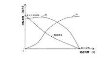
図7において、曲線Sは、多孔体Pの含水量の経時変化を示すものである。多孔体Pに含まれる液水は、徐々に蒸発していくので、多孔体Pの含水率Sが経過時間に伴って減少することが分かる。また、曲線Aは酸素の移動速度の経時変化を示している。なお、曲線Bは水蒸気の移動速度の経時変化を示している。
Next, the measuring method by the oxygen diffusion coefficient measuring apparatus of the porous body P shown in FIG. 6 will be described with reference to FIGS.
In FIG. 7, the curve S shows the change with time of the water content of the porous body P. Since the liquid water contained in the porous body P gradually evaporates, it can be seen that the moisture content S of the porous body P decreases with the passage of time. Curve A shows the change over time in the oxygen transfer rate. Curve B shows the change over time in the moving speed of water vapor.

初期状態では、上述したように、多孔体Pの含水率Sが100%であり、多孔体Pの細孔が液水で占められているので、多孔体P内を酸素が透過することはない。よって、図7の曲線Aに示すように、経過時間が0のときの酸素の移動速度は0である。このとき、図6に示す酸素センサー1では酸素が検出されず、演算装置23では、図8に示すように、多孔体の酸素拡散係数の値が0と算出される。  In the initial state, as described above, the moisture content S of the porous body P is 100%, and the pores of the porous body P are occupied by liquid water, so that oxygen does not permeate through the porous body P. . Therefore, as shown by a curve A in FIG. 7, the oxygen moving speed when the elapsed time is zero is zero. At this time, oxygen is not detected by theoxygen sensor 1 shown in FIG. 6, and the value of the oxygen diffusion coefficient of the porous body is calculated as 0 by thearithmetic unit 23 as shown in FIG.

その後、図6に示す密閉容器22の内部の温度や湿度を調整し、多孔体Pに含浸させた液水を蒸発させるようにすると、その液水が水蒸気となって多孔体Pの外部に移動していき、多孔体P内の細孔が酸素の通り道となる。これにより、図7の曲線Aに示すように、酸素の移動速度の値が徐々に大きくなっていく。このとき、図6の矢印Cに示すように、空気中に含まれる酸素は、多孔体ホルダー4に保持された多孔体Pの上面側に移動し、多孔体Pの内部を通過して電解液ケース2側に拡散していく。このような多孔体Pの酸素拡散係数を、演算装置23で継続的に算出する。  After that, when the temperature and humidity inside the sealedcontainer 22 shown in FIG. 6 are adjusted and the liquid water impregnated in the porous body P is evaporated, the liquid water becomes steam and moves to the outside of the porous body P. Thus, the pores in the porous body P become oxygen passages. As a result, as shown by a curve A in FIG. 7, the value of the oxygen moving speed gradually increases. At this time, as shown by an arrow C in FIG. 6, oxygen contained in the air moves to the upper surface side of the porous body P held by theporous body holder 4, passes through the inside of the porous body P, and passes through the electrolyte solution. It spreads to thecase 2 side. The oxygen diffusion coefficient of such a porous body P is continuously calculated by thearithmetic device 23.

そして、このまま時間が経過すると、多孔体Pに含浸させた液水がさらに蒸発する。これにより、多孔体Pの細孔内に占める液水の量がさらに少なくなって酸素の通り道が多く形成されるので、図7の曲線Aに示すように、酸素の移動速度の値はさらに増大する。このときの多孔体Pの酸素拡散係数についても、演算装置23で継続的に算出する。
このような多孔体Pの含水率Sと、演算装置23で算出した酸素拡散係数との関係を表すグラフを図8に示す。図8において、多孔体Pの含水率Sは、時間経過に伴って減少していくのに対して、演算装置23で算出される多孔体Pの酸素拡散係数の値は、時間経過に伴って増加していく。この図8に示す測定結果のグラフから、多孔体Pの含水率Sに対する酸素拡散係数を求めることができる。
And if time passes as it is, the liquid water which impregnated the porous body P will further evaporate. As a result, the amount of liquid water occupied in the pores of the porous body P is further reduced and more oxygen passages are formed, so that the value of the oxygen moving speed is further increased as shown by the curve A in FIG. To do. The oxygen diffusion coefficient of the porous body P at this time is also continuously calculated by thecalculation device 23.
A graph showing the relationship between the moisture content S of the porous body P and the oxygen diffusion coefficient calculated by thearithmetic device 23 is shown in FIG. In FIG. 8, the moisture content S of the porous body P decreases with time, whereas the oxygen diffusion coefficient value of the porous body P calculated by thearithmetic unit 23 increases with time. It will increase. From the graph of the measurement result shown in FIG. 8, the oxygen diffusion coefficient with respect to the moisture content S of the porous body P can be obtained.

以上に説明したように、本実施形態によれば、酸素センサー1は、電解液ケース2の電解液収容空間2aが密封されるので、電解液収容空間2a内の電解液の量が増減しなくなり、多孔体Pの酸素拡散係数を測定している途中で、陽極9および陰極11の表面と、電解液との接触面積が一定に維持され、多孔体Pの酸素拡散係数を高精度に測定することができる。  As described above, according to the present embodiment, theoxygen sensor 1 is sealed in the electrolytesolution storage space 2a of theelectrolyte solution case 2, so that the amount of the electrolyte solution in the electrolytesolution storage space 2a does not increase or decrease. In the course of measuring the oxygen diffusion coefficient of the porous body P, the contact area between the surfaces of the anode 9 and thecathode 11 and the electrolytic solution is kept constant, and the oxygen diffusion coefficient of the porous body P is measured with high accuracy. be able to.

また、電解液ケース2に収容された電解液が吸水することもないので、測定対象となる多孔体Pに含まれた液水を蒸発させたときでも、それに影響されずに、多孔体Pの含水量に対する酸素拡散係数を高精度に測定することができる。  Moreover, since the electrolyte solution accommodated in theelectrolyte solution case 2 does not absorb water, even when the liquid water contained in the porous material P to be measured is evaporated, the porous material P is not affected by it. The oxygen diffusion coefficient relative to the water content can be measured with high accuracy.

多孔体の酸素拡散係数測定装置を構成している酸素センサーの斜視図である。It is a perspective view of the oxygen sensor which comprises the oxygen diffusion coefficient measuring apparatus of a porous body.図1に示す酸素センサーの構造を示す分解図である。It is an exploded view which shows the structure of the oxygen sensor shown in FIG.電解液ケースの電解液収納空間に導体を収容する状態を示す拡大図である。It is an enlarged view which shows the state which accommodates a conductor in the electrolyte solution storage space of electrolyte solution case.電解液ケースの電解液注入口に外蓋を取付ける前の状態を示す斜視図である。It is a perspective view which shows the state before attaching an outer cover to the electrolyte solution injection port of an electrolyte solution case.電解液注入口に二重蓋を取付けた状態を示す斜視断面図である。It is a perspective sectional view showing the state where the double lid was attached to the electrolyte solution inlet.本発明による多孔体の酸素拡散係数測定装置の全体構成を示す説明図である。It is explanatory drawing which shows the whole structure of the oxygen diffusion coefficient measuring apparatus of the porous body by this invention.多孔体の含水率と水蒸気及び酸素との移動速度の関係を示すグラフである。It is a graph which shows the relationship between the moisture content of a porous body, and the moving speed of water vapor | steam and oxygen.多孔体の含水率に対する酸素拡散係数を示すグラフである。It is a graph which shows the oxygen diffusion coefficient with respect to the moisture content of a porous body.

符号の説明Explanation of symbols

1…酸素センサー,2…電解液ケース,2a…電解液収納空間,2b…電解液注入口,2c…段差部,2d…導線取出し孔,2e…ねじ孔,3…蓋部材,3a…ねじ,4…多孔体ホルダー,5…アダプタ,6…内蓋,6a…ねじ,6b…貫通孔,7…外蓋,7a…ねじ,8…第1の導体,9…陽極,10…第2の導体,11…陰極,12…酸素交換膜,13…Oリング,14…酸素フィルタ,15…Oリング,23…演算装置,P…多孔体  DESCRIPTION OFSYMBOLS 1 ... Oxygen sensor, 2 ... Electrolyte case, 2a ... Electrolyte storage space, 2b ... Electrolyte injection port, 2c ... Step part, 2d ... Conductor extraction hole, 2e ... Screw hole, 3 ... Lid member, 3a ... Screw, DESCRIPTION OFSYMBOLS 4 ... Porous body holder, 5 ... Adapter, 6 ... Inner lid, 6a ... Screw, 6b ... Through-hole, 7 ... Outer lid, 7a ... Screw, 8 ... First conductor, 9 ... Anode, 10 ... Second conductor , 11 ... cathode, 12 ... oxygen exchange membrane, 13 ... O-ring, 14 ... oxygen filter, 15 ... O-ring, 23 ... arithmetic unit, P ... porous body

Claims (5)

Translated fromJapanese
測定対象となる多孔体の酸素拡散係数を、ガルバニ電池式の酸素センサーを用いて測定する多孔体の酸素拡散係数測定装置であって、
前記酸素センサーは、
両端部が開口する筒状の電解液収納空間を有すると共に、この電解液収納空間の中間部に連通する電解液注入口を有する電解液ケースと、
前記電解液収納空間の一端側の開口部を覆うように押圧固定されて当該開口部を密閉する平板状の陽極と、
前記陽極の全周を押圧固定する蓋部材と、
前記電解液収納空間の他端側の開口部を覆うように押圧固定されて当該開口部を密閉する平板状の陰極と、
前記陰極の全周を押圧固定すると共に、前記陰極の外側に前記多孔体を保持可能な多孔体ホルダーと、
前記電解液注入口を密閉する二重蓋と、
を含んで構成されることを特徴とする多孔体の酸素拡散係数測定装置。
A porous oxygen diffusion coefficient measuring device for measuring the oxygen diffusion coefficient of a porous body to be measured using a galvanic cell type oxygen sensor,
The oxygen sensor is
An electrolytic solution case having a cylindrical electrolytic solution storage space that is open at both ends, and an electrolytic solution inlet that communicates with an intermediate portion of the electrolytic solution storage space;
A plate-like anode that is pressed and fixed so as to cover the opening on one end side of the electrolytic solution storage space, and seals the opening;
A lid member that presses and fixes the entire circumference of the anode;
A flat cathode that is pressed and fixed so as to cover the opening on the other end side of the electrolytic solution storage space and seals the opening;
While pressing and fixing the entire circumference of the cathode, a porous body holder capable of holding the porous body outside the cathode,
A double lid that seals the electrolyte inlet;
A device for measuring the oxygen diffusion coefficient of a porous body, comprising:
前記陽極及び前記陰極にそれぞれ接続されて、外部に電気信号を出力する導体を備え、
前記各導体は、前記陽極又は前記陰極と共に全周で押圧固定されて前記陽極又は前記陰極の周縁部に密着する環状部と、この環状部の一部から外方へ延びる導線部とを含んで構成されることを特徴とする請求項1に記載の多孔体の酸素拡散係数測定装置。
A conductor that is connected to each of the anode and the cathode and outputs an electrical signal to the outside;
Each of the conductors includes an annular portion that is pressed and fixed with the anode or the cathode along the entire circumference and closely contacts the peripheral edge of the anode or the cathode, and a conductor portion that extends outward from a part of the annular portion. The porous oxygen diffusion coefficient measuring device according to claim 1, which is configured.
前記蓋部材及び前記多孔体ホルダーは、前記電解液ケースの電解液収納空間の開口部にそれぞれ嵌合した状態で、ねじで締め付けて固定することを特徴とする請求項1又は請求項2に記載の多孔体の酸素拡散係数測定装置。  The said cover member and the said porous body holder are clamped and fixed with a screw in the state each fitted to the opening part of the electrolyte solution storage space of the said electrolyte solution case, The fixed structure of Claim 1 or Claim 2 characterized by the above-mentioned. For measuring oxygen diffusion coefficient of porous materials. 前記二重蓋は、前記電解液ケースの電解液注入口に取付けられる内蓋と、この内蓋に形成された連通孔を塞ぐ外蓋とで構成されることを特徴とする請求項1〜請求項3のいずれか一つに記載の多孔体の酸素拡散係数測定装置。  The said double lid | cover is comprised by the inner lid | cover attached to the electrolyte solution injection port of the said electrolyte solution case, and the outer lid | cover which block | closes the communicating hole formed in this inner lid | cover. The oxygen diffusion coefficient measurement apparatus for a porous body according to any one of the above. 前記外蓋は、ねじで締め付けて前記内蓋に固定することを特徴とする請求項4に記載の多孔体の酸素拡散係数測定装置。  5. The oxygen diffusion coefficient measuring apparatus for a porous body according to claim 4, wherein the outer lid is fastened with screws and fixed to the inner lid.
JP2006105164A2006-04-062006-04-06 Device for measuring oxygen diffusion coefficient of porous materialPendingJP2007278826A (en)

Priority Applications (1)

Application NumberPriority DateFiling DateTitle
JP2006105164AJP2007278826A (en)2006-04-062006-04-06 Device for measuring oxygen diffusion coefficient of porous material

Applications Claiming Priority (1)

Application NumberPriority DateFiling DateTitle
JP2006105164AJP2007278826A (en)2006-04-062006-04-06 Device for measuring oxygen diffusion coefficient of porous material

Publications (1)

Publication NumberPublication Date
JP2007278826Atrue JP2007278826A (en)2007-10-25

Family

ID=38680420

Family Applications (1)

Application NumberTitlePriority DateFiling Date
JP2006105164APendingJP2007278826A (en)2006-04-062006-04-06 Device for measuring oxygen diffusion coefficient of porous material

Country Status (1)

CountryLink
JP (1)JP2007278826A (en)

Cited By (2)

* Cited by examiner, † Cited by third party
Publication numberPriority datePublication dateAssigneeTitle
JP2013033016A (en)*2011-06-292013-02-14Nippon Soken IncDevice and method for measuring oxygen diffusion coefficient
WO2013133238A1 (en)2012-03-082013-09-12日産自動車株式会社Electrolyte film - electrode assembly

Cited By (3)

* Cited by examiner, † Cited by third party
Publication numberPriority datePublication dateAssigneeTitle
JP2013033016A (en)*2011-06-292013-02-14Nippon Soken IncDevice and method for measuring oxygen diffusion coefficient
WO2013133238A1 (en)2012-03-082013-09-12日産自動車株式会社Electrolyte film - electrode assembly
US9601793B2 (en)2012-03-082017-03-21Nissan Motor Co., Ltd.Electrolyte film—electrode assembly

Similar Documents

PublicationPublication DateTitle
US9151729B2 (en)Carbon monoxide sensor system
US5830337A (en)Electrochemical gas sensor
US3429796A (en)Gas analyzer
US11740216B2 (en)Method and apparatus for measuring humidity using an electrochemical gas sensor
JP4915903B2 (en) Method and apparatus for measuring oxygen diffusion coefficient of porous material
US11231389B2 (en)Method and apparatus for electrolyte concentration measurement in an electrochemical sensor
KR20160147881A (en) Electrochemical cell
CN114778647B (en) Method and device for measuring electrolyte concentration
US5336390A (en)Electrochemical gas sensor with disk-shaped electrodes, which are also electrical contact leads
JP2005134248A (en)Electrochemical gas sensor
JP4251970B2 (en) Gas sensor
JP4248475B2 (en) Ionic liquid electrolyte gas sensor
US3258415A (en)Oxygen analyzer and oxygen-depolarized cell therefor
JP2007278826A (en) Device for measuring oxygen diffusion coefficient of porous material
KR20060042476A (en) Reference electrode member for 3-electrode electrode potential measurement
JP3164255B2 (en) Electrochemical gas detector
CN222733566U (en)Monopole piece detection device
JP2014199235A (en)Electrochemical gas sensor
JP2006317404A (en)Electrochemical gas sensor and its manufacturing method
US20030042138A1 (en)Gas sensor
JP2003021616A (en) Hydrogen gas concentration detector
CN113358718A (en)Integrated electrochemical gas sensor
JP2003149191A (en)Gas sensor
EP1288655A2 (en)Gas sensor
JP2003028832A (en) Gas concentration detector

[8]ページ先頭

©2009-2025 Movatter.jp