JP2007273110A - Flat battery - Google Patents
Flat batteryDownload PDFInfo
- Publication number
- JP2007273110A JP2007273110AJP2006093719AJP2006093719AJP2007273110AJP 2007273110 AJP2007273110 AJP 2007273110AJP 2006093719 AJP2006093719 AJP 2006093719AJP 2006093719 AJP2006093719 AJP 2006093719AJP 2007273110 AJP2007273110 AJP 2007273110A
- Authority
- JP
- Japan
- Prior art keywords
- positive electrode
- electrode material
- negative electrode
- gasket
- dimension
- Prior art date
- Legal status (The legal status is an assumption and is not a legal conclusion. Google has not performed a legal analysis and makes no representation as to the accuracy of the status listed.)
- Pending
Links
Images


Classifications
- Y02E60/12—
Landscapes
- Sealing Battery Cases Or Jackets (AREA)
- Primary Cells (AREA)
- Battery Electrode And Active Subsutance (AREA)
Abstract
Translated fromJapaneseDescription
Translated fromJapanese本発明は、ボタン型電池やコイン型電池などの扁平形電池に関する。 The present invention relates to flat batteries such as button batteries and coin batteries.
特許文献1〜3には、上向きに開口する正極缶と下向きに開口する負極缶とからなる電池缶と、正極材の上側にセパレータを介して負極材を配する発電要素と、正極缶と負極缶との周縁間に配されて正極缶と負極缶とを絶縁するガスケットとを有していて、電池缶の内部に発電要素を収容した状態で、ガスケットによって正極缶と負極缶との間を封止する扁平形電池が開示されている。 In Patent Documents 1 to 3, a battery can comprising a positive electrode can opened upward and a negative electrode can opened downward, a power generation element in which a negative electrode material is arranged on the upper side of the positive electrode material via a separator, a positive electrode can and a negative electrode It has a gasket that is arranged between the periphery of the can and insulates the positive electrode can and the negative electrode can, and in the state where the power generation element is accommodated inside the battery can, the gap between the positive electrode can and the negative electrode can is defined by the gasket. A flat battery for sealing is disclosed.
特許文献1〜3の電池では、製造誤差による位置ずれや使用時の衝撃などで正極材が、正極缶の底壁の中心部から横方向にずれることがある。この場合、セパレータが、正極材と電池缶の内面との間に強く挟まれて破れるおそれがある。このセパレータの破損によって、負極材や負極缶の内面と正極材とが短絡して電池の破損などを招くおそれがある。 In the batteries of Patent Documents 1 to 3, the positive electrode material may be displaced laterally from the center portion of the bottom wall of the positive electrode can due to misalignment due to manufacturing errors or impact during use. In this case, the separator may be strongly sandwiched between the positive electrode material and the inner surface of the battery can and may be broken. Due to the breakage of the separator, the inner surface of the negative electrode material or the negative electrode can and the positive electrode material may be short-circuited to cause damage to the battery.
また、前記電池では、使用時の放電に伴って負極材の体積が徐々に減るとともに正極材の体積が徐々に増加する。この正極材の体積増加に応じてセパレータが負極缶側に徐々に上昇し、これによってセパレータが正極材と電池缶の内面との間に強く挟まれて破れるおそれがある。この場合も、負極材や負極缶の内面と正極材とが短絡するおそれがある。 Further, in the battery, the volume of the negative electrode material gradually decreases and the volume of the positive electrode material gradually increases with discharge during use. As the volume of the positive electrode material increases, the separator gradually rises toward the negative electrode can, which may cause the separator to be strongly sandwiched between the positive electrode material and the inner surface of the battery can and torn. In this case as well, the negative electrode material or the inner surface of the negative electrode can and the positive electrode material may be short-circuited.
そこで本発明の目的は、衝撃や放電に伴う正極材の体積増加などによって、セパレータが正極材と電池缶の内面との間に強く挟まれて破損することを防止できる扁平形電池を提供することにある。 Accordingly, an object of the present invention is to provide a flat battery capable of preventing the separator from being strongly sandwiched between the positive electrode material and the inner surface of the battery can due to an increase in volume of the positive electrode material due to impact or discharge. It is in.
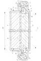
本発明が対象とする扁平形電池は、図1に示すごとく、上向きに開口する正極缶3と下向きに開口する負極缶5とからなる電池缶1と、正極材7の上側にセパレータ10を介して負極材9を配する発電要素2と、正極缶3と負極缶5との周縁間に配されて正極缶3と負極缶5とを絶縁するガスケット6とを有していて、電池缶1の内部に発電要素2を収容した状態で、ガスケット6によって正極缶3と負極缶5との間を封止するようになっている。ここでの扁平形電池は、ボタン型電池やコイン型電池などの他、扁平四角形状の電池なども含まれる。 As shown in FIG. 1, a flat battery targeted by the present invention includes a battery can 1 composed of a positive electrode can 3 that opens upward and a negative electrode can 5 that opens downward, and a
本発明は、負極缶5の上壁側に設けた収容部21に負極材9を収容しており、正極缶3の底壁12の中央側を下向きに膨出させて、正極缶3の内面側に凹部13を段落ち状に形成してあって、凹部13で正極材7を受け止めており、ガスケット6は、正極材7の周側面に対して直接に臨む規制面32を正極材7の周側面の周方向に形成して、規制面32で正極材7の横方向の移動を規制しており、規制面32の内法寸法D2が、収容部21の内法寸法D1よりも小さくなるよう設定してあることを特徴とする。 In the present invention, the negative electrode material 9 is accommodated in the
ガスケット6の規制面32が正極材7の周側面に対して直接に臨む場合としては、ガスケット6の規制面32と正極材7の周側面とが互いに密着している場合や、規制面32と正極材7の周側面とが、セパレータ10の周縁部が入り込まない程度の隙間を介して臨んでいる場合などが含まれている。 As the case where the
収容部21の内法寸法D1としては、ボタン型電池の場合には、円柱状の収容部21の内径寸法が該当し、規制面32の内法寸法D2としては、円環状のガスケット6の規制面32の内径寸法が該当する。扁平四角形状の電池の場合には、規制面32の前後および左右の内法寸法D2が、収容部21の前後および左右の内法寸法D1よりもそれぞれ小さくなるよう設定することになる。 In the case of a button type battery, the inner dimension D1 of the
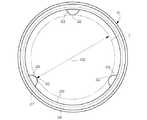
ガスケット6の規制面32は、図5に示すごとく、正極材7の周方向に対して分散した状態で形成されているものとすることができる。ここでの規制面32の内法寸法D2は、ガスケット6において各規制面32よりも内側であって、正極材7が嵌まり込むことができる領域(図5の二点鎖線のほぼ内側)の内法寸法が該当する。規制面32は、正極材7の横方向の移動を規制できる程度に分散されているものであればよく、その規制面32の分散数は、任意の個数(例えば3個)に設定できる。また、各規制面32は、一定間隔で形成してもよく、間隔を異ならせて形成してもよい。 As shown in FIG. 5, the
具体的には、ガスケット6の規制面32の内法寸法D2が、負極缶5の収容部21の内法寸法D1よりも少なくともセパレータ10の厚さ寸法の2倍分だけ小さくなるよう設定してある。言い換えると、規制面32の内法寸法D2と、収容部21の内法寸法D1との比(D2/D1)が、0.80〜0.98になるよう設定してある。 Specifically, the internal dimension D2 of the
正極材7の外法寸法は、規制面32の内法寸法D2の0.7〜0.9倍に設定されていることが好ましい。正極材7は、その外周面に装着される正極リング11を含んでいるものとすることができる。正極材7は、正極活物質として二酸化マンガンを含有するものとすることができる。正極リング11は、平面視で円形状の場合や四角形状の場合などが含まれる。正極リング11は、導電性を有する金属などからなる場合と、絶縁性のプラスチックなどからなる場合とが含まれる。 The outer dimension of the
本発明によれば、正極缶3の底壁12に凹部13を設けることで、電池内圧が異常上昇したときの正極缶3の下向きの膨張変形を凹部13のみで受け止めて、正極缶3の底壁12の周縁側である封止壁部15などの過度の変形を抑え、負極缶5と正極缶3との間での密封性の低下を抑えることができる。 According to the present invention, by providing the
そのうえで、ガスケット6の規制面32で正極材7の横方向の移動を規制して、正極材7が凹部13内で位置ずれしないようにし、かつ規制面32の内法寸法D2を負極缶5の収容部21の内法寸法D1よりも小さくしたので、製造誤差や衝撃などで正極材7が正極缶3の底壁12の周縁側にずれてセパレータ10が正極材7と電池缶1の内面との間に強く挟まれてしまうことがなく、また放電に伴う正極材7の体積増加でセパレータ10が負極缶5側に徐々に上昇しても、セパレータ10が正極材7と電池缶1の内面との間に強く挟まれてしまうことがない。これによって、セパレータ10が破断することを確実に防止でき、セパレータ10の破断で負極材9や負極缶5の内面と、正極材7とが短絡して電池が破損することなどを確実に防止できる。 In addition, the movement of the
しかも、規制面32が正極材7の周側面に対して直接に臨むので、セパレータ10によるガスケット6の過度の変形を防止できる。つまり、ガスケット6の規制面32と正極材7の周側面との間に、例えば特許文献2のようにセパレータ10の周縁部が入り込むと、そのセパレータ10は、薄手の不織布などからなって周縁部に皺などが生じ易いために、その皺によってセパレータ10の周縁部の一部が重なり合って厚くなる。 In addition, since the
その厚くなったセパレータ10の周縁部の一部でガスケット6が過度に変形して、ガスケット6による正極材7の横方向の移動の規制が不十分になったり、負極缶5と正極缶3との間での密封性の低下を招いたりするおそれがある。本発明は、規制面32が正極材7の周側面に対して直接に臨むことで、ガスケット6の変形を抑えて、前記正極材7の横方向の移動を確実に規制できるとともに、負極缶5と正極缶3との間での密封性を確実に担保できる。 The gasket 6 is excessively deformed at a part of the peripheral portion of the thickened
ガスケット6の規制面32が正極材7の周方向に対して分散していると、電池缶1内の容量の低下をできる限り抑えることができながら、セパレータ10が破断することを確実に防止できる。 When the regulating
正極材7が正極リング11を含んでいると、セパレータ10が正極リング11と電池缶1の内面との間に挟まれたときには、正極リング11が比較的硬いためにセパレータ10が破断し易くなるが、この場合にも、本発明によってセパレータ10の破断を確実に防ぐことができる。 When the
特に、正極材7は、正極活物質として二酸化マンガンを含有すると脆くなるために正極リング11を含むことが好ましく、この場合でもセパレータ10の破断を確実に防ぐことができる。 In particular, the
(実施例1) 図1および図2は、本発明が対象とする扁平形電池の実施例1を示している。電池缶1は、図1に示すごとく、上向きに開口する正極缶3と下向きに開口する負極缶5とからなって、全体が扁平なコイン形状に形成される。電池缶1の内部には、発電要素2が収容されており、正極缶3と負極缶5との周縁間には、円環状のガスケット6が配されている。Example 1 FIGS. 1 and 2 show Example 1 of a flat battery targeted by the present invention. As shown in FIG. 1, the battery can 1 includes a positive electrode can 3 that opens upward and a negative electrode can 5 that opens downward, and is formed into a flat coin shape as a whole. A
そして、電池缶1の内部に発電要素2を収容した状態で、負極缶5がガスケット6と共に正極缶3の開口内縁にかしめ固定されることで、ガスケット6によって正極缶3と負極缶5との間が密封(封止)される。また、ガスケット6によって正極缶3と負極缶5とが絶縁される。電池缶1の外径寸法は24.5mm、全厚寸法は5.0mmである。 Then, the negative electrode can 5 is caulked and fixed to the opening inner edge of the positive electrode can 3 together with the gasket 6 in a state where the
発電要素2は、正極活物質などを円盤形状に固めた正極材7と、負極活物質の金属リチウムまたはリチウム合金を円盤形状に形成した負極材9と、不織布製のセパレータ10と、非水電解質とを含み、正極材7の上側にセパレータ10を介して負極材9が配される。正極材7は、その外周面に装着される正極リング11を含んでいる。正極リング11は、導電性を有するステンレス鋼で形成される。 The
電池組み立て前のブランク状態の正極缶3は、図2に示すごとく、丸皿形状のプレス成形品からなる。正極缶3は、その底壁12の中央側を下向きに膨出させて、正極材7を受け止めるための凹部13を正極缶3の内面側に段落ち状に形成してある。正極缶3の底壁12の周縁側には、ガスケット6の下面に密着する封止壁部15が形成されており、封止壁部15の外周縁に連続して円筒状の周壁16が立ち上げ形成されている。 As shown in FIG. 2, the positive electrode can 3 in a blank state before battery assembly is formed of a round dish-shaped press-formed product. In the positive electrode can 3, the center side of the
前記凹部13を設けることによって、電池内圧が異常上昇したときの正極缶3の下向きの膨張変形を凹部13のみで受け止めて、封止壁部15が過度に変形して、ガスケット6の下面と封止壁部15との間での密着性が低下することを抑えている。 By providing the
正極リング11は、上下が開口していて正極材7の周側面を形成する円筒部19と、円筒部19の下端から内方へ水平状に延びる円環形状のフランジ部20とを有する。円筒部19の上下高さ寸法は、正極材7全体の上下高さ寸法よりも僅かに小さい。円筒部19の上下高さ寸法と、正極材7全体の上下高さ寸法とは等しくてもよい。円筒部19の上面が開口しているので、正極材7は放電時に上方へ自由に膨張できる。 The
負極缶5は、丸皿形状のプレス成形品からなり、その上壁側に設けられる負極材収容用の収容部21と、収容部21の下端の肩部から外向きに張り出されるフランジ壁22と、フランジ壁22に連続して下向きに突出する封止部23とを一体に有している。封止部23は、はぜ折りされた内外二重の壁で形成してある。 The negative electrode can 5 is made of a round plate-shaped press-molded product, and includes a
ガスケット6は、ポリプロピレン樹脂やポリフェニレンサルファイド樹脂やテトラフルオロエチレン−パーフルオロアルコキシエチレン共重合体などの弾性と絶縁性とに優れたプラスチック材を素材とする射出成形品からなる。 The gasket 6 is made of an injection-molded product made of a plastic material excellent in elasticity and insulation, such as polypropylene resin, polyphenylene sulfide resin, and tetrafluoroethylene-perfluoroalkoxyethylene copolymer.
ガスケット6は、リング形状のベース部26と、ベース部26の外周縁から上向きに張り出して正極缶3の周壁16と負極缶5の封止部23との間に挟持される外筒壁27と、ベース部26の内周縁から上向きに張り出す内筒壁29と、ベース部26の内周縁から内方へ延びる規制壁31とを有する。 The gasket 6 includes a ring-shaped
規制壁31は、その内周面(規制面)32が正極リング11を含む正極材7の周側面に臨んでいる。つまり、規制壁31の規制面32は、正極リング11を含む正極材7の周側面を周方向に囲むように円環状に形成してあり、かつ凹部13の周縁よりも内方(正極缶3の中心側)に位置している。前記規制面32によって正極材7の横方向の移動が規制される。規制壁31の上下厚さ寸法は、0.25〜1.5mm程度に設定される。 The
正極材7は、正極活物質として二酸化マンガンを含有しており、この二酸化マンガンに、黒鉛、テトラフルオロエチレン−ヘキサフルオロプロピレン共重合体およびヒドロキシプロピルセルロースを混合して正極合剤を調整し、所定の金型内に正極リング11をセットしたのちに、前記正極合剤を充填して加圧成形し、この成形体を加熱して円盤状に形成する。 The
セパレータ10は、ポリブチレンテレフタレート繊維を素材とする不織布を使用しており、非水電解質を含浸させている。非水電解質としては、プロピレンカーボネイトと1,2−ジメトキシエタンとを混合した溶媒にLiClO4 を溶解した溶液を用いた。セパレータ10の厚さ寸法は0.3〜0.4mm程度である。The
負極材9は、図1に示すごとく、その直径寸法(外法寸法)が負極缶5の収容部21の内径寸法(内法寸法)D1よりも小さく設定される。正極リング11を含む正極材7は、直径寸法(外法寸法)が負極材9の直径寸法よりも小さく、かつガスケット6の規制面32の内径寸法(内法寸法)D2よりも僅かに小さく設定される。つまり、正極リング11を含む正極材7の直径寸法は、規制面32の内径寸法D2に対して0.7〜0.9倍程度に設定される。 As shown in FIG. 1, the negative electrode material 9 is set to have a diameter dimension (external dimension) smaller than an inner diameter dimension (internal dimension) D <b> 1 of the
規制面32の内径寸法D2は、負極缶5の収容部21の内径寸法D1よりも少なくともセパレータ10の厚さ寸法(0.3〜0.4mm)の2倍分だけ小さくなるよう設定してある。すなわち、規制面32の内径寸法D2は、収容部21の内径寸法D1よりも0.6〜0.8mm程度だけ小さくなる。具体的には、規制面32の内径寸法D2と、収容部21の内径寸法D1との比(D2/D1)は0.80〜0.98に設定される。 The inner diameter dimension D2 of the
扁平形電池の組み立てに際しては、図1とは天地を逆姿勢にした状態で組み立てる。正極材7は、前述のごとく正極リング11内に装填しておく。そして、負極缶5の開口端部にガスケット6を装着し、負極缶5の収容部21の内面に負極材9を導電性接着剤などで固定したのちに、セパレータ10および正極材7を負極材9の上側に重ねるように組み付ける。 When assembling the flat battery, the battery is assembled in a state where the top and bottom of FIG. The
次に、負極缶5内に非水電解液を注入したうえで、正極缶3を上方より被せて負極缶5とガスケット6とを正極缶3内に嵌め込み、正極缶3の周壁16の開口端部を内方に向けてかしめ加工する。これによって電池の組み立てが完了する。この状態で、正極リング11を含む正極材7の下端が凹部13内に嵌まり込んでいる(図1の状態)。 Next, after injecting a non-aqueous electrolyte into the negative electrode can 5, the positive electrode can 3 is covered from above and the negative electrode can 5 and the gasket 6 are fitted into the positive electrode can 3, and the open end of the
正極缶3と負極缶5との周縁間にガスケット6が圧縮状態で挟み込まれることで、電池缶1内が密封される。正極材7および正極リング11の下面は、正極缶5の凹部13の内面に接していて、正極材7が正極缶3に導通している。 The gasket 6 is sealed between the positive electrode can 3 and the negative electrode can 5 so that the inside of the battery can 1 is sealed. The lower surfaces of the
ガスケット6の規制面32によって正極材7が正極缶3の底壁12のほぼ中央に位置決めされ、かつD2/D1が0.80〜0.98の範囲内に設定されるので、正極リング11を含む正極材7と、電池缶1の内面との間にセパレータ10が挟み込まれることがない。 The
(実施例2) 図3は、実施例2に係る扁平形電池を示している。実施例2では、ガスケット6の内筒壁29が、ベース部26の内周縁から内方へ延びる規制壁31の内周縁から上向きに張り出しており、その内筒壁29の内周面で前記規制面32を形成してある。その他の点は、実施例1と同じであるので説明を省略する。Example 2 FIG. 3 shows a flat battery according to Example 2. In the second embodiment, the inner
実施例2でも、規制面32によって正極材7が正極缶3の底壁12のほぼ中央に位置決めされ、規制面32の内径寸法D2と、収容部21の内径寸法D1との比(D2/D1)が0.80〜0.98に設定されている。 Also in the second embodiment, the
(実施例3) 図4は、実施例3に係る扁平形電池を示している。実施例3では、ガスケット6の内筒壁29が、ベース部26の内周縁から内方へ延びる規制壁31の内周縁から下向きに張り出しており、その内筒壁29の内周面で前記規制面32を形成してある。その他の点は、実施例1と同じであるので説明を省略する。Example 3 FIG. 4 shows a flat battery according to Example 3. In the third embodiment, the inner
実施例3でも、規制面32によって正極材7が正極缶3の底壁12のほぼ中央に位置決めされ、規制面32の内径寸法D2と、収容部21の内径寸法D1との比(D2/D1)が0.80〜0.98に設定されている。 Also in the third embodiment, the
(実施例4) 図5は、実施例4の扁平形電池に係るガスケット6を示している。実施例4では、ガスケット6の規制壁31が、正極材7の周側面の周方向に対して分散した状態で形成されている。つまり、前記規制壁31は3個の小壁部33からなり、各小壁部33は、正極材7の周側面の周方向に対して所定間隔で設けられている。そして、各小壁部33の内周側の先端部分に形成された規制面32で、正極材7の横方向の移動が規制されるようになっている。その他の点は、実施例1と同じであるので説明を省略する。なお、図5では、小壁部33は3個だけ形成されているが、4個以上形成してもよい。Example 4 FIG. 5 shows a gasket 6 according to a flat battery of Example 4. In Example 4, the
実施例4において、各小壁部33の形成位置におけるガスケット6の縦断面は図1と同様の断面形状であってもよく、図3と同様の断面形状であってもよく、図4と同様の断面形状であってもよく、あるいはそれ以外の断面形状であってもよい。 In Example 4, the longitudinal section of the gasket 6 at the position where each
実施例1において、ガスケット6の規制壁31の上下厚さ寸法を内筒壁29の上下厚さ寸法とほぼ等しくしてもよい。前記各実施例において、正極リング11を省略した状態で、正極材7を電池缶1内に収容してもよい。 In the first embodiment, the upper and lower thickness dimension of the
1 電池缶
2 発電要素
3 正極缶
5 負極缶
7 正極材
9 負極材
10 セパレータ
11 正極リング
12 底壁
13 凹部
21 収容部
31 規制壁
32 規制面
33 小壁部DESCRIPTION OF SYMBOLS 1 Battery can 2
Claims (7)
Translated fromJapanese前記負極缶の上壁側に設けた収容部に前記負極材を収容しており、
前記正極缶の底壁の中央側を下向きに膨出させて、前記正極缶の内面側に凹部を段落ち状に形成してあって、前記凹部で前記正極材を受け止めており、
前記ガスケットは、前記正極材の周側面に対して直接に臨む規制面を前記正極材の周側面の周方向に形成して、前記規制面で前記正極材の横方向の移動を規制しており、
前記規制面の内法寸法(D2)が、前記収容部の内法寸法(D1)よりも小さくなるよう設定してあることを特徴とする扁平形電池。A battery can composed of a positive electrode can opened upward and a negative electrode can opened downward; a power generation element having a negative electrode material arranged on the upper side of the positive electrode material via a separator; and between the peripheral edges of the positive electrode can and the negative electrode can A gasket that insulates the positive electrode can and the negative electrode can, and the power generation element is housed inside the battery can, and is interposed between the positive electrode can and the negative electrode can by the gasket. In the flat battery that seals
The negative electrode material is accommodated in the accommodating portion provided on the upper wall side of the negative electrode can,
The center side of the bottom wall of the positive electrode can is bulged downward, a concave portion is formed in a stepped shape on the inner surface side of the positive electrode can, and the positive electrode material is received by the concave portion,
The gasket forms a regulating surface that directly faces the circumferential side surface of the positive electrode material in a circumferential direction of the circumferential side surface of the positive electrode material, and regulates lateral movement of the positive electrode material by the regulating surface. ,
A flat battery characterized in that an internal dimension (D2) of the regulating surface is set to be smaller than an internal dimension (D1) of the housing portion.
Priority Applications (1)
| Application Number | Priority Date | Filing Date | Title |
|---|---|---|---|
| JP2006093719AJP2007273110A (en) | 2006-03-30 | 2006-03-30 | Flat battery |
Applications Claiming Priority (1)
| Application Number | Priority Date | Filing Date | Title |
|---|---|---|---|
| JP2006093719AJP2007273110A (en) | 2006-03-30 | 2006-03-30 | Flat battery |
Publications (1)
| Publication Number | Publication Date |
|---|---|
| JP2007273110Atrue JP2007273110A (en) | 2007-10-18 |
Family
ID=38675728
Family Applications (1)
| Application Number | Title | Priority Date | Filing Date |
|---|---|---|---|
| JP2006093719APendingJP2007273110A (en) | 2006-03-30 | 2006-03-30 | Flat battery |
Country Status (1)
| Country | Link |
|---|---|
| JP (1) | JP2007273110A (en) |
Cited By (5)
| Publication number | Priority date | Publication date | Assignee | Title |
|---|---|---|---|---|
| JP2008159411A (en)* | 2006-12-25 | 2008-07-10 | Matsushita Electric Ind Co Ltd | Flat battery |
| JP2009259627A (en)* | 2008-04-17 | 2009-11-05 | Hitachi Maxell Ltd | Flat battery and tire air pressure detection sensor |
| JP2010212207A (en)* | 2009-03-12 | 2010-09-24 | Hitachi Maxell Ltd | Flat battery |
| JP2012038628A (en)* | 2010-08-09 | 2012-02-23 | Sony Corp | Nonaqueous electrolyte battery and method of manufacturing the same |
| WO2018124152A1 (en)* | 2016-12-27 | 2018-07-05 | マクセルホールディングス株式会社 | Coin-type battery and manufacturing method thereof |
- 2006
- 2006-03-30JPJP2006093719Apatent/JP2007273110A/enactivePending
Cited By (6)
| Publication number | Priority date | Publication date | Assignee | Title |
|---|---|---|---|---|
| JP2008159411A (en)* | 2006-12-25 | 2008-07-10 | Matsushita Electric Ind Co Ltd | Flat battery |
| JP2009259627A (en)* | 2008-04-17 | 2009-11-05 | Hitachi Maxell Ltd | Flat battery and tire air pressure detection sensor |
| JP2010212207A (en)* | 2009-03-12 | 2010-09-24 | Hitachi Maxell Ltd | Flat battery |
| JP2012038628A (en)* | 2010-08-09 | 2012-02-23 | Sony Corp | Nonaqueous electrolyte battery and method of manufacturing the same |
| WO2018124152A1 (en)* | 2016-12-27 | 2018-07-05 | マクセルホールディングス株式会社 | Coin-type battery and manufacturing method thereof |
| US11075420B2 (en) | 2016-12-27 | 2021-07-27 | Maxell Holdings, Ltd. | Coin-type battery and manufacturing method thereof |
Similar Documents
| Publication | Publication Date | Title |
|---|---|---|
| JP5294248B2 (en) | Flat battery | |
| CN109659454B (en) | Top cover assembly of secondary battery and secondary battery | |
| CN118213682A (en) | Top cap subassembly and secondary cell of secondary cell | |
| CN109659453B (en) | Secondary cell's top cap subassembly and secondary cell | |
| US20090186269A1 (en) | Rechargeable battery | |
| JP4453708B2 (en) | battery | |
| JP2012190758A (en) | Flat type battery | |
| JP2017157355A (en) | Electricity storage element | |
| JP2007273110A (en) | Flat battery | |
| CN213026284U (en) | Miniature lithium ion battery | |
| JP2018081780A (en) | battery | |
| JP2011187407A (en) | Flat battery and tire pressure detecting device equipped with it | |
| JP2007273109A (en) | Flat battery | |
| JP5305315B2 (en) | Flat battery | |
| JP5216964B2 (en) | Flat battery and tire pressure sensor | |
| JP2017157352A (en) | Manufacturing method of power storage element, and power storage element | |
| JP2005302625A (en) | battery | |
| JP2008218244A (en) | Batteries and medical electronic devices using the batteries | |
| JP5336230B2 (en) | Flat battery | |
| JP2011187289A (en) | Flat battery | |
| JP2007273111A (en) | Flat battery | |
| CN114284542A (en) | Battery manufacturing method and battery | |
| JP2010212207A (en) | Flat battery | |
| JP2011192391A (en) | Flat battery | |
| JP6940861B2 (en) | Flat sealed battery and gasket manufacturing method for sealed battery |
Legal Events
| Date | Code | Title | Description |
|---|---|---|---|
| A621 | Written request for application examination | Effective date:20090219 Free format text:JAPANESE INTERMEDIATE CODE: A621 | |
| A711 | Notification of change in applicant | Effective date:20110519 Free format text:JAPANESE INTERMEDIATE CODE: A712 | |
| RD02 | Notification of acceptance of power of attorney | Effective date:20110524 Free format text:JAPANESE INTERMEDIATE CODE: A7422 | |
| A131 | Notification of reasons for refusal | Free format text:JAPANESE INTERMEDIATE CODE: A131 Effective date:20120620 | |
| A02 | Decision of refusal | Effective date:20121017 Free format text:JAPANESE INTERMEDIATE CODE: A02 |