JP2007268802A - Image forming apparatus and image forming method - Google Patents
Image forming apparatus and image forming methodDownload PDFInfo
- Publication number
- JP2007268802A JP2007268802AJP2006095813AJP2006095813AJP2007268802AJP 2007268802 AJP2007268802 AJP 2007268802AJP 2006095813 AJP2006095813 AJP 2006095813AJP 2006095813 AJP2006095813 AJP 2006095813AJP 2007268802 AJP2007268802 AJP 2007268802A
- Authority
- JP
- Japan
- Prior art keywords
- liquid
- intermediate transfer
- image
- transfer member
- recording medium
- Prior art date
- Legal status (The legal status is an assumption and is not a legal conclusion. Google has not performed a legal analysis and makes no representation as to the accuracy of the status listed.)
- Pending
Links
Images


Classifications
- B—PERFORMING OPERATIONS; TRANSPORTING
- B41—PRINTING; LINING MACHINES; TYPEWRITERS; STAMPS
- B41J—TYPEWRITERS; SELECTIVE PRINTING MECHANISMS, i.e. MECHANISMS PRINTING OTHERWISE THAN FROM A FORME; CORRECTION OF TYPOGRAPHICAL ERRORS
- B41J2/00—Typewriters or selective printing mechanisms characterised by the printing or marking process for which they are designed
- B41J2/005—Typewriters or selective printing mechanisms characterised by the printing or marking process for which they are designed characterised by bringing liquid or particles selectively into contact with a printing material
- B41J2/0057—Typewriters or selective printing mechanisms characterised by the printing or marking process for which they are designed characterised by bringing liquid or particles selectively into contact with a printing material where an intermediate transfer member receives the ink before transferring it on the printing material
Landscapes
- Ink Jet (AREA)
- Ink Jet Recording Methods And Recording Media Thereof (AREA)
Abstract
Translated fromJapaneseDescription
Translated fromJapanese本発明は、画像形成装置及び画像形成方法に係り、特に、中間転写体上に形成された画像を記録媒体に転写することで記録媒体上に画像を形成する中間転写型の画像形成装置及び画像形成方法に関する。 The present invention relates to an image forming apparatus and an image forming method, and more particularly, to an intermediate transfer type image forming apparatus and an image which form an image on a recording medium by transferring the image formed on the intermediate transfer member to the recording medium. It relates to a forming method.
インクジェット記録装置として、記録ヘッド(インクジェットヘッド)によって中間転写体上に画像を形成してから、その中間転写体上に形成された画像を記録媒体に転写することで記録媒体上に画像を形成する、所謂、中間転写型の記録装置が知られている。従来、このような記録装置では、中間転写体上で高画質を得ることと、高い転写性を得ることを両立することは困難であった。なぜなら、転写剥離性の高い中間転写体は基本的に表面エネルギーの低い、撥液性の高い材質で構成されることが多く、中間転写体上で液流れが発生し、画質を低下させやすいからである。このようなことから、中間転写体上での画像品質を図る様々な方法が提案されている。 As an ink jet recording apparatus, an image is formed on an intermediate transfer member by a recording head (ink jet head), and then the image formed on the intermediate transfer member is transferred to a recording medium to form an image on the recording medium. A so-called intermediate transfer type recording apparatus is known. Conventionally, with such a recording apparatus, it has been difficult to achieve both high image quality on the intermediate transfer member and high transferability. This is because an intermediate transfer member with high transfer releasability is basically composed of a material with low surface energy and high liquid repellency, and a liquid flow is generated on the intermediate transfer member, which tends to deteriorate image quality. It is. For this reason, various methods for improving the image quality on the intermediate transfer member have been proposed.
例えば、特許文献1や特許文献2では、中間転写体の表面改質を行う方法が提案されている。特許文献1では、フッ素化合物又はシリコーン化合物の少なくとも1つの表面を有する中間転写体にプラズマ処理と界面活性剤付与処理による表面改質を施している。特許文献2では、離型性表面を有する中間転写体にエネルギー付与し、表面改質を施したものを使用している。 For example,
また、特許文献3では、色材などの溶媒不溶性材料を含む第1の液体と、第1の液体と反応性を有し凝集体を形成する第2の液体との、2種類の液体を用いる方法が提案されている。同方法によれば、記録ヘッドを用いて中間転写体上に第2の液体を付与してから第1の液体を付与する際、第2の液体付与量を第1の液体付与量よりも少なく供給することによって、中間転写体上でブリーディングやフェザリングの無い画像を形成し、中間転写体上に形成された画像を記録媒体に転写している。 In
更に、特許文献4では、中間転写体の濡れ性を向上させる第1の材料を中間転写体に付与し、インクの流動性を低下させるための第2の材料を付与し、記録ヘッドからインクを吐出し、中間転写体上に画像を形成する方法が提案されている。
しかしながら、特許文献1や特許文献2で提案される方法ではシステム負荷が大きいという問題がある。また、特許文献3で提案される方法では比較的低速なシステムでは中間転写体上での高画質化には有効であるが、高速システムの場合には、中間転写体上で第1の液体と第2の液体を混合させてから転写を行うまでの時間が極めて短いために、十分な反応が行われず、転写時にドット割れが発生し、転写後の中間転写体上に残存物が残ってしまうことが判明した。このため、中間転写体上の残存物を除去しなければならず、中間転写体表面のクリーニングに多大な負荷がかかってしまうという問題がある。更に、特許文献4で提案される方法では3材料プロセスでシステム性が悪いという問題がある。 However, the methods proposed in
本発明はこのような事情に鑑みてなされたもので、中間転写体上の画像品質を向上させると共に、中間転写体上の画像形成から記録媒体への転写を良好且つ高速に行うことのできる中間転写型の画像形成装置及び画像形成方法を提供することを目的とする。 The present invention has been made in view of such circumstances, and it is possible to improve the image quality on the intermediate transfer member, and to perform the transfer from the image formation on the intermediate transfer member to the recording medium satisfactorily and at high speed. It is an object of the present invention to provide a transfer type image forming apparatus and an image forming method.
前記目的を達成するために、請求項1に記載の発明は、中間転写体上に形成された画像を記録媒体に転写することで前記記録媒体上に画像を形成する画像形成装置であって、溶媒不溶性材料を含有する第1の液体を前記中間転写体上に付与する第1の液体付与手段と、前記溶媒不溶性材料を凝集させる機能を有する第2の液体を前記第1の液体に先立って前記中間転写体上に付与する第2の液体付与手段と、前記第1の液体を付与する際の前記中間転写体上の前記第2の液体の最小厚みが1μm以上であり、且つ、単位面積当りの前記第2の液体の付与量が単位面積あたりの前記第1の液体の付与量以上であるように制御する吐出制御手段と、を備えたことを特徴とする画像形成装置を提供する。 In order to achieve the above object, the invention according to
本発明によれば、中間転写体上の第2の液体中に第1の液体が浸る状態となり、第1の液体全体で反応が促進され、第1の液体に含有される溶媒不溶性材料を直ちに凝集させることができる。これにより、中間転写体上の画像品質が向上すると共に、高速システムを組んだ場合でも、中間転写体から記録媒体への転写を良好に行うことができる。このため、転写後の中間転写体上に残存物を残すことなく、転写後の中間転写体に対するクリーニング負荷を低減することができる。 According to the present invention, the first liquid is immersed in the second liquid on the intermediate transfer member, the reaction is accelerated in the entire first liquid, and the solvent-insoluble material contained in the first liquid is immediately removed. Can be agglomerated. As a result, the image quality on the intermediate transfer member is improved and transfer from the intermediate transfer member to the recording medium can be satisfactorily performed even when a high-speed system is assembled. For this reason, it is possible to reduce the cleaning load on the intermediate transfer member after transfer without leaving any residue on the intermediate transfer member after transfer.
本明細書において、「記録媒体」とは、一般的な装置で用いられる紙だけでなく、布、金属、板、ガラス、セラミックス、木材、プラスチックフィルム、皮革等を含む。 In this specification, the “recording medium” includes not only paper used in a general apparatus but also cloth, metal, plate, glass, ceramics, wood, plastic film, leather, and the like.
また、前記目的を達成するために、請求項2に記載の発明は、中間転写体上に形成された画像を記録媒体に転写することで前記記録媒体上に画像を形成する画像形成装置であって、溶媒不溶性材料を含有する第1の液体を前記中間転写体上に付与する第1の液体付与手段と、前記溶媒不溶性材料を凝集させる機能を有する第2の液体を前記第1の液体に先立って前記中間転写体上に付与する第2の液体付与手段と、前記第1の液体を付与する際の前記中間転写体上の前記第2の液体の最小厚みが1μm以上であり、且つ、前記第1の液体の付与領域だけでなく前記第1の液体の付与領域を囲む周辺領域にも前記第2の液体を付与する吐出制御手段と、を備えたことを特徴とする画像形成装置を提供する。 In order to achieve the above object, an invention according to claim 2 is an image forming apparatus that forms an image on the recording medium by transferring the image formed on the intermediate transfer member to the recording medium. A first liquid applying means for applying a first liquid containing a solvent-insoluble material onto the intermediate transfer member; and a second liquid having a function of aggregating the solvent-insoluble material into the first liquid. A second liquid applying means for applying the first liquid on the intermediate transfer body in advance; a minimum thickness of the second liquid on the intermediate transfer body when applying the first liquid is 1 μm or more; and An image forming apparatus comprising: an ejection control unit that applies the second liquid not only to the first liquid application region but also to a peripheral region surrounding the first liquid application region. provide.
本発明によれば、中間転写体上で第2の液体が乾燥して引けの現象が発生しても、第1の液体との反応に十分な量の第2の液体が残る。これにより、中間転写体上の画像品質が向上すると共に、高速システムを組んだ場合でも、中間転写体から記録媒体への転写を良好に行うことができる。このため、転写後の中間転写体上に残存物を残すことなく、転写後の中間転写体に対するクリーニング負荷を低減することができる。 According to the present invention, even when the second liquid dries on the intermediate transfer member and the phenomenon of a close-up occurs, a sufficient amount of the second liquid remains for reaction with the first liquid. As a result, the image quality on the intermediate transfer member is improved and transfer from the intermediate transfer member to the recording medium can be satisfactorily performed even when a high-speed system is assembled. For this reason, it is possible to reduce the cleaning load on the intermediate transfer member after transfer without leaving any residue on the intermediate transfer member after transfer.
請求項3に記載の発明は、請求項2に記載の画像形成装置であって、前記周辺領域は、前記第1の液体の付与領域を外側四方にそれぞれ少なくとも前記第1の液体によるドット径に相当する大きさだけ広げた領域であることを特徴とする。 According to a third aspect of the present invention, in the image forming apparatus according to the second aspect, in the peripheral area, the application area of the first liquid is set to at least a dot diameter of the first liquid in each of the outer four sides. It is characterized in that it is an area expanded by a corresponding size.
請求項3の態様は、中間転写体上で第2の液体が乾燥して引けの現象が発生するような場合でも良好な転写率を得ることのできる好ましい態様である。 The aspect of
請求項4に記載の発明は、請求項1乃至請求項3のいずれか1項に記載の画像形成装置であって、前記第2の液体の最大厚みが9μm以下であることを特徴とする。 A fourth aspect of the present invention is the image forming apparatus according to any one of the first to third aspects, wherein the maximum thickness of the second liquid is 9 μm or less.
請求項4の態様によれば、第1の液体の所望の拡がり率を達成することができ、画像品質が向上する。 According to the aspect of
請求項5に記載の発明は、請求項1乃至請求項4のいずれか1項に記載の画像形成装置であって、前記第2の液体の表面張力は前記第1の液体の表面張力以下であることを特徴とする。 A fifth aspect of the present invention is the image forming apparatus according to any one of the first to fourth aspects, wherein the surface tension of the second liquid is less than or equal to the surface tension of the first liquid. It is characterized by being.
請求項5の態様によれば、第2の液体は、第1の液体中の溶媒不溶性材料を凝集させる機能だけでなく、第1の液体の濡れ性を向上させる機能も有する。このため、第2の液体と反応した第1の液体の濡れ性が向上するので、第1の液体の拡がり率を1.5以上4.0以下にすることができ、中間転写体上での画像品質を向上させることができる。 According to the aspect of
請求項6に記載の発明は、請求項1乃至請求項5のいずれか1項に記載の画像形成装置であって、前記溶媒不溶性材料は色材であることを特徴とする。 A sixth aspect of the present invention is the image forming apparatus according to any one of the first to fifth aspects, wherein the solvent-insoluble material is a coloring material.
請求項7に記載の発明は、請求項1乃至請求項6のいずれか1項に記載の画像形成装置であって、前記溶媒不溶性材料は、前記記録媒体上での定着性を向上させる材料、耐擦過性を向上させる材料、又は、転写率を向上させる材料であることを特徴とする。 A seventh aspect of the present invention is the image forming apparatus according to any one of the first to sixth aspects, wherein the solvent-insoluble material is a material that improves fixability on the recording medium, It is characterized by being a material that improves scratch resistance or a material that improves the transfer rate.
また、前記目的を達成するために、請求項8に記載の発明は、中間転写体上に形成された画像を記録媒体に転写することで前記記録媒体上に画像を形成する画像形成方法であって、溶媒不溶性材料を含有する第1の液体に先立って、前記溶媒不溶性材料を凝集させる機能を有する第2の液体を前記中間転写体上に付与する工程と、前記中間転写体上に前記第1の液体を付与する工程と、を含み、前記第1の液体を付与する際の前記中間転写体上の前記第2の液体の最小厚みが1μm以上であり、且つ、単位面積当りの前記第2の液体の付与量が単位面積あたりの前記第1の液体の付与量以上であることを特徴とする画像形成方法を提供する。 In order to achieve the above object, the invention according to
また、前記目的を達成するために、請求項9に記載の発明は、中間転写体上に形成された画像を記録媒体に転写することで前記記録媒体上に画像を形成する画像形成方法であって、溶媒不溶性材料を含有する第1の液体に先立って、前記溶媒不溶性材料を凝集させる機能を有する第2の液体を前記中間転写体上に付与する工程と、前記中間転写体上に前記第1の液体を付与する工程と、を含み、前記第1の液体を付与する際の前記中間転写体上の前記第2の液体の最小厚みが1μm以上であり、且つ、前記第1の液体の付与領域だけでなく前記第1の液体の付与領域を囲む周辺領域にも前記第2の液体を付与することを特徴とする。 In order to achieve the above object, the invention according to claim 9 is an image forming method for forming an image on the recording medium by transferring the image formed on the intermediate transfer member to the recording medium. A second liquid having a function of aggregating the solvent-insoluble material on the intermediate transfer body prior to the first liquid containing the solvent-insoluble material; Applying a first liquid, and the minimum thickness of the second liquid on the intermediate transfer member when applying the first liquid is 1 μm or more, and the first liquid The second liquid is applied not only to the application region but also to a peripheral region surrounding the application region of the first liquid.
本発明によれば、中間転写体上の第2の液体中に第1の液体が浸る状態となり、第1の液体全体で反応が促進され、第1の液体に含有される溶媒不溶性材料を直ちに凝集させることができる。これにより、中間転写体上の画像品質が向上すると共に、高速システムを組んだ場合でも、中間転写体から記録媒体への転写を良好に行うことができる。このため、転写後の中間転写体上に残存物を残すことなく、転写後の中間転写体に対するクリーニング負荷を低減することができる。 According to the present invention, the first liquid is immersed in the second liquid on the intermediate transfer member, the reaction is accelerated in the entire first liquid, and the solvent-insoluble material contained in the first liquid is immediately removed. Can be agglomerated. As a result, the image quality on the intermediate transfer member is improved and transfer from the intermediate transfer member to the recording medium can be satisfactorily performed even when a high-speed system is assembled. For this reason, it is possible to reduce the cleaning load on the intermediate transfer member after transfer without leaving any residue on the intermediate transfer member after transfer.
以下、添付図面に従って本発明の好ましい実施の形態について詳説する。 Hereinafter, preferred embodiments of the present invention will be described in detail with reference to the accompanying drawings.
本発明の一実施形態のインクジェット記録装置は、2種類の液体として、色材等の溶媒不溶性材料を含有するインク(第1の液体)と、インクと反応性がありインク中の溶媒不溶性材料を凝集させる機能をもつ処理液(第2の液体)を用いて、中間転写体上に画像を形成し、中間転写体上に形成された画像を記録媒体に転写することで記録媒体上に画像を形成する、中間転写型のインクジェット記録装置である。 An ink jet recording apparatus according to an embodiment of the present invention includes an ink containing a solvent-insoluble material such as a coloring material (first liquid) as two types of liquid, and a solvent-insoluble material in the ink that is reactive with the ink. An image is formed on the intermediate transfer member by using a processing liquid (second liquid) having an aggregating function, and the image formed on the intermediate transfer member is transferred to the recording medium. This is an intermediate transfer type inkjet recording apparatus to be formed.
図1は本実施形態のインクジェット記録装置の概略構成を示した模式図である。図示するように、本実施形態のインクジェット記録装置10は、中間転写体12、処理液供給部14、マーキング部16、及び転写部18を主たる構成とし、更に、溶媒除去部20、クリーニング部22、及び画像定着部24を備えている。 FIG. 1 is a schematic diagram showing a schematic configuration of the ink jet recording apparatus of the present embodiment. As shown in the figure, the ink
中間転写体12は所定幅を有する無端状のベルトで構成され、複数のローラー26に巻き掛けられた構造となっている。本実施形態では、一例として4つのローラー26A〜26Dが用いられている。中間転写体12としてドラム状部材や板状部材を用いる態様もある。 The
複数のローラー26のうち少なくとも1つの主ローラーにはモータ(不図示)の動力が伝達され、このモータの駆動により中間転写体12が各ローラー26(26A〜26D)の外側を図1の反時計回りの方向(以下、「転写体回転方向」という。)に回転するように構成されている。 The power of a motor (not shown) is transmitted to at least one main roller among the plurality of
処理液供給部14には、処理液(S)に対応する記録ヘッド(処理液用ヘッド)30Sが設けられている。処理液用ヘッド30Sは中間転写体12に対向する吐出面から処理液を吐出する。これにより、中間転写体12の記録面12a上に処理液が付与される。 The processing
マーキング部16は、処理液供給部14の転写体回転方向下流側に配置される。マーキング部16には、ブラック(K)、シアン(C)、マゼンダ(M)、イエロー(Y)の各色インクに対応する記録ヘッド(インク用ヘッド)30K、30C、30M、30Yが設けられている。各インク用ヘッド30K、30C、30M、30Yは中間転写体12に対向する吐出面からそれぞれ対応する各色インクを吐出する。これにより、中間転写体12の記録面12a上に各色インクが付与される。 The marking
処理液用ヘッド30S、及びインク用ヘッド30K、30C、30M、30Yはいずれも、中間転写体12上に形成される画像の最大記録幅(最大記録幅)に渡って多数の吐出口(ノズル)が形成されたフルラインヘッドとなっている。中間転写体12の幅方向(図1の紙面表裏方向)に短尺のシャトルヘッドを往復走査しながら記録を行うシリアル型のものに比べて、中間転写体12に対して高速に画像記録を行うことができる。もちろん、シリアル型であっても比較的高速記録が可能な方式、例えば、1回の走査で1ラインを形成するワンパス記録方式に対しても本発明は好適である。 Each of the
本実施形態では、各記録ヘッド(処理液用ヘッド30S、及びインク用ヘッド30K、30C、30M、30Y)は全て同一構造であり、以下では、これらを代表して符号30で記録ヘッドを表すものとする。記録ヘッド30の構造については後で説明する。尚、本発明の実施に際しては、各記録ヘッドが全て同一構造である態様に限定されず、例えば、処理液用ヘッド30Sとインク用ヘッド30K、30C、30M、30Yが別構造であってもよい。 In the present embodiment, the recording heads (the
処理液用ヘッド30Sから中間転写体12に向かって処理液が吐出されると、中間転写体12の回転に伴って、中間転写体12の処理液が付与された領域は各インク用ヘッド30K、30C、30M、30Yの真下に順次移動し、各インク用ヘッド30K、30C、30M、30Yからそれぞれ対応する各色インクが吐出される。上述したように、処理液はインク中の溶媒不溶性材料(色材等)を凝集させる機能を有している。このため、中間転写体12上に付与されたインクは処理液との反応によって高粘度化し、同一色又は異なる色間のインク滴同士の着弾干渉が防止され、中間転写体12上に高品質な画像が形成される。 When the processing liquid is discharged from the
溶媒除去部20は、マーキング部16の転写体回転方向下流側に配置される。溶媒除去部20には、中間転写体12を挟んでローラー26Aに対向する位置に溶媒除去ローラー32が設けられている。溶媒除去ローラー32はローラー状の多孔質体で構成され、中間転写体12の記録面12aに当接させるように配置されている。他の態様として、エアナイフで余剰な溶媒を中間転写体12から取り除く方式、加熱して溶媒を蒸発させ除去する方式等がある。 The
溶媒除去部20では、溶媒除去ローラー32によって中間転写体12の記録面12a上の溶媒を除去する。このため、中間転写体12の記録面12a上に処理液が多く付与されるような場合でも、溶媒除去部20で溶媒が除去されるため、転写部18で記録媒体34に多量の溶媒(分散媒)が転写されることはない。従って、記録媒体34として紙が用いられるような場合でも、カール、カックルといった水系溶媒に特徴的な問題が発生しない。 In the
転写部18は、溶媒除去部20の転写体回転方向下流側に配置される。転写部18には、中間転写体12を挟んでローラー26Bに対向する位置に加圧ローラー36が設けられている。記録媒体34は中間転写体12と加圧ローラー36の間を通過するように図1の左側から右側に搬送される。中間転写体12と加圧ローラー36の間を通過する際、中間転写体12の記録面12aに記録媒体34の表面側を接触させ、記録媒体34の裏面側から加圧ローラー36で加圧することで、中間転写体12の記録面12aに形成された画像が記録媒体34上に転写形成される。このとき、加圧ローラー36或いはローラー26Bを加熱するようにしても良い。この場合、転写性を向上させることができる。 The
クリーニング部22は、転写部18の転写体回転方向下流側であって、処理液供給部14の転写体回転方向上流側に配置される。クリーニング部22には、中間転写体12を挟んでローラー26Cに対向する位置にクリーニングローラー38が設けられ、中間転写体12の記録面12aに当接させるように配置され、中間転写体12の記録面12a上の転写後の残留物等の除去を行う。 The
クリーニングローラー38としては、柔軟性ある多孔質部材からなり、洗浄液付与手段にて洗浄液を染み込みながら中間転写体表面(記録面12a)を洗浄する方式,表面にブラシを備え、洗浄液を中間転写体表面に付与しながらブラシで中間転写体表面のゴミを除去する方式、また、柔軟性のあるブレードをローラー表面に備えて中間転写体表面の残留物を掻き落とす方式などがある。クリーニングローラー38表面の線速は中間転写体表面の線速と等しくするよりも、遅く、または速く設定した方が残留物の除去率を高くすることができる。クリーニングローラー38表面と中間転写体表面の速度差にしたがって中間転写体表面にせん断力が生じ、残留物を効率的に除去することが可能となる。 The cleaning
画像定着部24は、転写部18の記録媒体排出側(図1の右側)に配置される。画像定着部24には、記録媒体34の表裏面に2つの定着ローラー40A、40Bが設けられており、これら定着ローラー40A、40Bで記録媒体34上に転写形成された画像を加圧、加熱することで、記録媒体34上の記録画像の定着性を向上させることができる。 The
次に、記録ヘッド30の構造について説明する。 Next, the structure of the
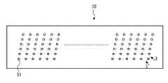
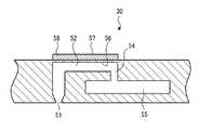
図2は記録ヘッド30の吐出面を示した平面図であり、図3は記録ヘッド30の一部断面図(図2中3−3線に沿う断面図)である。図2において、ヘッド30の長手方向(ヘッド長手方向)は図1の紙面表裏方向に相当する。本実施形態の記録ヘッド30は、中間転写体12上に形成される画像の最大記録幅に対応する長さに渡って多数の吐出口(ノズル)51が形成されたフルラインヘッドで構成されている。図示するように、各ノズル51はヘッド長手方向及びヘッド長手方向に直交しない斜めの方向に沿って2次元状(マトリクス状)に配列されており、このような高密度なノズル配置によって、中間転写体12上に高解像な画像記録を実現することができる。 FIG. 2 is a plan view showing the ejection surface of the
この記録ヘッド30には、図3に示すように、ノズル51に連通する圧力室52がノズル51毎に設けられている。圧力室52の一端には供給口54が形成されており、圧力室52は供給口54を介して共通流路55に連通している。共通流路55には所定の液体(処理液又は各色インク)が貯留されており、共通流路55から圧力室52に対して液体が供給される。 As shown in FIG. 3, the
圧力室52の一壁面(図3の上面)は振動板56で構成されており、振動板56上の圧力室52に対応する位置には圧電素子58が設けられている。圧電素子58の上面には、個別電極57が設けられている。尚、本実施形態では振動板56が導電材料で構成され、圧電素子58に対する共通電極を兼ねている。 One wall surface (the upper surface in FIG. 3) of the
かかる構成により、圧電素子58に駆動電圧が印加されると、圧電素子58の変位に応じて圧力室52内の液体が加圧され、ノズル51から液滴が吐出される。吐出後、共通流路55から圧力室52に液体が供給される。 With this configuration, when a driving voltage is applied to the
尚、本実施形態では、圧電素子58を利用して吐出を行う圧電方式の態様を例示したが、本発明の実施に際してはこれに限定されず、例えば、ヒータに代表される電気熱変換素子を利用して吐出を行うサーマル方式やその他各種方式であってもよい。 In the present embodiment, the piezoelectric mode in which ejection is performed using the
図4はインクジェット記録装置10のシステム構成を示す要部ブロック図である。インクジェット記録装置10は、通信インターフェース70、システムコントローラ72、画像メモリ74、モータドライバ76、ヒータドライバ78、プリント制御部80、画像バッファメモリ82、処理液用ヘッドドライバ83、インク用ヘッドドライバ84等を備えている。 FIG. 4 is a principal block diagram showing the system configuration of the
通信インターフェース70は、ホストコンピュータ86から送られてくる画像データを受信するインターフェース部である。通信インターフェース70にはシリアルインターフェースやパラレルインターフェースを適用することができる。この部分には、通信を高速化するためのバッファメモリ(不図示)を搭載してもよい。 The
ホストコンピュータ86から送出された画像データは通信インターフェース70を介してインクジェット記録装置10に取り込まれ、一旦画像メモリ74に記憶される。画像メモリ74は、通信インターフェース70を介して入力された画像を一旦格納する記憶手段であり、システムコントローラ72を通じてデータの読み書きが行われる。画像メモリ74は、半導体素子からなるメモリに限らず、ハードディスクなど磁気媒体を用いてもよい。 Image data sent from the
システムコントローラ72は、通信インターフェース70、画像メモリ74、モータドライバ76、ヒータドライバ78等の各部を制御する制御部である。システムコントローラ72は、中央演算処理装置(CPU)及びその周辺回路等から構成され、ホストコンピュータ86との間の通信制御、画像メモリ74の読み書き制御等を行うとともに、各部のモータ88やヒータ89を制御する制御信号を生成する。 The
モータドライバ76は、システムコントローラ72からの指示に従ってモータ88を駆動するドライバ(駆動回路)である。ヒータドライバ78は、システムコントローラ72からの指示に従ってヒータ89を駆動するドライバである。 The
プリント制御部80は、システムコントローラ72の制御に従い、画像メモリ74内の画像データから印字制御用の信号を生成するための各種加工、補正などの処理を行う信号処理機能を有し、生成した印字制御信号(ドットデータ)を各ヘッドドライバ83、84に供給する制御部である。プリント制御部80において所要の信号処理が施され、該画像データに基づいて各ヘッドドライバ83、84を介してそれぞれ対応する記録ヘッド30(30S、30K、30M、30C、30Y)の液滴の吐出量や吐出タイミングの制御が行われる。これにより、所望のドットサイズやドット配置が実現される。尚、本発明の特徴である吐出制御はプリント制御部80の吐出制御部80aで行われる。 The
プリント制御部80には画像バッファメモリ82が備えられており、プリント制御部80における画像データ処理時に画像データやパラメータなどのデータが画像バッファメモリ82に一時的に格納される。なお、図4において画像バッファメモリ82はプリント制御部80に付随する態様で示されているが、画像メモリ74と兼用することも可能である。また、プリント制御部80とシステムコントローラ72とを統合して1つのプロセッサで構成する態様も可能である。 The
各ヘッドドライバ83、84(処理液用ヘッドドライバ83、インク用ヘッドドライバ84)は、プリント制御部80から与えられるドットデータに基づいてそれぞれ対応する記録ヘッド30(30S、30K、30C、30M、30Y)の各圧電素子58(図3参照)を駆動するための駆動信号を生成し、圧電素子58に生成した駆動信号を供給する。各ヘッドドライバ83、84には記録ヘッド30の駆動条件を一定に保つためのフィードバック制御系を含んでいてもよい。 The
次に、本発明の特徴部分である吐出制御について詳説する。 Next, the discharge control which is a characteristic part of the present invention will be described in detail.
本実施形態のインクジェット記録装置10は、前述したように、2種類の液体(処理液及びインク)を用いて、中間転写体12上に画像を形成し、中間転写体12上に形成された画像を記録媒体34に転写することで記録媒体34上に画像を形成する中間転写型の記録装置であり、80ppm以上の高速記録が可能な高速システムである。本実施形態では、このような高速システムにおける転写不良を防ぐために、以下に示す2つの条件(第1及び第2の吐出制御条件)のいずれか一方の条件を満たすような吐出制御を行っている。 As described above, the ink
まず、第1の吐出制御条件について説明する。第1の吐出制御条件は、中間転写体12上にインク滴が着弾する際の(中間転写体12上の)処理液(層)の最小厚みが1μm以上であり、且つ、単位面積当りの処理液付与量が単位面積当りのインク付与量以上であるという条件である。尚、「処理液の最小厚み」とは、中間転写体12上に形成された処理液層のうち最も厚さが小さくなる部分の厚みをいう。また「処理液の最大厚み」とは、中間転写体12上に形成された処理液層のうち最も厚さが大きくなる部分の厚みをいう。 First, the first discharge control condition will be described. The first discharge control condition is that the minimum thickness of the processing liquid (layer) when ink droplets land on the
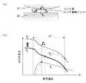
図5は良好な転写の必要条件を説明するための図である。同図の(a)は転写部18の一部拡大図であり、中間転写体12上に着弾したインク滴(インク着弾ドット)が記録媒体34に転写される様子を示している。中間転写体12とインク着弾ドットの間の付着力をf1、インク着弾ドットの凝集力をf2、記録媒体34とインク着弾ドットの間の付着力をf3とするとき、中間転写体12から記録媒体34に対してインク着弾ドットを良好に転写するためには、次式f2>f3>f1を満足することが必要条件となる。同図の(b)は各力f1,f2,f3の関係を一例として示したグラフであり、良好な転写領域(転写温度範囲)はPで示した範囲となる。このような関係において、インク着弾ドットの凝集力をf2からf2′(>f2)に向上させることができれば、良好な転写領域(転写温度範囲)をP′(>P)に広げることができ、転写率を向上させることができる。FIG. 5 is a diagram for explaining the necessary conditions for good transfer. FIG. 6A is a partially enlarged view of the
以上から、転写率を向上させるためには、中間転写体12上に着弾するインク滴(インク着弾ドット)の凝集力を向上させることが必要であり、そのためには、本実施形態の如く、中間転写体12に対してインクに先立って処理液を付与することが必要となる。処理液の付与方法としては、次に説明するように、中間転写体12上に付与された処理液中にインク滴が浸る状態にすることが好ましい。 From the above, in order to improve the transfer rate, it is necessary to improve the cohesive force of ink droplets (ink landing dots) that land on the
図6は処理液及びインクの付与量と転写率との関係を示した図である。 FIG. 6 is a diagram showing the relationship between the application amount of the treatment liquid and ink and the transfer rate.
同図の(a)に示すように、単位面積当りの処理液の付与量が単位面積当りのインクの付与量未満の場合、中間転写体12上に着弾したインク滴は、中間転写体12に先に形成された処理液中に完全に浸らず、処理液と反応しない未反応領域(十分に反応しない領域含む)が生じてしまう。このような未反応領域が存在する状態で転写が行われると、図示するように、中間転写体12上のインク滴(インク着弾ドット)は引きちぎられてしまい(このような現象を「ドット割れ」という。)、中間転写体12上の画像が記録媒体34に正確に転写されず、転写後の中間転写体12に残存物が残ってしまう。 As shown in FIG. 5A, when the amount of treatment liquid applied per unit area is less than the amount of ink applied per unit area, ink droplets that land on the
一方、同図の(b)に示すように、単位面積当りの処理液の付与量が単位面積当りのインクの付与量以上の場合、中間転写体12上に着弾したインク滴は処理液中に浸るので、インク滴の全領域で処理液との反応が進み、中間転写体12から記録媒体34への転写時にインク滴自体が弾性的特性を示すのでドット割れが生じることなく、中間転写体12上の画像が記録媒体34に正常に転写される。 On the other hand, as shown in FIG. 5B, when the applied amount of the processing liquid per unit area is equal to or larger than the applied amount of ink per unit area, the ink droplets landed on the
画質の観点ではインク滴の拡がり率は1.5以上4.0以下が好ましい。尚、拡がり率とは、飛翔中のインク滴の直径D1に対する着弾後安定状態にあるインク滴(インク着弾ドット)の直径D2の比(D2/D1)である。From the viewpoint of image quality, the spreading rate of ink droplets is preferably 1.5 or more and 4.0 or less. The spreading rate is a ratio (D2 / D1 ) of the diameter D2 of the ink droplet (ink landing dot) in a stable state after landing to the diameter D1 of the ink droplet in flight.
図7は、インク滴の拡がり率とその高さの関係を示したグラフである。同図において、例えば、インク滴の体積が2plの場合には、所望の拡がり率(1.5以上4.0以下)を満足するインク滴の高さ(厚み)は実測で0.9〜4.6μmとなる。このため、中間転写体12上に付与される処理液(層)の最小厚みを1μm以上にする必要がある。インク滴の体積が他の場合(3pl、7pl)についても同様であり、インク滴の体積にかかわらず、処理液の最小厚みは1μm以上にすることが好ましい。 FIG. 7 is a graph showing the relationship between the spreading rate of ink droplets and their height. In the figure, for example, when the volume of the ink droplet is 2 pl, the height (thickness) of the ink droplet satisfying a desired spreading ratio (1.5 or more and 4.0 or less) is 0.9 to 4 in actual measurement. .6 μm. For this reason, the minimum thickness of the processing liquid (layer) applied on the
一方、処理液の最大厚みが大きいほど、凝集色材が中間転写体12に馴染まずに処理液中で浮遊し、中間転写体12上での画像乱れが発生しやすくなることから、中間転写体12上の処理液の最大厚みは9μm以下であることが好ましい。 On the other hand, as the maximum thickness of the processing liquid increases, the aggregated color material floats in the processing liquid without becoming familiar with the
以上から、転写不良を防止するためには、中間転写体12上にインク滴が着弾する際の処理液の最小厚みが1μm以上であり、且つ、単位面積当りの処理液付与量が単位面積当りのインク付与量以上であるという条件を満足するように吐出制御を行うことが好ましい。これにより、中間転写体12上の処理液中にインク滴が浸る状態となり、インク滴全体で反応が促進され、インクに含有される溶媒不溶性材料(色材等)を直ちに凝集させることができる。従って、中間転写体12上の画像品質が向上すると共に、高速システムを組んだ場合でも、中間転写体12から記録媒体34への転写を良好に行うことができる。このため、転写後の中間転写体12上に残存物を残すことなく、転写後の中間転写体12に対するクリーニング負荷を低減することができる。 From the above, in order to prevent transfer failure, the minimum thickness of the processing liquid when ink droplets land on the
複数の色インクが用いられる場合、単位面積当りの処理液の付与量が、各色インクのうち単位面積当りの付与量が最大となる色インクの付与量以上となるようにすればよい。本実施形態の場合では4種類の色インク(KCMY)が用いられるが、画像領域中の単位面積当りの処理液の付与量をVS(g/m2)、ブラック、シアン、マゼンダ、イエローの各色インクの単位面積当りの付与量をVK(g/m2)、VC(g/m2)、VM(g/m2)、VY(g/m2)とすると、次式が満たされるように処理液を付与すればよい。When a plurality of color inks are used, the amount of treatment liquid applied per unit area may be equal to or greater than the amount of color ink applied per unit area of each color ink. In the case of this embodiment, four types of color inks (KCMY) are used. The application amount of the processing liquid per unit area in the image area is VS (g / m2 ), black, cyan, magenta, and yellow.Assuming that the application amount of each color ink per unit area is VK (g / m2 ), VC (g / m2 ), VM (g / m2 ), and VY (g / m2 ), The treatment liquid may be applied so that
VS≧VK, VC, VM, VY
次に、第2の吐出制御条件について説明する。第2の吐出制御条件は、中間転写体12上にインク滴が着弾する際の処理液の最小厚みが1μm以上であり、且つ、インク滴が着弾する画像領域だけでなく、その画像領域を囲む周辺領域にも処理液を付与するという条件である。V S ≧ V K, V C , V M, V Y
Next, the second discharge control condition will be described. The second ejection control condition is that the minimum thickness of the treatment liquid when the ink droplets land on the
一般的に、転写率を向上させるため中間転写体12は撥液性の高い材質で構成されることが多く、中間転写体12上に着弾した処理液は球形に近い形状となり、その乾燥速度は速く、2plの液滴の乾燥時間(温度25℃、湿度50%)は約0.14sとなる。本実施形態では、中間転写体12上に処理液が付与されてからインク滴が付与されるまでのタイムラグは0.1s程度である。即ち、処理液の乾燥時間と処理液付与からインク付与までのタイムラグが略一致することから、中間転写体12上での処理液の乾燥を考慮する必要がある。尚、記録媒体に処理液やインクを直接付与する方式の場合には処理液は記録媒体に直ちに浸透するため処理液の乾燥は問題となりにくい。 In general, in order to improve the transfer rate, the
このようなことから、中間転写体12上に付与された処理液が乾燥して引けの現象が発生しても、インク滴との反応に十分な量の処理液が中間転写体12上に残った状態でインク滴が着弾するように、中間転写体12上にインク滴が着弾する際の処理液の最小厚みが1μm以上であり、且つ、インク滴が着弾する画像領域だけでなく、その画像領域を囲む周辺領域にも処理液を付与することが好ましい。尚、インク滴が着弾する際の処理液の最小厚みを1μm以上とする理由は、前述した第1の吐出制御条件と同様であるので説明は省略する。 For this reason, even if the processing liquid applied on the
図8は第2の吐出制御条件における処理液の付与例を示した図である。同図において、内側に示した1又は複数の塗り潰しドットは処理液及びインク滴の着弾位置を表しており、こられ塗り潰しドットを囲む非塗り潰し(白抜き)ドットは処理液の着弾位置を表している。インク滴が着弾する画像領域のx方向の長さをlx、y方向の長さをly、インク滴の着弾によって形成されるドット(インク着弾ドット)のドット径をDとしたとき、図示するように、lx×lyの画像領域を内部に含む(lx+2D)×(ly+2D)の領域に対して処理液が付与される。FIG. 8 is a diagram showing an example of applying the treatment liquid under the second discharge control condition. In the figure, one or more filled dots shown on the inside represent the landing positions of the treatment liquid and ink droplets, and the non-filled (white dots) surrounding the filled dots represent the landing positions of the treatment liquid. Yes. Assuming that the length in the x direction of the image area where the ink droplets land is lx , the length in the y direction is ly , and the dot diameter of the dots (ink landing dots) formed by the landing of the ink droplets is D as to the processing liquid is applied to a region of including an image region ofl x ×l y inside(l x + 2D) × ( l y + 2D).
このように第2の吐出制御条件では、インク滴が着弾する画像領域に対して処理液を付与するだけでなく、その画像領域を囲む周辺領域、好ましくは画像領域から外側四方にそれぞれ少なくともインク着弾ドットのドットに相当する大きさだけ広げた領域にも処理液を付与する。 As described above, in the second ejection control condition, not only the treatment liquid is applied to the image area on which the ink droplets land, but also at least the ink landing on the peripheral area surrounding the image area, preferably on the outer four sides from the image area. The treatment liquid is also applied to an area widened by a size corresponding to a dot.
これにより、中間転写体12上で処理液が乾燥して引けの現象が発生しても、インク滴との反応に十分な量の処理液が残る。従って、中間転写体12上の画像品質が向上すると共に、高速システムを組んだ場合でも、中間転写体12から記録媒体34への転写を良好に行うことができる。このため、転写後の中間転写体12上に残存物を残すことなく、転写後の中間転写体12に対するクリーニング負荷を低減することができる。 As a result, even when the processing liquid dries on the
前述した各吐出制御条件において、処理液の表面張力はインクの表面張力以下であることが好ましい。これにより、処理液はインクの凝集反応を促す機能だけでなく、インクの濡れ性を向上させる機能を有することになるので、インクの濡れ性が向上し、中間転写体12上に着弾するインク滴の拡がり率を1.5以上4.0以下にすることができ、中間転写体12上の画像品質を向上させることができる。 In each discharge control condition described above, the surface tension of the treatment liquid is preferably equal to or less than the surface tension of the ink. As a result, the treatment liquid has not only a function of promoting the agglomeration reaction of the ink but also a function of improving the wettability of the ink, so that the wettability of the ink is improved and the ink droplets that land on the
また、インク中に含まれる溶媒不溶性材料の含有濃度としては、画質や吐出安定性の観点から、1重量%〜20重量%の範囲であることが好ましい。不溶性材料の含有濃度がこの範囲より小さい場合には画質として充分な光学濃度を得られず、一方、この範囲より大きい場合にはインク粘度の上昇によって吐出安定性が低下するためである。 Further, the concentration of the solvent-insoluble material contained in the ink is preferably in the range of 1% by weight to 20% by weight from the viewpoint of image quality and ejection stability. If the concentration of the insoluble material is less than this range, a sufficient optical density for image quality cannot be obtained. On the other hand, if the concentration is greater than this range, the ejection stability decreases due to an increase in ink viscosity.
また、各吐出制御条件において、処理液が中間転写体12上で略均一厚みとなるように付与されることが好ましい。更に、好ましくは、中間転写体12上で処理液の拡がり率を2以上とする。また、中間転写体12に対する処理液の接触角を70度以下とする。また、中間転写体12の材質を剥離性の高い低表面エネルギー材料(例えば、シリコーンゴム、フッ素ゴム等)で構成する。また、処理液が界面活性剤を含むようにする。 In each discharge control condition, it is preferable that the treatment liquid is applied on the
また、各吐出制御条件において、図9の(a)、(b)に示すように、中間転写体12上に着弾したインク滴(インク着弾ドット)の表面に処理液が即座に濡れ拡がることが好ましい。これにより、同一色又は異なる色間のインク滴同士の着弾干渉を防止することができる。これを実現するためには、例えば、処理液に低分子の界面活性剤を入れればよい。より好ましくは、中間転写体12上にインク滴が着弾してから処理液が塗れ拡がるまでの時間は30μs以下、また、塗れ拡がる速度は0.5m/s以上とする。 Further, under each discharge control condition, as shown in FIGS. 9A and 9B, the treatment liquid may immediately spread on the surface of the ink droplets (ink landing dots) that have landed on the
本実施形態では、処理液用ヘッド30Sから処理液を吐出することによって中間転写体12上に処理液を付与する態様としたが、本発明の実施に際しては、処理液の付与方法は特に限定されるものではない。 In the present embodiment, the processing liquid is applied onto the
本実施形態の変形例として、処理液用ヘッド30Sに代えて、塗布ローラーを用いて中間転写体12上に処理液を塗布する態様もある。中間転写体12上のインク滴が着弾する画像領域を含むほぼ全面に処理液を容易に付与することができる。本変形例において、好ましくは、中間転写体12上の処理液の厚みを1〜5μmとする。中間転写体12上の処理液の厚みを一定にする手段を設けてもよい。例えば、エアナイフを用いる方法や、尖鋭な角を有する部材を処理液厚みの規定量のギャップを中間転写体12との間に設けて設置する方法がある。 As a modification of the present embodiment, there is an aspect in which the treatment liquid is applied onto the
尚、本実施形態では、第1の液体として色材を含有するインクを用いた態様を示したが、本発明の実施に際してはこれに限定されない。例えば、金属を含有する液体を第1の液体として用いて、記録媒体上に配線パターンを転写形成する態様もある。 In the present embodiment, an embodiment in which an ink containing a color material is used as the first liquid is shown. However, the present invention is not limited to this. For example, there is an embodiment in which a wiring pattern is transferred and formed on a recording medium using a liquid containing a metal as the first liquid.
次に、実施例を挙げて本発明を更に具体的に説明する。 Next, the present invention will be described more specifically with reference to examples.
[インク]
インクとして、下記の組成のものを使用した。
・ 顔料 5重量%
・ グリセリン 20重量%
・ ジエチレングリコール 10重量%
・ オリフィン 1重量%
・ ラテックス 5重量%
・ 純水 59重量%
顔料としては,C.I.ピグメントイエロー12,13,17,55,74,97,120,128,151,155,及び180,またはC.I.ピグメントレッド122,C.I.ピグメントバイオレット19,C.I.ピグメントレッド57:1,146,およびC.I.ピグメントブルー15:3,のいずれでも良いがサンプルとしてピグメントレッドを使用した。[ink]
The ink having the following composition was used.
・ 5% by weight of pigment
・
・
・
・
・ 59% pure water
Examples of pigments include
ラテックスとして、記録メディア(記録媒体)への定着性向上、耐擦過性向上、転写率向上を目的として、スチレン-イソプレン系ラテックスを使用した。 As the latex, styrene-isoprene latex was used for the purpose of improving fixability to a recording medium (recording medium), improving scratch resistance, and improving transfer rate.
定着性向上、耐擦過性向上、及び転写率向上材料としては、アクリル系、ウレタン系、ポリエステル系、ビニル系、スチレン系などが考えられる。定着性向上、耐擦過性向上、及び転写率向上材料といった機能を充分に発現させるには、比較的高分子のポリマーを高濃度(1重量%〜20重量%)に添加することが必要である。しかし、上記材料をインクに溶解させて添加しようとすると高粘度化し、吐出性が低下する。適切な材料を高濃度に添加し、且つ、粘度上昇を抑えるには、ラテックスとして添加する手段が有効である。ラテックス材料としては、アクリル酸アルキル共重合体、カルボキシ変性SBR(スチレン−ブタジエンラテックス)、SIR(スチレン−イソプレン)ラテックス、MBR(メタクリル酸メチル−ブタジエンラテックス)、NBR(アクリロニトリル−ブタジエンラテックス)などが考えられる。 As materials for improving the fixing property, improving the scratch resistance, and improving the transfer rate, acrylic, urethane, polyester, vinyl, styrene, and the like can be considered. It is necessary to add a relatively high molecular weight polymer (1 wt% to 20 wt%) in order to fully exhibit functions such as fixing property improvement, scratch resistance improvement and transfer rate improving material. . However, if an attempt is made to dissolve and add the above material to the ink, the viscosity becomes high and the discharge property is lowered. In order to add an appropriate material at a high concentration and suppress an increase in viscosity, a means of adding as a latex is effective. Latex materials include alkyl acrylate copolymers, carboxy-modified SBR (styrene-butadiene latex), SIR (styrene-isoprene) latex, MBR (methyl methacrylate-butadiene latex), NBR (acrylonitrile-butadiene latex), and the like. It is done.
ラテックスのガラス転移点Tgはプロセス上、転写時に影響の強い値で、常温安定性と加熱後の転写性を考慮すると50℃以上120℃以下であることが好ましい。更に、最低造膜温度MFTはプロセス上、定着時に影響の強い値で100℃以下、更に好ましく50℃以下である。 The glass transition point Tg of the latex is a value that has a strong influence upon transfer in the process, and is preferably 50 ° C. or higher and 120 ° C. or lower in consideration of normal temperature stability and transferability after heating. Further, the minimum film-forming temperature MFT is a value having a strong influence upon fixing in the process, and is 100 ° C. or less, more preferably 50 ° C. or less.
分散性良好なラテックス材質を複数種類用意してインクを作製し、アート紙上にベタ画像を得て、アート紙とのテープ剥離テスト、擦り試験、転写率測定を実施した。その結果を表1に示す。 A plurality of types of latex materials with good dispersibility were prepared, ink was prepared, solid images were obtained on art paper, and a tape peeling test, rubbing test, and transfer rate measurement with art paper were performed. The results are shown in Table 1.

表1に示すとおり、定着性、耐擦過性、転写率の全ての項目においてアクリル性ラテックスを使用したものが良好であった。SBRについてはアート紙表面層にSBR材料を含有しているため、定着性、耐擦過性、転写率ともに良好な結果を得られたと考えられる。 As shown in Table 1, those using acrylic latex were good in all items of fixability, scratch resistance and transfer rate. With respect to SBR, since the surface layer of art paper contains an SBR material, it is considered that good results were obtained in terms of fixability, scratch resistance, and transfer rate.
本実施例では、ラテックスをインクに添加しているが、処理液に添加しても、また、別ヘッドにてラテックス分散物のみを転写前に添加しても同程度の定着性が得られることは確認済みである。 In this example, latex is added to the ink. However, even if it is added to the treatment liquid or only the latex dispersion is added before transfer by another head, the same level of fixability can be obtained. Has been confirmed.
25℃環境下でインク表面張力10mN/mから50mN/m、粘度は1mPa・sから20mPa・sの範囲となるように設定した。本実施例では、インク表面張力が31.2mN/m、粘度4.9mPa・sとした。 The ink surface tension was set in the range of 10 mN / m to 50 mN / m and the viscosity in the range of 1 mPa · s to 20 mPa · s in a 25 ° C. environment. In this embodiment, the ink surface tension was 31.2 mN / m and the viscosity was 4.9 mPa · s.
[処理液]
処理液として、下記の組成のものを用いた。
・ フッ素系界面活性剤 0.1重量%
・ 純水 99.9重量%
処理液は、低pHの液体であり、インクと混合するとインク中の色材を凝集させる機能を有している。中間転写体12として用いられるシリコーンゴムに対する処理液の接触角は62度であり比較的濡れ易いものであった。[Treatment solution]
A treatment liquid having the following composition was used.
・ Fluorosurfactant 0.1% by weight
・ Pure water 99.9% by weight
The treatment liquid is a low-pH liquid and has a function of aggregating the color material in the ink when mixed with the ink. The contact angle of the treatment liquid with respect to the silicone rubber used as the
25℃環境下で処理液の表面張力10mN/mから50mN/m、粘度は1mPa・sから20mPa・sに設定した。本実施例では、処理液の表面張力が28.0mN/m、粘度3.1mPa・sとした。 Under a 25 ° C. environment, the surface tension of the treatment liquid was set to 10 mN / m to 50 mN / m, and the viscosity was set to 1 mPa · s to 20 mPa · s. In this example, the surface tension of the treatment liquid was 28.0 mN / m, and the viscosity was 3.1 mPa · s.
[画像形成装置]
画像形成装置として、図1に示したインクジェット記録装置10のうち、中間転写体12、処理液供給部14、マーキング部16、及び転写部18から成る基本構成に溶媒除去部20を加えた装置構成のものを使用した。具体的な装置構成や条件は以下に示すとおりである。
・ 中間転写体12として、シリコーンゴムシートSRシリーズ0.5mm厚(タイガースポリマー社製)を使用した。
・ 処理液供給部14及びマーキング部16にはそれぞれ1個の記録ヘッドが備えられた最小構成とし、記録ヘッドとして、圧電方式(ピエゾ方式)でPX−G920(エプソン社製)を使用した。尚、処理液供給部14の記録ヘッド(処理液用ヘッド)は、マーキング部16の記録ヘッド(インク用ヘッド)よりも低解像度のものを使用することも可能であるが、本実施例では同性能のものを使用した。
・ 溶媒除去ローラー26として、金属多孔質体(酸化チタン粒子を焼結した材質)を使用した。
・ 転写部18における転写圧を10kPaとし、転写部18における各ローラー36、26Bの加熱温度を80℃とした。
・ 中間転写体12の搬送速度(回転速度)及び記録媒体34の搬送速度はいずれも0.5m/s(120ppm相当)に設定した。
・ 記録媒体34としては、アート紙(特菱アート、三菱製紙製)を用いた。[Image forming apparatus]
In the ink
As the
The treatment
As the
The transfer pressure at the
The conveyance speed (rotational speed) of the
-As the
[評価1]
このような処理液、インク及び画像形成装置を用いて、処理液の1滴当りの液滴量を14pl、インクの1滴当りの液滴量を7plと設定し、インク滴の拡がり率が3.5〜4.0となるようにして、次の転写実験を行った。尚、本発明の実施に際しては、各記録ヘッド30から吐出される1滴当りの液滴量は特に限定されるものでなく、処理液>インク、処理液=インク、処理液<インク、のいずれでもよい。[Evaluation 1]
Using such processing liquid, ink, and image forming apparatus, the droplet volume per droplet of processing liquid is set to 14 pl, the droplet volume per droplet of ink is set to 7 pl, and the ink droplet spreading rate is 3 The following transfer experiment was performed so that the ratio was 0.5 to 4.0. In the practice of the present invention, the amount of droplets ejected from each
本転写実験では、中間転写体12上に付与される処理液の最小厚みと、単位面積当りのインク付与量に対する単位面積当りの処理液付与量の比をそれぞれ適当な範囲で変化させながら、中間転写体12上に略真円のインク着弾ドットを形成し、中間転写体12上の任意の25個(=5×5)のインク着弾ドットのうち、何個が欠けなく完全に転写できたかを計測した。このとき、完全に転写された割合を転写率とし、転写率90%未満の場合を×、転写率90%以上95%未満の場合を○、転写率95%以上の場合を◎として判定を行った。その結果を表2に示す。 In this transfer experiment, the minimum thickness of the processing liquid applied onto the
表2から分かるように、処理液の最小厚みが1μm以上であり、且つ、単位面積当りのインク付与量に対する単位面積当りの処理液付与量の比が1以上であるというような条件を満たす場合には90%以上の転写率を得られることが分かった。一方、前記条件を満たさない場合には転写率が90%未満となり、転写不良が発生しやすいことが確認された。 As can be seen from Table 2, the condition that the minimum thickness of the treatment liquid is 1 μm or more and the ratio of the treatment liquid application amount per unit area to the ink application amount per unit area is 1 or more is satisfied. It was found that a transfer rate of 90% or more can be obtained. On the other hand, when the above conditions were not satisfied, the transfer rate was less than 90%, and it was confirmed that transfer defects were likely to occur.
[評価2]
また、処理液の1滴当りの液滴量を7pl、インクの1滴当りの液滴量を7plに設定し、処理液の最小厚みが3μmとなるようにして、次の転写実験を行った。[Evaluation 2]
In addition, the following transfer experiment was performed by setting the droplet volume per one drop of the processing liquid to 7 pl, the droplet volume per one drop of the ink to 7 pl, and the minimum thickness of the processing liquid to 3 μm. .
本転写実験では、処理液の付与領域を変化させながら、図7の(a)に示すような1つのインク着弾ドットから成る画像を25個作成し、転写できた画像数を計測した。このとき、正常に転写された画像の割合を転写成功率とし、転写成功率90%未満の場合を×、転写成功率90%以上95%未満の場合を○、転写成功率95%以上の場合を◎として判定を行った。その結果を表3に示す。 In this transfer experiment, 25 images composed of one ink landing dot as shown in FIG. 7A were created while changing the treatment liquid application region, and the number of transferred images was measured. At this time, the rate of successful transfer is the transfer success rate, x is the transfer success rate less than 90%, ○ is the transfer success rate is 90% or more and less than 95%, and the transfer success rate is 95% or more. Judgment was made as ◎. The results are shown in Table 3.
表3から分かるように、画像領域から外側四方にそれぞれ少なくとも1ドットずつ広げた領域に対して処理液を付与する場合には90%以上の転写成功率を得られることが分かった。また、(lx+3D)×(ly+3D)以上の広い領域に対してはいずれも転写成功率100%と良好な結果を得られることを確認した。ただし、処理液量低減の観点から、処理液の付与領域を(lx+3D)×(ly+3D)以下の領域とすることが望ましい。As can be seen from Table 3, it was found that a transfer success rate of 90% or more can be obtained when the treatment liquid is applied to an area where at least one dot is spread outward from the image area. In addition, it was confirmed that good results were obtained with a transfer success rate of 100% for a wide region of (lx + 3D) × (ly + 3D) or more. However, from the viewpoint of reducing the amount of the processing liquid, it is desirable that the application area of the processing liquid be an area of (lx + 3D) × (ly + 3D) or less.
一方、画像領域から外側四方に1ドット未満広げた領域に処理液を付与する場合には転写成功率が90%未満となり、転写不良が発生しやすいことが確認された。 On the other hand, in the case where the treatment liquid is applied to an area extended from the image area by less than 1 dot on the outer four sides, the transfer success rate is less than 90%, and it has been confirmed that transfer defects are likely to occur.
[評価3]
処理液の1滴当りの液滴量を7pl、インクの1滴当りの液適量を7plに設定し、次の転写実験を行った。[Evaluation 3]
The following transfer experiment was conducted with the droplet volume per droplet of the treatment liquid set to 7 pl and the appropriate liquid volume per droplet of ink set to 7 pl.
本転写実験では、処理液の最大厚みを変化させた場合のインク滴の拡がり率を計測した。その際、中間転写体12の材質として、シリコーンゴム(処理液との接触角:27°)とPET(処理液との接触角:7°)のそれぞれを利用した場合について計測を行った。その結果を図10に示す。 In this transfer experiment, the spreading rate of ink droplets when the maximum thickness of the treatment liquid was changed was measured. At that time, measurement was carried out for the case where silicone rubber (contact angle with the treatment liquid: 27 °) and PET (contact angle with the treatment liquid: 7 °) were used as the material of the
前述したように画像品質の観点からインク滴の拡がり率は1.5から4.0が望ましく、中間転写体12の材質がシリコーンゴム(処理液との接触角:27°)、PET(処理液との接触角:7°)のいずれの場合においても、処理液の最大厚みを9μm以下とすることで所望のインク滴の拡がり率を達成することが確認された。 As described above, the spreading rate of ink droplets is preferably 1.5 to 4.0 from the viewpoint of image quality, and the material of the
一方、処理液の最大厚みが9μmより大きい場合には、インク滴の拡がり率が急激に低下することが確認された。その原因としては、インク滴が処理液から受ける抗力による影響と考えられる。即ち、処理液の最大厚みが大きいとインク滴が中間転写体12に衝突することなく、または低速度で中間転写体12に衝突し、中間転写体12上でインク滴が充分拡がらないまま、処理液中で凝集体を形成してしまうため、インク滴の拡がり率が低下するものと推察される。 On the other hand, it was confirmed that when the maximum thickness of the treatment liquid is larger than 9 μm, the spreading rate of the ink droplets is rapidly decreased. The cause is considered to be the influence of the drag that the ink droplet receives from the treatment liquid. That is, when the maximum thickness of the treatment liquid is large, the ink droplet does not collide with the
以上、本発明の画像形成装置及び画像形成方法について詳細に説明したが、本発明は、以上の例には限定されず、本発明の要旨を逸脱しない範囲において、各種の改良や変形を行ってもよいのはもちろんである。 The image forming apparatus and the image forming method of the present invention have been described in detail above. However, the present invention is not limited to the above examples, and various improvements and modifications are made without departing from the gist of the present invention. Of course it is also good.
10…インクジェット記録装置、12…中間転写体、14…処理液供給部、16…マーキング部、18…転写部、20…溶媒除去部、22…クリーニング部、24…画像定着部、26…溶媒除去ローラー、30…記録ヘッド、30S…記録ヘッド(処理液用ヘッド)、30K、30C、30M、30Y…記録ヘッド(インク用ヘッド)、34…記録媒体、36…加圧ローラー、38…クリーニングローラー、40A、40B…定着ローラー、51…ノズル、52…圧力室、54…供給口、55…共通流路、56…振動板、58…圧電素子、80…プリント制御部、80a…吐出制御部、83…処理液用ヘッドドライバ、84…インク用ヘッドドライバ DESCRIPTION OF
Claims (9)
Translated fromJapanese溶媒不溶性材料を含有する第1の液体を前記中間転写体上に付与する第1の液体付与手段と、
前記溶媒不溶性材料を凝集させる機能を有する第2の液体を前記第1の液体に先立って前記中間転写体上に付与する第2の液体付与手段と、
前記第1の液体を付与する際の前記中間転写体上の前記第2の液体の最小厚みが1μm以上であり、且つ、単位面積当りの前記第2の液体の付与量が単位面積あたりの前記第1の液体の付与量以上であるように制御する吐出制御手段と、を備えたことを特徴とする画像形成装置。An image forming apparatus that forms an image on the recording medium by transferring the image formed on the intermediate transfer member to the recording medium,
First liquid applying means for applying a first liquid containing a solvent-insoluble material onto the intermediate transfer member;
A second liquid applying means for applying a second liquid having a function of aggregating the solvent-insoluble material onto the intermediate transfer body prior to the first liquid;
When the first liquid is applied, the minimum thickness of the second liquid on the intermediate transfer member is 1 μm or more, and the application amount of the second liquid per unit area is the per unit area. An image forming apparatus comprising: an ejection control unit that performs control so as to be equal to or greater than an application amount of the first liquid.
溶媒不溶性材料を含有する第1の液体を前記中間転写体上に付与する第1の液体付与手段と、
前記溶媒不溶性材料を凝集させる機能を有する第2の液体を前記第1の液体に先立って前記中間転写体上に付与する第2の液体付与手段と、
前記第1の液体を付与する際の前記中間転写体上の前記第2の液体の最小厚みが1μm以上であり、且つ、前記第1の液体の付与領域だけでなく前記第1の液体の付与領域を囲む周辺領域にも前記第2の液体を付与する吐出制御手段と、を備えたことを特徴とする画像形成装置。An image forming apparatus that forms an image on the recording medium by transferring the image formed on the intermediate transfer member to the recording medium,
First liquid applying means for applying a first liquid containing a solvent-insoluble material onto the intermediate transfer member;
A second liquid applying means for applying a second liquid having a function of aggregating the solvent-insoluble material onto the intermediate transfer body prior to the first liquid;
When the first liquid is applied, the minimum thickness of the second liquid on the intermediate transfer member is 1 μm or more, and not only the first liquid application region but also the application of the first liquid is performed. An image forming apparatus comprising: an ejection control unit that applies the second liquid to a peripheral region surrounding the region.
溶媒不溶性材料を含有する第1の液体に先立って、前記溶媒不溶性材料を凝集させる機能を有する第2の液体を前記中間転写体上に付与する工程と、
前記中間転写体上に前記第1の液体を付与する工程と、を含み、
前記第1の液体を付与する際の前記中間転写体上の前記第2の液体の最小厚みが1μm以上であり、且つ、単位面積当りの前記第2の液体の付与量が単位面積あたりの前記第1の液体の付与量以上であることを特徴とする画像形成方法。An image forming method for forming an image on a recording medium by transferring the image formed on the intermediate transfer member to the recording medium,
Providing a second liquid having a function of aggregating the solvent-insoluble material on the intermediate transfer body prior to the first liquid containing the solvent-insoluble material;
Applying the first liquid onto the intermediate transfer member,
When the first liquid is applied, the minimum thickness of the second liquid on the intermediate transfer member is 1 μm or more, and the application amount of the second liquid per unit area is the per unit area. An image forming method, wherein the image forming amount is equal to or greater than the application amount of the first liquid.
溶媒不溶性材料を含有する第1の液体に先立って、前記溶媒不溶性材料を凝集させる機能を有する第2の液体を前記中間転写体上に付与する工程と、
前記中間転写体上に前記第1の液体を付与する工程と、を含み、
前記第1の液体を付与する際の前記中間転写体上の前記第2の液体の最小厚みが1μm以上であり、且つ、前記第1の液体の付与領域だけでなく前記第1の液体の付与領域を囲む周辺領域にも前記第2の液体を付与することを特徴とする画像形成方法。
An image forming method for forming an image on a recording medium by transferring the image formed on the intermediate transfer member to the recording medium,
Providing a second liquid having a function of aggregating the solvent-insoluble material on the intermediate transfer body prior to the first liquid containing the solvent-insoluble material;
Applying the first liquid onto the intermediate transfer member,
When the first liquid is applied, the minimum thickness of the second liquid on the intermediate transfer member is 1 μm or more, and not only the first liquid application region but also the application of the first liquid is performed. An image forming method comprising applying the second liquid to a peripheral region surrounding the region.
Priority Applications (2)
| Application Number | Priority Date | Filing Date | Title |
|---|---|---|---|
| JP2006095813AJP2007268802A (en) | 2006-03-30 | 2006-03-30 | Image forming apparatus and image forming method |
| US11/730,129US7780286B2 (en) | 2006-03-30 | 2007-03-29 | Image forming apparatus and image forming method |
Applications Claiming Priority (1)
| Application Number | Priority Date | Filing Date | Title |
|---|---|---|---|
| JP2006095813AJP2007268802A (en) | 2006-03-30 | 2006-03-30 | Image forming apparatus and image forming method |
Publications (1)
| Publication Number | Publication Date |
|---|---|
| JP2007268802Atrue JP2007268802A (en) | 2007-10-18 |
Family
ID=38558280
Family Applications (1)
| Application Number | Title | Priority Date | Filing Date |
|---|---|---|---|
| JP2006095813APendingJP2007268802A (en) | 2006-03-30 | 2006-03-30 | Image forming apparatus and image forming method |
Country Status (2)
| Country | Link |
|---|---|
| US (1) | US7780286B2 (en) |
| JP (1) | JP2007268802A (en) |
Cited By (7)
| Publication number | Priority date | Publication date | Assignee | Title |
|---|---|---|---|---|
| EP2813365A1 (en) | 2013-06-12 | 2014-12-17 | Canon Kabushiki Kaisha | Intermediate transfer member and image recording method |
| EP2933109A1 (en) | 2014-04-17 | 2015-10-21 | Canon Kabushiki Kaisha | Intermediate transfer member, image-recording method, and image-recording apparatus |
| JP2019010812A (en)* | 2017-06-30 | 2019-01-24 | キヤノン株式会社 | Inkjet recording method and inkjet recording apparatus |
| JP2019127015A (en)* | 2018-01-26 | 2019-08-01 | コニカミノルタ株式会社 | Image forming apparatus and cleaning method |
| JP2019130714A (en)* | 2018-01-30 | 2019-08-08 | コニカミノルタ株式会社 | Image forming method and image forming apparatus |
| JP2021507826A (en)* | 2017-12-07 | 2021-02-25 | ランダ コーポレイション リミテッド | Digital printing process and method |
| JP2022154957A (en)* | 2021-03-30 | 2022-10-13 | ブラザー工業株式会社 | liquid ejection head |
Families Citing this family (61)
| Publication number | Priority date | Publication date | Assignee | Title |
|---|---|---|---|---|
| WO2007142358A1 (en)* | 2006-06-09 | 2007-12-13 | Canon Kabushiki Kaisha | Image fixing method, method for producing record product using such method, and image recording apparatus |
| ATE550197T1 (en)* | 2008-04-18 | 2012-04-15 | Hewlett Packard Development Co | PRINTING APPARATUS AND CONTROL METHOD |
| EP2459382B1 (en)* | 2009-07-31 | 2014-11-12 | Hewlett-Packard Development Company, L.P. | Inkjet ink and intermediate transfer medium for inkjet printing |
| JP5743398B2 (en)* | 2009-12-16 | 2015-07-01 | キヤノン株式会社 | Image forming method and image forming apparatus |
| US10632740B2 (en) | 2010-04-23 | 2020-04-28 | Landa Corporation Ltd. | Digital printing process |
| GB2513816B (en) | 2012-03-05 | 2018-11-14 | Landa Corporation Ltd | Digital printing system |
| US9902147B2 (en) | 2012-03-05 | 2018-02-27 | Landa Corporation Ltd. | Digital printing system |
| WO2013132420A1 (en) | 2012-03-05 | 2013-09-12 | Landa Corporation Limited | Printing system |
| HK1204640A1 (en) | 2012-03-05 | 2015-11-27 | Landa Corporation Ltd. | Ink film constructions |
| US10190012B2 (en) | 2012-03-05 | 2019-01-29 | Landa Corporation Ltd. | Treatment of release layer and inkjet ink formulations |
| CN104220539B (en) | 2012-03-05 | 2016-06-01 | 兰达公司 | Ink film structure |
| US10434761B2 (en) | 2012-03-05 | 2019-10-08 | Landa Corporation Ltd. | Digital printing process |
| US9643403B2 (en) | 2012-03-05 | 2017-05-09 | Landa Corporation Ltd. | Printing system |
| JP6220354B2 (en) | 2012-03-05 | 2017-10-25 | ランダ コーポレイション リミテッド | Control apparatus and method for digital printing system |
| US10642198B2 (en) | 2012-03-05 | 2020-05-05 | Landa Corporation Ltd. | Intermediate transfer members for use with indirect printing systems and protonatable intermediate transfer members for use with indirect printing systems |
| US9498946B2 (en) | 2012-03-05 | 2016-11-22 | Landa Corporation Ltd. | Apparatus and method for control or monitoring of a printing system |
| JP6437312B2 (en) | 2012-03-05 | 2018-12-12 | ランダ コーポレイション リミテッド | Digital printing process |
| EP2825486B1 (en) | 2012-03-15 | 2019-01-02 | Landa Corporation Ltd. | Endless flexible belt for a printing system |
| US9174432B2 (en)* | 2012-12-17 | 2015-11-03 | Xerox Corporation | Wetting enhancement coating on intermediate transfer member (ITM) for aqueous inkjet intermediate transfer architecture |
| US9242455B2 (en) | 2013-07-16 | 2016-01-26 | Xerox Corporation | System and method for transfixing an aqueous ink in an image transfer system |
| GB2518149B (en)* | 2013-09-11 | 2018-04-18 | Landa Corporation Ltd | Apparatus for treating an intermediate transfer member of a printing system |
| GB201401173D0 (en) | 2013-09-11 | 2014-03-12 | Landa Corp Ltd | Ink formulations and film constructions thereof |
| US9683130B2 (en) | 2014-03-19 | 2017-06-20 | Xerox Corporation | Polydiphenylsiloxane coating formulation and method for forming a coating |
| US9227393B2 (en) | 2014-03-19 | 2016-01-05 | Xerox Corporation | Wetting enhancement coating on intermediate transfer member (ITM) for aqueous inkjet intermediate transfer architecture |
| US9494884B2 (en) | 2014-03-28 | 2016-11-15 | Xerox Corporation | Imaging plate coating composite composed of fluoroelastomer and aminosilane crosslinkers |
| US9138985B1 (en)* | 2014-05-14 | 2015-09-22 | Xerox Corporation | Indirect printing apparatus employing printhead for depositing a sacrificial coating composition on an intermediate transfer member and method for depositing the sacrifical coating |
| US9428663B2 (en) | 2014-05-28 | 2016-08-30 | Xerox Corporation | Indirect printing apparatus employing sacrificial coating on intermediate transfer member |
| US9593255B2 (en) | 2014-09-23 | 2017-03-14 | Xerox Corporation | Sacrificial coating for intermediate transfer member of an indirect printing apparatus |
| US9550908B2 (en) | 2014-09-23 | 2017-01-24 | Xerox Corporation | Sacrificial coating for intermediate transfer member of an indirect printing apparatus |
| US9611404B2 (en) | 2014-09-23 | 2017-04-04 | Xerox Corporation | Method of making sacrificial coating for an intermediate transfer member of indirect printing apparatus |
| US9421758B2 (en) | 2014-09-30 | 2016-08-23 | Xerox Corporation | Compositions and use of compositions in printing processes |
| JP6391422B2 (en) | 2014-10-23 | 2018-09-19 | キヤノン株式会社 | Recording method and recording apparatus |
| EP3012105B1 (en)* | 2014-10-23 | 2019-08-14 | Canon Kabushiki Kaisha | Recording method and recording apparatus |
| US9956760B2 (en) | 2014-12-19 | 2018-05-01 | Xerox Corporation | Multilayer imaging blanket coating |
| US9458341B2 (en) | 2015-02-12 | 2016-10-04 | Xerox Corporation | Sacrificial coating compositions comprising polyvinyl alcohol and waxy starch |
| GB2536489B (en) | 2015-03-20 | 2018-08-29 | Landa Corporation Ltd | Indirect printing system |
| US9816000B2 (en) | 2015-03-23 | 2017-11-14 | Xerox Corporation | Sacrificial coating and indirect printing apparatus employing sacrificial coating on intermediate transfer member |
| GB2537813A (en) | 2015-04-14 | 2016-11-02 | Landa Corp Ltd | Apparatus for threading an intermediate transfer member of a printing system |
| US9718964B2 (en) | 2015-08-19 | 2017-08-01 | Xerox Corporation | Sacrificial coating and indirect printing apparatus employing sacrificial coating on intermediate transfer member |
| GB201602877D0 (en) | 2016-02-18 | 2016-04-06 | Landa Corp Ltd | System and method for generating videos |
| US10933661B2 (en) | 2016-05-30 | 2021-03-02 | Landa Corporation Ltd. | Digital printing process |
| GB201609463D0 (en) | 2016-05-30 | 2016-07-13 | Landa Labs 2012 Ltd | Method of manufacturing a multi-layer article |
| US10926532B2 (en) | 2017-10-19 | 2021-02-23 | Landa Corporation Ltd. | Endless flexible belt for a printing system |
| US11267239B2 (en) | 2017-11-19 | 2022-03-08 | Landa Corporation Ltd. | Digital printing system |
| US11511536B2 (en) | 2017-11-27 | 2022-11-29 | Landa Corporation Ltd. | Calibration of runout error in a digital printing system |
| US11707943B2 (en) | 2017-12-06 | 2023-07-25 | Landa Corporation Ltd. | Method and apparatus for digital printing |
| JP2019104147A (en)* | 2017-12-11 | 2019-06-27 | キヤノン株式会社 | Inkjet recording method and inkjet recording device |
| CN117885446A (en) | 2018-06-26 | 2024-04-16 | 兰达公司 | Intermediate transmission components of digital printing systems |
| US10994528B1 (en) | 2018-08-02 | 2021-05-04 | Landa Corporation Ltd. | Digital printing system with flexible intermediate transfer member |
| US12001902B2 (en) | 2018-08-13 | 2024-06-04 | Landa Corporation Ltd. | Correcting distortions in digital printing by implanting dummy pixels in a digital image |
| WO2020075012A1 (en) | 2018-10-08 | 2020-04-16 | Landa Corporation Ltd. | Friction reduction means for printing systems and method |
| CN116080260A (en) | 2018-12-24 | 2023-05-09 | 兰达公司 | Digital printing system and method |
| US12358277B2 (en) | 2019-03-31 | 2025-07-15 | Landa Corporation Ltd. | Systems and methods for preventing or minimizing printing defects in printing processes |
| JP7685995B2 (en) | 2019-11-25 | 2025-05-30 | ランダ コーポレイション リミテッド | Drying of ink in digital printing using infrared radiation absorbed by particles embedded within an ITM |
| US11321028B2 (en) | 2019-12-11 | 2022-05-03 | Landa Corporation Ltd. | Correcting registration errors in digital printing |
| JP7657229B2 (en) | 2019-12-29 | 2025-04-04 | ランダ コーポレイション リミテッド | Printing method and system |
| US11478991B2 (en) | 2020-06-17 | 2022-10-25 | Xerox Corporation | System and method for determining a temperature of an object |
| US11499873B2 (en) | 2020-06-17 | 2022-11-15 | Xerox Corporation | System and method for determining a temperature differential between portions of an object printed by a 3D printer |
| US11498354B2 (en) | 2020-08-26 | 2022-11-15 | Xerox Corporation | Multi-layer imaging blanket |
| US11767447B2 (en) | 2021-01-19 | 2023-09-26 | Xerox Corporation | Topcoat composition of imaging blanket with improved properties |
| EP4264377A4 (en) | 2021-02-02 | 2024-11-13 | Landa Corporation Ltd. | REDUCING DISTORTIONS IN PRINTED IMAGES |
Citations (4)
| Publication number | Priority date | Publication date | Assignee | Title |
|---|---|---|---|---|
| JPH05229112A (en)* | 1991-09-30 | 1993-09-07 | Toshiba Corp | Recording method and recording apparatus |
| JP2003171589A (en)* | 2001-12-07 | 2003-06-20 | Konica Corp | Pigment ink for ink-jet, and ink-jet cartridge, ink-jet image recording method and ink-jet recorded image using the same |
| JP2005343049A (en)* | 2004-06-03 | 2005-12-15 | Canon Inc | Inkjet recording method and inkjet recording apparatus |
| JP2006056078A (en)* | 2004-08-18 | 2006-03-02 | Canon Inc | Image forming method and image forming apparatus |
Family Cites Families (8)
| Publication number | Priority date | Publication date | Assignee | Title |
|---|---|---|---|---|
| JP2002370441A (en) | 2001-06-15 | 2002-12-24 | Canon Inc | Intermediate transfer type inkjet recording method |
| US6682189B2 (en)* | 2001-10-09 | 2004-01-27 | Nexpress Solutions Llc | Ink jet imaging via coagulation on an intermediate member |
| WO2004022353A1 (en) | 2002-09-04 | 2004-03-18 | Canon Kabushiki Kaisha | Image forming process and image forming apparatus |
| JP4006374B2 (en) | 2002-09-04 | 2007-11-14 | キヤノン株式会社 | Image forming method, image forming apparatus, and recorded product manufacturing method |
| US7997717B2 (en)* | 2003-06-23 | 2011-08-16 | Canon Kabushiki Kaisha | Image forming method, image forming apparatus, intermediate transfer body, and method of modifying surface of intermediate transfer body |
| JP4054721B2 (en) | 2003-06-23 | 2008-03-05 | キヤノン株式会社 | Image forming method and image forming apparatus |
| JP4054722B2 (en) | 2003-06-23 | 2008-03-05 | キヤノン株式会社 | Image forming method, image forming apparatus, and recorded product manufacturing method |
| JP4834300B2 (en)* | 2003-11-20 | 2011-12-14 | キヤノン株式会社 | Inkjet recording method and inkjet recording apparatus |
- 2006
- 2006-03-30JPJP2006095813Apatent/JP2007268802A/enactivePending
- 2007
- 2007-03-29USUS11/730,129patent/US7780286B2/ennot_activeExpired - Fee Related
Patent Citations (4)
| Publication number | Priority date | Publication date | Assignee | Title |
|---|---|---|---|---|
| JPH05229112A (en)* | 1991-09-30 | 1993-09-07 | Toshiba Corp | Recording method and recording apparatus |
| JP2003171589A (en)* | 2001-12-07 | 2003-06-20 | Konica Corp | Pigment ink for ink-jet, and ink-jet cartridge, ink-jet image recording method and ink-jet recorded image using the same |
| JP2005343049A (en)* | 2004-06-03 | 2005-12-15 | Canon Inc | Inkjet recording method and inkjet recording apparatus |
| JP2006056078A (en)* | 2004-08-18 | 2006-03-02 | Canon Inc | Image forming method and image forming apparatus |
Cited By (11)
| Publication number | Priority date | Publication date | Assignee | Title |
|---|---|---|---|---|
| EP2813365A1 (en) | 2013-06-12 | 2014-12-17 | Canon Kabushiki Kaisha | Intermediate transfer member and image recording method |
| US9354557B2 (en) | 2013-06-12 | 2016-05-31 | Canon Kabushiki Kaisha | Intermediate transfer member and image recording method |
| EP2933109A1 (en) | 2014-04-17 | 2015-10-21 | Canon Kabushiki Kaisha | Intermediate transfer member, image-recording method, and image-recording apparatus |
| US9316956B2 (en) | 2014-04-17 | 2016-04-19 | Canon Kabushiki Kaisha | Intermediate transfer member, image-recording method, and image-recording apparatus |
| JP2019010812A (en)* | 2017-06-30 | 2019-01-24 | キヤノン株式会社 | Inkjet recording method and inkjet recording apparatus |
| JP2021507826A (en)* | 2017-12-07 | 2021-02-25 | ランダ コーポレイション リミテッド | Digital printing process and method |
| JP7273038B2 (en) | 2017-12-07 | 2023-05-12 | ランダ コーポレイション リミテッド | Digital printing process and method |
| JP2019127015A (en)* | 2018-01-26 | 2019-08-01 | コニカミノルタ株式会社 | Image forming apparatus and cleaning method |
| JP2019130714A (en)* | 2018-01-30 | 2019-08-08 | コニカミノルタ株式会社 | Image forming method and image forming apparatus |
| JP7087411B2 (en) | 2018-01-30 | 2022-06-21 | コニカミノルタ株式会社 | Image forming method and image forming device |
| JP2022154957A (en)* | 2021-03-30 | 2022-10-13 | ブラザー工業株式会社 | liquid ejection head |
Also Published As
| Publication number | Publication date |
|---|---|
| US20070229639A1 (en) | 2007-10-04 |
| US7780286B2 (en) | 2010-08-24 |
Similar Documents
| Publication | Publication Date | Title |
|---|---|---|
| JP2007268802A (en) | Image forming apparatus and image forming method | |
| JP5051887B2 (en) | Liquid coating apparatus and method, and image forming apparatus | |
| US7712890B2 (en) | Image forming apparatus and image forming method | |
| US8322843B2 (en) | Inkjet recording apparatus and inkjet recording method | |
| JP5085893B2 (en) | Image forming apparatus and ink set | |
| JP4054721B2 (en) | Image forming method and image forming apparatus | |
| JP4006386B2 (en) | Image forming method and image forming apparatus | |
| JP2008006816A (en) | Image forming apparatus and image forming method | |
| JP4054722B2 (en) | Image forming method, image forming apparatus, and recorded product manufacturing method | |
| JP5006934B2 (en) | Image forming method and image forming apparatus | |
| JP5020015B2 (en) | Liquid coating apparatus and inkjet recording apparatus | |
| JP2009234219A (en) | Image forming method and image forming apparatus | |
| JP2009083314A (en) | Image forming method and ink jet recording apparatus | |
| JP4903024B2 (en) | Image forming apparatus and image forming method | |
| JP2009083317A (en) | Image forming method and image forming apparatus | |
| JP2009240925A (en) | Apparatus and method for applying liquid, inkjet recording apparatus and method therefor | |
| JP2010260204A (en) | Inkjet recording device | |
| JP2008074018A (en) | Image forming apparatus | |
| US8235519B2 (en) | Image forming apparatus and method | |
| JP2008238485A (en) | Inkjet recording method and inkjet recording apparatus | |
| JP4950099B2 (en) | Image forming method and image forming apparatus | |
| JP2009082830A (en) | WAX agent application device, WAX agent application method, and image forming apparatus | |
| JP5196524B2 (en) | Image forming method and image forming apparatus | |
| JP2010214880A (en) | Image forming apparatus and mist catching method | |
| JP4977505B2 (en) | Inkjet recording method and inkjet recording apparatus |
Legal Events
| Date | Code | Title | Description |
|---|---|---|---|
| A621 | Written request for application examination | Free format text:JAPANESE INTERMEDIATE CODE: A621 Effective date:20080708 | |
| A977 | Report on retrieval | Free format text:JAPANESE INTERMEDIATE CODE: A971007 Effective date:20101206 | |
| A131 | Notification of reasons for refusal | Free format text:JAPANESE INTERMEDIATE CODE: A131 Effective date:20101209 | |
| A521 | Written amendment | Free format text:JAPANESE INTERMEDIATE CODE: A523 Effective date:20110204 | |
| A02 | Decision of refusal | Free format text:JAPANESE INTERMEDIATE CODE: A02 Effective date:20110222 |