JP2007266504A - Exposure equipment - Google Patents
Exposure equipmentDownload PDFInfo
- Publication number
- JP2007266504A JP2007266504AJP2006092338AJP2006092338AJP2007266504AJP 2007266504 AJP2007266504 AJP 2007266504AJP 2006092338 AJP2006092338 AJP 2006092338AJP 2006092338 AJP2006092338 AJP 2006092338AJP 2007266504 AJP2007266504 AJP 2007266504A
- Authority
- JP
- Japan
- Prior art keywords
- substrate
- liquid
- exposure apparatus
- coplanar
- wafer
- Prior art date
- Legal status (The legal status is an assumption and is not a legal conclusion. Google has not performed a legal analysis and makes no representation as to the accuracy of the status listed.)
- Withdrawn
Links
Images


Classifications
- G—PHYSICS
- G03—PHOTOGRAPHY; CINEMATOGRAPHY; ANALOGOUS TECHNIQUES USING WAVES OTHER THAN OPTICAL WAVES; ELECTROGRAPHY; HOLOGRAPHY
- G03B—APPARATUS OR ARRANGEMENTS FOR TAKING PHOTOGRAPHS OR FOR PROJECTING OR VIEWING THEM; APPARATUS OR ARRANGEMENTS EMPLOYING ANALOGOUS TECHNIQUES USING WAVES OTHER THAN OPTICAL WAVES; ACCESSORIES THEREFOR
- G03B27/00—Photographic printing apparatus
- G03B27/32—Projection printing apparatus, e.g. enlarger, copying camera
- G03B27/42—Projection printing apparatus, e.g. enlarger, copying camera for automatic sequential copying of the same original
- G—PHYSICS
- G03—PHOTOGRAPHY; CINEMATOGRAPHY; ANALOGOUS TECHNIQUES USING WAVES OTHER THAN OPTICAL WAVES; ELECTROGRAPHY; HOLOGRAPHY
- G03F—PHOTOMECHANICAL PRODUCTION OF TEXTURED OR PATTERNED SURFACES, e.g. FOR PRINTING, FOR PROCESSING OF SEMICONDUCTOR DEVICES; MATERIALS THEREFOR; ORIGINALS THEREFOR; APPARATUS SPECIALLY ADAPTED THEREFOR
- G03F7/00—Photomechanical, e.g. photolithographic, production of textured or patterned surfaces, e.g. printing surfaces; Materials therefor, e.g. comprising photoresists; Apparatus specially adapted therefor
- G03F7/70—Microphotolithographic exposure; Apparatus therefor
- G03F7/70216—Mask projection systems
- G03F7/70341—Details of immersion lithography aspects, e.g. exposure media or control of immersion liquid supply
- G—PHYSICS
- G03—PHOTOGRAPHY; CINEMATOGRAPHY; ANALOGOUS TECHNIQUES USING WAVES OTHER THAN OPTICAL WAVES; ELECTROGRAPHY; HOLOGRAPHY
- G03D—APPARATUS FOR PROCESSING EXPOSED PHOTOGRAPHIC MATERIALS; ACCESSORIES THEREFOR
- G03D3/00—Liquid processing apparatus involving immersion; Washing apparatus involving immersion
- G—PHYSICS
- G03—PHOTOGRAPHY; CINEMATOGRAPHY; ANALOGOUS TECHNIQUES USING WAVES OTHER THAN OPTICAL WAVES; ELECTROGRAPHY; HOLOGRAPHY
- G03F—PHOTOMECHANICAL PRODUCTION OF TEXTURED OR PATTERNED SURFACES, e.g. FOR PRINTING, FOR PROCESSING OF SEMICONDUCTOR DEVICES; MATERIALS THEREFOR; ORIGINALS THEREFOR; APPARATUS SPECIALLY ADAPTED THEREFOR
- G03F7/00—Photomechanical, e.g. photolithographic, production of textured or patterned surfaces, e.g. printing surfaces; Materials therefor, e.g. comprising photoresists; Apparatus specially adapted therefor
- G03F7/70—Microphotolithographic exposure; Apparatus therefor
- G03F7/70691—Handling of masks or workpieces
- G03F7/70716—Stages
- G—PHYSICS
- G03—PHOTOGRAPHY; CINEMATOGRAPHY; ANALOGOUS TECHNIQUES USING WAVES OTHER THAN OPTICAL WAVES; ELECTROGRAPHY; HOLOGRAPHY
- G03F—PHOTOMECHANICAL PRODUCTION OF TEXTURED OR PATTERNED SURFACES, e.g. FOR PRINTING, FOR PROCESSING OF SEMICONDUCTOR DEVICES; MATERIALS THEREFOR; ORIGINALS THEREFOR; APPARATUS SPECIALLY ADAPTED THEREFOR
- G03F7/00—Photomechanical, e.g. photolithographic, production of textured or patterned surfaces, e.g. printing surfaces; Materials therefor, e.g. comprising photoresists; Apparatus specially adapted therefor
- G03F7/70—Microphotolithographic exposure; Apparatus therefor
- G03F7/708—Construction of apparatus, e.g. environment aspects, hygiene aspects or materials
- G03F7/70858—Environment aspects, e.g. pressure of beam-path gas, temperature
- H—ELECTRICITY
- H01—ELECTRIC ELEMENTS
- H01L—SEMICONDUCTOR DEVICES NOT COVERED BY CLASS H10
- H01L21/00—Processes or apparatus adapted for the manufacture or treatment of semiconductor or solid state devices or of parts thereof
- H01L21/67—Apparatus specially adapted for handling semiconductor or electric solid state devices during manufacture or treatment thereof; Apparatus specially adapted for handling wafers during manufacture or treatment of semiconductor or electric solid state devices or components ; Apparatus not specifically provided for elsewhere
- H01L21/67005—Apparatus not specifically provided for elsewhere
- H01L21/67242—Apparatus for monitoring, sorting or marking
- H01L21/67248—Temperature monitoring
Landscapes
- Physics & Mathematics (AREA)
- General Physics & Mathematics (AREA)
- Engineering & Computer Science (AREA)
- Health & Medical Sciences (AREA)
- Life Sciences & Earth Sciences (AREA)
- Environmental & Geological Engineering (AREA)
- Epidemiology (AREA)
- Public Health (AREA)
- Atmospheric Sciences (AREA)
- Toxicology (AREA)
- Condensed Matter Physics & Semiconductors (AREA)
- Manufacturing & Machinery (AREA)
- Computer Hardware Design (AREA)
- Microelectronics & Electronic Packaging (AREA)
- Power Engineering (AREA)
- Exposure Of Semiconductors, Excluding Electron Or Ion Beam Exposure (AREA)
- Exposure And Positioning Against Photoresist Photosensitive Materials (AREA)
Abstract
Translated fromJapaneseDescription
Translated fromJapanese本発明は、デバイス(半導体デバイスや液晶表示デバイス等)を製造するためのリソグラフィー工程において使用される露光装置に関するものである。 The present invention relates to an exposure apparatus used in a lithography process for manufacturing a device (such as a semiconductor device or a liquid crystal display device).
原版としてのレチクルに描画された回路パターン像を、投影光学系によって感光基板としてのウエハやガラスプレート等に投影し、その感光基板を露光する装置として、従来から投影露光装置が使用されている。 Conventionally, a projection exposure apparatus has been used as an apparatus for projecting a circuit pattern image drawn on a reticle as an original onto a wafer or glass plate as a photosensitive substrate by a projection optical system and exposing the photosensitive substrate.
近年では、投影光学系と感光基板との間に液体を介在させて、投影光学系の最終面と感光基板との間の媒質の屈折率を大きくすることにより高解像度を実現する液浸露光装置が注目されている。この液浸露光装置は、投影光学系と感光基板(以下、単に「基板」ともいう。)の間を液体で満たすことで、投影光学系の開口数(NA)を増加させるものである。投影光学系の開口数(NA)は、液体(媒質)の屈折率をnとすると、NA=n・sinθで求めることができるので、空気の屈折率よりも高い屈折率(n>1)の媒質を満たすことでNAをnまで大きくすることができる。この関係より、プロセス定数k1と光源の波長λによって表される液浸露光装置の解像度R(R=k1(λ/NA))を小さくすることができる。 In recent years, an immersion exposure apparatus that realizes high resolution by interposing a liquid between the projection optical system and the photosensitive substrate and increasing the refractive index of the medium between the final surface of the projection optical system and the photosensitive substrate. Is attracting attention. This immersion exposure apparatus increases the numerical aperture (NA) of the projection optical system by filling the space between the projection optical system and the photosensitive substrate (hereinafter also simply referred to as “substrate”) with a liquid. The numerical aperture (NA) of the projection optical system can be obtained by NA = n · sin θ, where n is the refractive index of the liquid (medium), so that the refractive index (n> 1) is higher than the refractive index of air. The NA can be increased to n by filling the medium. From this relationship, the resolution R (R = k1 (λ / NA)) of the immersion exposure apparatus expressed by the process constant k1 and the wavelength λ of the light source can be reduced.
例えば、投影光学系の最終面と、ウエハの表面との間に局所的に液体を充填する所謂ローカルフィル方式の液浸露光装置が提案されている。ローカルフィル方式の液浸露光装置においては、ウエハ外周部を露光する際に投影光学系の最終面とウエハの表面との間に局所的に液体を保持するために、特別な機構が必要となる。例えば、特許文献1〜4には、ウエハ外周部に隣接し、ウエハの表面とほぼ同じ高さの同面部材(補助部材)をステージ天板上に有する液浸露光装置が提案されている。 For example, a so-called local fill type immersion exposure apparatus has been proposed in which a liquid is locally filled between the final surface of the projection optical system and the surface of the wafer. In the local fill immersion exposure apparatus, a special mechanism is required to locally hold the liquid between the final surface of the projection optical system and the surface of the wafer when exposing the outer periphery of the wafer. . For example, Patent Documents 1 to 4 propose an immersion exposure apparatus that has a coplanar member (auxiliary member) on a stage top plate that is adjacent to the outer peripheral portion of the wafer and has substantially the same height as the surface of the wafer.
特許文献3では、回収孔や多孔質部材をウエハステージ上に配置し、真空ポンプ等で負圧にしたラインに接続することで、基板外周部の溝に入り込んだ液浸水を吸引回収する構成を開示している。
ステージ天板上にウエハとほぼ同じ高さの同面部材を設ける場合、ウエハをスキャンする際に投影光学系の最終面とウエハの表面との間に局所的に保持された液膜(LW)の一部が同面部材の表面上に薄く残ることとなる。同面部材の表面上に薄く残った液膜が気化すると同面部材の温度を低下させることになり、温度の低下により同面部材が熱変形(収縮)して同面部材を支持する天板が変形してしまうという問題が生じる。天板が変形することにより、天板近傍に設けられているレーザー干渉計の計測ミラーとウエハとの相対的な位置関係が変化してしまうことになり、ウエハの位置や姿勢の計測精度が悪化するという問題が生じる。 When a coplanar member having substantially the same height as the wafer is provided on the stage top plate, a liquid film (LW) locally held between the final surface of the projection optical system and the surface of the wafer when scanning the wafer A part of the thin film remains on the surface of the same surface member. When the liquid film that remains thin on the surface of the coplanar member is vaporized, the temperature of the coplanar member is lowered, and the coplanar member is thermally deformed (contracted) by the decrease in temperature to support the coplanar member. This causes a problem of deformation. Due to the deformation of the top plate, the relative positional relationship between the measurement mirror of the laser interferometer provided near the top plate and the wafer changes, and the measurement accuracy of the position and orientation of the wafer deteriorates. Problem arises.
更に、残った液浸液を回収するために、ウエハステージに回収孔部材もしくは多孔質部材を設けて負圧による吸引を行う場合、吸引により液浸液周辺の気圧が下がることで、少なからず液浸液の気化が促進されることになる。つまり、液浸液周辺の圧力と液浸液の蒸気圧との相対関係で気化される量が変化し、周辺の圧力が下がる方向に推移する場合は通常気化量が増加する。それに伴い気化熱の影響で吸引部分である回収孔部材もしくは多孔質部材、更には真空ポンプまでの流路周辺が冷えやすくなってしまう。液浸液として代表的に使用される(純)水では、特に単位質量あたりの気化熱量(潜熱)が非常に大きく1gの水が気化する際に約2400Jもの熱を奪うことが知られている。液浸水から発生する気化熱は部材表面から直接的かつ大きな熱量を奪い、また局所的であるため、分布も含めて高精度に同面部材全体の温調を行うのは難しい。そのため、現実的には温調を行っても、ある程度はウエハ同面部材の温度変化により熱変形が生じてしまい、露光精度が悪化してしまうという問題が生じる。 Furthermore, in order to recover the remaining immersion liquid, when a suction hole member or a porous member is provided on the wafer stage and suction is performed with a negative pressure, the pressure around the immersion liquid is reduced by the suction. The vaporization of the immersion liquid will be promoted. That is, the amount of vaporization changes depending on the relative relationship between the pressure around the immersion liquid and the vapor pressure of the immersion liquid, and the amount of vaporization usually increases when the pressure around the immersion liquid changes. Along with this, the recovery hole member or the porous member, which is the suction portion, and the periphery of the flow path to the vacuum pump are easily cooled due to the influence of heat of vaporization. It is known that (pure) water typically used as an immersion liquid has a very large amount of heat of vaporization (latent heat) per unit mass and takes about 2400 J of heat when 1 g of water is vaporized. . Since the heat of vaporization generated from the immersion water directly takes a large amount of heat from the member surface and is local, it is difficult to control the temperature of the entire coplanar member with high accuracy including distribution. Therefore, in practice, even if the temperature is adjusted, there is a problem that thermal deformation occurs due to a temperature change of the wafer coplanar member, and the exposure accuracy deteriorates.
本発明は、上記問題点を鑑みてなれたものであり、液浸液による気化熱の影響で同面部材に発生する熱変形の影響を受けない、露光精度に優れた露光技術の提供を目的するものである。 The present invention has been made in view of the above problems, and an object thereof is to provide an exposure technique with excellent exposure accuracy that is not affected by thermal deformation generated in the same surface member due to the heat of vaporization caused by the immersion liquid. To do.
本発明の一側面としての露光装置は、投影光学系と基板との間を液体で満たした状態で原版のパターンを前記基板に露光する露光装置であって、基板ステージ上に保持されている前記基板と、前記基板の外周部の周辺領域とを略同一面にして前記基板の外周部に液体を保持する同面部材(補助部材)、を備え、前記同面部材は、前記基板の外周部の周辺領域に構成され、前記基板の外周部に液体を保持する内側部材と、前記内側部材の外周部に構成され、前記基板ステージに取り付けられる外側部材と、前記内側部材と前記外側部材とを結合する結合部材と、を有することを特徴とする。 An exposure apparatus according to one aspect of the present invention is an exposure apparatus that exposes a pattern of an original on the substrate in a state where a space between a projection optical system and the substrate is filled with a liquid, and is held on a substrate stage. A coplanar member (auxiliary member) that holds a liquid in the outer peripheral portion of the substrate with the substrate and a peripheral region of the outer peripheral portion of the substrate being substantially flush with each other, and the coplanar member is an outer peripheral portion of the substrate An inner member that holds liquid on the outer peripheral portion of the substrate, an outer member that is configured on the outer peripheral portion of the inner member and is attached to the substrate stage, and the inner member and the outer member. And a coupling member to be coupled.
本発明の別の一側面としての露光装置は、投影光学系と基板との間を液体で満たした状態で原版のパターンを前記基板に露光する露光装置であって、基板ステージ上に保持されている前記基板と、前記基板の外周部の周辺領域とを略同一面にして前記基板の外周部に液体を保持する同面部材(補助部材)と、前記同面部材を前記基板ステージ上に取り付けるための取付部材と、を備え、前記取付部材は、前記同面部材に生じた変形を弾性変形により吸収し、前記基板ステージに伝達される変形を低減させることを特徴とする。 An exposure apparatus according to another aspect of the present invention is an exposure apparatus that exposes a pattern of an original on the substrate in a state where a space between a projection optical system and the substrate is filled with a liquid, and is held on a substrate stage. The substrate and the peripheral area of the outer peripheral portion of the substrate are substantially flush with each other, and a coplanar member (auxiliary member) that holds liquid on the outer peripheral portion of the substrate, and the coplanar member is mounted on the substrate stage And a mounting member for absorbing deformation caused by the coplanar member by elastic deformation, and reducing deformation transmitted to the substrate stage.
本発明によれば、液体による気化熱の影響で同面部材に発生する熱変形の影響を受けない、露光精度に優れた露光装置の提供が可能となる。 According to the present invention, it is possible to provide an exposure apparatus with excellent exposure accuracy that is not affected by the thermal deformation generated in the same surface member due to the heat of vaporization caused by the liquid.
以下、本発明の実施形態を添付の図面に基づいて詳細に説明する。尚、各図において、同一の部材については同一の参照番号を付し、重複する説明は省略するものとする。 Embodiments of the present invention will be described below in detail with reference to the accompanying drawings. In addition, in each figure, the same reference number is attached | subjected about the same member and the overlapping description shall be abbreviate | omitted.
(第1実施形態)
(液浸露光装置の構成)
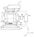
図1は本発明の第1実施形態に係る液浸型の露光装置1(以下、単に「露光装置」ともいう)の構成を示す図である。(First embodiment)
(Configuration of immersion exposure equipment)
FIG. 1 is a view showing the configuration of an immersion type exposure apparatus 1 (hereinafter also simply referred to as “exposure apparatus”) according to the first embodiment of the present invention.
露光装置1は、投影光学系30のウエハ40側にある最終面と、ウエハ40との間に供給される液体(液浸液)LWを介して、レチクル20に形成された回路パターンをステップ・アンド・スキャン方式でウエハ40に露光することが可能である。ここで、「ステップ・アンド・スキャン方式」とは、レチクル20に対してウエハ40を連続的に走査してレチクルパターンをウエハの露光領域に露光すると共に、1ショットの露光終了後にウエハを次の露光領域にステップ移動させて露光する方法である。 The exposure apparatus 1 steps the circuit pattern formed on the
尚、本発明の趣旨は、露光方法をステップ・アンド・スキャン方式に限定するものではなく、露光領域を一括して露光した後に、次の露光領域を露光する「ステップ・アンド・リピート方式」の液浸型の投影露光装置に適用することも可能である。 Note that the gist of the present invention is not to limit the exposure method to the step-and-scan method, but the “step-and-repeat method” in which the exposure region is exposed in a lump and then the next exposure region is exposed. It is also possible to apply to an immersion type projection exposure apparatus.
露光装置1は、照明装置10、レチクル20を載置するレチクルステージ25、投影光学系30、ウエハ40を載置するウエハステージ45を有する。また、露光装置1は、測距装置(52、56、54、58)、ステージ制御部60、液体供給部70、液浸制御部80、液体回収部90を有する。 The exposure apparatus 1 includes an
照明装置10は、照明装置10は、光源部12と、照明光学系14とを有し、回路パターンが形成されたレチクル20を照明する。 The
光源部12は、光源として、波長193nmのArFエキシマレーザーを使用することが可能である。但し、光源部12は、ArFエキシマレーザーに限定されず、例えば、波長約248nmのKrFエキシマレーザー、波長約157nmのF2レーザーを使用してもよい。The
照明光学系14は、レチクル20を照明する光学系であり、レンズ、ミラー、オプティカルインテグレーター、絞り、コンデンサーレンズ、ハエの目レンズ、開口絞り、コンデンサーレンズ、スリット、結像光学系等を含む。オプティカルインテグレーターは、ハエの目レンズや2組のシリンドリカルレンズアレイ(又はレンチキュラーレンズ)板を重ねることによって構成されるインテグレーターを含むが、光学ロッドや回折素子に置換することも可能である。 The illumination optical system 14 is an optical system that illuminates the
レチクル20は、図示しないレチクル搬送系により露光装置1の外部から搬送され、レチクルステージ25により保持され、所定の位置に位置決めされる。レチクル20は、例えば、石英製で、レチクル20上には転写されるべき回路パターンが形成されている。照明光学系14から発せられた回折光は、レチクル20を介して、投影光学系30及び液膜LWを通り、ウエハ40上に投影される。 The
レチクル20とウエハ40とは、光学的に共役の関係に配置される。露光装置1は、レチクル20とウエハ40を縮小倍率比の速度比で走査することにより、レチクル20のパターンをウエハ40上に転写することが可能である。 The
レチクルステージ25は、レチクルステージ25を固定するための定盤27に取り付けられている。レチクルステージ25は、不図示のレチクルチャックを介してレチクル20を保持し、図示しない移動機構及びステージ制御部60によって移動制御される。移動機構は、例えば、リニアモーターなどで構成され、X軸方向及びY軸方向(紙面に垂直な方向)にレチクルステージ25を駆動することでレチクル20を所定の位置に移動することができる。 The
投影光学系30は、レチクル20に形成されたパターンを経た回折光をウエハ40上に結像することが可能である。投影光学系30には、複数のレンズ素子のみからなる屈折光学系、複数のレンズ素子と少なくとも一枚の凹面鏡とを有する反射屈折光学系等を使用することができる。 The projection
ウエハ40は、図示しないウエハ搬送系により露光装置1の外部から搬送され、ウエハステージ45により保持され、所定の位置に位置決めされる。ウエハ40の表面にはフォトレジストが塗布されており、投影光学系30を介した回折光の結像によりレチクル20に形成されたパターンが露光される。尚、本発明の適用は、ウエハ40に限定されるものではなく、例えば、液晶基板、その他の感光剤が塗布された基板を広く含むことが可能である。 The
同面部材44は、ウエハ40の表面とウエハ40が保持されている周辺部の面の高さとを略同一面にするための補助部材であり、同面部材44の厚さは、ウエハ40と略同の高さに設定されているものとする。同面部材44は、投影光学系30の最終面とウエハ40の外周部表面との間に局所的に液浸液LWを保持し、ウエハ40の外周部と同面部材44の内周部とにより形成される領域において液膜を形成して、液浸露光を可能にする。 The
ウエハステージ45は、ウエハステージ定盤47に取り付けられており、ウエハステージ45上に設けられているウエハステージ天板41及びウエハチャックを42(図3)介してウエハ40を保持することが可能である。ウエハステージ45は、ウエハ40の上下方向(Z方向)の位置やXYZ軸周りの回転方向及び傾きを調整する機能を有し、ステージ制御部60はウエハステージ45の位置、回転、傾斜を制御することが可能である。露光時は、ステージ制御部60により投影光学系30の焦点面にウエハ40の表面が常に高精度に合致するようにウエハステージ45が制御される。 The
測距装置は、レチクルステージ25の位置及びウエハステージ45の二次元的な位置を、計測ミラー52及び54、レーザー干渉計56及び58を介してリアルタイムに計測することが可能である。測距装置による測距結果は、ステージ制御部60に伝達され、ステージ制御部60は、測距結果に基づきレチクルステージ25及びウエハステージ45の駆動制御を行う。レチクルステージ25及びウエハステージ45は、位置決めや同期制御のために、ステージ制御部60の制御の下で一定の速度比率で駆動される。 The distance measuring apparatus can measure the position of the
液体供給部70は、投影光学系30の最終面とウエハ40との間に液体LW(図4等を参照)を供給することが可能であり、図示しない、液体LWを生成する生成装置と、脱気装置と、温度制御装置と、液体供給配管72とを有する。また、液体供給部70は、例えば、液体LWを貯めるタンク、液体LWを送り出す圧送装置、液体LWの供給流量の制御を行う流量制御装置を含むことも可能である。 The
液体供給部70は、投影光学系30の最終面の周囲に配置された液体供給配管72を介して液体LWを供給し、投影光学系30とウエハ40との間に液膜LWを形成することが可能である。 The
投影光学系30の最終面とウエハ40との間の距離は、液膜LWを安定に形成し、且つ、除去できる程度であることが好ましく、例えば、1.0mmとするのが好適である。 The distance between the final surface of the projection
液体LWは、露光光の吸収が少ないものの中から選択され、更に、石英や蛍石などの屈折系光学素子とほぼ同程度の屈折率を有することが好ましい。具体的には、液体LWとして、純水、機能水、フッ化液(例えば、フルオロカーボン)などが好適である。 The liquid LW is selected from those that absorb less exposure light, and preferably has a refractive index that is substantially the same as that of a refractive optical element such as quartz or fluorite. Specifically, pure water, functional water, a fluorinated liquid (for example, fluorocarbon), or the like is suitable as the liquid LW.
生成装置は、図示しない原料水供給源から供給される原料水中に含まれる金属イオン、微粒子及び有機物などの不純物を低減し、液体LWを生成することが可能である。生成装置により生成された液体LWは、脱気装置に供給される。液体LWは、予め、図示しない脱気装置を用いて溶存ガスが十分に取り除かれたものであることが好ましい。なぜなら、気泡の発生を抑制し、また、気泡が発生しても即座に液体LW中に吸収できるからである。例えば、空気中に多く含まれる窒素、酸素を対象とし、液体LWに溶存可能なガス量の80%以上を除去すれば、十分に気泡の発生を抑制することができる。もちろん、不図示の脱気装置を露光装置に備えて、常に液体中の溶存ガスを取り除きながら液体供給部70に液体LWを供給してもよい。 The generating device can reduce impurities such as metal ions, fine particles, and organic substances contained in raw water supplied from a raw water supply source (not shown), and can generate liquid LW. The liquid LW produced | generated by the production | generation apparatus is supplied to a deaeration apparatus. It is preferable that the liquid LW is obtained by sufficiently removing the dissolved gas in advance using a degassing device (not shown). This is because the generation of bubbles is suppressed, and even if bubbles are generated, they can be immediately absorbed into the liquid LW. For example, the generation of bubbles can be sufficiently suppressed by removing 80% or more of the amount of gas that can be dissolved in the liquid LW, with nitrogen and oxygen contained in the air as a target. Of course, a degassing device (not shown) may be provided in the exposure apparatus, and the liquid LW may be supplied to the
脱気装置は、液体LWに脱気処理を施し、液体LW中の溶存酸素及び溶存窒素を低減することが可能であり、例えば、膜モジュールと真空ポンプによって構成される。脱気装置としては、例えば、ガス透過性の膜を隔てて、一方に液体LWを流し、他方を真空にして液体LW中の溶存ガスをその膜を介して真空中に追い出す装置が好適である。 The degassing device can degas the liquid LW to reduce dissolved oxygen and dissolved nitrogen in the liquid LW, and is configured by, for example, a membrane module and a vacuum pump. As the degassing device, for example, a device is preferable that flows a liquid LW on one side through a gas permeable membrane, and evacuates the dissolved gas in the liquid LW into the vacuum through the membrane by making the other vacuum. .
温度制御装置は、液体LWを所定の温度に制御することが可能である。液体供給配管72は、液体LWを汚染しないように、溶出物質が少ないテフロン(登録商標)樹脂、ポリエチレン樹脂、ポリプロピレン樹脂などの樹脂で構成することが好ましい。液体LWに純水以外の液体を用いる場合には、液体LWに耐性を有し、且つ、溶出物質が少ない材料で液体供給配管72を構成すればよい。 The temperature control device can control the liquid LW to a predetermined temperature. The
液浸制御部80は、ウエハステージ45の現在位置、速度、加速度、目標位置、移動方向といった情報をステージ制御部60から取得して、これらの情報に基づいて、液浸露光に係る制御を行うことが可能である。液浸制御部80は、液体LWの供給及び回収の切り換え、液体LWの供給停止、供給及び回収する液体LWの流量等を制御するため制御指令を、液体供給部70や液体回収部90に与える。 The liquid
同面部材44は、ウエハステージ45上に保持されているウエハ40と、ウエハ40の外周部の周辺領域とを略同一面にしてウエハ40の外周部に液浸液LWを保持する。また、同面部材44は、ウエハと同面部材44との隙間に入り込んだ液浸液LWを回収することが可能な回収機構を有する。液浸制御部80は、同面部材44に設けられている回収機構の動作を制御して、液浸液LWの回収を行うことも可能である。また、同面部材44には、液浸液LWにより冷却される同面部材44の温度を制御するために、温度制御された温調液49を循環させるための循環流路が設けられている。液浸制御部80は、液浸液LWによる冷却で同面部材44に生じた温度低下に起因した熱変形を抑制するために、低下した温度を補償するように、不図示の温度計測ユニットの計測結果に基づいて、温調液49の温度制御を行う。また、液浸液LWによる冷却量次第では、温度計測ユニットの結果を用いずに、単に一定温度の温調液49を循環させるだけでも十分な効果が得られる。 The
液体回収部90は、液体供給部70によって供給された液体LWを回収することが可能であり、液体回収配管92を介して液体LWを回収することが可能である。液体回収部90は、例えば、回収した液体LWを一時的に貯めるタンク、液体LWを吸い取る吸引部、液体LWの回収流量を制御するための流量制御装置などから構成される。液体回収配管92は、液体LWを汚染しないように、溶出物質が少ないテフロン(登録商標)樹脂、ポリエチレン樹脂、ポリプロピレン樹脂などの樹脂で構成することが好ましい。液体LWに純水以外の液体を用いる場合には、液体LWに耐性を有し、且つ、溶出物質が少ない材料で液体回収配管92を構成すればよい。 The
(同面部材の構造)
次に、本発明の実施形態に係る同面部材44の構造を、図2〜図4の参照により説明する。図2は、ウエハ40、同面部材44、及びウエハステージ45の天板41と同面部材44とを結合させる取付部材43のXY平面内における配置を示す図である。図3は図2の構成を側面(XZ平面)から見た図であり、図4は図3の一部を拡大した図である。(Structure of coplanar member)
Next, the structure of the
同面部材44には、図4に示すようにウエハ40と同面部材44との隙間に入り込んだ液浸液LWを回収するための多孔質もしくは多数の微細孔で構成された吸引部材48が構成されている。吸引部材48に連通して形成されている吸引空間50を不図示の真空ポンプなどの吸引装置で負圧に吸引することで、吸引部材48の表面に接する液浸液LWを吸引回収することが可能である。 As shown in FIG. 4, the
吸引部材48および吸引空間50における液浸液LWの気化熱(潜熱)の影響で、同面部材44の温度が少しでも低下するのを抑制するために、同面部材44には温調液49を循環させる流路が設けられている。温調液49により同面部材44は加熱され、温調液49による加熱で、液浸液LWの気化熱(潜熱)による同面部材44の温度低下を抑制することができる。 In order to suppress the temperature of the
温調液49を流して同面部材44の温調を行っても、発生する気化熱(潜熱)によっては、例えば、0.1℃レベルの温度変化が生じてしまう場合がある。発生した温度変化により、同面部材44は構成材料の線膨張係数に応じて熱変形が生じる。従来の同面部材44はステージ天板41と取付部材43を介してネジ締結等により剛に締結されている。そのため、同面部材44に熱変形が生じると、ステージ天板41に取付部材43を介して熱変形による応力が伝わり、ステージ天板41が数ナノメートルレベルで変形することが確認されている。ステージ天板41の変形により、ウエハステージ45の位置計測を行うための計測ミラー54とウエハ40との相対位置関係が変化してしまい、露光精度の悪化が予測される。 Even if the
同面部材44の熱変形の影響を排除するために、本実施形態では、取付部材43を弾性部材にして同面部材44の熱変形による応力がステージ天板41に伝達されないように構成している。取付部材43としては、例えば、弾性ゴムや板バネなどが好適である。 In this embodiment, in order to eliminate the influence of the thermal deformation of the
同面部材44の熱変形が天板41に伝わりにくい構成としたことで、同面部材44の熱変形に起因するステージ天板41の変形はサブナノメートル以下となり、露光精度を良好に保つことが可能になる。また、本実施例では、更に、同面部材44を温調しているので、より良好に露光精度を保つことが可能になる。 By adopting a configuration in which the thermal deformation of the
(取付部材の剛性及び配置)
取付部材43を弾性部材にしたことで同面部材44がステージ天板41に対して振動しやすくなり、ステージの位置決め精度、最終的には露光精度に影響が及ぶ可能性がある。本実施形態では同面部材44の熱変形を取付部材43の弾性変形により吸収している。そして、ステージ天板41に対する振動を抑制するために、熱変形が生じやすい方向の取付部材43の剛性を低くし、その他の方向の剛性を高くするように取付部材43の断面形状を決定し、ステージ天板41上に配置している。(Rigidity and arrangement of mounting members)
Since the mounting
同面部材44は主にウエハ40の周辺部の温度変化により、ウエハ40の中心方向に縮むように変形が生じるため、半径方向(r)の変形量は円周方向(θ)方向の変形量より大きくなる。本実施形態では、熱変形が生じやすい半径方向の取付部材43の剛性を低くし、円周方向の剛性を高くするように取付部材43の断面形状を決定し、取付部材43を配置している。 Since the
すなわち、図2に示すようにウエハ中心G1を中心とした略同心円の円周(201、202)上に取付部材43を配置して、取付部材43の断面形状を円周方向の長さ(h)を半径方向の厚み(b)に比べて大きく設定している。 That is, as shown in FIG. 2, the mounting
この際、取付部材43の重心G2は円周(201、202)上に配置され、円周方向の主軸J1は円周(201、202)に略接し、半径方向の主軸J2は円周(201、202)に略直交するように配置されるのが好ましい。 At this time, the center of gravity G2 of the mounting
一般に、取付部材43の弾性係数をE、変形する方向の断面2次モーメントをIとすると、剛性はE・Iにより求めることができる。半径方向の剛性、円周方向の剛性は(1)、(2)式により求めることができる。 In general, if the elastic modulus of the mounting
半径方向の剛性EIr=E・(h・b3/12)・・・(1)
円周方向の剛性EIθ=E・(b・h3/12)・・・(2)
(1)、(2)式を比較すると、h>bの関係より半径方向の剛性が、円周方向の剛性より低くなり、同一の応力が取付部材43に作用した場合、円周方向よりも半径方向に変形し易い断面形状となる。Radial stiffnessEIr = E · (h · b 3/12) ··· (1)
The circumferential direction of the rigidityEIθ = E · (b · h 3/12) ··· (2)
When the expressions (1) and (2) are compared, the rigidity in the radial direction is lower than the rigidity in the circumferential direction due to the relationship of h> b, and when the same stress acts on the mounting
図2に示すように取付部材43をウエハ40の中心G1に対して、略同心円の円周上(201、202)に配置することで、同面部材44の熱変形を吸収しつつ、ステージ天板41に対する振動を抑制することが可能になる。 As shown in FIG. 2, the mounting
尚、取付部材の剛性に関して、異方性(熱変形が生じやすい方向の取付部材43の剛性を低くし、その他の方向の剛性を高くする)を持たせるために複数の異なる属性の部材を用いて取付部材43を構成してもよい。 In addition, regarding the rigidity of the mounting member, a plurality of members having different attributes are used in order to provide anisotropy (lowering the rigidity of the mounting
ここまでは、主に、吸引部材48付近での温度低下を例にして同面部材44の特徴を説明しているが、例えば、液浸液LWの残り方次第では、吸引部材48付近以外の同面部材44の表面でも気化による温度低下は起こり得る。この場合でも、同面部材44の熱変形方向と、取付部材43の剛性の低い方向とを合わせて配置することで、同様の効果を期待することは可能である。 Up to this point, the characteristics of the
本実施形態によれば、液浸液による気化熱の影響で同面部材に発生する熱変形の影響を受けない、露光精度に優れた露光装置の提供が可能になる。 According to the present embodiment, it is possible to provide an exposure apparatus with excellent exposure accuracy that is not affected by thermal deformation generated on the same surface member due to the heat of vaporization caused by the immersion liquid.
(第2実施形態)
次に、本発明の第2実施形態を図5及び図6の参照により説明する。第1実施形態に係る構成と同一の部分に関しては、同一の参照番号を付し、共通の構成に関しては重複を避けるために説明は省略している。(Second Embodiment)
Next, a second embodiment of the present invention will be described with reference to FIGS. The same parts as those in the configuration according to the first embodiment are denoted by the same reference numerals, and the description of the common configurations is omitted to avoid duplication.
図5は、ウエハ40、同面部材154及びウエハステージ45の天板41と同面部材154とを結合する取付部材53のXY平面内における配置を示す図である。本実施形態に係る同面部材154は、第1実施形態に係る同面部材44とは異なり、複数部材(部材154A及び部材154B)から構成される点において相違する。同面部材154の詳細な構成は後に説明する。図6は図5の構成の一部を側面(XZ平面)から見た拡大図である。 FIG. 5 is a view showing the arrangement in the XY plane of the mounting
本実施形態の同面部材154は、同面部材154を液浸液LWの気化熱の影響を受けやすいウエハ周辺領域(以下、「同面部材内側部材154A」)と、気化熱の影響を相対的に受けにくい領域(以下、「同面部材外側部材154B」)とに分割している。結合部材46が分割された同面部材内側部材154Aと同面部材外側部材154Bとを結合して同面部材154が構成される。 The
結合部材46は同面部材154に対し相対的に剛性に低い弾性部材であることが好ましい。弾性部材にすることで、液浸液LWにより冷却される同面部材内側部材154Aに生じた熱変形を弾性変形により吸収し、同面部材外側部材154Bに伝達される熱変形を低減させることが可能になる。 The
例えば、結合部材46はウエハ40の中心G1に対する半径方向の剛性のみ低くした板バネなどで構成することも可能である。気化熱による温度変化を受けやすい、すなわち熱変形が最も大きい同面部材内側部材154Aを結合部材46により保持することで、同面部材内側部材154Aに生じる熱変形の大部分を結合部材46により吸収することが可能になる。すなわち、同面部材内側部材154Aの熱変形が結合部材46により吸収されることで、同面部材外側部材154Bに熱変形の影響が及ぶことを防止することが可能になる。 For example, the
更に、接着材などの樹脂を結合部材46に適用すれば、部材間(同面部材内側部材154Aと同面部材外側部材154B)の断熱効果も期待することができる。 Furthermore, if a resin such as an adhesive is applied to the
この構成において、同面部材内側部材154Aは、マイクロメータレベルの変形が生じる可能性があるが、この変形量のレベルは露光精度には全く影響しない。また、同面部材内側部材154Aが熱変形しても、結合部材46がその変形量を吸収するため、同面部材外側部材154Bに熱変形による応力は伝わらず、同面部材154全体としての変形量をナノメートルレベルに抑制することが可能になる。そのため、同面部材外側部材154Bとステージ天板41とが取付部材53で剛に締結されていても、ステージ天板41に熱変形の影響は伝わらず、ステージ天板41の変形量はサブナノメートル以下に抑制することができる。 In this configuration, the same-surface member
本実施形態によれば、液浸液による気化熱の影響で同面部材に発生する熱変形の影響を受けない、露光精度に優れた露光装置の提供が可能になる。 According to the present embodiment, it is possible to provide an exposure apparatus with excellent exposure accuracy that is not affected by thermal deformation generated on the same surface member due to the heat of vaporization caused by the immersion liquid.
(第3実施形態)
次に、本発明の第3実施形態を図7及び図8の参照により説明する。第1及び第2実施形態に係る構成と同一の部分に関しては、同一の参照番号を付し、共通の構成に関しては重複を避けるために説明は省略している。(Third embodiment)
Next, a third embodiment of the present invention will be described with reference to FIGS. The same parts as those in the first and second embodiments are denoted by the same reference numerals, and the description of the common parts is omitted to avoid duplication.
図7は、ウエハ40、同面部材174、及びウエハステージ45の天板41と同面部材174とを結合する取付部材53のXY平面内における配置を示す図である。本実施形態に係る同面部材174は、第2実施形態に係る同面部材154とは異なり、複数部材(部材174A及び部材174B)の間に離間部51が設けられている点において相違する。同面部材174の詳細な構成は後に説明する。図8は図7の構成の一部を側面(XZ平面)から見た拡大図である。 FIG. 7 is a view showing the arrangement in the XY plane of the
本実施形態では、第2実施形態と同様に同面版174を液浸液LWの気化熱の影響を受けやすいウエハ周辺領域(以下、「同面部材内側部材174A」)と、気化熱の影響を相対的に受けにくい領域(以下、「同面部材外側部材174B」)とに分割している。結合部材76が分割された同面部材内側部材174Aと同面部材外側部材174Bとを結合して同面部材174が構成される。 In the present embodiment, as in the second embodiment, the
同面部材内側部材174Aと同面部材外側部材174Bとの間に離間部51を設けたことにより、同面部材内側部材174Aで発生した熱変形を離間部51で解放することが可能になる。離間部51で大きな熱変形を解放することで、結合部材76に作用する熱変形の影響を小さくすることができる。結合部材76の熱変形は、第2実施形態における結合部材46に作用する熱変形に比べて小さくなるため、結合部材76としては弾性材の他、剛な状態で同面部材内側部材174Aと同面部材外側部材174Bとを結合する部材を利用することも可能である。さらに、本実施形態では、離間部51を設けることが一番の趣旨である。従って、同面部材内側部材174Aと同面部材外側部材174Bと結合部材76とを別部材で構成せず、一体構成としても良く、例えば、一つの板から離間部51を繰り抜いて構成しても良い。 By providing the
本実施形態では、同面部材内側部材174Aと同面部材外側部材174Bを4つの結合部材76で結合しているが、本発明の趣旨はこの構成に限定されるものではない。すなわち、結合部材76の大きさや個数は、同面部材内側部材174Aに生じる熱変形やウエハステージ45の加速度などの影響を考慮して決定することが好ましい。 In the present embodiment, the coplanar member
つまり、露光動作で主に発生する加速度の向き(図5のX、Y方向)を考慮して、ウエハステージ45の加速度に起因して発生する力を支持することが可能なように、結合部材76が有すべき剛性を実現する大きさ(断面形状等)や個数を決めることが好ましい。 That is, in consideration of the direction of the acceleration mainly generated in the exposure operation (X and Y directions in FIG. 5), the coupling member can support the force generated due to the acceleration of the
また、気化熱の影響を受けやすい同面部材内側部材174Aと同面部材外側部材174Bとの間を空隙とした離間部51を設けることで、同面部材内側部材174Aと同面部材外側部材174Bとの間での断熱効果が期待できる。そのため、気化熱の影響を受けて同面部材内側部材174Aの温度が低下しても、離間部51の断熱効果により同面部材内側部材174Bに同面部材内側部材174Aの温度変化を伝わりにくくする(断熱する)ことが可能になる。すなわち、同面部材内側部材174Aの温度低下、温度低下に起因した熱変形の影響が同面部材外側部材174Bに及ぶのを防止して、気化熱の影響で発生する熱変形の影響を受けない、露光精度に優れた露光装置の提供が可能となる。 Further, by providing the
第2及び第3実施形態において、同面部材154、174は取付部材53によりステージ天板41に締結されているが、第1実施形態で説明した取付部材43を第2及び第3実施形態に係る同面部材154、174と組み合わせることも可能である。 In the second and third embodiments, the same-
本実施形態によれば、液浸液による気化熱の影響で同面部材に発生する熱変形の影響を受けない、露光精度に優れた露光装置の提供が可能になる。 According to the present embodiment, it is possible to provide an exposure apparatus with excellent exposure accuracy that is not affected by thermal deformation generated on the same surface member due to the heat of vaporization caused by the immersion liquid.
(第4実施形態)
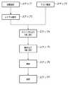
次に、図9及び図10を参照して、上述の各実施形態に係る露光装置1を利用したデバイスの製造方法の実施例を説明する。図9は、デバイス(ICやLSIなどの半導体チップ、LCD、CCD等)の製造を説明するためのフローチャートである。ここでは、半導体チップの製造を例に説明する。ステップ1(回路設計)では、デバイスの回路設計を行う。ステップ2(マスク製作)では、設計した回路パターンを形成したマスクを製作する。ステップ3(ウエハ製造)では、シリコンなどの材料を用いてウエハを製造する。ステップ4(ウエハプロセス)は、前工程と呼ばれ、マスクとウエハを用いて本発明のリソグラフィー技術によってウエハ上に実際の回路を形成する。ステップ5(組み立て)は、後工程と呼ばれ、ステップ4によって作成されたウエハを用いて半導体チップ化する工程であり、アッセンブリ工程(ダイシング、ボンディング)、パッケージング工程(チップ封入)等の工程を含む。ステップ6(検査)では、ステップ5で作成された半導体デバイスの動作確認テスト、耐久性テストなどの検査を行う。こうした工程を経て半導体デバイスが完成し、これが出荷(ステップ7)される。(Fourth embodiment)
Next, an example of a device manufacturing method using the exposure apparatus 1 according to each of the above-described embodiments will be described with reference to FIGS. FIG. 9 is a flowchart for explaining how to fabricate devices (ie, semiconductor chips such as IC and LSI, LCDs, CCDs, and the like). Here, the manufacture of a semiconductor chip will be described as an example. In step 1 (circuit design), a device circuit is designed. In step 2 (mask production), a mask on which the designed circuit pattern is formed is produced. In step 3 (wafer manufacture), a wafer is manufactured using a material such as silicon. Step 4 (wafer process) is called a pre-process, and an actual circuit is formed on the wafer by the lithography technique of the present invention using the mask and the wafer. Step 5 (assembly) is called a post-process, and is a process for forming a semiconductor chip using the wafer created in
図10は、ステップ4のウエハプロセスの詳細なフローチャートである。ステップ11(酸化)では、ウエハの表面を酸化させる。ステップ12(CVD)では、ウエハの表面に絶縁膜を形成する。ステップ13(電極形成)では、ウエハ上に電極を蒸着などによって形成する。ステップ14(イオン打ち込み)では、ウエハにイオンを打ち込む。ステップ15(レジスト処理)では、ウエハに感光剤を塗布する。ステップ16(露光)では、露光装置1によってマスクパターンをウエハに露光する。ステップ17(現像)では、露光したウエハを現像する。ステップ18(エッチング)では、現像したレジスト像以外の部分を削り取る。ステップ19(レジスト剥離)では、エッチングが済んで不要となったレジストを取り除く。これらのステップを繰り返し行うことによってウエハ上に多重に回路パターンが形成される。かかるデバイス製造方法によれば、従来よりも高品位のデバイスを製造することができる。このように、露光装置1を使用するデバイス製造方法、並びに結果物としてのデバイスも本発明の一側面を構成する。 FIG. 10 is a detailed flowchart of the wafer process in
Claims (9)
Translated fromJapanese基板ステージ上に保持されている前記基板と、前記基板の外周部の周辺領域とを略同一面にして前記基板の外周部に液体を保持する同面部材を備え、
前記同面部材は、
前記基板の外周部の周辺領域に構成され、前記基板の外周部に液体を保持する内側部材と、
前記内側部材の外周部に構成され、前記基板ステージに取り付けられる外側部材と、
前記内側部材と前記外側部材とを結合する結合部材と、
を有することを特徴とする露光装置。An exposure apparatus that exposes a pattern of an original on the substrate in a state where a space between the projection optical system and the substrate is filled with a liquid,
A coplanar member that holds the liquid on the outer peripheral portion of the substrate with the substrate held on the substrate stage and the peripheral region of the outer peripheral portion of the substrate being substantially flush with each other;
The coplanar member is
An inner member configured in a peripheral region of the outer peripheral portion of the substrate, and holding liquid on the outer peripheral portion of the substrate;
An outer member configured on the outer periphery of the inner member and attached to the substrate stage;
A coupling member that couples the inner member and the outer member;
An exposure apparatus comprising:
基板ステージ上に保持されている前記基板と、前記基板の外周部の周辺領域とを略同一面にして前記基板の外周部に液体を保持する同面部材と、
前記同面部材を前記基板ステージ上に取り付けるための取付部材と、
を備え、
前記取付部材は、前記同面部材に生じた変形を弾性変形により吸収し、前記基板ステージに伝達される変形を低減させることを特徴とする露光装置。An exposure apparatus that exposes a pattern of an original on the substrate in a state where a space between the projection optical system and the substrate is filled with a liquid,
The same surface member that holds the liquid on the outer peripheral portion of the substrate, with the substrate held on the substrate stage and the peripheral region of the outer peripheral portion of the substrate being substantially flush with each other,
An attachment member for attaching the same surface member on the substrate stage;
With
The exposure apparatus according to claim 1, wherein the attachment member absorbs deformation generated in the coplanar member by elastic deformation and reduces deformation transmitted to the substrate stage.
前記離間部は、前記外側部材に対して、前記液体により冷却される前記内側部材に生じる温度変化を断熱することを特徴とする請求項1に記載の露光装置。Further comprising a separation portion having a gap between the inner member and the outer member,
The exposure apparatus according to claim 1, wherein the separation unit insulates a temperature change generated in the inner member cooled by the liquid from the outer member.
前記取付部材は、前記同面部材に生じた変形を弾性変形により吸収し、前記基板ステージに伝達される変形を低減させることを特徴とする請求項1に記載の露光装置。An attachment member for attaching the coplanar member onto the substrate stage;
The exposure apparatus according to claim 1, wherein the attachment member absorbs deformation generated in the coplanar member by elastic deformation and reduces deformation transmitted to the substrate stage.
前記露光された基板を現像する工程と、
を有することを特徴とするデバイス製造方法。A step of exposing the substrate using the exposure apparatus according to claim 1;
Developing the exposed substrate;
A device manufacturing method comprising:
Priority Applications (4)
| Application Number | Priority Date | Filing Date | Title |
|---|---|---|---|
| JP2006092338AJP2007266504A (en) | 2006-03-29 | 2006-03-29 | Exposure equipment |
| US11/685,449US7705969B2 (en) | 2006-03-29 | 2007-03-13 | Exposure apparatus |
| TW096108637ATW200739278A (en) | 2006-03-29 | 2007-03-13 | Exposure apparatus |
| KR1020070026552AKR100883810B1 (en) | 2006-03-29 | 2007-03-19 | Exposure device |
Applications Claiming Priority (1)
| Application Number | Priority Date | Filing Date | Title |
|---|---|---|---|
| JP2006092338AJP2007266504A (en) | 2006-03-29 | 2006-03-29 | Exposure equipment |
Publications (2)
| Publication Number | Publication Date |
|---|---|
| JP2007266504Atrue JP2007266504A (en) | 2007-10-11 |
| JP2007266504A5 JP2007266504A5 (en) | 2009-05-14 |
Family
ID=38558376
Family Applications (1)
| Application Number | Title | Priority Date | Filing Date |
|---|---|---|---|
| JP2006092338AWithdrawnJP2007266504A (en) | 2006-03-29 | 2006-03-29 | Exposure equipment |
Country Status (4)
| Country | Link |
|---|---|
| US (1) | US7705969B2 (en) |
| JP (1) | JP2007266504A (en) |
| KR (1) | KR100883810B1 (en) |
| TW (1) | TW200739278A (en) |
Cited By (3)
| Publication number | Priority date | Publication date | Assignee | Title |
|---|---|---|---|---|
| JP2008172214A (en)* | 2006-12-08 | 2008-07-24 | Asml Netherlands Bv | Substrate support and lithography process |
| JP2016189027A (en)* | 2012-05-29 | 2016-11-04 | エーエスエムエル ネザーランズ ビー.ブイ. | Support apparatus, lithographic apparatus, and device manufacturing method |
| JP2017032999A (en)* | 2012-05-29 | 2017-02-09 | エーエスエムエル ネザーランズ ビー.ブイ. | Object holder and lithographic apparatus |
Families Citing this family (13)
| Publication number | Priority date | Publication date | Assignee | Title |
|---|---|---|---|---|
| SG10201801998TA (en)* | 2004-09-17 | 2018-04-27 | Nikon Corp | Substrate holding device, exposure apparatus, and device manufacturing method |
| US7433016B2 (en) | 2005-05-03 | 2008-10-07 | Asml Netherlands B.V. | Lithographic apparatus and device manufacturing method |
| JP5020662B2 (en) | 2006-05-26 | 2012-09-05 | キヤノン株式会社 | Stage apparatus, exposure apparatus, and device manufacturing method |
| US20080198346A1 (en)* | 2007-02-16 | 2008-08-21 | Canon Kabushiki Kaisha | Exposure apparatus and method for manufacturing device |
| US20080198348A1 (en)* | 2007-02-20 | 2008-08-21 | Nikon Corporation | Apparatus and methods for minimizing force variation from immersion liquid in lithography systems |
| US8514365B2 (en)* | 2007-06-01 | 2013-08-20 | Asml Netherlands B.V. | Lithographic apparatus and device manufacturing method |
| JP2010140958A (en)* | 2008-12-09 | 2010-06-24 | Canon Inc | Exposure apparatus, and device manufacturing method |
| NL2005874A (en)* | 2010-01-22 | 2011-07-25 | Asml Netherlands Bv | A lithographic apparatus and a device manufacturing method. |
| JP5918965B2 (en) | 2011-10-25 | 2016-05-18 | キヤノン株式会社 | Processing machine system and processing machine arrangement method |
| JP5943742B2 (en)* | 2012-07-04 | 2016-07-05 | 三菱電機株式会社 | Semiconductor test jig and semiconductor test method using the same |
| US10578959B2 (en) | 2015-04-29 | 2020-03-03 | Asml Netherlands B.V. | Support apparatus, lithographic apparatus and device manufacturing method |
| NL2017014A (en) | 2015-06-23 | 2016-12-29 | Asml Netherlands Bv | A Support Apparatus, a Lithographic Apparatus and a Device Manufacturing Method |
| WO2024188552A1 (en)* | 2023-03-13 | 2024-09-19 | Asml Netherlands B.V. | Substrate support and lithographic apparatus |
Family Cites Families (22)
| Publication number | Priority date | Publication date | Assignee | Title |
|---|---|---|---|---|
| JP2002158154A (en)* | 2000-11-16 | 2002-05-31 | Canon Inc | Exposure equipment |
| CN100568101C (en) | 2002-11-12 | 2009-12-09 | Asml荷兰有限公司 | Photolithography apparatus and device manufacturing method |
| CN101470360B (en)* | 2002-11-12 | 2013-07-24 | Asml荷兰有限公司 | Immersion lithographic apparatus and device manufacturing method |
| KR100585476B1 (en)* | 2002-11-12 | 2006-06-07 | 에이에스엠엘 네델란즈 비.브이. | Lithographic Apparatus and Device Manufacturing Method |
| US7372541B2 (en)* | 2002-11-12 | 2008-05-13 | Asml Netherlands B.V. | Lithographic apparatus and device manufacturing method |
| SG121822A1 (en)* | 2002-11-12 | 2006-05-26 | Asml Netherlands Bv | Lithographic apparatus and device manufacturing method |
| US7110081B2 (en)* | 2002-11-12 | 2006-09-19 | Asml Netherlands B.V. | Lithographic apparatus and device manufacturing method |
| DE60335595D1 (en)* | 2002-11-12 | 2011-02-17 | Asml Netherlands Bv | Immersion lithographic apparatus and method of making a device |
| JP4529433B2 (en) | 2002-12-10 | 2010-08-25 | 株式会社ニコン | Exposure apparatus, exposure method, and device manufacturing method |
| KR20120127755A (en)* | 2002-12-10 | 2012-11-23 | 가부시키가이샤 니콘 | Exposure apparatus and method for manufacturing device |
| TWI295414B (en)* | 2003-05-13 | 2008-04-01 | Asml Netherlands Bv | Lithographic apparatus and device manufacturing method |
| US7213963B2 (en)* | 2003-06-09 | 2007-05-08 | Asml Netherlands B.V. | Lithographic apparatus and device manufacturing method |
| JP2005072132A (en) | 2003-08-21 | 2005-03-17 | Nikon Corp | Exposure apparatus and device manufacturing method |
| TWI263859B (en)* | 2003-08-29 | 2006-10-11 | Asml Netherlands Bv | Lithographic apparatus and device manufacturing method |
| US8854602B2 (en)* | 2003-11-24 | 2014-10-07 | Asml Netherlands B.V. | Holding device for an optical element in an objective |
| KR101394764B1 (en)* | 2003-12-03 | 2014-05-27 | 가부시키가이샤 니콘 | Exposure apparatus, exposure method, device producing method, and optical component |
| JP2005175016A (en)* | 2003-12-08 | 2005-06-30 | Canon Inc | Substrate holding apparatus, exposure apparatus using the same, and device manufacturing method |
| US7227619B2 (en)* | 2004-04-01 | 2007-06-05 | Asml Netherlands B.V. | Lithographic apparatus and device manufacturing method |
| JP2005302880A (en) | 2004-04-08 | 2005-10-27 | Canon Inc | Immersion exposure equipment |
| JP2007123525A (en)* | 2005-10-27 | 2007-05-17 | Toshiba Corp | Immersion exposure apparatus and semiconductor device manufacturing method |
| US7787101B2 (en)* | 2006-02-16 | 2010-08-31 | International Business Machines Corporation | Apparatus and method for reducing contamination in immersion lithography |
| US20080198346A1 (en)* | 2007-02-16 | 2008-08-21 | Canon Kabushiki Kaisha | Exposure apparatus and method for manufacturing device |
- 2006
- 2006-03-29JPJP2006092338Apatent/JP2007266504A/ennot_activeWithdrawn
- 2007
- 2007-03-13TWTW096108637Apatent/TW200739278A/enunknown
- 2007-03-13USUS11/685,449patent/US7705969B2/ennot_activeExpired - Fee Related
- 2007-03-19KRKR1020070026552Apatent/KR100883810B1/ennot_activeExpired - Fee Related
Cited By (9)
| Publication number | Priority date | Publication date | Assignee | Title |
|---|---|---|---|---|
| JP2008172214A (en)* | 2006-12-08 | 2008-07-24 | Asml Netherlands Bv | Substrate support and lithography process |
| JP2016189027A (en)* | 2012-05-29 | 2016-11-04 | エーエスエムエル ネザーランズ ビー.ブイ. | Support apparatus, lithographic apparatus, and device manufacturing method |
| JP2017032999A (en)* | 2012-05-29 | 2017-02-09 | エーエスエムエル ネザーランズ ビー.ブイ. | Object holder and lithographic apparatus |
| US9785055B2 (en) | 2012-05-29 | 2017-10-10 | Asml Netherlands B.V. | Object holder and lithographic apparatus |
| US9915877B2 (en) | 2012-05-29 | 2018-03-13 | Asml Netherlands B.V. | Object holder and lithographic apparatus |
| JP2018136560A (en)* | 2012-05-29 | 2018-08-30 | エーエスエムエル ネザーランズ ビー.ブイ. | Object holder and lithographic apparatus |
| US10120292B2 (en) | 2012-05-29 | 2018-11-06 | Asml Netherlands, B.V. | Support apparatus, lithographic apparatus and device manufacturing method |
| US10481502B2 (en) | 2012-05-29 | 2019-11-19 | Asml Netherlands B.V. | Object holder and lithographic apparatus |
| US10747125B2 (en) | 2012-05-29 | 2020-08-18 | Asml Netherlands B.V. | Support apparatus, lithographic apparatus and device manufacturing method |
Also Published As
| Publication number | Publication date |
|---|---|
| KR20070098527A (en) | 2007-10-05 |
| US7705969B2 (en) | 2010-04-27 |
| KR100883810B1 (en) | 2009-02-16 |
| US20070229787A1 (en) | 2007-10-04 |
| TW200739278A (en) | 2007-10-16 |
Similar Documents
| Publication | Publication Date | Title |
|---|---|---|
| JP2007266504A (en) | Exposure equipment | |
| JP6512252B2 (en) | Exposure apparatus, exposure method, and device manufacturing method | |
| US8169590B2 (en) | Exposure apparatus and device fabrication method | |
| US7932996B2 (en) | Exposure apparatus, exposure method, and device fabrication method | |
| US20080043211A1 (en) | Apparatus and methods for recovering fluid in immersion lithography | |
| US20060285093A1 (en) | Immersion exposure apparatus | |
| JP4961299B2 (en) | Exposure apparatus and device manufacturing method | |
| WO2009099021A1 (en) | Stage apparatus, exposure apparatus, exposure method, and device fabrication method | |
| JP5429229B2 (en) | Immersion exposure apparatus, immersion exposure method, and device manufacturing method | |
| JP2007184336A (en) | Exposure apparatus and device manufacturing method | |
| US20090091715A1 (en) | Exposure apparatus, exposure method, and device manufacturing method | |
| JP2008235620A (en) | Immersion exposure equipment | |
| JP2008140957A (en) | Immersion exposure equipment | |
| JP2007115730A (en) | Exposure equipment | |
| JP2006319065A (en) | Exposure equipment | |
| JP2007019392A (en) | Exposure equipment | |
| JP2008140959A (en) | Immersion exposure equipment | |
| JP2008262963A (en) | Immersion exposure apparatus and device manufacturing method | |
| JP2007027435A (en) | Exposure equipment | |
| JP2007012832A (en) | Exposure equipment |
Legal Events
| Date | Code | Title | Description |
|---|---|---|---|
| A521 | Written amendment | Free format text:JAPANESE INTERMEDIATE CODE: A523 Effective date:20090330 | |
| A621 | Written request for application examination | Free format text:JAPANESE INTERMEDIATE CODE: A621 Effective date:20090330 | |
| A761 | Written withdrawal of application | Free format text:JAPANESE INTERMEDIATE CODE: A761 Effective date:20110216 |